TCO Certified - Generation 9, for all-in-one PCs
176
TCO Certified Generation 9, for all-in-one PCs
-
Upload
khangminh22 -
Category
Documents
-
view
1 -
download
0
Transcript of TCO Certified - Generation 9, for all-in-one PCs

TCO CertifiedGeneration 9, for all-in-one PCs
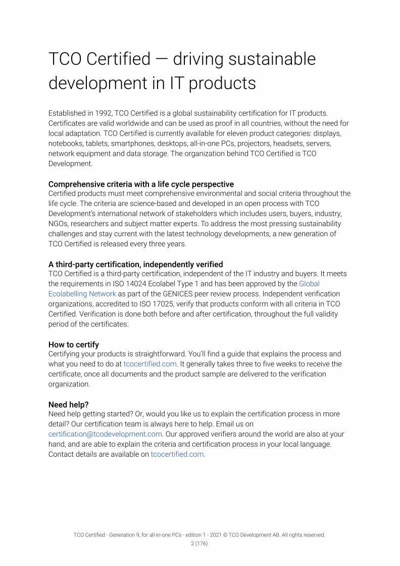
TCO Certified — driving sustainabledevelopment in IT productsEstablished in 1992, TCO Certified is a global sustainability certification for IT products.Certificates are valid worldwide and can be used as proof in all countries, without the need forlocal adaptation. TCO Certified is currently available for eleven product categories: displays,notebooks, tablets, smartphones, desktops, all-in-one PCs, projectors, headsets, servers,network equipment and data storage. The organization behind TCO Certified is TCODevelopment.
Comprehensive criteria with a life cycle perspectiveCertified products must meet comprehensive environmental and social criteria throughout thelife cycle. The criteria are science-based and developed in an open process with TCODevelopment’s international network of stakeholders which includes users, buyers, industry,NGOs, researchers and subject matter experts. To address the most pressing sustainabilitychallenges and stay current with the latest technology developments, a new generation ofTCO Certified is released every three years.
A third-party certification, independently verifiedTCO Certified is a third-party certification, independent of the IT industry and buyers. It meetsthe requirements in ISO 14024 Ecolabel Type 1 and has been approved by the GlobalEcolabelling Network as part of the GENICES peer review process. Independent verificationorganizations, accredited to ISO 17025, verify that products conform with all criteria in TCOCertified. Verification is done both before and after certification, throughout the full validityperiod of the certificates.
How to certifyCertifying your products is straightforward. You’ll find a guide that explains the process andwhat you need to do at tcocertified.com. It generally takes three to five weeks to receive thecertificate, once all documents and the product sample are delivered to the verificationorganization.
Need help?Need help getting started? Or, would you like us to explain the certification process in moredetail? Our certification team is always here to help. Email us [email protected]. Our approved verifiers around the world are also at yourhand, and are able to explain the criteria and certification process in your local language.Contact details are available on tcocertified.com.
TCO Certified - Generation 9, for all-in-one PCs - edition 1 - 2021 © TCO Development AB. All rights reserved.2 (176)

About this documentThis is TCO Certified, generation 9, for all-in-one PCs, released in December 2021. An all-in-onePC is defined as a stationary computer and display in a single unit. The definition includesstationary thin clients. All power cables and external power supplies are considered a part ofthe all-in-one PC. All other peripherals (i.e. keyboard and mouse) that may be shipped with theall-in-one PC are not covered by TCO Certified.
All product categories are generation 9TCO Certified is available for twelve product categories and they all have the same generationnumber: generation 9. A majority of the criteria are the same for all product categories.
The criteria include:Mandate: A description of the requirements that needs to be fulfilled, and how conformity isverified. Forms and signatures for application are available in chapter 11 of this document.Definitions: Explanations of important terms relevant to the criterion.References: References to sources, presented in chapter 10.Clarifications: Further details and explanations of the mandate.
ConformityConformity with the mandates is verified by verification organizations (verifiers) independentof both the certification body (TCO Development), the applicant and the brand owner. Eachmandate includes a description of the proof that must be submitted to the verifier, and to TCODevelopment together with the application form. This may be a test report or a verificationreport:
1. A test report presents the results from tests conducted by a test facility accredited toISO 17025, and is issued by that same facility.
2. A verification report is issued by a verifier approved by TCO Development and includesa summary and a result (pass or fail) based on either:
● a test report issued by the same test facility,● a test report issued by a different test facility, or● certificates or other proof from the company or brand owner applying for the
certificate.
Editions of TCO CertifiedWhen we publish a new generation of TCO Certified, our ambition is always to maintaincriteria levels until the next generation of TCO Certified is launched, which typically happensafter three years. Several editions of the criteria document may be released, but will beconsidered only as updates within the ninth generation, with improved precision of themandates, test methods and clarifications. To ensure that all currently certified productscomplies with the new edition of the criteria document, the criteria levels are never raisedwithin a generation.
TCO Certified - Generation 9, for all-in-one PCs - edition 1 - 2021 © TCO Development AB. All rights reserved.3 (176)

Table of contents1 Product and sustainability information 9
1.1 Information to end users 101.1.1 Mandate 101.1.2 Clarification 10
1.2 Product specification 131.2.1 Mandate 131.2.2 Clarification 14
1.3 Sustainability performance indicators 151.3.1 Mandate 151.3.2 Clarification 151.3.3 Sustainability Performance Indicators (SPI) list 16
2 Socially responsible manufacturing 192.1 Supply chain responsibility 20
2.1.1 Mandate 202.1.2 Clarification 22
2.2 Supply chain transparency 342.2.1 Mandate 342.2.2 Clarifications 35
2.3 Anti-bribery management system 372.3.1 Mandate 372.3.2 Clarification 38
2.4 Responsibly sourced minerals 392.4.1 Mandate 392.4.2 Clarifications 40
2.5 Process chemicals management 432.5.1 Mandate 432.5.2 Clarification 44
3 Environmentally responsible manufacturing 463.1 Environmental management system 47
3.1.1 Mandate 473.1.2 Clarification 48
3.2 Energy efficiency indicators 493.2.1 Mandate 49
3.3 Energy management system 503.3.1 Mandate 503.3.2 Clarification 50
3.4 Post-consumer recycled content 513.4.1 Mandate 513.4.2 Clarification 52TCO Certified - Generation 9, for all-in-one PCs - edition 1 - 2021 © TCO Development AB. All rights reserved.
4 (176)

3.5 Product carbon footprint 543.5.1 Mandate 543.5.2 Clarification 55
4 User health and safety 574.1 Electrical safety 58
4.1.1 Mandate 584.2 Alternating electric fields 59
4.2.1 Mandate 594.2.2 Clarification 59
4.3 Alternating magnetic fields 644.3.1 Mandate 644.3.2 Clarification 65
4.4 Acoustic noise 684.4.1 Mandate 694.4.2 Clarification 69
4.5 Vertical tilt 724.5.1 Mandate 724.5.2 Clarification 72
4.6 Vertical height 734.6.1 Mandate 734.6.2 Clarification 74
5 Product performance 755.1 Energy efficiency 76
5.1.1 Mandate 765.1.2 Clarification 77
5.2 Display resolution 825.2.1 Mandate 825.2.2 Clarification 83
5.3 Correlated color temperature 845.3.1 Mandate 845.3.2 Clarification 85
5.4 Color gamut 865.4.1 Mandate 865.4.2 Clarification 86
5.5 Color uniformity 885.5.1 Mandate 885.5.2 Clarification 88
5.6 Color uniformity – angular dependence 915.6.1 Mandate 915.6.2 Clarification 91
5.7 Color grayscale linearity 945.7.1 Mandate 94
TCO Certified - Generation 9, for all-in-one PCs - edition 1 - 2021 © TCO Development AB. All rights reserved.5 (176)

5.7.2 Clarification 955.8 Luminance level 96
5.8.1 Mandate 965.8.2 Clarification 96
5.9 Luminance uniformity 995.9.1 Mandate 995.9.2 Clarification 99
5.10 Luminance uniformity — angular-dependence 1015.10.1 Mandate 1015.10.2 Clarification 101
5.11 Luminance contrast – characters 1055.11.1 Mandate 1055.11.2 Clarification 105
5.12 Luminance contrast – angular dependence 1085.12.1 Mandate 1085.12.2 Clarification 109
5.13 Black level 1105.13.1 Mandate 1105.13.2 Clarification 110
5.14 Grayscale gamma curve 1125.14.1 Mandate 1125.14.2 Clarification 112
6 Product lifetime extension 1146.1 Product warranty 115
6.1.1 Mandate 1156.2 Replaceable components 118
6.2.1 Mandate 1196.2.2 Clarification 119
6.3 Standardized connectors 1276.3.1 Mandate 1276.3.2 Clarification 127
6.4 Secure data removal 1286.4.1 Mandate 1286.4.2 Clarification 129
7 Reduction of hazardous substances 1307.1 Heavy metals 131
7.1.1 Mandate 1317.2 Halogens 132
7.2.1 Mandate 1327.2.2 Clarification 133
7.3 Non-halogenated substances 1347.3.1 Mandate 135
TCO Certified - Generation 9, for all-in-one PCs - edition 1 - 2021 © TCO Development AB. All rights reserved.6 (176)

7.3.2 Clarification 1357.4 Plasticizers 138
7.4.1 Mandate 1397.4.2 Clarification 139
7.5 Hazardous substances in product packaging 1407.5.1 Mandate 1407.5.2 Clarification 140
8 Material recovery 1418.1 Product packaging 142
8.1.1 Mandate 1428.1.2 Clarification 142
8.2 E-waste management 1438.2.1 Mandate 1438.2.2 Clarification 144
8.3 Material coding of plastics 1468.3.1 Mandate 1468.3.2 Clarification 147
9 Test conditions for all-in-one PCs 1489.1 General test conditions 148
9.1.1 Definition of a test object 1489.1.2 Required information about the product 1489.1.3 Test conditions 1489.1.4 Product alignment for testing 1489.1.5 Settings of the all-in-one PC 1499.1.6 Test image/test character 1499.1.7 Test image and test luminance setting 1509.1.8 Instruments used for testing 1519.1.9 Test report 1519.1.10 Overall uncertainty 151
9.2 Visual ergonomics 1529.2.1 General test requirements 1529.2.2 Photometric test facility general requirements 1529.2.3 Power supply and test room climate requirements for testing 1529.2.4 Photometric and spectrometric measurements 1529.2.5 Measurement distance 1539.2.6 Stray light 153
9.3 Emissions 1549.3.1 General test requirements 1549.3.2 Power supply and test room climate requirements for testing 1549.3.3 Product conditions and setup 1549.3.4 Emission measurement instruments 1579.3.5 Acoustic noise 160
TCO Certified - Generation 9, for all-in-one PCs - edition 1 - 2021 © TCO Development AB. All rights reserved.7 (176)

9.3.6 Overall uncertainty 160
10 References 161
11 Forms and signatures for application 16611.1 Brand owner form 167
11.1.1 Supply chain responsibility (mandate 2.1.1) 16711.1.2 Supply chain transparency (mandate 2.2.1) 16711.1.3 Anti-bribery management system (mandate 2.3.1) 16711.1.4 Responsibly sourced minerals (mandate 2.4.1) 167
11.2 Factory form 16911.2.1 Supply chain responsibility (mandate 2.1.1) 16911.2.2 Process chemicals management (mandate 2.5.1) 16911.2.3 Environmental management system (mandate 3.1.1) 16911.2.4 Energy efficiency indicators (mandate 3.2.1) 16911.2.5 Energy management system (mandate 3.3.1) 169
11.3 Product form 17011.3.1 Information to end users (mandate 1.1.1) 17011.3.2 Product specification (mandate 1.2.1) 17011.3.3 Sustainability performance (mandate 1.3.1) 17111.3.4 Non-mandatory sustainability performance indicators (mandate 1.3.1) 17111.3.5 Post-consumer recycled content (mandate 3.4) 17111.3.6 Electrical safety (mandate 4.1.1) 17211.3.7 Acoustic noise (mandate 4.4.1) 17211.3.8 Vertical tilt (mandate 4.5.1) 17211.3.9 Vertical height (mandate 4.6.1) 17211.3.10 Energy efficiency (mandate 5.1.1) 17211.3.11 Standardized connectors (mandate 6.3.1) 17211.3.12 Secure data removal (mandate 6.4.1) 17211.3.13 Hazardous substances 17311.3.14 Material recovery 173
11.4 Brand owner product form 17411.4.1 Product warranty (mandate 6.1.1) 17411.4.2 Replaceable components (mandate 6.2.1) 17411.4.3 E-waste management (mandate 8.2.1) 17411.4.4 Factory identification (mandate 2.1.1) 174
11.5 Certification documents 175
TCO Certified - Generation 9, for all-in-one PCs - edition 1 - 2021 © TCO Development AB. All rights reserved.8 (176)

1 Product and sustainabilityinformationTCO Certified — sustainability certification in accordance with ISO 14024TCO Certified is a third-party certification that meets the requirements of ISO 14024 EcolabelType 1. The certification has been assessed and approved by the Global Ecolabelling Network,as part of the GENICES peer review process. The ISO 14024 standard establishes theprinciples and procedures for third-party ecolabels, ensuring that consumers and professionalpurchasers are given accurate and comparable information. Criteria must cover the productlife cycle and be based on scientific principles. Compliance with criteria must be verified by anindependent party.
Data gathering in TCO CertifiedTo measure the impact of TCO Certified and the sustainability benefits of certified products,TCO Development continually collects data based on the use of the certification. The collecteddata is used in several ways:
● For TCO Development, the data is crucial for the continuous development of TCOCertified. It is used to ensure that criteria are set at reasonable levels and that themost relevant sustainability challenges are being addressed, throughout the product’slife cycle.
● Manufacturers and brand owners use the data to verify their performance in varioussustainability areas, and compare with their peers.
● Other stakeholders, such as purchasing organizations, use the data as keyperformance indicators to determine the sustainability benefits for their organizationby asking for TCO Certified, and to track this over time.
TCO Certified - Generation 9, for all-in-one PCs - edition 1 - 2021 © TCO Development AB. All rights reserved.9 (176)

1.1 Information to end usersBackgroundEnd users must clearly be able to identify which products are certified and what sustainabilityfeatures the product fulfills.
ApplicabilityAll product categories.
ReferencesThe license agreement between TCO Development and the applicant/brand owner.
1.1.1 Mandatea. The information document for end users must be written in English or in the local
language of the country where the product is to be sold. It must accompany theproduct in at least one of the following ways:
1. As a separate printed or digital document.2. Included in a printed or digital user manual.3. As a separate digital document that is hosted on the brand owner's
website. A direct link to the document must be included in the printed ordigital user manual mentioned above.
b. The product and its retail packaging must be labeled with the TCO Certified logo.See clarifications for details.
c. “TCO Certified” must be mentioned on the brand owner's website(s) where thespecific certified product is marketed and or sold.
Submit the following to an approved verifier:● A completed and signed product form (chapter 11.3).
Submit the following together with the application to TCO Development:A copy of the verification report(s) from a verifier approved by TCO Development.
1.1.2 ClarificationProducts that are designed to be installed in a rack (supporting framework to hold hardwaremodules, typically servers, data storage products and networking equipment) are excludedfrom “Part 2 - labeling of the product and packaging”.
Part 1: information document for end usersNo editorial changes to the information document for end users are accepted without consentfrom TCO Development. The information document for end users is available attcocertified.com.If the applicant is separate from the brand owner, the applicant must ensure that the brandowner agrees to fulfill their part of this requirement.
TCO Certified - Generation 9, for all-in-one PCs - edition 1 - 2021 © TCO Development AB. All rights reserved.10 (176)

The mandate is fulfilled in one of the following ways:1. As a separate printed or digital document
The information document for end users in print or on digital media is placed togetherwith the product in the packaging.
2. In a printed or digital user manualThe information document for end users is included in a printed or digital user manualthat accompanies the product when it is distributed to the end user. The content of thedocument, with the headline “TCO Certified”, must be a separate chapter of the usermanual and be included in the table of contents.
3. As a separate digital document that is hosted on the brand owner's website.The information document for end users is placed on the brand owner’s website. Adirect link to the information document is placed in the printed or digital user manualthat accompanies the product when it is distributed to the end user. TCO Certifiedmust be a separate headline in the user manual. The headline must be visible in thetable of contents.
Part 2 - labeling of the product and packaging
The TCO Certified logo must be displayed in one of the following ways:
Alternative AOn a permanent or temporary label. Temporary labels must be affixed to the product with anadhesive or cling-type application. The packaging material that is supposed to be removed inorder to get the full functionality of a product (such as a screen protector) is defined aspackaging material and not the product in this mandate and thus may not be the place for theproduct logo.
a. The logo must be visible on the top or front of the product. (The front of theproduct is defined as the surface seen when viewing the product from the frontand may include the stand. The top is defined as the surface that is seen fromthe top and the back is the surface that is seen from the back.)
b. The minimum size of the logo is 16mm in width and 10mm in height.c. If the logo is to be placed alongside other logos or graphic elements, a
minimum of 2,5mm padding must be used on all sides of the TCO Certifiedlogo.
ExceptionIf the top and front of the product don’t have a contiguous and coplanar area(area used for display or touch input are excluded) which is at least 16mm inwidth or 10mm in height, then the logo may be placed on the back side of theproduct.
or
TCO Certified - Generation 9, for all-in-one PCs - edition 1 - 2021 © TCO Development AB. All rights reserved.11 (176)

Alternative BVia electronic labeling displayed on the screen in one of the below ways:
a. During the startup of the product:The logo must cover at least 1% of the screen. The logo must be legible and bein color, black, or white; must appear at system start-up, and must be displayedfor a minimum of 0,5 seconds.
b. Via a shortcut on the desktop screen of the product. The shortcut must be inthe form of the TCO Certified logo in color and clicking it should link to “theinformation document for end users” available at tcocertified.com.
c. TCO Certified logo as a part of the product picture The TCO Certified logo isshown on the first product picture where the product is marketed on the brandowners web site. In the product specification on this page, TCO Certified is alsolisted with a link to the “information to end-user document” which is thedocument required under mandate 1.1 point 1.
TCO Development will consider alternative proposals for electronic labeling on a case-by-casebasis.
The retail packaging of the product must be labeled with the TCO Certified logo:a. The minimum size of the logo must be 16mm in width and 10mm in height.b. If the logo is to be placed alongside other logos or graphic elements, a
minimum of 2,5mm padding must be used on all sides of the TCO Certifiedlogo.
The certificate owner and brand owner must also conform with all the other logo rules oncolor, design, marketing, etc., that are specified in the TCO Certified license agreementappendix 2. The following two paragraphs (§2.2 and §2.5 in appendix 2 of the licenseagreement) are replaced by the rules listed above if a conflict occurs:
Paragraphs that may be replaced:§2.5 The TCO Certified logo must at all times be reproduced in a quality that allows the text
of the TCO Certified logo to be read under normal circumstances. Recommendedminimum size for the trademarks TCO Certified and TCO Certified Edge can be found in“Using the TCO Certified brand” guide available at tcocertified.com. If there arelimitations and a smaller or different type of logo is used this must first be agreed on inwriting with TCO Development.
Part 3 - Mention of TCO Certified on the brand owner website● The inclusion of “TCO Certified” only needs to be represented as TEXT - i.e. a link to a
specific page is not necessary.● Instead of mentioning “TCO Certified” directly on the brand owners website(s), the
brand owner can fulfill this requirement by including “TCO Certified” as TEXT in aproduct specific PDF file if it is accessible from the brand owner's website(s) where thespecific certified product is marketed and or sold.
TCO Certified - Generation 9, for all-in-one PCs - edition 1 - 2021 © TCO Development AB. All rights reserved.12 (176)

1.2 Product specificationBackgroundIt is important to ensure that each product to be certified corresponds exactly to the productspecification. Therefore, a physical sample of each product to be certified must be sent to anapproved verifier, that examines it carefully to ensure that product marking and physicalaspects conform with the reported information from the applicant or brand owner.
DefinitionThe marking label is a label with the product’s electrical rating (voltage, frequency, current), themanufacturer’s name, trademark or identification mark, and the manufacturer’s model or typereference according to IEC 60 950:1 clause 1.7.1.
ApplicabilityAll product categories.
References1.1.
1.2.1 Mandate● A product specification of the typical product.● A marking label must be provided for the product.● The total weight of the typical product configuration and power supply (without
packaging) in kg must be reported.
Submit the following to an approved verifier:1. A copy of the marking label, for the product and all external power supplies.2. A completed and signed product form (chapter 11.3).
Submit the following together with the application to TCO Development:1. A copy of the verification report(s) from a verifier approved by TCO Development.2. The total weight of the typical product configuration and power supply (without
packaging) in kg must be reported in TCO Certified Portal.
TCO Certified - Generation 9, for all-in-one PCs - edition 1 - 2021 © TCO Development AB. All rights reserved.13 (176)

1.2.2 ClarificationThe template must be completed with the requested information about the product. A typekey that includes an asterisk (*) for unidentified characters, if any, in the model name and forother identification names must be submitted to the verifier. Only two * may be used in themodel type key and each * must include two or more options.
The typical product configuration is defined as the product configuration which is expected tobe manufactured in the largest number.
The total weight includes the product and any power supply unit and power cable needed topower the device.
Sustainability performance indicator(s):Product weight is an indication of the amount of potential e-waste at end-of-life. Bydecreasing the product weight, e-waste can be reduced. The product weight (in kg) of thetypical configuration of the product including any power supply but excluding packaging mustbe reported by the brand owner. A product weight tolerance of +/- 10% is accepted.
TCO Certified - Generation 9, for all-in-one PCs - edition 1 - 2021 © TCO Development AB. All rights reserved.14 (176)

1.3 Sustainability performance indicatorsBackgroundSustainability is a long term goal and therefore a responsible way to work with sustainability isthrough a long term strategy. Improvements must often be phased in gradually and requiresplanning and preparation. The sustainability performance indicators will measure thedevelopment of products and brand owners, enabling new criteria levels in future generationsof TCO Certified to be challenging but yet reasonable, and ensure that the most relevant partsof the product life cycle is covered.
The sustainability performance indicators also measure the sustainability benefits that thecertified products create, and track this over time. A purchasing organization can use thesustainability performance indicators in sustainability reporting and, for example, implementclimate compensation or other sustainability related measures connected to the sustainabilityimpact of the product.
ApplicabilityAll-in-one PCs.
1.3.1 Mandate● All sustainability performance indicators must be evaluated.
Submit the following to an approved verifier:● A completed and signed product form (chapter 11.3)
Submit the following together with the application to TCO Development:● A copy of a verification report from a verifier approved by TCO Development.● All sustainability performance indicators must be reported in TCO Certified Portal.
1.3.2 ClarificationNew applicationsA verification report for the sustainability performance indicators must be issued by anapproved verifier and the results must be reported to TCO Certified Portal.
ReassessmentsChanges made to the product or its manufacturing may affect the sustainability performanceindicators. The applicant can choose to do a re-assessment or not. To do a re-assessment,the necessary documentation (and in some cases the product) must be sent to a verifier thatissues a verification report for the sustainability performance indicators and report the newdata to TCO Certified Portal.
Quoting sustainability performance indicators in the marketing of a productThe following guidelines apply to all communications about sustainability performanceindicators. Quoting or referring to the sustainability performance indicators in conjunction with
TCO Certified - Generation 9, for all-in-one PCs - edition 1 - 2021 © TCO Development AB. All rights reserved.15 (176)

the brand name TCO Certified is not allowed unless a written agreement to do so is made withTCO Development.
“Worst case” reportingIf the verifier has conducted a “worst case” testing and accepts a number of similarconfigurations of the product in the issued verification report based on these tests, thesustainability performance indicators may also be the same for all accepted configurationsand thus represented by the worst case configuration.
1.3.3 Sustainability Performance Indicators (SPI) listThe sustainability performance indicators are collected through the SAQ, submissions to TCODevelopment, or during the application process. All sustainability performance indicators mustbe evaluated.The results will be used to benchmark the performance of products withindifferent aspects of the certification and to provide purchasers with information onsustainability benefits of certified products.
All SPIs marked with “X”are collected annually either through the SAQ or together with annual submissions.(X = Always collected during annual reporting)
All SPIs marked with “Y”are collected by the verification organization during application and product testing.(Y = Always collected during product testing/verification/application process)
All SPIs marked with “Z”are considered beyond the scope of mandates in TCO Certified and are therefore not requiredfor compliance with TCO Certified. Products will receive the lowest classification if no data isprovided for the evaluation. By submitting the additional data, the product will always receive abetter classification than if no data is submitted.(Z = Additional information by the applicant/brand owner is needed)
The following is a summary of all the sustainability performance indicators collected.
SPI’s described under product specification● Y 1.2 The total weight of the product and power supply (without packaging)
SPI’s described under socially responsible manufacturing criteria (Chapter 2)● X 2.2 (SAQ 1.1) Level of brand owner communication of CoC in the supply chain● X 2.2 (SAQ 2.1) The level of the supply chain identified● X 2.2 (SAQ 2.2) The level of transparency for final assembly factories and smelters● X 2.2 (SAQ 2.2) The percentage of publicly listed factories for certified products.● X 2.2 (SAQ 3.1) The level of brand owner due diligence on suppliers not owned● X 2.2 (SAQ 3.2) The level of brand owner audits and follow up on suppliers not owned● X 2.2 (SAQ 4.1) Level of brand owner Initiatives to avoid child labour● X 2.2 (SAQ 4.2) Level of brand owner remediation process for child labour● X 2.2 (SAQ 5.1) Level of brand owner requirement on excessive temporary contracts● X 2.2 (SAQ 5.2) Level of brand owner engagement in living wage programs
TCO Certified - Generation 9, for all-in-one PCs - edition 1 - 2021 © TCO Development AB. All rights reserved.16 (176)

● X 2.2 (SAQ 6.1) Level of brand owner process to avoid excessive overtime● X 2.2 (SAQ 7.1) The level of factories with trade union or worker representatives● X 2.2 (SAQ 7.2) Level of brand owner involvement with union or worker representatives● X 2.2 (SAQ 7.3) Level of brand owner work to counter union discrimination● X 2.2 (SAQ 8.1) Level of brand owner work to improve management and worker
dialogue
SPI’s described under environmental responsible manufacturing criteria (Chapter 3)● X 3.2 The energy efficiency indicators for each final assembly factory● Y 3.4 Percentage of post consumer recycled plastics by weight versus the total weight
of all plastics (Class A-G)● Y 3.4 Percentage of identified post consumer recycled materials by weight versus the
product weight (Class A-G)● Z 3.5 Classification of PCF method (Class A-E)● Z 3.5 Classification of data age (Class A-E)● Z 3.5 Classification on availability of PCF (Class A-D)
SPI’s described under user health and safety criteria (Chapter 4)● Y 4.4 The sound power level (LWAd) in operating and Idling mode
SPI’s described under product performance criteria (Chapter 5)● Y 5.1 Energy efficiency● Y 5.2 The pixel density● Y 5.3 The default CCT difference Δu'v' compared to D65● Y 5.4 The minimum color triangle area● Y 5.5 The color uniformity● Y 5.6 The color uniformity - angular dependence● Y 5.7 The largest Δu'v' measurement of color grayscale linearity● Y 5.8 The maximum and minimum (if applicable) luminance level● Y 5.9 The luminance variation● Y 5.11 The luminance contrast● Y 5.12 The luminance contrast - angular dependence● Y 5.13 The black level luminance● Y 5.14 Grayscale gamma curve
SPI’s described under product lifetime extension criteria (Chapter 6)● Y 6.1 Classification of warranty period (Class A-G)● Z 6.1 Classification of extended warranty availability (Class A-G)● Z 6.1 Classification of public repair policy (A-C)● Z 6.2 Classification of fasteners and connectors (Class A-D)● Z 6.2 Classification of necessary tools for repair/upgrade, (Class A-E)● Z 6.2 Classification of availability of spare parts by target group (Class A-E)● Z 6.2 Classification of availability of spare parts by duration of availability (Class A-D)● Z 6.2 Classification of availability of comprehensive information (Class A-C)● Y 6.4 Classification of Media sanitization solution (Class A-B)● Y 6.4 Classification of Compliance with EN 45554:2020 (Class A-B)
TCO Certified - Generation 9, for all-in-one PCs - edition 1 - 2021 © TCO Development AB. All rights reserved.17 (176)

SPI’s described under material recovery criteria (Chapter 8)● Z 8.2 Membership in multi-stakeholder initiatives working towards solving the
problems connected to e-waste (Class A-C)● Z 8.2 Use of internationally accredited reuse and recycling facilities (Class A-D)● Z 8.2 Brand owner public policy for treatment of electronics (Class A-C)
TCO Certified - Generation 9, for all-in-one PCs - edition 1 - 2021 © TCO Development AB. All rights reserved.18 (176)

2 Socially responsible manufacturingHuman rights and social responsibility in the IT supply chainEnsuring factory conditions that are safe for workers and adhere to an established code ofconduct is essential to a sustainable life cycle for IT products. Much of the manufacturing iscarried out in low-cost, low-wage countries, where workers are often less protected andemployment less regulated than in more developed countries. Shorter product cycles and agrowing demand for new technologies puts added pressure on the IT industry and its complexsupply chain to deliver new devices faster and at a low cost. The result can be poor workingconditions throughout the supply chain, putting human health and worker lives at risk.
Continuing risk areas include health and safety protection, forced labor, working hours, wages,discrimination and worker exposure to hazardous chemicals.
TCO Certified — driving worker safety, human rights and closing non-conformitiesChapter 2 in TCO Certified, generation 9, aims to drive more socially responsiblemanufacturing in the final assembly factories and throughout the supply chains.
To support continuous and systematic improvements, TCO Certified includes a frameworkthat encourages proactive work and helps brand owners structure their work withsustainability. We drive change where it’s needed the most by intensifying our monitoring ofhigh-risk factories and ensuring that any identified non-conformities are corrected and closed.
Brand owner companies and their suppliers are required to conform with criteria that coverresponsible minerals sourcing, anti-bribery management and responsible manufacturingpractices of the certified product, designed to increase transparency, protect worker rightsand reduce exposure to hazards during the manufacturing phase.
In this generation of TCO Certified, we go further down in the supply chain to increasetransparency and accountability, and drive improvements in areas such as working conditions,anti-corruption, hazardous substances and conflict minerals.
New criteria in this generation require that brand owners provide transparency on theirresponsible mineral sourcing due diligence for the certified product at smelter and refinerlevels, an anti-bribery management system covering all business of the certified product, andare taking further steps to eliminate worker exposure to hazardous chemicals in the finalassembly factories and the supply chains of the certified product.
VerificationVerification of conformity of supply chain responsibility uses a risk-based factory assessmentmodel. Continued follow up verification is conducted for all areas in TCO Certified and is vitalfor monitoring that any non-conformities are corrected and closed.
TCO Certified - Generation 9, for all-in-one PCs - edition 1 - 2021 © TCO Development AB. All rights reserved.19 (176)

2.1 Supply chain responsibilityBackgroundSocial responsibility is a continuing challenge throughout the IT supply chain. From rawmaterials extraction to final assembly, working hours, health and safety and forced labor areexamples of industry-wide issues. However, for those who want to drive greater socialresponsibility, a major issue is the complexity of the IT product supply chain. It includes manysuppliers that are spread all over the world.
The most basic aspect of social responsibility in the supply chains is to define who holds theresponsibility. After this is done, the level of conformity and the implementation in the supplychains need to be defined. Finally, to make sure that problems are solved and improvementsare made, independent verification and follow-up is crucial. Continued monitoring is essential,even after closure. TCO Certified offers a structured platform to guide industry progress:
● The responsibility for correcting non-conformities is placed on the brand owner whichis at the top of the product value chain.
● Define minimum standards of the brand owner code of conduct covering themanufacturing of the certified product.
● We provide a control system to ensure that the brand owner takes the responsibility inthe final assembly factories and supply chains of the certified product, and works in astructured way in accordance with the code of conduct.
● By including a system of consequences for continued non-conformities, we create anincentive for the brand owner to work proactively.
ApplicabilityAll product categories.
References2.1, 2.2, 2.3
2.1.1 MandateBy signing this mandate, the brand owner agrees to (1.) the Commitment and agrees toconduct (2) the Structured work. Additionally, TCO Development requires that the brand ownershows (3) Proof of the commitment and the structured work by allowing inspections in thefinal assembly factories and the supply chains of the certified product, by sharing auditreports and CAPs, and by providing other documented proof described below.
1. Commitment● The brand owner must have a public code of conduct for the manufacture of certified
products, that is considered consistent with the following:○ ILO’s eight core conventions: 29, 87*, 98*, 100, 105, 111, 138 and 182.○ The UN Convention on the Rights of the Child, Article 32.○ All applicable local and national health and safety and labor laws effective in
the country of manufacture, and a maximum 60-hour workweek includingovertime*.
TCO Certified - Generation 9, for all-in-one PCs - edition 1 - 2021 © TCO Development AB. All rights reserved.20 (176)

*See clarifications, 1 and 2
2. Structured work● When applying for a new certificate, the brand owner must report all final assembly
factories manufacturing the product model(s) that the application covers to TCOCertified Portal.
● The brand owner must supervise the implementation of the code of conduct at all finalassembly factories that the brand owner is using to manufacture the certified product.
● The brand owner must ensure that corrective action plans are developed andimplemented within reasonable time, for all non-conformities to the code of conductthat the brand owner is made aware of, at all final assembly factories where certifiedproducts are made, and in their supply chains.
● Final assembly factories that are registered to TCO Certified Portal must have amanagement system to identify their next tier major suppliers of parts and packagingfor certified products.
● A code of conduct consistent with this mandate must be effectively communicated tothe next tier major suppliers.
● The final assembly factory must have a self-reported risk assessment of their next tiermajor suppliers.
3. Proof● TCO Development may conduct/commission factory inspections (spot checks) at any
SA8000final assembly factory manufacturing a certified product and may require fullaudit reports during the certification period in order to assess social commitment andadvancement.
● The supply chain identification template must be submitted to TCO Certified Portal foreach registered final assembly factory.
● TCO Development may annually select a factory from the list of major next tiersuppliers it identifies as higher risk to submit one or more of the following:
○ An independent audit report in accordance with RBA or SA8000 procedures.○ A completed Process Chemical Data Collection (PCDC) Tool.○ Proof of an independently verified OHS management system.
● TCO Development may also require seeing audit reports and corrective action plansfrom factories further down the supply chains of the certified product, to ensure thatcorrective actions have been successfully implemented.
● TCO Development additionally requires that supporting documentation be verified byan independent verifier, approved by TCO Development.
Submit the following to an approved verifier:Once a year at the Senior Management Representative interview:
● The most recent version of the brand owner’s public code of conduct communicatedto the supply chains of the certified product. The code of conduct must be consideredconsistent with this mandate.
● Supporting Information on the routines of how management and workers in the finalassembly factories are informed about the code of conduct.
● A completed and signed brand owner form covering the certified product. (Chapter11.1.)
For each application:
TCO Certified - Generation 9, for all-in-one PCs - edition 1 - 2021 © TCO Development AB. All rights reserved.21 (176)

● Names and addresses of all final assembly factories manufacturing the product modelthat the application covers. If any final assembly factory manufacturing certifiedproducts is not registered to TCO Certified Accepted Factory List, then the brandowner must submit the factory identification template to register final assemblyfactories to the list.
For each final assembly factory manufacturing the certified product:● The most recent independent audit and a corrective action plan for each
non-conformity. The audit interval is determined by the risk category of the factory.The risk category is determined by the verifier according to the mandate.
● The supply chain identification template must be completed and submitted to TCOCertified Portal.
Submit the following, together with the application to TCO Development:● A copy of a verification report from a verifier approved by TCO Development.● A copy of an English version of the public code of conduct must be uploaded to TCO
Certified Portal.● An independent audit, and a corrective action plan for each non-conformity, must be
reported to TCO Certified Portal, at an interval determined by the risk category of thefactory, for all final assembly factories manufacturing the certified product.
2.1.2 ClarificationGeneral clarificationsThe mandate is a social performance mandate and criteria are based on the eight ILO(International Labour Organization) core conventions and local legislation. The mandaterequires that the brand owner comply with the minimum standards for code of conduct,inspection and corrective action engagement, regarding the situation at their own and/or theirsupplier factories manufacturing certified products.
* Collective bargaining and freedom of association: All workers must have the right to form,join and organize trade unions of their choice and to have them bargain collectively on theirbehalf with employers. In situations where this is restricted under law, employers must allowworkers to freely and democratically elect their own representative(s) for the purpose ofdefending the rights and interests of workers.
* Local labor law: The limit and enforcement of local law regarding working hours differstremendously across the world. To harmonize with other initiatives and to find a reasonablelevel for the industry, the criteria in TCO Certified sets a maximum 60 hour workweek,including overtime, as a global requirement regardless of the local law.
This criterion sets a global limit for weekly working hours that includes overtime based on ILOconvention 1 (56 hours per work week including overtime). An additional four hours perworkweek is given to harmonize with SAI and RBA. Therefore, workweeks including overtimeare not to exceed a total of 60 hours and that workers receive at least 1 day off every 7consecutive days.
To monitor continued conformity during an agreed period of time, when considered necessarythe factory will be required to submit workweek data to TCO Development using a workweek
TCO Certified - Generation 9, for all-in-one PCs - edition 1 - 2021 © TCO Development AB. All rights reserved.22 (176)

data template. For factories up to 15000 employees the tolerance for excessive working hoursper week in TCO Certified is up to 2% of the total workforce working between 60 and 72 hoursper week for minor, 2-15% for major and over 15% for priority. Any working hours above 72hours per week is considered a priority.
The verification processProof documentation must be submitted to an independent verifier approved by TCODevelopment. It is the verifier’s responsibility to request any additional documents necessaryfor the review. The verifier will evaluate the information received from the brand owneraccording to the principles described below (1-5).
1. The code of conductThe brand owner must have their code of conduct covering the supply chains of the certifiedproduct reviewed annually by an approved verifier. If the code of conduct has not changedsince the previous annual review, then the brand owner does not have to submit it again. Inthis instance, the Senior Management Representative for supply chain responsibility mustreport this to an approved verifier.
● The code of conduct must be considered consistent with:○ ILO’s eight core conventions: 29, 87*, 98*, 100, 105, 111, 138 and 182.○ The UN Convention on the Rights of the Child, article 32.○ All applicable local and national health and safety and labor laws effective in
the country of manufacture, and a maximum 60-hour workweek includingovertime*.
* See local labor law clarifications under “General clarifications” above.● The contents of the code of conduct must have been adopted by the brand owner’s
board and addressed by management.● The code of conduct must relate to the manufacturing of the certified product.
2. Information about the code of conductThe brand owner must annually submit a description of how management and workers at allfinal assembly factories manufacturing certified products are informed about the code ofconduct. It will be reviewed by an approved verifier. Proof of training classes or other meansof worker training and how the factory measures the effectiveness of the worker training mustbe submitted for review. If there are no changes to the communication routine since theprevious annual review, then the brand owner does not have to submit it again. In this instancethe Senior Management Representative must report this to an approved verifier.
Examples may be that the brand owner:● has translated the code of conduct into local languages. This shows that the company
has made efforts to inform management and employees about the code’s content intheir own language.
● has conducted training on the code for employees and/or management at finalassembly factories of the certified product.
● has made suppliers of the certified product complete a questionnaire(self-assessment) on their understanding of, and conformity with, the code ofconduct.
TCO Certified - Generation 9, for all-in-one PCs - edition 1 - 2021 © TCO Development AB. All rights reserved.23 (176)

3. The brand owner formThe brand owner signs the brand owner form to confirm that one or all products that areincluded in the application to TCO Development complies with this criterion.
4. Factory registration on TCO Certified PortalFor each certified product, all final assembly factories the brand owner is using tomanufacture the certified product must be identified. Also, the final assembly factory’s nexttier major suppliers for parts and packaging of the certified product must be identified usingthe supply chain identification template provided by TCO Development. The approved verifierwill ensure that final assembly factories are listed on TCO Certified Accepted Factory List andthat a completed supply chain identification template has or will be submitted to TCO CertifiedPortal before the due date stated on the portal.
● Final assembly factories of the certified product must be registered to TCO CertifiedAccepted Factory List using the factory identification template for final assemblyfactories.
● The supply chain identification template must be submitted for each final assemblyfactory covering next tier major suppliers of parts and packaging for the certifiedproduct. The template shall primarily be completed by the responsible person at thefinal assembly factory to verify their supply chain management systems and cover allcertified brand owners using the final assembly factory. If judged necessary by TCODevelopment the brand owner can be required to provide additional information onmajor next tier suppliers they have direct contracts with to fill in any data gaps. TCODevelopment may require the responsible person at the final assembly factory to workwith an approved verifier to complete the template correctly.Data gaps in the template increases the risk for spot check action, such asindependent social audits or submitting a Process Chemical Data Collection (PCDC)Tool.
● Each time a final assembly factory is removed, added or updated in any way, it is thebrand owner's responsibility to ensure that this information is updated on TCOCertified Portal by submitting the correct documentation to an approved verifier.
5. Independent social audit reportsThe brand owner must ensure that TCO Certified Portal is continuously updated with the mostrecent independent initial audit report, and corrective action plans for all non-conformities thatwere found during this audit, from all final assembly factories manufacturing the certifiedproduct.
Brand owners or applicants/manufacturers must submit audit reports and corrective actionplans to an approved verifier for upload to TCO Certified Portal. Consistency of the reports areensured through annual spot-checks by TCO Development.
The audit interval is determined by the risk category of the factory.1. Independent audits must be conducted by organizations accredited to ISO 17021 and
carried out by SA8000 or RBA lead auditors. An independent party is considered to be aperson or body that is recognized as being independent of the parties involved, regardingthe issue in question.
TCO Certified - Generation 9, for all-in-one PCs - edition 1 - 2021 © TCO Development AB. All rights reserved.24 (176)

2. Types of accepted audits are:a. SA8000,b. RBA VAP,c. Other audit types, if they are independently verified to be of equal quality to one of
the accepted audits (a or b). This includes auditor qualification, audit process (e.g.triangulation of non-conformities), reporting and CAP. Verification will beconducted by an approved verifier before an alternative audit is accepted as proof.
Defining the factory risk category and audit intervalsIf a newly added final assembly factory is not yet risk categorized, then TCO Certified Portalmust be updated with either the latest independent audit report (less than 36 months old), avalid SA8000 certificate, or proof of an RBA recognition from the factory. The proof of an RBArecognition must be submitted with an initial audit report showing that working hours areunder 60 hours per workweek. Initial audit reports must cover at least this criterion and be anaccepted type of audit according to the definition in “Verification process” above. The factorywill then be assigned a risk category 1, 2 or 3 depending on the latest audit results. A factoryassigned risk category 1, 2 or 3 will reflect the interval, in years, during which a factory mustconduct the next initial audit and submit the documentation proof to TCO Certified Portal.
Until the brand owner has submitted a factory audit report, the factory will automatically becategorized as risk category 1. (See below: “Audit report and factory risk categorization”.)Brand owners that are new to TCO Certified, or apply for certification to a new productcategory will need to undergo an additional risk assessment in order for TCO Development tobe sure factory audit requirements will be fulfilled within the given time. If the brand owner isconsidered a high risk for not fulfilling the initial audit requirements, then the brand owner isrequired to submit an audit report and a corrective action plan before the factory can beregistered to TCO Certified Portal.
Factories will receive a better risk category categorization if they:● are situated in lower risk countries,● are involved in a social conformity certification and surveillance system that requires a
minimum level of conformity before approval,● have proven a high level of progress in non-conformity closure meaning that all
non-minor non-conformities are closed.● providing proof of well-functioning dialogue between the factory management and a
democratically elected trade union or worker representatives. See clarification section:Qualification method and assessment of worker-management dialogue.
Lower risk countriesSome countries are considered as lower risk of social non-conformities by the SA8000Country Risk Assessments Process, which is based on World Governance Indicators (WGI).These countries include but are not limited to: EU countries, USA and Japan. A full list isavailable here: saasaccreditation.org.
TCO Certified - Generation 9, for all-in-one PCs - edition 1 - 2021 © TCO Development AB. All rights reserved.25 (176)

TCO Certified Accepted Factory ListAll brand owners, applicants and verifiers who have access to TCO Certified Portal will haveaccess to see TCO Certified Accepted Factory List with the risk category (excluding factorieswhich are directly owned by a brand owner, which can only be accessed by the owner). This isan advantage for those factories that work proactively with sustainability issues, closingnon-conformities and monitoring continued conformity. These factories will be considered abetter choice to do business with than risk category 1 factories.
Audit report and factory risk categorizationInitial audits are required regularly. The audit interval is based on the factory risk category.
● An initial audit is covering the full scope of the factory and this criterion.● A closure audit covers at least the open non-conformities from the latest initial audit.● An initial audit is more comprehensive and is accepted as a closure audit.● Audits older than 12 months are not accepted. However, they can be used for the
initial risk categorization of new registered factories to TCO Certified Portal.
Initial risk categorization● For all new factories on TCO Certified Portal, existing independent audits that are less
than 36 months old must be uploaded to TCO Certified Portal for risk categorization. Ifno such audit exists, then the factory will be classified as risk category 1 by default.
Risk category 1Initial audit
● For risk category 1, the factory must be audited every 12 months and a new initialaudit must be uploaded to TCO Certified Portal during these 12 months. The start andend date of a new period is always on the date when the factory was first registered toTCO Certified Portal.
Corrective action plan● When an audit has been uploaded it often includes some non-conformities. For each
non-conformity to the mandate in TCO Certified, a corrective action plan must beuploaded to TCO Certified Portal. It must include closure deadlines, set by the auditprogram, for the completion of each corrective action.
TCO Certified - Generation 9, for all-in-one PCs - edition 1 - 2021 © TCO Development AB. All rights reserved.26 (176)

Closure audit● If there are major or priority non-conformities, a closure audit must be submitted
within 12 months of the date the factory was registered to TCO Certified Portal. Forminor non-conformities, the corrective action plan must be completed but it is notnecessary to submit the closure audit.
Re-categorization● When all non-conformities other than minor are closed, the factory will be categorized
as risk category 2. If the factory is also placed in a lower risk country, or if it is certifiedaccording to SA8000, it will be categorized as 3 instead of 2.
● Otherwise the factory will continue to be categorized as risk category 1.
Final assistance● If the factory has been categorized as a risk category 1 for 24 months, then the factory
management will receive final assistance toward conformity through TCO CertifiedActive Monitoring Program on tcocertified.com. If the brand owner or factory decidesto not commit to the active monitoring program, the factory will be removed from TCOCertified Accepted Factory List, and the factory will no longer be allowed tomanufacture products certified to TCO Certified.
Risk category 2Initial audit
● For risk category 2, the factory must be audited every 24 months and a new initialaudit must be uploaded to TCO Certified Portal during the first 12 months of everyaudit period. The start and end date of a new period is always on the date when thefactory was first registered to TCO Certified Portal.
Corrective action plan● When an audit has been uploaded it often includes some non-conformities. For each
non-conformity to the mandate in TCO Certified, a corrective action plan must beuploaded to TCO Certified Portal. It must include closure deadlines, set by the auditprogram, for the completion of each corrective action.
TCO Certified - Generation 9, for all-in-one PCs - edition 1 - 2021 © TCO Development AB. All rights reserved.27 (176)

Closure audit● If there are major or priority non-conformities, a closure audit must also be uploaded
to TCO Certified Portal during the first 12 months of every audit period. If the factoryonly has minor non-conformities, the corrective action plan must be completed but itis not necessary to upload the closure audit to TCO Certified Portal. The closure ofminor non-conformities will be verified in the next initial audit.
ATTENTIONIt is recommended to conduct the initial audit early in the first 12 month audit period,to have time to also provide the closure audit during the first 12 months. If the closureaudit is provided later than 12 months after the start of the audit period, the factorymay be re-categorized. This may happen even if the audit closure deadline in thecorrective action plan allows for more time to close the non-conformities.
Re-categorization● As long as all non-conformities other than minor are closed within the time specified in
the corrective action plan, the factory will continue to be categorized as risk category2. If it is certified according to SA8000, it will be categorized as risk category 3 insteadof 2.
● Otherwise, the factory will be categorized as risk category 1.
Conformity option: As proof of conformity to risk category 2 without the need to upload aclosure audit report to TCO Certified Portal, factories that can prove they have received thestatus of Platinum, Gold or Silver under the RBA recognition program and provide additionalproof that working hours are under 60 hours per workweek will be categorized risk category 2,or 3 if the factory is placed in a lower risk country. Silver level is only accepted if there are nomajor non-conformities to this criterion.
TCO Certified - Generation 9, for all-in-one PCs - edition 1 - 2021 © TCO Development AB. All rights reserved.28 (176)

Risk category 3Initial audit
● For risk category 3, the factory must be audited every 36 months and a new initialaudit must be uploaded to TCO Certified Portal during the first 12 months of everyaudit period. The start and end date of a new period is always on the date when thefactory was first registered to TCO Certified Portal.
Corrective action plan● When an audit has been uploaded it often includes some non-conformities. For each
non-conformity to the mandate in TCO Certified, a corrective action plan must beuploaded to TCO Certified Portal. It must include closure deadlines, set by the auditprogram, for the completion of each corrective action.
○ If the factory is SA8000 certified then the non-conformities are solved inaccordance with the SA8000 certification procedure.
Closure audit● If there are major or priority non-conformities, a closure audit must also be uploaded
to TCO Certified Portal during the first 12 months of every audit period. If the factoryonly has minor non-conformities, the corrective action plan must be completed but itis not necessary to upload the closure audit to TCO Certified Portal. The closure ofminor non-conformities will be verified in the next initial audit.
○ A valid SA8000 certificate is considered proof that major and prioritynon-conformities are being monitored during regular intervals by SAASaccredited verifiers, and that issues are being solved.
Re-categorization● Factories certified according to SA8000 are categorized as risk category 3. If it is
discovered that non-conformities other than minor still occur, the factory will becategorized as risk category 1.
● Factories that are not SA8000 certified but are situated in lower risk countries andhave provided a satisfactory closure of all non-minor non-conformities within the first12 months of the audit period can achieve risk category 3 status.
TCO Certified - Generation 9, for all-in-one PCs - edition 1 - 2021 © TCO Development AB. All rights reserved.29 (176)

● Factories of risk category 2 can apply for re-categorization to risk category 3 byproviding proof of well-functioning dialogue between the factory management and ademocratically elected trade union or worker representatives. See the qualificationmethod below.
Qualification method and assessment of worker-management dialogueFor factories at-risk category 1 it is very likely that the worker-management dialogue is notmature enough due to the number of persistent non-conformities. However, once a factoryhas managed to solve their major and priority non-conformities and achieved risk category 2,they may apply for risk category 3 re-categorization based on worker-management dialogue.To qualify for re-categorization to risk category 3 all the below verification points for a Tradeunion or non-union worker representation must be considered compliant without remarks.
Verification of the level of worker/management dialogue at the factory.In order for a factory to be able to get re-categorization from risk category 2 to 3 based on theworker-management dialogue, the factory management, and worker representatives musttogether prove the following. The proof must be assessed during the factory audit every 3years by an independent auditor approved by TCO Development. To become approved theauditor evaluating worker management dialogue must fulfill all the requirements of auditors inTCO Certified and must also have documented experience and deep understanding of tradeunion work.
In the case of a Trade union (TU)Criteria for assessing a Trade union (TU) presence at factories in high-risk countries forconsideration for TCO Certified risk category 3 status.Requirements on the trade union
1. The TU is not in any way interfered with or financed by the factory managementand is independent from the local and national government.
2. The TU is financed by membership fees or donations from non-profitorganisations and is non-profit
3. The TU has bargaining rights and acts on the behalf of employees in collectivebargaining negotiations with employers.
4. The TU should set and fulfill some or all of the goals it sets itself to win concessionsfor workers, such as: improve working conditions, working hours, wages and benefits
Requirements on the management5. Factory management contributions are limited to providing meeting
space/materials6. Payroll records etc show TU employees are not discriminated if they also work at
the factory7. No management interference with the TU representative meeting new consenting
employees to explain their rights to freely join the TU and membership is open toall employees.
8. The TU has the ability to call a strike, without restriction from government orcompany management.
Requirements on the worker - management dialogue
TCO Certified - Generation 9, for all-in-one PCs - edition 1 - 2021 © TCO Development AB. All rights reserved.30 (176)

9. TU meets with management regularly for the purpose of furthering and defendingthe rights and interests of workers for mutual gains. TU meeting minutes andfinancial records are kept and made available.
10. TU representatives have access toa. Risk assessmentsb. Internal audits and monitoring of the organizationc. Relevant and appropriate aspects of management reviewd. Opening and closing meetings of labor auditse. Reporting back to workers on any corrective and preventive actions takenf. Reporting back to Senior Management on the performance and benefits of
actions taken to meet the criteria in the audit
In case of a non-union worker representationIf the above union criteria are not possible to fulfill due to country laws restricting freedom ofassociation and collective bargaining, workers shall be allowed to freely elect their ownnon-union representatives. (Note: worker representation should not be seen as a substitutionfor a union representative in organizations where workers freely choose to organize.)An organised committee of democratically elected worker representatives fromnon-management personnel is defined as a democratic trade union like system and mustmeet the following criteria:
1. An organised committee consists of democratically elected representatives fromnon-management personnel and is independent from the local and nationalgovernment.
2. The number of representatives shall be in proportion to the number of workers atthe factory and must be in the range 1 for every 50-100 workers.
3. The worker committee has the right to represent the workers in collectivenegotiations with management.
4. The committee has set and fulfills some or all of the goals it sets itself to winconcessions for workers, such as: improve working conditions, working hours, wagesand benefits.
Requirements on the management5. Management has not intervened or interfered in any way in the nomination,
election, operation, administration of the committee.
6. Payroll records etc show worker representatives are not discriminated against ifthey also work at the factory. Workers representatives must be allowed to carry outtheir duties in the organized worker committee during normal working hours withoutany wage deductions.
7. The worker committee is free to fulfill their goals without being subjected todiscrimination, harassment, intimidation, or retaliation for being representative(s)of workers or engaged in organizing workers, and that all workers have access tothe representatives in the workplace and access to their services.
8. Worker representatives have the possibility to meet all new consenting employeesto explain their labor rights.
TCO Certified - Generation 9, for all-in-one PCs - edition 1 - 2021 © TCO Development AB. All rights reserved.31 (176)

9. Committee members shall be allowed to attend relevant committee-training duringnormal working hours without getting wage deductions to help fulfill their duties
10. Factory management must provide meeting space/materials
Requirements on the worker - management dialogue11. Committee meets with management regularly for the purpose of furthering and
defending the rights and interests of workers for mutual gains. Meeting minutesand financial records are kept and made available.
12. The non-union committee have access toa. Risk assessmentsb. Internal audits and monitoring of the organizationc. Relevant and appropriate aspects of management reviewd. Opening and closing meetings of labor audits, includes RBA and SA8000 auditse. Reporting back to workers on any corrective and preventive actions takenf. Reporting back to Senior Management on the performance and benefits of
actions taken to meet the SA8000 Standard.
Additional clarifications that are valid for all risk categories● If the audit program and lead auditor accepts an offsite closure audit it will also be
accepted in TCO Certified.● If proven conditions change, such as when non-conformities are found during a spot
check, the risk categorization will be re-assessed.● A major non-compliance given to a control point in the audit report for the only reason
that working hours do not meet the stricter local legislated levels than the 60 hourworkweek permitted in TCO Certified, may have this rating altered to compliance onTCO Certified Portal on condition that the 60 hour working week requirement is met.
● Closure of priority findings within the CAP deadline will be monitored in particular byTCO Development through the spot check program.
Spot checks of supply chain responsibilitySpot checks are financed by TCO Development as long as no non-conformities are found. Ifnon-conformities are found and further investigations are necessary, the cost for this must becovered by the license holder.
Audit reports and corrective action plansCentral to the spot check conformity program is the review of the factory audit reportand corrective action plan conducted by a verifier approved by TCO Development. TCODevelopment will randomly select audit reports and corrective action plans on TCOCertified Portal to be spot checked. This is to ensure that the data uploaded to TCOCertified Portal is correct.
During the spot check conformity program, the corrective action plan will also beevaluated for effectiveness by the approved verifier. A judgement on the remedialeffectiveness and a summary will be given in the verification report issued by theapproved verifier. This summary is permitted to be shared with the clients of thefactory.
TCO Certified - Generation 9, for all-in-one PCs - edition 1 - 2021 © TCO Development AB. All rights reserved.32 (176)

On-site inspection initiated by TCO DevelopmentTCO Development reserves the right to require full audit reports and conduct orcommission on-site inspections at final assembly factories manufacturing thecertified product, to verify that the brand owner is fulfilling the obligations in thiscriterion. The planning of social audits will be done in cooperation with the SeniorManagement Representatives appointed by the brand owner.
Social audits initiated by TCO Development will be realized on a judgement samplebasis, in each case decided upon and financed by TCO Development. Results from theaudits will be shared with the audited factory (both management and workerrepresentatives) and all the brand owners listed as using the audited factory. This is inorder to create a combined effort toward implementing the corrective action plan. ForTCO Development, the spot checks and all other uploaded reports contain valuableinformation on social performance, making it possible to translate non-conformitiesinto metrics and then measure improvements through code of conduct and auditmethodology.
The verifier approved for supply chain responsibilityOnly an independent verifier approved by TCO Development has the authority to approve thefollowing:
For each brand owner:● Code of conduct.● Communication of the code of conduct.● Supporting documentation.● Conduct interviews with a senior management representative.
Other assessments● Review evidence that could prove that another audit protocol can be considered “equal
quality to other approved audit protocols”. This includes but is not limited to; auditorqualification, audit process, reporting and corrective action plan.
The list of approved verifiers is found at tcocertified.com.
TCO Certified - Generation 9, for all-in-one PCs - edition 1 - 2021 © TCO Development AB. All rights reserved.33 (176)

2.2 Supply chain transparencyBackgroundSupply chain transparency includes two vital parts: a) the extent to which information about acompany and its sourcing locations is made public to end-users and stakeholders and b) thecompany's process of taking action through supply chain visibility, to manage it effectively.Companies struggle to achieve supply chain transparency since they lack a solid process andstructure to manage risks and monitor behavior in their extended supplier network. Withoutvisibility into their supply chains, brand owners create a blind spot where damage toreputation can emerge.Transparency toward an independent party provides a company not only with the possibility tomeasure its own performance in key areas against their peers, but also a way to share andgain knowledge about solutions. Supply chain transparency requires a solid managementsystem, where improvements are achieved by acting on responses to shared information.
ApplicabilityAll product categories.
2.2.1 MandateThe brand owner must appoint a Senior Management Representative (SMR) for supply chainresponsibility for the certified product, who reports directly to senior management.Irrespective of other duties, this person must have the authority to ensure that the certifiedproduct meets the supply chain criteria in TCO Certified.The SMR must annually complete TCO Development’s self-assessment questionnaire (SAQ)and complete a follow-up interview with an approved verifier.
Submit the following to an approved verifier:● A completed and signed self-assessment questionnaire (SAQ)● A completed and signed brand owner form covering the certified product (chapter
11.1)
Submit the following together with the application to TCO Development:● A copy of a verification report from a verifier approved by TCO Development.● The report from the SMR interview including the verified self-assessment
questionnaire (SAQ).
TCO Certified - Generation 9, for all-in-one PCs - edition 1 - 2021 © TCO Development AB. All rights reserved.34 (176)

2.2.2 ClarificationsGeneral clarificationsThe aim of the mandate is to create transparency between TCO Development and seniormanagement at the brand owner company of the certified product.
Senior Management Representative (SMR) detailsThe required details of the SMR must appear in TCO Certified Portal and the SMR must beavailable for dialogue in English with TCO Development and verifiers throughout the validity ofall the brand owner’s certificates.If the appointed SMR is changed, then details of the new SMR must be updated in TCOCertified Portal. TCO Development must be informed immediately.The SMR must ensure that TCO Certified Portal is up to date covering:
● Name, title, telephone number and email address of the SMR.● A date, with a period of less than 12 months, of the completed and / or planned SMR
interview with the name of the approved verifier.
SMR interviewThe interview with the SMR must be done with one of the verifiers approved by TCODevelopment. It is booked and paid for by the SMR. The purpose is to ensure that theappointed person has the necessary authority and is working in a structured way toimplement the brand owner’s code of conduct. Primarily, the interview will cover theself-assessment questionnaire (SAQ) answers about supply chain management.All questions in the SAQ must be answered and submitted to the verifier prior to the interview.During the part of the interview that covers the SAQ, the SMR will be required to explain inmore detail the brand owner’s work toward a socially responsible supply chain of the certifiedproduct and provide supporting documentation where needed. It is recommended that SMRsinvolve colleagues in the meeting who can provide necessary expertise in the areas coveredby the SAQ.The interview will likely be an online meeting. If for some reason it is not possible to have anonline meeting or if the interview does not obtain an acceptable quality due to languagedifficulties, then the verifier may require a face to face interview.The report from this interview is then uploaded to TCO Certified Portal. TCO Developmenthave the right to participate at the interview with the SMR. In this case TCO Development willcover their own expenses.
TCO Certified - Generation 9, for all-in-one PCs - edition 1 - 2021 © TCO Development AB. All rights reserved.35 (176)

About the self-assessment questionnaire (SAQ) and result benchmarkingThe SAQ is a set of questions aimed at gaining transparency into the brand owner’s riskmanagement in the supply chain of the certified product. This includes areas such as childlabor, worker representation, unions, ethics and minerals.The SMR is responsible for answering all questions and providing supporting documentationwhere needed. The SMR must follow the SAQ guidelines when answering. Each answer mustbe given according to the following three levels of commitment that can be proven. Answersare color benchmarked for easy reference: invested (green), involved (yellow) or interested(red).There is no minimum graded level required to be fulfilled, since the SAQ is only intended togather information on the actual level of social commitment and assist in the development offuture generations of TCO Certified criteria. Feedback to the brand owner is given in the formof a report and table that shows the brand owner’s final grading (after the interview) incomparison to other certifying brand owners (all brand names will remain anonymous). Thiswill help the brand owner identify areas for improvement and measure their progress withinthe industry.Result data will also be used to risk assess factories of the certified product for thespot-check program. In this program, TCO Development orders annual factory auditsaccording to the code of conduct by independent auditors at a number of final assemblyfactories where certified products are manufactured.
The questionnaire and guidelines for the assessment are public and available for downloadat tcocertified.com.
Clarification of sustainability performance indicator(s)One or more “sustainability performance indicators” (chapter1.3) are collected for thiscriterion. There is no mandatory level for these indicators but they must be verified andreported according to the description below.
● Public factory listThe percentage of final assembly factories manufacturing the certified product whichare publically listed on the brand owners website must be reported in TCO CertifiedPortal, together with the application (0% may be reported if the number is unknown).
In order to count a final assembly factory as publicly listed it must be made public onthe brand owner website under a heading “Supply Chain” or similar. The factoryinformation must show at least the supplier name, factory full address and type ofproducts produced at the factory. Additional information on whether the supplier hasproduced a GRI-based sustainability report is optional.
TCO Certified - Generation 9, for all-in-one PCs - edition 1 - 2021 © TCO Development AB. All rights reserved.36 (176)

2.3 Anti-bribery management systemBackgroundBribery is a widespread phenomenon. It raises serious moral, economic and politicalconcerns, undermines good governance, hinders development and distorts competition. Iterodes justice, undermines human rights and is an obstacle to the relief of poverty. It alsoincreases the cost of doing business, introduces uncertainties into commercial transactions,increases the cost of goods and services, diminishes the quality of products and services,which may lead to loss of life and property, destroys trust in institutions and interferes withthe fair and efficient operation of markets.
Organizations have a responsibility to prevent all forms of corruption within their businessesand their supply chains. To do so, organizations must align their business policy, monitoringand enforcement mechanisms with internationally recognized best practices against all formsof bribery.
With TCO Certified, brand owners that apply for product certification are interviewed by anindependent reviewer, who assesses the brand owner’s anti-bribery management system, toensure that it meets the requirements of ISO 37001.
ApplicabilityAll product categories.
References2.4.
2.3.1 MandateThe brand owner must have internal processes and routines in place to prevent and respondto all forms of bribery, covering all business activities connected to the certified product. Thisincludes making sure that the supply chain proves alignment with the anti-briberymanagement system standard ISO 37001.
Submit the following to an approved verifier:● A completed and signed brand owner form covering the certified product (chapter
11.1).● An ISO 37001 certificate, or a booked date for the self-assessment questionnaire
(SAQ) and follow-up interview with an approved verifier.
Submit the following together with the application to TCO Development:● A copy of a verification report from a verifier approved by TCO Development.
TCO Certified - Generation 9, for all-in-one PCs - edition 1 - 2021 © TCO Development AB. All rights reserved.37 (176)

2.3.2 ClarificationThe brand owner’s anti-bribery management system covering all business activities connectedto the certified product including the supply chain must be considered to be aligned with ISO37001. If an ISO 37001 certificate is not available as proof, the brand owner has the option tocomplete the self-assessment questionnaire (SAQ) and take part in a follow-up verificationinterview with an approved verifier. A date for the interview must be set before the verifier canissue a verification report to TCO Development.
A follow-up review of the brand owner anti-bribery management system will be in the form ofa self-assessment questionnaire (SAQ) and included in the first interview with the assignedSenior Management Representative (SMR) for supply chain responsibility.
Each answer of the SAQ will be graded using a color. Green is pass, yellow is room forimprovement and red is non-compliance. A completed SAQ and required supportingdocumentation must be submitted to the verifier prior to the interview. These will be verified inthe online interview between the verifier and the brand owner SMR and any expertsresponsible for anti-bribery the SMR wishes to include.
Verification guidelines● If all answers are scored green (except 12.1) in the first annual interview, then there's
no need to include the anti-bribery interview in the following annual cycle.● If any point is yellow (except 12.1), only these need to be covered in the following
annual interview, to check if the brand owner has improved to green level.● If any point is red, a corrective action plan must be submitted and the point will be
included in the following annual interview and must then be either yellow or green.● Only question 12.1 can be graded red indefinitely, since the interview is considered an
independent verification of the anti-bribery management system.
TCO Certified - Generation 9, for all-in-one PCs - edition 1 - 2021 © TCO Development AB. All rights reserved.38 (176)

2.4 Responsibly sourced mineralsBackgroundMinerals such as tin, tantalum, tungsten, gold and cobalt are connected to armed conflicts andhuman rights abuses in the regions of the world where they are extracted. Unsafe miningmethods also lead to severe health problems for workers, and environmental degradation inlocal communities. Since the mineral supply chain can include hundreds of suppliers, frommines and smelters to final production, it is a challenge to make informed choices aboutmineral sourcing, from extraction to finished product.
TCO Certified drives more responsible mineral sourcing in all countries where the miningindustry and trade are present. Suppliers must adopt a responsible approach to mineralsourcing, irrespective of where in the world they operate. TCO Certified goes beyond thecurrent definition of conflict minerals and requires that brand owners include cobalt as part oftheir due diligence process. To drive widespread, positive impacts at a faster rate, duediligence and risk reporting is standardized, with focus on long-term, continuous improvement.
ApplicabilityAll product categories.
References2.5, 2.6, 2.7, 2.8.
2.4.1 MandateThe brand owner must:
● Have a strict supply chain policy for responsible minerals sourcing, for the certifiedproduct that can be considered to cover at least 3TG and cobalt. The policy must beboth public and communicated to the supply chain.
● Have a process to identify smelters and refiners of at least 3TG and cobalt for thecertified product.
● Annually submit the completed responsibly sourced minerals template.
Submit the following to an approved verifier:● The most recent version of the public responsibly sourced minerals policy and a
description of how it is communicated to the supply chain of the certified product.● A description of the brand owner’s structured work on identifying risk areas in the
supply chain of the certified product with supporting documentation.● The responsibly sourced minerals template must be completed and submitted to TCO
Certified Portal before the brand owner annual due date stated on the portal.● A completed and signed brand owner form covering the certified product (chapter
11.1).
TCO Certified - Generation 9, for all-in-one PCs - edition 1 - 2021 © TCO Development AB. All rights reserved.39 (176)

Submit the following together with the application to TCO Development:● A copy of a verification report from a verifier approved by TCO Development.● A copy of the responsibly sourced minerals policy, in English. (Must be uploaded to
TCO Certified Portal.)
2.4.2 ClarificationsResponsibly sourced minerals policyThe responsibly sourced minerals policy is an essential statement by the brand owner. Itreflects the brand owner’s commitment toward responsible sourcing of minerals and theexpectations that their raw material suppliers adhere to the policy.
Verification guidelinesThe verifier must be able to verify that the responsibly sourced minerals policy can beconsidered to cover at least 3TG and cobalt for the certified product, is public, and also that itis clear how the policy communicated to suppliers.
● “Public” means that the policy is visible on the brand owner website, or is included inthe brand owner’s annual sustainability or responsible minerals report.
● “Communicated” could be as part of a contract and/or in a written agreement withsuppliers.
To verify the level of strictness, the policy must require at least the following:● That suppliers conform with the policy.● That suppliers neither directly nor indirectly finance armed groups in conflict-affected
regions.● That suppliers neither tolerate nor contribute to human rights abuses that include
forced labor, child labor and environmental degradation.● A commitment to supporting responsible sourcing from those regions in which
specific mining operations may present risk.
Structured work on identifying risk areasThe brand owner must carry out structured work to identify if at least 3TG and cobalt arepresent anywhere in the supply chain of the certified product, with the goal to identify thesmelters and refiners.
Identifying risk areas is a process that helps map the chain of custody of risk minerals downto the smelters and refiners within the supply chain. This is commonly done by a mineralsreporting template such as a conflict minerals reporting template and a cobalt reportingtemplate being systematically sent through the supply chain. This transfer of informationfacilitates the identification of high-risk smelters and refiners.
Verification guidelinesThe verifier has been provided a description of how the brand owner identifies risk areas in itssupply chain of the certified product. The verifier can also require a copy of the completedtemplate as further evidence of compliance. See below examples:
TCO Certified - Generation 9, for all-in-one PCs - edition 1 - 2021 © TCO Development AB. All rights reserved.40 (176)

● Using an established conflict minerals reporting template as part of the brand owner’sdue diligence process. As a random follow up at the request of TCO Development,completed examples of the template are to be submitted to the verifier.
● A public list of smelters and refiners on the brand owner website is consideredverification that the brand owner has identified the list through using a mineralsreporting template.
Regulated smelters and refinersBrand owners are required to annually submit information of the smelter and refiner facilitiesidentified as the source of 3TG and cobalt in the supply chain of the certified product. Therequired information identifies those facilities that are conformant, active or otherwiseregistered through independent verification for their mineral sourcing due-diligence process.
Verification guidelinesThe verifier is provided with the responsibly sourced minerals template with the requiredcolumns covering information on the identified smelters and refiners identified as the sourceof 3TG and cobalt in the supply chains of the certified products.The template section; ‘Regulated facilities’ requires that the brand owner is transparent aboutwhich 3TG and cobalt smelter and refiner facilities are comformant or active with RMAP orregistered on the EU ‘white list’.For the template section ‘facility details’, the brand owner has the option to add a link for theirpublic report that covers 3TG, Cobalt and the ‘required’ information. If there is no public reportor only some of the minerals are covered in the report, then the brand owner must completethe template with the additional required information that is not found in their public report.
More information:● The OECD Due Diligence Guidance for Responsible Supply Chains of Minerals from
Conflict-Affected and High-Risk Areas (“the Guidance”), available at oecd.org. Brandowners require suppliers to disclose their sourcing origins of conflict minerals by usinga questionnaire template such as the responsible minerals initiative (RMI), conflictminerals reporting template (CMRT) or similar in order to prevent the potential use ofrisk minerals.
● Member of the responsible minerals initiative (RMI). Members contribute to a numberof tools and resources including the conflict minerals reporting template; supportingin-region sourcing schemes and the Responsible Minerals Assurance Process (RMAP).
● Responsible Minerals Assurance Process (RMAP) helps companies make informedchoices about responsibly sourced minerals in their supply chains. Independentthird-party assessments of smelter/refiner management systems and sourcingpractices are used to validate conformance with RMAP standards. The assessmentemploys a risk-based approach to validate smelters' company-level managementprocesses for responsible mineral procurement.
The RMAP standards are developed to meet the requirements of the OECD DueDiligence Guidance, the Regulation (EU) 2017/821 of the European Parliament and theU.S. Dodd-Frank Wall Street Reform and Consumer Protection Act.
TCO Certified - Generation 9, for all-in-one PCs - edition 1 - 2021 © TCO Development AB. All rights reserved.41 (176)

● EU ‘white list’ of smelters and refiners. The regulation (EU) 2017/821 works to promotethe responsible sourcing of smelters and refiners of tin, tantalum, tungsten and gold,whether they are based inside the EU or not. This is because EU importers will berequired to identify the smelters and refiners in their supply chains and check whetherthey have the correct due diligence practices in place. Whenever EU importers findsmelters and refiners' practices to be insufficient or associated with risks, they willhave to manage and report on this.
To help companies, the European Commission is creating a so-called 'white list' ofglobal smelters and refiners which source responsibly.
TCO Certified - Generation 9, for all-in-one PCs - edition 1 - 2021 © TCO Development AB. All rights reserved.42 (176)

2.5 Process chemicals managementBackgroundScientific research shows that workers that come into contact with chemical substances usedin the manufacture of IT products are more likely to suffer from cancer, reproductive damage,birth defects and other serious illnesses.The use of chemicals such as benzene and n-hexane (industrial cleaning solvents), that havewell-documented toxic human health effects, have been restricted in some parts of the world,but are often used by the manufacturing industry in developing countries where legislation isweaker and workers are less protected. These chemicals need to be phased out of production,and not be replaced with equally hazardous substances.To replace chemicals with safer alternatives, process chemicals and their suitable saferalternatives must be identified and independently assessed by an approved toxicologist. ThePersonal Protective Equipment (PPE), training and exposure monitoring provided to theworkers who risk chemical exposure also needs to be reviewed and improved.
ApplicabilityAll product categories.
References2.9, 2.10
2.5.1 MandateEach final assembly factory manufacturing the certified product:
● must have a structured health and safety management system in place, that isindependently certified to ISO 45001.
● must only use cleaning solvents necessary for product and PCB process cleaning thatcontain individual chemicals or mixtures that appear on the TCO Certified AcceptedSubstance List for process chemicals.
● All substances of a mixture must be accounted for. Non-accepted substances mustnot exceed concentration levels of 0.1% by weight of the chemical product.
Submit the following to an approved verifier:● A copy of the ISO 45001 certificate for each final assembly factory manufacturing the
certified product.● A completed Process Chemical Data Collection (PCDC) Tool for each final assembly
factory manufacturing the certified product. The chemical data must cover cleaningsolvents used for product cleaning and PCB process cleaning at the production lineswhere certified products are manufactured. The scope of chemical data to besubmitted is stated in the Process Chemical Data Collection (PCDC) Tool, that can bedownloaded at tcocertified.com.
● A completed and signed factory form (chapter 11.2).
Submit the following together with the application to TCO Development:● A copy of a verification report from a verifier approved by TCO Development.
TCO Certified - Generation 9, for all-in-one PCs - edition 1 - 2021 © TCO Development AB. All rights reserved.43 (176)

● A copy or access to a copy kept on a database of the complete assessment reportconducted and issued by an approved licensed profiler independent of the approvedscreened chemistry program.
● The process chemical data template must be reported in TCO Certified Portal.
2.5.2 ClarificationThe process chemicals that appear on TCO Certified Accepted Substance List are commonlyused by final assembly factories to clean display panels, product enclosures and printedcircuit boards (PCBs) and SMT machinery. They have been identified by TCO Developmentduring the previous generation of TCO Certified. PCB cleaners are relevant since many finalassembly factories include surface-mount technology (SMT) production lines that coversolder machines, stencils, flux, ovens, PCBs, glues and tools.
These processes must only use cleaners that are listed on TCO Certified Accepted SubstanceList. To be included on the list, chemicals must be independently assessed, and receive aGreenScreenⓇ benchmark score of 2, 3 or 4. Alternatively chemical mixtures that areGreenScreen certified (gold or platinum) by a licensed GreenScreen Profiler are accepted.Chemicals on the list without an approved benchmark or certification will receive a sunsetdate for when they will be removed from the list. Before the sunset date, the chemical may beused on production lines where products certified according to TCO Certified are made. Thisgives the supplier/s time to have an independent assessment of the chemical, or to replace itwith an approved benchmarked or certified alternative from the list.
From the date when the factory is registered on the TCO Certified Accepted Factory List, afactory has up to 12 months to make sure that the cleaning chemicals used on productionlines where certified products are made are listed as safer alternatives on TCO CertifiedAccepted Substance List.
TCO Development and Clean Production Action (CPA) must have access to a copy of theGreenScreen assessment report before the substance can be added to TCO CertifiedAccepted Substance List, available at tcocertified.com.
Proof of health and safety management system conformityThe applicant must upload a valid ISO 45001 certificate to TCO Certified Portal. The certificatemust be issued by a certification body that is accredited to issue the certification. Factoriesthat do not yet have a certified health and safety management system according to ISO45001, may apply to TCO Development for an extended time period of up to 24 months tocomplete certification by annually submitting an extension application on the status of thecertification. This application and status template can be obtained from TCO Development.TCO Development has the right to deny the applicant an extended period of time if there isreason to believe the factory will not be able to achieve the ISO 45001 certification within theextended time period (for example, if other critical non-compliance issues are pending, or ifthe timeplan is insufficient). A factory that has been certified to OHSAS 18001 has goodprerequisites for an extended time approval.
TCO Certified - Generation 9, for all-in-one PCs - edition 1 - 2021 © TCO Development AB. All rights reserved.44 (176)

Process Chemical Data Collection (PCDC) Tool and guidelinesThe applicant must complete and upload the PCDC Tool to TCO Certified Portal. TCODevelopment has entered the scope of the data to be entered, therefore it is preferred thatapplicants download it from tcocertified.com/certification-documents.For the default PCDC Tool, guidelines and films on how to complete the tool, go to:http://www.centerforsustainabilitysolutions.org/pcdctool.
Completing the Process Chemical Data Collection (PCDC) Tool● The senior representative at the factory, whose responsibilities cover chemical
management, must assist the applicant in the completion of the PCDC Tool.● The areas that must be completed by the applicant are stated in the Requested Scope
tab of the PCDC Tool that can be downloaded from tcocertified.com.● In cases of proprietary, confidential business information of a CAS# number, the
chemical supplier can directly submit this information to TCO Development. This mustfirst be agreed upon by the applicant and TCO Development. If this information is notsubmitted, then the chemical ingredient must be treated as a restricted substance andthe cleaning product must be replaced with an accepted alternative.
● The information must cover all cleaning solvents and their chemical ingredients usedin the assembly of certified products.
● Upon request, the process chemical inventory at the factory must also be submittedfor independent verification purposes.
● The PCDC Tool must be updated at the request of TCO Development.● TCO Development has the right to compile confidential information with CAS numbers.
TCO Development reserves the right to publish such compiled, anonymousinformation, but no information will be presented in such a way that the company orthe products in question can be identified.
To verify compliance with this criterion, the completed PCDC Tool will be reviewed by TCODevelopment. The factory will be audited by independent assessment bodies.
Exposure controls and personal protective equipment (PPE)TCO Certified Accepted Substance List reduces the risk of worker exposure to highlyhazardous chemicals. However, safer alternatives do not remove the responsibility of thefactory management to provide personal protection equipment as described in section 8 ofthe chemical safety data sheet (SDS), that covers exposure controls and personal protection.Verification of PPE (availability, training and use) is included in the factory audit requirement ofmandate 2.1.
TCO Certified - Generation 9, for all-in-one PCs - edition 1 - 2021 © TCO Development AB. All rights reserved.45 (176)

3 Environmentally responsiblemanufacturing
Environmental risks in the manufacturing phaseOf the wide range of environmental risks throughout the IT product life cycle, many of theseoccur in the manufacturing phase. For example, life cycle assessments confirm that a typicalIT product consumes more energy during its manufacture than during its entire usable life.Other problems include the extensive use of natural resources required to manufacture ITproducts, along with resulting soil, water, air pollution and greenhouse gas emissions.
TCO Certified — focused on environmental management and energy efficiency inmanufacturing
In chapter 3 of TCO Certified, generation 9, the criteria focus on five areas designed to createa more environmentally responsible manufacturing process in the final assembly factories ofthe certified product:
● Environmental Management System, EMS - With an environmental managementsystem (EMS) in place in the final assembly factories of the certified product, thebrand owner can work systematically to continuously improve the environmentalperformance of the product.
● Energy efficiency indicators - Measurement of energy efficiency in the final assemblyfactories of the certified product.
● Energy management system - With a certified energy management system themanufacturer will work systematically to continuously improve energy efficiency in themanufacturing phase.
● Post-consumer recycled content and renewable materials - Reporting on the amountof recycled material that the product contains.
● Product carbon footprint - Determining the carbon footprint of the product.
TCO Certified - Generation 9, for all-in-one PCs - edition 1 - 2021 © TCO Development AB. All rights reserved.46 (176)

3.1 Environmental management systemBackgroundA certified environmental management system helps an organization work in a systematicway with environmental performance, and make continuous environmental improvements. Tobe efficient, an environmental management system must include independent, externalreviews.
DefinitionsFinal assembly factory: A Final assembly factory is where the final assembly of the certifiedproduct is taking place and is defined as the whole operation covered by a business license,and thereby the employment agreements of the factory workers.
ApplicabilityAll product categories.The company or companies that manufacture the product.
References2.11
3.1.1 MandateEach final assembly factory manufacturing the certified product must be certified inaccordance with ISO 14001.
Submit the following to an approved verifier:● A copy of a valid ISO 14001 certificate for every final assembly factory manufacturing
certified products.
Submit the following together with the application to TCO Development:● A copy of a verification report from a verifier approved by TCO Development.
TCO Certified - Generation 9, for all-in-one PCs - edition 1 - 2021 © TCO Development AB. All rights reserved.47 (176)

3.1.2 ClarificationThe applicant must ensure that a valid ISO 14001 certificate is available on TCO CertifiedPortal at all times, for every final assembly factory manufacturing certified products.
The certificate(s) or an appendix to the certificate(s) must make it clear what the certificationcovers.
The applicant may ask for an extended time period of 12 months maximum on behalf of afactory that is not yet certified, by presenting a time plan for achieving the ISO 14001certification and signing an agreement. TCO Development has the right to deny the applicantan extended period of time if there is a substantial risk that the factory will not be able toachieve ISO 14001 certification within the extended time period.
The certificate must be issued by a certification body that is accredited by an accreditationbody covered by the International Accreditation Forum, iaf.nu, Multilateral Arrangement onEnvironmental Management Systems.
TCO Certified - Generation 9, for all-in-one PCs - edition 1 - 2021 © TCO Development AB. All rights reserved.48 (176)

3.2 Energy efficiency indicatorsBackgroundWhile IT products become increasingly energy efficient in the use phase, there are stillimprovements to be made in the manufacturing phase. Life cycle assessments show thatmany IT products consume more energy during manufacturing than during the use phase.
ApplicabilityAll product categories.
3.2.1 MandateEach final assembly factory which manufactures the certified product must report theprevious calendar year energy efficiency indicators by the end of August each year. (Thisapplies until the year after a certificate has expired.)
Submit the following to an approved verifier:● A completed and signed factory form(s) (chapter 11.2)
Submit the following together with the application to TCO Development:● A copy of the verification report(s) from a verifier approved by TCO Development.● The energy efficiency indicators must be reported in TCO Certified Portal.
TCO Certified - Generation 9, for all-in-one PCs - edition 1 - 2021 © TCO Development AB. All rights reserved.49 (176)

3.3 Energy management systemBackgroundA certified energy management system helps an organization work in a systematic way withenergy performance, and make continuous improvement at both company and product levels.To be efficient, an energy management system must include independent, external reviews.
DefinitionsFinal assembly factory: Factory where the final assembly of the certified product takes place.
ApplicabilityAll product categories
3.3.1 MandateEach final assembly factory manufacturing the certified product must be certified inaccordance with ISO 50001
Submit the following to an approved verifier:● A copy of a valid ISO 50001 certificate for every final assembly factory manufacturing
certified products.
Submit the following together with the application to TCO Development:● A copy of a verification report from a verifier approved by TCO Development
3.3.2 ClarificationThe applicant must ensure that a valid ISO 50001 certificate is available on TCO CertifiedPortal at all times, for every final assembly factory manufacturing certified products.
The certificate(s) or an appendix to the certificate(s) must make it clear what the certificationcovers.
Factories that do not yet have a certified energy management system according to ISO 50001,may apply to TCO Development for an extended time period of 24 months to completecertification by annually submitting an extension application on the status of the certification.This application and status template can be obtained from TCO Development.TCO Development has the right to deny the applicant an extended period of time if there is asubstantial risk that the factory will not be able to achieve ISO 50001 certification within theextended time period. The certificate must be issued by a certification body that is accreditedby an accreditation body covered by the International Accreditation Forum, iaf.nu, MultilateralArrangement on Energy Management Systems
TCO Certified - Generation 9, for all-in-one PCs - edition 1 - 2021 © TCO Development AB. All rights reserved.50 (176)

3.4 Post-consumer recycled contentBackgroundUse of recycled materials lowers the environmental impact. The manufacturing of recycledplastics, if 100% recycled content is achieved, can reduce the energy consumption up to 60percent, compared to virgin plastics. Less raw materials are required to produce recycledplastics, which can lead to a reduced carbon footprint. Every metric ton of recycled plasticproduced can result in up to 1-3 metric tons of carbon dioxide savings, compared to virginplastics.
The long-term goal is that all materials in certified products are circulated and renewablewhere technically possible.
DefinitionPCR – Post-consumer recycled: Post-consumer recycled materials are derived from usedconsumer products, often packaging, bottles, durable goods including IT products. (aluminumcans, PET bottles)PCM - “Pre-consumer Material”: Material or by-products generated during the manufacturingof a product but before the product reaches the end-use consumer.Recycled Content: means the total percentage of recovered material in a product, includingpre-consumer and post-consumer materials.
ApplicabilityAll product categories.
3.4.1 MandateThe brand owner must report the following information for the typical product configuration(mandate 1.2.1 - product specification) of the certified product (including any external powersupply):
● Percentage of post-consumer recycled plastics by weight versus the total weight of allplastics.
● Percentage of identified post-consumer recycled materials by weight versus theproduct weight
Submit the following to an approved verifier:● A completed and signed product form (chapter 11.3).● Documentation on PCR content of all parts with a weight above 0.5g
Submit the following together with the application to TCO Development:● A copy of the verification report(s) from a verifier approved by TCO Development.
TCO Certified - Generation 9, for all-in-one PCs - edition 1 - 2021 © TCO Development AB. All rights reserved.51 (176)

3.4.2 ClarificationOnly post-consumer recycled content where the weight is confirmed by documented prooffrom the material vendor as described below may be reported.
Document proof from the material vendor must be provided for each part containingpost-consumer recycled material if it is to be included in the PCR percentage.If no proof exists then 0% must be reported. TCO Development has the right to require a fullbill of material.
Exceptions plasticsOptical components and display panels, electronic components, cables, connectors, PCBs,insulating mylar sheets, hard sheets for insulation, soft sheets for heat dissipation, elastomerfeet, sponge materials, and labels may be excluded. This means that the weight of theseitems is not included when calculating the total weight of the plastic in the product in thisrequirement.
The following information must be submitted to an approved verifierFor each plastic part with a weight above 0.5g, the following must be reported:
● Name of part/Part ID● Material manufacturer name● Weight (grams)● Post-consumer recycled content in weight (grams)
For identified non-plastic post-consumer recycled content:● Name of part/Part ID● Material manufacturer name● Weight (grams)● Type of material● Post-consumer recycled content in weight (grams)
The PCR template which is available at tcocertified.com/certification-documents may be usedto provide this information.
TCO Certified - Generation 9, for all-in-one PCs - edition 1 - 2021 © TCO Development AB. All rights reserved.52 (176)

Clarification of sustainability performance indicator(s)One or more “sustainability performance indicators” (chapter 1.3) are collected for thiscriterion. There is no mandatory level for these indicators but they must be verified andreported according to the description below.
Percentage of post-consumer recycled plastics (Class A-G)Percentage of post-consumer recycled plastics by weight versus the total weight of all plasticparts. All exceptions listed in the above clarification are applicable.
● Class A: 85% or more● Class B: 50-85%● Class D: 30-50%● Class E: 10-30%● Class F: 1 -10%● Class G: 0%
Percentage of identified post-consumer recycled materials (Class A-G)Percentage of identified post-consumer recycled materials by weight versus the typicalproduct weight.
● Class A: 50% or more● Class B: 40% or above● Class C: 30% or above● Class D: 20% or above● Class E: 10% or above● Class F: 1-10%● Class G: 0% or no information provided.
TCO Certified - Generation 9, for all-in-one PCs - edition 1 - 2021 © TCO Development AB. All rights reserved.53 (176)

3.5 Product carbon footprintBackgroundProduct Carbon Footprint (PCF) is one of the most established ways for determining theclimate impact of a product. PCFs cover the whole life cycle of a product, from the rawmaterial extraction to the recycling or disposal phase. Using product carbon footprintsenables an overall picture in order to work on reductions and measures in the right places.
The accuracy of PCFs can vary enormously based on the methodology, type, and age of thesource data used. As it is very time-consuming and costly to make accurate PCFs the majorityof PCFs are based on very general and old source data. This results in large uncertaintiesmaking product comparisons useless.
DefinitionsPrimary data: This term refers to data from specific processes within the supply chain of theuser of the PCF method. Such data may take the form of activity data, or foregroundelementary flows (life cycle inventory). Primary data are site-specific, company-specific (ifmultiple sites for the same product), or supply chain-specific. Primary data may be obtainedthrough meter readings, purchase records, utility bills, engineering models, direct monitoring,material/product balances, stoichiometry, or other methods for obtaining data from specificprocesses in the value chain of the user of the PCF method.Foreground system processes: This term refers to those processes in the product life cyclefor which direct access to information is available. For example, the producer’s site and otherprocesses operated by the producer or its contractors (e.g. goods transport, head-officeservices, etc.) belong to the foreground processes
ApplicabilityAll product categories.
3.5.1 MandateA classification of the PCF methodology, age of source data, and availability must beconducted by an approved verifier.
Submit the following to an approved verifier:● Necessary documentation for the PCF evaluation● A completed and signed product form (11.3).
Submit the following together with the application to TCO Development:● A copy of the PCF report (if available) and a verification report(s) from a verifier
approved by TCO Development.● The classification of the PCF method, age of source data, and availability must
be reported in TCO Certified Portal.
TCO Certified - Generation 9, for all-in-one PCs - edition 1 - 2021 © TCO Development AB. All rights reserved.54 (176)

3.5.2 ClarificationIt is not required to have conducted a PCF for the product. If no PCF data is available at thetime of certification, the product will receive the lowest classification of the method, data age,and availability. It is possible to submit data for PCF evaluation at any time in order to updatethe classification.
The PCF for the product is estimated based on product type data using either ISO 14040, ISO14044, ISO 14067, ISO 14025, IEC TR 62921, PAS 2050, the WRI GHG Protocol Product LifeCycle Accounting and Reporting Standard, PAIA-tool, INEMI Eco-Impact Estimator orequivalent PCF standard.
For product models which can be configured, the typical product configuration must be used.The typical product configuration is defined as the product configuration which is expected tobe manufactured in the largest number.
PCF RequirementsThe product carbon footprint result must include the following:
1. Inputs used in the assessment (at a minimum, lifetime of the product, amount ofelectricity consumed in the use phase by the product per year, and significant productmodel elements/parameters).
2. Total life cycle carbon footprint and carbon footprint of the product’s life cycle stages(at a minimum, manufacturing, use, transport, and end-of-life).
3. Explanation of uncertainty addressed either through a statistical assessment orthrough a disclaimer statement.
The accuracy of product carbon footprint results is determined by the type, method, and ageof data sources.The PCF method (Class A-E)Class A
● The PCF for the product is based on the product model.● The PCF consists of primary data in foreground system processes.● The PCF is critically reviewed by a third party. The review report must at least include:
○ Number of years experience in the LCA/PCF field○ Number of carbon footprints reviewed○ Number of carbon footprints conducted
Class B● The PCF for the product is based on the product model.● The PCF is critically reviewed by a third party. The review report must at least include:
○ Number of years experience in the LCA/PCF field○ Number of carbon footprints reviewed○ Number of carbon footprints conducted
Class C● The PCF for the product is based on the product model.
Class D● The PCF for the product is based on the product model family.
○ Example
TCO Certified - Generation 9, for all-in-one PCs - edition 1 - 2021 © TCO Development AB. All rights reserved.55 (176)

Similar chassis appearanceSame display sizeSimilar functionality (e.g. headset with microphone)
Class E● No data available
Data age (Class A-E)The development of ICT products is happening at a rapid pace. Therefore the age of data is ofhigh importance in order to make accurate PCF estimates.Class A
● The data used to calculate the PCF is maximum 3 years old.Class B
● The data used to calculate the PCF is maximum 5 years old.Class C
● The data used to calculate the PCF is maximum 7 years oldClass D
● The data used to calculate the PCF is older than 10 years old.Class E
● No data available
Availability (Class A-D)The availability of PCF increases the transparency of PCF methods used and enables futurerevisions.Class A
● The results of the PCF as defined in the PCR Requirements are publicly available andcan be downloaded free of charge.
● A link to the download location is uploaded to TCO Certified PortalClass B
● The results of the PCF as defined in the PCR Requirements are available on-demandfrom the brand owner.
● Instructions on how to retrieve the PCF is providedClass C
● The results of the PCF as defined in the PCR Requirements are not publicly available.Class D
● No PCF available
TCO Certified - Generation 9, for all-in-one PCs - edition 1 - 2021 © TCO Development AB. All rights reserved.56 (176)
4 User health and safety
User health and safety — essential for IT product sustainabilityAn IT product must be safe to use and should provide the user with the function and comfortneeded to support productivity.Examples of identified safety risks that are relevant to IT products include:
● product overheating, leading to increased fire risk.● battery volatility, burning, or explosion.● poor electrical safety design, that may give the user an electric shock or cause a fire.
In addition, an ergonomically designed IT product is better positioned to meet the user’s needslonger and be a more sustainable product choice.
TCO Certified — verifying product safety, protecting the userChapter 4 in TCO Certified includes criteria for product and electrical safety as well asergonomic design and user health.
TCO Certified - Generation 9, for all-in-one PCs - edition 1 - 2021 © TCO Development AB. All rights reserved.57 (176)

4.1 Electrical safetyBackgroundIT products must be safe to use. Electrical safety refers to the electrical design of the product.Electrical insulation and other arrangements must be in place to prevent the user fromtouching live components. Faulty or inadequate electrical insulation can also result in anelectrical flashover that may cause a fire or an explosion.
ApplicabilityAll products with built-in power supplies as well as any external power supply intended to beused together with the product.
References4.1.
4.1.1 MandateThe product and external power supply/supplies must be certified according to EN/IEC62368-1 edition 2 or newer.
Submit the following to an approved verifier:● A copy of a valid CB certificate or a national certificate from a CB member (NCB) for
the product.
Submit the following together with the application to TCO Development:● A copy of the verification report(s) from a verifier approved by TCO Development.
TCO Certified - Generation 9, for all-in-one PCs - edition 1 - 2021 © TCO Development AB. All rights reserved.58 (176)

4.2 Alternating electric fieldsBackgroundElectrical alternating fields are created between objects that have different levels of electricalpotential that change over time. When the potential changes in a periodic manner, anelectrical alternating field is set up, with a field strength and a frequency. An IT product cancontain many sources of electrical alternating fields. The field characteristics depend on theactual electrical potential difference and the distance from the product.
Some users are concerned that electric alternating fields may be a health risk. The aim of thiscriteria is to reduce the electrical alternating fields to such a low level so as not to burden thework and home environment with unnecessary factors. The mandatory criteria should not beregarded as hygienic limit values.
ApplicabilityAll displays and all-in-one PCs that are delivered with a stand.
4.2.1 MandateBand I: 5 Hz to 2 kHz, ≤ 10 V/mDisplays ≤ 26” are measured at 0.30 m and 0.50 m in front of the product.Displays > 26” are measured at 0.50 m in front of the product.
Band II: 2 kHz to 400 kHz, ≤ 1.0 V/mDisplays ≤ 26” are measured at 0.30 m in front of- and 0.50 m around the product.Displays > 26” are measured at 0.50 m from the surface around the product.
Submit the following together with the application to TCO Development:A copy of the test report(s), and a copy of the verification report(s) from a verifier approved byTCO Development.
4.2.2 ClarificationTest facility requirementsBackground electric field strengths in the test facility, including disturbances transmitted bypower lines and internally generated noise in the measuring system, must together not exceed2.0 V/m in band I and 0.20 V/m in band II. The mains voltage to the product must be within 3% of its nominal value.
Preparation of the product for testingAll necessary preparations described in 9.1 and 9.3 must be done. An external optical filtermay not be used in order to comply with the mandatory requirement.
EquipmentAlternating electric field meter.
TCO Certified - Generation 9, for all-in-one PCs - edition 1 - 2021 © TCO Development AB. All rights reserved.59 (176)
Test methodCompliance may be verified in three ways.
1. Technical judgementSeveral thousands of products have been tested for this mandate since 1992. It is now clearthat for LCD displays the measured values are predictable and only in very rare cases exceedthe mandated levels as long as the product is correctly grounded.
This testing is time consuming and currently offer limited value as it is almost certain that theproduct will pass as long as it’s grounded. Therefore, the approved verifier may verifycompliance based on technical judgement that the product is correctly grounded. Thetechnical judgement template is signed by both the approved verifier and the applicant. If theproduct has an external power supply then the approved verifier must also verify that theground is going through from the power plug to the secondary side of the powers supply.
2. Quick checkIf the approved verifier finds that the technical judgement is not enough, a quick check may bemade to verify if complete testing is necessary or not. The test object is placed on theturntable as described in the instructions for complete testing below. The measurement pointshould be 30 cm from the center center point in front of the product. An uncertainty of 5 cm isaccepted in each direction x, y and z for this quick check which makes it acceptable to usevisual positioning with a ruler. If the measured result is below 4.0 V/m in Band I and 0.4 V/m inBand II, the product can be considered to comply with the requirements in this mandatewithout further testing.
3. Complete testingIf the results from the quick check exceed the limits defined in the mandate, or if the approvedverifier believes that the product may be non-compliant due to the product design or otherreasons, then complete testing of the product must be carried out.
The true r.m.s.-value of the amplitude of the electric field strength, at the surface of themeasuring probe, is measured in front of the product in band I and in four azimuths in band II.The frequency ranges are selected by means of filters in the measuring equipment.
Screens smaller or equal to 26”The product must be positioned so that the tangential plane, to the centre-centre point of thescreen surface, is at a right angle of the horizontal plane. The distance between thecentre-centre points of the screen surface and the back of the product, including any part of astand holder, along the normal to this tangential plane is called L, see figure alternatingelectric fields 1.
The origin of the cylindrical coordinate system must be situated at a distance L/2 behind thescreen surface on the normal to the tangential plane through the centre-centre point. Thez-axis must be at a right angle to the horizontal plane. The angular reference direction is alongthe above mentioned normal in the direction pointing outwards from the screen. An angle (ϑ)is positive in the counterclockwise direction. The measurement instrument is moving in a
TCO Certified - Generation 9, for all-in-one PCs - edition 1 - 2021 © TCO Development AB. All rights reserved.60 (176)

counter-clockwise direction around the test sample (as illustrated in the figure alternatingelectric fields 1).
Measurements must be made at all points that have a minimum clearance of 0.25 m to theouter surface of the product and with coordinates according to:z = 0r = (L/2 + 0.5) m (at the front also (L/2 + 0.3) m)ϑ = 0 for band Iϑ = 0, 90, 180 and 270 for band II
If clearance is less than 0.25 m, the instrument must be moved out radial until 0.25 mclearance is achieved.
Distances are given in metres and angles in degrees. The coordinates are given for the centreof the measuring probe. The surface of the probe must be perpendicular, within ± 5, to theradial axis.
TCO Certified - Generation 9, for all-in-one PCs - edition 1 - 2021 © TCO Development AB. All rights reserved.61 (176)

Figure alternating electric fields 1. Measurement geometry for band I (top) and band II(bottom).
Screens larger than 26”For screens larger than 26”, measurements must be taken in four directions around theproduct at 0º, 90º, 180º, 270º. All measurements must be taken at 0.5 m from the surface ofthe product.
For products that have a width or height ≥1 m, additional measuring positions for front, rearand sides are required.
The width and height of the screen does not include the frame but only the viewable screenarea. The number of positions depends on the size of the screen and is given in horizontal andvertical direction by the width and height in metres of the screen divided by 0.5 rounded to theclosest integer. The positions must be equally divided over the screen surface. See figurealternating electric fields 2.
Figure alternating electric fields 2. Measurement point on different screen sizes. The dottedlines indicate a screen increase from size 1 by 0.5 m in width and then 0.5 m in height.
The product and the measuring probe must be positioned at least 1 m from all significantmetallic structures and objects apart from the test object.
Additional units and connecting cables necessary for the operation of the product, that are notpart of the test, must be placed so far away from the measuring setup that the fields they emitdo not influence the measurement. Shielding may be added to these units and cables, as longas the 1 m clearance is maintained.
The measuring probe must be connected to ground. Any cables running between themeasuring probe and the measuring instrument must be positioned in such a way that theydo not influence the measured value.
The power cable of the test object must be connected to the phase and the neutralconductors of the mains power supply. If the mains power supply plug permits an interchangeof the live and neutral conductors, measurements must be taken with the connection thatgives the highest reading in band I.
TCO Certified - Generation 9, for all-in-one PCs - edition 1 - 2021 © TCO Development AB. All rights reserved.62 (176)

Test evaluationResults must be presented as r.m.s. values of the alternating electric field expressed in voltper meter (V/m). For band I, results must be presented as the measured values at 0.3 m and0.5 m for normal and stand-by operations if they differ. For band II, the measured values infront of the product and the maximum value at rotation must be presented for normal andstand-by operations if they differ.
If the measured values are less than 10.0 V/m in band I or less than 1.0 V/m in band II theresult must be reported as “< 10.0 V/m” or “<1.0 V/m”, respectively.
If measuring more than one position on the front, rear or sides of the screen the worst-casemust be given in the report.Overall uncertaintyThe test must be performed in such a way that the total extended uncertainty in the test resultwill be less than ± (10 % of the reading + 1.5 V/m) for band I and ± (10 % of the reading + 0.1V/m) for band II.
TCO Certified - Generation 9, for all-in-one PCs - edition 1 - 2021 © TCO Development AB. All rights reserved.63 (176)

4.3 Alternating magnetic fieldsBackgroundAlternating magnetic fields are created when an alternating electrical current flows through aconductor. IT products are surrounded by alternating magnetic fields that are generated bydifferent parts of the product, e.g. power supply unit, voltage inverters and other electricalcircuits. The field strength depends on the actual electric current and on the distance from theproduct.
Some users are concerned that alternating magnetic fields may be a health risk. The aim ofthis criteria is to reduce the magnetic alternating fields to such a low level as not to burden thework and home environment with unnecessary factors. The mandatory criteria must not beregarded as hygienic limit values.
ApplicabilityDisplays and all-in-one PCs that are delivered with a stand.
4.3.1 MandateBand I: 5 Hz to 2 kHz, ≤ 200 nTDisplays ≤ 26” are measured at 0.30 m in front of, and at 0.50 m around the product.Displays > 26” are measured at 0.50 m from the surface of the product around the product.
Band II: 2 kHz to 400 kHz, ≤ 25 nTDisplays ≤ 26” are measured at 0.50 m around the product.Displays > 26” are measured at 0.50 m from the surface of the product around the product.
Submit the following together with the application to TCO Development:A copy of the test report(s), and a copy of the verification report(s) from a verifier approved byTCO Development.
TCO Certified - Generation 9, for all-in-one PCs - edition 1 - 2021 © TCO Development AB. All rights reserved.64 (176)

4.3.2 ClarificationTest facility requirementsBackground magnetic fields in the test facility, including disturbances transmitted along thepower line and internally generated noise in the measuring system, must together not exceed40 nT in band I and 5 nT in band II.
Preparation of the product for testingAll necessary preparations described in 9.1 and 9.3 must be done.
EquipmentAlternating magnetic field meter in band I and band II.
Test methodCompliance may be verified in three ways.
1. Technical judgementSeveral thousands of products have been tested for this mandate since 1992. it is now clearthat for LCD displays the measured values are predictable and very rarely exceed backgroundlevels in the test chamber.
This testing is time consuming and currently offer limited value as it is almost certain theproduct will pass. Therefore, the approved verifier may verify compliance based on technicaljudgement that the product has a well known design that the lab has already tested severaltimes. The technical judgement template is signed by both the approved verifier and theapplicant.
2. Quick checkIf the approved verifier finds that the technical judgement is not enough, a quick check may bemade to verify if complete testing is necessary or not.The test object is placed on the turntable as described in the instructions for completetesting below. The measurement point should be 30 cm from the center center point in frontof the product. An uncertainty of 5 cm is accepted in each direction x, y and z for this quickcheck which makes it acceptable to use visual positioning with a ruler. One measurement istaken in this position. If the measured result are below 80 nT in Band I and 10 nT in Band II,the product can be considered to comply with the requirements in this mandate withoutfurther testing.
3. Complete testingIf the results from the quick check exceed the limits defined in the mandate, or if the approvedverifier believes that the product may be non-compliant due to the product design or otherreasons, then complete testing of the product must be carried out.
Screens smaller or equal to 26”The true r.m.s. value of the amplitude of the magnetic flux density vector is measured attwelve points on a cylindrical surface around the test object in the two frequency ranges, bandI and band II. The frequency ranges are selected by specified filters in the alternating magneticfield meter.
TCO Certified - Generation 9, for all-in-one PCs - edition 1 - 2021 © TCO Development AB. All rights reserved.65 (176)

The measuring geometry is illustrated in figure alternating magnetic fields 1. Themeasurement points are mathematically defined in the following way.
Figure alternating magnetic fields 1. Measurement geometry for the test object.
The product must be positioned so that the tangential plane, to the centre-centre point of thescreen surface, is at a right angle of the horizontal plane. The distance between thecentre-centre points of the screen surface and the back of the product, including any part of astand holder, along the normal to this tangential plane is called L.
The origin of the cylindrical coordinate system must be situated at a distance L/2 behind thescreen surface on the normal to the tangential plane through the centre-centre point. Thez-axis must be at a right angle to the horizontal plane. The angular reference direction is alongthe above-mentioned normal in the direction pointing outwards from the screen. An angle (ϑ)is positive in the counterclockwise direction. The measurement instrument is moving in acounter-clockwise direction around the test sample (as illustrated in the figure alternatingmagnetic fields 1). Measurements must be made at all points that have a minimum clearanceof 0.25 m to the outer surface of the product and with coordinates according to:
z = - 0.3 m, z = 0 and z = + 0.3 mr = (L / 2 + 0.5) m (at the front also (L / 2 + 0.3) m in band I)ϑ= p 22.5° where p represents all integers in the range 1 ≤ p ≤ 15.In case of less than 0.25 m clearance the instrument must be moved out radial until 0.25 mclearance is achieved.
Screens larger than 26”For screens larger than 26” measurements must be taken in four directions around theproduct at 0º, 90º, 180º, 270º. All measurements must be taken at 0.5 m from the surface ofthe product.
TCO Certified - Generation 9, for all-in-one PCs - edition 1 - 2021 © TCO Development AB. All rights reserved.66 (176)

For products that have a width or height ≥1 m additional measuring positions for front, backand sides are required.
● The width and height of the screen does not include the frame but only the viewablescreen area.
● The number of positions depend on the size of the screen and is given in horizontaland vertical direction by the width and height in cm of the screen divided by 0.5rounded to the closest integer.
● The positions must be equally divided over the screen surface. See figure alternatingelectric fields 2.
● Distances are given in metres and angles in degrees.● The measuring coils must be stationary during the measurements.● For display luminance settings – see chapter 9, General test conditions for emissions.● The power cable of the test object must be connected to the phase and the neutral
conductors of the mains power supply.● The product does not need to be measured with the phase and neutral interchanged,
as the magnetic fields are not influenced by such a change.
Test evaluationResults must be presented as r.m.s. values of the magnetic flux density expressed innanotesla (nT) for the two frequency bands. The values in front of the product and themaximum value and its position must be given both for normal and for standby operation ifthey differ. If measured values are less than 200 nT in band I or less than 10.0 nT in band II theresult must be reported as “< 200 nT” or “< 10.0 nT” respectively.
Overall uncertaintyThe test must be performed in such a way that the total extended uncertainty in the test resultwill be less than (10 % of the reading + 30 nT) for band I and (10 % of the reading + 1.5 nT) forband II.
NoteThe uncertainties given are worst case limits. In many cases it will be possible to obtain betteraccuracy, especially in band II.
TCO Certified - Generation 9, for all-in-one PCs - edition 1 - 2021 © TCO Development AB. All rights reserved.67 (176)

4.4 Acoustic noiseBackgroundAcoustic noise from fans, disk drives, etc. can be disturbing to users. Therefore, IT productsshould be as silent as possible during use. To make it possible for the user to choose aproduct with a comfortable noise level and frequency characteristics, this information shouldbe reported.
To provide comparable information about acoustic noise levels, the A-weighted sound powerlevel (LWAd) in operating and idling mode must be measured in accordance with ISO7779:2010 and reported in accordance with ISO 9296 p.4.4.1 in bels (B). As these standardsdo not include any clear definition of operating and idling mode, the following definitions applyfor these modes and for the reported sound values:
DefinitionsSound power level (LW): Total emitted sound power from a sound source, given in bels (B) andwith the reference 1 pWA-weighting: The measured linear sound level (sound pressure or sound power) weightedagainst the sensitivity of the human ear for different frequencies (A-curve).Reported A-weighted sound power level (LWAd): in bels (B). Defined in accordance with ISO9296 3.2.5.Operating mode: A condition in which the system and hard disk drive must be operated, at aload equal to or higher than “operating mode” for personal computers and workstationsdefined in ECMA-74 (C.15.3).Idling mode: A condition in which the system must be operated, at a load equal to or higherthan “idling mode” for personal computers and workstations defined in defined in ECMA-74(C.15.3).
ApplicabilityAll-in-one PCs with integrated moving parts.
References4.2, 4.3, 4.4, 4.5, 4.6, 4.7, 4.8
TCO Certified - Generation 9, for all-in-one PCs - edition 1 - 2021 © TCO Development AB. All rights reserved.68 (176)

4.4.1 Mandate1. The reported A-weighted sound power level (LWAd) must not exceed:
Operating mode: 4.4BIdling mode: 3.9B
If the product does not emit prominent discrete tones according to proceduresspecified in ECMA 74 Annex D, a higher reported A-weighted sound power level (LWAd)is accepted but must not exceed:
Operating mode: 4.7BIdling mode: 4.2B
2. The A-weighted sound power level for a product must be reported in the product datasheet and/or in any other product descriptions.
Submit the following to an approved verifier:● A copy of the test report(s) from a laboratory accredited according to ISO 17025.● A completed and signed product form (chapter 11.3).
Submit the following together with the application to TCO Development:1. A copy of the test report(s), and a copy of the verification report(s) from a verifier
approved by TCO Development.2. The A-weighted sound power level must be reported in TCO Certified Portal
4.4.2 ClarificationThe acoustic noise test must only be carried out if the product has any internal movingmechanical parts.This noise measurement is to be carried out at any test facility accreditedaccording to ISO 17025, but the test report must be verified by a verification organizationapproved by TCO Development The verifier must sign a verification document for noise,covering all configurations.
Prior to testing, the computer must have been switched on for 15 minutes. Switch on thecomputer and begin recording elapsed time starting immediately after completing any log inactivity necessary to fully boot the system. Once logged in with the operating system fullyloaded and ready, close any open windows so that the standard operational desktop screen orequivalent ready screen is displayed. Exactly 15 minutes after this, run the sample inaccordance with ECMA-74 and start to accumulate test noise levels.
The noise measurements must follow ISO 7779:2010 and must be reported according to ISO9296:1988. (However, the principle for how the measurement uncertainty is handled must bethe same as for all the other criteria in the certification. This means that no uncertainty mustbe added to the result presented in the report.)
TCO Certified - Generation 9, for all-in-one PCs - edition 1 - 2021 © TCO Development AB. All rights reserved.69 (176)

In addition to reporting the measured A-weighted sound power level (LWA) in Bels (B), thesingle measurement values of the 9 measurement positions and the mean value of theseA-weighted sound pressure level (LpA) in decibels (dB) must be included in the test report.
Overall uncertaintyThe test must be performed in such a way that the total extended uncertainty in the test resultwill be less than ± 2.5dB.
NoteThe uncertainties given are worst case limits. In many cases it will be possible to obtain betteraccuracy.
TCO Certified - Generation 9, for all-in-one PCs - edition 1 - 2021 © TCO Development AB. All rights reserved.70 (176)

Workload ergonomicsWorkload ergonomics refers to the adaptation of the tasks, tools, workspace and physicalenvironment where the product will be used. These criteria are put in place in order to meetthe user’s needs for a good work environment.
Electronic devices are, just like furniture, lighting and other equipment, an important part of themodern workspace. TCO Development wants to contribute to the development of productsthat feature user characteristics based on the principles of good workload ergonomics.Ergonomic design enhances the possibility for users to be able to have high quality productsthat allow for physical variation.
It is important that products offer users the ability to vary their work posture. An aestheticallyappealing design should not restrict ergonomic function.
Displays larger than 26” are not normally used in a typical workspace. They are also notconsidered to be easily movable on a normal display stand but are often placed on wallmounts. They are therefore excluded from the Workload ergonomics criteria. Some displaysare sold without any kind of stand device. This can be in order to mount the display on walls oron a custom VESA compatible stand by the end user. Such displays are also excluded fromWorkload ergonomics criteria.
TCO Certified - Generation 9, for all-in-one PCs - edition 1 - 2021 © TCO Development AB. All rights reserved.71 (176)

4.5 Vertical tiltBackgroundIt is beneficial to be able to tilt the display in the vertical plane. This creates the possibility totilt the display back and achieve a 90 degree viewing angle. This offers the user the option ofaltering work posture for maximum comfort and also to obtain the best visual ergonomics ofthe product.
ApplicabilityDisplays and all-in-.one PCs ≤ 26” that are delivered with a stand.
References4.9-4.18.
4.5.1 MandateDisplays ≤ 26” must allow a backward tilt of at least 20 degrees in the vertical plane.
Submit the following to an approved verifier:1. A completed and signed product form (chapter 11.3).
Submit the following together with the application to TCO Development:A copy of the verification report(s) from a verifier approved by TCO Development.
4.5.2 ClarificationIt must be possible to tilt the display at least 20° backwards from an upright position (verticalplane) in at least one of the height positions.
The measurement of 20 degrees backwards tilt starts from the vertical plane (0 degrees).Some displays may have a starting position (minimal tilt) that is already tilted backwards, forexample 5 degrees. If this is the case then it must be possible to tilt the display another 15degrees to achieve the full 20 degree requirement. However, the starting position (minimal tilt)must not be more than 10 degrees backwards.
1° test tolerance is allowed. This is a tolerance for test set up and not for the test sample.
TCO Certified - Generation 9, for all-in-one PCs - edition 1 - 2021 © TCO Development AB. All rights reserved.72 (176)

4.6 Vertical heightBackgroundFor long-term display use, a straight or slightly downward viewing angle is important formaintaining good posture and visual comfort. The top of the active display area must not bepositioned above the normal line of sight (0º - 15º below horizontal), so that users do not needto tilt the neck backwards to look at the display. This is even more important for users withbifocal or multifocal glasses who will be forced to tilt the head backwards if the display ispositioned too high. A height adjustment function is recommended to allow the user tochange position and achieve optimal visual ergonomics conditions.
ApplicabilityDisplays and all-in-one PCs ≤ 26” that are delivered with a stand.
References4.9-4.20.
4.6.1 MandateDisplays ≤ 26” must meet at least one of the following mandates:
1. With the display aligned vertically in its lowest point of height adjustment, the distancemeasured from the underside of the display's foot (desktop surface) to the upper edgeof the active screen area must be ≤ 42 cm.
2. The product must have a mounting interface applicable to the VESA mountinginterface standard.
Submit the following to an approved verifier:1. A completed and signed product form (chapter 11.3).
Submit the following together with the application to TCO Development:A copy of the verification report(s) from a verifier approved by TCO Development.
TCO Certified - Generation 9, for all-in-one PCs - edition 1 - 2021 © TCO Development AB. All rights reserved.73 (176)

4.6.2 ClarificationThe height requirement level in mandate 1 is based on documented anthropometric data forthe eye height variance for adults in the 2.5-97.5 percentile. The shortest distance betweeneye and work surface level is taken from the 2.5 percentile of adults. The distance is from theoperator’s elbow (work surface height) to eye level. With a maximum height measurement setfor displays that cannot be height adjusted, these operators will avoid the need to extend theneck backwards when scanning the screen.
The height of the population in the US and Europe has been documented in the “humanscale”● The 2.5 percentile of the population in these regions is 145 cm. According to the
“humanscale” this gives an eye height of 42 cm from the table top surface.● The height measurement must be taken with the display in normal (non-tilted) position
standing directly on a flat surface and at the lowest point of height adjustment. Themeasurement must be taken from the table surface to the upper edge of the activescreen area – see figure vertical height 1.
Figure vertical height 1.
TCO Certified - Generation 9, for all-in-one PCs - edition 1 - 2021 © TCO Development AB. All rights reserved.74 (176)

5 Product performance
Product performance is vital for extended life and user productivityProduct performance is essential for user satisfaction and productivity. A well-performingproduct can also likely be used effectively for a longer period of time before being replaced.Products that maintain a high level of performance can also be valuable for re-use, furtherextending its usable life. Cost savings and reduced environmental impact are also viableoutcomes.
To move toward greater sustainability, product performance factors must also be in balancewith environmental effects. For example, high product performance should not be at theexpense of energy efficiency, which is vital for reducing the climate impact of IT products.
A high performing product should also be comfortable to use. It may improve userproductivity and reduce the risk of health and safety problems, such as eyestrain, headacheand repetitive strain injuries.
TCO Certified — product performance for extended life and lower environmental impact
In chapter 5 of TCO Certified, generation 9, criteria for product performance are specific toeach product category and focus on energy efficiency, display image quality, computerkeyboard design as well as volume control and sound quality, where relevant.
TCO Certified - Generation 9, for all-in-one PCs - edition 1 - 2021 © TCO Development AB. All rights reserved.75 (176)

5.1 Energy efficiencyBackgroundThe IT industry and people's IT usage are large sources of greenhouse gas emissions, whichremain the leading factor in climate change. As the number of IT equipment in use grows,greenhouse gas emissions are also increasing. Reducing the problem requires a number ofmeasures, of which energy-efficient products are one part.
This criterion focuses on energy efficiency in the use phase and helps purchasingorganizations independently verify that the IT product they source meets the energy efficiencyrequirements of ENERGY STAR.
ApplicabilityAll-in-one PCs and desktops.
References5.1.
5.1.1 MandateCalculated Typical Energy Consumption (ETEC) for Desktop, Integrated Desktop (All-in-one PCs)and Thin Client shall be less than or equal to the maximum TEC (ETEC_MAX) as calculated below:(ETEC_MAX) per Equation below:
ETEC_MAX = (1+ALLOWANCEPSU) × (TECBASE + TECMEMORY + TECGRAPHICS + TECSTORAGE + TECINT_DISPLAY +TECSWITCHABLE + TECEEE)
Where:● ALLOWANCEPSU is an allowance provided to power supplies that meet the optional
more stringent efficiency levels specified in Table 1; power supplies that do not meetthe requirements receive an allowance of 0;
● TECBASE is the base allowance specified in Table 2; and,● TECGRAPHICS is the discrete graphics allowance as specified in Table 2, with the
exception of systems with integrated graphics, which do not receive an allowance, orDesktops and Integrated Desktops with switchable graphics enabled by default, whichreceive an allowance through TECSWITCHABLE; and
● TECMEMORY, TECSTORAGE, TECINT_DISPLAY, TECSWITCHABLE, TECEEE and TECMOBILEWORKSTATIONS areadder allowances as specified in Table 3.
Submit the following to an approved verifier:1. A copy of the test report(s) from a laboratory accredited according to ISO 17025.
Submit the following together with the application to TCO Development:1. A copy of the test report(s), and a copy of the verification report(s) from a verifier
approved by TCO Development.2. The measured energy values must be reported in TCO Certified Portal
TCO Certified - Generation 9, for all-in-one PCs - edition 1 - 2021 © TCO Development AB. All rights reserved.76 (176)

5.1.2 ClarificationTCO Certified energy efficiency requirementsThe energy efficiency requirements are harmonized with EnergyStar version 7.1 forcomputers. Products which have a valid EnergyStar version 7.1 (or a more recent version)certificate may use this as proof of compliance.
For products which are configurable in such a way that only some configurations meet a morerecent version of ENERGY STAR such as Energy Star for computers version 8, the productmust be tested according to the mandate.
Measured energy consumption according to ENERGY STARⓇ, as well as Typical EnergyConsumption (TEC) and the allowed maximum consumption (TEC_MAX) for each category(l1-l2, d1-d2 or 0-2) must be submitted to TCO Certified Portal, together with the application.
Testing may be carried out at any test facility accredited according to ISO 17025, but the testreport must be verified by a verification organization approved by TCO Development
Table 1: Power Supply Efficiency AllowancePowerSupplyType
ComputerType
Minimum Efficiency at SpecifiedProportion of Rated Output
Current ii
MinimumAverageEfficiency
AllowancePSU
10% 20% 50% 100%
IPS Desktop 0.86 0.90 0.92 0.89 - 0.015
0.90 0.92 0.94 0.90 - 0.03
IntegratedDesktop(AIO PCs)
0.86 0.90 0.92 0.89 - 0.015
0.90 0.92 0.94 0.90 - 0.04
TCO Certified - Generation 9, for all-in-one PCs - edition 1 - 2021 © TCO Development AB. All rights reserved.77 (176)

Table 2: Base TEC (TECBASE) Allowances for Desktop or Integrated Desktops (All-in-one PCs)
CategoryName
GraphicCapability iv
Desktop or Integrated Desktop (AIOs)
PerformanceScore, P v
BaseAllowance
0 Any Graphics dGfx≤G7 P≤3 69.0
I1 Integrated orSwitchableGraphics
3<P≤6 112.0
I2 6<P≤7 120.0
I3 P>7 135.0
D1 DiscreteGraphicsdGfx≤G7
3<P≤9 115.0
D2 P>9 135.0
Table 3: Functional Adder Allowances for Desktop, Integrated Desktop(AIOs)Thin Client
Function Desktop IntegratedDesktop
TECMEMORY (kWh) vi 0.8
TECGRAPHICS(kWh) vii Graphics
CategoryViii
G1
(FB_BW ≤ 16)
36
G2
(16< FB_BW ≤ 32)
51
G3
(32 < FB_BW ≤ 64)
64
G4
(64 < FB_BW ≤ 96)
83
G5
(96 < FB_BW ≤ 128)
105
G6
(FB_BW > 128;Frame Buffer DataWidth < 192 bits)
115
G7
(FB_BW > 128;Frame Buffer DataWidth ≥ 192 bits
130
TECSWITCHABLE (kWh) ix 0.5 x G1
TCO Certified - Generation 9, for all-in-one PCs - edition 1 - 2021 © TCO Development AB. All rights reserved.78 (176)

TECEEE (kWh) x 8.76 x 0.2 x (0.15 + 0.35)
TECSTORAGE (kWh) xi 26
TECINT_DISPLAY (kWh) xii N/A 8.76 x 0.35 x(1+EP) x (4xr+0.05 x A)
TECMOBILEWORKSTATION (kWh) xii N/A
Equation 1: Calculation of Allowance for Enhanced Performance Integrated Displays
0, No Enhanced Power Displays
EP = 0.3, Enhanced Performance Display d < 27
0.75, Enhanced Performance Display d ≥ 27
Whereii EPSs shall meet the specified requirements when tested using the Uniform Test Method forMeasuring the Energy Consumption of External Power Supplies, Appendix Z to 10 CFR Part 430. IPSsshall meet the specified requirements when tested using the EPRI 306 Generalized Internal PowerSupply Efficiency Test Protocol, Rev. 6.6iv Discrete Graphics capability is categorized based on frame buffer bandwidth, as shown inTable 9.v P = [# of CPU cores] × [CPU clock speed (GHz)] , where # of cores represents the number ofphysical CPU cores and CPU clock speed represents the Max TDP core frequency, not the turbo boostfrequency.vi TECMEMORY Adder: Applies per GB installed in the system.vii TECGRAPHICS Adder: Applies to only the first dGfx installed in the system, but not SwitchableGraphics.viii FB_BW: Is the display frame buffer bandwidth in gigabytes per second (GB/s). This is amanufacturer declared parameter and should be calculated as follows: (Data Rate [Mhz] × FrameBuffer Data Width [bits]) / (8 × 1000).ix TECSWITCHABLE Incentive: Applies to automated switching that is enabled by default in Desktopsand Integrated Desktops.
x TECEEE: Applies per IEEE 802.3az-compliant (Energy Efficient Ethernet) Gigabit Ethernet port.xi TECSTORAGE Adder: Applies once if system has more than one Additional Internal Storageelement.xii TECINT_DISPLAY Adder: EP is the Enhanced Performance Display allowance calculated per Table 28;r is the Screen resolution in megapixels; and A is viewable screen area in square inches.
Calculation of ETEC_MAX for Thin Clients● ETEC_MAX = TECBASE + TECGRAPHICS + TECWOL+ TECINT_DISPLAY + TECEEE
TCO Certified - Generation 9, for all-in-one PCs - edition 1 - 2021 © TCO Development AB. All rights reserved.79 (176)

Where:● TECBASE is the Base Allowance specified in Table 4;● TECGRAPHICS is the Discrete Graphics allowance specified in Table 4, if applicable;● TECWOL is the Wake-on-LAN allowance specified in Table 4, if applicable;● TECINT_DISPLAY is the Integrated Display allowance for Integrated Desktops specified inTable 3, if applicable; and● TECEEE is the Energy Efficiency Ethernet incentive for Desktops specified in Table 3, ifapplicable, per IEEE 802.3az-compliant (Energy Efficient Ethernet) Gigabit Ethernet port.
Table 4: Adder allowances for Thin ClientsAdder Allowance (kWh)
TECBASE 31
TECGRAPHICS 36
TECWOL 2
Equation 2: TEC Calculation (ETEC) for Desktop, Integrated Desktop, and Thin Client
𝐸𝑇𝐸𝐶 = 8760 ÷ 1000 × (𝑃𝑂𝐹𝐹 × 𝑇𝑂𝐹𝐹 + 𝑃𝑆𝐿𝐸𝐸𝑃 × 𝑇𝑆𝐿𝐸𝐸𝑃 + 𝑃𝐿𝑂𝑁𝐺_𝐼𝐷𝐿𝐸 × 𝑇𝐿𝑂𝑁𝐺_𝐼𝐷𝐿𝐸 + 𝑃𝑆𝐻𝑂𝑅𝑇_𝐼𝐷𝐿𝐸 × 𝑇𝑆𝐻𝑂𝑅𝑇_𝐼𝐷𝐿𝐸)
Where:● POFF = Measured power consumption in Off Mode (W)● PSLEEP = Measured power consumption in Sleep Mode (W)● PLONG_IDLE = Measured power consumption in Long Idle Mode (W)● PSHORT_IDLE = Measured power consumption in Short Idle Mode (W); and● TOFF, TSLEEP, TLONG_IDLE, and TSHORT_IDLE are mode weightings as specified in
Table 5
Table 5: Mode weightings for Desktops, Thin Clients, and Integrated DesktopComputers
Mode Weighting Conventional Network Proxy - Full Capability
𝑇𝑂𝐹𝐹 25% 20%
𝑇𝑆𝐿𝐸𝐸𝑃 5% 45%
𝑇𝐿𝑂𝑁𝐺_𝐼𝐷𝐿𝐸 15% 5%
𝑇𝑆𝐻𝑂𝑅𝑇_𝐼𝐷𝐿𝐸 35% 30
TCO Certified - Generation 9, for all-in-one PCs - edition 1 - 2021 © TCO Development AB. All rights reserved.80 (176)

Visual ergonomicsGood visual ergonomics is a very important aspect of quality that can also have a direct effecton the health, comfort and productivity of the user. Good ergonomics, such as a high qualitydisplay image, can also influence our productivity and extend the usable life of a product. Inthis way, ergonomic design can also offer sustainability benefits.
In developing criteria for visual ergonomics, the possible health effects of various parametershave been taken into account. Other features that characterise high quality displays have alsobeen in focus when developing these criteria.
TCO Development used three main methodologies to determine suitable levels andtest methods for the visual ergonomics criteria:
1. Acceptable visual levels, as determined by scientific research.2. Statistics from tests carried out in accordance with TCO Development, ISO, MPR
regulations and from specialized VDU tests.3. Manufacturers’ knowledge and experience, which is invaluable. Manufacturers,
consumer groups and other organisations with interests in the visual ergonomics fieldhave contributed a great deal of valuable information and ideas throughout thedevelopment process.
TCO Certified - Generation 9, for all-in-one PCs - edition 1 - 2021 © TCO Development AB. All rights reserved.81 (176)

5.2 Display resolutionBackgroundImage quality is negatively affected by a low fill factor, visible “jaggies” and poor rendering ofdetails. All of these are related to the resolution of the display. For display resolutioncharacteristics, it is important to take the viewing distance into account.
DefinitionA pixel is the smallest addressable imaging element of the display panel capable ofreproducing a full range of luminance and colors.
ApplicabilityDisplays and all-in-one PCs.
References5.3-5.5.
5.2.1 MandateThe display panel should have a pixel density of at least 70 PPI.
Submit the following together with the application to TCO Development:● A copy of the test report(s), and a copy of the verification report(s) from a verifier
approved by TCO Development.● The pixel density must be reported in TCO Certified Portal.
TCO Certified - Generation 9, for all-in-one PCs - edition 1 - 2021 © TCO Development AB. All rights reserved.82 (176)

5.2.2 ClarificationThe defined viewing distance in this criteria document is 80 cm, which can be regarded as anormal viewing distance to a typical display monitor on a desktop workspace, based onanthropometric data.
Preparations for testingNo specific preparation of the product is needed.
EquipmentCalibrated ruler for the diagonal measurement. Product manual or similar information aboutthe display resolution.
Test methodThe maximum resolution and size of the display panel can be found in the manual or in asimilar information document from the manufacturer. Verify the diagonal distance in inchesrounded to one decimal and calculate the PPI.
Test evaluationThe pixel density (PPI, pixels per inch) should be calculated as following:
𝑃𝑃𝐼 = ℎ𝑜𝑟𝑖𝑧𝑜𝑛𝑡𝑎𝑙 𝑝𝑖𝑥𝑒𝑙𝑠2 + 𝑣𝑒𝑟𝑡𝑖𝑐𝑎𝑙 𝑝𝑖𝑥𝑒𝑙𝑠2
𝑡ℎ𝑒 𝑑𝑖𝑎𝑔𝑜𝑛𝑎𝑙 𝑜𝑓 𝑡ℎ𝑒 𝑝𝑎𝑛𝑒𝑙 𝑖𝑛 𝑖𝑛𝑐ℎ𝑒𝑠
Overall uncertaintyMeasurement uncertainty in diagonal measurement is ≤±2mm. Product data information issufficient.See 9.1.10
TCO Certified - Generation 9, for all-in-one PCs - edition 1 - 2021 © TCO Development AB. All rights reserved.83 (176)

5.3 Correlated color temperatureBackgroundPhysical measurements of color stimuli can only give an indication of the color appearance ina practical situation. The color of the frame, the spectral composition of the lighting, the colorof various areas in the visual field, and the complexity of brightness variations in the visualfield all influence the color appearance of a display image.It is important to be able to set a color temperature that represents average daylight. It will beintuitive to most users to have their document background and photo editing in this colortemperature as this is a light source that users will be exposed to daily. Average atmosphericfiltered daylight has a correlated color temperature of approximately 6500K and is reproducedaccording to a number of standards such as D65, sRGB and ITU Rec 709, which are widelyused in photo and video editing.
DefinitionThe correlated color temperature is a measure of the perceived screen color expressed inKelvin (K).
ApplicabilityDisplays and all-in-one PCs.
References5.4, 5.5, 5.10, 5.19-5.22, 5.23, 5.26, 5.27, 5.30-5.33, 5.34-5.40.
5.3.1 MandateThe product’s default preset correlated color temperature may have any name but must havea color difference Δu'v' ≤ 0.012 when compared to CIE u' and v' chromaticity coordinates forD65.
Submit the following together with the application to TCO Development:● A copy of the test report(s), and a copy of the verification report(s) from a verifier
approved by TCO Development.● The measured values must be reported in TCO Certified Portal.
TCO Certified - Generation 9, for all-in-one PCs - edition 1 - 2021 © TCO Development AB. All rights reserved.84 (176)

5.3.2 ClarificationPreparations for testing
● All necessary preparations described in 9.1 and 9.2 must be done.● A TCO Certified default test image, as shown in figure 9.1.7, must be used for this
measurement.
EquipmentSpectro-radiometer capable of presenting CIE u' and v' chromaticity coordinates with at leastthree decimals.
Test methodThe spectral properties at the centre of the measurement area must be measured with aspectroradiometer. The spectral data must then be processed, which is normally done directlyin the instrument’s microprocessor, to give chromaticity coordinates. In this case, the CIEcoordinates u' and v' are needed for the test evaluation and are often presented directly by thespectro-radiometer used.
Test evaluationCIE u’v’ chromaticity coordinates for D65.
If the spectro-radiometer used only can produce CIE 1931 x and y chromaticity coordinates,these can be transformed to u' and v' chromaticity coordinates by using the formulae in theCIE Publication 15.2 (reference 5.26). The relevant CIE material – conversion formulae andtabulated data for u'CCT and v'CCT – can also be found on tcocertified.com.
The resulting color difference calculation must be presented to 3 decimal places.
Overall uncertainty≤ ± 0.003 in u' and v'.See 9.1.10
TCO Certified - Generation 9, for all-in-one PCs - edition 1 - 2021 © TCO Development AB. All rights reserved.85 (176)

5.4 Color gamutBackgroundAccurate color rendering is important when realistic color images or color presentations arepresented on the display screen. Poor color rendering can lead to poor readability andmisinterpretation.
DefinitionThe color characteristics of a display are based on the visual appearance of the primary colorstimuli of the display, the R, G, B-stimuli. The color gamut of a device or process is that portionof the color space that can be represented or reproduced.
ApplicabilityDisplays and all-in-one PCs.
References5.5, 5.19-5.23, 5.26, 5.27, 5.30-5.34, 5.37-5.40.
5.4.1 MandateThe following mandates must be met:
1. The minimum color triangle must be ≥ 29%.2. The following tolerances to the sRGB coordinates:
Red Green BlueCoordinate u' v' u' v' u' v'Requirement ≥ 0.411 ≥ 0.503 ≤ 0.140 ≥ 0.548 ≥ 0.150 ≤ 0.210
Submit the following together with the application to TCO Development:1. A copy of the test report(s), and a copy of the verification report(s) from a verifier
approved by TCO Development.2. The measured values must be reported in TCO Certified Portal.
5.4.2 ClarificationThe u' and v' chromaticity coordinates of the primary colors red (R), green (G) and blue (B) ofthe screen must aim at values given in international IEC, EBU and ITU standards. The u' and v'chromaticity coordinates of the primary colors R, G and B form a triangle in the CIE 1976uniform chromaticity scale diagram. The larger the area of the triangle, the more saturatedand the wider the range of colors the screen is capable of presenting if the same numbers ofcolor bits are used. The relative color gamut calculation in this document is expressed as apercentage of the total CIE 1976 uniform chromaticity scale diagram. However, it is alsoimportant that the u´ and v´ for red, green and blue are accurate enough to present as truecolors as possible.
TCO Certified - Generation 9, for all-in-one PCs - edition 1 - 2021 © TCO Development AB. All rights reserved.86 (176)

Preparations for testing● All necessary preparations described in 9.1 and 9.2 must be done.● A TCO Certified default test image, as shown in figure 9.1.7, must be used for this
measurement.● The measurement area must have each of the following RGB settings: (255, 0, 0) for
red, (0, 255, 0) for green, (0, 0, 255) for blue.
EquipmentSpectroradiometer with a capacity to present u' and v' coordinates with at least 3 decimals.
Test methodThe instrument must be directed orthogonally towards the different test square centers at themeasurement distance described in 9.2.5. Measure the chromaticity coordinates at the centerof the measurement area for each color setting specified above, or alternatively, the largermeasurement area image (80% of the active screen area) described in 9.1.7 may be used forthese measurements. Change the color of the area for each measurement.
Reference color coordinates are based on sRGB: Red (u’ 0.451,v’0.523), Green (u’0.125,v’0.563), Blue (u’0.175,v’0.158) which corresponds to 33.3% of the total CIE 1976 uniformchromaticity scale diagram (100% sRGB and 87% Adobe RGB).
Test evaluationMandate 1Calculate the color gamut using the equation below.A (%) = 256.1 x |(u´R - u´B)(v´G - v´B) - (u´G - u´B)(v´R - v´B)|The indexes R, G and B are short for Red, Green and Blue.Example: The following reading gives a gamut of A = 31.65%Red u'/v' = 0,436/0,526Green u'/v' = 0,132/0,572Blue u'/v' = 0,181/0,158
Mandate 2The recorded chromaticity coordinates u´ and v´ for the Red, Green and Blue squares must bereported. The u' and v' must be presented to 3 decimal places.
Overall uncertainty≤ ± 0.003 in u' and v' for red and green.≤ ± 0.007 in u' and v' for blue.See 9.1.10
TCO Certified - Generation 9, for all-in-one PCs - edition 1 - 2021 © TCO Development AB. All rights reserved.87 (176)

5.5 Color uniformityBackgroundThe human visual system is very sensitive to changes in color hue in white and gray areas.White and gray color hues also serve as reference colors on the screen, that affect how allother colors are perceived. Patches of color variation on an active white or gray screen mayreduce the contrast, be disturbing and affect readability, color rendering and colordifferentiation.
DefinitionThe color uniformity of a display is the capability to maintain the same color on any part of thescreen.
ApplicabilityDisplays and all-in-one PCs.
References5.4, 5.5, 5.18, 5.23, 5.26, 5.27, 5.28, 5.29, 5.34, 5.40.
5.5.1 MandateThe maximum color deviation between measured active areas on the screen that are intendedto present the same color must be Δu'v' ≤ 0.012.
Submit the following together with the application to TCO Development:1. A copy of the test report(s), and a copy of the verification report(s) from a verifier
approved by TCO Development.2. The measured values must be reported in TCO Certified Portal.
5.5.2 ClarificationPreparations for testing
● All necessary preparations described in 9.1 and 9.2 must be done.● The entire active area of the screen must be white and the display color setting must
be RGB 255, 255, 255.
EquipmentSpectroradiometer with a capacity to present u' and v' coordinates with at least 3 decimals.
Test methodThe color uniformity must be measured orthogonally to the display screen plane at ninepoints. The four corner positions (1, 3, 7 and 9) are measured 1º from the edges of the screenas shown in luminance uniformity 1. The 4 side positions (2, 4, 6 and 8) are measured on themiddle of the side 1º from the edge. These measurement points have a 1/2º margin to theedges if the measurement area of the instrument is 1º (see figure luminance uniformity 1(section 5.9.2)). Finally, the center position (5) is measured.
TCO Certified - Generation 9, for all-in-one PCs - edition 1 - 2021 © TCO Development AB. All rights reserved.88 (176)

In addition to the nine default positions, the color uniformity must also be evaluated visually bythe technician in order to find areas where the color varies the most. If a significant differencewithin the 1º from the edge area is found, these measuring points must also be measured andused to evaluate the color uniformity. The conditions for color measurement in the cornerpositions and the distribution of other measurement points are illustrated in figure luminanceuniformity 1.
Test evaluationΔu'v' according to the CIE (1976) uniform chromaticity scale diagram must be calculated foreach measured position using the formula:
∆𝑢'𝑣' = (𝑢'𝐴
− 𝑢'𝐵
)2
+ (𝑣'𝐴
− 𝑣'𝐵
)2
where A and B are the two points found to have the largest color difference between them.The largest difference in u'v' value must be reported.The result must be presented to 3 decimal places.The evaluation procedure is exemplified below:
● Make a table of color chromaticity values for each measured position.
Measurement position no. u 1 v 1
1 0.190 0.447
2 0.186 0.441
3 0.186 0.437
- - -
n-1 0.185 0.434
n 0.186 0.432
Largest difference 0.005 in this example 0.015 in this example
● The largest u' difference, Δu', is 0.005 (between 0.190 and 0.185) at measurementpositions 1 and n-1.
● The largest v' difference, Δv', is 0.015 (between 0.447 and 0.432) at measurementpositions 1 and n.
● Since Δv' (= 0.015) is much larger than Δu' (= 0.005), the Δv' value must be used forthe calculation of Δu'v'.
● The corresponding two pairs of u' and v' to be used for the calculation are thus thevalues found at position 1 and position n and thus become the values used for pointsA and B such that u'1 = u'A = 0.190 and v'1 = v'A = 0.447 for point A in this exampleand u'n = u'B = 0.186 and v'n = v'B = 0.432 for point B in this example.
Hence , which must be reported asΔ𝑢'𝑣' = 0. 000016 + 0. 000225 = 0. 015520.016.
TCO Certified - Generation 9, for all-in-one PCs - edition 1 - 2021 © TCO Development AB. All rights reserved.89 (176)

Overall uncertainty≤ ± 0.003 in u' and v'.See 9.1.10
TCO Certified - Generation 9, for all-in-one PCs - edition 1 - 2021 © TCO Development AB. All rights reserved.90 (176)

5.6 Color uniformity – angular dependenceBackgroundThe human visual system is very sensitive to changes in color hue in white and gray areas.White and gray color hues also serve as reference colors on the screen, that affect how allother colors are perceived. Angular-dependent color variations on an active white or grayscreen may be disturbing and affect readability, color rendering and color differentiation.
DefinitionThe white color uniformity – angular dependence of a display is the capability of the display tomaintain constant white color over the screen surface depending of the direction from whichthe screen is viewed.
ApplicabilityDisplays and all-in-one PCs.
References5.4, 5.18, 5.23, 5.26-5.29, 5.34.
5.6.1 MandateIn landscape mode, the Δu'v' of white color between areas on the left side and the right side ofthe screen when it is positioned at +30° and at -30° horizontally to the screen normal (rotatedaround the vertical axis through the center of the screen), must be Δu'v' ≤ 0.024.
Submit the following together with the application to TCO Development:● A copy of the test report(s), and a copy of the verification report(s) from a verifier
approved by TCO Development.● The measured value must be reported in TCO Certified Portal.
5.6.2 ClarificationPreparations for testing
● All necessary preparations described in 9.1 and 9.2 must be done.● The screen background must be RGB 102,102,102.● Chromaticity coordinates u' and v' must be measured at three different positions on
the screen as shown in figure color uniformity - angular dependence 1, below. Eachmeasurement position must consist of white RGB 255, 255, 255 areas with a size thatis 4% of the active screen size.
● The spectro-radiometer must be positioned and directed orthogonally to the screencenter-point as described in 9.2.5.
TCO Certified - Generation 9, for all-in-one PCs - edition 1 - 2021 © TCO Development AB. All rights reserved.91 (176)

Figure color uniformity - angular dependence 1. Measurement positions for coloruniformity-angular dependence.
EquipmentSpectroradiometer with a capacity to present u' and v' coordinates with at least 3 decimals.
Test method● The spectro-radiometer must always be directed towards a measurement point and
rotated around a fixed vertical axis, (or horizontal axis for the tilt measurement)through the focal point of the front lens from the distance described in 9.2.5.
● The spectro-radiometer must be turned towards positions PL and PR and focused. Thecolor coordinates at positions PL and PR (u'PL/0, v'PL/0 and u'PR/0, v'PR/0 respectively) mustbe recorded.
● The screen must then be rotated +30 degrees around a vertical axis through thescreen’s center-point and the chromaticity coordinates at positions PL, PR, (u'PL/+30,v'PL/+30 and u' PR/+30, v'PR/+30 respectively) must be recorded.
● The screen must finally be rotated -30 degrees around a vertical axis through thescreen’s center-point and the chromaticity coordinates at positions PL, PR, (u'PL/-30, v'PL/-30
and u'PR/-30, v'PR/-30 respectively) must be recorded.● Pivot screens must only be measured in the usual landscape mode.
Test evaluationΔu'v' according to the CIE (1976) uniform chromaticity scale diagram must be calculated foreach measured position using the formula:
∆𝑢'𝑣' = (𝑢'𝐴
− 𝑢'𝐵
)2
+ (𝑣'𝐴
− 𝑣'𝐵
)2
where A and B are the two points found to have the largest color difference between them.
TCO Certified - Generation 9, for all-in-one PCs - edition 1 - 2021 © TCO Development AB. All rights reserved.92 (176)
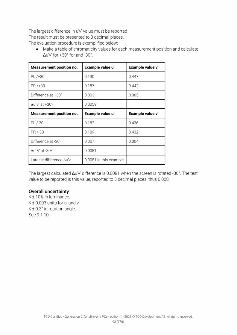
The largest difference in u'v' value must be reportedThe result must be presented to 3 decimal places.The evaluation procedure is exemplified below:
● Make a table of chromaticity values for each measurement position and calculateΔu'v' for +30° for and -30°.
Measurement position no. Example value u' Example value v'
PL /+30 0.190 0.447
PR /+30 0.187 0.442
Difference at +30º 0.003 0.005
Δu' v' at +30º 0.0059
Measurement position no. Example value u' Example value v'
PL /-30 0.182 0.436
PR /-30 0.189 0.432
Difference at -30º 0.007 0.004
Δu' v' at -30º 0.0081
Largest difference Δu'v' 0.0081 in this example
The largest calculated Δu'v' difference is 0.0081 when the screen is rotated -30°. The testvalue to be reported is this value, reported to 3 decimal places, thus 0.008.
Overall uncertainty≤ ± 10% in luminance.≤ ± 0.003 units for u' and v'.≤ ± 0.3° in rotation angle.See 9.1.10
TCO Certified - Generation 9, for all-in-one PCs - edition 1 - 2021 © TCO Development AB. All rights reserved.93 (176)

5.7 Color grayscale linearityBackgroundA well-tuned color grayscale is the basis for good color rendering of the screen. This ismeasured by comparing steps in a grayscale on the screen. To enable correct colorinterpretation, each grayscale step should have similar color hues. To avoid confusion for theuser, only the luminance should vary.
DefinitionColor grayscale linearity is the capability of the screen to maintain the same u',v' coordinatesof a grayscale pattern at all grayscale levels. Only the luminance should change from onegrayscale step to the next.
ApplicabilityDisplays and all-in-one PCs.
References5.4, 5.6, 5.18, 5.23, 5.26-5.29.
5.7.1 MandateΔu'v' ≤ 0.020 between 28 evenly distributed grayscale levels combinations.
Table color grayscale linearity 1Maximum u´v´difference
Grayscale 255 225 195 165 135 105 75 45255 0225 0.020 0195 0.020 0.020 0165 0.020 0.020 0.020 0135 0.020 0.020 0.020 0.020 0105 0.020 0.020 0.020 0.020 0.020 075 0.020 0.020 0.020 0.020 0.020 0.020 045 0.020 0.020 0.020 0.020 0.020 0.020 0.020 0
Submit the following together with the application to TCO Development:1. A copy of the test report(s), and a copy of the verification report(s) from a verifier
approved by TCO Development.2. The largest Δu'v’ measurement must be reported in TCO Certified Portal.
TCO Certified - Generation 9, for all-in-one PCs - edition 1 - 2021 © TCO Development AB. All rights reserved.94 (176)

5.7.2 ClarificationPreparations for testing
● All necessary preparations described in 9.1 and 9.2 must be done.● A TCO Certified default test image, as shown in figure 9.1.7, must be used for this
measurement.● The measurement area must have a size that is 4% of the active screen size and have
the following RGB settings: R=G=B= 255, 225, 195, 165, 135, 105, 75, 45.
EquipmentSpectroradiometer with a capacity to present u' and v' coordinates with at least 3 decimals.
Test methodThe instrument must be directed orthogonally towards the center of the measurement area,from the distance described in 9.2.5. Measure the chromaticity coordinates at the center ofthe measurement area for each grayscale step specified above. Change the grayscale of thearea for each measurement.
Test evaluationA spreadsheet is available on tcocertified.com, which will calculate the ∆ u’ v’ differencesbetween all the grayscale levels according to the equation:
∆𝑢'𝑣' = (𝑢'𝐴
− 𝑢'𝐵
)2
+ (𝑣'𝐴
− 𝑣'𝐵
)2
Fill in the chromaticity values of u’ and v’ for each measured grayscale step into thecorresponding cells of the spreadsheet.
Overall uncertainty≤ ± 10% in luminance.≤ ± 0.003 units for u' and v'.See 9.1.10
TCO Certified - Generation 9, for all-in-one PCs - edition 1 - 2021 © TCO Development AB. All rights reserved.95 (176)

5.8 Luminance levelBackgroundPoor screen luminance can lead to low contrast, poor readability and color discrimination,which may cause misinterpretations and eye strain. Therefore, it is important that theluminance levels can be set both high and low enough, with respect to the ambient lighting.
DefinitionLuminance being emitted from a particular area is a measure of the luminous intensity perunit area of light travelling in a given direction and falls within a given solid angle.The unit of luminance is candela per square meter (cd/m2)
ApplicabilityDisplays and all-in one PCs.
References5.3-5.5, 5.7-5.11.
5.8.1 MandateThe following conditions must be fulfilled:
● The luminance at default setting must be ≥ 150 cd/m2
● The maximum luminance must be ≥ 200 cd/m2
● The minimum luminance must be ≤ 100 cd/m2
Submit the following together with the application to TCO Development:● A copy of the test report(s), and a copy of the verification report(s) from a verifier
approved by TCO Development.● The maximum and minimum luminance must be reported in TCO Certified Portal
5.8.2 ClarificationPreparations for testing
● All necessary preparations described in 9.1 and 9.2 must be done.● The TCO Certified default test image with an 18 step grayscale as shown in figure
Luminance level 1 must be used for luminance level measurement.
TCO Certified - Generation 9, for all-in-one PCs - edition 1 - 2021 © TCO Development AB. All rights reserved.96 (176)

Figure Luminance level 1. TCO Certified default test image with the 18-step grayscaleinserted.
● The measurement position PC must be at the center of the measurement area withoutline borders, have an RGB setting of 255, 255, 255, and be positioned at the center ofthe screen. The background must be RGB 102,102,102.
● Reset the display to its default setting. Check that the luminance is ≥ 150 cd/m2.
The following evaluations must be carried out orthogonally to the screen surface.● To achieve the maximum luminance, proceed as follows:
Use the TCO Certified default test image with an 18 step grayscale pattern presentedon the screen. From the default setting, adjust the controls on the display to achieve ashigh luminance as possible with an acceptable image quality. The image quality isconsidered acceptable if at least 15 of the 18 grayscale steps are visible. Check thatthe display has a luminance of ≥ 200 cd/m2.
● Reset the display to its default setting. From the default setting, adjust the controls onthe display to achieve as low luminance as possible with an acceptable image quality.The image quality is considered acceptable if at least 15 of the 18 grayscale steps arevisible. Check that the display has a luminance of ≤ 100 cd/m2.
● If it difficult to visually determine if 15 of the 18 grayscale steps are visible, then thedisplay must conform with the grayscale gamma curve criteria in the max and minluminance setting.
● After this test is completed the display must be put back in its default mode bypressing a reset button or similar. After each reset, the display has to stabilize beforeother test measurements are made.
EquipmentLuminance meter or spectroradiometer.
TCO Certified - Generation 9, for all-in-one PCs - edition 1 - 2021 © TCO Development AB. All rights reserved.97 (176)

Test methodThe luminance at the center of the white measurement area must be measured with theluminance meter directed orthogonally to the measurement area as described in 9.2.5.
Test evaluationThe measured luminance is the required value. The luminance must be reported with nodecimal places.
The measured luminance, contrast and brightness settings for all conditions must be noted inthe test report. The preset CCT in default setting must also be noted.
Overall uncertainty≤ ± 10 % in luminance.See 9.1.10
TCO Certified - Generation 9, for all-in-one PCs - edition 1 - 2021 © TCO Development AB. All rights reserved.98 (176)
5.9 Luminance uniformityBackgroundPoor luminance uniformity can locally affect the contrast and consequently the readability ofinformation on the display. The areas of deviating luminance can have different sizes andcause varying contour sharpness.
DefinitionLuminance uniformity is the capacity of the display to maintain the same white luminancelevel over the whole active screen area. The luminance uniformity is defined as the ratio ofmaximum to minimum luminance within the fully active screen area.
ApplicabilityDisplays and all-in-one PCs.
References5.3-5.10, 5.12-5.15.
5.9.1 MandateLuminance variation across the active screen, Lmax : Lmin must be ≤ 1.50.
Submit the following together with the application to TCO Development:● A copy of the test report(s), and a copy of the verification report(s) from a verifier
approved by TCO Development.● The Luminance variation must be reported in TCO Certified Portal
5.9.2 ClarificationPreparations for testing
● All necessary preparations described in 9.1 and 9.2 must be done.● The entire active area of the screen must be white and the display color setting must
be RGB 255, 255, 255.
EquipmentLuminance meter or spectroradiometer.
Test methodThe luminance must be measured orthogonally to the display screen plane at nine points. Thefour corner positions (1, 3, 7 and 9) are measured 1º from the edges of the screen as shown infigure luminance uniformity 1. The four side positions (2, 4, 6 and 8) are measured on themiddle of the side, 1º from the edge. Finally, the center position (5) is measured. This meansthat all measurement points have 1/2º marginal to the edges if the measurement area of theinstrument is 1º.
TCO Certified - Generation 9, for all-in-one PCs - edition 1 - 2021 © TCO Development AB. All rights reserved.99 (176)

The luminance uniformity must also be evaluated visually by the technician in order to find anydark or bright areas outside of the nine default positions. If a significantly bright or dark areais found, these measuring points must also be measured and used to evaluate the luminanceuniformity.
The conditions for luminance measurement in the corner positions and the distribution ofother measurement points are illustrated in figure luminance uniformity 1.
Figure luminance uniformity 1 Measurement positions for the measurement of luminanceand color uniformity.
Test evaluationThe luminance uniformity must be reported as the ratio between the highest and the lowestmeasured luminance values. The result must be presented to 2 decimal places.
Overall uncertainty≤ ± 10 % in luminance.≤ ± 0.1 unit in luminance uniformity.See 9.1.10
TCO Certified - Generation 9, for all-in-one PCs - edition 1 - 2021 © TCO Development AB. All rights reserved.100 (176)

5.10 Luminance uniformity — angular-dependenceBackgroundThe luminance of a display may be angular-dependent which means that screen luminancedecreases when the display is viewed slightly from the side, either horizontally or vertically.This can have a negative effect on contrast and can affect the readability of the display.
DefinitionLuminance uniformity – angular dependence, is the capacity of the display to maintain acertain luminance level irrespective of the viewing direction. The angular-dependentluminance uniformity is defined as the ratio of maximum luminance to minimum luminance inthe specified measurement areas.
ApplicabilityDisplays and all-in-one PCs.
References5.7, 5.10-5.15.
5.10.1 Mandate1. In landscape mode, when the screen is rotated around the vertical axis through the
center of the screen the mean value of the Lmax to Lmin ratios at ±30° must be ≤ 1.73.2. In landscape mode, when the screen is rotated around the horizontal axis through the
center of the screen, the largest value of the Lmax to Lmin ratios at ±15° must be ≤ 1.73.
Submit the following together with the application to TCO Development:● A copy of the test report(s), and a copy of the verification report(s) from a verifier
approved by TCO Development.
5.10.2 ClarificationPreparations for testing
● All necessary preparations described in 9.1 and 9.2 must be done.● Luminance values must be measured at five different positions on the screen as
shown in figure luminance uniformity - angular-dependence 1. Each measurementposition must present white RGB 255, 255, 255 measurement areas (4% of the activescreen size) without line borders.
● The background must be RGB 102,102,102.● The luminance meter must be positioned and directed orthogonally to the screen
center-point as described in 9.2.5
TCO Certified - Generation 9, for all-in-one PCs - edition 1 - 2021 © TCO Development AB. All rights reserved.101 (176)

Figure: luminance uniformity - angular-dependence 1. Measurement positions for luminanceuniformity - angular dependence.
EquipmentLuminance meter.
Test method (steps)1. The luminance meter must always be directed towards a measurement point and
rotated around a fixed vertical axis, (or horizontal axis for the tilt measurement)through the focal point of its front lens with a distance as described in 9.2.5.
2. In landscape mode the display must be rotated +30 degrees around a vertical axisthrough the display-glass center-point and the luminance at positions PL and PR,(LPL/+30/0 and LPR/+30/0 respectively) must be recorded. See figure luminance uniformity- angular-dependence 2.
3. In landscape mode the display must then be rotated -30 degrees around the verticalaxis through the display-glass center-point and the luminance at positions PL and PR
(LPL/-30/0 and LPR/-30/0 respectively) must be recorded. See figure luminance uniformity -angular-dependence 2.
4. In landscape mode the display must then be tilted +15 degrees backwards around ahorizontal axis through the display-glass center-point and the luminance at positionsPT and PB (LPT/0/+15 and LPB/0/+15 respectively) must be recorded. See figure luminanceuniformity - angular-dependence 3.
5. In landscape mode the display must then be tilted -15 degrees forwards around ahorizontal axis through the display-glass center-point and the luminance at positionsPT and PB (LPT/0/-15 and LPB/0/-15 respectively) must be recorded. See figure luminanceuniformity - angular-dependence 3.
TCO Certified - Generation 9, for all-in-one PCs - edition 1 - 2021 © TCO Development AB. All rights reserved.102 (176)

6. The measurements to be carried out are summarized in table luminance uniformity -angular-dependence 4. The steps numbers in the step column correspond with thetest method paragraphs.
Figure luminance uniformity - angular-dependence 2. Top view of test set-up when the displayis rotated ±30 degrees. The + rotation is defined clockwise.
TCO Certified - Generation 9, for all-in-one PCs - edition 1 - 2021 © TCO Development AB. All rights reserved.103 (176)

Figure luminance uniformity - angular-dependence 3. Side view of the test set-up when thedisplay is tilted ±15°. The + rotation is defined as backwards.
Table luminance uniformity - angular-dependence 4.Test method step(reference above)
Landscape mode Screenrotation
Screentilt
Measuring pointsPL PR PT PB
Step 2Horizontal direction(turned aroundvertical axis)
+30° 0° X X
Step 3Horizontal direction(turned aroundvertical axis)
-30° 0° X X
Step 4Backwards tilt =(turned around thehorizontal axis)
0° +15° X X
Step 5Forwards tilt =(turned around thehorizontal axis)
0° -15° X X
Test evaluationThe luminance uniformity for angular dependence must be calculated as follows:
● In landscape mode, for the horizontal direction, (turned around the vertical axis)measurement presented in table luminance uniformity - angular-dependence 4 (teststep 2 and 3). A ratio between the two measured luminances must be calculated. Thisratio, or its inverse if it has a higher value, must be reported as the requested Lmax toLmin luminance uniformity in mandate 1. The requirement is on the mean value of thetwo ratios +30° and -30°. The result must be presented to 2 decimal places.
● In landscape mode, for the vertical direction (turned around the horizontal axis). Tiltbackwards and tilt forwards +15° test step 4 and 5. A ratio between the two measuredluminances must be calculated. This ratio, or its inverse if it has a higher value, mustbe reported as the requested Lmax to Lmin luminance uniformity in mandate 2. Therequirement is on the larger of the two ratios +15° and -15°. The result must bepresented to 2 decimal places.
Overall uncertainty≤ ± 10 % in luminance.≤ ± 0.3° in rotation angle.≤ ± 0.1 unit in luminance uniformity.See 9.1.10.
TCO Certified - Generation 9, for all-in-one PCs - edition 1 - 2021 © TCO Development AB. All rights reserved.104 (176)

5.11 Luminance contrast – charactersBackgroundThe degree of contrast is important for readability and for distinguishing one character fromanother.
DefinitionLuminance contrast – characters are the capacity of the display to maintain a high luminancedifference between a bright background and dark characters or parts of characters over thewhole active area.Luminance contrast – characters are expressed as the ratio of the Lmax to Lmin difference overthe sum of Lmax and Lmin, in accordance with Michaelson’s formula.
ApplicabilityDisplays and all-in-one PCs.
References5.3, 5.4, 5.10, 5.12-5.14, 5.16-5.18.
5.11.1 MandateThe luminance contrast must be ≥ 0.70 measured orthogonally to the screen.
Submit the following together with the application to TCO Development:● A copy of the test report(s), and a copy of the verification report(s) from a verifier
approved by TCO Development.● The luminance contrast must be reported in TCO Certified Portal
5.11.2 ClarificationPreparations for testing
● All necessary preparations described in 9.1 and 9.2 must be done.● A micro-photometer for luminance measurement must be aligned orthogonally to the
display surface.● The test images must be presented in a pixel matched way. (One program that does
this up to 8-bit color is Microsoft Paint.)
EquipmentA micro-luminance meter such as an array photodetector capable of measuring luminance onstructures ≤ 0.02 mm. Measurement requirements are given in section 9.2.2.
TCO Certified - Generation 9, for all-in-one PCs - edition 1 - 2021 © TCO Development AB. All rights reserved.105 (176)

Test methodThis measurement is a modified version of the measurements in IDMS 7.2 and IDMS 7.8.
By visual evaluation of the standard test measurement position, the technician must searchfor and locate visual stripes, or patches, that clearly influence the contrast of characters oreven parts of characters. If patches with significantly lower contrast are found, they must begeometrically referenced from the upper left corner of the active image and the position mustbe reported in the test report. If no such position is found, the default test position is thecenter of the screen. If one position is found that does not fulfil the mandate, there is no needto make further measurements.
With an array or scanning light measuring device, obtain the luminance profile of the verticalblack-pixel line and the corresponding white region. Obtain the net signal S as a function ofdistance with any background subtracted (this is the background inherent in the detector if anonzero signal exists for no light input). A correction for veiling glare must be made. See thefigure below for an illustration of the pixel configuration and data. 12 consecutive pixel rowsmust be used for integration in vertical direction to get a one-dimensional intensity signal.
Here, the 1-1-1-1 patterns must be used, i.e. the 6-groups with the highest resolution. Insideeach group, the pattern with the worst measured performance must be chosen.
Perform a running window average (moving box-car filter) of the luminance profile where theaveraging window width is as close as possible to the pixel pitch as rendered by the lightmeasuring device. There should be at least ten or more detector pixels per display pixel. Forexample, if an array detector is used and with the magnification of the imaging lens there are53.4 array pixels which cover the display pixel pitch, then the running average window width is53 array pixels wide.
From the resulting modulation curve, determine (1) the net intensity level of the vertical blackline SK = Sd – Sg, where Sd is the minimum intensity level (dim) of the black line generated bythe product, Sg is the ground level, and (2) the net intensity level of the white line SW = Sh – Sg,where Sh is the maximum intensity level (high) of the white line generated by the product.Compute the resolution contrast ratio as, C= (SW-SK)/(SW+SK).
TCO Certified - Generation 9, for all-in-one PCs - edition 1 - 2021 © TCO Development AB. All rights reserved.106 (176)

Figure Luminance contrast - characters 1: Measurement principle (from IDMS 7.2).In summary:SK = Sd-Sg (1)SW=Sh-Sg (2)C= (SW-SK)/(SW+SK)
Then perform the same operation but in vertical mode for the other set of grille patterns.Record the contrast values for both directions.
Test picture: “WGrille pattern” with the same resolution as the display.
Test evaluation● C must be ≥0.70.● The lowest luminance contrast found must be reported.● The result must be presented to 2 decimal places.
Overall uncertainty≤ ± 0.05 in contrast.The misalignment between the screen surface normal and the optical axis of the luminancemeter must be ≤ 0.3°.See 9.1.10
TCO Certified - Generation 9, for all-in-one PCs - edition 1 - 2021 © TCO Development AB. All rights reserved.107 (176)

5.12 Luminance contrast – angular dependenceBackgroundFor displays, the luminance and consequently the contrast of the display may beangular-dependent. The luminance variations can influence both the bright white and the darkareas of the screen, causing a change in contrast. This can have a negative effect on thereadability of the display.
DefinitionLuminance contrast – angular dependence, is the capability of the display to maintain thesame white/black contrast regardless of the direction from which the screen is viewed.Luminance contrast – angular dependence, is expressed as the ratio of the Lmax to Lmin
difference over the sum of Lmax and Lmin, in accordance with Michaelson’s formula. It ismeasured at two different angles.
ApplicabilityDisplays and all-in-one PCs.
References5.4, 5.12, 5.15-5.19.
5.12.1 MandateIn landscape mode, the luminance contrast-angular dependence must be ≥ 0.80 at ± 30°horizontally from the viewing direction (rotated around the vertical axis through the center ofthe screen).
Submit the following together with the application to TCO Development:● A copy of the test report(s), and a copy of the verification report(s) from a verifier
approved by TCO Development.● The luminance contrast-angular dependence must be reported in TCO Certified Portal.
TCO Certified - Generation 9, for all-in-one PCs - edition 1 - 2021 © TCO Development AB. All rights reserved.108 (176)

5.12.2 ClarificationPreparations for testing
● All necessary preparations described in 9.1 and 9.2 must be done.● A TCO Certified default test image, as shown in figure 9.1.7, must be used for this
measurement.● The measurement area must have each of the following RGB settings: (RGB 255, 255,
255) and (RGB 0, 0, 0).
EquipmentLuminance meter or spectroradiometer.
Test method● The luminance meter must be positioned and directed orthogonally to the screen
center-point as described in 9.2.5.● The display must be rotated around a vertical axis through the screen front center,
changing the azimuth angle to + 30°. The luminance of the white measurement areaLW+30 and the luminance when the measurement area is black Lk+30 at the center mustbe recorded.
● Finally the azimuth angle of the screen must be changed to -30°and the newmeasurements LW/-30 and Lk/-30 taken.
Test evaluationThe luminance contrast values C+30 and C-30 must be calculated using the formula
𝐶 =𝐿
𝑊 − 𝐿
𝐾
𝐿𝑊
+ 𝐿𝐾
Of C+30 and C-30, only the lowest value must be reported as the luminance contrast.
Overall uncertainty≤ ± 10% in luminance.See 9.1.10
TCO Certified - Generation 9, for all-in-one PCs - edition 1 - 2021 © TCO Development AB. All rights reserved.109 (176)

5.13 Black levelBackgroundIt is important that a display can produce a black level dark enough to show shadow details inpictures at high and low white luminance levels. The black level is also important for achievinga good contrast ratio.
DefinitionBlack level is the capacity of the display to maintain a good reproduction of black even whenits white luminance is high.
ApplicabilityDisplays and all-in-one PCs.
References5.6.
5.13.1 MandateThe luminance of black must be ≤ 2 cd/m2 at a white luminance setting of ≥ 200 cd/m2.
Submit the following together with the application to TCO Development:● A copy of the test report(s), and a copy of the verification report(s) from a verifier
approved by TCO Development.● The measured luminance must be reported in TCO Certified Portal.
5.13.2 ClarificationPreparations for testing
● All necessary preparations described in 9.1 and 9.2 must be done.● The TCO Certified default test image with an 18-step grayscale as shown in figure
luminance level 1 or alternative the larger measurement area image also described in9.1.7 must be used for luminance level measurement.
● The measurement position PC must be at the center of the measurement area withoutline borders, have an RGB setting of 0, 0, 0, and be positioned at the center of thescreen. Alternatively, a measurement area with a size that is 80% of the active screensize may be used.
● The black level must be tested at maximum luminance, i.e., ≥ 200 cd/m2.● To achieve the maximum luminance, proceed as follows:
Use the TCO Certified default test image with an 18-step grey scale pattern presentedon the screen. From the default setting, adjust the controls on the display to achieve ashigh luminance as possible with an acceptable image quality. The image quality isconsidered acceptable if at least 15 of the 18 grey scale steps are visible. Themaximum luminance level must be ≥ 200 cd/m2.
TCO Certified - Generation 9, for all-in-one PCs - edition 1 - 2021 © TCO Development AB. All rights reserved.110 (176)

● If it is difficult to visually determine if 15 of the 18 grey scale steps are visible, then thedisplay must conform with the grayscale gamma curve criteria in the max luminancesetting.
● Change the color of the white measurement area in the test image to black (RGB:0,0,0) and measure the luminance of the black area, check that it is ≤ 2 cd/m2.
EquipmentLuminance meter or spectroradiometer.
Test methodThe luminance at the center of the black measurement area must be measured with theluminance meter directed orthogonally to the measurement area as described in 9.2.5.
Test evaluationThe measured luminance is the required value. The luminance must be reported to onedecimal place.
Overall uncertainty≤ ± 10 % in luminance.See 9.1.10
TCO Certified - Generation 9, for all-in-one PCs - edition 1 - 2021 © TCO Development AB. All rights reserved.111 (176)

5.14 Grayscale gamma curveBackgroundA calibrated gamma curve makes it easier to distinguish between similar light levels. Awell-tuned grayscale is the basis for accurate detail rendering of any imaging device. Thegrayscale rendering is measured by comparing a set number of steps in a grayscale in the testimage. In order to give accurate rendering of the grayscale of the original image, eachgrayscale step, regardless of gray level, must have a luminance level close to what is specifiedby the common standard sRGB.
DefinitionGrayscale gamma curve is the capability of the imaging device to maintain the originalgrayscale luminance or a grayscale pattern at all tested grayscale levels.
ApplicabilityDisplays and all-in-one PCs.
References5.6, 5.17, 5.20-5.25.
5.14.1 MandateThe different grayscale luminance levels must be within the max and min levels specified inthe table below, where 100% is the luminance level measured for white: RGB 255, 255, 255.
graylevel LsRGB Lmin Lmax
% % %255 100 100,0 100,0225 75 70 93195 55 46 68165 38 29 49135 24 17 36105 14 8 2475 7 3 1445 3 1 7
Submit the following together with the application to TCO Development:● A copy of the test report(s), and a copy of the verification report(s) from a verifier
approved by TCO Development.
5.14.2 ClarificationPreparations for testing
● All necessary preparations described in 9.1 and 9.2 must be done.
TCO Certified - Generation 9, for all-in-one PCs - edition 1 - 2021 © TCO Development AB. All rights reserved.112 (176)
● A TCO Certified default test image, as shown in figure 9.1.7, must be used for thismeasurement.
● The measurement area must have each of the following RGB settings: R=G=B=255,225, 195, 165, 135, 105, 75 and 45.
EquipmentLuminance meter or spectroradiometer.
Test methodMeasure the luminance at the center of the measurement area for each grayscale settingspecified above. Change the grayscale of the area for each measurement.
Comments on the limits tolerance from the sRGB curveA linear tolerance has been applied symmetrically around the sRGB gamma curve. However,as many displays on the market today have a somewhat S-shaped gamma curve, a“S-correction” has been added to the linear tolerance on the gamma level 225 and 195.
This correction has been determined based on statistics from measured displays. TCODevelopment may decide to remove this “S-correction” in the next generation of this criteriadocument.
Overall uncertainty≤ ± 10 % in luminance.See 9.1.10
TCO Certified - Generation 9, for all-in-one PCs - edition 1 - 2021 © TCO Development AB. All rights reserved.113 (176)

6 Product lifetime extensionIT products and the circular economyThe concept of a circular economy is one that moves away from the linear “take, make anddispose” approach to products, to an economy that is more regenerative, and decoupleseconomic activity from the consumption of finite resources. For products, a move to a morecircular approach means designing out waste from the product ecosystem, and keepingproducts and materials in their intended use longer.
Today, too many IT products are discarded prematurely because of components orperformance aspects that could have been upgraded or repaired. There is also a growingmarket for second hand use of IT products, which also allows computers and otherelectronics to stay in use longer.
The best way to begin taking a more circular approach to the production and consumption ofIT products, is extending their usable life. Product reuse is also more resource efficient thanremanufacturing and recycling. For the IT industry, this means designing products that aredurable, built to last, upgradeable and repairable, making them more attractive for reuse orsecondary markets.
TCO Certified — extending product life, upgradability, durability
We believe that a more circular approach to IT products is critical in the drive toward anenvironmentally and socially responsible life cycle. Therefore, in TCO Certified, generation 9,we have included criteria that enable and promote product lifetime extension.
TCO Certified - Generation 9, for all-in-one PCs - edition 1 - 2021 © TCO Development AB. All rights reserved.114 (176)

6.1 Product warrantyBackgroundBy extending product lifetime, natural resources are used more efficiently and the pollution toair, water and soil is reduced. A precondition for an extended product lifetime is that theproduct is of high quality. A product warranty provides the brand owner with an economicincentive to design a durable product that lasts longer.
DefinitionsBrand owner: The company or organization owning or controlling the brand name.Brand name: The name or sign, including but not limited to a trademark or company name,used to identify, amongst users and customers, the manufacturer or seller of a product.Product warranty: Is an agreement where the brand owner offers to repair or replace brokenproducts at no charge.
ApplicabilityAll product categories.
6.1.1 MandateThe brand owner must:
● Provide a product warranty for at least one year,AND
● Provide information about the minimum product warranty period for the product
covering all markets where the product is sold.
Submit the following to an approved verifier:● A completed and signed brand owner product form (chapter 11.4).
Submit the following together with the application to TCO Development:● A copy of the verification report(s) from a verifier approved by TCO Development.
Clarification of sustainability performance indicator(s)One or more “sustainability performance indicators” (chapter 1.3) are collected for thiscriterion. There is no mandatory level for these indicators but they must be verified andreported according to the description below.
TCO Certified - Generation 9, for all-in-one PCs - edition 1 - 2021 © TCO Development AB. All rights reserved.115 (176)

Warranty period (Class A-G)The minimum number of years the whole product is covered by warranty
● Class A - Product warranty for at least 7 years, covering all markets where the productis sold
● Class B - Product warranty for at least 6 years, covering all markets where the productis sold
● Class C - Product warranty for at least 5 years, covering all markets where the productis sold
● Class D - Product warranty for at least 4 years, covering all markets where the productis sold
● Class E - Product warranty for at least 3 years, covering all markets where the productis sold
● Class F - Product warranty for at least 2 years, covering all markets where the productis sold
● Class G - Product warranty for at least 1 years, covering all markets where the productis sold
Verification: Documentation proving the product warranty period, covering all markets wherethe product is sold. If product components have different warranty periods, the worst casescenario (least number of years) must be reported.
The following SPI(s) is not required for compliance with TCO Certified. If no information isprovided the product will receive the lowest classification by default.
Extended warranty availability (Class A-G)The maximum number of years the product warranty can be extended to covering the wholeproduct.
● Class A - Extended warranty for the product is available for 7 years or more on allmarkets where the product is sold
● Class B - Extended warranty for the product is available for at least 6 years on allmarkets where the product is sold
● Class C - Extended warranty for the product is available for at least 5 years on allmarkets where the product is sold
● Class D - Extended warranty for the product is available for at least 4 years on allmarkets where the product is sold
● Class E - Extended warranty for the product is available for at least 3 years on allmarkets where the product is sold
● Class F - Extended warranty for the product is available for at least 2 years on allmarkets where the product is sold
● Class G - No information provided
Verification: Documentation proving the maximum availability of an extended warranty forthe product for all markets where the product is sold. If product components have differentwarranty periods, the worst case scenario (least number of years) must be reported.
TCO Certified - Generation 9, for all-in-one PCs - edition 1 - 2021 © TCO Development AB. All rights reserved.116 (176)

Public repair policy (A-C)● Class A
○ Product repair is favored before product replacement.○ A repair policy is publicly available.
● Class B○ No policy on product repair vs. replacement
● Class C○ No information provided
Verification: A link to a Public policy proving the type of repair policy.
TCO Certified - Generation 9, for all-in-one PCs - edition 1 - 2021 © TCO Development AB. All rights reserved.117 (176)

6.2 Replaceable componentsBackgroundExtending the lifetime of IT products is the most effective way to reduce their environmentalimpact. Components that often break or become outdated may limit the total lifespan of theproduct and must be replaceable. By making these critical replaceable components availableand providing the user with clear instructions on how to exchange them, IT-products can livelonger.
DefinitionsCPU: Central processing unit.GPU: Graphics processing unit.RAM: Random access memory.Storage: Any computing hardware that is used for storing, porting, and extracting data filesand objects, including temporary and permanent storage of information (SSD, HDD, RAM).Display assembly: Main display panel.All batteries: Defined as all batteries with one or more cells that are installed in the product.System board: Also referred to as the motherboard.Keyboard: Built-in keyboard.External/Internal PSU: The power supply unit used to convert AC to low voltage DC power forthe internal components of the product.Critical, replaceable components: Components that are crucial for the functionality and have ahigh risk of failing during normal use. Components that are defined as critical, replaceablecomponents (per product category) are listed in the clarifications section of this criterion.
ApplicabilityAll product categories.
References6.1, 6.2.
TCO Certified - Generation 9, for all-in-one PCs - edition 1 - 2021 © TCO Development AB. All rights reserved.118 (176)

6.2.1 Mandate1. The brand owner must provide a service manual describing how to replace at least all
critical replaceable components. The service manual must be available for anyone toread, free of charge in case the critical replaceable components are available foranyone to purchase or to the service network.
2. The brand owner must guarantee that, during the validity of the certificate, all criticalreplaceable components for the product type:, that are listed in the clarifications of thiscriterion;
○ are available for anyone to purchaseor
○ may be replaced by a service network for repair and maintenance of thecertified product on all markets where it is sold.
Submit the following to an approved verifier:● A completed and signed brand owner form (chapter 11.4)● A link to the service manual on the brand owner website or a pdf of the material that
will be published there during the validity of the certificate
Submit the following together with the application to TCO Development:● A copy of the verification report(s) from a verifier approved by TCO Development.
6.2.2 ClarificationReplaceable parts management
● The brand owner must provide a service manual including step-by-step instructionsand component descriptions for the disassembly and assembly.
○ External PSU, charger, and AC Adapters are exempted from the disassemblyinstructions.
○ If instructions on how to replace all critical replaceable components (listedbelow) are included in the user manual, no additional service manual is neededto comply with the mandate 6.2.1.
● A critical, replaceable component must be possible to replace with an equivalentcomponent. However, the replacement component does not have to be identical to theoriginal component.
● Instructions on how to replace the critical components must be available online duringthe validity of the certificate.
● Step-by-step instructions on how to replace soldered components does not need to belisted in the service manual (mandate 6.2.1)
● For data center products (Servers, Storage products, Network equipment), if one ormore critical replaceable component(s) are part of a controller canister or systemboard, the controller canister or system board must be treated as the criticalcomponent.
TCO Certified - Generation 9, for all-in-one PCs - edition 1 - 2021 © TCO Development AB. All rights reserved.119 (176)

● Headband cushions which are molded do not need to be replaceable. Headbandcushions designed to be snapped/mounted (for eg, with adhesive) shall bereplaceable.
Critical replaceable components:The critical replaceable components listed below must only be made available if they areincluded in the certified product.
DisplaysConnectivity cablesPower cablesExternal PSU
For SPI evaluation only:System board/motherboardDisplay panel assembly
TabletsBatteryDisplay Panel/display assemblyExternal/internal PSU
All-in-one PCsCPUExternal/internal PSUStorage (SSD, HDD, ODD)System memory (RAM)System board/motherboard
SmartphonesBatteryDisplay Panel/display assemblyCharger
NotebooksBatteryDisplay Panel/display assemblyStorage (SSD, HDD)System memory (RAM)External/internal PSUKeyboardSystem board/motherboard
HeadsetsBatteryExternal/internal PSUEarloopNeckbandEar tipsEar cushionsMicrophone shieldHeadband
DesktopsCPUGPU (PCIe)External/internal PSUStorage (SSD, HDD, ODD)System memory (RAM)System board/motherboard
ProjectorsThe light source (except lasers)FiltersExternal PSU
TCO Certified - Generation 9, for all-in-one PCs - edition 1 - 2021 © TCO Development AB. All rights reserved.120 (176)

ServersSystem boards(s)Storage (i.e. SSD, HDD)CPURAMNetwork devicePSUFan module(s)Connectivity cablesRack railsCable management arms
Storage productsSystem board(s)Storage (i.e. SSD, HDD)Storage controller (i.e. RAID controllers)PSUFan module(s)BatteriesConnectivity cablesRack railsCable management arms
Network equipmentSystem board(s)Storage (i.e. SSD, HDD)PSUFan module(s)Expansion module(s)I/O module(s)Connectivity cablesRack railsCable management arms
Component table
TCO Certified - Generation 9, for all-in-one PCs - edition 1 - 2021 © TCO Development AB. All rights reserved.121 (176)

Clarification of sustainability performance indicator (SPI)(s)One or more “sustainability performance indicators” (chapter 1.3) are collected for thiscriterion. There is no mandatory level for these indicators but they must be verified andreported according to the description below.
Replaceability and repairability of the productFor each critical component in the component table above, the following evaluation must becompleted to calculate the repairability and reusability of the product. The evaluation is basedon the standard EN 45554:2020 - General methods for the assessment of the ability to repair,reuse and upgrade energy-related products.
1. Fasteners and connectors (Class A-D)2. Necessary tools for repair/upgrade, (Class A-D)3. Availability of spare parts
a. Availability by target group (Class A-E)b. Duration of availability (Class A-D)
4. Types and availability of information - Availability of comprehensiveness (Class A-C)
1. Fasteners and connectors (Class A-D)The reusability of fasteners and connectors is interlinked with the repairability and reusabilityof products and components. Knowledge of type of fasteners can assist with the assessmentof tools and skills necessary for repair reuse or upgrade.Evaluation procedureThe assessment of the fasteners and connectors must be done from the start until thecomponent is removed. This means that if any other part needs to be removed before it ispossible to remove the critical component, then those steps must also be taken intoconsideration for the final score.
● Class A: Reusable○ An original fastening system that can be completely reused, or any elements of
the fastening system that cannot be reused are supplied with the new part forthe repair, reuse or upgrade process.
● Class B: Removable○ An original fastening system that is not reusable, but can be removed without
causing damage or leaving residue which hinders reassembly (in case of repairor upgrade) or reuse of the removed part (in case of reuse) for the repair, reuseor upgrade process.
● Class C: Neither removable nor reusable○ An original fastening system that is not removable and not reusable, as defined
above, for the repair, reuse or upgrade process.● Class D: No evaluation performed
TCO Certified - Generation 9, for all-in-one PCs - edition 1 - 2021 © TCO Development AB. All rights reserved.122 (176)

Example for a battery in a notebook:Example 1Step 1 - Remove eight screws to open the chassis - Class AStep 2 - Remove four screws and loosen the connector to the motherboard - Class AStep 3 - The battery can now be removed without using tools - Class ATotal score for battery component: Class A
Example 2Step 1 - Remove eight screws to open the chassis - Class AStep 2 - Remove four screws and loosen the connector to the motherboard - Class AStep 3 - The battery is glued with non-reusable adhesive - Class BTotal score for battery component: Class B
If a component is soldered to another component, it automatically receives Class C.
2. Necessary tools for repair/upgrade (Class A-E)The availability of tools necessary for repair, service or upgrade, are interlinked with theproduct lifetime. Without easy access to tools needed for repair, upgrade or service thelikelihood of these decrease. Therefore, it is important to make use of tools that are readilyavailable instead of using proprietary tools.
● Class A: Basic tools, no tools, provided tools○ Replacing critical components can be carried out without the use of any tools,
or with a tool or set of tools that is supplied with the product or spare part, orwith basic tools as listed in Table A.
○ All tools required must be listed in the service manual.
Tool type Reference
Screwdriver for slotted heads, crossrecess or for hexalobular recessheads
ISO, 2380, ISO, 8764, ISO 10664
Hexagon socket key ISO 2936
Combination Wrench ISO 7738
Combination pliers ISO 5746
Half round nose pliers ISO 5745
Diagonal cutters ISO 5749
Multigrip pliers(multiple slip joint pliers)
ISO 8976
Locking pliers
Combination pliers for wire strippingand terminal crimping
TCO Certified - Generation 9, for all-in-one PCs - edition 1 - 2021 © TCO Development AB. All rights reserved.123 (176)

Prying lever
Tweezers
Hammer, steel head ISO 15601
Utility knife cutter with snap offblades
Multimeter
Voltage tester
Soldering iron
Magnifying glass
Table A - Basic tools
● Class B: Other commercially available tools.○ Replacing critical components can be carried out with non-proprietary tools
that are not Class A.○ All tools required must be listed in the service manual.
Verification: The brand owner must include a link to a shop where the tools can be bought inthe service manual.
● Class C: Can be carried out with proprietary tools.○ The tools required to replace critical components can be carried out with use
of proprietary tools. These are tools that are not available for purchase by thegeneral public or for which any applicable patents are not available to licenseunder fair, reasonable, and non-discriminatory terms.
Verification: The brand owner must state in the service manual that the tools needed areproprietary.
● Class D: Not enough information, or not feasible with any existing tools.○ The tools listed in the service manual are not Class A, and no extra information
is made available on where usable tools can be purchased, or if they areproprietary.
or○ The tools required to replace the critical components are not listed in the
service manual.● Class E: No evaluation performed
TCO Certified - Generation 9, for all-in-one PCs - edition 1 - 2021 © TCO Development AB. All rights reserved.124 (176)

3. Availability of spare partsThe availability of spare parts is a prerequisite for a successful repair. Spare parts availabilityrefers to both the availability to various target groups and the availability over a specific periodof time. These two perspectives are assessed in sequence.
3.a. Availability by target group (Class A-E)● Class A: Publicly available● Class B: Available to independent repair service providers● Class C: Available to manufacturer-authorized repair service providers● Class D: Available to the manufacturer only● Class E: No spare parts available or no information on availability
Verification: The brand owner must pledge the availability of spare parts in the servicemanual.
3.b. Duration of availability (Class A-D)● Class A: Long-term availability (6 or more years)● Class B: Mid-term availability (4 or more years)● Class C: Short-term availability (2 or more years)● Class D: No information on duration of availability
Verification: The brand owner must pledge the minimum duration of availability for spareparts in the service manual.
4. Comprehensiveness of available information (Class A-C)The comprehensiveness of service information facilitates the possibility for repairs,maintenance and upgrades, which enables the extension of product lifetime.
● Class A: Comprehensive information availableA repair, reuse or upgrade process, for which the following information is available foranyone to read, free of charge:
○ Step-by-step disassembly instructions with identification of tools needed.○ Information on where to attain all tools needed for repair/upgrade.○ An overview of repair or upgrade services offered by the manufacturer.○ Troubleshooting charts.○ Circuit board schematics.(only main board)○ Functional specification of parts (e.g. resistance value of resistors).○ Recommended torque for fasteners.○ Diagnostic and error resetting codes.
or○ Appropriate formats for reporting comprehensive information can include
IEEE1874 (IEEE Standard for Documentation Schema for Repair and Assemblyof Electronic Devices).
TCO Certified - Generation 9, for all-in-one PCs - edition 1 - 2021 © TCO Development AB. All rights reserved.125 (176)

● Class B: Basic information availableA repair, reuse or upgrade process, for which the following information is available foranyone to read, free of charge:
○ Step-by-step disassembly instructions with identification of tools needed.○ Information on where to attain all tools needed for repair/upgrade.○ An overview of repair or upgrade services offered by the manufacturer.○ Troubleshooting charts.
● Class C: Limited information availableA repair, reuse or upgrade process, for which the following information is available foranyone to read, free of charge:
○ Step-by-step disassembly instructions with identification of tools needed.
Verification: Unless the brand owner provides documentation showing compliance withClass A or B, the product will be categorized as Class C.
TCO Certified - Generation 9, for all-in-one PCs - edition 1 - 2021 © TCO Development AB. All rights reserved.126 (176)

6.3 Standardized connectorsBackgroundBy using one standardized interface (USB Type-C) for charging and data transfer, fewer cablesneed to be manufactured and the re-use of chargers and data cables can increase. USBType-C is also designed to be more robust and future-proof than the existing USB Type-A andType-B. Therefore, using USB Type-C helps prevent problems with failing ports.
The connector can also enable features such as eGPU for notebooks that make it possible toupgrade the GPU performance with standalone graphics cards. This means that a user will beable to keep the same product for a longer time.
DefinitionsUSB Type-C: A 24-pin USB connector system with a horizontally symmetrical "reversible"connector.
ApplicabilityNotebooks, desktops, AIOs
6.3.1 MandateThe device must carry at least one USB Type-C connector that is backward compatible withUSB 2.0.
Submit the following to an approved verifier:● A completed and signed product form (chapter 11.3)
Submit the following together with the application to TCO Development:A copy of the verification report(s) from a verifier approved by TCO Development.
6.3.2 ClarificationProducts with no connectors are exempted from this criterion.
TCO Certified - Generation 9, for all-in-one PCs - edition 1 - 2021 © TCO Development AB. All rights reserved.127 (176)

6.4 Secure data removalBackgroundBy reusing IT products, their usable life can be extended which is an effective way of reducingtheir environmental impact. However, fear of confidential data leakage often preventscompanies and individuals from making their products available on the second-hand market.By providing software that wipes the storage of the device, the owner can more safelyrecirculate their product.
DefinitionsBrand owner: The company or organization owning or controlling the brand name.Brand name: The name or sign, including but not limited to a trademark or company name,used to identify, amongst users and customers, the manufacturer or seller of a product.Media sanitization: refers to a process that renders access to target data on the mediainfeasible for a given level of effort.NIST 800-88 Revision 1: Erasing a hard drive using the NIST 800-88 Revision 1 datasanitization method will prevent all software-based file recovery methods and hardware-basedrecovery methods from recovering data from the drive.
ApplicabilityNotebooks, network equipment, desktops, all-in-one PCs, servers, data storage products,smartphones and tablets.
Reference6.7.
6.4.1 MandateThe brand owner must provide a media sanitization solution, either by:
1. Pre-installing it on/in the product before it is shipped.2. providing the software for download on their webpage, free of charge.3. providing a direct link on their own webpage to an external webpage where the
software is available for download, free of charge.4. providing a remote secure data removal service upon request, free of charge.5. providing an on-site secure data removal service upon request, free of charge.
The selected media sanitization solution above must conform with the guidelines of NIST800-88 Revision 1, for the level of “Clear” in accordance with the products storage technology.Users must be able to use it at least once, free of charge.
OR
6. Pre-installed data encryption technologies that allow for erasure or removal of theencryption keys.
TCO Certified - Generation 9, for all-in-one PCs - edition 1 - 2021 © TCO Development AB. All rights reserved.128 (176)

Submit the following to an approved verifier:● A completed and signed product form (chapter 11.3).
Submit the following together with the application to TCO Development:A copy of the verification report from a verifier approved by TCO Development.
6.4.2 ClarificationWe accept “enhanced secure erase” as an option for ATA SSDs to comply with the level of"Clear" in NIST 800-88 Revision 1.
Clarification of sustainability performance indicator(s)One or more “sustainability performance indicators” (chapter 1.3) are collected for thiscriterion. There is no mandatory level for these indicators but they must be verified andreported according to the description below.
Media sanitization solution (Class A-B)● Class A - Media sanitization solution: 1 or 6● Class B - Media sanitization solution: 2, 3, 4 or 5
Compliance with EN 45554:2020 - A.4.11 Data management (Class A-B)This criterion can be used as verification of conformity with EN 45554:2020 A.4.11 Datamanagement:
● Class A - No data stored or built-in : media sanitization solution: 1● Class B - On request: media sanitization solution: 2, 3, 4 ,5
TCO Certified - Generation 9, for all-in-one PCs - edition 1 - 2021 © TCO Development AB. All rights reserved.129 (176)

7 Reduction of hazardous substancesHazardous substances in IT products: A human health and environmental riskChemicals and heavy metals used in IT products present a wide variety of human health andenvironmental hazards. Products may release dioxins and other highly toxic substances,which can persist in the natural environment and human body. Hazardous substances includeflame retardants and plasticizers contained in plastics and cables, and also processchemicals used in manufacturing
Risks include worker and environmental exposure in the manufacturing supply chainas well as during end of life handling when these harmful substances risk leaching outinto soil, water and air. Also, from a circularity perspective, contaminated materialscannot responsibly be reused in future products, and therefore risk being incineratedor discarded directly into the waste stream.
While some hazardous substances have been phased out through legislation orvoluntary initiatives, too little is known about what’s being used to replace them. Only asmall percentage of chemicals in use today have been evaluated for theirenvironmental and human health risk. Better knowledge and transparency aroundthese chemicals is needed, along with pathways for making safer substitutions.
Our approachCriteria in TCO Certified restrict the use of hazardous substances and drive a shifttowards greater transparency and use of safer alternatives. Criteria go beyond RoHSand cover heavy metals, halogens, non-halogenated flame retardants and plasticizers.
Criteria in chapter 7 focus on:● Reducing or eliminating the use of hazardous substances in IT products and their
packaging, beyond RoHS.● Identifying a pathway to safer alternatives to hazardous flame retardants, plasticizers
and process chemicals by requiring that these substances are independentlyassessed and benchmarked. The approved safer alternatives are presented on theTCO Certified Accepted Substance List.
TCO Certified - Generation 9, for all-in-one PCs - edition 1 - 2021 © TCO Development AB. All rights reserved.130 (176)

7.1 Heavy metalsBackgroundElectronic devices contain hazardous substances like heavy metals and brominated flameretardants. The effects of cadmium, mercury, lead and hexavalent chromium are welldocumented as substances hazardous both to human health and the environment. They maycause problems, both in the manufacturing phase where workers or the environment can beexposed, and at the material recovery, where uncontrolled recycling can cause the release oftoxins such as dioxins and furans.This criterion is harmonized with EU RoHS Directive (2011/65/EU), except that in TCOCertified, mercury is not allowed in lamps. As TCO Certified is a global certification, this alsoaffects products sold outside the EU.
ApplicabilityDisplays, notebooks, tablets, smartphones, desktops, all-in-one PC’s, headsets, servers,network equipment, data storage products.
References7.1, 7.2.
7.1.1 MandateThe product must not contain cadmium, mercury, lead and hexavalent chromium
Exemptions are according to EU Directive 2011/65/EU (RoHS) and the documents supportingthe directive except that mercury in lamps is not permitted.
The maximum concentration values tolerated by weight in homogeneous materials are 0.01%for cadmium, 0.1% for mercury, 0.1% for lead and 0.1% for hexavalent chromium according toEU RoHS Directive (2011/65/EU annex II) and the documents supporting the directive.
The limit value for batteries is 0.0005 % for mercury, 0.002 % for cadmium and 0.004 % leadper listed part, according to EU Directive 2006/66/EC.
Submit the following to an approved verifier:● A completed and signed product form (chapter 11.3).
Submit the following together with the application to TCO Development:● A copy of a verification report from a verifier approved by TCO Development.
TCO Certified - Generation 9, for all-in-one PCs - edition 1 - 2021 © TCO Development AB. All rights reserved.131 (176)

7.2 HalogensBackgroundHalogenated substances are often persistent and can bio-accumulate in living organisms.They are problematic from both a human health and environmental perspective throughoutthe product life cycle and should be phased out. Workers may be exposed duringmanufacturing. Substances risk leaking out into the natural environment at end of life. PVC isby far the most common halogen-containing plastic.
DefinitionsElectronic component is considered an individual part or combination of parts that, whentogether, perform a design function(s).Product housing is considered the external enclosure or casing that protects the internal partsof a product. This includes a product stand and external power supplies.Printed circuit board (PCB) or printed wiring board (PWB) laminate is a printed board thatprovides point-to-point connections.Power board or power PCB regulates the power leading to the device, converting alternatingcurrent to direct currentPolybrominated biphenyls (PBB) and polybrominated diphenyl ethers (PBDE) are restricted inthe EU RoHS Directive (2011/65/EU) due to the hazardous properties of these substances.Hexabromocyclododecane (HBCDD) has been identified as a substance of very high concernin accordance with EU REACH criteria due to PBT (persistent, bio accumulative, toxic)properties.
ApplicabilityAll product categories.
References7.2, 7.3.
7.2.1 Mandate1. Product housing above 0.5 grams and the power PCB laminate of the internal/external
power supply unit must not contain intentionally added (additive or reactive) flameretardants or plasticizers with halogenated substances.Exempted are all other parts, such as electronic components, other PCBlaminates and all kinds of cable insulation.
2. The product must not contain PBB, PBDE and HBCDD.No parts of the product are exempted.
3. The largest PCB by area in the power supply unit (internal/external) must be tested forbromine and chlorine, (see clarification below).
Maximum concentration values tolerated for a restricted substance (including decaBDE) is0.1% by weight of the material in homogeneous materials.
TCO Certified - Generation 9, for all-in-one PCs - edition 1 - 2021 © TCO Development AB. All rights reserved.132 (176)

Fluoroorganic additives, used to modify the dripping behavior of plastics in fire conditions orto improve the processing behavior, are exempted provided that they do not exceed 0.5% byweight of the material in homogeneous materials.Submit the following to an approved verifier:
● A completed and signed product form (chapter 11.3).● A copy of the test report(s) from any laboratory accredited according to ISO 17025
Submit the following together with the application to TCO Development:● A copy of the test report(s) from any laboratory accredited according to ISO 17025 and
a copy of the verification report(s) from a verifier approved by TCO Development.
7.2.2 ClarificationPoint 1 of the mandate applies to plastic product housing parts above 0.5 grams. Thisincludes the product stand and the plastic housing of the external power supply. The internalor external power supply socket or inlet is not included in the definition of product housing..The power board laminate of the internal or external power supply is the only PCB that ismandated due to the high risk for their being added flame retardants to this part. All otherPCBs inside the product are exempted.
Point 2 of the mandate applies to the whole of the product, including components, parts andraw materials in all assemblies and sub-assemblies, such as batteries, paint, surfacetreatment, plastics, electronic components and printed wiring boards.
Point 3 of the mandate applies to the testing for bromine and chlorine where the following isrequired:
The largest PCB by area in the power supply unit must be tested for bromine and chlorine. ThePCB must be tested in its final state with PCB laminates included but does not need to betested with electrical components attached. Testing must be conducted through either IECIEC 62321-3-1:2013, 62321-3-2:2020 or EN14582 by an ISO 17025 accredited laboratory.If the same PCB is used in multiple products, a test report may be used for multiple products iftraceability between the tested sample and the product is verified.
● If indications of bromine or chlorine >0.1% are discovered, the applicant must proceedwith additional testing in order to prove compliance with this criterion.
● If the concentration of detected substance is <0.1%, then no additional testing isneeded.
TCO Certified - Generation 9, for all-in-one PCs - edition 1 - 2021 © TCO Development AB. All rights reserved.133 (176)

7.3 Non-halogenated substancesBackgroundHazardous non-halogenated substances are problematic in the manufacturing and materialrecovery phases where workers and the environment can be exposed, leading to both humanhealth and environmental risks. The purpose of this criterion is to increase the knowledge ofwhich non-halogenated substances are used in certified products, how hazardous they are tohuman health and the environment, and to drive a shift toward less hazardous alternatives.This mandate uses the hazard assessment and decision logic framework GreenScreen® forSafer Chemicals, developed by the non-profit organization Clean Production Action (CPA).GreenScreen criteria are in line with international standards and regulations that assess thehuman health and environmental risks of chemicals. These include the Regulation on theclassification, labelling and packaging of substances and mixtures (CLP), GloballyHarmonized System of Classification and Labelling of Chemicals (GHS), OECD testingprotocols, European REACH Regulation that includes RoHs, POPs, SVHCs and the U.S. EPA’sDesign for Environment (DfE) Alternatives Assessment.
DefinitionsGreenScreen Profilers: Toxicology firms licensed by CPA to provide GreenScreen assessmentservices for a fee to clients.TCO Certified Accepted Substance List: Public list of independently assessed safer availablealternatives considering toxicity and functionality. Go to tcocertified.com.Clean Production Action (CPA). Developers of GreenScreen® for Safer Chemicals.Electronic component is considered an individual part or combination of parts that, whentogether, perform a design function(s) and are typically directly attached to a printed circuitboard. Internal and external power supplies are not included in the definition.Product housing is considered the external enclosure or casing that protects the internal partsof the product. This includes the product stand.
ApplicabilityAll product categories.
References7.4, 7.5, 7.6.
TCO Certified - Generation 9, for all-in-one PCs - edition 1 - 2021 © TCO Development AB. All rights reserved.134 (176)

7.3.1 Mandate● Product housing and printed circuit boards above 0.5 grams must only contain
intentionally added (additive or reactive) non-halogenated flame retardants that havebeen assigned a GreenScreen benchmark score of 2, 3 or 4 by a licensed GreenScreenProfiler and appear on the public TCO Certified Accepted Substance List. (Abenchmark U may only be accepted when the “worst case scenario” for data gaps isconsidered to be a benchmark 2 or above.)
● All substances of a mixture must be accounted for. Non-accepted substances mustnot exceed concentration levels of 0.1% by weight of the flame retardant.
● Exempted are all other parts, such as electronic components and all kinds of cableinsulation.
Submit the following to an approved verifier:● A completed and signed product form (chapter 11.3).
Submit the following together with the application to TCO Development:● A copy of a verification report from a verifier approved by TCO Development.● A document copy or access to a database copy of the certified assessment report
conducted and issued by a licensed GreenScreen Profiler.
7.3.2 ClarificationThe mandate applies to the product housing and printed circuit boards (PCBs) above theweight of 0.5 grams. This includes plastic housing of internal and external power supplies andtheir PCBs. PCBs that are exempted are those enclosed inside electronic components such asa HDD, SSD and ODD.
TCO Certified Accepted Substance ListNon-halogenated flame retardants can be used in certified products once they receive anaccepted benchmark and appear on the public TCO Certified Accepted Substance List. The listis dynamic, which allows new substances that have undergone a valid assessment to beadded. Accepted substances may be reassessed in light of new scientific findings. If anaccepted substance is reassessed and given a benchmark score lower than 2, TCODevelopment reserves the right to remove the substance from TCO Certified AcceptedSubstance List. Before a substance is removed from the list a sunset date (at least one year) isset and shown on the list. This is to give chemical and product manufacturers time to submitadditional information to improve the benchmark score or to transfer to an alternative on thelist. Product models that use a removed chemical but were certified before the sunset date arepermitted to keep their TCO Certified certificate. Models certified after the sunset date mayonly contain flame retardants or plasticisers that are listed on TCO Certified AcceptedSubstance List.Any spot checks by TCO Development will require manufacturers to disclose substancedetails being used in randomly chosen products. To verify that the obligations according tothis mandate are fulfilled CASNR disclosure and laboratory assessments of selected plasticparts will be conducted to assess the completeness, quality and validity of a benchmark score.
TCO Certified - Generation 9, for all-in-one PCs - edition 1 - 2021 © TCO Development AB. All rights reserved.135 (176)

TCO Development and Clean Production Action (CPA) must have access to a copy of theGreenScreen assessment report before the substance can be added to TCO CertifiedAccepted Substance List, available at tcocertified.com.
Conformity procedure● The applicant must contact relevant suppliers and ask them to confirm that the flame
retardants and plasticizers they use only include substances listed on TCO CertifiedAccepted Substance List.
● If all flame retardants and plasticizers only include substances on TCO CertifiedAccepted Substance List, complete the product form 11.3 and submit it to anapproved verifier. When the verifier considers all documentation to be compliant, theywill issue an environmental verification to the applicant.
● If any flame retardant or plasticizer is used that contains a substance that is above thethreshold level but doesn’t appear on TCO Certified Accepted Substance List, then itmust be added before approval can be given by a verifier. An extended time period tocomply can be applied for here (see “Applying for an extended period…” below).
Adding a substance to the TCO Certified Accepted Substance List:1. Contact TCO Development directly to see if we have any additional information on the
substance. Reasons for the substance’s absence can be that the substance hasreceived benchmark 1, that no assessment has been conducted or that it has abenchmark score U (unspecified), due to a high number of data gaps.
2. If TCO Development requires the substance to be benchmarked, we recommend thatyou contact your suppliers and inform them that the substance will need anassessment by a licensed GreenScreen Profiler. The list of licensed profilers can befound on the Clean Production Action website at greenscreenchemicals.org.
3. A draft report per substance (not per product) is assembled by the licensed profilerfrom the available information (literature search, structural similarity comparison,expert judgment).
4. It is the licensed profiler that sets the benchmark score per relevant substance, whichis valid for at least five years.
5. Benchmark reports must be submitted to TCO Development for final approval before asubstance is added to TCO Certified Accepted Substance List. A copy must also bemade available to CPA.
6. When the final approval is complete, TCO Development will add the substance to theTCO Certified Accepted Substance List, showing the substance’s name, CASRN, type,benchmark score, date of the assessment and profiler.
7. Once a substance is added to the list and the environmental verifier identifies them,then they will issue the environmental verification to the applicant (see above point 1:“If all flame retardants and plasticizers only include substances on TCO CertifiedAccepted Substance List the procedure is as follows”).
TCO Certified - Generation 9, for all-in-one PCs - edition 1 - 2021 © TCO Development AB. All rights reserved.136 (176)

Applying for an extended period of time to add a substance to TCO CertifiedAccepted Substance ListApplicants signing the mandate have the option to seek an extended period of time in order tocomplete assessments or substitute substances with unknown hazard levels. Upon requestfor an extension, the applicant is required to complete a risk assessment questionnaire andsubmit it to TCO Development. The risk assessment requires the applicant to clarify why anextension is necessary, provide information on the chemical and its substitute in question, andinclude a timeline for the assessment and/or substitution to be completed. If an extensionapplication is not granted, the applicant is required to ensure that all used flame retardants orplasticizers only include substances that are on TCO Certified Accepted Substance List beforean environmental verification can be issued for the product model by an environmental verifier.If the agreed extension due date is exceeded without conformity, then the environmentalverifier must contact TCO Development and a course of action will be decided after discussingthe issue with the applicant.
TCO Certified - Generation 9, for all-in-one PCs - edition 1 - 2021 © TCO Development AB. All rights reserved.137 (176)

7.4 PlasticizersBackgroundPlasticizers are increasingly associated with negative environmental and human healthimpacts. RoHs is a restricted substances list that, beginning in 2019, restricts the use of fourphthalates. TCO Development is committed to take a much broader approach by identifyingand restricting not only these four, but all substances of high concern used in IT products. Ourcriteria are therefore designed to make sure that replacement substances are independentlyassessed as safer alternatives, and that transparency increases. The full list of saferalternatives is available on tcocertified.com.
This mandate uses the hazard assessment and decision logic framework calledGreenScreen® for Safer Chemicals, developed by the non-profit organization CleanProduction Action (CPA).
GreenScreen criteria are in line with international standards and regulations that assesschemicals on their human health and environmental hazards. These include the Regulationon the classification, labelling and packaging of substances and mixtures (CLP), GloballyHarmonized System of Classification and Labelling of Chemicals (GHS), OECD testingprotocols, European REACH Regulation that includes RoHs, POPs, SVHCs and the U.S. EPA’sDesign for Environment (DfE) Alternatives Assessment .
DefinitionsPlasticizer: An additive to a polymer (plastic), to increase its flexibility, transparency, durability,or longevity.Phthalates: The most common type of plasticizer in PVC cables.Licensed profilers: Toxicology firms licensed by CPA to provide GreenScreen assessmentservices for a fee to clients.TCO Certified Accepted Substance List: Public list of independently assessed safer availablealternatives considering toxicity and functionality. Available at tcocertified.com.Clean Production Action (CPA). Developers of GreenScreen® for Safer Chemicals,Product housing is considered the external enclosure or casing that protects the internal partsof the product. This includes the product stand.Electronic component is considered an individual part or combination of parts that, whentogether, perform a design function(s) and are typically directly attached to a printed circuitboard. Internal and external power supplies are not included in the definition.
ApplicabilityAll product categories.
References7.4, 7.5, 7.6.
TCO Certified - Generation 9, for all-in-one PCs - edition 1 - 2021 © TCO Development AB. All rights reserved.138 (176)

7.4.1 Mandate● Plasticizers used in product housing and cable and wire insulations must have been
assigned a GreenScreen benchmark score of 2, 3 or 4 by a licensed GreenScreenprofiler and appear on the public TCO Certified Accepted Substance List. A benchmarkU is only accepted when the “worst case scenario” for data gaps is considered to be abenchmark 2 or above.Exempted are connectors and wires inside electronic components.
● The product must not contain Bis (2-ethylhexyl) phthalate (DEHP), Butyl benzylphthalate (BBP), Dibutyl phthalate (DBP), and Diisobutyl phthalate (DIBP). No parts ofthe product are exempted.
● All substances of a plasticizer mixture must be accounted for. Non-acceptedingredients must not exceed concentration levels of 0.1% by weight of the plasticizer.
Submit the following to an approved verifier:● A completed and signed product form (chapter 11.3).
Submit the following together with the application to TCO Development:● A copy of a verification report from a verifier approved by TCO Development.● A document copy or access to a database copy of the complete assessment report
conducted and issued by an approved GreenScreen licensed profiler.
7.4.2 ClarificationThe mandate applies to the product housing, cable and wire insulations with no weightthreshold. This includes internal and external power supply plastic housing and their cablesand wires. Wires that are exempted are those enclosed inside electronic components such asa HDD, SSD and ODD.
TCO Development and Clean Production Action (CPA) must have access to a copy of theGreenScreen assessment report before the substance can be added to TCO CertifiedAccepted Substance List. Once this is done, the substance will be added to the list, available attcocertified.com.
For more clarifications on TCO Certified Accepted Substance List, conformity procedure, rulesfor adding a substance and applying for an extended period of time for substances not on thelist, refer to clarifications under the mandate non-halogenated substances 7.3 clarifications.
TCO Certified - Generation 9, for all-in-one PCs - edition 1 - 2021 © TCO Development AB. All rights reserved.139 (176)

7.5 Hazardous substances in product packagingBackgroundThe use of hazardous substances in packaging materials is problematic and should beminimized. It poses a risk to human health and the environment, not least because packagingmaterials have a short lifespan and generate large volumes of waste. Several hazardoussubstances are regulated in many countries, and the use of them should be phased out.
ApplicabilityAll product categories.
References7.7.
7.5.1 MandateThe packaging material must not contain lead (Pb), cadmium (Cd), mercury (Hg) or hexavalentchromium (Cr6). Plastic packaging material must not contain organically bound halogens.
Submit the following to an approved verifier:● A completed and signed product form (chapter 11.3).
Submit the following together with the application to TCO Development:● A copy of a verification report from a verifier approved by TCO Development.
7.5.2 ClarificationLimit values are according to Directive 94/62/EC on packaging and packaging waste.
TCO Certified - Generation 9, for all-in-one PCs - edition 1 - 2021 © TCO Development AB. All rights reserved.140 (176)

8 Material recovery
E-waste prevention and recovery of safer materials is essential for a sustainable lifecycle
According to the United Nations University, around 50 million metric tons of e-waste isgenerated every year. Around 80 percent is unaccounted for , and thereby risks endingup in landfill, being incinerated or illegally exported, causing pollution, human healthhazards and the loss of valuable resources such as copper, gold and rare earthmetals.
The amount of e-waste can be reduced if IT products are used longer, and once usageoptions are exhausted, the material can be recovered at their end of life. Product andmaterial recovery should be made easier for three main reasons: to conserve naturalresources, encourage material reuse, and reduce negative environmental and socialimpacts.
Our approachTaking back used products and recovering their materials supports a moresustainable, circular approach to the product life cycle. To do so, products and theirpackaging must be designed in a way that enables reuse, remanufacturing andrecycling. To be effective, this approach also requires that products are made usingsafer materials that are more viable for reuse.
Criteria in chapter 8 focus on:
● Saving natural resources and limiting hazardous waste by requiring that all packagingmust be recyclable, if not reusable.
● Gathering information on how reuse and recycling facilities are being used today, toprepare for future criteria on material recovery.
TCO Certified - Generation 9, for all-in-one PCs - edition 1 - 2021 © TCO Development AB. All rights reserved.141 (176)

8.1 Product packagingBackgroundPackaging is a well-known environmental problem that is regulated in many countriesworldwide. Packaging material has a short lifetime and generates large volumes of waste.
ApplicabilityAll product categories.
8.1.1 Mandate● Non-reusable packaging components of the certified product weighing more than 25
grams must be possible to separate into single material types without the use of toolsin order for the material to be recycled.
● Exempted is reusable packaging.
Submit the following to an approved verifier:A completed and signed product form (chapter 11.3)
The following information must be submitted with the application to TCODevelopment:A copy of the verification report(s) from a verifier approved by TCO Development.
8.1.2 ClarificationA reusable package or container is designed for repeated reuse without impairment of itsprotective function. A take back system of the packaging must also be available for all endusers in order for packaging to be defined as reusable.
TCO Certified - Generation 9, for all-in-one PCs - edition 1 - 2021 © TCO Development AB. All rights reserved.142 (176)

8.2 E-waste managementBackgroundEnormous amounts of e-waste is generated every year. It is one of the world’s fastest growingwaste streams, and much of it is exported to developing countries, burdening localcommunities with this global problem. Unsafe handling of e-waste causes pollution, humanhealth hazards and the loss of valuable, finite resources. The Basel Convention governs theexport of many types of electronic waste, however, it is not properly implemented in allcountries. To help reduce the e-waste problem, manufacturers need to provide mechanisms totake back their products. This is consistent with the principle of individual producerresponsibility, where each manufacturer is financially responsible for managing its ownbranded products at end-of-use. The purpose of this criterion is to influence the expansion ofbetter electronic waste management practices to more countries.
ApplicabilityAll product categories.
8.2.1 MandateBy the end of August each year, the brand owner must report the following for the previouscalendar year on a global scale for each certified product. (This applies until one year after thecertificate expires):
1. The number of certified products that were manufactured2. All countries the certified products were sold in3. The name of the take-back system or extended producer responsibility schemes
(EPRs) used for each country4. The name and address of the reuse and recycling facilities processing the collected
products together with the standards met by the facilities (i.e. R2, e-Stewards,EN50625, or equivalent).
Submit the following to an approved verifier:A completed and signed brand owner product form (chapter 11.4).
Submit the following together with the application to TCO Development:● A copy of the verification report(s) from a verifier approved by TCO Development.● All results in the mandate above must be reported annually in TCO Certified Portal
TCO Certified - Generation 9, for all-in-one PCs - edition 1 - 2021 © TCO Development AB. All rights reserved.143 (176)

8.2.2 ClarificationInstead of reporting manufacturing volumes for each certified product, reporting may be doneby combining all certified products within each product category.
Reuse and recycling facilities that are used by government-approved EPRs are excluded frompoint 4 in the mandate.
Clarification of sustainability performance indicator(s)One or more “sustainability performance indicators” (chapter 1.3) are collected for thiscriterion. There is no mandatory level for these indicators but they must be verified andreported according to the description below.
The following SPI(s) is not required for compliance with TCO Certified. If no information isprovided the product will receive the lowest classification by default.
Membership in multi-stakeholder initiatives working towards solving the problemsconnected to e-waste (Class A-C)
● Class A: Membership in a multi-stakeholder initiative working towards solving theproblems connected to e-waste (i.e StEP, PREVENT Waste Alliance, PACE)
● Class B: No membership● Class C: No information provided
Verification: The brand owner must provide documentation showing an active membershipin a multi-stakeholder initiative working towards solving the problems connected to e-waste.
Use of internationally accredited reuse and recycling facilities (Class A-D)Brand Owners use EPRs and/or reuse/recycling facilities that are certified to internationallyaccredited standards (R2, e-Stewards, EN50625 or equivalent).
● Class A: For all markets where certified products are sold, only internationallyaccredited EPRs and reuse/recycling facilities are used by the brand owner.
● Class B: For all markets where certified products are, internationally accreditedreuse/recycling facilities (EPRs excluded) are used.
● Class C: Not all markets where certified products are sold are covered by accreditedEPRs or reuse/recycling facilities.
● Class D: No markets where certified products are sold are covered by accredited EPRsor reuse/recycling facilities.
● Class E: No information provided
Verification: The data must be provided during the reporting at the end of August.● For EPR systems:
○ a link to their public policy must be provided which must include theirrequirement on internationally accredited standards (R2, e-Stewards,EN50625 or equivalent).
● For reuse and recycling facilities:○ a valid certificate for R2, e-Stewards, EN50625, or equivalent must be
provided.
TCO Certified - Generation 9, for all-in-one PCs - edition 1 - 2021 © TCO Development AB. All rights reserved.144 (176)

Ratio of compensated versus manufactured products (Class A-G)For product category applicability, see the corresponding TCO Certified Edge, E-wastecompensation criteria document.
For this SPI, products have the possibility to be compliant with the model of TCO CertifiedEdge - E-waste compensation without achieving the full 100% compensation threshold. Thecompensation must still follow the rules in TCO Certified Edge - E-waste compensation.
● Class A: Fully compliant with TCO Certified Edge, E-waste compensated. (100%)● Class B: 75% or above● Class C: 50% or above● Class D: 25% or above● Class E: 10% or above● Class F: 1-10%● Class G: 0% or no information provided.
Verification: The brand owner must provide a verification of conformity report from anapproved verification organization which follows the TCO Certified Edge, E-wastecompensated rules.
TCO Certified - Generation 9, for all-in-one PCs - edition 1 - 2021 © TCO Development AB. All rights reserved.145 (176)

8.3 Material coding of plasticsBackgroundThe best way of reducing IT products’ environmental impact is to extend product life throughreuse. Once this no longer is possible, the materials must be recycled. By coding the plasticparts, recycling is made easier and the materials can be used in new products.
DefinitionsPlastic parts are parts made mainly of plastics, e.g. the product housing. Parts containingother materials in any significant amounts, e.g. cables with metal conductors, are not includedin the definition.Printed wiring board laminate is a printed board that provides point-to-point connections butnot printed components in a predetermined configuration on a common base.
ApplicabilityDisplays, desktops, all-in-one PCs, projectors, servers, network equipment, data storageproducts, Imaging equipment.
References8.1-8.3.
8.3.1 Mandate● Parts made with a majority of plastics weighing more than 25 grams must be material
coded in accordance with ISO 11469 and ISO 1043-1, -2, -3, -4.
Submit the following to an approved verifier:● A completed and signed product form (chapter 11.3)
The following information must be submitted with the application to TCODevelopment:
● A copy of a verification report from a verifier approved by TCO Development.
TCO Certified - Generation 9, for all-in-one PCs - edition 1 - 2021 © TCO Development AB. All rights reserved.146 (176)

8.3.2 ClarificationPrinted wiring board laminates, wires and cables, connectors, electronic components, opticalcomponents, acoustic components, ESD and EMI components are exempted from themandate.
If the amount of flame retardant exceeds 1 % by weight, the coding must be complemented inaccordance with ISO 1043-4.The requirements also apply to plastics in the LCD panel, however, labeling of the light guidemay instead consist of the application of a label in close proximity, for example PLASTICLIGHT GUIDE:>plastic type(s)< or >PLASTIC LIGHT GUIDE:plastic type(s)<.Labeling of plate diffuser (not thin plastic film diffuser) must follow the same rules as for thelight guide. The requirement does not cover other thin plastic films in the panel due todifficulties in labeling these.
TCO Certified - Generation 9, for all-in-one PCs - edition 1 - 2021 © TCO Development AB. All rights reserved.147 (176)

9 Test conditions for all-in-one PCs9.1 General test conditions9.1.1 Definition of a test object
● The products that are subject to tests within this product category are defined in thechapter “About this document”.
9.1.2 Required information about the productThe applicant must specify:
● Name(s), type designation(s) and manufacturer for all exchangeable parts of theproduct.
● Display resolution and the vertical and horizontal frequencies for testing.● Name, type designation and manufacturer of the graphics card. This information must
be specified in the test report.
9.1.3 Test conditions● The product must be delivered to the test facility in test-ready condition and include
any required accessories. All necessary information about how to operate and adjustthe product must be provided.
● The performance of the tested product must in all aspects be equal to the product thatis delivered to the end-user.
● The measurement must be taken with the all-in-one PC in default CCT. If no defaultCCT is given or available the color temperature presented by the recall function (orequivalent function) in the On-Screen Display. If no On-Screen Display exists, thedefault CCT on start-up must be used.
● The applicant must inform the test facility if any image enhancement software orhardware is used for the all-in-one PC, since this can influence the results.
● The product must be warmed up for at least 30 minutes or until it is stabilised. If thedisplay is not stable within one hour, the engineer may cancel the test and demand areplacement sample.
● The screen surface must be clean when tested.● The product must be tested under nominal conditions of input voltage, current, etc. If
sold on different markets, the manufacturer must choose one setup which representsthe conditions of the country where the largest number of products are sold.
● The product must be tested without load on any peripheral interface unless it isnecessary in order to operate the product. For example, if the product relies onnetwork connection to function, a network connection must be established.
● The product can be tested with or without a CD/DVD drive and does not need to have abuilt-in CD/DVD drive.
9.1.4 Product alignment for testingThe product display front must be aligned vertically with the possibility to rotate the screen±30° around a vertical axis through the centre-point of the screen front. It must also be
TCO Certified - Generation 9, for all-in-one PCs - edition 1 - 2021 © TCO Development AB. All rights reserved.148 (176)

possible to tilt the screen forwards and backwards ±15° around a horizontal axis through thesame centre-point.
9.1.5 Settings of the all-in-one PC● Pivot screens must only be measured in the usual landscape mode.● The all-in-one PC display resolution must be set to the native resolution.● The all-in-one PC must be put in its factory default mode. The CCT of the default mode
must be used.● All tests must be performed with the all-in-one PC in the factory default mode if not
stated otherwise in the test methods.● Testing may be done with a preset instead of the default mode if the user is informed
in the user manual which preset is used for compliance with the criteria in TCOCertified. In this case this preset must be treated as the default mode in the standardand noted in the test report.
● The settings must be the same for all tests, if not specified otherwise in the testmethod.
● An external control unit that is not a standard part of the all-in-one PC is not allowed.● The color depth of the source signal must be 24 bits (8 bits per colour channel) or
more.● In Windows/Display Properties/Settings/Advanced, the Windows “Small fonts” option
must be used.● In Windows/Display Properties/Appearance the “Windows standard” color scheme
option must be used.● All settings in the operating system must be the default ones as delivered to the end
user or the default as it appears directly after the installation of the operating system.● Integrated automatic sensors and any eco-mode functions enabled by default on the
display must be disabled by the test engineer for all the tests, as long as the defaultCCT setting does not change.
9.1.6 Test image/test character● All test images can be found on tcocertified.com.● The default testing 12 point Arial font and 100% “zoom/magnification” must be used.
The latest version of MS Windows operating system is the default user interface, if nototherwise stated. For Macintosh PCs, Mac OS can be used during testing. Theoperating system most likely to be used by an end user should be used for testing.
● Another possibility is to use a testing program that must consist of softwarecommonly used in office and home computer work. The word processor should beable to produce the text and graphics required for the test procedures.
● The default testing polarity is positive polarity (black characters on a whitebackground).
● All parts of the tests for a test object must be conducted using the same font,character size, correlated color temperature, resolution, operating system and othersettings of the all-in-one PC controls etc., unless otherwise stated in the testprocedure.
TCO Certified - Generation 9, for all-in-one PCs - edition 1 - 2021 © TCO Development AB. All rights reserved.149 (176)

9.1.7 Test image and test luminance setting● The TCO Certified default test image (figure 9.1.7), has a 40 % image loading. The test
image must fill the whole usable screen that represents the “full screen mode”. Thisimage must be used for testing unless otherwise specified in the test procedure.
● If the measured display is not affected by image loading, alternative images may beused (described in procedure below) instead of the default test image formeasurement of Black level and Color gamut, to minimize the contribution ofstray-light for some measurement equipment. If this method is selected, pay extraattention to displays with dynamic backlight as they may be affected by different levelsof image loading.
Figure 9.1.7 The TCO Certified default test image. H - horizontal size of the active area of thescreen. V - vertical size of the active area of the screen.
Procedure● The background color must be set to RGB 102,102,102 (i.e. equal to 40 % image
loading).● An active white measurement area at the centre of the screen must have a size that is
4% of the active screen size and have an RGB setting of 255, 255, 255.● A permitted alternative to the 4% active screen size measurement area when testing
Black level and Color gamut is to increase the measurement area to a size that isequal to 80% of the active screen size. The background must continue to be RGB 102,102, 102.
Test luminance setting● Reset the product to its default mode settings (as intended to be delivered to the end
user). If the product has an automatic adjustment this can be activated once. In the
TCO Certified - Generation 9, for all-in-one PCs - edition 1 - 2021 © TCO Development AB. All rights reserved.150 (176)

default mode the luminance of the all-in-one PC display must be ≥ 150 cd/m2. If theluminance is lower, then testing cannot proceed since the product does not conformwith TCO Certified.
9.1.8 Instruments used for testingAll instruments used for testing must be calibrated and there must be a valid calibrationreport. Calibration must be done before the tests are carried out. Calibrations must betraceable to national standards.
9.1.9 Test reportThe test results are valid only for the presentation form(s) and configuration(s) that areincluded in the test. However, configurations may be accepted by the test facility based ontests of a “worst case” configuration. In this case, it must be clearly specified in the test reportwhich of the configurations that have been tested.
The test report must include the following information:● Any changes to the test methods.● The manufacturer, brand name, model type and serial number (if available).● The supply voltage and frequency used during the test and whether it is a CLASS I or
CLASS III type. If CLASS III the AC external power supply brand name and modelnumber must also be stated.
● The degree of uncertainty for each given measurement result.● Photographs of the product showing: front, rear and, if applicable, the external power
supply with legible marking label.● The panel brand name, full panel number, if the screen is pivot stand type and if it has
a LED backlight.● The mode(s) (i.e. horizontal and vertical scan frequency and resolution) used during
the test and the aspect ratio.● If applicable, the setting of contrast, brightness and CCT preset used during the test.
9.1.10 Overall uncertaintyThe overall uncertainty of the test facility must be calculated for each measurementprocedure in this document and presented in the test report. The uncertainty must be withinthe required levels for each criterion. All measurement uncertainties claimed for usedinstruments must be referred to traceable calibration reports.
About combining overall uncertainty values during test measurements:● Criteria are fulfilled without adding or subtracting the overall measurement
uncertainty.● Report the value shown on the instrument without adding or subtracting the overall
measurement uncertainty.● The overall measurement uncertainty of the test facility must be printed in the test
report together with the reported value.● If a test facility has an overall measurement uncertainty higher than the one allowed by
TCO Development for a certain criterion, then the test report for that criterion is notvalid for certification and the test result will not be accepted by TCO Development.
TCO Certified - Generation 9, for all-in-one PCs - edition 1 - 2021 © TCO Development AB. All rights reserved.151 (176)

9.2 Visual ergonomics9.2.1 General test requirementsGeneral test requirements are specified in section 9.1. During all tests, the display screen mustbe clean.
9.2.2 Photometric test facility general requirementsPhotometric measurements must be performed under darkroom conditions. This means thatmeasurement data must in no way be affected by direct light from sources or light reflectedfrom interiors, equipment, clothes etc. The test facility must have a routine for the control ofthe stray-light level at the all-in-one PC screen (see also 9.2.6).
9.2.3 Power supply and test room climate requirements for testing● AC mains voltage* 230 VAC RMS, tolerance ≤ 1 %● AC mains frequency* 50 Hz, tolerance ≤ 2 %● Test room temperature 23±3 ºC● Humidity 20-75 % RH (non condensing)
* – or other voltage and frequency combination specified by the client.
9.2.4 Photometric and spectrometric measurementsSeveral instruments are to be used when carrying out measurements for visual ergonomics.
The following instrument types are to be used for testing:● Luminance meter. A luminance meter must have a sufficiently good Vλ-sensitivity
(Requirements for luminance meters are covered by CIE Publication 69 (1987).Luminance meters of CIE Class L(aboratory) with a combined performancecharacteristic ≤ 3 % must be used) and integrate luminance over a finite measuringfield during a finite time. The meter must be equipped with adjustable optics andalways be focused on the measured area. The luminance meter must incorporate asufficiently long time constant of integration in order to ensure averaging of thepulsation of the light emitted by displays. The sensitivity must be independent of thepolarization of the measured light (often referred to as f8 error).
The luminance meter measuring field must be one degree for all measurements,except for the micro-photometric luminance measurements, see below.
An automated instrument using collimating optics may be used for testing althoughthe measurement area will differ somewhat from the area covered by the luminancemeter. When the luminance measurement in this case is done at a shorter distancethan 1.5 × the screen diagonal (D) because of instrumental constraints, the facilitymust verify that the results are equal to those done at 1.5 × D.
● Micro photometer. Micro photometric registration of the luminance distribution of testpatterns must be performed with an array photodetector device capable of resolvingstructures of ≤ 0.02 mm. A scanning device must not be used because it is sensitive tojitter and other variations that may occur during a scanning.
TCO Certified - Generation 9, for all-in-one PCs - edition 1 - 2021 © TCO Development AB. All rights reserved.152 (176)

● Spectroradiometer. An instrument for the measurement of radiant flux as a functionof wavelength must be used. A spectroradiometer for the measurement of light andcolor is normally equipped with a microprocessor that makes it possible to obtainluminance and color coordinates directly from raw measurement data. Aspectroradiometer can replace the luminance meter when suitable. The wavelengthresolution must be ≤ 4nm for accurate color measurements. The sensitivity must beindependent of the polarization of the measured light (often referred to as f8 error).
9.2.5 Measurement distanceAll measurements must be carried out through a point, simulating the eye position of theoperator, at a distance of 1.5 × “diagonal of the screen” from the centre-point of the displayscreen but no less than 500 mm which could be considered as an absolute minimum viewingdistance for comfortably viewing the display. The instrument must be focused on thepresented test image for all measurements.
9.2.6 Stray lightStray light may cause errors which can negatively affect measurement of luminance, contrastand chromaticity coordinates. It is therefore necessary to make an evaluation of stray lightinfluence for the different measurement procedures described in this document.If it is verified that stray light affects the measurement result it is necessary to take actions toeliminate the source of error. Two possible ways to solve the problem are to equip theluminance meter with a well-designed screening attachment, a frustum or to use a blackscreening sheet at the display surface.
TCO Certified - Generation 9, for all-in-one PCs - edition 1 - 2021 © TCO Development AB. All rights reserved.153 (176)

9.3 Emissions9.3.1 General test requirementsGeneral test requirements are specified in section 9.1. During all tests, the display screen mustbe clean.
9.3.2 Power supply and test room climate requirements for testing● AC mains voltage* 230 VAC RMS, tolerance ≤ 1 %● AC mains frequency* 50 Hz, tolerance ≤ 2 %● Test room temperature 23±3 ºC● Humidity 20-75 % RH (non condensing)
The equipment must be connected to phase and neutral.* – or other voltage and frequency combination specified by the client.
9.3.3 Product conditions and setup● The tests must be performed with the full screen size activated.● The all-in-one PC control settings must be the same as for visual ergonomics. This
means that the default setting at reset must be used for the emission testing ofalternating electric and magnetic fields the luminance at this setting must be ≥150cd/m2. See section 9.1.7 for details concerning this setting.
● The all-in-one PC must during the measurements show a full screen of capital “H”pattern in dark/black Arial letters on a luminated background (positive polarity), seesection 9.1.6 for details concerning this setting.
Any pivot all-in-one PC that can be used in both normal landscape position and portraitposition (turned 90°) must have measurements taken in both positions. The worst case mustbe reported.Any all-in-one PC equipped with a height-adjustable stand must have measurements taken inboth the lowest and highest positions. Both measurements must be done with themeasurement instrument positioned to the centre-centre point of the screen surface. Theworst case must be reported.If the all-in-one PC is connected to mains via a detachable mains cord, the measurement mustbe performed with a shielded mains cord (connected to earth for CLASS I device). Mostshielded power cords have the text “shielded” printed on them. The quality of the shieldingmust be verified in the following way:
● Bend the cable in half and put the bended point of the cable in the centre of theturntable and both the connectors hanging down behind the turntable. Put the antenna30 cm above and 30cm in front of the centre of the turntable.
● Connect one side of the cable to mains and measure the alternating electric field ofthe cable. The values must be below (5.0 V/m in band I and 0.20 V/m in band II).
An all-in-one PC without an external power supply must be connected to mains via the abovementioned power cable. The power cable and signal cable must run from the points ofconnection on the product and then horizontally straight to a point 0.4 m behind the screensurface. The cables must then from this point run downwards at least 1 m. (See figure
TCO Certified - Generation 9, for all-in-one PCs - edition 1 - 2021 © TCO Development AB. All rights reserved.154 (176)

9.3.3.1.) The power and signal cables may not be placed together unless the product isprovided with an integrated cable holder. When an integrated cable holder is present it must beused for the test to secure the cables.
Figure 9.3.3.1. All-in-one PC without external power supply unit.
The external power supply unit, if any, will contribute to the electromagnetic fields around theall-in-one PC. Power supply units, which are connected via a primary cable to the outlet, mustbe positioned centrally, directly behind the test sample, on the turntable, with the secondaryside towards the all-in-one PC, see figure 9.3.3.2. The primary cable must extend horizontally,on the turntable to a point 0.4 m behind the screen surface. The cable must then, from thispoint run downwards at least 1 m. If the power supply can be positioned with different sidesup, it must be tested in all positions and the worst case must be used. However, if it is obviouswhich side is intended to be the top side or bottom side by the placement of LED indicator orintegrated supports to stand on, it is enough to test the power supply in the one intendedposition.The secondary cable of the power supply must run the shortest distance from the point of itsconnection on the all-in-one PC to the secondary side of the power supply. The unused portionof the secondary cable, if any, must be bundled together with the power supply unit. Thebundle loops must have a length equal to the longest dimension of the power supply. Forsupply units with dimensions less than 0.1 m, a 0.1 m bundle loop length must be used.For power supply units which are designed to be attached directly in the outlet without aprimary cable, the secondary cable must in these cases run vertically down to the turntablefrom the point of its connection on the all-in-one PC and then horizontally straight to a point
TCO Certified - Generation 9, for all-in-one PCs - edition 1 - 2021 © TCO Development AB. All rights reserved.155 (176)

0.4 m behind the screen surface. The cable must then, from this point, run downwards at least1 m.If the product bezel has an integrated external power supply holder, this must be used duringthe test and the cables placed according to the set-up conditions for an all-in-one PC withoutexternal power supply as described above, if the product does not have an integrated cableholder. When an integrated cable holder is present then it must be used for the test to securethe cables.
Figure 9.3.3.2. All-in-one PC with external power supply units.
Note! For pivot all-in-one PCs and those equipped with height-adjustable stands, the cable hasto be adjusted for the different positions.For measurements of alternating magnetic fields the power cable need not be a shieldedpower cable and it may be positioned in another way, as the cable contributes a negligibleamount to the magnetic field. However external power supplies must be correctly positioned,as they may give rise to magnetic fields.If positioning according to the above rules is not possible, then the positioning of the externalpower supply and cables must be described in the test report.
TCO Certified - Generation 9, for all-in-one PCs - edition 1 - 2021 © TCO Development AB. All rights reserved.156 (176)

9.3.4 Emission measurement instrumentsThe instruments used for emission testing must conform with the requirements andcalibration procedures described below:
Alternating electric field meterThe alternating electrical field emission from the all-in-one PC under test must be determinedby measuring the displacement current passing a given surface of the measuring probe. Theprobe consists of a disc of double sided printed circuit board laminate with a diameter of 300mm. On the front of the board the copper layer is removed in the annulus between radii 50 and52 mm (see figure 9.3.4.1).The copper foil surrounded by the annulus is the active measuring surface. It is connected toone input terminal of an operational amplifier, with capacitive feedback. The other inputterminal of the operational amplifier, the copper ring outside the active surface, and the backof the board are connected to ground. The output voltage (U) from the probe (active surfacewith area (A)) is related to the incident electric field, E, averaged over the active surfaceaccording to U = ε⋅ E⋅ A/C where C is the capacitance in the feedback loop of the operationalamplifier and ε is the permittivity for a vacuum.
Figure 9.3.4.1 Sketch and circuit principle of the Alternating electric field meter for alternatingelectrical field measurements. The feedback circuit of the operational amplifier is acapacitance C in parallel with a high value resistor R to ensure that there is no DC voltageacross the plates of the capacitor C.The specifications for the frequency response of the measuring probe are given by thecalibration procedure. The signals from the probe must be filtered by high-pass and low-passfilters. The specification of the filters is given in table 9.3.4.2
Table 9.3.4.2 Filter specifications
Frequency Band I
Frequency < 5 Hz 5 Hz 100 Hz 2 kHz > 2 kHz
Attenuation > 80 dB/decade 3 dB 0 dB 3 dB > 40 dB/decade
TCO Certified - Generation 9, for all-in-one PCs - edition 1 - 2021 © TCO Development AB. All rights reserved.157 (176)

Frequency Band II
Frequency < 2 kHz 2 kHz 30 kHz 400 kHz > 400 kHz
Attenuation > 80 dB/decade 3 dB 0 dB 3 dB > 40 dB/decade
After amplification and filtering the output voltage of the measuring probe must be used todetermine the r.m.s. value of the electric field strength in both frequency bands.The measuring time must be sufficiently long to enable measurements with an accuracy of±5% at 50/60 Hz.The measuring system must be capable of measuring at least down to 2.0 V/m in band I anddown to 0.20 V/m in band II.The measuring probe must be calibrated using a parallel plate capacitor (air dielectric)consisting of the measuring probe and a metal plate of at least 300 mm diameter. Thedistance between the surface of the probe and the plate must be 30 mm.The calibration must be performed with sinusoidal fields at the amplitudes and frequenciesspecified in table 9.3.4.3Table 9.3.4.3. Calibration frequencies and amplitudes
Frequencies Amplitude
Band I 50, 100, 500, 1000 Hz 10, 25 V/m
Band II 15, 30, 60,120 kHz 1.0, 2.5, 10 V/m
Recorded values at these calibration points must be within ± 5 % of the nominal value. Due tothe nature of the specified filters the deviation must be calculated at 1 kHz from 9.5 and 22.5V/m and at 120 kHz from 0.95, 2.4 and 9.5 V/m.
Alternating magnetic field meter in band I and band IIThe magnetic field must be measured using coil systems that must consist of three mutuallyperpendicular concentric circular coils each with an area of 0.01 m2. The coils may departfrom a circular shape where they intersect. The minimum inner diameter must be 110 mmand the maximum outer diameter 116 mm. The measuring coils must not be sensitive toelectric fields.The resonance frequency of each coil appropriately connected to cables and amplifiers mustnot be so low that it may influence the specified frequency response according to table 9.3.4.2Amplifiers and integrating networks to make the output voltage proportional to the magneticflux density and independent of frequency must follow each coil. The specifications in respectof the frequency response are given in the calibration procedure.High-pass and low-pass filters must filter the signals from the coil systems. Thespecifications of the filters are given in table 9.3.4.2.After amplification, integration and filtering, the signals from the three coils in each coil setmust be used as input values for calculating the r.m.s. values of the amplitudes of themagnetic flux density vectors in both frequency bands. It is permissible to calculate the r.m.s.
TCO Certified - Generation 9, for all-in-one PCs - edition 1 - 2021 © TCO Development AB. All rights reserved.158 (176)

value for each of the coil signals and use the root of the squared sum of those r.m.s. values asthe test result.The measuring time must be sufficiently long to enable measurement with an accuracy of±5% at 50/60 Hz.The alternating magnetic field meter in band I and band II must be capable of measuringdown to at least 40 nT in band I and down to 5.0 nT in band II.The alternating magnetic field meter in band I and band II must be calibrated using aHelmholtz-type calibration coil as shown in the figure 9.3.4.4. Calibration set-up. Calibrationmust be performed with sinusoidal fields at the amplitudes and frequencies specified in table9.3.4.2.
Figure 9.3.4.4. Calibration using a Helmholtz-type calibration coil.
Table 9.3.4.5. Calibration frequencies and amplitudes
Frequencies Amplitudes
Band I 60, 100, 500, 1000 Hz 200, 2000 nT
Band II 15, 30, 60,120 kHz 25, 250 nT
Recorded values for these calibrations must not deviate more than ± 5 % from the nominalvalue. Due to the nature of the specified filters the deviation at 1 kHz must be calculated from180 nT and 1800 nT and at 120 kHz from 24 nT and 240 nT.The calibration must be performed for each of the three individual coils separately exposedand for one situation where approximately the same flux density passes through all threecoils.
TCO Certified - Generation 9, for all-in-one PCs - edition 1 - 2021 © TCO Development AB. All rights reserved.159 (176)

9.3.5 Acoustic noiseThe noise measurements must follow ISO 7779:2010 and must be reported according to ISO9296:1988. (However, the principle for how the measurement uncertainty is handled must bethe same as for all the other criteria in TCO Certified. This means that no uncertainty must beadded to the result presented in the report.
In addition to reporting the measured A-weighted sound power level (LWA) in Bels (B) thesingle measurement values of the 9 measurement positions and the mean value of theseA-weighted sound pressure level (LpA) in Decibels (dB) have to be included in the test report.
9.3.6 Overall uncertaintyThe test must be performed in such a way that the total extended uncertainty in the test resultwill be less than ± 2.5dB.
NoteThe uncertainties given are worst case limits. In many cases it will be possible to obtain betteraccuracy.
TCO Certified - Generation 9, for all-in-one PCs - edition 1 - 2021 © TCO Development AB. All rights reserved.160 (176)

10 ReferencesInternational standard organizations referred to and their websites..● ASTM, American Society for Testing and Materials, http://www.astm.org/● CIE, Commission Internationale de l'Eclairage, International Commission on Illumination,
www.cie.co.at/cie/● DIN, Deutsches Institut für Normung e. V., www2.din.de● EBU, European Broadcasting Union, http://www.ebu.ch/tech_info.html● IEC, International Electrotechnical Commission, www.iec.ch● ISO, International Organization for Standardization, http://www.iso.org/● ITU, International Telcommunication Union www.itu.int/home/index.html● SMTPE, Society of Motion Picture Television Engineers, www.smtpe.org● VESA, Video Electronics Standards Association, www.vesa.org
1.1 EN 60950-1 (IEC 60950-1). Safety of information technology equipment includingbusiness equipment.
2.1 Responsible Business Alliance (RBA), http://www.responsiblebusiness.org/2.2 SA8000, http://www.sa-intl.org2.3 Amfori BSCI, http://www.amfori.org/2.4 https://iccwbo.org/global-issues-trends/responsible-business/combatting-corruption/2.5 http://www.oecd.org/corporate/mne/mining.htm2.6 EPRM: https://europeanpartnership-responsibleminerals.eu/2.7 RCI http://en.cccmc.org.cn/news/58372.htm2.8 RMI http://www.responsiblemineralsinitiative.org/2.9 & 3.1 EMAS EU regulation no 761/2001 concerning the voluntary participation of industrialcompanies in the Union’s environmental control and review structure.2.10 ISO 14001 Environmental management systems - Specification with guidance for use2.11 https://www.bsigroup.com/en-GB/standards/2.12 https://www.iso.org/iso-45001-occupational-health-and-safety.html2.13 http://www.centerforsustainabilitysolutions.org/clean-electronics/
3.1 EMAS EU regulation no 761/2001 concerning the voluntary participation of industrialcompanies in the Union’s environmental control and review structure.3.2 ISO 14001 Environmental management systems - Specification with guidance for use
4.1 EN 60950 (IEC 60950). Safety of information technology equipment including businessequipment.4.2 ISO 7779:2010, Acoustics – Measurements of airborne noise emitted by computer andbusiness equipment. This international standard is based on ECMA-74.4.3 ISO 3741:2010, Acoustics – Determination of sound power levels of noise sourcesusing sound pressure – Precision methods for reverberation rooms.
TCO Certified - Generation 9, for all-in-one PCs - edition 1 - 2021 © TCO Development AB. All rights reserved.161 (176)

4.4 ISO 3744:2010, Acoustics – Determination of sound power levels of noise sourcesusing sound pressure - Engineering method in an essentially free-field condition over areflecting plane.4.5 ISO 3745:2003, Acoustics – Determination of sound power levels of noise sources –Precision methods for anechoic and semi anechoic rooms.4.6 ISO 11201:2010, Acoustics – Noise emitted by machinery and equipment –Measurement of emission sound pressure levels at a work station and other specifiedpositions – Engineering method in an essentially free field over a reflecting plane.4.7 ISO 9296:1998, Acoustics – Declared noise emission values of computer and businessequipment.4.8 Standard ECMA-74 8th edition, Measurement of Airborne Noise Emitted byInformation Technology and Telecommunications Equipment.4.9 AFS, the Swedish Environment Authority´s Provisions and General Recommendations1998:54.10 DIN 334024.11 EC Directive 90/270/EEC EU Directive 90/270/EEC Minimum safety and healthrequirements for work with display screen equipment.4.12 ISO 11226 Ergonomics -- Evaluation of static working postures4.13 ISO 13406-2 Ergonomic requirements for work with visual displays based on flatpanels - Part 2: Ergonomic requirements for flat panel displays. International Organisation ofStandardisation.4.14 ISO 9241-3 Ergonomic requirements for office work with visual display terminals(VDTs) -- Part 3: Visual display requirements. International Organisation of Standardisation,19924.15 ISO 9241-5 Ergonomic requirements for office work with visual display terminals(VDTs) - Part 5: Workstation layout and postural requirements. International Organisation ofStandardisation.4.16 Nymans, Berns, Gelin 1995, research report “Do AM-LCD monitors offer betterergonomic solutions than CRTs?”4.17 Statshälsan 1990, User recommendations from the Swedish Foundation ofOccupational Health for State Employees, report “Man, Monitor and Work Environment”4.18 UK Department of Trade and Industry, Consumer Safety Unit, Adult data DTI/Pub45/3k/01/00/NP4.19 VESA Flat Panel Monitor, Physical Mounting Interface Standard (FPMPMI), version 2.0,Revision 3, March 1, or VESA Flat Display Mounting Interface Standard, (FDMI) Version 1October 28, 2002 which replaces and supersedes FPMPMI.4.20 Humanscale 1/2/3, Niels Diffrient, Alvin R Tilley, Joan C Bardagjy. 19744.21 MOD, Defence standard 00-250. Human Factors for Designers of systems Part 3(section 13 – The workplace)
5.1 ENERGY STAR® Program Requirements for Computers5.2 International Efficiency Marking Protocol for External Power Supplies5.3 ISO 9241-3 Ergonomic requirements for office work with visual display terminals(VDTs) -- Part 3: Visual display requirements. International Organisation of Standardisation,19925.4 Flat Panel Display Measurements Standard, (FPDM), Version 2.0, VESA - VideoElectronics Standards Association Display Metrology Committee. June 1, 2001, CA 95035,
TCO Certified - Generation 9, for all-in-one PCs - edition 1 - 2021 © TCO Development AB. All rights reserved.162 (176)

Milpitas.5.5 ISO 13406-2 Ergonomic requirements for work with visual displays based on flatpanels - Part 2: Ergonomic requirements for flat panel displays. International Organisation ofStandardisation.5.6 Bilissi, E., Jacobson, R. E., and Attridge, G. G (2008): ”Just noticeable gammadifference and acceptability of sRGB image display on a CRT monitor, Imaging TechnologyResearch Group, University of Westminster, Harrow, UK, The Imaging Scient Journal Vol 56,189-200.5.7 CIE Publication 69 (1987), Methods of characterizing illuminance meters andluminance meters: performance characteristics and specifications.5.8 ISO 3664:1999. Viewing conditions for graphic technology and photography, p. 10Monitor luminance.5.9 Barten, P.G.J., (1999) Contrast sensitivity of the human eye and its effects on imagequality, SPIE Optical Engineering Press p. 179.5.10 Wyszecki, G., Stiles, W.S., (1982) Colour Science: Concepts and methods, quantitativedata and formula, Second Edition, John Wiley & Sons, Inc. Chapter 7, Visual thresholds, pp567-569.5.11 Le Grand, Y. (1957). Light, colour and vision. Chapman and Hall, p. 1195.12 ISO 3664:1999, Viewing conditions for graphic technology and photography, p. 9Uniformity of screen luminance.5.13 Barten, P.G.J., (1999) Contrast sensitivity of the human eye and its effects on imagequality, SPIE Optical Engineering Press p. 179 - 1815.14 Le Grand, Y. (1957). Light, colour and vision. Chapman and Hall, Chapter 11,Luminance difference thresholds, p. 261.5.15 Le Grand, Y. (1957). Light, colour and vision. Chapman and Hall, Chapter 11,Luminance difference thresholds.5.16 Barten, P.G.J., (1999) Contrast sensitivity of the human eye and its effects on imagequality, SPIE Optical Engineering Press5.17 Barten, P.G.J., (1999) Contrast sensitivity of the human eye and its effects on imagequality, SPIE Optical Engineering Press p. 105 - 106. (ISBN 0-8194-3496-5)5.18 Kokoschka S. (1986). Visibility aspects of VDUs in terms of contrast and luminance.Behaviour and information technology. vol.5, No. 4, pp 309-333.5.19 Wyszecki, G., Stiles, W.S., (1982) Colour Science: Concepts and methods, quantitativedata and formula, Second Edition, John Wiley & Sons, Inc. Chapter 7, Visual thresholds, pp574-575.5.20 ITU-R Recommendation BT.709-5: Parameter values for the HDTV standards forproduction and international programme exchange5.21 E.B.U. Standard for chromaticity tolerances for studio monitors Tech. 3213-E August1975.5.22 SMPTE 170M-1999 Television - Composite Analogue Video Signal - NTSC for StudioApplications.5.23 Hunt, R.W.G. Measuring colour. 3rd edition (1998), Kingsley-Upon-Thames: FountainPress.5.24 Shimodaira, Y. et al., (1995), “Acceptable limits of gamma for a TFT-liquid crystaldisplay on subjective evaluation of picture quality” Consumer Electronics, IEEE TransactionsVolume 41, Issue 3, 550-554.5.25 Poynton, C. (2003), Digital video and HDTV Algorithms and interfaces, Morgan
TCO Certified - Generation 9, for all-in-one PCs - edition 1 - 2021 © TCO Development AB. All rights reserved.163 (176)

Kaufmann Publishers, An Imprint of Elsevier Science. Chapter 23 Gamma sRGB transferfunction page 267 to 269. ISDN 1-55860-792-75.26 CIE Publication 15.2 (1986), Colorimetry, p. 11, p.27-28 and p. 53-54, table 1.3).5.27 Roberts, A., Eng, B., (1995) "A method for the calculation of tolerances for displayprimary chromaticity coordinates" Research and development Department, TechnicalResources, The British Broadcasting Corporation.5.28 Le Grand, Y. (1957). Light, colour and vision. Chapman and Hall, pp 278-279.5.29 Fairchild M. D. (1995), "Considering the surround in device-independent colourimaging". www.cis.rit.edu/people/faculty/fairchild/PDFs/Bart.pdf5.30 http://www.w3.org/Graphics/Color/sRGB.html5.31 SMPTE RP 145-1994: SMPTE C Colour Monitor Colorimetry5.32 IEC 61966-2-1 (1999-10) Multimedia systems and equipment - Colour measurementand management - Part 2-1: Colour management - Default RGB colour space – sRGB.5.33 ITU-R Recommendation BT.470-6: Conventional television systems.5.34 ISO TC130 WD 12646 p. 5 Section 4.7 Chromaticity and luminance of the white andblack points and tracking.5.35 ISO 3664:1999, Viewing conditions for graphic technology and photography, p. 5, 4.2.4Surround and backing for reflection viewing, Note 1 p. 8.5.36 Schenkman, B., and Kjelldahl, L. (1999). Preferred colour temperature on a colourscreen. Displays, 20, 73 - 81.5.37 www.srgb.com5.38 Le Grand, Y. (1957). Light, colour and vision. Chapman and Hall.5.39 Le Grand, Y. (1957). Light, colour and vision. Chapman and Hall, Chapter 12, Colourdifference thresholds p. 279.5.40 ISO 9241-8 Ergonomic requirements for office work with visual display terminals(VDTs) - Part 8: Requirements for displayed colours. International Organisation ofStandardisation.
6.1 Tecchio,P., Ardente, F., Marwede, M., Christian, C., Dimitrova, G. and Mathieux, F.,Analysis of material efficiency aspects of personal computers product group, EUR 28394 EN,Publications Office of the European Union, Luxembourg, 2018, ISBN 978-92-79-64943-1,doi:10.2788/89220, J6.2 Ben Bridgens, Kersty Hobson, Debra Lilley, Jacquetta Lee, Janet L. Scott, Garrath T.Wilson, Closing the Loop on E-waste: A Multidisciplinary Perspective, Journal of IndustrialEcology, 20176.3 (EU Directive 2012/19/EU) Available at:http://eur-lex.europa.eu/legal-content/EN/TXT/PDF/?uri=CELEX:32012L0019&from=EN6.4 Peter Keil, Simon F. Schuster, Jorn Wilhelm, Julian Travi, Andreas Hauser, Ralph C. Karl,and Andreas Jossen Calendar Aging of Lithium-Ion Batteries: I. Impact of the Graphite Anodeon Capacity Fade Journal of the Electrochemical Society 2016 163: A1872-A1880.6.5 http://batteryuniversity.com/learn/article/capacity_loss6.6 http://batteryuniversity.com/learn/article/battery_definitions6.7 Directive 2008/98/EC of the European Parliament and of the Council of 19 November2008 on waste and repealing certain Directives (Text with EEA relevance) OJ L 312,22.11.2008, p. 3–30 (BG, ES, CS, DA, DE, ET, EL, EN, FR, IT, LV, LT, HU, MT, NL, PL, PT, RO, SK,SL, FI, SV) Special edition in Croatian: Chapter 15 Volume 034 P. 99 - 126http://eur-lex.europa.eu/legal-content/en/ALL/?uri=CELEX%3A32008L0098
TCO Certified - Generation 9, for all-in-one PCs - edition 1 - 2021 © TCO Development AB. All rights reserved.164 (176)

7.1 EU Directive 2006/66/EC on batteries and accumulators containing certain dangeroussubstances7.2 EU Directive 2011/65/ECon the restriction of the use of certain hazardous substancesin electrical and electronic equipment7.3 Regulation concerning Registration, Evaluation, Authorisation and Restriction ofChemicals (REACH), EC 1907/20067.4 GovTrack.us. "H.R. 4040--110th Congress (2007): Consumer Product SafetyImprovement Act of 2008, GovTrack.us (database of federal legislation) . Retrieved 14 August2009. -> https://echa.europa.eu/sv/home - NEW7.5 ECHA Website - Proposal for identification of Substances of Very High Concern ->http://eur-lex.europa.eu/homepage.html - NEW7.6 https://www.greenscreenchemicals.org/7.7 Directive 94/62/EC on packaging and packaging waste.
8.1 EU Directive 67/548/EEC on the approximation of laws, regulations and administrativeprovisions relating to the classification, packaging and labelling of dangerous substances8.2 ISO 11469:2000 Plastics - Generic identification and marking of plastics products8.3 ISO 1043-1, -2, -3, -4 Plastics - Symbols and abbreviated terms8.4 EU Directive 2002/96/EC on waste electrical and electronic equipment (WEEE)
TCO Certified - Generation 9, for all-in-one PCs - edition 1 - 2021 © TCO Development AB. All rights reserved.165 (176)

11 Forms and signatures forapplicationAll forms must be completed, signed and sent to a verifier approved by TCO Development.
The forms in this chapter are for reporting conformity with the mandates in TCO Certified,generation 9, for all-in-one PCs and for providing information about the brand ownermanagement systems, the product and its manufacture.
TCO Certified - Generation 9, for all-in-one PCs - edition 1 - 2021 © TCO Development AB. All rights reserved.166 (176)

11.1 Brand owner formThe information in this form refers to the brand owner. The form may cover several of thebrand owner’s products. The form must be submitted once a year.
11.1.1 Supply chain responsibility (mandate 2.1.1)The most recent version of the brand owner’s public code of conduct is attached (yes/no)
Information on the routines of how management and workers have been informed aboutthe brand owner’s code of conduct is attached (yes/no)Supply chain responsibility mandate is fulfilled (yes/no)
11.1.2 Supply chain transparency (mandate 2.2.1)Name, title, telephone number and email address of the SMR on the TCO Certified portal
(yes/no)
The report from the SMR interview including the verified self-assessment questionnaire
(SAQ) is attached (yes/no)
A date, with a period of less than 12 months, of the planned SMR interview with the name
of the approved verifier on the TCO Certified portal (yes/no)
Supply chain transparency mandate is fulfilled (yes/no)
11.1.3 Anti-bribery management system (mandate 2.3.1)An ISO 37001 certificate(s) is attached, or a booked date for the self-assessment
questionnaire (SAQ) and follow-up interview. (yes/no)
Anti corruption management mandate is fulfilled (yes/no)
11.1.4 Responsibly sourced minerals (mandate 2.4.1)The most recent version of the public policy and a description of how it is communicatedto the supply chain is attached (yes/no)A description of the brand owner’s structured work on identifying risk areas in their supplychain is attached (yes/no)The responsibly sourced minerals template is completed and submitted to TCO CertifiedPortal before the brand owner annual due date stated on the portal. (yes/no)Responsibly sourced minerals mandate is fulfilled (yes/no)
TCO Certified - Generation 9, for all-in-one PCs - edition 1 - 2021 © TCO Development AB. All rights reserved.167 (176)

The brand owner guarantees that the provided information in chapter 11.1 is correct, and accepts tobe bound by the listed mandates as they are fully stated in TCO Certified, generation 9, for All-in-onePCs.
............................................................ ............................................................Product brand name Model name(s) or “All certified products”
............................................................ ............................................................Signature Name and title in block capitals
............................................................ ............................................................Date Brand owner company
TCO Certified - Generation 9, for all-in-one PCs - edition 1 - 2021 © TCO Development AB. All rights reserved.168 (176)

11.2 Factory formThe information in this form refers to the factory where products included in the applicationare manufactured. The form may cover several of the brand owner’s products. A separatecopy of the form must be used for each factory.
11.2.1 Supply chain responsibility (mandate 2.1.1)The supply chain identification template is completed and submitted to TCOCertified portal before the due date stated on the portal (yes/no)
11.2.2 Process chemicals management (mandate 2.5.1)A copy of the ISO 45001 certificate for each final assembly factory manufacturingthe certified product is submitted to TCO Certified Portal (yes/no)The Process Chemical Data Collection (PCDC) Tool is completed and submittedto TCO Certified portal before the due date stated on the portal. (yes/no)The PCDC Tool,can be downloaded at tcocertified.comProcess chemicals management mandate is fulfilled (yes/no)
11.2.3 Environmental management system (mandate 3.1.1)A copy of a valid ISO 14001 certificate for every final assembly factorymanufacturing certified products is submitted to TCO Certified Portal (yes/no)
11.2.4 Energy efficiency indicators (mandate 3.2.1)Total energy consumption for the factory. (KWh/Year)Percentage of renewable energy consumed by the factory (%)Energy improvements compared to previous year (%)
11.2.5 Energy management system (mandate 3.3.1)A copy of a valid ISO 50001 certificate for every final assembly factorymanufacturing certified products is submitted to TCO Certified portal (yes/no)
The applicant guarantees that the provided information in chapter 11.2 is correct, and accepts to bebound by the listed mandates as they are fully stated in TCO Certified, generation 9, for All-in-onePCs.
....................................................... ......................................................Factory name Factory address
....................................................... ......................................................Signature Name and title in block capitals
....................................................... .......................................................Date Applicant
TCO Certified - Generation 9, for all-in-one PCs - edition 1 - 2021 © TCO Development AB. All rights reserved.169 (176)

11.3 Product formThe information in this form refers to the product that is included in the application. Aseparate copy of the form must be used for each product model.11.3.1 Information to end users (mandate 1.1.1)
mandate fulfilled through (A.1, A.2 or A.3):
A. The information document for end users must be written in English or in the locallanguage of the country where the product is to be sold. It must accompany the productin at least one of the following ways:
1. As a separate printed or digital document.
2. Included in a printed or digital user manual.
3. As a separate digital document that is hosted on the brand owner's website. Adirect link to the document must be included in the printed or digital user manualmentioned above.
Information to end users mandate is fulfilled (yes/no)
11.3.2 Product specification (mandate 1.2.1)Product manufacturer
Product brand name
Product brand owner
Product type/model name
Panel(s) screen size (inch)
Total weight of the typical product configuration and
power supply (kg)
A list of all panels with the following information isattached (yes/no)
ManufacturerModel/typeResolutionBacklightPanel type
A list of all external power supplies with the followinginformation is attached (yes/no)
ManufacturerModel/typeRatingClass
A copy of the marking label is attached (yes/no)
Product may be delivered without stand (yes/no)
Product specification mandate is fulfilled (yes/no)
TCO Certified - Generation 9, for all-in-one PCs - edition 1 - 2021 © TCO Development AB. All rights reserved.170 (176)

11.3.3 Sustainability performance (mandate 1.3.1)Sustainability performance mandate is fulfilled (yes/no)
11.3.4 Non-mandatory sustainability performance indicators (mandate1.3.1)(SPIs marked with Z in criterion 1.3)To achieve a higher classification on the following SPIs, additional information and evaluationis required. The submissions and additional evaluations are optional. By submitting andperforming an evaluation, the product will always receive a higher classification than if noevaluation is conducted.
3.5 A Product carbon footprint report is submitted (yes/no)3.5 Documentation regarding PCF data age is submitted (yes/no)3.5 Documentation regarding PCF availability is submitted (yes/no)6.1 Documentation on extended warranty availability is attached (yes/no)6.1 Documentation on public repair policy is attached (yes/no)6.2 Should the SPI “Classification of fasteners and connectors” be evaluated? (yes/no)
6.2 Should the SPI “Necessary tools for repair/upgrade)” be evaluated? (yes/no)
6.2 Should the SPI “Classification of availability of spare parts by target group” beevaluated? (yes/no)6.2 Should the SPI “Classification of availability of spare parts by duration of availability”be evaluated? (yes/no)6.2 Should the SPI “Classification of availability of comprehensive information” beevaluated? (yes/no)8.2 Documentation showing the brand owner involvement in multi-stakeholder initiativesworking towards solving the problems connected to e-waste is submitted (yes/no)
8.2 Documentation showing the use of internationally accredited reuse and recyclingfacilities is submitted (yes/no)
8.2 Documentation on ratio of compensated versus manufactured products is submitted(yes/no)
11.3.5 Post-consumer recycled content (mandate 3.4)TCO Certified PCR template may be used for submission for this criterionDocumentation on weight of post consumer recycled plastic parts is attached (yes/no)
Documentation on weight of all plastic parts is attached (yes/no)
Documentation on weight of post consumer recycled non-plastic parts is attached(yes/no)
Post-consumer recycled content mandate is fulfilled (yes/no)
TCO Certified - Generation 9, for all-in-one PCs - edition 1 - 2021 © TCO Development AB. All rights reserved.171 (176)

11.3.6 Electrical safety (mandate 4.1.1)A copy of a valid CB certificate or a national certificate from a CB member (NCB) for theproduct is attached (yes/no)
11.3.7 Acoustic noise (mandate 4.4.1)A copy of the test report(s) from a laboratory accredited according to ISO 17025 isattached (yes no)
11.3.8 Vertical tilt (mandate 4.5.1)Vertical tilt mandate is fulfilled (yes/no)
11.3.9 Vertical height (mandate 4.6.1)Vertical height mandate is fulfilled (yes/no)
11.3.10 Energy efficiency (mandate 5.1.1)A copy of the test report(s) from a laboratory accredited according to ISO 17025 isattached (yes no)
Energy efficiency mandate is fulfilled (yes/no)
11.3.11 Standardized connectors (mandate 6.3.1)Standardized connectors mandate is fulfilled (yes/no)
11.3.12 Secure data removal (mandate 6.4.1)Mandate fulfilled through (1,2,3,4,5 or 6)
For 2 or 3 a link to the media sanitization software on the brand owners website isattached (yes/no)
Secure data removal mandate is fulfilled (yes/no)
TCO Certified - Generation 9, for all-in-one PCs - edition 1 - 2021 © TCO Development AB. All rights reserved.172 (176)

11.3.13 Hazardous substances7.1.1 Heavy metals mandate is fulfilled (yes/no)
7.2.1 Halogens mandate is fulfilled (yes/no)
7.2.3 A copy of the test report(s) from a laboratory accredited according to ISO17025 is attached (yes/no)
7.3.1 Non- halogenated substances mandate is fulfilled (yes/no)
7.4 1 Plasticizers mandate is fulfilled (yes/no)
7.5.1 Hazardous substances in product packaging mandate is fulfilled (yes/no)
11.3.14 Material recovery8.1.1 Product packaging mandate is fulfilled (yes/no)
The applicant guarantees that the provided information in chapter 11.3 is correct, and accepts to bebound by the listed mandates as they are fully stated in TCO Certified, generation 9, for all-in-onePCs.
............................................................ ............................................................Product brand name Model name(s)
............................................................ ............................................................Signature Name and title in block capitals
............................................................ ............................................................Date Applicant
TCO Certified - Generation 9, for all-in-one PCs - edition 1 - 2021 © TCO Development AB. All rights reserved.173 (176)

11.4 Brand owner product formThe information in this form refers to the product that is included in the application.The form may be signed once and cover all products, but a copy of the form must be attachedto each application.
11.4.1 Product warranty (mandate 6.1.1)Information about the minimum product warranty period for the product isattached (yes/no)
Product warranty - brand owner mandate is fulfilled (yes/no)
11.4.2 Replaceable components (mandate 6.2.1)A link to the service manual on the brand owner website or a pdf of the materialthat will be published there during the validity of the certificate is attached (yes/no)
Replaceable components mandate is fulfilled (yes/no)
11.4.3 E-waste management (mandate 8.2.1)E-waste compensation mandate is fulfilled (yes/no)
11.4.4 Factory identification (mandate 2.1.1)The final assembly factory/factories that manufacture the certified product arereported at the time of application (yes/no)The most recent independent audit and a CAP for each non-conformity was/isprovided for the factory (yes/no)
The brand owner guarantees that the provided information in chapter 11.4 is correct, and accepts tobe bound by the listed mandates as they are fully stated in TCO Certified, generation 9, for All-in-onePCs.
............................................................ ............................................................Product brand name Model name(s) or ”All products”
............................................................ ............................................................Signature Name and title in block capitals
............................................................ ............................................................Date Company
TCO Certified - Generation 9, for all-in-one PCs - edition 1 - 2021 © TCO Development AB. All rights reserved.174 (176)

11.5 Certification documentsThe process chemical data template, self-assessment questionnaire and other relevantdocuments are available on tcocertified.com/certification-documents.
All changes or clarifications made to this document are announced in the “technical updatesand changes” newsletter. All previous changes communicated through the newsletter can befound on https://tcocertified.com/technical-updates-and-changes/
TCO Certified - Generation 9, for all-in-one PCs - edition 1 - 2021 © TCO Development AB. All rights reserved.175 (176)

TCO Certified - Generation 9, for all-in-one PCs - edition 1 - 2021 © TCO Development AB. All rights reserved.176 (176)