PCS 2000 Controller User Guide - Croft Supply
12
©2008 Production Control Services, Inc. pcslift.com PCS 2000 CONTROLLER USER GUIDE PCS 2000 ™ CONTROLLER CONTENTS Basic Operations ............................................................. 2 Controller’s Faceplate .................................................... 2 Turning the Controller On and Off .................................. 3 Operating the A-Valve and B-Valve Manually ................ 3 Reading Reports and Program Functions ..................... 3 Setting Program Functions ............................................ 3 Report and Program Function Reference ..................... 4 Reports .......................................................................... 4 Program Functions ........................................................ 4 Controller Reports ........................................................... 5 How Plunger Operation Works....................................... 6 Creating a Plunger Program ........................................... 6 Program Selection Functions ........................................ 6 Program Control Functions............................................ 6 Features for Special Circumstances .............................. 7 Fast Plunger Time Safeguard ........................................ 8 Troubleshooting ............................................................... 8 Controller Display Problems .......................................... 8 Program Cycle Problems ............................................... 9 Solenoid (Shift Valve) Problems ................................... 11 Preventive Maintenance ............................................... 11
-
Upload
khangminh22 -
Category
Documents
-
view
4 -
download
0
Transcript of PCS 2000 Controller User Guide - Croft Supply

©2008 Production Control Services, Inc. pcslift.com
PC
S 2000 CONTROLLER
USER GUIDE
PCS 2000™
CONTROLLER
ContentsBasic Operations ............................................................. 2
Controller’s Faceplate .................................................... 2
Turning the Controller On and Off .................................. 3
Operating the A-Valve and B-Valve Manually ................ 3
Reading Reports and Program Functions ..................... 3
Setting Program Functions ............................................ 3
Report and Program Function Reference ..................... 4
Reports .......................................................................... 4
Program Functions ........................................................ 4
Controller Reports ........................................................... 5
How Plunger Operation Works ....................................... 6
Creating a Plunger Program ........................................... 6
Program Selection Functions ........................................ 6
Program Control Functions ............................................ 6
Features for Special Circumstances .............................. 7
Fast Plunger Time Safeguard ........................................ 8
Troubleshooting ............................................................... 8
Controller Display Problems .......................................... 8
Program Cycle Problems ............................................... 9
Solenoid (Shift Valve) Problems ................................... 11
Preventive Maintenance ............................................... 11

2
USER GUIDEP
CS
200
0 CO
NTRO
LLER BasiC operations
Controller’s FaceplateFigure 1 shows the controller’s faceplate with the power on/off switch, status display, and keypad.
PRODUCTION CONTROL SERVICES, INC.1-800-619-2241
PCSplungerlift.com
DISPLAY STATUS HRS:MIN:SEC
POWER
ON/OFF
OPERATING INSTRUCTIONS
MANUAL VALVE CONTROLOPEN VALVE PRESS: ONCLOSE VALVE PRESS: OFF
TO SET PROGRAM PRESS: SETTHEN PRESS: PARAMETER OR NUMBERSET, SET: SCROLL & SET PROGRAMREAD, READ: SROLL & READ PROGRAM
TO REVIEW PROGRAM PRESS: READTHEN PRESS: PARAMETER OR NUMBER
TO CLEAR PRESS: SET THENSELECT PARAMETER OR NUMBERTHEN PRESS: CE
PARAMETERS & NUMBERSON - OPEN TIMEOFF - CLOSE TIME#1 CURRENT STATUS#2 DELAY TIME (AFTER FLOW)#3 MANDATORY SHUT IN TIME#4 A VALVE & PLUNGER COUNTS#5 FALL TIME#6 PLUNGER TRAVEL TIME (LAST 15)#7 A TOTAL OPEN TIME#8 WELL SYNCHRONIZATION ON/OFF#9 ARRIVAL SENSOR ON/OFF#0 BATTERY & SOLAR STATUS
B VALVE PARAMETERS & NUMBERSOPEN B VALVE PRESS: B: ONCLOSE B VALVE PRESS: OFF
TO SET PRESS: SET: B: ON#B0 B VALVE MODE A/B OPEN/CLOSE#B2 B VALVE DELAY TIME#B4 B PLUNGER & VALVE COUNTS#B7 B VALVE TOTAL OPEN TIME#B8 B VALVE COUNTER TO VENT
THE CONTROLLER DISPLAY WILL RETURNTO CURRENT STATUS AFTER 60 SECONDS
NOTE: IF AN ERROR IS MADE WHILE PROGRAMMINGPRESS: CE AND THE CURSOR WILL BACK UP.
THIS PCS CONTROLLER IS MANUFACTURED BY PCS, INC © 1998 PATENT NO.6,196,324 B1
1 2 3 ON
4 5 6 OFF
7 8 9 B
READ 0 SET CE
CLOSE 000:00:00
Time remainingin hrs.:min.:sec.
Opens A-valve
Closes A-valve andB-valve
Used with other keysto access functions thatcontrol B-valve.Example: B ON opens B-valve
Clears current entryand backspaces
Sets program functions
Reads reportsand function
values
PowerOn/Off
Currentwell status
Figure 1 – Controller’s Faceplate
USER GUIDE
3
PC
S 2000 CONTROLLER
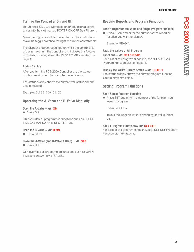
Turning the Controller On and OffTo turn the PCS 2000 Controller on or off, insert a screw driver into the slot marked POWER ON/OFF. See Figure 1.
Move the toggle switch to the left to turn the controller on. Move the toggle switch to the right to turn the controller off.
The plunger program does not run while the controller is off. When you turn the controller on, it closes the A-valve and starts counting down the CLOSE TIME (see step 1 on page 6).
Status Display
After you turn the PCS 2000 Controller on, the status display remains on. The controller never sleeps.
The status display shows the current well status and the time remaining.
Example: CLOSE 000:00:00
Operating the A-Valve and B-Valve Manually
Open the A-Valve = ☛ ONPress ON. �
ON overrides all programmed functions such as CLOSE TIME and MANDATORY SHUT-IN TIME.
Open the B-Valve = ☛ B ONPress B ON. �
Close the A-Valve (and B-Valve if Used) = ☛ OFFPress OFF. �
OFF overrides all programmed functions such as OPEN TIME and DELAY TIME (SALES).
Reading Reports and Program Functions
Read a Report or the Value of a Single Program FunctionPress READ and enter the number of the report or �function you want to display.
Example: READ 4.
Read the Values of All Program Functions = ☛ READ READFor a list of the program functions, see “READ READ Program Function List” on page 4.
Display the Well’s Current Status = ☛ READ 1The status display shows the current program function and the time remaining.
Setting Program Functions
Set a Single Program FunctionPress SET and enter the number of the function you �want to program.
Example: SET 5.
To exit the function without changing its value, press CE.
Set All Program Functions = ☛ SET SETFor a list of the program functions, see “SET SET Program Function List” on page 4.

4
USER GUIDEP
CS
200
0 CO
NTRO
LLER report and program FunCtion
reFerenCeThe tables in this section cross-reference the reports and program functions described in this User Guide.
Reports
Report READ Page
Software Version Report CE 5
Battery and Solar Panel Status Report 0 5
A-Valve and Plunger Counts History 4 5
B-Valve and Plunger Counts History B4 5
Plunger Travel Time History 6 5
A-Valve Total Open Time Report 7 5
B-Valve Total Open Time Report B7 5
Synchronized Time Status 8 5
Sensor Status 9 5
Clearing Report Values
Program Function SET Display Name Page
Clear A-Valve and Plunger Counts History
4 A PL=0092 V=0096 5
Clear B-Valve and Plunger Counts History
B4 B PL=0002 V=0002 5
Clear A-Valve Total Open Time Report
7 A TOTAL016:31:13 5
Clear B-Valve Total Open Time Report
B7 B TOTAL001:24:32 5
Program Functions
READ READ Program Function ListPress READ READ to display the current times programmed in all functions listed below.
SET SET Program Function ListPress SET SET to program all functions listed below.
Program Function
SET or READ
Display Name
Page
OPEN TIME ON OPEN 6
CLOSE TIME OFF CLOSE TIME 6
DELAY TIME (SALES)
FAST PLUNGER TIME and FAST COUNT
2 DELAY
FAST-TM
FAST COUNT
7
8
MANDATORY SHUT-IN TIME
3 MAND-SI 7
B OPEN TIME B ON B OPEN 6
B DELAY TIME B2 BDELAY 7
FALL TIME 5 FALL TM 7
Sensor Operation 9 SENSOR 6
Additional Program FunctionsTo program these functions, press SET parameter.To display their current values, press READ parameter.
Program Function
SET or READ Display Name
Page
Status of A-Valve when B-Valve Is Open
Note: READ B 0 is not available.
B 0 SET B: A ON-OFF 6
B-Valve Trip Counter B OFF TRIP COUNT 7
Synchronized Time Feature
8 SYNCROTM 6
USER GUIDE
5
PC
S 2000 CONTROLLER
Controller reports
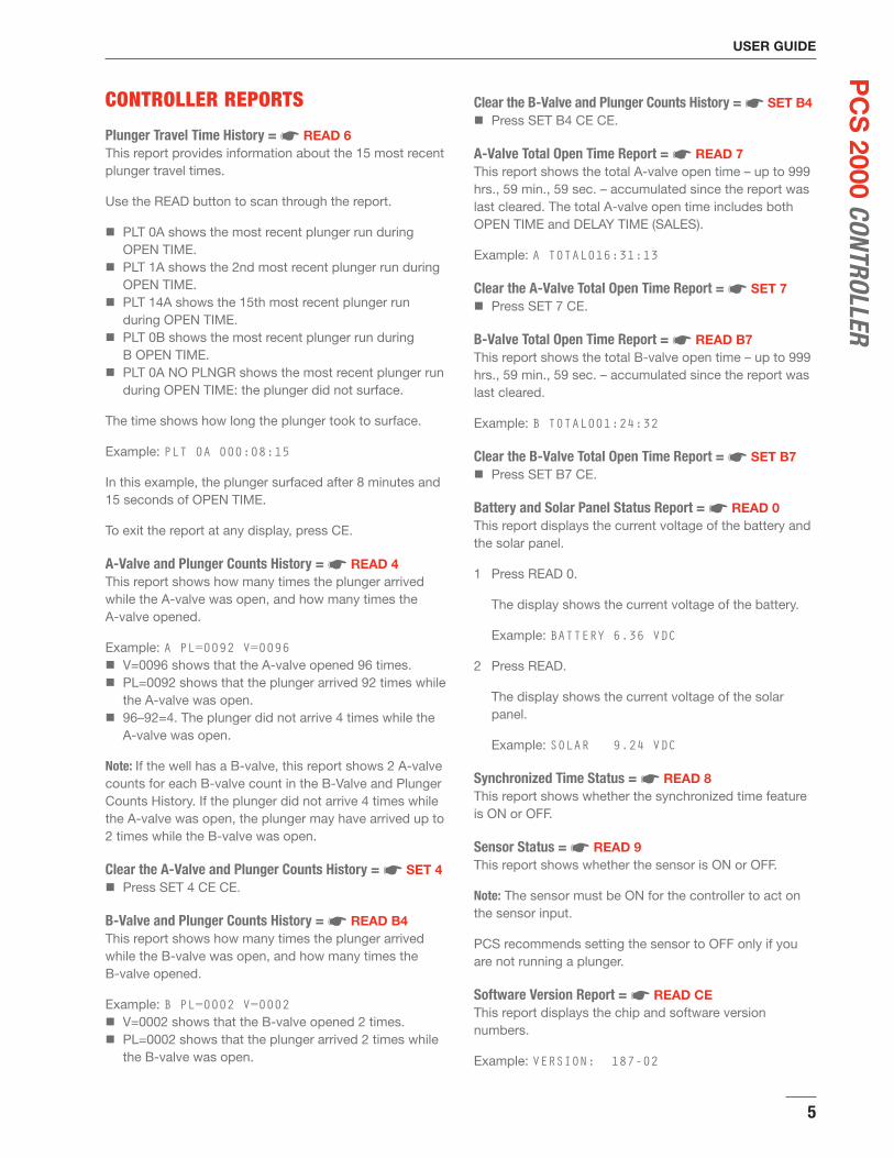
Plunger Travel Time History = ☛ READ 6This report provides information about the 15 most recent plunger travel times.
Use the READ button to scan through the report.
PLT 0A shows the most recent plunger run during �OPEN TIME.PLT 1A shows the 2nd most recent plunger run during �OPEN TIME.PLT 14A shows the 15th most recent plunger run �during OPEN TIME.PLT 0B shows the most recent plunger run during �B OPEN TIME.PLT 0A NO PLNGR shows the most recent plunger run �during OPEN TIME: the plunger did not surface.
The time shows how long the plunger took to surface.
Example: PLT 0A 000:08:15
In this example, the plunger surfaced after 8 minutes and 15 seconds of OPEN TIME.
To exit the report at any display, press CE.
A-Valve and Plunger Counts History = ☛ READ 4This report shows how many times the plunger arrived while the A-valve was open, and how many times the A-valve opened.
Example: A PL=0092 V=0096V=0096 shows that the A-valve opened 96 times. �PL=0092 shows that the plunger arrived 92 times while �the A-valve was open.96–92=4. The plunger did not arrive 4 times while the �A-valve was open.
Note: If the well has a B-valve, this report shows 2 A-valve counts for each B-valve count in the B-Valve and Plunger Counts History. If the plunger did not arrive 4 times while the A-valve was open, the plunger may have arrived up to 2 times while the B-valve was open.
Clear the A-Valve and Plunger Counts History = ☛ SET 4Press SET 4 CE CE. �
B-Valve and Plunger Counts History = ☛ READ B4This report shows how many times the plunger arrived while the B-valve was open, and how many times the B-valve opened.
Example: B PL=0002 V=0002V=0002 shows that the B-valve opened 2 times. �PL=0002 shows that the plunger arrived 2 times while �the B-valve was open.
Clear the B-Valve and Plunger Counts History = ☛ SET B4Press SET B4 CE CE. �
A-Valve Total Open Time Report = ☛ READ 7This report shows the total A-valve open time – up to 999 hrs., 59 min., 59 sec. – accumulated since the report was last cleared. The total A-valve open time includes both OPEN TIME and DELAY TIME (SALES).
Example: A TOTAL016:31:13
Clear the A-Valve Total Open Time Report = ☛ SET 7Press SET 7 CE. �
B-Valve Total Open Time Report = ☛ READ B7This report shows the total B-valve open time – up to 999 hrs., 59 min., 59 sec. – accumulated since the report was last cleared.
Example: B TOTAL001:24:32
Clear the B-Valve Total Open Time Report = ☛ SET B7Press SET B7 CE. �
Battery and Solar Panel Status Report = ☛ READ 0This report displays the current voltage of the battery and the solar panel.
Press READ 0.1
The display shows the current voltage of the battery.
Example: BATTERY 6.36 VDC
Press READ.2
The display shows the current voltage of the solar panel.
Example: SOLAR 9.24 VDC
Synchronized Time Status = ☛ READ 8This report shows whether the synchronized time feature is ON or OFF.
Sensor Status = ☛ READ 9This report shows whether the sensor is ON or OFF.
Note: The sensor must be ON for the controller to act on the sensor input.
PCS recommends setting the sensor to OFF only if you are not running a plunger.
Software Version Report = ☛ READ CEThis report displays the chip and software version numbers.
Example: VERSION: 187-02

6
USER GUIDEP
CS
200
0 CO
NTRO
LLER How plunger operation works
1 The controller closes the A-valve to shut in the well and counts down the CLOSE TIME (SET OFF). This gives the plunger time to fall to the bottom of the well.
Note: If connected to a pressure switch, the controller counts down both the CLOSE TIME and FALL TIME.
2 When the CLOSE TIME countdown reaches zero, the controller opens the A-valve.
Important! FALL TIME, if used, must be shorter than CLOSE TIME. For more information, see “FALL TIME” on page 7.
3 The controller counts down the OPEN TIME (SET ON).If the plunger arrives during the OPEN TIME �countdown, the controller goes to step 5.If the plunger does not arrive during the OPEN TIME �countdown, the controller goes to step 4.
4 The controller opens the optional B-valve and counts down the B OPEN TIME (SET B ON).
If the plunger arrives during the B OPEN TIME �countdown, the controller goes to step 5.If the plunger does not arrive during either OPEN �TIME or B OPEN TIME, the controller closes the A-valve and B-valve and counts down the MANDATORY SHUT-IN TIME (SET 3). When this countdown reaches zero, the controller opens the A-valve. The controller goes back to step 3.
Note: If the well has liquid trailing behind the plunger, you may want to set B DELAY TIME. See “B DELAY TIME” on page 7 for more information.
5 The controller counts down the DELAY TIME (SALES) (SET 2). When the DELAY TIME (SALES) countdown reaches zero, the controller goes back to step 1.
Creating a plunger programThe fastest way to program the controller is to press SET SET. See “SET SET Program Function List” on page 4.
Program Selection Functions
Sensor Operation = ☛ SET 9Set the sensor to ON.
If you set the sensor to OFF, the controller goes directly from OPEN TIME to CLOSE TIME. It does not go from OPEN TIME to DELAY TIME (SALES). The controller does count plunger arrivals for the Plunger Travel Time History.
Status of A-Valve when B-Valve Is Open = ☛ SET B 0The controller works on wells that require the A-valve to be either open or closed when the B-valve is open.
To keep A-valve open when B-valve is open, press ON. �To close A-valve when B-valve is open, press OFF. �
Synchronized Time Feature = ☛ SET 8If multiple wells share the same sales line and separator, the synchronized time feature allows you to program the controllers so that only 1 well is open at a time.
When the synchronized time feature is ON, the controller makes sure that each full plunger cycle takes the same amount of time. The controller adds any OPEN TIME remaining after the plunger has surfaced to the CLOSE TIME for that plunger cycle. If B OPEN TIME has been programmed, the controller also adds the B OPEN TIME to the CLOSE TIME for the plunger cycle.
Example:OPEN TIME is 30 minutes. �B OPEN TIME is 5 minutes. �CLOSE TIME is 2 hours. �The plunger surfaces after 15 minutes of OPEN TIME. �The controller adds the remaining 15 minutes of �OPEN TIME and the 5 minutes of B OPEN TIME to the CLOSE TIME, making it 2 hours and 20 minutes.
Program Control Functions
CLOSE TIME = ☛ SET OFFCLOSE TIME is when the well is shut-in and not flowing. It is also when the plunger falls, and the well builds pressure for the next cycle.
Important! You must have a CLOSE TIME unless a pressure switch is being used to open the well. Do not program 000:00:00 as the CLOSE TIME unless a pressure switch is being used.
OPEN TIME = ☛ SET ONOPEN TIME is when the well is first opened, and gas is flowing through the A-valve (motor valve). During OPEN TIME, the plunger starts to surface and the well sells its initial head gas.
B OPEN TIME = ☛ SET B ON OptionalB OPEN TIME is after the well has sold its initial head gas, but the plunger has not arrived. During B OPEN TIME, the plunger surfaces with the liquid load it is carrying. Typically, gas during B OPEN TIME is vented to the low pressure side of the separator or to a tank.
If you are not using a B-valve, set B OPEN TIME to 000:00:00.

USER GUIDE
7
PC
S 2000 CONTROLLER
DELAY TIME (SALES) = ☛ SET 2DELAY TIME (SALES) sells gas through the A-valve after the plunger has arrived.
Note: Status displays for FAST PLUNGER TIME and FAST COUNT follow DELAY TIME (SALES). See “Fast Plunger Time Safeguard” on page 8 for more information.
MANDATORY SHUT-IN TIME = ☛ SET 3 OptionalIf the A-valve and B-valve are opened, but a plunger does not surface, the well likely needs more time to rebuild pressure for the next plunger attempt.
Set the MANDATORY SHUT-IN TIME to at least twice the time required to build enough pressure to surface the plunger. For example, if a well usually takes 2 hours to build enough pressure to surface the plunger, set MANDATORY SHUT-IN TIME to 4 hours or more.
Note: MANDATORY SHUT-IN TIME must be greater than CLOSE TIME. If the plunger does not surface, MANDATORY SHUT-IN TIME replaces CLOSE TIME. MANDATORY SHUT-IN TIME is not in addition to CLOSE TIME.
If you are not using MANDATORY SHUT-IN TIME, set it to 000:00:00.
Features for Special Circumstances
FALL TIME = ☛ SET 5FALL TIME is used when a pressure switch is connected to the controller. FALL TIME guarantees a minimum shut-in time for the plunger to fall to the bottom of the well.
When the controller is used with a pressure switch, FALL TIME overrides both CLOSE TIME and input from a pressure switch. The controller will not open the A-valve before the FALL TIME countdown reaches zero. After the FALL TIME countdown reaches zero, the controller opens the A-valve as soon as it receives a pressure switch input. It opens the A-valve immediately if a pressure switch input has already been received. If no input is received, the controller opens the A-valve when the CLOSE TIME countdown reaches zero.
Important! If you program a FALL TIME, it should be shorter than CLOSE TIME because it has the highest priority – above both CLOSE TIME and input from a pressure switch. The controller will not open the A-valve before the FALL TIME countdown reaches zero.
When the controller is used with a pressure switch, program CLOSE TIME for the maximum time you want the well to be shut in. If the pressure switch does not meet its set point, the controller opens the well when both the FALL TIME and CLOSE TIME have counted down to zero. See CLOSE TIME on page 6 for more information.
Note: The PCS 2000 controller normally is not connected to a pressure switch.
If you are not using a pressure switch, program 000:00:00 for FALL TIME.
B DELAY TIME = ☛ SET B2B DELAY TIME is normally set to 000:00:00.
In the rare instance that liquid is trailing behind the plunger, you may want to set a few seconds of B DELAY TIME to let the liquid clear out of the dump valve on the separator.
When the B DELAY TIME is set, and when the plunger arrives during the B OPEN TIME countdown, the controller delays closing the B-valve by starting the B DELAY TIME countdown. When the countdown reaches zero, the controller closes the B-valve and starts the DELAY TIME (SALES) countdown.
B TRIP COUNT = ☛ SET B OFF
B TRIP COUNT specifies the number of open and close cycles the controller runs before it opens the B-valve.
Example: If you program a B TRIP COUNT of 5, the controller goes through 5 open and close cycles before it opens the B-valve.
Important! After you program the B TRIP COUNT, you must press B ON to activate the B-valve trip counter (and open the B-valve). The trip counter does not start automatically when the controller’s operating program opens the B-valve.
Note: You cannot exit B TRIP COUNT by pressing CE. You must specify a trip count. To exit the function without changing the value, enter the value shown on the display.
If you are not using B TRIP COUNT, set it to 00.

8
USER GUIDEP
CS
200
0 CO
NTRO
LLER Fast Plunger Time Safeguard
Important! Use the fast plunger time safeguard as an added safety precaution.
FAST PLUNGER TIME and FAST COUNT = ☛ SET 2The controller uses FAST PLUNGER TIME and FAST COUNT to shut in the well if the plunger runs too fast (over 1000 ft/min). After the controller shuts in the well, the status display shows TOO FAST SHUTIN. To restart the plunger operation program, press ON or OFF.
ON opens the A-valve and counts down the OPEN TIME. See step 2 on page 6 (under “How Plunger Operation Works”).
OFF leaves the A-valve closed and counts down the CLOSE TIME. See step 1 on page 6 (under “How Plunger Operation Works”).
To set FAST PLUNGER TIME and FAST COUNT, press 1 SET 2.
The status display shows the DELAY TIME (SALES).
Press CE.2
The status display shows the FAST PLUNGER TIME in hours, minutes, and seconds.
Set the FAST PLUNGER TIME.3
Example: For a 7000 foot well, a good plunger arrival time is 7-14 minutes. Continual high-speed plunger runs faster than 3000 ft/min can cause the PCS lubricator to fail. A high-speed plunger run up a 7000 foot well takes 2 minutes and 20 seconds. Set the FAST PLUNGER TIME to 000:04:00.
Tip! The recommended plunger travel speed is between 500 and 1000 feet per minute. Use these values to set the FAST PLUNGER TIME.
After you set the FAST PLUNGER TIME, the status display shows the FAST COUNT.
Set the FAST COUNT.4
In the example above for a 7000 foot well, set the FAST COUNT to 2. If the plunger has 2 consecutive travel times faster than 4 minutes, the controller shuts in the well.
The maximum FAST COUNT is 8.
trouBlesHootingIf you have a problem with the controller, try these troubleshooting tips. If they don’t solve the problem, call your PCS sales and service representative.
Controller Display Problems
Controller won’t turn on or controller’s display is blankThe controller never sleeps. The display should never be blank while the controller is on.
With a screwdriver, move the power switch to off (see 1 page 3).Wait a few seconds and then move the power switch 2 back to on.If the display remains blank, go to Test 1.
Test 1: Check fuse.With a screwdriver, move the power switch to off.1 Remove the controller’s faceplate.2 Remove the fuse from its yellow casing.3
If the fuse is defective, replace it with a 5 amp, 250 �volt fuse. The controller’s box contains 1 extra fuse.When you are done, replace the controller’s faceplate and move the power switch to on.If the fuse is OK, go to Test 2. �
Test 2: Check battery and wire connection.The battery life is approximately 1 to 3 years.The controller has a safety feature. If the battery voltage is low, the controller closes the motor valve and shuts in.
Check the battery voltage with a volt meter.1 Replace the battery if it is below 6 volts.Check the battery wires for loose connections.2 Replace the controller’s faceplate.3 With a screwdriver, move the power switch to on.4
If the display is still blank, call your PCS sales and �service representative.
If the controller’s display is now working and if you 5 replaced the battery, check the manufacture date on the battery. If the battery is less than 3 years old, check the solar panel. Go to Test 3.
Test 3: Check solar panel.Disconnect the solar panel from the terminals. Use a 1 volt meter to obtain the voltage and amperage.
For a 6 volt - 3.3 watt solar panel (9" wide by 7.75" �high), a good reading in full sun exposure is 10.7 volts and 350-430 mA.For a 6 volt - 1.3 watt solar panel (4.5" wide by �5.75" high), a good reading in full sun exposure is 10.7 volts and 130-190 mA.
If the solar panel is defective, change it.2

USER GUIDE
9
PC
S 2000 CONTROLLER
Check the solar panel installation.3 The solar panel should face south. �The tilt of the solar panel should be the latitude �of the location plus 15 degrees. Example: if the latitude is 45 degrees, tilt the solar panel 60 degrees with respect to the horizon.The element should be free from dirt, oil, and so on. �Check for cracks in the solar panel. �Check whether the solar panel is shaded during any �part of the day. If it is, re-position it to receive the most sunlight each day.
Check the solar panel wire connection.4 Make sure the power switch is on. The controller’s 5 display should be on.If the solar panel tests good, but the batteries are not 6 lasting as long as they should, call your PCS sales and service representative.
Controller’s display is scrambledStatic electricity may have made the controller lose its place in the program cycle.
Reset the controller: With a screwdriver, move the 1 power switch to off (see page 3). Wait a few seconds and then move the power switch back to on.If the display is still scrambled after this test, call your 2 PCS sales and service representative.
Program Cycle Problems
Controller won’t run program cycle or won’t open motor valve
Check the status display.1 If it shows TOO FAST SHUT-IN, the plunger’s travel �time was too fast. Go to step 2.If it does not show TOO FAST SHUT-IN, go to �Test 1.
2 Inspect the plunger for damage. If the plunger is not damaged, press ON or OFF to restart the plunger operation program.
Test 1: Check battery and wire connection.The battery life is approximately 1 to 3 years.The controller has a safety feature. If the battery voltage is low, the controller closes the motor valve and shuts in.
Press READ 0 and check the battery’s voltage.1 Replace the battery if it is below 6 volts.With a screwdriver, move the power switch to off (see 2 page 3).Remove the controller’s faceplate.3 Check the battery wires for loose connections.4 Make sure the fuse is good.5 Replace the controller’s faceplate.6 With a screwdriver, move the power switch to on.7
Press ON and OFF a few times to make sure the 8 solenoid is shifting.
If the controller is now operating properly and if you �replaced the battery, check the manufacture date on the battery. If the battery is less than 3 years old, check the solar panel. Go to Test 2.If the controller still won’t run the program cycle or �open the motor valve, go to Test 3.
Test 2: Check solar panel.Disconnect the solar panel from the terminals. Use a 1 volt meter to obtain the voltage and amperage.
For a 6 volt - 3.3 watt solar panel (9" wide by 7.75" �high), a good reading in full sun exposure is 10.7 volts and 350-430 mA.For a 6 volt - 1.3 watt solar panel (4.5" wide by �5.75" high), a good reading in full sun exposure is 10.7 volts and 130-190 mA.
If the solar panel is defective, change it.2 Check the solar panel installation.3
The solar panel should face south. �The tilt of the solar panel should be the latitude �of the location plus 15 degrees. Example: if the latitude is 45 degrees, tilt the solar panel 60 degrees with respect to the horizon.The element should be free from dirt, oil, and so on. �Check for cracks in the solar panel. �Check whether the solar panel is shaded during any �part of the day. If it is, re-position it to receive the most sunlight each day.
Check the solar panel wire connection.4 Make sure the power switch is on. The controller’s 5 display should be on.If the solar panel tests good, but the batteries are not 6 lasting as long as they should, call your PCS sales and service representative.
Test 3: Check solenoid (shift valve).Press ON.1 If the solenoid won’t open, clean the supply hoses and 2 puck inside the solenoid valve.Retest.3 If they are good, replace the puck or the entire 4 solenoid.
Test 4: Check gas supply pressure, filter, and regulator(s).Check the gas supply pressure to the motor valve.1 The recommended supply pressure is 25-35 psi. If the pressure is too low or too high, it will not open the motor valve.Check the filter and regulator(s) for debris and ice.2 If the controller is still not working properly, call your 3 PCS sales and service representative.

10
USER GUIDEP
CS
200
0 CO
NTRO
LLER After CLOSE TIME has counted down to zero, controller
goes directly to DELAY TIME (SALES)Press READ 6 to check the Plunger Travel Time �History. If the display shows a few seconds of plunger travel time, such as PLT 0A 000:00:03, the controller went through the opening and closing part of the program even though the plunger did not arrive.
Test 1: Check the sensor wire connections.If a wire was spliced in because of the distance 1 between the controller and the sensor, check the connection where the wire was spliced. The wire may be corroded and causing a short.If the sensor wire connections are good, go to Test 2.2
Test 2: Check controller by disconnecting the sensor.Disconnect the sensor from the SENSOR IN and 1 SENSOR - terminals on the inside of the controller’s faceplate.Press ON. The controller should count down the OPEN 2 TIME.
If the controller goes from OPEN TIME to DELAY �TIME (SALES), the controller’s circuit board is not working properly. Call your PCS sales and service representative.If the controller does not go to DELAY TIME �(SALES), continue with the next step.
Use a wire to short the SENSOR IN and SENSOR - 3 terminals. The controller is OK if it goes to DELAY TIME (SALES).Reconnect the sensor to the terminals. Make sure the 4 wires are connected correctly.
Test 3: Check plunger.Check whether the plunger is stuck in the lubricator.1 If the plunger is not stuck in the lubricator, go to Test 4.2
Test 4: Check the sensor.Remove the sensor from the wellhead.1 Press ON.2
If the controller counts down the OPEN TIME, go to �step 3.If the controller goes straight into DELAY TIME �(SALES), there is a short. Either the wire going to the controller is bad, or the sensor must be replaced. Go to step 5.
3 Hold the sensor in your hand, and move a steel wrench through the sensor band.
If the controller goes to DELAY TIME (SALES), the �problem may be a wellhead electrical current.Go to � step 4.
4 Possible causes of a wellhead electrical problem:The sensor or sensor wire may be defective, or �The well may need the newest version of PCS’ �2-coil sensor. This sensor is available in 2-wire or 3-wire connections.
5 Call your PCS sales and service representative.
Plunger has surfaced, but OPEN TIME does not go to DELAY TIME (SALES)
Make sure sensor is turned on: Press READ 9. The �controller’s display should show SENSOR: ON.
If the display shows SENSOR: ON, go to Test 1. �If the display shows SENSOR: OFF, press SET 9 �and then press ON. Go to Test 2, step 2.
Test 1: Check controller by disconnecting the sensor.Disconnect the sensor from the SENSOR IN and 1 SENSOR - terminals on the inside of the controller’s faceplate.Press ON. The controller should count down the OPEN 2 TIME.
If the controller goes from OPEN TIME to DELAY �TIME (SALES), the controller’s circuit board is not working properly. Call your PCS sales and service representative.If the controller does not go to DELAY TIME �(SALES), continue with the next step.
Use a wire to short the SENSOR IN and SENSOR - 3 terminals. The controller is OK if it goes to DELAY TIME (SALES).Reconnect the sensor to the terminals. Make sure the 4 wires are connected correctly.
Test 2: Check sensor.Press ON.1
2 Run a steel wrench along the back of the sensor.If the controller goes to DELAY TIME (SALES), the �sensor is OK.If the controller does not go to DELAY TIME �(SALES), call your PCS sales and service representative.
Test 3: Check sensor alignment.Realign the sensor by 90 degrees.1 Example: If the sensor is aligned on the north or south side, realign it on the east or west side.If realigning the sensor does not solve the problem, call 2 your PCS sales and service representative.

USER GUIDE
11
PC
S 2000 CONTROLLER
Plunger has surfaced, but Plunger Travel Time History (READ 6) shows NO PLNGR instead of a travel time
Make sure sensor is turned on: Press READ 9. The �controller’s display should show SENSOR: ON.
If the display shows SENSOR: ON, go to Test 1. �If the display shows SENSOR: OFF, press SET 9 �and then press ON. Go to Test 2, step 2.
Test 1: Check controller by disconnecting the sensor.Disconnect the sensor from the SENSOR IN and 1 SENSOR - terminals on the inside of the controller’s faceplate.Press ON. The controller should count down the OPEN 2 TIME.
If the controller goes from OPEN TIME to DELAY �TIME (SALES), the controller’s circuit board is not working properly. Call your PCS sales and service representative.If the controller does not go to DELAY TIME �(SALES), continue with the next step.
Use a wire to short the SENSOR IN and SENSOR - 3 terminals. The controller is OK if it goes to DELAY TIME (SALES).Reconnect the sensor to the terminals. Make sure the 4 wires are connected correctly.
Test 2: Check sensor.Press ON.1
2 Run a steel wrench along the back of the sensor.If the controller goes to DELAY TIME (SALES), the �sensor is OK.If the controller does not go to DELAY TIME �(SALES), call your PCS sales and service representative.
Test 3: Check sensor alignment.Realign the sensor by 90 degrees.1 Example: If the sensor is aligned on the north or south side, realign it on the east or west side.If realigning the sensor does not solve the problem, call 2 your PCS sales and service representative.
Solenoid (Shift Valve) Problems
Solenoid (shift valve) does not operate at any time or does not operate at nightIf the solenoid does not operate at night, the solar panel may be powering the controller during the day.
Test 1: Check battery and wire connection.The battery life is approximately 1 to 3 years.The controller has a safety feature. If the battery voltage is low, the controller closes the motor valve and shuts in.
Press READ 0 and check the battery’s voltage.1 Replace the battery if it is below 6 volts.
With a screwdriver, move the power switch to off (see 2 page 3).Remove the controller’s faceplate.3 Check the battery wires for loose connections.4 Make sure the fuse is good.5 Replace the controller’s faceplate.6 With a screwdriver, move the power switch to on.7 Press ON and OFF a few times to make sure the 8 solenoid is shifting.
If the solenoid is now operating properly and if you �replaced the battery, check the manufacture date on the battery. If the battery is less than 3 years old, check the solar panel. Go to Test 2.If the solenoid still does not operate, go to Test 3. �
Test 2: Check solar panel.Disconnect the solar panel from the terminals. Use a 1 volt meter to obtain the voltage and amperage.
For a 6 volt - 3.3 watt solar panel (9" wide by 7.75" �high), a good reading in full sun exposure is 10.7 volts and 350-430 mA.For a 6 volt - 1.3 watt solar panel (4.5" wide by �5.75" high), a good reading in full sun exposure is 10.7 volts and 130-190 mA.
If the solar panel is defective, change it.2 Check the solar panel installation.3
The solar panel should face south. �The tilt of the solar panel should be the latitude �of the location plus 15 degrees. Example: if the latitude is 45 degrees, tilt the solar panel 60 degrees with respect to the horizon.The element should be free from dirt, oil, and so on. �Check for cracks in the solar panel. �Check whether the solar panel is shaded during any �part of the day. If it is, re-position it to receive the most sunlight each day.
Check the solar panel wire connection.4 Make sure the power switch is on. The controller’s 5 display should be on.If the solar panel tests good, but the batteries are not 6 lasting as long as they should, call your PCS sales and service representative.
Test 3: Check solenoid (shift valve).Press ON.1 If the solenoid won’t open, clean the supply hoses and 2 puck inside the solenoid valve.Retest.3 If they are good, replace the puck or the entire solenoid.4
preventive maintenanCe
BatteryAlways replace the controller’s battery when it is 3 years old.

3771 Eureka Way Frederick, CO 80516 1.800.619.2241
Warranty: Production Control Services, Inc. warrants all PCS manufactured equipment to be free of defects in material and workmanship for ONE YEAR from date of purchase by original buyer only. Warranty is completely void if abuse, neglect, misuse or misapplication is the cause of the malfunction. Determination of abuse or damage to be made solely by PCS.
PCS 2000™ is a trademark of Production Control Services, Inc.
Copyright ©2008 Production Control Services, Inc. All rights reserved. 10/2/08
You can get more information about the PCS products at: pcslift.com
PC
S 2
000
CONT
ROLL
ERUSER GUIDE