SIMATIC Process Control System PCS 7 PC Configuration ...
136
s Preface, Contents PC Components of a PCS 7 Plant 1 Hardware for PC Stations 2 Installing the PC Stations 3 Appendices Appendix A - Using the Software Packages A Appendix B - Licensing the Software Package B Appendix C - Approved Configurations on a PC Station C Index SIMATIC Process Control System PCS 7 PC Configuration and Authorization Manual Edition 07/2005 A5E00353686-02
-
Upload
khangminh22 -
Category
Documents
-
view
1 -
download
0
Transcript of SIMATIC Process Control System PCS 7 PC Configuration ...

s
Preface, Contents PC Components of a PCS 7 Plant 1 Hardware for PC Stations 2 Installing the PC Stations 3 Appendices Appendix A - Using the Software Packages AAppendix B - Licensing the Software Package BAppendix C - Approved Configurations on a PC Station CIndex
SIMATIC
Process Control System PCS 7 PC Configuration and Authorization Manual
Edition 07/2005 A5E00353686-02

Copyright Siemens AG 2005 All rights reserved The reproduction, transmission or use of this document or its contents is not permitted without express written authority. Offenders will be liable for damages. All rights, including rights created by patent grant or registration of a utility model or design, are reserved. Siemens AG Bereich Automation and Drives Geschaeftsgebiet Industrial Automation Systems Postfach 4848, D- 90327 Nuernberg
Disclaimer of Liability We have checked the contents of this manual for agreement withthe hardware and software described. Since deviations cannot beprecluded entirely, we cannot guarantee full agreement. However,the data in this manual are reviewed regularly and any necessarycorrections included in subsequent editions. Suggestions forimprovement are welcomed. Siemens AG 2005 Technical data subject to change.
Siemens Aktiengesellschaft A5E00353686-02
Safety Guidelines
This manual contains notices intended to ensure personal safety, as well as to protect the products and connected equipment against damage. These notices are highlighted by the symbols shown below and graded according to severity by the following texts:
! Danger indicates that death, severe personal injury or substantial property damage will result if proper precautions are not taken.
! Warning indicates that death, severe personal injury or substantial property damage can result if proper precautions are not taken.
! Caution indicates that minor personal injury can result if proper precautions are not taken.
Caution
indicates that property damage can result if proper precautions are not taken.
Notice draws your attention to particularly important information on the product, handling the product, or to a particular part of the documentation.
Qualified Personnel
Only qualified personnel should be allowed to install and work on this equipment. Qualified persons are defined as persons who are authorized to commission, to ground and to tag circuits, equipment, and systems in accordance with established safety practices and standards.
Correct Usage
Note the following:
! Warning This device and its components may only be used for the applications described in the catalog or the technical description, and only in connection with devices or components from other manufacturers which have been approved or recommended by Siemens. This product can only function correctly and safely if it is transported, stored, set up, and installed correctly, and operated and maintained as recommended.
Trademarks
SIMATIC®, SIMATIC HMI® and SIMATIC NET® are registered trademarks of SIEMENS AG.
Third parties using for their own purposes any other names in this document which refer to trademarks might infringe upon the rights of the trademark owners.

Preface
Purpose of the Documentation This documentation provides you with an overview of the PC components used in PCS 7. It provides you with information about:
• The PC components that can be used in PCS 7 applications
• The software and hardware you require for specific PC components
• The authorizations and licenses you require for individual products
• The possible PC configurations for an application
• How to design and configure your PC network
The documentation is intended for persons involved in configuration, commissioning, and service.
Basic Knowledge Required To understand this documentation, you should be familiar with automation engineering and process control engineering. You should also have experience of using PCs and similar (for example programming devices) and the Windows operating system used. Before installing PC components for PCS 7, make sure that you read the readme file about the latest version of PCS 7.
Validity The documentation is valid for the software package "Process Control System PCS 7 Toolset V6.1".
Licenses and Authorizations As of PCS 7 V6.0 SP3, the Automation License Manager is supplied for transferring authorizations. This program replaces the previously used, AuthorsW. All previous functions for transferring authorizations are possible with the Automation License Manager.
The technical implementations of a license were previously the authorizations that will gradually be replaced by license keys. In the manual, the technical implementations of a license will still be called authorizations until the changeover is complete.
Process Control System PCS 7 - PC Configuration and Authorization A5E00353686-02 iii
Preface
Further Support If you have any technical questions, please get in touch with your Siemens representative or agent responsible.
You will find your contact person at:
http://www.siemens.com/automation/partner
You will find a guide to the technical documentation offered for the individual SIMATIC Products and Systems here at:
http://www.siemens.com/simatic-tech-doku-portal
The online catalog and order system is found under:
http://mall.automation.siemens.com/
Training Centers Siemens offers a number of training courses to familiarize you with the Process Control System PCS 7. Please contact your regional training center or our central training center in D 90327 Nuremberg, Germany for details: Telephone: +49 (911) 895-3200. Internet: http://www.sitrain.com
Technical Support You can reach the Technical Support for all A&D products
• Via the Web formula for the Support Request http://www.siemens.com/automation/support-request
• Phone: + 49 180 5050 222
• Fax: + 49 180 5050 223
Additional information about our Technical Support can be found on the Internet pages http://www.siemens.com/automation/service
Service & Support on the Internet In addition to our documentation, we offer our Know-how online on the internet at: http://www.siemens.com/automation/service&support
where you will find the following:
• The newsletter, which constantly provides you with up-to-date information on your products.
• The right documents via our Search function in Service & Support.
• A forum, where users and experts from all over the world exchange their experiences.
• Your local representative for Automation & Drives.
• Information on field service, repairs, spare parts and more under "Services".
Process Control System PCS 7 - PC Configuration and Authorization iv A5E00353686-02

Contents
1 PC Components of a PCS 7 Plant 1-1 1.1 Base Configuration of the PCS 7 Plant ............................................................ 1-1 1.2 Fault-tolerant (Redundant) Configurations ....................................................... 1-4 1.3 Possible Work Methods on Engineering Stations ............................................ 1-6 1.4 Differences Between Multiple Station Systems and Single Station Systems... 1-7 1.5 Solutions for Engineering Stations ................................................................... 1-9 1.5.1 Using Several Engineering Stations for PCS 7 Project Engineering................1-9 1.5.2 Using Single PCs for PCS 7 Project Engineering ..........................................1-10 1.5.3 Combination Engineering Station and Operator Station on a Single PC .......1-11 1.5.4 Process Control System SIMATIC PCS 7 BOX .............................................1-12 1.6 Solutions with Multiple Station Systems......................................................... 1-14 1.6.1 Operator Station - Multiple Station System ....................................................1-14 1.6.2 BATCH Station - Multiple Station System ......................................................1-16 1.6.3 Route Control Station Multiple Station Systems.............................................1-17 1.6.4 Maintenance Station - Multiple Station System..............................................1-18 1.6.5 Long-term Archiving with the Central Archive Server.....................................1-20 1.6.6 Access to the PCS 7 OS over Web Client......................................................1-21 1.7 Solutions with Single Station Systems ........................................................... 1-22 1.7.1 OS Single Station ...........................................................................................1-22 1.7.2 BATCH Single Station ....................................................................................1-23 1.7.3 Route Control Single Station ..........................................................................1-24 1.7.4 SIMATIC PCS 7 BOX Station.........................................................................1-24 1.8 Connecting the PC Stations ........................................................................... 1-25 1.8.1 Bus Connection between AS, OS, BATCH, RCS and ES..............................1-25 1.8.2 Connection to Terminal/Plant Bus ..................................................................1-26 1.8.3 Time Synchronization .....................................................................................1-27
2 Hardware for PC Stations 2-1 2.1 Preconfigured PC Systems for PCS 7 (Bundles) ............................................. 2-3 2.2 Components for Connecting to the Terminal/Plant Bus ................................... 2-4 2.3 Other Optional Hardware Components ............................................................ 2-5 2.4 Configuring and Ordering ................................................................................. 2-6
3 Installing the PC Stations 3-1 3.1 Overview of the Installation Procedure............................................................. 3-1 3.2 Hard Disk Partitioning....................................................................................... 3-2 3.3 Installing the Operating System........................................................................ 3-3 3.3.1 Notes on Installing the Operating System ........................................................3-3 3.3.2 How to install Windows XP and Windows Server 2003 ...................................3-5 3.3.3 How to Install Windows 2000 (Professional and Server) .................................3-7 3.3.4 How to Install Service Packs for the Operating System...................................3-9 3.3.5 How to Make Additional System Settings.......................................................3-10 3.3.6 How to Install Internet Explorer ......................................................................3-12 3.3.7 How to Install the Message Queuing Service.................................................3-13 3.3.8 How to Install the Microsoft SQL Server.........................................................3-17 3.3.9 Installing Additional Components ...................................................................3-18 3.3.10 How to Set the Language for a User (MUI) ....................................................3-19 3.3.11 How to Configure the Server Role for the Central Archive Server .................3-20
Process Control System PCS 7 - PC Configuration and Authorization A5E00353686-02 v

Contents
3.3.12 How to Configure Users and User Groups.....................................................3-21 3.3.13 Creating a Backup ..........................................................................................3-22 3.3.14 Setting Color Schemes and Font Sizes..........................................................3-23 3.4 Installing the PCS 7 Software......................................................................... 3-24 3.4.1 Notes on Installing PCS 7...............................................................................3-24 3.4.2 How to Install from the Network......................................................................3-26 3.4.3 How to Install the PCS 7 Software .................................................................3-26 3.4.4 How to Install the Central Archive Server (StoragePlus)................................3-29 3.4.5 Activating Redundancy...................................................................................3-31 3.4.6 Reinstallation/Updating...................................................................................3-32 3.4.7 Removing PCS 7 ............................................................................................3-32 3.5 Installing the Drivers for PCS 7 ...................................................................... 3-33 3.5.1 Drivers for Communication Modules ..............................................................3-33 3.5.1.1 How to Install Drivers for Communication Modules .......................................3-34 3.5.1.2 How to Configure Standard Communication Modules ...................................3-35 3.5.1.3 How to Disable the Power Saving Options of Network Cards .......................3-36 3.5.1.4 How to Activate Redundancy for Redundant OS/BATCH Servers ................3-37 3.5.1.5 How to Install the Driver for the Redundant Terminal Bus.............................3-38 3.5.1.6 How to Prepare an MS Server with CP 1613 for Diagnostics........................3-41 3.5.2 Additional Devices and Drivers for PCS 7 ......................................................3-43 3.5.2.1 How to Activate a Multi-VGA Graphics Card..................................................3-43 3.5.2.2 How to Activate a Sound Card .......................................................................3-45 3.5.2.3 How to Activate a DCF77 Module ..................................................................3-46 3.6 Licensing and Authorization ........................................................................... 3-47 3.6.1 Licensing and Authorization of the PCS 7 Software.......................................3-47 3.6.2 How to Transfer License Keys........................................................................3-49 3.6.3 Selecting the Correct License Keys/Authorizations........................................3-51 3.6.4 Determining the Process Objects for the Engineering Station .......................3-53 3.6.5 Determining the Process Objects for the Operator Station ............................3-54 3.6.6 Determining the Process Objects for the Maintenance Station......................3-56 3.6.7 Determining the Process Objects for the BATCH Station ..............................3-57 3.6.8 Determining the Routes for the Route Control Station ...................................3-58 3.6.9 Notes on SIMATIC PCS 7 BOX......................................................................3-59 3.7 Overview - Preparing PC Stations.................................................................. 3-61 3.7.1 Preparing PC Stations - An Overview ............................................................3-61 3.7.2 How to Configure the PC Station in the Configuration Console.....................3-61 3.7.3 How to Select the Communication Module in Simatic Shell...........................3-63 3.7.4 How to Make the Settings for Standard Network Adapters ............................3-64 3.7.5 Downloading the network configuration to the PC stations ............................3-64 3.8 Notes on Add-ons and Utilities ....................................................................... 3-65 3.8.1 Add-ons and Utilities.......................................................................................3-65 3.8.2 Programs for Data Communication ................................................................3-65 3.8.3 Virus Scanners ...............................................................................................3-66 3.8.4 Firewall............................................................................................................3-67 3.8.5 Screen Savers ................................................................................................3-67 3.8.6 Using Defragmenters......................................................................................3-67
Process Control System PCS 7 - PC Configuration and Authorization vi A5E00353686-02

Contents
A Appendix A - Using the Software Packages A-1 A.1 Software Package for Basic Engineering .........................................................A-1 A.2 Software Packages for Operator Stations ........................................................A-2 A.3 Software Packages for SIMATIC BATCH.........................................................A-3 A.4 Optional Software Packages ............................................................................A-4
B Appendix B - Licensing the Software Package B-1 B.1 Software Packages and Required Authorizations ............................................B-1
C Appendix C - Approved Configurations on a PC Station C-1 C.1 Approved Configurations ..................................................................................C-1
Index Index-1
Process Control System PCS 7 - PC Configuration and Authorization A5E00353686-02 vii

Contents
Process Control System PCS 7 - PC Configuration and Authorization viii A5E00353686-02

1 PC Components of a PCS 7 Plant
1.1 Base Configuration of the PCS 7 Plant
PC Components for ES/OS/BATCH/Route Control /IT PC components are used for engineering stations (ES), operator stations (OS), BATCH stations (BATCH) , Route Control Stations (RCS) and for connecting SIMATIC PCS 7 to the IT world. These stations are collectively referred to as "PC stations" in the context of PCS 7.
The following illustration shows the PC stations in a PCS 7 plant.
21 3 4 5
6
7 8
Process Control System PCS 7 - PC Configuration and Authorization A5E00353686-02 1-1

PC Components of a PCS 7 Plant
Legend to illustration
Station No. in illustration
Function
Engineering Station
1 The central engineering for all PCS 7 system components is performed on the engineering station: operator stations, BATCH stations, route control stations, automation systems, central and distributed I/Os. The configuration data are uploaded to the PCS 7 system components when the engineering is completed. Changes can only be made on the engineering station. This is followed by a new upload. Engineering stations are PCs on which the PCS 7 Engineering software for configuration of PCS 7 projects is installed.
Operator Station 2 Operating and monitoring of your PCS 7 plant in process mode are performed on the operator station. The operator station is connected to the plant bus to enable the required data communication. Operator stations are PCs on which the PCS 7 OS software is installed.
Maintenance Station
3 The states of plant components can be easily recognized on the maintenance station. Maintenance stations are PCs on which the PCS 7 OS software is installed and specially configured for diagnostics.
BATCH Station 4 Operating and monitoring of discontinuous processes (batch processes) in process mode are performed on the BATCH station. A connection to an operator station is required for data communication with the automation system. The BATCH station is connected to the terminal bus for this purpose. BATCH stations are PCs on which the SIMATIC BATCH software is installed.
Route Control Station
5 The route control station (RCS) is used to automate the transport of material and products in a PCS 7 plant. The route control station is connected to the plant bus to provide the required data communication. A connection to an operator station is required to display messages. Route control stations are PCs on which the SIMATIC Route Control software is installed.
Bus (Terminal Bus and Plant Bus)
6 The communication between and among the PCS 7 components AS, OS, BATCH, RCS and ES is carried out through a bus system (Industrial Ethernet). The tasks that these busses perform in PCS 7 plants are generally assigned as follows: • The terminal bus is used for communication between the following
components: - Operation and monitoring systems (OS, BATCH, RCS) - Engineering station - Components on a higher level (such as MES, office networks)
and • The plant bus is used for communication between:
- The servers (OS) and automation systems - The automation systems (SIMATIC connections)
Process Control System PCS 7 - PC Configuration and Authorization 1-2 A5E00353686-02

PC Components of a PCS 7 Plant
Station No. in illustration
Function
Automation SYSTEM
7 The automation system • registers and processes process variables from the connected
central and distributed I/O and outputs control information and setpoints to the process
• supplies the operator station with the data for visualization • Registers actions on the operator station and forwards them to the
process SIMATIC PCS 7 BOX
8 Full process control system for small plants based on the PCS 7 process control system
Process Control System PCS 7 - PC Configuration and Authorization A5E00353686-02 1-3

PC Components of a PCS 7 Plant
1.2 Fault-tolerant (Redundant) Configurations
Introduction The use of fault-tolerant components in a process control system can minimize the risk of production loss. A redundant design guarantees fault tolerance in a control system. This means that all the components involved in the process are redundantly available, permanently in operation and simultaneously take part in the execution of the control task. When a fault occurs or one of the control system components fails, the correctly operating redundant component takes over the continuing control task. The goal is to increase the fault tolerance or failure safety of the process control system.
Redundancy for PC Stations in a PCS 7 Plant You can use PCS 7 redundant components to guarantee high availability of PC stations.
Note the following properties for servers in this regard:
Properties Description
Reaction to server failure
In a project with a redundant server pair, the advantage is that if one of the servers fails, the process can continue to be operated and monitored using the redundant server without any interruption.
Number of Servers Max. 12 servers (pairs) in a PCS 7 plant Reaction in respect to a client
A redundant server pair reacts like one server from the perspective of the client.
Configuration All configuration data needs to be defined for one server only. The configuration data is then subsequently downloaded to both redundant servers.
Note the following properties for network components:
Properties Description
Switchover when a ring fails
The following are used as redundant network adapters: Server Adapter: Pro/1000MT and Desktop Adapter: Pro/1000GT (see the section "How to Install the Driver for the Redundant Terminal Bus").
Reaction when cables, ESM/OSM, network adapters of the PC fail
Automatic switchover to the redundant ring
Configuration ProSet® from Intel is used to configure the network properties.
Recommendation You should always use redundant server pairs when the availability of the respective application is critical in your PCS 7 plant.
Process Control System PCS 7 - PC Configuration and Authorization 1-4 A5E00353686-02

PC Components of a PCS 7 Plant
Further Information • Information about client/server architecture is available in the section,
"Differences between multiple station systems and single station systems".
• For more information about implementing redundancy for operator stations, refer to the function manual, Process Control System PCS 7; Fault-Tolerant Process Control Systems.
• For more information about configuring and implementing redundancy for route control stations, refer to the manual, Process Control System PCS 7; SIMATIC Route Control.
Process Control System PCS 7 - PC Configuration and Authorization A5E00353686-02 1-5

PC Components of a PCS 7 Plant
1.3 Possible Work Methods on Engineering Stations
You can use a variety of work methods on the engineering stations in a PCS 7 plant. For example, several PCs can be used for the PCS 7 plant engineering if the use of one PC is insufficient for a specific plant. The work method using several engineering PCs differs only in a few procedural steps from the work method using a single engineering station.
Properties Work Methods with Several
Engineering Stations Work Methods with One Engineering Station
Area of application
• Medium-sized and small plants • Configuration phases • Spatially separated configuration of
engineering stations
• Small plants • Local operator stations • Training systems
Monitors 1 or 2 recommended (max. 4 monitors per engineering workplace) Combination / Work method
• Using Several Engineering Stations for PCS 7 Project Engineering
• Using One Engineering Stations for PCS 7 Project Engineering
• Combination Engineering Station and Operator Station on a Single PC
• Working with SIMATIC PCS 7 BOX – an Industrial PC with Integrated AS/ES/OS.
Process Control System PCS 7 - PC Configuration and Authorization 1-6 A5E00353686-02

PC Components of a PCS 7 Plant
1.4 Differences Between Multiple Station Systems and Single Station Systems
Each PCS 7 application for process mode (OS, BATCH, RCS) can be configured as a single station system or as a multiple station system with client/server architecture.
Definition of Multiple Station System A multiple station system is a matching system of PCs in which the functionality of a PCS 7 application with a client/server architecture is distributed over several PCs (for example, OS clients, OS servers). The "PCS 7 Toolset" DVD provides the appropriate client or server software. When configuring a multiple station system, a terminal bus (separate from the plant bus) is recommended for data communication between OS clients and the OS servers.
Definition of Single Station System A single station system is a PC on which the full functionality of a PCS 7 application (such as an operator station) is available. The "PCS 7 Toolset" DVD provides the single station software. Single station systems can be connected to both the plant bus and the terminal bus (for example, when there are also multiple station systems in the PCS 7 plant).
Properties of Multiple and Single Station System
Properties Multiple Station System Single Station System Area of application
Medium-sized and small plants • Small plants • Local operator stations • Training systems
Configuration Client/server architecture with several PCs:
One PC for all functions of a PCS 7 application:
• Operator Station Multiple Station Systems
• OS Single Station
• BATCH Station Multiple Station Systems
• BATCH Single Station
• Route Control Station - Multiple Station System
• Route Control - Single Station
• Maintenance Station - Multiple Station System
Workstations Up to 32 workstation per server in multi-client mode
1 workplace with a maximum of 4 monitors (depending on the application)
Workplaces with multi-VGA graphics card
Each monitor must counted as a workstation when a multi-VGA graphics card is used. Example: 8 clients each with 4 monitors can be connected to a server.
Availability To guarantee high-availability of the PC station, redundant systems with redundant server pairs (PCs) can be configured for all PCS 7 applications.
Number of Servers
Max. 12 servers (pairs) in a PCS 7 plant The following each count as one server: • Server for multi-user systems (see Configuration) • Redundant server pair • Single station • Central archive server
Process Control System PCS 7 - PC Configuration and Authorization A5E00353686-02 1-7

PC Components of a PCS 7 Plant
Example Configuration The following figure is an example of a multiple and single station system in a PCS 7 plant:
Process Control System PCS 7 - PC Configuration and Authorization 1-8 A5E00353686-02

PC Components of a PCS 7 Plant
1.5 Solutions for Engineering Stations
1.5.1 Using Several Engineering Stations for PCS 7 Project Engineering
The engineering for a PCS 7 plant can be divided amongst several engineering stations. The following options are available for division of labor (engineering task sharing) in PCS 7:
Option Application
Configuration in multiproject
You can use multiproject engineering to have several project teams work in parallel on complex projects. To do this, the automation solution is divided into several engineering projects. The projects are created within a "multiproject" on central engineering station and stored on the computer workstations (distributed engineering stations) of individual engineers for processing. When the project is completed and returned to the multiproject, cross-project data can be updated by the system. The engineering stations can be connected in a network or be located in separate areas.
Dividing and Merging Project Charts
The division and merging for processing by several engineers can be made on the chart level (S7 program).
Configuration in a Network
When several engineers are working from their network engineering stations on a project located on a central server, the defined parts (such as AS, OS) of the project can be edited simultaneously.
Example Configuration for Multiproject Engineering
Further Information The exact engineering procedure is described in the configuration manual, Process Control System PCS 7; Engineering Station.
Process Control System PCS 7 - PC Configuration and Authorization A5E00353686-02 1-9

PC Components of a PCS 7 Plant
1.5.2 Using Single PCs for PCS 7 Project Engineering
The engineering of a PCS 7 plant can be performed centrally for all PCS 7 applications (OS, BATCH, Route Control, AS) with a single engineering station.
The engineering station must be connected to the plant bus and terminal bus in order to download the configuration data to the PLC and perform testing in process mode.
Example Configuration
Process Control System PCS 7 - PC Configuration and Authorization 1-10 A5E00353686-02

PC Components of a PCS 7 Plant
1.5.3 Combination Engineering Station and Operator Station on a Single PC
Engineering Station and Operator Station on a Single PC The engineering for a small plant (such as a training station) can be performed centrally for all PCS 7 applications (OS, BATCH, Route Control, AS) with a single engineering station. The engineering station can be combined with an operator station for this.
The plant bus and terminal bus are combined in this configuration. This bus is used to download the configuration data to the PLC, for testing and for the process mode.
Example Configuration
SIMATIC PCS 7 BOX • See section, "Process Control System SIMATIC PCS 7 BOX"
Process Control System PCS 7 - PC Configuration and Authorization A5E00353686-02 1-11

PC Components of a PCS 7 Plant
1.5.4 Process Control System SIMATIC PCS 7 BOX
SIMATIC PCS 7 BOX As of SIMATIC PCS 7 V6.0 SP3, you can use SIMATIC PCS 7 BOX to implement a cost-effective and independent process control system will all necessary components. SIMATIC PCS 7 BOX was developed in particular for independent stations operating as a "single station".
SIMATIC PCS 7 BOX is integrated in an industrial PC and consists of:
• Engineering station (ES)
• Operation and monitoring station (OS, BATCH, Route Control) and
• Programmable controller (PLC)
SIMATIC PCS 7 BOX enable connection to distributed I/O through the integrated AS.
Configuration Variants (Product Bundles) SIMATIC PCS 7 BOX is a complete package (product bundle) of hardware and software supplied in two configuration variants. The software is pre-installed on the Box PC.
The license keys for the standard package limits the plant size that can be configured:
• Configuration variants: SIMATIC PCS 7 BOX as: SIMATIC PCS 7 Complete System with AS, ES and OS functionality
• Configuration variants: SIMATIC PCS 7 BOX as: SIMATIC PCS 7 Runtime System with AS and OS functionality (the ES is external)
Note
The ordering information for the two configuration variants (product bundles) is available in the ST PCS 7 catalog.
Process Control System PCS 7 - PC Configuration and Authorization 1-12 A5E00353686-02

PC Components of a PCS 7 Plant
Example Configuration
1 2 3
4 5 6
7 8 9
0
.
+/- Clear
Enter
ESC
Info
MEAS
ULTRAMAT 6
S
63,29
36,72
o CAL oLIM oAR o CODE
Further Information • Section: "Notes on SIMATIC PCS 7 BOX"
Process Control System PCS 7 - PC Configuration and Authorization A5E00353686-02 1-13

PC Components of a PCS 7 Plant
1.6 Solutions with Multiple Station Systems
1.6.1 Operator Station - Multiple Station System
Operator Station as a Multiple Station System with Client/Server Architecture • Consists of OS clients (operator stations) that are supplied with data (project
data, process values, archives, alarms and messages) by one or more OS servers via a terminal bus (OS LAN).
• You can use the OS servers to supply process data to up to 32 OS clients. Up to a total of 32 monitors can be operated on these OS clients (for example, 8 OS clients each with a maximum of 4 monitors ).
• OS client can simultaneously access data from up to 12 OS servers (multi-client mode). OS servers are also capable of client functions that allow them to access data on other OS servers (their archives, messages, tags, variables). This allows process pictures from one OS server to receive additional tags of other OS servers.
• Up to 4 monitors can be connected to a workstation (OS client) via a multi-VGA card. Plant areas divided in such a way can be operated with 1 keyboard and 1 mouse.
• Permanent operability of a system can be achieved by using more than one OS server with the same configuration or redundant OS servers. You also need the Redundant Server Pack OS software for redundant OS servers. The signs of life of the installed WinCC applications are monitored by the WinCC application "Health Check".
Note
Using an OS server as an operator control and monitoring station is permitted as of PCS 7 V6.0 SP3 is no more than 4 OS clients are operated with this server.
Example Configuration
Process Control System PCS 7 - PC Configuration and Authorization 1-14 A5E00353686-02

PC Components of a PCS 7 Plant
Central Archive Server An OS server can be configured as a central archive server. The central archive server is a node on the terminal bus and is not connected to the plant bus.
For further information, see section: "Long-term Archiving with the Central Archive Server "
Maintenance Station The maintenance station is configured with a client-server architecture, whereby the maintenance client is already integrated in the engineering station.
Further Information: Refer to the configuration manual, Process Control System PCS 7, Operator Station.
OS with Web Connection You can establish a connection to a PCS 7 plant via Intranet or the Internet if an OS Web Server is installed in the plant.
Requirement: An OS client is installed on a server operating system.
Further Information: Refer to the function manual, Process Control System PCS 7; PCS 7 OS Web Option
Note
A PC configured as an OS Web server cannot be used as a workstation in the PCS 7 plant.
Process Control System PCS 7 - PC Configuration and Authorization A5E00353686-02 1-15

PC Components of a PCS 7 Plant
1.6.2 BATCH Station - Multiple Station System
BATCH Station as a Multiple Station System with Client/Server Architecture • Consists of BATCH clients (workstations) that are supplied with data (project
data, process values, archives, alarms and messages) by a BATCH server via a terminal bus.
• A BATCH server can supply process data to up to 32 BATCH clients.
• There can only be one BATCH project with one BATCH server in a PCS 7 project.
• Several plants can be operated and monitored with a BATCH client. To do this, start several BATCH client applications on the BATCH client and select different BATCH projects (each with a BATCH server) at startup. A multi-VGA card is practical in this case.
• Use a redundant BATCH server if you wish to guarantee the operability of a plant even when a server fails.
Note
As of PCS 7 V6.0 SP3, you can use a BATCH server as an operator control and monitoring station if no more than 4 BATCH clients are operated with this server.
Example Configuration
Process Control System PCS 7 - PC Configuration and Authorization 1-16 A5E00353686-02
PC Components of a PCS 7 Plant
1.6.3 Route Control Station Multiple Station Systems
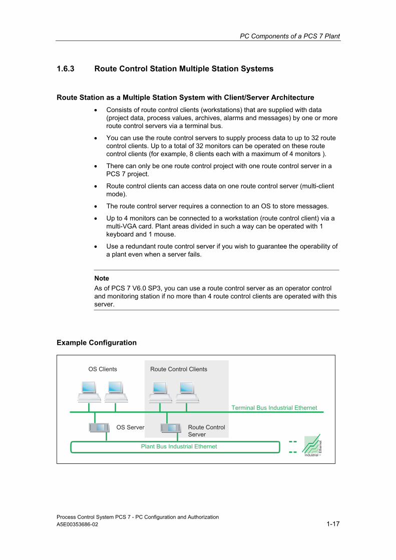
Route Station as a Multiple Station System with Client/Server Architecture • Consists of route control clients (workstations) that are supplied with data
(project data, process values, archives, alarms and messages) by one or more route control servers via a terminal bus.
• You can use the route control servers to supply process data to up to 32 route control clients. Up to a total of 32 monitors can be operated on these route control clients (for example, 8 clients each with a maximum of 4 monitors ).
• There can only be one route control project with one route control server in a PCS 7 project.
• Route control clients can access data on one route control server (multi-client mode).
• The route control server requires a connection to an OS to store messages.
• Up to 4 monitors can be connected to a workstation (route control client) via a multi-VGA card. Plant areas divided in such a way can be operated with 1 keyboard and 1 mouse.
• Use a redundant route control server if you wish to guarantee the operability of a plant even when a server fails.
Note
As of PCS 7 V6.0 SP3, you can use a route control server as an operator control and monitoring station if no more than 4 route control clients are operated with this server.
Example Configuration
Process Control System PCS 7 - PC Configuration and Authorization A5E00353686-02 1-17

PC Components of a PCS 7 Plant
1.6.4 Maintenance Station - Multiple Station System
Maintenance stations are PCs on which the PCS 7 OS software is installed and specially configured for diagnostics.
Distributed systems have the following types of maintenance stations:
• Maintenance server, MS server for short – it concentrates the necessary picture information and data on a PC for the plant diagnostics.
• Maintenance client, MS client for short – it visualizes the diagnostics status using so-called diagnostic pictures and also offer the necessary operator control and monitoring functions for this.
Maintenance Station in a Multiple Station System with Client/Server Architecture • The maintenance station consists of the MS clients (workstation) that is
supplied with data (project data, archives, alarms and messages) by an MS server via a terminal bus.
• The MS client is already integrated in the engineering station.
• The MS server requires a connection to an OS server if it installed on a separate PC.
• Up to 4 monitors can be connected to a workstation (MS client) via a multi-VGA card. Plant areas divided in such a way can be operated with 1 keyboard and 1 mouse.
Example Configuration
Process Control System PCS 7 - PC Configuration and Authorization 1-18 A5E00353686-02

PC Components of a PCS 7 Plant
Installation Maintenance Stations • The MS server is an OS server configured for plant diagnostics. An OS server
must be installed for this.
• The MS client is a component of the engineering station. Information about configuration is available in the configuration manual, Process Control System PCS 7, Operator Station.
• Installation - see section: How to Install the PCS 7 Software
Configuration • Multiple workstation system with:
- MS server
- MS client on the engineering station
Further Information • Refer to the configuration manual, Process Control System PCS 7, Operator
Station.
• See Appendix, "Approved Configurations"
Process Control System PCS 7 - PC Configuration and Authorization A5E00353686-02 1-19

PC Components of a PCS 7 Plant
1.6.5 Long-term Archiving with the Central Archive Server
Introduction The central archive server is used for long-term archiving diverse plant data from PCS 7 in a central database. The central archive server enables you to manage swapped-out SIMATIC BATCH measured values and messages from the OS archives, OS reports and Batch data. These data are provided regardless of the PCS 7 run-time systems. This way, you are able to view all data in a clearly arranged way using the Internet Explorer.
Functions The central archive server is used to
• Archive messages and measured values from PCS 7 OS as of PCS 7 V6.0
• Archive PCS 7 OS reports as of PCS 7 V6.0
• Archive batch data from SIMATIC BATCH as of PCS 7 V6.0
• Swap out all archive data to external storage media
• Catalog all archive data
• Visualize messages using filter functions
• Visualize measured values via filter functions in graphs and tables
• Export measured values, for example, to Excel
• Visualize the archive data of a batch
• Display web-based archive data
Access protection You can set access protection with user-specific rights on the central archive server.
Installation • The central archive server must be installed on a separate PC for performance
reasons. A RAID system is recommended for data security.
• Make sure you can store data on a long-term medium (for example, CD or DVD) using this PC .
Process Control System PCS 7 - PC Configuration and Authorization 1-20 A5E00353686-02

PC Components of a PCS 7 Plant
1.6.6 Access to the PCS 7 OS over Web Client
Web Server and Web Client PCS 7 provides the option of using operator control and monitoring functions of the PCS 7 OS in process mode over the Internet or Intranet. This requires the following components:
• Web server: A separate Web server is set up that provides the Web client with all necessary OS pictures.
• Web client: The Web client is a computer capable of operating over the Internet with the Internet Explorer from which the users can log on. Up to 50 Web clients can access a Web server.
How the Web Client Works Users log in with the Web server in the Internet Explorer and can then use all the functions according to their user rights (setting in the WinCC-Editor "User Administrator"). All operations made on the Web client are logged automatically with the name of the plant operator.
The Web client offers, for example, the following functions:
• Execution of all operator control and monitoring functions that can also be used on an OS client
• Message list calls Message lists can be called up user-specific, just as on an OS client, and the messages acknowledged user-specific.
• Display of the picture hierarchy according to the plant hierarchy
• Use of group display functions including the loop-in-alarm function.
• Use of the expanded status display
Note
Not all functions are available. You will find more detailed information on the availability of the functions in the function manual Process Control System PCS 7; OS Web Option.
Further Information • See manual Process Control System PCS 7; PCS 7 OS Web Option
Process Control System PCS 7 - PC Configuration and Authorization A5E00353686-02 1-21
PC Components of a PCS 7 Plant
1.7 Solutions with Single Station Systems
1.7.1 OS Single Station
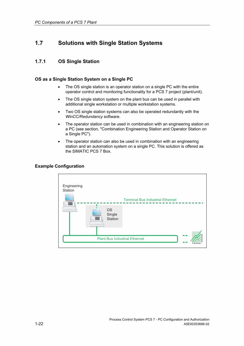
OS as a Single Station System on a Single PC • The OS single station is an operator station on a single PC with the entire
operator control and monitoring functionality for a PCS 7 project (plant/unit).
• The OS single station system on the plant bus can be used in parallel with additional single workstation or multiple workstation systems.
• Two OS single station systems can also be operated redundantly with the WinCC/Redundancy software.
• The operator station can be used in combination with an engineering station on a PC (see section, "Combination Engineering Station and Operator Station on a Single PC").
• The operator station can also be used in combination with an engineering station and an automation system on a single PC. This solution is offered as the SIMATIC PCS 7 Box.
Example Configuration
Process Control System PCS 7 - PC Configuration and Authorization 1-22 A5E00353686-02

PC Components of a PCS 7 Plant
1.7.2 BATCH Single Station
BATCH as a Single Station System on a Single PC • The BATCH single station is a BATCH station on a single PC. The complete
operator control and monitoring functionality is made available for a process cell. Only one BATCH project (plant/unit) always belongs to a BATCH single station.
• A connection to an operator station (OS server) is required for data communication with the automation system.
• A BATCH single station enable operator control and monitoring of a complete plant. When several plants are operated in parallel, an additional BATCH Single Station in needed for each plant with the corresponding connection to the OS server. BATCH multiple station systems are recommended for monitoring several plants.
• When several BATCH single stations are used, each BATCH single station requires a connection to another OS system.
Example Configuration
Process Control System PCS 7 - PC Configuration and Authorization A5E00353686-02 1-23

PC Components of a PCS 7 Plant
1.7.3 Route Control Single Station
Route Control as a Single Station System on a Single PC • The route control single station is a route control station on a single PC that is
used for automation of the material and product transport in PCS 7 plant.
• Route Control single workstation systems can be operated redundantly.
Note
If Route Control single-station systems are used parallel to other Route Control systems, be sure to separate the areas that are controlled by the respective systems.
Example Configuration
1.7.4 SIMATIC PCS 7 BOX Station
See section: "Notes on SIMATIC PCS 7 BOX"
Process Control System PCS 7 - PC Configuration and Authorization 1-24 A5E00353686-02

PC Components of a PCS 7 Plant
1.8 Connecting the PC Stations
1.8.1 Bus Connection between AS, OS, BATCH, RCS and ES
In PCS 7, the communication between and among the AS, OS, BATCH, RCS and ES components is carried out through a bus system (Industrial Ethernet). This is generally assigned to the following busses:
Bus for communication between the following components
Terminal bus • Operation and monitoring systems (OS, BATCH, RCS) • Engineering station • Components on a higher level (such as MES, office networks)
Plant bus • Servers (OS, RCS) and automation systems • The automation systems (SIMATIC connections)
Example Configuration
Further Information For information cabling and network components as well as the potential distances that can be bridged by a PCS 7 plant, refer to the configuration manual, Process Control System PCS 7, Engineering-Station.
Process Control System PCS 7 - PC Configuration and Authorization A5E00353686-02 1-25

PC Components of a PCS 7 Plant
1.8.2 Connection to Terminal/Plant Bus
Connecting OS, BATCH, RCS and ES Communication cards are used to connect operator stations, BATCH stations, route control stations and engineering stations to Industrial Ethernet. The communication cards use a slot in the PC/PG. Various types of communication are employed depending on the requirements.
The section, "Components for Connecting to the Terminal/Plant Bus, offers an overview of the communication cards that can be used".
Example Configuration
Redundant Terminal Bus As of PCS 7 V6.1 SP1 a redundant, fault-tolerant terminal bus is available (For set up and installation see the "How to Install the Driver for the Redundant Terminal Bus" section.).
Connection of the AS The automation systems are connected to Industrial Ethernet using the CP 443-1 communication processor. TCP/IP, ISO and UDP are the protocols used.
Further Information For information cabling and network components as well as the potential distances that can be bridged by a PCS 7 plant, refer to the configuration manual, Process Control System PCS 7, Engineering-Station.
Process Control System PCS 7 - PC Configuration and Authorization 1-26 A5E00353686-02

PC Components of a PCS 7 Plant
1.8.3 Time Synchronization
Time Synchronization A process control system is synchronized when all of the individual components relying on the time have an identical date and identical time-of-day.
Synchronizing Time Throughout the System The ability to evaluate the process data requires that all the components of the process control system work with an identical time so that messages can be inserted in the correct sequence - irrespective of the time zone in which they arise.
To this purpose for example, an OS server has to assume the function of the time master so that all the remaining operator stations and automation systems receive the time from this master and thus have the identical time.
The time synchronization is carried out over both busses in a plant:
• Terminal bus – the OS clients get their time here. In a Windows domain the domain controller can send the time to the OS server that is currently acting as the active time master.
• Plant bus – the CPs of the OS server that are currently passive time masters get their time here. The automation systems are synchronized at the same time from this source.
Synchronization Options
Station Synchronization Options Further Information
Operator Station and Maintenance Station
• Synchronize the time of day through the terminal bus
• Synchronize the time through the plant bus
Configuration manual Process Control System PCS 7; Operator Station
BATCH Station • Synchronize the time through the operating system
Synchronize SIMATIC BATCH components using resources of the operating system
Route Control Station
• Synchronize the time through the operating system
Synchronize route control station components using resources of the operating system
SIMATIC PCS 7 BOX
• Synchronize the time during integration in a PCS 7 plant
Process Control System PCS 7, SIMATIC PCS 7 BOX
AS • Synchronize the time with the AS as the time master or
• Synchronize the time with the AS as the time slave
Configuration manual Process Control System PCS 7; Engineering Station
Domains • Synchronize the time with a domain controller as the time master on the terminal bus
Configuration manual Process Control System PCS 7; Operator Station
Process Control System PCS 7 - PC Configuration and Authorization A5E00353686-02 1-27

PC Components of a PCS 7 Plant
Process Control System PCS 7 - PC Configuration and Authorization 1-28 A5E00353686-02

2 Hardware for PC Stations
PC Hardware for ES/OS/BATCH/RCS/IT A selected range of basic equipment is available for engineering stations, operator stations, BATCH stations, route control stations and for connecting SIMATIC PCS 7 to the IT world:
• Basic hardware (PC base unit) and
• Color monitor - we recommend monitors with a resolution of 1280 x 1024 or higher so that you can take full advantage of the potential offered by the PCS 7 software.
Note
At least one DVD drive must be available in the network to install PCS 7.
Recommended Basic Hardware We recommend the following equipment for PC components (better equipment provides an advantage). The following is the minimum hardware requirements should be met for small projects created with PCS 7:
PC Station Clock rate
Recommended / minimum
Main memory (RAM) Recommended /
minimum
Hard Disk Recommended /
minimum
Engineering Station 2.8 GHz / 1 GHz 1 GB / 768 MB 120 GB / 40 GB OS Single Station 2.8 GHz / 1 GHz 1 GB / 768 MB 120 GB / 40 GB OS Server 2.8 GHz / 1 GHz 1 GB / 768 MB 120 GB / 40 GB Central archive server 2.8 GHz / 2.8 GHz 1 GB / 1GB 120 GB / 120 GB OS Client 2.8 GHz / 866 MHz 512 MB / 512 MB 80 GB / 40 GB OS Web Server 2.8 GHz / 1 GHz 1 GB / 768 MB 120 GB / 40 GB Maintenance server 2.8 GHz / 2 GHz 1 GB / 1GB 120 GB / 40 GB BATCH Single Station 2.8 GHz / 2 GHz 1 GB / 1GB 120 GB / 60 GB BATCH Server 2.8 GHz / 2 GHz 1 GB / 1GB 120 GB / 60 GB BATCH Client 2.8 GHz / 866 MHz 512 MB / 512 MB 80 GB / 40 GB BATCH and OS Client 2.8 GHz / 2 GHz 1 GB / 1GB 80 GB / 40 GB Route Control Single Station 2.8 GHz / 2 GHz 1 GB / 768 MB 120 GB / 40 GB Route Control Server 2.8 GHz / 2 GHz 1 GB / 768 MB 120 GB / 40 GB Route Control Client 2.8 GHz / 866 MHz 512 MB / 512 MB 80 GB / 40 GB
Process Control System PCS 7 - PC Configuration and Authorization A5E00353686-02 2-1

Hardware for PC Stations
Note • Engineering station PCs with higher clock rates, more RAM and larger hard
disks are advantageous for multiproject engineering. Faster disk drives also provide an advantage in this case.
• Central archive servers profit from more RAM.
• For BATCH servers, we recommend clock rates higher than 2 GHz or the use of dual processor systems.
Network The network for PCS 7 systems must be isolated by switches, routers or Gateways to prevent interference in the PCS 7 network from office networks, for example.
Latest Information in PCS 7 Readme Files Please read the latest information provided in the pcs7-readme file on the PCS 7 Toolset DVD that is supplied with every new version and service pack of PCS 7.
Process Control System PCS 7 - PC Configuration and Authorization 2-2 A5E00353686-02

Hardware for PC Stations
2.1 Preconfigured PC Systems for PCS 7 (Bundles)
Basic Hardware Siemens offers special versions of the basic hardware (bundles) for all PC stations. The bundles are optimized for their intended applications (for example, engineering stations, operator stations, SIMATIC PCS 7 BOX etc.).
SIMATIC PCS 7 BOX Basic Hardware SIMATIC PCS 7 BOX is an industrial PC with an integrated AS/ES/OS station. The AS is based on the standard CPU 416-2 PCI. SIMATIC PCS 7 Box is used for autonomous small plants or combined AS/OS stations that can be integrated in the PCS 7 network.
Hardware: See the manual, Process Control System PCS 7; SIMATIC PCS 7 BOX.
Monitors The Siemens industrial monitor range SCD, SCM and CRT are available for the PCS 7 process monitors. These are selected based on the ambient temperature of the plant.
Up to 4 monitors can be connected to a workstation (e.g. OS client) via a multi-VGA card. Plant areas divided in such a way can be operated with 1 keyboard and 1 mouse.
Further Information • Catalog ST PCS 7
• Catalog ST PCS 7.A (Add-ons for SIMATIC PCS 7)
Process Control System PCS 7 - PC Configuration and Authorization A5E00353686-02 2-3

Hardware for PC Stations
2.2 Components for Connecting to the Terminal/Plant Bus
Connecting OS, BATCH, RCS and ES Communication modules are used to connect operator stations, BATCH stations, route control stations and engineering stations to Industrial Ethernet. The communication modules use one expansion slot in the PC/PG. A variety of communication modules can be used depending on the requirements:
• Standard communication modules without processors are sufficient for connecting up to 8 automation systems (downstream from an operator station) (Basic Communication Ethernet - BCE). Connection can also be made via:
- The Ethernet card provided in the PC/PG or
- CP 1612 with SOFTNET-S7/Windows software
- CP 1512 with SOFTNET-S7/Windows software
• If the maximum number of 8 automation systems per operator station is not enough or is fault-tolerant automation systems are to be connected, communication modules with onboard processors can be used:
- CP 1613 with S7-1613 software or
- CP 1613 with S7 REDCONNECT software for redundant communication with S7-400H/FH
Note
Communication can be established with up to 64 automation systems (including redundant systems) using CP 1613.
Drivers The driver software for the communication modules described above is available on the PCS 7 Toolset DVD (see the section, "Additional Devices and Drivers for PCS 7").
Clock Synchronization CP 1613 supports clock synchronization on Industrial Ethernet (Fast Ethernet). A PC with a CP 1613 can receive time of day frames from the following time transmitters:
• SIMATIC S7-400/H/FH with CP 443-1
• SIMATIC NET time transmitter for Industrial Ethernet (see Catalog IK PI)
• SIMATIC SICLOCK
• PC with CP 1613
Process Control System PCS 7 - PC Configuration and Authorization 2-4 A5E00353686-02

Hardware for PC Stations
2.3 Other Optional Hardware Components
Components Application
Smart card reader You can control access to operator stations using smart cards. Each person with access rights requires a smart card.
Printer For printing out logs and reports on all graphic-capable printers supported by the operating system
Signal module OS single station system and OS clients can be expanded with signal modules. These signal modules can control up to 3 external sensors (for example, acoustically with horns or optically with indicator lights) that represent the various message classes. Using a hardware timer (watchdog), the signal modules can detect and signal the failure of an operator station. One PCI expansion slot in the PC station is needed to connect the signal module.
Sound card OS single station system and OS clients can be expanded with a standard sound card. Files (waves, for example) can be reproduced using appropriate devices (speakers, piezo transducers) through the signal module.
Radio clock For synchronizing the PCs (and the plant bus) Intrinsically safe HMI unit
When necessary, an intrinsically safe PC operator control unit (add-on product) can be used in hazardous areas, zone 1 or 2 - distances up to 750 m are possible.
Multi VGA cards You can install a multi-VGA graphics card in a PC used as a: • Engineering station or • Client for an operator station or SIMATIC Route Control. This means that up to 4 monitors can be connected to a PC (for clients and engineering PCs).
Process Control System PCS 7 - PC Configuration and Authorization A5E00353686-02 2-5
Hardware for PC Stations
2.4 Configuring and Ordering
Configurator Software On the Interactive Catalog CD CA01; Automation and Drives, you will find configuration software that you may find useful when putting together your PC network.
Ordering Information In the Process Control System PCS 7; Catalog ST PCS 7 you can find the ordering information for tested PC configurations and software components. The available components represent the optimum basis for all applications in your system (fully installed solutions).
Customer-specific Solutions If you require customer-specific solutions for PC systems (for example for RAID systems), please contact the Siemens configuration service:
Configuration Service Siemens AG, A&D SE SH 2 Software and Systems House - Industrial IT Frauenauracher Strasse 80
D-91056 Erlangen
Process Control System PCS 7 - PC Configuration and Authorization 2-6 A5E00353686-02

3 Installing the PC Stations
3.1 Overview of the Installation Procedure
Introduction The following presents a practical outline of the basic procedure for installing PC stations for PCS 7.
Siemens AG also offers training courses on PC administration. Please contact your regional training center or the central training center for further information (address: see preface).
Overview of the Individual Steps for Installation This overview shows the recommended sequence of individual steps for installation.
Step What?
1 Installing the Operating System 2 Installing Service Packs for the Operating System 3 Making the System Settings 4 Installing the Internet Explorer 5 Installing the Message Queuing Service 6 Installing the Microsoft SQL Server 7 Installing Additional Components 8 Creating a Backup - see the section, "Backup by Creating an Image File" in the Process
Control System PCS 7; Service Support and Diagnostics manual. 9 Installing the PCS 7 Software 10 Installing the Interface for the Plant/Terminal Bus 11 Licensing and Authorization of the PCS 7 Software 12 Preparing PC Stations - An Overview 13 Creating a Backup - see the section, "Backup by Creating an Image File" in the Process
Control System PCS 7; Service Support and Diagnostics manual.
Process Control System PCS 7 - PC Configuration and Authorization A5E00353686-02 3-1

Installing the PC Stations
3.2 Hard Disk Partitioning
Partitioning the Hard Disks To make data backup easier, you should divide your PC station hard disks into partitions:
• For the operating system and the PCS 7 installation: approx. 20 GB
• For PCS 7 project structures: More than 15 GB, possibly several partitions
• For backups: Backups should be made on media that are not affected by failure of the PC or the hard disk containing the original data, for example, on CD, MOD or perhaps on a network.
Example Example for a hard disk with 40.0 GB:
Drive letter
Size in GB
Drive name Formatting Used for
C: 20 SYSTEM NTFS Operating system installation and PCS 7 installation
D: 20 Data NTFS PCS 7 project data ... ... BACKUP NTFS Backup files
Reserving the Required Hard Disk Space for SIMATIC BATCH • SIMATIC BATCH software
You will require approx. 60 MB of free space for installing files on the hard disk of a BATCH station.
• SIMATIC BATCH database If you make a standard installation of SIMATIC BATCH, databases are created in the following folders:
Database Drive folder: Required hard disk space Dictionary (schema) database
....\Siemens\BATCH\sbdata\ global\dict\...
Approx. 1-2 Mbytes
Global database ....\Siemens\BATCH\sbdata\ SB6_xxxxxxxxxx\offline\...
Approx. 1-2 Mbytes
Offline database ....\Siemens\BATCH\sbdata\ SB6_xxxxxxxxxx\online\...
Dependent on the size of the process cell data, recipes, and library objects
Online database ....\Siemens\BATCH\sbdata\ SB6_xxxxxxxxxx\project\...
Dependent on the size of the process cell data and number of batches
• Restoring data To restore the data following a system problem, SIMATIC BATCH creates a database recovery file.
- This file grows depending on the actions performed on the database.
- The size of the file can be restricted.
Process Control System PCS 7 - PC Configuration and Authorization 3-2 A5E00353686-02

Installing the PC Stations
3.3 Installing the Operating System
3.3.1 Notes on Installing the Operating System
Introduction The operating system should only be installed by suitably qualified personnel (this applies in particular to installation of servers and networks).
Integration in Networks You can integrate PC stations for PCS 7 in a network. Note the following in this regard:
Note
Never use a PC station as a server (OS server, BATCH server, RCS server) for domain management (for example, DHCP server, DNS server).
If a server (OS server, BATCH server, RCS server) is also expected to process these services as a server, this can lead to overload of the resources of the PC and cause problems in the operation of PCS 7.
Attention
Only the software products listed in this manual should be installed on a PCS 7 PC. This applies in particular to a runtime PC (OS, SIMATIC BATCH).
Installing programs that have not been approved by Siemens departments and running these programs at the same time can have a negative influence on the PCS 7 system response.
The user is solely responsible for such influences.
If you nevertheless require non-PCS 7 products, these should be installed before you install PCS 7. In this case, make sure that PCS 7 and the "other" products are not active at the same time.
Note about Windows 2000
Note the following when installing an OS PC that you wish to integrate in a domain:
• The Message Queuing services should only be installed after the PC has been integrated in the domain.
• The Message Queuing services have to be reinstalled when the PC is integrated in the domain at a later time.
Process Control System PCS 7 - PC Configuration and Authorization A5E00353686-02 3-3
Installing the PC Stations
New Installation and Update Note the following general information in regard to updating software.
Attention
• If the operating system for PCS 7 is not yet installed on the PC station, changing the operating system will involve reinstalling the PC.
• Check the suitability of your hardware before performing a new installation (see also the pcs7-readme file).
• Transfer your authorizations back to the original disks.
• Before reinstalling the unchanged project, make a backup of the project and the data belonging to it (perhaps by creating an image, refer to the manual, Process Control System PCS 7; Service Support and Diagnostics).
• Make the preparations for updating the software (see the manual, Process Control System PCS 7; Software Updates).
• Save the software necessary for the software update.
• Format the hard disks and create new partitions.
Operating Systems We have developed different procedures depending on the operating system:
• For installation of Windows XP Professional and Windows Server 2003
• For installation of Windows 2000 (Professional and Server)
For the operating systems that can be used for PCS 7: see Appendix "Software Packages and Required Authorizations").
Note
The Windows 2000 Professional and Windows 2000 Server operating systems are not recommended for a new configuration of a PCS 7 network.
When PCS 7 networks are expanded, a mixed configuration is preferable for a network with "one" operating system (Windows 2000 or Windows XP/Windows Server 2003).
The central archive server has only been released for Windows Server 2003.
Server Name without Underscore An underscore should never be used in the names of server PCs. If an underscore is is used in a name, problems may arise when accessing the data using StoragePlus WebViewer. You can see the names of the server PCs in the Windows Control Panel under "System" in the "Network Identification" tab (Windows 2000) or in the "Computer Names" tab (Windows XP).
Process Control System PCS 7 - PC Configuration and Authorization 3-4 A5E00353686-02
Installing the PC Stations
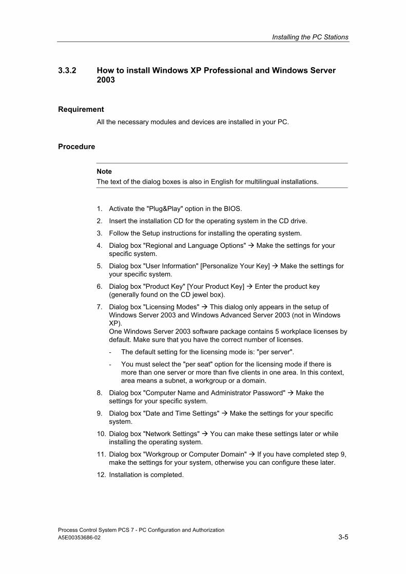
3.3.2 How to install Windows XP Professional and Windows Server 2003
Requirement All the necessary modules and devices are installed in your PC.
Procedure
Note The text of the dialog boxes is also in English for multilingual installations.
1. Activate the "Plug&Play" option in the BIOS.
2. Insert the installation CD for the operating system in the CD drive.
3. Follow the Setup instructions for installing the operating system.
4. Dialog box "Regional and Language Options" Make the settings for your specific system.
5. Dialog box "User Information" [Personalize Your Key] Make the settings for your specific system.
6. Dialog box "Product Key" [Your Product Key] Enter the product key (generally found on the CD jewel box).
7. Dialog box "Licensing Modes" This dialog only appears in the setup of Windows Server 2003 and Windows Advanced Server 2003 (not in Windows XP). One Windows Server 2003 software package contains 5 workplace licenses by default. Make sure that you have the correct number of licenses.
- The default setting for the licensing mode is: "per server".
- You must select the "per seat" option for the licensing mode if there is more than one server or more than five clients in one area. In this context, area means a subnet, a workgroup or a domain.
8. Dialog box "Computer Name and Administrator Password" Make the settings for your specific system.
9. Dialog box "Date and Time Settings" Make the settings for your specific system.
10. Dialog box "Network Settings" You can make these settings later or while installing the operating system.
11. Dialog box "Workgroup or Computer Domain" If you have completed step 9, make the settings for your system, otherwise you can configure these later.
12. Installation is completed.
Process Control System PCS 7 - PC Configuration and Authorization A5E00353686-02 3-5

Installing the PC Stations
Installation of Specific Language Components for a Multilingual Installation 1. Start Setup on the "Multilingual User Interface Pack" CD. 2. Follow the Setup instructions for the installation. 3. Dialog box "Windows Multilingual User Interface Pack" Select the languages
you wish to be available in the menus and dialogs (several languages can be selected). Select the default language. Activate the options "Match language for non-Unicode ..." and "Match the default shell ...".
4. Follow the Setup instructions for the installation. 5. Reboot the PC.
After the Installation of the Windows Multilingual User Interface Pack
The language set is English. 1. Select the following menu command: Start > Control Panel > Regional
Language Options. Result: The "Region and Language Options" dialog opens.
2. Open the "Regional Settings" tab. 3. Make the settings for your specific system. 4. Open the "Languages" tab. 5. Make the settings for your specific system. 6. Open the "Advanced" tab. 7. Make the settings for your specific system. 8. Reboot the PC.
Adding More System Components
1. Select the menu command Start > Settings > Control Panel > Software. Result: The "Software" dialog box opens.
2. Click on the "Add/Remove Windows Components". Result: The "Window Components Wizard" dialog opens.
3. Activate check boxes for the following components in the list:
Option Note
Accessories and Utilities
1. Click on the "Details" button. 2nd Deactivate the check box for "Games" for the Windows XP
installation. Confirm with "OK". IIS - Internet Information Service
• Activate only the services for: - Web Server
• For all other installations, deactivate Message Queuing Services
Activate (Default = deactivated) Settings, see the section, "How to Install the Microsoft Queuing Service".
4. Click on the "Next" button.
5. Confirm the completion of the installation configuration by clicking the "OK" button.
Process Control System PCS 7 - PC Configuration and Authorization 3-6 A5E00353686-02

Installing the PC Stations
3.3.3 How to Install Windows 2000 (Professional and Server)
Requirement All the necessary modules and devices are installed in your PC.
Procedure 1. Activate the "Plug&Play" option in the BIOS.
2. Insert the installation CD for the operating system in the CD drive.
3. Follow the Setup instructions for installing the operating system.
4. Dialog box "Regional Settings" Make the settings for your specific system.
5. Dialog box "Personalize Software" Make the settings for your specific system.
6. Dialog box "Licensing Mode" This dialog only appears in the setup of Windows 2000 Server and Windows 2000 Advanced Server. One Windows 2000 Server software package contains 5 workplace licenses by default. Make sure that you have the correct number of licenses.
- The default setting for the licensing mode is: "per server".
- You must select the "per seat" option for the licensing mode if there is more than one server or more than five clients in one area. In this context, area means a subnet, a workgroup or a domain.
7. Dialog box "Computer Name and Password" Make the settings for your specific system.
8. Dialog box "Windows 2000 Components" This dialog only appears in the setup of Windows 2000 Server and Windows 2000 Advanced Server. Make sure that you activate or deactivate the following options
Option Windows 2000 Server
Accessories Activate (= default) Select Details Games option: Deactivate
Index Services Deactivate (default = activated) IIS - Internet Information Service • Activate only the services for:
- Web Server • For all other installations, deactivate
Message Queuing Services Activate (Default = deactivated) Settings, see the section, "How to Install the Microsoft Queuing Service".
Other options Default
Process Control System PCS 7 - PC Configuration and Authorization A5E00353686-02 3-7

Installing the PC Stations
9. Dialog box "Date and Time Settings" Make the settings for your specific system.
10. Dialog box "Network Settings" You can make these settings later or while installing the operating system.
11. Dialog box "Workgroup and Domain" If you have completed step 7, make the settings for your system, otherwise you can configure these later.
Installation is completed.
If you are installing the server, the operating system will start the dialog for installing the Message Queuing service. Further information, see the section, "How to Install the Message Queuing Service".
Process Control System PCS 7 - PC Configuration and Authorization 3-8 A5E00353686-02

Installing the PC Stations
3.3.4 How to Install Service Packs for the Operating System
Introduction If you installed the operating system without a service pack, the service pack must be installed later.
Versions
Note Refer to the pcs7-readme file to find out which version is required.
Requirement The operating system is installed.
Procedure 1. Insert the installation CD into the drive.
2. Start the installation routine by double-clicking on the appropriate "<operating system>.exe" file.
3. Click the button to accept the license agreement and click the "Install" button.
4. After successful installation, you must restart the computer and remove the installation CD.
Process Control System PCS 7 - PC Configuration and Authorization A5E00353686-02 3-9

Installing the PC Stations
3.3.5 How to Make Additional System Settings
Procedure 1. Set up the users. Open the dialog for the user configuration with the following
menu command: Start > Settings > Control Panel > Administrative Tools > Computer Management > Local Users and Groups.
2. Open the dialog for the display configuration with the following menu command: Start > Settings > Control Panel > Display.
- In the "Settings" tab, set the screen resolution to 1280 x 1024 (for poorer quality monitors or for a larger display, set 1024x768).
- Change to the "Screen Saver" tab.
- Set "None" in the drop-down list box under "Screen Saver".
- For Windows 2000: In "Energy saving features of monitor", click on the "Power" button.
- For Windows Server 2003 and Windows XP Professional: In "Monitor power" section, click on the "Power" button.
- Set "Never" in all the drop-down lists of "Settings for power scheme".
- Close the dialog with the "OK" button.
3. After setting up the network of Windows Server, make sure that all the licenses are available Select the following menu command: Start > Settings > Control Panel > Administrative Tools > Licensing. Go to the "Clients per Seat" tab. There must be no "unlicensed connection" in the system.
4. Activate data throughput for network applications for the Windows Server.
- Windows 2000 Server: Select the following menu command: Start > Settings > Network and Dial-up Connections.
- Windows Server 2003: Select the following menu command: Start > Settings > Network Connections.
- Select the network connection for the terminal bus. Recommendation Name the network connections based on their usage (for example, Terminal bus, Plant bus).
- Select the following menu command: File > Status.
- Open the "General" tab.
- Click on the "Properties" button.
- Select the "File and Printer Sharing for Microsoft Networks".
- Click on the "Properties" button.
- Activate "Maximize data throughput for network applications".
- Close the dialogs with the "OK" button.
5. Deactivate the power saving option for network cards (see the section, "How to Deactivate the Power Saving Options of Network Cards").
Process Control System PCS 7 - PC Configuration and Authorization 3-10 A5E00353686-02

Installing the PC Stations
6. In the Event Viewer check if all services and drivers are functioning correctly: Start > Settings > Control Panel > Administrative Tools > Computer Management > System > Event Viewer.
7. OS Server: Activate the "Optimize performance for background services" option in the Control Panel.
- Select the following menu command: Start > Settings > Control Panel > System. The "System Properties" dialog opens.
- Open the "Advanced" tab.
- In "Performance" section, click on the "Performance Options" button.
- Open the "Advanced" tab.
- For Windows 2000 Server: Activate the check box "Background services" in the "Optimize performance for" section.
- For Windows Server 2003: Activate the check box "Background services" in the "Processor scheduling" section.
- Close the dialogs with the "OK" button.
Process Control System PCS 7 - PC Configuration and Authorization A5E00353686-02 3-11
Installing the PC Stations
3.3.6 How to Install Internet Explorer
Introduction The Internet Explorer is required to operate PCS 7.
Versions
Note Refer to the pcs7-readme file to find out which version is required
Requirement The operating system is installed.
Procedure 1. Insert the installation CD for the Internet Explorer in the CD drive.
- If a dialog box opens automatically, double-click "Install Internet Explorer(6) and Internet Tools". The installation setup is started.
- If the dialog box for installing the Internet Explorer does not open automatically, you must find the Setup on the CD. Open the Windows Explorer and double-click on the "ie(6)setup.exe" file in the CD-ROM drive. (ie6setup.exe = name of the setup file for the "Internet Explorer". Please make sure to install the version mentioned in thepcs7-readme file.)
2. Agree to the license agreement in the Welcome dialog and click the "Next" button.
3. In the next dialog, click the "Next" button again. The installation is started. This can take some time.
4. After successful installation, a final dialog appears. Follow the instructions and then click the "Finish" button. Installation is complete after you reboot the PC.
5. After restarting the PC, you can remove the Installation CD from the drive.
Process Control System PCS 7 - PC Configuration and Authorization 3-12 A5E00353686-02

Installing the PC Stations
3.3.7 How to Install the Message Queuing Service
Introduction The Message Queuing Service must be installed on the PC station before beginning the PCS 7 installation.
Requirements • Installed operating system with service pack and Internet Explorer.
• You must be logged on as the domain administrator to install Windows 2000 Professional, Windows XP Professional and Windows Server 2003.
• You must be logged on as the domain administrator to install Windows 2000 Server.
Message Queuing in an NT 4.0 Domain
Note This requirement does not apply when you are installing or updating Message Queuing on a PC that belongs to a Windows NT 4.0 domain with MSMQ 1.0 controller servers (for example, PEC, PSCs and BSCs). Read the notes regarding this in the Microsoft Windows help for the respective server operating system..
Versions
Note Refer to the pcs7-readme file to find out which version is required.
Process Control System PCS 7 - PC Configuration and Authorization A5E00353686-02 3-13

Installing the PC Stations
Procedure We have developed different procedures depending on the operating system:
• Procedure for Windows XP Professional
• Procedure for Windows Server 2003
• Procedure for Windows 2000 Professional
• Procedure for Windows 2000 Server
Note about Windows 2000 Note the following when installing an OS PC that you wish to integrate in a domain:
• The Message Queuing services should only be installed after the PC has been integrated in the domain.
• The Message Queuing services have to be reinstalled when the PC is integrated in the domain at a later time.
Procedure for Windows XP Professional 1. Select the following menu command: Start > Settings > Control Panel.
2. Double-click on: Add/Remove Programs.
3. Click on the "Add/Remove Windows Components".
4. Select the "Message Queuing" component. The "Details" button is activated.
5. Click on the "Details" button. The "Message Queuing" dialog opens.
6. Activate the subcomponent "General". Deactivate all other subcomponents and confirm with "OK".
7. Click on the "Next" button.
8. If the software for the Message Queuing Service has been saved on the PC together with the operating system, the installation begins immediately. If the software for the Message Queuing Service is not available on the PC, the "Disk:" dialog opens.
- Insert the required Windows installation CD into the drive.
- Click on the "OK" button.
Result: MS Message Queuing is installed.
9. Close the installation program with the "Finish" button.
10. In the Event Viewer check if the Message Queuing Service is functioning correctly:
- Select the menu command Start > Settings > Control Panel > Administrative Tools > Event Viewer.
- Select Event Viewer > Application Log in the tree.
Result: You know the Message Queuing Service is correctly installed when you see the entry MSMQ in the "Source" table column.
Process Control System PCS 7 - PC Configuration and Authorization 3-14 A5E00353686-02

Installing the PC Stations
Procedure for Windows Server 2003 1. Select the following menu command: Start > Settings > Control Panel.
2. Double-click on: Add/Remove Programs.
3. Click on the "Add/Remove Windows Components".
4. Select the line "Application Server" (do not activate the check box) and click on the "Details" button. The "Application Server" dialog opens.
5. Select the line "Message Queuing" (do not activate the check box) and click on the "Details" button. The "Message Queuing" dialog opens.
6. Activate the "Shared Components" check box. Deactivate all other check boxes and confirm by pressing "OK".
7. If the software for the Message Queuing Service has been saved on the PC together with the operating system, the installation begins immediately. If the software for the Message Queuing Service is not available on the PC, the "Disk:" dialog opens.
- Insert the required Windows installation CD into the drive.
- Click on the "OK" button.
Result: MS Message Queuing is installed.
8. Close the installation program with the "Finish" button.
9. In the Event Viewer check if the Message Queuing Service is functioning correctly:
- Select the menu command Start > Settings > Control Panel > Administrative Tools > Event Viewer.
- Select Event Viewer > Application Log in the tree.
Result: You know the Message Queuing Service is correctly installed when you see the entry MSMQ in the "Source" table column.
Procedure for Windows 2000 Professional 1. Select the following menu command: Start > Settings > Control Panel.
2. Double-click on: Add/Remove Programs.
3. Click on the "Add/Remove Windows Components".
4. Select "Message Queuing Services" from dialog window, and confirm with the "Next" button.
5. Activate the option "Independent client" for the "Message Queuing type" (The "Manually select access mode to Active Directory" option button remains deactivated) and confirm with the "Next" button.
6. Activate the option " Message queuing will not access a directory service" in the "Message Queuing Server" dialog box and confirm with the "Next" button.
7. In the Event Viewer of Windows 2000 check if the Message Queuing Service is functioning correctly: Menu command Start > Settings > Control Panel > Administrative Tools > Computer Management > System > Event Viewer.
The entry in the source table is: MSMQ.
Process Control System PCS 7 - PC Configuration and Authorization A5E00353686-02 3-15

Installing the PC Stations
Procedure for Windows 2000 Server 1. Select the following menu command: Start > Settings > Control Panel.
2. Double-click on: Add/Remove Programs.
3. Click on the "Add/Remove Windows Components".
4. Select "Message Queuing Services" from dialog window, and confirm with the "Next" button.
5. Select the option "Message Queuing Server" (the check box remains deactivated) for the "Message Queuing type" and confirm with the "Next" button.
6. Activate the option " Message queuing will not access a directory service" in the "Message Queuing Server" dialog box and confirm with the "Next" button.
7. In the Event Viewer of Windows 2000 check if the Message Queuing Service is functioning correctly: Menu command Start > Settings > Control Panel > Administrative Tools > Computer Management > System > Event Viewer.
The entry in the source table is: MSMQ.
Incorrect function If an error message is displayed in "Description" in the "Event Properties" dialog, the installation is not correct. Uninstall the "Message Queuing Services" and repeat the installation.
If the PC is a member of a domain, check if the Message Queuing Services are installed on the domain controller.
Process Control System PCS 7 - PC Configuration and Authorization 3-16 A5E00353686-02

Installing the PC Stations
3.3.8 How to Install the Microsoft SQL Server
Introduction The Microsoft SQL server is required for the PCS 7 operator stations. The Microsoft SQL server is installed from a separate CD.
Installation and Configuration
Note The installation of the Microsoft SQL Server must be made only in conjunction with the PCS 7 OS installation.
No settings are necessary for PCS 7 - all necessary settings are stored as defaults. The SQL instance for PCS 7 operator station is "WinCC".
Versions
Note Refer to the pcs7-readme file to find out which version of Microsoft SQL server is currently required.
Note SQL Server 2000 is required for PCS 7 using the operating systems, Windows XP and Windows Server 2003.
Requirement The operating system is installed.
Procedure 1. Insert the installation CD for the MS SQL Server in the CD drive. If the start
dialog does not open, change to the CD drive in the Explorer and start the autorun.exe/start.exe file.
2. Select "Install SQL Server 2000" in the dialog.
3. In the Welcome dialog, click "Next". Agree to the license agreement with "Yes". Then click the "Next" button twice and the installation is started.
4. Click the "Finish" button in the final dialog when the installation is complete.
Further information For more detailed information, refer to the installation CD for the "MS SQL Server" in the readme file. The readme file (for example, sp3readme.htm for Service Pack 3) is located in the following folder: SQL-Server 2000: Products > MSSQLServer2000_SP3.
Process Control System PCS 7 - PC Configuration and Authorization A5E00353686-02 3-17

Installing the PC Stations
3.3.9 Installing Additional Components
You need to install additional Microsoft components for some PC configurations. These components are on the PCS 7 Toolset DVD in the "Microsoft" folder.
Note
When a Microsoft component needs to be installed for PC configuration, read the latest information about this in the pcs7-readme file.
Language Versions
Note Install additional Microsoft components in the language version of the operating system.
Language Language Code Example
German xxx_de.xxx dotnetfx_de.exe English xxx_en.xxx dotnetfx_en.exe French xxx_fr.xxx dotnetfx_fr.exe
Procedure 1. Insert the PCS 7 Toolset DVD in the DVD drive.
2. Select the appropriate folder on the PCS 7 Toolset DVD.
3. Install the components described in the pcs7-readme file.
Process Control System PCS 7 - PC Configuration and Authorization 3-18 A5E00353686-02

Installing the PC Stations
3.3.10 How to Set the Language for a User (MUI)
These settings can only be made when an operating system with a Multilanguage User Interface is installed.
Note
For the installation of the central archive server and StoragePlus, the logged on user must use the same language as that set for the default user or the default user profile.
Procedure 1. Select the menu command Start > Settings > Control Panel.
2. Double-click on Region and Language Options.
3. Open the "Languages" tab.
4. Select the desired language from the "Language used in menus and dialogs" in the drop-down list.
Note
Only installed languages are offered in the drop-down list.
Process Control System PCS 7 - PC Configuration and Authorization A5E00353686-02 3-19
Installing the PC Stations
3.3.11 How to Configure the Server Role for the Central Archive Server
If you use the StoragePlus software package on an OS server, you need to take the following steps on this OS server.
Note
The central archive server has only been released for PC stations with the Windows Server 2003 operating system.
For Windows Server 2003, the configure IIS, ASP.net:
Procedure 1. In the Start menu, select Settings > Server Configuration Wizard.
The "Server Configuration Wizard" opens.
2. Click on the "Next" button.
3. No settings need to be made in this dialog. Click on the "Next" button.
4. In the subsequent dialog, select the entry "Application Server (IIS, ASP.NET)" for the "Server Role". Click on the "Next" button.
5. In the subsequent dialog, place a check mark next to the entry "Enable ASP.NET". Click on the "Next" button.
6. Follow the instructions on the screen.
Process Control System PCS 7 - PC Configuration and Authorization 3-20 A5E00353686-02

Installing the PC Stations
3.3.12 How to Configure Users and User Groups
Introduction You now set up user groups and the users for the PCS 7 applications.
Options for User Management The following distinctions must be made:
• User management in Windows (without SIMATIC Logon)
- User management on a single PC
- User management performed from a central location in Windows (PCs in a domain)
• User management expanded by SIMATIC Logon
Some PCS 7 applications support central user management with SIMATIC Logon from PCS 7 which is based on the basic mechanism of Windows user management. SIMATIC Logon provides the following enhancements for user management:
- User management enhanced by SIMATIC Logon can be performed from a central location in Windows (PCs in a domain)
- User management enhanced by SIMATIC Logon on a single PC
Basic Procedure • The following applies to all configuration options for users and user groups:
The definition of users and user groups (available on the respective Windows server) and the definition of passwords is performed from central location in Windows.
• The following applies to defining user roles with the SIMATIC Logon software:
Users and user groups can be assigned specified roles within some PCS 7 applications (for example, SIMATIC BATCH).
Example: SIMATIC BATCH
- User rights in a user role (global)
- Permitted user roles per computer (for each specific computer)
- Permitted user roles per plant unit (for each specific unit)
• The PCS 7 applications are supplied with the data for the user currently logging on via a central logon service and are informed about changing logons.
Process Control System PCS 7 - PC Configuration and Authorization A5E00353686-02 3-21

Installing the PC Stations
Procedure - How to Create Windows Users and User Groups 1. Select the menu command: Start > Settings > Control Panel >
Administrative Tools > Computer Management > System > Local Users and Groups > Users/Groups.
2. Select the menu command Action > New User/New Group to create all users (with password) and user groups in the Windows network (Windows server).
Requirements for Defining User Roles with SIMATIC Logon • SIMATIC Logon must be installed on every computer containing a PCS 7
application.
• Basic Requirement for Working with SIMATIC Logon: You must create the following groups in Windows 2000: "Logon_Administrator" and "Extended_Logon_Administrator".
Information about Further Procedures • The procedure for configuring user roles and assigning then to defined
Windows user groups using SIMATIC Logon is described in the SIMATIC; SIMATIC Logon.
• The possible supplemental settings for the individual PCS 7 applications is described in the respective documentation for these applications.
3.3.13 Creating a Backup
Recommendation After restarting and testing of the installation, you should perform a backup of the partition where the operating system is installed (see the section, "Backup by Creating an Image File" in the manual, Process Control System PCS 7; Service Support and Diagnostics;). With this backup, you can prepare the PC for further new installations.
Process Control System PCS 7 - PC Configuration and Authorization 3-22 A5E00353686-02

Installing the PC Stations
3.3.14 Setting Color Schemes and Font Sizes
Introduction The settings for the color scheme and font size are sometimes changed automatically when other programs are installed. With certain color schemes and font sizes, this can lead to the faceplates being displayed incorrectly in PCS 7.
Procedure You can correct the settings by making the following entries:
1. Select the following menu command Start > Settings > Control Panel.
2. Double-click on "Display".
Color scheme
1. Select the "Appearance" tab in the "Display Properties" dialog.
2. Make the following settings:
- Select "Desktop" in the "Item" combo box.
- Select the setting "Windows Classic" in the "Scheme" combo box.
- Click on the "Apply" button.
- Select "Active Title Bar" in the "Item" combo box.
- Select the dark blue menu area in the "Color" combo box.
- Select the dark blue menu area in the "2nd Color" combo box.
Font size
1. Select the "Settings" tab in the "Display Properties" dialog.
2. Select "Small Fonts" in the "Font Size" combo box.
Options
1. Select the "Effects" tab in the "Display Properties" dialog.
2. Uncheck the "Show window contents while dragging" option.
3. Confirm with "OK".
Process Control System PCS 7 - PC Configuration and Authorization A5E00353686-02 3-23

Installing the PC Stations
3.4 Installing the PCS 7 Software
3.4.1 Notes on Installing PCS 7
Introduction The PCS 7 software contains the applications with which you can perform plant configuration and monitor and operate in process mode. In addition to the applications of the basic software, there are numerous option packages and upgrade packs that can be installed later and used for special applications.
Refer to the latest ST PCS 7 catalog to learn about all of the software packages released for PCS 7 and how they can be used. The Process Control System PCS 7; Engineering System configuration manual provides a detailed introduction.
The following describes the installation of the basic software.
Versions of the Software Package Please read the latest information on the software package and its versions provided in the pcs7-readme file on the PCS 7 Toolset DVD.
Latest Information on Installation
Note Please read the latest, continually updated notes about installation and software and hardware requirements provided in the pcs7-readme file on the PCS 7 Toolset DVD.
Rules
Attention • Only the software products listed in this manual should be installed on a PC
station for PCS 7. This applies in particular to PC stations for the process mode (OS, BATCH, RCS).
• Installing applications that have not been approved by Siemens and running these applications at the same time can have a negative influence on the PCS 7 system response.
• The user is solely responsible for such influences.
• If you nevertheless require non-PCS 7 products, these should be installed before you install PCS 7. In this case, make sure that PCS 7 and the "other" products are not active at the same time.
Process Control System PCS 7 - PC Configuration and Authorization 3-24 A5E00353686-02

Installing the PC Stations
Several PCS 7 Applications on a PC Station A single PCS 7 PC station can be used to run more than one PCS 7 application (for example, OS server and BATCH client). More detailed information regarding this is available in the Appendix, "Approved Configurations"
Installation of the Archive Server
Note For the installation of the central archive server and StoragePlus, the logged on user must use the same language as that set for the default user or the default user profile.
SIMATIC PCS 7 BOX See section, "Notes on SIMATIC PCS 7 BOX"
Process Control System PCS 7 - PC Configuration and Authorization A5E00353686-02 3-25

Installing the PC Stations
3.4.2 How to Install from the Network
Preparation If you want to install several PCs, you should make the following preparations:
Copy the content of the PCS 7 Toolset DVD to a hard disk that can be accessed by all the PCs. You can install several PCs at one time.
Note
Ensure there is a shortcut to the hard disk where you copy the software package that appears automatically when the PC boots.
Procedure 1. Copy the files from the DVD to a folder.
2. From now on, you work on the PC on which you want to install PCS 7.
3. Open the Explorer and go to the folder in the network where you copied the DVD.
4. Start the Setup program: See section, "How to Install the PCS 7 Software".
3.4.3 How to Install the PCS 7 Software
Introduction The PCS 7 Toolset DVD contains the complete software for the PCS 7 applications. Depending on the PCS 7 application, you may need to install only certain applications from the PCS 7 Toolset DVD. A PCS 7 system setup supports you in this regard.
Authorizations You can handle the required authorizations for the individual software packages in different ways:
• Transfer the authorization after installing PCS 7 (recommended since the installation is not interrupted by operator input required to authorize the software packages.)
• Transfer the authorization during the installation of PCS 7 (this option is offered at the beginning of the PCS 7 system setup)
The "Licensing and Authorization of the PCS 7 Software section contains a description of the licensing concept.".
Process Control System PCS 7 - PC Configuration and Authorization 3-26 A5E00353686-02

Installing the PC Stations
Requirements • The operating system is installed and all the steps described in the "Installation
of the Operating System" section are completed.
• All communication modules are installed in the PC.
Procedure 1. Insert the PCS 7 Toolset DVD in the DVD drive.
2. Start Setup by double-clicking on Setup.exe. Result: Setup starts.
3. Work through the dialog boxes in the following order:
Step Setting Note on the Setting
1. Setup language ... for example, "English" and "Next" 2. Welcome ... "Next" 3. Readme ... read this if need be and "Next" 4. Record To log the installation, you can enable the "Record"
function and save the log file to a specified folder. "Next" – Setup searches for programs already installed.
5. Software license agreement
... agree with "Yes"
6. Setup type ... select the option "Install" or "Update" and then "Next".
7. User information Enter the user information and then "Next" 8. License Keys • Insert the floppy with the license keys and enable
the option "Perform license key transfer automatically" or
• Transfer license keys after the PCS 7 installation and "Next"
9. Product Languages Select the options for one or more languages (for example, "English" and "German") and "Next"
10. Installation Type Press the "User-defined Installation" button only if you wish to modify a preconfigured software package for a PCS 7 application and the press "Next".
11. User registration ... Enter name/company/identification number and "Next"
12. Target drive ... select the drive and "Next" 13. Program Packages
(See figure below) ... select the program package and the "Next". Select the software package for the PCS 7 application in the subsequent dialog box. Enable the respective option (approved combinations are described in the section "Approved Configurations"). Result: The software packages installed by default for this PCS 7 application are listed in the window at the lower part of the dialog.
Process Control System PCS 7 - PC Configuration and Authorization A5E00353686-02 3-27

Installing the PC Stations
Step Setting Note on the Setting 14. Ready to install the
selection "Next" Result: The installation of the software package starts and the progress is shown in a window. Note: Another dialog appears shortly after the start of the installation for the central archive server. The required settings are described in the section: "How to Install the Central Archive Server (StoragePlus)".
4. Exit Setup when the installation is complete.
5. Reboot the PC.
Displaying Installed Software You can check which software packages are installed on the PC.: Select the following menu command: Start > SIMATIC > PCS7 > Installed Software. You will find the installed software packages in the "Products" tab.
Process Control System PCS 7 - PC Configuration and Authorization 3-28 A5E00353686-02

Installing the PC Stations
3.4.4 How to Install the Central Archive Server (StoragePlus)
Settings in the "StoragePlus Installation Settings" Dialog When installing a central archive server (StoragePlus servers) with the PCS 7 Toolset DVD, please adhere to the following steps when installing via the set up (see section "How to install the PCS 7 software"):
1. Click on the "Install" button in the Setup dialog "Ready to install the selection". The "StoragePlus Installation Settings" dialog opens.
Note
Settings made in the "StoragePlus Installation Settings" dialog cannot be changed.
2. Make the following settings:
Name of the database: Enter the specific database name for the interim
archive. The interim archive includes the most recently archived process data for a specified time period.
Path of the database: Enter the path to the interim archive on the local hard disk of the server.
Path of the data protocol: Enter the path of the data protocol.
Shared archive directory: Enter the name of the shared archive directory. The shared archive is used as a common location for swapping out the archive segments and reports of the OS server to the central archive server (backup path).
Note about Installation • The names of the database files are derived from the individual database
names as follows:
- Configuration database – name of the database file: DBName.mdf
- Configuration database - name of the database log file: DBName.ldf
- Runtime database - name of the database file: DBName_D.mdf
- Runtime database - name of the database log file: DBName_D.ldf
• If you wish to use an existing database, note that you also have to use the name of the database and corresponding path where it is located.
Process Control System PCS 7 - PC Configuration and Authorization A5E00353686-02 3-29

Installing the PC Stations
The following recommendations for distributing the archives on the partitions provide optimized performance and operating security:
• Do not set the paths for the interim archive or the shared archive directory to the partition containing the Windows operating system.
• Do not locate any other data (the virtual memory file of the operating system, for example) on the following partitions:
- the partition of the shared archive
- the partition of the interim archive, if you have activated the "Fraction of hard disk capacity" option for automatic archiving. This option means that the fill level of the partition depends on the time horizon of the complete archive (i.e. how far in the past you can access the tag logging data).
• Ensure that there is enough free space on the partition for the interim archive so that the OS server can continue to swapped out archive segments even after process mode has ended on the central archive server.
We recommend the following to increase the performance of the archive server when large amounts of data are involved:
• Use an archive server with several hard disks.
• Do not set the path of the database to the physical hard disk where the Windows system is installed.
Increased performance and data security • We recommend the use of RAID systems (RAID 0) to increase the
performance.
• We recommend the use of RAID systems (RAID 1) to improve the data security of the archive server.
Process Control System PCS 7 - PC Configuration and Authorization 3-30 A5E00353686-02
Installing the PC Stations
3.4.5 Activating Redundancy
Additional steps are required to configure redundant stations.
Additional Steps for the Server and Single Station (OS, BATCH) To configure redundant pairs:
1. Connect the PCs with a redundancy cable (null modem cable) via the COM ports of the PCs.
2. Follow the corresponding instructions provided in the function manual, Process Control System PCS 7; Fault-Tolerant Process Control Systems.
Additional Steps for Clients (OS, BATCH) Connect the clients with the redundant servers:
1. Follow the corresponding instructions provided in the function manual, Process Control System PCS 7; Fault-Tolerant Process Control Systems.
Additional steps for SIMATIC Route Control 1. Follow the corresponding instructions provided in the manual, Process Control
System PCS 7; SIMATIC Route Control.
Process Control System PCS 7 - PC Configuration and Authorization A5E00353686-02 3-31

Installing the PC Stations
3.4.6 Reinstallation/Updating
If PCS 7 software packages are already installed on the PC, a dialog relating to the type of installation appears when you run the PCS 7 system setup. In this dialog, you must decide which type of installation you require:
• Installation or
• Update
Installation For a reinstallation, you have the option of installing additional software packages on the PC.
Update For an update, existing software packages are replaced by newer versions of the software. Please make sure that the new versions of the software packages are selected.
Note
If you want to update a PCS 7 project from a previous version of PCS 7, make sure you keep to the procedures for software updates as described in the manuals.
For more detailed information, refer to the manual, Process Control System PCS 7; Software Updates
3.4.7 Removing PCS 7
The PCS 7 uninstall function should only be used to remove the PCS 7 software.
Once the PCS 7 software is removed, we recommend that you format the hard disk and reinstall the PC or load the appropriate image before reinstalling the PCS 7 software.
Process Control System PCS 7 - PC Configuration and Authorization 3-32 A5E00353686-02

Installing the PC Stations
3.5 Installing the Drivers for PCS 7
3.5.1 Drivers for Communication Modules
Introduction The necessary drivers for communication modules are automatically installed during the PCS 7 system setup. This requires that the communication modules to be installed in the PC before the installation PCS 7.
If you change the type of communication module after the installation of PCS 7, you have to reinstall the drivers for the communication modules from the PCS 7 Toolset DVD (software package "SIMATIC NET PC-Software"). This installation procedure is described in the section, "How to Install Drivers for Communication Modules".
Plug-and-Play Compatibility The communication modules used for PCS 7 are Plug-and-Play compatible. The required settings are made automatically when the PC starts up.
Switching the Protocol on the Bus (Industrial Ethernet) If the protocol of a bus in a plant needs to be switched (from TCP to ISO, for example), you need to briefly set a mixed protocol (TCP and ISO) on the engineering station.
The configuration data can then be downloaded to the AS and the HMI systems.
Attention
The TCP/IP and ISO protocols cannot be disabled since they are both needed for the configured operation!
Process Control System PCS 7 - PC Configuration and Authorization A5E00353686-02 3-33

Installing the PC Stations
3.5.1.1 How to Install Drivers for Communication Modules
Requirement
Communication modules must be installed in the PC before the installation.
Procedure
1. Insert the DVD in the DVD drive.
2. Start Setup by double-clicking on Setup.exe. Result: The PCS 7 system setup starts.
3. Work through the dialog boxes in the following order:
Step Setting Note on the Setting
1 Setup language ... for example, "English" and "Next" 2 Welcome ... "Next" 3 Readme ... read this if need be and "Next" 4 Software license
agreement ... agree with "Yes"
5 User registration ... Enter name/company/identification number and "Next"
6 Target drive ... select the drive and "Next" 7 Language of the
software Select the options for one or more languages (for example, "English" and "German") and "Next"
8 Type of installation ... here Reinstallation and "Next"
4. Enable the "User-defined installation" option in the subsequent dialog. Click on the "Next" button.
5. Make the following settings in the subsequent dialog box:
- Enable the "SIMATIC NET PC Software" option.
- Disable all other check boxes.
6. Click "Next". Result: The installation of the software package starts and the progress is shown in a window.
7. Exit Setup when the installation is complete.
8. Reboot the PC.
Note
Additional steps are required when a later installed communication module does not have an onboard processor: See section, "How to Configure Standard Communication Modules".
Process Control System PCS 7 - PC Configuration and Authorization 3-34 A5E00353686-02

Installing the PC Stations
3.5.1.2 How to Configure Standard Communication Modules
Settings for BCE and Softnet CPs If there is a separate BUS (terminal bus and plant bus), we recommend that you select the ISO protocol for the plant bus and disable the TCP/IP protocol.
Note
The selection of the protocol for the plant bus is made during the configuration of the communication modules (preferred CPs) in HW Config and/or NetPro.
Requirements
• PCS 7 is installed.
• There is no communication.
• The user programs are closed.
Procedure
1. Windows Server 2003 and Windows XP: Select the following menu command Start > Settings > Network Connections. Windows 2000: Select the following menu command Start > Settings > Network and Dial-up Connections.
2. Right click on the communication module (connection) to the plant bus for which you wish to disable the TCP/IP protocol and select the "Properties" menu command.
3. Disable the check box "Internet protocol (TCP/IP)" in the area "Components checked are used by this connection" . Confirm your setting by clicking the "OK" button.
You can ignore any messages to the effect that other services ("File and Printer Sharing", "Client for Microsoft Network") can be disabled.
4. For PCs with several network card:
- Select the following menu command: Advanced > Advanced Settings.
- Select the network connection to the terminal bus in the "Connections" section.
- Move the selected network connection to the top position using the arrow keys.
5. Close the dialogs with the "OK" button.
6. Reboot the PC to have the settings take effect.
7. Windows Server 2003 and Windows XP: Select the following menu command Start -> Settings -> Network Connections. Windows 2000: Select the following menu command Start -> Settings -> Network and Dial-up Connections.
Process Control System PCS 7 - PC Configuration and Authorization A5E00353686-02 3-35

Installing the PC Stations
8. Make the following settings for the communication module on the plant bus:
- Disable the "Client for Microsoft Network" option.
- Disable the "File and Printer Sharing for Microsoft Networks" check box.
9. Close the dialogs with the "OK" button.
Note
Read the notes in the WinCC Information System: "Special Communication Features Using Servers with Several Network Cards".
3.5.1.3 How to Disable the Power Saving Options of Network Cards
Check if your network card supports Windows power management.
The activated power saving option on a PCS 7 PC can (after approx. 4-6 hours) trigger a restart of the PC and must therefore be disabled.
Procedure 1. Windows 2000 Server: Select the following menu command: Start > Settings
> Network and Dial-up Connections. Windows Server 2003: Select the following menu command: Start > Settings > Network Connections
2. Select the network connection.
3. Select the following menu command: File - Properties.
4. Open the "General" tab.
5. Click on the "Configure" button.
6. Check in all the displayed tabs if the PC can disable the network card in order to save power and disable the power saving function if this is the case.
Process Control System PCS 7 - PC Configuration and Authorization 3-36 A5E00353686-02

Installing the PC Stations
3.5.1.4 How to Activate Redundancy for Redundant OS/BATCH Servers If SIMATIC BATCH Server and PCS 7 OS Server are to be installed on one server pair in a plant with separate terminal bus and plant bus, an additional network adapter is needed for redundancy communication. The following steps need to be taken on each computer in the server pair.
Settings for the Third Network Adapter 1. Open network connections with the menu command Start > Settings >
Control Panel > Network and Dial-up Connections. 2. Select the menu command Advanced > Advanced Settings.
The terminal bus must be at the top of the connections list. Place the third network adapter below the terminal bus in the list.
3. In the "Adapters and Bindings" tab, deactivate the "Client for Microsoft Networks" and "File and Printer Sharing ..." options for the third network adapter.
4. Click the "OK" button to save your settings. 5. In the list of connections, select the "3rd network adapter" and select the menu
command File > Properties. 6. Activate the "Internet Protocol (TCP/IP)" check box and deactivate all other
elements: 7. Select "Internet Protocol (TCP/IP)" and press the "Properties" button. 8. Set the "local" IP address in the "General" tab. 9. Click the "OK" button to save your settings. 10. Enter the same IP address in the SIMATIC BATCH configuration dialog
("Settings" button > "Startup" tab):
11. Click on the "OK" button to save the settings.
Process Control System PCS 7 - PC Configuration and Authorization A5E00353686-02 3-37

Installing the PC Stations
3.5.1.5 How to Install the Driver for the Redundant Terminal Bus As of PCS 7 V6.1 SP1, the following possibilities are offered for configuring terminal busses: • Fault-tolerant terminal bus in a ring topology (standard solution) • Redundant, fault-tolerant terminal bus (all network components are connected
via two network adapters to the autonomously operating terminal bus rings) The following describes how to configure a redundant, fault-tolerant terminal bus.
Hardware configuration The following two network adapter should be used in each PC to be connected to the terminal bus (for example, OS server, OS client, engineering station, domain controller): • Server adapter Intel Pro/1000MT • Desktop adapter Intel Pro/1000GT Two OSMs (100 Mbps) built into one of the redundant rings are used to connect the redundant rings. The following switches can be set: • SCALENCE X204-2 • OSM TP62 • SCALENCE X414-3E (the following media module must be set for the
SCALENCE X414-3E: SCALENCE X414-3E Fast-Ethernet media modules MM491-2 (100Base-FX) )
O S MO S MO S M T P 6 2
O S MO S MO S M T P 6 2
Process Control System PCS 7 - PC Configuration and Authorization 3-38 A5E00353686-02

Installing the PC Stations
Software The configuration and installation of the two network adapters are performed in the ProSet tool from Intel.
The drivers for the redundant network adapters used with PCS 7 are available in the following directory on the PCS 7 Toolset DVD as of version 6.1 SP1: Additional_Products > Drivers > Network > Intel.
Overview of required tasks: 1. Installing the network adapter
2. Installing the driver
3. Configuring the driver
Function Each network adapter is connected to one of the redundant terminal bus rings. The network adapters operate in "Team mode: Switch Fault Tolerance" with only one logical network address. The team has an IP address. Only one network adapter is active at any one time.
Procedure – installing the driver 1. Install the driver for the network adapter:
Double-click on "Autorun.exe" file in the root directory of the storage medium, for example, D:\Autorun.exe).
Procedure – configuring the driver Perform the following to configure the network adapter:
1. Select the menu command Settings > Control Panel > Administration > Computer Management > Device Manager > Network Adapter.
2. Select the internal network adapter. Using the context menu, deactivate the internal network adapter.
3. Select the server adapter "Inter® PRO/1000 MT Server Adapter". Select Properties from the context menu.
4. In the "Teaming" tab, activate the "Team with other adapters" option. Click on the "New Team" button. The ""New Team Wizard" dialog opens.
5. Click on the "Finish" button. The "Welcome to the Inter® PRO Adapter New Team Wizard" dialog opens.
- Enter a name for the team (for example, "Terminal bus team #0").
6. Click on the "Next" button.
7. In the "Select a team mode" list, select the entry "Switch Fault Tolerance".
8. Click on the "Next" button.
Process Control System PCS 7 - PC Configuration and Authorization A5E00353686-02 3-39

Installing the PC Stations
9. In the "Select the adapters to include in this Team:" list, activate the check box for the network adapters to be used for connecting a server to the redundant terminal busses.
10. Click on the "Next" button. The Wizard closes. The team (for example, "Terminal bus team #0") is now entered in the Properties dialog of the network adapter.
11. Click on the "Properties" button. The "Team: <team name> Properties" dialog opens ("Team: Terminal bus team #0 properties" in our example).
12. Open the "Advanced" tab.
13. Select the entry "Test" from the "Settings" list. Select the entry "enabled" from the "Value" drop-down list.
14. Open the "Settings" tab.
15. Click on the "Modify Team" button.
16. In the "Adapters" tab, select the network adapter on the preferred terminal bus. Click on the "Set Primary" button.
17. Select the network adapter (Desktop adapter Intel Pro/1000GT) on the redundant terminal bus. Click on the "Set Secondary" button. Click on the "OK" button. The "Team: <team name>" dialog closes. The two network adapters and their team membership are now entered in the device manager.
Process Control System PCS 7 - PC Configuration and Authorization 3-40 A5E00353686-02
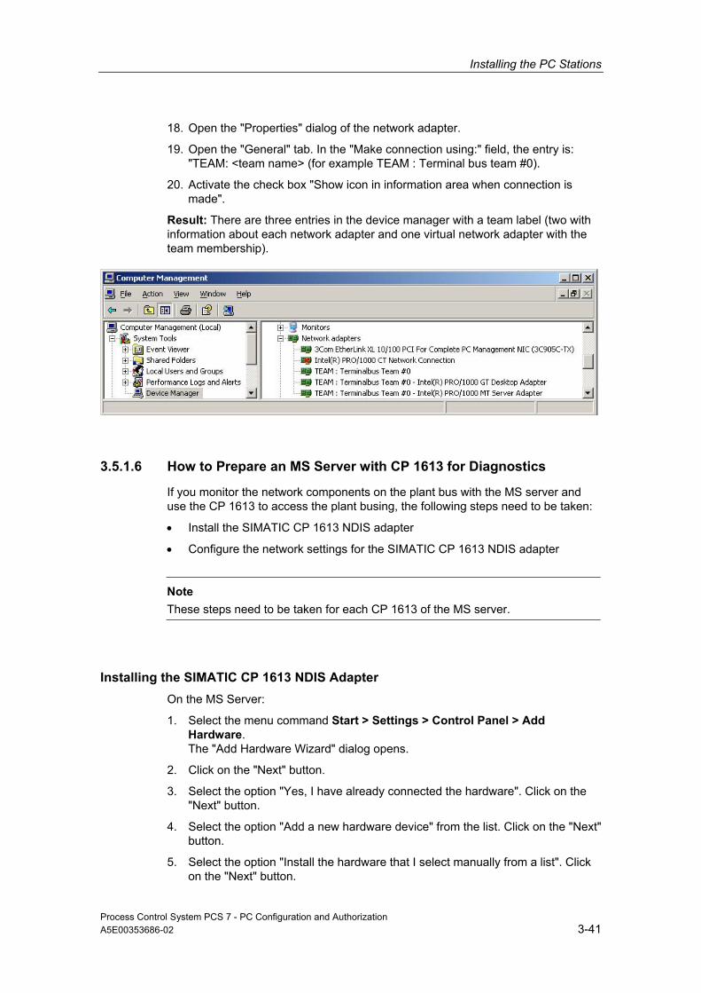
Installing the PC Stations
18. Open the "Properties" dialog of the network adapter.
19. Open the "General" tab. In the "Make connection using:" field, the entry is: "TEAM: <team name> (for example TEAM : Terminal bus team #0).
20. Activate the check box "Show icon in information area when connection is made".
Result: There are three entries in the device manager with a team label (two with information about each network adapter and one virtual network adapter with the team membership).
3.5.1.6 How to Prepare an MS Server with CP 1613 for Diagnostics
If you monitor the network components on the plant bus with the MS server and use the CP 1613 to access the plant busing, the following steps need to be taken:
• Install the SIMATIC CP 1613 NDIS adapter
• Configure the network settings for the SIMATIC CP 1613 NDIS adapter
Note
These steps need to be taken for each CP 1613 of the MS server.
Installing the SIMATIC CP 1613 NDIS Adapter On the MS Server:
1. Select the menu command Start > Settings > Control Panel > Add Hardware. The "Add Hardware Wizard" dialog opens.
2. Click on the "Next" button.
3. Select the option "Yes, I have already connected the hardware". Click on the "Next" button.
4. Select the option "Add a new hardware device" from the list. Click on the "Next" button.
5. Select the option "Install the hardware that I select manually from a list". Click on the "Next" button.
Process Control System PCS 7 - PC Configuration and Authorization A5E00353686-02 3-41

Installing the PC Stations
6. Select "Network adapters" from the list. Click on the "Next" button.
7. Make the following selection:
- In the "Manufacturers" list select "SIEMENS AG".
- In the "Network Adapter" list select "SIMATIC CP1613 NDIS Adapter".
8. Click on the "Next" button.
9. Click on the "Next" button. The installation is carried out.
10. Click on the "Finish" button.
Result: The NDIS adapter is installed.
Configuring Network Settings for the SIMATIC CP 1613 NDIS Adapter On the MS Server:
1. Select the menu command Start > Settings > Network Connections. The "Network Connections" dialog box opens.
2. Select the following menu command View > Details.
3. Right-click on the NDIS Adapter "SIMATIC CP1613 NDIS Adapter". Recommendation Select the command "Rename" from the context menu. Assign a unique name such as CP1613_NDIS_Adapter_No_1. Select the command "Properties" from the context menu.
4. Select the connection "Internet Protocol (TCP/IP)". Click on the "Properties" button. The "Internet Protocol (TCP/IP) Properties" dialog opens.
5. Select the "Use the following IP address" option. Enter the following settings for the project:
- IP address
- Subnet mask
6. Click "OK" to confirm your settings.
7. Close the window for the "(Network Connection) Properties".
Result: The network settings for the NDIS adapter are now in effect.
Process Control System PCS 7 - PC Configuration and Authorization 3-42 A5E00353686-02

Installing the PC Stations
3.5.2 Additional Devices and Drivers for PCS 7
Additional drivers are available on the PCS 7 Toolset DVD if you wish to use special features in PCS 7.
Overview of Additional Devices and Drivers
Application Driver Driver Location on the PCS 7 Toolset DVD
Further information
Multiple monitors on a single PC
Matrox Multi VGA Additional_Products\ Drivers\Display\…
See section, "How to Activate a Multi-VGA Graphics Card"
Acoustic or optical sensors
Horn module Required drivers are installed automatically with PCS 7.
See the configuration manual, Process Control System PCS 7; Operator Station.
Acoustic sensors Sound card Not included on the PCS 7 Toolset DVD – installation medium for sound card or default Windows driver
See section "How to Activate a Sound Card"
Time-of-day signal via DCF77
Time reception service
Additional_Products\ Drivers\DCF77
See section "How to Activate a DCF77 Module"
Smart cards Smart card reader Required drivers are installed automatically with PCS 7.
See WinCC Information System
3.5.2.1 How to Activate a Multi-VGA Graphics Card
Requirements 1. Remove the existing driver for the graphics card current in use (if applicable).
In this situation, an old graphics card is installed or the PC has booted in VGA mode. Menu command: Start > Settings > Control Panel > System > "Hardware" > tab "Device Manager" button
2. Select the graphics card from the folder, "Display adapters".
3. Select the following menu command:
- Windows 2000: Action > Uninstall
- Windows XP and Windows 2003: Action > Uninstall
4. Select the following menu command: Start > Shut Down.
5. Install the Multi-VGA card in the PC.
6. Start the PC.
7. Make the following setting in the PC Setup (BIOS):
- Enable "PCI VGA" as the "Primary Display"
- Enable Plug&Play
Process Control System PCS 7 - PC Configuration and Authorization A5E00353686-02 3-43

Installing the PC Stations
Procedure 1. Reboot the PC.
2. When the Windows message "New hardware found" appears, set the installation path to the path where the drivers for the respective graphics card are located.
3. Install the driver for the Multi-VGA card.
Note
Do not install the driver for any onboard graphics controller at this stage.
4. Select the following menu command: Start > Settings > Control Panel > Display. The "Display Properties" dialog opens.
5. Open the "Settings" tab.
6. Click on the "Advanced" button. The "Properties of Plug and Play Monitor and Matrox ..." dialog opens.
7. Select multiple displays (for example, Dualhead) in the tab.
8. Set the multiple displays.
9. When all of the monitors on the Multi-VGA card are functioning, you can continue with the Windows "New hardware found" dialog and install the driver for any onboard graphics controller. Now enable this newly found but unneeded hardware in the Control Panel's system settings (device manager).
Process Control System PCS 7 - PC Configuration and Authorization 3-44 A5E00353686-02

Installing the PC Stations
3.5.2.2 How to Activate a Sound Card
You can use commercially available sound card to output acoustic messages. The card uses common software to play wave files (*.wav) that continue to sound until the operator provides acknowledgment.
Note
When there are several messages from different message classes, the associated sounds are played simultaneously.
Requirement • A standard sound card is installed.
• Selected wave files are available on the computer. The wave files must support Pulse Code Modulation format. They can be either mono or stereo.
• DirectX is installed.
Procedure Select the following menu command: Start > Settings > Control Panel.
Windows XP:
1. Double-click on: "Sounds and Audio Devices".
2. Select the sound card under "Default device" in the "Audio" tab.
Windows 2000:
3. Double-click on: "Sounds and Multimedia"
4. Select the sound card under "Default device" in the "Audio" tab.
Further information • Configuring and assigning sounds to events: See the configuration manual,
Process Control System PCS 7; Operator Station.
Process Control System PCS 7 - PC Configuration and Authorization A5E00353686-02 3-45

Installing the PC Stations
3.5.2.3 How to Activate a DCF77 Module
Introduction The reception service analyzes the time signals from the DCF77 transmitter of the Physikalisch-technischen Bundesanstalt in Mainflingen in Darmstadt, compares them to the system time of the PC station and corrects it if necessary.
The time signals can be read by a receiver module in different ways. The reception service expects the time signals from the serial port of the PC station.
Note
The "DCF77 Reception Service" application used with the DCF77 module can be employed as a client application to synchronize any number of PCs without the DCF77 module.
Requirement The DCF77 receiver module is connected to an available serial port on the PC station.
Procedure 1. Start SETUP.exe on the installation diskette.
2. Change the settings in the Control Panel if necessary.
Process Control System PCS 7 - PC Configuration and Authorization 3-46 A5E00353686-02

Installing the PC Stations
3.6 Licensing and Authorization
3.6.1 Licensing and Authorization of the PCS 7 Software
Important Terms The following table shows the most important terms relating to licensing and authorization.
Term Description
License A license provides the right to use products. This right takes the form of a • CoL (Certificate of License) and • License key.
CoL (Certificate of License)
The CoL is a proof of the license. The product may only be used by the owner of the license or an authorized person.
License key The license key is the "technical form" of the license (also referred to as an "electronic license stamp").
Authorization The authorization is a "technical representative" of a license that was granted for older versions of the software packages. It has the same function as a license key.
Note
In the following, we will only use the term license key even when an older authorization is used for a product.
License Types There are several license types for products from Siemens AG:
License Type Description
Single license The use of the software with a single license is permitted on any one computer for an unlimited period. The type of usage is defined by the certificate of license.
Floating license The use of the software with a single license is permitted on any one computer for an unlimited period. The usage right can be granted over a network. There is 1 license key for a single computer.
Rental license The use of the software with this license is limited to: • the number of hours stipulated in the agreement • the number of days after first use as stipulated in the agreement • the expiration data as stipulated in the agreement
Process Control System PCS 7 - PC Configuration and Authorization A5E00353686-02 3-47
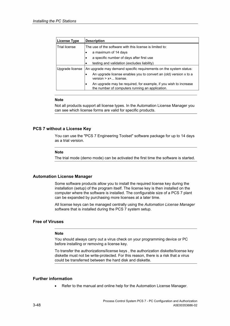
Installing the PC Stations
License Type Description
Trial license The use of the software with this license is limited to: • a maximum of 14 days • a specific number of days after first use • testing and validation (excludes liability)
Upgrade license An upgrade may demand specific requirements on the system status: • An upgrade license enables you to convert an (old) version x to a
version > x+... license. • An upgrade may be required, for example, if you wish to increase
the number of computers running an application.
Note Not all products support all license types. In the Automation License Manager you can see which license forms are valid for specific products.
PCS 7 without a License Key You can use the "PCS 7 Engineering Toolset" software package for up to 14 days as a trial version.
Note The trial mode (demo mode) can be activated the first time the software is started.
Automation License Manager Some software products allow you to install the required license key during the installation (setup) of the program itself. The license key is then installed on the computer where the software is installed. The configurable size of a PCS 7 plant can be expanded by purchasing more licenses at a later time.
All license keys can be managed centrally using the Automation License Manager software that is installed during the PCS 7 system setup.
Free of Viruses
Note You should always carry out a virus check on your programming device or PC before installing or removing a license key.
To transfer the authorizations/license keys , the authorization diskette/license key diskette must not be write-protected. For this reason, there is a risk that a virus could be transferred between the hard disk and diskette.
Further information • Refer to the manual and online help for the Automation License Manager.
Process Control System PCS 7 - PC Configuration and Authorization 3-48 A5E00353686-02

Installing the PC Stations
3.6.2 How to Transfer License Keys
Introduction License keys can be transferred using the Automation License Manager:
• When they were not transferred during setup
• When they are needed for other licenses purchased at a later time
• at other locations, that cannot be accessed by a computer's applications
Possible Storage Location for License Keys • Floppy disks
• Local storage media
• Storage media of connected computers
Options for Transferring License Keys The following options are available for transferring license keys between various storage locations using the Automation License Manager:
• Drag-and-drop
• Cut-and-paste
• Offline transfer
Requirement Start the Automation License Manager with the following menu command: Start > SIMATIC > Automation License Manager > Automation License Manager.
Procedure - Drag and Drop 1. Select the view using the menu command View > Management.
2. Open the storage location on the local or network computer where you wish to paste the license keys.
3. Open the storage location on the local or network computer where you wish to remove the license keys.
4. Select the license keys and drag them to the folder where you wish to save the license keys.
Result: The license keys are now transferred.
Process Control System PCS 7 - PC Configuration and Authorization A5E00353686-02 3-49

Installing the PC Stations
Procedure - Cut and Paste 1. Select the view using the menu command View > Management.
2. Open the storage location on the local or network computer where you wish to cut the license keys.
3. Select the menu command Edit > Cut.
4. Open the storage location on the local or network computer where you wish to paste the license keys.
5. Select the menu command Edit > Paste.
Result: The license keys are now transferred.
Procedure – Offline Transfer Refer to the online help of the Automation License Manager to learn about the procedure for offline transfer of license keys.
Defective Cluster on the Hard Disk
Note Part of the protection method for license keys involves a cluster on the target drive which is identified as "defective" when the license keys are transferred. Do not reconstruct this cluster or you will destroy the license keys.
Backing Up All License Keys Using the Automation License Manager software, you can back up all license keys to any license key diskette (authorization diskette).
Process Control System PCS 7 - PC Configuration and Authorization 3-50 A5E00353686-02

Installing the PC Stations
3.6.3 Selecting the Correct License Keys/Authorizations
Introduction The configurable size of a PCS 7 plant can be scaled to the number of process objects (PO). The software product licenses for Engineering, Operator Stations and BATCH Stations are therefore offered for a variable number of configurable process objects (PO). This number can be increased at any time with additional PowerPacks. The licenses for a Route Control Station is based on the number of activated routes (material transport) in process mode. The licenses for SIMATIC PDM are offered for a various number of configurable devices.
Note
In the following, we will only use the term license key even when an older authorization is used for a product.
Process Objects A process object is a process tag that is displayed in a CFC chart. A process object is therefore a functional unit of a process control system.
Level of the Licenses The following table shows the various levels of plant capacity that can be achieved (determined for each component of the process control system)).
Components of the process control system
Level of the licenses
Remarks
Engineering System (ES)
Max. PO: • 250 • 1000 • 2000 • 3000 • 5000 • unlimited
Number of configurable process objects in the CFC Note: Take the limit for the OS into consideration. When compiling an OS, approximately 30 external tags are obtained for the operator stations per process object.
Operator station (OS) Max. PO: • 250 • 2000 • 3000 • 5000 • 8500
• Limited to 5,000 PO per single station system • Limited to 8,500 PO per OS server • Max. 12 servers each with max. 5,000 PO = 60,000 PO Note: Consider the additional limit to the number of tags (one process object has approx. 30 tags on the average).
Process Control System PCS 7 - PC Configuration and Authorization A5E00353686-02 3-51

Installing the PC Stations
Components of the process control system
Level of the licenses
Remarks
Archiving (OS server and central archive server)
Max. PO: • < 512 • 512 < 1500 • 1500 < 5000 • 5000 < 30000 • 30000 < 80000
• A maximum of 1,000 process values can be archived on the OS server.
• A maximum of 10000 process values can be archived on the central archive server .
The license for < 512 process values is included in all OS server licenses. If more process values need to be archived, all additional licenses are required up to the desired capacity.
Maintenance Station Max. days • < 128 • 128 < 512 • 512 < 1024 • 1024 < 2048 • 2048 < unlimited
• Diagnostic tags of the SNMP OPC server • Diagnostic tags of the PC stations • Diagnostic tags of the module drivers
BATCH station (batch processes)
Max. PO: • 150 • 300 • 600 • 1800 • unlimited
Depends on the load of the BATCH server
Route control station Max. routes • 30 • 31 to 100 • 101 to 300
Number of activated routes (material transport in process mode The basic 30 active routes can be increase level by level with upgrades.
PDM Max. devices: • 4 • 128 • 512 • 1024 • 2048 • unlimited
Number of configurable devices
SIMATIC PCS 7 BOX Max. PO: • 250 • 2000
See Engineering System (ES), Operator Station (OS) and PDM
List of Authorizations/License Keys An overview of the license keys is available in section, "Software Packages and Required Authorizations".
Process Control System PCS 7 - PC Configuration and Authorization 3-52 A5E00353686-02

Installing the PC Stations
3.6.4 Determining the Process Objects for the Engineering Station
License Key for Engineering with CFC The required license key for engineering in CFC depends on the number of process objects configured in the CFC.
Procedure You can find out how many process objects are configured as follows:
1. Open any chart in CFC.
2. Select the following menu command: Options > Chart Reference Data. The "Chart Reference Data" dialog opens.
3. Select the following menu command: View > Statistics.
4. Result: You will find the number of "&Process objects (x)" and the scale of the license key in the "OCM-relevant process objects in the project" path (in the following example, see figure: 430 process objects).
Process Control System PCS 7 - PC Configuration and Authorization A5E00353686-02 3-53

Installing the PC Stations
3.6.5 Determining the Process Objects for the Operator Station
License Key for Operator Station There are the following types of license keys for operator stations:
• RT license keys allowing unlimited (in terms of time) use of WinCC in the process mode (runtime mode). The use of the editors is possible only in the demonstration mode for a limited time.
• RC license keys allowing the use of WinCC in the in the process mode (runtime mode) and in the configuration mode with no time limits.
License Key for Process Objects The license key allows you to configure a certain number of external tags that can be controlled and monitored at the operator station. Projects in which SIMATIC BATCH are used require a greater number of external tags..
For process objects (PO), different numbers of external tags are required for visualization. To calculate which license key is necessary, an average of approximately 30 external tags is assumed per process object.
You can archive up to 512 process values with the basic license key.
License Keys for Process Values The license key allows you to archive a certain number of process values with operator station. The basic package is supplied with a license key for 512 process values.
The required license key for archiving process values in the OS project depends on the number of process values.
License Key Names The RT (x) / RC (x) license keys indicates how many external tags are allowed.
Example 1: WINCC RC (262144)
The following configuration is possible with this license key:
• Up to 262144 external tags and
• Up to 512 process values
Example 2: WINCC Archive (80000)
With this license key you can increase the number of process values that archived to 80000.
Process Control System PCS 7 - PC Configuration and Authorization 3-54 A5E00353686-02

Installing the PC Stations
Procedure Determining the Number of Process Objects - External Tags
If you use the "Compile OS" function in the SIMATIC Manager, you can obtain the number of configured external tags in the WinCC Explorer as follows:
1. Select the OS.
2. Result: In the right-hand dialog window, you will find the number of configured external tags (see figure below "External Tags 1328" configured).
Determining the Number of Process Values - Process Values
You will find the number of process values used in the OS project in the "Tag Logging" editor (see figure below, bottom right, 15 process values configured of 512 authorized process values).
Process Control System PCS 7 - PC Configuration and Authorization A5E00353686-02 3-55

Installing the PC Stations
Expansion with PowerPacks You can increase the number of achievable process values using powerpacks.
Example:
If you need to archive approximately 20,000 process values, install the basic license key and the powerpacks for 1500 through 30000 process values (3 different license keys required).
Insufficient License Keys
Note If you open a project with an inadequate number of enabled tags, the OS program automatically switches to the demonstration mode.
On a client with an RT/RC license key, the maximum number of external tags and process values is always permitted since the number of tags is checked only on the server.
3.6.6 Determining the Process Objects for the Maintenance Station
The procedure for licensing a maintenance station is same as that for an operator station.
Additional reserves are required for SNMP-OPC tags and diagnostic tags of the module drivers.
Process Control System PCS 7 - PC Configuration and Authorization 3-56 A5E00353686-02

Installing the PC Stations
3.6.7 Determining the Process Objects for the BATCH Station
License Key for BATCH Stations The license key required depends on the number of process objects (EPH, EOP, IEPH, IEOP, UNIT, IUNIT, SFC type instances, Batch V4.02 blocks ... AF6, AF12, AF24 and AF16S) configured in SIMATIC BATCH.
Example: BATCH Server (150)
License key for BATCH server for configuring up to 150 process objects
Procedure Proceed as follows in SIMATIC Manager:
1. Open the BATCH configuration dialog with the menu command Options > SIMATIC BATCH.
2. Select the "BATCH Instances" folder in the tree.
3. In the "Process Cell" section, click on the "Check validity" or "Compile" button.
4. In the "Log" section, select the "Validate" or "Compile" option.
5. Click on the "Display" button.
Result: The log data is displayed in an information window.
• If the "Check validity" or "Compile" function shows an error in the configuration, you must correct the error and run the analysis again.
• If no error is found, you will find the number of process objects under the "Process Objects" heading.
Process Control System PCS 7 - PC Configuration and Authorization A5E00353686-02 3-57

Installing the PC Stations
3.6.8 Determining the Routes for the Route Control Station
License Key for Route Control Stations The license key for the process mode of Route Control is based on the number of active routes (material transport) and not the number of configured routes. The number of routes active in process mode is specified by the process.
Example: Route Control Server (300)
License key for Route Control server in which 300 routes can be active in process mode.
Determining the Route Level The status Bar of the Route Control Center shows the number of simultaneously active routes after the Route Control server boots.
Insufficient License Keys - Server License Installed
Note If the Route Control server detects a license key for 30, 100 or 300 routes during startup, the maximum number of simultaneously occurring material transports on this route will be limited. In other words, when the server receives the 31st, 101st or 301st transport request, the Route Control Center reports that license key is lacking or that the limit has been exceeded.. The Route Control server continuous to operate.
Insufficient License Keys - Server License not Installed If there is no license key on the Route Control server, the server is limited to a maximum 300 routes (maximum limits). Since information about the actual size of the plant is lacking on the Route Control server, it makes an estimate on the safe side - the plant can continue to operate even when there is no license. The lack of a license is displayed in the Route Control Center.
New License The Route Control server must be restarted once the license is installed.
Process Control System PCS 7 - PC Configuration and Authorization 3-58 A5E00353686-02

Installing the PC Stations
3.6.9 Notes on SIMATIC PCS 7 BOX
Configuration Variants (Product Bundles) SIMATIC PCS 7 BOX is a complete package (product bundle) of hardware and software supplied in two configuration variants. The software is pre-installed on the Box PC.
The license keys for the standard package limits the plant size that can be configured:
• Configuration variants: SIMATIC PCS 7 BOX as SIMATIC PCS 7 Complete System with AS, ES and OS functionality
Software Component License keys - plant size up to 250 PO
PCS 7 engineering software for AS/OS PO 250/RC 8K PCS 7 library blocks, runtime license
• Configuration variants: SIMATIC PCS 7 BOX as SIMATIC PCS 7 Runtime System with AS and OS functionality (the ES is external)
Software Component License keys - plant size up to 250 PO
PCS 7 OS software single station PO 250/RT 8K PCS 7 library blocks, runtime license
Pre-installed Software Components for SIMATIC PCS 7 BOX • Software for the operating system:
- Windows XP Professional with Service Pack 1; Internet Explorer and MS SQL Server
• Software components from SIMATIC PCS 7:
- All components from the PCS 7 Toolset DVD and
- "WinAC 3.4 software for SIMATIC S7 CPU 416-2 PCI"
Process Control System PCS 7 - PC Configuration and Authorization A5E00353686-02 3-59

Installing the PC Stations
Optional Add-Ons in SIMATIC PCS 7 BOX Product Bundles • The product bundles can be expanded even more with the following add-on
components (see also the chapters Basic Devices ES/OS/BATCH/IT and the PC-based Automation catalog in the SIMATIC PCS 7 standard catalog ST PCS 7):
- SIMATIC PCS 7 PowerPacks: for up to 2,000 POs / 64 K OS variables
- SIMATIC PDM Package for PCS 7: Starter Package with 128 TAGs; can be expanded
- SIMATIC BATCH: for up to 150 POs (all functions except SIMATIC BATCH API)
- Maintenance Station: full functionality for Box PC and downstream system Note: No diagnostics are available in the network for components that do not belong to this Box PC.
- DC UPS software for further conditioning of the signals sent by the DC UPS module with RS232 interface at the PC
Ordering Information
Note The ordering information for the additional PCS 7 software is available in the ST PCS 7 catalog.
Accessories • Restore DVD
• License Key diskette in accordance with the ordered configuration variant
Further information • See the manual, Process Control System PCS 7; SIMATIC PCS 7 BOX.
Process Control System PCS 7 - PC Configuration and Authorization 3-60 A5E00353686-02

Installing the PC Stations
3.7 Overview - Preparing PC Stations
3.7.1 Preparing PC Stations - An Overview
Once the PCS 7 software is installed, the communication interfaces must be configured and settings made for them.
Requirements • The PCS 7 software and PCS 7 hardware is installed.
• The communication modules are installed.
Note
To commission the SIMATIC PCS 7 BOX, please use the manual, Process Control System PCS 7, SIMATIC PCS 7 BOX.
Overview of the procedure To allow all automation systems and PC stations (OS, BATCH) of a PCS 7 project to be configured, downloaded, and tested from a central engineering station (ES), the following settings must be made on all PC stations.
• Specification of communication module for communication via the terminal bus
• Set the access points and the mode for the communication module
These setting also have to be made on the central engineering station.
3.7.2 How to Configure the PC Station in the Configuration Console
The following described how to check or set the addresses for the plant bus, to configure the access point and perform a download to the selected PC stations. Perform these steps:
• PC stations on the plant bus – Check or assign the addresses for the network adapters :
- PC station on the plant bus connected via the CP 1613 communication processor
- PC station on the plant bus connected via standard network adapter (only when the ISO protocol is used on the plant bus)
• Do the following for all PC stations:
- Select an access point for each PC station.
Process Control System PCS 7 - PC Configuration and Authorization A5E00353686-02 3-61
Installing the PC Stations
Requirement • The "Set PC Station" configuration console is open. (menu command: Start >
Simatic > SIMATIC NET > Set PC Station)
PC station on the plant bus connected via the CP 1613 communication processor If the PC station on the plant bus should communicate via the CP 1613 communication processor, perform the following tasks for all CP 1613:
Note
The first two steps beginning with "Standard" are not required if you have installed the PCS 7 software on the PC station for the first time.
1. "Standard": In the Modules > < tree, select > > General for the network adapter to be used for communication with the plant bus.
2. "Standard": For every PC network module you want to configure, sets the mode to "PG mode".
3. In the Modules > < tree, select > > Address for the network adapter to be used for communication with the plant bus.
4. Set the address (either TCP/IP or MAC address depending on the protocol).
PC station on the plant bus connected via the standard network adapter If you want to use the ISO protocol on the plant bus but you do not know the MAC address of the network adapter, you will need to perform the following tasks for all standard network adapters:
1. In the Modules > < tree, select > > Address for the network adapter to be used for communication with the plant bus.
2. Note the MAC address. You will need this address to configure the PC station.
Select an access point for each PC station 1. The following tasks must be performed on all PC stations:
2. Select the "Access Points" folder in the tree.
3. Select "S7ONLINE" from the list.
4. Select the menu command File > Properties. The "S7ONLINE" dialog opens.
5. Select the entry "PC internal (local)" from the "Assigned Interface Parameter Assignments" drop-down list.
6. Click on the "OK" button to save the settings.
Process Control System PCS 7 - PC Configuration and Authorization 3-62 A5E00353686-02

Installing the PC Stations
3.7.3 How to Select the Communication Module in Simatic Shell
The following describes how to select the communication module to be used to configure the PC stations.
Procedure
Note If a PC station is used as a single-station system with no connection to other PC stations, the following steps are not necessary. 1. Select the PC station (workstation) in the tree of the Windows Explorer. 2. Select the "Simatic Shell folder. 3. Select the command Settings from the context menu.
The "Settings" dialog opens. 4. Select the network adapter (communication module) you wish to use for the
communication to the engineering station. 5. Click on the "OK" button to save the settings.
Attention When you confirm the next dialog, the network connection to this PC station is interrupted briefly. 6. Confirm the subsequent dialog.
The network adapter is reinitialized. 7. Select the following menu command Start -> Settings > Network
Connections (Windows 2000: Network and Dial-up Connections). The "Network and Dial-up Connections" dialog box opens.
8. Select the menu command Advanced > Advanced Settings. The "Advanced Settings" dialog opens.
9. Open the "Adapters and Bindings" tab. 10. Ensure that the connection by which the PC station should communicate on
the terminal bus is at the top of the "Connections" list. If it is not, move this connection to the top.
Note
When using redundant network adapters, the shared TEAM connection must be listed at the top.
Attention After installing new network adapters, the most recently entered connection is at the top of the list. Ensure that the connection by which the PC station should communicate on the terminal bus is at the top of the connections list.
11. Click on the "OK" button to save the settings.
Process Control System PCS 7 - PC Configuration and Authorization A5E00353686-02 3-63

Installing the PC Stations
3.7.4 How to Make the Settings for Standard Network Adapters
If you want to use the TCP/IP protocol on the plant bus, you will need to perform the following tasks for all standard network adapters (on the plant bus):
1. Select the plant bus in the "Network Connections" dialog.
2. Select the menu command File > Properties.
3. Select "Internet Protocol TCP/IP" from the list.
4. Click on the "Properties" button.
5. Make the settings for the TCP/IP address:
Typical: Activate the "Use following IP address:" check box :
- Enter IP address.
- Enter subnet mask.
6. Click on the "OK" button to save the settings.
7. Click on the "OK" button to save the settings. This concludes the settings for the TCP/IP address.
3.7.5 Downloading the network configuration to the PC stations
To allow all automation systems and PC stations (OS, BATCH) of a PCS 7 project to be configured, downloaded, and tested from a central engineering station (ES), the network configuration must be configured and downloaded to the PC stations. The required steps for doing this is described in the configuration manual, Process Control System SIMATIC PCS 7; Engineering System.
Process Control System PCS 7 - PC Configuration and Authorization 3-64 A5E00353686-02
Installing the PC Stations
3.8 Notes on Add-ons and Utilities
3.8.1 Add-ons and Utilities
This chapter provides you with information on add-ons and utilities for PCS 7.
• Add-ons:
- Program for Data Communication
- Virus Scanners
- Firewall
• Utilities:
- Screen Savers
- Using Defragmenters
3.8.2 Programs for Data Communication
Programs for Data Communication It is often necessary to transfer data from one PC system to another.
In PCS 7, the following programs are recommended for this purpose:
• The "Remote Desktop" function can be used to access PC stations with the Windows XP Professional and Windows Server 2003 operating systems.
• To allow service personnel to access the PC station, you can use the "pcAnywhere" program.
Note
The host version of "pcAnywhere" (Symantec Corp.) supplied with PCS 7 V6.1 is on a separate CD.
Application These programs allow "remote access". This means that you can do the following when working at other PCs:
• Execute commands and work on configurations
• Run checks
• Eliminate problems
You can transfer data via:
• a modem (ideally ISDN)
• serial or parallel connections
Process Control System PCS 7 - PC Configuration and Authorization A5E00353686-02 3-65

Installing the PC Stations
Accessing a PCS 7 Plant with "pcAnywhere" The following requirements must be fulfilled to access a PCS 7 plant using "pcAnywhere":
• Installation of the full version of "pcAnywhere" on (any) external PC
• Installation of the host version of "pcAnywhere" on a PC that is part of the PCS 7 plant
Administration of "pcAnywhere" Please refer to the documentation for "pcAnywhere" for information about administration of "pcAnywhere".
Example with pcAnywhere
ss
Customer Support
Service Personal
Plant
ModemModem
3.8.3 Virus Scanners
Virus Scanners Refer to the pcs7-readme file to learn which virus scanners can be used for PCS 7.
Virus Protection
Attention Ensure that only virus scanned data is copied to the PC station.
Process Control System PCS 7 - PC Configuration and Authorization 3-66 A5E00353686-02

Installing the PC Stations
3.8.4 Firewall
The operating system-specific firewall has to be disabled for the following operating systems:
• Windows XP Professional SP2
• Windows Server 2003 SP1
Switching off Windows Firewall
Note If you integrate the PC station into an unprotected network or want to connect it to a public network, make sure that security measures such as the virus scanner and current security hotfixes have been installed before switching off the firewall.
3.8.5 Screen Savers
It is not recommended to use a screen saver on the PC on which PCS 7 for the following reasons:
• Processing the screen saver costs CPU time and can lead to system overload.
• The usable memory reduces continuously - some screen savers do not release the memory they use.
If you use a screen saver, you should deactivate it when running PCS 7.
3.8.6 Using Defragmenters
Defragmenters Defragmenters are used to optimize hard disk access times.
Attention The license key files and the files required for the authorization of software packages can be destroyed by defragmenters that move fixed blocks on a hard disk.
Recommendation Always exclude authorizations from the defragmentation.
Excluding the Authorizations/License Keys from Processing You have the following options to exclude authorizations/license keys from optimization procedures:
• Transfer all authorizations/license keys to an authorization diskette/diskette (with license keys).
• Transfer all authorizations/license keys to a partition that will not be defragmented (a backup partition, for example).
Process Control System PCS 7 - PC Configuration and Authorization A5E00353686-02 3-67

Installing the PC Stations
Process Control System PCS 7 - PC Configuration and Authorization 3-68 A5E00353686-02
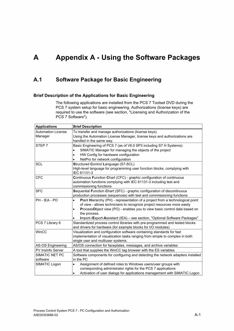
Process Control System PCS 7 - PC Configuration and Authorization A5E00353686-02 A-1
A Appendix A - Using the Software Packages
A.1 Software Package for Basic Engineering
Brief Description of the Applications for Basic Engineering The following applications are installed from the PCS 7 Toolset DVD during the PCS 7 system setup for basic engineering. Authorizations (license keys) are required to use the software (see section, "Licensing and Authorization of the PCS 7 Software").
Applications Brief Description Automation License Manager
To transfer and manage authorizations (license keys). Using the Automation License Manager, license keys and authorizations are handled in the same way.
STEP 7 Basic Engineering of PCS 7 (as of V6.0 SP3 including S7 H Systems): • SIMATIC Manager for managing the objects of the project • HW Config for hardware configuration • NetPro for network configuration
SCL Structured Control Language (S7-SCL) High-level language for programming user function blocks, complying with IEC 61131-3
CFC Continuous Function Chart (CFC) - graphic configuration of continuous automation functions complying with IEC 61131-3 including test and commissioning functions
SFC Sequential Function Chart (SFC) - graphic configuration of discontinuous production processes (sequences) with test and commissioning functions
PH - IEA - PO • Plant Hierarchy (PH) - representation of a project from a technological point of view - allows technicians to recognize project resources more easily
• ProcessObject view (PO) - enables you to view basic control data based on the process.
• Import-/Export-Assistant (IEA) – see section, "Optional Software Packages" PCS 7 Library 6 Standardized process control libraries with pre-programmed and tested blocks
and drivers for hardware (for example blocks for I/O modules) WinCC Visualization and configuration software containing standards for fast
implementation of visualization tasks ranging from simple to complex in both single user and multiuser systems.
AS-OS Engineering AS/OS connection for faceplates, messages, and archive variables PV InsInfo Server A tool that supplies the WinCC tag browser with the ES variables SIMATIC NET PC software
Software components for configuring and detecting the network adapters installed in the PC
SIMATIC Logon • Assignment of defined roles to Windows users/user groups with corresponding administrator rights for the PCS 7 applications
• Activation of user dialogs for applications management with SIMATIC Logon

Appendix A - Using the Software Packages
Process Control System PCS 7 - PC Configuration and Authorization A-2 A5E00353686-02
Applications Brief Description SIMATIC PDM Configuration, parameter assignment, commissioning, and diagnostics of
intelligent process devices. SIMATIC PDM allows a wide variety of process devices to be configured using a uniform user interface.
A.2 Software Packages for Operator Stations
Brief Description of the Applications for Operator Stations The following applications are installed from the PCS 7 Toolset DVD during the PCS 7 system setup for operator stations. License keys (authorizations) are required to use the software (see section, "Licensing and Authorization of the PCS 7 Software").
Program Name Brief Description
Automation License Manager
To transfer and manage authorizations (license keys). With the introduction of the Automation License Manager, license keys and authorizations are handled in the same way.
WinCC This is a visualization and configuration software for visualization in the single user or multiuser mode. To learn about the scale of authorization, refer to the section, "Licensing and Authorization of the PCS 7 Software".
SFC Visualization allows you to display and control sequential control systems. PCS 7 Faceplates contains standardized libraries with tested, ready-to-use blocks (connection to AS
and faceplates) @ PCS 7 with an @aGlance interface offers a basis for company-wide data exchange. SIMATIC NET PC software
Contains the software components for configuring and detecting the network adapters installed in the PC
SIMATIC Logon Service
The SIMATIC Logon Service activates the user dialogs for the applications managed with SIMATIC Logon and assigns users are specific permissions after successful logon. It supports the functions logon, logoff, change user and change password.
SIMATIC Logon Admin Tool
With the SIMATIC Logon Admin Tool, the roles defined for the applications can be assigned to Windows users/user groups. With suitable administrator permissions, Windows users and user groups can also be edited.
SIMATIC Electronic Signature
With SIMATIC Electronic Signature, operations can only be executed after they have been enabled by the previously assigned Windows users/user groups. The assignment of the users and user groups is made in the application.

Appendix A - Using the Software Packages
Process Control System PCS 7 - PC Configuration and Authorization A5E00353686-02 A-3
A.3 Software Packages for SIMATIC BATCH
Brief Description of the Applications for SIMATIC BATCH The following applications are installed from the PCS 7 Toolset DVD during the PCS 7 system setup for SIMATIC BATCH. License keys (authorizations) are required to use the software (see section, "Licensing and Authorization of the PCS 7 Software").
Program Name Brief Description Automation License Manager
To transfer and manage authorizations (license keys). With the introduction of the Automation License Manager, license keys and authorizations are handled in the same way.
BATCH Base Basis for all BATCH installations Includes the installation of the client database A license key for BATCH API is required to interface with a factory or enterprise-wide information system (see section, "Licensing and Authorization of the PCS 7 Software").
BATCH Builder Software package for installation on the PCS 7 ES for creation and configuration of BATCH project data • OM, • Builder
BATCH Client • BCC - he Batch Control Center (Batch CC) is the central component in SIMATIC BATCH for batch planning and control. Batch CC manages all data relating to SIMATIC BATCH. It therefore allows logging of all data in Batch CC.
• The BATCH Recipe Editor is responsible for the graphic creation and management of any number of recipes.
• BATCH REPORT - The user-friendly print function of BATCH BATCH Server • BCS - Sequential control system of BATCH and allocation of units
• BDM - Batch Data Management collects, stores, logs, and exports batch data.
• To learn about the scale of authorization, refer to the section, "Licensing and Authorization of the PCS 7 Software".
BATCH Fastobjects For installation of a database server. • POET Server • BATCH DBMON
BATCH Block BATCH interface blocks BATCH WinCC Option Faceplates for SIMATIC BATCH SIMATIC Logon Service
The SIMATIC Logon Service activates the user dialogs for the applications managed with SIMATIC Logon and assigns users are specific permissions after successful logon. It supports the functions logon, logoff, change user and change password.
SIMATIC Logon Admin Tool
With the SIMATIC Logon Admin Tool, the roles defined for the applications can be assigned to Windows users/user groups. With suitable administrator permissions, Windows users and user groups can also be edited.
SIMATIC Electronic Signature
With SIMATIC Electronic Signature, operations can only be executed after they have been enabled by the previously assigned Windows users/user groups. The assignment of the users and user groups is made in the application.
@ PCS 7 with an @aGlance interface offers a basis for company-wide data exchange.

Appendix A - Using the Software Packages
Process Control System PCS 7 - PC Configuration and Authorization A-4 A5E00353686-02
A.4 Optional Software Packages
The applications described below can be used for special engineering. You require additional license keys (authorizations) (see section, "Software Packages and Required Authorizations".
Add-ons in the Setup of PCS 7 You can install these programs directly in the PCS 7 system setup.
Applications Brief Description
PH - IEA - PO Import/Export Assistant (IEA) - tool for fast bulk engineering (for example importing models and process tags) Note: License for IEA necessary
DOCPRO Creating plant documentation and wiring manuals PLC simulation CPU simulation SFC visualization The SFC visualization option allows you to display and control sequential control
systems. Version Cross Checker
Comparison of engineering data versions with graphic display of differences
PCS 7 PID tuner Optimizing closed-loop controllers @ PCS 7 Installation of an @aGlance interface as the basis for company-wide data
exchange. PCS 7 Faceplates Faceplates for the operator station SIMATIC BATCH Automation of batch processes SIMATIC Route Control
Implementation of transport routes. Route Control engineering can be performed on a separate PC in multiproject engineering.
Add-ons on Their Own Installation Media These applications are not included on the PCS 7 Toolset DVD.
Applications Brief Description
S7 F Systems Used to configure fail-safe functions of a SIMATIC S7-400F/ SIMATIC S7-400FH - automatically adds functions for fault-detection and fault reactions to CFC charts created by the user, provides support functions, for example for synchronizing or acceptance tests for F programs.
Further Information You will find further information on the software packages and their areas of application in the brief description for Process Control System SIMATIC PCS 7 or in the Process Control System PCS 7; Catalog ST PCS7.

Process Control System PCS 7 - PC Configuration and Authorization A5E00353686-02 B-1
B Appendix B - Licensing the Software Package
B.1 Software Packages and Required Authorizations
The following table shows you which license keys (authorizations) you require for the respective software packages.
Note
The Windows 2000 Professional and Windows 2000 Server operating systems are not recommended for a new configuration of a PCS 7 network.
When PCS 7 networks are expanded, a mixed configuration is preferable for a network with "one" operating system (Windows 2000 or Windows XP/Windows Server 2003).
The central archive server has only been released for Windows Server 2003.
Notes on the Table ("Version" column)
The "Version" column is an empty column to allow you to enter the current data for documenting the plant. You will find the versions for the current program package "Process Control System PCS 7 Toolset V6.1" in the pcs7-readme file.
Note
In the following, we will only use the term license key even when an older authorization is used for a product.

Appendix B - Licensing the Software Package
Process Control System PCS 7 - PC Configuration and Authorization B-2 A5E00353686-02
Product Name
Vers
ion
License
Syst
em
Setu
p
Engineering Station
Single Station or Client for OS, BATCH or Route Control
All servers for OS, SIMATIC BATCH or Route Control redundant and non-redundant
Remarks X= necessary installation (X)= optional installation
Operating systems Not part of PCS 7 MS Windows XP Professional Microsoft license no X X With bundle hardware and software,
the product is supplied on separate CD.
Windows Server 2003 (server operating system)
Windows Server 2003 (normally 5 or 10 connection licenses included).
no For Multiproject Engineering
X With bundle hardware and software, the product is supplied on separate CD.
Operating system service pack no X X X Note about installing a server - Make sure you have an adequate number of licenses.
Product Name
Vers
ion
License
Syst
em
Setu
p
Engineering Station
Single Station or Client for OS, BATCH or Route Control
All servers for OS, BATCH or Route Control redundant and non-redundant
Remarks X= necessary installation (X)= optional installation
Operating systems (not recommended for new configurations) Not part of PCS 7 MS Windows 2000 Professional Microsoft license no X X With bundle hardware and software,
the product is supplied on separate CD.
MS Windows 2000 Server Microsoft Windows 2000 Server (normally 5 or 10 connection licenses included).
no For Multiproject Engineering
X With bundle hardware and software, the product is supplied on separate CD.
MS Windows 2000 Advanced Server
no Only for SIMATIC BATCH Server redundant (type: Microsoft Cluster)
Operating system service pack no X X X Note about installing the Windows 2000 Server - Make sure you have an adequate number of licenses.

Appendix B - Licensing the Software Package
Process Control System PCS 7 - PC Configuration and Authorization A5E00353686-02 B-3
Product Name
Vers
ion
License
Bas
ic S
etup
Engineering Station
Single Station or Client for OS, BATCH or Route Control
All servers for OS, SIMATIC BATCH or Route Control redundant and non-redundant
Remarks X= necessary installation (X)= optional installation
Miscellaneous MS SQL Server no X X X Internet Explorer no X X X Extra CD for use of OPC (V6.1) Adobe Acrobat Reader yes X (X) (X) PKZIP for Windows no X (X) (X) pcAnywhere without (host version) no (X) (X) (X) Automation License Manager yes X X X

Appendix B - Licensing the Software Package
Process Control System PCS 7 - PC Configuration and Authorization B-4 A5E00353686-02
ES Package OS Package Remarks
Product Name
Vers
ion
License Keys
Bas
ic
Setu
p ES
Sing
le
Stat
ion
OS
Sing
le
Stat
ion
OS
Serv
er
OS
Clie
nt X= necessary installation
(X)= optional installation
PCS 7 ES STEP 7 STEP 7 yes X X H systems are integrated SIK/SIMATIC H Systems Vx.y (X) (X) For H Systems (X) product is always installed when
STEP 7 is installed. CFC CFC (z) yes (z) (z) Limitation of number of process objects (PO =
operator controllable function block with attribute S7_m_c) - (z) scaling of the license keys - see section, Authorizations for the Engineering Station
SFC SFC yes X X SCL S7-SCL yes X X PH/IEA/PO TH-PO yes X X License key for using the IEA option necessary AS-OS Engineering yes (X) (X) (X) Product is always installed when STEP 7 and
WinCC are installed. PV InsInfo Server yes (X) (X) SFC Visualization SFC Visualization yes (X) (X) (X) (X) (X) (X) Product is always installed when WinCC is
installed. DOCPRO SIK/SIMATIC DOCPRO yes (X) (X) Version Cross Checker Version Cross Checker yes (X) (X) S7-PLC Simulation PLCSIM yes (X) (X) PCS 7 Library 61 yes X X PCS 7 Faceplates yes X X X X X PCS 7 PID Tuner SIK/SIMATIC PID Tuner yes (X) (X) Version Trail yes X X

Appendix B - Licensing the Software Package
Process Control System PCS 7 - PC Configuration and Authorization A5E00353686-02 B-5
ES Package OS Package Remarks
Product Name
Vers
ion
License Keys
Bas
ic
Setu
p ES
Sing
le
Stat
ion
OS
Sing
le
Stat
ion
OS
Serv
er
OS
Clie
nt X= necessary installation
(X)= optional installation
Optional Packages for all PCS 7 PCs SIMATIC Logon Service Logon Service yes (X) (X) (X) (X) (X) (X) All stations that use applications managed with
the SIMATIC Logon Service require the SIMATIC Logon Service.
SIMATIC Logon Admin Tool
Logon Admin Tool yes (X) (X) (X) (X) (X) (X) The SIMATIC Logon Admin Tool is required only once per plant - it must be installed on some station (server/client/single station).
SIMATIC Electronic Signature
Electronic Signature yes (X) (X) (X) (X) (X) (X) All stations that use applications protected by SIMATIC Electronic Signature require SIMATIC Electronic Signature.
ES Package OS Package Remarks
Product Name
Vers
ion
License Keys
Bas
ic
Setu
p ES
Sing
le
Stat
ion
OS
Sing
le
Stat
ion
OS
Serv
er
OS
Clie
nt X= necessary installation
(X)= optional installation
PCS 7 AS SIMATIC NET PC SW BCE yes X X X X License only for standard Ethernet interface module
(not necessary for SIMATIC NET CP 1613) S7 F Systems SIK/SIMATIC S7 F Systems V(x.x) no (X) (X) Product supplied on extra CD

Appendix B - Licensing the Software Package
Process Control System PCS 7 - PC Configuration and Authorization B-6 A5E00353686-02
ES Package OS Package Remarks Product Name
Vers
ion
License Keys
Bas
ic
Setu
p ES
Sing
le
Stat
ion
OS
Sing
le
Stat
ion
OS
Serv
er
OS
Clie
nt X= necessary installation
(X)= optional installation
SIMATIC PDM
SIMATIC PDM Basic Software
PDM BASIC – (up to 4 TAGs) The following TAG licenses are available as options: - PDM ("*z") *z = 128, 512, 1024, 2048, unlimited Number of TAGs (devices)
yes X X The SIMATIC PDM basic software V6.0 includes the following licenses: • Communication over HART modem, • Communication over RS-232, • Communication over PROFIBUS DP/PA, 4
TAGs For more detailed information, please refer to the information on the product SIMATIC PDM
PDM Integration in STEP7 yes (X) (X) Is required only when the integration of PDM in HW Config can be used.
PDM Routing yes (X) (X) Routing via S7-4xx PDM Hart Mux yes (X) (X) Communication via Standard HART Multiplexer
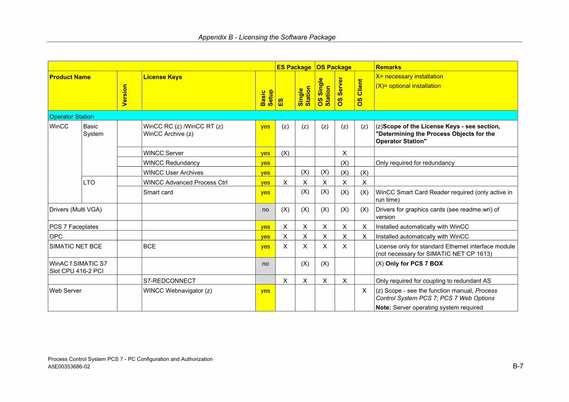
Appendix B - Licensing the Software Package
Process Control System PCS 7 - PC Configuration and Authorization A5E00353686-02 B-7
ES Package OS Package Remarks Product Name
Vers
ion
License Keys
Bas
ic
Setu
p ES
Sing
le
Stat
ion
OS
Sing
le
Stat
ion
OS
Serv
er
OS
Clie
nt X= necessary installation
(X)= optional installation
Operator Station
WinCC Basic System
WinCC RC (z) /WinCC RT (z) WinCC Archive (z)
yes (z) (z) (z) (z) (z) (z)Scope of the License Keys - see section, "Determining the Process Objects for the Operator Station"
WINCC Server yes (X) X WINCC Redundancy yes (X) Only required for redundancy WINCC User Archives yes (X) (X) (X) (X) LTO WINCC Advanced Process Ctrl yes X X X X X Smart card yes (X) (X) (X) (X) WinCC Smart Card Reader required (only active in
run time) Drivers (Multi VGA) no (X) (X) (X) (X) (X) Drivers for graphics cards (see readme.wri) of
version PCS 7 Faceplates yes X X X X X Installed automatically with WinCC OPC yes X X X X X Installed automatically with WinCC SIMATIC NET BCE BCE yes X X X X License only for standard Ethernet interface module
(not necessary for SIMATIC NET CP 1613) WinAC f SIMATIC S7 Slot CPU 416-2 PCI
no (X) (X) (X) Only for PCS 7 BOX
S7-REDCONNECT X X X X Only required for coupling to redundant AS Web Server WINCC Webnavigator (z) yes X (z) Scope - see the function manual, Process
Control System PCS 7; PCS 7 Web Options Note: Server operating system required

Appendix B - Licensing the Software Package
Process Control System PCS 7 - PC Configuration and Authorization B-8 A5E00353686-02
Product Name
Vers
ion
License Keys
Bas
ic
Setu
p
Central archive server Remarks X= recommended (X)= optional installation
Central Archiv Server WinCC yes X StoragePlus StoragePlus yes X StoragePlus WebViewer (x) also on any PC for
visualization of archive data Batch Report yes X
Product Name
Vers
ion
License Keys
Bas
ic S
etup
BA
TCH
Si
ngle
St
atio
n B
ATC
H
Serv
er
Red
unda
nt
BA
TCH
se
rver
s B
ATC
H
clie
nt
BA
TCH
En
gine
erin
g Remarks
SIMATIC BATCH
BATCH Base yes X X X X X Basic Installation for all SIMATIC BATCH PCs
BATCH Builder yes X X BATCH WinCCOption X X BATCH Block X X BATCH Server BATCH Server (z) yes (z) (z) (z) (z) Scope of the License Keys - see
section, "Determining the Process Objects for the BATCH Station"
BATCH API BATCH API X X X BATCH Fastobjects X X X License BATCH Separation Procedures/Formulas
BATCH Formula X X X
BATCH Hierarchical Recipe
BATCH Hierarchical Recipe X X X
BATCH ROP Lib 6.0 BATCH Library X X X BATCH Client - BCC BATCH BatchCC yes X X and/or BATCH Recipe System
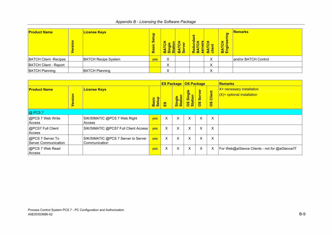
Appendix B - Licensing the Software Package
Process Control System PCS 7 - PC Configuration and Authorization A5E00353686-02 B-9
Product Name
Vers
ion
License Keys
Bas
ic S
etup
BA
TCH
Si
ngle
St
atio
n B
ATC
H
Serv
er
Red
unda
nt
BA
TCH
se
rver
s B
ATC
H
clie
nt
BA
TCH
En
gine
erin
g Remarks
BATCH Client -Recipes BATCH Recipe System yes X X and/or BATCH Control BATCH Client - Report X X BATCH Planning BATCH Planning X X
ES Package OS Package Remarks Product Name
Vers
ion
License Keys
Bas
ic
Setu
p
ES
Sing
le
Stat
ion
OS
Sing
le
Stat
ion
OS
Serv
er
OS
Clie
nt X= necessary installation
(X)= optional installation
@ PCS 7 @PCS 7 Web Write Access
SIK/SIMATIC @PCS 7 Web Right Access
yes X X X X X
@PCS7 Full Client Access
SIK/SIMATIC @PCS7 Full Client Access yes X X X X X
@PCS 7 Server To Server Communication
SIK/SIMATIC @PCS 7 Server to Server Communication
yes X X X X X
@PCS 7 Web Read Access
yes X X X X X For Web@aGlance Clients - not for @aGlance/IT

Appendix B - Licensing the Software Package
Process Control System PCS 7 - PC Configuration and Authorization B-10 A5E00353686-02
ES Package Route Control -
Package Remarks
Product Name
Vers
ion
License Keys
Bas
ic
Setu
p
ES
Sing
le
Stat
ion
Rou
te
Con
trol
-
Rou
te
Con
trol
-
Rou
te
Con
trol
-
X= necessary installation (X)= optional installation
ROUTE Control Route Control Basic yes X X X X X Route Control Engineering
Route Control Engineering yes X X Wizard in the context of the SIMATIC Manager, Library Blocks, Engineering Tool
Route Control Server Route Control Server (z) yes X X (redundant also) (z) Scope of the License Keys - see section, "Determining the Routes for the Route Control Station"
Faceplate for WinCC yes X X X X Route Control Center Route Control Center yes X X Route Control Library yes X X X Route Control Faceplate yes X X
Maintenance Station Remarks Product Name
Vers
ion
License Keys
Bas
ic
Setu
p
ES
Sing
le
Stat
ion
X= necessary installation (X)= optional installation
Maintenance Station Maintenance Station Asset RT (z) yes (z) (z) (z) License Key Levels Maintenance Station Engineering
Asset ES yes X X

Process Control System PCS 7 - PC Configuration and Authorization A5E00353686-02 C-1
C Appendix C - Approved Configurations on a PC Station
C.1 Approved Configurations
Introduction One PC station can be used for more than the standard configurations for PCS 7. By installing additional program packages or taking advantage of special properties, one PC station can be used for several purposes (such as an OS server and an operator station).
Standard Configurations The following program packages are offered for the installation of a PC station during the PCS 7 system setup:
• Engineering
- PCS 7 Engineering, BATCH Engineering, Route Control Engineering, PDM
or
• Runtime
- For a single station: OS Single Station or BATCH Single Station or Route Control Single Station
- For a server: OS Server or Central Archive Server or BATCH Server or Route Control Server
- For a client: OS Client or BATCH Client or Route Control Client or Maintenance Client
- For a Web Server: OS Web Server or OS Web Server including BATCH Faceplates
Notes about this section
Note In this section the activation of a standard configuration is referred to as the activation of an application, for example, the activation of process mode on a BATCH client.
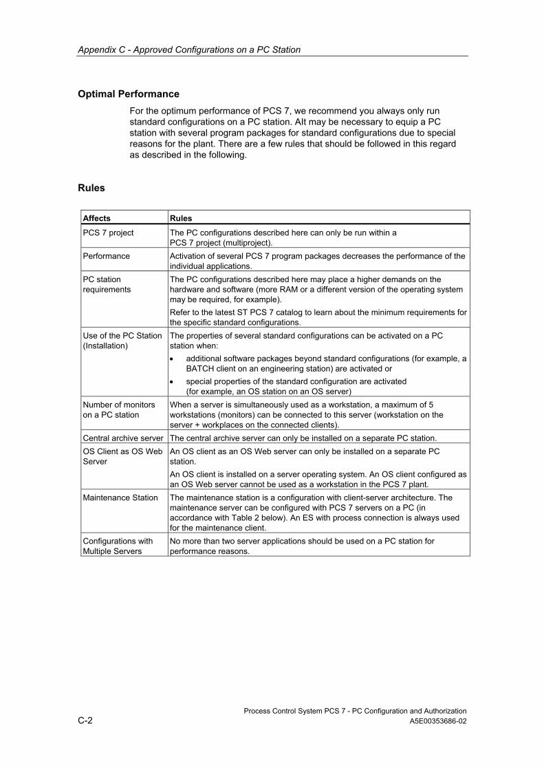
Appendix C - Approved Configurations on a PC Station
Process Control System PCS 7 - PC Configuration and Authorization C-2 A5E00353686-02
Optimal Performance For the optimum performance of PCS 7, we recommend you always only run standard configurations on a PC station. AIt may be necessary to equip a PC station with several program packages for standard configurations due to special reasons for the plant. There are a few rules that should be followed in this regard as described in the following.
Rules
Affects Rules
PCS 7 project The PC configurations described here can only be run within a PCS 7 project (multiproject).
Performance Activation of several PCS 7 program packages decreases the performance of the individual applications.
PC station requirements
The PC configurations described here may place a higher demands on the hardware and software (more RAM or a different version of the operating system may be required, for example). Refer to the latest ST PCS 7 catalog to learn about the minimum requirements for the specific standard configurations.
Use of the PC Station (Installation)
The properties of several standard configurations can be activated on a PC station when: • additional software packages beyond standard configurations (for example, a
BATCH client on an engineering station) are activated or • special properties of the standard configuration are activated
(for example, an OS station on an OS server) Number of monitors on a PC station
When a server is simultaneously used as a workstation, a maximum of 5 workstations (monitors) can be connected to this server (workstation on the server + workplaces on the connected clients).
Central archive server The central archive server can only be installed on a separate PC station. OS Client as OS Web Server
An OS client as an OS Web server can only be installed on a separate PC station. An OS client is installed on a server operating system. An OS client configured as an OS Web server cannot be used as a workstation in the PCS 7 plant.
Maintenance Station The maintenance station is a configuration with client-server architecture. The maintenance server can be configured with PCS 7 servers on a PC (in accordance with Table 2 below). An ES with process connection is always used for the maintenance client.
Configurations with Multiple Servers
No more than two server applications should be used on a PC station for performance reasons.

Appendix C - Approved Configurations on a PC Station
Process Control System PCS 7 - PC Configuration and Authorization A5E00353686-02 C-3
Approved Configurations - PC Station for Several PCS 7 Applications The following table lists the approved configurations for PC stations using several PCS 7 applications. The following figure shows the assignment of the configurations to the operating systems:
Notes about the table
Note
Tables 1 to 3 should be basically read from left to right. This means that a PC with a standard installation can be used for an additional application (by activating properties or by installing additional packages during the system setup of PCS 7).
Example: If y PC station with the "Engineering Station" standard configuration is also used as an "OS Single Station", the notes and restrictions listed under "A" in the legend are applicable (the legend is located at the end of this section).
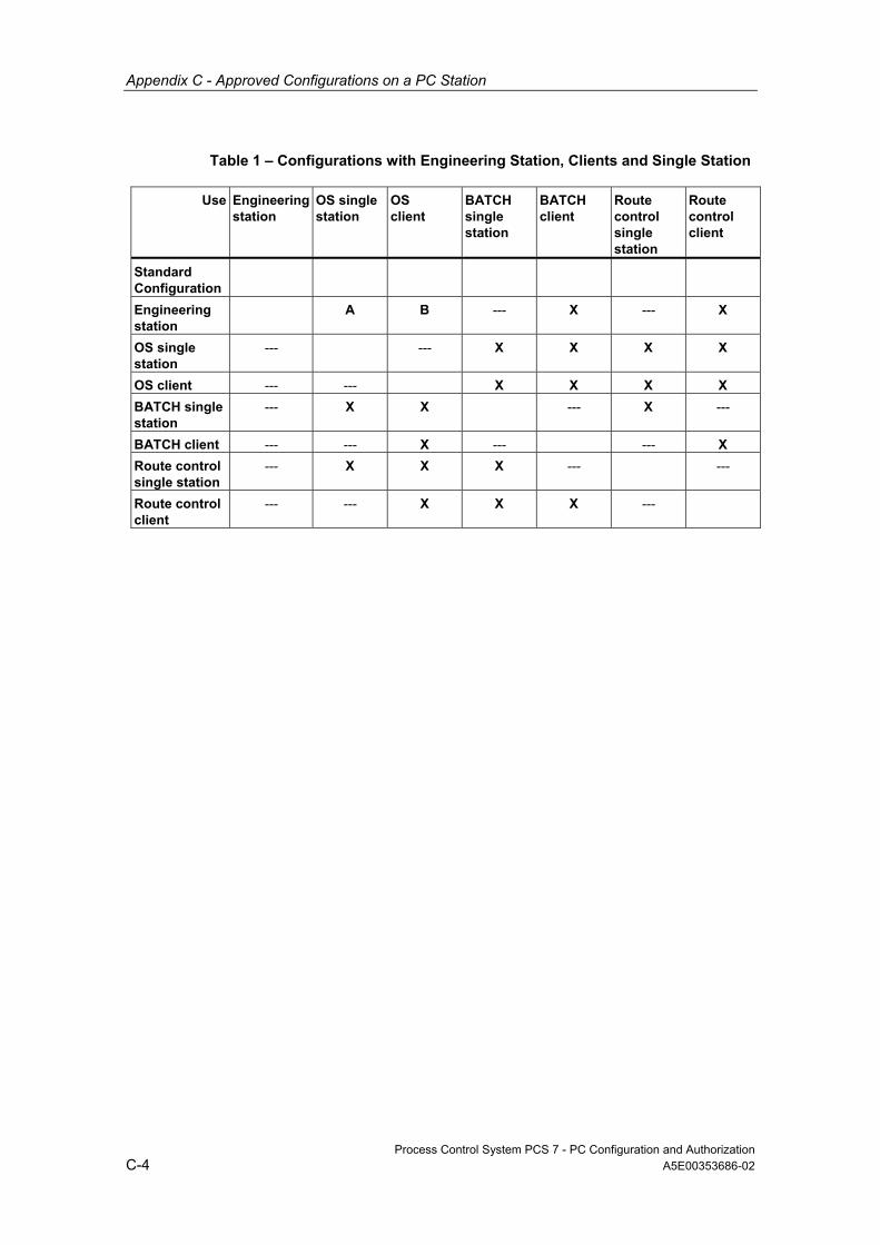
Appendix C - Approved Configurations on a PC Station
Process Control System PCS 7 - PC Configuration and Authorization C-4 A5E00353686-02
Table 1 – Configurations with Engineering Station, Clients and Single Station
Use Engineering station
OS single station
OS client
BATCH single station
BATCH client
Route control single station
Route control client
Standard Configuration
Engineering station
A B --- X --- X
OS single station
--- --- X X X X
OS client --- --- X X X X BATCH single station
--- X X --- X ---
BATCH client --- --- X --- --- X Route control single station
--- X X X --- ---
Route control client
--- --- X X X ---
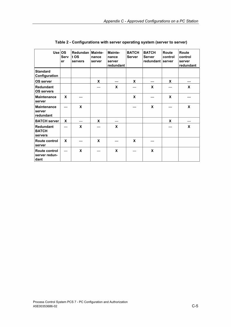
Appendix C - Approved Configurations on a PC Station
Process Control System PCS 7 - PC Configuration and Authorization A5E00353686-02 C-5
Table 2 - Configurations with server operating system (server to server)
Use OS Server
Redundant OS servers
Mainte-nance server
Mainte- nance server redundant
BATCHServer
BATCH Server redundant
Route control server
Route control server redundant
Standard Configuration
OS server X --- X --- X --- Redundant OS servers
--- X --- X --- X
Maintenance server
X --- X --- X ---
Maintenance server redundant
--- X --- X --- X
BATCH server X --- X --- X --- Redundant BATCH servers
--- X --- X --- X
Route control server
X --- X --- X ---
Route control server redun- dant
--- X --- X --- X

Appendix C - Approved Configurations on a PC Station
Process Control System PCS 7 - PC Configuration and Authorization C-6 A5E00353686-02
Table 3 - Configurations with server operating system (client installation on server)
Use Engineering station
OS single station
OS client
BATCH single station
BATCH client
Route control single station
Route control client
Standard Configuration
OS server --- --- X X X X X Redundant OS servers
--- --- X --- X --- X
Maintenance server
--- --- X X X X X
Maintenance server redundant
--- --- X --- X --- X
BATCH server --- X X --- X X X Redundant BATCH servers
--- --- X --- X --- X
Route control server
--- X X X X --- X
Route control server redun- dant
--- --- X --- X --- X

Appendix C - Approved Configurations on a PC Station
Process Control System PCS 7 - PC Configuration and Authorization A5E00353686-02 C-7
Captions of the Table
X
- No restrictions - read the configuration notes for the respective standard configurations.
---
- This configuration is not approved.
A
- If process mode of an OS is activated on the ES, simultaneous OS engineering can only be performed for this activated OS.
B
- No additional installation of an OS client is necessary since the OS workstation is already included in the standard configuration, "Engineering Station" .
- Only one PCS 7 application on a PC station can be active during OS configuration (engineering station or OS workstation - no simultaneous operation possible). The OS workstation cannot be used during AS configuration.
Note about configuration:
- A stand-alone OS client must be configured within the project in the SIMATIC Manager for this OS workstation.
- The OS client project is not downloaded (not required and not possible).
Note about process mode:
- The SIMATIC Manager has to be closed when opening the client project. If it is not, the OS client reads the server data from the engineering station!
- Activate the OS client: open WinCC Explorer > select OS client project > start process mode
Example Configuration: Example configuration for a redundant small plant with five workstations:
• 1 PC = 1 Engineering station = 1 workstation
• + 2 PCs = 1 OS server redundant = 2 workstations
• + 2 PCs = 1 BATCH server redundant = 2 workstations
Note
• Each workstation can be operated as an OS client and/or BATCH client.
• Restrictions: See legend for table above.

Appendix C - Approved Configurations on a PC Station
Process Control System PCS 7 - PC Configuration and Authorization C-8 A5E00353686-02

Process Control System PCS 7 - PC Configuration and Authorization A5E00353686-02 Index-1
Index
A Access to the PCS 7 OS over
Web Client 1-21 Additional drivers for PCS 7 3-43 After installing the operating system 3-10 Approved configurations C-1 Archive server 1-20, 3-18
additional components 3-18 central 1-20
Authorizations 3-47, 3-53, 3-54, 3-57 PCS 7 ES 3-53 PCS 7 OS 3-54 SIMATIC BATCH 3-57 software B-1
Authorizations for Route Control 3-58 Authorizations for the PCS 7 maintenance
station 3-56
B Basic configuration of the PCS 7 plant 1-1 Basic hardware for PCS 7 PCs 2-1 BATCH A-3
software A-3 BATCH multiple station system 1-16
C Central archive server 1-20 Commissioning 3-23
setting the color scheme 3-23 Setting the font size 3-23
Commissioning Wizard 3-61 Configuration Console 3-62
Communication routes between PC stations 3-61
Configuration Console 3-61 Configuring and Ordering 2-6 Connection paths between AS
OS BATCH
RCS and ES components 1-25 Connection to terminal/plant bus 1-26 Creating a backup 3-22
D Data exchange 3-65 Defragmenters 3-67 Different work methods with engineering
stations 1-6 Downloading the network configuration
to the PC stations 3-64 Drivers for communication modules 3-33
F Firewall 3-67
H Hard disk partitioning 3-2 Hardware 3-1
PC 3-1 How are single station system configured?
1-14 How many process objects can be handled
in a project? 3-51 How to activate a DCF77 module 3-46 How to activate a Multi-VGA graphics card
3-43 How to activate a sound card 3-45 How to Activate Redundancy for Redundant
OS/BATCH Servers 3-37 How to configure additional components
for the central archive server and StoragePlus 3-20
How to disable the power saving options of network cards 3-36
How to enable redundancy for fault-tolerant PCs 3-31
How to install the central archive server StoragePlus 3-29
How to install the driver for the redundant terminal bus 3-38
How to install Windows 2000 Professional and Server 3-7
How to make the settings for standard network adapters 3-64
How to prepare a maintenance station with CP1613 for monitoring the plant bus 3-41
How to select the communication module 3-63

Index
Process Control System PCS 7 - PC Configuration and Authorization Index-2 A5E00353686-02
How to set the language for a user MUI 3-19
How to Transfer License Keys 3-49
I Installation 3-1, 3-2, 3-5, 3-6, 3-10, 3-12,
3-13, 3-14, 3-15, 3-16, 3-17, 3-24, 3-25, 3-59 after installing the operating system 3-10 hard disk partitioning 3-2 Internet Explorer 3-12 message queuing service 3-13 MS SQL server 3-17 operating system 3-5 PC 3-1 PCS 7 3-24, 3-25 PCS 7 BOX 3-59, 3-60 software 3-2
Installation of PCS 7 package_XE Installation of PCS 7 package _ from the network 3-26
Installing a service pack 3-9 Internet Explorer 3-12
installing 3-12
L License 3-47, 3-48 License key B-1, 3-47, 3-48
Software B-1 Licensing 3-47 Licensing and authorization of the PCS 7
packages 3-47 Long-term archiving 1-20
M Maintenance multiple station system 1-18 Message queuing service 3-13, 3-14, 3-15,
3-16 MS SQL server 3-17
N Network interface for PCS 7 PC via
Industrial Ethernet 2-4 New Installation of the
PCS 7 Software 3-26 Note on installing 3-3
operating system 3-3, 3-4 Notes on installing 3-59
PCS 7 BOX 3-59 Notes on use 3-66, 3-67
of a virus scanner 3-66 of defragmenters 3-67
O Operating system 3-3, 3-5, 3-10
after installation of 3-10 note on installing 3-3
Operator stations A-2 Software A-2
Optional Hardware Components 2-5 Optional software A-4 OS A-2, 1-22, 3-54, 3-55, 3-56
authorizations 3-54 single station 1-22 software A-2
OS multiple station system 1-14
P PC configurations 1-24
PCS 7 BOX 1-24 PC station C-1, C-2, C-3, C-7
Approved configurations C-3 PCS 7 1-12, 1-13, 3-24
installation 3-24 PCS 7 BOX 1-12
PCS 7 applications and how they are used A-1
PCS 7 BOX 1-12, 1-24 PC configurations 1-24
PCS 7 ES 1-11, 3-53 authorizations 3-53 for a small system 1-11 Single station 1-11
Plant bus 3-34 installing modules 3-34
Preconfigured systems for PCS 7 bundles 2-3
Preface iii
R Reinstallation/Updating 3-32 Removing PCS 7 3-32 Route control - multiple station system
1-17 Route control single station 1-24
S Screen savers 3-65, 3-67 Setting the color scheme 3-23 Setting the font size 3-23 Setting up Users 3-21 Settings for BCE and Softnet CPs 3-35 SIMATIC BATCH A-3, 1-23, 3-57
authorizations 3-57 single station 1-23 software A-3

Index
Process Control System PCS 7 - PC Configuration and Authorization A5E00353686-02 Index-3
Single station 1-11, 1-22, 1-23 OS 1-22 PCS 7 ES 1-11 SIMATIC BATCH 1-23
Software A-2, A-3, A-4, B-1, 3-1, 3-24 authorizations B-1 ES optional A-4 Packages for operator stations A-2 packages for SIMATIC BATCH A-3 PC 3-1 PCS 7 installation 3-24
Software packages and required authorizations B-1
StoragePlus 1-20 Synchronizing the time 1-27
in a PCS 7 project 1-27
T Time synchronization 1-27
U Using several engineering stations for
PCS 7 project engineering 1-9 Using single of several PCs for a purpose
1-7 Using single PCs for PCS 7 project
engineering 1-10
V Virus scanner 3-66
W When should I use a fault-tolerant
redundant configuration? 1-4

Index
Process Control System PCS 7 - PC Configuration and Authorization Index-4 A5E00353686-02