System Integration of CubeSats - UNOOSA
55
KiboCUBE Academy System Integration of CubeSats Tohoku University Department of Aerospace Engineering Associate Professor Dr. –Ing. Toshinori Kuwahara Live Session #1-2 This lecture is NOT specifically about KiboCUBE and covers GENERAL engineering topics of space development and utilization for CubeSats. The specific information and requirements for applying to KiboCUBE can be found at: https://www.unoosa.org/oosa/en/ourwork/psa/hsti/kibocube.html
-
Upload
khangminh22 -
Category
Documents
-
view
4 -
download
0
Transcript of System Integration of CubeSats - UNOOSA

KiboCUBE Academy
System Integration of CubeSatsTohoku University
Department of Aerospace Engineering
Associate Professor Dr. –Ing. Toshinori Kuwahara
Live Session #1-2
This lecture is NOT specifically about KiboCUBE and covers GENERAL engineering topics of space development and utilization for CubeSats.
The specific information and requirements for applying to KiboCUBE can be found at: https://www.unoosa.org/oosa/en/ourwork/psa/hsti/kibocube.html

1. Introduction to CubeSat System Engineering
2. CubeSat Standards
3. CubeSat System Interface
4. CubeSat System Integration
5. CubeSat Functional Verification
6. CubeSat Project Management
7. Conclusion
Contents
November 4, 2021 KiboCUBE Academy 2

1. Introduction to CubeSat System Engineering
November 4, 2021 KiboCUBE Academy 3

There are a wide range of applications for CubeSats.
Earth Observation Optical observation
SAR (Synthetic Aperture Radar)
Radio signal analysis
Weather observation measurement
Communication Data relay
M2M (Machine-to-Machine) communication
AIS (Automatic Identification System)
High-speed laser communication
New technologies GNSS signal occultation measurement
Space robotics
Electrodynamic Tether
Re-entry and return capsule
Science Astronomy
Bioscience experiment
Moon, Asteroids, Planets, and Deep Space Exploration.
1. Introduction to CubeSat System Engineering1.1. Advanced Applications of CubeSats
EQUULEUS © JAXA
© NASA/JPL-Caltech
© JAXA/The University of Tokyo
© NASA/JPL-Caltech
© NASA/JPL-Caltech
© NASA/JPL-Caltech© Tohoku University
November 4, 2021 KiboCUBE Academy 4

1. Introduction to CubeSat System Engineering1.2. System Engineering Process
CubeSat Mission Initiation
Launch and Operation!
Mission Analysis and Design
System Analysis and Design
Preliminary Design
Detailed Design
Satellite Manufacturing
Mission Definition Review (MDR)
System Definition Review (SDR)
Preliminary Design Review (PDR)
Critical Design Review (CDR)
Launch Readiness Review (LRR)
System Definition
Development of Breadboard Model (BBM)
Development and Verification of Engineering Model (EM)
Manufacturing and Testing of Flight Model (FM)
Output
Requirements
Definition
Verification
Mission Definition
Qualification Review (QR)
November 4, 2021 KiboCUBE Academy 5

Input: Mission Objectives
Output: Mission Requirements
Functional Requirements
Operational Requirements
Constraints
Mission Constraints:
Launch Opportunities
(Mass properties, Size, Launch Environment, Orbit, etc.)
Schedule
Cost
Human Resources
Development Facilities
Interfaces
Regulations
Space Environment
1. Introduction to CubeSat System Engineering1.3. Mission Analysis and Design
Satellite Launch Vehicle
Ground Station
Ground Support Equipment
Test Facilities
November 4, 2021 KiboCUBE Academy 6

Input: Mission Requirements
Output: System Definition
Preliminary Mission Concept
Satellite Orbit, Number of Satellites
Payload Instruments
Satellite Bus System
Launch Vehicle Selection
Operation Planning
Ground Station
Ground Support Equipment
1. Introduction to CubeSat System Engineering1.4. System Analysis and Design
Payload Instruments
Types of Instruments
Communication
Optical Observation
Mass
Size
Power Consumption
Voltage
Telemetry Data
Mission Data
Command Data
Thermal Control
Pointing Accuracy
Operational Constraints
Bus System
Mass
Size
Power Consumption, Generation
Attitude Control
Telemetry Data
Command Data
Computational Capability
Communication Capability
Thermal Control Capability
Orbit Control
Propulsion
Autonomy
November 4, 2021 KiboCUBE Academy 7

A satellite system consists of several subsystems. Typical categorization is as follows:
1. Introduction to CubeSat System Engineering1.5. Satellite Subsystems
Power Control System
Communication System
Command and Data Handling System
Structure and Mechanism SystemThermal Control System
Attitude Control System
Orbit Control System(Advanced)
PayloadSystem
+ Harness System
November 4, 2021 KiboCUBE Academy 8

Iterative design refinement and verification process
Satellite system sizing and budget control through trade-offs
Mass Budget (Mass Property)
Power Budget (Power consumption, generation, and storage)
Size Budget
Communication Budget
Data Storage Budget
Computational Budget
Operation Time Budget
Financial Budget
Schedule Budget
Satellite system design is an art!
1. Introduction to CubeSat System Engineering1.6. Satellite System Design
Preliminary Design
FM
EM
BBM
Verification & Flight!
November 4, 2021 KiboCUBE Academy 9
Detailed Design, verification, and Qualification
PDR
CDR

2. CubeSat Standards
November 4, 2021 KiboCUBE Academy 10

KiboCUBE Academy 11
Some standards are available:
CubeSat Design Specification rev.13 (2014/2/20)6U CubeSat Design Specification rev. 1.0 (2018/6/7)- California Polytechnic State University(https://www.cubesat.org/)
CubeSat Subsystem Interface Definition version 1.0- UNISEC Europe (2017/8/24)(http://unisec-europe.eu/wordpress/wp-content/uploads/CubeSat-Subsystem-Interface-Standard-V2.0.pdf)
ISO Space systems – Cube satellites (CubeSats)(https://www.iso.org/standard/60496.html )
JEM* Payload Accommodation Handbook Vol.8 D- JAXA (* Japanese Experiment Module (JEM) = Kibo)(https://iss.jaxa.jp/kibouser/provide/j-ssod/#sw-library)English (2020/7/31)(https://humans-in-space.jaxa.jp/kibouser/library/item/jx-espc_8d-d1_en.pdf )Japanese (2020/5/25) (https://humans-in-space.jaxa.jp/kibouser/library/item/jx-espc_8d-d1.pdf )
2. CubeSat Standard2.1. CubeSat Standardization History
© University of Tokyo
11
3.5
mm
100 mm
10
0 m
m
November 4, 2021
1 Unit: 10 cm cube, 1.33kg
Refence Document: JAXA Common Technical Documentation (https://sma.jaxa.jp/en/TechDoc/index.html )

“KiboCUBE” provides deployment opportunities from the ISS Kibo module.
The possible launch vehicle can be one of the transfer vehicles to the ISS: HTV: H-II Transfer Vehicle
SpX Dragon: SpaceX Dragon
Orbital Cygnus
The launch environment is different in each vehicle.
CubeSats are installed in the satellite deployment POD (J-SSOD: Japanese Experiment Module (JEM) Small Satellite Orbital Deployer) and stowed inside the Cargo Transfer Bag (CTB) with soft packing material.
Vibration conditions are very mild relative to those encountered during a direct launch.
Frequent launch opportunities are provided, up to 4 times per year.
Adopting an approximate orbital altitude of 400 km ensures the CubeSats re-enter the atmosphere after their mission lifetime without becoming space debris.
2. CubeSat Standard2.2. KiboCUBE Launch Opportunity
Deployment from the ISS © JAXACubeSat Transfer to the ISS © JAXA
November 4, 2021 KiboCUBE Academy 12

2. CubeSat Standard2.3. Kibo Release Opportunities
Reference: JEM Payload Accommodation Handbook Vol. 8 Dhttps://iss.jaxa.jp/kibouser/library/item/jx-espc_8d.pdf
November 4, 2021 KiboCUBE Academy 13

CubeSats are installed in launch and release “pods.”
There are several different types of CubeSats, listed below:
1U: 1 x 1 x 1 Unit
1.5U: 1 x 1 x 1 Unit
2U: 1 x 1 x 2 Units
3U: 1 x 1 x 3 Units
4U: 1 x 1 x 4 Units
5U: 1 x 1 x 5 Units
6U-long: 1 x 1 x 6 Units
6U-wide: 1 x 2 x 3 Units
etc.
2. CubeSat Standard2.4. Types of CubeSats
© AAC Clyde Space
Types of Pods:
3U: 1 x 1 x 3 Unit
6U-wide: 1 x 2 x 3 Units
6U-long: 1 x 1 x 6 Units
etc.
3U CubeSat
© JAXA
© JAXA
November 4, 2021 KiboCUBE Academy 14

Standardization of CubeSat specification can expedite world-wide application of CubeSats.
CubeSat subsystem interface standards suggested by UNISEC-Europe defines the interface specifications of the electrical interfaces based on the experiences of UWE projects, with the goal to promote a generic satellite platform.
The design has been optimized with respect to mass, size, and energy efficiency, while trying to maintain a modular and flexible architecture.
The proposed bus supports robust and rapid development, integration and testing of the satellite as well as simple maintenance, extension, and replacement of subsystems.
2. CubeSat Standard2.5. CubeSat Subsystem Interface Definition – UNISEC-Europe
Figure: Overview of the modular UWE-3 pico-satellite bus being optimized for rapid integration and testing. Acts as a first reference implementation of the UNISEC bus.
CubeSat Subsystem Interface Definition version 1.0http://unisec-europe.eu/wordpress/wp-content/uploads/CubeSat-Subsystem-Interface-Standard-V2.0.pdf
November 4, 2021 KiboCUBE Academy 15

3. CubeSat System Interface
November 4, 2021 KiboCUBE Academy 16
A system with n components has 𝑛(𝑛−1)
2interfaces in between.
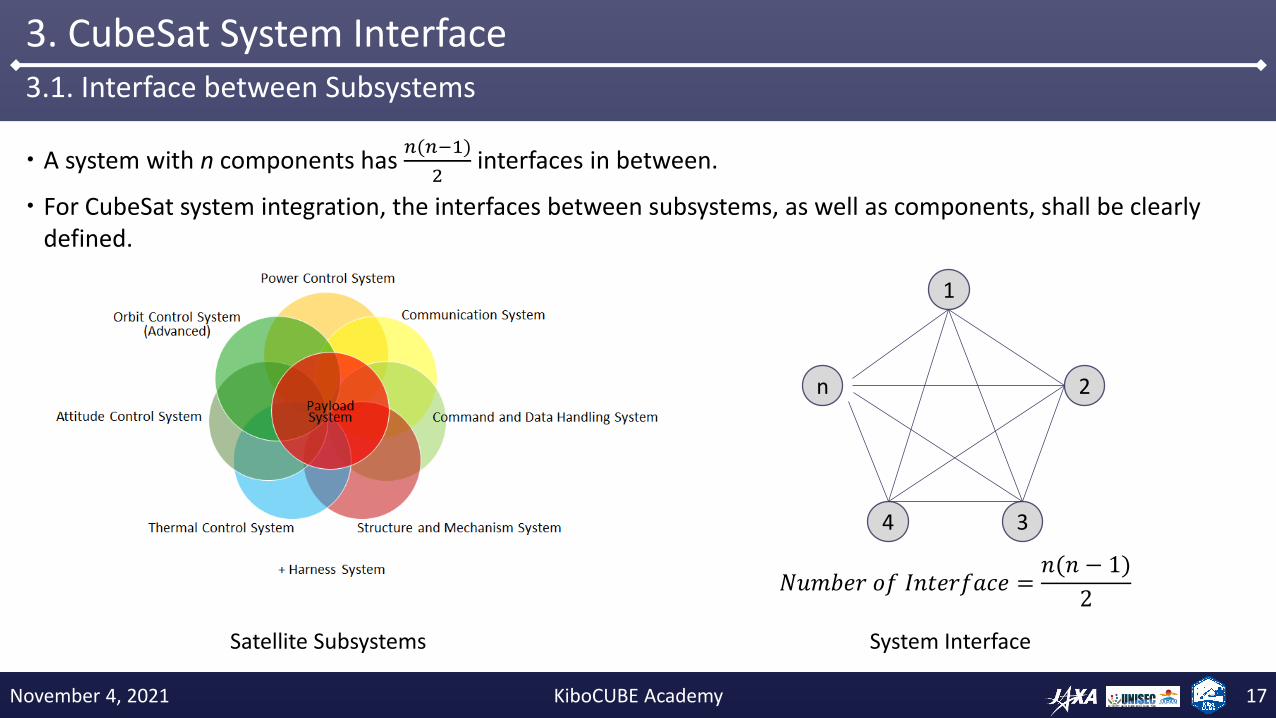
For CubeSat system integration, the interfaces between subsystems, as well as components, shall be clearly defined.
3. CubeSat System Interface3.1. Interface between Subsystems
Satellite Subsystems
1
System Interface
2
34
n
𝑁𝑢𝑚𝑏𝑒𝑟 𝑜𝑓 𝐼𝑛𝑡𝑒𝑟𝑓𝑎𝑐𝑒 =𝑛(𝑛 − 1)
2
November 4, 2021 KiboCUBE Academy 17

System architecture can be described using a system block diagram. Satellite components can be generally categorized into subsystems according to their functionalities.
Each interface needs to be specified, controlled, integrated, and tested for the system integration.
3. CubeSat System Interface3.2. Satellite System Block Diagram
TX(Low-Speed)
SatelliteMain Computer(s)
Power control SystemComputer
Battery
Solar Cell Panels
Communication System Command & Data Handling Attitude Control System
Power Supply System
Main computing unit
Sensors
Attitude (&Orbit)Control System
Computer
Payload SystemComputer
RX
Payload Cameras
Payload Sensors
Magnetometers
Ground Station
TX(High-Speed)
Sun Sensors
Star Sensors
Gyroscopes
Earth Sensors
GPS
MagneticTorquers
ReactionWheels
Thrusters
Actuators
GPS
Payload System
Magnetometers
MagneticTorquers
Sun Sensors
November 4, 2021 KiboCUBE Academy 18

3. CubeSat System Interface3.3. Satellite System Computers
Power Control Computer Attitude Control ComputerMain Computer
Payload Control Computer
Example of On-board Computers (Micro-satellite RISESAT)
© Tohoku University© ALE
November 4, 2021 KiboCUBE Academy 19

Satellite system architecture reflects the complexity of the system, and depends on the mission objectives and requirements.
Fulfilling the mission requirements with minimum component configuration is important to achieve a high system reliability.
3. CubeSat System Interface3.4. Electrical Configuration Design
TX(Low-Speed)
SatelliteMain Computer
Power control SystemComputer
Battery
Solar Cell Panels
RX
Payload Cameras
SatelliteMain Computer
BatteryDeploymentMechanism
GPS
Magnetometers
MagneticTorquers
Sun Sensors
Implementation example of 1U CubeSat FREEDOM CubeSat system with payload camera and coarse attitude control system
© Tohoku University© Tohoku University
November 4, 2021 KiboCUBE Academy 20

Types of electrical interface can be classified as follows:
Power supply interface
Unregulated/Bus: Satellite bus voltage, which fluctuates depending on the state of charge (SOC) of the battery.
Regulated: Voltages-regulated power supply through DC/DC converters, such as 3.3V, 5V, 12, 28V, etc.
Signal interface
Analog signal
Active analog: voltage output from analog sensors, voltage output from powered devices.
Passive analog: thermistors (power is supplied from outside to measure the value)
Digital signal
Discrete signal: ON/OFF status of mechanical switches, status of electrical circuits, etc.
Synchronous Serial: Communication interface with dedicated clock signals, suitable for high-speed communication.
Asynchronous Serial: Communication interface without dedicated clock signals, suitable for low-speed communication with less cables.
Radio Frequency
Communication between satellite and ground station. Require international radio frequency coordination (before launch), and license.
Communication between satellites, between components inside a satellite, etc.
3. CubeSat System Interface3.5. Electrical Interface
DC/DCConverter
ComponentBus RegulatedPower
ControlSystem
November 4, 2021 KiboCUBE Academy 21

Power distribution from the power control system to satellite components can be direct or in-direct, mainly depending on the configuration of the mechanical integration of the satellite electrical components.
Harness system becomes simpler when the power supply lines and signal lines can be combined into a harness assembly between two devices.
For a relatively bigger satellite system, hub configuration becomes more efficient.
The voltage of unregulated power supply lines is usually higher than the regulated voltage, and hence, more efficient in power distribution over a long harness.
Attention needs to be paid that a long harness causes a considerable voltage drop, and also that a high current flow generates noticeable magnetic fields which causes disturbance to the satellite attitude stability.
3. CubeSat System Interface3.6. Power Distribution Method
Solar Cells
Power Control System
Battery
Satellite Component
Point-to-Point Star Configuration
Satellite Component
Satellite Component
Hub Configuration
Solar Cells
Power Control
Unit
Battery
Satellite Component
Satellite Component
Satellite Component
November 4, 2021 KiboCUBE Academy 22

Power distribution architecture shall be carefully designed especially for small space systems in order to reduce the system complexity, number of components, harness, mass, size, volume, and power inefficiency.
3. CubeSat System Interface3.7. Power Distribution Architecture
TX(Low-Speed)
SatelliteMain Computer(s)
Power control SystemComputer
Battery
Solar Cell Panels
Communication System Command & Data Handling Attitude Control System
Power Supply System
Main computing unit
Sensors
Attitude (&Orbit)Control System
Computer
Payload SystemComputer
RX
Payload Cameras
Payload Sensors
Magnetometers
Ground Station
TX(High-Speed)
Sun Sensors
Star Sensors
Gyroscopes
Earth Sensors
GPS
MagneticTorquers
ReactionWheels
Thrusters
Actuators
GPS
Payload System
Magnetometers
MagneticTorquers
Sun Sensors
November 4, 2021 KiboCUBE Academy 23
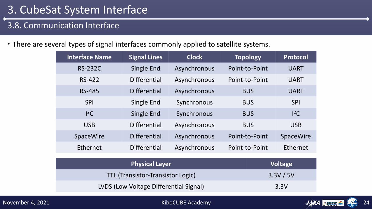
There are several types of signal interfaces commonly applied to satellite systems.
3. CubeSat System Interface3.8. Communication Interface
Interface Name Signal Lines Clock Topology Protocol
RS-232C Single End Asynchronous Point-to-Point UART
RS-422 Differential Asynchronous Point-to-Point UART
RS-485 Differential Asynchronous BUS UART
SPI Single End Synchronous BUS SPI
I2C Single End Synchronous BUS I2C
USB Differential Asynchronous BUS USB
SpaceWire Differential Asynchronous Point-to-Point SpaceWire
Ethernet Differential Asynchronous Point-to-Point Ethernet
Physical Layer Voltage
TTL (Transistor-Transistor Logic) 3.3V / 5V
LVDS (Low Voltage Differential Signal) 3.3V
November 4, 2021 KiboCUBE Academy 24

The computer network architecture shall be carefully designed for developing a computer system for satellites.
There are several different computer network architectures as below:
3. CubeSat System Interface3.9. Computer Network Architecture
Main Computer
Architecture Centralized (Star) Architecture Ring Architecture Bus Architecture
MeritsHigh integrity, direct interface only
Less influence of unit failureSmaller wiring harnessEasy to add new node
Smaller wiring harnessEasy to add new node
DemeritsPoint-to-Point connection
Large wiring harnessMore influence of unit failure
Low communication throughput Interface needs to be compatibleLow communication throughput
PeripheralComputer
Sensors
PeripheralComputer
Actuators
PeripheralComputer
Payloads
Centralized (Star) Architecture
DistributedComputer
Sensors
DistributedComputer
Actuators
DistributedComputer
Payloads
Ring Architecture
Payloads
Bus Architecture
Main/Distributed Computer
PeripheralComputer
PeripheralComputer
SensorsActuators
November 4, 2021 KiboCUBE Academy 25

Radio Frequency interface needs a special point-to-point harness connection.
RF connectors are relatively big and RF cables are relatively thick due to the shielding materials.
Point-to-Point connection requires harness wiring, which consumes space inside the satellite, and mass budget.
Harness wiring needs special attention for the accessibility and integration procedure.
3. CubeSat System Interface3.10. Radio Frequency interface
2U CubeSat RAIKO © Tohoku University1U CubeSat © Kyutech
RF Cable
November 4, 2021 KiboCUBE Academy 26

Three major ways of mechanical and electrical integration: PC-104 Style, Backplane Style, and Point-to-Point.
The scope of the standards include mechanical interfaces, connectors, types of signals, and pin assignments.
3. CubeSat System Interface3.11. Mechanical and Electrical Interface Standardization
PC-104 Style Backplane Style
© AAC Clyde Space © Kyutech
Point-to-Pont
© AAC Clyde Space
November 4, 2021 KiboCUBE Academy 27

Payload instruments usually tend to have custom interfaces with a combination of different types of electrical interfaces.
Due to the limitation of mechanical envelope and maintainability, payload instruments need to be assembled as a unit by defining the mechanical, electrical, and thermal interfaces very clearly.
Payload instruments related with radio frequency measurements are equipped with large antennas, which needs to be held down during the launch and deployed in orbit.
3. CubeSat System Interface3.12. Payload Interface
Payload Section
Bus System Section
3U CubeSat S-CUBE © Chiba Institute of Technology / Tohoku University
10 cm
November 4, 2021 KiboCUBE Academy 28

4. CubeSat System Integration
November 4, 2021 KiboCUBE Academy 29

Thanks to worldwide CubeSat interface standardization efforts, the mechanical and electrical systems of CubeSats can be integrated in a very dense manner to a limited mechanical envelope.
System design and integration shall be planned in the way that the resources for the payload can be maximized, especially such as the mass, envelope, and power.
CubeSats need to be assembled to fulfil the tolerance requirements of mechanical dimensions to fit in the pod.
4. CubeSat System Integration4.1. CubeSat Integration Process Overview
© Kyutech
ElectricalIntegration
MechanicalIntegration
Assemblyinto
Release Pod
© JAXA© Kyutech
November 4, 2021 KiboCUBE Academy 30
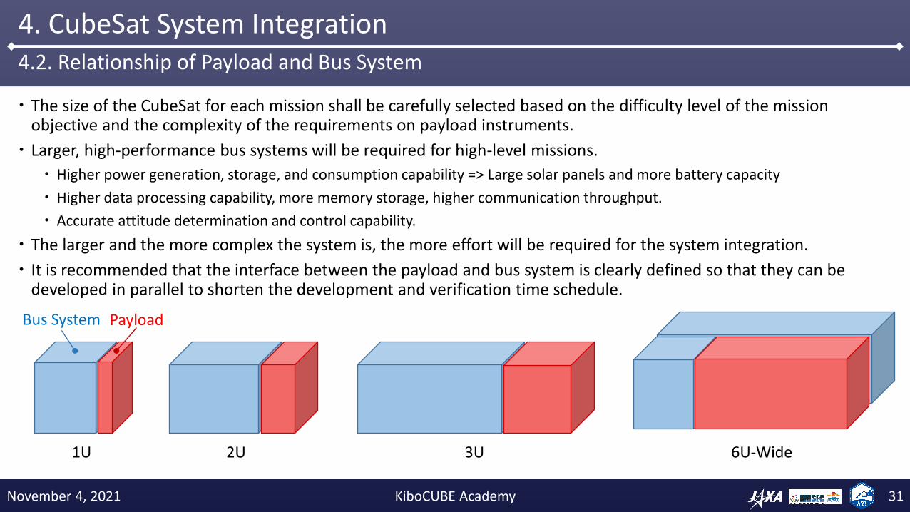
The size of the CubeSat for each mission shall be carefully selected based on the difficulty level of the mission objective and the complexity of the requirements on payload instruments.
Larger, high-performance bus systems will be required for high-level missions.
Higher power generation, storage, and consumption capability => Large solar panels and more battery capacity
Higher data processing capability, more memory storage, higher communication throughput.
Accurate attitude determination and control capability.
The larger and the more complex the system is, the more effort will be required for the system integration.
It is recommended that the interface between the payload and bus system is clearly defined so that they can be developed in parallel to shorten the development and verification time schedule.
4. CubeSat System Integration4.2. Relationship of Payload and Bus System
1U 2U 3U 6U-Wide
PayloadBus System
November 4, 2021 KiboCUBE Academy 31

The requirements of the satellite components shall be defined and driven from the mission objectives and mission requirements. Component requirements include functional requirements, performance requirements, constraints, etc., both for the related hardware and software.
Requirements shall be detailed by a preliminary design review, and component design shall be defined by a critical design review. Components shall be verified in a “bottom-up” manner, followed by a qualification review.
4. CubeSat System Integration4.3. Development and Verification of Satellite Components
Unit Level Verification
V - Model
Performance Requirement Definition
Component Design
Module Level Verification
System Level VerificationFunctional Requirement Definition
Manufacturing
PDR: Preliminary Design Review >
CDR: Critical Design Review >
< QR: Qualification Review
November 4, 2021 KiboCUBE Academy 32

Software functionalities shall be analyzed as the first step and functional requirements shall be identified.
Functions can be classified into some functional groups which are implemented as a software unit for the component.
Development schedules and progress of each hardware and software element shall be managed, and the order of their integration and verification shall be defined in order to control the development schedule.
Unit tests can be at any level and any kind, in order to ensure that the components fulfill the requirements.
Identification of verification items is critically important for the mission success. Need experience!
4. CubeSat System Integration4.4. Hardware and Software Development and Verification Process
Hardware
Software 1Functional Analysis・Function 1 – Command Processing・Function 2 – Housekeeping ・Function 2.1 – Temp. Measurement・Function 2.2 – Heater Control・Function 3 – Image acquisition ・Function 3A – Image processing・etc…
Function Grouping ・Function Group 1
・Function Group 2
・Function Group 3
Software 2
Software 3
Hardware SelectionMake or Buy
Development & Verification ManagementUnit Test
System Integration
Unit Test
ComponentTest
Unit Test
ModuleTest
ModuleTest
November 4, 2021 KiboCUBE Academy 33

Single computer architecture can realize a high degree of system integration with minimum hardware configuration. However, software development of each functional block depends on each other and tends to take more time than the distributed architectures, which enables parallel and independent development of each functional block.
4. CubeSat System Integration4.5. Computer Architecture and Software Configuration
Main Computer
PowerControl
AttitudeControl
PayloadControl
PowerControl
Software
AttitudeControl
Software
PayloadControl
Software
Main Computer
PowerControl
CommandProcessing
PayloadControl
PowerControl
Software
AttitudeControl
Software
PayloadControl
Software
Attitude Control Computer
CommandProcessingSoftware
Payload Control Computer
Power Control Computer
CommandProcessingSoftware
AttitudeControl
CommandProcessing
Centralized Single Computer Distributed Computers
interface
interface interface
interface
November 4, 2021 KiboCUBE Academy 34

Software units to be implemented and executed in a computer shall be integrated into a single piece of on-board software, paying attention to their execution order and logical relationships in between.
The time period required for each of these software tasks shall be controlled so that the on-board computer can execute all the required tasks in the pre-defined required time period, periodically.
4. CubeSat System Integration4.6. Software Integration
Computer
Software 1
Software 2
Software 3
Software 4
Software 5
t
Software Execution
Software 1
Software 2
Software 3Software 4
Software 5
Periodical Execution
November 4, 2021 KiboCUBE Academy 35

Software can be implemented either in a “bare-metal” way or using a Real-Time Operating System (RTOS).
Relatively high-performance computers can utilize RTOS due to its overhead.
Bare-metal implementation requires more precise tuning of the timing by the programmer.
RTOS enables precise timing control of the execution and ease of parallel execution of more than one software units.
4. CubeSat System Integration4.7. Software Operating System
t
Bare-Metal Implementation
Software 1
Software 2
Software 3
Software 4
Software 5
t
Real-Time Operating System Implementation
Software 1
Software 2
Software 3
Software 4
Software 5
Interrupt Interrupt
November 4, 2021 KiboCUBE Academy 36

Attitude determination and control software processes includes software functional groups, such as guidance, navigation, and control, and their careful implementation to achieve high-precision attitude control.
4. CubeSat System Integration4.8. Attitude Determination and Control Software Implementation
Attitude Determination and Control Software Process
© Tohoku University
November 4, 2021 KiboCUBE Academy 37

A computer system can be constructed through a System-on-a-Chip (SoC) design approach. Recent advanced of FPGA (Field-Programmable Gate Array) technology allows you to implement CPU and custom peripheral interface logics inside a single FPGA chip.
Large number of peripheral components can be connected to the computer.
4. CubeSat System Integration4.9. System Integration through System-on-a-Chip Implementation
Attitude Control Computer
FPGA
RTL
SRAMMemories
FlashMemories
FlashMemories
SoftcoreProcessor
IP Core
IP Core
IP CoreIP Core
IP CoreIP Core
IP Core
IP Core
IP Core
Debug
DebugStar Tracker
Fiber Optical GyroscopeSatellite Main
Computer
Reaction WheelReaction WheelReaction Wheel
Reaction Wheel
System-on-a-Chip Design Approach – An example of Micro-satellite (RISESAT) Attitude Control System
© Tohoku University
November 4, 2021 KiboCUBE Academy 38

Standardization of hardware and software can realize satellite system integration through Plug-and-Play (PnP).
There are several PnP standards suggested for several types of interfaces, such as I2C, USB, SpaceWire, etc.
Through PnP technology, one can minimize the system integration effort and maximize reusability.
4. CubeSat System Integration4.10. System Integration through Plug-and-Play
Main Computer
PeripheralComputer
Router
PeripheralComputer
PeripheralComputer
Software
Software Software Software
Plug-and-Play Architecture PnP Computer of Micro-satellite RISESAT
OceanObservation
Camera
Multi-spectralCamera
© Tohoku University / AAC Clyde Space
November 4, 2021 KiboCUBE Academy 39

SystemIntegration
Satellite system integration takes place in a bottom-up manner, starting from the hardware and software integration of each component, integration between components, and integration between the bus system and payload.
Assembly and testing shall be conducted in each integration test. This activity is sometimes referred as Assembly, Integration, and Test (AIT).
The scope of the system level testing shall include testing together with the ground stations and launch vehicles, or its interfaces.
Satellite hardware and software functionalities shall be tested and calibrated even after the launch, in order to ensure that the satellite can fulfil the mission requirements.
4. CubeSat System Integration4.11. Satellite System Integration and Testing
Hardware
Software
ComponentIntegration
Component TestUnit Test
ComponentIntegration
ComponentIntegration
Module Test
Software
Module TestModule Test
Unit Test
Launch
Orbit Verification / Calibration
Mission
System Test
Ground Station Rocket
PayloadBus System
Satellite
November 4, 2021 KiboCUBE Academy 40

5. CubeSat Functional Verification
November 4, 2021 KiboCUBE Academy 41

Verification processes of a satellite can start from the Bread Board Model (BBM) concept verification.
Detailed design solution of the satellite is verified using Engineering Model (EM).
Flight Model (FM) is manufactured based on the verified design through EM, and minimum required tests are applied to obtain qualification for the launch.
Sometimes a mechanical test model is utilized before the manufacturing of the structure of the EM.
5. CubeSat Functional Verification5.1. Verification Process
© Kyutech
PDR
Component Test
Module Test
System Test
Satellite Verification Process
BBM(Bread Board Model)
EM(Engineering Model)
FM(Flight Model)
Component Test
Module Test
System Test
Component Test
Module Test
CDR
QR
LRR
MTM
(Mec
han
ical
Tes
t M
od
el)
November 4, 2021 KiboCUBE Academy 42

Ground testing facilities are required to conduct tests of electrical functionalities of the satellite components and satellite system.
Software-based simulators are utilized for hardware-in-the-loop tests in real-time in order to verify the correct functionalities of on-board software running on the actual flight hardware.
5. CubeSat Functional Verification5.2. Electrical Testing
© Tohoku University
November 4, 2021 KiboCUBE Academy 43

Full software simulators are very useful for the simulation of the satellite’s orbital and attitude behavior.
The simulation process can be accelerated to conduct a large number of simulation trials.
On-board software can be developed using this kind of simulation, software development, and verification environment.
5. CubeSat Functional Verification5.3. Software Simulation
Space Environment
Actuators
On-board ComputerSoftware Model
Actuators
20Hz loop
Satellite Dynamics
Initial Conditions
Simulation Results
Orbit / AttitudeSatellite Form
Earth Gravitational Field,Atmospheric density,Geomagnetic Field, etc.
Orbit / Attitude
SensorDummy Output
Actuator Commands
Torque / Force
Orbit / Attitude
SensorsSensors
SimulatorMonitor Software
Satellite CG-Viewer
Flight Software
Satellite structuralcharacteristics
© Tohoku University
November 4, 2021 KiboCUBE Academy 44

“Fit check” is a one of the most important tests of a CubeSat. A CubeSat’s mechanical and electrical compatibilities are tested using a mechanical Fit Check model of the CubeSat deployment pod.
The manufacturing and integration of the mechanical system shall fulfill the mechanical requirements posed on CubeSats, such as dimension tolerance, surface accuracy, contact of mechanical switches, etc.
Not only the structural design, but also the satellite integration process, shall be planned in the way that the satellite assembly and integration process is reproducible.
It is very important that the assembly, integration and test results are carefully recorded in documents.
5. CubeSat Functional Verification5.4. Fit Check
© JAXA© JAXA
November 4, 2021 KiboCUBE Academy 45

Operational training shall be started at an early stage of the satellite development, so that the verified software and procedure can be reflected to the flight software.
Ground station software and on-board software shall be developed and tested in parallel.
Satellite operation planning skills shall be established within the team using the environment.
Mission lifetime of a satellite is limited, and hence, effective operation of the satellite is indispensable in order to ensure a secure operation of the satellite and to obtain maximum achievements.
5. CubeSat Functional Verification5.5. Operation Training
November 4, 2021 KiboCUBE Academy 46

6. CubeSat Project Management
November 4, 2021 KiboCUBE Academy 47

Space Education through Small Satellite Projects
Project members and students experience:
Mission Analysis
System Design
System Development
Component Procurement
Component Development
System Integration
On-board Software / Algorithm Development
Ground Verification
Ground Environmental Test
Safety Design, Safety Review
Satellite Delivery and Launch
Ground Station Installation
Satellite Operation, Instrument Calibration
Satellite Data Analysis
6. CubeSat Project Management6.1. Hands-on Space Engineering Education
© KIT
© Tohoku University
November 4, 2021 KiboCUBE Academy 48

“Start small, go big!”
Recently, CubeSats have become a major game-changer in the world.
Thanks to the technological advancement of small satellites, CubeSats are no longer for education only, but for actual space development and utilization.
Achievements obtained from smaller CubeSats can be directly applied to larger satellites for even more advanced missions.
1U CubeSats bring everything within your reach!
6. CubeSat Project Management6.2. Stepwise Development of CubeSats and Beyond
CubeSats are Dream Enablers!
© AAC Clyde Space
© Tohoku University
© Tohoku University© Tohoku University
November 4, 2021 KiboCUBE Academy 49

6. CubeSat Project Management6.3. UNISEC Space Engineering Education Activities
University Space Engineering Consortium
No one will be left behind!
November 4, 2021 KiboCUBE Academy 50

KiboCUBE
JAXA/UNOOSA program
Provide opportunities for educational and research institutions from developing economies and economies in transition which are United Nations Member States.
BIRDS Program
Kyushu Institute of Technology (Kyutech)
CubeSat development, hands-on training, education, academic program.
RWASAT-1
University of Tokyo
CubeSat development, hands-on training, education.
Micro-Satellite Program
Tohoku University and Hokkaido University
50-kg-class Earth observation micro-satellite projects
Hands-on activities, education, academic program.
Establishment of Asia Micro-satellite Consortium (AMC).
JAXA and Japanese Universities have strong collaborative relationships.
6. CubeSat Project Management6.4. International Space Engineering Education Opportunities
© JAXA
© University of Tokyo/Arkedge Space/RURA
© JAXA
© Kyutech
November 4, 2021 KiboCUBE Academy 51
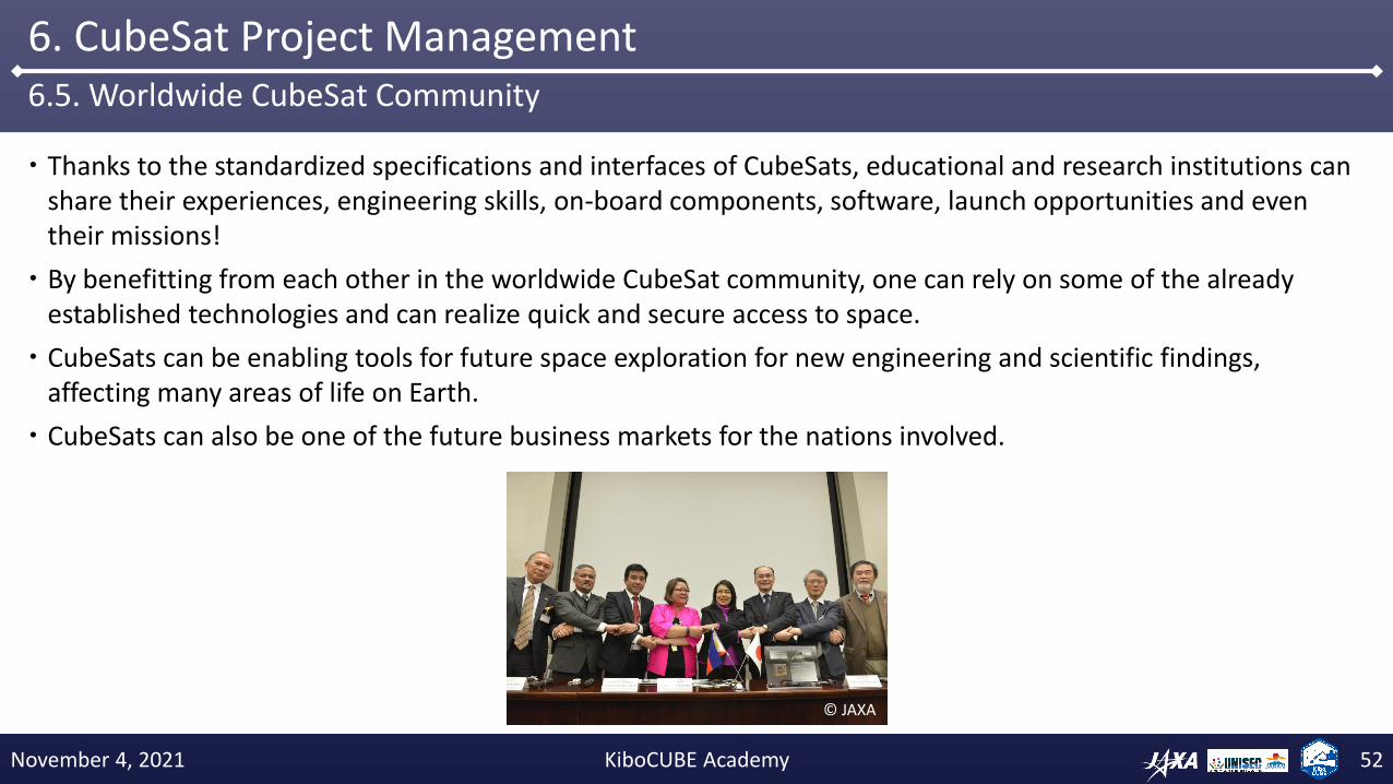
Thanks to the standardized specifications and interfaces of CubeSats, educational and research institutions can share their experiences, engineering skills, on-board components, software, launch opportunities and even their missions!
By benefitting from each other in the worldwide CubeSat community, one can rely on some of the already established technologies and can realize quick and secure access to space.
CubeSats can be enabling tools for future space exploration for new engineering and scientific findings, affecting many areas of life on Earth.
CubeSats can also be one of the future business markets for the nations involved.
6. CubeSat Project Management6.5. Worldwide CubeSat Community
© JAXA
November 4, 2021 KiboCUBE Academy 52

7. Conclusion
November 4, 2021 KiboCUBE Academy 53

System engineering processes of CubeSats are introduced, step-wise development activities and review processes are described. The definition of satellite subsystems, as well as relationships of the payload and bus system is explained.
CubeSat-related standards are introduced, launch opportunities and available mechanical form factors are described.
CubeSat system interface was introduced in terms of electrical interconnections between satellite components, system block diagrams, system configuration design, power distributions, communications, and mechanical interfaces.
System integration and verification processes, as well as their engineering aspects, were described both in hardware and software aspects. Some related advanced topics were introduced, such as System-on-a-chip design method and Plug-and-Play system integration method.
CubeSat functional verification method was introduced. Topics such as environmental testing, electrical functional verification, fit check with the deployment pod, and operation training were discussed.
Important aspects of CubeSat project management in terms of system integration and capacity building were discussed.
CubeSats, are now changing the game of space development and utilization through their low-cost rapid development characteristics, which are based on standardized specifications and interfaces.
CubeSats are the best platform for getting started with space development and utilization, and KiboCUBE Academy facilitates access to space for becoming spacefaring nations.
7. Conclusion
November 4, 2021 KiboCUBE Academy 54

[Disclaimer]The views and opinions expressed in this presentation are those of the authors and do not necessarily reflect those of the United Nations.
Thank you very much.
KiboCUBE Academy 55November 4, 2021