System Design and Control of an Apple Harvesting Robot - arXiv
8
1 System Design and Control of an Apple Harvesting Robot Kaixiang Zhang * , Kyle Lammers * , Pengyu Chu, Zhaojian Li, and Renfu Lu Abstract—There is a growing need for robotic apple harvesting due to decreasing availability and rising cost in labor. Towards the goal of developing a viable robotic system for apple harvesting, this paper presents synergistic mechatronic design and motion control of a robotic apple harvesting prototype, which lays a critical foundation for future advancements. Specifically, we develop a deep learning-based fruit detection and localization system using an RGB-D camera. A three degree-of-freedom manipulator is then designed with a hybrid pneumatic/motor actuation mechanism to achieve fast and dexterous movements. A vacuum-based end-effector is used for apple detaching. These three components are integrated into a robotic apple harvesting prototype with simplicity, compactness, and robustness. More- over, a nonlinear velocity-based control scheme is developed for the manipulator to achieve accurate and agile motion control. Test experiments are conducted to demonstrate the performance of the developed apple harvesting robot. Index Terms—Mechatronic design, motion control, apple har- vesting, agricultural robot. I. I NTRODUCTION A PPLE harvesting is a physically strenuous and labor intensive task. It is estimated that the seasonal agricul- tural workforce required for apple harvesting in the U.S. is more than 10 million worker hours annually, accounting for about 15% of the total production cost [1]. The long-term profitability and sustainability of the apple industry has been eroded due to the decreasing availability and rising cost in the labor market. Moreover, manual picking activities expose the workers to great risks of ergonomic injury and musculoskeletal pain, as manual picking involves extensive repetitive body motions and awkward postures (especially when picking fruits at high locations or deep in the canopy, and repetitively ascending and descending on ladders with heavy loads) [2]. As such, there is an imperative need for automated apple picking to address the aforementioned concerns. Existing automated apple harvesting systems can be gener- ally categorized as shake-and-catch harvesting [3]–[6] or fruit- by-fruit harvesting [7]–[10]. A shake-and-catch harvesting system vibrates the branches or trunk of the tree to detach apples, and a catching device is then employed to catch the falling apples. These systems are efficient in detaching apples. However, they could not avoid bruising caused by apple-to-apple, apple-to-tree, and apple-to-container collisions, Kaixiang Zhang, Kyle Lammers, Pengyu Chu, and Zhaojian Li are with the Department of Mechanical Engineering, Michigan State University, East Lansing, MI 48824, USA (e-mail: [email protected]; [email protected]; [email protected]; [email protected]). Renfu Lu is with the United States Department of Agriculture Agricultural Research Service, East Lansing, MI 48824, USA (e-mail: [email protected]). * Both authors contributed equally to this work. and hence they have not been adopted by the apple industry [5]. On the other hand, fruit-by-fruit selective harvesting systems are developed with the aid of mechatronics and robotic technologies, which generally consist of a vision-based perception component, a manipulator, and an end-effector. The manipulator of such systems picks apples sequentially, and thus the fruit damage can be reduced substantially. However, the fruit-by-fruit harvesting system requires multi-disciplinary advances to enable various synergistic functionalities, includ- ing perception, manipulation, and control. Specifically, the perception module typically exploits sensors like cameras and lidars mounted on the robot to detect and localize the apples [11]–[13]. With the target positions provided by the perception system, the control system directs the manipulator to approach the fruit. A specialized end-effector (e.g., gripper or vacuum tube) then detaches the apple from the tree and drop it to a receiving device or container [14]. As fruit-by-fruit robotic picking is more appealing to the apple industry, it will be the focus of this paper. Over the past two decades, several fruit-by-fruit robotic apple harvesting systems have been developed [7]–[10]. For example, a 7 degree-of-freedom (DOF) industrial manipulator and a silicone funnel shaped gripper with an internal camera are developed in [7]. The system scans the orchard canopy from 40 look-out positions, and for each position the ripe apples are detected and picked one-by-one in a looped task. In [10], an apple harvesting robot is developed with a global camera, a 7 DOF manipulator, and a finger-based end-effector. Instead of attaching the camera to the end-effector as in [7] and [8], the global camera, independent of other parts of the harvesting system, is employed to provide a larger field of view. For both robotic systems reported in [7] and [10], a 7 DOF manipulator is required to approach the fruit. While the 7 DOF manipulator can provide high maneuverability, it is overly complicated and extravagant for practical use. During the apple picking process, the manipulator needs to approach fruits located at various positions within the workspace, and it thus requires a robust and accurate motion control scheme. Several advances have been made in manip- ulator control for robotic harvesting. For example, a two-step control method is developed in [7], where the manipulator is initially adjusted such that the camera’s optical axis points straight to the apple and it is then controlled to reach out to the apple along the optical axis. This two-step method can be used in unstructured orchard environments, but it leads to discontinuous manipulation motion and low harvesting efficiency. Another control scheme is developed in [10], which regulates the end-effector along a horizontal path or 45 ◦ arXiv:2010.11296v1 [cs.RO] 21 Oct 2020
-
Upload
khangminh22 -
Category
Documents
-
view
1 -
download
0
Transcript of System Design and Control of an Apple Harvesting Robot - arXiv
1
System Design and Control of an Apple HarvestingRobot
Kaixiang Zhang∗, Kyle Lammers∗, Pengyu Chu, Zhaojian Li, and Renfu Lu
Abstract—There is a growing need for robotic apple harvestingdue to decreasing availability and rising cost in labor. Towards thegoal of developing a viable robotic system for apple harvesting,this paper presents synergistic mechatronic design and motioncontrol of a robotic apple harvesting prototype, which laysa critical foundation for future advancements. Specifically, wedevelop a deep learning-based fruit detection and localizationsystem using an RGB-D camera. A three degree-of-freedommanipulator is then designed with a hybrid pneumatic/motoractuation mechanism to achieve fast and dexterous movements.A vacuum-based end-effector is used for apple detaching. Thesethree components are integrated into a robotic apple harvestingprototype with simplicity, compactness, and robustness. More-over, a nonlinear velocity-based control scheme is developed forthe manipulator to achieve accurate and agile motion control.Test experiments are conducted to demonstrate the performanceof the developed apple harvesting robot.
Index Terms—Mechatronic design, motion control, apple har-vesting, agricultural robot.
I. INTRODUCTION
APPLE harvesting is a physically strenuous and laborintensive task. It is estimated that the seasonal agricul-
tural workforce required for apple harvesting in the U.S. ismore than 10 million worker hours annually, accounting forabout 15% of the total production cost [1]. The long-termprofitability and sustainability of the apple industry has beeneroded due to the decreasing availability and rising cost in thelabor market. Moreover, manual picking activities expose theworkers to great risks of ergonomic injury and musculoskeletalpain, as manual picking involves extensive repetitive bodymotions and awkward postures (especially when picking fruitsat high locations or deep in the canopy, and repetitivelyascending and descending on ladders with heavy loads) [2]. Assuch, there is an imperative need for automated apple pickingto address the aforementioned concerns.
Existing automated apple harvesting systems can be gener-ally categorized as shake-and-catch harvesting [3]–[6] or fruit-by-fruit harvesting [7]–[10]. A shake-and-catch harvestingsystem vibrates the branches or trunk of the tree to detachapples, and a catching device is then employed to catchthe falling apples. These systems are efficient in detachingapples. However, they could not avoid bruising caused byapple-to-apple, apple-to-tree, and apple-to-container collisions,
Kaixiang Zhang, Kyle Lammers, Pengyu Chu, and Zhaojian Li are withthe Department of Mechanical Engineering, Michigan State University, EastLansing, MI 48824, USA (e-mail: [email protected]; [email protected];[email protected]; [email protected]).
Renfu Lu is with the United States Department of Agriculture AgriculturalResearch Service, East Lansing, MI 48824, USA (e-mail: [email protected]).
* Both authors contributed equally to this work.
and hence they have not been adopted by the apple industry[5]. On the other hand, fruit-by-fruit selective harvestingsystems are developed with the aid of mechatronics androbotic technologies, which generally consist of a vision-basedperception component, a manipulator, and an end-effector. Themanipulator of such systems picks apples sequentially, andthus the fruit damage can be reduced substantially. However,the fruit-by-fruit harvesting system requires multi-disciplinaryadvances to enable various synergistic functionalities, includ-ing perception, manipulation, and control. Specifically, theperception module typically exploits sensors like cameras andlidars mounted on the robot to detect and localize the apples[11]–[13]. With the target positions provided by the perceptionsystem, the control system directs the manipulator to approachthe fruit. A specialized end-effector (e.g., gripper or vacuumtube) then detaches the apple from the tree and drop it toa receiving device or container [14]. As fruit-by-fruit roboticpicking is more appealing to the apple industry, it will be thefocus of this paper.
Over the past two decades, several fruit-by-fruit roboticapple harvesting systems have been developed [7]–[10]. Forexample, a 7 degree-of-freedom (DOF) industrial manipulatorand a silicone funnel shaped gripper with an internal cameraare developed in [7]. The system scans the orchard canopyfrom 40 look-out positions, and for each position the ripeapples are detected and picked one-by-one in a looped task.In [10], an apple harvesting robot is developed with a globalcamera, a 7 DOF manipulator, and a finger-based end-effector.Instead of attaching the camera to the end-effector as in [7]and [8], the global camera, independent of other parts of theharvesting system, is employed to provide a larger field ofview. For both robotic systems reported in [7] and [10], a 7DOF manipulator is required to approach the fruit. While the7 DOF manipulator can provide high maneuverability, it isoverly complicated and extravagant for practical use.
During the apple picking process, the manipulator needsto approach fruits located at various positions within theworkspace, and it thus requires a robust and accurate motioncontrol scheme. Several advances have been made in manip-ulator control for robotic harvesting. For example, a two-stepcontrol method is developed in [7], where the manipulator isinitially adjusted such that the camera’s optical axis pointsstraight to the apple and it is then controlled to reach outto the apple along the optical axis. This two-step methodcan be used in unstructured orchard environments, but itleads to discontinuous manipulation motion and low harvestingefficiency. Another control scheme is developed in [10], whichregulates the end-effector along a horizontal path or 45
arX
iv:2
010.
1129
6v1
[cs
.RO
] 2
1 O
ct 2
020
2
inclined path to reach the fruits. This scheme is only effectivefor V-trellis orchard architectures and would not be suitablefor other modern structured orchards.
Despite the aforementioned efforts, there are still no com-mercially available robotic harvesting systems for tree fruitsbecause the developed systems are still unsatisfactory inperformance, too complicated or expensive to be economicallyviable, and unreliable or inefficient for working in the realorchard environment [11], [15]. To lay a foundation for auto-mated apple harvesting, this paper presents the developmentof a new robotic apple harvesting prototype. Specifically, anRGB-D camera is exploited as the primary sensor, and a deeplearning-based perception module is developed for apple de-tection and localization. A 3 DOF manipulator and a vacuum-based end-effector are designed to approach and detach theapple, respectively. Different from previous studies that relyon high DOF industrial manipulators, the developed 3 DOFmanipulator has simple and compact structure while providinghigh picking efficiency. Furthermore, a motion control schemeis designed to ensure the manipulator can approach apples withsatisfactory accuracy. Experiments are conducted to illustratethe performance of the integrated system.
The main contributions of this paper include the following.Firstly, we present the synergistic development of a roboticapple harvesting prototype that is simple in design, fast inactuation, and efficient in fruit picking. Secondly, the nonlinearcontrol strategy is designed by fully exploiting the mechanicalstructure of the manipulator, which can avoid discontinu-ous manipulation motion and accomplish more agile appleapproaching compared to [7], [10]. Last but not least, theexperimental studies validate the design concept and underpinfuture research.
The remainder of this paper is organized as follows. SectionII presents the system design of the apple harvesting robotwhereas Section III details the motion control scheme. Exper-iment results are provided in Section IV. Finally, conclusionsare drawn in Section V.
II. SYSTEM DESIGN
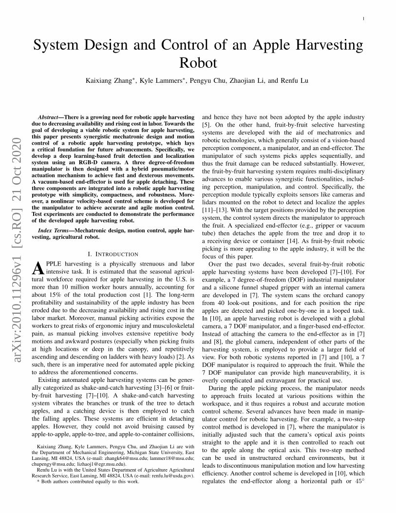
Our developed harvesting robot prototype is illustrated inFig. 1. The hardware consists primarily of three modules:an Intel RealSense RGB-D camera, a 3 DOF manipulator,and a vacuum-based end-effector. Auxiliary units (e.g., powersupply, vacuum pump) are placed on the rear side of thesystem (near the left lower corner in the image). Those unitsare connected to a laptop (Intel i5-6700 CPU and 16 GBRAM). The robot operating system (ROS) is utilized to fullyintegrate the entire system and facilitate the communicationand control of the modules. Below is a detailed description ofeach module.
A. Visual Perception
The first and foremost task of automated apple harvestingis the detection and localization of fruits on the tree. Appledetection is to segment apples from the background (i.e.,foliage, branches and trunks), while fruit localization refersto calculating the three-dimensional spatial position of the
Fig. 1. The developed robotic apple harvesting prototype.
detected apples relative to the camera frame. In our system, anIntel RealSense D435i RGB-D camera is used to capture theenvironmental information, because of its compactness, lowcost, and accuracy (1280× 720 active stereo depth resolution[16]).
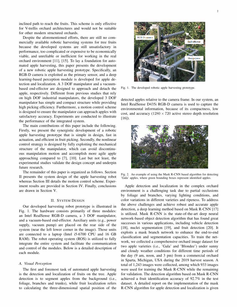
Fig. 2. An example of using the Mask R-CNN based algorithm for detecting’Gala’ apples, where green bounding boxes represent identified apples.
Apple detection and localization in the complex orchardenvironment is a challenging task due to partial occlusionsby foliage and branches, varying lighting conditions, andcolor variations in different varieties and ripeness. To addressthe above challenges and achieve robust and accurate appledetection, a deep learning method based on Mask R-CNN [17]is utilized. Mask R-CNN is the state-of-the-art deep neuralnetwork-based object detection algorithm that has found greatsuccesses in various applications, including vehicle detection[18], nuclei segmentation [19], and fruit detection [20]. Itexploits a mask branch network to enhance the end-to-endclassification and segmentation capacities. To train the net-work, we collected a comprehensive orchard image dataset fortwo apple varieties (i.e., ’Gala’ and ’Blondee’) under sunnyand cloudy weather conditions for different time periods ofthe day (9 am, noon, and 3 pm) from a commercial orchardin Sparta, Michigan, USA during the 2019 harvest season. Atotal of 1,243 images were collected, among which 933 imageswere used for training the Mask R-CNN while the remainingfor validation. The detection algorithm based on Mask R-CNNachieved a fruit identification accuracy of 92.7% in the testdataset. A detailed report on the implementation of the maskR-CNN algorithm for apple detection and localization is given
3
in [21]. Fig. 2 shows an example of the detection results wheregreen boxes show the identified apples.
With the detected apples in bounding boxes, apple locationsare computed by incorporating the depth information in theIntel RealSense RGB-D camera. Specifically, for each detectedapple, the disparity map is leveraged to generate a rangematrix in the corresponding bounding box. The mean valueof the range matrix is then calculated as the apple’s depthrange. Combining the depth range with the center of thebounding box pixels, the Cartesian position of the apple canbe determined via back-projection [22]. This iterative processis run for each apple area to obtain positions for all detectedapples in the image.
B. Manipulator Design
With the target apple locations provided by the perceptionsystem discussed above, a 3 DOF manipulator is then designedand assembled to efficiently reach the target locations. Aspresented in Fig. 3, the manipulator consists of two revolutejoints and one prismatic joint. The two revolute joints createa pan-and-tilt mechanism and are affixed to the prismaticbase. This design provides a simple and compact mechanicalstructure, which not only offers sufficient DOF for primarypick and place tasks but also facilitates highly efficient motioncontrol.
Fig. 3. Proposed 3 DOF manipulator with two revolute joints and oneprismatic joint.
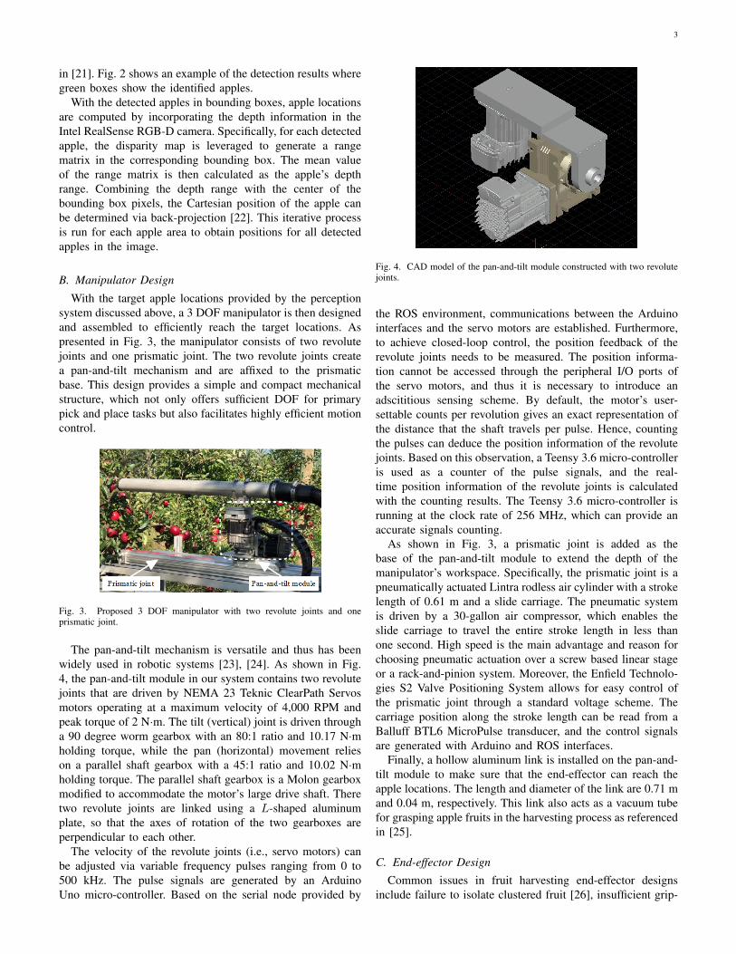
The pan-and-tilt mechanism is versatile and thus has beenwidely used in robotic systems [23], [24]. As shown in Fig.4, the pan-and-tilt module in our system contains two revolutejoints that are driven by NEMA 23 Teknic ClearPath Servosmotors operating at a maximum velocity of 4,000 RPM andpeak torque of 2 N·m. The tilt (vertical) joint is driven througha 90 degree worm gearbox with an 80:1 ratio and 10.17 N·mholding torque, while the pan (horizontal) movement relieson a parallel shaft gearbox with a 45:1 ratio and 10.02 N·mholding torque. The parallel shaft gearbox is a Molon gearboxmodified to accommodate the motor’s large drive shaft. Theretwo revolute joints are linked using a L-shaped aluminumplate, so that the axes of rotation of the two gearboxes areperpendicular to each other.
The velocity of the revolute joints (i.e., servo motors) canbe adjusted via variable frequency pulses ranging from 0 to500 kHz. The pulse signals are generated by an ArduinoUno micro-controller. Based on the serial node provided by
Fig. 4. CAD model of the pan-and-tilt module constructed with two revolutejoints.
the ROS environment, communications between the Arduinointerfaces and the servo motors are established. Furthermore,to achieve closed-loop control, the position feedback of therevolute joints needs to be measured. The position informa-tion cannot be accessed through the peripheral I/O ports ofthe servo motors, and thus it is necessary to introduce anadscititious sensing scheme. By default, the motor’s user-settable counts per revolution gives an exact representation ofthe distance that the shaft travels per pulse. Hence, countingthe pulses can deduce the position information of the revolutejoints. Based on this observation, a Teensy 3.6 micro-controlleris used as a counter of the pulse signals, and the real-time position information of the revolute joints is calculatedwith the counting results. The Teensy 3.6 micro-controller isrunning at the clock rate of 256 MHz, which can provide anaccurate signals counting.
As shown in Fig. 3, a prismatic joint is added as thebase of the pan-and-tilt module to extend the depth of themanipulator’s workspace. Specifically, the prismatic joint is apneumatically actuated Lintra rodless air cylinder with a strokelength of 0.61 m and a slide carriage. The pneumatic systemis driven by a 30-gallon air compressor, which enables theslide carriage to travel the entire stroke length in less thanone second. High speed is the main advantage and reason forchoosing pneumatic actuation over a screw based linear stageor a rack-and-pinion system. Moreover, the Enfield Technolo-gies S2 Valve Positioning System allows for easy control ofthe prismatic joint through a standard voltage scheme. Thecarriage position along the stroke length can be read from aBalluff BTL6 MicroPulse transducer, and the control signalsare generated with Arduino and ROS interfaces.
Finally, a hollow aluminum link is installed on the pan-and-tilt module to make sure that the end-effector can reach theapple locations. The length and diameter of the link are 0.71 mand 0.04 m, respectively. This link also acts as a vacuum tubefor grasping apple fruits in the harvesting process as referencedin [25].
C. End-effector Design
Common issues in fruit harvesting end-effector designsinclude failure to isolate clustered fruit [26], insufficient grip-

4
ping strength [27], low harvesting efficiency from high cycletimes [28], and damage to the fruit, canopy structures, or theend-effector itself due to bulky mechanical components [29].Thus, end-effector design is a significant challenging task forresearchers, and a wide range of design concepts have beenstudied with varying degrees of effectiveness and efficiency.In our system, a vacuum-based end-effector is utilized. It hasbeen shown that the vacuum-based end-effector is effective ingrasping and detaching tree fruits while minimizing bruising[30]. Additionally, when the manipulator does not approachthe apple accurately, the vacuum-based end-effector can toler-ate the approaching error since it can attract the fruit withina certain distance when sufficient vacuum flow is provided.This is important for in-field applications where unpredictableenvironmental factors (e.g., instantaneous movement of fruitsdue to disturbances from winds and the traveling robot plat-form, uneven orchard terrain, etc.) may adversely affect thesystem performance (i.e., accuracy in fruit localization androbot control and movement). Selection of an appropriatediameter of the end-effector is critical, so that it can achieve aproper flow rate and vacuum pressure that is needed to grip anddetach fruits of different size, while maintaining the agility ofnavigating in and out of the tree canopies. Through preliminarystudies, the end-effector diameter of 0.04 m is determined tobe adequate for the current robotic system.
The rear end of the end-effector tube of the robot isconnected to a Craftsman electric powered wet/dry vacuumvia a flexible and expandable tube. During fruit picking, thevacuum machine operates in continuous mode, which cangenerate a peak horsepower of 5.5 HP.
III. MOTION CONTROL
For an apple harvesting system, the manipulator needs toapproach the apples located at different positions with highaccuracy and flexibility. To achieve this goal, a motion controlstrategy is presented in this section by fully exploiting themechanical structure of the developed 3 DOF manipulator.
A. Kinematic Model
Fig. 5. Kinematical description of the 3 DOF manipulator.
The kinematical description of the 3 DOF manipulator isshown in Fig. 5. Let
[x, y, z
]T ∈ R3 be the position ofthe end-effector expressed in terms of the base frame Fb of
the manipulator. According to the kinematical diagram shownin Fig. 5 and the Denavit–Hartenberg convention [31], thefollowing forward kinematics function can be obtained:
x = d3 cos(θ) cos(ϕ) +D,
y = d3 sin(ϕ) + d2,
z = −d3 sin(θ) cos(ϕ) + d1,
(1)
where d1, d2, d3 ∈ R are the link length, and[ϕ, θ,D
]T ∈ R3
are the joint variables. The values of link length and jointvariables are listed in Table I. It is clear that (1) charac-terizes the position of the end-effector as a function of thejoint parameters
[ϕ, θ,D
]T. From (1) and the facts that ϕ,
θ ∈ (−25, 25), it turns out that
ϕ = arcsin(y − d2d3
),
θ = arcsin(d1 − zd3 cos(ϕ)
),
D = x− d3 cos(θ) cos(ϕ),
(2)
which characterizes the inverse kinematics to calculate thejoint parameters
[ϕ, θ,D
]Tfrom the position of the end-
effector[x, y, z
]T. Generally, gradient-based optimization
solvers [32], [33] can be used to compute the inverse kine-matics of a manipulator. However, since the developed 3 DOFmanipulator has a simple and exploitable structure, its inversekinematics can be determined by the analytical expression in(2), which can avoid iterative and complex optimization pro-cedure that is more time consuming and can induce numericalerrors.
TABLE IMODEL PARAMETERS OF THE 3 DOF MANIPULATOR
Parameter ValueLink d1 0.0635 mLink d2 0.0889 mLink d3 0.6985 m
Revolute joint ϕ (−25, 25)Revolute joint θ (−25, 25)
Prismatic joint D (0m, 0.61m)
B. Controller Development
As described in Section II-A, the proposed perception algo-rithm can provide the apple locations expressed in the cameraframe. By using conventional calibration techniques [34], thetransformation matrix between the camera frame and the baseframe of the manipulator can be determined. Then, the applelocation under the manipulator coordinate frame can be calcu-lated via the transformation matrix. Let
[xd, yd, zd
]T ∈ R3 bethe detected apple position. The control objective is to regulatethe end-effector to approach the apple position
[xd, yd, zd
]Tfrom the home position
[x0, y0, z0
]T ∈ R3. Note that therevolute joint parameters ϕ, θ and prismatic joint parameter Dare driven by distinct dynamic mechanisms (motor-based andpneumatic), and hence different control schemes are designedfor these two types of joints. Specifically, the revolute joints ϕ,

5
θ are regulated with the velocity-based control method, whilethe position-based controller is used to adjust the prismaticjoint D. The velocity-based control method can generateexplicit speed command to smoothly adjust the revolute jointsbased on real-time position feedback, which is more accurateand robust than the position-based controller. However, theposition feedback of the current pneumatic prismatic joint isnot available, therefore, position-based control method is usedfor the prismatic joint.
The velocity-based control scheme for the revolute joints ispresented next. Based on (1), it can be found that the end-effector position along the yb-axis and zb-axis is determinedby ϕ and θ. Therefore, the revolute joints are driven to ensurethat
[y, z
]Tconverges to
[yd, zd
]T. To achieve this task, the
quintic function [31] is exploited to generate a reference tra-jectory
[yr, zr
]T ∈ R2 and then the aforementioned regulationproblem will be transformed into a trajectory tracking problem.More precisely, the quintic function-based reference trajectory[yr, zr
]Thas the following form:
yr(t) = ay0 + ay1t+ ay2t2 + ay3t
3 + ay4t4 + ay5t
5,
zr(t) = az0 + az1t+ az2t2 + az3t
3 + az4t4 + az5t
5,(3)
where ayi, azi ∈ R (i = 0, 1, · · · , 5) are coefficients ofthe quintic function and t denotes time. Given
[y0, z0
]T,[
yd, zd]T
, and a time domain [0, tf ], the reference trajectorysatisfies
yr(0) = y0, yr(tf ) = yd,
yr(0) = yr(0) = yr(tf ) = yr(tf ) = 0,
zr(0) = z0, zr(tf ) = zd,
zr(0) = zr(0) = zr(tf ) = zr(tf ) = 0.
(4)
Based on (3) and (4), the coefficients ayi, azi(i = 0, 1, · · · , 5)can be calculated. Note that the constraints presented in (4)ensure that the initial and final positions of the referencetrajectory will be
[y0, z0
]Tand
[yd, zd
]T, respectively. There-
fore, actuating the revolute joints to make[y, z
]Tfollow the
reference trajectory[yr, zr
]Twill lead to the convergence of[
y, z]T
to[yd, zd
]T. The introduction of the reference trajec-
tory[yr, zr
]Talso brings several additional advantages. First,
the reference trajectory is continuously differentiable, whichis conducive to ensuring that the end-effector approaches thedesired position along a smooth path. Second, by adjusting theparameter tf , the velocity profile of the reference trajectorycan be modified, and thus the end-effector can reach thedesired position within a specific time interval. Based on (1),the time derivative of
[y, z
]Tcan be calculated as:
y = d3 cos(ϕ)ωϕ,
z = −d3 cos(θ) cos(ϕ)ωθ + d3 sin(θ) sin(ϕ)ωϕ,(5)
where ωϕ, ωθ ∈ R are the angular velocity inputs of therevolute joints ϕ and θ, respectively. Furthermore, the errorsignals
[ey, ez
]T ∈ R2 are constructed as
ey = y − yr,ez = z − zr.
(6)
Based on (5), (6), and by virtue of Lyapunov-based controltechniques [35], the velocity controller is designed as
ωϕ =1
d3 cos(ϕ)(−k1ey + yr) ,
ωθ =1
d3 cos(θ) cos(ϕ)(k2ez + d3 sin(θ) sin(ϕ)ωϕ − zr) ,
(7)where k1, k2 ∈ R+ are positive constant gains. The velocitycontroller (7) can ensure that the end-effector position alongthe yb-axis and zb-axis tracks the reference trajectory
[yr, zr
]Tasymptotically, and the detailed stability analysis is given inAppendix A.
We next present the position-based scheme for the prismaticjoint control. As mentioned in Section II-B, the prismatic jointis driven by a pneumatic system. A voltage-based proportional-integral (PI) controller is utilized to regulate the prismaticjoint parameter D. Specifically, given the desired position[xd, yd, zd
]T, the inverse kinematics (2) is used to calculate
the corresponding desired joint parameters[ϕd, θd, Dd
]T.
Then, based on the desired value Dd, the embedded PIcontroller can adjust the prismatic joint to ensure D convergesto Dd.
IV. PERFORMANCE EVALUATION
In this section, comprehensive experiments are reported todemonstrate the performance of the developed robotic appleharvesting system. We first validate the motion control schemedeveloped in Section III and then evaluate the integratedsystem in apple picking scenarios.
A. Motion Control Validation
Since different control schemes are employed for the rev-olute and prismatic joints, their performance is evaluatedseparately in the following.
The velocity controller (7) designed for the revolute jointsϕ and θ is tested firstly. We use open-loop velocity control andposition control approaches as the benchmark to facilitate theperformance evaluation. In particular, the open-loop velocitycontroller is given by
ωϕ =yr
d3 cos(ϕ),
ωθ =1
d3 cos(θ) cos(ϕ)(d3 sin(θ) sin(ϕ)ωϕ − zr) .
(8)
Comparing (7) with (8), it can be found that the developedcontroller exploits the feedback errors
[ey, ez
]Tto achieve
closed-loop control, while the open-loop velocity controllerdoes not include the feedback error terms. The position controlmethod utilizes the positioning mode provided by the NEMA23 Teknic ClearPath Servos to rotate the revolute joints. Morespecifically, given the desired position of the end-effector, thecorresponding desired joint values ϕd and θd can be calculatedvia the inverse kinematics (2), and then the algorithm embed-ded in the positioning mode is called to regulate the servomotor towards the desired joint values. To conduct a thoroughcomparison, three cases are selected. Under each case, the
6
manipulator is controlled by the aforementioned three methodsfrom the same home position to a target position. The desiredpositions for these three cases are chosen as:
Case 1:[xd, yd, zd
]T=
[0.6876m,−0.0505m, 0.011m
]T,
Case 2:[xd, yd, zd
]T=
[0.5874m,−0.1483m, 0.3695m
]T,
Case 3:[xd, yd, zd
]T=
[0.6936m, 0.1938m, 0.01m
]T.
According to (2), the corresponding desired joint values canbe calculated as follows:
Case 1:[ϕd, θd, Dd
]T=
[−11.5, 8.6, 0m
]T,
Case 2:[ϕd, θd, Dd
]T=
[−19.8,−23.1, 0m
]T,
Case 3:[ϕd, θd, Dd
]T=
[8.6, 8.6, 0m
]T.
Note that the prismatic joint parameter Dd is set as zeroin these three cases, aimed at solely validating the controlperformance of the revolute joints. Moreover, to measure thecontrol accuracy, as shown in Fig. 6, a QR code is attached tothe end-effector. The QR code can be detected and localizedby the RGB-D camera stably and precisely, and thus the finalposition of the end-effector can be determined via the QRcode identification. Each control method is tested by running 5times in each case, and the average distance errors between thefinal position of the end-effector and the given desired positionare calculated to facilitate the evaluation. The correspondingresults are shown in Table II. It can be seen that the proposedvelocity control scheme actuates the revolute joints ϕ and θwith higher accuracy for all three cases compared to the othertwo methods.
Fig. 6. Experimental setup for control validation.
TABLE IICOMPARISON OF THE DISTANCE ERRORS (mm) BETWEEN THE FINAL
POSITION AND DESIRED POSITION OF THE MANIPULATOR FOR DIFFERENTREVOLUTE JOINT CONTROL APPROACHES
Case 1 Case 2 Case 3Open-loop velocity control 7.1 14.7 10.8
Position control 6.2 8.6 2.9Proposed velocity control 4.8 8.0 1.9
The evaluation of the position control scheme for theprismatic joint D is presented next. To separately test the
prismatic joint, the revolute joints ϕ and θ are set as zerowhile the prismatic joint D is actuated to achieve the followingdesired values:
Dd = 0.1m, 0.2m, 0.3m.
The movement of the prismatic joint D is measured with theaid of QR code, and the measurement results correspondingto the desired values above are 0.111m, 0.208m, and 0.311m.Moreover, the position control scheme can regulate the pris-matic joint D to approach the given desired values within onesecond in different tests, which satisfies the speed requirementfor practical applications.
B. Apple Harvesting Validation
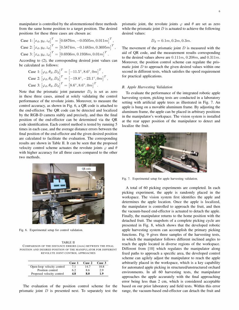
To evaluate the performance of the integrated robotic appleharvesting system, picking tests are conducted in a laboratorysetting with artificial apple trees as illustrated in Fig. 7. Anapple is hung on a movable aluminum frame. By adjusting thealuminum frame, the apple can be placed in arbitrary positionsin the manipulator’s workspace. The vision system is installedat the rear upper position of the manipulator to detect andlocalize the fruit.
Fig. 7. Experimental setup for apple harvesting validation.
A total of 60 picking experiments are completed. In eachpicking experiment, the apple is randomly placed in theworkspace. The vision system first identifies the apple anddetermines the apple location. Once the apple is localized,the manipulator is controlled to approach the fruit, and thenthe vacuum-based end-effector is actuated to detach the apple.Finally, the manipulator returns to the home position with thedetached fruit. The snapshots of a complete picking cycle arepresented in Fig. 8, which shows that the developed roboticapple harvesting system can accomplish the primary pickingfunctions. Fig. 9 gives three samples of the harvesting tests,in which the manipulator follows different inclined angles toreach the apple located in diverse regions of the workspace.Different from [10] which regulates the manipulator alongfixed paths to approach a specific area, the developed controlscheme can agilely adjust the manipulator to reach the applearbitrarily placed in the workspace, which is a key capabilityfor automated apple picking in structured/unstructured orchardenvironments. In all 60 harvesting tests, the manipulatorapproaches the apple accurately with the final approachingerror being less than 2 cm, which is considered acceptablebased on our prior laboratory and field tests. Within this errorrange, the vacuum-based end-effector can detach the fruit and

7
(a) 0s (b) 0.4s (c) 0.8s (d) 1.2s (e) 1.6s
(f) 2.4s (g) 2.8s (h) 3.2s (i) 3.6s (j) 4s
Fig. 8. Snapshots of a harvesting cycle at different time instants.
(a) (b) (c)
Fig. 9. Approaching performance of the manipulator with the apple locatedin different regions of the workspace.
firmly hold the fruit, as the manipulator is returning to thehome position in all tests. Moreover, on average, 0.3 secondis required to detect and localize all fruits in one image. Thetime for the manipulator to approach an individual apple isapproximately 2.0 second, and fruit detaching using an open-loop command is set at 1.0 second.
C. Discussion on Future Work
While the developed prototype demonstrated promisingperformance, further work is needed to improve the system.
It is necessary to introduce additional sensing to improvethe picking efficiency and system robustness. The currentcommand of fruit detaching operates in an open-loop scheme,which is unable to determine if or when the target fruit isdetached from the tree. Installing a pressure sensor on the end-effector can provide feedback information about whether thefruit is held by the end-effector and has been separated fromthe tree after the predetermined movement, which is conduciveto accomplishing closed-loop fruit detaching. Besides, theperception system should be further extended to detect otherobjects, such as branches, to provide a more comprehensiveenvironment perception.
Since many fruits are located deep in the canopy, a pathplanning algorithm needs to be developed and integratedwith the motion controller to ensure that the manipulator
approaches target apples without colliding or damage treebranches or other objects in its path to the target fruit.
The current vacuum-based end-effector is made of alu-minum tube covered with a thin layer of soft foam at itsentrance. While this simple end-effector design is capableto generate sufficient vacuum pressure to detach about 80%of apples from trees in our field tests in 2018 and 2019.Improvements to the end-effector design are needed, so as toachieve at least 95% detaching rate. Different vacuum cupdesigns with different soft materials should be considered,so that the end effector can easily conform to the variablecontours/sizes of apples to allow fast build-up of sufficientvacuum pressure to effectively detach fruits from trees.
V. CONCLUSION
The mechatronic design and motion control of a roboticapple harvesting prototype was presented in this paper. Thisprototype integrated a vision-based perception system, 3 DOFmanipulator, and vacuum-based end-effector to execute applepicking. A control scheme was designed to achieve accu-rate and agile manipulation motion. Laboratory studies for60 picking tests demonstrated that the manipulator reachedthe desired apple positions with the overall error being lessthan 2 cm, which is considered acceptable for the vacuum-based end-effector to detach fruits from trees. The developedprototype met the primary harvesting functionalities, thuslaying a solid foundation for future advancements. Future workwill be focused on automated sensing of fruit holding anddetaching process, optimal path planning for efficient pickingof apples and minimizing potential damage to tree canopies bythe manipulator, and better end-effector design for fast, firmholding and detaching of apples from trees.
APPENDIX ASTABILITY ANALYSIS OF THE VELOCITY CONTROLLER
Theorem 1: The velocity controller developed in (7) ensuresthat the end-effector position along the yb-axis and zb-axis,

8
i.e.,[y, z
]T, converges to the reference trajectory
[yd, zd
]Tasymptotically.
Proof: To prove Theorem 1, a Lyapunov function V ∈ Ris defined as
V ,1
2e2y +
1
2e2z, (9)
where ey and ez are the error signals given in (6). Based on(5) and (6), it can be obtained that
ey = d3 cos(ϕ)ωϕ − yr,ez = −d3 cos(θ) cos(ϕ)ωθ + d3 sin(θ) sin(ϕ)ωϕ − zr.
(10)
Taking the time derivative of (9) and utilizing (7) and (10), itcan be further derived that
V = ey ey + ez ez
= ey (d3 cos(ϕ)ωϕ − yr) + ez (−d3 cos(θ) cos(ϕ)ωθ+d3 sin(θ) sin(ϕ)ωϕ − zr)
= −k1e2y − k2e2z ≤ 0.(11)
According to (9) and (11), the Lyapunov’s stability theorem[35] can be invoked to conclude that ey = 0 and ez = 0 areasymptotically stable, which indicates that
[y, z
]Tconverges
to[yr, zr
]Tasymptotically.
REFERENCES
[1] R. K. Gallardo and S. P. Galinato, 2012 Cost Estimates of Establishing,Producing, and Packing Red Delicious Apples in Washington. Wash-ington State University Extension, 2012.
[2] F. A. Fathallah, “Musculoskeletal disorders in labor-intensive agricul-ture,” Appl. Ergon., vol. 41, no. 6, pp. 738–743, Oct. 2010.
[3] D. L. Peterson, B. S. Bennedsen, W. C. Anger, and S. D. Wolford, “Asystems approach to robotic bulk harvesting of apples,” Trans. ASAE,vol. 42, no. 4, pp. 871–876, 1999.
[4] M. E. De Kleine and M. Karkee, “A semi-automated harvesting pro-totype for shaking fruit tree limbs,” Trans. ASABE, vol. 58, no. 6, pp.1461–1470, 2015.
[5] L. He, H. Fu, D. Sun, M. Karkee, and Q. Zhang, “Shake-and-catchharvesting for fresh market apples in trellis-trained trees,” Trans. ASABE,vol. 60, no. 2, pp. 353–360, 2017.
[6] L. He, X. Zhang, Y. Ye, M. Karkee, and Q. Zhang, “Effect of shakinglocation and duration on mechanical harvesting of fresh market apples,”Appl. Eng. Agric., vol. 35, no. 2, pp. 175–183, 2019.
[7] J. Baeten, K. Donne, S. Boedrij, W. Beckers, and E. Claesen, “Au-tonomous fruit picking machine: A robotic apple harvester,” in Fieldand service robotics. Springer, 2008, pp. 531–539.
[8] Z. De-An, L. Jidong, J. Wei, Z. Ying, and C. Yu, “Design and control ofan apple harvesting robot,” Biosyst. Eng., vol. 110, no. 2, pp. 112–122,2011.
[9] J. R. Davidson, A. Silwal, C. J. Hohimer, M. Karkee, C. Mo, andQ. Zhang, “Proof-of-concept of a robotic apple harvester,” in Proc.IEEE/RSJ Int. Conf. Intell. Robots Syst., Daejeon, Korea, 2016, pp. 634–639.
[10] A. Silwal, J. R. Davidson, M. Karkee, C. Mo, Q. Zhang, and K. Lewis,“Design, integration, and field evaluation of a robotic apple harvester,”J. Field Robot., vol. 34, no. 6, pp. 1140–1159, 2017.
[11] A. Gongal, S. Amatya, M. Karkee, Q. Zhang, and K. Lewis, “Sensorsand systems for fruit detection and localization: A review,” Comput.Electron. Agric., vol. 116, pp. 8–19, Aug. 2015.
[12] A. Plebe and G. Grasso, “Localization of spherical fruits for roboticharvesting,” Mach. Vision Appl., vol. 13, no. 2, pp. 70–79, Nov. 2001.
[13] I. Sa, Z. Ge, F. Dayoub, B. Upcroft, T. Perez, and C. McCool,“Deepfruits: A fruit detection system using deep neural networks,”Sensors, vol. 16, no. 8, pp. 12–22, Aug. 2016.
[14] R. Lu, A. K. Pothula, A. Mizushima, M. VanDyke, and Z. Zhang,“System for sorting fruit,” U.S. Patent 9 919 345, Mar. 20, 2018.
[15] R. Lu, Z. Zhang, and A. K. Pothula, “Innovative technology for appleharvest and in-field sorting,” Fruit Qtly., vol. 25, no. 2, pp. 11–14, 2017.
[16] “Intel®RealSense™camera D400 series product family datasheet,”2020. [Online]. Available: https://www.intelrealsense.com/wp-content/uploads/2020/06/Intel-RealSense-D400-Series-Datasheet-June-2020.pdf
[17] K. He, G. Gkioxari, P. Dollar, and R. Girshick, “Mask R-CNN,” in Proc.IEEE Int. Conf. Comput. Vision, Venice, Italy, 2017, pp. 2961–2969.
[18] R. Barea, L. M. Bergasa, E. Romera, E. Lopez-Guillen, O. Perez,M. Tradacete, and J. Lopez, “Integrating state-of-the-art CNNs for multi-sensor 3D vehicle detection in real autonomous driving environments,”in Proc. IEEE Intell. Transp. Syst. Conf., Auckland, New Zealand, 2019,pp. 1425–1431.
[19] A. O. Vuola, S. U. Akram, and J. Kannala, “Mask-RCNN and U-netensembled for nuclei segmentation,” in Proc. IEEE Int. Symp. Biomed.Imaging, Venice, Italy, 2019, pp. 208–212.
[20] P. Ganesh, K. Volle, T. F. Burks, and S. S. Mehta, “Deep orange: MaskR-CNN based orange detection and segmentation,” IFAC-PapersOnLine,vol. 52, no. 30, pp. 70–75, Dec. 2019.
[21] P. Chu, Z. Li, R. Lu, and X. Liu, “DeepApple: Deep learning-basedapple detection using a suppression Mask R-CNN,” Pattern Recognit.Lett., under review, 2020.
[22] R. Hartley and A. Zisserman, Multiple View Geometry in ComputerVision. Cambridge University Press, 2003.
[23] R. M. Murray, Z. Li, and S. S. Sastry, A Mathematical Introduction toRobotic Manipulation. CRC press, 1994.
[24] Y. Lee, C. Lan, C. Chu, C. Lai, and Y. Chen, “A pan–tilt orientingmechanism with parallel axes of flexural actuation,” IEEE/ASME Trans.Mechatronics, vol. 18, no. 3, pp. 1100–1112, Jun. 2013.
[25] R. Lu, Z. Li, and K. Lammers, “System and method for harvesting fruit,”U.S. Patent 62 982 833, 2020.
[26] N. Kondo, K. Yata, M. Iida, T. Shiigi, M. Monta, M. Kurita, andH. Omori, “Development of an end-effector for a tomato cluster har-vesting robot,” Eng. Agric., Env. Food, vol. 3, no. 1, pp. 20–24, 2010.
[27] A. Bamotra, P. Walia, A. V. Prituja, and H. Ren, “Fabrication andcharacterization of novel soft compliant robotic end-effectors withnegative pressure and mechanical advantages,” in Proc. Int. Conf. Adv.Robot. Mechatronics, Singapore, 2018, pp. 369–374.
[28] J. R. Davidson, C. J. Hohimer, and C. Mo, “Preliminary design of arobotic system for catching and storing fresh market apples,” IFAC-PapersOnLine, vol. 49, no. 16, pp. 149–154, Oct. 2016.
[29] J. Hemming, B. Tuijl, W. Gauchel, and E. Wais, “Field test of differentend-effectors for robotic harvesting of sweet-pepper,” Acta Hortic., pp.567–574, Dec. 2016.
[30] C. E. Gerber, “Fruit harvesting machine,” U.S. Patent 4 501 113, Feb.26, 1985.
[31] B. Siciliano, L. Sciavicco, L. Villani, and G. Oriolo, Robotics: Mod-elling, Planning and Control. London: Springer-Verlag, 2010.
[32] L.-C. Wang and C.-C. Chen, “A combined optimization method forsolving the inverse kinematics problems of mechanical manipulators,”IEEE Trans. Robot. Autom., vol. 7, no. 4, pp. 489–499, Aug. 1991.
[33] T. Sugihara, “Solvability-unconcerned inverse kinematics by the leven-berg–marquardt method,” IEEE Trans. Robot., vol. 27, no. 5, pp. 984–991, Oct. 2011.
[34] J.-Y. Bouguet, “Camera calibration toolbox for MATLAB,” 2013. [On-line]. Available: http://www.vision.caltech.edu/bouguetj/calib doc/
[35] H. K. Khalil, Nonlinear Systems. Upper Saddle River, NJ: Prentice-Hall, 2002.