Parent Child Unmanned Aerial Vehicles and the Structural ...
Upload
khangminh22Category
view
3download
0
systems
Article
System Analysis of Counter-Unmanned Aerial Systems KillChain in an Operational Environment
Choon Seng Tan 1 , Douglas L. Van Bossuyt 1,*,† and Britta Hale 2
�����������������
Citation: Tan, C.S.; Van Bossuyt,
D.L.; Hale, B. System Analysis of
Counter-Unmanned Aerial Systems
Kill Chain in an Operational
Environment. Systems 2021, 9, 79.
https://doi.org/10.3390/
systems9040079
Academic Editor: William T. Scherer
Received: 19 August 2021
Accepted: 30 October 2021
Published: 3 November 2021
Publisher’s Note: MDPI stays neutral
with regard to jurisdictional claims in
published maps and institutional affil-
iations.
Copyright: © 2021 by the authors.
Licensee MDPI, Basel, Switzerland.
This article is an open access article
distributed under the terms and
conditions of the Creative Commons
Attribution (CC BY) license (https://
creativecommons.org/licenses/by/
4.0/).
1 Department of Systems Engineering, Naval Postgraduate School, Monterey, CA 93943, USA;[email protected]
2 Department of Computer Science, Naval Postgraduate School, Monterey, CA 93943, USA; [email protected]* Correspondence: [email protected]† The views expressed here are those of the authors and do not necessarily represent or reflect the views of the
U.S. DOD and Singapore Armed Forces.
Abstract: The proliferation of Unmanned Aerial System (UAS) capabilities in the commercial sectoris posing potentially significant threats to the traditional perimeter defense of civilian and militaryfacilities. Commercial Off-The-Shelf (COTS) UAS are small, cheap, and come with multiple typesof functions which have growing interest among hobbyists. This has prompted the need for facilitycommanders to have a methodology to conduct quick evaluation and analysis of the facility andthe existing Counter-Unmanned Aerial System (CUAS)’s effectiveness. This research proposes amethodology that follows a systems engineering perspective to provide a step-by-step process inconducting evaluation and analysis by employing Model-Based Systems Engineering (MBSE) toolsto understand the CUAS’s effectiveness and limitations. The methodology analyzes the CUAS’soperating environment and effects of the dominant factors and impacts that CUAS may pose toother stakeholders (e.g., adjacent allied forces, civilians, etc.) within the area of operation. We thenidentify configuration candidates for optimizing the CUAS’s performance to meet the requirementsof the stakeholders. A case study of a hypothetical airport with existing CUAS is presented todemonstrate the usability of the methodology, explore the candidates, and justify the implementationof a candidate that fits the facility and the stakeholders’ requirements.
Keywords: unmanned aerial system; counter-unmanned aerial system; facility security; airportsecurity
1. Introduction
The fast growth in commercial Unmanned Aerial System (UAS) capabilities is posingsignificant threats to perimeter defense that involves safety, security, and privacy [1]. Thedefense industry sector has had to quickly implement methods to safeguard critical infras-tructures against UAS, both from adversaries and civilians. However, methods found to beeffective to deal with UAS can also cause disruption to other authorized operations whichmakes the operation of Counter-Unmanned Aerial System (CUAS) to be extremely complex.For instance, an airport with an actively operating CUAS can disrupt communication signals(e.g., mobile phones, control tower, etc.) and radar signals, which can limit ground crewcommunications and disrupt control tower operation for coordination operations such asdebris reports or runway clearances for landing or taking off [2]. However, the consequenceof not deploying CUAS can be catastrophic if a facility’s perimeter were breached by a UAS.For instance, the UAS could collide with an airplane, causing a shutdown of the runway.Or if a UAS is used by someone with ill-intent, they could conduct reconnaissance andsurveillance, conduct strikes on targets with UAS weaponized capabilities, or deliver apayload that contains explosives or chemicals [3]. The above are the security dilemmas thatfacility commanders must face today in dealing with UAS.
Systems 2021, 9, 79. https://doi.org/10.3390/systems9040079 https://www.mdpi.com/journal/systems
Systems 2021, 9, 79 2 of 27
Existing research and implementation of CUAS has focused on the technical capabili-ties of CUAS and UAS systems such as detection, identification, and classification of UAS,study of CUAS kill chains with or without a human-in-the-loop, and the limitations ofpassive or active counter measures. However, the research has not focused on the broadersystems perspective. There is research on the adoption of UAS and CUAS in militaryand perimeter security operations (e.g., airports, camps, and bases), but there is currentlylimited work that includes the full impacts to adjacent stakeholders and civilians withinthe perimeter vicinity during the activation of CUAS interceptor systems to counter UASthreats or intrusions.
Developing a systems perspective of CUAS effectiveness to current and emergingUAS threats may help facility commanders to better identify potential weak points in theirdefenses. A systems perspective on mitigation measures to reduce the risk of a successfulUAS attack through a variety of means (e.g., new CUAS systems, progressive levels ofdefense approaching sensitive assets, etc.) to counter UAS threats is also needed to helpfacility commanders make decisions on potential CUAS upgrades. At the same time,a systems perspective on how CUAS operations may affect adjacent stakeholders (e.g.,allied forces operations and civilians) is needed to aid in balancing CUAS capabilities withadjacent stakeholders’ needs.
Specific Contributions
This research presents a systems engineering evaluation and analysis process toreview current deployed CUAS effectiveness in supporting facility operations that facilitycommanders can follow to understand CUAS vulnerabilities and consider the possibleeffects on adjacent allied forces and civilians (e.g., jamming, spoofing, etc.). A trade-offstudy can be completed through the proposed evaluation and analysis. This then can beused to develop an upgrade or implementation plans to better defend facilities againstthe evolving UAS threat while reducing impacts to adjacent stakeholders’ operations. TheSingapore Armed Forces (SAF), Department of Defense (DOD), civilian airports, and otherfacilities that may be targets of UAS will benefit from this research.
2. Background and Related Research
This section provides the required background knowledge and related research ofCUAS and UAS technical capabilities to assist in understanding the discussion and thestep-by-step process proposed in Section 3. Additionally, a review of existing literature onevaluation and analysis of CUAS is presented.
2.1. Specific Threats: UAS
The concept of UAS was adopted by the military in 1849, when Austria used un-manned balloons stuffed with explosives to attack Venice [4]. However, the unmannedballoons blew off course and were unable to reach their target. This failure motivatedfurther UAS technological development. Today, the U.S. military and many other defenseforces have successfully adopted UAS to conduct operations such as precision strikes; elec-tronic attacks; and intelligence, surveillance and reconnaissance (ISR). UAS have proven tobe effective during military operations such as Operation Enduring Freedom and OperationIraqi Freedom [5,6].
Beyond the military, the commercial sector is investing in UAS development, as theysee potential economic growth of UAS to be deployed in the next few years to realizethe Fourth Industrial Revolution [7,8]. The rise in UAS-related patent submissions overthe last 30 years (from about 20 to about 12,000) demonstrates the explosive growth inthis sector. Developments over the last 30 years include sophisticated capabilities suchas motion tracking, visual projection, thermal scanning, light detection and ranging, 3Denvironment mapping, facial recognition, and obstacle avoidance. UAS support manyuses such as operations in agriculture, mining, manufacturing, logistics, security firms,marketing, construction, and infrastructure. These capabilities have also attracted hobbyists
Systems 2021, 9, 79 3 of 27
that have formed a community to adopt UAS for recreational uses [9] such as takingpictures of scenery, videos, or racing. However, unapproved media recordings may lead tosecurity concerns of respective stakeholders. Hence, the growth in both capabilities and theadoption rate of small Commercial Off-The-Shelf (COTS) UAS poses a significant threat toboth security facilities and civilian facilities [10,11].
2.1.1. UAS Group Classification
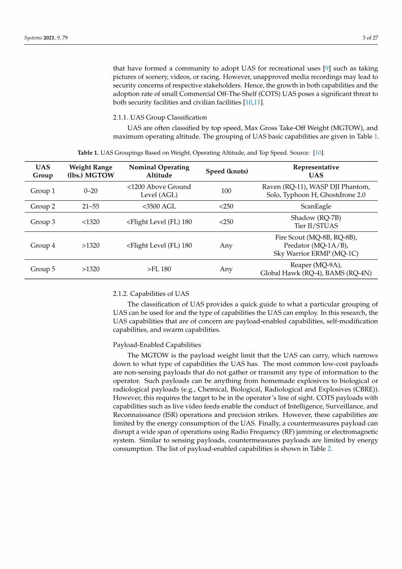
UAS are often classified by top speed, Max Gross Take-Off Weight (MGTOW), andmaximum operating altitude. The grouping of UAS basic capabilities are given in Table 1.
Table 1. UAS Groupings Based on Weight, Operating Altitude, and Top Speed. Source: [10].
UAS Weight Range Nominal Operating Speed (knots) RepresentativeGroup (lbs.) MGTOW Altitude UAS
Group 1 0–20 <1200 Above Ground 100 Raven (RQ-11), WASP DJI Phantom,Level (AGL) Solo, Typhoon H, Ghostdrone 2.0
Group 2 21–55 <3500 AGL <250 ScanEagle
Group 3 <1320 <Flight Level (FL) 180 <250 Shadow (RQ-7B)Tier II/STUAS
Group 4 >1320 <Flight Level (FL) 180 AnyFire Scout (MQ-8B, RQ-8B),
Predator (MQ-1A/B),Sky Warrior ERMP (MQ-1C)
Group 5 >1320 >FL 180 Any Reaper (MQ-9A),Global Hawk (RQ-4), BAMS (RQ-4N)
2.1.2. Capabilities of UAS
The classification of UAS provides a quick guide to what a particular grouping ofUAS can be used for and the type of capabilities the UAS can employ. In this research, theUAS capabilities that are of concern are payload-enabled capabilities, self-modificationcapabilities, and swarm capabilities.
Payload-Enabled Capabilities
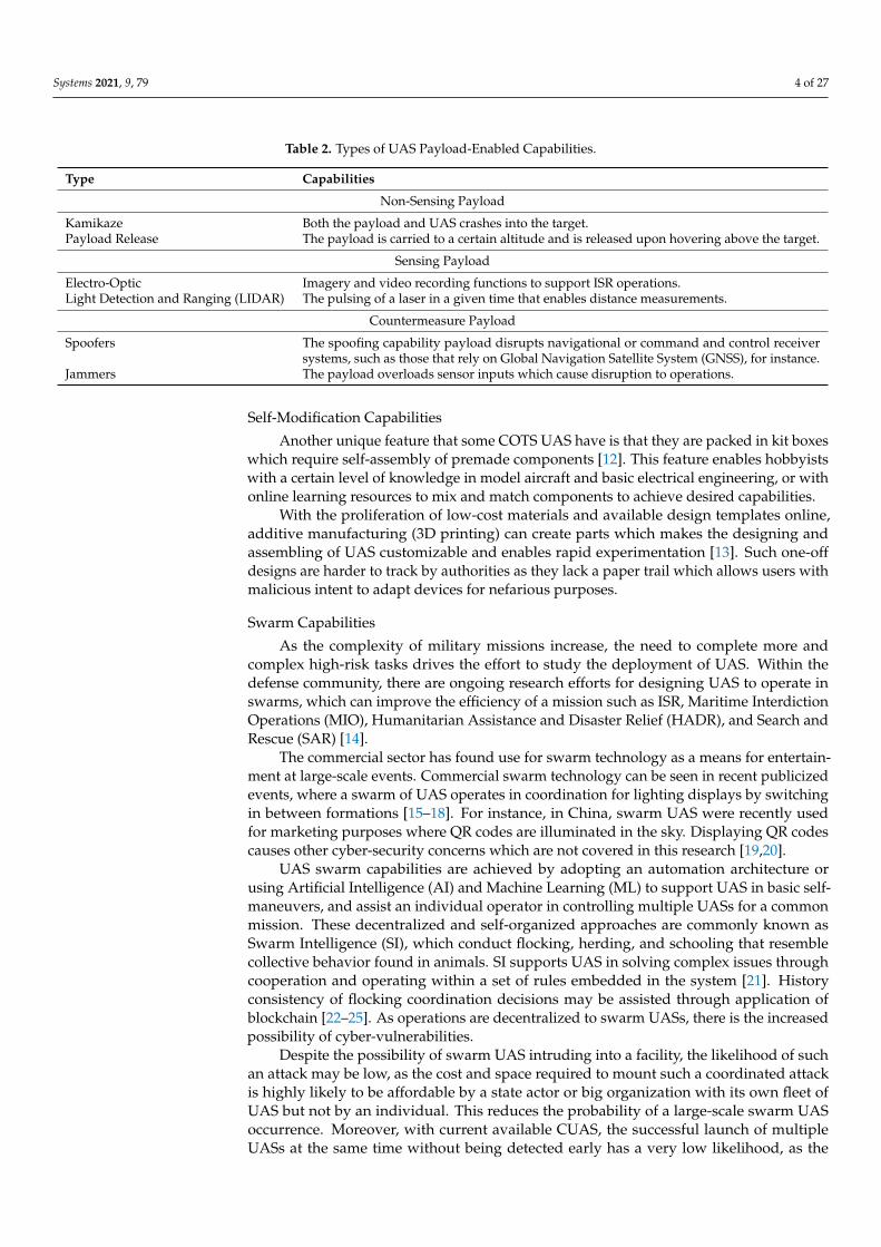
The MGTOW is the payload weight limit that the UAS can carry, which narrowsdown to what type of capabilities the UAS has. The most common low-cost payloadsare non-sensing payloads that do not gather or transmit any type of information to theoperator. Such payloads can be anything from homemade explosives to biological orradiological payloads (e.g., Chemical, Biological, Radiological and Explosives (CBRE)).However, this requires the target to be in the operator’s line of sight. COTS payloads withcapabilities such as live video feeds enable the conduct of Intelligence, Surveillance, andReconnaissance (ISR) operations and precision strikes. However, these capabilities arelimited by the energy consumption of the UAS. Finally, a countermeasures payload candisrupt a wide span of operations using Radio Frequency (RF) jamming or electromagneticsystem. Similar to sensing payloads, countermeasures payloads are limited by energyconsumption. The list of payload-enabled capabilities is shown in Table 2.
Systems 2021, 9, 79 4 of 27
Table 2. Types of UAS Payload-Enabled Capabilities.
Type Capabilities
Non-Sensing Payload
Kamikaze Both the payload and UAS crashes into the target.Payload Release The payload is carried to a certain altitude and is released upon hovering above the target.
Sensing Payload
Electro-Optic Imagery and video recording functions to support ISR operations.Light Detection and Ranging (LIDAR) The pulsing of a laser in a given time that enables distance measurements.
Countermeasure Payload
Spoofers The spoofing capability payload disrupts navigational or command and control receiversystems, such as those that rely on Global Navigation Satellite System (GNSS), for instance.
Jammers The payload overloads sensor inputs which cause disruption to operations.
Self-Modification Capabilities
Another unique feature that some COTS UAS have is that they are packed in kit boxeswhich require self-assembly of premade components [12]. This feature enables hobbyistswith a certain level of knowledge in model aircraft and basic electrical engineering, or withonline learning resources to mix and match components to achieve desired capabilities.
With the proliferation of low-cost materials and available design templates online,additive manufacturing (3D printing) can create parts which makes the designing andassembling of UAS customizable and enables rapid experimentation [13]. Such one-offdesigns are harder to track by authorities as they lack a paper trail which allows users withmalicious intent to adapt devices for nefarious purposes.
Swarm Capabilities
As the complexity of military missions increase, the need to complete more andcomplex high-risk tasks drives the effort to study the deployment of UAS. Within thedefense community, there are ongoing research efforts for designing UAS to operate inswarms, which can improve the efficiency of a mission such as ISR, Maritime InterdictionOperations (MIO), Humanitarian Assistance and Disaster Relief (HADR), and Search andRescue (SAR) [14].
The commercial sector has found use for swarm technology as a means for entertain-ment at large-scale events. Commercial swarm technology can be seen in recent publicizedevents, where a swarm of UAS operates in coordination for lighting displays by switchingin between formations [15–18]. For instance, in China, swarm UAS were recently usedfor marketing purposes where QR codes are illuminated in the sky. Displaying QR codescauses other cyber-security concerns which are not covered in this research [19,20].
UAS swarm capabilities are achieved by adopting an automation architecture orusing Artificial Intelligence (AI) and Machine Learning (ML) to support UAS in basic self-maneuvers, and assist an individual operator in controlling multiple UASs for a commonmission. These decentralized and self-organized approaches are commonly known asSwarm Intelligence (SI), which conduct flocking, herding, and schooling that resemblecollective behavior found in animals. SI supports UAS in solving complex issues throughcooperation and operating within a set of rules embedded in the system [21]. Historyconsistency of flocking coordination decisions may be assisted through application ofblockchain [22–25]. As operations are decentralized to swarm UASs, there is the increasedpossibility of cyber-vulnerabilities.
Despite the possibility of swarm UAS intruding into a facility, the likelihood of suchan attack may be low, as the cost and space required to mount such a coordinated attackis highly likely to be affordable by a state actor or big organization with its own fleet ofUAS but not by an individual. This reduces the probability of a large-scale swarm UASoccurrence. Moreover, with current available CUAS, the successful launch of multipleUASs at the same time without being detected early has a very low likelihood, as the
Systems 2021, 9, 79 5 of 27
signature created at the launch site will inevitably be high. However, the risk should notbe completely ruled out, as the fast growth in swarm technology could support future greyzone warfare in the event of rising tensions between nations.
The direct threat of concern to many facilities is small COTS UAS (Group 1 and 2)and modified UAS, as they are inexpensive, easily acquired, and are difficult to detect andintercept [26]. As the adoption of UAS by the public increases, there are increasing reportsof UAS intrusions and sightings which disrupt facility operations and cause monetarylosses, flights delays, and unnecessary risks (e.g., 2018 Gatwick drone incident and 2019Changi Airport drone incident [27,28]). A 2018 study by the CUAS capabilities analysisworking group established the probable nefarious uses of UAS by non-state actors is likelyto be for ISR, conveyance of contraband, kamikaze explosive attacks, and CBRE attacks.
2.2. Counter-Unmanned Aerial System
There currently is a wide span of CUAS solutions provided with a range of differentconfigurations that can be purchased as separate systems or suites of systems that can beadopted directly [29–31]. The concept of the system solution between different companiesis similar—namely the ability to detect and intercept UAS.
A variety of considerations influence the CUAS system configuration and performancesuch as the level of facility security required, the expected time needed from initial detectionUAS intrusion until interdiction of the UAS occurs, and the type of deployed interceptorsystem (e.g., kinetic, RF jamming, energy pulse, etc.). Given the need in flexibility of systemconfigurations, the cost of deploying CUAS is relatively high for a sophisticated solution, asit is a complex system of systems that requires detailed study of the environment in which itoperates (e.g., nearby tall buildings, terrain, weather, other environmental behavior factors,etc.) to mitigate possible interference that may cause poor system performance.
2.2.1. System Kill Chain
The kill chain model of CUAS is similar to the generic military application of Find,Fix, Track, Target, Engage, Assess (F2T2EA), and the definition of each process is given inTable 3.
Table 3. Definitions of the Find, Fix, Track, Target, Engage, Assess (F2T2EA) Kill Chain. Adaptedfrom [32].
Kill Chain Definition
Find Identify a target. Find a target within surveillance or reconnaissance data orvia intelligence means.
Fix Fix the target’s location. Obtain specific coordinates for the target either fromexisting data or by collecting additional data.
Track Monitor the target’s movement. Keep track of the target until either a decisionis made not to engage the target, or the target is successfully engaged.
TargetSelect an appropriate weapon or asset to use on the target to create desiredeffects. Apply command and control capabilities to assess the value of thetarget and the availability of appropriate weapons to engage it.
Engage Apply the weapon to the target.
Assess Evaluate effects of the attack, including any intelligence gathered at thelocation.
With an understanding of the F2T2EA kill chain, we suggest that the CUAS kill chaincan then be simplified for the purposes of this research from F2T2EA to only detection andinterception. The detection consists of find, fix, track; and the remaining processes fallunder interception. This simplification helps with the association of the kill chain processwith physical subsystem capabilities and key performance metrics that will be discussed inSections 2.2.2 and 3.
Systems 2021, 9, 79 6 of 27
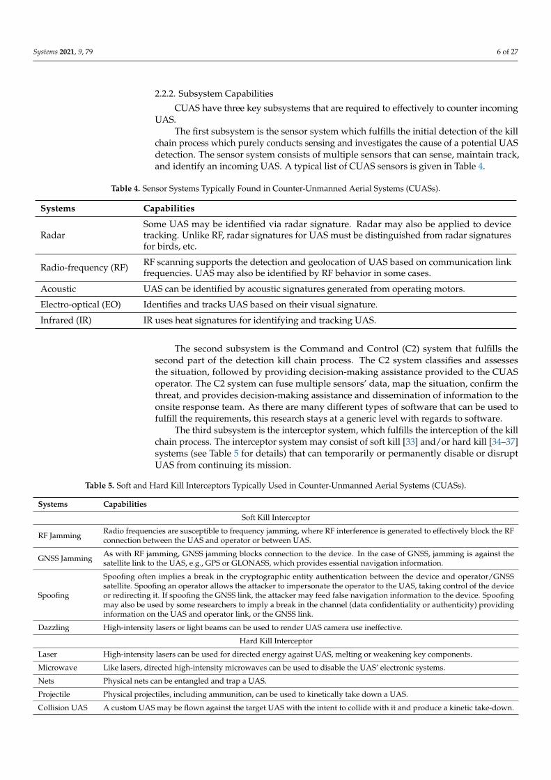
2.2.2. Subsystem Capabilities
CUAS have three key subsystems that are required to effectively to counter incomingUAS.
The first subsystem is the sensor system which fulfills the initial detection of the killchain process which purely conducts sensing and investigates the cause of a potential UASdetection. The sensor system consists of multiple sensors that can sense, maintain track,and identify an incoming UAS. A typical list of CUAS sensors is given in Table 4.
Table 4. Sensor Systems Typically Found in Counter-Unmanned Aerial Systems (CUASs).
Systems Capabilities
RadarSome UAS may be identified via radar signature. Radar may also be applied to devicetracking. Unlike RF, radar signatures for UAS must be distinguished from radar signaturesfor birds, etc.
Radio-frequency (RF) RF scanning supports the detection and geolocation of UAS based on communication linkfrequencies. UAS may also be identified by RF behavior in some cases.
Acoustic UAS can be identified by acoustic signatures generated from operating motors.
Electro-optical (EO) Identifies and tracks UAS based on their visual signature.
Infrared (IR) IR uses heat signatures for identifying and tracking UAS.
The second subsystem is the Command and Control (C2) system that fulfills thesecond part of the detection kill chain process. The C2 system classifies and assessesthe situation, followed by providing decision-making assistance provided to the CUASoperator. The C2 system can fuse multiple sensors’ data, map the situation, confirm thethreat, and provides decision-making assistance and dissemination of information to theonsite response team. As there are many different types of software that can be used tofulfill the requirements, this research stays at a generic level with regards to software.
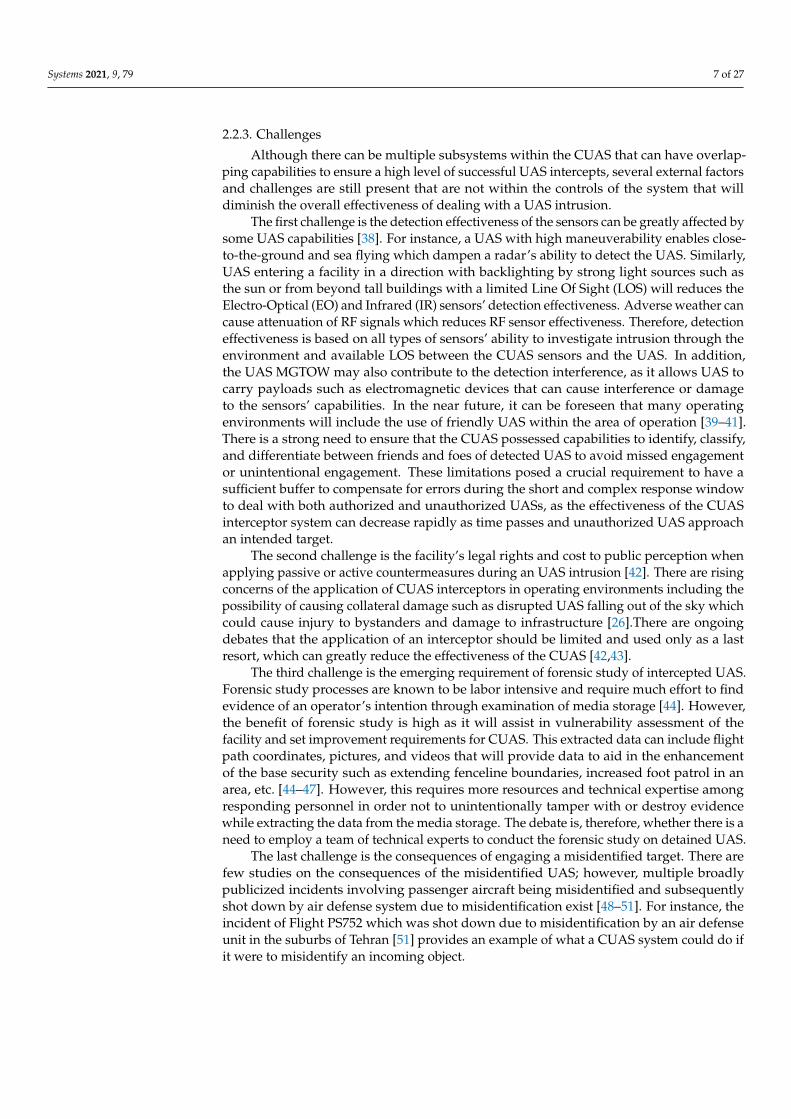
The third subsystem is the interceptor system, which fulfills the interception of the killchain process. The interceptor system may consist of soft kill [33] and/or hard kill [34–37]systems (see Table 5 for details) that can temporarily or permanently disable or disruptUAS from continuing its mission.
Table 5. Soft and Hard Kill Interceptors Typically Used in Counter-Unmanned Aerial Systems (CUASs).
Systems Capabilities
Soft Kill Interceptor
RF Jamming Radio frequencies are susceptible to frequency jamming, where RF interference is generated to effectively block the RFconnection between the UAS and operator or between UAS.
GNSS Jamming As with RF jamming, GNSS jamming blocks connection to the device. In the case of GNSS, jamming is against thesatellite link to the UAS, e.g., GPS or GLONASS, which provides essential navigation information.
Spoofing
Spoofing often implies a break in the cryptographic entity authentication between the device and operator/GNSSsatellite. Spoofing an operator allows the attacker to impersonate the operator to the UAS, taking control of the deviceor redirecting it. If spoofing the GNSS link, the attacker may feed false navigation information to the device. Spoofingmay also be used by some researchers to imply a break in the channel (data confidentiality or authenticity) providinginformation on the UAS and operator link, or the GNSS link.
Dazzling High-intensity lasers or light beams can be used to render UAS camera use ineffective.
Hard Kill Interceptor
Laser High-intensity lasers can be used for directed energy against UAS, melting or weakening key components.
Microwave Like lasers, directed high-intensity microwaves can be used to disable the UAS’ electronic systems.
Nets Physical nets can be entangled and trap a UAS.
Projectile Physical projectiles, including ammunition, can be used to kinetically take down a UAS.
Collision UAS A custom UAS may be flown against the target UAS with the intent to collide with it and produce a kinetic take-down.
Systems 2021, 9, 79 7 of 27
2.2.3. Challenges
Although there can be multiple subsystems within the CUAS that can have overlap-ping capabilities to ensure a high level of successful UAS intercepts, several external factorsand challenges are still present that are not within the controls of the system that willdiminish the overall effectiveness of dealing with a UAS intrusion.
The first challenge is the detection effectiveness of the sensors can be greatly affected bysome UAS capabilities [38]. For instance, a UAS with high maneuverability enables close-to-the-ground and sea flying which dampen a radar’s ability to detect the UAS. Similarly,UAS entering a facility in a direction with backlighting by strong light sources such asthe sun or from beyond tall buildings with a limited Line Of Sight (LOS) will reduces theElectro-Optical (EO) and Infrared (IR) sensors’ detection effectiveness. Adverse weather cancause attenuation of RF signals which reduces RF sensor effectiveness. Therefore, detectioneffectiveness is based on all types of sensors’ ability to investigate intrusion through theenvironment and available LOS between the CUAS sensors and the UAS. In addition,the UAS MGTOW may also contribute to the detection interference, as it allows UAS tocarry payloads such as electromagnetic devices that can cause interference or damageto the sensors’ capabilities. In the near future, it can be foreseen that many operatingenvironments will include the use of friendly UAS within the area of operation [39–41].There is a strong need to ensure that the CUAS possessed capabilities to identify, classify,and differentiate between friends and foes of detected UAS to avoid missed engagementor unintentional engagement. These limitations posed a crucial requirement to have asufficient buffer to compensate for errors during the short and complex response windowto deal with both authorized and unauthorized UASs, as the effectiveness of the CUASinterceptor system can decrease rapidly as time passes and unauthorized UAS approachan intended target.
The second challenge is the facility’s legal rights and cost to public perception whenapplying passive or active countermeasures during an UAS intrusion [42]. There are risingconcerns of the application of CUAS interceptors in operating environments including thepossibility of causing collateral damage such as disrupted UAS falling out of the sky whichcould cause injury to bystanders and damage to infrastructure [26].There are ongoingdebates that the application of an interceptor should be limited and used only as a lastresort, which can greatly reduce the effectiveness of the CUAS [42,43].
The third challenge is the emerging requirement of forensic study of intercepted UAS.Forensic study processes are known to be labor intensive and require much effort to findevidence of an operator’s intention through examination of media storage [44]. However,the benefit of forensic study is high as it will assist in vulnerability assessment of thefacility and set improvement requirements for CUAS. This extracted data can include flightpath coordinates, pictures, and videos that will provide data to aid in the enhancementof the base security such as extending fenceline boundaries, increased foot patrol in anarea, etc. [44–47]. However, this requires more resources and technical expertise amongresponding personnel in order not to unintentionally tamper with or destroy evidencewhile extracting the data from the media storage. The debate is, therefore, whether there is aneed to employ a team of technical experts to conduct the forensic study on detained UAS.
The last challenge is the consequences of engaging a misidentified target. There arefew studies on the consequences of the misidentified UAS; however, multiple broadlypublicized incidents involving passenger aircraft being misidentified and subsequentlyshot down by air defense system due to misidentification exist [48–51]. For instance, theincident of Flight PS752 which was shot down due to misidentification by an air defenseunit in the suburbs of Tehran [51] provides an example of what a CUAS system could do ifit were to misidentify an incoming object.
Systems 2021, 9, 79 8 of 27
2.3. Existing Methods of Developing and Deploying CUAS
Several methods exist to develop and deploy CUAS and similar related physicalprotection systems such as Garcia’s physical protection design and evaluation methodwhere the method begins with the determination of physical protection system objectiveswhich characterizes the physical facility, defines threat, and develops target identification.Next, the design of the system is split into three broad categories of detection, delay, andresponse. The analysis is then carried out on the system design to determine whetherthe system design has met the requirements, and lastly, to be output as a final design oriterated back to the redesign loop.
Another related method is the National Institute of Standards and Technology (NIST)risk management framework, which provides a generic process that can be applied toany type of system [52]. The processes are prepare, categorize, select, implement, assess,authorize and monitor. Each process is required to meet a certain objective which guidesan organization in adopting a more comprehensive risk management plan. The preparestep identifies the key risk management roles and established strategy that can be adoptedorganization-wide. The categorize step, ranks the risk based on the impact level andappoints an appropriate approving authority. Then the selection of control measures to beallocated to specific system components is made. The implement step applies the controlsfor the system and organization. The next step, assessment, assesses if the controls havemet the intended outcome. The approving authority then reviews the assessment to see ifthe risk management plan is acceptable. Lastly, the continuous monitoring of the risk onthe control implementation to allow timely review or intervention.
In general, the concepts and principles of the two above discussed methods are rele-vant and applicable for adoption in conducting analysis on a CUAS system. Although theydo not directly address the need for a CUAS design method, they do provide inspiration tothis research.
3. Methodology
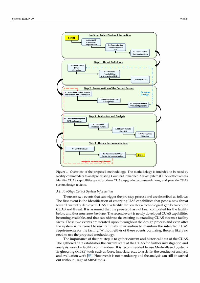
Rapidly developing UAS technology has caused disruption to the design and im-plementation of CUAS systems. Due to this, there is often scope creep and/or new re-quirements introduced late in the CUAS system design cycle which can lead to higheroverall project cost or a failed CUAS deployment. To successfully deliver CUAS solutionsto facilities, there is a need to develop a cost effective and comprehensive system analysismethod that can ensure the CUAS stays relevant against new emerging UAS technologyand threats. This section proposes a system perspective analysis method that can guide afacility commander in developing new CUAS capabilities and augmenting existing CUAS.The proposed methodology provides insights for how the CUAS system can be optimizedto achieve required system effectiveness and allow timely intervention to propose CUASsystem redesign solutions. The proposed methodology illustrated in Figure 1 is not de-pendent on any specific CUAS technology and can be adopted by any facility to conductanalysis and evaluation of potential and existing CUAS systems.
Systems 2021, 9, 79 9 of 27
Figure 1. Overview of the proposed methodology. The methodology is intended to be used byfacility commanders to analyze existing Counter-Unmanned Aerial System (CUAS) effectiveness,identify CUAS capabilities gaps, produce CUAS upgrade recommendations, and provide CUASsystem design reviews.
3.1. Pre-Step: Collect System Information
There are two events that can trigger the pre-step process and are described as follows:The first event is the identification of emerging UAS capabilities that pose a new threattoward currently deployed CUAS at a facility that creates a technological gap between theCUAS and threat. It is assumed that the pre-step has not been completed for the facilitybefore and thus must now be done. The second event is newly developed CUAS capabilitiesbecoming available, and that can address the existing outstanding CUAS threats a facilityfaces. These two events are iterated upon throughout the design process and even afterthe system is delivered to ensure timely intervention to maintain the intended CUASrequirements for the facility. Without either of these events occurring, there is likely noneed to use the proposed methodology.
The importance of the pre-step is to gather current and historical data of the CUAS.The gathered data establishes the current state of the CUAS for further investigation andanalysis work by facility commanders. It is recommended to use Model-Based SystemsEngineering (MBSE) tools such as Core, Innoslate, etc., to assist in the conduct of analysisand evaluation work [53]. However, it is not mandatory, and the analysis can still be carriedout without usage of MBSE tools.
Systems 2021, 9, 79 10 of 27
3.1.1. Step 0.1: Establish Stakeholders’ Requirements
The initial data required from the stakeholders are the (1) daily activities within thefacility, (2) expected environmental conditions, and (3) facility security requirements.
The daily activities data can be human or asset (e.g., planes, cargo vessels, etc.) trafficflow, routine operations, and possible ad-hoc operations that need to be carried out by therespective stakeholders. This can provide a baseline of types of daily activities that will bein operation alongside the CUAS at the facility.
Next, to understand the expected environmental conditions that the system needsto operate in, there is a need to gather facility blueprints, the maximum and minimumboundaries of the facility (some facilities have zones of protection that extend beyond thesite boundary), conduct a direct line-of-sight study, identify possible wildlife activity, andcollect historical weather condition data. This effort identifies the environment’s “noise”that could interfere CUAS system performance.
Lastly, the stakeholders are to determine their expectations of CUAS security require-ments. This requires the stakeholders to list their critical assets with the expected level ofprotection and security classification of the assets.
The objective in this step is to determine the expected CUAS operation conditionsand acceptable security level so that the system can be configured to meet all stakeholderrequirements.
3.1.2. Step 0.2: Review Existing Risk Management Plan
In this step, there is a need to understand the current risk management plan that is inplace to address the inherent vulnerability of the existing CUAS. The inherent vulnerabilitycan be associated with three parts: the first is physical system failures such as electricalfaults, inclement weather, fires, and accidents. The second is potential infrastructuredamages and personnel injury caused by falling interdicted UAS. Lastly, the risks posedby cyber-security may have catastrophic outcomes such as if an attacker successfully gainscontrol over either the CUAS’s detection or interception systems.
The review of the existing risk management plan is to determine whether there is anyimpact on existing vulnerabilities introduced by a new CUAS design solution. Ideally, anew CUAS design solution should cut down on the number of risks that the existing riskmanagement plan must address. Otherwise, there is a need to identify new mitigationmeasures that requires and possibly overlaps with the existing risk management plan.
The objective in this step is to allow the facility commander to have an informedconsideration of the impact to daily operations on CUAS activities. This will be achievedby garnering collective agreement from the various stakeholders of the mitigation plansthat will be in place to manage the identified inherent risks [54].
3.1.3. Step 0.3: Gather System Operator Feedback
The last step of pre-step is to gather feedback from the personnel who interact with theCUAS. To achieve high overall CUAS effectiveness, it is good practice to include currentoperators or personnel that interact with the CUAS during design reviews, as the operatorsand personnel may uncover limiting constraints or beneficial concepts which otherwisewould not be recognized.
These data can then support Human Factors Engineering (HFE) design efforts thatimprove the interaction between the operator and the system [55]. This interaction im-provement implies a better response time and reduction in human errors, as the interactionis more intuitive for the operator, which also increases the overall system effectiveness.
3.2. Step 1: Threat Definitions
In Step 1, the objective is to assemble current technical specifications of the Group 1and 2 UAS. A static list of technical specifications cannot be used because UAS develop-ment is constantly advancing which translates into new capabilities that are frequentlyemerging [56].

Systems 2021, 9, 79 11 of 27
3.2.1. Step 1.1: Establish New Threat Information
As discussed in Section 2.1, the facility commander must understand UAS capabilitiesthat are of concern to the facility. Such concerns can be payload-enabled capabilities, self-modification capabilities, and swarm capabilities, among others. For instance, if any of theabove capabilities have been made available to COTS UAS, the facility commander shouldreview the existing CUAS and determine whether the current CUAS design solution is stillrelevant to manage the new threat. Hence, the facility commander requires both UAS andCUAS capability parameters to be collected to conduct the analysis.
3.2.2. Step 1.2: Determine Potential CUAS System Vulnerabilities
To determine potential CUAS system vulnerabilities, an understanding of baselinesystem performance must be developed. We recommend that the CUAS system’s baselineperformance be established through the listing of expected daily operation and be basedon possible UAS intrusion scenarios that may occur to the facility. Furthermore, potentialfuture and as yet unobserved scenarios should also be considered. The subsequent CUASevaluation can then harness the insights on vulnerabilities of the CUAS.
Given the identified vulnerabilities and data developed in the previous steps, it isnow possible to provide tangible measurement of CUAS effectiveness. We derive genericmathematical representation of the probability of CUAS effectiveness from Kouhestani [57].CUAS effectiveness can be determined by Equation (1), which is the product of probabilityof detection and probability of interception. The breakdown of the two sub-functions’equations is explained in subsequent sections.
P(E f f ectiveness) = P(Detection)× P(Interception) (1)
The probability of detection functions refers to the probability of the sensor’s chancesto detect the presence of a UAS. This includes the element of accurate identification andclassification of UAS, which can also be implied as the false alarm rate. The three sub-performance metrics of detection effectiveness in terms of probability are sense (P(Sense)),track (P(Track)), and data transmission (P(Transmission)). The relationship between eachof the sub-performance metrics and their definition are given in Equation (2) and Table 6respectively.
P(Detection) = P(Sense)× P(Track)× P(Transmission) (2)
Table 6. Performance Metrics and Definitions of Detection for Counter-Unmanned Aerial Systems (CUASs).
Performance Metrics Definitions
Detection Effectiveness
Probability of SenseThe probability of the sensors able to detect the presence of UAS and initiate alarm.The higher probability of sense will increase the CUAS success rate of accuratelydetecting UAS.
Probability of Track The probability of accurate track of UAS’s geolocation. The lesser track drop willincrease the CUAS accuracy of acquiring UAS position.
Probability of TransmissionThe probability of successful data transfer ring over a period of time to a responseteam and/or interceptor subsystem. The data may contain information such as UASmodels and coordinates necessary for action against the UAS.
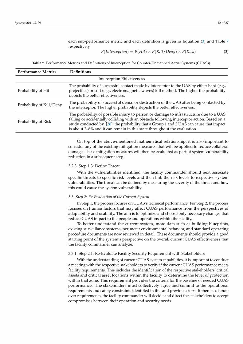
The probability of interception (P(Interception)) refers to the probability of the CUASsystem being able to deny or disable a UAS from continuing its intended mission. Thesub-performance metrics that make up the interception effectiveness in terms of probabilityare hit (P(Hit)), kill/deny (P(Kill/Deny), and risk ((P(Risk)). The relationship between
Systems 2021, 9, 79 12 of 27
each sub-performance metric and each definition is given in Equation (3) and Table 7respectively.
P(Interception) = P(Hit)× P(Kill/Deny)× P(Risk) (3)
Table 7. Performance Metrics and Definitions of Interception for Counter-Unmanned Aerial Systems (CUASs).
Performance Metrics Definitions
Interception Effectiveness
Probability of HitThe probability of successful contact made by interceptor to the UAS by either hard (e.g.,projectiles) or soft (e.g., electromagnetic waves) kill method. The higher the probabilitydepicts the better effectiveness.
Probability of Kill/Deny The probability of successful denial or destruction of the UAS after being contacted bythe interceptor. The higher probability depicts the better effectiveness.
Probability of Risk
The probability of possible injury to person or damage to infrastructure due to a UASfalling or accidentally colliding with an obstacle following interceptor action. Based on astudy conducted by [26], the probability that a Group 1 and 2 UAS can cause that impactis about 2–6% and it can remain in this state throughout the evaluation.
On top of the above-mentioned mathematical relationship, it is also important toconsider any of the existing mitigation measures that will be applied to reduce collateraldamage. These mitigation measures will then be evaluated as part of system vulnerabilityreduction in a subsequent step.
3.2.3. Step 1.3: Define Threat
With the vulnerabilities identified, the facility commander should next associatespecific threats to specific risk levels and then link the risk levels to respective systemvulnerabilities. The threat can be defined by measuring the severity of the threat and howthis could cause the system vulnerability.
3.3. Step 2: Re-Evaluation of the Current System
In Step 1, the process focuses on CUAS’s technical performance. For Step 2, the processfocuses on human factors that may affect CUAS performance from the perspectives ofadaptability and usability. The aim is to optimize and choose only necessary changes thatreduce CUAS impact to the people and operations within the facility.
To better understand the current system, more data such as building blueprints,existing surveillance systems, perimeter environmental behavior, and standard operatingprocedure documents are now reviewed in detail. These documents should provide a goodstarting point of the system’s perspective on the overall current CUAS effectiveness thatthe facility commander can analyze.
3.3.1. Step 2.1: Re-Evaluate Facility Security Requirement with Stakeholders
With the understanding of current CUAS system capabilities, it is important to conducta meeting with the respective stakeholders to verify if the current CUAS performance meetsfacility requirements. This includes the identification of the respective stakeholders’ criticalassets and critical asset locations within the facility to determine the level of protectionwithin that zone. This requirement provides the criteria for the baseline of needed CUASperformance. The stakeholders must collectively agree and commit to the operationalrequirements and safety constraints identified in this and previous steps. If there is disputeover requirements, the facility commander will decide and direct the stakeholders to acceptcompromises between their operation and security needs.
Systems 2021, 9, 79 13 of 27
3.3.2. Step 2.2: Develop Operational Concept View
At this point, a variety of Operational Viewpoint-1 (OV-1)s and accompanying systemarchitectural products should be developed to demonstrate multiple potential CUASsystems configurations. These CUAS configurations will be used in subsequent steps tocompare against requirements and eventually either determine that the current CUAS issufficient or that the CUAS should be either upgraded or replaced.
We suggest that the OV-1 view is particularly important to develop because it allowsthe facility commander and stakeholders to have a visualization of the CUAS systemperspective. This helps to clarify interactions or identify missing interactions betweenportions of the base and surrounding community and the CUAS. The case study in asubsequent section provides an example of OV-1.
3.3.3. Step 2.3: Analyze Candidate CUAS Configurations
Now that several candidate CUAS configurations have been developed, a trade-offanalysis of requirements can be conducted. We recommend the Pugh Matrix approachbecause it provides a method to do scoring in terms of positive or negative impact onspecific requirements based on the facility commander’s best intuition according to theavailable data [58].
The Pugh Matrix analysis results can identify which CUAS candidates’ configurationis the most preferred. The CUAS configurations are ranked based on the stakeholders’requirement and translated down as a decision to improve an existing CUAS (or build anew CUAS if none already exists) or remain with the existing CUAS.
If the candidate’ CUAS configuration solution benefit is lower or matches the currentCUAS, the recommendation is that no change to the current CUAS be undertaken. In thiscase, return to Step 1 for continued monitoring of the situation for future emerging UASthreats. Otherwise, if there are technological gaps found in the capabilities of the existingCUAS against UAS, proceed to Step 3.
3.4. Step 3: Evaluation and Analysis
In Step 3, a more in-depth evaluation and analysis is conducted to assess the effective-ness of the proposed CUAS solution from Step 2.3. This includes generating the workflowof the proposed solution and using MBSE software to conduct simulation work.
3.4.1. Step 3.1: Simulate the Proposed CUAS Configuration
In this step, MBSE software is used to conduct detailed evaluations of the proposedCUAS configuration. In the case study presented in this research, CORE software is usedto conduct the simulation of the CUAS’s functions which allows the facility commander toassess the feasibility of the function’s interactions. However, many other MBSE softwarepackages are available and have similar functionality.
3.4.2. Step 3.2: Determine Dominant Factors
The objective in this step is to identify the dominant factors that have the most impacton overall CUAS performance through simulating the down-selected CUAS configurationthat was identified in Step 3.1. This approach reduces cost and time required to assess thenew CUAS configuration that may not otherwise have sufficient real-world data pointsfor detailed analysis. Another benefit of conducting simulations is that simulations canexplore high-risk scenarios that involve personnel, hazardous payloads, and other threatswhich would be dangerous to be conducted physically. We suggest conducting a Design OfExperiment (DOE) as part of this step using software such as Minitab, ExtendSim, or COREto generate time-based simulations that can produce results such as outcome probabilitydistributions, identify delays and bottlenecks in the CUAS response, and implementprobabilistic decision-making which can improve realism in the simulations [10,59].
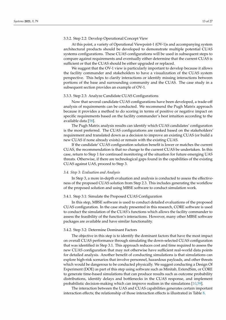
The interaction between the UAS and CUAS capabilities generates certain importantinteraction effects; the relationship of those interaction effects is illustrated in Table 8.
Systems 2021, 9, 79 14 of 27
Table 8. Effects of the Unmanned Aerial System (UAS) and Counter-Unmanned Aerial System (CUAS) CapabilitiesInteractions.
System Capability Parameter Effects Rationale
UAS Maximum Range Detection RangeTo achieve earlier detection possible, the detectioncoverage should include the UAS maximum distanceoutwards starting from the facility outer perimeter.
UAS Maximum Speed Response Time Required to intercept before the UAS achieves theobjective.
CUAS Identification and Clas-sification Time Reaction Time
This duration must be much shorter and within theresponse time. This could also be used to justify if thisprocess should be managed by human-in-the-loop orfull automation.
CUAS Tracking Capacity Software Algorithm andSensors Capabilities
This will determine the ability of CUAS to deal with aswarm of UAS.
CUAS Maximum InterceptorRange Engagement Window It will be ideal for the interceptor to be able to engage
as soon as possible.
3.4.3. Step 3.3: Identify Risks to the CUAS
In this step, risks to the CUAS are identified to allow for mitigation strategies to bedeveloped in the subsequent step. In this context, we are interested in risk of the CUASnot performing as intended.
CUAS system risks can be caused by limitations that are inherent to some CUASsubsystems such as sensors and interceptors requiring line of sight with the UAS, no sunglare, and other related interferences. The CUAS is designed to be a system of systemwhich aims to address the inherent individual sensors’ and interceptors’ vulnerabilities toeliminate such single points of failure. Additional risks may be present such as bypassing(e.g., through blind spots, via saturating or overloading a sensor, etc.) or spoofing sensors.Interceptors can be vulnerable if unable to activate in a timely manner which can lead tomissed UAS engagement opportunities. Additionally, the risks to facility personnel andnearby communities caused by CUAS must be considered. For example, an adversary’sUAS that loses control due to CUAS interception may fall or crash into nearby communities.
We suggest identifying and categorizing the risk level of the above-mentioned risksinto high, moderate and low risk categories based on the severity of each risk outcome.We define high risk as the possibility to cause significant damages or severe degradationof performance to the CUAS and/or facility and/or surrounding community, moderaterisk as the possibility to cause moderate damages or degradation of performance to theCUAS and/or facility and/or surrounding community, and low risk as the potential tocause minor damage or degradation to the CUAS and/or facility and/or surroundingcommunity.
3.4.4. Step 3.4: Develop Risk Mitigation
Next, risk mitigation plans for each identified risk can be developed.The mitigation plans’ aims are to increase the probability of CUAS success and reduce
potential collateral damage. We suggest that this can be achieved through a review of policy,practices, and procedures associated with the CUAS. To reduce CUAS system failure, theemphasis here is to develop and implement controls over the risk. This can be done bystrengthening the identified weak points of the system or accepting the risk and creatinglayers of processes to neutralize the risk if the CUAS system cannot be strengthened.Although there are a variety of mitigation strategies discussed below, we assert that themain consideration for risk mitigation should be to provide ample time for the CUASsystem to react safely to UAS intrusion that ensures the safety of people operating withinthe vicinity. We assert that this is a conservative and safer approach than others.
Systems 2021, 9, 79 15 of 27
The first mitigation strategy is to achieve early detection to increase CUAS engage-ment window duration. Detection coverage should be as far out as can be reasonablyaccommodated from the facility. The probability of successful detection can be furtherincreased by eliminating detection blind spots and reducing false alarm rates. If there isline-of-sight blockage by tall buildings or trees, this can be mitigated through employingpatrols to cover blind spots, pruning vegetation, or establishing satellite sensor locationsatop the tall buildings that otherwise would block CUAS sensors. This also involves addinglayers of procedures and a revamp of policy to allow installation of sensors on buildingsthat may not be controlled by the facility. To reduce the false alarm rate, we recommend themitigation efforts include employing environmental studies as discussed in previous stepsto understand the visibility conditions throughout different periods of the day such aspossible sun glare during sunrise and sunset, reduced visibility during inclement weather,and blockages by wildlife activities.
The second mitigation strategy is to have interceptors that are effective and will notcause disruption to facility operations or neighboring communities. The time taken to reactand neutralize a UAS intrusion is expected to be swift, and the result is expected to bedecisive. This mitigation strategy aims to intercept the UAS before it enters the facility orat least prior to encountering sensitive areas of the facility. We suggest employing multiplelayers of interceptors to allow CUAS engagement at different distances and with differentinterception methods to eliminate the possibility of a single point of failure.
3.5. Step 4: Design Recommendations
In the final step, the stakeholders collectively make a decision on CUAS upgrades andimplementation.
3.5.1. Step 4.1: Verify TRL Level
In this step, checks must be performed to ensure that selected CUAS technologiesand configurations meet appropriate Technology Readiness Level (TRL) levels. We advo-cate using Kouhestani’s CUAS TRL levels where Level 1 is scenario-based testing (e.g.,“red-teaming” [60–62]), Level 2 is exploratory testing, Level 3 is baseline characterizationtesting, Level 4 is performance testing (statistical confidence levels), Level 5 is degra-dation/vulnerability testing, and Post-Install is certification and periodic performancetesting [57]. Please note that Kouhestani’s TRL is significantly different than other TRLs.We prefer Kouhestani’s TRL levels over other approaches to TRL because it focuses onelements that are more apropos to the rapid development of technologies associated withCUAS and UAS. Kouhestani’s TRL is specifically designed for UAS and CUAS whileother methods such as the National Aeronautics and Space Administration (NASA) TRLare more suited for aerospace purposes etc. However, a practitioner using this method mayadapt the method to their own preferred TRL method. For the purposes of this research, wesuggest that TRL Level 1 is the minimum level that any specific system or subsystem mustbe at within the CUAS for consideration. We recommend not evaluating TRL earlier in themethodology beyond ensuring that CUAS technologies are on track to be at TRL Level 1by the time Step 4 is reached because of the rapid development of CUAS technology tokeep pace with the rapid development of UAS technology. If a facility was constrainedto only evaluate TRL Level 5, then in our opinion the facility would have little hope ofever countering the latest UAS threats and instead would be protected against old andoutmoded UAS threats.
After confirming the TRL levels, the results can be bundled into a package for stake-holder review.
3.5.2. Step 4.2: Recommended CUAS Design for Implementation
In this step, the stakeholders review all CUAS information compiled and developedover the previous steps. Stakeholders review the CUAS information to ensure that allrequirements are met satisfactorily. In the event that any requirements are not met, the
Systems 2021, 9, 79 16 of 27
stakeholders must either accept that some requirements will not be met or the CUAS designneeds to be iterated upon to meet requirements. If the CUAS does not meet requirements,the method returns to Step 2 and iterates until a suitable design solution is found or thestakeholders accept the CUAS limitations.
If the CUAS meets all requirements, the facility commander can proceed with im-plementing CUAS capability upgrades or deploying an entirely new CUAS dependingupon the situation. In parallel, the method iterates back to Step 2 to continuously monitoremerging new UAS and CUAS technologies and capabilities that can pose threats andsolutions to the facility. The proposed method never truly ends because the threat posedby new UAS innovations is ever evolving.
4. Case Study
This section demonstrates the usability of the proposed methodology applied to ahypothetical airport and CUAS in a dense urban area in a tropical environment. Althoughthe case study’s hypothetical airport and environment may bear a passing resemblanceto some airports, the details have been intentionally changed to retain realism but ensurethat no unintended disclosure of sensitive information could occur as a result of this article.The case study assumes that a CUAS is already in operation and the expected threat isfrom hobby UAS that are COTS systems. The analysis provides evidence to determine ifemerging UAS capabilities require an upgrade to the existing CUAS capability. In this case,study we use the MBSE software CORE to illustrate the proposed methodology.
4.1. Pre-Step: Collect System Information4.1.1. Step 0.1: Establish Stakeholders’ Requirements
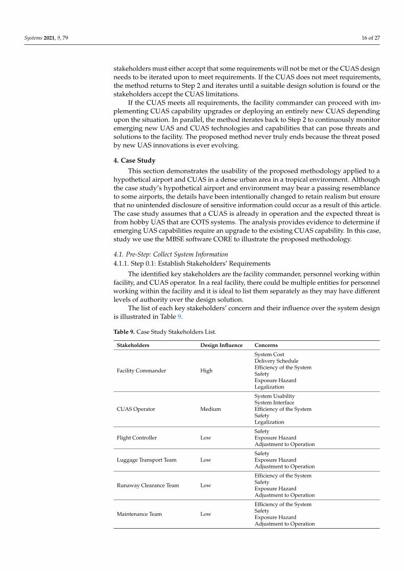
The identified key stakeholders are the facility commander, personnel working withinfacility, and CUAS operator. In a real facility, there could be multiple entities for personnelworking within the facility and it is ideal to list them separately as they may have differentlevels of authority over the design solution.
The list of each key stakeholders’ concern and their influence over the system designis illustrated in Table 9.
Table 9. Case Study Stakeholders List.
Stakeholders Design Influence Concerns
Facility Commander High
System CostDelivery ScheduleEfficiency of the SystemSafetyExposure HazardLegalization
CUAS Operator Medium
System UsabilitySystem InterfaceEfficiency of the SystemSafetyLegalization
Flight Controller LowSafetyExposure HazardAdjustment to Operation
Luggage Transport Team LowSafetyExposure HazardAdjustment to Operation
Runaway Clearance Team Low
Efficiency of the SystemSafetyExposure HazardAdjustment to Operation
Maintenance Team Low
Efficiency of the SystemSafetyExposure HazardAdjustment to Operation
Systems 2021, 9, 79 17 of 27
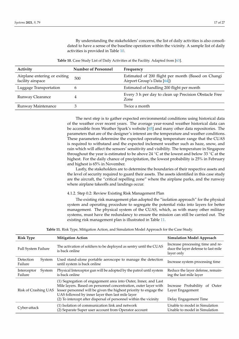
By understanding the stakeholders’ concerns, the list of daily activities is also consoli-dated to have a sense of the baseline operation within the vicinity. A sample list of dailyactivities is provided in Table 10.
Table 10. Case Study List of Daily Activities at the Facility. Adapted from [63].
Activity Number of Personnel Frequency
Airplane entering or exitingfacility airspace 500 Estimated of 200 flight per month (Based on Changi
Airport Group’s Data [64])
Luggage Transportation 6 Estimated of handling 200 flight per month
Runway Clearance 4 Every 3 h per day to clean up Precision Obstacle FreeZone
Runway Maintenance 3 Twice a month
The next step is to gather expected environmental conditions using historical dataof the weather over recent years. The average year-round weather historical data canbe accessible from Weather Spark’s website [65] and many other data repositories. Theparameters that are of the designer’s interest are the temperature and weather conditions.These parameters determine the expected operating temperature range that the CUASis required to withstand and the expected inclement weather such as haze, snow, andrain which will affect the sensors’ sensitivity and visibility. The temperature in Singaporethroughout the year is estimated to be above 24 ◦C at the lowest and below 33 ◦C at thehighest. For the daily chance of precipitation, the lowest probability is 25% in Februaryand highest is 65% in November.
Lastly, the stakeholders are to determine the boundaries of their respective assets andthe level of security required to guard their assets. The assets identified in this case studyare the aircraft, the “critical repelling zone” where the airplane parks, and the runwaywhere airplane takeoffs and landings occur.
4.1.2. Step 0.2: Review Existing Risk Management Plan
The existing risk management plan adopted the “isolation approach” for the physicalsystem and operating procedure to segregate the potential risks into layers for bettermanagement. The physical system of the CUAS, which, as with many other militarysystems, must have the redundancy to ensure the mission can still be carried out. Theexisting risk management plan is illustrated in Table 11.
Table 11. Risk Type, Mitigation Action, and Simulation Model Approach for the Case Study.
Risk Type Mitigation Action Simulation Model Approach
Full System Failure The activation of soldiers to be deployed as sentry until the CUASis back online
Increase processing time and re-duce the layer defense to last milelayer only
Detection SystemFailure
Used stand-alone portable aeroscope to manage the detectionuntil system is back online Increase system processing time
Interceptor SystemFailure
Physical Interceptor gun will be adopted by the patrol until systemis back online
Reduce the layer defense, remain-ing the last mile layer
Risk of Crashing UAS
(1) Segregation of engagement area into Outer, Inner, and LastMile layers. Based on personnel concentration, outer layer withlesser personnel will be given the highest priority to engage theUAS followed by inner layer then last mile layer
Increase Probability of OuterLayer Engagement
(2) To intercept after dispersal of personnel within the vicinity Delay Engagement Time
Cyber-attack (1) Isolation of communication link and network Unable to model in Simulation(2) Separate Super user account from Operator account Unable to model in Simulation

Systems 2021, 9, 79 18 of 27
4.1.3. Step 0.3: Gather System Operator Feedback
The current CUAS is operating in human delegated mode where the system gathersand generates a situation map that displays all the relevant information to the operator.The system’s decision-making tools will analyze the information from the sensors andprovide decisions of the pre-programmed actions to the operator. However, the operator isstill responsible for the interpretation of data and deciding which action to execute [66].
The primarily use of this HFE feedback is to ensure the virtual environment (Situa-tional Map) generated by the CUAS matches the actual environment as much as possibleto not cause any misjudgment in operator communication or decision-making [67]. Otherfactors to be considered for the design review include the sound level of the alarm, Heads-Up Display (HUD) such as color of the threat, size of the text, legends to label the icons,and confirmation messages. However, other factors can be subjective as may it vary withdifferent individual inputs. The best way is to use common colors for display such as redfor threat, blue for own forces, etc. [68].
4.2. Step 1: Threat Definitions4.2.1. Step 1.1: Establish New Threat Information
As the anticipated intrusion will be hobby UASs which are COTS and modified system,the specifications are mostly with the maximum endurance of one hour, payload of 5–15 kg,speed of 68 km/h, and the size of around 50 cm to 2 m wide with the ability to withstandstrong wind speed of 39 to 61 km/h [69,70]. These UASs are in Groups 1 and 2 as outlinedin Table 1. The technologies found on the COTS UAS are usually electric propulsion,Vertical Take-Off and Landing (VTOL), and navigation system that are radio-controlled butrequires LOS to maintain the link. However, the above specification mentioned may not beapplicable to the modified UAS, but for now it can be safely assumed that the differencemay not be very far off.
These capabilities will be then recorded and set as the new baseline threat capabilities.However, the presented COTS UAS mostly have the option to be configured into a swarm.
4.2.2. Step 1.2: Determine Potential CUAS System Vulnerabilities
The overall potential system vulnerabilities are investigated and segregated into twoparts, which are the detection system and interception system.
The detection system vulnerabilities are defined by their subsystem weaknesses.However, each subsystem, given their unique capabilities, addresses each other’s weaknessas shown in Table 12.
Table 12. List of Case Study Detection Subsystem Strengths and Weaknesses.
Capability Strength Weakness
Acoustic No LOS required Limited Detection Range
Passive Radio-Frequency Long Detection Range can identify spe-cific protocols and intercept video
Potential Latency and subject to signal interfer-ence that cause false alarms
Radar Long Detection Range and multiple tar-get tracking with no latency Birds and weather can cause false alarms
Electro-Optical Easy to investigate for human decision-making
Required to couple with another technologyfor better reliability
Understanding the detection subsystem strengths and weaknesses, in this analysis,it is assumed that the system has a land link, and it is frequently maintained. Therefore,for the purposes of this case study, the probability of transmission can be considered 100%successful. As for the parameters such as probability of sense and track, it can be gatheredthrough the review of Original Equipment Manufacturer (OEM) data or individual conductof conditional testing. In this case, with the assumption that the probability of sense and

Systems 2021, 9, 79 19 of 27
track are at 75% and 90% respectively, the overall probability of detection can be determinedusing Equation (2) resulting in the efficiency to be at 67.5%.
Next, the interception system vulnerabilities are dependent on the composite param-eters of individual probability of hit, kill/deny, and risk. For the case study, we adoptcommonly used countermeasures including RF Jamming and GNSS Jamming as they havethe least collateral impacts and work against most current COTS UAS. However, they mayhave issues dealing with modified UAS that are operating in an unknown RF band or amodified navigation system such as an EO payload that uses a live feed for maneuvers.In this case, with the assumption that the composite parameters of the probability of hit,kill/deny, and risk are at 80%, 85%, and 6% respectively, the overall probability of intercep-tion effectiveness can be determined using Equation (3) resulting in 63.9%. Please note thatthe probability of risk is inverted to obtain the non-risk probability for the calculation ofinterception efficiency.
The overall CUAS effectiveness is then computed using Equation (1) and is 43.13%which may not meet stakeholders’ requirements.
4.2.3. Step 1.3: Define Threat
Based on the previous computation of CUAS effectiveness, there is a strong needto improve both detection and interception effectiveness to raise the CUAS overall effec-tiveness against the UAS. With the assumption that the adversary UAS’s objective is tocomplete a path to a target which has the least chance of being detected or intercepted,the biggest threat that CUAS will face is UAS speed, where the UAS’s speed reduces theengagement window which can be implied as a lack of time for the CUAS to process andintercept.
4.3. Step 2: Re-Evaluation of the Current System4.3.1. Step 2.1: Re-Evaluate Facility Security Requirement with Stakeholders
With the threat defined, the stakeholders now need to decide what type of security isneeded to protect their assets. The first is to determine the maximum line of exploitationwithin the facility that allows the UAS to free-roam after it had intruded the facility.Anything after the maximum line of exploitation will be deemed the danger zone. Withthese boundaries mapped out, the next is for the stakeholders to identify locations fortheir detection or interception system to be deployed. As the system deployed had to becompatible with the existing facility operations and procedures. Lastly, the stakeholdersare to review the procedure of activating the response team where the response team standsin during the CUAS’s down-time to review the changes needed to support the systemmitigation measures. These details include the response team’s expected time to be ready,rest area, mobility means, issued equipment, and the rules of engagement.
The outcome of the discussion is stakeholders accepting and approving the securitylevel that was presented in the proposed candidate CUASs to kick start the candidatesystem exploration with a detailed study. This includes clarification of possible interferenceto the stakeholders’ operations that the candidate systems may cause.
4.3.2. Step 2.2: Develop Operational Concept View
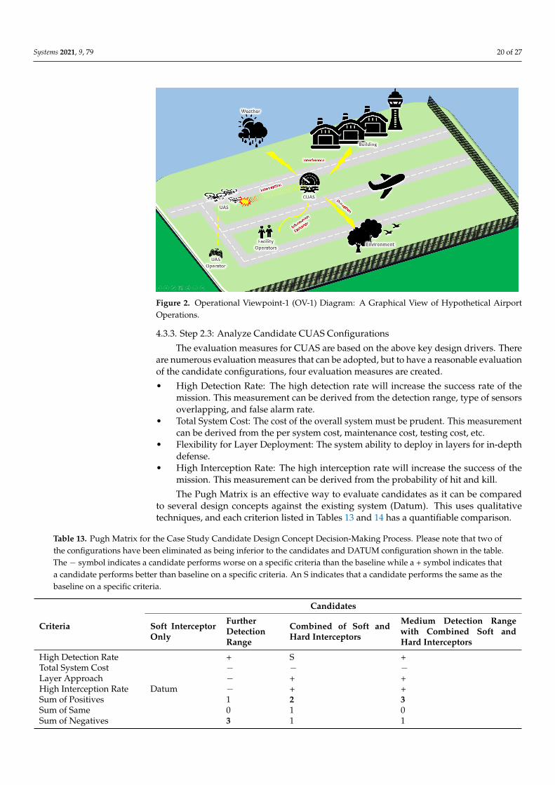
A graphical operational concept view of the hypothetical airport is shown in Figure 2.The hypothetical airport is a relatively flat area consisting of three runways and generallylow buildings except for one significantly tall control tower. Daily, there will be someground operating crews onsite to direct aircraft traffic, transport luggage and clear debrisoff the runway, and wildlife activity such as bird flocks around the trees and fence line. Thegeneral assumption of the facility condition is that there are environmental effects whichmay have intermediate levels of interference that need to be accounted for in the analysisas it may cause some degrading effects to the subsystem performance.
Systems 2021, 9, 79 20 of 27
Figure 2. Operational Viewpoint-1 (OV-1) Diagram: A Graphical View of Hypothetical AirportOperations.
4.3.3. Step 2.3: Analyze Candidate CUAS Configurations
The evaluation measures for CUAS are based on the above key design drivers. Thereare numerous evaluation measures that can be adopted, but to have a reasonable evaluationof the candidate configurations, four evaluation measures are created.
• High Detection Rate: The high detection rate will increase the success rate of themission. This measurement can be derived from the detection range, type of sensorsoverlapping, and false alarm rate.
• Total System Cost: The cost of the overall system must be prudent. This measurementcan be derived from the per system cost, maintenance cost, testing cost, etc.
• Flexibility for Layer Deployment: The system ability to deploy in layers for in-depthdefense.
• High Interception Rate: The high interception rate will increase the success of themission. This measurement can be derived from the probability of hit and kill.
The Pugh Matrix is an effective way to evaluate candidates as it can be comparedto several design concepts against the existing system (Datum). This uses qualitativetechniques, and each criterion listed in Tables 13 and 14 has a quantifiable comparison.
Table 13. Pugh Matrix for the Case Study Candidate Design Concept Decision-Making Process. Please note that two ofthe configurations have been eliminated as being inferior to the candidates and DATUM configuration shown in the table.The − symbol indicates a candidate performs worse on a specific criteria than the baseline while a + symbol indicates thata candidate performs better than baseline on a specific criteria. An S indicates that a candidate performs the same as thebaseline on a specific criteria.
Candidates
Criteria Soft InterceptorOnly
FurtherDetectionRange
Combined of Soft andHard Interceptors
Medium Detection Rangewith Combined Soft andHard Interceptors
High Detection Rate + S +Total System Cost − − −Layer Approach − + +High Interception Rate − + +Sum of Positives 1 2 3Sum of Same 0 1 0Sum of Negatives
Datum
3 1 1

Systems 2021, 9, 79 21 of 27
Table 14. Risk Associated with Severity and Likelihood of Occurrences for the Case Study.
Risk Severity Likelihood of Occurrences
Detection Blind Spot High HighMisidentification of Target High HighWrongly Activation of Interception High HighLong Process Time High MidLong Response Time High Mid
The Pugh Matrix may provide enough evidence for the designer to gather consensusfrom the stakeholders to move forward to explore the candidate configuration more deeply.
The results illustrated in Table 13 suggest that the CUAS candidate that providesmedium detection range and combination of soft and hard interceptors will be better asthe sum of positives score is the highest. With that, the designer can proceed to Section 4.4for further study of the CUAS candidate configuration.
4.4. Step 3: Evaluation and Analysis4.4.1. Step 3.1: Simulate the Proposed CUAS Configuration
Conducting simulations can reduce project cost by exploring innovative ideas orfeasibility checks prior to actual live testing on the system. The feasibility check includesthe testing of system functions and their interaction through simulations, as illustrated inFigure 3 where an example simulation output from the case study produced using CORE isshown. This exploration can streamline the number of physical tests required and generallyreduces testing costs. The baseline simulation was conducted using CORE, and the resultis shown in the supplementary material to this article.
Figure 3. Simulation of Counter-Unmanned Aerial System (CUAS) Function for the Case Study.
Systems 2021, 9, 79 22 of 27
Based on Figure 3, it is feasible to implement the chosen candidate CUAS that consistsof a medium detection range and combination of soft and hard interceptors. The nextstep is to determine the dominant factors to optimize the improvement design to meet therequirements.
4.4.2. Step 3.2: Determine Dominant Factors
The results based on the DOE show the dominant factors that have significant impactto the respective probabilities: the CUAS’s target initial range (maximum detection range)exponentially increases the probability of kill as it increases; the target speed (UAS’s maxspeed) decreases the probability of kill significantly as it increases; and any of the process,response and neutralization time that requires more than 10 s to carry out will cause anexponential decline to probability of kill. From the results presented, the key dominantfactors that have an impact on system effectiveness are the target initial range (maximumdetection range) and system response time.
4.4.3. Step 3.3: Identify Risks to the CUAS
With the dominant factors identified, the system designer then creates a list of risksaccording to their severity and the likelihood of occurrences that will affect them, asillustrated in Table 14.
4.4.4. Step 3.4: Develop Risk Mitigation
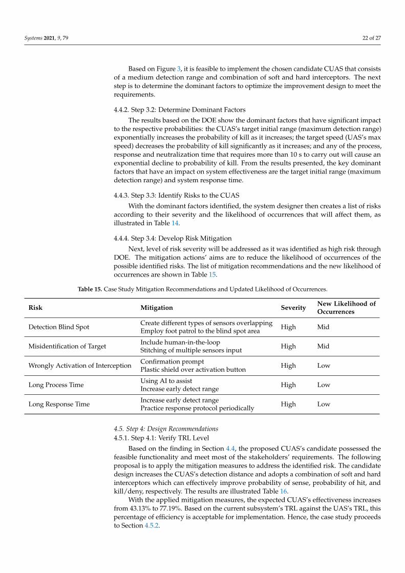
Next, level of risk severity will be addressed as it was identified as high risk throughDOE. The mitigation actions’ aims are to reduce the likelihood of occurrences of thepossible identified risks. The list of mitigation recommendations and the new likelihood ofoccurrences are shown in Table 15.
Table 15. Case Study Mitigation Recommendations and Updated Likelihood of Occurrences.
Risk Mitigation Severity New Likelihood ofOccurrences
Detection Blind Spot Create different types of sensors overlapping High MidEmploy foot patrol to the blind spot area
Misidentification of Target Include human-in-the-loop High MidStitching of multiple sensors input
Wrongly Activation of Interception Confirmation prompt High LowPlastic shield over activation button
Long Process Time Using AI to assist High LowIncrease early detect range
Long Response Time Increase early detect range High LowPractice response protocol periodically
4.5. Step 4: Design Recommendations4.5.1. Step 4.1: Verify TRL Level
Based on the finding in Section 4.4, the proposed CUAS’s candidate possessed thefeasible functionality and meet most of the stakeholders’ requirements. The followingproposal is to apply the mitigation measures to address the identified risk. The candidatedesign increases the CUAS’s detection distance and adopts a combination of soft and hardinterceptors which can effectively improve probability of sense, probability of hit, andkill/deny, respectively. The results are illustrated Table 16.
With the applied mitigation measures, the expected CUAS’s effectiveness increasesfrom 43.13% to 77.19%. Based on the current subsystem’s TRL against the UAS’s TRL, thispercentage of efficiency is acceptable for implementation. Hence, the case study proceedsto Section 4.5.2.

Systems 2021, 9, 79 23 of 27
Table 16. Expected Probability Improvement of the Proposed Candidate Design in the Case Study.
Probability of Datum Proposed Candidate Design
Sense 75% 90%Track 90% 95%Hit 80% 95%
Kill/Deny 85% 99%No-Risk 94% 96%
4.5.2. Step 4.2: Recommended CUAS Design for Implementation
To proceed with the recommendation, the stakeholders now make an informed de-cision to accept the unaddressed requirements and agree to discuss the unaddressedrequirements in the future when opportunities arise and make necessary reviews of theirTactics, Techniques, and Procedures (TTP) to ensure it will maintain system cohesivenessto support implementation efforts. This includes reassessment of project funding andreallocation of resources to support the new design configuration efforts.
Although the implementation process is underway and after the new CUAS is de-ployed, the facility commander continues to monitor emerging UAS capabilities. As newthreats emerge, the process iterates to respond in a timely manner to the new threats.
5. Discussion
With the anticipation of deploying UAS to support the facility daily operation, thereis some key insight that will be applicable in reviewing the design solution. The fastemerging UAS capabilities are known to be quick in diminishing the effectiveness of aCUAS. Through minor tweaks to the UAS, it enables a UAS to avoid CUAS’s detection andinterception. The use of proposed methodology guides the designer through a structuredSystem Engineering approach that is repetitive and consistent to compare the performanceparameters across different subsystems. The design principles are generic where it explorespeoples’ interactions with the system and leverages on the collaboration effort across thestakeholders to ensure the chosen CUAS are effective.
The use of MBSE and simulation tools will assist in verification and validation ofthe system to further explore innovative ideas and feasibility study in a cost-saving andsafe environment. Furthermore, the DOE will determine the dominant factors which thenprovides better insight to improve the system in a resource-optimized approach.
Although the data of the CUAS and the environment that was used in the case studyare intentionally fictitious, the proposed methodology provides a generic guide to thefacility commander in understanding the critical requirements of the CUAS’s deploymentthrough the proposed system engineering approach. The proposed methodology is specifi-cally useful to resolve projects with design uncertainty due to unknown parameters andprojects with limited resources.
To caveat, this methodology is proven effective in theory. However, there are stilluncertainties if there will be more complex issues to arise when actual system data setsare presented. The challenging portion of the methodology will be the development of aconsistent parameter for performance comparison. This challenge could be due to limitedtesting facilities, or the capability is at low TRL. To overcome this, the data set must begenerated through live testing of a wide variety of scenarios but there will be an increase inthe project overall budget. However, the method of acquiring realistic and usable consistentparameters is not part of the research scope. We assert that different types of facilities,different countries, and different stakeholders will find different parameters of most utilityto their specific situations. Thus, we do not recommend a specific parameter here.
The proposed methodology can address from a single UAS up to UAS with swarmcapabilities. The research did not include UAS’s capability that allows it to travel throughair and underwater which may cause a huge impact to the detection capability of CUAS, asthe UAS will be able to travel stealthily underwater and strike with agility in the air [71,72].
Systems 2021, 9, 79 24 of 27
Although the re-evaluation of design principles will be similar, the need to include under-water sensors such as sonar or proximity or new types of underwater countermeasureswill generate integration issues such as increased false alarm rate, incompatible output,and target hand-over between ground sensors and underwater sensors.
It should be noted that there are a variety of assumptions embedded in Equations (1)–(3).For instance, P(Detection) could be 0 if the detection subsystem is unable to sense or trackan incoming UAS, or is unable to transmit that information to other CUAS subsystems.This is a valid assumption based on commercially available CUAS currently on the market.
The method presented in this paper is intended to serve as an adaptable and customiz-able method for specific facility situations and for specific potential CUAS technologies.The case study assumes using fixed CUAS assets. However, the method could be modifiedto also include ground mobile, floating mobile, and air mobile assets that are both crewedand uncrewed. For instance, there are some proposals and preliminary demonstrations ofCUAS subsystems that operate from UAS platforms and from crewed ground vehicles. Apractitioner can tailor the method presented in this article to their specific facility and thespecific CUAS technologies available at the time.
The recommended expansion of this work is to include methods in generating pa-rameters that are consistent through the conduct of designing a live test to support theevaluation through validation and to conduct research of the new UASs that can travelboth in the air and underwater. The expansion of the study will support this analysis byproviding realistic results and include analysis of the new emerging technology.
6. Conclusions
In conclusion, the results of the case study demonstrate that the adoption of aniterative learning and data sharing approach such as the methodology proposed abovecan consistently ensure that the CUAS are review in time manner. The battle against fastemerging capabilities of UAS that threaten the relevancy of deployed CUAS may be a thingof the past now through enabling modular upgrades to strengthen the CUAS’s systems andtest system performance even at low TRL, which reduces the possibility of UAS exploitinginherent weakness in facility security.
Supplementary Materials: The following are available online at https://www.mdpi.com/article/10.3390/systems9040079/s1.
Author Contributions: Conceptualization, C.S.T., B.H. and D.L.V.B.; methodology, C.S.T.; software,C.S.T.; validation, C.S.T.; formal analysis, C.S.T.; investigation, C.S.T.; resources, B.H. and D.L.V.B.;data curation, C.S.T., B.H. and D.L.V.B.; writing—original draft preparation, C.S.T.; writing—reviewand editing, C.S.T., B.H. and D.L.V.B.; visualization, C.S.T.; supervision, B.H. and D.L.V.B.; projectadministration, B.H. and D.L.V.B. All authors have read and agreed to the published version of themanuscript.
Funding: This research received no external funding.
Institutional Review Board Statement: Not applicable.
Informed Consent Statement: Not applicable.
Data Availability Statement: The data presented in this study are available on request from thecorresponding author.
Conflicts of Interest: The authors declare no conflict of interest.
References1. Desjardins, J. Here’s how Commercial Drones Grew Out of the Battlefield. Business Insider, 10 August 2016.2. Lykou, G.; Moustakas, D.; Gritzalis, D. Defending Airports from UAS: A Survey on Cyber-Attacks and Counter-Drone Sensing
Technologies. Sensors 2020, 20, 3537. [CrossRef] [PubMed]3. Wallace, R.J.; Loffi, J.M. Examining Unmanned Aerial System Threats & Defenses: A Conceptual Analysis. Int. J. Aviat. Aeronaut.
Aerosp. 2015, 2, 1. [CrossRef]
Systems 2021, 9, 79 25 of 27
4. Kashyap, V. A Brief History of Drones: The Remote Controlled Unmanned Aerial Vehicles (UAVs). Available online: https://interestingengineering.com/a-brief-history-of-drones-the-remote-controlled-unmanned-aerial-vehicles-uavs (accessed on 25May 2021).
5. Stulberg, A.N. Managing the Unmanned Revolution in the U.S. Air Force. Orbis 2007, 51, 251–265. [CrossRef]6. Etzioni, A. The Great Drone Debate. Military Review, 6 October 2013.7. Forum, W.E. The Fourth Industrial Revolution: What It Means, How to Respond. Available online: https://www.weforum.org/
agenda/2016/01/the-fourth-industrial-revolution-what-it-means-and-how-to-respond/ (accessed on 26 May 2021).8. Tsekeris, C. Industry 4.0 and the digitalisation of society: Curse or cure? Homo Virtualis 2018, 1, 4–12. [CrossRef]9. Cho, K.; Cho, M.; Jeon, J. Fly a Drone Safely: Evaluation of an Embodied Egocentric Drone Controller Interface. Interact. Comput.
2016, 29, 345–354. [CrossRef]10. Arteche, D.; Chivers, K.; Howard, B.; Long, T.; Merriman, W.; Padilla, A.; Pinto, A.; Smith, S.; Thoma, V. Drone Defense System
Architecture for U.S. Navy Strategic Facilities; Naval Postgraduate School Monterey United States: Monterey, CA, USA, 2017.11. Palmer, T.S.; Geis, J.P., II. Defeating Small Civilian Unmanned Aerial Systems to Maintain Air Superiority. Air Space Power J. 2017,
31, 102–118.12. Vargas-Ramírez, N.; Paneque-Gálvez, J. The Global Emergence of Community Drones (2012–2017). Drones 2019, 3, 76. [CrossRef]13. Mckinnon, A.C. The Possible Impact of 3D Printing and Drones on Last-Mile Logistics: An Exploratory Study. Built Environ.
2016, 42, 617–629. [CrossRef]14. Giles, K.; Giammarco, K. Mission-based Architecture for Swarm Composability (MASC). Procedia Comput. Sci. 2017, 114, 57–64.
[CrossRef]15. Cummings, M.; Bruni, S.; Mercier, S.; Mitchell, P.J. Automation Architecture for Single Operator, Multiple UAV Command and
Control. Int. C2 J. 2007, 1, 1–24.16. Markus, W.; Bill, K.; Federico, A. Drone Shows: Creative Potential and Best Practices; ETH Zürich: Zürich, Switzerland, 2017; p. 18.
[CrossRef]17. Kardasz, P.; Doskocz, J.; Hejduk, M.; Wiejkut, P.; Zarzycki, H. Drones and Possibilities of Their Using. J. Civ. Environ. Eng. 2016,
6, 1–7. [CrossRef]18. Kung, C.M.; Yang, W.S.; Wei, T.Y.; Chao, S.T. The fast flight trajectory verification algorithm for Drone Dance System. In
Proceedings of the 2020 IEEE International Conference on Industry 4.0, Artificial Intelligence, and Communications Technology(IAICT), Bali, Indonesia, 7–8 July 2020; pp. 97–101. [CrossRef]
19. Vice. Drones Light Up Shanghai’s Sky with a QR Code (That You Can Scan). Vice, 17 May 2021.20. Ahn, H.; Le, D.T.; Nguyen, D.T.; Choo, H. Real-Time Drone Formation Control for Group Display. In Proceedings of the 13th
International Conference on Ubiquitous Information Management and Communication (IMCOM), Phuket, Thailand, 4–6 January2019; Volume 935, pp. 778–785. [CrossRef]
21. Dutta, A.K. Fuzzy Clustering with Particle Swarm Intelligence for Large Dataset Classification. TEM J. 2018, 7, 738–743.[CrossRef]
22. Duntz, M.E. Counter Autonomy Defense for Aerial Autonomous Systems. Ph.D. Thesis, Purdue University Graduate School,West Lafayette, IN, USA, 2020. [CrossRef]
23. Basudeb, B.; Sourav, S.; Kumar, D.A.; Neeraj, K.; Pascal, L.; Mamoun, A. Blockchain-Envisioned Secure Data Delivery andCollection Scheme for 5G-Based IoT-Enabled Internet of Drones Environment. IEEE Trans. Veh. Technol. 2020, 69, 9097–9111.[CrossRef]
24. Bera, B.; Chattaraj, D.; Das, A.K. Designing secure blockchain-based access control scheme in IoT-enabled Internet of Dronesdeployment. Comput. Commun. 2020, 153, 229–249. [CrossRef]
25. Pratim, R.P.; Kien, N. A Review on Blockchain for Medical Delivery Drones in 5G-IoT Era: Progress and Challenges. InProceedings of the 2020 IEEE/CIC International Conference on Communications in China (ICCC Workshops), Chongqing, China,9–11 August 2020; pp. 29–34. [CrossRef]
26. La Cour-Harbo, A. Mass threshold for ‘harmless’ drones. Int. J. Micro Air Veh. 2017, 9, 77–92. [CrossRef]27. Gatwick Airport: Drones Ground Flights. Available online: https://www.bbc.com/news/uk-england-sussex-46623754 (accessed
on 24 May 2021).28. Drone sightings at Changi Airport Force Closure of One Runway, Nearly 40 Flights Affected. Available online: https://
www.channelnewsasia.com/news/singapore/changi-airport-drone-sightings-one-runway-closed-11641920 (accessed on 3November 2021).
29. Aaronia. AARTOS-Drone Detection System. Available online: http://www.sarahespino.com/pdf/aaronia/Aaronia_AARTOS-Drone-Detection-System_broshure.pdf (accessed on 17 May 2021).
30. Systems, B.S. Anti-UAV Defence System. Available online: https://www.blighter.com/products/auds-anti-uav-defence-system/(accessed on 17 May 2021).
31. Raytheon Missiles & Defense. Counter-UAS. Available online: https://www.raytheonmissilesanddefense.com/capabilities/counter-uas (accessed on 17 May 2021).
32. Curtis, E. Dynamic Targeting and the Tasking Process; LeMay Center: Montgomery, AL, USA, 2019.33. Battelle. DroneDefender® Counter-UAS Device. Available online: https://www.battelle.org/government-offerings/national-
security/payloads-platforms-controls/counter-UAS-technologies/dronedefender (accessed on 18 April 2021).
Systems 2021, 9, 79 26 of 27
34. Boeing. Boeing’s Compact Laser Weapons System tracks and disables UAVs. Available online: https://www.boeing.com/features/2015/08/bds-compact-laser-08-15.page (accessed on 18 April 2021).
35. Carlini, J. The Anti-Drone Revolution: 22 Companies Building Killer Drone Tech Today from DronesX, Drone Defence. DroneDefence, 18 April 2021.
36. Williams, R. Tokyo police are using drones with nets to catch other drone. The Telegraph, 18 April 2021.37. RAPERE. Anti-Drone Interceptor. Available online: https://www.droneality.com/rapere-anti-drone-interceptor (accessed on 18
April 2021).38. Michel, A. Counter-Drone Systems; Center for the Study of the Drone at Bard College: Annandale-On-Hudson, NY, USA, 2019.39. Chauhan, B.B. Unmanned Aerial System Integration into National Airspace System and Airports: Risk Mitigation Using Content
Analysis Methodology. Ph.D. Thesis, College of Aeronautics, Metro Manila, Philippines, 2019.40. Kyrkou, C.; Timotheou, S.; Kolios, P.; Theocharides, T.; Panayiotou, C. Drones: Augmenting Our Quality of Life. IEEE Potentials
2019, 38, 30–36. [CrossRef]41. Thomas, M.; Aaron, L. Integrating unmanned aircraft systems into airport operations: From buy-in to public safety. J. Airpt.
Manag. 2019, 13, 380–390.42. Knight, J. Countering Unmanned Aircraft Systems. Master’s Thesis, Naval Postgraduate School, Monterey, CA, USA, 2019.43. Snead, J.S.; Seibler, J.M.; Inserra, D. Establishing a Legal Framework for Counter-Drone Technologies; Technical Report 12; The Heritage
Foundation: Washington, DC, USA, 2018.44. Wierzbicki, T. Investigating Drones Using Open-Source Forensic Software. Master’s Thesis, Naval Postgraduate School, Monterey,
CA, USA, 2020.45. Roder, A.; Choo, K.R.; Le-Khac, N. Unmanned Aerial Vehicle Forensic Investigation Process: Dji Phantom 3 Drone As A Case
Study. arXiv 2018, arXiv:1804.08649.46. Moon, H.; Jin, E.; Kwon, H.; Lee, S.; Gibum, K. Digital Forensic Methodology for Detection of Abnormal Flight of Drones. J. Inf.
Secur. Cybercrimes Res. 2021, 4, 27–35. [CrossRef]47. Viswanathan, S.; Baig, Z. Digital Forensics for Drones: A Study of Tools and Techniques. In Applications and Techniques in
Information Security; Batina, L., Li, G., Eds.; Springer: Singapore, 2020; pp. 29–41.48. Makori, A. Cargo plane shot down in Somalia, all occupants killed. Garlowe Online, 7 May 2020.49. Karimi, N.; Krauss, J. Under Pressure, Iran Admits It Shot Down Jetliner by Mistake. Available online: https://apnews.
com/article/europe-accidents-ap-top-news-tehran-international-news-21f4a92a2dfbc38581719664bdf6f38e (accessed on 15April 2021).
50. Cain, P. Mistaken Identity: Three Times Passenger Airliners Have Been Shot Down in Error. Available online: https://globalnews.ca/news/6389887/iran-plane-crash-three-times-passenger-planes-shot-down-error/ (accessed on 17 April 2021).
51. Jones, R.P.; Burke, A. Flight PS752 Shot Down after Being ’Misidentified’ as ’Hostile Target’, Iran’s Final Report Says; CanadianBroadcasting Corporation: Toronto, ON, Canada, 2021.
52. NIST. NIST Risk Management Framework. Available online: https://csrc.nist.gov/projects/risk-management/about-rmf(accessed on 15 April 2021).
53. Shevchenko, J. An Introduction to Model-Based Systems Engineering (MBSE). Available online: https://insights.sei.cmu.edu/blog/introduction-model-based-systems-engineering-mbse/ (accessed on 30 May 2021).
54. Tiurin, V.; Martyniuk, O.; Mirenenko, V.; Openko, P. General Approach to Counter Unmanned Aerial Vehicles. Saf. Def. 2019,5, 6–12. [CrossRef]
55. Wickens, C.D.; Lee, J.; Liu, Y.D.; Gordon-Bekcer, S. Introduction to Human Factors Engineering, 2nd ed.; Pearson: New York, NY,USA, 2004.
56. Müller, W.; Reinert, F.; Pallmer, D. Open architecture of a counter UAV system. In Open Architecture/Open Business Model Net-Centric Systems and Defense Transformation 2018; Suresh, R., Ed.; International Society for Optics and Photonics, SPIE: Bellinghamm,WA, USA, 2018; Volume 10651, pp. 34–41.
57. Kouhestani, C.; Woo, B.; Birch, G. Counter unmanned aerial system testing and evaluation methodology. In Sensors, and Command,Control, Communications, and Intelligence (C3I) Technologies for Homeland Security, Defense, and Law Enforcement Applications XVI;Carapezza, E.M., Ed.; International Society for Optics and Photonics, SPIE: Bellinghamm, WA, USA, 2017; Volume 10184, pp. 1–7.[CrossRef]
58. Cervone, H.F. Using Pugh matrix analysis in complex decision-making situations. Appl. Digit. Libr. Proj. Manag. 2009, 25, 228–232.[CrossRef]
59. Boyd, C.J.; Harris, R.E.; Kleparek, C.L.; Taylor, J.W. A Study of How Unmanned Aerial Vehicle Systems Can Improve Over-the-HorizonTargeting and Strike Missions; Naval Postgraduate School: Monterey, CA, USA, 2020.
60. Brown, G.; Carlyle, M.; Salmerón, J.; Wood, K. Defending Critical Infrastructure. Informs J. Appl. Anal. 2006, 36, 530–544.[CrossRef]
61. Brown, G.; Carlyle, M.; Salmerón, J.; Wood, K. Analyzing the Vulnerability of Critical Infrastructure to Attack and PlanningDefenses. In INFORMS TutORial in Operations Research; Informs: Denver, CO, USA, 2005; pp. 102–123. [CrossRef]
62. Marrone, S.; Nardone, R.; Tedesco, A.; D’Amore, P.; Vittorini, V.; Setola, R.; De Cillis, F.; Mazzocca, N. Vulnerability modeling andanalysis for critical infrastructure protection applications. Int. J. Crit. Infrastruct. Prot. 2013, 6, 217–227. [CrossRef]

Systems 2021, 9, 79 27 of 27
63. Makhloof, M.A.A.; Waheed, M.E.; Badawi, U.A.E.R. Real-time aircraft turnaround operations manager. Prod. Plan. Control 2014,25, 2–25. [CrossRef]
64. Changi Airport Group. Available online: https://www.changiairport.com/corporate/our-expertise/air-hub/traffic-statistics.html (accessed on 16 July 2021).
65. Spark, W. Average Weather in Singapore. Available online: https://weatherspark.com/y/114655/Average-Weather-in-Singapore-Year-Round (accessed on 18 July 2021).
66. Williams, A.P.; Scharre, P.D. Defining Autonomy in Systems: Challenges and Solutions. In Autonomous Systems: Issues for DefencePolicymakers; NATO Allied Command Transformation: Norfolk, VA, USA, 2008; pp. 41–42.
67. Martin-Emerson, R.; Wickens, C.D. Superimposition, Symbology, Visual Attention, and the Head-Up Display. Hum. Factors 1997,39, 581–601. [CrossRef]
68. Erjavac, A.J.; Iammartinos, R.; Fossaceca, J. An Evaluation of Human Factors Failure Data in Relation to System ReadinessAssessment. In Proceedings of the World Congress on Engineering and Computer Science 2016 Vol II, San Francisco, CA, USA,19–21 October 2016.
69. Institute, D.T.; The Association for Unmanned Vehicle Systems International (AUVSI). Global Trends of Unmanned Aerial Systems;Technical Report; Danish Technological Institute [DTI]: Taastrup, Denmark, 2019.
70. DJI. DJI Drone Comparison. Available online: https://www.dji.com/products/comparison-consumer-drones?from=store-product-page (accessed on 30 May 2021).
71. How China’s Flying Submarine Drone Could Change the Way Sea Battles Are Fought. Available online: https://www.scmp.com/news/china/science/article/3141856/how-chinas-flying-submarine-drone-could-change-way-sea-battles (accessed on 30July 2021).
72. SwellPro. SplashDrone3+. Available online: https://www.swellpro.com/waterproof-splash-drone.html (accessed on 1August 2021).
Copyright © 2022 FDOKUMEN