mullite glass ceramics production from coal ash and alumina ...
Upload
independentCategory
view
0download
0
http://journa
dof
h
ial
1706
HelpCommentsWelcomeJournal of
MATERIALS RESEARCH
Synthesis, morphology, and formation mechanism of mulliteparticles produced by ultrasonic spray pyrolysisDj. JanackovicFaculty of Technology and Metallurgy, Belgrade, Yugoslavia
V. JokanovicInstitute for Technology of Nuclear and Other Mineral Row Materials, Belgrade, Yugoslavia
Lj. Kostic-Gvozdenovi´cFaculty of Technology and Metallurgy, Belgrade, Yugoslavia
Lj. ZivkovicFaculty of Electronics, Niˇs, Yugoslavia
D. UskokovicInstitute of Technical Sciences of the Serbian Academy of Sciences and Arts, Belgrade, Yugoslavia
(Received 7 August 1995; accepted 12 February 1996)
Submicrometer spherical particles of mullite powder were synthesized by ultrasonicspray pyrolysis of emulsion and solutions, using tetra-ethyl-orthosilicate (TEOS) orsilicic-acid and Al(NO3)3 ? 9H2O as initial compounds. Crystallization of mullite phasewas determined by differential thermal (DT), thermogravimetric (TG), infrared (IR), anx-ray analyses. The synthesis of mullite from TEOS emulsion occurs by crystallizationg –Al2O3 (or Al, Si-spinel) from the amorphous phase and its subsequent reaction witamorphous SiO2, as well as by crystallization of pseudotetragonal mullite below 1000±Cand its subsequent phase transformation into orthorhombic mullite. In the powdersproduced from silicic acid solutions, synthesis of mullite occurs only by crystallizationof g –Al2O3 between 900 and 1000±C and its further reaction with amorphous SiO2
between 1100 and 1200±C. Particle formation mechanism depended directly on the initemulsion or solution preparation, i.e., on the phase separation in the emulsion and onthe silicic-acid crosslinking conditions.
e
dnv
rat
,n-e
the-sgedal
Bythere,ins
ced
st.r
I. INTRODUCTION
Because of its relatively high bending strengthlow and high temperatures (200–500 MPa), resistanccreeping, relatively high melting point (around 1850±C),and resistance to thermal shock, mullite has bewidely used in the refractory materials industry.1,2
Having a relatively low dielectric constant (e 6–6.7), low thermal expansion coefficient (4–531026 ±C21 in the 25–800±C temperature range), anlow sintering temperature which enables its cosinteriwith metals, mullite and mullite glass-ceramics habeen used for manufacturing substrates for integracircuits and microchips.1,3 Optical properties of mulliteglass-ceramics make it applicable to production ofwindow-glass material for infrared light in a wavelengtrange of 3–5mm, and, with Cr31 addition, as an opticalactivator in lasers.1
Ultrasonic spray pyrolysis is a useful method fosynthesis of powders of submicrometer spherical pacles of narrow size distribution with defined chemicand phase compositions. The method integrates ulsonic formation of aerosol droplets and their dire
ls.cambridge.org Downloaded: 15 May 2013
J. Mater. Res., Vol. 11, No. 7, Jul 1996
atto
en
ge
ted
ah
rti-lra-ct
introduction into a reactor. In the course of pyrolysisthe droplets undergo solvent evaporation, precipitatioof dissolved substance, drying, thermolysis of precipitated particles, and, eventually, sintering into densparticles. Due to very rapid rates of these processes,formed particles retain their initial chemical homogeneity achieved in the starting solution (if the precursorare not volatile), sol, or suspension. Another advantais that each droplet, i.e., formed particle, is subjecteto the same reaction conditions, so that the chemicand phase composition of all particles are the same.controlling the specific process parameters, such astemperature, type, and pressure of reaction atmosphetemperature gradient and residence time of particlesthe reactor, as well as the choice of initial compoundand the starting solution preparations, a direct influenon the morphology, size distribution, homogeneity, anthe phase composition of particles is provided.4–12
Kanzaki and Tabata13 synthesized mullite powdersby spray pyrolysis using TEOS and aluminum-nitrate ainitial compounds dissolved in a water-methanol solvenThe pyrolysis was carried out by a twin-fluid atomize
IP address: 147.91.1.45
1996 Materials Research Society

Dj. Janackovic et al.: Synthesis, morphology, and formation mechanism of mullite particles
r
n
r
o
-
aeRc
i
tan
l
h
e
S
teb-ter
of
e
f
-nt
ir
swg
ord
ds,for
na
ly,r,s
byon.L-dedl
n-n
-
nd0,
dh
in a furnace at a temperature from 350 to 650±C.X-ray analysis revealed amorphous powders. Subsequcalcination of the samples at 970±C resulted in a directcrystallization of mullite from the amorphous phase. Thparticles were of hollow structure; i.e., they were formeby surface precipitation of the starting compounds.
Moore et al.14 synthesized ultrafine mullite powdeby the same method using SiO2 obtained from thevapor phase, as an initial compound. The solution watomized into a two-zone furnace having a differetemperature in each zone. As confirmed, the powdconsisted of nonagglomerated and nonhollow sphe(0.1–2mm in diameter). The crystallization ofg –Al2O3
took place at an elevated temperature of the second z(1200±C), while at higher temperatures (1400±C) onlythe mullite phase was observed.
Ocanaet al.15 reported the synthesis of mullite powder from hydrolyzed TMOS (tetra-methyl-orthosilicateand aluminum-sec-butoxide aerosol. The aerosol wnebulized and introduced into a heating column150 ±C, and then the resultant powder was calcinat higher temperatures. As shown by the x-ray, Iand NMR analyses, the mullite synthesis took plaby a simultaneous crystallization ofg –Al2O3 (orAl, Si-spinel) and pseudotetragonal mullite16,17 from theamorphous phase at a 800–1000±C temperature range.
Sakuraiet al.18 performed the synthesis of mullitepowder by ultrasonic spray pyrolysis using TEOS analuminum-isopropoxide hydrolyzed by water addedthe ratio H2O : TEOS. 4. Direct mullite synthesis fromthe amorphous phase occurred at 1000±C, which was aconsequence of the formation of an Si[OAl(OR)2)3OHcomplex in the initial solution.
The aim of this paper was to synthesize the mullipowder of submicrometer spherical particles by ultrsonic spray pyrolysis of emulsion and solutions, startifrom the organic (TEOS) and inorganic (silicic acidsilicon compounds, and to determine the influencethe compounds on the formation mechanism of particand on the phase transformations during heating.
II. EXPERIMENTAL PROCEDURE
TEOS [Si(OC2H5)4, Silester XAR Monsato-Europe-Belgium], silicic acid [Si(OH)4), and Al(NO3)3 ? 9H2O(Merck, PA) were used as starting compounds for tsynthesis of stoichiometric (3 : 2) mullite. Silicic acidwas prepared by passing Na-silicate through a glacolumn filled with a cation exchanger in an H1-form. Tohinder dissociation of silanol groups and to prevent thcondensation, a diluted 3% aqueous solution of silicacid (calculated as SiO2) with a pH value of 2.8 (pointof zero charge) was used.
Three starting 0.025 M solutions were prepared:
http://journals.cambridge.org Downloaded: 15 May 2013
J. Mater. Res., Vol. 1
ent
ed
asteres
ne
)astd,e
dn
e-g
)ofes
e
ss
iric
M-1 sample: in an aqueous emulsion of TEO(TEOS : water 1 : 17, t 80 ±C) with the additionof HCl as a catalyst for TEOS hydrolysis (pH 1),the aqueous solution of Al(NO3)3 ? 9H2O was added.In the prepared emulsion, the naphthalene sulfona(AEROSOL-NS-Surfactant) as a surface-active sustance was also added to form a stable TEOS waemulsion.
M-2 sample: Al(NO3)3 ? 9H2O was dissolved in theaqueous solution of silicic acid (t 20 ±C, pH 2.5);
M-3 sample: TEOS previously dissolved inethanol was added in the aqueous solutionAl(NO3)3 ? 9H2O (t 80 ±C, pH 1) with HNO3
addition (as a catalyst for TEOS hydrolysis), in thratio TEOS : ethanol : water 1 : 2 : 17 (such a highTEOS : water ratio had to be used due to difficulty oatomizing alcohol solutions). In this way, the TEOSwas completely hydrolyzed, forming silicic acid.
The solution atomization was carried with an ultrasonic GAPUSOL-RBI-9001 atomizer at a resonafrequency of 2.5 MHz and a capacity of 400 mlyh,generating aerosol droplets of a mean diameter of 2mm.
Aerosol droplets were then inserted into an astream at a flow rate of 30–40 lyh, in a 1 m long fur-nace, at 900±C. The residence time of droplets/particleinside the furnace was 95 s, assuming the air florate and droplet velocities to be equal. The heatinrate of droplets/particles was 18±Cys. The precipitatedpowder from a glass tube at the outlet of the reactand from a washing bottle, also containing absorbegases released by degradation of the initial compounwas collected. A schematic diagram of the apparatuspowder synthesis was given earlier.8,11,12
Morphology and particle sizes were analyzed ia JEOL-JSM-5300 scanning electron microscope atcathode voltage from 25 to 30 kV and, subsequentfrom micrographs taken by a semiautomatic analyzeVideo Plan, Kontron. Preparation of the powders wamade by their eventual deagglomeration in ethanolan ultrasonic bath, and subsequent evaporation in carbTransmission electron microscopy was done by a JEOJEM-100cx instrument. Sample preparation was maby sealing the powder with an epoxy resin (araldite) anby mechanical sample thinning. A qualitative chemicaanalysis was made by an EDS equipment, Oxford Istruments QX-2000s, in a 0.5–20 keV x-ray radiatiorange. DT and TG analyses were made using a MOMDerivatograf C, at a temperature up to 1300±C anda heating rate of 15±Cymin, in air. Determination ofthe powder phase composition after spray pyrolysis asubsequent calcination of the powders at 900, 1001100, 1200, and 1300±C were performed by a PhilipsPW-1710 diffractometer (the M-1 and M-2 samples) anby a Siemens D500 diffractometer (the M-3 sample) witCu Ka radiation in the range of angles 2u 5–65± and
IP address: 147.91.1.45
1, No. 7, Jul 1996 1707
Dj. Janackovic et al.: Synthesis, morphology, and formation mechanism of mullite particles
n
i
l
ts.Sce-restes
hwas
heles
-
es
mingts.edto
tionghis
of
errag-
ofseses,cictedbeatts
5–75±, respectively. IR analysis was carried out byPerkin-Elmer 782 spectrometer in a wave number ranfrom 400 to 1600 cm21. Samples were prepared by thKBr method, in the sample to KBr ratio equal to 1 : 100
III. RESULTS AND DISCUSSION
A. Morphology and formation mechanismof particles
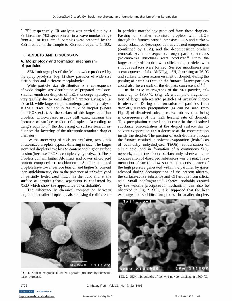
SEM micrographs of the M-1 powder produced bthe spray pyrolysis (Fig. 1) show particles of wide sizdistribution and different morphologies.
Wide particle size distribution is a consequencof wide droplet size distribution of prepared emulsioSmaller emulsion droplets of TEOS undergo hydrolysvery quickly due to small droplet diameter giving a silcic acid, while larger droplets undergo partial hydrolysat the surface, but not in the bulk of droplet (wherthe TEOS exist). At the surface of this larger emulsiodroplets, C2H5-organic groups still exist, causing thedecrease of surface tension of droplets. AccordingLang’s equation,19 the decreasing of surface tension influences the lowering of the ultrasonic atomized dropdiameter.
By the atomizing of such an emulsion, two kindof atomized droplets appear, differing in size. The largatomized droplets have low Si content and higher surfatension (because TEOS is completely hydrolyzed). Thedroplets contain higher Al-nitrate and lower silicic acicontent compared to stoichiometric. Smaller atomizdroplets have lower surface tension and higher Si contthan stoichiometric, due to the presence of unhydrolyzor partially hydrolyzed TEOS in the bulk and at thsurface of droplet (phase separation is confirmedXRD which show the appearance of cristobalite).
The difference in chemical composition betweelarger and smaller droplets is also causing the differen
FIG. 1. SEM micrographs of the M-1 powder produced by ultrasonspray pyrolysis.
http://journals.cambridge.org Downloaded: 15 May 2013
1708 J. Mater. Res., Vol.
agee.
ye
e.
is-isen
to-et
sercese
dedentedeby
nce
ic
in particles morphology produced from these droplePassing of smaller atomized droplets with TEOthrough the furnace caused intensive TEOS and surfaactive substance decomposition at elevated temperatu(confirmed by DTA), and the decomposition producremoval. As a consequence, rough particle surfac(volcano-like structure) were produced.6 From thelarger atomized droplets with silicic acid, particles witsmooth surfaces were formed. Surface smoothnessa consequence of the Al(NO3)3 ? 6H2O melting at 76±Cand surface tension action on melt of droplet, during tpassing of particles through the furnace. Larger particcould also be a result of the droplets coalescence.10,12
In the SEM micrographs of the M-1 powder, calcined up to 1300±C (Fig. 2), a complete fragmenta-tion of larger spheres into particles of irregular shapis observed. During the formation of particles fromdroplets, surface precipitation (as can be seen froFig. 2) of dissolved substances was observed as bea consequence of the high heating rate of dropleThis precipitation caused an increase in the dissolvsubstance concentration at the droplet surface duesolvent evaporation and a decrease of the concentrainside the droplet. The passing of such droplets throuthe furnace resulted in solvent evaporation (hydrolysof eventually unhydrolyzed TEOS), condensationsilicic acid, and in formation of a continuous SiO2
network, but at the droplet surface only where a highconcentration of dissolved substances was present. Fmentation of such hollow spheres is a consequencethe high pressure generated within the particles by gareleased during decomposition of the present nitratthe surface-active substance and OH groups from siliacid. Small nonfragmented spheres, probably creaby the volume precipitation mechanism, can alsoobserved in Fig. 2. Still, it is supposed that the heexchange and solidification process in smaller drople
FIG. 2. SEM micrographs of the M-1 powder calcined at 1300±C.
IP address: 147.91.1.45
11, No. 7, Jul 1996

Dj. Janackovic et al.: Synthesis, morphology, and formation mechanism of mullite particles
n
to
in
o
no
ede
d
b-d
e-of
s,e
ofm
re
ic
(below 300 nm in size) proceeds so fast, preventichanges in precursor concentration in bulk of droplewhich leads to the formation of nonhollow spheres.
Highly spheroidal nonagglomerated particles, mossubmicrometer in size, were observed in SEM micrgraphs of the M-2 powder (Fig. 3) produced by thpyrolysis. The particle surfaces are smooth as a resof the Al-nitrate melting at 76±C, action of the surfacetension on melt of droplet, and of the homogeneous dtribution of silicic acid in solution and its condensatiodue to solvent evaporation during pyrolysis.
SEM micrographs of the M-2 powder calcined a1300 ±C, given in Fig. 4, show also the presencesubmicrometer spherical particles of smooth surfaces aof a relatively narrow size distribution. No fragmentatioof particles is observed, suggesting the formationnonhollow spherical particles.
FIG. 3. SEM micrographs of the M-2 powder produced by ultrasonspray pyrolysis.
FIG. 4. SEM micrographs of the M-2 powder calcined at 1300±C.
http://journals.cambridge.org Downloaded: 15 May 2013
J. Mater. Res., Vol. 1
gt,
ly-
eult
s-
tfnd
f
ic
Spherical nonhollow and smooth nonagglomeratparticles of narrow size distribution can be seen in thSEM micrographs of the M-3 powder (Fig. 5) obtaineby spray pyrolysis.
Spherical particles and no fragmentation are oserved in SEM micrographs of the M-3 powder calcineat 1200±C, (Fig. 6). Particles have rough surfaces rsulting from an intensive evaporation and combustionthe present ethanol.6
The volume precipitation of dissolved substancewithin the droplets occurs during the particle formationas can be concluded from the TEM micrographs of thM-3 powder calcined at 1200±C, shown in Fig. 7. Theobserved particle structure consists of a great numbernanocrystals of a rod (cylinder) shape, around 100 nin length and 20 nm in diameter. Nanocrystals ainterwoven into the whole particle volume, forming
FIG. 5. SEM micrographs of the M-3 powder produced by ultrasonspray pyrolysis.
FIG. 6. SEM micrographs of the M-3 powder calcined at 1200±C.
IP address: 147.91.1.45
1, No. 7, Jul 1996 1709
Dj. Janackovic et al.: Synthesis, morphology, and formation mechanism of mullite particles
hne
rthifie
nit
e
soo
g
s
re
e
ero
on
a-3
h,
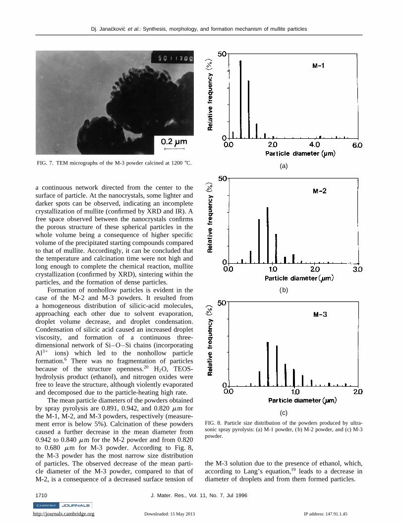
FIG. 7. TEM micrographs of the M-3 powder calcined at 1200±C.
a continuous network directed from the center to tsurface of particle. At the nanocrystals, some lighter adarker spots can be observed, indicating an incomplcrystallization of mullite (confirmed by XRD and IR). Afree space observed between the nanocrystals confithe porous structure of these spherical particles inwhole volume being a consequence of higher specvolume of the precipitated starting compounds comparto that of mullite. Accordingly, it can be concluded thathe temperature and calcination time were not high along enough to complete the chemical reaction, mullcrystallization (confirmed by XRD), sintering within theparticles, and the formation of dense particles.
Formation of nonhollow particles is evident in thcase of the M-2 and M-3 powders. It resulted froma homogeneous distribution of silicic-acid moleculeapproaching each other due to solvent evaporatidroplet volume decrease, and droplet condensatiCondensation of silicic acid caused an increased dropviscosity, and formation of a continuous threedimensional network of Si–O–Si chains (incorporatinAl 31 ions) which led to the nonhollow particleformation.6 There was no fragmentation of particlebecause of the structure openness.20 H2O, TEOS-hydrolysis product (ethanol), and nitrogen oxides wefree to leave the structure, although violently evaporatand decomposed due to the particle-heating high rate
The mean particle diameters of the powders obtainby spray pyrolysis are 0.891, 0.942, and 0.820mm forthe M-1, M-2, and M-3 powders, respectively (measurment error is below 5%). Calcination of these powdecaused a further decrease in the mean diameter fr0.942 to 0.840mm for the M-2 powder and from 0.820to 0.680 mm for M-3 powder. According to Fig. 8,the M-3 powder has the most narrow size distributioof particles. The observed decrease of the mean pacle diameter of the M-3 powder, compared to thatM-2, is a consequence of a decreased surface tensio
http://journals.cambridge.org Downloaded: 15 May 2013
1710 J. Mater. Res., Vol. 1
edte
msecd
tde
,n,n.let-
ed
.d
-sm
nrti-fof
(a)
(b)
(c)
FIG. 8. Particle size distribution of the powders produced by ultrsonic spray pyrolysis: (a) M-1 powder, (b) M-2 powder, and (c) M-powder.
the M-3 solution due to the presence of ethanol, whicaccording to Lang’s equation,19 leads to a decrease indiameter of droplets and from them formed particles.
IP address: 147.91.1.45
1, No. 7, Jul 1996

Dj. Janackovic et al.: Synthesis, morphology, and formation mechanism of mullite particles
ne0
f
w
dl.
B. Phase analyses
1. DT and TG analyses
The DT and TG data for the M-1 powder (heateto 1300±C, the heating rate 15±Cymin) illustrated, inFig. 9(a), show an exothermic peak (10) at around 400±Ccreated by the combustion of surface active substaand unhydrolyzed TEOS organic groups. An extendexothermic peak (20), in a temperature range from 80
http://journals.cambridge.org Downloaded: 15 May 2013
J. Mater. Res., Vol. 1
d
ced
to 1000±C, can be ascribed to the crystallization og –Al2O3
21,22 or Al, Si-spinel phase2l–23 or pseudotetrag-onal mullite,17,21,23,24,25 and to the combustion of theresidual organic groups. The TG curve shows a sloweight loss to 800±C where a rapid loss occurs as aresult of the remaining organic group combustion, anthe remaining OH groups and nitrogen gases remova
DT and TG data of the M-2 powder (heated to1300 ±C, at a heating rate of 15±Cymin) given in
(a) (b)
(c)
FIG. 9. DT and TG data for the powders, at a 15±Cymin heating rate: (a) M-1 powder, (b) M-2 powder, and (c) M-3 powder.
IP address: 147.91.1.45
1, No. 7, Jul 1996 1711

Dj. Janackovic et al.: Synthesis, morphology, and formation mechanism of mullite particles
a) M-1
(a) (b)
FIG. 10. Diffractograms of powders produced by ultrasonic spray pyrolysis and subsequently calcined at different temperatures: (powder, (b) M-2 powder, and (c) M-3 powder.
)
t
-lwre
n
c
e
-
-
genis
of
Fig. 9(b) show an endothermic peak (100) at 500±C, in-dicating also a beginning of the weight loss (TG curveIt is connected to the removal of OH groups, i.e., H2O,after condensation of uncondensed OH groups presenthe SiO2 network structure. An exothermic peak (200) at900 ±C on the DT curve is attributed to the crystallization of g –Al2O3, Al, Si-spinel, or of pseudotetragonamullite. At the same temperature, the TG curve shofurther weight loss ascribed to the release of themaining OH groups and trapped nitrogen gases mapossible by the crystallization (the crystallization opethe structure enabling nitrogen gas molecules, trappin the SiO2 network structure, to escape). Appearan
http://journals.cambridge.org Downloaded: 15 May 2013
1712 J. Mater. Res., Vol. 1
.
in
s-
desede
of an extended exothermic peak (300), as a result oforthorhombic mullite crystallization, is observed on thDT curve at 1150±C.
Figure 9(c) shows DT and TG data for the M-3 powder, heated to 1100±C at a heating rate of 15±Cymin.There is an exothermic peak (1000) at 966±C attributedto the crystallization of pseudotetragonal mullite, Al, Sispinel phase, or ofg –Al2O3. The TG curve shows a con-tinuous but slow weight loss of particles during heatindue to the release of OH groups and remaining nitroggases. No exothermic peak at lower temperaturesobtained, which means that the hydrolysis processTEOS was completed.
IP address: 147.91.1.45
1, No. 7, Jul 1996

Dj. Janackovic et al.: Synthesis, morphology, and formation mechanism of mullite particles
or
m
)
o
n
-t
tn
esse
-y
r-
tndn
lsois.
sebut
le
nk
n
-
e,
d
nd
r-ee
(c)
FIG. 10. (continued from previous page)
2. X-ray analysis
Figure 10(a) shows diffractograms of the M-1 powder obtained by spray pyrolysis, and calcined at 901000, 1100, 1200, and 1300±C for 2 h. For the sampleobtained by spray pyrolysis, the presence of an amphous phase is observed, suggesting a short particleidence time and the low furnace temperature insufficiefor crystallization of mullite or transient Al2O3 phases,which is in agreement with the EDS data. Diffractograof the powder calcined at 1000±C shows diffractionpeaks corresponding to mullite (ASTM card 15-776Appearance ofg –Al2O3 (ASTM card 10-425) (or Al, Si-spinel phase) is observed. At the diffraction peak, fthe sample calcined at 1100±C, at 2u 26.380± (d 0.337 nm) corresponding to the 120,210 reflectionsmullite, no splitting is registered which confirms tetragonal symmetry of the mullite obtained.16,17 Diffractionpeaks at 2u 45.185± and 46.030± (d 0.2115 nmand d 0.2005 nm), corresponding to the diffractiopeaks of g –Al2O3 (or Al, Si-spinel phase), are moreintensive than those for the sample calcined at 1000±C.Appearance of theg –Al2O3 phase is a result of the inhomogeneity of the starting solution and sprayed dropleDiffraction peaks for mullite, calcined at 1200±C, aremore intensive, but the diffraction peaks for cristobali(ASTM card 11-695) which also appear are the cosequence of insufficient homogeneity of the startinsolution/emulsion. Diffraction peaks forg –Al2O3 (or
http://journals.cambridge.org Downloaded: 15 May 2013
J. Mater. Res., Vol. 1
-0,
r-es-nt
.
r
of-
s.
e-g
Al, Si-spinel phase) are not observed, which indicatthat mullite was produced from the reaction of this phawith amorphous SiO2.
Figure 10(b) shows diffractograms of the M-2 powder. The powder obtained by spray pyrolysis is x-raamorphous. For the sample calcined at 900 and 1000±C,diffraction peaks are observed at 2u 37.520± and45.995± corresponding tog –Al2O3. Further heating at1200 ±C, gives diffraction peaks of mullite, but theabsence of diffraction lines of the transientg –Al2O3
phase (Al, Si-spinel phase) proves its reaction with amophous SiO2 giving mullite.24,26 A higher degree of mul-lite crystallinity is observed for the sample calcined a1300 ±C, but it is supposed (based on the background adiffraction peak intensities) that the mullite productioprocess was not completed.
In Fig. 10(c), showing diffractograms of the M-3powder, the presence of the amorphous phase is aobserved for the sample obtained by the spray pyrolysIn the diffractogram of the sample calcined at 1000±C,beginning of theg –Al2O3 crystallization, i.e., appear-ance of extended less distinctive peaks at 2u 45.99±
and 67±, is observed. Appearance of the spinel phashows that the starting solution was inhomogeneous,a separation of phases into a rich Al2O3 and a richSiO2 phase took place. Further calcination of the sampat 1100 and 1200±C had as a result more intensivecrystallization ofg –Al2O3 and the appearance of a newdiffraction peak at 2u 37.52± also corresponding tothis phase which reacted with amorphous SiO2 giv-ing mullite.21,24,26 For the sample calcined at 1200±C,g –Al2O3 is still observed, which means that the reactioof mullite formation was not completed. Diffraction peaat 2u 29.633± corresponds to the sample carrier.
3. IR analysis
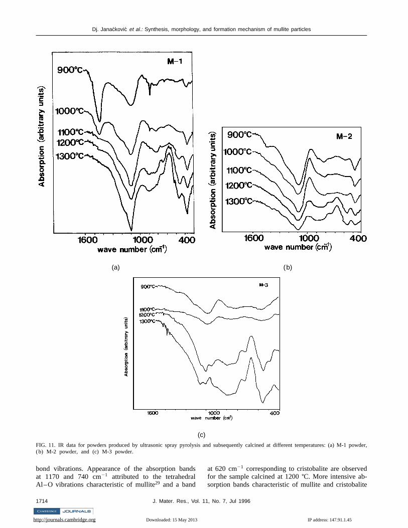
IR analysis data for the M-1 powder are shown iFig. 11(a). A broad absorption band at 1050–1100 cm21
and a band at 470 cm21 ascribed to the Si–O vibrationsof amorphous SiO221 are observed for the sample calcined at 900±C. A shift in the first peak from 1100to 1050 cm21 suggests formation, in a certain degreof Si–O–Al bonds.21,27 Bands at 890 and 720 cm21
are attributed to the tetrahedral Al–O bond vibrations,28
while the broader band at 800–840 cm21 correspondsprobably to the octahedral and tetrahedral Al–O bonvibrations. For the sample calcined at 1000±C, a de-crease in intensity of the absorption bands at 890 a720 cm21 and appearance of a broad band at 560 cm21
corresponding to the octahedral Al–O vibrations chaacteristic of mullite29 are registered. For the samplcalcined at 1100±C, the bands become more intensivat 1100, 560, and 470 cm21 and the band appearingat 810 cm21 can correspond to the octahedral Al–O
IP address: 147.91.1.45
1, No. 7, Jul 1996 1713
Dj. Janackovic et al.: Synthesis, morphology, and formation mechanism of mullite particles
powder,
(a) (b)
(c)
FIG. 11. IR data for powders produced by ultrasonic spray pyrolysis and subsequently calcined at different temperatures: (a) M-1(b) M-2 powder, and (c) M-3 powder.
ld
e
bond vibrations. Appearance of the absorption banat 1170 and 740 cm21 attributed to the tetrahedraAl–O vibrations characteristic of mullite29 and a band
http://journals.cambridge.org Downloaded: 15 May 2013
1714 J. Mater. Res., Vol.
dsat 620 cm21 corresponding to cristobalite are observefor the sample calcined at 1200±C. More intensive ab-sorption bands characteristic of mullite and cristobalit
IP address: 147.91.1.45
11, No. 7, Jul 1996
Dj. Janackovic et al.: Synthesis, morphology, and formation mechanism of mullite particles
a
ep
t
l
in
,
a
va
a
)
p
O
n
e
:r
Sceoes-ss
letae3olce
etedginto
l-
ess
nce
e
nd
c.
),
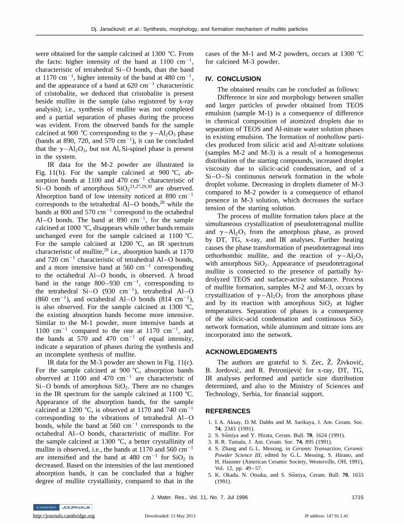
were obtained for the sample calcined at 1300±C. Fromthe facts: higher intensity of the band at 1100 cm21,characteristic of tetrahedral Si–O bonds, than the baat 1170 cm21, higher intensity of the band at 480 cm21,and the appearance of a band at 620 cm21 characteristicof cristobalite, we deduced that cristobalite is presebeside mullite in the sample (also registered by x-ranalysis); i.e., synthesis of mullite was not completeand a partial separation of phases during the procwas evident. From the observed bands for the samcalcined at 900±C corresponding to theg –Al2O3 phase(bands at 890, 720, and 570 cm21), it can be concludedthat theg –Al2O3, but not Al, Si-spinel phase is presenin the system.
IR data for the M-2 powder are illustrated inFig. 11(b). For the sample calcined at 900±C, ab-sorption bands at 1100 and 470 cm21 characteristic ofSi–O bonds of amorphous SiO2
21,27,29,30 are observed.Absorption band of low intensity noticed at 890 cm21
corresponds to the tetrahedral Al–O bonds,28 while thebands at 800 and 570 cm21 correspond to the octahedraAl–O bonds. The band at 890 cm21, for the samplecalcined at 1000±C, disappears while other bands remaunchanged even for the sample calcined at 1100±C.For the sample calcined at 1200±C, an IR spectrumcharacteristic of mullite,29 i.e., absorption bands at 1170and 720 cm21 characteristic of tetrahedral Al–O bondsand a more intensive band at 560 cm21 correspondingto the octahedral Al–O bonds, is observed. A broband in the range 800–930 cm21, corresponding tothe tetrahedral Si–O (930 cm21), tetrahedral Al–O(860 cm21), and octahedral Al–O bonds (814 cm21),is also observed. For the sample calcined at 1300±C,the existing absorption bands become more intensiSimilar to the M-1 powder, more intensive bands1100 cm21 compared to the one at 1170 cm21, andthe bands at 570 and 470 cm21 of equal intensity,indicate a separation of phases during the synthesisan incomplete synthesis of mullite.
IR data for the M-3 powder are shown in Fig. 11(cFor the sample calcined at 900±C, absorption bandsobserved at 1100 and 470 cm21 are characteristic ofSi–O bonds of amorphous SiO2. There are no changesin the IR spectrum for the sample calcined at 1100±C.Appearance of the absorption bands, for the samcalcined at 1200±C, is observed at 1170 and 740 cm21
corresponding to the vibrations of tetrahedral Al–bonds, while the band at 560 cm21 corresponds to theoctahedral Al–O bonds, characteristic of mullite. Fothe sample calcined at 1300±C, a better crystallinity ofmullite is observed, i.e., the bands at 1170 and 560 cm21
are intensified and the band at 480 cm21 for SiO2 isdecreased. Based on the intensities of the last mentioabsorption bands, it can be concluded that a highdegree of mullite crystallinity, compared to that in th
http://journals.cambridge.org Downloaded: 15 May 2013
J. Mater. Res., Vol. 1
nd
ntydssle
d
e.t
nd
.
le
r
eder
cases of the M-1 and M-2 powders, occurs at 1300±Cfor calcined M-3 powder.
IV. CONCLUSION
The obtained results can be concluded as followsDifference in size and morphology between smalle
and larger particles of powder obtained from TEOemulsion (sample M-1) is a consequence of differenin chemical composition of atomized droplets due tseparation of TEOS and Al-nitrate water solution phasin existing emulsion. The formation of nonhollow particles produced from silicic acid and Al-nitrate solution(samples M-2 and M-3) is a result of a homogeneoudistribution of the starting compounds, increased dropviscosity due to silicic-acid condensation, and ofSi–O–Si continuous network formation in the wholdroplet volume. Decreasing in droplets diameter of M-compared to M-2 powder is a consequence of ethanpresence in M-3 solution, which decreases the surfatension of the starting solution.
The process of mullite formation takes place at thsimultaneous crystallization of pseudotetragonal mulliand g –Al2O3 from the amorphous phase, as proveby DT, TG, x-ray, and IR analyses. Further heatincauses the phase transformation of pseudotetragonalorthorhombic mullite, and the reaction ofg –Al2O3
with amorphous SiO2. Appearance of pseudotetragonamullite is connected to the presence of partially hydrolyzed TEOS and surface-active substance. Procof mullite formation, samples M-2 and M-3, occurs bycrystallization ofg –Al2O3 from the amorphous phaseand by its reaction with amorphous SiO2 at highertemperatures. Separation of phases is a consequeof the silicic-acid condensation and continuous SiO2
network formation, while aluminum and nitrate ions arincorporated into the network.
ACKNOWLEDGMENTS
The authors are grateful to S. Zec,Z. Zivkovic,B. Jordovic, and R. Petronijevi´c for x-ray, DT, TG,IR analyses performed and particle size distributiodetermined, and also to the Ministry of Sciences anTechnology, Serbia, for financial support.
REFERENCES
1. I. A. Aksay, D. M. Dabbs and M. Sarikaya, J. Am. Ceram. So74, 2343 (1991).
2. S. Somiya and Y. Hirata, Ceram. Bull.70, 1624 (1991).3. R. R. Tumala, J. Am. Ceram. Soc.74, 895 (1991).4. S. Zhang and G. L. Messing, inCeramic Transaction, Ceramic
Powder Science III,edited by G. L. Messing, S. Hirano, andH. Hausner (American Ceramic Society, Westerville, OH, 1991Vol. 12, pp. 49 –57.
5. K. Okada, N. Otsuka, and S. S¯omiya, Ceram. Bull.70, 1633(1991).
IP address: 147.91.1.45
1, No. 7, Jul 1996 1715

Dj. Janackovic et al.: Synthesis, morphology, and formation mechanism of mullite particles
c
m
A
nd
c.
.
.
oc.
6. Y. Kanno and T. Suzuki, J. Mater. Sci.23, 3067 (1988).7. H. Anderson, T. T. Kodas, and D. M. Smith, Ceram. Bull.68,
996 (1989).8. O. Milosevic, B. Jordovic, and D. Uskokovi´c, Mater. Lett.19,
165 (1994).9. G. V. Jayanthi, S.C. Zhang, and G. L. Messing, Aerosol. S
Technol.19, 478 (1993).10. G. L. Messing, S. C. Zhang, and G.V. Jayanthi, J. Am. Cera
Soc. 76, 2707 (1993).11. O. Milosevic and D. Uskokovic, Mater. Sci. Eng.A168, 249
(1993).12. Dj. Janackovic, V. Jokanovic, Lj. Zivkovic, Lj.Kostic-
Gvozdenovi´c and D. Uskokovi´c, in Proceedings of WorldCeramic Congress—Eight Cimtec, Ceramics: Charting thFuture, Advances in Science and Technology,edited byP. Vincenzini (Techna, Faenca, 1995), pp. 1229–1236.
13. S. Kanzaki and H. Tabata, J. Am. Ceram. Soc.68, C-6 (1985).14. K. A. Moore, J. Cesarano III, D. M. Smith, and T.T. Kodas
J. Am. Ceram Soc.75, 213 (1992).15. M. Ocana, J. Sanz, T. Gonzales-Carreno, and S. Serna, J.
Ceram. Soc.76, 2081 (1993).16. J. Ossaka, Nature (London)191, 1000 (1961).17. H. Schneider and T. Rymon-Lipinski, J. Am. Ceram. Soc.71,
C-162 (1988).
http://journals.cambridge.org Downloaded: 15 May 2013
1716 J. Mater. Res., Vol. 1
i.
.
e
,
m.
18. O. Sakurai, N. Mizutani, and M. Kato, Nippon SeramikkusuKyokai Gakujutu Ronbunshi96, 639 (1988).
19. R. J. Lang, J. Acoust. Soc. Am.34, 6 (1962).20. R. K. Iler, Colloidal Silica, Surface and Colloid Science,edited
by E. Matijevic (John Wiley and Sons, New York, 1973), Vol. 6,pp. 9–12.
21. K. Okada and N. Otsuka, J. Am. Ceram. Soc.69, 652 (1986).22. J. Sanz, I. Sobrados, A. L. Cavalieri, P. Pena, S. de Aza, a
S. Moya, J. Am. Ceram. Soc.74, 2398 (1991).23. D. W. Hoffman, R. Roy, and S. Komarneni, J. Am. Ceram. So
67, 468 (1984).24. D. X. Li and W. J. Thomson, J. Am. Ceram. Soc.74, 574 (1991).25. J. A. Pask, X. W. Zhang, A. P. Tomsia, and B. E. Yoldas, J. Am
Ceram. Soc.70, 704 (1987).26. C. S. Hsi, H. Y. Lu, and F. S. Yen, J. Am. Ceram. Soc.72, 2208
(1989).27. Y. Hirata, K. Sakeda, Y. Matsushita, and Y. Ishihara, J. Am
Ceram. Soc.72, 995 (1989).28. H. J. Percival, J. F. Duncan, and P. K. Foster, J. Am. Ceram. S
57, 57 (1974).29. K. J. MacKenzie, J. Am. Ceram. Soc.55, 68 (1972).30. M. Ocana, V. Fornes, and C. J. Serna, Ceram. Int.18, 99 (1992).
IP address: 147.91.1.45
1, No. 7, Jul 1996
Copyright © 2022 FDOKUMEN