Synthesis and characterization of the carbon nanotube-based composite materials with...
9
The synthesis and characterization of carbon nanotubes grown by chemical vapor deposition using a stainless steel catalyst Luca Camilli a , Manuela Scarselli a, * , Silvano Del Gobbo a , Paola Castrucci a , Francesca Nanni b , Eric Gautron c , Serge Lefrant c , Maurizio De Crescenzi a a Dipartimento di Fisica, Universita ` di Roma Tor Vergata, 00133 Roma, Italy b INSTM – Unita ` di ricerca di Roma Tor Vergata – Dipartimento di Scienze e Tecnologie Chimiche, Universita ` di Roma Tor Vergata, 00133 Roma, Italy c Institut des Mate ´riaux Jean Rouxel, CNRS-UMR 6502, 44322 Nantes Cedex 3, France ARTICLE INFO Article history: Received 1 March 2011 Accepted 7 April 2011 Available online 13 April 2011 ABSTRACT Multi wall carbon nanotubes (MWCNTs) were grown on a stainless steel (SS) sheet by chemical vapor deposition without the addition of external metal catalyst. We found that the key for highly efficient growth includes the nanoscale roughness of the SS surface, as shown by scanning tunneling microscopy, that acts as catalyst/template in the nanotube formation. Raman spectroscopy and electron microscopy were used to check the nature and quality of the synthesized nanotubes. We conclude that stainless steel favors a base- growth mechanism. Transmission electron energy loss spectroscopy performed on single metallic particles found inside the nanotubes clarified the atomic nature of the catalytic particles supplied by the steel. Only unoxidized iron was found and no traces of nickel and chromium were detected. In addition, the SS substrate has been used for a second growth process after carefully removing the synthesized CNTs, proving that a continuous production of CNTs from the same substrate is achievable. Ó 2011 Elsevier Ltd. All rights reserved. 1. Introduction Since Iijima’s landmark paper in 1991 [1], carbon nanotubes (CNTs) have received wide-spread attention in terms of both fundamentals and practical applications [2]. Indeed, numer- ous nanoscale electronic devices based on CNTs such as transistors [3–6], gas sensors [7,8], bio-sensors [9,10], super- capacitors [11] and solar cells [12–15] have been successfully achieved. As production of CNTs moves from laboratory-scale to industrial-scale, their worldwide market is expected to grow considerably [16]. Continuous and massive production is only possible using a material that can play at the same time the role of support and catalyst, so as to be rapidly reused for sub- sequent growth processes. In this context, we have elucidated the basic mechanism governing the carbon nanotube growth on stainless steel without the addition of external metal cat- alysts. Since 2003, Vander Wal et al. [17] have successfully synthesized CNTs directly on stainless steel meshes in a CVD chamber with benzene/C 2 H 2 –CO mixtures as carbon pre- cursor. According to these authors, some redox pre-treat- ments were needed to prevent the clustering of the metallic particles and make them active as catalysts. Other examples of CNT synthesis on pre-treated steel of various shapes and composition were presented in the fol- lowing years [18–24]. Other research groups have used steel 0008-6223/$ - see front matter Ó 2011 Elsevier Ltd. All rights reserved. doi:10.1016/j.carbon.2011.04.014 * Corresponding author: Fax: +39 06 2023506. E-mail address: [email protected] (M. Scarselli). CARBON 49 (2011) 3307 – 3315 available at www.sciencedirect.com journal homepage: www.elsevier.com/locate/carbon
-
Upload
independent -
Category
Documents
-
view
0 -
download
0
Transcript of Synthesis and characterization of the carbon nanotube-based composite materials with...
C A R B O N 4 9 ( 2 0 1 1 ) 3 3 0 7 – 3 3 1 5
. sc iencedi rec t . com
ava i lab le a t wwwjournal homepage: www.elsevier .com/ locate /carbon
The synthesis and characterization of carbon nanotubesgrown by chemical vapor deposition using a stainless steelcatalyst
Luca Camilli a, Manuela Scarselli a,*, Silvano Del Gobbo a, Paola Castrucci a,Francesca Nanni b, Eric Gautron c, Serge Lefrant c, Maurizio De Crescenzi a
a Dipartimento di Fisica, Universita di Roma Tor Vergata, 00133 Roma, Italyb INSTM – Unita di ricerca di Roma Tor Vergata – Dipartimento di Scienze e Tecnologie Chimiche, Universita di Roma Tor Vergata,
00133 Roma, Italyc Institut des Materiaux Jean Rouxel, CNRS-UMR 6502, 44322 Nantes Cedex 3, France
A R T I C L E I N F O
Article history:
Received 1 March 2011
Accepted 7 April 2011
Available online 13 April 2011
0008-6223/$ - see front matter � 2011 Elsevidoi:10.1016/j.carbon.2011.04.014
* Corresponding author: Fax: +39 06 2023506.E-mail address: manuela.scarselli@roma2
A B S T R A C T
Multi wall carbon nanotubes (MWCNTs) were grown on a stainless steel (SS) sheet by
chemical vapor deposition without the addition of external metal catalyst. We found that
the key for highly efficient growth includes the nanoscale roughness of the SS surface, as
shown by scanning tunneling microscopy, that acts as catalyst/template in the nanotube
formation. Raman spectroscopy and electron microscopy were used to check the nature
and quality of the synthesized nanotubes. We conclude that stainless steel favors a base-
growth mechanism. Transmission electron energy loss spectroscopy performed on single
metallic particles found inside the nanotubes clarified the atomic nature of the catalytic
particles supplied by the steel. Only unoxidized iron was found and no traces of nickel
and chromium were detected. In addition, the SS substrate has been used for a second
growth process after carefully removing the synthesized CNTs, proving that a continuous
production of CNTs from the same substrate is achievable.
� 2011 Elsevier Ltd. All rights reserved.
1. Introduction
Since Iijima’s landmark paper in 1991 [1], carbon nanotubes
(CNTs) have received wide-spread attention in terms of both
fundamentals and practical applications [2]. Indeed, numer-
ous nanoscale electronic devices based on CNTs such as
transistors [3–6], gas sensors [7,8], bio-sensors [9,10], super-
capacitors [11] and solar cells [12–15] have been successfully
achieved.
As production of CNTs moves from laboratory-scale to
industrial-scale, their worldwide market is expected to grow
considerably [16]. Continuous and massive production is only
possible using a material that can play at the same time the
er Ltd. All rights reserved.infn.it (M. Scarselli).
role of support and catalyst, so as to be rapidly reused for sub-
sequent growth processes. In this context, we have elucidated
the basic mechanism governing the carbon nanotube growth
on stainless steel without the addition of external metal cat-
alysts. Since 2003, Vander Wal et al. [17] have successfully
synthesized CNTs directly on stainless steel meshes in a
CVD chamber with benzene/C2H2–CO mixtures as carbon pre-
cursor. According to these authors, some redox pre-treat-
ments were needed to prevent the clustering of the metallic
particles and make them active as catalysts.
Other examples of CNT synthesis on pre-treated steel of
various shapes and composition were presented in the fol-
lowing years [18–24]. Other research groups have used steel
.
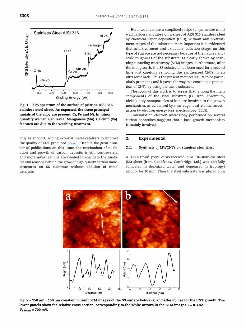
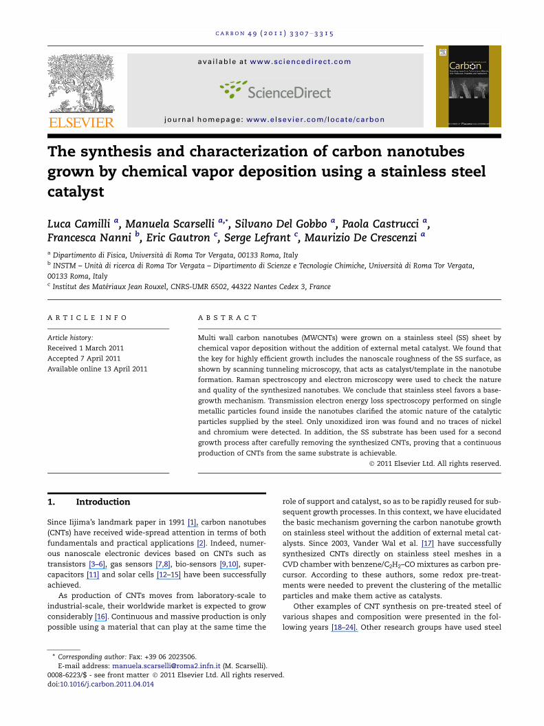
Fig. 1 – XPS spectrum of the surface of pristine AISI 316
stainless steel sheet. As expected, the three principal
metals of the alloy are present: Cr, Fe and Ni. In minor
quantity we can also reveal Manganese (Mn). Calcium (Ca)
features are due to the washing treatment.
3308 C A R B O N 4 9 ( 2 0 1 1 ) 3 3 0 7 – 3 3 1 5
only as support, adding external metal catalysts to improve
the quality of CNT produced [25–28]. Despite the great num-
ber of publications on this issue, the mechanism of nucle-
ation and growth of carbon deposits is still controversial
and more investigations are needed to elucidate the funda-
mental reasons behind the grow of high quality carbon nano-
structures on SS substrate without addition of metal
catalysts.
Fig. 2 – 150 nm · 150 nm constant current STM images of the SS
lower panels show the relative cross section, corresponding to
VSample = 700 mV.
Here, we illustrate a simplified recipe to synthesize multi
wall carbon nanotubes on a sheet of AISI 316 stainless steel
by chemical vapor deposition (CVD), without any pretreat-
ment stages of the substrate. More important it is evidenced
that acid treatment and oxidation–reduction stages on this
type of surface are not necessary because of the native nano-
scale roughness of the substrate, as clearly shown by scan-
ning tunneling microscopy (STM) images. Furthermore, after
the first growth, the SS substrate has been used for a second
time just carefully removing the synthesized CNTs in an
ultrasonic bath. Thus the present method results to be partic-
ularly promising and it paves the way to a continuous produc-
tion of CNTs by using the same substrate.
The focus of this work is to assess that, among the main
components of the steel substrate (i.e. iron, chromium,
nickel), only nanoparticles of iron are involved in the growth
mechanism, as evidenced by near edge local atomic investi-
gation by electron energy loss spectroscopy (EELS).
Transmission electron microscopy performed on several
carbon nanotubes suggests that a base-growth mechanism
is mainly involved.
2. Experimental
2.1. Synthesis of MWCNTs on stainless steel sheet
A 30 · 40 mm2 piece of as-received AISI 316-stainless steel
(SS) sheet (from Goodfellow Cambridge, Ltd.) was carefully
sonicated in deionized water and degreased in isopropyl
alcohol for 10 min. Then the steel substrate was placed on a
surface before (a) and after (b) use for the CNT growth. The
the white arrows in the STM images. I = 0.3 nA,

Fig. 3 – Histograms of the diameter of the nano-hills
obtained from STM images. Dotted line is the lognormal fit ;
the average size found is 6.5 ± 1 nm for the SS substrate
before (a) and 8.5 ± 1.3 nm after the growth (b).
C A R B O N 4 9 ( 2 0 1 1 ) 3 3 0 7 – 3 3 1 5 3309
molybdenum sample holder acting also as resistive heater
and inserted into an ultra high vacuum (UHV) chamber.
The pressure was brought up to 10�2 Torr by a rotary pump.
At this stage, argon gas (500 sccm) was inserted at 12 Torr and
then the heater was increased to about 730 �C. The sample
temperature was checked with an optical pyrometer. When
the substrate reached the desired temperature, acetylene
(C2H2) was introduced (200 sccm) in the chamber and CNTs
grew in dynamic condition, since the rotary pump was kept
in operation during the process. After 10 min of growth argon
gas (500 sccm) was inserted in chamber for 5 min.
2.2. Characterization of stainless steel substrate andMWCNTs
A STM/AFM (Omicron, Germany) system was used in UHV
(7 · 10�11 Torr) to analyze the SS sheet both before and after
the CNT growth, to investigate down to the nanometric scale
the substrate surface roughness. The measurements were
performed at room temperature in constant current mode
with I = 0.3 nA, VSample = 700 mV.
X-ray photoelectron spectroscopy (XPS) data were ac-
quired with a semi-imaging analyzer MAC2 (Riber Instru-
ments) operating in the constant pass energy mode (with
the total energy resolution of 1.1 eV) using a non-monochro-
matized Al Ka radiation source. The distance between the
sample and the anode was about 40 mm, the illumination
area was about 5 · 5 mm2 and the takeoff angle between the
sample surface and the photoelectron energy analyzer was
kept fixed at 45�. The energy scale with reference to the bind-
ing energy of the C1s was calibrated at 284.7 eV with respect
to the Fermi level.
Raman spectroscopy was also employed to characterize
the synthesized sample. The Raman spectra were obtained
by a micro-Raman setup equipped with Rayleigh scattering
micro imaging. The setup is made up of a Coherent Sabre
Ar+ laser, a Dilor triple monochromator equipped with LN2
cooled CCD (Horiba 3000C), confocal optics and a nanometric
piezo actuated positioning/scanning table. The confocal op-
tics allows a spatial resolution of �350 nm in the xy plane
and of �1 lm along the z-axis. The spectra was acquired
using an exciting laser wavelength of 514 nm in the backscat-
tering configuration z(x,x)-z.
The morphology and structure of the CNTs were examined
using a field emission gun scanning electron microscope
(FEG-SEM, Leo Supra 35) equipped with energy dispersive X-
ray (EDX) and a cold FEG Hitachi HF2000 transmission elec-
tron microscope (TEM) operated at 200 kV. In order to collect
images from the self-supported nanostructures, TEM samples
were prepared scratching with a razor blade the synthesis
product from the SS surface directly on a gold TEM grid (mesh
1000). Transmission EELS measurements performed on single
particles found inside the tubes were carried out with the
same TEM but with an accelerating voltage of 100 kV,
equipped with Gatan 666 parallel spectrometer. The energy
resolution of the spectra was estimated to be about 1.5 eV
measuring the full width at half-maximum of the zero loss
peak.
In order to demonstrate the possibility to recover and to re-
use the SS sheet after the growth stage, CNTs were removed
from the surface by sonication in isopropyl alcohol. Half of
the SS piece was treated with hydrochloric acid 32% in weight
(HCl) for 1 h, prior to be used for a second growth process.
3. Results and discussion
3.1. Surface atomic composition and morphology ofstainless steel sheet
XPS data (shown in Fig. 1) have been used to assess the
presence, on the stainless steel surface, of all the three
main metals (Fe, Cr and Ni) in the alloy. This analysis
showed that any segregation phenomena were not observed.
We also noticed the presence of Mn, as reported in the
nominal composition of the AISI 316 steel (1.5% atomic
composition). Traces of Ca have been found probably due
to the washing treatment.
We stress that the reported surface morphology has been
obtained without any surface pretreatment (any acid or other
physical–chemical removal of the first outer layers). The
height profile of the nanostructures is reported in the lower
part of Fig. 2a, showing a height distribution ranging from
3.0 nm to 4.5 nm. The presence of these hills reveals the na-
tive nanoscale substrate structure, constituted by small

Fig. 4 – (a and b) Low and high magnification SEM images of the MWCNTs synthesized directly on SS sheet. (c) Blow up of (b)
showing some capped CNTs with catalyst particle at the tip end (red arrows) and some uncapped CNTs (white arrows). (For
interpretation of the references to color in this figure legend, the reader is referred to the web version of this article.)
Fig. 5 – Raman spectrum of MWCNTs grown on SS sheet.
The D-band intensity is almost one third of G-band feature,
proving high structural quality of the sample. The arrow
shows the feature located at higher energy with respect to
the G band and it is characteristic of the formation of multi
walled structure.
3310 C A R B O N 4 9 ( 2 0 1 1 ) 3 3 0 7 – 3 3 1 5
islands which are essential (coupled to suitable thermody-
namic conditions) for carbon nanotube synthesis by chemical
vapor deposition [29,30]. This observation clearly shows that
any physical–chemical pretreatment of SS surface is not
necessary to create the morphology requested for the CNT
synthesis, contrary to a number of earlier studies [17,19,
21,22,24,27].
Once grown, the carbon nanotubes have been removed by
sonication and the SS surface was investigated with STM
again. Fig. 2b shows that the nano-hills are still present and
this observation explains why repetitive growths are possible
on stainless steel, as shown in the following and by others
[23]. We also performed a detailed statistical analysis of sev-
eral STM images collected on both substrates. The results ob-
tained are reported in Fig. 3. The average lateral size of the
nanostructures found is 6.5 ± 1 nm in the case of the SS sub-
strate before use and 8.5 ± 1.3 nm after the growth.
We conclude that the metallic composition and the sur-
face morphology of SS substrate favor in a straightforward
way the CNT synthesis as a natural and almost infinite source
of catalyst.
3.2. Carbon nanotube characterization
Fig. 4a and b reports SEM images of our synthesized nano-
structures showing that random-oriented CNTs are uniformly
grown on the SS sheet with very-high density. After only
10 min of acetylene exposure we estimated that the length
of the carbon nanotubes reaches 50 lm. Over the large SS area

Fig. 6 – TEM images showing the multi wall nature of CNTs grown on SS sheet. (a) Red arrows indicate uncapped CNTs. (b)
High resolution of a typical MWCNT with 23 walls. (For interpretation of the references to color in this figure legend, the
reader is referred to the web version of this article.)
Fig. 7 – HRTEM images illustrating the different observed morphologies: (a and b) two examples of a shoot-shaped catalytic
particle inside a tube; (c) the formation of the fullerene cap around the catalytic particle on the tip of a CNT; (d) a capped and (e)
an uncapped tube.
C A R B O N 4 9 ( 2 0 1 1 ) 3 3 0 7 – 3 3 1 5 3311
used, only few traces of carbonaceous nanostructures have
been detected. Fig. 4c is a blow up of Fig. 4b, showing a wide
distribution of tube diameters. Red arrows indicate small
bright catalyst particles located at the tip of the CNTs, while
white arrows the CNTs without caps. This finding will be
extensively explained below.
Raman spectrum of the as-grown CNTs is reported in
Fig. 5. The arrow shows the feature located at higher energy

Fig. 8 – Schematic depiction of growth process of the
MWCNTs on stainless steel. At the working temperature
(730 �C), the nano-hills on the stainless steel surface are in
liquid state, so the stretching force applied on them during
the formation of the CNT make them elongated and finally
broken into two parts. According to this model the tube
grows upward, leaving the nano-hill (or, at least, a part of it)
on the SS surface.
Fig. 9 – Typical EELS analysis performed on single metal
nanoparticle located inside a carbon nanotube. The
presence of Fe L2,3 features at around 710 eV energy loss
region revealed that it is made of pure iron. No chromium
and nickel atoms have been measured (due to the absence
of ionization edges at around 570 eV and 850 eV,
respectively) within the minimum detectable
concentrations. Also the oxygen K ionization edge resulted
to be absent, thus showing that iron nanoparticles are not
oxidized. This finding is confirmed by the intensity ratio
between Fe L3 and L2 ionization edges, as reported in the
inset, which amounts to about three [32].
Fig. 10 – EDX spectra of the stainless steel surface before
(blue curve) and after (red curve) the CNT growth. We
observe that among the main metallic elements (Fe, Cr and
Ni) of the steel alloy only iron can be detected within the
carbon nanotube network. (For interpretation of the
references to color in this figure legend, the reader is
referred to the web version of this article.)
3312 C A R B O N 4 9 ( 2 0 1 1 ) 3 3 0 7 – 3 3 1 5
with respect to the G band and it is characteristic of the for-
mation of multi walled structure. The intensity of the D-band,
generally attributed to the amount of structural defects, re-
sulted to be about one third of the G-band feature. This
strongly suggests that our carbon nanotubes are character-
ized by very few structural imperfections. The reported ratio
is similar to that obtained by Kim et al. [25] who have synthe-
sized CNTs on SS by water-assisted chemical vapor deposi-
tion with the addition of external metallic catalyst. It is
worth noting that this ratio is well lower than that we mea-
sured in case of MWCNTs synthesized with the same CVD
apparatus by using Fe catalyst [14] on a silicon substrate.
TEM images prove the multi walled nature of carbon nano-
tubes, as reported in Fig. 6. The average inner diameter (ID) of
the nanotubes resulted to be 9 ± 3 nm, while the outer diam-
eter (OD) was 19 ± 6 nm. Interestingly, we note that the ID va-
lue closely corresponds to the average size of nano-hills on
the SS surface evaluated from the statistical analysis
(8.5 ± 1.3 nm) reported in Fig. 3b.This is a direct evidence that
the native nanostructures of the SS act as catalyst/template
in the nanotube formation.
Fig. 6a shows also the presence of nanotubes without cap,
as indicated by white arrows, in agreement with SEM images
(see Fig. 4). In Fig. 6b is reported a high resolution TEM
(HRTEM) image of a typical MWCNT with 23 walls, pointing
up the high quality and good graphitization degree of the ob-
tained nanostructures.
Fig. 7a–e are HRTEM images of different morphologies ob-
served in our sample. In some cases we detected shoot-
shaped nanoparticles inside tubes (see Fig. 7a and b). The
explanation of this phenomenon was given by Chen et al.
[31] who suggested that the catalytic nanoparticles are in a

Fig. 11 – SEM images collected on the SS substrate after the second growth process; (a) as used and (b) chemically etched SS.
C A R B O N 4 9 ( 2 0 1 1 ) 3 3 0 7 – 3 3 1 5 3313
liquid state at working temperature (730 �C) and the stretch-
ing force causes them to elongate and finally break. In this
way the metallic nanoparticles are dragged by the tube during
growth, as schematically illustrated in Fig. 8. This observation
is a clear-cut proof of a base-growth mechanism for multi
wall carbon nanotube on SS substrate. In Fig. 7c we report
an example of the encapsulation of catalyst particles at the
top end of the CNT. It is evident the formation of the fullerene
shell around the particle, which will form the cap of the tube.
In our case we find no particles attached to the base of carbon
nanotubes in HRTEM images, but only inside them (Fig. 7a and
b) or at the tip (Fig 7c). We suggest that this is due to our pe-
culiar growth method that employs the whole SS sheet as cat-
alyst. The nano-hills that act as template for the CNT
formation are well adhering to the SS bulk underneath and
therefore are not stripped during the detachment of nano-
tubes, before the TEM analysis. In Fig. 7d and e we illustrate
the two cases that occur in the terminal part of tube: an un-
capped and a capped one. Probably, these morphologies are
possible because the nano-hills on the surface of SS sheet
have different average size and we suggest that the smallest
ones should favor the formation of the fullerene shell, while
the larger ones should lead to the open end. This finding dem-
onstrates that a wide number of situations can be achieved
from the described growth process.
Many EELS analyses (shown in Fig. 9), performed on single
nanoparticles inside the tubes with an electron probe smaller
than the particle, revealed that they are made of pure iron. No
nickel and chromium atoms have been detected within the
limits of the minimum detectable concentrations (about
0.5 wt.%).
The result is confirmed by EDX analysis (reported in
Fig. 10) performed on the pristine stainless steel (blue curve)
and on the as-grown carbon nanotube carpet (red curve). It
is worth noting the difference in the intensity of C-relative
peak in the two cases, proving the presence of a great num-
ber of produced MWCNTs. We observe that only iron feature
is detected on the whole network of the carbon nanostruc-
tures.
This finding has been already reported by Mordkovich
et al. [20] in the case of CNTs grown with Fe–Ni catalytic film
deposited on SS-304 substrate; thus, also in pristine SS-316,
the competition between these two metals in the CNT growth
process leads to total suppression of the catalytic activity of
nickel in favor of iron. This is one of the main results of our
investigation, because we know very well that both iron and
nickel (as well as cobalt) are the most used catalytic materials
for the synthesis of CNTs via chemical vapor deposition. At
present, we do not have a clear model to explain this impor-
tant issue in which the formation of carbon nanotubes occurs
only by extracting iron from the SS surface, leaving the other
metals unreacted on the surface (as schematically depicted in
Fig. 8). We suspect that our observation could be attributed to
the different diffusion kinetics of C atoms in iron or in nickel
lattice at the temperature utilized for the synthesis (730 �C).
Thus a theoretical explanation is needed to clarify this exper-
imental observation with the aim to understand the selective
catalyst action and extraction of a metal over all others of the
SS alloy.
Surprisingly, we observed that iron is not oxidized, as we
can clearly see from a careful analysis of the Fe L2,3 edge line
shapes [32] and from the total absence of any signal coming
from the oxygen K ionization edge (Fig. 9). From the near edge
features shown in the inset of Fig. 9 we estimated that the ra-
tio between L3 and L2 lines (white-line ratio) is very close to
the value reported in Ref. [32] for pure iron (ratio of about 3).
This is a clear hint of its metallic character, in fact any other
form of oxidized iron reports a statistical value of the ratio
much higher, ranging from 4.3 for FeO up to 5.1 for Fe2O3
[33]. Thus, the intercalation in the graphitic planes hinders
any oxidation process of these metal nanoparticles. This
observation could be of some interest for practical applica-
tions, such as magnetic recording [34] and bio-application
[35,36], where the use of pure iron is preferred to that of its
oxidized form.
SEM images were also collected on the CNT grown on a re-
used SS sheet as shown in Fig. 11.
At this point it is worth reminding that, after the first CNT
synthesis and complete removing cycle, only half of SS sheet
has been chemically etched before the second CNT growth.
No significant difference was revealed in the density and
quality of the carbon nanotube film on the two surface sides.
This proves that no further treatment is necessary to the steel
surface for reuse in the growth, as already discussed by
Baddour et al. [21].
4. Conclusions
We have reported a careful method to grow high quality
MWCNTs directly on stainless steel without any additional

3314 C A R B O N 4 9 ( 2 0 1 1 ) 3 3 0 7 – 3 3 1 5
metal catalyst and any surface pretreatment. The method
allows to produce large quantities of CNTs with a very sim-
ple procedure and cheap materials so that we believe a
mass production could be implemented in a near future.
In fact, pieces of steels heated in hydrocarbon atmosphere
are just necessary to obtain long and almost defect free
nanotubes, as supported by Raman spectroscopy. The meth-
od allows an easy and quick reuse of the same SS substrate
without any additional process, apart a careful removal of
synthesized carbon nanotubes. The key role of the nano-
structured surface character of the stainless steel has been
assessed by STM investigation, revealing the presence of
small islands of the same order of magnitude of the internal
channel of the produced CNTs. The native metallic surface
morphology is the principal ingredient that excludes the
addition of external metallic catalyst. A surprising discover
of our EELS investigation performed above the L2 and L3 ion-
ization edges of Fe, Ni and Cr is that inside the nanotube we
only detected unoxidized iron nanoparticles. This finding is
extremely important to understand the thermodynamic of
the interaction of carbon atoms, coming from gas feedstock
(i.e. acetylene), with stainless steel substrate surface. We re-
ported evidence that the catalytic activity of nickel is com-
pletely suppressed even though it is well known that
nickel is an efficient catalyst for CNTs growth through
CVD method. Therefore, further experiences are still needed
to investigate the full role of single metallic components
present into the SS alloy. On this last point, a theoretical
investigation of the growth mechanism is highly expected
to explain the selectivity of carbon nanotubes to grow on
iron instead on nickel.
Acknowledgements
This work was supported by the French-Italian Galileo 2009–
2010 project. The Italian authors acknowledge the financial
support of the Queensland Government smart futures fund
National and International Research Alliances Program (NIR-
AP): Solar powered nano-sensors for data acquisition and sur-
veying in remote areas‘, ABN 83 791 724 622. We are grateful to
Dr. M. Salvato for thickness measurements of the samples.
R E F E R E N C E S
[1] Iijima S. Helical microtubules of graphitic carbon. Nature1991;354:56–8.
[2] Baughman RH, Zakhidov AA, de Heer WA. Carbon nanotubes– the route toward application. Science 2002;297(5582):787–92.
[3] Bachtold A, Hadley P, Nakanishi T, Dekker C. Logic circuitswith carbon nanotube transistors. Science2001;294(5545):1317–20.
[4] Javey A, Guo J, Wang Q, Lundstrom M, Dai HJ. Ballistic carbonnanotube transistors. Nature 2003;424:654–7.
[5] Javey A, Guo J, Farmer DB, Wang Q, Yenilmez E, Gordon RG,et al. Self-aligned ballistic molecular transistors andelectrically parallel nanotube arrays. Nano Lett2004;4(7):1319–22.
[6] Herrero PJ, van Dam JA, Kouwenhoven LP. Quantumsupercurrent transistors in carbon nanotubes. Nature2006;439:953–6.
[7] Modi A, Koratkar N, Lass E, Wei BQ, Ajayan PM. Miniaturizedgas ionization sensors using carbon nanotubes. Nature2003;424:171–4.
[8] Qureshi A, Kang WP, Davidson JL, Gurbuz Y. Review oncarbon-derived, solid-state, micro and nano sensors forelectrochemical sensing applications. Diamond Relat Mater2009;18(12):1401–20.
[9] Sanchez-Pomales G, Santiago-Rodriguez L, Cabrera CR. DNA-functionalized carbon nanotubes for biosensing applications.J Nanosci Nanotechnol 2009;9(4):2175–88.
[10] Oh J, Yoo S, Chang YW, Lim K, Yoo KH. Carbon nanotube-based biosensor for detection hepatitis B. Curr Appl Phys2009;9(4):229–31.
[11] Futaba DN, Hata K, Yamada T, Hiraoka T, Hayamizu Y,Kakudate Y, et al. Shape-engineerable and highly denselypacked single-walled carbon nanotubes and their applicationas super-capacitor electrodes. Nat Mater 2006;5(12):987–94.
[12] Lee JU. Photovoltaic effect in ideal carbon nanotube diodes.Appl Phys Lett 2005;87(7):073101–3.
[13] Wei J, Jia Y, Shu Q, Gu Z, Wang K, Zhuang D, et al. Double-walled carbon nanotube solar cells. Nano Lett2007;7(8):2317–21.
[14] Castrucci P, Tombolini F, Scarselli M, Speiser E, Del Gobbo S,Richter W, et al. Large photocurrent generation inmultiwall carbon nanotubes. Appl Phys Lett2006;89(25):253107–9.
[15] El Khakani MA, LeBorgne V, Aissa B, Rosei F, Scilletta C,Speiser E, et al. Photocurrent generation in randomnetworks of multiwall-carbon-nanotubes grown by an ‘‘alllaser’’ process. Appl Phys Lett 2009;95(8):083114–6.
[16] Ebbesen TW, Ajayan PM. Large-scale synthesis of carbonnanotubes. Nature 1992;358(6383):220–2.
[17] Vander Wal RL, Hall LJ. Carbon nanotubes synthesis uponstainless steel meshes. Carbon 2003;41(4):659–72.
[18] Park D, Kim YH, Lee JK. Synthesis of carbon nanotubes onmetallic substrates by a sequential combination of PECVDand thermal CVD. Carbon 2003;41(5):1025–9.
[19] Karwa M, Iqbal Z, Mitra S. Scaled-up self assembly of carbonnanotubes inside long stainless steel tubing. Carbon2006;44(7):1235–42.
[20] Mordkovich VZ, Dolgova EA, Karaeva AR, Kharitonov DN,Maslov IA, Kamenev AA, et al. Synthesis of carbonnanotubes by catalytic conversion of methane: competitionbetween active components of catalyst. Carbon2007;45(1):62–9.
[21] Baddour CE, Fadlallah F, Nasuhoglu D, Mitra R, Vandsburger L,Meunier JL. A simple thermal CVD method for carbonnanotube synthesis on stainless steel 304 without theaddition of an external catalyst. Carbon 2009;47(1):313–8.
[22] Masarapu C, Wei B. Direct growth of aligned multiwalledcarbon nanotubes on treated stainless steel substrates.Langmuir 2007;23(17):9046–9.
[23] Baddour CE, Upham DC, Meunier JL. Direct and repetitivegrowth cycles of carbon nanotubes on stainless steelparticles by chemical vapor deposition in a fluidized bed.Carbon 2010;48(9):2644–73.
[24] Nguyen XH, Lee YB, Lee CH, Lim D-S. Synthesis of sea urchin-like particles of carbon nanotubes directly grown on stainlesssteel cores and their effect on the mechanical properties ofpolymer composites. Carbon 2010;48(10):2910–6.
[25] Kim B, Chung H, Chu KS, Yoon HG, Lee CJ, Kim W. Synthesisof vertically-aligned carbon nanotubes on stainless steel bywater-assisted chemical vapor deposition andcharacterization of their electrochemical properties. SynthMet 2010;160(7–8):584–7.
[26] Duy DQ, Kim HS, Yoon DM, Lee KJ, Ha JW, Hwang YG, et al.Growth of carbon nanotubes on stainless steel substrates byDC-PECVD. Appl Surf Sci 2009;256(4):1065–8.

C A R B O N 4 9 ( 2 0 1 1 ) 3 3 0 7 – 3 3 1 5 3315
[27] Martinez-Hansen V, Latorre N, Royo C, Romeo E, Garcia-Bordeje E, Monzon A. Development of aligned carbonnanotubes layers over stainless steel mesh monoliths. CatalToday 2009;147(Supplement 1):S71–5.
[28] Hiraoka T, Yamada T, Hata K, Futaba DN, Kurachi H, UemuraS, et al. Synthesis of single- and double-walled carbonnanotube forests on conducting metal foils. J Am Chem Soc2006;128(41):13338–9.
[29] Kong J, Cassell AM, Dai H. Chemical vapor deposition ofmethane for single-walled carbon nanotubes. Chem PhysLett 1998;292(4–6):567–74.
[30] Rodriguez NMA. Review of catalytically grown carbonnanofibers. J Mater Res 1993;8(3):3233–50.
[31] Chen X, Wang R, Xu J, Yu D. TEM investigation on the growthmechanism of carbon nanotubes synthesized by hot-filament chemical vapor deposition. Micron2004;35(6):455–60.
[32] Leapman RD, Grunes LA, Fejes PL. Study of the L2, 3 edges inthe 3d transition metals and their oxides by electron-energy-loss spectroscopy with comparisons to theory. Phys Rev B1982;26(2):614–35.
[33] Schmid HK, Mader W. Oxidation states of Mn and Fe invarious compound oxide systems. Micron2006;37(5):426–32.
[34] Kuo CT, Lin CH, Lo AY. Feasibility studies of magnetic particle-embedded carbon nanotubes for perpendicular recordingmedia. Diamond Relat Mater 2003;12(3–7):799–805.
[35] Monch I, Leonhardt A, Meye A, Hampel S, Kozhuharova-Koseva R, Elefant D, et al. Synthesis and characteristics of Fe-filled multi-walled carbon nanotubes for biomedicalapplication. J Phys: Conf Ser 2007;61:820–4.
[36] Costa S, Borowiak-Palen E, Bachmatiuk A, Rummeli MH,Gemming T, Kalenczuk RJ. Filling of carbon nanotubes forbio-applications. Phys Stat Sol b 2007;244(11):4315–8.


![1,10Dihydro3,9-dimethylpyrazolo[3,4- a ]carbazole](https://static.fdokumen.com/doc/165x107/63225bc364690856e1092115/110dihydro39-dimethylpyrazolo34-a-carbazole.jpg)