Symbolic equation for linear analog electrical circuits using ...
10
Symbolic equation for linear analog electrical circuits using Matlab ZOLTAN ERDEI, LUIZA ALEXANDRA DICSO, LIVIU NEAMT, OLIVER CHIVER Department Electrical Engineering North University of Baia Mare Str. Victor Babes Nr. 62/A, 430083 ROMANIA [email protected] Abstract: - In this paper is presented a program which generates the modified nodal equation for electric analog circuits in a symbolic, partial symbolic and numerical mode. The program is an application, made in the environment of the program MATLAB version 7.1, which has a powerful symbolic math toolbox. MATLAB is a high-performance software package dedicated for numerical analysis and graphic representations in engineering applications. In this paper we try to explore the capabilities of this program in symbolic domain. Key-Words: - analog circuits, circuit functions, symbolic equations, Matlab, netlist, modified nodal analysis. 1 Introduction The modified nodal methods have been implemented in a program on a Pentium Dual Core computer compatible to obtain symbolic forms, partly symbolic or numerical equations for electronic linear analog circuits. Between the input gate and the output one specified by the user, any of the four types of circuit functions (transfer impedance - Zei, admittance transfer function - Yei, voltage transfer factor (amplifier) - Aei and current transfer factor (amplifier) – Bei) for linear analog electric circuits around a functionary point. Starting from the description of the circuit through to a file- type input netlist, according to the window shown in figure 1, the following capabilities: - generates symbolic, partly symbolic or numerical equations using modified nodal analysis for linear electrical circuits; - generates symbolic form of the extensive matrix of the system equations and determines the symbolic solution, partly symbolic or numerical Fig.1 Application window WSEAS TRANSACTIONS on CIRCUITS and SYSTEMS Zoltan Erdei, Luiza Alexandra Dicso, Liviu Neamt, Oliver Chiver ISSN: 1109-2734 493 Issue 7, Volume 9, July 2010
-
Upload
khangminh22 -
Category
Documents
-
view
0 -
download
0
Transcript of Symbolic equation for linear analog electrical circuits using ...

Symbolic equation for linear analog electrical circuits using Matlab
ZOLTAN ERDEI, LUIZA ALEXANDRA DICSO, LIVIU NEAMT, OLIVER CHIVER
Department Electrical Engineering North University of Baia Mare
Str. Victor Babes Nr. 62/A, 430083 ROMANIA
Abstract: - In this paper is presented a program which generates the modified nodal equation for electric analog circuits in a symbolic, partial symbolic and numerical mode. The program is an application, made in the environment of the program MATLAB version 7.1, which has a powerful symbolic math toolbox. MATLAB is a high-performance software package dedicated for numerical analysis and graphic representations in engineering applications. In this paper we try to explore the capabilities of this program in symbolic domain. Key-Words: - analog circuits, circuit functions, symbolic equations, Matlab, netlist, modified nodal analysis.
1 Introduction The modified nodal methods have been implemented in a program on a Pentium Dual Core computer compatible to obtain symbolic forms, partly symbolic or numerical equations for electronic linear analog circuits. Between the input gate and the output one specified by the user, any of the four types of circuit functions (transfer impedance - Zei, admittance transfer function - Yei, voltage transfer factor (amplifier) - Aei and current
transfer factor (amplifier) – Bei) for linear analog electric circuits around a functionary point. Starting from the description of the circuit through to a file-type input netlist, according to the window shown in figure 1, the following capabilities: - generates symbolic, partly symbolic or
numerical equations using modified nodal analysis for linear electrical circuits;
- generates symbolic form of the extensive matrix of the system equations and determines the symbolic solution, partly symbolic or numerical
Fig.1 Application window
WSEAS TRANSACTIONS on CIRCUITS and SYSTEMSZoltan Erdei, Luiza Alexandra Dicso, Liviu Neamt, Oliver Chiver
ISSN: 1109-2734 493 Issue 7, Volume 9, July 2010

to the circuit system; Data entry is a set of lines describing nl circuit branch. Each branch of the circuit is described by a proper letter which indicates the type of circuit elements, the first node, final node, the nominal value and the value of the tolerance. In the case of controlled sources we should also introduce nodes of command branch. The netlist is similar to those described in the program SPICE.
2 Modified Nodal Analysis (MNA) To solve the circuit and obtain the desired circuit function we use the modified nodal analysis. In the modified nodal analysis the circuit matrix is obtained by the augmentation of the nodal conductance (admittance) matrix corresponding to the NA- compatible circuit elements with additional rows and columns for non-NA-compatible circuit elements. The circuit equations in operational corresponding to the modified nodal analysis method, have the following form:
,)(
)(
)(
)(
)()(
)()( 1,1
,1,
,11,1
=
⋅
−−
−
−−−
s
s
s
s
ss
ss
m
nsc
m
n
mmnm
mnnn
E
I
I
V
ZA
BY(1)
Where: )(1,1 snn −−Y - is the admittance matrix
corresponding to the n-1 independent nodes; )(,1 smn−B is an (n-1)xm matrix and it contains the
elements -1, 0, +1 and the current gains of the CCCS’s; )(1, snm −A is an mx(n-1) matrix
containing the elements -1, 0, +1 and the voltage gains of the VCVS’s; )(, smmZ is a mxm matrix
having the transfer impedances of the CCVS’s; )(1 sn−V is node voltage vector corresponding to the
n-1 independent nodes. The vector )(smI represents the current vector corresponding to
the non-NA compatible circuit branches and it has the following structure:
( ) ( ) ( ) ( ) ( )[ ] ,)(,)(,)(,)(,)()( tttttt ssssss Ljeeem CCcIIIIII = (2)
where : ( )t)(seI is the ideal voltage source current
vector; ( )t)(sceI the controlled (output) branch
current vector of all controlled voltage sources;
( )t)(sCeI the controlling (input) branch current
vector of the CCVS’s; ( )t)(sCj
I the controlling
branch current vector of the CCCS’s. The vectors )(1, snsc −I and )(smE represent the contributions of
the excitation sources (independent current and voltage sources).
3 Description of the application
To explain and understand this application we consider the following circuit (figure 2). This
Fig. 2 Lowpass Sallen Key filter
WSEAS TRANSACTIONS on CIRCUITS and SYSTEMSZoltan Erdei, Luiza Alexandra Dicso, Liviu Neamt, Oliver Chiver
ISSN: 1109-2734 494 Issue 7, Volume 9, July 2010

application describes how to use a lowpass Sallen-Key filter with a dual supply voltage. The circuit provides a Butterworth response with a 30MHz bandwidth, and is ideal for video-reconstruction filtering in HDTV applications. In HDTV applications, lowpass filters are used for reconstruction of RGB and component video (Y, Pb, and Pr) signals. They are placed following the video DAC to remove the higher frequency replicas of the signals, as well as before the ADC for anti-aliasing. Figure 2 shows a one-channel, dual-supply configuration incorporating the MAX4382. It is a three-pole, Sallen-Key Butterworth lowpass filter, in which the current DAC generates the video signal, and the resistor (RL) sets the amplitude. With the MAX4382, the RL, R1, R2, C1, and C2 form a two-pole, Sallen-Key lowpass filter having a gain of 2. The driving load (75Ω) at the output, plus RT and Cp, sets the real pole. In the Figure 2 circuit, the -3dB bandwidth is about 30MHz. The attenuation is approximately 14dB at 44.25MHz, and 28dB at 74.25MHz. The group delay is roughly 6.5ns. If the current DAC load is different than 75Ω, just use the following relationship to set the value of R1: R1 + RL = 150Ω. For RL greater than 150Ω, C1, C2, R1, and R2 will need to be adjusted. The input file for this example has the following structure:
6 R1 1 0 75 0.02 R2 1 2 75 0.02 R3 2 3 150 0.02 R4 5 0 590 0.02 R5 6 5 590 0.02 R6 6 4 75 0.02 Rf 3 5 100000 0.00001 C1 3 0 0.000000000022 0.1 C2 2 6 0.000000000022 0.1 C3 4 0 0.000000000120 0.1 E1 1 0 1 0.1 G1 3 5 0 6 1000000 The first row from this net list file represents the number of nodes of the circuit. After that each line describes a circuit element which is defined by the first letter (ex. R for resistor, C for capacitor etc). This application, in order to solve the circuit with symbolic method, needs to contain the following instruction lines, particularized for each circuit element – in the example we have the code for resistors. for i = 1:n %daca avem resistor if (findstr(latura(i).tip, 'R') == 1) nr_r_k = nr_r_k + 1; k1 = int8(str2double(num2str(latura(i).ni))); k2 = int8(str2double(num2str(latura(i).nf))); if ((k1 > 0) & (k2 > 0)) exp1 = [A(k1, k1) '1/' latura(i).tip]; exp2 = [A(k1, k2) '-1/' latura(i).tip]; exp3 = [A(k2, k1) '-1/' latura(i).tip]; exp4 = [A(k2, k2) '1/' latura(i).tip]; str1 = sym(exp1); str2 = sym(exp2); str3 = sym(exp3); str4 = sym(exp4); C(k1, k1) = C(k1, k1) + str1; C(k1, k2) = C(k1, k2) + str2; C(k2, k1) = C(k2, k1) + str3; C(k2, k2) = C(k2, k2) + str4;
−
−
=
001-A0A00
00000001
10C2*s+1/R6+1/R51/R5-1/R6-0C2*s-0
001/R5-1/Rf+1/R5+1/R401/Rf-00
001/R6-0C3*s+1/R6000
0001/Rf-0C1*s+1/Rf+1/R31/R3-0
00C2*s-001/R3-C2*s+1/R3+1/R21/R2-
0100001/R2-1/R2+1/R1
Aei
WSEAS TRANSACTIONS on CIRCUITS and SYSTEMSZoltan Erdei, Luiza Alexandra Dicso, Liviu Neamt, Oliver Chiver
ISSN: 1109-2734 495 Issue 7, Volume 9, July 2010

elseif (k1 > 0) exp1 = [A(k1, k1) '1/' latura(i).tip]; str1 = sym(exp1); C(k1,k1) = C(k1, k1) + str1; elseif (k2 > 0) exp4 = [A(k2, k2) '1/' latura(i).tip]; str4 = sym(exp4); C(k2, k2) = C(k2, k2) + str4; end The A coefficient matrix obtained with the program for this example will be as above. The admittance transfer function for this example in a symbolic form: Yei=GA*(R5+R4)/(1+s*C3*R6)/(R4*R5+R5*Rf+R4*Rf+R5*R3+R5*s*C2*R2*R3-R2*R5*GA*Rf*s*C2+R2*R5*Rf*s*C2+R5*Rf*s*C1*R3+ R2*R5*Rf*s*C1+R2*R5*Rf*s^2*C1*R3*C2+R2*R5+R2*Rf*R4*s*C2+Rf*R4*s*C1*R3+R2*Rf*R4*s*C1+R2*Rf*R4*s^2*C1*R3*C2+R2*R4*s*C2*R3+R4*R3+R2*R4+GA*Rf*R4+R2*R5*s*C2*R4+GA*Rf*s*C1*R3*R4+R5*s*C1*R3*R4+R2*GA*Rf*s*C1*R4+R2*R5*s*C1*R4+R2*GA*Rf*s^2*C1*R3*C2*R4+R2*R5*s^2*C1*R3*C2*R4)*Rf*E1
Fig. 3 Waveform for lowpass Sallen-Key filter
In fig. 3 is represented the output waveform for Lowpass Sallen-Key filter obtained with this Matlab application after replacing symbolic values with nominal ones.
4 Examples of applications Bandpass Sallen-Key filter The parameter of this filter is Q of 10 and
WSEAS TRANSACTIONS on CIRCUITS and SYSTEMSZoltan Erdei, Luiza Alexandra Dicso, Liviu Neamt, Oliver Chiver
ISSN: 1109-2734 496 Issue 7, Volume 9, July 2010
−
+++
+++++
=
00100
0000001
000
0
0
AA
1/R51/R41/Rf1/R5-1/Rf-0
101/R5-1/R51/R201/R2-
001/Rf-01/Rf1/R3C2*sC2*s-
0001/R2-C2*s-C2*sC1*s1/R21/R11/R1-
010001/R1-1/R1
Aei
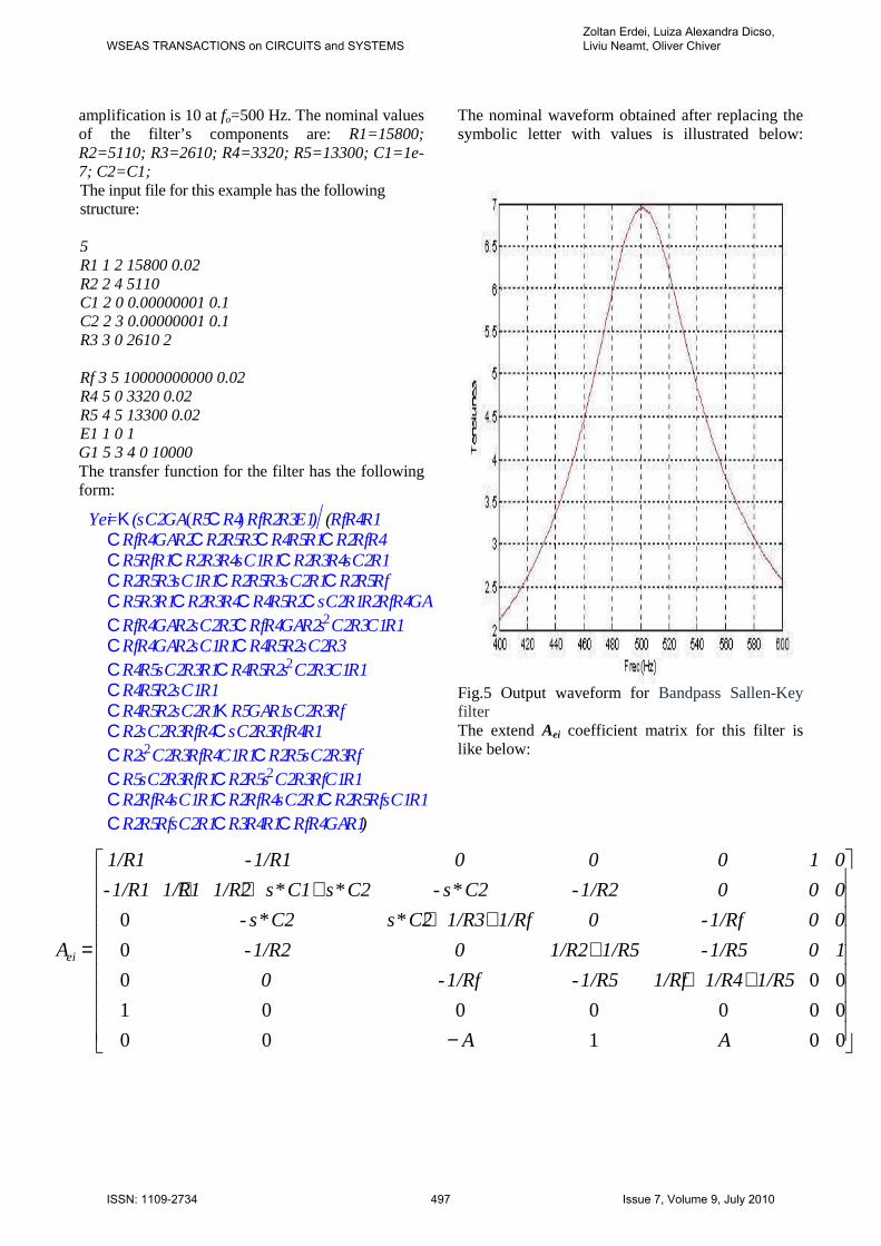
amplification is 10 at fo=500 Hz. The nominal values of the filter’s components are: R1=15800; R2=5110; R3=2610; R4=3320; R5=13300; C1=1e-7; C2=C1; The input file for this example has the following structure: 5 R1 1 2 15800 0.02 R2 2 4 5110 C1 2 0 0.00000001 0.1 C2 2 3 0.00000001 0.1 R3 3 0 2610 2 Rf 3 5 10000000000 0.02 R4 5 0 3320 0.02 R5 4 5 13300 0.02 E1 1 0 1 G1 5 3 4 0 10000 The transfer function for the filter has the following form:
The nominal waveform obtained after replacing the symbolic letter with values is illustrated below:
Fig.5 Output waveform for Bandpass Sallen-Key filter The extend Aei coefficient matrix for this filter is like below:
Yei=K (s C2 GA (R5CR4) Rf R2 R3 E1) (Rf R4 R1CRf R4 GA R2CR2 R5 R3CR4 R5 R1CR2 Rf R4CR5 Rf R1CR2 R3 R4 s C1 R1CR2 R3 R4 s C2 R1CR2 R5 R3 s C1 R1CR2 R5 R3 s C2 R1CR2 R5 RfCR5 R3 R1CR2 R3 R4CR4 R5 R2Cs C2 R1 R2 Rf R4 GACRf R4 GA R2 s C2 R3CRf R4 GA R2 s2 C2 R3 C1 R1CRf R4 GA R2 s C1 R1CR4 R5 R2 s C2 R3CR4 R5 s C2 R3 R1CR4 R5 R2 s2 C2 R3 C1 R1CR4 R5 R2 s C1 R1CR4 R5 R2 s C2 R1K R5 GA R1 s C2 R3 RfCR2 s C2 R3 Rf R4Cs C2 R3 Rf R4 R1CR2 s2 C2 R3 Rf R4 C1 R1CR2 R5 s C2 R3 RfCR5 s C2 R3 Rf R1CR2 R5 s2 C2 R3 Rf C1 R1CR2 Rf R4 s C1 R1CR2 Rf R4 s C2 R1CR2 R5 Rf s C1 R1CR2 R5 Rf s C2 R1CR3 R4 R1CRf R4 GA R1)
WSEAS TRANSACTIONS on CIRCUITS and SYSTEMSZoltan Erdei, Luiza Alexandra Dicso, Liviu Neamt, Oliver Chiver
ISSN: 1109-2734 497 Issue 7, Volume 9, July 2010

In order to be sure that our application generates correct symbolic equation, and does not introduce some deviation in the comportment of the circuits, we have simulated the same circuit with the same nominal values in ORCAD program, and we obtained the following waveform which is similar, if not identical, with the one obtained with our algorithm.
Fig. 6 Output waveform from ORCAD simulation
Bandpass Delyiannis filter The input data of this bandpass filter are: f0 = 500 Hz; Q = 20; R1 = 4.93K; R2 = 205K; Ra = 10K; Rb = 252K; C1 = 0.01uF; C2 = 0.01uF The input file for this filter has the following structure: 5 R1 1 2 4930 0.02 R2 3 4 205000 0.02 C1 2 3 0.000001 0.1 C2 2 4 0.00000001 0.1 R5 3 5 10000 0.2 R3 4 5 252000 0.2 R4 5 0 10000 0.2 E1 1 0 1 0.1 G1 3 5 4 0 1000000 The transfer function for the filter has the following form:
WSEAS TRANSACTIONS on CIRCUITS and SYSTEMSZoltan Erdei, Luiza Alexandra Dicso, Liviu Neamt, Oliver Chiver
ISSN: 1109-2734 498 Issue 7, Volume 9, July 2010

−
++++
++++
=
00100
0000001
000
0
0
AA
1/R31/R41/R51/R3-1/R5-0
101/R3-1/R3C2*s1/R21/R2-C2*s-
001/R5-1/R2-1/R5C1*s1/R2C1*s-
000C2*s-C1*s-C2*sC1*s1/R11/R1-
010001/R1-1/R1
Aei
Yei=(s C1 GA (R4CR3) R5 R2 E1) (GA R3 R5CR5 R4 s2 C1 R1 R2 C2K R2 R5 s C1 R4 GACR4 R5CR3 R4CR5 R3CR4 R2CR2 R3Cs C1 R1 R2 R4Cs C2 R1 R2 R4CR4 R5 s C2 R1Cs C1 R1 R2 R3Cs C2 R1 R2 R3CR5 R3 s C2 R1CR4 R5 R2 s C1CR2 R3 R4 s C1CR2 R5 R3 s C1CR4 R5 s C1 R1CR3 R4 s C1 R1CR5 R3 s C1 R1Cs2 C1 R1 R2 C2 R3 R4CR2 R5 R3 s2 C1 GA C2 R1CGA R3 R5 s C2 R1CGA R3 R5 s C1 R1CR5 R3 s2 C1 R1 R2 C2CR3 R4 s C2 R1)
The nominal waveform obtained after replacing the symbolic letter with values is illustrated below:
Fig. 8 Output waveform for bandpass Delyiannis
filter
The extend Aei coefficient matrix for this filter is as above. In order to be sure that our application generates correct symbolic equation, and does not introduce some deviation in the comportment of the circuits, we have simulated the same circuit with the same nominal values in ORCAD program, and we obtained the following waveform which is similar, if not identical, with the one obtained with our algorithm.
Fig. 9 Output waveform from ORCAD simulation
WSEAS TRANSACTIONS on CIRCUITS and SYSTEMSZoltan Erdei, Luiza Alexandra Dicso, Liviu Neamt, Oliver Chiver
ISSN: 1109-2734 499 Issue 7, Volume 9, July 2010

5 Conclusion The main advantage of the MNA method is that the contributions of all individual circuit elements can be inserted directly in appropriate places in (1), independently of whether the primary variable of a particular element is a voltage or a current. MNA method associated with an efficient nod tearing leads to an important reduction in computing time and to an increase of the accuracy. This is a new software environment that allows the schematic representation, analysis and design for linear analog circuits. This application is very useful in circuits design because is dedicated only for circuit analysis and combined with the power of Matlab platform we can test very complex circuits. Next steps are to develop this application with new capabilities like tolerance analysis. Programs like ORCAD have limited number of circuits nodes that they can solve. The speed of this application it s not the main issue only the size of the circuit analysis it’s important
6 Instruction lines function tolerefectfin % clear; if nargin<1, action='start'; end; %coordonatele ferestrei grafice si a axelor pe ecran ps=0.01; %distanta ferestrei fata de stanga pj=0.3; %distanta ferestrei fata de jos lg=0.98; %lungimea ferestrei hg=0.65; %inaltimea ferestrei global DISP global maximuri global count count=1; maximuri(count)=0; DISP=1; S=brighten([[zeros(8,2) (3:10)'/10]; prism(56)],1/3); if strcmp (action, 'start'), clf reset; set(gcf,'Units','normalized','backingstore','off','color',...
'blue','NumberTitle','off','colormap',S,... 'Position',[.01 .25 .98 .65],... 'Name','ANALIZATOR de TOLERANTA a CIRCUITELOR ELECTRICE ANALOGICE'); %colormenu; end; n_semn=1; %numarul de tipuri de semnale n_buts=n_semn+1; %numarul de butoane semnal+inchidere n_butr=4; %numarul de butoane pentru reprezentari n_but=n_buts+n_butr+3; % numarul de butoane %echivalente (+spatiile) %se plaseaza butoanele meniului in partea stinga h_g1=1-(n_but+1)*.01; %inaltimea echivalenta pentru butoane h_but=.9/n_but; %inaltimea butonului l_but=0.27; %lungimea butonului d_s1=.01; %distanta fata de marginea din stanga d_j1=.01; %distanta fata de marginea de jos %se pune butonul de inchidere "stop" pos = [d_s1 d_j1*.5 l_but h_but]; %pozitia butonului %f=figure('Visible','off','Position',[360,500,450,350]); hc1 = uicontrol (gcf, 'units','normal','pos',pos,... 'String','STOP','Callback',@stop_buton_Callback); %pos = [d_s1 (h_but*(1+n_butr+3)+d_j1)+.015 l_but h_but-.02]; hincarca=uicontrol(gcf,'units','normal','Style','pushbutton','String','Incarca circuit','Position',[d_s1 (h_but*6+d_j1) l_but .95*h_but],... 'Callback',@incarcabutton_Callback); hfunctie=uicontrol('Style','pushbutton','units','normal','String','Incarca functie','Position',[d_s1 (h_but*5+d_j1) l_but .95*h_but],... 'Callback',@functiebutton_Callback); harunca=uicontrol('Style','pushbutton','units','normal','String','grafic','Position',[d_s1 (h_but*4+d_j1) l_but .95*h_but],... 'Callback',@aruncabutton_Callback);
WSEAS TRANSACTIONS on CIRCUITS and SYSTEMSZoltan Erdei, Luiza Alexandra Dicso, Liviu Neamt, Oliver Chiver
ISSN: 1109-2734 500 Issue 7, Volume 9, July 2010

hgauss = uicontrol (gcf, 'units','normal','position',[d_s1 (h_but*3+d_j1) l_but .95*h_but],... 'String','GAUSS','Callback',@distributiebutton_Callback); hsemnal = uicontrol (gcf, 'units','normal','position',[d_s1 (h_but*2+d_j1) l_but .95*h_but],... 'String','semnal','Callback',@semnalbutton_Callback); hsterge = uicontrol (gcf, 'units','normal','position',[d_s1 (h_but*1+d_j1) l_but .95*h_but],... 'String','sterge','Callback',@stergebutton_Callback); ha=axes('Units','pixels','Position',[500,50,500,485]); %global SD_AXIS %SD_AXIS= axes('Position',[1.35*l_but .15 (1-1.5*l_but) .75]); %axis off %set(SD_AXIS,'Position',[1.35*l_but .15 (1-1.5*l_but) .75],... % 'XColor',[1 0 0],'YColor',[1 0 0],'ZColor',[1 0 0]) % get(SD_AXIS) %ha=axes('Units','pixels','Position',[50,95,200,185]); rect=[d_s1 ((n_but)*h_but+d_j1) (l_but/2) h_but-.06]; hfrecin=uicontrol('Style','text','units','normal','String','Frecv. inceput','Position',rect); hf1=uicontrol('Style','edit','String','0','units','normal','Position',[d_s1 ((n_but)*h_but+d_j1-0.05) (l_but/2) h_but-.06]); hfrecfin=uicontrol('Style','text','units','normal','String','Frecv. fin','Position',[d_s1+l_but/2+.01 ((n_but)*h_but+d_j1) (l_but/2) h_but-.06]); hf2=uicontrol('Style','edit','units','normal','String','1','Position',[d_s1+l_but/2+.01 ((n_but)*h_but+d_j1)-0.05 (l_but/2) h_but-.06]); %set(f,'Name','Efect tolerantza'); set([hincarca,harunca,hfunctie,hfrecin,hf1,ha,hfrecfin,hf2,hgauss,hsemnal,hsterge],'Units','normalized');
latura = struct('tip', '', 'ni',, 'nf',, 'valoare',, 'toler', ); val(1)=0; nod1(1)=0; nod2(1)=0; frec=[]; functietran=['']; old=-1; nrlaturi=0; y=[]; hold on; % set(f,'Visible','on') mx=['']; function incarcabutton_Callback(source,eventdata) [filename,pathname]=uigetfile('*.cir'); if isequal(filename,0) disp('Utilizatorul a ales Cancel') else disp(['Utilizatorul a ales',fullfile(pathname,filename)]) %open(file) fid=fopen(fullfile(pathname,filename),'r'); sir=fgetl(fid); [mx, sir] = strtok(sir); nm = str2num(mx) k=1; %nm linii matrice while 1 sir=fgetl(fid); if ~ischar(sir), break, end [mx,sir]=strtok(sir); latura(k).tip=mx; [mx,sir]=strtok(sir); latura(k).ni=str2num(mx); [mx,sir]=strtok(sir); latura(k).nf=str2num(mx);
WSEAS TRANSACTIONS on CIRCUITS and SYSTEMSZoltan Erdei, Luiza Alexandra Dicso, Liviu Neamt, Oliver Chiver
ISSN: 1109-2734 501 Issue 7, Volume 9, July 2010

References: [1] R. R. Boyd , Tolerance analysis of Electronic Circuits using Matlab, CRC Press, Washington 2002. [2] A. E. Schwarz, Computer-aided design of microelectronic circuits and systems, Academic Press, London, 1987. [3] H. J. Orchard, G. C. Temes, “Filter design using transformed variables”, CT, 15, Dec. 1968. [4] Lucia Dumitriu, M. Iordache, Teoria moderna a circuitelor electrice - Vol. I – Fundamentare teoretica, Aplicatii, Algoritmi si Programe de calcul, Editura All Educational S.A., Bucuresti 1998. [5] M. Iordache, Lucia Dumitriu, Teoria moderna a circuitelor electrice - Vol. II – Fundamentare teoretica, Aplicatii, Algoritmi si Programe de calcul, Editura All Educational S.A., Bucuresti 2000. [6] M. Iordache, Lucia Dumitriu, Simularea asistata de calculator a circuitelor analogice, Editura POLITEHNICA Press, Bucuresti 2002. [7] M. Iordache, Lucia Dumitriu, I. Matei, ASINOM – Analiza SImbolica bazata pe Metoda Nodala Modificata, Manual de utilizare, Catedra de Electrotehnica, U.P.B., Bucuresti, 1999. [8] M.Iordache, Lucia Dumitriu, PACER – Program de Analiza a Circuitelor Electronice Rezistive. [9] M.L. Piper and Z. Erdei FEM Analysis of Squirrel Cage Induction Motor with Broken Bars ATEE 2002 Bucureşti; [10] Zoltan ERDEI Analiza toleranŃelor circuitelor electrice – proiect de diplomă, Facultatea de electrotehnică, U:P:B. 2002. [11] Zoltan ERDEI Fast Monte - Carlo Tolerance Analysis SMACD 2004 Krakow, Polonia [12] R. K. Pachar, H. P. Tiwari, Performance Evaluation of Static Transfer Switch, WSEAS Transactions on Systems and Control, Issue 3, Volume 3, March 2008, pp 137-148. [13] Maha Sharkas, A Combined DWT and DCT with PCA for Face Recognition, WSEAS Transactions on Systems, Volume:4, Issue: 10,October 2005, pp.1707-1734. [14] R.C. Berredo, L.N. Canha, P.Ya. Ekel, L C.A. Ferreira and M.V.C. Maciel, Experimental Design and Models of Power System Optimization and Control, WSEAS Transactions on Systems and Control, Volume: 3, Issue: 1, January 2008, pp.40-49. [15] R. PACHAR, H. TIWARI, R. C. BANSAL, STS Based Protection of Sensitive Equipments During Starting of Induction Motors, Recent Advances in Circuits, Systems, Signal and Telecommunications, Proceedings of the 4th WSEAS International Conference on CIRCUITS, SYSTEMS, SIGNAL and TELECOMMUNICATIONS (CISST '10), January 2010, pp.60-64.
WSEAS TRANSACTIONS on CIRCUITS and SYSTEMSZoltan Erdei, Luiza Alexandra Dicso, Liviu Neamt, Oliver Chiver
ISSN: 1109-2734 502 Issue 7, Volume 9, July 2010