Sustainable Development in Mechanical Engineering
30
Sustainable Development in Mechanical Engineering
-
Upload
khangminh22 -
Category
Documents
-
view
0 -
download
0
Transcript of Sustainable Development in Mechanical Engineering

Sustainable Development in Mechanical Engineering

Sustainable Development in Mechanical Engineering
Case Studies in Applied Mechanics (2nd Edition)
Edited by
Sylvie Nadeau, Yvan Petit, Stéphane Hallé, François Morency and Louis Dufresne

Sustainable Development in Mechanical Engineering: Case Studies in Applied Mechanics (2nd Edition) Edited by Sylvie Nadeau, Yvan Petit, Stéphane Hallé, François Morency and Louis Dufresne This book first published 2015 Cambridge Scholars Publishing Lady Stephenson Library, Newcastle upon Tyne, NE6 2PA, UK British Library Cataloguing in Publication Data A catalogue record for this book is available from the British Library Copyright © 2015 by Sylvie Nadeau, Yvan Petit, Stéphane Hallé, François Morency, Louis Dufresne and contributors All rights for this book reserved. No part of this book may be reproduced, stored in a retrieval system, or transmitted, in any form or by any means, electronic, mechanical, photocopying, recording or otherwise, without the prior permission of the copyright owner. ISBN (10): 1-4438-7259-8 ISBN (13): 978-1-4438-7259-1
TABLE OF CONTENTS List of Illustrations ................................................................................... viii List of Tables ............................................................................................... x Preface ........................................................................................................ xi Acknowledgements ................................................................................... xii Chapter One ................................................................................................. 1 Case Study: Gasket Test Rig H. A. Bouzid, S. Nadeau, J.-P. Kenné Chapter Two ................................................................................................ 7 Case Study: Designing a Log Splitter H. A. Bouzid, J.-P. Kenné, S. Nadeau, T. Gowings Chapter Three ............................................................................................ 14 Case Study: Jewels of Tasmania B. Ateme-Nguema Chapter Four .............................................................................................. 26 Case Study: Designing a Hydraulic Car Lift for Small Auto Repair Shops H. A. Bouzid, S. Nadeau, J.-P. Kenné, C. Giner-Morency Chapter Five .............................................................................................. 37 Case Study: Designing a Boom Lift H. A. Bouzid, S. Nadeau, J.-P. Kenné, T. Gowings, C. Giner-Morency Chapter Six ................................................................................................ 56 Case Study: Designing an Aerial Work Platform Vehicle J.-P. Kenné, H. A. Bouzid, S. Nadeau, C. Giner-Morency
Table of Contents
vi
Chapter Seven ............................................................................................ 64 Case Study: Downtown Toronto Open Loop Geothermal Cooling System – Part I F. Morency, S. Hallé Chapter Eight ............................................................................................. 72 Case Study: Downtown Toronto Open Loop Geothermal Cooling System – Part II S. Hallé, F. Morency Chapter Nine .............................................................................................. 79 Case Study: Toy Design G. Bernier, Y. Petit, F. Marchand, P. Terriault, S. Nadeau Chapter Ten ............................................................................................... 87 Case Study: Ecoinnovation and Ecodesign for Less Polluting Vehicles P. Terrier Chapter Eleven .......................................................................................... 98 Case Study: Hybrid Vehicle S. Nadeau, J. Arteau, C. Giner-Morency Chapter Twelve ....................................................................................... 105 Case Study: Automated Overhead Crane J.-P. Kenné, S. Nadeau, H. A. Bouzid, C. Giner-Morency Chapter Thirteen ...................................................................................... 114 Case Study: Designing an Airplane Baggage Belt Loader S. Nadeau, H. A. Bouzid, J.-P. Kenné, C. Giner-Morency Chapter Fourteen ..................................................................................... 122 Case Study: Designing a Lift Truck J.-P. Kenné, H. A. Bouzid, S. Nadeau, C. Giner-Morency Chapter Fifteen ........................................................................................ 129 Case Study: J.L. Vachon: Industry Leader and Pioneer S. Nadeau, B. Ateme-Nguema, C. Benedetti, C. Vachon

Sustainable Development in Mechanical Engineering
vii
Chapter Sixteen ....................................................................................... 142 Case Study: The Use of Engineered Wood in the Fondaction Building in Quebec City K. Navilys, E. Raufflet Index ........................................................................................................ 165
LIST OF ILLUSTRATIONS Figure 1-1: Pressurization and leakage detection system ........................... 6 Figure 2-1: Log splitter – compact model .................................................. 9 Figure 2-2: Log splitter – high power model ............................................ 10 Figure 4-1: H-type hydraulic lift............................................................... 28 Figure 4-2: X-type hydraulic lift............................................................... 29 Figure 4-3: Pit beneath the H-type lift ...................................................... 30 Figure 4-4: Controls of the H-type lift ...................................................... 30 Figure 4-5: Controls of the X-type lift ...................................................... 31 Figure 4-6: Use of tungsten incandescent lamps ...................................... 32 Figure 5-1: The Panther lift ...................................................................... 39 Figure 5-2: Location of batteries .............................................................. 41 Figure 5-3: Truck-mounted boom / Scissor lift / Articulated, motorized
boom lift .............................................................................................. 42 Figure 5-4: Stabilizer supports extended and locking pin......................... 43 Figure 5-5: Stabilizer supports extended .................................................. 44 Figure 5-6: Platform lock pin ................................................................... 44 Figure 5-7: Platform control box .............................................................. 45 Figure 5-8: Manual control of the valves.................................................. 45 Figure 5-9: Front view of the control box................................................. 47 Figure 5-10: Front view of the control box (close up) .............................. 47 Figure 5-11: Side view of the control box ................................................ 48 Figure 5-12: Side view of battery location ............................................... 48 Figure 5-13: Pulley ensuring platform movement .................................... 49 Figure 5-14: Front view of gears .............................................................. 49 Figure 5-15: Side view of wheel ............................................................... 50 Figure 5-16: Front view of wheel ............................................................. 50 Figure 5-17: Side view of the platform ..................................................... 50 Figure 5-18: Side view of the ladder ........................................................ 51 Figure 5-19: Front view of the ladder ....................................................... 51 Figure 5-20: Side view of extended supports ........................................... 51 Figure 5-21: Handle to move the foot of the extended supports ............... 52 Figure 5-22: Handle to extend the supports .............................................. 52 Figure 5-23: Side view of supports ........................................................... 52 Figure 6-1: Scissor lift .............................................................................. 58 Figure 6-2: Slopes and lateral inclines encountered by scissor lifts ......... 59 Figure 7-1: Diagram of installations ......................................................... 66
Sustainable Development in Mechanical Engineering
ix
Figure 7-2: View of three pipelines arriving at Island Filtration Plant ..... 68 Figure 7-3: View of the joints ................................................................... 69 Figure 7-4: View of the size of the joints ................................................. 69 Figure 7-5: System with three pumps in parallel ...................................... 70 Figure 7-6: System with only one pump ................................................... 71 Figure 8-1: Diagram of geothermal system (not to scale) ........................ 74 Figure 8-2: Diagram of supply and return pipes in underground tunnel
(not to scale)........................................................................................ 75 Figure 11-1: Interior of the standardization committee project leader’s
vehicle ............................................................................................... 101 Figure 12-1: Overhead view of the yacht factory ................................... 107 Figure 12-2: View of crane structure ...................................................... 109 Figure 12-3: View of lateral guiding system and the carriage ................ 110 Figure 13-1: Baggage loader in use ........................................................ 116 Figure 13-2: Baggage conveyor.............................................................. 117 Figure 14-1: High capacity lift truck ...................................................... 123 Figure 14-2: Forklift with adjustable angle ............................................ 124 Figure 14-3: Risk of tipping over ........................................................... 125 Figure 15-1: View of J.L. Vachon factory (from Vachon 2006) ............ 133 Figure 15-2: Interior view of the factory (from photographs
of A. Morin) ...................................................................................... 134 Figure 15-3: J.L. Vachon Factory Layout of 1st floor (from Vachon
2006) ................................................................................................. 135 Figure 15-4: J.L. Vachon factory layout of 2nd floor, shows location
of 3 workshops (from Vachon 2006) ................................................ 137
LIST OF TABLES Table 1-1: Conditions of usage ................................................................... 2 Table 2-1: Control panel component according to their level
of importance ...................................................................................... 12 Table 3-1: Description of the Jewels of Tasmania products ..................... 15 Table 3-2: Projected sales for the 1st year ................................................. 17 Table 3-3: Projected sales for the 2nd year ................................................ 18 Table 3-4: Projected sales for the 3rd year ................................................ 19 Table 3-5: Projected sales for the 4th year................................................. 20 Table 3-6: Projected sales for the 5th year................................................. 21 Table 3-7: Projected sales for the 6th year................................................. 22 Table 5-1: Selection criteria used for lift purchase decision ..................... 38 Table 5-2: Specifications of the Panther lift ............................................. 40 Table 5-3: Maintenance of the Panther lift ............................................... 46 Table 6-1: Importance level of light indicators and activators
to be included in the lift's control panel design ................................... 61 Table 8-1 Heat transfer correlations ......................................................... 76 Table 10-1: Characteristics of vehicles studied ........................................ 91 Table 10-2: General data relative to the greenhouse gas emissions
generated over entire life cycle of the vehicle (Samaras and Meisterling 2008) ................................................................................ 92
Table 10-3: Materials used in automobiles ............................................... 92 Table 13-1: Baggage loader indicators ................................................... 118 Table 14-1: Importance level of indicators and actuators to be included
in the vehicle's control panel design ................................................. 126 Table 16-1: Cost increase (%) of purchase by level of certification ....... 146 Table 16-2: The Project Team ................................................................ 159 Table 16-3: World trends on performance-based codes / objectives
Type of building code ....................................................................... 160 Table 16-4: Key stages in the Fondaction building’s construction ......... 161 Table 16-5: FONDACTION LEED Credit breakdown – October
2010 .................................................................................................. 162
PREFACE The professional practice of engineers around the world is increasingly
complex. They play a crucial role in the design and development of new products or infrastructure as well as in the creation of wealth. To perform through this reality, engineers must acquire multidisciplinary technical expertise, as well as personal skills.
Sustainable Development in Mechanical Engineering: Case Studies in Applied Mechanics is the product of many years of teaching experience and interdisciplinary collaboration in mechanical engineering. This book is an attempt to favour the assimilation of knowledge and abilities in all disciplines of mechanical engineering with a special perspective of considering the impact of engineering projects on several other aspects such as legal, social, economic, health, environmental and communication.
The intent of the book is to provide educational tools to professors and students in mechanical engineering. It is desirable for every professor to support its teaching with tools which help motivate students to master the competencies that are most often used in engineering. From the student point of view, it is important that examples used to develop their knowledge are representative of what actually exists in their future field of practice.
Sustainable Development in Mechanical Engineering: Case Studies in Applied Mechanics provides a broad overview of cases applying analysis, synthesis and evaluation aptitudes in a new and innovative way. Every case was developed from current engineering problems. This book gives the future engineer tools to quickly and efficiently integrate the knowledge of several disciplines and to become aware of their role in a larger business and societal context. We hope this book will provide an exciting way to develop state of the art engineering skills.

ACKNOWLEDGEMENTS The Editors and Authors wish to express their gratitude for the
assistance they have received from a number of different sources, including those mentioned in more detail below, in obtaining much of the material included in this monograph as well in putting everything together.
It is the result of more than a decade of collaboration between a good number of people which all deserve our recognition. More specifically, we thank Ms. Andréanne Bouchard for her illustrations of the different cases, Ms. Jennifer Sunde for the translation of the cases originally written in French, and Ms. Jocelyne Dumont for all the typing work. We also wish to acknowledge the collaboration to various degrees of Professors Philippe Bocher, Henri Champliaud, Jean-François Chatelain, Jean-Luc Fihey, Stanislaw Kajl, Frédéric Laville, Van Ngan Lê, Jacques Masounave, Anh Dung Ngô and Victor Songmene.
This work has also been made possible through the financial support over the years from different branches of the École de technologie supérieure: Décanat à la recherche et au transfert technologique, Décanat des études, Département de génie mécanique and Équipe de recherche en sécurité du travail. Our last word would be to thank the many students who worked, at one time or another, on these cases and helped improving them by their comments and observations.

CHAPTER ONE
CASE STUDY: GASKET TEST RIG
H. A. BOUZID, S. NADEAU, J.-P. KENNÉ
Summary
This case study will focus on designing a rig to test the leakage performance of gaskets. By presenting this as a case study, engineering students will be able to work in multidisciplinary projects. This case study will combine knowledge in human factors engineering, hydraulics and strength of materials in the course of designing a test rig for gaskets. Students will use knowledge from each of these fields to solve the problems presented in this study. Results obtained from these studies will assist professors in carrying out other projects or case studies. Keywords: Human factors engineering, hydraulics, strength of materials, gaskets, bolted joints
1. Key Considerations and Objectives
A researcher in the field of tightness for bolted flange gasketed joint assemblies would like to equip his laboratory with a test rig with which to measure leakage from different gasket types. He wishes to reproduce the industrial conditions of pressure vessel bolted joints.
A model for fluid leakage already exists. This model is based on the porous structure of the gasket, its geometry, the type of gas used in the pressure tank and certain thermodynamic parameters. The researcher would like to accurately measure the amount of leak from the gasket. Thus, to improve the model’s predictions, he proposes to measure leaks as a function of the compressive load, gasket thickness, type of gas used and operating pressure.
Chapter One
2
To be able to continue with his other projects, he has decided to entrust the design of the gasket test rig to junior engineers.
In this case study, we will examine problems concerning test rig design. More specifically, our objectives will be to:
• Conduct a conceptual design study of a gasket test rig and establish its dimensions;
• Analyze test rig safety and safety measures to prevent risks during operation (inhalation, explosion, etc.);
• Design the required hydraulic and pneumatic control systems.
2. Facts
2.1 Specifications
The following table lists the conditions of usage that must be reproduced. Table 1-1: Conditions of usage
Condition Value Maximum operating pressure 1000 psig Operating temperature Ambient Test gas Helium, Nitrogen Level of leakage rate to be measured 1 to 0.0001 cm3/s Testing time 48 hours Gasketed joint geometry Max. external diameter 6.19 in
Min. internal diameter 4.50 in Thickness varying from 1/16 to 1/8 in
2.2 Operating Mode
The objective of this test rig is to measure leaks from various gaskets
according to several parameters, namely the bolt tightening load, thickness of gasket and gas pressure. The test rig is a bolted joint composed of two pieces of pipe sealed at each extremity. Each pipe is welded to a 4-inch diameter flange and the entire piece is assembled with bolts. The gasket rests between the two flanges (see Figure 1-1).
Case Study: Gasket Test Rig
3
The operator first installs the gasket between the two flanges and then tightens the bolts to the required load. The bolts are tightened using a hydraulic tightening device placed on each bolt. The hydraulic tightening devices are actuated by a hydraulic system to ensure even tightening pressure.
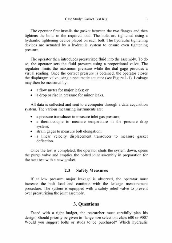
The operator then introduces pressurized fluid into the assembly. To do so, the operator sets the fluid pressure using a proportional valve. The regulator limits the maximum pressure while the dial gage provides a visual reading. Once the correct pressure is obtained, the operator closes the diaphragm valve using a pneumatic actuator (see Figure 1-1). Leakage may then be measured by:
• a flow meter for major leaks; or • a drop or rise in pressure for minor leaks.
All data is collected and sent to a computer through a data acquisition
system. The various measuring instruments are:
• a pressure transducer to measure inlet gas pressure; • a thermocouple to measure temperature in the pressure drop
system; • strain gages to measure bolt elongation; • a linear velocity displacement transducer to measure gasket
deflection.
Once the test is completed, the operator shuts the system down, opens the purge valve and empties the bolted joint assembly in preparation for the next test with a new gasket.
2.3 Safety Measures
If at low pressure major leakage is observed, the operator must increase the bolt load and continue with the leakage measurement procedure. The system is equipped with a safety relief valve to prevent over pressurizing the joint assembly.
3. Questions
Faced with a tight budget, the researcher must carefully plan his design. Should priority be given to flange size selection: class 600 or 900? Would you suggest bolts or studs to be purchased? Which hydraulic

Chapter One
4
components should be used? Which control system should be selected to adjust the proportional valve? Have all safety measures been implemented to prevent incidents and accidents with or without material losses and injuries?
The main objective of this test is to measure leakage from the gasket being tested. All other rig components must be leak proof. Which design strategies must the researcher prioritize to ensure this? How will the researcher measure leaks from the gasketed joint?
The test rig will be used for teaching purposes. Therefore, the researcher would like the work station to be ergonomic and safe. He fears it may be used improperly. He must take into account safety margin requirements when designing the rig and must comply with machine safety standards and the applicable pressure vessel code.
The solution that will be chosen will undergo further study in the following aspects:
3.1 Strength of Materials
Refer to the conditions of usage provided in sections I Problem and II Facts to review the problem specifications.
Suppose a 4-inch diameter flange joint. • Verify the mechanical integrity of the test rig structural
components, namely the flange (material, thickness, class or grade), bolts (material, quantity and length), tank (material, thickness, dimensions).
• Specify the maximum bolt load capacity knowing that cyclic loading will be conducted on the gasket, without exceeding a maximum gasket stress of 23,000 psi.
3.2 Hydraulic and Pneumatic Systems
Refer to the conditions of usage described in sections I Problem and II Facts to review the problem specifications.
Select each of the hydraulic and pneumatic components for the test rig (tubes, valves, connections, and hydraulic and pneumatic devices).

Case Study: Gasket Test Rig
5
You are asked to design a hydraulic system and select hydraulic tightening devices to tighten the bolts (pump, tank, channels, oil, etc.).
Also, the bench test rig manufacturing costs are to be kept to a minimum. You are asked to propose a system to control the proportional valve (setting, feedback and actuator). The hydraulic system maximum pressure should be established in accordance to the operating conditions of the test rig.
3.3 Ergonomics and Occupational Safety
Verify that the test rig complies with the act respecting occupational health and safety and the regulation on occupational health and safety.
Consult machine safety standards and propose safety measures to prevent risks during operation.
Acknowledgements
The authors would like to thank École de technologies supérieure for its financial support. They also wish to acknowledge the collaboration of Daniel Mongrain, Jean-Claude Bergeron and Hichem Beghoul in collecting information.
References
Department of Defense, Design Criteria Standard Human Engineering, MIL-STD-1472F, États-Unis. [Internet]. Available from: www.hf.faa.gov/docs/milstd14.pdf.
Labonville, R. Concepts des circuits hydrauliques : une approche énergétique. Éditions de l’École Polytechnique de Montréal, 1991.
Lupin, H. et Marsot, J. Sécurité des machines et des équipements de travail. Moyens de protection contre les risques mécaniques. Édition INRS ED 807, France, 2000.
Merritt, H.E. Hydraulic Control Systems. John Willey & Sons, New York, 1993.
Rabardel, P., Carlin, N., Chesnais, M., Lang, N., Le Joliff, G. et Pascal, M. Ergonomie concepts et méthodes. Éditions Octares, France, 1998.
Regulation on occupational health and safety. Gazette officielle du Québec. Décret 885-2001.
Chapter One
6
Sullivan, J.A. Fluid Power System: Theory and Applications. 3rd edition, Englewood Cliffs, New Jersey, 1989.
The Act Respecting Occupational Health and Safety, R.S.Q., Chapter S-2.1.
Figure 1-1: Pressurization and leakage detection system
CHAPTER TWO
CASE STUDY: DESIGNING A LOG SPLITTER
H. A. BOUZID, J.-P. KENNÉ, S. NADEAU, T. GOWINGS
Summary
This case study will focus on designing equipment used to prepare firewood. The case study format is used to enable engineering students to work on multidisciplinary projects. The purpose of this case is to combine knowledge in human factors engineering, fluid power systems and strength of materials to design a log splitter. Students will use material learned from each of these fields to solve the problems presented in this case study. Results obtained from this study will enable professors to carry out further projects or case studies. Keywords: Human factors engineering, fluid power systems, strength of materials, log splitter
1. Key Considerations and Objectives
Any fireplace, woodstove or wood furnace owner must eventually stock up on firewood, and this implies chopping wood to the right size for use. A splitting maul and chainsaw are obvious tools at one’s disposal. However, partisans of ready-made products will prefer to simply purchase a cord of firewood. Regardless of how one goes about it, one thing is certain, to get from a log to firewood, one must, among other things, split wood.
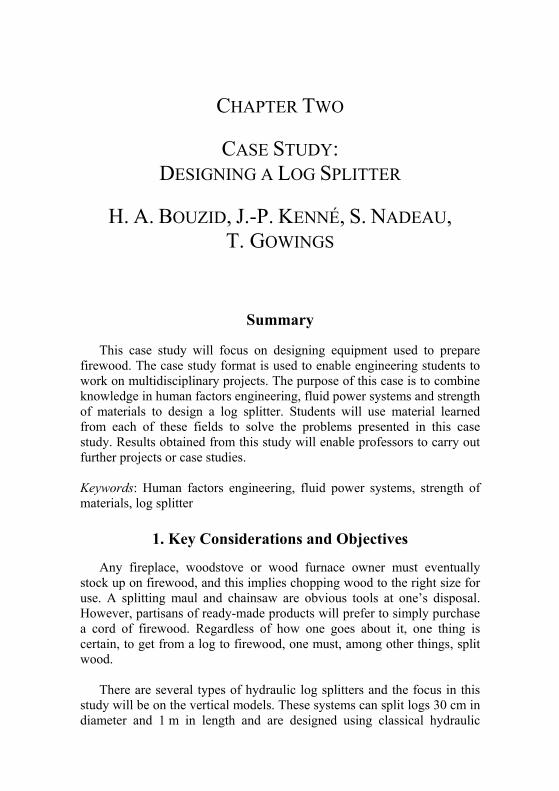
There are several types of hydraulic log splitters and the focus in this study will be on the vertical models. These systems can split logs 30 cm in diameter and 1 m in length and are designed using classical hydraulic
Chapter Two
8
principles, J.A Sullivan (1989), R. Labonville (1991) and H.E. Merritt (1993). Dimensions and choice of components must comply with current standards (Rabardel et al. 1998). Equipment must also comply with the act respecting occupational health and safety and be ergonomic.
In this case study, we will review the design of commonly used firewood splitters (see Figures 2-1 and 2-2). Our specific objectives are to:
• Conduct a conceptual study of the system and establish the dimensions of each of the components and structures used;
• Analyze and design a work station in accordance with occupational health and safety standards;
• Analyze and design a hydraulic system by assembling hydraulic power components.
2. Facts
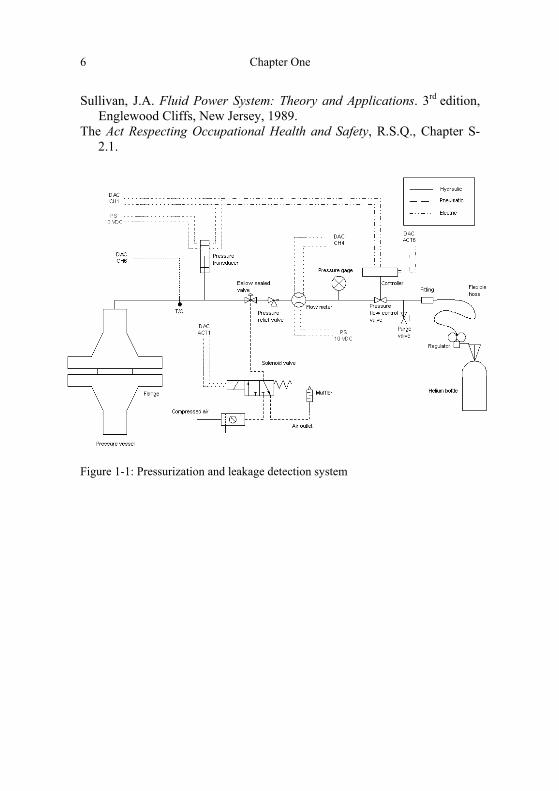
2.1 Characteristics of a Log Splitter A log splitter can operate at ambient temperatures varying between
minus 25°C and 35°C and must be corrosion proof. The hydraulic and electric components are equipped with appropriate gasket joints. Log splitters must sometimes be carried to quite remote locations in the forests of Quebec and are usually kept in cramped spaces (1 m by 1 m by 1½ m). More often than not, the ground on which they are set is hilly, so the equipment structure must be robust and able to maintain secure footing to ensure stability when in use.
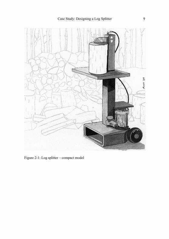
Case Study: Designing a Log Splitter 9
Figure 2-1: Log splitter – compact model
Chapter Two
10
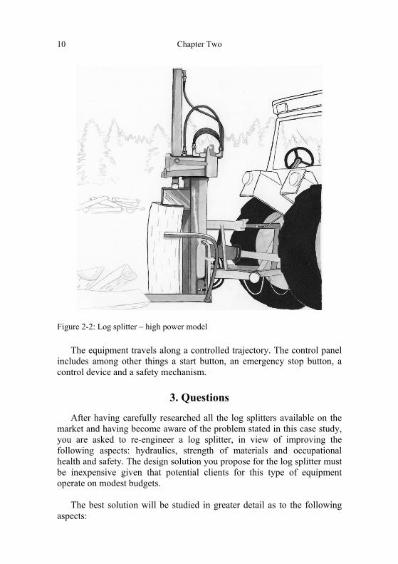
Figure 2-2: Log splitter – high power model
The equipment travels along a controlled trajectory. The control panel includes among other things a start button, an emergency stop button, a control device and a safety mechanism.
3. Questions
After having carefully researched all the log splitters available on the market and having become aware of the problem stated in this case study, you are asked to re-engineer a log splitter, in view of improving the following aspects: hydraulics, strength of materials and occupational health and safety. The design solution you propose for the log splitter must be inexpensive given that potential clients for this type of equipment operate on modest budgets.
The best solution will be studied in greater detail as to the following aspects:
Case Study: Designing a Log Splitter 11
3.1 Strength of Materials
You are asked to establish the dimensions of the log splitter of your choice and provide detailed calculations. You must design the base and main structure of the splitter and make all necessary structural calculations, select the primary hydraulic and electric components (motor, pump, cylinder and tank) and calculate the power requirement.
Once this has been completed, use a general purpose finite elements software to model the log splitter structure for the purpose of analyzing the strength of the structure under different operating conditions for example, the machine falls over on a hill, or off a truck during transportation.
In comparison with the two systems described above and the other types of splitters available on the market, suggest an alternative which you consider better, based on your own set of criteria.
3.2 Hydraulic and Pneumatic Control Systems
It is required to design a hydraulic system and select components taking into account the pressure loss in the hydraulic circuit and accessories. Study the dynamic aspects and estimate the time required to split a specific number of logs. Calculate the energy efficiency of the system and, if needed, optimize the resulting solution. Finally, simulate the hydraulic system using a software program of your choice.
3.3 Ergonomics and Occupational Safety
Make recommendations as to the ergonomics and safety of the splitter. More specifically:
• Using a causal tree, define 5 possible injuries. • Once the causal tree is completed, validate your observations by
referring to the articles from the regulation on occupational health and safety that are relevant to your design.
• Design the log splitter’s work table position to facilitate the worker’s task of manually loading the splitter.
• Design a control panel which takes into account the following indicators and actuators:
Chapter Two
12
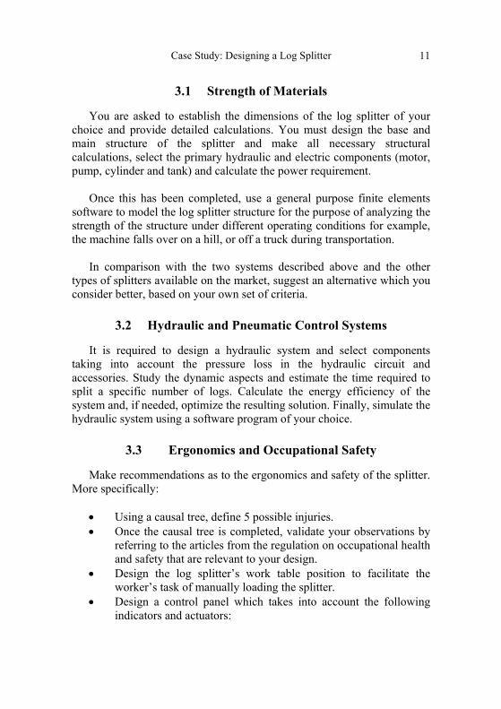
Table 2-1: Control panel component according to their level of importance
Component Level of
importance (1-10)
Light indicator during log splitter blade descent 9
Light indicator when log splitter is powered on 3
Light indicator to show status of blade safety breaks
6
Actuator for vertical displacement of blade (up / down)
7
Emergency stop button 10
Splitter start / stop pushbutton 4
Light indicator: small light. Actuator: Joystick, pushbutton, roller, lever, to choose from and justify your choice.
Determine the dimensions and type of indicator and justify your
choice. Position the actuators and determine their specifications (dimensions, colour, activation mode, etc.).
As an engineer working for a company owning a log splitter similar to
the one shown in figure 2-1, you are asked to investigate a reported accident, which has occurred while using this machine. Here is a summary of the event:
Mr. T was in a hurry to split a few logs because he had a busy day
ahead of him. It was the morning after a rainy night, and because the pile of wood was not properly covered, the logs were soaked. Mr. T knew that the log might slip, so he attempted to secure it with one hand while the other activated the “on” switch. His grip on the log was not strong enough, so the log slipped and flew violently out of place, hitting Mr. T on the head and twisting his wrist.
Do you think the product should be recalled by the company and
modified? What corrective solutions can you suggest to prevent this type of accident from occurring again? Note that for any modifications to the existing product, cost and facility of implementation are key factors.
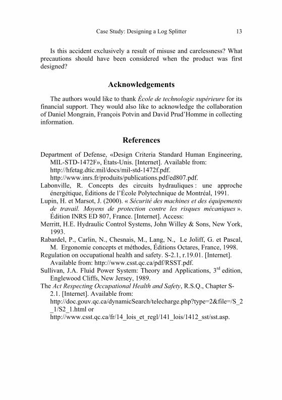
Case Study: Designing a Log Splitter 13
Is this accident exclusively a result of misuse and carelessness? What precautions should have been considered when the product was first designed?
Acknowledgements
The authors would like to thank École de technologie supérieure for its financial support. They would also like to acknowledge the collaboration of Daniel Mongrain, François Potvin and David Prud’Homme in collecting information.
References
Department of Defense, «Design Criteria Standard Human Engineering, MIL-STD-1472F», États-Unis. [Internet]. Available from: http://hfetag.dtic.mil/docs/mil-std-1472f.pdf.
http://www.inrs.fr/produits/publications.pdf/ed807.pdf. Labonville, R. Concepts des circuits hydrauliques : une approche
énergétique, Éditions de l’École Polytechnique de Montréal, 1991. Lupin, H. et Marsot, J. (2000). « Sécurité des machines et des équipements
de travail. Moyens de protection contre les risques mécaniques ». Édition INRS ED 807, France. [Internet]. Access:
Merritt, H.E. Hydraulic Control Systems, John Willey & Sons, New York, 1993.
Rabardel, P., Carlin, N., Chesnais, M., Lang, N., Le Joliff, G. et Pascal, M. Ergonomie concepts et méthodes, Éditions Octares, France, 1998.
Regulation on occupational health and safety. S-2.1, r.19.01. [Internet]. Available from: http://www.csst.qc.ca/pdf/RSST.pdf.
Sullivan, J.A. Fluid Power System: Theory and Applications, 3rd edition, Englewood Cliffs, New Jersey, 1989.
The Act Respecting Occupational Health and Safety, R.S.Q., Chapter S-2.1. [Internet]. Available from: http://doc.gouv.qc.ca/dynamicSearch/telecharge.php?type=2&file=/S_2_1/S2_1.html or http://www.csst.qc.ca/fr/14_lois_et_regl/141_lois/1412_sst/sst.asp.

CHAPTER THREE
CASE STUDY: JEWELS OF TASMANIA
B. ATEME-NGUEMA
Summary
Designing flexible manufacturing workshops, better known as flexible manufacturing cells, will be the focus of this case study. By using a case study format, problems relating to the design, management and installation of a manufacturing system will enable engineering and management students to work on multidisciplinary projects for which integration of knowledge from operations and production management, industrial engineering and occupational health and safety will be essential. Considering the interconnectedness of these fields is part of the approach used to solve problems presented in this case. As well, information gathered and the work hypotheses formulated will enable professors to prepare projects or case studies. Keywords: Manufacturing systems, industrial engineering, operations and production management and occupational, health and safety
1. Context
In Dover, on the Island of Tasmania, Australia, a company named Jewels of Tasmania manufactures nine types of golden wooden toys. Since the beginning of the last century, the colour “gold” has become time-honoured and can be obtained from high quality graphite mined in China, where the colour gold symbolizes excellence and royalty.
Case Study: Jewels of Tasmania 15
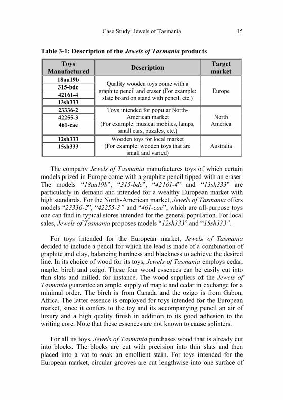
Table 3-1: Description of the Jewels of Tasmania products
Toys Manufactured Description Target
market 18au19b
Quality wooden toys come with a graphite pencil and eraser (For example:
slate board on stand with pencil, etc.) Europe 315-bdc
42161-4 13sh333 23336-2 Toys intended for popular North-
American market (For example: musical mobiles, lamps,
small cars, puzzles, etc.)
North America
42255-3 461-cae
12sh333 Wooden toys for local market (For example: wooden toys that are
small and varied) Australia 15sh333
The company Jewels of Tasmania manufactures toys of which certain
models prized in Europe come with a graphite pencil tipped with an eraser. The models “18au19b”, “315-bdc”, “42161-4” and “13sh333” are particularly in demand and intended for a wealthy European market with high standards. For the North-American market, Jewels of Tasmania offers models “23336-2”, “42255-3” and “461-cae”, which are all-purpose toys one can find in typical stores intended for the general population. For local sales, Jewels of Tasmania proposes models “12sh333” and “15sh333”.
For toys intended for the European market, Jewels of Tasmania decided to include a pencil for which the lead is made of a combination of graphite and clay, balancing hardness and blackness to achieve the desired line. In its choice of wood for its toys, Jewels of Tasmania employs cedar, maple, birch and ozigo. These four wood essences can be easily cut into thin slats and milled, for instance. The wood suppliers of the Jewels of Tasmania guarantee an ample supply of maple and cedar in exchange for a minimal order. The birch is from Canada and the ozigo is from Gabon, Africa. The latter essence is employed for toys intended for the European market, since it confers to the toy and its accompanying pencil an air of luxury and a high quality finish in addition to its good adhesion to the writing core. Note that these essences are not known to cause splinters.
For all its toys, Jewels of Tasmania purchases wood that is already cut into blocks. The blocks are cut with precision into thin slats and then placed into a vat to soak an emollient stain. For toys intended for the European market, circular grooves are cut lengthwise into one surface of

Chapter Three
16
the slats. Rods of graphite/clay are inserted into the grooves. Then glue is applied to the slat, a second grooved slat is aligned to the first and they are pressed together to encase the writing core. The glued slats are then cut into individual sticks and the ends are trimmed to the standard pencil length. The pencils for European toys are then polished, painted and set to dry. On one end of the pencil a ferrule is glued, clamped and fitted with an eraser held in place by embossing the ferrule. To finish, all the toys are packed and placed into cardboard boxes fitting 25 units. All these operations are automated.
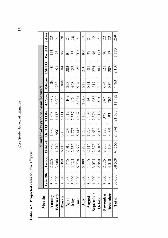
Jewels of Tasmania sells its products in cardboard boxes. For the next production lots, ecologists have expressed that industries manufacturing various wood products contribute to irresponsible over-logging by African foresters, particularly the ozigo species for which no effort is made to renew this resource. In light of this, Jewels of Tasmania wishes to take this into consideration and reduce, if possible, its production of luxury toys made with ozigo. The projected sales for the company are:
Cas
e St
udy:
Jew
els o
f Tas
man
ia
17
T
able
3-2
: Pro
ject
ed sa
les f
or th
e 1st
yea
r
Mon
ths
Num
ber
of to
ys to
be
man
ufac
ture
d
18
au19
b31
5-bd
c42
161-
4 13
sh33
323
336-
242
255-
346
1-ca
e12
sh33
315
sh33
3#
days
Ja
nuar
y 3
000
2 22
5 4
332
1 33
2 1
343
1 00
9 1
103
110
113
22
Febr
uary
3
000
3 40
0 1
210
996
1 11
5 2
080
783
151
55
21
Mar
ch
4 00
0 3
050
6 11
1 3
133
5 11
1 17
1
044
104
98
20
Apr
il 5
000
1 77
5 7
012
3 20
1 3
012
1 10
5 20
3 20
3 10
1 21
M
ay
5 00
0 4
125
2 33
7 1
773
2 33
7 45
2 40
8 12
2 75
20
Ju
ne
8 00
0 6
778
6 66
7 5
418
1 66
7 2
031
904
125
202
21
July
6
000
5 00
0 3
823
1 22
7 1
125
2 00
9 21
7 21
0 10
0 17
A
ugus
t 3
000
1 11
5 2
115
1 77
3 2
005
49
811
181
27
21
Sept
embe
r 4
000
3 07
5 2
373
1 65
7 2
376
1 08
2 24
7 27
4 96
22
O
ctob
er
3 00
0 2
850
4 01
6 2
098
1 01
6 91
9 50
3 30
1 17
3 21
N
ovem
ber
3 00
0 2
125
3 37
7 1
337
377
167
694
121
70
22
Dec
embe
r 3
000
3 01
0 4
193
3 99
6 19
3 70
2 85
2 20
7 83
22
T
otal
50
000
38
528
47
566
27
941
21
677
11
572
7
769
2 10
9 1
193
250
Cha
pter
Thr
ee
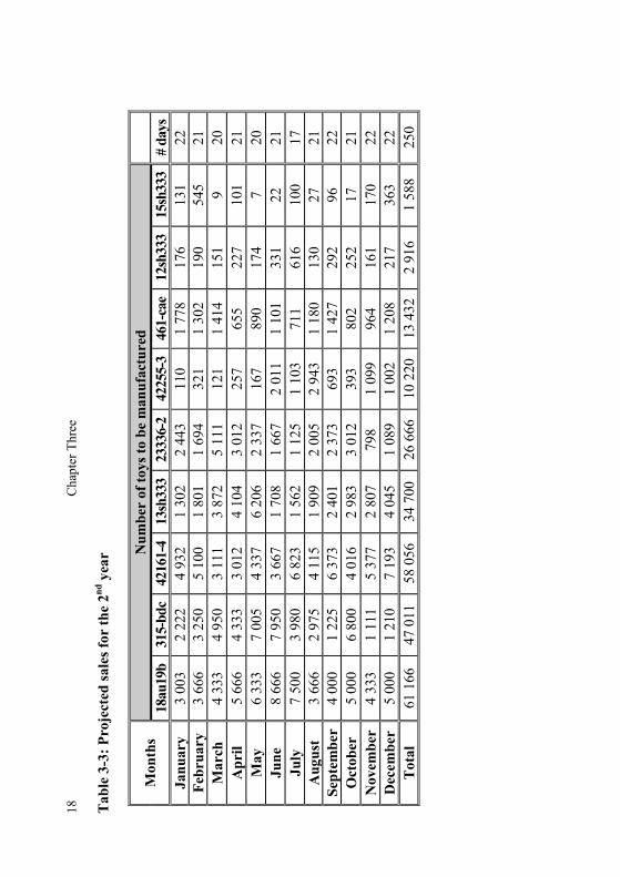
18 T
able
3-3
: Pro
ject
ed sa
les f
or th
e 2nd
yea
r
Mon
ths
Num
ber
of to
ys to
be
man
ufac
ture
d
18au
19b
315-
bdc
4216
1-4
13sh
333
2333
6-2
4225
5-3
461-
cae
12sh
333
15sh
333
# da
ys
Janu
ary
3 00
3 2
222
4 93
2 1
302
2 44
3 11
0 1
778
176
131
22
Febr
uary
3
666
3 25
0 5
100
1 80
1 1
694
321
1 30
2 19
0 54
5 21
M
arch
4
333
4 95
0 3
111
3 87
2 5
111
121
1 41
4 15
1 9
20
Apr
il 5
666
4 33
3 3
012
4 10
4 3
012
257
655
227
101
21
May
6
333
7 00
5 4
337
6 20
6 2
337
167
890
174
7 20
Ju
ne
8 66
6 7
950
3 66
7 1
708
1 66
7 2
011
1 10
1 33
1 22
21
Ju
ly
7 50
0 3
980
6 82
3 1
562
1 12
5 1
103
711
616
100
17
Aug
ust
3 66
6 2
975
4 11
5 1
909
2 00
5 2
943
1 18
0 13
0 27
21
Se
ptem
ber
4 00
0 1
225
6 37
3 2
401
2 37
3 69
3 1
427
292
96
22
Oct
ober
5
000
6 80
0 4
016
2 98
3 3
012
393
802
252
17
21
Nov
embe
r 4
333
1 11
1 5
377
2 80
7 79
8 1
099
964
161
170
22
Dec
embe
r 5
000
1 21
0 7
193
4 04
5 1
089
1 00
2 1
208
217
363
22
Tot
al
61 1
66
47 0
11
58 0
56
34 7
00
26 6
66
10 2
20
13 4
32
2 91
6 1
588
250


![mechaNICAL ENGINEERING [CAY 2019-20]](https://static.fdokumen.com/doc/165x107/6315d572c72bc2f2dd04da92/mechanical-engineering-cay-2019-20.jpg)