Improved design and screening of high bioactivity peptides for drug discovery
RESEARCH
ARTIC
LE
Copyright © 2012 American Scientific PublishersAll rights reservedPrinted in the United States of America
Journal ofNanoscience and Nanotechnology
Vol. 12, 1–10, 2012
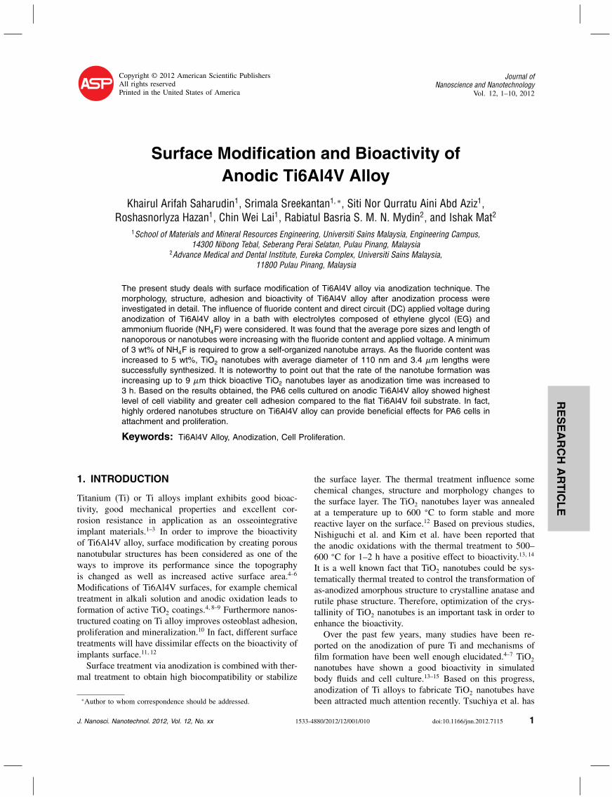
Surface Modification and Bioactivity ofAnodic Ti6Al4V Alloy
Khairul Arifah Saharudin1, Srimala Sreekantan1�∗, Siti Nor Qurratu Aini Abd Aziz1,Roshasnorlyza Hazan1, Chin Wei Lai1, Rabiatul Basria S. M. N. Mydin2, and Ishak Mat2
1School of Materials and Mineral Resources Engineering, Universiti Sains Malaysia, Engineering Campus,14300 Nibong Tebal, Seberang Perai Selatan, Pulau Pinang, Malaysia
2Advance Medical and Dental Institute, Eureka Complex, Universiti Sains Malaysia,11800 Pulau Pinang, Malaysia
The present study deals with surface modification of Ti6Al4V alloy via anodization technique. Themorphology, structure, adhesion and bioactivity of Ti6Al4V alloy after anodization process wereinvestigated in detail. The influence of fluoride content and direct circuit (DC) applied voltage duringanodization of Ti6Al4V alloy in a bath with electrolytes composed of ethylene glycol (EG) andammonium fluoride (NH4F) were considered. It was found that the average pore sizes and length ofnanoporous or nanotubes were increasing with the fluoride content and applied voltage. A minimumof 3 wt% of NH4F is required to grow a self-organized nanotube arrays. As the fluoride content wasincreased to 5 wt%, TiO2 nanotubes with average diameter of 110 nm and 3.4 �m lengths weresuccessfully synthesized. It is noteworthy to point out that the rate of the nanotube formation wasincreasing up to 9 �m thick bioactive TiO2 nanotubes layer as anodization time was increased to3 h. Based on the results obtained, the PA6 cells cultured on anodic Ti6Al4V alloy showed highestlevel of cell viability and greater cell adhesion compared to the flat Ti6Al4V foil substrate. In fact,highly ordered nanotubes structure on Ti6Al4V alloy can provide beneficial effects for PA6 cells inattachment and proliferation.
Keywords: Ti6Al4V Alloy, Anodization, Cell Proliferation.
1. INTRODUCTION
Titanium (Ti) or Ti alloys implant exhibits good bioac-tivity, good mechanical properties and excellent cor-rosion resistance in application as an osseointegrativeimplant materials.1–3 In order to improve the bioactivityof Ti6Al4V alloy, surface modification by creating porousnanotubular structures has been considered as one of theways to improve its performance since the topographyis changed as well as increased active surface area.4–6
Modifications of Ti6Al4V surfaces, for example chemicaltreatment in alkali solution and anodic oxidation leads toformation of active TiO2 coatings.
4�8–9 Furthermore nanos-tructured coating on Ti alloy improves osteoblast adhesion,proliferation and mineralization.10 In fact, different surfacetreatments will have dissimilar effects on the bioactivity ofimplants surface.11�12
Surface treatment via anodization is combined with ther-mal treatment to obtain high biocompatibility or stabilize
∗Author to whom correspondence should be addressed.
the surface layer. The thermal treatment influence somechemical changes, structure and morphology changes tothe surface layer. The TiO2 nanotubes layer was annealedat a temperature up to 600 �C to form stable and morereactive layer on the surface.12 Based on previous studies,Nishiguchi et al. and Kim et al. have been reported thatthe anodic oxidations with the thermal treatment to 500–600 �C for 1–2 h have a positive effect to bioactivity.13�14
It is a well known fact that TiO2 nanotubes could be sys-tematically thermal treated to control the transformation ofas-anodized amorphous structure to crystalline anatase andrutile phase structure. Therefore, optimization of the crys-tallinity of TiO2 nanotubes is an important task in order toenhance the bioactivity.Over the past few years, many studies have been re-
ported on the anodization of pure Ti and mechanisms offilm formation have been well enough elucidated.4–7 TiO2
nanotubes have shown a good bioactivity in simulatedbody fluids and cell culture.13–15 Based on this progress,anodization of Ti alloys to fabricate TiO2 nanotubes havebeen attracted much attention recently. Tsuchiya et al. has
J. Nanosci. Nanotechnol. 2012, Vol. 12, No. xx 1533-4880/2012/12/001/010 doi:10.1166/jnn.2012.7115 1

RESEARCH
ARTIC
LE
Surface Modification and Bioactivity of Anodic Ti6Al4V Alloy Saharudin et al.
been reported on the formation of nanostructured oxidefilms on TiAl and Ti–Ta alloys since 2007.16�17 Later,Saji et al. has been discussed the formation of nanotubularoxide layers on Ti–35Nb–5Ta–7Zr alloy in 2009.18 In fact,an earlier report by Ghicov et al. regarding to the anodiza-tion of Ti45Nb alloy to grow Ti–Nb–O nanotubes, whichshow enhanced thermal stability in comparison with thatof TiO2 nanotubes on pure Ti.19 In addition, Aucklandet al. has been claimed that development of nanostructuredoxide films on Ti–Nb and Ti–Ta that has lower surfaceresistance and improved chemical stability than pure Tifor proton exchange membrane (PEM) fuel cells.20 Con-sidering the great advantages (better corrosion resistance,higher wear resistance and enhanced tissue response) ofTi6Al4V alloy for clinical applications,10�21 oxide nano-tubes grown on Ti6Al4V alloys are expected to have abright future.The effects of surface topography on cell adhesion have
been extensively studied over the last decade, but no con-sensus has been reached. Several authors have reportedan association between increased implant surface rough-ness (as a result of specific texturization techniques) andimproved cell adhesion and proliferation findings.16�22–24
However, many studies have been proved that this tech-nique increased the surface roughness and it was not adeterminant factor for initial cell response.25–26 Finally, anin vitro study has suggested that osteoblasts show a pref-erence for surfaces with a high degree of microrough-ness (mean roughness of approximately 0.5 �m).28 In thepresent study, developments of self organized nanotubearrays on Ti6Al4V alloy with optimize fluoride content,applied voltage and anodization time were investigated.The ultimate aim of the study was optimized the nanotubelayer thickness, morphology and crystal structure to assessthe proliferation of PA6 mouse bone marrow stromal cellcultured on these surfaces. The assessment was carried outusing quantitative analysis of cell proliferation.
2. EXPERIMENTAL PROCEDURE
2.1. TiO2 Nanotubes Formation
Ti6Al4V alloys supplied by Straits Orthopaedics (Mfg)Sdn. Bhd. were used as substrates for the anodic growthof TiO2 nanotube layers. The alloy samples with a sizeof 0�5 × 0�5 × 5 cm3 were ultrasonically cleaned for30 minutes in a mixture solution of 1 M HNO3 and0.45 M NH4F. After cleaning, the samples were rinsedwith deionized water and air dried. For anodization anelectrochemical cell with 2 electrode configuration wasused. Platinum electrode served as cathode and Ti6Al4Vserved as anode. Electrochemical experiments were car-ried out using a Keithley 2611 A system sourcemeter. Theanodization has been made at different fluoride amount of1, 3, 4 and 5 wt% of NH4F and direct current voltage var-ied from 10 to 60 V. Nanotubes formation was achieved
at potential 60 V and time ranging from 20 secondsto 6 hour. After anodization the samples were ultrasoni-cally cleaned in acetone for 1 minute, rinsed with deion-ized water and dried in nitrogen stream. The as-anodizedsamples were heat treated by annealing at temperatureranging from 400 to 600 �C. For morphological char-acterization of samples, field emission scanning electronmicroscope (FESEM-Zeiss, Supra 35VP) was used and thecrystal structure of the TiO2 nanotubes was studied byX-ray diffraction (Phillip model PW 1729). The surfaceroughness of TiO2 nanotubes samples were characterizedusing SPA 300 HV Scanning Probe Microscope.
2.2. PAC (Bone Marrow Stromal Cell Lines) Culture
Two samples; Ti6Al4V alloy and TiO2 nanotubes formedon Ti6Al4V alloy were cut into 5× 3 mm in dimen-sion. TiO2 nanotubes samples were annealed at 400 �C toobtain anatase phase. Each of samples was placed in sep-arate bottle. The samples were then autoclaved at 120 �Cfor 20 minutes. All the samples were put in the 96 wellplates. 200 �l �-MEM Gibco medium (10% Fetal BovineSerum (Gibco)+1% Penicilin Steptomicin+Gentamicin+Amphoterin) was put in each well. The cells are seeded atconcentration of 1×10⁵ cells/well. The prepared sampleswere then incubated for 1, 3 and 7 days in 5% CO2+95%air at 37 �C. Then the cell morphology was observed andthe viable attached cells counted as a function of incuba-tion time.
2.3. MTS Proliferation Assay
The density of viable cells was estimated. MTS assays(promega) are colorimetric assays for measuring the activ-ity of enzymes that close dyed to formazan dyes, givinga purple color. After the selected incubation periods, thesamples were washed 3 times by PBS and transferred toa new 96-well polystyrene culture plate. A 40 �l quan-tity of MTS dye agent added to each well followed by200 �l complete �-MEM Gibco medium. After 3 hour ofincubation in a 5% CO2 incubator, all media were put ineach well of 96-well polystyrene culture plate. Finally theabsorbance of each solution was measured at a wavelengthof 490 nm by ELISA plate reader.
3. RESULTS AND DISCUSSION
3.1. Effect of NH4F Content
The variations on surface morphology of the anodicTi6Al4V alloy with different NH4F concentrations dur-ing the anodization at 60 V for 1 hour are presented inFigures 1(a)–(d). Anodization of Ti6Al4V alloy in elec-trolyte containing 1 wt% of NH4F formed an irregularnanoporous structure with 2.3 �m (Fig. 1(a)) on the sur-face Ti6Al4V alloy. It could be observed that parts of
2 J. Nanosci. Nanotechnol. 12, 1–10, 2012

RESEARCH
ARTIC
LE
Saharudin et al. Surface Modification and Bioactivity of Anodic Ti6Al4V Alloy
Fig. 1. FESEM images of Ti6Al4V alloys anodized in EG+1–5 wt% NH4F at 60 V for 1 hour. (a) 1 wt%, (b) 3 wt%, (c) 4 wt%, (d) 5 wt%.
the anodic oxide layer were covered with small pits andlarger pores. The reason mainly attributed to the differentin the degree of localized dissolution of the oxide layer.Figure 1(b) shows the Ti6Al4V alloys anodized in EG con-taining 3 wt% NH4F. It was noticed that pits and poreshave been started to convert into sponge like structure.The inset shows the thickness of sponge like structures ofabout 2.3 �m. Besides, it could also be noticed that theentire Ti6Al4V alloy surface was not uniformly coveredwith nanoporous structure.For 4 wt% and 5 wt% NH4F, self organized TiO2 nano-
tubes array was formed (Figs. 1(c) and (d)). The averagediameter of the nanotubes is approximately 81 and 110 nmfor 4 wt% and for 5 wt%, respectively, while the nanotubeslength is 3.4 �m for both samples. Generally, the pores orthe nanotube diameter are found to be larger with increas-ing fluoride content in the electrolyte. It is worth to notethat the growth of TiO2 nanotubes depends on the oxidegrowth rate and the chemical dissolution of the oxide byfluoride ion. Excess fluoride ion increases the electricalfield intensity at the bottom of the pore thus drives fur-ther oxidation, and field assisted dissolution where Ti ionscome out of the metal and dissolve in solution. This indi-cates that the chemical dissolution of anodic oxide later isinduced by fluoride ion.29–32
The corresponding XRD patterns of the Ti alloy sheet asa function of fluoride content are shown in Figure 2. Afterannealing at 400 �C, the diffraction peak appears at 2� of25� representing (101) plane of anatase TiO2. In addition,
diffraction pattern of �-Ti at 2� = 35�18�, 40.26�, 53.08�
and 63.19� corresponding to the (100), (101), (102), (110)plane and �-Ti peak at 38.75� corresponding at (002) planewere detected. These peaks are originated from the sub-strate of the Ti alloy. It is worth to note that the peakintensity of � and � Ti decreased as the content of fluo-ride increased. This is likely due to larger thickness of theoxide layer formed on the Ti6Al4V alloy.
Fig. 2. XRD pattern of Ti6Al4V alloys anodized in EG+ 1–5 wt%NH4F at 60 V for 1 hour and annealed at 400 �C for 4 hours in argonatmosphere. (a) 1 wt%, (b) 3 wt%, (c) 4 wt%, and (d) 5 wt% weight ofNH4F. A= Anatase, �-Ti= alpha Ti and �-Ti= Beta Ti.
J. Nanosci. Nanotechnol. 12, 1–10, 2012 3

RESEARCH
ARTIC
LE
Surface Modification and Bioactivity of Anodic Ti6Al4V Alloy Saharudin et al.
Fig. 3. FESEM images of Ti6Al4V alloys anodized in EG+5 wt% NH4F at voltage varied from 10–40 V for 1 hour.
3.2. Effect of DC Applied Voltage
The influence of DC applied voltage on the morphologyof oxide layers prepared by anodization of Ti alloys inan electrolyte bath composed of EG and 5 wt% of NH4Fas exhibited in Figure 3. The effect of applied voltagewas observed in the range of 10–60 V. At 10 V, smallpits are observed on the surface of the oxide layer. Atthis stage the dissolution of Ti had just occurred. As thevoltage increased to 20 V, the pits nucleate to form largeporous structure. However, not all the surface is coveredwith porous TiO2. There are still areas covered with com-pact oxide layer. This is due to the insufficient voltageto induce complete dissolution and breakdown of barrierlayers to dissolve the oxide into tubes.21�33
When applied voltage was increased to 30 V up to60 V, self organized nanotube arrays are formed. Howeverthe lengths of the nanotubes in certain area are relativelylow as compared to others. This finding is different com-pared to few authors who claimed the existence of twokinds of the nanostructure on the surface of the Ti6Al4Valloy. One was self organized nanotube arrays and theother was irregular nanoporous structure. According to fewauthors,34�22 the self organized nanotubes arrays are provento be grown on the � phase region and nanoporous struc-ture on � phase region. The � phase are enriched withAl whereas � phase region enriched with V. Because ofthe different chemistries of these phases, the formation ofthe nanotubular oxide layer is not uniform as � phases get
etched preferentially by the electrolyte. Different resultswere obtained in this work probably due to different elec-trolyte used. Most of the aforementioned studies utilizeaqueous solution which subjected high chemical dissolu-tion rate. In here the use of EG with pH 6.5 could avoid thesignificant attack on � phase and produce homogeneousmicrostructure. However, the length of the nanotubes aredifferent within the � and � phase region, being short at� phase region as the solubility of V is faster than the Al.
3.3. Effect of Anodization Time
Figure 4 shows the different surfaces that were obtainedby anodizing the Ti6Al4V alloy for varying durations at60 V in EG electrolyte containing 5 wt% NH4F. In the earlystage of anodization (20 seconds), compact oxide layers areformed on the surface of the of Ti6Al4V alloy due to theinteraction within O2− and OH−. After 1 minute the oxidelayer has been etched in certain area, thus forming irreg-ular pits due to localized dissolution. After 5 minutes ofanodization, the pits are converted to larger pores with mostof the areas are still covered with oxide layer. At 10 min-utes, a breakdown of the compact TiO2 layer occurredon the surface, after which a porous TiO2 layer gradu-ally grow and the TiO2 nanotubes with average lengthof 4 �m was obtained. After 15 minutes, the surface iscompletely filled with self organized nanotubes arrays. For30 minutes, the morphology become stable and graduallygrows up to 9 �m after 6 hour anodization. The overall
4 J. Nanosci. Nanotechnol. 12, 1–10, 2012

RESEARCH
ARTIC
LE
Saharudin et al. Surface Modification and Bioactivity of Anodic Ti6Al4V Alloy
Fig. 4. FESEM images of TiO2 nanotubes formed at 60 V in EG+5 wt% NH4F at various anodization time.
formation of the nanotubes on Ti6Al4V alloy is similarto the Ti–8Mn reported by Mohapatra et al.35 The diame-ter and length of TiO2 nanotubes formed are presented inTable I.The graph in Figure 5 shows the current density as a
function of anodization time. Such plot is important toexplain the mechanism of TiO2 nanotube formation. In theinitial stage of anodization (noted as region I), an abruptdecrease of current was observed due to the formation ofcompact oxide film. According to Zhao et al.36 this initial
Table I. Diameter and length of TiO2 nanotubes formed at variousanodization time.
Time Tube diameter Tube(minutes) (nm) length (�m) Morphology
20 sec – – Compact structure1 – 0.5 Pits formation5 64 2.4 Porous structure10 70 4.0 Nanotubes15 75 4.0 Nanotubes30 100 2.8 Nanotubes1 hour 110 3.4 Nanotubes3 hour 110 9.0 Nanotubes6 hours 150 9.0 Nanotubes
stage is known as passivation process of Ti as illustratedby Eq. (1).
Ti4++2H2O→ TiO2+4H+ (1)
In second stage (noted as region II) occur due to the pro-nounced dissolution at the pore bottoms that takes place
Fig. 5. Current time plot of Ti6Al4V anodization at 60 V in EG+5 wt% NH4F.
J. Nanosci. Nanotechnol. 12, 1–10, 2012 5

RESEARCH
ARTIC
LE
Surface Modification and Bioactivity of Anodic Ti6Al4V Alloy Saharudin et al.
Fig. 6. XPS high-resolution spectrum of the anodic Ti6Al4V alloy surface: (a) Ti 2p, (b) O 1s, (c) C 1s, (d) Al 2p and (e) V 2p.
which makes them significantly deeper. This chemical dis-solution reduces the thickness of the oxide barrier layerat the bottom of the pits and allows the electrochemicaletching process to continue. The oxide layer at the bottomof the pits is relatively thin; and the thin layer, in turn,increases the electric field intensity, resulting in furtherpore growth.In third stage (noted as region III), a constant equi-
librium is maintained with the increasing anodizing timewhile current density is slightly reduced due to the changesof the pores depth of pits. The thickness increases until asteady-state situation is established.
3.4. Chemical Composition
The chemical composition present at the surface ofTi6Al4V nanotube subjected to annealing at 400 �C for4 hours under Argon atmosphere was investigate using
Fig. 7. XRD patterns of TiO2 nanotubes formed at 60 V in EG+5 wt%NH4F for 1 hour. (a) As-anodized, and annealed at (b) 400 �C, (c) 500 �C,(d) 600 �C.
6 J. Nanosci. Nanotechnol. 12, 1–10, 2012

RESEARCH
ARTIC
LE
Saharudin et al. Surface Modification and Bioactivity of Anodic Ti6Al4V Alloy
XPS analysis, and the result is shown in Figure 6. Basedon the result, the binding energies of Ti2p3/2 and Ti2p1/2were found at 456.5 eV and 463.3 eV, respectively. Thisis likely due to the presence of Ti4+ oxidation state.37�38
The Ti4+ ions reacted with O2− ions during anodization,and consequently formed TiO2. This was confirmed by thepresence of Ti O (527.5–527.7 eV) in O1s. Besides, thepresence of OH− ions and absorbed H2O was detected at
Fig. 8. FESEM images and schematic diagram of TiO2 nanotube wall thickening of (a) as-anodized, and annealed at (b) 400 �C, (c) 500 �C, (d) 600 �C.
528.9 eV and 531.9 eV. The C 1s spectra for TiO2 madein ethylene glycol and glycerol were similar and revealedtwo peaks at 283.5 and 285.4 eV as well as an additionalshoulder at 286.5 eV (Fig. 6(b)). The strong peak posi-tioned at 283.5 eV is usually assigned to adventitious ele-mental carbon, which cannot be eliminated. This peak alsoexisted in the case of the pure TiO2 sample39�40 and it wasclose to the position of graphitic sp2-hybridized carbon
J. Nanosci. Nanotechnol. 12, 1–10, 2012 7

RESEARCH
ARTIC
LE
Surface Modification and Bioactivity of Anodic Ti6Al4V Alloy Saharudin et al.
(284.9 eV).37 The peak at 285.4 eV could be ascribed toTi C O bonds that comprise the carbonate species. Thishappens when C atoms are incorporated into the intersti-tial positions of the TiO2 lattice41�42 during pyrogenationof the organic compound.43
Other than the information of TiO2, binding energy ofAl2p was traced at 72.1 eV, 72.2 eV and 73.9 eV. This isattributed to the binding energy of Al–O, which in agree-ment with that report by Li et al. 2009.43 In addition, theV2p3/2 peak corresponding to the metallic V appears at515.5 eV and 518.2 eV. This is due to the fact that theaffinity of Al and Ti with O is stronger than that of V.Al and Ti diffused outward, bringing on implanted layeroutward growing, therefore V is deficient relatively in theoutmost layer. However, the existing of oxidized state ofAl, and the leaching of V contribute to reduce cellulartoxicity of Al and V of Ti6Al4V as biomaterial.43
3.5. Crystal Structure of TiO2 Nanotubes
Figure 7 shows the XRD pattern of the as-anodizedand annealed TiO2 nanotubes at different temperatures.Annealing is one of the most widely used post-fabricationprocedures which increases crystallinity of as-producedamorphous TiO2 nanotubes and removes surface fluorineto improve cell responses.44 This result clearly showsthat crystallization to the anatase structure occurs atlow temperature (400 �C). This is the same finding asAsk et al. where they successfully induced crystalliza-tion to the anatase structure at temperatures in the range300–400 �C.45 Annealing at 400 �C has promoted thecrystallization of anatase phase at 2� of 25� and 48�,corresponding to (101) and (200) plane, respectively.At 500 �C, rutile peak (110) at 27.8� starts to exist. Theweight fraction of anatase and rutile was 40% and 60%respectively. By increasing the temperature to 600 �C,the rutile peak with higher intensity is obtained, indicat-ing the presence of rutile with a high degree of crys-tallinity. The weight fraction of anatase and rutile was 9%and 91% respectively.The morphology schematic diagram of the as anodized
TiO2 nanotubes without heat treatment and annealedat 400 �C, 500 �C as well as 600 �C are shown inFigure 8. The morphology of the sample is significantlyaltered by the annealing process. Annealing at 400 �Censured that the nanotube structure will not be changed(Fig. 8(b)). At 500 �C (Fig. 8(c)), thickening of TiO2 nano-tubes wall occurred due to mass transport involving Ti4+
diffusion at the bottom and wall of the TiO2 nanotubes.Finally at 600 �C (Fig. 8(d)), tubular structure is com-pletely damaged and nanorod like structure is formed. Thechange in morphology with annealing temperature is per-haps associated with the excessive diffusion of Ti ion alongwith the nanotube walls, which induced oxidation and thusthickened the oxide walls.
Fig. 9. MTS assay data showing the cell viability (%) of reaction prod-uct of the MTS working solution with PA6 cells cultured after 1, 3,7 days of incubation. The error bars in the figure represent the standarddeviation for four samples for each data. Ti A (Ti6Al4V alloy substrate),TNT A (TiO2 nanotubes on Ti6Al4V alloy), Cont. (Control media).
3.6. Cell Attachment and Proliferation
To evaluate the viability of PA6 cells cultured on Ti6Al4Valloy, the MTS assays was employed in this study. After
Fig. 10. FESEM images of (a) flat Ti6Al4V alloy substrate and (b) TiO2
nanotubes layer on Ti6Al4V alloy.
8 J. Nanosci. Nanotechnol. 12, 1–10, 2012

RESEARCH
ARTIC
LE
Saharudin et al. Surface Modification and Bioactivity of Anodic Ti6Al4V Alloy
culturing for 1, 3 and 7 days, cell viability was quanti-fied. The pale-yellow MTS assays are converted to purpleformazon crystal only by the viable cells. Therefore theproduction of formazon indirectly reflects the viability ofcells. As shown in Figure 9, after 7 days of culture, PA6sgrown on anodized Ti6Al4V substrate showed statisticallyhigher (p < 0�001) cell viability than those grown on flatTi6Al4V alloy substrate. A similar trend was also foundafter 1 and 3 days of culture. It is well known those oste-blast cells are likely to attach on rough surface layer.46
Under FESEM (Fig. 10(a)) the Ti6Al4V alloy have roughcontour surface morphology while TiO2 nanotubes layergrowth on Ti6Al4V alloy (Fig. 10(b)) was uniform. Theadhesion of PA6 cell on day 7 was shown in Figure 11.Figure 11(a) shows that the PA6 cell on Ti6Al4V alloy sub-strate has filodopia like structure extending at the edge ofthe cell, while Figure 11(b) shows that almost every regionof TiO2 nanotubes surface have covered with PA6 cell.This result suggested that highly porous nanotubes struc-ture on Ti6Al4V alloy promote the growth of PA6 bonemarrow stromal cell lines consistently from day 1, 3 and 7while the rough surface of Ti alloy substrate might inducestress to the cells and eventually arrest the cells prolifer-ation cycle.47 This indicates that PA6 cells may responsedifferently to different surface structure. In addition, the
Fig. 11. FESEM images of PA6 bone marrow stromal cell cultured for7 days on (a) flat Ti6Al4V alloy substrate and (b) TiO2 nanotubes layeron Ti6Al4V alloy.
surface energy and surface roughness of nanotubes wouldbe essential factors for facilitating cells adhesion and pro-liferation.
4. CONCLUSION
In this study, well aligned TiO2 nanotube arrays onTi6Al4V alloy were successfully developed. Under opti-mized voltage and fluoride content, the nanotubes lengthranging from 1.6 �m to 9 �m were obtained after 6 hoursanodization. Thermal annealing does influenced the crys-tallinity of TiO2 nanotubes where transformation fromamorphous to rutile phase has successfully occur at tem-perature 600 �C. It is found that the PA6 bone marrowstromal cells preferred to attach on TiO2 nanotubes thanflat Ti6Al4V alloy. Cells cultured on nanotubes showedhighest level of viability and greater adhesion. Therefore,TiO2 nanotubes provided a favorable surface structure forcell attachment and growth.
Acknowledgment: The authors would like to thankUniversiti Sains Malaysia FRGS grant no. 6071213, andUSM Fellowship for sponsoring this work. The authorsgratefully acknowledge Straits Orthopaedics (Mfg) Sdn.Bhd. for providing the Ti6Al4V alloys.
References and Notes
1. M. Geetha, A. K. Singh, R. Asokamani, and A. K. Gogia, Prog.Mater. Sci. 54, 397 (2009).
2. P. Ducheyne and Q. Qiu, Biomaterials. 20, 2287 (1999).3. E. Jallot, Encyclopedia of Nanoscience and Nanotechnology, edited
by H. S. Nalwa, American Scientific Publishers, USA (2004), Vol. 7,p. 405.
4. S. Sreekantan, K. A. Saharudin, Z. Lockman, and T. W. Tzu, Nano-technology 21, 365603 (2010).
5. S. Sreekantan, C. W. Lai, and Z. Lockman, J. Electrochem. Soc.158, 397 (2011).
6. L. D. Sun, S. Zhang, X. W. Sun, and X. D. He, J. Nanosci. Nano-technol. 10, 4551 (2010).
7. Z. Lockman, S. Ismail, G. Kawamura, and A. Matsuda, Defect Dif-fus. Forum 312, 76 (2011).
8. H. Jha, R. Hahn, and P. Schmuki, Electrochim. Acta 55, 8883 (2010).9. A. Kaczmarek, T. Klekiel, and E. Krasicka-Cydzik, Surf. Interface
Anal. 42, 510 (2010).10. S. A. Catledge, M. Fries, and Y. K. Vohra, Encyclopedia of
Nanoscience and Nanotechnology, edited by H. S. Nalwa, AmericanScientific Publishers, USA (2004), Vol. 7, p. 741.
11. H. Lukavoca , B. Plesingerova, M. Vojtko, and G. Ban, Acta Metall.Slovac. 16, 186 (2010).
12. B. Plesingerova, H. Lukavoca, D. Horkavcova, and M. Vojtko, ActaMetall. Slovaca. 14, 356 (2008).
13. S. Nishiguchi, H. Kato, H. Fujita, M. Oka, H.-M. Kim, T. Kokubo,and T. Nakamura, Biomaterials 22, 2525 (2001).
14. H. M. Kim, F. Miyaji, T. Kokubo, and T. Nakamura, J. Biomed.Mater. Res. 32, 409 (1996).
15. K. Maekawa, Y. Yoshida, A. Mine, T. Fujisawa, B. V. Meerbeek,K. Suzuki, and T. Kuboki, J. Biomed. Mater. Res. A 82, 195 (2007).
16. H. Tsuchiya, S. Berger, J. M. Macak, A. Ghicov, and P. Schmuki,Electrochem. Commun. 9, 2397 (2007).
J. Nanosci. Nanotechnol. 12, 1–10, 2012 9

RESEARCH
ARTIC
LE
Surface Modification and Bioactivity of Anodic Ti6Al4V Alloy Saharudin et al.
17. H. Tsuchiya, T. Akaki, J. Nakata, D. Terada, N. Tsuji, Y. Koizumi,Y. Minamino, P. Schmuki, and S. Fujimoto, Corros. Sci. 51, 1528(2009).
18. V. S. Saji, H. C, Choe, and W. A. Brantley, Acta Biomater. 5, 2303(2009).
19. A. Ghicov, S. Aldabergenova, H. Tsuchyia, and P. Schmuki, Angew.Chem. Int. Ed. 45, 6993 (2006).
20. N. Aukland, A. Boudina, D. S. Eddy, J. V. Mantese, M. P. Thompson,and S. S. Wang, J. Mater. Res. 19, 1723 (2004).
21. E. Matykina, J. M. Hernandez-Lopez, A. C. C. Domingo, J. J. deDamborenea, and M. A. Arenas, Electrochim. Acta 56, 2221 (2011).
22. J. C. Keller, G. B. Schneider, C. M. Stanford, and B. Kellogg,Implant Dent. 12, 175 (2003).
23. L. Marinucci, S. Balloni, E. Becchetti, S. Belcastro, M. Guerra,M. Calvitti, C. Lilli, E. M. Calvi, and P. Locci, Int. J. Oral. Max-illofac. Implants. 21, 719 (2006).
24. S. Ozawa and S. Kasugai, Biomaterials 17, 23 (1996).25. M. Jayaraman, U. Meyer, M. Buhner, U. Joos, and H. P. Wiesmann,
Biomaterials 25, 625 (2004).26. S. Guizzardi, C. Galli, D. Martini, S. Belletti, A. Tinti, M. Raspanti,
P. Taddei, A. Ruggeri, and R. J. Scandroglio, Periodontol. 75, 273(2004).
27. B. Boyan, R. Batzer, K. Kieswetter, Y. Liu, D. L. Cochran, M. S.Szmuckler, D. D. Dean, and Z. Schwartz, J. Biomed. Mater. Res.29, 77 (1998).
28. K. Anselme, Biomaterials 21, 667 (2000).29. J. M. Macak., H. Hildebrand, U. Marten-Jahns, and P. Schmuki,
J. Electroanal. Chem. 621, 254 (2008).30. C. W. Lai, S. Sreekantan, and Z. Lockman, J. Nanosci. Nanotechnol.
12, 4057 (2012).31. S. Sreekantan, K. A. Saharudin, and C. W. Lai, IOP Conf. Ser.:
Mater. Sci. Eng. 21, 012002 (2011).
32. L. Su, Y. X. Gan, and J. G. Lawrence, Nanosci. Nanotechnol. Lett.4, 520 (2012).
33. C. W. Lai and S. Sreekantan, J. Nanomater. 2011, 142463(2011).
34. B. Luo, H. Yang, S. Liu, W. Fu, P. Sun, M. Yuan, Y. Zhang, andZ. Liu, Mater. Lett. 62, 4512 (2008).
35. S. K. Mohapatra, K. S. Raja, M. Misra, V. K. Mahajan, andM. Ahmadian, Electrochim. Acta 53, 590 (2007).
36. J. Zhao, X. I. Wang, R. Chen, and L. Li, Solid State Commun.134, 705 (2005).
37. L. Y. Zi, D. S. Hwang, N. H. Lee, and S. J. Kim, Chem. Phys. Lett.404, 25 (2005).
38. J. Xie and B. L. Luan, J. Mater. Res. 23, 768 (2008).39. X. Hu, T. Zhang, Z. Jin, J. Zhang, W. Xu, J. Yan, J. Zhang, L. Zhang,
and Y. Wu, Mater. Lett. 62, 4579 (2008).40. Y. Zhang, P. Xiao, X. Zhou, D. Liu, B. B. Garcia, and G. Cao,
J. Mater. Chem. 19, 948 (2009).41. W. J. Ren, Z. H. Ai, F. L. Jia, L. Z. Zhang, X. X. Fan, and Z. G.
Zou, Appl. Catal. B 69, 138 (2007).42. S. Sakthivel and H. Kisch, Angew. Chem. Int. Edn. 42, 4908
(2003).43. Y. Li, D. Y. Ding, C. Q. Ning, S. Bai, L. Huang, M. Li, and D. Mao,
Nanotechnology 20, 065708 (2009).44. K. M. Kummer, E. Taylor, and T. J. Webster, Nanosci. Nanotechnol.
Lett. 4, 483 (2012).45. M. Ask, U. Rolander, J. Lausmaa, and B. Kasemo, Mater. Res.
5, 1662 (1990).46. S. Oh, K. S. Brammer, K. S. Moon, J. M. Bae, and S. Jin, Mater.
Sci. Eng. C 31, 873 (2011).47. G. M. de Peppo, A. Palmquist, P. Borchardt, M. Lenneras, J. Hyllner,
A. Snis, J. Lausmaa, P. Thomsen, and C. Karlsson, Scientific WorldJournal 2012, 646417 (2012).
Received: xx Xxxx xxxx. Accepted: xx Xxxx xxxx.
10 J. Nanosci. Nanotechnol. 12, 1–10, 2012
Copyright © 2022 FDOKUMEN