Surface Failure and Durability of Induction-Hardened Sintered ...
8
A. Yoshida Professor. Okayama University, Department of Mechanical Engineering, Tsushima, Okayama 700, Japan Y. Ohue Research Associate. Okayama University, Department of Mechanical Engineering, Tsushima, Okayama 700, Japan I. Karasuno Chief Engineer. Sumitomo Metal Industries Ltd., Konohana-ku, Osaka 554, Japan Surface Failure and Durability of Induction-Hardened Sintered Powder Metal Rollers and Gears with Various Hardened Depths In this report, the effect of hardened depth on failure modes and fatigue strengths of induction-hardened sintered powder metal rollers and spur gears was elucidated, including the effect of relative radius of curvature of the rollers. These experimental results were discussed by an amplitude of ratio of orthogonal shear stress to Vickers hardness. Failure mode of the rollers was spoiling due to subsurface origin crack with slight micropits and that of the gears was pitting with spall near the pitch point independent of the hardened depth. The depths of spoiling cracks agreed almost with the occurring depths of peak amplitude of the ratio of orthogonal shear stress to Vickers hardness. Surface durability of the test rollers increased as the surface hardness increased and the relative radius of curvature decreased. Surface durability of the test rollers and the test gears was hardly influenced by the hardened depth. 1 Introduction In many cases sintered powder metal machine parts are em- ployed to reduce production cost. Surface-hardened sintered powder metal gears have also been employed as the power transmission gears in some recent motorcycles and other equip- ment. It is important to investigate the surface failure and the surface durability of the surface-hardened sintered powder metals in detail to evaluate the strength of sintered powder metal gears. Several interesting reports [1-7] on the fatigue failure, strength and surface durability of surface hardened melted steel gears have been published. However, investiga- tions [8-10] into surface-hardened sintered powder metal roll- ers or gears have been few and not sufficient for discussing the further application of surface-hardened sintered powder metals on power transmission gears. In order to discuss the effect of hardened depth on the failure mode and the surface durability of surface-hardened sintered powder metal gear, some studies were conducted using sintered powder metal rollers and spur gears treated by induction-hard- ening. Induction-hardened sintered powder metal rollers with three different hardened depths and two different diameters were fatigue-tested under a sliding-rolling contact condition. Induction-hardened sintered powder metal spur gears with three different hardened depths, which have a module of 5 and a standard pressure angle of 20 deg, were also fatigue tested using a power circulating gear testing machine. These exper- imental results on the failure mode and the fatigue strength were discussed using an amplitude of ratio and orthogonal shear stress to Vickers hardness, especially in terms of hardened depth and relative radius of curvature. 2 Test Rollers and Gears Shapes and dimensions of test rollers are shown in Fig. 1. Two kinds of rollers with diameters of 30 mm and 60 mm were employed in this experiment. Induction-hardened sintered powder metal rollers were used as test rollers having a shape of roller (1). Mating rollers having a shape of roller 2 were case-hardened chromium molybdenum steel (JIS: SCM415) rollers. Specifications of test spur gears are given in Table 1. Test gears with a module of 5 and a standard pressure angle of 20 deg were employed in this experiment. Induction-hard- ened sintered powder metal spur gears with 16 teeth were used as test gears. Case-hardened chromium molybdenum steel (JIS: SCM415) gears with 15 teeth were used as mating pinions. Table 2 gives the manufacturing conditions of induction- hardened sintered powder metal rollers and gears. The preal- loyed steel powder with particle diameters of 75 //.m to 106 ftrn was mixed with graphite and zinc stearate, and was compacted into discs. The green density of these discs was 6.9 g/cm . These discs were sintered, and then were machined to test rollers with diameters of 30 mm and 60 mm by turning and jo. f] S f pa pa Specimen mark IA30 IB30 1C30 CC30 IA60 I860 IC60 CC60 A 15 35 B 30 60 C 22 50 Contributed by the Power Transmission and Gearing Committee for publi- cation in the JOURNAL OF MECHANICAL DESIGN. Manuscript received Jan. 1992; revised Feb. 1994. Associate Technical Editor: D. G. Lewicki. Roller 1 Roller 2 Fig. 1 Shapes and dimensions of test rollers 730 / Vol. 116, SEPTEMBER 1994 Transactions of the ASME Copyright © 1994 by ASME Downloaded From: https://mechanicaldesign.asmedigitalcollection.asme.org on 06/19/2019 Terms of Use: http://www.asme.org/about-asme/terms-of-use
-
Upload
khangminh22 -
Category
Documents
-
view
2 -
download
0
Transcript of Surface Failure and Durability of Induction-Hardened Sintered ...

A. Yoshida Professor.
Okayama University, Department of Mechanical Engineering,
Tsushima, Okayama 700, Japan
Y. Ohue Research Associate. Okayama University,
Department of Mechanical Engineering, Tsushima, Okayama 700, Japan
I. Karasuno Chief Engineer.
Sumitomo Metal Industries Ltd., Konohana-ku, Osaka 554, Japan
Surface Failure and Durability of Induction-Hardened Sintered Powder Metal Rollers and Gears with Various Hardened Depths In this report, the effect of hardened depth on failure modes and fatigue strengths of induction-hardened sintered powder metal rollers and spur gears was elucidated, including the effect of relative radius of curvature of the rollers. These experimental results were discussed by an amplitude of ratio of orthogonal shear stress to Vickers hardness. Failure mode of the rollers was spoiling due to subsurface origin crack with slight micropits and that of the gears was pitting with spall near the pitch point independent of the hardened depth. The depths of spoiling cracks agreed almost with the occurring depths of peak amplitude of the ratio of orthogonal shear stress to Vickers hardness. Surface durability of the test rollers increased as the surface hardness increased and the relative radius of curvature decreased. Surface durability of the test rollers and the test gears was hardly influenced by the hardened depth.
1 Introduction In many cases sintered powder metal machine parts are em
ployed to reduce production cost. Surface-hardened sintered powder metal gears have also been employed as the power transmission gears in some recent motorcycles and other equipment. It is important to investigate the surface failure and the surface durability of the surface-hardened sintered powder metals in detail to evaluate the strength of sintered powder metal gears. Several interesting reports [1-7] on the fatigue failure, strength and surface durability of surface hardened melted steel gears have been published. However, investigations [8-10] into surface-hardened sintered powder metal rollers or gears have been few and not sufficient for discussing the further application of surface-hardened sintered powder metals on power transmission gears.
In order to discuss the effect of hardened depth on the failure mode and the surface durability of surface-hardened sintered powder metal gear, some studies were conducted using sintered powder metal rollers and spur gears treated by induction-hardening. Induction-hardened sintered powder metal rollers with three different hardened depths and two different diameters were fatigue-tested under a sliding-rolling contact condition. Induction-hardened sintered powder metal spur gears with three different hardened depths, which have a module of 5 and a standard pressure angle of 20 deg, were also fatigue tested using a power circulating gear testing machine. These experimental results on the failure mode and the fatigue strength were discussed using an amplitude of ratio and orthogonal shear stress to Vickers hardness, especially in terms of hardened depth and relative radius of curvature.
2 Test Rollers and Gears Shapes and dimensions of test rollers are shown in Fig. 1.
Two kinds of rollers with diameters of 30 mm and 60 mm were employed in this experiment. Induction-hardened sintered powder metal rollers were used as test rollers having a shape of roller (1). Mating rollers having a shape of roller 2 were case-hardened chromium molybdenum steel (JIS: SCM415) rollers. Specifications of test spur gears are given in Table 1. Test gears with a module of 5 and a standard pressure angle of 20 deg were employed in this experiment. Induction-hardened sintered powder metal spur gears with 16 teeth were used as test gears. Case-hardened chromium molybdenum steel (JIS: SCM415) gears with 15 teeth were used as mating pinions.
Table 2 gives the manufacturing conditions of induction-hardened sintered powder metal rollers and gears. The preal-loyed steel powder with particle diameters of 75 //.m to 106 ftrn was mixed with graphite and zinc stearate, and was compacted into discs. The green density of these discs was 6.9 g/cm . These discs were sintered, and then were machined to test rollers with diameters of 30 mm and 60 mm by turning and
jo.
f]
S f
pa pa
Specimen mark IA30 IB30 1C30 CC30 IA60 I860 IC60 CC60
A
15
35
B
30
60
C
22
50
Contributed by the Power Transmission and Gearing Committee for publication in the JOURNAL OF MECHANICAL DESIGN. Manuscript received Jan. 1992; revised Feb. 1994. Associate Technical Editor: D. G. Lewicki.
Roller 1 Roller 2
Fig. 1 Shapes and dimensions of test rollers
730 / Vol. 116, SEPTEMBER 1994 Transactions of the ASME
Copyright © 1994 by ASMEDownloaded From: https://mechanicaldesign.asmedigitalcollection.asme.org on 06/19/2019 Terms of Use: http://www.asme.org/about-asme/terms-of-use
to test gears by hobbing, respectively. The rollers and gearswere induction-hardened to have three different hardeneddepths respectively under the conditions given in Table 2. Circumferential surfaces of the test rollers and tooth surfaces ofthe test gears were finish-ground.
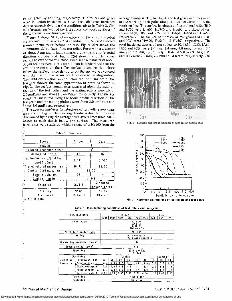
Figure 2 shows SEM observations on the circumferentialsurface and the cross section of an induction-hardened sinteredpowder metal roller before the test. Figure 2(a) shows thecircumferential surface of the test roller. Pores with a diameterof about 5 p,m and grinding marks along the circumferentialdirection are observed. Figure 2(b) shows the buffed crosssection below the roller surface. Pores with a diameter of about50 p,m are observed in this case. It can be understood that thesize of the pores on the roller surface is smaller than thosebelow the surface, since the pores on the surface are coveredwith the plastic flow at surface layer due to finish-grinding.The SEM observation on and below the tooth surface of thetest gear showed the same appearances of pores as shown inFig. 2. The surface roughnesses measured along the axial direction of the test rollers and the mating rollers were about2.0 p,mRmax and about 1.0 {tmRmax, respectively. The surfaceroughness measured along the tooth profile direction of thetest gears and the mating pinions were about 3.0 p,mRmax andabout 2.0 p,mRmax, respectively.
The average hardness distributions of test rollers and gearsare shown in Fig. 3. These average hardness distributions weredetermined by taking the average from several measured hardnesses at each depth below the surface. The measuredhardnesses were scattered within a range of ± HvlOO from the
average hardness. The hardnesses of test gears were measuredat the working pitch point along the normal direction to thetooth surface. The surface hardnesses of test rollers IA30, IB30and IC30 were Hv600, Hv740 and Hv690, and those of testrollers IA60, IB60 and IC60 were Hv630, Hv660 and Hv650,respectively. The surface hardnesses of test gears lAG, IBGand ICG were Hv590, Hv610 and Hv560, respectively. Thetotal hardened depths of test rollers IA30, IB30, IC30, IA60,IB60 and IC60 were 1.0 mm, 2.4 mm, 4.0 mm, 1.4 mm, 3.0mm and 5.2 mm, respectively. Those of test gears lAG, IBGand ICG wer'e 2.2 mm, 2.7 mm and 4.0 mm, respectively. The
Fig. 2 Surface and cross section of lest roller before lest
-IA30 -IA60----IB30 ----IB60---1C30 ---IC60..... --lAG-~-~ ··_·IBG~--\_-'-ICG
"'::-, "" '\ "",\ "h." \ \\ 1· .\\ \\.\ \
\ ,_ \o.._~_......--J
900 ~-----------,
800>:I:
700
~ 600c:
D
6 500.c:
Table 1 Gear data
~ 400-'>CU
;: 300
200
100
a~"----.L-.l-..L-Ji--J--l--l--'---J.---J.--J
a I ,0 2,0 3,0 4,0 5,0 5,0Depth below surface, Z ,11l11
* J IS B 1102 Fig. 3 Hardness distributions of test rollers and test gears
Items Pinion GearModule 5
Standard pressure angle 20'Number of teeth 15 16
Addendum modification0.511 0.560
coefficientTip circle diameter, mm 90. 11 94. 60
Center distance, mill 82. 55Pace width. 111m 18 6Contact ratio 1. 246
Material SCM415Sintered
Dowder metalGrinding Maag Nil esAccuracy* Class 1 Class 1
Table 2 Manufacturing conditions of test rollers and test gears
Specilen lark Roller GearIA30 I 1830 IC30 I IA60 IB60 IC60 lAG I IBG ICG
Powder type 0.7% Mn1. 0% Cr0.2% Mo
Balance FeParticle diaoeter, III 75-106
Mixing 0.5% Graphi te0.8% Zinc stearate
COIPacting pressur~ kN/cI' 64
Green densi ty, g/cI' 6. 9Sintering 1403X x 0.5hr
N, gasMachining Turning lIobbing
Induction- Freeuencv. kllz 30 30 30 30 30 30 30 30 30hardening Heatin. time. s 1.5 3.0 6.8 3. 7 6.0 14.0 6.0 7.1 8.0
Plate vol tage, kV 3. 5 6.0 4.8 6. 8 6. 8 5. 5 9. 5 8. 5 8. 5Plate current. A 1.5 3.0 2. 3 3. 5 3. 7 3.0 6. 2 5. 5 . 5. 5Grid current, A O. 13 O. 33 O. 30 O. 40 O. 35 O. 30 1. 10 1. 05 1. 05
TelDerln. 453X x 2hrFinishin. Grindin •.
Journal of Mechanical Design SEPTEMBER 1994, Vol. 116 J 731
Downloaded From: https://mechanicaldesign.asmedigitalcollection.asme.org on 06/19/2019 Terms of Use: http://www.asme.org/about-asme/terms-of-use

200
2 100
& 0
$ -100
" -ZOO
I -300
& -400
-500
-600
-700
-
i
-
(oz) r , z, mm ^
TO^—T^ | J — _ 4 ^ u _ i _
(oy)r ~ ' (o x ) r
IB30
IC30
( a x ) r : Ax ia l
( o y ) r : Circumferent ial
( d z ) r : Radial -700
IC60
( o x ) r : Axial
(tjy)r: Circuir
{ oz ) r : Radial
Fig. 4 Residual stress distributions of test rollers
Table 3 Property of lubricating oil
Specif ic gravity, Z88/277K Flash point, K Pour point, K
Kineaatic v i s cos i ty , x l O " s ' / s
313K 373K
Viscos i ty index Total acid nunber, HRKOH/R
0. 9022 477
260.5 190.9 17. 47 98
2.26
surface hardnesses of mating rollers were Hv840, and those of mating pinions were Hv800.
The residual stress distributions of the test rollers are shown in Fig. 4. The surface layer of the roller was removed by electrolytic polishing to measure the residual stress below the roller surface. The residual stresses were measured according to the 2d - sin2 i/< method using CrKa-ray as characteristic X-ray. Those stresses below the roller surface shown in Fig. 4 were obtained by modifying the measured residual stresses by means of the elastic calculation [11], since the measured stresses were influenced by the removal of the surface layer. The results indicate that the residual stresses in circumferential and axial directions of all test rollers were compressive near the surface layers. The residual stresses of test gears were not measured.
The Young's modulus and the Poisson's ratio of test rollers and test gears are 152 GPa and 0.25. The Young's modulus and the Poisson's ratio of mating rollers and mating pinions are 206 GPa and 0.30.
3 Experimental Procedures The rolling contact fatigue tests of the rollers were performed
under the combinations of the same diameter rollers using spring-loading type two cylinders testers [12], that are, nutcracker type testers. The relative radius of curvature in the pairs of 30 mm-diameter rollers was 7.5 mm, and that in the pairs of 60 mm-diameter rollers was 15 mm. The rotational speeds of 30 mm-diameter rollers were 3600 rpm for the faster roller and 2864 rpm for the slower roller, and those of 60 mm-diameter rollers were 1800 rpm for the faster roller and 1432 rpm for the slower roller. The circumferential velocities of these rollers were 5.65 m/s for the faster roller and 4.50 m/s for the slower roller, and the specific sliding were +20.4 percent for the faster roller and -25.7 percent for the slower roller. In this experiment, the induction-hardened sintered powder metal rollers were used as the slower roller and the case-hardened steel rollers were used as the faster roller. The gear fatigue tests were performed at a rotational speed of the test gear of 1800 rpm using a power circulating type gear testing machine [5], that is, IAE type gear testing machine. In this test gear pair, the relative radius of curvature at the working
1800
1700
1500
1500
'1100
1300
1200
1100
1000
900
800 10
—O-IA60 OlAG --•*•• 1B60 <>IBG —@-IC60 ^ICG
I I I I Mi l l 1 L_l_
10°
Fig. 5 pmBX
10'
N curves
10°
pitch point was 9.71 mm, and the tangential velocity at the working pitch point on the tooth surfaces of the test gear and the mating pinion was 3.78 m/s. The test gear was used as the driven one in this experiment. The specific sliding on the tooth surface of the test gear changed from +62 percent to -195 percent in tooth meshing.
The lubricant employed in both the roller tests and the gear tests was EP gear oil whose properties are given in Table 3. This lubricating oil was adjusted to 313 ± 4 K and was pressure-fed to the engaging sides of the roller pair and the gear pair.
The friction coefficient between rollers with a diameter of 60 mm were obtained by measuring the driving torque with strain gages pasted on the roller shaft and by correcting the torque loss in bearings of the machine.
4 Experimental Results 4.1 Surface Durability. Figure 5 shows the relationships
between the maximum Hertzian stress p,mx and the number of cycles to failure N obtained by the rolling contact fatigue tests of the rollers and the operating fatigue tests of the gears. The rolling contact fatigue testing machines were automatically stopped when the vibration transducers fixed on the machines acted by the vibration increase due to the surface failure on rollers. The rolling contact fatigue life of the test rollers was defined here as the total number of load cycles when the testing machine was automatically stopped. The surface durability of the test roller was defined as the maximum Hertzian stress for a number N of 2 x 10⁷ cycles. The surface durability of test rollers IA30, IB30 and IC30 are 1180 MPa, 1270 MPa and 1210 MPa, respectively. The surface durability becomes higher
732 / Vol. 116, SEPTEMBER 1994 Transactions of the ASME Downloaded From: https://mechanicaldesign.asmedigitalcollection.asme.org on 06/19/2019 Terms of Use: http://www.asme.org/about-asme/terms-of-use

: .~
.;; """.
2). ii--·'" ..•-.;' "'"-IJ. ".:'., roo .. -.
'~. ~ \. >..l.' .y,
•. ,,,"", ..:.:,.. . 'T" :._,: :,I • .. .
• ,. :,':., ''a._... '~ ••.• J' • "~""~
" • ~.,.. " .. f( ....
.- -!'.~ ...."," •• .' :~.. '. ,.. \:..-..:.
:' '.' ..-'-.. . '" ~
IA60,Dma.·1370~Pa,~·2,Sx;O~
.T'
..' -J ~.-(, ..... 0"
'\--''pI
RotatIng dlrectlon~
Fig, 8 Failed teeth
lAG, Dma ."1200MPo,N"S. 4x J05
Fig, 7 Transverse section of failed roller
point can be observed. The fine cracks propagating from onepore to another pore exist below the working tooth surface.It can be assumed that such micropits as observed on thededendum flanks in Figs. 8 and 11 occur due to the detachingpowder particle from the tooth surface. The results of theseobservations were independent of the hardened depth of thetest gear. It appears from these observations that not only thepitting due to fine cracks but also the spalling due to thesubsurface origin crack occurred in these test gears.
Figure 10 shows an example of SEM fractographic observation of spalled roller in a case of test roller IA60 tested undera maximum Hertzian stress of 1190 MPa. Photograph (a) wastaken from the spalled portion on the roller surface. Photograph (b) was taken from position 1 on the roller surface. Thepores and the cracks connecting these pores can be observed.The size of these pores on the roller surface is about 30 tIm indiameter and is larger than the size of the pores on the rollersurface before the test shown in Fig. 2. This may be due tothe wear of the ground surface during the sliding-rolling contact fatigue process. Photographs (c) and (d) were taken frompositions 2 and 3 at the bottom of a spall. Rough fracturesurfaces can be observed in photograph (d), and tongue patterncan be seen in photograph (c). It can be understood from thispattern that the spalling crack propagates to the anti-rotatingdirection, i.e., the rolling direction of the roller. These tendencies of SEM fractographic observations were hardly changedby the hardened depth and the diameter of the test roller.
Fig, 6 Failed rollers
as the surface hardness ipcreases independent of the hardeneddepth in the case of 30 mm-diameter roller. The surface durabilities of test rollers IA60, IB60 and IC60 are 1060 MPa,1050 MPa and 1050 MPa, respectively, The surface durabilitiesof 60 mm-diameter rollers are almost the same independentof the hardened depth. This may be due to the fact that thesurface hardnesses of 60 mm-diameter rollers were almost thesame with each other. Therefore, in this experiment, it can besaid that the induction-hardened depth hardly affected thesurface durability of the roller. The effect of the relative radiusof curvature on the surface durability was clear, and the surfacedurability of the 30 mm-diameter rollers was higher by 120MPa to 220 MPa than that of the 60 mm-diameter rollers.
The results in the gear operating fatigue tests with test gearslAG, IBG and ICG obtained under maximum Hertzian stressesof 1100 MPa and 1200 MPa at the working pitch point arealso plotted in Fig. 5. In this gear fatigue test, the failure modeof test gears was pitting with spall. The fatigue life of the testgears was taken as the number of load cycles when the percentage of pitted area in a test gear pair reached 5 percent.The fatigue lives of test gears lAG, IBG and ICG under thesame Hertzian stress are almost the same independent of thehardened depth. It may be said, therefore, that the inductionhardened depth hardly influenced the fatigue lives of the testgears. The fatigue lives of test gears lAG, IBG and ICG arealso almost the same as the fatigue lives of test rollers IA60,IB60 and IC60.
The results [13] in the rolling contact fatigue tests of theinduction-hardened melted steel rollers with a diameter of 60mm, hardened depths of 1.7 mm to 5.0 mm, a surface hardnessof about Hv750 and a core hardness of Hv210 are also givenby a range between two hutched curves in Fig. 5. The Pma[Ncurves of the sintered powder metal test rollers with a diameterof 60 mm are located lower than those of the melted steelrollers.
4.2 Failure Mode. Figure 6 shows the appearances offailed rollers. The failure mode of the test rollers was mainlyspalling independent of the hardened depth and the roller diameter. An example of the transverse section of failed testroller IA60 under a maximum Hertzian stress of 1370 MPa isshown in Fig. 7. It can be observed that the main spallingcrack propagates below and almost parallel to the roller surface. In a magnified photograph 1 taken from a part near themain spalling crack, some fine cracks connecting one pore toanother pore can be observed. From these observations, it canbe considered that the failure mode of the induction-hardenedsintered powder metal rollers is the spalling whose crack isinitiated at the pore below the surface and propagates almostparallel to the surface.
Figure 8 shows the appearances of failed teeth and manypits spread over the tooth surface can be observed as well as 'spalling-like failure near the working pitch point on the toothsurface.
An example of the transverse section of failed tooth in testgear ICG under a maximum Hertzian stress of 1200 MPa isshown in Fig. 9. The contact point on the tooth surface of thetest gear moves from the tip toward the root in tooth meshing.In this figure, the subsurface spalling crack which propagatesalmost parallel to the tooth surface near the working pitch
Journal of Mechanical Design SEPTEMBER 1994, Vol. 116/733
Downloaded From: https://mechanicaldesign.asmedigitalcollection.asme.org on 06/19/2019 Terms of Use: http://www.asme.org/about-asme/terms-of-use

Tooth tip- leG, Pmax =1200MPo, N=I,2xI06
p
(oj
5 Discussion of Experimental Results by Amplitude ofRatio of Shear Stress to Vickers Hardness
In the case of the induction-hardened melted steel rollers[13] and gears [5, 6], the occurring depth of the spalling crackwas dependent upon the occurring depth of the maximumamplitude [A (TIHv)]max of the ratio of shear stress T to Vickers hardness Hv below the surface. In this investigation, thespalling crack could be observed for both test rollers and testgears. Therefore, the same theory using the amplitude of theratio of shear stress to hardness was also applied to the induction-hardened sintered powder metal rollers and gears inthis paper. In order to discuss the results about the surfacefailures and the surface durabilities of the sintered powdermetal rollers and gears, the amplitude A (TlHv) of the ratioof shear stress to Vickers hardness below the surfaces wascalculated by neglecting the effect of mean stress on fatigueand by assuming that the material strengths of the test rollersand gears are proportional to the average hardnesses of thoserollers and gears. Alternating orthogonal shear stress TyZ andpulsating maximum shear stress Tw were considered here. Theseshear stresses on and below the contact surface were calculatedby the analytical method after Smith and Uu [14] obtainedfor the uniformly continuous body. At calculating the amplitude A (TIHv), the hardness distribution, the residual stressdistribution and the friction coefficient were considered in thecase of the test rollers, and only the hardness distribution wasconsidered in the case of the test gears. Where, the contactpoint on the roller or the tooth surface was chosen as theorigin, the x coordinate was taken in the axial direction of theroller or the tooth trace direction of the gear, the y coordinatewas the circumferential direction of the roller or the toothprofile direction of the gear and the z coordinate in the radialdirection of the roller or the normal direction to the tooth'surface of the gear.
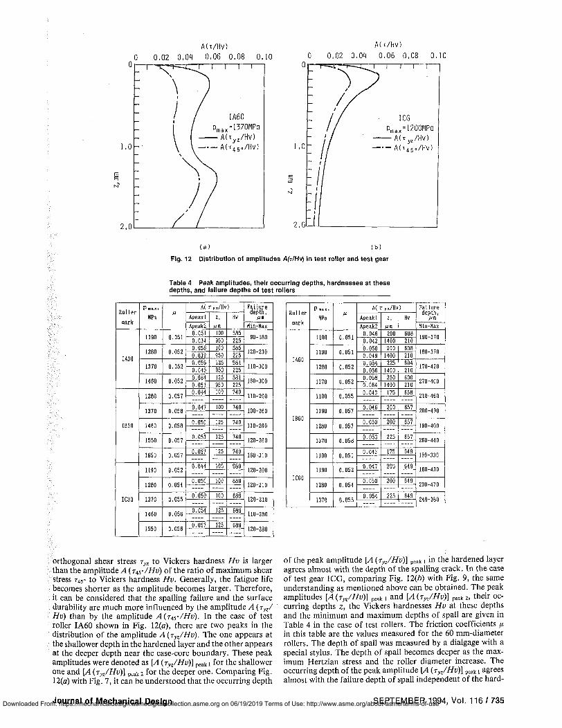
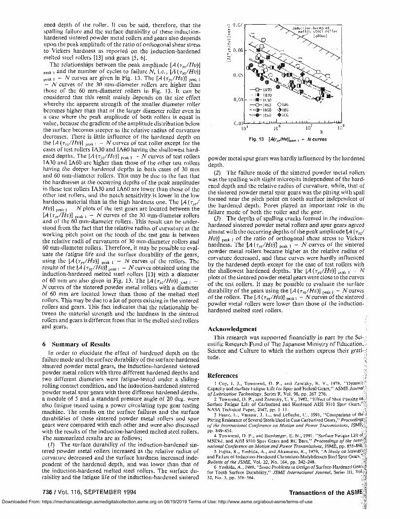
The calculated distributions of the amplitudes A (TlHv) in;]test roller IA60 are shown in Fig. 12(a) under a maximum:Hertzian stress of 1370 MPa, and those in test gear ICG are!:shown in Fig. 12(b) under a maximum Hertzian stress of 1200.;MPa. In both cases, the amplitude A (TyzIHv) of the ratio o~~
Fig. 11 SEM fractographic observation of failed tooth
ating fatigue test, at the early stage of the fatigue process thegrinding marks in the tooth trace direction of the gear disappeared and the micropits appeared at dedendum flanks, andafter that, the micropits spread over the tooth surfaces andspalled area also appeared.
From the observations of Fig. 6 to Fig. 11, it can be concluded that the failure mode of these test rollers is the spaIIingdue to the subsurface origin crack with micropits, while, thefailure mode of these test gears is the pitting due to detachingpowder particle from the tooth surface with spall. The reasonswhy the pitting occurred more easily in the case of the testgears than in the case of the test rollers might be mainly dueto the tip interference between the test gear pair.
•'J
~.
~.. :
\ 1'-on-\1ork !Ilg
(ol
Rotating dIrection.,
Fig. 9 Transverse section of failed tooth
, .
Fig. 10 SEM fractographic observation of failed roller
Concerning the change on the test roller surfaces during therolling contact fatigue test, at the early stage of the fatigueprocess the grinding marks disappeared and the surface wassmoothed, and after that, the roller surface was hardly changedupto the final stage of the fatigue process.
Figure 11 shows a SEM fractographic observation on thefailed tooth of test gear lAG tested under a maximum Hertzianstress of 1200 MPa. In photograph (a) showing the whole failedtooth surface, a spall can be observed near the working pitchpoint and many small pits are also observed especially on thededendum flank. Photographs (b) and (c) were taken frompositions 1and 2 at the bottom of the spall. The rough fracturesurfaces can be observed in these photographs, and the tonguepatterns can be observed clearly in photograph (c). In photograph (d) showing a magnified one taken from the dedendumflank where many pits occurred, the micro surface cracks canalso be observed. These tendencies of microfractographic observations were almost independent of the hardened depth ofthe test gear.
Concerning the change on tooth surfaces during the oper-
734/ Vol. 116, SEPTEMBER 19941
Transactions of the ASME J
Downloaded From: https://mechanicaldesign.asmedigitalcollection.asme.org on 06/19/2019 Terms of Use: http://www.asme.org/about-asme/terms-of-use
0
A(T/HV)
Q 0,02 0,04 0,06 0,08 0.10 i — i — r ~ i — r
A(t/Hv) 0 0,02 0,04 0,06 0,08 0,10
,0 -
M _
2.0
T"
IA60 Pmax=1370MPa A(tyz/Hv) A(t45o/Hv)
i — i — i — i — r
ICG Pmax=1200MPa — Att^/Hv) • - A ( T 4 5 . / H V )
( a ) ( b )
Fig. 12 Distribution of amplitudes A(T/HV) in test roller and test gear
Table 4 Peak amplitudes, their occurring depths, hardnesses at these depths, and failure depths of test rollers
Roller
«ark
IA30
IB30
IC30
P a x ,
HPa
1190
1280
1370
1460
1280
1370
1460
1550
1650
1190
1280
1370
1460
1550
M
0.051
0.052
0.052
0.052
0.057
0.058
0.058
0.057
0.057
0.052
0.054
0.055
0.056
0.056
A(r„/Hv)
Apeak 1
Apeak2 0.051 0.034 0.056 0.039 0.059 0.045 0.064 0.051 0.044
0.047
0.050
0.053
0.057
0.044
0.050
0.050
0.054
0.057
z,
100 950 100 950 125 950 125 950 100
100
125
125
125
100
100
— 100
— 125
125
Hv
585 225 585 225 581 225 581 225 740
740
740
740
740
689
689
689
689
689
Failure depth,
jUfl
Hin-Kax
90-180
120-230
110-300
160-300
110-200
100-260
130-260
120-260
160-310
120-200
120-210
120-210
110-280
120-280
Roller
nark
IA60
IB60
IC60
P a , ,
HPa
1100
1190
1280
1370
1100
1190
1280
1370
1100
1190
1280
1370
M
0.051
0.051
0.052
0.052
0.055
0.057
0.057
0.058
0.051
0.052
0.054
0.055
A(r„/Hv
Apeak 1 Apeak2
0.046 0.042 0.050 0.049 0.054 0.056 0.058 0.064j 0.043
0.046
0.050
0.053
0.043
0.047
0.050
0.054
z, MO
200 1400 200
1400 225
1400 250
1400 175
200
200
225
175
200
200
225
) Hv
608 210 608 210 604 210 600 210 658
657
657
657
649
649
649
649
Failure depth,
Hin-Hax
190-370
180-370
170-420
270-400
210-460
200-490
190-400
260-440
190-330
160-430
200-470
240-380
orthogonal shear stress ryz to Vickers hardness Hv is larger than the amplitude A ( T^/HV) of the ratio of maximum shear stress 745° to Vickers hardness Hv. Generally, the fatigue life becomes shorter as the amplitude becomes larger. Therefore, it can be considered that the spalling failure and the surface durability are much more influenced by the amplitude A (ryz/ Hv) than by the amplitude A(r^/Hv). In the case of test roller IA60 shown in Fig. 12(a), there are two peaks in the distribution of the amplitude A (ryz/Hv). The one appears at the shallower depth in the hardened layer and the other appears at the deeper depth near the case-core boundary. These peak amplitudes were denoted as [A (ryz/Hv)] peaki for the shallower one and [A (ryz/Hv)\ peai<2 for the deeper one. Comparing Fig. 12(a) with Fig. 7, it can be understood that the occurring depth
of the peak amplitude [A (ryz/Hv)] peak I in the hardened layer agrees almost with the depth of the spalling crack. In the case of test gear ICG, comparing Fig. 12(6) with Fig. 9, the same understanding as mentioned above can be obtained. The peak amplitudes [A(ryz/Hv)] peak i and [A(ryz/Hv)] peak2, their occurring depths z, the Vickers hardnesses Hv at these depths and the minimum and maximum depths of spall are given in Table 4 in the case of test rollers. The friction coefficients n in this table are the values measured for the 60 mm-diameter rollers. The depth of spall was measured by a dialgage with a special stylus. The depth of spall becomes deeper as the maximum Hertzian stress and the roller diameter increase. The occurring depth of the peak amplitude [A (ryz/Hv)] peak i agrees almost with the failure depth of spall independent of the hard-
Journal of Mechanical Design SEPTEMBER 1994, Vol. 116 / 735 Downloaded From: https://mechanicaldesign.asmedigitalcollection.asme.org on 06/19/2019 Terms of Use: http://www.asme.org/about-asme/terms-of-use
ened depth of the roller. It can be said, therefore, that the spalling failure and the surface durability of these induction-hardened sintered powder metal rollers and gears also depends upon the peak amplitude of the ratio of orthogonal shear stress to Vickers hardness as reported on the induction-hardened melted steel rollers [13] and gears [5, 6].
The relationships between the peak amplitude [A{ryz/Hv)\ peak j and the number of cycles to failure N, i.e., [A (ryz/Hv)] peak i - N curves are given in Fig. 13. The [A {ryz/Hv)] peak , - N curves of the 30 mm-diameter rollers are higher than those of the 60 mm-diameter rollers in Fig. 13. It can be considered that this result mainly depends on the size effect whereby the apparent strength of the smaller diameter roller becomes higher than that of the larger diameter roller even in a case where the peak amplitude of both rollers is equal in value, because the gradient of the amplitude distribution below the surface becomes steeper as the relative radius of curvature decreases. There is little influence of the hardened depth on the [A (ryz/Hv)] peak i - N curves of test roller except for the cases of test rollers IA30 and IA60 having the shallowest hardened depths. The [A (ryz/Hv)} peak I - -/V curves of test rollers IA30 and IA60 are higher than those of the other test rollers having the deeper hardened depths in both cases of 30 mm and 60 mm-diameter rollers. This may be due to the fact that the hardnesses at the occurring depths of the peak amplitudes in these test rollers IA30 and IA60 are lower than those of the other test rollers, and the notch sensitivity is lower in the low hardness material than in the high hardness one. The {A (ryz/ Hv)] Peak i - N plots of the test gears are located between the [A(ryz/Hv)] peak t - N curves of the 30 mm-diameter rollers and of the 60 mm-diameter rollers. This result can be understood from the fact that the relative radius of curvature at the working pitch point on the tooth of the test gear is between the relative radii of curvatures of 30 mm-diameter rollers and 60 mm-diameter rollers. Therefore, it may be possible to evaluate the fatigue life and the surface durability of the gears, using the [A(Tyz/Hv)] peak I - N curves of the rollers. The results of the [A {ryz/Hv)] peak i - Ncurves obtained using the induction-hardened melted steel rollers [13] with a diameter of 60 mm are also given in Fig. 13. The [A (ryz/Hv)] peak t -N curves of the sintered powder metal rollers with a diameter of 60 mm are located lower than those of the melted steel rollers. This may be due to a lot of pores existing in the sintered rollers and gears. This fact indicates that the relationship between the material strength and the hardness in the sintered rollers and gears is different from that in the melted steel rollers and gears.
6 Summary of Results
In order to elucidate the effect of hardened depth on the failure mode and the surface durability of the surface-hardened sintered powder metal gears, the induction-hardened sintered powder metal rollers with three different hardened depths and two different diameters were fatigue-tested under a sliding-rolling contact condition, and the induction-hardened sintered powder metal spur gears with three different hardened depths, a module of 5 and a standard pressure angle of 20 deg. were also fatigue tested using a power circulating type gear testing machine. The results on the surface failures and the surface durabilities of these sintered powder metal rollers and spur gears were compared with each other and were also discussed with the results of the induction-hardened melted steel rollers. The summarized results are as follows;
(1) The surface durability of the induction-hardened sintered powder metal rollers increased as the relative radius of curvature decreased and the surface hardness increased independent of the hardened depth, and was lower than that of the induction-hardened melted steel rollers. The surface durability and the fatigue life of the induction-hardened sintered
I ' I I m i l i i i i I m l | I I I I I I I
io 5 i o 6 io7 io'
Fig. 13 lA{r,JHv)]peilk, - N curves
powder metal spur gears was hardly influenced by the hardened depth.
(2) The failure mode of the sintered powder metal rollers was the spalling with slight micropits independent of the hardened depth and the relative radius of curvature, while, that of the sintered powder metal spur gears was the pitting with spall formed near the pitch point on tooth surface independent of the hardened depth. Pores played an important role in the failure mode of both the roller and the gear.
(5) The depths of spalling cracks formed in the induction-hardened sintered powder metal rollers and spur gears agreed almost with the occurring depths of the peak amplitude [A (ryz/ Hv)] peak i of the ratio of orthogonal shear stress to Vickers hardness. The [A (ryz/Hv)] peak i - N curves of the sintered powder metal rollers became higher as the relative radius of curvature decreased, and these curves were hardly influenced by the hardened depth except for the case of test rollers with the shallowest hardened depths. The [A{ryz/Hv)] peak x - N plots of the sintered powder metal gears were close to the curves of the test rollers. It may be possible to evaluate the surface durability of the gears using the [A(rn/Hv)] peak i - N curves of the rollers. The [A (ryz/Hv)\ peak \ - A"curves of the sintered powder metal rollers were lower than those of the induction-hardened melted steel rollers.
Acknowledgment This research was supported financially in part by the Sci
entific Research Fund of The Japanese Ministry of Education, Science and Culture to which the authors express their gratitude.
References 1 Coy, J. J., Townsend, D. P., and Zaretsky, E. V., 1976, "Dynamic
Capacity and Surface Fatigue Life for Spur and Helical Gears," ASME Journal of Lubrication Technology, Series F, Vol. 98, pp. 267-276.
2 Townsend, D. P., and Zaretsky, E. V., 1982, "Effect of Shot Peening on Surface Fatigue Life of Carburized and Hardened AISI 9310 Spur Gears," NASA Technical Paper, 2047, pp. 1-11.
3 Faure, L., Vasseur, J. L., and Lefleche, C , 1991, "Comparison of the Pitting Resistance of Several Steels Used in Case Carburized Gears,'' Proceedings of the International Conference on Motion and Power Transmissions, JSME, pp. 849-854.
4 Townsend, D. P., and Bamberger, E. N., 1991, "Surface Fatigue Life of M50NiL and AISI 9310 Spur Gears and RC Bars," Proceedings of the International Conference on Motion and Power Transmissions, JSME, pp. 855-860.
5 Fujita, K., Yoshida, A., and Akamatsu, K., 1979, "A Study on Strength and Failure of Induction-Hardened Chromium-Molybdenum Steel Spur Gears,' Bulletin of the JSME, Vol. 22, No. 164, pp. 242-248.
6 Yoshida, A., 1989, "Some Problems in Design of Surface-Hardened Gears for Tooth Surface Durability," JSME International Journal, Series III, Vol. 32, No. 3, pp. 356-364.
736 / Vol. 116, SEPTEMBER 1994 Transactions of the ASME
Downloaded From: https://mechanicaldesign.asmedigitalcollection.asme.org on 06/19/2019 Terms of Use: http://www.asme.org/about-asme/terms-of-use

7 Fujita, K., Yoshida, A., Kanehara, T., Kominami, K., and Ota, K., 1985, "Study on the Effect of Tooth Fatigue on Dynamic Performance of Gear Pair (2nd Report, In the Case of Case-Hardened Chromium Molybdenum Steel Gears)," Bulletin of the JSME, Vol. 28, No. 236, pp. 322-328.
8 Townsend, D. P., 1987, "Surface Fatigue and Failure Characteristics of Hot-Forged Powder Metal AISI4620, AISI4640 and Machined AISI4340 Steel Spur Gears," Journal of the Society of Tribologists. and Lubrication Engineers, Vol. 43, No. 9, pp. 706-716.
9 Whitehead, J. A., Nurthen, P. D., and Brewin, P. R., 1990, "Rolling Contact Fatigue Testing of P/M High Speed Steels," The International Journal of Powder Metallurgy, Vol. 26, No. 4, pp. 345-349.
10 Yoshida, A., Ohue, Y., Saitoh, M., and Karasuno, I., 1991, "A Study on Surface Durability of Induction-Hardened Sintered Powder Metal Rollers (Influences of Powder Type, Sign of Specific Sliding and Relative Radius of
Curvature)," JSME International Journal, Series HI, Vol. 34, No. 3, pp. 419-426.
11 Yonetani, S., 1971, "On the Method of Measurement of Residual Stress in a Hollow Cylinder by X-Ray Method," (in Japanese), / . Soc. Mater. Sci. Jpn., Vol. 18, No. 190, pp. 610-614.
12 Fujita, K., Yoshida, A., Yamamoto, T., and Yamada, T., 1977, "The Surface Durability of the Case-Hardened Nickel Chromium Steel and Its Optimum Case Depth," Bulletin of the JSME, Vol. 20, No. 140, pp. 232-239.
13 Fujita, K., Yoshida, A., and Nakase, K., 1979, "Surface Durability of Induction-Hardened 0.45 Percent Carbon Steel and Its Optimum Case Depth," Bulletin of the JSME, Vol. 22, No, 169, pp. 994-1000.
14 Smith, J. O., and Liu, C. K., 1953, "Stresses Due to Tangential and Normal Loads on an Elastic Solid with Application to Some Contact Stress Problems," Transactions of the ASME, Vol. 20, No. 2, pp. 157-166.
Fundamental Concepts in Wind Turbine Engineering Wind Turbine Technology is the authoritative guide to state-of-the-art wind turbine e d i t e d b y Dav id A Spera engineering. Using detailed case study analyses, expert authors present practical lessons ' learned from the use of existing wind turbines. Packed with applications-oriented advice, and including numerous graphics and numerical examples—this important reference offers descriptions of past and present wind turbine configurations and provides the reader with mathematical models developed from basic principles. This invaluable information is presented by leaders in the fields of aerodynamics, structural dynamics and fatigue, meteorology, acoustics and electromagnetic emissions, commercial wind power applications, and utility power systems. Discussions of economic and environmental considerations and the integration of wind power plants into electric utility systems are included as well. In 13 chapters, Wind Turbine Technology covers a full range of the most important topics, including:
IIH^
I I *
commercial wind turbines and applications wind turbine airfoils and rotor wakes characteristics of the wind structural dynamic considerations in wind turbine design fatigue design of wind turbines _,•,,..
*• aerodynamic behavior of wind turbines *• wind turbine acoustics * electromagnetic Interference from wind turbines *• structural dynamic behavior of wind turbines * utility perspectives on wind energy
If you are an energy planner, engineer, designer, utility project manager, wind power plant developer, or manufacturer of wind turbine equipment, Wind Turbine Technology has all the latest information you need and is ideal for educational settings as well.
List Price $90 • Member Price $72 • Order Number 100368
In the U.S ./Canada: (800) THE ASME, ext. 611
(800 843 "2763|
In Mexico: 95, (800) 843 2763, ext. 611
Outside North America: (201J 882 1167, ext. 611
= 1 Write: ASME, Dept. MH, 22 Law Drive, Box 2900, Fairfield, NJ 07007-2900
Email: [email protected]
Fax: (201)882 1717 or (201) 882 5155
Journal of Mechanical Design SEPTEMBER 1994, Vol. 116 / 737 Downloaded From: https://mechanicaldesign.asmedigitalcollection.asme.org on 06/19/2019 Terms of Use: http://www.asme.org/about-asme/terms-of-use