_V_Design relevant properties of hardened Ulra High ...
12
1 Ekkehard Fehling Prof. Dr.-Ing. Universität Kassel Kassel, Germany Kai Bunje Dipl.-Ing. Fehling - Jungmann GmbH Kassel, Germany Torsten Leutbecher Dipl.-Ing. Universität Kassel Kassel, Germany Design relevant properties of hardened Ultra High Performance Concrete Summary Ultra High Performance Concrete (UHPC) offers a great spectrum of favourable material proper- ties. The structural behaviour of UHPC differs from normal- or high-strength concrete, particu- larly for a supplement of fibres. In most countries valid design rules for this new material do not yet exit. In Germany a work group of the German Commission on Reinforced Concrete (Deutsche Ausschuss für Stahlbeton DAfStb) has presented a state of the art report on UHPC [1]. Chapter 6 of this report describes the knowledge about the properties of hardened UHPC. This paper summarises some of the main aspects dealt with there. Keywords: material properties, shrinkage, creep, fatigue behaviour, bond, fire resistance 1 Introduction The properties of hardened Ultra High Performance Concrete (UHPC) [2] are determined by the very dense structure of this material. The microstructure of UHPC differs significantly from nor- mal- and high-strength concrete. With respect to the mechanical behaviour, UHPC with fibres shows, depending on the type and quantity of fibres contained in the mix, ductile behaviour un- der compression as well as in tension. In contrast to this, UHPC without fibres behaves brittle, if no additional measure such as confinement is chosen. Since the pre-peak behaviour does not show significant differences, the elastic properties of UHPC with and without fibres can be de- scribed in common whereas the influence of fibres has to be described separately. As one consequence of the dense structure of UHPC, the porosity of UHPC is much lower than for normal- and even for high-strength concrete. Another consequence is the improvement of
-
Upload
khangminh22 -
Category
Documents
-
view
0 -
download
0
Transcript of _V_Design relevant properties of hardened Ulra High ...

1
Ekkehard Fehling Prof. Dr.-Ing. Universität Kassel Kassel, Germany Kai Bunje Dipl.-Ing. Fehling - Jungmann GmbH Kassel, Germany Torsten Leutbecher Dipl.-Ing. Universität Kassel Kassel, Germany
Design relevant properties of hardened Ultra High Performance Concrete
Summary
Ultra High Performance Concrete (UHPC) offers a great spectrum of favourable material proper-ties. The structural behaviour of UHPC differs from normal- or high-strength concrete, particu-larly for a supplement of fibres. In most countries valid design rules for this new material do not yet exit. In Germany a work group of the German Commission on Reinforced Concrete (Deutsche Ausschuss für Stahlbeton DAfStb) has presented a state of the art report on UHPC [1]. Chapter 6 of this report describes the knowledge about the properties of hardened UHPC. This paper summarises some of the main aspects dealt with there. Keywords: material properties, shrinkage, creep, fatigue behaviour, bond, fire resistance
1 Introduction
The properties of hardened Ultra High Performance Concrete (UHPC) [2] are determined by the very dense structure of this material. The microstructure of UHPC differs significantly from nor-mal- and high-strength concrete. With respect to the mechanical behaviour, UHPC with fibres shows, depending on the type and quantity of fibres contained in the mix, ductile behaviour un-der compression as well as in tension. In contrast to this, UHPC without fibres behaves brittle, if no additional measure such as confinement is chosen. Since the pre-peak behaviour does not show significant differences, the elastic properties of UHPC with and without fibres can be de-scribed in common whereas the influence of fibres has to be described separately. As one consequence of the dense structure of UHPC, the porosity of UHPC is much lower than for normal- and even for high-strength concrete. Another consequence is the improvement of

2
the contact zones between the cement matrix and the aggregates as well as the fibre rein-forcement which allows a short length of fibres. This is illustrated by Figure 1 showing the good bond between the different components (a and b). Figure 1c shows a situation which can often be found in normal-strength concrete. The dense structure is also responsible for the very low permeability for gases and fluids and hence superior durability of this material. The low permeability has an adverse effect with respect to fire resistance. This, however, can be compensated as shown in chapter 8.
a) good bond between cement matrix and quartz sand particles (left) b) exceptional bond between matrix and steel fibre c) less satisfactory bond between matrix and quartz sand particle (right)
Figure 1: Contact zones in UHPC between matrix and aggregates or fibres
2 Behaviour under Compression
The typical compressive strength of UHPC is in the range of 150 to 220 MPa. Until about 70 to 80 % of the compressive strength, UHPC shows a linear elastic behaviour (Figure 2). According to experimental evidence as obtained until now, this holds true for UHPC regardless of the maximum aggregate size. The failure of UHPC without fibres is of explosive nature. No de-scending branch in the stress-strain-diagram does exist. This, however, can also be observed for HSC with fc > 90 MPa.
Stress-Strain-Diagram of UHPC without fibres
Concrete strain
Com
pres
sive
stre
ss
fc
~0,70 - 0,80 fc
εc1
1
E � 45 - 55 GPa
Figure 2: Stress-strain-diagram of UHPC without fibres

3
Due to the dense structure, the elastic modulus of UHPC is higher than for normal- and high- strength concrete when using identical aggregate types. Figure 3 shows typical results as ob-tained at Leipzig University [1].
Figure 3: Elastic modulus versus compressive strength
The Poisson ratio in general has been determined to be about 0.2 in the linear elastic range.The strain at peak stress for UHPC with fine aggregates amounts to approximately 4.4 ‰. For basal-tic aggregates or e. g. DENSIT-UHPC using bauxite, lower values have to be expected. For UHPC with fibres (UHPFRC), a pronounced descending branch can be developed by the effect of the fibres (Figure 4). The slope of the descending branch depends on
- fibre content, - fibre geometry (length, diameter), - fibre length in relation to maximum aggregate size, - fibre stiffness (in case of fibre cocktails) and - fibre orientation.
Although in general the influence of fibres on the compression strength is low. Due to 2.5 vol.-% of fibres, an increase of the compressive strength of about 15 % has been noted [3]. For UHPC, the geometry of test specimens seems to have less influence on the compressive strength. However, contradictory results from different sources exist with respect to this ques-tion. Heat treatment can speed up the development of the compressive strength. At 250 °C, a signifi-cant increase of the strength can be obtained, since the high temperature does not only accel-erate the chemical reaction but also leads to an improvement of the microstructure. According to [1 ,3], even at 90°C heat treatment lasting 48 hours will enable higher compressive strength values than for the case of curing 28 days in water.
Ultrahochfester Feinkornbeton:Ecm = 19000 (fc/10)1/3
R2 = 0,8878
25000
30000
35000
40000
45000
50000
55000
60000
1,7 1,9 2,1 2,3 2,5 2,7 2,9
Ecm
(N/m
m²)
HPC mit Sand-Kies-Zuschlag: Ecm=20500 (fc/10)1/3
49 19712269 93 156 244fc,zyl100*200
(fc/10)1/3
Ultra High Strength Concrete with fine aggregates Ecm = 19000 (fc/10)1/3 R2 = 0,8878
HPC with sand/gravel aggregates: Ecm = 20500 (fc/10)1/3

4
UHPC with fibres, 1,0 Vol.% - 2,5 Vol.%stess-strain diagram
Concrete strain
Com
pres
sive
stre
ssfc2
fc1
εc1 εc2
Range of possible descending depending on fibre amountand fibre orientation
E � 45 - 55 GPa
1
Figure 4: Typical stress-strain-diagrams of UHPFRC
3 Behaviour in Tension
The tensile strength can be determined experimentally using prismatic or cylindrical specimens. It may be advantageous to use probes sawn out of plates. In principle, it is possible to use specimens with or without notches. Direct tension tests on UHPC without fibres have delivered tensile strength values between 7 and 10 MPa. According to results obtained at the Universities of Kassel and Leipzig, there are only small differences between UHPC with fine or coarse aggregates. The failure is rather brit-tle, hence without a significant descending branch. Depending on the amount, type and orientation of fibres, the tensile strength of UHPFRC can be increased beyond the matrix strength. Values in the range between 7 and 15 MPa [3] have been recorded. Due to the effect of fibres, the behaviour becomes ductile. After onset of crack-ing, the material may be characterised by the stress-crack-opening-diagram. The typical behav-iour is depicted in Figure 5. It should be noted, that the slope of the descending branch can be very different, depending on the fibre orientation and the content and type of fibres.
Tensile strength - UHPC with fibres
Crack opening
Tens
ile s
tress
fc,t
2
fc,t
1
Range of possible descending depending on fibre amountand fibre orientation
good fibre orientationwithout fibres
Figure 5: Typical stress-crack-opening-curve for UHPC

5
In [1], a formula for the estimation of the splitting tensile strength in dependency on the com-pressive strength is given. Furthermore, the axial tensile strength may be derived from the bending tensile strength considering the size effect.
Figure 6: Standard bending test according to DAfStb-Guideline on Steel-Fibre Concrete [4]
In order to simplify the testing procedure for tensile properties, the DAfStb-Guideline on Steel-Fibre Concrete [4] defines a test setup which allows the determination of the tensile strength as well as a stress-crack-opening-relationship. This is possible, since in general only one crack opens significantly so that the bending deformation is concentrated there and the crack opening is almost proportional to the deflection. Furthermore, a method to transform the stress-crack-opening-relationship into a stress-strain-relationship is presented in these guidelines. Figure 7 shows the typical result as obtained from bending tests, see [1].
Bending tensile strength - UHPC with fibres
Crack opening
Ben
ding
tens
ile s
tress fc,t
2
fc,t
1
Range of possible descending depending on fibre amount and fibre orientation
good fibre direction
bad fibre direction
Figure 7: Typical results from bending tensile tests
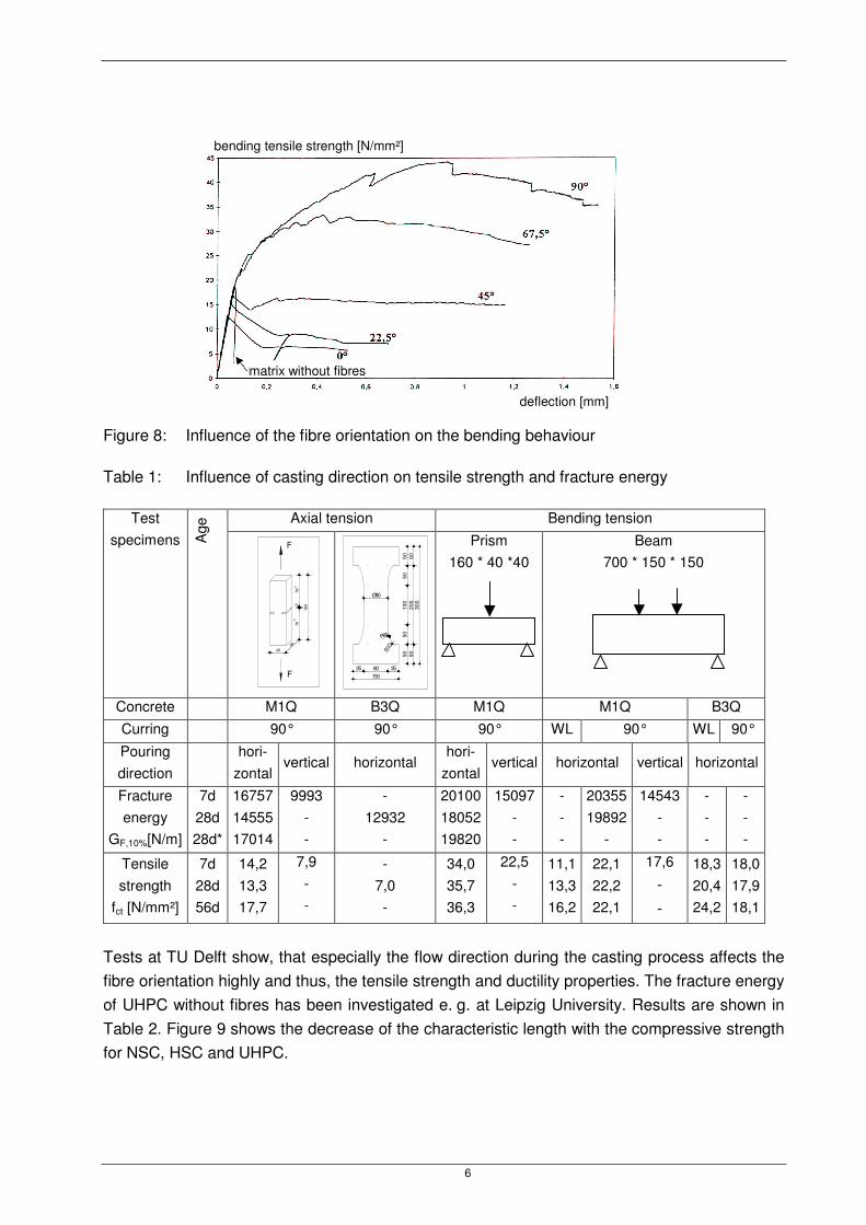
The influence of the fibre orientation has been studied by Bernier und Behloul [1], see Figure 8. The influence of the fibre orientation is also picted in Table 1, where different types of speci-mens with vertical and horizontal pouring direction are compared.
6
Figure 8: Influence of the fibre orientation on the bending behaviour
Table 1: Influence of casting direction on tensile strength and fracture energy
Axial tension Bending tension Test specimens A
ge
Ø80
R10
R90
5050
100
5050
5020
050
300
35 80 35150
Prism 160 * 40 *40
Beam 700 * 150 * 150
Concrete M1Q B3Q M1Q M1Q B3Q Curring 90° 90° 90° WL 90° WL 90°
Pouring direction
hori-
zontal vertical horizontal
hori-zontal
vertical horizontal vertical horizontal
Fracture energy
GF,10%[N/m]
7d 28d 28d*
16757 14555 17014
9993 - -
- 12932
-
20100 18052 19820
15097 - -
- - -
20355 19892
-
14543 - -
- - -
- - -
Tensile strength
fct [N/mm²]
7d 28d 56d
14,2 13,3 17,7
7,9 - -
- 7,0 -
34,0 35,7 36,3
22,5 - -
11,1 13,3 16,2
22,1 22,2 22,1
17,6
- -
18,3 20,4 24,2
18,0 17,9 18,1
Tests at TU Delft show, that especially the flow direction during the casting process affects the fibre orientation highly and thus, the tensile strength and ductility properties. The fracture energy of UHPC without fibres has been investigated e. g. at Leipzig University. Results are shown in Table 2. Figure 9 shows the decrease of the characteristic length with the compressive strength for NSC, HSC and UHPC.
F
F
783
78
160
40
55
40
bending tensile strength [N/mm²]
deflection [mm]
matrix without fibres

7
Table 2: Fracture parameters of UHPC for different mix designs
Mortar 1 Mortar 2 Mortar 3
selfcompacting
fine-grained
concrete
compacted fine-
grained concrete
UHPC with
basalt grain
Cylinder compressive strength
[N/mm²] 40 81,2 106,6 149,1 196,3 145,0
Fracture energy GF [(N/m] 53,7 65,1 66,5 62,8 54,7 95,0
Tensile strength [N/mm²], fct=0,9fct,sp 3,2 6,1 8,0 9,4 11,9 8,3
Characteristic length lch [mm] 133,5 61,3 44,7 32,6 20,1 80,6
Softening function bilinear bilinear Linear linear linear bilinear
Limit crack width [µm] 79,2 65,6 15,1 13,2 9,8 127,2
Figure 9: Characteristic length lch versus compressive strength
0
50
100
150
200
250
300
350
400
450
10 20 30 40 50 60 70 80 90 100 110 120 130 140 145 149 196
Druckfestigkeit (N/mm²)
char
akte
ristis
che
Läng
e (m
m)
UH
FB m
it B
asal
tspl
itt
Fein
korn
beto
n
Fein
korn
beto
n
Compressive Strength [N/mm²]
Cha
ract
eris
tic L
engt
h l ch
[mm
]
UH
PC
with
bas
altic
spl
it
fine-
aggr
egat
ed c
oncr
ete
fine-
aggr
egat
ed c
oncr
ete

8
4 Time dependant Properties
4.1 Shrinkage
According to data from Kassel and Leipzig [1, 3], the total shrinkage of sealed UHPC with fine aggregates amounts to 0.7 mm/m under isothermal conditions in the first seven days after pour-ing. Until an age of 28 days, the total shrinkage increases to about 0.9 mm/m. The influence of steel fibres on the autogenous shrinkage is of minor importance. Figure 10a and b give exam-ples for the development of shrinkage versus time.
Figure 10: Development of shrinkage versus time
The development of drying shrinkage of UHPC is similar as of HPC. Due to the high density of the matrix structure, however, the amount of drying shrinkage is reduced in comparison to HPC. For heat treated UHPC, drying shrinkage can practically be neglected after the end of the heat treatment.
-600
-500
-400
-300
-200
-100
0
0 100 200 300 400 500 600 700
Zeit ab höchster Betontemperatur (Std.)
auto
gene
s S
chw
inde
n ab
Tm
ax (
µm/m
)
UHFB mit Basaltsplitt (CEM I 42,5R-HS)Feinkorn-UHFB (CEM I 42,5R)
Probekörper: 150*150*700 mm
UHPC with basaltic split (CEM I 42,5R-HS)
fine-aggregated UHPC (CEM I 42,5R) test specimes: 150*150*700 mm
time, starting at highest concrete temperature [h]
auto
geno
us s
hrin
kage
, st
artin
g at
Tm
ax [µ
m/m
]
b)
UHPC with basaltic split (CEM I 42,5R-HS) fine-aggregated UHPC (CEM I 42,5R)
test specimens: 150*150*700 mm
UHPC with basaltic split (CEM I 42,5R-HS)
fine-aggregated UHPC (CEM I 42,5R)
-1200
-1000
-800
-600
-400
-200
0
0 100 200 300 400 500 600 700
Zeit nach Betonage (Std.)
Läng
enän
deru
ng (
µm/m
)
UHFB mit Basaltsplitt (CEM I 42,5R-HS)Feinkorn-UHFB (CEM I 42,5R)
Zeitpunkt der Tmax
Probekörper: 150*150*700 mmtest specimes: 150*150*700 mm
time Tmax
time after concreting [h]
elon
gatio
n [µ
m/m
]
a)
UHPC with basaltic split (CEM I 42,5R-HS) fine-aggregated UHPC (CEM I 42,5R)
test specimens: 150*150*700 mm
time Tmax
9
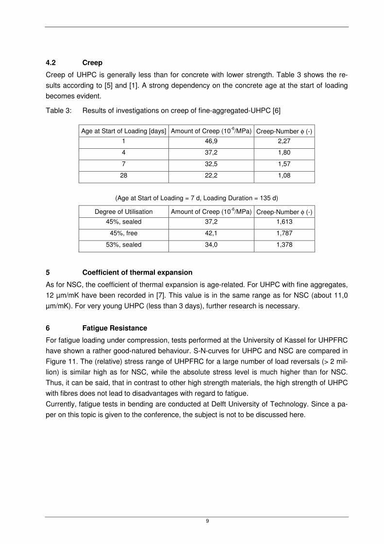
4.2 Creep
Creep of UHPC is generally less than for concrete with lower strength. Table 3 shows the re-sults according to [5] and [1]. A strong dependency on the concrete age at the start of loading becomes evident.
Table 3: Results of investigations on creep of fine-aggregated-UHPC [6]
Age at Start of Loading [days] Amount of Creep (10-6/MPa) Creep-Number φ (-) 1 46,9 2,27
4 37,2 1,80
7 32,5 1,57
28 22,2 1,08
(Age at Start of Loading = 7 d, Loading Duration = 135 d)
Degree of Utilisation Amount of Creep (10-6/MPa) Creep-Number φ (-) 45%, sealed 37,2 1,613
45%, free 42,1 1,787
53%, sealed 34,0 1,378
5 Coefficient of thermal expansion
As for NSC, the coefficient of thermal expansion is age-related. For UHPC with fine aggregates, 12 µm/mK have been recorded in [7]. This value is in the same range as for NSC (about 11,0 µm/mK). For very young UHPC (less than 3 days), further research is necessary.
6 Fatigue Resistance
For fatigue loading under compression, tests performed at the University of Kassel for UHPFRC have shown a rather good-natured behaviour. S-N-curves for UHPC and NSC are compared in Figure 11. The (relative) stress range of UHPFRC for a large number of load reversals (> 2 mil-lion) is similar high as for NSC, while the absolute stress level is much higher than for NSC. Thus, it can be said, that in contrast to other high strength materials, the high strength of UHPC with fibres does not lead to disadvantages with regard to fatigue. Currently, fatigue tests in bending are conducted at Delft University of Technology. Since a pa-per on this topic is given to the conference, the subject is not to be discussed here.

10
Figure 11: S-N-curves for UHPC in comparison to NSC
7 Bond of Reinforcement
Due to the high compressive strength and the high density, UHPC enables very high bond stresses. For smooth fibres (l = 13 mm, Ø = 0.15/0.2 mm), Behloul [1] reports a value of fb = 11.5 MPa for BPR (DUCTAL). For prestressing wires and strands, the maximum bond stress depends on the concrete cover (see Figure 12)
Figure 12: Bond strength for prestressing strands (∅ 12,5 mm) depending on contact length to diameter according to [Cheyrezy, Roux, Behloul, Ressicaud and Demonte (1998)]
max. bond stress [N/mm²] max. bond stress [N/mm²]
bond length L/d concrete cover c/d
max. bond stress [N/mm²] max. bond stress [N/mm²]
bond length L/d with c/d = 4.8 concrete cover c/d with L/d = 5.6
0,20
0,30
0,40
0,50
0,60
0,70
0,80
0,90
1E+02 1E+03 1E+04 1E+05 1E+06 1E+07 1E+08 1E+09 1E+10 1E+11 1E+12
stress reversals [-]
non
- dim
ensi
onal
rang
e 2�
a/f c
[-]
UHPC �u = (0,06 bis 0,075) fc = const.
UHPC �u = (0,21bis0,25) fc = const.
NC �u = 0,05 fc = const. [5]
NC �u = 0,20 fc = const. [5]NC �u = 0,05 fc = const. [6]

11
For ribbed reinforcing bars, test results are available from Weiße in Leipzig and Greiner/Reineck (University of Stuttgart, Figure 13). Very high bond stresses in the range of 40 to 70 MPa have been reported. In tests on rebars with 10 mm diameter, Weiße observed splitting failure in the concrete cover for a cover less than 25 mm. Due to the high bond stresses, the bond length in
the standard RILEM pull-out specimen has to be reduced to 2 ∅ instead of 5 ∅ (see Figure 14).
Otherwise, no pull-out would be feasible before the yielding of steel. Weiße used 1.5 ∅ for his tests.
Figure 13: Bond-stress-slip-relationship of UHPC according to Reineck and Greiner [1]
Figure 14: Modified RILEM pull-out test
0
10
20
30
40
50
0,0 0,5 1,0 1,5 2,0 2,5 3,0
Verschiebung am lastfreien Ende [mm]
Ver
bund
span
nung
[N/m
m²]
Würfel 40 mm aus Ductal, 2 Vol-% Fasern,gerippter Stabstahl Ø = 4 mm, Verbundlänge 2Ø = 8 mm
disp
lace
men
t at t
he u
nloa
ded
end
[mm
]
cube 40 mm of Ductal, 2 vol.-% fibres, ribbed reinforcement bar ∅ = 4 mm, bond length 2 ∅ = 8 mm
displacement at the unloaded end [mm]
load direction
located in the centre of the specimen
12
8 Fire Resistance
Due to the extremely high density of UHPC, high water pressure can arise when UHPC is ex-hibited to fire. This can lead to deterioration of the concrete structure. The problem can be over-come by the use of fibres, e. g. polypropylene fibres. One effect of the fibres is that they create capillary pores due to melting and burning. Furthermore, around the fibres transition zones to the cement matrix are formed. By this, the existing transition zones between aggregates and matrix are interlinked so that the permeability increases and the steam pressure is reduced. Experiments have shown the effectivity of adding polypropylene fibres [8, 9, 10, 11]. Another problem is associated with the anomaly of quartzitic compounds with respect to the
volumetric expansion occurring at 573 °C due to the change of crystal phases (α-quartz to β-quartz). Good results could be obtained by replacing quartz by basalt [12].
9 References
[1] Sachstandsbericht Ultrahochfester Beton - Betontechnik und Bemessung - in preparation, Deutscher Ausschuss für Stahlbeton im DIN Deutsches Institut für Normung e. V., 2004.
[2] Bornemann, R.; Schmidt, M.; Fehling, E.; Middendorf, B.: Ultra-Hochleistungsbeton UHPC – Herstel-lung, Eigenschaften und Anwendungsmöglichkeiten. Beton- und Stahlbetonbau 96, No. 7, p. 458-467, 2001.
[3] Fehling, E.; Schmidt, M.; Teichmann, T.; Bunje, K.: Entwicklung, Dauerhaftigkeit und Berechnung Ultra-Hochfester Beton (UHPC), Forschungsbericht an die DFG, Universität Kassel, 2003.
[4] DAfStb-Richtlinie Stahlfaserbeton (10. Entwurf), Ergänzungen zu DIN 1045-1, Teile 1 bis 4, March 2003, Deutscher Ausschuss für Stahlbeton im DIN Deutsches Institut für Normung e. V.
[5] AFGC Groupe de travail BFUP: wissenschaftliche und technische Berichte über Ultra High Perfor-mance Fibre-Reinforced Concretes, Zwischenbericht, Frankreich, January 2002.
[6] Ma, J; Schneider, H.: Creep of ultra-high performance concrete under compressive stresses, Leipzig Annual Civil Engineering Report, No. 8, 2003.
[7] Ma, J.; Dehn, F.; König G.: Autogenous shrinkage of self-compacting ultra-high perfomance con-crete, in Proceeding “International Conference on Advances in Concrete and Structures”, May 2004, Xuzhou, P.R. China.
[8] Diederichs, U.: Hochtemperatur- und Brandverhalten von hochfestem Stahlfaserbeton. In: Betonbau Forschung, Entwicklung und Anwendung, No. 142, p. 67-76, TU Braunschweig 1999.
[9] Schneider, U.; Horvath, J.; Dehn, F.: Abplatzverhalten von ultrahochfestem Beton (UHPC) unter Brandbeanspruchung, Leipzig Annual Civil Engineering Report (LACER), No. 6, Universität Leipzig 2001.
[10] Schneider, U.; Horvath, J.; Dehn, F.: Faserbewehrte ultrahochfeste Betone, in: König, G.; Holsche-macher, K.; Dehn, F. (Eds.): Faserbeton - Innovationen im Bauwesen, Bauwerk-Verlag, Berlin 2002.
[11] Dehn, F.; König, G.: Fire Resistance of different Fibre Reinforced High-Performance Concretes, In: Naaman, A; Reinhardt, H.-W.: Workshop HPFRCC 4, Ann Arbor (USA), June 2003.
[12] Bornemann, R.; Schmidt, M.; Vellmer, C.: Feuerwiderstand ultra-hochfester Betone, Beton 52, No. 9, p. 418-422, 2002.