Role of Dopamine D2 Receptors in Human Reinforcement Learning
Upload
khangminh22Category
view
0download
0

HELICAL MILLING: AN ENABLINGTECHNOLOGY FOR MACHINING
HOLES IN FULLY HARDENED AISI D2TOOL STEEL

HELICAL MILLING: AN ENABLING TECHNOLOGY FOR
MACHINING HOLES IN FULLY HARDENED AISI D2
TOOL STEEL
By
RAVISHANKAR IYER, B.ENG.
A Thesis
Submitted to the Faculty of Graduate Studies
in Partial Fulfillment of the Requirements
for the Degree of
Master of Applied Sciences
McMaster University
Copyright by Ravishankar Iyer. B.Eng.. February 2006

Master of Applied Sciences
Mechanical Engineering
McMaster University
Hamilton. Ontario. Canada
TITLE:
AUTHOR:
SUPERVISOR:
NUMBER OF PAGES:
Helical Milling: An Enabling Technology
for Machining Holes in Fully Hardened
AISI D2 Tool Steel.
Ravishankar Iyer, B.Eng.
University of Pune. India, 1998.
Dr. Philip Koshy, Ph.D.
123 pages (i-xv, 1-108)
n

ABSTRACT
The machining of hardened steel is becoming widespread throughout the man
ufacturing industry owing to the benefits derived in the form of manufacturing flexi
bility, better product quality, and the prospect of dry machining. This coupled with
developments in super hard cutting tool materials and machine tools, and better
understanding of hard machining technology translates into significant economical
benefits and faster turnaround times.
The majority of applications involving hardened steels comprising AISI D2 tool
steel relates to the manufacturing of die and mold wherein the current trend of hard
machining is restricted by the limitations imposed by hard drilling. Being the final
operation in many manufacturing applications, it is imperative that the process of
drilling be robust and reliable to enhance the value already added to the product.
Problems associated with inherent deficiencies in the drilling process kinematics, com
bined with poor machinability of hardened D2 tool steels due to the presence of hard
and abrasive carbide particles in its microstructure that lead to catastrophic drill
failure, constitute the single major process chain bottleneck in realizing hard part
manufacture.
The research work presented in this thesis focuses on the application of helical
milling as an enabling technology for hole making in hardened AISI D2 tool steel
in comparison to conventional drilling, which is not feasible at the current level of
developments in drilling technology. Helical milling employs a rotating end mill of a
diameter smaller than the hole, and traverses a helical path to generate a hole. The
novel process derived by simple modification of tooling and process kinematics offers
an excellent avenue to successful machining of precision holes in hardened D2 tool
steel.
In order to compare the performance of helical milling against drilling, four
types of conventional twist drills intended for drilling hardened steels were employed
in the machining experiments while, end mills commonly used in the die and mold
m

industry, were chosen for helical milling. The processes were evaluated in terms of
tool life, wear progression, wear mode, cutting" forces and hole quality.
Accelerated wear followed by catastrophic fracture of the cutting edges at the
periphery of the drill was observed to be the primary tool failure mode in conventional
drilling as opposed to uniform progressive flank wear in helical milling. The innovative
helical milling method is found to facilitate1 hole-making in hardened D2 tool steel
with an order of magnitude improvement in tool life. The helical trajectory of the
tool in helical milling facilitates material removal near and at the center of the hole by
cutting rather than extrusion as seen in drilling, thereby reducing the excessive thrust
forces that cause work material breakouts at the hole exit in conventional drilling.
Furthermore, chip evacuation in not problematic in helical milling considering
that chips can be removed across the radial clearance between the tool and the hole
as opposed to through the flute space in conventional drilling. This implies that an
air blow could be employed to assist chip transport in helical milling facilitating dry
machining, considering that in many drilling applications cutting fluid is merely used
to flush the chips away from the cutting zone1 The intermittent cutting action in
helical milling further provides respite to the cutting edge from the imposed mechan
ical and thermal loads and offers exceptional chip control. The process represents an
enabling technology with additional benefits of superior hole quality thus rendering
the elimination of an additional reaming process.
IV

ACKNOWLEDGMENTS
"The whole art of teaching is only the art of awaken inn the natural cariosity of
young minds for the purpose of satisfying it afterwards."
Anatole France (1844 M-W
This is a perfect synopsis of the supervisory style of Dr. Philip Koshv. to whom
I remain indebted in so many ways than I can state in this small space. An inspiring
teacher and a highly dedicated researcher who believed in me and constantly encour
aged me to realize my potentials and capabilities. I consider myself very fortunate to
have known him as my guru, mentor and friend.
I would also like to express my sincere gratitude to "THAMBI", Dr. Eugene
Xg, for his invaluable support, helpful critiques and discussions during the course of
this work. It is a great pleasure and privilege1 to have gained a valuable friend in him.
I have also had the distinguished opportunity to participate and interact with some
of the most outstanding faculty members of MMRI during the past few years and
thank them for making the association a very valuable and enriching experience.
The financial support extended in the form of scholarship from McMaster Uni
versity. AUTO 21. Xatural Sciences and Engineering Research Council (XSERC) and
McMaster Manufacturing Research Institute (MMRI) is greatly acknowledged. Spe
cial acknowledgements are due to the Machining Systems Laboratory (MSL) team of
Jim McClaren, Miky Dumitrescu and Warren Reynolds for their patience and help
fulness. I would like to express my gratitude to Dave Schick and Ron Lodewyks for
their co-operation and support in times of need. The support extended in the form
cutting tools, necessary for conducting some of the machining experiments in this
research, from Brian Philips of Sandvik Coromant Canada is also highly acknowl
edged. The cooperation and support extended by Sylvia Ragis, Linlin Zhao. Betty
Anne Bedell-Rye, Janet Murphy and Florence Rosato is greatly appreciated.
v

I'm thankful to Maneesh Khanna. Sudheer Patil, Frederick Suresh. Andrew
Weaver. Diaa Elkott. Jeremy Stenekes. Andy Simoneau and all m>- friends and col
leagues at MMRI and the Mechanical Engineering department at McMaster Uni
versity, for their friendship, support and willingness to help even though they were
pressed for time themselves and for making my stay at McMaster very memorable.
I would also like to thank my parents for their love and support and my family,
especially my uncle. Dr. Ramani Ramaseshan and aunt, Dr. Xithya Ramani for their
support and guidance. I would not be at this place in life, if it were not for you both.
The enthusiasm, encouragement and words of wisdom from my beloved eldest uncle.
Mr. Krishnamurthy Xarayan. have always inspired and motivated me and to whom
I remain forever grateful. I would like to express my sincere gratitude towards my
parents-in-law for their support and having faith in my abilities. Last but not the
least, I would like to thank my dear wife Sheet al for her boundless love, unconditional
support and enduring patience during the entire course of this work. None of this
would have been possible without you all.
Hamilton, ON
February 2006 Ravishankar Iyer
VI

Dedicated to my parents, Muralidharan and Chandra
for their unwavering love, faith and encouragement
throughout my life, without which I would not have
been able to achieve my dreams.
VII

CONTENTS
ABSTRACT . . iii
ACKNOWLEDGMENTS v
LIST OF TABLES x
LIST OF FIGURES xi
LIST OF SYMBOLS xiv
1. INTRODUCTION 1
1.1 Research Problem and Motivation 1
1.2 Helical Milling . . 5
1.3 Thesis Outline ... 6
2. BACKGROUND AND LITERATURE REVIEW 8
2.1 Introduction 8
2.2 Overview of Drilling Mechanics 9
2.3 Properties of Alloy Steels 13
2.3.1 Cold Work Tool Steel 14
2.3.2 AISI D2 Tool Steel 15
2.4 Hard Machining .... . . 17
2.5 Review of Machining Hardened AISI D2 19
2.6 Review of Hard Drilling of AISI D2 . 27
2.7 Chapter Synopsis . . . . 31
3. EXPERIMENTAL 33
3.1 Introduction 33
3.2 Work Material and Tooling 34
3.2.1 Conventional Drills 35
3.2.2 Helical Milling Tools 36
3.3 Machine Tool Specification 38
3.4 Material Removal Rate (MRR) 40
viii

3.4.1 MRR Conventional Drilling 41
3.4.2 MRR Helical Milling 42
3.5 Process Strategy and Cutting Parameters . 47
3.5.1 Cutting Parameters . .... 49
3.5.2 Test Conditions and Force Measurement 50
3.6 Chapter Synopsis 52
4. RESULTS AXD DISCUSSION 54
4.1 Introduction . . . . . 54
4.2 Drilling of Hardened AISI D2 55
4.2.1 Wear Modes in Conventional Drilling 55
4.2.2 Twist Drill Geometry . . . 60
4.2.3 Influence of Work Material 65
4.2.4 Possible Drill Geometry Modifications 68
4.3 Helical Milling of Hardened AISI D2 72
4.3.1 WVar Modes in Helical Milling 76
4.3.2 Helical Milling Tool Geometry 83
4.4 Cutting Forces 85
4.5 Hole Accuracy in Helical Milling . . . . 90
4.6 Chapter Synopsis 92
5. CONCLUSIONS AND FUTURE WORK 95
5.1 Conclusions 95
5.2 Scope for Future Work .... 99
REFERENCES . . . . 101
IX

LIST OF TABLES
2.1 Chemical composition of AISI D2 cold work tool steel [20] 16
2.2 Physical properties of AISI D2 tool steel at various temperatures [20]. ... 16
3.1 Tooling used in experimental work. 34
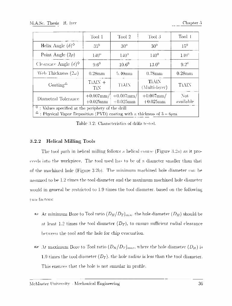
3.2 Characteristics of drills tested. 36
3.3 Configuration of helical milling tools 38
3.4 Machine tool specification. 39
3.5 Drilling parameters. . . . 49
3.6 Helical milling parameters ... 50
x
LIST OF FIGURES
1.1 Surface finish and tolerance obtainable in hard turning [2] 2
1.2 Helical milling process. 5
2.1 Twist drill nomenclature [14] 10
2.2 Chip formation in drilling (a) Along chisel edge (b) Along cutting edges [15]. 11
2.3 Hardening effects of alloying elements dissolved in pure iron [18] [19]. . . 14
2.4 (a) Continuous chip (b) Saw-tooth chip [22]. . . 18
2.5 Microstructure of hardened tool steels: (a) AISI D2. and (b) AISI H13 [25]. 20
2.6 Influence of flank wear on white layer formation in hardened AISI D2 tool steel
(a: Flank wear ~ 0 mm. b: Flank wear = 0.5 mm) [27]. 22
2.7 Comparison of tool life in linear and 5- axis milling of AISI D2 [28] 23
2.8 (a) Effect of cutting speed and feed on cutting edge temperature (b) Effect of
rake angle on cutting edge temperature [29] 24
2.9 Flank wear (a) and saw-tooth chip morphology (b) obtained while turning
X155CrMoV12 at V=180 m/min, f=0.08 mm/rev [30] [31] 26
2.10 (a) Tool wear measured after removing a volume of 1200 mm3. Progression of
flank wear: (b) Ceramic and (c) PCBN [32] 27
2.11 (a) Influence of material structure on tool life when drilling with PCBN (b)
Influence of cutting speed on tool life [33] 29
2.12 (a) Effect of work material hardness and feed rate on flank wear (8 holes) (b)
Drilling conditions for hardened SKD 11 [4] 30
3.1 Drilling tool point geometries (a) Tool 1. (b) Tool 2, (c) Tool 3. (d) Tool 4. 35
3.2 (a) Tool path in helical milling, (b) Tool / Hole diameter variation 37
3.3 Helical milling tools used (a): Indexable insert ball nose end mill, (b): Solid
carbide end mill [34] 38
3.4 Cutting tool holder (adapted from [34]) 40
3.5 Mechanics of drilling (adapted from [11]). ... 41
xi

3.6 Tool travel in helical milling. ... 43
3.7 Effective cutting diameter in ball nose end mills . . 44
3.8 Effective feed rate in helical milling. . .45
3.9 Influence of Bore to Tool ratio, fa): DH/DT = 1.33. (b): DH/DT = 1.88 48
4.1 Drill wear mode - Tool 1 56
4.2 Drill wear mode - Tool 4 56
4.3 Drill wear mode - Tool 2 58
4.4 Drill wear mode - Tool 3. ... 59
4.5 Conventional twist drill wear pattern (adapted from [34]) 59
4.6 Conical helical chip produced by twist drill [45]. 60
4.7 Web angle (j) of a drill (adapted from [48]) 61
4.8 Clearance angle (9) and Helix angle (5) of a drill at the periphery [48]. . . 62
4.9 Variation of normal rake angle (an), clearance angle (9) and wedge angle ()
along the cutting edge of the drills tested . . . 64
4.10 Wedge angle () at radial location r (r = Drill periphery) 65
4.11 Stress field when machining : (a) D2 and (b) H13 tool steels [51]. ... 66
4.12 Variation in normal rake angle (o), clearance angle (9) and wedge angle ()
along the cutting edge with variation in peripheral helix angles (<50) 69
4.13 Variation in normal rake angle (o), clearance angle (9) and wedge angle ()
along the cutting edge with variation in point angles (2p). . 70
4.14 Effect of helix angle on the torsional stiffness of the drill [17]. 71
4.15 Tool life obtained in conventional drilling and helical milling. . 72
4.16 Influence of coating on tool life in helical milling 73
4.17 Coating micro-hardness (HV) as a function of temperature [54] 74
4.18 Tool life comparison with respect to previous research work 75
4.19 Flank wear progression in coated indexable insert ball end mills 78
4.20 Wear mode of TiCN coated inserts in helical milling at V( ;j= 30m/min. 79
xii

4.21 Wear mode of TiAIN coated inserts in helical milling at Vefj = 30m/min. 79
4.22 Wear mode of TiCN coated inserts in helical milling at \[jf = 37m/min. . 80
4.23 Wear mode of TiAIN coated inserts in helical milling at \[jj = 37m/min. . . 80
4.24 Wear mode of TiCN coated inserts in helical milling at \\ff = 47m/min. 81
4.25 Wear mode of TiAIN coated inserts in helical milling at U// = 47m/min. . 81
4.26 Wear morphology along the rake and flank faces in helical milling 82
4.27 Axial (qq) and radial (nr) rake in milling (adapted from [56]). . . 83
4.28 Wedge angle () in milling , 84
4.29 Thrust forces and machining time in conventional drilling 86
4.30 Thrust forces and machining time in helical milling 86
4.31 Torque in conventional drilling. . . 87
4.32 Torque in helical milling. . . . 87
4.33 Forces in the "X" direction in helical milling. . . 88
4.34 Material breakout at the exit of the hole (a): Tool 1; (b): Tool 2: (c): Tool 3;
(d): Helical Milling 88
4.35 Roundness profiles of helical milled holes 91
4.36 Surface finish obtained in helical milling using indexable ball nose end mill. . 92
4.37 Surface finish obtained in helical milling using indexable ball nose end mill. . 92
xm

LIST OF SYMBOLS
6 Helix angle of the drill ()
SG Helix angle at the periphery of the drill ()
2/5 Point angle of the drill ()
p Half point angle of the drill ()
9 Clearance angle of the drill ()
0o Clearance angle at the periphery of the drill ()
Wedge angle of the drill ()
2u> Web thickness of the drill (mm)
w Half web thickness of the drill (mm)
,1 Web angle of the drill ()
,ja Web angle at the periphery of the drill ()
i Radial location along the cutting edge of the drill (mm)
Dh Diameter of machined hole (mm)
RH = ^f- Radius of machined hole (mm)
DT Diameter of cutting tool (mm)
RT = ^rf- Radius of cutting tool (mm)
Deff Effective tool diameter (mm)
Rcff = t^- Effective tool radius (mm)
Axial depth per 360 of circular tool travel (mm)
Axial depth of cut or Axial engagement (mm)
Radial depth of cut or Radial engagement (niin)
F>h /F>t Bore to Tool ratio in Orbital drilling
\ B Flank wear (mm)
Kb Crater wear (mm)
Kt Crater depth (mm)
\ 'f Linear feed rate at tool center (mm/min)
\'fc Circular feed rate at tool center (mm/min)
a,
xiv

Lead of the helix in drills (mm)
Linear length of hole (mm)
Projection length of drill (mm)
Length of tool travel per 360" of circular tool travel (mm)
Total length of tool travel in helical milling (mm)
Ramping length per 360 of circular tool travel (mm)
Spindle speed (RPM)
Feed rate (mm/rev)
Feed per tooth (mm)
Number of cutting edges (teeth) on the tool
Width of cut (mm)
Metal removal rate in conventional drilling (mm^/min)
Metal removal rate in helical milling (mm3/min)
Cutting speed (m/min)
Effective cutting speed in ball end milling (m/min)
Machining time (min)
Machining time in conventional drilling (min)
Machining time in helical milling (min)
Uncut chip thickness (mm)
Ramping angle in helical milling ()
Angle of rotation of the tool ()
Normal rake angle in drilling (n)
Angular velocity imparting helical motion to the drill chip (m/min)
Angular velocity acting on the drill chip along drill axis (m/min)
Angular velocity acting on the drill chip along X direction (m/min)
Angular velocity acting on the drill chip along Z direction (m/min)
Axial rake angle in helical milling ()
Radial rake angle in helical milling ()
xv

M.A.Sc. Thesis R. Iyer Chapter 1
CHAPTER 1
INTRODUCTION
1.1 Research Problem and Motivation
This thesis presents an enabling technology called Helical Milling for machining
of holes in hardened AISI D2 tool steel, the drilling of which is not feasible with the
present state1 of conventional drilling technology.
Traditionally, hardened steel components are rough machined to their near net
shape in the soft condition followed by heat treatment to the desired hardness and
finishing by electrical discharge machining and grinding. Not only is this method
time consuming, but is also labor and cost intensive. Hard machining on the other
hand involves machining components to their final shape from hardened stock. The
flexibility to manufacture complex workpiece geometries in a single set-up coupled
with attaining surface finish and part accuracies comparable to that in grinding (Fig
ure 1.1) are the main benefits of hard machining [1] [2]. In addition, hard machining
is performed dry which eliminates cutting fluid costs and protects the environment.
McMaster University - Mechanical Engineering 1

M.A.Sc. Thesis - R. Iyer Chapter 1
Hence machining of steels in their hardened state is rapidly gaining importance as
an economical method of producing high performance components. Technological
innovations in machining technology facilitated by the development of ultra hard cut
ting tool materials such as ceramics, polvcrystalline cubic boron nitride (PCBN) etc.
coupled with a better understanding of the hard machining processes has proliferated
the machining of ferrous alloys in their hardened state.
10
pm
8
N
en
uj 6in
<Dc
-C
D)
o 4
Rough hard turning
High precisionhard turning i Precision hard turning
________Realisable under
Developmenti//^^^ specific conditionstrends ^\
i i i i i i
4 6 8 10
IT (ISO tolerance)
12 14
Figure 1.1: Surface finish and tolerance obtainable in hard turning [2].
AISI D2 tool steel in particular is being widely used in the manufacture of cold
forming dies and molds owing to its exceptional hardenability and wear resistance.
The alloying elements that increase the application potential of D2 are responsible
for its poor machinability upon hardening. In its hardened state (> 60 HRC), D2
exhibits hard and abrasive chromium carbides in its matrix that seriously inhibit
machinability. This thesis examines issues with drilling of this material, and proposes
an alternative technology called helical milling for productive machining of precision
holes in through hardened D2 tool steel.
McMaster University - Mechanical Engineering o

M.A.Sc. Thesis R. Iyer Chapter 1
Ever since its introduction in mid the 1800. drilling has been considered as one
of the most indispensable metal cutting operations and has been a subject of research
for over 140 years. Being the final operation in many machining applications, the
process demands a high degree of reliability, robustness and productivity to enhance
the value already added to the component. Not only have the drill materials and
geometries evolved over time, but modern drills can boast of a wide range of complex
point geometries and cutting edge designs, which greatly enhance their performance
characteristics. Better understanding of drilling process mechanisms while machin
ing different types of workpiece materials has not only led to the development of
application-specific geometries but is also pushing the cutting parameter envelope for
higher productivity gains [3].
Technical challenges related to drilling are quite unique in comparison to other
machining processes with the cutting speed approaching zero in the vicinity of the drill
center, inducing material removal by extrusion rather than cutting. This translates
into high thrust forces limiting process productivity and proliferating work material
breakouts at the hole exit. Despite advances in drilling technology, chip evacuation
and effective heat dissipation are still difficult, especially for holes with high aspect
ratios (Lh/Dt), where Lh is the length of the hole and Dt is the tool diameter.
Besides, friction between the drill, chip and workpiece can be high enough to have
a negative influence on the dimensional accuracy and surface finish of the machined
hole by abetting tool wear and in the worst instance could culminate in catastrophic
tool failure.
Problems in drilling are exacerbated in hard drilling, particularly in case of AISI
D2 due to its poor machinability coupled with inherent deficiencies in the drilling
process kinematics above and is seldom attempted. Difficulties associated with hard
drilling of D2 dies and molds have serious implications in the die and mold industry
McMaster University Mechanical Engineering 3

M-A.Sc. Thesis R. Iyer Chapter 1
wherein the current trend is to manufacture components from hardened stock. Arai
et. al. [4] investigated drilling of SKD 11 (Japanese equivalent of AISI D2) with
respect to work hardness, and found drilling to be impractical as the hardness of
the workpiece approaches 60 HRC. A comparative assessment of drilling of hardened
AISI H13 and AISI D2 using carbide drills by Coldwell et. al. [5] illustrated drill life
corresponding to the latter to be about 15 times lower.
The use of conventional carbide drills warrants the use of lower cutting speeds
(V < 10 m/min) with copious amounts of cutting fluid to facilitate cooling and chip
evacuation. At such low cutting speeds, adequate spindle power may not be available,
considering that most die and mold making machines possess spindle speeds on the
order of 20,000 rpm to facilitate high speed machining [6].
The design and manufacture of twist drills is long considered to be the strength
of the individual drill manufacturers and are usually designed to satisfy a broad
range of work material groups. A quick survey of product catalogues of cutting tool
manufacturers for drilling indicates their product recommendations to be limited to
material hardness less than 55 HRC. As these recommendations are not intended
for hardened tool steels such as AISI D2, it is strongly advocated to reduce cutting
speeds with increase in work material hardness thereby affecting productivity.
Since hard drilling of AISI D2 is not feasible, and as die and mold components
invariably include hole features, it presents a significant process chain bottleneck
precluding hard part manufacture. Although machinability of AISI D2 is poor in
comparison to AISI HI 3. it can be successfully milled [7]. Hence the motivation in
this research to adopt and develop helical milling technique for machining holes in
through hardened (> 60 HRC) AISI D2 tool steel.
McMaster University- Mechanical Engineering 4

M.A.Sc. Thesis R. Iyer Chapter 1
1.2 Helical Milling
Helical milling (Figure 1.2) is a hole making process wherein a rotating center
cutting end mill traverses a helical course to generate the hole and is sometimes also
referred to as circular milling [8] [9] or helical feed milling [10]. The advantages of
this novel process over conventional drilling brought about by simple modifications
of the tooling and process kinematics are manyfold [9]. On account of the process
involving a secondary helical movement in addition to the primary cutting motion.
material removal at the hole center does occur by cutting rather than by extrusion
as in drilling, and could therefore be expected to relate to a significantly lower thrust
force.
Figure 1.2: Helical milling process.
Since the tool diameter in helical milling is always smaller than the hole di
ameter, chip evacuation is not demanding as the chips can be conveyed through the
clearance space between the tool and the workpiece. On account of this, helical milling
is well suited for dry machining operations, in contrast to most drilling applications.
wdiere the primary function of the cutting fluid is transport of the chips through the
McMaster University Mechanical Engineering 5

M.A.Sc. Thesis R.Iyer Chapter 1
flute space.
Further, chip control is not an issue in helical milling on account of it being an
interrupted cutting process, which also provides some respite for the cutting tool in
terms of the nature of the imposed thermal load thereby controlling tool wear and
propagation of sub-surface defects. The process is also highly flexible in that a single
tool can be used to machine a range of hole diameters, hole geometries in helical
milling are not limited to circular cross-sections, and it is feasible to machine blind
holes with a flat face end mill.
With respect to the force system, tool deflection due to radial forces in helical
milling could have an impact on the hole geometrical characteristics which is not the
case in conventional drilling. In contrast to conventional drilling wherein the design
of the tool cross-section is essentially a compromise between the tool stiffness and the
flute space necessary for chip evacuation [11]. the tooling used in helical milling can
have a higher core diameter to counter tool deflection. If hole quality is the primary
concern, then machining may well be accomplished in two passes, thereby eliminating
hole finishing by reaming, leading to savings in tooling and production costs [8].
Information currently available on helical milling pertain to machining of carbon
fibre reinforced composites [8] and aluminum [10]. The current research investigates
the application helical milling process to hardened AISI D2 tool steel vis-a-vis con
ventional twist drilling.
1.3 Thesis Outline
This thesis comprises five chapters. Chapter 2 provides a basic understanding
of the chip formation process in conventional drilling. An overview of properties of
alloy steels is presented, with particular emphasis on AISI D2 highlighting some of
the important properties of hardened D2 that inhibit its machining. An extensive1
McMaster University Mechanical Engineering 6

M.A.Sc. Thesis R. Iver Chapter 1
review of research literature on turning, milling and drilling of hardened AISI D2 tool
steel is provided as an essential platform for understanding the research presented in
this thesis.
Chapter 3 presents a detailed description of the experimental work undertaken in
this research. The section identifies the experimental setup, work material and tooling
descriptions employed and outlines the process strategies adopted for conducting
machining experiments. The cutting parameters and test conditions used to verify
the performance of the novel hole making process over conventional drilling is also
presented.
The results obtained when hole making in AISI D2 using conventional drilling
and helical milling processes are discussed in detail in Chapter 4. The performance
of both the processes in terms of tool life, hole accuracy, surface finish and wear
progression while machining holes in hardened steel an1 discussed in this section. The
reasons for catastrophic failure of drilling tools under hard drilling of AISI D2 is
investigated.
Chapter 5 presents the conclusions drawn from the current work. Although
a successful attempt has been made to understand and apply the process of helical
milling to machine holes in hardened steels, a lot more needs to be done in this area
and this chapter provides some recommendations in this regard for possible future
areas of research.
McMaster University Mechanical Engineering 7

M.A.Sc. Thesis R. Iver Chapter 2
CHAPTER 2
BACKGROUND AND LITERATURE
REVIEW
2.1 Introduction
The present chapter introduces the basic mechanics of the drilling process and
outlines some of the important design features of the twist drill and their impact on
drill performance. Following this, the influence of alloying elements on the mechanical
properties of alien1 steels with particular reference to AISI D2 is indicated. The chapter
then delves on the concept of hard machining highlighting some of the key elements of
the technology that are crucial for its successful implementation. The chapter finally
presents a review of the existing work on the machining of hardened D2 tool steel
(55- 62 HRC) and emphasizes the difficulties associated with hard drilling of this
material.
McMaster University - Mechanical Engineering 8

M.A.Sc. Thesis- R. Iyer Chapter 2
2.2 Overview of Drilling Mechanics
A twist drill is a complex end-cutting tool with two or more straight or helical
flutes that are symmetrical about the drill axis and involve two cutting edges designed
to produce identical chips. Depending upon the application requirement, the drill
body may or may not facilitate passage of cutting fluid through it. Drills are usually
classified according to the material of manufacture, flute length, number of flutes.
point geometry and shank style [11] [12].
A twist drill comprises three distinct parts: the shank which is used to hold
and drive the drill; the body, which consists of the helical or straight flutes that
are1 used as a passage for cutting fluid and also chip evacuation: and the cutting
elements, comprising the drill point, cutting edges and flanks as seen in Figure 2.1.
The main cutting edges of the drill, also known as cutting lips produce chips similar
to that in turning. Cutting occurs along the entire lip length (cutting edge length)
and accounts for most, of the torque and power consumption in drilling. The cutting
lips are connected to the secondary cutting edge or chisel edge at the center of the
drill, which removes material by extrusion and accounts for a significant portion of
the thrust forces generated in drilling. The design of the chisel edge was originally
adapted from the flat drill and is a very critical component in drill design as it not
only affects the centering accuracy and buckling phenomenon of the drill, but also
influences the axial thrust produced while drilling.
For the most part, the marginal edges, which form the periphery of the drill,
serve the sole purpose of guiding the drill into the hole. They do not undertake any
cutting action and hence have little impact on the performance of the drill and are
usually ignored in most analyses [11] [13] [14].
McMaster University- Mechanical Engineering 9

M.A.Sc Thesis R. Iyer Chapter 2
Lip (or nominal) cleorance
angle at periphery Outer corner
Helix angle(or rake ongjekat the periphery
^
Point
angle
- Chisel edge angle
Depth of body clearonce
Helix angle
Body clearance nute
Lead of helix
Figure 2.1: Twist drill nomenclature [14].
Given the basic understanding of the drill geometry, the complex process of
drilling can be explained as follows [12] [15]:
t1 The drill is rotated about it own axis and is simultaneously fed axially into the
material.
McMaster University - Mechanical Engineering 10

M.A.Sc. Thesis R. Iverer Chapter
v3t At the center of the drill, the linear velocity is zero and the chisel edge is sub
jected to the feed velocity alone in the axial direction (Figure 2.2a) resembling
deformation of a metal by indentation.
^ This material is extruded towards the rotating cutting edge's of the drill where
a combination of rotational and feed velocities are1 active1 and the mode of
machining is essentially oblique (Figure 2.2b).
Figure 2.2: Chip formation in drilling (a) Along chisel edge (b) Along cutting edges [15].
is1 The conical chips produced in drilling are evacuated through the flute space
with the help of cutting fluids.
The helix angle (d), the point angle (2p), the web thickness (2w) and the clear
ance angle (9) play an important role in determining drill performance in terms of
cutting mechanics and chip conveyance. These terms are briefly described below, a
detailed account of which is provided by Galloway [16].
Helix Angle (S)
The helix angle is defined as the acute angle between the drill axis and the lead
ing edge land (Figure 2.1) and is an important variable in drill design. Since
the helix angle varies along the radius of the drill it is always specified at the
McMaster University - Mechanical Engineering 11

M.A.Sc. Thesis R. Iyer Chapter 2
periphery of the drill. An increase in helix angles greatly assists chip evacuation.
but also weakens the cutting edges. Hence as a compromise between satisfac
tory chip evacuation and cutting edge strength, the helix angle is optimized to
a value between 28 32 at the periphery [17].
Point Angle (2p)
The point angle is the sum of the acute angles between the axis of the drill and
the lines joining the outer corner to the corresponding corners of the chisel edge
(Figure 2.1). Each of the acute angles is referred to as "Half Point Angle" and
must be equal. The point angle enables the drill to be fed gradually into the
workpiece and influences chip flow direction. A typical value for the point angle
for solid carbide drills is 135 140" [12]. The cutting edge length is inversely
proportional to the point angle.
Web Thickness (2.r)
The web thickness is defined as the minimum dimension of the web measured
at the point end of the drill (Figure 2.1). The wed) thickness is influenced by
the length of the chisel edge and directly impacts the thrust forces in drilling.
Any reduction in web thickness will reduce the thrust forces, thereby improving
centering accuracy of the drill, however a larger web improves torsional rigidity
and also provides resistance to chipping. The web thickness varies according to
the type of tool and workpiece material, and the point geometry employed.
Clearance Angle (9)
The clearance angle is the angle between the flank face and a plane perpendic
ular to the drill axis (Figure 2.1). The clearance angle is always specified at
periphery of the drill and in general is in the range of 8 12
McMaster University - Mechanical Engineering 12

M.A.Sc. Thesis - R. Iyer Chapter 2
The above parameters influence the grinding of the chisel edge and cutting lips of
the drill [16]. Torque, power consumption and temperature generated during drilling-
are' affected by the elesign of the cutting edges (lips). The positioning accuracy and
thrust forces are governed by the design of the chisel edge. Since these attribute's
are of paramount importance in ascertaining the performance of the drill, a wide'
variety of drill point and body configurations have been devehiped and still continues
to evolve, a review of which is beyond the scope of this research.
2.3 Properties of Alloy Steels
Alloy steels contain elements other than carbon like nickel (Ni), manganese
(Mn), chromium (Cr), tungsten (W), molybdenum (Mo), vanadium (V) etc to en
hance one or more- of their properties. Addition of aliening elements usually influences
several properties of plain carbon steels simultaneously. The extent of their effect on
a. given property however depends on the type1 and amount of element added. Some
of the most important influences of alloying elements are detailed below.
s? Most aliening elements are soluble in ferrite (pure iron) to a certain extent
and form solid solutions. These solid solutions are harder and stronger than
pure metals and hence greatly influence the strength and hardness of the alloy.
Phosphorus (P), Silicon (Si), Manganese (Mn) and Nickel (Ni) are effective solid
solution strengthened.
"^ Some alloying elements combine with carbon and form the respective carbides.
While1 these elements do not directly influence the hardness and strength of the
alien- steel (Figure 2.3), they increase wear and abrasion resistance due to the
formation of hard alloy carbide particles. Molybdenum (Mo), Vanadium (V),
Tungsten (W) and Chromium (Cr) have such an influence.
McMaster University - Mechanical Engineering 13

M.A.Sc. Thesis - R. Iyer Chapter 2
*& One of the most important effects of alloying elements (except cobalt) is the low
ering of the critical cooling rate thereby increasing the hardenability of steel. El
ements such as Manganese (Mn), Molybdenum (Mo), Nickel (Ni) and Chromium
(Cr) have the greatest influence on improving hardenability.
Alloy steels used specially for working, shaping and cutting of metals are1 cate
gorized as Tool Steels by the American Iron and Steel Institute (AISI). These steels
share a fundamental requirement of being hard, tough and wear resistant, however,
exact requirements differ based on the intended service conditions [18]. The follenving
refers to the basic characteristics of cold work tool steels with an emphasis on AISI
D2 steel upon which the current weak is based.
80
70
> 60
I 50
"E
S 40c
a
? 30
20
10
0
0.02
: Mot
V /* Mn /
*
*
i
// p/.'
- Cr
0 J
4^
yy1 - Si
*''
^^**^^ -;
.*""Ni,
?****^
0.04 0.06 0.1 0.2 0.4 0.6
Element content, %
Figure 2.3: Hardening effects of alloying elements dissolved in pure iron [18] [19].
2.3.1 Cold Work Tool Steel
As the name implies, cold work tool steels are intended for cold forming of
metals and demonstrate excellent hardness and wear resistance at lower temperatures.
McMaster University Mechanical Engineering 11
M.A.Sc. Thesis - R. Iyer Chapter 2
Depending upon their hardening characteristics they are classified into sub-groups as
water hardening steels (W-Series). oil hardening steels (O-Series), air hardening steels
(A-Series) and high-carbon, high-chromium steels (D-Series). Some of the property
enhancements of cold work tool steels due to alloying elements are discussed below
[12] [18]:
"^ Cold work tool steels have good hardenability characteristics which ensures
that the steel can be uniformly through hardened without the use of quenching
techniques that may induce cracks and cause1 damage.
*' Better resistance to wear and abrasion by precipitating alien' carbides that are
coarse and hard, which also improves corrosion and oxidation resistance.
^ Some alloying elements combine with oxygen to pnwent the formation of blow
holes and ensure more uniform properties throughout.
"S3 Ability to resist deformation and distortion during heat treatment.
In conclusion it can be stated that alloying elements impart some very unique
properties to cold work tool steels making them suitable for cold forming applications.
2.3.2 AISI D2 Tool Steel
The AISI D-Series of steels are also known as high-carbon, high-chromium
(HCHC) steels because they have chromium as their main alloying element which
increases their hardenability. Upon hardening, chromium forms carbides which in
creases the hardness and imparts wear resistance. Chromium increases corrosion and
oxidation resistance by forming a thin film of chromium oxide (Cr202) on the sur
face under oxidizing environments. Development of D-Series steels was undertaken
primarily as a replacement for cutting tools made from high speed steels. They were
McMaster University Mechanical Engineering 15

M.A.Sc. Thesis - R. Iyer Chapter 2
however eommercially unsuccessful as cutting tools due to their high brittleness. but
were well suited for cold forming applications.
The' typie'al chemical composition of AISI D2 is given in Table 2.1 and the
physical properties as a function of temperature are listed in Table 2.2.
*/c '/Si A\ln cXCr %Mo V<Y
1.55 0.3 0.4 11.8 0.8 0.8
Table 2.1: Chemical composition of AISI D2 cold work tool steel [20].
Physical Data (Hardened and tempered to 62 HRC)
Temperature 20C 200C 400C
Density kg/m3 7700 7650 7600
Coef. of thermal expansionlow temperature tempering (C from
20C)_ high temperature tempering (C from
20C)
12.3 lO"*1
11.2 10"6 12 10"'5
Thermal conductivity W/nrC 20.0 21.0 23.0
Modulus of elasticity GPa 210 200 180
Specific heat J/kgC 160
Table 2.2: Physical properties of AISI D2 tool steel at various temperatures [20].
The distinctive property of AISI D2 characterized by superior wear resistance,
high compressive strength and excellent hardenability are ideally suited for the man
ufacture of forming elies and molds, which are preferably machined from hardened
stock. Hard part machining is rapidly gaining importanee due to the advantages
deriveM in terms of manufacturing flexibility and better product quality. Along with
the development of super hard cutting tools and advancements in machine tool tech
nologies, hard machining provides a competitive alternative to grinding and electrical
discharge maefiining, eliminating the need for polishing translating into savings in
production time and overall machining costs. The wear resistance of AISI D2 in its
McMaster University - Mechanical Engineering 16

M.A.Sc. Thesis - R. Iyer Chapter 2
hardened state1 is imparted by the presence of hard chromium carbide particles formed
during the hardening process, which however inhibit its machinability.
2.4 Hard Machining
Hardened steel components are often employed in high performance1 applications
and need to satisfy stringent quality requirements. The functional behavior of these
niachiiK'el components is strongly influenced by the finishing process. On account
of the higher cutting forces anel prohibitive chip tool interface temperatures, certain
technological elements are1 imperative for successful hard machining and are discussed
below:
"^ Depending upon the' workpiece material hardness the temperature in the tool-
chip interface1 can range anywhere from 800 C to 1050 "C thus necessitating
higher hot hardness of the tool. The cutting tool substrates must also possess
high hardness without compromising fracture toughness to endure high stresses
and the abrasive nature of the workpiece material [1] [21].
cs" The ratio of the thrust force (Fq) to the cutting force (Fp) in hard machining
is 2 as compared to 0.5 in soft machining. This can aggravate tool deflection
and necessitate increased machine tool stiffness [1] [21].
"^ In order to provide adequate strength to the cutting eelge. negative rake tools
are1 generally employed while machining hardened steels [1].
cs3 Chip formation in hardened steels is generally considered to be due to periodic
crack initiation from the free surface along the shear plane that stops in the
vicinity of the tool tip due high hydrostatic pressure therein. This results in
saw-tooth type chips in contrast to continuous chips produced while machining
soft steel (Figure 2.4) [2] [22] .
McMaster University - Mechanical Engineering 17

M.A.Sc. Thesis R. Iyer Chapter 2
Underside
of
sawtooth"-
segment
Sawtooth/]
segment
tip
Incipient
segment
(a)
Figure 2.4: (a) Continuous chip (b) Saw-tooth chip [22].
(b)
"3 Saw-tooth type chip formation is usually accompanied with large amplitude dy
namic forces causing forced excitation of the machine tool system. The machine
tool has to be rigid enough to withstand the forces and prevent vibrations, that
could prematurely limit tool life [1].
^ Tool wear in hard machining of tool steels is characterized primarily by severe
abrasion of the flank face, attrition wear and micro-chipping of the cutting
edge. The work material properties influence the dominance of a particular
wear mechanism over another [1].
It may be noted that hard machining is a complex process that not only demands
exceptional toughness, wear resistance and hot hardness from the cutting tool, but
far greater rigidity from the machine tool as well as the tool and workpiece holding
system. Although hard machining requires an entire setup change and not merely
switching to super hard cutting tools, the economic gains achieved by elimination
McMaster University - Mechanical Engineering 18

M.A.Sc. Thesis R. Iyer Chapter 2
of follow-up operations such as EDM. grinding, polishing etc. outweigh some of the
challenges proposed by adopting such a new technology.
2.5 Review of Machining Hardened AISI D2
One of the very first investigations into the machinability of hardened (60 HRC)
AISI M2, D2 and D6 tool steels was undertaken by Hodgson et. al. [23] in 1980. Then-
investigateel the influence of wejrk material hardness, rake angles, cutting speeds and
feeds on the life of PCBN inserts. They found out that at lower cutting speeds
(25 m/min) and feeds (0.1 mm/rev), tool life with negative rake (6) inserts was
much higher than those with neutral (0) and positive' (+6") rake inserts. However at
higher emitting speeds and chip loads, the rake angle had a negligible effect on tool life.
It was concluded that the variation in tool life could not be solely attributed to the
hardness of the workpiece and that the influence of alloying elements on the chemical
and mechanical properties of the work material need be investigated. Experimental
results inclicateel PCBN inserts with chamfered cutting edges to correspond to poor
tool life, although detailed explanation of this phenomenon was not provided by the
researchers.
Boehner et. al. [24] analyzed the influence of work material microstructure on
tool performance under high speed machining conditions. Cutting tests we're per
formed using coated and uncoated carbide ball end mills of diameter 12.7 mm at a
feed rate of 0.1 mm/tooth and a spindle speed of 10,000 rpm. Massive flank wear
along the entire length of contact was observed while machining AISI D2. An inter
esting observation was the chipping of the cutting edges at the maximum tool/work
contact point which corresponds to highest cutting speed and chip load along the
cutting edge of the ball end mill. Observation of the rake face indicated attrition
wear caused by the removal of tool material fragments, a feature not observeel while
McMaster University - Mechanical Engineering 19

M.A.Sc. Thesis - R. Iyer Chapter 2
machining AISI H13 and was attributed to the presence of carbide particles in the D2
microstructure (Figure 2.5) propagating microcracks along the tool rake face. Met-
allographic investigations into the microstructure of AISI D2 hardened at 55 HRC
reveal perceptible amounts of undissolved carbide and martensite particles compared
to AISI H13 that exhibit traces of very fine undissolved carbides. Numerical simula
tion indicated the cutting temperature at the tool chip interface to be around 800 "C
which aerelerates tool wear. In line with Hodgson's [23] observation, Boehner et. al.
[24] concluded that the microstructure of the workpiece material severely influences
the performance eliaracteristics of the tool.
Carbide Particle
Figure 2.5: Microstructure of hardened tool steels: (a) AISI D2. and (b) AISI H13 [25].
In continuation with their study on the effects of carbide tool grades and cut
ting edge geometry on tool life of hardened (62 HRC) AISI D2. Boehner et. al. [26]
concluded that a sharp cutting edge preparation combined with a neutral rake are
best suited for machining hardened D2 steels. However this judgment is somewhat
McMaster University Mechanical Engineering 20

M.A.Sc. Thesis R. Iyer Chapter 2
flawed as negative rake tools were not tested for comparison in their work contradict
ing the results reported by Hodgson et. al. [23]. At lower cutting speeds, fine grade
uncoated carbide with a neutral rake produced progressive flank wear as compared
to catastrophic flank wear obtained with titanium aluminum nitride (TiAIN) coated
carbide grades. In concurrence with their previous work [21], attrition wear was the
primary wear mechanism combined with thermal wear at the maximum tool/work
contact point. Statistical analysis was used to corroborate the influence of cutting
speed, axial depth of cut (ap) and tilt angle on tool life. Reduction in tool life with
increase1 in cutting speed is not atypical, however the influence of axial depth of cut
(ap) was marginal. Thus using a higher axial depth of cut (ap) reduces the number
of passes needed to remove the same amount of material thereby improving tool life
anei reducing cutting time. The statistical trend on the influence of tilt angle on
tool life deduced a negative effect with an increase in tilt angle. In order to realize a
stable cutting process with longer tool life, it was recommended that a combination
of cutting speeds, feeds, axial elepth of cut (ap) and tilt angle was necessary.
In the first of a two part investigation into the surface integrity of hardened die
materials in high speed machining, El-Wardany et. al. [27] performed micrographical
analysis of chips and surface produced by machining hardened (60 62 HRC) AISI
D2 using sharp and worn PCBN tools. Studies on chip morphology indie'ated that at
small depths of cut. continuous (flow-type) rather than saw-tooth chips are formed.
These continuous chips exhibit minute cracks that do not propagate through the chip
cross-see-tion and are obtained only with a sharp cutting edge. It was identified that
saw-tooth chips were1 obtained only when the critical pressure in the cutting direction
exceeded 4000 MPa. White layer (Figure 2.6b) evident under the machined surface
of hardened D2 steel, increased with progression of flank wear which is influenced
by the cutting speed and hence its occurrence was concluded to be influenced by
McMaster University - Mechanical Engineering 21

M.A.Sc. Thesis - R. Iyer Chapter 2
the' magnitude of flank wear. Distortion of the grain boundaries in the direction of
feed and deformation of e'arbide grains at high cutting speeds (350 m/min) indicated
generation of high cutting temperatures. Due to poor deformability of the carbide
grains, microcracks were generated, further deteriorating the generated surface.
Figure 2.6: Influence of flank wear on white layer formation in hardened AISI D2 tool steel
(a: Flank wear~ 0 mm, 1>: Flank wear = 0.5 mm) [27].
Becze1 et. al. [28] analyzed the effects of complex tool paths on chip morphology.
tool we^ir. surface integrity and tool life associated with high speed five axis milling of
hardened (63 HRC) D2 tool steel. The experiments were carried out dry with coated
e'arbide tools with a rake angle of 0 for roughing and semi-finishing operations, and
PCBN tools with a sharp edge preparation and a rake of 10 for finish milling.
The spindle rotational speed was kept constant at 6000 rev/min for roughing and
10. 000 rev/min for finishing. It was comprehended that the chip formation process
remains unaffected by five axis rough milling, similar to that obtained in a linear test
producing saw toothed chips with residual white layer. Tool life (Figure 2.7) realized
in five1 axis machining was comparable to that of a linear test, with flank wear being
the predominant wear mechanism in roughing and semi-finish milling. Xose wear
accompanied by micro chipping of the cutting edge at point of highest cutting speed
was the principal wear mode for finish five axis milling. The constant variation of the
tilt angle, characteristic to five axis machining changed the contact area of the point
McMaster University Mechanical Engineering 09

M.A.Sc. Thesis - R. Iyer Chapter 2
of engagement, increased the tool life in finish milling.
Roughing Semi-Finishing Finishing
(Carbide) (Carbide) (CBN)
Figure 2.7: Comparison of tool life in linear and 5-axis milling of AISI D2 [28].
Kishawy [29] investigated the effects of process parameters on the temperature
generated on the cutting eelge under high speed hard turning of D2 tool steel using a
tool embedded thermocouple technique. As expected, cutting speed had a marked in
fluence on temperature (Figure 2.8a) at the tool chip interface, which increaseel from
approximately 480 "C at 140 m/min cutting speed to over 1000 "C at 500 m/min.
Increasing the feeel rate did not have a pronounced effect as that of cutting speed.
Temperature was found to increase with decrease in tool nose radius owing to de
cline in area available for heat conduction with smaller tool nose radius which also
augmented the tensile residual stresses. The research also investigated the influence
of rake angle on the temperature generated (Figure 2.8b). Reducing the rake angle
from 0 to 20 leads to reduction in temperature generated at the cutting zone. This
is due to the increase in the area available for heat conduction as the rake angle is
rendered negative. However with further reduction in the rake angle, the increase1 in
area of conduction is outweighed by the higher cutting pressure and frictional forces
McMaster University Mechanical Engineering 23

M.A.Sc. Thesis - R. Iyer Chapter
associated with negative rake angle thereby increasing the temperature.
1200
600
200
(a)
: 5:...I
;
: :
f*-"f- 0.1 inn/rev
...
i i ....!..300 400
Cutting speed (m/min)
500 600
| (b)
700
jj ; <i; ;
[ J
ft-00
.S ii 1 \
.ulIluJiiii-40 -35 -30 -25 -20 -15 -10 -5 0 5
Rake angle (degree)
Figure 2.8: (a) Effect of cutting speed and feed on cutting edge temperature (b) Effect, of
rake angle on e-utting edge temperature [29].
Koshy et. al. [7] conducted machining experiments on hardened (~ 58 HRC)
AISI D2 and AISI H13 in order to document tool wear anel appropriate cutting pa
rameters. The majority of tools tested involverl two flute coated carbide and cermet
ball end mills in solid and indexable insert configurations. In line with the obser
vations of previous researchers such as Hodgson [23] et. ah, Becze et. al. [28] and
Kishawy et. al. [29], an indexable ball end mill assembly with a negative rake of 10
was chosen, while the solid carbide tools presented positive axial rake of 0.5 to 3
and a radial rake of 16, 2.5 and + 3. Better tool life was observed at interme
diate feed (0.1 mm/tooth) suggesting that at lower feeds (0.05 mm/tooth), there is
insufficient undeformed chip thickness promoting rubbing rather than cutting, thus
affecting tool life. Tool life with negative radial rake solid carbide tools was better
as compared to positive radial rake tools at lower cutting speeds (50 m/min). the
effect of which was rather insignificant at higher cutting speeds (200 m/min). Thev
concluded that indexable tools with a negative rake of 10 combined with coat
ing of PYD TiCX (3 //m) is ideally- suited for machining of hardened (~ 58 HRC)
AISI D2. Tool life was an order of magnitude lower than that for AISI H13 anel was
McMaster University - Mechanical Engineering 21

M.A.Sc. Thesis R. Iyer Chapter 2
largely attributed to the hard and abrasive microstructure of D2. The governing wear
meelianism was flank wear combined with chipping and attrition of the cutting edge.
For predictable tool life and stable cutting process, they recommended that cutting
speeds be restricted to less than 100 m/min.
Poulachon et. al. [30] [31] investigated the performance and wear mechanism
of PCBX tejols while turning four different hardened steels of the same hardness
(54 HRC). While machining these steels under ielentical cutting parameters, the
tool life varied significantly, establishing that cutting parameters and hardness of the
material are not solely responsible for the deterioration of the cutting eelge. In ana
lyzing flank wear as a function of cutting time for the four materials, they obseTved
X155CrMoV12 (AISI D2 equivalent) to correspond to higher tool wear rates. Flank
wear morphology was found to exhibit eleep grooves (Figure 2.9a) resulting from the
abrasive1 action of the carbides. The size of the major grrmves was approximately
10 15 //in, which correlated well with the size of the hard carbide particles (Figure
2.5a) found embedded in the matrix of the harelened AISI D2 tool steels. The ma
chining of X155CrMo\T2 produced saw toothed chips even with a new tool (Figure
2.9b) indicating that the critical pressure in the cutting direction to exceed 4000 MPa
as reported by El-Wardany et. al. [27] and e-an be ascribed to the chamfer provided on
the tools used in the work. The research inferred that microstructure of hardened D2
tool steels consisting of hard and abrasive carbides particles are the main eontributors
to the wear of PCBX tools.
McMaster University - Mechanical Engineering 25

M.A.Sc. Thesis - R. Iyer Chapter 2
Figure 2.9: Flank wear (a) and saw-tooth chip morphology (b) obtained while turning
X155CrMoV12 at V=180 m/min, f=0.0S mm/rev [30] [31].
In investigating the machinability of X210CY12 (equivalent to AISI D2) cold
workeel tool steel hardened to 62 HRC in an end milling operation with neutral ax
ial rake tools, Asian et. al. [32] compared the performance of coated cemented car
bide, contend cermets. AI0O3 ceramic and PCBX tools. Employing cutting a speed
of 50 m/min for coated carbides anel cermets, and 200 m/min for PCBN, the exper
iments were performed dry with a flank wear criterion of 0.3 mm. The hard and
abrasive1 microstructure of the workpiece material is believed to be the contribut
ing factor to the poor tool life (1200 mm3) obtained with coated carbide and cermet
tools with flank wear ranging from 0.79 to 0.55 mm respectively (Figure 2.10a). Flank
wear on ceramic tools progressed smoothly to 0.135 mm for a volumetric tool life of
8400 mm3, and failed thereafter because of excessive chipping (Figure 2.10b). This
was attributed to the microcracks developed due to high mechanical loads during
maehining hardened D2 tool steels coupled with the brittleness of the tool material
which limits its application. PCBX inserts portrayed a more uniform flank wear pro
gression combined with 6 7 times higher tool life (Figure 2.10c) as compared to
ceramies and is best suited for machining of D2 tool steel. Surface finish obtained
with coated carbide and cermet tools despite their catastrophic wear progression and
McMaster University Mechanical Engineering 26

M.A.Sc Thesis R. Iver Chapter 2
poor tool life was better than PCBX and ceramic inserts, the reason behind this i>
not clearly presented in the paper.
0 9 r^VD-WC: 0,79
V=50m/mincvt)-WC, 0,72
1,2
1
o.a
0,6
0,4
0,2
0
CERMET, 0,55
SOm/min
CERAMIC;
TO8~
V=200m/min CBN; 0,02
(c)
v=zoonvmin
0,4
-~ 0,35E
H. 0,3
{o,25| 0,2
(b) | 0.15
0 10000 20000 30000 40000 50000 60000 70000 80000
Chip Volume (mm1)
1500 3000 4500 6000 7500 9000 10500
Chip Volume (mm3)
Figure 2.10: (a) Tool wear measured after removing a volume of 1200 mm3 Progressionof flank wear: (b) Ceramic and (c) PCBN [32].
2.6 Review of Hard Drilling of AISI D2
One of the vein- first research investigations into drilling of ferrous materials
in their hardened (50 70 HRC) state was undertaken by Konig et. al. [1]. In their
attempt to drill four different steels heat treated to 55 HRC (50CrMo4 heat treatable
steel, 16MnCr5 case hardened steel and fully hardened 90MnV8 and X210CV12 tool
steels), using PCBX inserts, they realized tool life to vary by a factor of seven despite
employing similar cutting parameters. Investigations revealed tool life to be inversely
proportional to the percentage of martensite and the size and composition of carbide
phase in the workpiece microstructure. The hard carbides impart maximum wear
McMaster University Mechanical Engineering

M.A.Sc. Thesis R. Iyer_
Chapter 2
resistance1 to tool steels but inhibit machinability as indicated by the poor tool life.
While initial results on drilling of fully hardened (through hardened) thread rolls and
plates were reasonably successful, the same could not be said in case of case harel-
ened steels. It was observed that drilling performance deteriorated as the hardness
values of the work material decreased in case hardened steels resulting in premature
failure of the tool. The poor performance in drilling case hardened steels was at
tributed to the duetile chip formation in the softer zone causing clogging anel seizure,
and consequent failure. For successful machining of ferrous alien's in their hardened
state, they recommended the use of negative rake tools (> 10) with a high wedge
angle (> 90). Although this research presented the possibility of drilling steels in
their hardenerl (50 70 HRC) state, it was concluded that tool life and hence' overall
performance remain strie'tly influenced by the material microstructure.
In order to fully understanel the machining of hardened materials with geo-
metrie'ally defined cutting eelges. in continuation of their previous work. Kbnig et.
al [33] employed higher cutting parameters anel modified tool geometry to provide
a negative rake angle (6) while drilling four type's of hardened (62 HRC) stexls.
Identical cutting parameters were employed in order to study the influence of mate
rial microstructure on the machinability of these steels. For a drilling depth of 2 mm,
the authors reported a decrease in tool life (Figure 2.11a) influenced by the material
microstructure with maximum tool life for case hardened steel (16MnCr5E) followed
by cold worked tool steels (X100CrMoV51 and X210CrW12), high speed steel (S6-
5-2) and least tool life with nitriding steel (3lCrMol2). The drilling depth selected
for all steels corresponded to the case depth of case hardened steel, thereby avoiding
failure associated with drilling of a softer core with PCBX inserts as previously re
ported [1]. Although through holes were not drilled, it was expected that on account
of the higher cutting and thrust forces involving negative rake tools, work material
McMaster University - Mechanical Engineering 28

M.A.Sc. Thesis - R. Iyer Chapter 2
breakouts at the hole exit would be inevitable limiting its application to blind holes.
The authors concluded that the fundamental problem in drilling of hardened steels
with a hard carbide matrix stemmed from the drop in cutting speed to zero near the
center coupled with development of very high stress values along the cutting edge
due to the carbide particles enhancing the flow strength of the workpiece. In order
to address this issue, they proposed increasing the cutting speeel so as to inerease the1
temperature in the cutting zone, stimulating thermal softening of the work material,
facilitating drilling (Figure 2.11b). The authors also recommended the use of cutting
fluid while drilling hardened steels to flush the chips away from the cutting zone.
material hardness : ca 62 HRC
deplh of drilling : I - 2 mm
without coolant / 1 1 6 MnCrSE
case-hardening steel
surface hardened, martensite
(0.96% C carburized).line grained, martertsite needles
cold work steel
full hardened, martensite
content of carbides less
then 1 5%. fine carbides
cold work steel
lull hardened, martensite
Fe-Cr-composiet carbides,coarse carbides, content of
carbides about 20%
high speed steel
full hardened, martensite.
content of carbides segre-
gation zones about 25%
nitriding steel
carbonitrided ca. 0.5 mm
surface contents carbides
and nitrides (25 iim)
500
275 285 300 350
cutting speed (m/min)
(b)
Figure 2.11: (a) Influence of material structure on tool life when drilling with PCBN (b)Influence of cutting speed on tool life [33].
In order to evaluate the impact of high pressure coolant, Arai et. al. [4] studied
drilling of hardened SKD 11 (JIS equivalent of AISI D2). heat treated to values from
350 HV (~ 35 HRC) to 620 HY (~ 55 HRC). Coolant was supplied through the SKH
51 (JIS equivalent of Molybdenum High Speed Tool Steel AISI M2) twist drill at
pressures of 1 and 7 MPa. Drilling to a depth 30 mm with a 6 mm twist drill at
350 HY (~ 35 HRC) at a spineile speed of 1100 rpm and a feed rate of 0.15 mm/rev,
McMaster University - Mechanical Engineering 29

M.A.Sc. Thesis R. Iver Chapter
then- noted that the flank wear incurred was minimum (< 0.075 mm) after 10 holes
when high pressure coolant, was employed. Maintaining constant cutting parameters
and merely increasing the workpiece hardness up to 530 HV (~ 50 HRC) demon
strated an exponential ine-rease in flank wear even with the supply of high pressure
coolant, indicating the influence of wejrk-niaterial microstructure on flank wear (Fig
ure 2.12a). The authors measured drilling temperatures to exe'eed 700 "C as the work
hardness approached 60 HRC. renelering drilling impracticable, despite through-drill
application of high pressure cutting fluid (Figure 2.12b).
o.3rrrr. rrrn i rr^rrrr-! 0.20
B
CD
>
0.1
Failure(N=l) t
0.10mm/rev ,
Conventional '/
0.05mm/rev
7MPa
J4' 0.05mm/rev
Conventional
O.lmm/rev
7MPa
gO.15*^
sB
J|0.05
O 7 MPa is advantageousConv. is advantageous
/\ Both are on a level
X Both are unable
^1 1
r\ r\ ?>
i
1 1 J1 ^ A A
'
300 400 500
Hardness of work-material HV
(a)
600 300 400 500 600
Hardness of work-material HV
(b)
Figure 2.12: (a) Effect of work material hardness and feed rate on flank wear (8 holes) (b)
Drilling conditions for hardened SKD 11 [4].
Coldwell et. al. [5] investigated the performance of long (7 mm diameter) and
short (6.8 mm diameter) series coated (TiCN + TiN) solid carbide drills with respect
to tool life when drilling hardened (60 HRC) AISI D2 steel plates of thickness 28 mm.
Pressurized (1 MPa) cutting fluid supplied through the drill and peck drilling (11 mm
peck depth) were employed during the machining trials. Using a screech criterion for
determining end point of the test, the authors realized a tool life of 0.108 mm (6
holes). In comparing tool life it was observed that deflection due to smaller core
diameter was the roe it cause of higher flank wear on long series drills consequently
McMaster University Mechanical Engineering 30

M.A.Sc. Thesis - R. Iyer_ Chapter 2
resulting in poor tool life. Regardless of employing 3-6 times higher cutting speeds
while drilling AISI H13 than that for AISI D2. higher tool life (~ 18 times) was
achieved with the former. The inferior performance when drilling D2 tool steel was
attributed to its hard anel abrasive microstructure.
2.7 Chapter Synopsis
The current chapter presented an rwcrview of the complex drilling mechanics
and highlighted the difficulties in hard drilling. Each of the drill attributes described
in this chapter, namely: the helix angle (5), the point angle (2p), the we>b thick
ness (2uj) and the clearance1 angle (9) clearly influence the1 design of the cutting lips
and the chisel edge and in turn affect drill performance. Aliening elements such as
Chromium (Cr) and Molybdenum (Mo) not only improve1 hardenability of AISI D2,
but also combine with carbon to form respective carbieles which increases their wear
and abrasion resistance1. Characteristics of machining of hardened (> 60 HRC) AISI
D2 tool steel can be summarized as:
a? Negative rake tools (> -10) along with a high weelge angle (> 90) are best
suited for machining hardened D2 tool steel.
sp Temperatures generated while machining hardened D2 tool steel can be as high
as 1050 C. necessitating high hot hardness of the cutting tools.
isf Due to the use of negative rake tools, cutting forces are higher and demand
high degree of stiffness from tooling, tool holding systems and machine tools to
minimize the impact of deflection on tool life and product quality.
US' A sharp emitting edge preparation is desireel while machining hardened AISI D2
using PCBN tools in order to maximize tool life, while a chamfer or hone edge
preparation may be provided on carbide tools to strengthen the cutting edge.
McMaster University Mechanical Engineering 31

M.A.Sc. Thesis - R. Iyer Chapter 2
"^ Tool we>ar rate is heavily influenced by the carbide content of the work material
and the cutting parameters employed. Saw-tooth chip forms are obtaineel when
the pressure in the cutting direction cxe-eeds 4000 MPa.
sp Attrition wear at the maximum tool-work contact point was the predominant
wear mechanism. Depending on cutting parameters employeel, chipping and
catastrophic failures were also observoei.
"3" Although the process of drilling has evolvexl over time1 with the development of
multifaced point gen/metrics and tool substrates, drilling of hardened AISI D2
steel still presents a major challenge.
In light of the above, it is evident that a tiercel drilling proe-e'ss needs to be
developed to addresses the fundamental issues with hard drilling of D2 tool ste-el. The
following chapters discuss the adaptatiem of helical milling to handle the complexities
poseel by conventional drilling of hardened D2 tool steel.
McMaster University - Mechanical Engineering 32

M.A.Sc. Thesis R. Iyer Chapter 3
CHAPTER 3
EXPERIMENTAL
3.1 Introduction
This chapter presents the experimental work conducted to evaluate the efficacy
of helical milling of hardened AISI D2 tool steel in comparison to conventional drilling.
Drilling of this material proved to be a formidable task, as indicated in Chapter 2 anel
hence was selected as the we>rk material in this investigation. The current chapter
builds on the concept of helical milling, explained in Chapter 1. providing details
of process characteristics relevant to machining experiments. The experiments were
designed to faellitate the investigation of tool life, cutting forces / torque, modes of
tool we'ar and hole quality obtained in helical milling process. Information on the
type of cutting tools used along with the selection of cutting parameters employed in
machining experiments are detailed in the following sections.
McMaster University- Mechanical Engineering 33

M.A.Sc. Thesis - R. Iyer Chapter 3
3.2 Work Material and Tooling
Holes of 16.0 mm diameter were drilled in square plates of side 254 mm and
thickness 13.8 mm, through hardened to 60 HRC. The work material surfaces were
ground to remove any scales and distortions left behind due to heat treatment. This
further facilitated proper clamping of the workpiece on the machine table, anel as
sessing the finality of the hole at the exit surface.
In oreler to compare the effectiveness of the helical milling process vis-a-vis
drilling, four types of twist drills and two types of end mills were1 utilized (Table 3.1).
Toejl StyloTool Diameter
(mm)Substrate (Grade) Operation
Tool 1 Solid 10.0Tungsten Carbiele
(P10 P30)
Conventional
Drilling
Tool 2 Solid 16.0Tungsten Carbiele
(P30)
Conventional
Drilling
Tool 3 Solid 16.0Tungsten Carbide
(K40)
Conventional
Drilling
Tool 4 Indexable 16.0Tungsten Carbide
(Not known)
Conventional
Drilling
Tool 5 Indexable 12.0Tungsten Carbide
(P05 P20)
Helical
Milling
Tool 6 Solid 12.0Tungsten Carbide
(P05 P20)
Helical
Milling
Manufacturers Tool Code
Tool 1 RS40 - 1600 - 30 - A1A 1220 [34]
Tool 2 B224A - 16000 KC7215 [35]
Tool 3 Series 5510 - 5510 - 16.00 [36]
Tool 4 DCM0630 - 205 - 063B - 3.5D (Body), IDI0.630 - SGIC908 (Insert) [37]Tool 5 R216 - 12A20 - 045 (Body). R216 - 1202M - M1025 (Insert) [34]
Tool 6 R216.26 - 12050CAC26H 1610 [34]
Table 3.1: Tooling used in experimental work.
McMaster University Mechanical Engineering 34

M.A.Sc. Thesis - R. Iyer Chapter 3
The tools utilized in the current research are composed of ultra fine grained
(grain size < 0.5 am) carbide substrates. These fine grains impart higher toughness
without compromising hardness or wear resistance, thus facilitating machining of
hardened steels with geometrically defined cutting edges [3].
3.2.1 Conventional Drills
Drilling experiments involveel one each of four types (3 solid and 1 indexable
insert) carbide drills (Figure 3.1) specifically meant for drilling of hardened steels
as recommended by four different reputed manufacturers and are considered to be
state-of-the-art in industry. All the drills incorporated a wear resistant coating, as
shown in Table 3.2 that also lists the drill point geometries.
(a) (b) (c) (d)
Figure 3.1: Drilling tool point geometries (a) Tool 1, (b) Tool 2. (c) Tool 3. (d) Tool 4.
Tool 1 supported a base coating of TiAIN with a topcoat of TiN, whereas Tools
2 and 1 were coated with a monolayer TiAIN coating, while Tool 3 was coated with
multi-layer TiAIN consisting of alternating films of TiN + TiAIN to a thickness of
around 3 6 /an with the top stratum composed of TiAIN. It is interesting to note
that but for the point angle of 140. the geometric elements of drills deemed suitable
for elrilling hardened steel varied over a wide range from one manufacturer to another.
McMaster University Mechanical Engineering 35
M.A.Sc. Thesis R. Iyer Chapter 3
Tool 1 Tool 2 Tool 3 Tool 1
Helix Angle (<$)<> 35 30 30 15
Point Angle (2p) 140 140 110 140"
Clearance Angle (6)^ 9.6 10.6 13.0 9.2"
Web Thickness (2a;) 0.28mm 5.40mm 0.78mm 0.28mm
CoatingATiAIN +
TiNTiAIN
TiAIN
(Multi-layer)TiAIN
Diametral Tolerance+0.007mm/+0.025mm
+0.007mm/+0.025mm
+0.007mm/+0.025mm
Not
available
^: Values specified at the periphery of the drill
: Physical Vapor Deposition (PVD) coating with a thickness of 3 6mn
Table 3.2: Characteristics of drills tested.
3.2.2 Helical Milling Tools
The tool path in helical milling follows a helical cemrse (Figure 3.2a) as it pro
ceeds into the workpiece. The tool used has to be of a diameter smaller than that
of the machined hole (Figure 3.2b). The minimum machined hole diameter can be
assumed to be 1.2 times the tool diameter and the maximum machined hole diameter
would in general be restricted to 1.9 times the tool diameter, based on the following
two factc>rs:
"^ At minimum Bore to Tool ratio (Dn/D^mm- the hole diameter (DH) should be
at least 1.2 times the tool diameter (DT), to ensure sufficient radial clearance
between the tool and the hole for chip evacuation.
s? At maximum Bore to Tool ratio (DH/DT)maI, where the hole diameter (DH) is
1.9 times the tool diameter (ZV), the hole radius is less than the tool diameter.
This ensures that the hole is not annular in profile.
McMaster University - Mechanical Engineering 36

M.A.Sc. Thesis - R. Iyer Chapter 3
a0 = Depth per 360 of circular tool travel Hole Diameter (DH) Tool Diameter (DT)
(a) (b)
Figure1 3.2: (a) Tool path in helical milling, (b) Tool / Hole diameter variation.
Considering that ball nose end mills are widely used in the tool and die industry.
this tool type1 was selected for the helical milling trials with a view to minimizing tool
changes and inventory. A 12 mm tool diameter (DT) was used to machine a hole
diameter (Dh) of 16 mm, thereby providing a bore to tool ratio (Dh/Dt) of 1.33.
The geometrical details of helical milling tools are listed in the Table 3.3. One of the
helical milling tools (Figure 3.3a) tested uses indexable inserts fastened to the cutter
beiely. An unique design feature of this tool is the central insert that extenels to the
centreline of the cutter and the peripheral insert that stops short of the centreline.
The indexable inserts were coated with TiCN with a topcoat of TiN.
Since the manufacturing tolerance on the indexable tool is rather high (Table
3.3) by design, it would have an influence on the final machined diameter. Hence a
TiAIN coated, non-center-cutting solid carbide end mill with a negative axial rake of
-8.5" and a helix angle of 50 with a much smaller tolerance was also employed for
auxiliary machining trials.
McMaster University Mechanical Engineering 37

M.A.Sc. Thesis R. Iyer Chapter 3
0CR=-15 30
130'
Central Insert Peripheral Insert OCA = -8 30
Figure1 3.3: Helical milling tools useel (a): Inelexable insert ball nose enel mill, (b): Soliel
carbide end mill [34],
HelixAxial
Rake
Radial
Rake
Primary
Clearance
Wear Resistant
Coating0
Diametral
Tolerance
Tool 5 0 -10 0 +9 TiCN + TiN+0.07 mm/0.23 mm
Tool 5 0 -10 0 +9FUTURA
TiAlN [38]
+0.07 mm/-0.23 mm
Tool 6 50 -8.5 -15.5 +9 TiAIN0.000 mm/-0.070 mm
? : Physical Vapor Deposition (PVD) coating with a thickness of 3 6 /im
o : FUTURA Multi-layer titanium aluminum nitride (TiAIN) coating 3 6 mn
Table 3.3: Configuration of helical milling tools.
3.3 Machine Tool Specification
Experiments were conducted on a Makino MC56-5XA, five axis milling center.
as it satisfied the penver / torque requirements suggested by the cutting tool man
ufactures for the parameters selected for machining of hardened steels. Owing to
horizontal spindle orientation of the machine tool, the fifth axis (B Axis) was used
to align the square face of the workpiece normal to the spindle axis. The technical
details of the machine tool is detailed below (Table 3.4).
McMaster University- Mechanical Engineering 38

M.A.Sc. Thesis - R. Iyer Chapter 3
Maximum feed rate 15 m/min (Rapid)
Maximum spindle speed 15000 RPM
Spindle penvor 30 k\V (40 HP)
Tool holding style HSK 100A
Maximum travel X : 510 mm, Y : 635 mm, Z : 635 mm
4lh Axis tilt (A Axis) +20 to - 100"
5th Axis tilt (B Axis) 360
Control Fanuc 16
Mejvenient Increment 0.0001 mm
Machine Features
Simultane'ous 5-Axis Control
High Pressure1 Thnmgh Spindle Coolant and Air
Table 3.4: Machine tool specification.
It is well understooel that machining of hardened steels produces large thrust
forces [39] [40] [41] [42] and hence in order to ensure adeemate tool holding with
minimal slippage and radial runout, the cutting tools were held in CoroGrip high
precision power chuck [34], As illustrated in the schematic diagram (Figure 3.4). it
consists of a moveable sleeve (2) which is moved up and down against a straight bore,
tapered shank inner body (1) to facilitate clamping. In order to clamp the tool, an
external hydraulic pump is used to generate a pressure of 70 MPa (700 bar), pushing
the moveable sleeve (2) up against the tapered shank (1). The high pressure used
for the movement of the sleeve activates a self locking mechanism and clamps the
tool. For unclamping (Figure 3.1). pressurized oil is supplied in the reverse direction
consequently moving the sleeve (2) down the tapered body thus releasing the tool.
McMaster University Mechanical Engineering 39

M.A.Sc-. Thesis - R. Iyer Chapter 3
Releasing
1 Tapered inner body (-2), 2:Moveable sleeve,
3: Lock ring, 4: Plastic cover ring
Figure 3.1: Cutting tool holder (adapted from [34]).
The rigid design and symmetrical clamping force limited the radial runout in
the current experiments to 3 5 /im for a tool overhang of 4 x DT (DT being the
tool diameter) and highest axial position stability. The clamping force of CoroGrip
precision chucks is considerably higher than that of shrink fit and hydraulic tool
holders and incorporates the precision of shrink fit tool holders.
3.4 Material Removal Rate (MRR)
Material removal rate (MRR) can be computed by multiplying the cross-sectional
area of the chip by the linear travel rate of the tool along the length of the workpiece.
In order to compute the material removal rate for a given process, the relationships
between the cutting parameters must be clearly understood, which is clarified in the
following sections.
McMaster University Mechanical Engineering 40
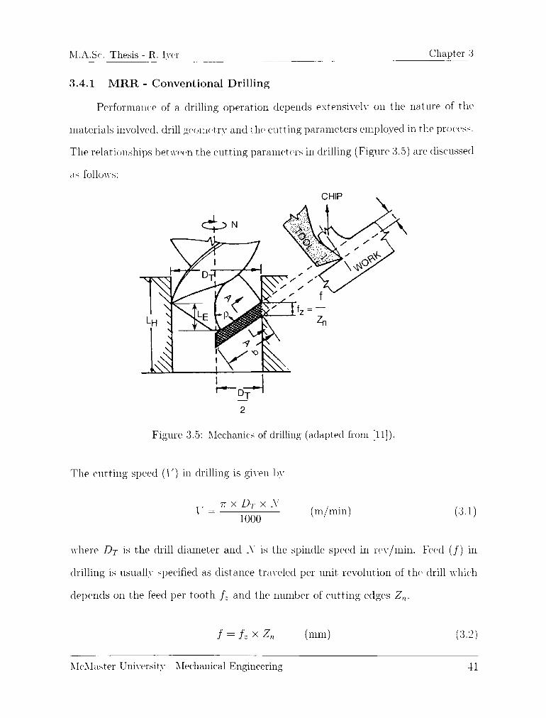
M.A.Sc. Thesis - R. Iyer Chapter 3
3.4.1 MRR - Conventional Drilling
Performanee of a drilling operation depends extensively on the nature of the
materials involved, drill geometry and the cutting parameters employed in the process.
The relationships between the cutting parameters in drilling (Figure 3.5) are discussed
as follenvs:
Figure 3.5: Mechanics of drilling (adapted from [11]).
The cutting speed (U) in drilling is given by
7T x DT x ArV = (m/min) (3.1)
1000VI) \ )
where Dt is the drill diameter and A' is the spindle speed in rev/min. Feed (/) in
drilling is usually specified as distance traveled per unit revolution of the1 drill which
depends on the feed per tooth /, and the number of cutting edges Zn.
/ = /= x Zn (mm) (3.2)
McMaster University Mechanical Engineering 41

M.A.Sc- Thesis R.Iyer Chapter 3
The feed rate (I j) in drilling is given by
Vf = fz x Z x X = f x X (mm/min) (3.3)
The material removal rate (MRR \CD) in conventional drilling is given by:
AIRH \CD =
"^(A)2**)(mm3/min) (3.4)
Drilling time T \cd is given by.
T \cd= -t 77 \r=
7~- mm) (3-5)/, x A x Zn \f
where, Lfj is the length of the hole and LE is twice the projection of the drill, required
to emgage the1 full diameter of the drill at the top and bottom of the hole.
3.4.2 MRR - Helical Milling
Although helical milling is emplcjyed to machine a hole, it follows the basic rules
of milling and like any other machining process, its performance is affected by the
cutting parameters aelopted. In helical milling since the tool rotates about its own
axis while simultaneously moving in the axial and radial directions, it is important to
specify the axial depth per 360 of circular tool travel (a0) as shown in Figure 3.6,
a0= n x (DH
-
DT) x t'&n{9R) (mm) (3.6)
where Dh is the diameter of the machined hole, Dt is the tool diameter and Or is
the ramping angle recommended by the tool manufacturer. The ramping length LR
per 360 of circular tool travel (Figure 3.6) can be calculated as:
Lr = \/(a0)'2 + [~ x (DH-
DT)Y (mm
McMaster University - Mechanical Engineering 12

M.A.Sc. Thesis R. Iyer Chapter 3
7T(DH-DT)
Figure 3.6: Tool travel in helical milling.
Substituting the value1 of a from ecmation 3.6, we get,
LR = v/[tt x (DH-
DT) x Um(9R)Y + [vr x (D-
DT)\<
TX X (DH~
DT) y/ttm(0R)2 + 1
Lr =
nx(DH-
DT)mm (3.8)
cos(t9H)
Since the tool traverses a helical path, the total length of tool travel (LT) is much
greater than the length of the hole (LH).
n x (DH-
DT) LHLT = x
cos(0fl) a0
ttx{Dh-
DT)
eos(9R)
LH cos{9R)
it x (DH-
DT) x sm{9i
ULH
s'm(9R)(mm) (3.9)
McMaster University- Mechanical Engineering 13

M.A.Sc. Thesis - R. Iyer Chapter 3
Hence from equation 3.9 it can be comprehended that for a given hole depth {LH).
the total length of tool travel (Lt) in helical milling is inversely proportional to sine
of the ramp angle [Or).
In the current experiments, ball nose end mills were employed wherein, quite
often the full diameter of the tool (Dt) is not engaged in the work. It can be seen
from Figure 3.7 that as the axial depth per 360 of circular tool travel (a0) is varied,
the effective cutting diameter (Deff) changes accordingly and in general is always
smaller than the tool diameter (Dt).
X
Rt
; Reff
Deff
Figure 3.7: Effective cutting diameter in ball nose end mills.
Considering triangle XVZ in figure 3.7, the effective cutting radius (Reff) of the ball
nose end mill is given by:
Reff2 = RT2 -
(RT ~ a0)2 = 2RT a0- a02
We know that 2 x RT = DT and 2 x Reff = Deff. where RT is the radius of the
tool and DFff is the effective cutting diameter of the ball nose end mill.
(RT-
ac
McMaster University Mechanical Engineering 44

M.A.Sc-. Thesis R. Iyer Chapter 3
Substituting, we getD,eff
a0(Dj
D,eff VaJDT-
<>c mm 3.10)
Hence the effective cutting speed (U;//) in helical milling is given by
\eff
IT X Deff X X
ioofj(m/min) (3.11)
In most CNC machines the feed rate reemired for programming a contour (cir
cular or helical) is calculated based on the center line of the tool. When the tool is
moved along a straight line, the feed rate along the center of the tool and the cutting
edge are identical. Howewor in case of helical milling since the tool moves along a
circle, there is a difference in the feed rate between the tool center and periphery
(Figure 3.8) and is accounted for as follows:
Figigure 3.8: Effective feed rate in helical milling.
McMaster University Mechanical Engineering 45

M.A.Sc. Thesis - R. Iyer Chapter 3
For a circular tool path, machining time (T) will be given as.
Length of travelT =
Feed rate
TT X DH
fz x Z x X
T = from equation 3.3 (min) (3.12)
Similarly in helical milling, machining time (T \hm) is given by.
Length of travel of tool center
Mac-hiniiig time (T #;M I
Circular feed rate at tool center
it x (DH-
DT) ..
.
(mm)
(3.13)
where 1 'jc is the feed rate at the center of the tool and can be computed from equations
3.12 and 3.13.
' 1}C = [{DH~
Dt)]*V) (mm/min) (3.11)
The radial engagement (ae). (Figure 3.8) is given by.
Total area to be removedaP =
Length of tool travel
x D2} x
n x (DH -
DT)'
"e=
1 x (D?- DT)(mm) (:i-15)
McMaster University- Mechanical Engineering 16

M.A.Sc. Thesis R. Iyer_
Chapter 3
Metal removal rate in helical milling (MRR \hm) is given by.
MRR \Hm =
a0 x af x \'fc (mm3/min) (3.16)
Hence from equations 3.9 and 3.13 the total time required in helical milling (T \hm)
to machine the hole is:
(T\hm) =
.. LT.0
(min) (3.17)\ fc x sin 9R
3.5 Process Strategy and Cutting Parameters
Down (climb) milling technique was followed in all helical milling experiments.
In helical milling, different bore to tool ratios (DH/DT) correspond to different ma
terial removal rates (MRR) despite constant cutting parameters, as reported by
Tonshoff et. al. [8] [9], during their investigation into the effect of Bore to Tool ratio
on hole quality.
Figure 3.9 indicates, two different, tool diameters used to machine the same hole
diameter by helical milling for bore to tool ratios (DH/DT) of 1.33 and 1.88. In a
givem situation where the spindle speed (X). ramp angle (9R). feed per tooth (/-)
and number of cutting edges on the tool (Z) are maintained constant for both the
instances, the material removal rate (MRR) is higher for higher bore to tool ratios.
The1 material removal rate (MRR) in helical milling (eq 3.16) depends upon the axial
depth per 360 of circular tool travel (a0), radial engagement (uF) and the circular
feed rate at tool center (l/c). Equations 3.6. 3.15 and 3.14 suggest that anv increase
in the bore to tool ratio (Dh/Dt) would increase the axial depth per 360 of circular
tool travel (a0) and circular feed rate at tool center (\'jc) while decreasing the radial
engagement (,.). The increase in the axial depth per orbit and feed rate at tool center
far outweigh the reduction in radial engagement thereby increasing the metal removal
McMaster University Mechanical Engineering 17

M.A.Sc-. Thesis - R. Iyer Chapter 3
rate (eq. 3.16). Higher metal removal rate results in higher machining forces, thus
increasing the deflection of the tool and influencing form and diametral deflation.
This is an important aspect to be considered in the selection of tool diameter in
helical milling.
Figure 3.9: Influence of Bore to Tool ratio, (a): DH/DT = 1.33, (b): DH/DT = 1.88
In order to evaluate the process strategy in conventional drilling, pilot drilling
trials we>re conducted considering three distinct scenarios.
"sp In the first scenario, trials conducted under dry conditions with no peck, resulted
in poor performance with catastrophic failure of the cutting edges.
"^ The application of cutting fluid through the coolant holes in the drill body with
no peck was attempted next. The cutting fluid assisted in the removal of chips.
but did not significant ly improve drill performance.
"S^ Finally peck drilling combined with the application of cutting fluid was em-
ployed resulting in the best performance, and hence was adopted for all the
McMaster University- Mechanical Engineering 48

lVL_A.Sc. Thesis R. Iyer Chapter 3
drilling experiments. The peck depth was chosen so as to ensure that the full
diameter of the drill was engaged during each peck cycle.
3.5.1 Cutting Parameters
In order to minimize the impact of tool overhang on tool life and the occurrence
of chatter [5], short series drills were chosen and tool overhang was restricted to
48 mm for all the tools testeM. The cutting parameters for drilling was based on the1
generic recommendations of the manufacturers, as specified in Table 3.5,
Cutting Speed (U) 30 m/min
Spindle Speed (X) 600 rpm
Feed per Tooth (/,) 0.06 mm/edge
Number of Cutting Edges (Zn) 2
Feed Rate (Y}) 72 mm/min
Drilling Method Peck Drilling
Peck depth 3 mm
Table 3.5: Drilling parameters.
Since the cutting speed (V) has the maximum influence on tool wear [12], the
same was maintained for helical milling. The feed per tooth however was increased in
helical milling from that in drilling based on the recommendations of the cutting tool
manufacturer. The cutting parameters employed to test the performance of helical
milling is listed in Table 3.6. It should be noted that the choice of ramp angles depends
upon the design of the cutting tool and is usually based on the recommendation of
the tool manufacturer.
McMaster University - Mechanical Engineering 49

M.A.Sc. Thesis - R. Iyer Chapter 3
Ball Nose End Mill Flat End mill
Cutting Speed (V) 30. 37. 17 m/min 06^ m/min
Ramp Angle^ (9R) 3jO
Axial Depth'' ((<(,) 0.659 mm 0.659 mm
Effective Diameter (Dejj) 5.47 mm 12 mm
Spindle Speed (X) 1740. 2160, 2760 rpm 1740 rpm
Feed per Tooth (fz) 0.10 mm/tooth 0.033 nun/tooth
Number of Cutting Edges (Zn) 2 6
Linear Feed Rate (l)) 348. 432. 552 mm/min 348 mm/min
Feed Rate at Tool Cent<T (l/c) 87. 108, 138 mm/min 87 mm/min
D : Parameter considered at the Et
<0> : Parameter considered per Kid"
'cctive Diameter (Dejf)of circular tool travel
Table 3.0: Helical milling parameters.
Center cutting end mills are preferred in order to take advantage of higher
ramp angles which translates in shorter machining times (equation 3.11). Also in
case's where blind holes are required, use of non center cutting end mills would leave
a small undesirable protrusion near the center of the hole.
3.5.2 Test Conditions and Force Measurement
Arai [4] and Kishawy [29] deduced through numerical simulation and experi
mentation that the temperatures in machining of hardened steel range from 700 C
to 1000 C. depending upon the cutting parameters employed. Research into drilling
of hardened steels has shown that for drilling depths over 10 mm. application of cut
ting fluid is essential to cool the tool and to flush the chips away [1] [5] [43]. This
was reinforced by the results obtained during pilot drilling trials that necessitated the
McMaster University Mechanical Engineering 50

M.A.Sc. Thesis R. Iyer Chapter 3
need for employing a cutting fluid (water soluble oil, lO'/e by volume) at a pressure
of 7 bar (0.7 MPa) through the coolant ducts in the drill body.
In view of the high temperatures involved, pilot helical milling experiments
were also conducted with a cutting fluid (water soluble oil, 10(/c by volume), supplied
externally, at a pressure of 7 bar (0.7 MPa). This however resulted in severe tool
chipping, attributable to thermal eye-ling [12]. Hence helical milling trials involved
just an air blow at a pressure of 8.3 bar (0.83 MPa), so as to cool the cutting edge
and blow the cliips away from the cutting zone.
The end of tool life for helical milling was characterized by a flank wear (\'b)
criterion of 300 //.m. Upon reaching the wear criterion, the tools were examined under
an optical microscope for chipping on the flank and rake1 face's, notch wear and the
flank wear (Vb) land width was measured. In the case of conventional drilling a
screech criterion, which occurred prior to catastrophic failure, was used to determine
the end of the trial and wear morphology was investigated [5],
The helical milling inserts obtained from the manufacturer were coated with
TiCN + TiN (Table 3.3) and in order to establish correspondence with the drilling tool
coatings, uncoated inserts were applied with BALINIT!JJJ FUTURA (TiAIN) coating
from an external source other than the tool manufacturer. Their performance was
evaluated not only in comparison to conventional drilling but also to that obtained
by helical milling with TiCN + TiN coating. Considering that four different types
of drills were tested, no attempt was made to repeat the tests. However, helical
milling trials were replicated to assess the performance consistency in terms of tool
performance and wear progression.
In order to facilitate measurement of torque and cutting force components, a
Kistler quartz three-component dynamometer (model 9255B) was used. The holes
machined using helical milling were sectioned for measurement and analysis of surface
McMaster University Mechanical Engineering 51

M_A.Sc. Thesis- R. Iyer Chapter 3
finish using the Zvgo Newview 5000. a non-contact surface testing machine. Prior to
characterization of surface finish, measurement of hole quality characteristic's, namely
roundness and hole tolerance were undertaken on the Zeiss Prismo 900 co-ordinate
measuring machine.
3.6 Chapter Synopsis
The current chapter details experimental set-up and cutting parameters em
ployed to test the benefits envisaged in helical milling of hardened AISI D2 tool steel.
In case of conventional drilling, the recommendations of four highly reputed cut
ting tool manufacturers was considered while selecting drill geometry anel machining
parameters.
As pointed out earlier, apart from the point angle (2p), none of the other geo
metric attributes of the drills we're similar, which were considered to be state of the
art for hard drilling. Helical milling tools consisted of a indexable ball nose end mill
and a solid carbide end mill, that are commonly used in the die and mold industry
and were smaller in size than the drills.
Since cutting speed is known to have the maximum impact on tool life, the same
was maintained for helical milling, whereas other parameters such as ramp angle (9R),
feed per tooth (f:) were based on the recommendations of the tool manufacturer.
Helical milling trails were performed dry with pressurized air supplied externally.
while drilling experiments were conducted wet with cutting fluid supplied through
the coolant holes of the drill.
In order to prevent slippage of the tools owing to high thrust forces associated
with machining of hardened steels and to restrict radial runout, a high precision power
chuck was used to hold the tools.
McMaster University Mechanical Engineering 52

M.A.Sc. Thesis R. Iyer Chapter 3
The experimental set-up. metal removal calculations and process strategy elis-
cussed in this chapter are critical for this research since they govern the reliability of
the results. Since two completely different machining process are compared in this
research, utmost care has been taken to ensure that the elements of variability are
reduced to the minimum.
McMaster University - Mechanical Engineering 53

M.A.Sc Thesis R. Iyer Chapter 4
CHAPTER 4
RESULTS AND DISCUSSION
4.1 Introduction
The difficulty- in drilling of hardened AISI D2 steel is due to the hard and abra
sive microstructure1 of the work material leading to catastrophic tool failure resulting
in poor tool life. The information presented in this chapter consists of validation of
the process of helical milling for hole making in hardened AISI D2 steel. Cutting
tests were conducted to compare drilling and helical milling in terms of attainable
tool life, cutting forces, tool wear characteristics and hole quality. Based on the drill
geometry, a hypothesis for the failure of drilling tools is put forth and verified. The
impact of tooling configuration (indexable versus solid carbide) on the hole quality
achieved in helical milling is also addressed.
McMaster University Mechanical Engineering 51

M.A.Sc Thesis - R. Iyer Chapter 4
4.2 Drilling of Hardened AISI D2
In the first phase of experimental work, drilling trials were undertaken em
ploying cutting parameters described in Table 3.5. Experimental trials conclusively
established the ineffectiveness of conventional drilling of hardened AISI D2 tool steel.
The drilling process was characterized by a loud shriek from the time of drill en
gagement with the workpiece signifying imminent tool failure, which increased as the
drill progressed into the hole. Even in the event that a single hole was convention
ally drilled, tool life variation in terms of the length of hole drilled was as high as
35'/. that can primarily be attributed to the geometrical characteristics (helix angle1,
point angle1, web thickness, shape of the cutting lip) of the drill affecting its cutting
mechanics and is discussed in this chapter.
4.2.1 Wear Modes in Conventional Drilling
The wear pattern of drilling tools 1 and 1 (Figures 4.1. 4.2) indicates catas
trophic fracture1 of the cutting edges at the periphery. The point geometry of tool 1
is similar to that of a Four-Facet Chisel Edge design formed by the intersection of the
primary and secondary relief planes ensuring reduction in thrust forces and improve
ment in centering accuracy. Tool 4 was ground to a modified split point geometry
with "S" shaped cutting edges and web thinning for enhanced performance [11].
The tools (1 and 4) have the same web thickness of 0.28 mm (Table 3.2) and
their respective cutting edge geometries advocate a positive cutting action with the
rake angle equal to the helix angle of the drill at the periphery. High normal rake
angles (an) and clearance angles (9) (Table 3.2) at the periphery of the drills reduces
their respective wedge angles () leaving the cutting edges vulnerable to failure due
to reduced edge strength and is observed in the wear pattern of these drills (Figures
1.1. 4.2).
McMaster University Mechanical Engineering 55

M.A.Sc. Thesis - R. Iyer Chapter 4
Catastrophic edge failure
Secondary relief
plane
Chipping of
chisel edge"
Catastrophic edge failurePrimary relief plane
Figure 4.1: Drill wear mode Tool 1.
Catastrophic
edge failure
Figure 4.2: Drill wear mode Tool 4.
McMaster University - Mechanical Engineering 56

M.A.Sc. Thesis - R. Iyer Chapter 4
The failure of the cutting edges is attributed to extremely high cutting forces gener
ated due to the presence of carbide particles in the workpiece microstructure impeding
dislocation mobility thereby increasing the flow strength of the material coupled with
poor cutting edge strength. Although drilling depths of 11.8 mm anel 6.5 mm respec
tively were attained with these tools, the wear pattern realized is highly undesirable
anel hence these tools are unsuitable for drilling of hardened D2 tool steels.
Tool 2 underwent complete disintegration after drilling a depth of approximately
11 min. with the fracture surface inclined roughly 15 to the drill axis indicating failure
in torsion (Figure 4.3). The spiral point geometry ('"S" shape chisel edge) of the drill
(Figure1 3.1) increases the web thickness of the tool as compared to conventional
twist drills. Any increase in web thickness has a direct influence on the thrust forces
generated in drilling and would be speculated as the cause of failure of the tool [3].
However the spiral point geometry- of the chisel edge of Tool 2. provides a lower
negative normal rake angle (on) than that of a conventional (straight) chisel edge
promoting cutting rather than extrusion at the drill center. Due to the cutting action
near the drill center, thrust forces are lower, which also translates into reduced burr
formation at hole exit and hence improving hole quality [11].
It is hypothesized that the hard and abrasive nature of work material coupled
with insufficient cutting edge strength due to reduced wedge angle ( ~ 58) cause
chipping or fracture of the cutting edges. In addition, the concave cutting edge
exacerbates the problem by providing a sharp corner that is susceptible to chipping
[44], increasing the cutting forces. As a result, the torque acting at a given radial
location in drilling, defined as the sum of the cutting forces multiplied by its distance
from the drill center increases causing failure across the plane of maximum normal
stress. The carbide tool substrate material being brittle in nature, is weaker in tension
than in shear with the plane of maximum tension occurring along surfaces at 45" to the
McMaster University - Mechanical Engineering 57

M.A.Sc-. Thesis R. Iyer Chapter 4
shaft axis causing catastrophic failure of the tool. Although Tool 4 sported a concave
cutting edge as Tool 2 (Figure 3.1), it provided a stronger wedge angle ( ~ 75") that
prevented such a catastrophic failure.
Figure 4.3: Drill wear mode - Tool 2.
The best outcome among the four drills tested, corresponded to tool 3 (Figure
4.1) that yielded just a single hole, but incurred rake face wear in excess of 300 p.m.
Modified Split Point configuration with an "S" shaped cutting edge geometry similar
to tool 4 was ground on the drill, but demonstrated a higher web thickness (Table 3.2)
as compared to tools 1 and 4. The increased web thickness is due to adoption of notch
type web thinning procedure which produces two small cutting edges on each side
of the chisel edge, improving edge security and reducing thrust forces. Observation
of the drill periphery indicated micro-chipping of the cutting edges in line with the
results obtained for tools 1 and 1 albeit not as severe as in the previous cases. The
improved performance of tool 3 is attributed to the cutting edge correction in the form
of edge honing provided at periphery and the application of tougher (K10) carbide
grade which improves toughness by 50 CO'/C preventing premature failure [36]. The
increased toughness helps in resisting fracture caused by high mechanical loads, but
comes at the expense of hardness of the tool, affecting its wear resistance. The rake
face wear of the cutting edges exceeded the wear criterion of 300 pm restricting the
application of this tool for drilling of hardened D2 tool steel.
McMaster University Mechanical Engineering 58

M.A.Sc. Thesis - R. Iyer Chapter 4
Flank wear
(VB) > 300 pm
Failure at
tool center
Flank wear
(VB) > 300 pm
Figure 4.4: Drill wear mode - Tool 3.
It can be seen that none of the drills tested followed the desired wear pattern of
a conventional drill (Figure 4.5). The wear profiles experienced in case of conventional
drilling of hardened D2 tool steel indicate1 catastrophic fracture1 caused due to excessive
mechanical loads acting along the cutting edges. The location of the fracture is
consistently observed to be along the periphery on the flute face (except for tool 2
that disintegrated completely) and is discussed in the following section.
Figure 1.5: Conventional twist drill wear pattern (adapted from [34]).
McMaster University Mechanical Engineering 59

M.A.Sc. Thesis R. Iyer Chapter 4
4.2.2 Twist Drill Geometry
With a view to understanding chipping of the cutting lips of the drill (Figure
4.1. 4.2. 4.4), a detailed understanding of the mechanics of drilling is necessary. In
contrast to other metal cutting processes, the rake face of a twist drill is not flat,
but twisted with increasing rake angle (a) from the center tenvards the periphery
producing a rotating chip (Figure 1.6). Cutting velocities also vary along the cutting
eelge, which combined with a larger peripheral rake cause strong side curling of the
chip. This strongly side curled chip, shown by a dotted line in the figure 4.6. is further
forced to curl when it encounters obstruction in the form of drill web anel the wall of
the hole as it progresses into the workpiece1 forming a conical helical chip. The chip is
subjected to angular velocities uj,., ujr anel ^jz along the drill axis and along the A' and
Z directions respectively (Figure 4.6). The resultant of these three velocity identities
imparts helical motion to the chip at an angular velocity of uj [45].
Figure 4.6: Conical helical chip produced by twist drill [45].
Chip formation in drilling occurs by extrusion / indentation around the chisel
edge, and cutting along the lips of the drill. The inherent geometry of the cutting
edges of the drill cause a variation in the helix angle (5), the clearance angle (9) and
McMaster University Mechanical Engineering 60

M.A.Sc. Thesis - R. Iyer Chapter 4
the wedge angle () along the drill lip. The normal rake angle () at any radial
loc-atiom (r) along the cutting edge of the drill is given by the relationship [46] [47]:
tamotan(c5)
sin(p)[cos(J) + sin(.^)tan(J)cos(p)2] -
[tan(.J)cos(p)] (4.1)
where p is half point angle of the drill; c5 is the helix angle at radial location / and .i
is the web angle at the same radial location (r) under consideration.
Lond or_
morgin
Oiometer
Chisel edge
angle
Web
thickness
Web Angle (/? )
Depth of body clearance
Figure 4.7: "Web angle (J) of a drill (adapted from [48]).
The web angle (3) varies along the cutting edge (Figure 4.7) and is expressed
as [12] [46] [47]:w
(4.2)sin(.i) =-
r
where r is the radial location along the cutting edge and w is half the web thickness
of the drill. The helix angle (<)) can be written as [12] [46] [47]:
tan(c5) =iixr
L(4.3)
where L is the lead of the helix and is constant for a given drill. Since this information
McMaster University Mechanical Engineering 61

M.A.Sc. Thesis R. Iyer Chapter 4
is usually not supplied by the drill manufacturer it can easily be computed as:
L =
2/iRt
tan(e50)(4.4)
where Rt is the radius of the drill and S0 is the helix angle at the periphery of the
drill.
Lip (or nominol) cleorance
angle at periphery
i
Outer corner
Helix ongle(or rake ongleat the periphery
Figure 4.8: Clearance angle (9) and Helix angle (<5) of a drill at the periphery [48].
It is apparent from equation 4.1. that the normal rake angle (a) will vary with
any variation in helix angle (S) and web angle () along the cutting edge. Similarly,
the clearance angle (9) also varies along the cutting edge and hence is always specified
at the periphery' of the drill. It can be computed using the expression [46] [47]:
tan(0)cos(/o)[cos(di) tan( J) (tan(.J0) tan((90) tan(p))]
cos(J0) + tan(/j)cos(p) [tan(,J0) tan((90) tan(p)](4.5)
where 0o is the clearance angle at the drill periphery and ij0 is the web angle at the
periphery of the drill, given by the relationship [12] [46] [47]:
sin ,j0RT
(4.6)
The wedge angle () defined as the angle between the rake face and clearance face of
McMaster University Mechanical Engineering 62

M.A.Sc. Thesis - R. Iyer Chapter 4
the tool can be computed as:
= 9O-an-0 (4.7)
Using the above relationships, variation in normal rake (an). clearance angle (9)
and wedge angle () for the drilling tools used in the current research were mapped
using MATLAB and is shown in Figure 4.9.
It can be seen that the normal rake angle (o) attains very high negative values
close to the chisel edge and gradually approaches a value equal to the helix angle
(S0) towards the periphery of the drill. The clearance angle (9) and wedge angle ()
however decrease from the chisel edge to the outer corner of the drill lip. The cutting
edge in drilling is formed by the intersection of the flute and flank faces and its shape
is strongly influenced by the point angle, helix angle and the flute contour. Galloway
[16] observed the shape of the cutting lip to vary from a convex shape at a point
angle (2p) of 60 to concave at 150. At a point angle (2p) of 118, a straight cutting
lip was obtained which facilitates maximum tool life. The flute contour and the helix
angle are on the other hand are designed so as to provide this straight cutting edge
for a point angle (2p) of 118 [11] [16] [48].
The drilling tools (Figure 3.1) used in this research have a point angle (2p) of
140 advocating a concave cutting edge for improved chip breaking except for tool
1 which sported a straight cutting edge [11] [44]. Even though the relationships
developed to study the variations in drill angles are based on a straight cutting edge.
Chayan et. al. [49] reported that they can very well be applied to concave and convex
cutting edge designs of the conventional twist drill. The effect of the variation on the
wedge angle (f ) (Figure 4.9) in terms of catastrophic tool failure is discussed in the
next section.
McMaster University Mechanical Engineering 03

M.A.Sc. Thesis - R. Iyer Chapter 4
~ 40 -
V 30 1
20"
o> 10 -
Tool 1
c^
.
ro 0 -
5 -10 :
JZ -20 :Tool 4
| -30 J
o -40 -
Tool 3
^en
" / Tool 2-50 -
1 1 1 1 1 1 1
0 1 2 3 4 5 6 7 8
Radius Location (mm)
60 -,
. Tool 2
s.50"
y-^ 40 -
Tool 3c
.
y: 30-
. \M Tools 1 & 4 \o \ X s
i 20-wg 10-
0 _
V^
1 l 1 1 1 1 1
() 1 2 3 4 5 6 7 13
Radius Location (mm)
t r
3 4 5
Radius Location (mm)
Figure 4.9: Variation of normal rake angle (an). clearance angle (9) and wedge angle
along the cutting edge of the drills tested.
McMaster University Mechanical Engineering 64

M.A.Sc. Thesis - R. Iyer Chapter 4
4.2.3 Influence of Work Material
While investigating the flow stress of hardened AISI D2 using the Compressive
Split Hopkinson Bar technique (CSHB). Becze et. al. [50] observed the material to
undergo significant strain hardening at low (3.5 x 1()3 s_1) and high (5 x 10⁴ s~l)
strain rates owing to carbide particles (Section 2.3.2) in the steel impeding mobility
of dislocations. Temperature had a marginal effect on the shear flow stress of the
material which was measured to be in excess of 1300 MPa at an ambient temperature
and approximately 1100 MPa at 500 C. Although benign from the point of view
of augmenting the wear resistance of the material, the carbide particles significantly
hinder machinability by increasing its flow strength and inducing abrasive wear.
The increased flow strength of the material necessitates the use of a stronger
cutting edge. The intrinsic variation of the normal rake angle (ev) in drilling from
being highly negative (typically about 23", Figure 4.9) near the drill center to being
positive at the drill periphery corresponds to lower wedge1 angles ( ~ 15" to 70
Figure1 1.9) of the cutting edges at the periphery, weakening the overall strength of
the cutting edge. Consequently, this is also the location of failure (Figures 4.1, 4.2.
4.4) in most of the drills tested. Although a positive rake (an) is obliging in terms
of reducing the cutting forces and temperatures, it compromises the strength of the
cutting edge (Figure 4.10) which is paramount in this application.
I
/ I / To_o1 \,
Work piece ?
Figure 4.10: Wedge angle () at radial location r (r Drill periphery).
McMaster University Mechanical Engineering 65

M.A.Sc, Thesis - R, Iyer Chapter 4
Chipping of the cutting edges at the drill periphery (Figures 4.1, 4.2. 4.4) has
further been investigated in light of the stresses developed along the cutting edges.
The stresses developed along the cutting edge while machining hardened AISI D2 and
AISI H13 tool steels was studied by Xg [51] using finite element analysis. Simulations
were performed for a normal rake angle (an) of 35. which is equivalent to the helix
angle at the periphery (50) for tool 1 (Table 3.2). Clearance angle at the periphery
(90) corresponded to 10 giving a wedge angle () of 15" and cutting speed (V) was
maintained at 30 m/min for an uncut chip thickness of 0.06 mm. Using Arbitrary La-
grangian Eulerian formulation and Johnson-Cook constitutive model to characterize
the non-linear thermo-plastic work material behavior, the finite element simulation
indicated the highest maximum tensile principal stresses for a tool with no flank wear
to be on the order of 2 GPa (Figure 4.11).
Maximum Principal Stress (GPa)
Figure 4.11: Stress field when machining : (a) D2 and (b) H13 tool steels [51].
The transverse rupture strength (TRS) of commercially available fine grain car
bide varies in the range of 1.5- 2.5 GPa at ambient temperature [52]. Due to abrasive
nature of the material, tool wear progresses rapidly increasing the maximum stresses
on the tool. Arai at. al. [4] showed the temperature to approach 700 "C while drilling
McMaster University Mechanical Engineering 66

M.A.Sc. Thesis R. Iyer Chapter 4
D2 at a hardness of 520 HV (~ 51 HRC) and is envisioned to be higher in the current
research, as higher hardness of the work material and cutting speeds are employed.
The increase in temperature, would further decrease the TRS of the cutting tool
elucidating chipping of the cutting edges. The TRS of submicron grade cemented
carbides can be as high as 3.5 GPa [52], however, the higher end of the TRS spec
trum generally corresponds to a lower hardness that compromises its wear resistance,
which is unfavorable in reference to the abrasive carbides in D2 that are of hardness
2400 HV, which is three times that of martensite. It can be seen from Figure 4.11
that the maximum stress developed while machining AISI H13 is only half of that
of AISI D2, which explains why drilling of hardened AISI H13 does not involve any
of the problems associated with D2 [5]. The stress analysis emphasizes the need for
negative rake (o) tools corresponding to sufficient wedge angles () when machining
hardened AISI D2 tool steel.
Additional problems in drilling arises from the drop in the cutting speed (V) to
zero at the drill center leading to material removal by extrusion rather than cutting.
The chisel edge configurations influence the thrust forces, rigidity of the drill and
its centering capabilities. Although, all the tools tested incorporated modern point
configurations designed to reduce the problems associated with the chisel edge, tools
1, 3 and 1 show chipping at the tool center (Figures 1.1, 4.2. 4.4 ). The hardness
of the work material combined with an abrasive microstructure further exacerbates
the problem. Difficulties with drilling of hardened steel can be comprehended with
reference to the works of Konig et. al. [33] and Coldwell et. al. [5], who reported drill
life to vary by a factor of over 30 and 7 respectively depending upon the work material
microstructure.
McMaster University - Mechanical Engineering 67

M.A.Sc. Thesis - R. Iyer Chapter 4
4.2.4 Possible Drill Geometry Modifications
The stress analysis presented in the previous section pointed to the preferred
need for negative rake (a) tools that correspond to sufficient wedge angles () to
provide the necessary strength to the cutting edge when machining hardened D2 tool
steel. It is seen from equation 4.1 that of all the geometrical parameters of the drill.
the helix angle (c5) and the point angle (2p) would have the most influence on the
normal rake angle (n) along the cutting edge of the drill. This section examines the
possibility of rendering the drill geometry to correspond to adequate wedge angle (E).
The simulation results for variation in helix angles at the periphery (<)) of the
drill and variation in point angles (2p) is shown in Figures 1.12 and 1.13 respectively.
It can be seen from Figure 4.12 that as the peripheral helix angle (S0) is changed
from 28 to 0.1, the variation in normal rake angle (o) from the drill center to
its periphery tends to be less acute. In fact at a peripheral helix (S0) of 0.1, the
normal rake (an) is negative all along the cutting edge with minimal variation in the
wedge angle (). The variation of clearance angle (9) along the cutting edge of the
drill (1.12) depends upon the point angle (9) and the web angle (J) as reported in
Eeiuation 1.5 and remains unaffected by variations in the peripheral helix angle (S0).
Variation in the point angles (2p) are seen to have a marginal effect on the
normal rake angle (cv) and the clearance angle (9) as seen from Figure 1.13. At
a point angle (2p) of 179, there is almost no variation in the normal rake (nn) or
clearance angle (9) and the drill resembles a center cutting end mill, providing a
stronger wedge angle (). This would however lead to a highly concave cutting edge
shape, which is prone to chipping at the periphery of the drill [16] [44], Moreover,
thrust forces are minimum at a point angle (2p) of 118 and increase parabolically
with further increments in point angle (2/)) [11] resulting in work material breakouts
at hole exit leading to poor part quality.
McMaster University Mechanical Engineering 68

M.A.Sc. Thesis R. Iyer Chapter 4
Web thickness (2w) : 0.78mm, Tool Diameter (d) : 16.0mm
Point Angle (2p) : 140, Clearance Angle at Periphery (90 ) : 9
t ' i i ' i r
3 4 5 6 7
Radius location (mm)
t ' i ' r
3 4 5
Radius location (mm)
i ' i ' i ' r
3 4 5 6
Radius location (mm)
Figure 4.12: Variation in normal rake angle (a ). clearance angle (9) and wedge angle ()along the cutting edge with variation in peripheral helix angles (S0).
McMaster University Mechanical Engineering 69

M.A.Sc. Thesis - R. Iyer Chapter 4
Web thickness (2w) : 0.78mm, Tool Diameter (d) : 16.0mm
Helix Angle at peripehry (80) : 0.1 , Clearance Angle at Periphery (0) : 9
0-
a"
ef -10 -
Normalrake
angle
O
O
Of//\ > 2p = 179
l//\ ^> 2p = 140
If* > 2p = 118
/ >2p = 80
-50 -
i | i | i | i | i | i | i | i
3 4 5 6
Radius location (mm)
50 -
5, 40 -
? 30-CO
<D
V2p = 80
2p = 118
2p = 140
20-k_
CO
a>
O 10-
y2p = 179
0-' 1 I I ' I ' 1 ' 1 ' 1 '
3 4 5 6
Radius location (mm)
86.25 -
85.50 -
84.75 1
84.00 -
83.25 -1
0
c
(0
5 82.50 _|
| 81.75-
81.00 1
80.25 1
0
X2p = 80
2p =
/118
2p = 140
2p = 179
~\ \ i \ ' \ r2 3 4 5 6 7
Radius location (mm)
Figure 4.13: Variation in normal rake angle (n), clearance angle (9) and wedge angle ()
along the cutting edge with variation in point angles (2p).
McMaster University - Mechanical Engineering 70

M.A.Sc. Thesis R. Iyer Chapter 4
A reduction in helix angle at the periphery of the drill (80) not only has the
most pronounced effect in terms of achieving a suitable rake angle (cvn) variation
throughout the cutting edge length, but also affects the rigidity and chip evacuation
capability of the drill. The maximum cutting force that a drill can withstand depends
upon its torsional stiffness, which in turn depends upon the cross sectional area and
the geometric form of the drill, influenced by the helix angle [53]. Narasimha et. al.
[17] observed the torsional stiffness of the drill to vary parabolically with the helix
angle (c50) and reach a maximum value at 28" (Figure 4.14). Lower helix angles
also increase the thrust forces in drilling increasing the chances of edge breakouts at
hole exit. Furthermore, a negative" rake would tend to push the chips into the hole,
causing build up and hence affecting chip ejection. Although using a smaller (0.1)
helix angle (S0) increases the edge security of the drill, it affects its torsional stiffness
and chip evacuation capabilities thereby seriously affecting its applicability in drilling
of hardened steels.
5000
4000-
o
2
= 3000 -
J3
C/J
w
O
2000-
1000-
d 3/8Kt
1/4Kt
a 13/32Kt
HELIX ANGLE deg
Figure 1.11: Effect of helix angle on the torsional stiffness of the drill [17]
McMaster University Mechanical Engineering 71

M.A.Sc. Thesis R. Iyer Chapter 4
In light of the geometry inherent to drills, it can be seen that it is infeasible
to supplement the wedge angle () along the cutting edge of drill by provision of
a continuously negative rake angle (an). It was shown that any variation in the
geometrical parameters seriously affects the design of the drills. Since the design of
drills is essentially a compromise between, overall tool stiffness, chip evacuation and
cutting efficiency, it can be concluded that a completely negative rake (an) cannot be
incorporated rendering it impossible to drill hardened AISI D2 tool steel. Although
drilling of hardened D2 tool steels is currently not possible, it can successfully be
milled [7] indicating the possibility of employing helical milling for machining holes
in hardened AISI D2 steel.
4.3 Helical Milling of Hardened AISI D2
In stark contrast to conventional drilling that was characterized by a loud squeal
accompanied by catastrophic tool failure which yielded just a single hole at best, the
number of holes that could be machined in helical milling with TiCN + TiN coating
was 10 holes (Figure 1.15).
Helical
Milling
Drilling
Figure 4.15: Tool life obtained in conventional drilling and helical milling
McMaster University - Mechanical Engineering

M.A.Sc. Thesis R. Iyer Chapter 4
The influence of tool coating on the performance outcome in helical milling
is presented in Figure 4.16. Since TiAIN inserts were not available as a part of
the standard product program, uncoated inserts were coated with a TiAIN coating
from an external source other than the tool manufacturer. Despite possessing better
tribological properties than TiCN and TiN coatings, poor tool life was obtained with
TiAIN coating at an effective cutting speed (\'e/f) of 30 m/min. Visual inspection
of the inserts show spading of the coating on the rake face1 exposing the substrate1
carbide surface (Figure 1.21) limiting their tool life. The performance of TiAIN
coatings improved with increase in effective cutting speeds (\'e/f) as seen in Figure
4.16.
18
^ 16-
l! 14-o
o12-
% 1<Ho
X
0
.Q
E7J
8-
6-
4-
2-
0
TiCN +TiN
[^ TiAIN
i30 37 47
Effective Cutting Speed (m/min)
Figure 4.16: Influence of coating on tool life in helical milling.
While evaluating the hot-hardness of titanium nitride (TiN), titanium carbo ni
tride (TiCN) and titanium aluminum nitride (TiAIN) coatings from 25 C to 1000 C.
Jindal et. al. [54] illustrated that TiCN has the highest room temperature hardness
which gradually deteriorated with an increase in temperature (Figure 4.17). The
maximum service temperature of TiCN coating is restricted to 400 "C as compared
McMaster University Mechanical Engineering 73

M.A.Sc. Thesis - R. Iyer Chapter 4
to 900 C for TiAIN coatings [38], implying that the latter can withstand higher cut
ting temperature environments with minimal detriment to its properties. Moreover
at elevated temperatures, a thin layer of aluminum oxide (AI2O3) is formed on the
tool surface preventing tribo-oxidation of the coating, thus reducing tool wear and
improving tool life [55], However with an increase in effective cutting" speeds (Up//),
the increasing cutting temperatures depreciate the hardness of TiCN coating and
degrade their performance.
3000
200 400 600
Temperature [C]
800 1000
Figure 4.17: Coating micro-hardness (HV) as a function of temperature [54].
Replication of machining trials involving TiCN + TiN coated inserts revealed
performance variation of 10'A in helical milling (Figure 4.15). Trials with TiAIN
inserts were however inconsistent owing to coating peel off and is attributed to the
coating process. As temperature increases, the differences in thermal expansion co
efficient between the coating and the tool substrate give rise to large thermoelastic
stresses in the coating causing it to peel off exposing the substrate [11]. It is inter
esting to note that the location of the coating peel off is at the point of maximum
cutting speed entailing the highest temperature along the cutting edge.
McMaster University - Mechanical Engineering 74

M.A.Sc. Thesis - R. Iyer Chapter 4
The results obtained in the current research is compared to that obtained by
Konig et. al. [1] [33] in Figure 4.18. Since there is a large variation in the cutting
parameters and tool configurations, a more generic methodology of comparison in
terms of the volume of metal removed is adopted. Coldwell et. al [5] employed a
cutting speed of 5 10 m/min with a feed (/) of 0.05 0.08 mm/rev and achieved a
volumetric tool life of approximately 6 cm3. Although the flank wear (\'b) measured
was only 0.1 mm, the cutting edges showed micro-chipping and hence were withdrawn
from further use. Konig et. al. [1] [33], developed an indexable drilling tool (diameter
= 34 mm) incorporating negative rake (n) PCBN inserts to machine holes in hard
ened X210Cr\V12 (DIN equivalent of AISI D2) steel. Although an exceptional tool
life of 500 mm was achieved for a blind hole depth of 31 mm, the negative1 rake (n)
susceptible to hole exit failures restricted its application. Furthermore, Konig et. al.
[1] [33] and Coldwell et. al. [5] employed cutting fluid to flush the chip away from
the cutting area and also to provide cooling to the cutting edge. Pressurized air was
employed in case of helical milling which translates into additional savings in terms
of elimination of fluid disposal and protecting the environment.
1500
o, 1250-
"a
1000-
E
TO
%Ek4
o
in
E_go
>
750
500-
250-
0
Helical Milling (TiCN + TiN)
I I Helical Milling (TiAIN)
R^^l Conventional Drilling (CBN)
-P-1
75
t
150 225 300
Cutting Speed (m/min)
375
Figure 4.18: Tool life comparison with respect to previous research work.
McMaster University Mechanical Engineering

M.A.Sc. Thesis - R. Iyer Chapter 4
4.3.1 Wear Modes in Helical Milling
Unlike drilling, wherein the predominant wear mode was catastrophic fracture of
the cutting edge, helical milling displayed a progressive wear pattern. The governing
wear mechanisms as a result of the mechanical and thermal load acting on the cutting
edge during helical milling of hardened D2 tool steel, are discussed below:
"Sf Abrasion Wear . This type of wear is caused by the hard particles in the work-
piece material. Abrasive wear is usually controlled by increasing the hardness of
the tool material. Flank wear, notch wear on the leading edge and nose1 radius
wear are typical examples of abrasive wear and is desirable since it progresses
uniformly [12] [56].
Attrition Wear : This type of wear occurs at relatively low cutting parameters
formed by the built up edge (BUE) formed along the cutting edge of the tool.
Under intermittent cutting conditions (like milling), BUE is formed between the
chip and the cutting edge, with successive layers from the chip being welded and
hardened becoming part of the cutting edge. Upon subsequent engagement, the
strongly bonded work / tool material is torn away from the tool surface and is
characterized by a rough anel uneven plucked surface on the tool rake face [56]
[57]. This form of wear mechanism is called attrition and is primarily adhesive
in nature.
Depending upon the cutting conditions and workpiece microstructure, either
one or a combination of the factors listed above is responsible for tool wear. In case
of hardened D2 tool steel, wear is influenced by the conspicuous presence of hard
(2100 HV) (Fe. C'CrC? carbides of particle size 5-25 //m that are embedded in the
martensite matrix [30], The wear progression of TiCN + TiN coated indexable ball
McMaster University Mechanical Engineering 76

M.A.Sc. Thesis R. Iyer Chapter 4
nose end mill at a effective cutting speed (Vcff) of 30 m/min and that of TiAIN in
serts at a cutting speeds (Ue//) of 30 m/min . 37 m/min and 47 m/min are as shown
in Figure 4.19. In stark contrast to conventional drilling where tool failure was catas
trophic macro fracture, helical milling displayed progressive flank wear arising clue
to abrasion and attrition wear comprising micro-cracks along the rake face (Figures
1.20, 4.21, 4.22. 4.23. 4.24. 4.25).
Although flank wear progressed uniformly in all these tests, trials with TiAIN
inserts at a effective cutting speed (Veff) of 30 m/min had to be terminated at a flank
wear (Vb) of 0.125 mm (central) and 0.119 mm (peripheral) due to flaking of coating
on the rake face. Observation of the rake face (Figure 4.21) indicates failure due to
spalling attributed to the problems in coating procedures. As the exposed surface
is more likely to fail catastrophic-ally, the trials were discontinued although the flank
wear criterion (\'b) of 300 //in was not reached.
The wear progression for TiCN + TiN inserts at effective cutting speeds (lre//)
of 37 m/min and 17 m/min were not plotted due to poor tool life obtained rendering
their application ineffective above 30 m/min effective cutting speed (K//)- The wear
mode (Figure 4.22 and 4.24) shows chipping along the rake face around the vicinity
of maximum cutting speed. TiCN has an maximum operating temperature of 400 C
above which it loses its properties [38] and as cutting speed increases, the temperature
generated along the cutting edge also increases causing failure of the coating and
exposing the carbide substrate along the rake face instigating wear. In both the cases.
the rake face wear supersedes the flank wear criterion restricting the performance of
these tools. TiAIN coated inserts on the other hand show no such defects at elevated
cutting speeds (Figure 1.23 and 1.25) and display uniform flank wear (Figure 1.19)
due to its inherent properties discussed in Section 4.3.
McMaster University - Mechanical Engineering 77

M.A.Sc. Thesis - R. Iyer Chapter 4
_
0.30 -|
| 0.25 -|
"i" 0.20
5 0.15-
ra 0.10 JUL
0.05-
0.00
0
Effective cutting speed ( Ve)= 30m/min
n=-n=n-n^n=
=n=n:^- TiCN (Central)
-D TiCN (Peripheral)
i 1 r
4 6 8
Number of holes drilled
T
10 12
Effective cutting speed ( Vg)= 30m/min
0.30-
0.25-
F .
E 0.20-
j_
(U 0.15 -
<1>
0.10-C .
to
LL0.05-
0.00-
TiAIN (Central)
? TiAIN (Peripheral)
Trials stopped due to spalling observed on .
the rake face of both inserts
i i r
2 3 4
Number of holes drilled
0.30
0.25-
0.20 -
0.15-
0.10-
0.05-
0.00.
Effective cutting speed ( l/)= 37m/min
o=o=o=oo^=0=c
,o,o=8=8-0^0=
TiAIN (Central)) TiAIN (Peripheral)
T
2
1
4
1 ' 1 ' 1 '
6 8 10
Number of holes drilled
12 14 16
0.30 -|
~0.25
E_ 0.20
s -15-i*
0.10-
r? 0.05 -
0.00.
Effective cutting speed ( Veff)= 47m/min
0,o-o-o-o-w
?
~\ i i r
6 8 10 12
Number of holes drilled
TiAIN (Central)
o TiAIN (Peripheral;
T"
14
T"
16 18
Figure 4.19: Flank wear progression in coated indexable insert ball end mills.
McMaster University - Mechanical Engineering 78

M.A.Sc. Thesis R. Iyer Chapter 4
Central Insert Peripheral Insert
Figure 4.20: Wear mode of TiCN coated inserts in helical milling at Vefj = 30m/min.
Central Insert Peripheral Insert
Figure 4.21: Wear mode of TiAIN coated inserts in helical milling at Y(.fj = 30m/min.
McMaster University Mechanical Engineering 79

M.A.Sc. Thesis - R. Iver Chapter 4
Central Insert Peripheral Insert
Figure 4.22: Wear mode of TiCN coated inserts in helical milling at Vefj = 37m/min.
Central Insert Peripheral Insert
Figure 4.23: Wear mode of TiAIN coated inserts in helical milling at Veff = 37m/min.
McMaster University Mechanical Engineering 80

M.A.Sc. Thesis - R. Iyer Chapter 4
Central Insert Peripheral Insert
Figure 4.24: Wear mode of TiCN coated inserts in helical milling at Vefj = 47m/min.
Central Insert Peripheral Insert
'
-'
.-'^^"H^l ^jj^;
-^^
\{Hnle!
^ -^J1Attrition wear
(Rake face)
* 2.0mrf
1 1
Attrition wear
(Rake face)-2.0nim 1
ifc"
Figure 4.25: Wear mode of TiAIN coated inserts in helical milling at Yf f f= 47m/min.
McMaster University - Mechanical Engineering 81

M.A.Sc. Thesis R. Iyer Chapter 4
Observation of wear modes in helical milling (Figures 4.20. 4.21, 4.22. 4.23.
4.24, 4.25) indicates a peculiar pattern inherent to ball nose end mills while machining
hardened tool steels [58] [39] [41]. Attrition wear in the form of micro chipping around
the vicinity where full diameter of the ball comes into contact with the workpiece
was observed to be the predominant wear mechanism in helical milling. The wear
morphology along the rake and flank faces in helical milling for TiCN + TiN coated
inserts at an effective cutting speed (Veff) of 30m/min is shown in figure 1.26.
i 200 um i
Figure 1.26: Wear morphology along the rake and flank faces in helical milling.
When machining at relatively low cutting speeds, low machining temperatures
facilitate formation of built up edge (BUE) along the cutting edge of the tool. BUE
is formed along the cutting edge in helical milling as it engages in the cut due to
welding of successive layers of chip material flowing past the rake face. The BUE
becomes a part of the cutting edge as it disengages the cut. During the next entry.
the localized tensile stresses imposed by the flowing work material over the BUE
elicits fragmentation of the cutting edge along the rake face exhibiting a very rough
surface [57] and can be observed from the wear morphology shown in Figure 4.26.
Attrition wear is not accelerated by higher cutting speeds and temperatures owing
McMaster University Mechanical Engineering 82

M.A.Sc. Thesis - R. Iyer Chapter 4
to lower BUE formation over the tool rake face, as observed by the wear pattern of
TiAIN inserts at higher cutting speeds (Figures 4.23, 4.25). On the other hand TiCN
rapidly oxidizes at higher cutting speeds due to rise in temperatures exposing the
substrate and thus limiting its tool life as explained previously.
4.3.2 Helical Milling Tool Geometry
The analysis of stresses acting along the cutting edge (Section 4.2.3) did impress
upon the need for negative rake angle (c,n) for strengthening the cutting edge when
machining hardened AISI D2 tool steel. It was reported in Sextion 4.2.4 that such a
provision is not possible to incorporate1 in conventional drills, but is possible in end
mills. Figure 1.27 shows an orientation similar to the helical milling tool, except for
the radial rake (q>), which is neutral (0) and in this case is depicted as negative.
The helical milling tool assembly provides a negative axial rake (na) of 10 and a
side1 clearance (9) of 9 (Table 3.3). Using equation 1.7, we can deduce the wedge
angle () to be 91.
Figure 1.27: Axial (aa) and radial (ar) rake in milling (adapted from [56]).
Unlike conventional drilling, the normal rake angle (an) does not vary in end
mills therein- facilitating a constant negative rake (a) along the entire cutting edge
imparting strength by providing a constant and higher wedge angle (). In addition
McMaster University Mechanical Engineering 83

M.A.Sc. Thesis R. Iyer Chapter 1
to higher wedge angle (). the orientation of the cutting edge (Figure 4.27), protects
the tool tip from the initial shock during engagement with the workpiece (Figure
4.28). It also changes the direction of the resultant force away from the cutting tip
and towards the body of the tool hence arresting chipping.
Figure 4.28: Wedge angle () in milling.
The negative rake (a) also reduces the cutting edge temperatures by providing
a larger area for heat conduction [29]. Although high negative rakes (e.n > 20)
would greatly supplement the cutting edge, they are not preferred due to nature
of forces generated during machining. At a normal rake angle (cvn) of 20, the
thrust force (Fq) is approximately twice the cutting force (Fp) demanding high tool
holding stiffness in order to avert chipping due to tool deflections [1], [59]. A larger
clearance angle (9) on the other hand would also weaken the cutting edge making it
susceptible to chipping. The optimum clearance angle (9) and radial rake angle (ar)
for solid carbide non-center cutting end mill designed to machine hardened (45 HRC)
AISI D2 are 14 each respectively [60]. The axial rake (c\) forms the governing
normal rake (a,,) for all face milling operations, while the radial rake (ar) assumes
the position of normal rake (o) during peripheral milling. The success of helical
milling in machining holes in hardened D2 steel can be attributed to the facilitation
of negative rake (an), which is not possible in conventional twist drills.
McMaster University Mechanical Engineering 84

M.A.Sc. Thesis R. Iyer Chapter 4
4.4 Cutting Forces
The success of helical milling of hardened D2 tool steel in terms of tools and
wear progression is mainly accredited to the negative1 rake angle (an) that corresponds
to sufficient cutting eclge strength. The process kinematics of helical milling guar
antees that material removal near the tool center does not occur by extrusion as in
drilling thereby reducing the thrust forces. In addition, the interrupted cutting pro
cess provides respite to the cutting edge from the imposed thermal and mechanical
loads. The maximum thrust force in helical milling is almost an order of magnitude
lower that in conventional drilling (Figures 4.29. 4.30). High thrust forces (~ 9 kN)
observed in conventional drilling are a consequence of the material removal by ex
tremely negative1 normal rakes (an) near the chisel edges and zero cutting speed near
the drill center causing material removal by extrusion.
During the fifth peck cycle (Figure 4.29), intense screeching sound was heard,
indicating imminent tool failure. In order to prevent catastrophic failure of the cut
ting edge, the tool was fed at a reduced feed rate thereby increasing the peck cycle
time. The tool was withdrawn from further use as the chipping at the periphery was
observed exceeding the wear criterion (\'B) of 300 //in.
The torque developed in both the machining processes are compared in Figures
1.31, 1.32. The torque in helical milling is higher than that in conventional drilling due
to the negative rake angle (an) along the cutting edge. Furthermore this also increases
the radial forces in helical milling (Figure 1.33). A similar force trace was observed
in the '"Y" direction as well, necessitating the use of a rigid tool holding systems to
counter tool deflections. The torque trace in conventional drilling indicates periodic
chipping of the cutting edge in each of the peck cycle in the form of spikes.
McMaster University Mechanical Engineering 85

M.A.Sc. Thesis - R. Iyer Chapter 4
t ' i i r
10 15 20 25 30 35
Time (sec)
Figure 4.29: Thrust forces and machining time in conventional drilling.
t i i i' I '
r
100 150 200 250 300 350 400
Time (sec)
Figure 1.30: Thrust forces and machining time in helical milling.
McMaster University Mechanical Engineering 86

M.A.Sc. Thesis - R. Iyer Chapter 4
120
90 _
H -30 -
T ' I 1 1 1 I ' I r
10 15 20 25 30 35
Time (sec)
Figure 4.31: Torque in conventional drilling.
200
150 -
100 -
E" 50-
S 0_|cr
o
H -50 J
-100 _
-150 _
-200~\ ' I ' I ' \ ' \ I \ 1 <-
0 50 100 150 200 250 300 350 400
Time (sec)
Figure 4.32: Torcpre in helical milling.
McMaster University - Mechanical Engineering

M.A.Sc. Thesis R. Iyer Chapter 4
400
Time (sec)
Figure 4.33: Forces in the "X" direction in helical milling.
The maximum thrust forces generated in conventional drilling are higher than
that in helical milling (Figures 1.29. 4.30) on account of metal removal by extrusion
near tool center, precipitating material breakout at the exit of the hole, Figure 4.34.
whereas no such defects were observed with helical milling.
Figure 4.34: Material breakout at the exit of the hole (a): Tool 1: (b): Tool 2: (c): Tool 3:
(d): Helical Milling.
It can seen from material exit profiles (Figure 1.31) that unlike Tool 3. Tools
1 and 2 did not even complete a single hole and failed catastrophically highlighting
McMaster University Mechanical Engineering 88

M.A.Sc. Thesis - R. Iyer Chapter 1
poor performance of the drilling process. The provision of lip correction in the form
of edge hone provided on Tool 3 to strengthen the edge, resulted in most severe edge
breakout suggesting a further increase in the already high thrust forces. Providing a
negative rake angle (an) along the cutting edge (Figure 1.12) would further exacerbate
this problem on account, of the increase in thrust forces rendering drilling of hardened
AISI D2 tool steel impossible.
For similar cutting parameters, the machining time corresponding to helical
milling would be significantly higher as seen in the Figures 1.29 anel 1.30. This is
due to the helical path traced by the tool as opposed to linear distance in conven
tional drilling which increases the distance traveled in helical milling by a factor of
[1/ sm(9R)], where 9R is the ramp angle. Hole making time1 is not a major issue in
applications involving hardened D2 tool steels since drilling is not successful and is
impractical. The current process of helical milling is severely restricted by the design
of cutting tools, limiting the use of higher ramp angles. Since the distance traveled in
helical milling is inversely proportional to the sine of the ramp angle (9R) employed,
it is evident that tool designs that permit the use of higher ramp angles would reduce
machining time significantly. Nevertheless milling tools with as many as six flutes
(cutting edges) can also be employed, increasing the feedrate and thereby decreasing
machining time.
Die and mold components generally entail several holes of varying diameters
and forms (eg. counter-sink, recess for bolt head etc.) that could be accomplished
using a single tool in helical milling. This translates into overall cycle time savings, in
comparison to drilling, wherein a separate tool needs to be employed for a given hole
diameter and even then may not be able to machine all the forms prescribed in the
hole. Not only does this increase the overall cycle time due to time spent in changing
tools, it also leads to increased tooling inventory and overall costs. Tonshoff et. al.
McMaster University - Mechanical Engineering SJ

M.A.Sc. Thesis - R. Iyer Chapter 4
[9] have shown in the manufacture of an aluminum component entailing several hole
sizes and accuracies that the net machining time savings accrued by helical milling
employing three tools to be 25c/c in comparison to the conventional sequence of high
speed drilling followed by reaming requiring 12 different tools.
4.5 Hole Accuracy in Helical Milling
Measurement of hole quality characteristics, namely roundness and hole toler
ance at a effective cutting speed (\re/f) of 30 m/min were undertaken on the Zeiss
Prismo 900 co-ordinate measuring machine (CMM). The hole accuracies obtained in
helical milling using TiCN + TiN coated indexable insert type tooling were compared
to that obtained by a TiAIN coated solid carbide end mill. The indexable ball nose
tool assembly related to a diametral tolerance of 0.3 mm producing a machined hole
tolerance of 0.31 mm. In the second part of the investigation, machining was carried
using a solid carbide end mill with a diametral tolerance of 0.07 mm. The machined
hole tolerance was measured to be 0.017 mm which corresponds to a hole quality of
H7, thereby eliminating the need for reaming. It can hence be concluded that in
applications wherein hole quality is of primary importance, helical milling can best
be accomplished using solid carbiele tooling.
A comparison of out-of-roundness for both of helical milled holes using indexable
and solid carbide tooling respectively is presented in Figure 1.35. The indexable
tooling assembly corresponded to an out-of-roundness of 25 pm compared to 10 //m
with solid carbide tooling. The radial forces (Figure 1.33) have the highest impact
on the roundness profile as they influence deflection. In case of the indexable tool
assembly, the tool body is made up of hardened steel as opposed to tungsten carbide
body for solid carbide tooling which offers higher core stiffness and resistance to
deflection translating into better roundness profiles.
McMaster University Mechanical Engineering 90

M.A.Sc. Thesis - R. Iyer Chapter 4
(a) Indexable (b) Solid Carbide
/f
/-
\ I \ J\ ; / V /
;"'--T--_ l_-^"' 75 urn ""-->-^__
_^^I 1
Figure 4.35: Roundness profiles of helical milled holes.
Tonshoff et. al. [8] have indicated that the geometrical characteristics of helical
milled holes are governed by the interpolation capability and quality of the machine
tool. Form errors are caused by quadrant change over of the machine tool axes anel
momentary stoppage of the tool at the change over between the two spirals of the
helical course leaving an indentation on the surface of the hole. For elimination of
these errors, the machine tool controller must be equipped with feed rate compen
sation parameters and curve smoothing options respectively, stressing the need for a
quality machine tool.
Surface finish obtained in helical milling is using indexable insert and solid
carbide type tooling is presented in Figures 1.36 and 4.37 respectively. It can be
seen that under comparable cutting conditions, the surface finish (Ra value) obtained
with indexable tooling is approximately an order of magnitude higher than that with
solid carbide tools. The clearance between the trailing edge along the length of the
insert and the full diameter of the ball, generates feed marks on the generated hole
surface and can be seen in form of a scallop in the oblique plot for indexable tool
(Figure 4.36). It is attributed to the design of the end mill with the distance between
successive feed marks equal to the axial depth per 360 of circular tool travel (a0).
McMaster University Mechanical Engineering 91

M.A.Sc. Thesis - R. Iyer Chapter 4
Figure 4.36: Surface finish obtained in helical milling using indexable ball nose end mill.
Figure 4.37: Surface finish obtained in helical milling using indexable ball nose end mill.
4.6 Chapter Synopsis
Catastrophic fracture of the cutting tool directly influences part quality and
tooling costs and hence are often the most important practical considerations in the
selection of cutting tools and machining process. It was conclusively ascertained from
results of the machining trials that conventional drilling of hardened D2 tool steel was
ineffective establishing helical milling as a true enabling technology for such applica
tions. The machining process for all the four drills tested was characterized by a loud
squeal right from the outset of drill engaging the work piece, signifying impending
tool failure. Helical milling on the other hand referred to consistent performance
with a smooth cutting action. Moreover the uniform wear progression accompanied
by an order of magnitude higher tool life, firmly establishes helical milling as a viable
McMaster University - Mechanical Engineering 92

M.A.Sc-. Thesis - R. Iyer Chapter 4
process for machining holes in hardened D2 tool steel.
It was observed that high stresses (> 2 GPa) acting along the cutting edge
necessitates the need for enhanced edge strength when machining hardened D2 tool
steel. The normal rake angle (an) in conventional drilling varied from negative 20"
near the chisel edge to a positive value that is equal to the helix angle (S0) at the pe
riphery along the cutting edge. This gave rise to a smaller wedge angle (), weakening
the cutting edge at the periphery of the drill abetting catastrophic failure. The provi
sion of a negative rake (aa) in helical milling not only imparted exceptional strength
to the cutting edge, but also arrested chipping by directing the resultant forces away
from the cutting edge into the body of the tool.
Numerical simulation revealed that reducing the peripheral helix angle (e50)
would have the best influence in providing a negative rake angle throughout the
cutting edge of the drill. Adopting such a change would increase the cutting force's
and reduce the stiffness of the drill anel seriously compromise the design of the drill
rendering it impractical. On the other hand, since flute space is not required for
transport of chips from the cutting zone, helical milling tools offered higher stiffness
than their drilling counterparts and withstood the deflections caused by the use of
negative rake (o) angles.
Owing to the unique process kinematics of helical milling preventing material
removal near the center of the tool by extrusion, lower thrust forces were reported
in comparison to conventional drilling. Unlike in drilling, wherein excessive thrust
forces in the vicinity of the drill center cause exit breakouts in the work material.
helical milling produced a clean hole exit further establishing itself as an enabling
te'chnique for machining holes in hardened tool steels. The indexable insert ball nose
tools used in helical milling experiments related to a poor diametral tolerance (0.34
mm) as compared to solid carbide tools (0.017 mm) indicating that the hole geometry
McMaster University Mechanical Engineering 93

M.A.Sc. Thesis - R. Iyer Chapter 4
characteristics were dependent not only on the interpolation capability of the machine
tool, but also on the tool assembly. It was hence concluded that when hole quality
was of primary concern, helical milling should be accomplished using a solid carbide
tooling.
Since the tool diameter (Dt) is always smaller than the hole diameter (Dh) in
helical milling, a single tool can be employed to machine a range of hole sizes and
forms providing incentive for savings in the form of reduction in tooling inventory
and costs. This also reduces the overall machining time by cutting non productive
time spent on tool changes ultimately translating into cost savings. The experimental
results in terms of tool life, wear morphology anel hole quality characteristics reinforce
the effectiveness of helical milling process in machining of holes in hardened AISI D2
tool steel.
McMaster University - Mechanical Engineering 91

M.A.Sc. Thesis R. Iyer Chapter 5
CHAPTER 5
CONCLUSIONS AND FUTURE WORK
5.1 Conclusions
Experimental work presented in this thesis established that successful drilling
of hardened AISI D2 steel is not feasible with the current state of drilling technology.
This presents a major process chain bottleneck inhibiting hard machining of die and
mold components. To this end, the current research presents the proof-of-concept of
helical milling an enabling technology for machining precision holes in fully hardened
(60 HRC) AISI D2 tool steel. The performance of helical milling in terms of tool life,
wear modes and mechanisms, progression of tool wear and cutting forces is studied
and compared against that obtained in conventional drilling of hardened AISI D2 tool
steel.
Conventional drilling of hardened D2 tool steel, characterized by a loud squeal
right from the outset of using a new drill, was observed to be ineffective with poor tool
life predominantly due to large scale chipping at the outer edge of the cutting lips.
McMaster University Mechanical Engineering 95

M.A.Sc. Thesis R. Iyer_ _
Chapter 5
One of the drills tested (Tool 2) disintegrated completely with a fractured surface at
roughly 45 to the tool axis alluding to failure in torsion. The best outcome among
the four drills tested corresponded to the drill of grade K40 (Tool 3) that is tougher
as compared to all the drills tested and yielded just a single hole, but in so doing
incurred flank wear exceeding 300 pm.
Difficulties with drilling of hardened AISI D2 tool steel can be attributed to
its microstructure that comprises a significant, fraction of coarse M7C3 carbides of
hardness 2400 HV, which can induce severe abrasive wear on the tool, and enhance
the flow strength of the material by impeding dislocation mobility. This combined
with the cutting speed approaching zero and the rake angle (o-) assuming highly
negative angles in the vicinity of the drill center, renders hard drilling of AISI D2 tool
steel almost impossible.
Chipping of the cutting edges at the drill periphery is a consequence of the
geometry of conventional drills. Due to the intrinsic variation of the normal rake
angle () from being highly negative (typically about 20) near the drill center
to being positive (equal to helix angle) at the drill periphery, the cutting edges at
the outer edge of the drill correspond to lower wedge angles () that translate into
high stresses. Finite element analysis (FEA) of the stresses in the cutting edge when
machining hardened D2 tool steel indicated the highest, maximum principal stress
on the cutting edge to exceed 2 GPa, which is comparable to the transverse rupture
strength of fine grained cemented carbides. The stress analysis pointed to the need
for the use of negative rake (an) tools to strengthen the cutting edge. Design of
drills with negative rake (ev) along the cutting edge is infeasible due to the following
reasons:
^ The design of the cutting edge in conventional drilling is influenced by point an-
McMaster Lhiiversity Mechanical Engineering 96

M.A.Sc-. Thesis - R. Iyer Chapter 5
gle (2p), helix angle (c50) and the flute contour. The point angle (2p) is selected
such that it provides a straight cutting edge for maximum tool life. The helix
angle (S0) is chosen such that it imparts maximum torsional stiffness to the drill
and lowers the torque and thrust forces. It was seen from numerical simulations
that as the peripheral helix angle (So) approaches zero, the normal rake angle
(an) remains negative throughout the cutting edge length. Although advanta
geous from the edge strength point of view, it seriously affects the stiffness of
the drill.
v* The increase in cutting forces associated with the use1 of negative rake c\n tools
necessitates higher stiffness from the drill body which is weakened as the helix
angle (S0) is reduced towards zero. For achieving maximum stiffness, the drill
peripheral helix (c50) should be optimized to a value between 28 32
v^ The use of negative rake angle (a) tends to push the chips into the hole causing
build up affecting chip evacuation which increases the cutting forces and could
lead to drill breakage
The helical movement of the tool brought about by integration of the three
axes in helical milling ensures gradual engagement of the tool into the workpiece
and does not remove material at and near the center of the hole by extrusion as in
drilling, resulting in a ten- fold reduction in thrust forces. Furthermore helical milling
tools facilitate the provision of constant negative axial rake angle (o) which not
only provides edge strength but also directs the resultant cutting force towards the
body of the tool, thus controlling tool chipping. It was observed that under similar
cutting parameters, the tool life in helical milling was an order of magnitude higher
than conventional drilling with uniform flank wear progression. The performance of
TiAIN coated helical milling inserts improved with an increase in cutting speeds in
McMaster University - Mechanical Engineering 97

M.A.Sc. Thesis R. Iyer_
Chapter o
comparison to TiCN + TiN inserts which is attributed to the superior wear resistance
and higher service temperature of the former.
Thrust forces in helical milling were considerably lower in comparison to con
ventional drilling that precipitates work material breakout at the hole exit rendering
drilling completely inapplicable. Some of the additional advantages of helical milling
brought about by this simple modification of tooling and process kinematics that are
significant to it success in machining of hardened D2 tool steel are listed below:
^ Helical milling offers exceptional chip control on account of it being an inter
rupted cutting process which also provides reprieve to the cutting edges from
the imposed thermal and mechanical loads.
"5 Unlike conventional drilling where tool design in which is essentially a compro
mise between the flute space necessary for chip evacuation and tool stiffness.
tooling used in helical milling can entail a higher core diameter since chips are
easily evacuated across the radial clearance between the hole anel tool. These
tools can hence counter tool deflections stemming from the high forces related
to the use of negative rake (an) tools.
sp Due to enhanced chip evacuation, helical milling can be accomplished without
the use of cutting fluids as opposed to conventional drilling wherein the primary
requirement for the use of cutting fluid is to flush the chips off the cutting zone.
^ In helical milling, a single tool can be employed to machine a range of hole
sizes. This soft tooling aspect also offers incentives to machine varies forms of
holes (eg. countersink, counterbore etc.) without the use of additional tools
translating into tool cost savings and reduction in tooling inventory.
? The out-of-roundness of helical milled holes using indexable insert and solid
McMaster University Mechanical Engineering 98

jVLA.Sc. Thesis R. Iyer Chapter 5
carbide tools was found to be 25 and 10 /mi. respectively. Surface finish of
using solid carbide tools was measured to b"e ~ 0.3 pm Ra with a diametral
tolerance of 17 /mi corresponding to a hole quality of H7. This eliminates the
need for additional hole finishing process like reaming leaeiing to a significant
enhancement in productivity.
f^ It is to be noted that the hole geometrical characteristics in helical milling is
governed also by the interpolation capability and quality of the machine tool
and in cases where hole quality is a factor, helical milling is best accomplished
using a solid carbide tooling.
5.2 Scope for Future Work
The helical trajectory of the cutting tool in helical milling corresponds to a
length of tool travel that is [1/ s'm(9R)] times that of conventional drilling, where 9R
is the ramp angle. For similar cutting parameters this would translate into higher
machining time for helical milling compared to conventional drilling operations. The
primary limitation in reducing the length of tool travel in helical milling arises from
the restrictions imposed in ramp angles (9R) that refer to the design of the cutting
tool. Research in the development of cutting tools that facilitate the implementation
of higher ramp angles for machining of hardened D2 tool steels needs to be initiated
to further enhance the benefits achieved in helical milling.
In order to a gain better understanding of the process of helical milling, mecha
nistic force modeling must be undertaken. The influence of increasing cutting speeds
(\ ') and axial depth per 360 of circular tool travel (a0) on chatter and vibration also
needs to be investigated (stability analysis).
McMaster University Mechanical Engineering 99

M.A.Sc. Thesis R. Iyer Chapter 5
Application of the helical milling technique in dry machining of aluminum com
ponents with minimum quantity lubrication (MQL) with the aim to address the issues
of exit burrs, hole quality and manufacturing costs associated with application of cut
ting fluids. Other materials typically used in the aerospace industry such as stainless
steel and titanium, which present challenges with regard to their machinability would
be ideal candidates for future helical milling research. Accomplishing thread milling
following helical milling of holes could also be explored.
McMaster University - Mechanical Engineering 100

M.A.Sc. Thesis R. Iyer Chapter 5
REFERENCES
[1] Konig \\\, Komanduri R.. Tonshoff H. K.. and Ackershott G. Machining of
hard materials. CIRP : Annals of the International Institution for Production
Engineering Research, 33(2):417 -427, (1984).
[2] Byrne G.. Dornfield D.. and Denkena B. Advanc-ed cutting technology. CIRP
Annals of the International Institution for Production Engineering Research.
52(2):183 507. (2003).
[3] Tonshoff H. K., Spintig W.. Konig W., and Neises A. Machining of holes De
velopments in drilling technology. CIRP : Annals of the International. Institution
for Production Engineering Research. 13(2):551-561, (1994).
[4] Arai M., Olmo T., Ogawa M., and Sato S. Drilling of high hardness steels
with high pressure supply of coolant. Japan Society for Precision Engineers,
62(9):1310-1314, (1996).
[5] Coldwell H., Woods R., Paul M.. Koshy P.. Dewes R. C. and Aspinwall D. K.
Rapid machining of AISI H13 and D2 molds, dies and press tools. Journal of
Materials Processing Technology. 135(2-3):301 311. (2003).
[6] Dewes R. C and Aspinwall D. K. A review of ultra high speed milling of hardened
steels. Journal of Materials Processing Technology, 69(1-3):1 17, (1997).
[7] Koshy P., Dewes R. C. and Aspinwall D. K. High speed end milling of hard
ened AISI D2 tool steel ( 58 hrc). Journal of Materials Processing Technology.
127(2):266 273, (2002).
McMaster University Mechanical Engineering 101

M.A.Sc. Thesis R. Iyer Chapter 5
[8] Tonshoff H. K.. Friemuth T., Andrae P.. and Groppe M. Circular milling replac
ing drilling and reaming. In Proceedings of II International Seminar on Improv
ing Machine Tool Performance, pages 1-12, Nantes-La Baule, Frane-e. .July 3-5.
(2000).
[9] Tonshoff H. K., Friemuth T., and Groppe M. High efficient circular milling
A solution for an economical machining of bore holes in composite1 (CFK, Alu
minum). In Proceedings of the III International German and French. Conference
on High Speed Machining, pages 287 296. University of Me>tz. France, June 27-29.
(2001).
[10] H. Sasahara, M. Kawasaki, and M. Tsutsumi. Helical feed milling with mql
for boring of aluminum alloy. Transactions of the Japan Society for Mechanical
Engineers Part C 69(S):2156-2161, (2003).
[11] Stephenson D. A. and Agapiou J. S. Metal cutting thewy and practice. Marcel
Dekker. ISBN:0-8247-9579-2:First Edition. (1996).
[12] Shaw AL C. Metal cutting principles. Oxford University Press, ISBN:0-19-
514206-3:Second Edition. (2004).
[13] Ernst H. and Haggerty W. A. The spiral point drill A new concept in drill
point geometry. Transactions of the American Society of Mechanical Engineers
(ASME), 80:1059-1072. (1958).
[14] Armarego E. J. A. Some fundamental and practical aspects of twist drills and
drilling. Journal of Materials Processing Technology, 44(3-4):l89 198, (1994).
[15] Oxford Jr. C. J. On the drilling of metals 1 Basic mechanics of the process.
McMaster University Mechanical Engineering 102

M.A.Sc. Thesis - R. Iyer Chapter 5
Transactions of the American Society ofMechanical Engineers (ASME). 77:103-
111, (1955).
[16] Galloway D. F. Some experiments on the influence of various factors on drill
performance. Transactions of the American Society of Mechanical Engineers
(ASME), 79:191-231, (1957).
[17] Narasimha K., Osman M. O. M., Chandrashekhar S.. and Frazao J. An inves
tigation into the influence of helix angle on the torque thrust coupling effect
in twist drills. International Journal of Advanced Manufacturing Technology.
2(4):91-105, (1987).
[18] Davis J. R. ASM Handbook Desk Edition. American Society of Metals Inter
national, ISBN:0-87170-654-7:Second Edition. (1998).
[19] Kev to Steel North America. Articles Key to steel (Knowledge Base).
http://www.kcy-to-steel.eorn/Articles.htn>. (2004).
[20] Bolder Uddeholm North America. AISI D2 Cold work tool steels (Product
literature), http://www.bucorp.com, pages 1-7, (2004).
[21] Tonshoff H. K., Arendt C, and Ben Amor R. Cutting of hardened steel. CIRP
: Annals of the International Institution for Production Engineering Research,
19(2):517-566, (2000).
[22] Byrne Gerald Barry John. The mechanism of chip formation in machining of
hardened steels. Journal of Manufacturing Science and Engineering (ASME),
124(3):52S-535, (2002).
[23] Hodgson T. and Trencher P. H. H. Turning hardened tool steels with Cubic Boron
McMaster University - Mechanical Engineering 103

ALA.Sc-. Thesis R. Iyer Chapter 5
Nitride inserts. CIRP : Annals of the International Institution for Production
Engineering Research. 30(l):63-66, (1981).
[24] Boehner J., Dumitrescu M.. Elbestawi M. A.. El-Wardany T. I., and Chen L.
Influence of material microstructure on tool performance in high speed machin
ing. Technical Paper - Society ofManufacturing Engineers. MR. MR99-166T-4,
(1999).
[25] George F. Vander Voort. ASM Handbook Volume 9 (Metallography and Mi-
crostructures). American Society of Metals International. ISBN:0-87170-706-3.
(2004).
[26] Boehner J., Dumitrescu M.. Elbestawi M. A.. El-Wardany T. I., and Chen L.
Effect of carbide tool grades anel cutting edge geometry on tool life during high
speed machining of hardened steel. In Proceedings of the II International German
and French Conference on High Speed Machining, pages 37-16. University of
Darmstadt, Germany. March 10-11, (1999).
[27] El-Wardany T. I., Kishawy H. A., and Elbestawi M. A. Surface integrity of die
material in high speed hard machining, Part 1: Micrographical analysis. Journal
of Manufacturing Science and Engineering (ASME). 122(4):417 427 (2000).
[28] Becze C. E., Clayton P., Chen L., El-Wardany T. I., and Elbestawi M. A. High
speed five axis milling of hardened tool steel. International Journal of Machine
Tools and Manufacture. 40(6):869-885, (2000).
[29] Kishawy H. A. An experimental evaluation of cutting temperatures during high
speed machining of hardened D2 tool steel. Machining Science and Technology.
6(1):67 79. (2002).
McMaster University - Mechanical Engineering 104

M.A.Sc. Thesis - R. Iyer Chapter 5
[30] Poulachon G., Bandyopadhyay B. P., Jawahir I. S.. Pheulpin S., and Seguin E.
The influence of the microstructure of hardened tool steel workpiece on the we^ar
of PCBN cutting tools. Inter-national Journal ofMachine Tools and Manufacture.
13(2):139-U4, (2003).
[31] Poulachon G., Bandyopadhyay B. P., Jawahir I. S., Pheulpin S.. and Seguin E.
Wear behavior of CBN tools while turning hardened steels. Wear: An interna
tional journal on the science and technology of friction, lubrication and wear.,
256(3-4):302-310, (2004).
[32] Asian E. Experimental investigation of cutting tool performance in high speed
cutting of hardened X21()Crl2 cold work tool steel (62rc). Materials and Design.
26(1):21- 27, (2005).
[33] Konig \\\, Klinger M.. and Link R. Machining hard materials with geometrically
defined cutting edges Field of applications and limitations. CIRP : Annals of
the International Institution for Production Engineering Research, 39(1):6T61,
(1990).
[34] Sandvik Coromant. Product Literature Rotating Tools Catalogue.
http://www.coromant.sandvik.com, (2004).
[35] Kennametal Limited. Product Literature Hole Making Catalogue 3070.
http://www.kennarnetal.com. (2004).
[36] Guhring Corporation. Product Literature Drilling Product Catalogue.
http://www.guhri.ng. com. (2003).
[37] Iscar Tools Inc. Product Literature Drilling Product Catalogue.
hitp://www. isear.com. (2004).
McMaster University Mechanical Engineering 105

M.A.Sc. Thesis - R. Iyer Chapter 5
[38] Balzers Inc. Product Catalogue Wear Resistant Coating on Cutting Tools.
http://www. bus. balzers. com, (2004) .
[39] Dumitrescu M. Critical assessment of carbide tools performance in high speed
milling of hardened tool steel. M.A.Sc. Thesis. McMaster University. (1998).
[40] Kishawy H.E.A. Chip formation and surface integrity in high speed machining
of hardened steel. PhD. Thesis. McMaster University. (1998).
[41] Becze C. E. A thermo-mech anient force model for' machining hardened, steel. PhD.
Thesis, McMaster University. (2002).
[42] Dumitrescu P. High power diode laser assisted hard turning of AISI-D2 tool
steel. M.A.Sc. Thesis. McMaster University. (2004).
[43] Konig W.. Iding M.. and Link R. Fine turning anel drilling of hardened steels
2. Industrial Diamond Review. 50(3):139-142. (1990).
[44] Wells Jason. To the Point. Cutting Tool Engineering, 57(S):1- 3, (2005).
[45] Nakayama K. and Ogawa M. Basic rules on the form of chip in metal cutting.
CIRP : Annals of the International Institution for Production Engineering Re
search. 27(1):17 21, (1978).
[46] Ainiarego E. J. A. and Cheng C. Y. Drilling with flat rake face and conventional
twist drillsl. Theoretical investigation. International Journal of Machine Tool
Design and Research, 12(l):17-35, (1972).
[17] Armarego E. J. A. and Cheng C Y Drilling with flat rake face and conventional
twist drillsll. Experimental investigation. International Journal ofMachine Tool
Design and Research, 12(l):36-54, (1972).
McMaster University Mechanical Engineering 106

M.A.Sc. Thesis - R. Iyer Chapter 5
[48] Armarego E. J. A. and Browm F H. The1 machining of metals. Prcnticc-Hall,
Englewood Cliffs, New Jersey. (1969).
[49] Chyan H. C. and Ehmann K. F Curved helical drill points for micro hole
drilling. Proceedings of the Institution ofMechanical Engineers, Part B: Journal
of Engineering Manufacture. 216(l):61-75. (2002).
[50] Becze C. E., Worswick M. J., and Elbestawi M. A. High strain rate shear evalu
ation and characterization of AISI D2 tool steel in its hardened state. Machining
Science and Technology. 5( 1) : 131-149. (2001).
[51] Dr. Eugene Ng. Study of tool stress field when machining AISI-D2 and AISI-H13
using FEA. McMaster Manufacturing Research Institute, McMaster University,
Hamilton, ON, Canada, Technical Report :1 2. (2005).
[52] Childs T. H. C, Maekawa K.. Obikawa T., anel Yamani Y. Metal Machining
Theory and Applications. Arnold Publishers. London. ISBN:()-470-39245-2.
(2000).
[53] Spur G. and Masuha J. R. Drilling with twist drills of different cross section pro
files. CIRP : Annals of the International Institution for Production Enginecr-'ing
Research. 30(l):31-35. (1981).
[54] Jindal P. C. Santhanam A. T.. Schleinkofer U.. and Sinister A. F. Performance
of PVD TiN. TiCN, and TiAIN coated cemented carbide tools in turning. In
ternational Journal of Refractory Metals and Hard Materials. 17(1-3):163-T70.
(1999).
[55] Klocke F. and Krieg T. Coating tools for metal cutting Features and Applica-
McMaster University Mechanical Engineering 107

M.A.Sc-. Thesis - R. Iyer Chapter 5
tions. CIRP : Annals of the International Institution for Production Engineering
Research.. 48(2):515-525. (1999).
[56] Sandvik Coromant. Modern Metal Cutting A practical handbook. Sandvik
Coromnnt, Technical Editorial Department. ISBX.91-972290-0-3. (1994).
[57] Trent E. M. andWright P. K. Metal cutting. Butterworth-Heinernann Publication
Inc.,, ISBN:0-7506-7069-X:Fourth Edition. (2000).
[58] Elbestawi M. A., Chen L., Becze C. E., anel El-Wardany T. I. High speed milling
of dies and molds in their hardened state. CIRP : Annals of the International
Institution for Production Engineering Research. 46(1):57 62. (1997).
[59] Komanduri R. Some aspects of machining with negative rake tools simulating
grinding. International Journal ofMachine' Tool Design and Research. 12(3):223
233, (1971).
[60] Kim Yong-Hvun. and Ko Sung-Lim. Development of design and manufacturing
technology for end mills in machining of hardened steel. Journal of Materials
Processing Technology. 130-131:653-661. (2002).
McMaster University Mechanical Engineering 108

Copyright © 2022 FDOKUMEN