Microstructure and Wear Behavior of TIG Surface-Alloyed AISI 4140 Steel
14
PLEASE SCROLL DOWN FOR ARTICLE This article was downloaded by: [TÜBİTAK EKUAL] On: 24 November 2010 Access details: Access Details: [subscription number 772815469] Publisher Taylor & Francis Informa Ltd Registered in England and Wales Registered Number: 1072954 Registered office: Mortimer House, 37- 41 Mortimer Street, London W1T 3JH, UK Tribology Transactions Publication details, including instructions for authors and subscription information: http://www.informaworld.com/smpp/title~content=t713669620 Microstructure and Wear Behavior of TIG Surface-Alloyed AISI 4140 Steel MUSTAFA ULUTAN a ; M.MUSTAFA YILDIRIM b ; SONER BUYTOZ c ; OSMAN N. ÇELIK a a Engineering Faculty, Department of Mechanical Engineering, Eskişehir Osmangazi University, Eskisehir, Turkey b Engineering Faculty, Department of Mechanical Engineering, Dumlupinar University, Kütahya, Turkey c Technical Education Faculty, Department of Metallurgy, Firat University, Elazig, Turkey First published on: 24 November 2010 To cite this Article ULUTAN, MUSTAFA , YILDIRIM, M.MUSTAFA , BUYTOZ, SONER and ÇELIK, OSMAN N.(2011) 'Microstructure and Wear Behavior of TIG Surface-Alloyed AISI 4140 Steel', Tribology Transactions, 54: 1, 67 — 79, First published on: 24 November 2010 (iFirst) To link to this Article: DOI: 10.1080/10402004.2010.519859 URL: http://dx.doi.org/10.1080/10402004.2010.519859 Full terms and conditions of use: http://www.informaworld.com/terms-and-conditions-of-access.pdf This article may be used for research, teaching and private study purposes. Any substantial or systematic reproduction, re-distribution, re-selling, loan or sub-licensing, systematic supply or distribution in any form to anyone is expressly forbidden. The publisher does not give any warranty express or implied or make any representation that the contents will be complete or accurate or up to date. The accuracy of any instructions, formulae and drug doses should be independently verified with primary sources. The publisher shall not be liable for any loss, actions, claims, proceedings, demand or costs or damages whatsoever or howsoever caused arising directly or indirectly in connection with or arising out of the use of this material.
Transcript of Microstructure and Wear Behavior of TIG Surface-Alloyed AISI 4140 Steel
PLEASE SCROLL DOWN FOR ARTICLE
This article was downloaded by: [TÜBİTAK EKUAL]On: 24 November 2010Access details: Access Details: [subscription number 772815469]Publisher Taylor & FrancisInforma Ltd Registered in England and Wales Registered Number: 1072954 Registered office: Mortimer House, 37-41 Mortimer Street, London W1T 3JH, UK
Tribology TransactionsPublication details, including instructions for authors and subscription information:http://www.informaworld.com/smpp/title~content=t713669620
Microstructure and Wear Behavior of TIG Surface-Alloyed AISI 4140 SteelMUSTAFA ULUTANa; M.MUSTAFA YILDIRIMb; SONER BUYTOZc; OSMAN N. ÇELIKa
a Engineering Faculty, Department of Mechanical Engineering, Eskişehir Osmangazi University,Eskisehir, Turkey b Engineering Faculty, Department of Mechanical Engineering, DumlupinarUniversity, Kütahya, Turkey c Technical Education Faculty, Department of Metallurgy, FiratUniversity, Elazig, Turkey
First published on: 24 November 2010
To cite this Article ULUTAN, MUSTAFA , YILDIRIM, M.MUSTAFA , BUYTOZ, SONER and ÇELIK, OSMAN N.(2011)'Microstructure and Wear Behavior of TIG Surface-Alloyed AISI 4140 Steel', Tribology Transactions, 54: 1, 67 — 79, Firstpublished on: 24 November 2010 (iFirst)To link to this Article: DOI: 10.1080/10402004.2010.519859URL: http://dx.doi.org/10.1080/10402004.2010.519859
Full terms and conditions of use: http://www.informaworld.com/terms-and-conditions-of-access.pdf
This article may be used for research, teaching and private study purposes. Any substantial orsystematic reproduction, re-distribution, re-selling, loan or sub-licensing, systematic supply ordistribution in any form to anyone is expressly forbidden.
The publisher does not give any warranty express or implied or make any representation that the contentswill be complete or accurate or up to date. The accuracy of any instructions, formulae and drug dosesshould be independently verified with primary sources. The publisher shall not be liable for any loss,actions, claims, proceedings, demand or costs or damages whatsoever or howsoever caused arising directlyor indirectly in connection with or arising out of the use of this material.

Tribology Transactions, 54: 67-79, 2011Copyright C© Society of Tribologists and Lubrication EngineersISSN: 1040-2004 print / 1547-397X onlineDOI: 10.1080/10402004.2010.519859
Microstructure and Wear Behavior of TIG Surface-AlloyedAISI 4140 Steel
MUSTAFA ULUTAN1, M. MUSTAFA YILDIRIM2, SONER BUYTOZ3, and OSMAN N. CELIK1
1Eskisehir Osmangazi UniversityEngineering Faculty, Department of Mechanical Engineering
Eskisehir, Turkey2Dumlupinar University
Engineering Faculty, Department of Mechanical EngineeringKutahya, Turkey3Firat University
Technical Education Faculty, Department of MetallurgyElazig, Turkey
In this study, AISI 4140 steel surfaces were alloyed with
preplaced SiC/C powders using a tungsten–inert gas (TIG)
heat source. The effects of different production parameters
on the microstructure, hardness, and wear resistance of the
alloyed surfaces were investigated. Following the surface alloy-
ing, conventional characterization techniques such as optical
microscopy, scanning electron microscopy (SEM), energy
dispersive X-ray spectroscopy (EDS), and X-ray diffraction
(XRD) were used to study the microstructure of the alloyed
surfaces. Hardness measurements were performed across the
alloyed zones, and wear properties of the alloyed surfaces
were evaluated using a block-on-disc wear test method. The
collected data suggest that alloyed zones solidify into different
microstructures depending on the production parameters. The
alloyed surfaces exhibited an increase in hardness and wear
resistance; this was attributed to the presence of harder phases
and graphite. Lamellar or layered crystal structures of graphite
have good lubricity and decrease coefficient of friction. Hard-
ness values of the alloyed surfaces varied between 670 and
1165 HV. The minimum mass loss was observed in the sample
that was alloyed with a 0.0581 cm/s process speed, 0.5/0.2 g/s
powder feed rate, and a 29.1 kJ/cm heat input. The exhibited
mass loss ratio was attributed to M3C, M7C3, and FeSiC
carbides in the microstructure. The results conclude that TIG
can be used effectively for surface alloying with SiC/C powders
to improve the wear resistance of the AISI 4140 steel surface.
KEY WORDS
TIG Method; Surface Alloying; Wear; Microstructure;Graphite
Manuscript received October 30, 2009Manuscript accepted August 26, 2010
Review led by Emmanuel Ezugwu
INTRODUCTION
Tungsten–inert gas (TIG) surface alloying has advantages interms of the deposition of wear-resistant coatings on steel sub-strates. TIG surface alloying, which is classified as a surface mod-ification, is principally a method that involves melting an alloypowder or powder mixture of the appropriate composition ontothe surface of a given substrate. Melting takes place at the sametime in both materials. The modified coating material and basemetal are bonded to each other in a metallurgical sense (Xinhong,et al. (1); Amirsadeghi and Sohi (2); Ulutan (3)).
Several researchers have performed studies that used the TIGsurface alloying method. Wang, et al. (4) produced wear-resistantclad layers on medium-carbon steel using gas tungsten arc weld-ing (GTAW) by directly adding Tungsten carbide (WC) andTitanium carbide (TiC) particles into the metal powders. Theirresults suggested that the TiC with a Tungsten (W) clad layerexhibited superior wear performance under low-sliding-speedconditions. Eroglu and Ozdemir (5) have investigated tungsten–inert gas surface alloying with preplaced graphite, chromium,and high-carbon ferro-chromium powders on SAE1020 low-carbon steel. Eroglu and Onalp (6) alloyed SAE 4140 steel withpreplaced high-carbon ferro-chromium powder using a tungsten–inert gas arc heat source. This approach greatly improved thehardness and wear resistance of SAE 4140 steel. Cheng, et al. (7)deposited NiTi on AISI 316 stainless steel using the TIG surfacealloying process. They reported an increase in erosion resistanceand hardness of the deposited layer. Wang, et al. (8) investigatedthe multipass overlapping GTAW melting process as a techniquefor producing surface composite coatings with a preplaced pow-der. The result was improved wear resistance of the AISI 1020steel and a friction coefficient of the coatings that was less thanthat of the AISI 1020 steel substrate. Lin, et al. (9) concludedthat WC–Ti clad layers exhibited better wear performance thanTiC–W clad layers produced on AISI 1050 steel.
Silicon carbide (SiC) is an attractive alloying material thatimproves the hardness and wear resistance of steel. Majumdar,
67
Downloaded By: [TÜBTAK EKUAL] At: 08:40 24 November 2010

68 M. ULUTAN ET AL.
et al. (10) reported a significant improvement in wear and cor-rosion resistance of mild steel with SiC surface cladding. Buytoz(11) investigated coatings developed with SiC powder that uti-lized TIG processing on the surface of SAE 1020 steel samples.The surface hardness of SAE 1020 steel increased from 220 to1,135 HV. Talas (12) concluded that the systematic addition ofSiC resulted in an increase in the matrix hardness of SAE 1018steel.
AISI 4140 steel has been widely used in the automotive(Choo, et al. (13)), aerospace (Campbell (14)), and manufactur-ing (Medina-Flores, et al. (15)) industries such as gears, bolts,couplings, spindles, tool holders, sprockets, oil industry drill col-lars, and tool joints (Meysami, et al. (16)). These machine partsare used in different tribological applications such as abrasive oradhesive wear conditions.
In this study, an AISI 4140 steel surface was alloyed withpreplaced silicon carbide and graphite powders using a tungstenarc heat source (torch) under a shield of pure argon gas. Theeffects of heat input and alloying powders on the microstruc-ture, microhardness, and wear behaviors of the alloyed layers arereported.
EXPERIMENTAL DETAILS
AISI 4140 steel specimens (dimensions 100 × 20 × 15 mm)were used for surface alloying. The chemical compositions ofthe steel and the powders are listed in Table 1. The AISI 4140steel substrate surfaces were polished with 400 grit SiC paper, af-ter which the mixed powder layers were applied in the form ofa paste made by mixing the alloying powder with alcohol. Thetreated substrates were then dried in a furnace at a constant tem-perature of 50◦C for 60 min. This made it possible to keep thepowder layers on the surface under the flow of argon during thearc melting and to vaporize the chemical binder before treatment.The process conditions, hardness values, and geometrical char-acteristics of the alloying layers are listed in Table 2. The elec-trode was 2% thoriated tungsten, and the nozzle diameter was 11mm. To avoid oxidation of the alloyed coating, and to providea relatively inert environment, argon was blown directly into the
TABLE 1—CHEMICAL COMPOSITIONS OF AISI 4140 STEEL AND AL-LOYING POWDERS
AISI 4140
Element C Si Mn P Swt% 0.39 0.21 0.94 0.01 0.01Element Cr Mo Ni Fewt% 0.92 0.18 0.14 Bal.
Alloying powders (wt%)
Silicon carbide (SiC) Si C72.35 27.65
Graphite (C) Pure 99.5%
molten region and into the processing region. Optical microscopeand scanning electron microscope (SEM; Zeiss Supra 50V, USA)examinations were conducted on cross sections of the samplesafter they had been prepared by using standard metallographictechniques. The polished samples were etched by using an acidicferric chloride solution (15 g of FeCl3, 30 mL of HCl, and 100 mLH2O). TIG surface alloying and sample observations are shownin Fig. 1.
Hardness measurements were conducted on cross sectionsof the samples with a Vickers pyramid indenter (Future-Tech,Japan). The test load was 50 g and the dwell time was 10 s forthese hardness measurements.
Dry sliding wear tests were applied to the untreated and al-loyed steels. Untreated samples were ground using 1200 gritemery paper to finish the surface. Wear tests were conducted un-der dry conditions with a block-on-disc wear tester (Fig. 2). Allof the wear tests were performed at room temperature (∼20–25◦C) under normal atmospheric conditions (30–40% relativehumidity [RH]). Before and after the wear tests, the roughnessof the untreated and alloyed steel surfaces was measured. Theworn surfaces of the samples were analyzed by means of anelectron microscope equipped with an electron-dispersive X-raysystem.
Fig. 1—Schematic representation of TIG surface alloying and sample preparation.
Downloaded By: [TÜBTAK EKUAL] At: 08:40 24 November 2010

TIG Surface-Alloyed AISI 4140 Steel 69
TABLE 2—PROCESS CONDITIONS, HARDNESS, AND GEOMETRICAL CHARACTERISTICS OF THE ALLOYED LAYERS
Sample Current (A) Process speed V (cm/s) Heata input (kJ/cm) Powder content (SiC, C) (g)
UntreatedS1 130 0.0581 29.1 0.5/0.2S2 0.0563 30.0 1/0.2S3 0.0462 36.6 1.5/0.2S4 0.0450 37.6 2/0.2
Coating Dimensions
Sample Hardness (HV) Max. Hardness (HV) A∗1 (mm) A∗
2 (mm) Dilutionb
Untreated 215 ± 11 226S1 844 ± 110 1062 1.91 1.01 0.64S2 840 ± 169 1165 2.51 1.32 0.72S3 862 ± 112 1025 3.44 1.42 0.68S4 834 ± 131 1096 3.59 1.33 0.74
aHeat input Q = ηUI/(V1000); η = efficiency; U = voltage; and I = current.bDilution % = A1/(A1 + A2) × 100; A1∗ = cross-sectional area of the penetration zone of the parent metal; A2∗ = cross-sectional area of thedeposit (above the original surface); A1 + A2 = coating thickness.
The first group of samples was used to determine the abrasiveproperties of the alloyed steel. The metal disc of the tester (60 mmdiameter and 16 mm width) was coated with 500 grit SiC emerypaper. The specimens were mounted onto a single track duringthe test, and new emery paper was used for each wear test. Aftereach experiment, the weight loss was measured with a degree ofprecision of 10−4 g. All wear experiments were repeated threetimes, and averaged data were used for comparisons. Wear testswere made using ASTM G 77 standard and loads were chosen inadvance as 22, 32, and 42 N. In all wear experiments, the slidingspeed of the disc was set to 0.63 ms−1 (200 rpm). The weight losses
of the samples were measured at the end of 100, 200, 500, 1000,1500, and 2000 cycles.
In adhesive wear experiments, the friction performance of al-loyed AISI 4140 steels was tested under 42 N normal loads andwith a constant sliding speed of 0.63 ms−1 (200 rpm). Dry slid-ing was carried out against the counterface of a quenched andpolished disk made of SAE 52100 steel with a hardness of 65–67HRC. The friction force was measured by using a load cell. Thesignal from the load cell was stored in a data acquisition systemthat was adapted for this study. During the wear test, frictionalforce data were continuously recorded. The sliding distance was
Fig. 2—Plint TE-53 multipurpose friction and wear tester with a modified data acquisition system (Phoenix Tribology Ltd., England).
Downloaded By: [TÜBTAK EKUAL] At: 08:40 24 November 2010

70 M. ULUTAN ET AL.
Fig. 3—Micrographs of the alloyed samples: (a) S1, (b) S2, (c) S3, and (d) S4.
Fig. 4—EDS analysis of S1 sample.
Downloaded By: [TÜBTAK EKUAL] At: 08:40 24 November 2010

TIG Surface-Alloyed AISI 4140 Steel 71
Fig. 5—EDS analysis of S2 sample.
Fig. 6—EDS analysis of S3 sample.
Downloaded By: [TÜBTAK EKUAL] At: 08:40 24 November 2010

72 M. ULUTAN ET AL.
Fig. 7—EDS analysis of S4 sample.
fixed at 2000 m for each sample. A new disc was used for eachwear test.
RESULTS AND DISCUSSION
Microstructure
Figures 3a–3d show the cross section of the layers alloyed withSiC and graphite powders. The figures clearly depict the alloyed-fusion zones and substrate layers. Dendrites were apparent per-pendicular to the fusion zone. The SiC particles dissolved in theliquid melt pool because of the high energy inputs. This led to in-creased Si and C content within the alloyed layers (Table 3). SiCdissolved because of the high energy input, consistent with pre-vious investigations (Thawari, et al. (17); Abbas and Ghazanfar(18); Majumdar, et al. (19)).
Figure 3a shows the microstructure formed after alloying theS1 sample, produced with a production speed of 0.58 mm/s, acurrent intensity of 130 amperes, a powder feed rate of 0.5/0.2g SiC/C, and an energy input of 29.1 kJ/cm. The microstructureobtained for this sample was a coarse dendritic structure with
TABLE 3—CHEMICAL ANALYSIS OF THE ALLOYED LAYERS
Elements (wt%)
Sample C Si Mn Cr Mo Fe
S1 1.866 2.616 0.826 1.054 0.208 Bal.S2 2.956 3.505 0.889 0.901 0.188 Bal.S3 3.178 3.621 0.749 0.841 0.176 Bal.S4 4.279 4.108 0.652 0.783 0.306 Bal.
a surrounding iron-based matrix. Energy-dispersive X-ray spec-troscopy (EDS) analysis showed that the iron-based matrix wasrich in silicon (Fig. 4). It is noted that the carbon content couldnot be precisely determined from the EDS data. The phase thatcovers the secondary arms of the dendrites combines and closesup, thereby giving the structure the appearance of eutectic is-lands in the alloying layer. The dendritic structure almost dis-appeared in the regions close to the substrate material. At thispoint, the silicon and carbon elements again pass from the coat-ing layer toward the main material by diffusion, leading to a smallamount of carbide formation in the substrate. As a result of theEDS analysis of the dendritic region, it was determined that thestructure was mainly composed of M3C carbide, which, in addi-tion to iron, contains silicon and could dissolve many elementsin the alloy. A graphite-rich phase formed in the microstruc-ture of the region, and other elements were shown to dissolveslightly in this area. In the same region the presence of M3C car-bide, which contained minimal amounts of other elements, andM7C3, which covered the structure and contained chrome, silicon,vanadium, molybdenum, and manganese, was also noted. This re-sult is consistent with data reported elsewhere (Pero-Sanz, et al.(20)).
The microstructure formed after modifying sample S2, pro-duced with a production speed of 0.56 mm/s, a current inten-sity of 130 amperes, a powder feed rate of 1/0.2 g SiC/C, and anenergy input of 30 kJ/cm; see Fig. 3b. In this sample, coarse-grained dendrites formed in the alloying layer, similar to sam-ple S1. The dendrites formed reach to the under of alloyedregion. The dendrites closer to the surface were finer grainedand partially formed eutectic structure was observed. Dendrite
Downloaded By: [TÜBTAK EKUAL] At: 08:40 24 November 2010

TIG Surface-Alloyed AISI 4140 Steel 73
Fig. 8—XRD analysis of samples.
Downloaded By: [TÜBTAK EKUAL] At: 08:40 24 November 2010

74 M. ULUTAN ET AL.
Fig. 9—Hardness profiles of the samples.
formation disappeared at the narrow transition region; instead,an intermediate layer composed of quite stable, homogeneouscircular grains was formed. It was observed that the siliconand carbon elements in the alloying layer partially diffusedin the direction of the substrate and produced M3C carbides,which impacted hardness and bonding in the substrate mate-rial away from the intermediate region. According to EDS re-sults general surface analysis of sample S2 (Fig. 5), M3C car-bide formed with an elevated silicon content that could par-tially dissolve other elements. Likewise, M3C carbides werecovered by chrome and manganese containing dendrite armsin the intermediate region. The arms were composed of M2Ccarbides containing less chrome and manganese. In the EDSanalysis of the same sample, enrichment in carbon, chrome,molybdenum, and manganese was apparent in terms of dendritearm grain limits. Other results were all the same as the EDSanalyses.
Figure 3c shows the microstructure formed after modificationof sample S3, produced at a production speed of 0.46 mm/s, acurrent intensity of 130 amperes, a powder feed rate of 1.5/0.2 gSiC/C, and an energy input of 36.6 kJ/cm. Even though the den-drites that formed on the surface were mostly similar, the den-drite formation mechanism was slightly different and finer thanthat for samples S1 and S2. The dendrites that formed on thesurface in the layer were finer grained than the inner ones anda eutectic structure was observed in some places near the tran-sition region. The dendritic formation almost disappeared in theintertransition region, and there the silicon and carbon elementsagain intermixed with the main material in the alloying layer, pro-
ducing M3C carbides in the region of the substrate close to thecoating. The following results were observed in the EDS analy-sis of the same sample: although within the structure we foundFe2C-carbide-containing columnar grains of chrome, manganese,and molybdenum, the main mass acted as the matrix and con-tained elevated amounts of iron. In addition, chrome, silicon, andmanganese elements were dissolved in the Fe3C carbide (Fig. 6).The structure formed by the graphite lamellae covering the ma-trix contained Fe3C carbide with low amounts of dissolved silicon,chrome, and manganese.
Figure 3d shows the microstructure formed by modifying sam-ple S4, produced with a production speed of 0.45 mm/s, a currentintensity of 130 amperes, a powder feed rate of 2/0.2 g SiC/C, andan energy input of 37.6 kJ/cm. Due to the elevated powder quan-tity and energy input, a hardening structure composed of longdendrites starting from the fusion zone and stretching up into theintermediate region was observed. The carbon element was notdissolved everywhere; also, cells that were partially reminiscentof cast iron were observed in areas where elemental carbon wasregionally dense. The dendrites extended up to the intermediatecoating region. Silicon and carbon elements exceeded the grainlimits and diffused into the main metal, thereby affecting the in-termediate region hardness and changing the bonds formed bythe metal carbides. The EDS analysis results show that the matrixfeatured M3C carbide that contained elevated amounts of silicon.It was also determined that, in some places within the structure,columnar Hagg carbide-Fe5C2 contained high amounts of silicon.In the eutectic structure that resulted, apart from the M3C car-bide, iron–silicon and low amounts of a graphite phase containing
Downloaded By: [TÜBTAK EKUAL] At: 08:40 24 November 2010

TIG Surface-Alloyed AISI 4140 Steel 75
chrome were also present (Fig. 7). In the X-ray diffraction (XRD)analyses of all the samples, FeSiC carbides and different phaseswere observed (Fig. 8).
Hardness and Wear Tests
Figure 9 illustrates the microhardness profiles of the samplesalong the depth of the alloyed layer. An average hardness ofabout 850 HV within a range of 670–1165 HV was noted. Theaverage hardness of the alloyed layers was about four timeshigher than that of the substrate. A larger variation existed inthe hardness distribution of the alloyed layers. Microhardnessincreased because of the presence of different carbides andmartensite. (Fe,Cr)3C carbides in the microstructure that ex-hibited variable stoichiometry were observed. For this reason,the hardness was also variable; higher Cr content led to greaterhardness (Asensio, et al. (21)). Additionally, FeSiC carbides andSi in the matrix greatly increased the hardness. This increase wasdue to the solid solution strengthening caused by the dissolutionof silicon in the matrix (Jacuinde and Rainforth (22)).
Figure 10 shows the weight losses of the alloyed layers and4140 steel substrate under the same abrasive wear experimen-tal conditions. It was concluded that the composite layers weremore effective in improving wear resistance with increasing slid-ing distance than the substrate. This indicates that significantlyenhanced wear resistance is caused by the carbide particles andhard phases in the alloyed layers. Abrasive wear experimentswere performed at three different loads. An increase in normalload simply increased the mass loss under identical sliding con-ditions. This observation may be important in explaining the dif-ferences in wear behavior of composite layers produced underdifferent powder feed rates and heat input conditions. The S1sample yielded the lowest mass losses for all test conditions. Thissample was produced at the lowest heat input and powder feedrates. The observed microstructure of S1 contained high amountsof martensite and small carbides, due to its cooling rate beingfaster than that of the other samples. The mass losses of the sam-ples significantly changed when the normal load increased from22 to 42 N. The S2, S3, and S4 samples all yielded nearly the samemass loss values at 32 and 42 N. This was attributed to the in-creased amount of flake graphite present due to the increased Ccontents of these samples. These graphite structures were brokendown under the high loads and caused additional sample masslosses. In addition, as seen from Fig. 10, in high energy input sam-ples the heat load increased, and the cooling rate difference be-tween the surface and the inner parts greatly changed. This in-creased the thermal stresses in and around the alloyed region.During experiments conducted at high loads, such as at 42 N,the negative effects of these stresses had a negative impact onthe abrasive wear resistance. Figure 11 shows SEM images of thesurfaces at the end of the abrasive wear experiments, performedat loads of 22 and 42 N. Under 42 N loads, deep scratches werepresent in the S1 sample. However, an even abrasive wear was ob-served on all the surfaces of the other samples due to cutting andplowing effects. As the load increased, deeper wear marks wereapparent.
Fig. 10—Weight losses of the samples as a function of distance at differ-ent loads.
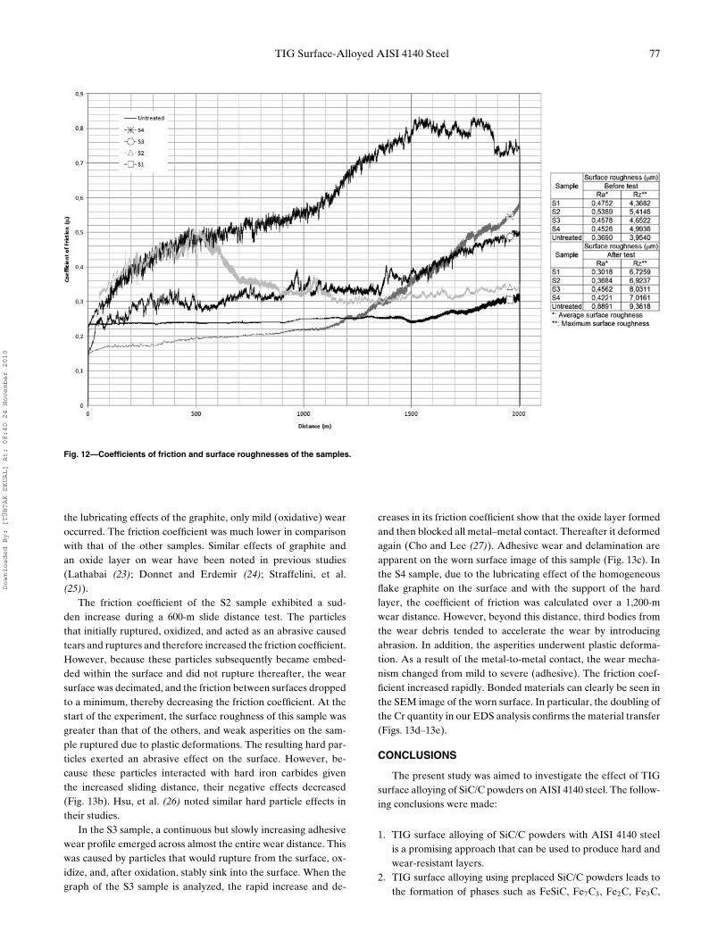
Figure 12 shows the changes in the friction coefficients withrespect to the wear distance of the samples subjected to TIG sur-face alloying, together with relevant surface roughness values. Asseen from the graph, the friction coefficient (µ) of the S1 samplewas around 0.25, independent of the wear distance. Figures 13a–
Downloaded By: [TÜBTAK EKUAL] At: 08:40 24 November 2010

76 M. ULUTAN ET AL.
Fig. 11—SEM micrographs of the worn surfaces after abrasive wear experiments: (a) S1, load 22 N; (b) S2, load 22 N; (c) S3, load 22 N; (d) S4, load 22 N;(e) S1, load 42 N; (f) S2, load 42 N; (g) S3, load 42 N; and (h) S4, load 42 N, respectively.
13d show the SEM micrographs and EDS analyses of the surfacesof the samples subjected to TIG surface alloying, obtained afterthe adhesive wear experiment. The lowest friction coefficientwas obtained for the S1 sample due to its decreased surfaceroughness, the lubrication effect as a result of the breakdown
of surface graphite islands, and metal oxides that formed on thesurface. The presence of an oxide layer was determined from theEDS analysis of the wear surface of the S1 sample. Also, gapsfrom broken-down graphite particles are apparent (Fig. 13a).As a result of the friction-reducing effects of the oxide layer and
Downloaded By: [TÜBTAK EKUAL] At: 08:40 24 November 2010
TIG Surface-Alloyed AISI 4140 Steel 77
Fig. 12—Coefficients of friction and surface roughnesses of the samples.
the lubricating effects of the graphite, only mild (oxidative) wearoccurred. The friction coefficient was much lower in comparisonwith that of the other samples. Similar effects of graphite andan oxide layer on wear have been noted in previous studies(Lathabai (23); Donnet and Erdemir (24); Straffelini, et al.(25)).
The friction coefficient of the S2 sample exhibited a sud-den increase during a 600-m slide distance test. The particlesthat initially ruptured, oxidized, and acted as an abrasive causedtears and ruptures and therefore increased the friction coefficient.However, because these particles subsequently became embed-ded within the surface and did not rupture thereafter, the wearsurface was decimated, and the friction between surfaces droppedto a minimum, thereby decreasing the friction coefficient. At thestart of the experiment, the surface roughness of this sample wasgreater than that of the others, and weak asperities on the sam-ple ruptured due to plastic deformations. The resulting hard par-ticles exerted an abrasive effect on the surface. However, be-cause these particles interacted with hard iron carbides giventhe increased sliding distance, their negative effects decreased(Fig. 13b). Hsu, et al. (26) noted similar hard particle effects intheir studies.
In the S3 sample, a continuous but slowly increasing adhesivewear profile emerged across almost the entire wear distance. Thiswas caused by particles that would rupture from the surface, ox-idize, and, after oxidation, stably sink into the surface. When thegraph of the S3 sample is analyzed, the rapid increase and de-
creases in its friction coefficient show that the oxide layer formedand then blocked all metal–metal contact. Thereafter it deformedagain (Cho and Lee (27)). Adhesive wear and delamination areapparent on the worn surface image of this sample (Fig. 13c). Inthe S4 sample, due to the lubricating effect of the homogeneousflake graphite on the surface and with the support of the hardlayer, the coefficient of friction was calculated over a 1,200-mwear distance. However, beyond this distance, third bodies fromthe wear debris tended to accelerate the wear by introducingabrasion. In addition, the asperities underwent plastic deforma-tion. As a result of the metal-to-metal contact, the wear mecha-nism changed from mild to severe (adhesive). The friction coef-ficient increased rapidly. Bonded materials can clearly be seen inthe SEM image of the worn surface. In particular, the doubling ofthe Cr quantity in our EDS analysis confirms the material transfer(Figs. 13d–13e).
CONCLUSIONS
The present study was aimed to investigate the effect of TIGsurface alloying of SiC/C powders on AISI 4140 steel. The follow-ing conclusions were made:
1. TIG surface alloying of SiC/C powders with AISI 4140 steelis a promising approach that can be used to produce hard andwear-resistant layers.
2. TIG surface alloying using preplaced SiC/C powders leads tothe formation of phases such as FeSiC, Fe7C3, Fe2C, Fe3C,
Downloaded By: [TÜBTAK EKUAL] At: 08:40 24 November 2010

78 M. ULUTAN ET AL.
Fig. 13—Worn surfaces and EDS analysis of the samples after adhesive wear tests: (a) S1, (b) S2, (c) S3, (d) S4 and (e) S4.
M3C, M7C3, and Fe5C2, depending on the dilution metrics ofthe alloyed layer with respect to Fe and the substrate. Thesehard phases and the dissolution of SiC may increase the hard-ness of the alloyed layers.
3. Hardness and wear resistance of the alloyed layers increasedcompared to the substrate for all samples. The wear resistanceof the alloyed layers was two to three times higher than that of4140 steel substrate at lower loadings. Moreover, the friction
Downloaded By: [TÜBTAK EKUAL] At: 08:40 24 November 2010

TIG Surface-Alloyed AISI 4140 Steel 79
coefficients of all the samples were less than that of the 4140steel substrate. The S1 sample that was produced with the low-est heat input and powder feed rate offered the best frictionproperties. This was probably due to the fact that the negativeeffects of thermal stresses were relatively low for this sample,due to the high processing speed and low initial energy in-put. Additionally, the improvement in wear properties of thesamples was attributed to the presence of graphite in the al-loyed layers, which acted as a solid lubricant during the weartest. Addition of SiC, which dissolved during the alloying pro-cess, improved matrix hardness and produced FeSiC carbideson the alloyed surface. The increasing hardness of the alloyedsurface improved abrasive wear resistance.
REFERENCES(1) Xinhong, W., Lin, C., Min, Z., and Zengda, Z. (2009),” Fabrication of Mul-
tiple Carbide Particles Reinforced Fe-Based Surface Hardfacing LayerProduced by Gas Tungsten Arc Welding Process,” Surface Coatings andTechnology, 203(8), pp 976-980.
(2) Amirsadeghi, A. and Sohi, M. H. (2008), “Comparison of the Influence ofMolybdenum and Chromium TIG Surface Alloying on the Microstructure,Hardness and Wear Resistance of ADI,” Journal of Materials ProcessingTechnology, 201(1-3), pp 673-677.
(3) Ulutan, M. (2007), Investigation of Mechanical Behaviors of an AISI 4140Steel after Surface Hardening and Coating Processes, Doctoral thesis, Es-kisehir Osmangazi University (ESOGU), Department of Mechanical En-gineering, Eskisehir, Turkey.
(4) Wang, S. W., Lin, Y. C., and Tsai, Y. Y. (2003), “The Effects of VariousCeramic–Metal on Wear Performance of Clad Layer,” Journal of MaterialsProcessing Technology, 140(1-3), pp 682-687.
(5) Eroglu, M. and Ozdemir, N. (2002), “Tungsten-Inert Gas Surface Alloyingof a Low Carbon Steel,” Surface Coatings Technology, 154(2-3), pp 209-217.
(6) Eroglu, M. and Onalp, S. (2002), “Tungsten Inert Gas Surface Modifica-tion of SAE 4140 Steel,” Materials Science and Technology, 18, pp 1544-1550.
(7) Cheng, F. T., Lo, K. H., and Man, H. C. (2003), “NiTi Cladding on Stain-less Steel by TIG Surfacing Process Part I. Cavitation Erosion Behavior,”Surface Coatings Technology, 172(2-3), pp 308-315.
(8) Wang, X. H., Song, S. L., Qu, S. Y., and Zou, Z. D. (2007), “Characteriza-tion of in Situ Synthesized TiC Particle Reinforced Fe-Based CompositeCoatings Produced by Multi-Pass Overlapping GTAW Melting Process,”Surface Coatings Technology, 201(12), pp 5899-5905.
(9) Lin, Y.-C., Wang, S.-W., and Lin, Y.-C. (2005), “Analysis of Microstruc-ture and Wear Performance of WC–Ti Clad Layers on Steel, Producedby Gas Tungsten Arc Welding,” Surface Coatings Technology, 200(7), pp2106-2113.
(10) Majumdar, J. D., Chandra, B. R., Nath, A. K., and Manna, I. (2006), “LaserComposite Surfacing of Stainless Steel with SiC,” Physica Status Solidi A,203(9), pp 2260-2265.
(11) Buytoz, S. (2006), “Microstructural Properties of SiC Based Hardfacing onLow Alloy Steel,” Surface Coatings Technology, 200(12-13), pp 3734-3742.
(12) Talas, S. (2006), “Microstructural Characterization of SiC Added Struc-tural Steel,” Kovove Materialy, 44, pp 169-173.
(13) Choo, S. H., Lee, S., and Golkovski, M. G. (2000), “Effects of AcceleratedElectron Beam Irradiation on Surface Hardening and Fatigue Propertiesin an AISI 4140 Steel Used for Automotive Crankshaft,” Materials Scienceand Engineering A, 293(1-2), pp 56-70.
(14) Campbell, F. C. (2006), Manufacturing Technology for Aerospace Struc-tural Materials, 1st ed., Elsevier Ltd.: London.
(15) Medina-Flores, A., Oseguera, J., Santiago, P., and Ascencio, J. A. (2004),“Structural Analysis of AISI-SAE 4140 Steel Nitrided by Post-DischargeMicrowave,” Surface Coatings Technology, 188-189, pp 7-12.
(16) Meysami, A. H., Ghasemzadeh, R., Seyedein, S. H., and Aboutalebi,M. R. (2010), “An Investigation on the Microstructure and MechanicalProperties of Direct-Quenched and Tempered AISI 4140 Steel,” Materials& Design, 31, pp 1570-1575.
(17) Thawari, G., Sundarararjan, G., and Joshi, S. V. (2003), “Laser SurfaceAlloying of Medium Carbon Steel with SiC(P),” Thin Solid Films, 423, pp41-53.
(18) Abbas, G. and Ghazanfar, U. (2005), “Two-Body Abrasive Wear Studiesof Laser Produced Stainless Steel and Stainless Steel + SiC CompositeClads,” Wear, 258, pp 258-264.
(19) Majumdar, J. D., Chandra, B. R., Nath, A. K., and Manna, I. (2008), “Stud-ies on Compositionally Graded Silicon Carbide Dispersed Composite Sur-face on Mild Steel Developed by Laser Surface Cladding,” Journal of Ma-terials Processing Technology, 203(1-3), pp 505-512.
(20) Pero-Sanz, J. A., Plaza, D., Verdeja, J. I., and Asensio, J. (1999), “Metal-lographic Characterization of Hypoeutectic Martensitic White Cast Irons:Fe-C-Cr System,” Materials Characterization, 43, pp 33-39.
(21) Asensio, J., Pero-Sanz, J. A., and Verdeja, J. I. (2003), “MicrostructureSelection Criteria for Cast Irons with More Than 10 wt.% Chromium forWear Applications,” Materials Characterization, 49, pp 83-93.
(22) Jacuinde, A. B. and Rainforth, W. M. (2001), “The Wear Behavior ofHigh-Chromium White Cast Irons as a Function of Silicon and MischmetalContent,” Wear. 250(1-12), pp 449-461.
(23) Lathabai, S. (1998), “An SEM Study of Mild-to-Severe Wear Transitionin Grey Cast Iron during Dry Sliding,” Scripta Materialia, 38(10), pp 1557-1562.
(24) Donnet, C. and Erdemir, A. (2004), “Solid Lubricant Coatings: Recent De-velopments and Future Trends,” Tribology Letters, 17(3), pp 389-397.
(25) Straffelini, G., Trabucco, D., and Molinari, A. (2001), “Oxidative Wear ofHeat-Treated Steels,” Wear, 250(1-12), pp 485-491.
(26) Hsu, S. M., Shen, M. C., and Ruff, A. W. (1997), “Wear Prediction forMetals,” Tribology International, 30(5), pp 377-383.
(27) Cho, C.-W. and Lee, Y.-Z. (2004), “Friction Transition Diagram Consid-ering the Effects of Oxide Layer Formed on Wear Track of AISI 1045Steel Disk against TiN Coated AISI 52100 Steel Ball in Sliding,” SurfaceCoatings Technology, 179(1), pp 1-9.
Downloaded By: [TÜBTAK EKUAL] At: 08:40 24 November 2010