Migatronic Tig - Plasma Welding machine /Fanuc robot ...
22
1 / 22 U:\RS_INTFS\WORD\OPSTILL.DOC 29/04/2011 15:48 PH/CL Migatronic Tig - Plasma Welding machine /Fanuc robot Interface Adapted for RJ3 Controller: 76119997-1 Adapted for RJ2 Controller: 76119999-1 Setup & Jumper configuration AUTOMATION A/S +45 96 96 27 00
-
Upload
khangminh22 -
Category
Documents
-
view
1 -
download
0
Transcript of Migatronic Tig - Plasma Welding machine /Fanuc robot ...

1 / 22 �U:\RS_INTFS\WORD\OPSTILL.DOC � 29/04/2011 � 15:48 PH/CL
Migatronic Tig - Plasma Welding machine /Fanuc robot Interface
Adapted for RJ3 Controller: 76119997-1 Adapted for RJ2 Controller: 76119999-1
Setup & Jumper configuration
AUTOMATION A/S +45 96 96 27 00

2 / 22 �U:\RS_INTFS\WORD\OPSTILL.DOC � 29/04/2011 � 15:48 PH/CL
Table of Contents: JUMPERS. ................................................................................................................................................................................................................................... 3
LED INDICATORS..................................................................................................................................................................................................................... 4
CONNECTIONS IN FRONT OF THE INTERFACE. ............................................................................................................................................................ 5
CONNECTIONS ON BACKSIDE OF THE INTERFACE. .................................................................................................................................................... 7
INTERFACE SCHEMATIC ...................................................................................................................................................................................................... 8
ACCESSORIES........................................................................................................................................................................................................................... 9
ILLUSTRATION 1: THE WELDING MACHINE GIVES THE ARC DETECT SIGNAL THROUGH THE COLD WIRE FEEDER....................... 11
ILLUSTRATION 2: THE WELDING MACHINE GIVES THE ARC DETECT SIGNAL THROUGH THE COLD WIRE FEEDER....................... 12
ILLUSTRATION 3: THE WELDING MACHINE GIVES THE ARC DETECT SIGNAL............................................................................................... 13
ILLUSTRATION 4: THE WELDING MACHINE GIVES THE ARC DETECT SIGNAL............................................................................................... 14
ILLUSTRATION 5: THE ARC DETECTOR BOX GIVES THE ARC DETECT SIGNAL. ............................................................................................ 15
ILLUSTRATION 6: THE ARC DETECTOR BOX GIVES THE ARC DETECT SIGNAL. ............................................................................................ 16
ILLUSTRATION 7: THE ARC DETECTOR BOX GIVES THE ARC DETECT SIGNAL. ............................................................................................ 17
ILLUSTRATION 8: THE ARC DETECTOR BOX GIVES THE ARC DETECT SIGNAL. ............................................................................................ 18
ILLUSTRATION 9: THE AC/DC ARC DETECTOR BOX GIVES THE ARC DETECT SIGNAL THROUGH THE COLD WIRE FEEDER........ 19
ILLUSTRATION 10: THE AC/DC ARC DETECTOR BOX GIVES THE ARC DETECT SIGNAL THROUGH THE COLD WIRE FEEDER...... 20
ILLUSTRATION 11: THE AC/DC ARC DETECTOR BOX GIVES THE ARC DETECT SIGNAL. ............................................................................. 21
ILLUSTRATION 12: THE AC/DC ARC DETECTOR BOX GIVES THE ARC DETECT SIGNAL. ............................................................................. 22
3 / 22 �U:\RS_INTFS\WORD\OPSTILL.DOC � 29/04/2011 � 15:48 PH/CL
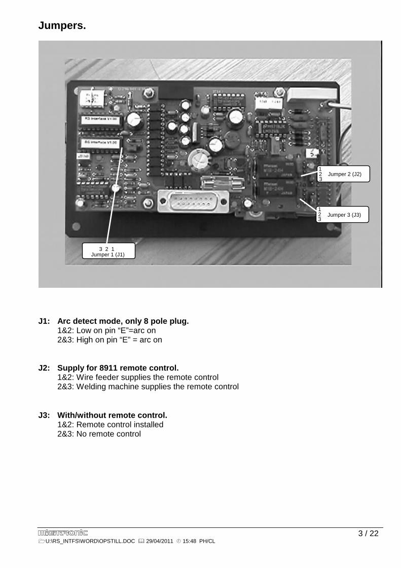
Jumpers.
Jumper 1 (J1)3 2 1
Jumper 2 (J2)
Jumper 3 (J3)
2 1
3
12 3
J1: Arc detect mode, only 8 pole plug. 1&2: Low on pin “E”=arc on 2&3: High on pin “E” = arc on J2: Supply for 8911 remote control. 1&2: Wire feeder supplies the remote control 2&3: Welding machine supplies the remote control J3: With/without remote control. 1&2: Remote control installed 2&3: No remote control

4 / 22 �U:\RS_INTFS\WORD\OPSTILL.DOC � 29/04/2011 � 15:48 PH/CL
Led indicators.
1
2
3
4 5
6
7
8
9 1011
12
Pos.1: Current output signal, PWM signal (Yellow) Pos.2: Wire speed output signal, PWM signal (Yellow) Pos.3: Start welding input from robot (Yellow) Pos.4: Start wire/wire on input from robot (Yellow) Pos.5: Wire + input signal from robot (Yellow) Pos.6: Wire – input signal from robot )Yellow) Pos.7: Arc on signal from 6 pole plug, input signal (Yellow) Pos.8: Arc on signal from 8 pole plug, input signal (Yellow) Pos.9: Start welder output signal (Red) Pos.10: Start/wire on, output signal (Red) Pos.11: Arc on, output signal to the robot (Red) Pos. 12: +24V DC from robot OK (Green)

5 / 22 �U:\RS_INTFS\WORD\OPSTILL.DOC � 29/04/2011 � 15:48 PH/CL
Connections in front of the interface.
1: Start wirefeeder / welding machine output.
Via this connector, the KT-4 wire feeder is started. This connector also can supply the interface with the Arc Detect signal.
Pinconnections: 2: Relay output. Start welding machine or wire feeder. 3: Arc Detect signal. Input to interface. 5: 0V / Gnd. 6: Relay output. Start welding machine or wire feeder.
Other pins not connected. 2: Connection to welding machine´s remote input. This plug should only be connected if no wire feeder is connected. Pinconnections: A: Current information 0-10V to welding machine. B: 0V/GND (REF.0V) E: Arc Detect signal from welding machine. 0V = Arc ON. G: Supply voltage. Voltage = 18VAC or 24VAC, depending on welding machine. H: Supply voltage common.
Other pins not connected.
2
3
4
1

6 / 22 �U:\RS_INTFS\WORD\OPSTILL.DOC � 29/04/2011 � 15:48 PH/CL
3: Connector to KT4 wire feeder. Pin connections: A: Current information 0-10V DC. From interface to welding machine. B: 0V/GND (REF.0V). C: Wirefeeder ground/ connected to the chassis in wirefeeder. D: Direction signal wire. “0” = wire forward. “1” = Wire return. E: Start wire request from wirefeeder. Output from KT-4 wire feeder. F: Start wire: Input on KT-4 wire feeder. “0” = Stop wire. “1” = Start wire. G: +24V / DC to remote control. Max. 200mA. Short circuit protected. H: 0V / GND to remote control. M: Wirespeed information 0 to 10V. From remote control to wire feeder. V: Interface ground / connected to chassis in interface.
Other pins not connected. 4: Connector to remote control from interface.
Remote control type 8911 can be used.
Pin connections: A: Current information 0-10V DC. From interface to welding machine. B: 0V/GND (REF.0V). C: Wirefeeder ground/ connected to the chassis in wirefeeder. D: Direction signal wire. “0” = wire forward. “1” = Wire return. E: Start wire request from wirefeeder. Output from KT-4 wire feeder. F: Start wire: Input on KT-4 wire feeder. “0” = Stop wire. “1” = Start wire. G: +24V / DC to remote control. Max. 200mA. Short circuit protected. H: 0V / GND to remote control. J: Enable Basis Current. A “0” on this input, will force the remote control to enable
basis current. A ”1” will enable the remote control to carry out it’s normal procedure. K: 0V/GND. L: 0V/GND.
M: Wirespeed information 0 to 10V. From remote control to wire feeder. N: Wire +. “0” = Jog wire.
P: Wire -. “0” = Jog wire direction. R: Disable puls current. “0” = No current pulsation. S: Disable step wire. “0” = Constant wire. “1” = Wire when current is high. T: Wire speed information 0 to 10V, from robot. U: Current information 0 to 10V, from robot. V: Interface ground / connected to chassis in remote control.
Other pins not connected.

7 / 22 �U:\RS_INTFS\WORD\OPSTILL.DOC � 29/04/2011 � 15:48 PH/CL
Connections on backside of the interface.
Pin numbers and names in parenthesis refer to connectors on a Fanuc robot’s RJ2 or RJ3 controller. 1: Welding current + (CRW1-23, WDO1). 2: Wire speed + (CRW1-3, DACH2). 3: NC. 4: 0V / Ground in robot (CRW1-20, GND). 5: Arc Detect output from interface to robot (CRW1-6, WDI2). 6: Disable pulse current (CRW1-28, WDO6). 7: Wire +, jog wire forward (CRW1-26, WDO4). 8: Start weld (CRW1-23, WDO1). 9: Welding current – (CRW1-2, CAMDA1). 10: Wire speed – (CRW1-4, CAMDA2). 11: Enable basis current (CRM2B-33, SDO1). 12: +24VDC from robot (CRW1-34, +24VE). 13: Disable step wire (CRW1-29, WDO7). 14: Wire -, jog wire backward (CRW1-27, WDO5). 15: Start wire (CRW1-25, WDO3). All inputs to the interface via this connector, except analogue inputs, requires NPN open collector output type, or relay contact - switching to 0V. All outputs from the interface via this connector, are NPN open collector type.
1

8 / 22 �U:\RS_INTFS\WORD\OPSTILL.DOC � 29/04/2011 � 15:48 PH/CL
Interface Schematic

9 / 22 �U:\RS_INTFS\WORD\OPSTILL.DOC � 29/04/2011 � 15:48 PH/CL
Accessories
6 pole cable between RS interface and arc detector box. The cable must be full connected. Male / female. Length standard 3 meters . No. 74341020-1
6 pole cable between RS interface and cold wire feeder. The cable must be full connected. Male / male. Length standard 5 meters . No. 74341021-1
6 pole cable. Start welding machine. Male / male. Only pin 2 & 6 is connected. Length standard 5 meters. No. 74320002-1
8 pole cable between RS interface and welding machine. The cable must be full connected. Length standard 5 meters. Male / male. No. 74340003-0
19 pole cable between RS interface and cold wire feeder. Also used between RS interface and 8911 remote control. Length standard 6 meters. The cable must be full connected. Male / male. No. 74341011-1
Remote control 8911 Controls welding current, cold wire speed and pulse timing. No. 76118911-1
Arc detector box. Usable only for DC welding Detects current > 20A No. 76118817-1

10 / 22 �U:\RS_INTFS\WORD\OPSTILL.DOC � 29/04/2011 � 15:48 PH/CL
76118818-1
WIRE FEEDER
GROUND
WELDING MACHINE
WELDING +
Arc detector box. Can also be used for AC welding Detects current > 5A No. 76118818-1
19-Pin plug with bridges. Use when the system is equipped with wire feeder, and NOT equipped with remote control. No. 17210090-1

11/22 � U:\RS_INTFS\WORD\OPSTILL.DOC � 29/04/2011 � 15:48 PH/CL
Illustration 1: The welding machine gives the arc detect signal through the cold wire feeder. RS interface jumpers: J1: 2&3, J2: 1&2, J3: 1&2
To be used in connection with: Plasma commander DC, Tig Commander/Navigator DC. It can be necessary to apply PTC1 in the control unit on the welding machine (Analogue machines only).

12/22 � U:\RS_INTFS\WORD\OPSTILL.DOC � 29/04/2011 � 15:48 PH/CL
Illustration 2: The welding machine gives the arc detect signal through the cold wire feeder. RS interface jumpers: J1: 2&3, J2: 1&2, J3: 2&3
To be used in connection with: Plasma commander DC, Tig Commander/Navigator DC. It can be necessary to apply PTC1 in the control unit on the welding machine (Analogue machines only). Note! 19-Pin plug (part no.17210090-1), must be inserted in the remote control connector, at the
interface.

13/22 � U:\RS_INTFS\WORD\OPSTILL.DOC � 29/04/2011 � 15:48 PH/CL
Illustration 3: The welding machine gives the arc detect signal.
RS interface jumpers: J1: 1&2, J2: 2&3, J3: 1&2
To be used in connection with: Plasma commander DC, Tig Commander/Navigator DC. It can be necessary to apply PTC1 in the control unit on the welding machine (Analogue machines only).
14/22 � U:\RS_INTFS\WORD\OPSTILL.DOC � 29/04/2011 � 15:48 PH/CL
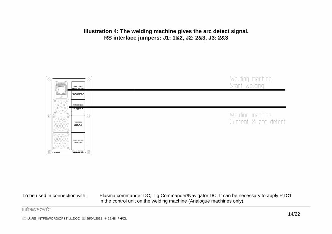
Illustration 4: The welding machine gives the arc detect signal.
RS interface jumpers: J1: 1&2, J2: 2&3, J3: 2&3
To be used in connection with: Plasma commander DC, Tig Commander/Navigator DC. It can be necessary to apply PTC1 in the control unit on the welding machine (Analogue machines only).

15/22 � U:\RS_INTFS\WORD\OPSTILL.DOC � 29/04/2011 � 15:48 PH/CL
Illustration 5: The arc detector box gives the arc detect signal. RS interface jumpers: J1: 2&3, J2: 1&2, J3: 1&2
To be used in connection with: Pilot 1600/2400, BDH Tig. DC welding only. It can be necessary to remove wire ”E” in the 8 pole Cable between the welding machine and the cold wire feeder.
16/22 � U:\RS_INTFS\WORD\OPSTILL.DOC � 29/04/2011 � 15:48 PH/CL
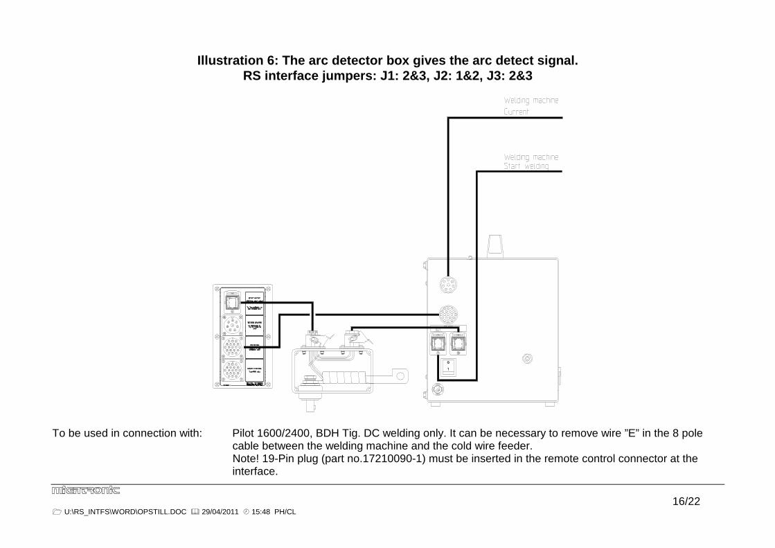
Illustration 6: The arc detector box gives the arc detect signal. RS interface jumpers: J1: 2&3, J2: 1&2, J3: 2&3
To be used in connection with: Pilot 1600/2400, BDH Tig. DC welding only. It can be necessary to remove wire ”E” in the 8 pole cable between the welding machine and the cold wire feeder. Note! 19-Pin plug (part no.17210090-1) must be inserted in the remote control connector at the interface.
17/22 � U:\RS_INTFS\WORD\OPSTILL.DOC � 29/04/2011 � 15:48 PH/CL
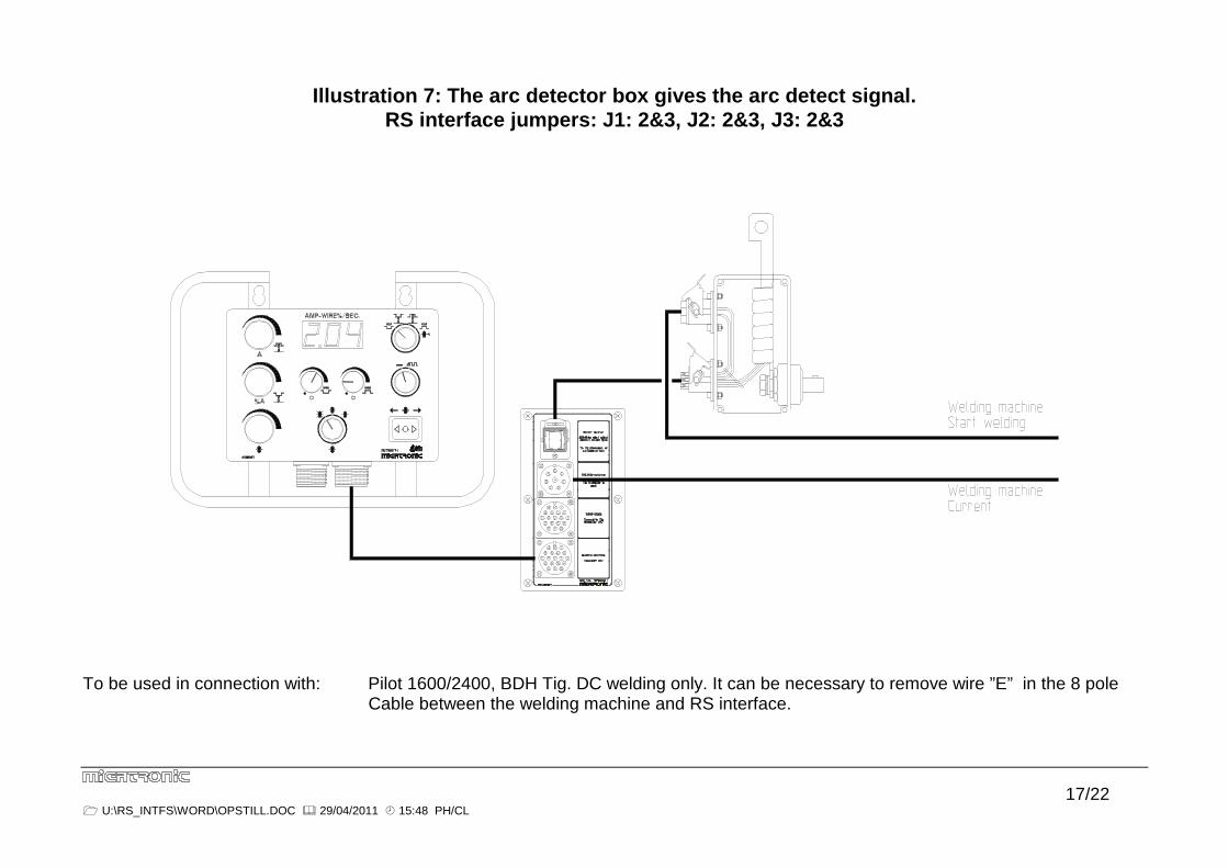
Illustration 7: The arc detector box gives the arc detect signal. RS interface jumpers: J1: 2&3, J2: 2&3, J3: 2&3
To be used in connection with: Pilot 1600/2400, BDH Tig. DC welding only. It can be necessary to remove wire ”E” in the 8 pole Cable between the welding machine and RS interface.

18/22 � U:\RS_INTFS\WORD\OPSTILL.DOC � 29/04/2011 � 15:48 PH/CL
Illustration 8: The arc detector box gives the arc detect signal. RS interface jumpers: J1: 2&3, J2: 2&3, J3: 2&3
To be used in connection with: Pilot 1600/2400, BDH Tig. DC welding only. It can be necessary to remove wire ”E” in the 8 pole
cable between the welding machine and RS interface.

19/22 � U:\RS_INTFS\WORD\OPSTILL.DOC � 29/04/2011 � 15:48 PH/CL
Illustration 9: The AC/DC Arc detector box gives the arc detect signal through the cold wire feeder. RS interface jumpers: J1: 1&2, J2: 1&2, J3: 1&2
To be used in connection with: Plasma commander AC/DC, Tig Commander/Navigator AC/DC.
It can be necessary to apply PTC1 in the control unit on the welding machine (Analogue machines only).

20/22 � U:\RS_INTFS\WORD\OPSTILL.DOC � 29/04/2011 � 15:48 PH/CL
Illustration 10: The AC/DC Arc detector box gives the arc detect signal through the cold wire feeder. interface jumpers: J1: 1&2, J2: 2&3, J3: 2&3
To be used in connection with: Plasma commander AC/DC, Tig Commander/Navigator AC/DC. It can be necessary to apply PTC1 in the control unit on the welding machine (Analogue machines only).
Note! 19-Pin plug (part no.17210090-1) must be inserted in the remote control connector at the interface.
21/22 � U:\RS_INTFS\WORD\OPSTILL.DOC � 29/04/2011 � 15:48 PH/CL
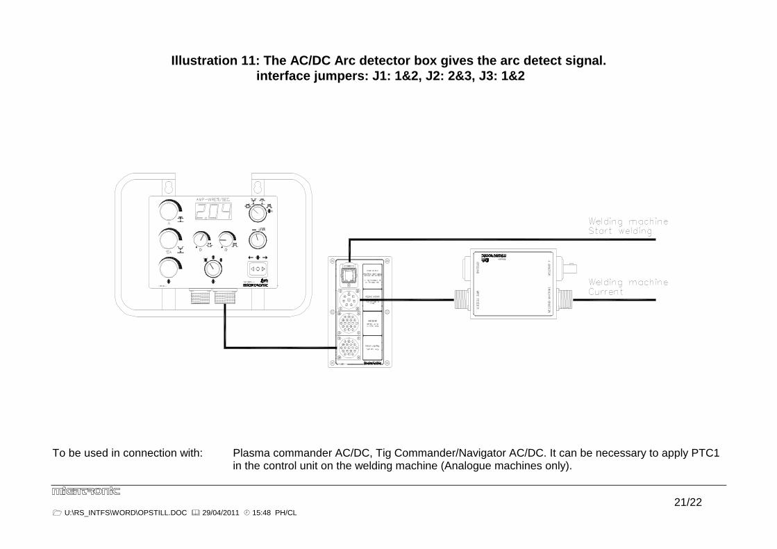
Illustration 11: The AC/DC Arc detector box gives the arc detect signal. interface jumpers: J1: 1&2, J2: 2&3, J3: 1&2
To be used in connection with: Plasma commander AC/DC, Tig Commander/Navigator AC/DC. It can be necessary to apply PTC1 in the control unit on the welding machine (Analogue machines only).
22/22 � U:\RS_INTFS\WORD\OPSTILL.DOC � 29/04/2011 � 15:48 PH/CL
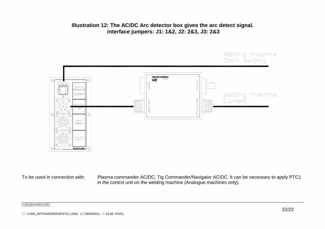
Illustration 12: The AC/DC Arc detector box gives the arc detect signal. interface jumpers: J1: 1&2, J2: 2&3, J3: 2&3
To be used in connection with: Plasma commander AC/DC, Tig Commander/Navigator AC/DC. It can be necessary to apply PTC1 in the control unit on the welding machine (Analogue machines only).