Improving the mechanical properties of TIG welding Ti-6Al-4V ...
Upload
khangminh22Category
view
0download
0
0740 800 116 Valid for serial no. 745--xxx--xxxx to 011--xxx--xxxx040820
LTN 255
Aristotig 255
Service manual

-- 2 --conte
LIST OF CONTENTS Page
READ THIS FIRST 3. . . . . . . . . . . . . . . . . . . . . . . . . . . . . . . . . . . . . . . . . . . . . . . . . . . . . . . . . . . . . . . .
COMPONENT DESCRIPTION 5. . . . . . . . . . . . . . . . . . . . . . . . . . . . . . . . . . . . . . . . . . . . . . . . . . . . . .
CONNECTION DIAGRAM 8. . . . . . . . . . . . . . . . . . . . . . . . . . . . . . . . . . . . . . . . . . . . . . . . . . . . . . . . . .
AP01 DESCRIPTION OF OPERATION 10. . . . . . . . . . . . . . . . . . . . . . . . . . . . . . . . . . . . . . . . . . . . . .
1 Power supply 10. . . . . . . . . . . . . . . . . . . . . . . . . . . . . . . . . . . . . . . . . . . . . . . . . . . . . . . . . . . . . . . .
2 Power supply monitoring 11. . . . . . . . . . . . . . . . . . . . . . . . . . . . . . . . . . . . . . . . . . . . . . . . . . . . . .
3 Start / Stop input 12. . . . . . . . . . . . . . . . . . . . . . . . . . . . . . . . . . . . . . . . . . . . . . . . . . . . . . . . . . . . .
4 Remote control input 12. . . . . . . . . . . . . . . . . . . . . . . . . . . . . . . . . . . . . . . . . . . . . . . . . . . . . . . . .
5 Shunt input with amplifier AP10 13. . . . . . . . . . . . . . . . . . . . . . . . . . . . . . . . . . . . . . . . . . . . . . . .
6 Arc voltage monitoring 14. . . . . . . . . . . . . . . . . . . . . . . . . . . . . . . . . . . . . . . . . . . . . . . . . . . . . . . .
7 HF generator 14. . . . . . . . . . . . . . . . . . . . . . . . . . . . . . . . . . . . . . . . . . . . . . . . . . . . . . . . . . . . . . . .
8 Gas valve 15. . . . . . . . . . . . . . . . . . . . . . . . . . . . . . . . . . . . . . . . . . . . . . . . . . . . . . . . . . . . . . . . . . .
9 Machine type indicator 15. . . . . . . . . . . . . . . . . . . . . . . . . . . . . . . . . . . . . . . . . . . . . . . . . . . . . . . .
10 Thermal overload cutout 15. . . . . . . . . . . . . . . . . . . . . . . . . . . . . . . . . . . . . . . . . . . . . . . . . . . . . .
11 Welding process control 16. . . . . . . . . . . . . . . . . . . . . . . . . . . . . . . . . . . . . . . . . . . . . . . . . . . . . . .
Hot start MMA 16. . . . . . . . . . . . . . . . . . . . . . . . . . . . . . . . . . . . . . . . . . . . . . . . . . . . . . . . . . . . . . .
12 Control panel interface circuits 17. . . . . . . . . . . . . . . . . . . . . . . . . . . . . . . . . . . . . . . . . . . . . . . . .
13 Pulse width modulator 18. . . . . . . . . . . . . . . . . . . . . . . . . . . . . . . . . . . . . . . . . . . . . . . . . . . . . . . .
14 Gate circuit 18. . . . . . . . . . . . . . . . . . . . . . . . . . . . . . . . . . . . . . . . . . . . . . . . . . . . . . . . . . . . . . . . . .
Checking the gate pulses 19. . . . . . . . . . . . . . . . . . . . . . . . . . . . . . . . . . . . . . . . . . . . . . . . . . . . .
Component positions, circuit board AP01 21. . . . . . . . . . . . . . . . . . . . . . . . . . . . . . . . . . . . . . . . . . .
TRANSISTOR BOARD AP02 22. . . . . . . . . . . . . . . . . . . . . . . . . . . . . . . . . . . . . . . . . . . . . . . . . . . . . .
TRANSISTOR BOARD AP03 24. . . . . . . . . . . . . . . . . . . . . . . . . . . . . . . . . . . . . . . . . . . . . . . . . . . . . .
MOS TESTER 26. . . . . . . . . . . . . . . . . . . . . . . . . . . . . . . . . . . . . . . . . . . . . . . . . . . . . . . . . . . . . . . . . . . .
SOFT STARTING 27. . . . . . . . . . . . . . . . . . . . . . . . . . . . . . . . . . . . . . . . . . . . . . . . . . . . . . . . . . . . . . . . .
CONTROL PANEL AP05 28. . . . . . . . . . . . . . . . . . . . . . . . . . . . . . . . . . . . . . . . . . . . . . . . . . . . . . . . . .
DISPLAY BOARD AP06 30. . . . . . . . . . . . . . . . . . . . . . . . . . . . . . . . . . . . . . . . . . . . . . . . . . . . . . . . . . .
AP07 SUPPRESSION BOARD 31. . . . . . . . . . . . . . . . . . . . . . . . . . . . . . . . . . . . . . . . . . . . . . . . . . . . . .
SUPPRESSION BOARD AP08 32. . . . . . . . . . . . . . . . . . . . . . . . . . . . . . . . . . . . . . . . . . . . . . . . . . . . .
SUPPRESSION BOARD AP09 33. . . . . . . . . . . . . . . . . . . . . . . . . . . . . . . . . . . . . . . . . . . . . . . . . . . . .
FAULT CODES 34. . . . . . . . . . . . . . . . . . . . . . . . . . . . . . . . . . . . . . . . . . . . . . . . . . . . . . . . . . . . . . . . . . .
DISASSEMBLY / REASSEMBLY 36. . . . . . . . . . . . . . . . . . . . . . . . . . . . . . . . . . . . . . . . . . . . . . . . . . . .
Fitting the diode modules 36. . . . . . . . . . . . . . . . . . . . . . . . . . . . . . . . . . . . . . . . . . . . . . . . . . . . . . . . .
Removal of transistor circuit boards AP02 and AP03 37. . . . . . . . . . . . . . . . . . . . . . . . . . . . . . . . .
Refitting the transistor circuit board 37. . . . . . . . . . . . . . . . . . . . . . . . . . . . . . . . . . . . . . . . . . . . . . . .
Fitting the main transformer TC02 38. . . . . . . . . . . . . . . . . . . . . . . . . . . . . . . . . . . . . . . . . . . . . . . . .
TECHNICAL DATA 39. . . . . . . . . . . . . . . . . . . . . . . . . . . . . . . . . . . . . . . . . . . . . . . . . . . . . . . . . . . . . . . .
LOAD CHARACTERISTICS 40. . . . . . . . . . . . . . . . . . . . . . . . . . . . . . . . . . . . . . . . . . . . . . . . . . . . . . . .
MAINTENANCE 40. . . . . . . . . . . . . . . . . . . . . . . . . . . . . . . . . . . . . . . . . . . . . . . . . . . . . . . . . . . . . . . . . . .
INSTRUCTIONS 41. . . . . . . . . . . . . . . . . . . . . . . . . . . . . . . . . . . . . . . . . . . . . . . . . . . . . . . . . . . . . . . . . .
INTRODUCTION 41. . . . . . . . . . . . . . . . . . . . . . . . . . . . . . . . . . . . . . . . . . . . . . . . . . . . . . . . . . . . . . . . .
INSTALLATION 42. . . . . . . . . . . . . . . . . . . . . . . . . . . . . . . . . . . . . . . . . . . . . . . . . . . . . . . . . . . . . . . . . .
OPERATION 43. . . . . . . . . . . . . . . . . . . . . . . . . . . . . . . . . . . . . . . . . . . . . . . . . . . . . . . . . . . . . . . . . . . . .
Control panel 44. . . . . . . . . . . . . . . . . . . . . . . . . . . . . . . . . . . . . . . . . . . . . . . . . . . . . . . . . . . . . . . . . . .
Other functions 47. . . . . . . . . . . . . . . . . . . . . . . . . . . . . . . . . . . . . . . . . . . . . . . . . . . . . . . . . . . . . . . . . .
SPARE PARTS 47. . . . . . . . . . . . . . . . . . . . . . . . . . . . . . . . . . . . . . . . . . . . . . . . . . . . . . . . . . . . . . . . . . .
NOTES 48. . . . . . . . . . . . . . . . . . . . . . . . . . . . . . . . . . . . . . . . . . . . . . . . . . . . . . . . . . . . . . . . . . . . . . . . . .
Rights reserved to alter specifications without notice.

-- 3 --cltn1de1
READ THIS FIRST
Maintenance and repair work should be performed by an experienced person, and electricalwork only by a trained electrician. Use only recommended replacement parts.
This service manual is intended for use by technicians with electrical/electronic training forhelp in connection with fault--tracing and repair.
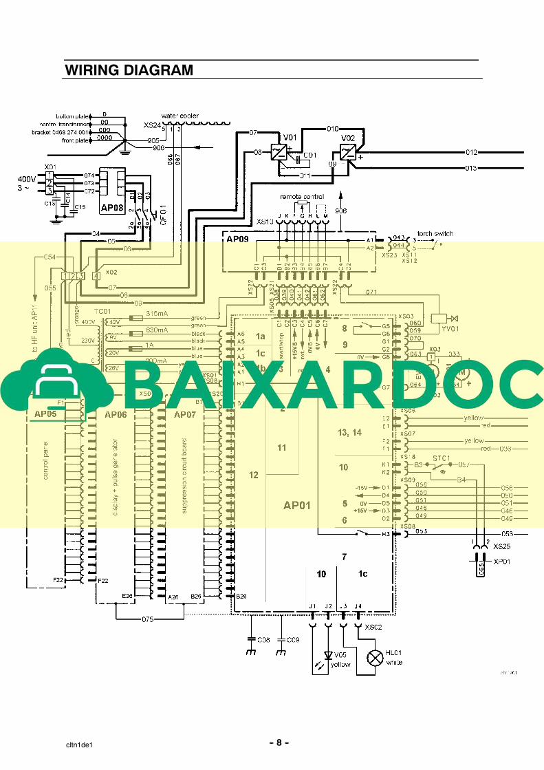
Use the wiring diagram as a form of index for the description of operation. The circuitboard is divided into numbered blocks, which are described individually in more detail inthe description of operation. All component names in the wiring diagram are listed in thecomponent description.
This manual contains details of all design changes that have been made up to and includingAugust 2004.
The LTN 255 is designed and tested in accordance with international and Europeanstandard IEC/EN 60974--1 and EN 50199.On completion of service or repair work, it is the responsibility of the person(s) etc.performing the work to ensure that the product does not depart from the requirementsof the above standard.
WARNING
READ AND UNDERSTAND THE INSTRUCTION MANUAL BEFORE INSTALLING OR OPERATING.
ARC WELDING AND CUTTING CAN BE INJURIOUS TO YOURSELF AND OTHERS. TAKE PRECAU-TIONS WHEN WELDING. ASK FOR YOUR EMPLOYER’S SAFETY PRACTICES WHICH SHOULD BEBASED ON MANUFACTURERS’ HAZARD DATA.
ELECTRIC SHOCK -- Can killS Install and earth the welding unit in accordance with applicable standards.S Do not touch live electrical parts or electrodes with bare skin, wet gloves or wet clothing.S Insulate yourself from earth and the workpiece.S Ensure your working stance is safe.
FUMES AND GASES -- Can be dangerous to healthS Keep your head out of the fumes.S Use ventilation, extraction at the arc, or both, to keep fumes and gases from your breathing zone and
the general area.
ARC RAYS -- Can injure eyes and burn skin.S Protect your eyes and body. Use the correct welding screen and filter lens and wear protective
clothing.S Protect bystanders with suitable screens or curtains.
FIRE HAZARDS Sparks (spatter) can cause fire. Make sure therefore that there are no inflammable materials nearby.
NOISE -- Excessive noise can damage hearingS Protect your ears. Use ear defenders or other hearing protection.S Warn bystanders of the risk.
MALFUNCTION -- Call for expert assistance in the event of malfunction.
PROTECT YOURSELF AND OTHERS!

-- 4 --cltn1de1

-- 5 --cltn1de1
COMPONENT DESCRIPTION
This component description refers to the wiring diagram on page 8.
The LTN 255 is a primary--switched power unit, using parallel--connected MOSFET--transis-tors as the switching elements. The switching frequency is 48.5 kHz. The conductinginterval varies between zero and 9.5µs, depending on the welding current output. Theconducting time and frequency are controlled by circuit board AP01.
WARNING !STATIC ELECTRICITY can damage circuitboards and electronic components.
S Observe precautions for handling electrostaticsensitive devices.
S Use proper static--proof bags and boxes.ESD
AP01 The main circuit board with control electronics. See description on page 10.
AP02 Circuit board with power transistors for the positive pole,see description on page 22.WARNING! the transistors are connected to mains voltage potential.
AP03 Circuit board with power transistors for the negative pole,see description on page 24.WARNING! the transistors are connected to mains voltage potential.
AP05 Circuit board control panel. The circuit diagram is shown on page 28.
AP06 Display driver board with pulse generator. The circuit diagram is shown onpage 30.
AP07 Interference suppression circuit board: see the circuit diagram on page 31.
AP08 Interference suppression circuit board. Prevents mains--borne interference.The circuit diagram is shown on page 32.
AP09 Interference suppression circuit board, remote control connector, see thediagram on page 33.
AP10 Circuit board shunt amplifier, see description on page 13.
AP11 HF generator.
C01 Capacitor, 0.1µF, 1000V DC, transient protection.
C02, C03 Capacitors, 1000µF, buffer/smoothing capacitors.Time to discharge after turning off the unit: about two minutes.
C04 Decoupling capacitor, 0.1µF, 1000V DC, protects against HF.
C05 2 -- capacitors, 4.7µF, see L02.

-- 6 --cltn1de1
C06 -- C09 Capacitor, 0.1µF, 400V DC.
C10, C11 Capacitors, 1nF. Protection against transient voltages.
C13 -- C15 Capacitors, 10nF. Protection against transient voltages. The capacitors areonly used together with an old version of circuit board AP08, see page 32.
EV01 Fan, 24V DC, cooling the power components.
EV02 Fan, 24V DC, cooling AP11 and TV01.
HL01 Lamp, 28V, white, lights when mains power is on.
L01 Secondary inductor.
L02 Inductor, forms an LC circuit with C05 and V06 to reduce the risk of arcextinction at low welding currents.When V03 conducts, the LC circuit charges up. The circuit is capable oftemporarily maintaining a high arc voltage at low current, thus reducing therisk of arc extinction.Diode V06 prevents capacitor C05 from going negative.
L03 Ferrite ring core, transient protection.
L04 Ferrite ring core, transient protection.
L05 Ferrite ring core, transient protection.
QF01 Mains power supply switch, 3--pole.
R01 Resistor, 3.9kΩ 5W.
R02 Resistor, 8.2kΩ 5W.
RS01 Shunt, 119mV±1mV at 250A
ST01 Thermal overload cutout, for overload protection, mounted on the weldinginductor winding (L01). Breaks at 130 _C and resets at 100 _C
TC01 Control power transformer. The primary is supplied at 400V, withsecondary output voltages of 9, 20, 26 and 42V.
Fuses are mounted on the control transformer. A number of machinesproduced before week 719 have no fuses. There is no need to fit fuses tothose machines.
TC02 Main transformer. For fitting instructions, see page 38.
TV01 HF transformer.
V01, V02 Mains rectifier bridges, 35A, 1200V. After replacing the rectifier bridges,the machine must be soft--started: see instructions on page 27.

-- 7 --cltn1de1
V03, V04 Rectifier and freewheel diodes.
V03 rectifies the welding current.During the time interval between two voltage pulses from transformerTC02, the freewheel diodes V04 maintain the welding current from inductorL01.
On the cooling fins three diode modules are mounted. Each diode moduleconsists of two diodes. If one module is broken all modules have to bereplaced.
From serial number 011--148--xxxx a new diode module is used. The ratedcurrent for the new module, SCOMES MKK300.4, is 300 A. The ratedcurrent for the old module, Motorola MURP20040CT, is 200 A. Because ofthe higher rating only two modules are needed for the rectifier unit. Theordering no. for the new module is the same as for the old.
For installation instructions, see page 36.
V05 LED, yellow. Lights when thermal cutout ST01 operates (breaks) as aresult of high temperature.
V06 Diode, see L02.
X01 -- X03 Terminal block.
XP01 Pin connector with jumper. Connected when the machine is used withoutwater cooler.
XS . . Sleeve connectors.
XS04 26--pole ribbon cable connector.
XS10 12--pole Burndy contact, for connection of remote control unit.
XS11 TIG central connector: only LTN 255 variant --894.
XS12 2--pole Cannon connector, only LTN 255 variant --895.
XS13 Welding current connector, OKC, only LTN 255 variant --895.
XS14 Welding current terminals, (two), OKC type.
XS20 26--pole connector for ribbon cable.
XS24 Connection for 400V to water cooler. (The water cooler is an accessory,which is mounted under the machine.)
XS25 Connection for water flow guard.
YV01 Solenoid valve.
-- 8 --cltn1de1
WIRING DIAGRAM

-- 9 --cltn1de1
1 POWER SUPPLY 8 GAS VALVE
2 POWER SUPPLY MONITORING 9 MACHINE TYPE SELECTION
3 START/STOP INPUT 10 THERMAL OVERLOAD SWITCH
4 REMOTE CONTROL INPUT 11 WELDING PROCESS CONTROL
5 SHUNT INPUT WITH AMPLIFIER AP10 12 INTERFACE CIRCUITS FOR CONTROL PANEL
6 ARC VOLTAGE SENSING 13 PULSE WIDTH MODULATOR
7 HF UNIT 14 GATE CIRCUIT
-- 10 --cltn1de2
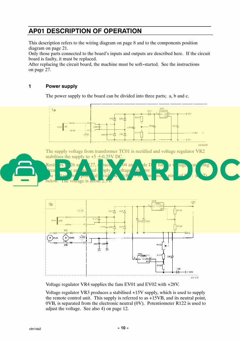
AP01 DESCRIPTION OF OPERATION
This description refers to the wiring diagram on page 8 and to the components positiondiagram on page 21.Only those parts connected to the board’s inputs and outputs are described here. If the circuitboard is faulty, it must be replaced.After replacing the circuit board, the machine must be soft--started. See the instructionson page 27.
1 Power supply
The power supply to the board can be divided into three parts; a, b and c.
cltn0e06
The supply voltage from transformer TC01 is rectified and voltage regulator VR2stabilises the supply to +5¦0.25V DC.
Resistors R126 and R127, capacitor C104 and diode D27 form a voltage monitoringcircuit for the unregulated supply to voltage regulator VR2.The voltage from potential divider R126/R127 is connected to pin 9 of IC7: see 2)below. The voltage is about 2.5V.
Voltage regulator VR4 supplies the fans EV01 and EV02 with +28V.
Voltage regulator VR3 produces a stabilised +15V supply, which is used to supplythe remote control unit. This supply is referred to as +15VB, and its neutral point,0VB, is separated from the electronic neutral (0V). Potentiometer R122 is used toadjust the voltage. See also 4) on page 12.
Copyright © 2022 FDOKUMEN


![Microsoft Word - \256]\255}\277o\275\327\244\345final](https://static.fdokumen.com/doc/165x107/6334cc342532592417003b0e/microsoft-word-256255277o275327244345final.jpg)