Neutralization of local tissue damage induced by (terciopelo) snake venom
Upload
khangminh22Category
view
1download
0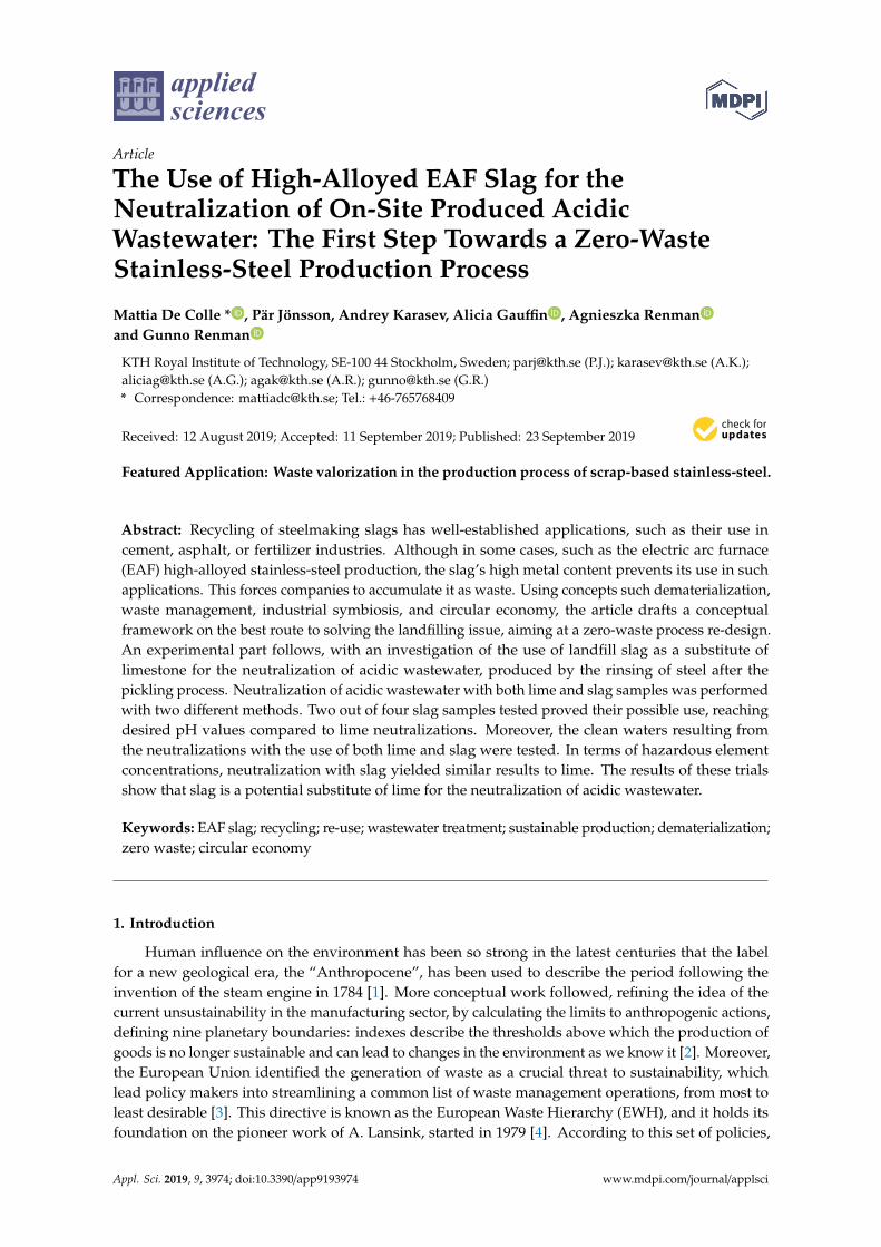
applied sciences
Article
The Use of High-Alloyed EAF Slag for theNeutralization of On-Site Produced AcidicWastewater: The First Step Towards a Zero-WasteStainless-Steel Production Process
Mattia De Colle * , Pär Jönsson, Andrey Karasev, Alicia Gauffin , Agnieszka Renmanand Gunno Renman
KTH Royal Institute of Technology, SE-100 44 Stockholm, Sweden; [email protected] (P.J.); [email protected] (A.K.);[email protected] (A.G.); [email protected] (A.R.); [email protected] (G.R.)* Correspondence: [email protected]; Tel.: +46-765768409
Received: 12 August 2019; Accepted: 11 September 2019; Published: 23 September 2019�����������������
Featured Application: Waste valorization in the production process of scrap-based stainless-steel.
Abstract: Recycling of steelmaking slags has well-established applications, such as their use incement, asphalt, or fertilizer industries. Although in some cases, such as the electric arc furnace(EAF) high-alloyed stainless-steel production, the slag’s high metal content prevents its use in suchapplications. This forces companies to accumulate it as waste. Using concepts such dematerialization,waste management, industrial symbiosis, and circular economy, the article drafts a conceptualframework on the best route to solving the landfilling issue, aiming at a zero-waste process re-design.An experimental part follows, with an investigation of the use of landfill slag as a substitute oflimestone for the neutralization of acidic wastewater, produced by the rinsing of steel after thepickling process. Neutralization of acidic wastewater with both lime and slag samples was performedwith two different methods. Two out of four slag samples tested proved their possible use, reachingdesired pH values compared to lime neutralizations. Moreover, the clean waters resulting fromthe neutralizations with the use of both lime and slag were tested. In terms of hazardous elementconcentrations, neutralization with slag yielded similar results to lime. The results of these trialsshow that slag is a potential substitute of lime for the neutralization of acidic wastewater.
Keywords: EAF slag; recycling; re-use; wastewater treatment; sustainable production; dematerialization;zero waste; circular economy
1. Introduction
Human influence on the environment has been so strong in the latest centuries that the labelfor a new geological era, the “Anthropocene”, has been used to describe the period following theinvention of the steam engine in 1784 [1]. More conceptual work followed, refining the idea of thecurrent unsustainability in the manufacturing sector, by calculating the limits to anthropogenic actions,defining nine planetary boundaries: indexes describe the thresholds above which the production ofgoods is no longer sustainable and can lead to changes in the environment as we know it [2]. Moreover,the European Union identified the generation of waste as a crucial threat to sustainability, whichlead policy makers into streamlining a common list of waste management operations, from most toleast desirable [3]. This directive is known as the European Waste Hierarchy (EWH), and it holds itsfoundation on the pioneer work of A. Lansink, started in 1979 [4]. According to this set of policies,
Appl. Sci. 2019, 9, 3974; doi:10.3390/app9193974 www.mdpi.com/journal/applsci
Appl. Sci. 2019, 9, 3974 2 of 12
landfilling is the least desirable option, and it should be avoided as much as possible. The need forproper waste management, for any manufacturing business, calls for immediate solutions in sectorswhere landfilling is still the primary option. It is with this context in mind that this article was written.The use of slag, to buffer and increase the pH of on-site produced acid wastewater to benefit a circulareconomy and by-product valorization, was studied.
In this study, the overall objective was to investigate whether slag is an effective replacement forslaked lime, since according to the principles of dematerialization this would allow the decouplingfrom raw materials and reduce also the material flow to landfills [5]. The stainless-steel productionprocesses of two steel mills in Sweden, Outokumpu Stainless (OTK) and Sandvik Materials Technology(SMT), were used as case studies. Both companies produce high-alloyed slags which, in the most part,are landfilled. In this study, it was investigated if it was possible to re-use landfill slag to neutralizeacidic wastewater at the respective steel mill. A total of two slag types from each steel mill wereselected and evaluated for their ability to neutralize acidic wastewater produced at the steel mills.The results were also compared with the neutralization performed with the lime products currentlyused at the steel mills. Besides the ability to raise the pH to desired value, the slag should also be ableto remove metals from the wastewater. Such a property was tested in additional trials.
In Sweden, almost 2000 kt of by-products were produced by iron and steelmaking businessesin 2015 alone [6]. Currently, more than 80% of the total amount of iron and steelmaking residues arevalorized. However, specific sectors of steelmaking are struggling more than others to find an adequatesolution, as shown in Figure 1. In most of the sectors listed, the handling of these products, either byinternal or external use, almost completely matches the produced amount. Despite this fact, there aresome critical types of by-products that find little no to application and are currently landfilled.
Appl. Sci. 2019, 9, x FOR PEER REVIEW 2 of 13
possible. The need for proper waste management, for any manufacturing business, calls for immediate solutions in sectors where landfilling is still the primary option. It is with this context in mind that this article was written. The use of slag, to buffer and increase the pH of on-site produced acid wastewater to benefit a circular economy and by-product valorization, was studied.
In this study, the overall objective was to investigate whether slag is an effective replacement for slaked lime, since according to the principles of dematerialization this would allow the decoupling from raw materials and reduce also the material flow to landfills [5]. The stainless-steel production processes of two steel mills in Sweden, Outokumpu Stainless (OTK) and Sandvik Materials Technology (SMT), were used as case studies. Both companies produce high-alloyed slags which, in the most part, are landfilled. In this study, it was investigated if it was possible to re-use landfill slag to neutralize acidic wastewater at the respective steel mill. A total of two slag types from each steel mill were selected and evaluated for their ability to neutralize acidic wastewater produced at the steel mills. The results were also compared with the neutralization performed with the lime products currently used at the steel mills. Besides the ability to raise the pH to desired value, the slag should also be able to remove metals from the wastewater. Such a property was tested in additional trials.
In Sweden, almost 2000 kt of by-products were produced by iron and steelmaking businesses in 2015 alone [6]. Currently, more than 80% of the total amount of iron and steelmaking residues are valorized. However, specific sectors of steelmaking are struggling more than others to find an adequate solution, as shown in Figure 1. In most of the sectors listed, the handling of these products, either by internal or external use, almost completely matches the produced amount. Despite this fact, there are some critical types of by-products that find little no to application and are currently landfilled.
Figure 1. Production and handling of metallurgical slags from iron and steel mills in Sweden during the year 2015. Reproduced with permission from [5], Copyright Jernkontoret, 2018.
Slag derived from the production of high-alloyed electric arc furnace (EAF) stainless-steel, argon oxygen decarburization (AOD) slag, and ladle slag currently suffer from the incapability of being properly valorized. By comparing Error! Reference source not found., it is clear that the reason why the handling of these products is hindered is their alloying elements content. In fact, the most common use for iron and steelmaking slag is the cement and asphalt industry [7]. However, when the materials present high concentrations of metallic or heavy elements, leaching can occur, which impedes the use of these materials for applications where they are subject to weathering [8]. Moreover, EAF slags present phenomena of swelling and disintegration that further impede their use in these types of applications, e.g., asphalt [9]. Therefore, if these products cannot access the market as secondary raw materials via the conventional recycling routes, novel applications need to be drafted to avoid landfilling and increase the sustainability of these processes.
Figure 1. Production and handling of metallurgical slags from iron and steel mills in Sweden duringthe year 2015. Reproduced with permission from [5], Copyright Jernkontoret, 2018.
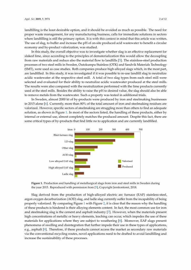
Slag derived from the production of high-alloyed electric arc furnace (EAF) stainless-steel,argon oxygen decarburization (AOD) slag, and ladle slag currently suffer from the incapability of beingproperly valorized. By comparing Figure 1 with Figure 2, it is clear that the reason why the handlingof these products is hindered is their alloying elements content. In fact, the most common use for ironand steelmaking slag is the cement and asphalt industry [7]. However, when the materials presenthigh concentrations of metallic or heavy elements, leaching can occur, which impedes the use of thesematerials for applications where they are subject to weathering [8]. Moreover, EAF slags presentphenomena of swelling and disintegration that further impede their use in these types of applications,e.g., asphalt [9]. Therefore, if these products cannot access the market as secondary raw materialsvia the conventional recycling routes, novel applications need to be drafted to avoid landfilling andincrease the sustainability of these processes.
Appl. Sci. 2019, 9, 3974 3 of 12Appl. Sci. 2019, 9, x FOR PEER REVIEW 3 of 13
Figure 2. Production of metallurgical slag from the iron and steel mills during the year 2015. Reproduced with permission from [5], Copyright Jernkontoret, 2018.
2. The use of slag as a substitute for the lime products used for the neutralization of on-site produced acidic wastewater
Neutralization of acidic wastewater with the use of slaked lime is a well-established and effective process [10] used by both OTK and SMT. Both companies produce acidic wastewater, formed by the rinsing of steel after their respective pickling processes. Lime derived from calcareous limestone is cheap and abundantly produced. It is also applied in other parts of the steelmaking process, thus creating no incentives to stop its use, translating into a situation of technological “lock in” [11], even though the necessity of recirculating slag highlights an opportunity to change the current technology. An inductively coupled plasma mass spectrometry (ICP-MS) analysis has been performed on different slags taken from different parts of the steelmaking processes, both at OTK and SMT [12]. The analysis revealed that all the slag samples presented a calcium content of 30 wt%–40 wt%. Calcium (Ca) in slag has already been identified as the main contributor for the neutralization of acidic solutions [13]; hence, it could be tested as a viable substitute for lime in the neutralization process at OTK and SMT, as well as in other stainless-steel plants.
Figure 2. Production of metallurgical slag from the iron and steel mills during the year 2015. Reproducedwith permission from [5], Copyright Jernkontoret, 2018.
2. The Use of Slag as a Substitute for the Lime Products Used for the Neutralization of On-SiteProduced Acidic Wastewater
Neutralization of acidic wastewater with the use of slaked lime is a well-established and effectiveprocess [10] used by both OTK and SMT. Both companies produce acidic wastewater, formed by therinsing of steel after their respective pickling processes. Lime derived from calcareous limestoneis cheap and abundantly produced. It is also applied in other parts of the steelmaking process,thus creating no incentives to stop its use, translating into a situation of technological “lock in” [11],even though the necessity of recirculating slag highlights an opportunity to change the currenttechnology. An inductively coupled plasma mass spectrometry (ICP-MS) analysis has been performedon different slags taken from different parts of the steelmaking processes, both at OTK and SMT [12].The analysis revealed that all the slag samples presented a calcium content of 30 wt%–40 wt%.Calcium (Ca) in slag has already been identified as the main contributor for the neutralization of acidicsolutions [13]; hence, it could be tested as a viable substitute for lime in the neutralization process atOTK and SMT, as well as in other stainless-steel plants.
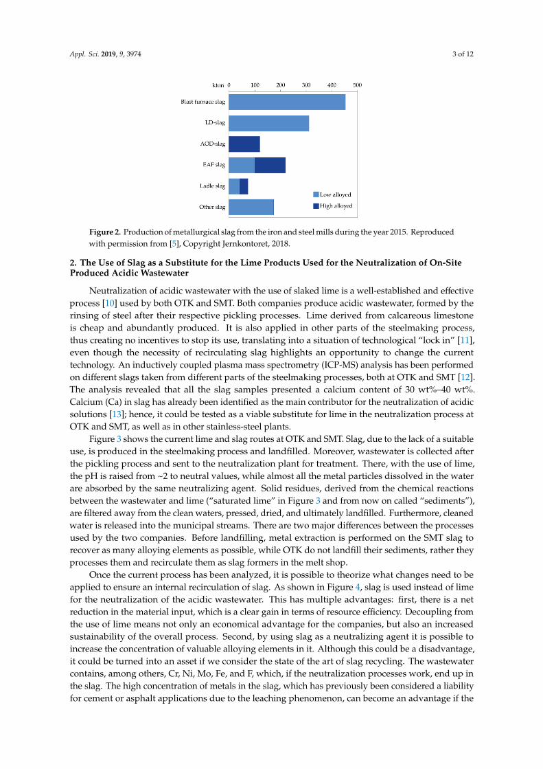
Figure 3 shows the current lime and slag routes at OTK and SMT. Slag, due to the lack of a suitableuse, is produced in the steelmaking process and landfilled. Moreover, wastewater is collected afterthe pickling process and sent to the neutralization plant for treatment. There, with the use of lime,the pH is raised from ~2 to neutral values, while almost all the metal particles dissolved in the waterare absorbed by the same neutralizing agent. Solid residues, derived from the chemical reactionsbetween the wastewater and lime (“saturated lime” in Figure 3 and from now on called “sediments”),are filtered away from the clean waters, pressed, dried, and ultimately landfilled. Furthermore, cleanedwater is released into the municipal streams. There are two major differences between the processesused by the two companies. Before landfilling, metal extraction is performed on the SMT slag torecover as many alloying elements as possible, while OTK do not landfill their sediments, rather theyprocesses them and recirculate them as slag formers in the melt shop.
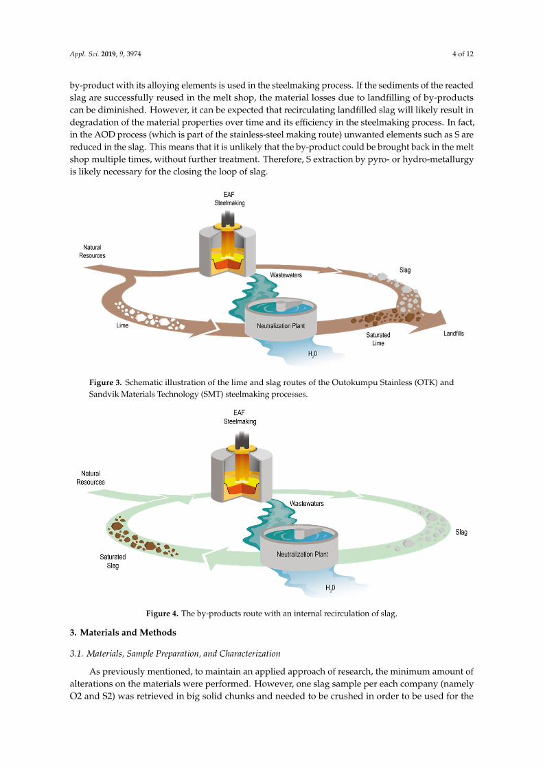
Once the current process has been analyzed, it is possible to theorize what changes need to beapplied to ensure an internal recirculation of slag. As shown in Figure 4, slag is used instead of limefor the neutralization of the acidic wastewater. This has multiple advantages: first, there is a netreduction in the material input, which is a clear gain in terms of resource efficiency. Decoupling fromthe use of lime means not only an economical advantage for the companies, but also an increasedsustainability of the overall process. Second, by using slag as a neutralizing agent it is possible toincrease the concentration of valuable alloying elements in it. Although this could be a disadvantage,it could be turned into an asset if we consider the state of the art of slag recycling. The wastewatercontains, among others, Cr, Ni, Mo, Fe, and F, which, if the neutralization processes work, end up inthe slag. The high concentration of metals in the slag, which has previously been considered a liabilityfor cement or asphalt applications due to the leaching phenomenon, can become an advantage if the
Appl. Sci. 2019, 9, 3974 4 of 12
by-product with its alloying elements is used in the steelmaking process. If the sediments of the reactedslag are successfully reused in the melt shop, the material losses due to landfilling of by-productscan be diminished. However, it can be expected that recirculating landfilled slag will likely result indegradation of the material properties over time and its efficiency in the steelmaking process. In fact,in the AOD process (which is part of the stainless-steel making route) unwanted elements such as S arereduced in the slag. This means that it is unlikely that the by-product could be brought back in the meltshop multiple times, without further treatment. Therefore, S extraction by pyro- or hydro-metallurgyis likely necessary for the closing the loop of slag.
Appl. Sci. 2019, 9, x FOR PEER REVIEW 3 of 13
Figure 2. Production of metallurgical slag from the iron and steel mills during the year 2015. Reproduced with permission from [5], Copyright Jernkontoret, 2018.
2. The use of slag as a substitute for the lime products used for the neutralization of on-site produced acidic wastewater
Neutralization of acidic wastewater with the use of slaked lime is a well-established and effective process [10] used by both OTK and SMT. Both companies produce acidic wastewater, formed by the rinsing of steel after their respective pickling processes. Lime derived from calcareous limestone is cheap and abundantly produced. It is also applied in other parts of the steelmaking process, thus creating no incentives to stop its use, translating into a situation of technological “lock in” [11], even though the necessity of recirculating slag highlights an opportunity to change the current technology. An inductively coupled plasma mass spectrometry (ICP-MS) analysis has been performed on different slags taken from different parts of the steelmaking processes, both at OTK and SMT [12]. The analysis revealed that all the slag samples presented a calcium content of 30 wt%–40 wt%. Calcium (Ca) in slag has already been identified as the main contributor for the neutralization of acidic solutions [13]; hence, it could be tested as a viable substitute for lime in the neutralization process at OTK and SMT, as well as in other stainless-steel plants.
Figure 3. Schematic illustration of the lime and slag routes of the Outokumpu Stainless (OTK) andSandvik Materials Technology (SMT) steelmaking processes.Appl. Sci. 2019, 9, x FOR PEER REVIEW 5 of 13
Figure 4. The by-products route with an internal recirculation of slag.
3. Materials and methods
3.1. Materials, sample preparation, and characterization
As previously mentioned, to maintain an applied approach of research, the minimum amount of alterations on the materials were performed. However, one slag sample per each company (namely O2 and S2) was retrieved in big solid chunks and needed to be crushed in order to be used for the neutralization trials. The method used was a three-step crushing, with the use of a jaw crusher, a spider crusher, and finally a horizontal impact shaft. The other two samples were retrieved from the companies’ landfills (O1 and S1) and were already fine enough powders, but they presented a high level of wetness; hence, they needed to be dried before use in trials. The samples were stored in an oven at 100 °C for 24 h. After crushing and drying, all samples were sieved through a 1 mm mesh to remove all the rocks that were retrieved along with the slags. All the materials that passed through the mesh were used for the trials. Lime samples did not require any preparation before being used. The investigated materials and the performed processing are presented in Table 1.
Table 1. List of materials used and how they were processed before trials.
Material Description Drying Crushing Sieving (1mm) O1 OTK Landfill slag ✓ - ✓ O2 EAF slag - ✓ ✓ S1 SVK Landfill slag ✓ - ✓ S2 AOD slag - ✓ ✓ OL OTK Lime - - - SL SMT Lime - - -
3.1.1. Particle size distribution analysis
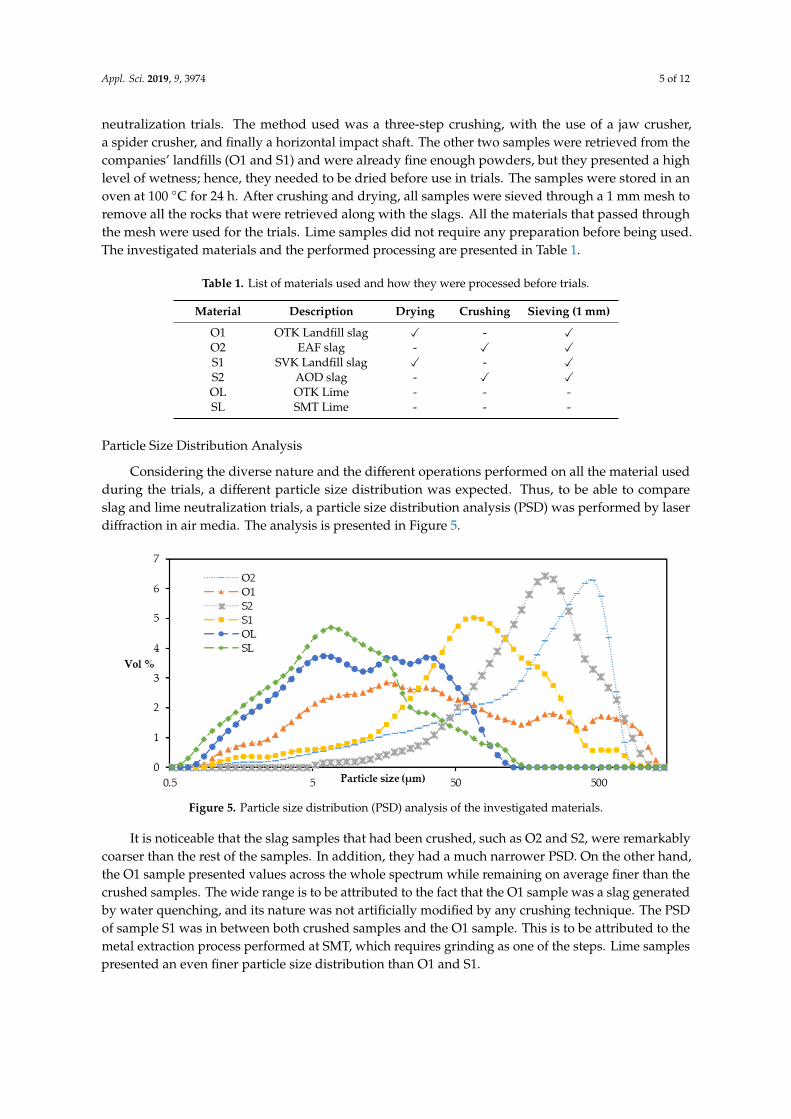
Considering the diverse nature and the different operations performed on all the material used during the trials, a different particle size distribution was expected. Thus, to be able to compare slag and lime neutralization trials, a particle size distribution analysis (PSD) was performed by laser diffraction in air media. The analysis is presented in Figure 5.
Figure 4. The by-products route with an internal recirculation of slag.
3. Materials and Methods
3.1. Materials, Sample Preparation, and Characterization
As previously mentioned, to maintain an applied approach of research, the minimum amount ofalterations on the materials were performed. However, one slag sample per each company (namelyO2 and S2) was retrieved in big solid chunks and needed to be crushed in order to be used for the
Appl. Sci. 2019, 9, 3974 5 of 12
neutralization trials. The method used was a three-step crushing, with the use of a jaw crusher,a spider crusher, and finally a horizontal impact shaft. The other two samples were retrieved from thecompanies’ landfills (O1 and S1) and were already fine enough powders, but they presented a highlevel of wetness; hence, they needed to be dried before use in trials. The samples were stored in anoven at 100 ◦C for 24 h. After crushing and drying, all samples were sieved through a 1 mm mesh toremove all the rocks that were retrieved along with the slags. All the materials that passed throughthe mesh were used for the trials. Lime samples did not require any preparation before being used.The investigated materials and the performed processing are presented in Table 1.
Table 1. List of materials used and how they were processed before trials.
Material Description Drying Crushing Sieving (1 mm)
O1 OTK Landfill slag X - XO2 EAF slag - X XS1 SVK Landfill slag X - XS2 AOD slag - X XOL OTK Lime - - -SL SMT Lime - - -
Particle Size Distribution Analysis
Considering the diverse nature and the different operations performed on all the material usedduring the trials, a different particle size distribution was expected. Thus, to be able to compareslag and lime neutralization trials, a particle size distribution analysis (PSD) was performed by laserdiffraction in air media. The analysis is presented in Figure 5.Appl. Sci. 2019, 9, x FOR PEER REVIEW 6 of 13
Figure 5. Particle size distribution (PSD) analysis of the investigated materials.
It is noticeable that the slag samples that had been crushed, such as O2 and S2, were remarkably coarser than the rest of the samples. In addition, they had a much narrower PSD. On the other hand, the O1 sample presented values across the whole spectrum while remaining on average finer than the crushed samples. The wide range is to be attributed to the fact that the O1 sample was a slag generated by water quenching, and its nature was not artificially modified by any crushing technique. The PSD of sample S1 was in between both crushed samples and the O1 sample. This is to be attributed to the metal extraction process performed at SMT, which requires grinding as one of the steps. Lime samples presented an even finer particle size distribution than O1 and S1.
3.2. Experimental setup
To perform the neutralization trials, a simple experimental setup was designed. Regardless of the method of adding the reactant, the neutralization trials were performed according to the following method. One liter of wastewater was poured into an Erlenmeyer flask that was subsequently placed on top of a magnetic stirrer. After a magnet was placed at the bottom of the flask, the magnetic stirrer was activated and set to an arbitrary speed, which was always kept constant between trials. An arbitrary amount of reactant was weighed and dropped into the flask. Subsequently, the stopwatch was started. More additions were made if the investigation method required it. pH measurements (conducted with the model “sensION p31” calibrated at the start of each trial day with the use of buffers at a pH of 4.01, 7.01, and 10.01) were performed at different times depending on the investigation method until the final pH value was reached. To sample the pH, a rubber tube was inserted in the flask, and without interrupting the stirring with the use of the syringe, around 20 mL of wastewater were taken each time to do the pH measurements. Once the pH was measured, a small wastewater sample was poured back into the flask. The flocculants currently used by the companies in their full-scale processes were added to coalesce the sediments. Then, with the use of filter papers and a funnel, clean waters were separated from the solid particles. Wastewater and clean waters after the neutralization, along with the sediments, were sampled for later studies.
3.2.1. Trial with stepwise dosing of reactant
The rationale behind this trial was to understand the order of magnitude needed for each reactant (lime included) to successfully buffer one liter of wastewater to pH 9. In order to do so, very small additions of reactant were added to the wastewater, and the reaction was maintained until a semi-state of equilibrium between the reactant and the waters was reached (depicted EQ), according to the following experimental procedure:
1. At t = 0 a very small amount of reactant of known weight was added to the wastewater.
Figure 5. Particle size distribution (PSD) analysis of the investigated materials.
It is noticeable that the slag samples that had been crushed, such as O2 and S2, were remarkablycoarser than the rest of the samples. In addition, they had a much narrower PSD. On the other hand,the O1 sample presented values across the whole spectrum while remaining on average finer than thecrushed samples. The wide range is to be attributed to the fact that the O1 sample was a slag generatedby water quenching, and its nature was not artificially modified by any crushing technique. The PSDof sample S1 was in between both crushed samples and the O1 sample. This is to be attributed to themetal extraction process performed at SMT, which requires grinding as one of the steps. Lime samplespresented an even finer particle size distribution than O1 and S1.
Appl. Sci. 2019, 9, 3974 6 of 12
3.2. Experimental Setup
To perform the neutralization trials, a simple experimental setup was designed. Regardless of themethod of adding the reactant, the neutralization trials were performed according to the followingmethod. One liter of wastewater was poured into an Erlenmeyer flask that was subsequently placed ontop of a magnetic stirrer. After a magnet was placed at the bottom of the flask, the magnetic stirrer wasactivated and set to an arbitrary speed, which was always kept constant between trials. An arbitraryamount of reactant was weighed and dropped into the flask. Subsequently, the stopwatch was started.More additions were made if the investigation method required it. pH measurements (conducted withthe model “sensION p31” calibrated at the start of each trial day with the use of buffers at a pH of 4.01,7.01, and 10.01) were performed at different times depending on the investigation method until thefinal pH value was reached. To sample the pH, a rubber tube was inserted in the flask, and withoutinterrupting the stirring with the use of the syringe, around 20 mL of wastewater were taken eachtime to do the pH measurements. Once the pH was measured, a small wastewater sample was pouredback into the flask. The flocculants currently used by the companies in their full-scale processes wereadded to coalesce the sediments. Then, with the use of filter papers and a funnel, clean waters wereseparated from the solid particles. Wastewater and clean waters after the neutralization, along withthe sediments, were sampled for later studies.
3.2.1. Trial With Stepwise Dosing of Reactant
The rationale behind this trial was to understand the order of magnitude needed for each reactant(lime included) to successfully buffer one liter of wastewater to pH 9. In order to do so, very smalladditions of reactant were added to the wastewater, and the reaction was maintained until a semi-stateof equilibrium between the reactant and the waters was reached (depicted EQ), according to thefollowing experimental procedure:
1. At t = 0 a very small amount of reactant of known weight was added to the wastewater.2. At t = 10 min, t = 20 min the pH value was measured.3. At t = 30 min the pH value was measured again, if
∣∣∣pH30 − pH20
∣∣∣ ≤ 0.3, a new quantity of reactantwas added and the procedure repeated. Otherwise, the pH was measured again 10 min later until∣∣∣pHi+10min − pHi
∣∣∣ ≤ 0.3.4. When the pH was 9 ± 0.2, the trial was stopped, and the total amount of reactant used
was calculated.
A final pH of 9 is desired because the industrial neutralization process both at OTK and SMTrequires to reach such value. This is because the absorption of some elements (such as Ni) from thereactant are maximized at high pH levels—hence the need to pass beyond neutral values towards basicones to increase the absorption of such elements. All six reactants were tested, and duplicates weremade if the first trial proved successful.
3.2.2. Single Dosing of Reactant
A single dosing of reactants was applied in a second set of trials labelled AIO (“all in one”), whichaimed to mimic the currently used full-scale process at OTK and SMT, where lime is added in one bigdose at the beginning of the process, with minor adjustment to reach the target value later on. The trialalso mimics the retention time of wastewater in the full-scale facility, which is approximately 30 min.With this information in mind, AIO trials were performed according to the following procedure:
1. Starting from the quantity measured during the EQ trials, an amount of reactant of known weightas mixed with the wastewater at t = 0 min.
2. The pH was measured at t = 2, 5, 10, 15, 20, 25, 30, 40, 50, and 60 min.
Appl. Sci. 2019, 9, 3974 7 of 12
3. If the trials reached pH 9 ± 0.2 at the 30 min mark, the trial was considered successful. Otherwisea following trial was performed using a different quantity of reactant, depending on the pH levelpreviously obtained.
In this case, a trial was considered successful only if it could reach a pH of ~9 within 30 min.A procedure of trial and error was used to find the optimal quantity for the AIO. Only the reactantsthat during the EQ reached a pH of 9 were used for the AIO trial.
3.2.3. Water Purity Trials
To test the purity of the clean waters produced, six additional AIO trials were performed. Wastewatersamples were analyzed using ICP-MS before and after the neutralization. The concentrations of Cr,Ni, Fe, Mo, F, and Zn were tested and confronted with the threshold allowed by the municipal lawsof Avesta (Sweden), the place where OTK’s steel mill resides. For this test, only wastewater samplescoming from OTK’s neutralization facility (O1, OL) were used. Table 2 summarizes all the parametersused during the AIO to test the water purity after lime and slag neutralization.
Table 2. Mass of material and volume of flocculant used during the water purity all in one (AIO) trials.
Trial Name Material Mass (g) OTK Flocculant (mL)
OL-1 OL 5.5 3.0OL-2 OL 5.4 3.0OL-3 OL 5.5 3.0O1-1 O1 43.9 0.5O1-2 O1 43.8 1.0O1-3 O1 43.8 0.5
4. Results and Discussion
4.1. Stepwise Dosing
The results of the stepwise dosing trials are shown in Table 3. Duplicate trials were carried out forthe materials that were able to successfully reach a pH of 9 in the first trials. This category includesall the materials listed, but O2 and S2 did not reach the pH target value. In their case, the trials werestopped after several iterations, because the pH value plateaued despite the addition of more slag.The remaining four materials demonstrated that, given the experimental setup, they were able to raisethe pH of the acidic wastewater to the desired values. The duplicates also guarantee replicability ofthe results, showing similar quantities and final pH levels between trials.
Table 3. Results of the stepwise dosing trials.
Trial Name Material Final pH Total Mass (g)
OL-1 OL 10.68 4.79OL-2 OL 11.35 4.83SL-1 SL 9.35 6.33SL-2 SL 9.36 6.47S1-1 O1 9.09 22.80S1-2 O1 9.40 28.56
O11-1 S1 9.08 23.60O11-2 S1 9.01 23.30
O2 O2 5,76 32.20S2 S2 5.28 36.30
The EQ trials showed that different quantities of slag and lime are needed to successfully reacha pH of 9. This can be attributed to two different factors, namely the particle size distribution and
Appl. Sci. 2019, 9, 3974 8 of 12
mineral composition (which is believed to be different, considering the different origins of the samples).Regarding the first, it is noticeable how a coarser PSD led to a higher amount of reactant needed forthe neutralization. This can easily be explained by considering that a coarser particle has a lowersurface/volume ratio. Hence, considering that the reactant does not completely dissolve, not all the Capresent in the material is able to react with the wastewater, leading to a higher amount of materialneeded. Moreover, the mineral composition, despite unknown, is believed to play an importantrole. If Ca is the element that drives the neutralization process [13], it is also clear that a differentw% of said element and how it reacts with the wastewater based on the mineral structure are keyfactors. These two factors combined explain why both lime samples, which present a higher Ca contentcompared to slag and a finer PSD, neutralize one liter of wastewater with approximately four to sixtimes less the amount of O1 and S1 sample.
Regarding the behavior of O2 and S2, the authors believe that the data collected is not enough torule them out as suitable reactants. Both slag samples have a higher PSD compared to the remainingmaterials, and that could impede the neutralization. Moreover, the trials were stopped after severaliterations because the pH increases were not substantial enough. However, that does not mean that asuccessful neutralization could not have been obtained with higher amounts and more time. Moreexperiments with a reduced PSD are needed to test the material again, possibly homogenizing theparticle size to the one of O1 and S1 samples or even the lime samples.
4.2. Single Dosing Trial
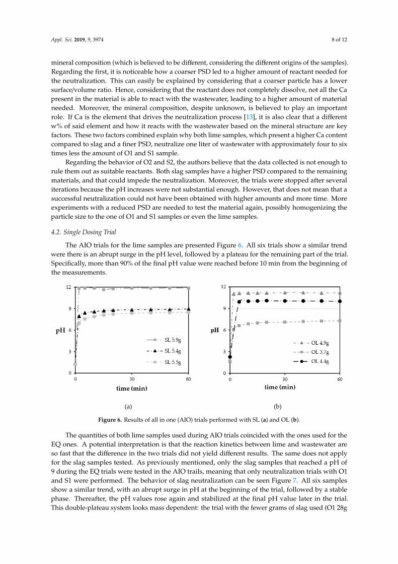
The AIO trials for the lime samples are presented Figure 6. All six trials show a similar trendwere there is an abrupt surge in the pH level, followed by a plateau for the remaining part of the trial.Specifically, more than 90% of the final pH value were reached before 10 min from the beginning ofthe measurements.
Appl. Sci. 2019, 9, x FOR PEER REVIEW 9 of 13
(a) (b)
Figure 6. Results of all in one (AIO) trials performed with SL (a) and OL (b).
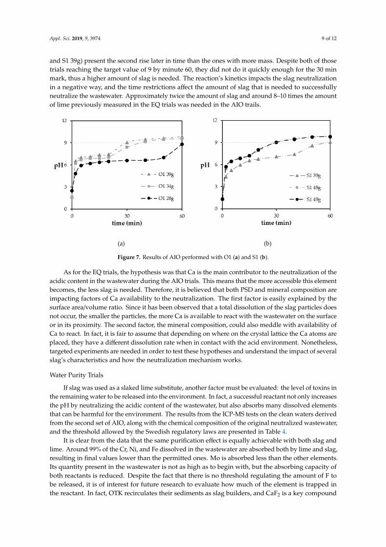
The quantities of both lime samples used during AIO trials coincided with the ones used for the EQ ones. A potential interpretation is that the reaction kinetics between lime and wastewater are so fast that the difference in the two trials did not yield different results. The same does not apply for the slag samples tested. As previously mentioned, only the slag samples that reached a pH of 9 during the EQ trials were tested in the AIO trails, meaning that only neutralization trials with O1 and S1 were performed. The behavior of slag neutralization can be seen Figure 7. All six samples show a similar trend, with an abrupt surge in pH at the beginning of the trial, followed by a stable phase. Thereafter, the pH values rose again and stabilized at the final pH value later in the trial. This double-plateau system looks mass dependent: the trial with the fewer grams of slag used (O1 28g and S1 39g) present the second rise later in time than the ones with more mass. Despite both of those trials reaching the target value of 9 by minute 60, they did not do it quickly enough for the 30 min mark, thus a higher amount of slag is needed. The reaction’s kinetics impacts the slag neutralization in a negative way, and the time restrictions affect the amount of slag that is needed to successfully neutralize the wastewater. Approximately twice the amount of slag and around 8–10 times the amount of lime previously measured in the EQ trials was needed in the AIO trails.
(a) (b)
Figure 7. Results of AIO performed with O1 (a) and S1 (b).
Figure 6. Results of all in one (AIO) trials performed with SL (a) and OL (b).
The quantities of both lime samples used during AIO trials coincided with the ones used for theEQ ones. A potential interpretation is that the reaction kinetics between lime and wastewater areso fast that the difference in the two trials did not yield different results. The same does not applyfor the slag samples tested. As previously mentioned, only the slag samples that reached a pH of9 during the EQ trials were tested in the AIO trails, meaning that only neutralization trials with O1and S1 were performed. The behavior of slag neutralization can be seen Figure 7. All six samplesshow a similar trend, with an abrupt surge in pH at the beginning of the trial, followed by a stablephase. Thereafter, the pH values rose again and stabilized at the final pH value later in the trial.This double-plateau system looks mass dependent: the trial with the fewer grams of slag used (O1 28g
Appl. Sci. 2019, 9, 3974 9 of 12
and S1 39g) present the second rise later in time than the ones with more mass. Despite both of thosetrials reaching the target value of 9 by minute 60, they did not do it quickly enough for the 30 minmark, thus a higher amount of slag is needed. The reaction’s kinetics impacts the slag neutralizationin a negative way, and the time restrictions affect the amount of slag that is needed to successfullyneutralize the wastewater. Approximately twice the amount of slag and around 8–10 times the amountof lime previously measured in the EQ trials was needed in the AIO trails.
Appl. Sci. 2019, 9, x FOR PEER REVIEW 9 of 13
(a) (b)
Figure 6. Results of all in one (AIO) trials performed with SL (a) and OL (b).
The quantities of both lime samples used during AIO trials coincided with the ones used for the EQ ones. A potential interpretation is that the reaction kinetics between lime and wastewater are so fast that the difference in the two trials did not yield different results. The same does not apply for the slag samples tested. As previously mentioned, only the slag samples that reached a pH of 9 during the EQ trials were tested in the AIO trails, meaning that only neutralization trials with O1 and S1 were performed. The behavior of slag neutralization can be seen Figure 7. All six samples show a similar trend, with an abrupt surge in pH at the beginning of the trial, followed by a stable phase. Thereafter, the pH values rose again and stabilized at the final pH value later in the trial. This double-plateau system looks mass dependent: the trial with the fewer grams of slag used (O1 28g and S1 39g) present the second rise later in time than the ones with more mass. Despite both of those trials reaching the target value of 9 by minute 60, they did not do it quickly enough for the 30 min mark, thus a higher amount of slag is needed. The reaction’s kinetics impacts the slag neutralization in a negative way, and the time restrictions affect the amount of slag that is needed to successfully neutralize the wastewater. Approximately twice the amount of slag and around 8–10 times the amount of lime previously measured in the EQ trials was needed in the AIO trails.
(a) (b)
Figure 7. Results of AIO performed with O1 (a) and S1 (b). Figure 7. Results of AIO performed with O1 (a) and S1 (b).
As for the EQ trials, the hypothesis was that Ca is the main contributor to the neutralization of theacidic content in the wastewater during the AIO trials. This means that the more accessible this elementbecomes, the less slag is needed. Therefore, it is believed that both PSD and mineral composition areimpacting factors of Ca availability to the neutralization. The first factor is easily explained by thesurface area/volume ratio. Since it has been observed that a total dissolution of the slag particles doesnot occur, the smaller the particles, the more Ca is available to react with the wastewater on the surfaceor in its proximity. The second factor, the mineral composition, could also meddle with availability ofCa to react. In fact, it is fair to assume that depending on where on the crystal lattice the Ca atoms areplaced, they have a different dissolution rate when in contact with the acid environment. Nonetheless,targeted experiments are needed in order to test these hypotheses and understand the impact of severalslag’s characteristics and how the neutralization mechanism works.
Water Purity Trials
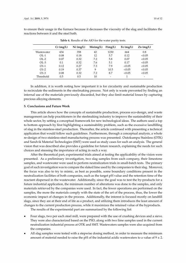
If slag was used as a slaked lime substitute, another factor must be evaluated: the level of toxins inthe remaining water to be released into the environment. In fact, a successful reactant not only increasesthe pH by neutralizing the acidic content of the wastewater, but also absorbs many dissolved elementsthat can be harmful for the environment. The results from the ICP-MS tests on the clean waters derivedfrom the second set of AIO, along with the chemical composition of the original neutralized wastewater,and the threshold allowed by the Swedish regulatory laws are presented in Table 4.
It is clear from the data that the same purification effect is equally achievable with both slag andlime. Around 99% of the Cr, Ni, and Fe dissolved in the wastewater are absorbed both by lime and slag,resulting in final values lower than the permitted ones. Mo is absorbed less than the other elements.Its quantity present in the wastewater is not as high as to begin with, but the absorbing capacity ofboth reactants is reduced. Despite the fact that there is no threshold regulating the amount of F tobe released, it is of interest for future research to evaluate how much of the element is trapped inthe reactant. In fact, OTK recirculates their sediments as slag builders, and CaF2 is a key compound
Appl. Sci. 2019, 9, 3974 10 of 12
to ensure their usage in the furnace because it decreases the viscosity of the slag and facilitates thereactions between it and the steel bath.
Table 4. Results of the AIO for the water purity tests.
Cr (mg/L) Ni (mg/L) Mo(mg/L) F(mg/L) Fe (mg/L) Zn (mg/L)
Wastewater 434 358 42 1230 664 0.8OL-1 0.08 0.18 12 5.7 0.12 <0.05OL-2 0.07 0.32 7.2 5.8 0.07 <0.05OL-3 0.1 0.32 7.6 5.1 0.17 <0.05O1-1 0.12 0.27 7.3 7.9 <0.05 <0.05O1-2 0.19 0.37 9 10.5 <0.05 <0.05O1-3 0.08 0.32 7.2 8.7 <0.05 <0.05
Threshold 0.5 0.5 10 - 1 -
In addition, it is worth noting how important it is for circularity and sustainable productionto recirculate the sediments in the steelmaking process. Not only is waste prevented by finding aninternal use of the materials previously discarded, but they also limit material losses by capturingprecious alloying elements.
5. Conclusions and Future Work
This article shows how the concepts of sustainable production, process eco-design, and wastemanagement can help practitioners in the steelmaking industry to improve the sustainability of theirwhole sector, by setting a conceptual framework for new technological ideas. The authors used a topto bottom approach by first highlighting a sustainability problem, such as the excessive landfillingof slag in the stainless-steel production. Thereafter, the article continued with presenting a technicalapplication that would follow such guidelines. Furthermore, through a conceptual analysis, a wholere-design of two stainless-steel manufacturing process was presented. Outokumpu Stainless (OTK)and Sandvik Material Technologies (SMT) were used as study cases for such an analysis. The generalvision that was described also provides a guideline for future research, explaining the needs for suchchoices and stressing the importance of acting in such a way.
After the theoretical part, experimental trials aimed at testing the applicability of the vision werepresented. As a preliminary investigation, two slag samples from each company, their limestonesamples, and wastewater were used to perform neutralization trials in small-batch tests. The primarygoal of such investigation was to compare the slaked lime used by the companies to their slag. Moreover,the focus was also to try to mimic, as best as possible, some boundary conditions present in theneutralization facilities of both companies, such as the target pH value and the retention time of thereactant dispersed in the wastewater. Additionally, since the goal was to test the by-products for afuture industrial application, the minimum number of alterations was done to the samples, and onlymaterials retrieved by the companies were used. In fact, the fewer operations are performed on thesamples, the more the materials comply with the state of the art of the process, thus, the lower theeconomic impact of changes in the process. Additionally, the interest is focused mostly on landfillslags, since they are at their end of life as a product, and utilizing them introduces the least amount ofchanges to the current production process, while it maximizes the retained value of the byproducts.
The results of the experimental part are summarized by the following list:
• Four slags, two per each steel mill, were prepared with the use of crushing devices and a sieve.They were also characterized based on the PSD, along with two lime samples used in the currentneutralization industrial process at OTK and SMT. Wastewaters samples were also acquired fromthe companies.
• All slag samples were tested with a stepwise dosing method, in order to measure the minimumamount of material needed to raise the pH of the industrial acidic wastewaters to a value of 9 ± 2.
Appl. Sci. 2019, 9, 3974 11 of 12
Two of them, one per company, raised the pH to the target value. The lime samples were alsotested with the same method for reference. With this method, approximately 4.4 times the amountof slag was needed, compared to the amount of lime.
• The quantities measured during the successful trials in the stepwise dosing trials were used asa benchmark for a second experiment, named single-step dosing. This method differed fromthe previous one in terms of reactant addition, while adding also a timeframe to achieve the pHtarget (9 ± 2 in 30 min), to mimic the industrial neutralization process. Only the slags that weresuccessful in the previous experiments were used for the second one, while lime samples wereonce again used as a reference. The lime quantity needed to successfully raise the pH of thewastewaters did not change compared to the stepwise dosing method, while the quantities ofslag were not sufficient to reach the target within the time limit; thus, more material was needed.This has been attributed to a slower kinetics for the reaction with slag compared to the one withlime. With this method, around eight times the amount of slag was needed compared to lime.
• The chemical composition of the clean waters produced after single-step dosing trials, obtainedwith the OTK slag sample, was measured with ICP-MS analysis and compared to the originalcomposition of the OTK wastewaters, also measured with the same method. The concentrationsof six elements (Cr, Ni, Mo, F, Fe, and Zn) were measured and compared. The same procedurewas used for clean waters produced with lime single-step dosing trials, as a reference. The slagsample proved capable of purifying the wastewaters to levels comparable to lime, and both thereactants managed to absorb the tested elements, reducing their concentrations in the watersbelow the legally permitted threshold values.
The results of the trials performed, despite applied at a laboratory scale, thus, far from theindustrial case, provided solid evidence that the vision drafted has a strong practical counterpart.After seeing the results of these preliminary tests, it is believed that slag should be tested thoroughly,both from an applied point of view, by closing the gap between industrial and laboratory conditions,and from a theoretical point of view analyzing the neutralization mechanism and what parameters canbe modified to increase the neutralization efficiency. The two slags that could not reach the target pHvalue should not be excluded from the list of possible reactants, but more experiments with a finer andmore homogenized PSD distribution across all the samples are needed to have a definite answer. Oncesingle-step dosing trials are re-done, the samples used should be analyzed through XRD and SEM,to provide their complete characterization. Once the mineral content is characterized, it is possible tocorrelate it with the neutralization efficiency of the samples with a homogenous PSD. ICP-MS analysison the slag samples was deemed unfit to the scope, because the mineral structure is not taken intoaccount by this type of analysis, since it only measures the pure chemical composition. In particular,focusing only on the total amount of Ca present in the slag sample without considering how it is boundto other elements is not sufficient to draw any conclusions.
This paper analyzes and presents experiments done via the route represented on the left-hand sideof Figure 4, since it presents the first obstacle to achieving a zero-waste EAF process, even though moreexperiments need to be done on the second path, which revolves around the re-use of the saturated slagin the steelmaking process. First, it is important to understand their mineral composition; therefore,XRD and SEM are once again needed for a complete characterization. If the sediments will be used forhigh-temperature processes above their melting point, for instance as slag builders, then an ICP-MSmay be sufficient. Saturated lime (since it is rich in CaF2 after the neutralization) has already been usedas a slag builder by OTK, and the authors believe similar applications can be applied for saturated slagas well, hence the reason why F removal was tested in the water purity trials. Even though it is onlypossible to address a possible use for the sediments by first understanding the mineral content, it isalso not difficult to imagine that closing the loop of slag generates difficulties, as well as opening upmany questions regarding the degradation of the material over time and how it can impact the processand the steel quality.
Appl. Sci. 2019, 9, 3974 12 of 12
To conclude, rather than providing a full overview of a process change, this paper aims tobe the stepping stone towards the adoption of a new technology that could start the transitiontowards a zero-waste production of stainless-steel. The experimental trials presented are only the firstinvestigation of many to come to provide the industry and the research community with comprehensiveanswers regarding this new approach to slag valorization.
Author Contributions: Conceptualization, A.G., M.D.C. and P.J.; methodology, A.G. and M.D.C.; validation,M.D.C. P.J., A.K. and A.G.; investigation, M.D.C., P.J., A.G. and A.K.; resources, P.J.; writing—original draftpreparation, M.D.C., P.J., A.G. and A.K.; writing—review and editing, A.R., G.R.; supervision, P.J., A.G. and A.K.;project administration, P.J.; funding acquisition, P.J.
Funding: This research received no external funding.
Conflicts of Interest: The authors declare no conflict of interest.
References
1. Crutzen, P.J. Geology of mankind The Anthropocene. Nature 2002, 415, 22–23. [CrossRef] [PubMed]2. Rockström, J.; Steffen, W.; Noone, K.; Persson, Å.; Chapin, F.S.I.I.I.; Lambin, E.; Lenton, T.M.; Scheffer, M.;
Folke, C.; Schellnhuber, H.J.; et al. Planetary Boundaries: Exploring the Safe Operating Space for Humanity.Ecol. Soc. 2009, 14, 32. [CrossRef]
3. Hultman, J.; Corvellec, H. The European Waste Hierarchy: From the Sociomateriality of Waste to a Politics ofConsumption. Environ. Plan. Econ. Space 2012, 44, 2413–2427. [CrossRef]
4. Lansink, A. Challenging Changes–Connecting Waste Hierarchy and Circular Economy. Waste Manag. Res.2018, 36, 872. [CrossRef]
5. Van Ewijk, S.; Stegemann, J.A. Limitations of the waste hierarchy for achieving absolute reductions inmaterial throughput. J. Clean. Prod. 2016, 132, 122–128. [CrossRef]
6. Pålsson, K.; Sweden, O.; Stemne, J.; Ruist, G.; Blixt, E. Stålindustrin Gör Mer än Stål. Handbok för Restprodukter2018; Jernkontoret: Stockholm, Sweden, 2018.
7. Geiseler, J. Use of Steelwork Slag in Europe. Waste Manag. 1996, 16, 59–63. [CrossRef]8. Autelitano, F.; Giuliani, F. Electric arc furnace slags in cement-treated materials for road construction:
Mechanical and durability properties. Constr. Build. Mater. 2016, 113, 280–289. [CrossRef]9. Engström, F.; Larsson, M.L.; Samuelsson, C.; Sandström, Å.; Robinson, R.; Björkman, B. Leaching Behavior
of Aged Steel Slags. Steel Res. Int. 2014, 85, 607–615. [CrossRef]10. Santoro, L.; Volpicelli, G.; Caprio, V. Limestone neutralization of acid waters in the presence of surface
precipitates. Water Res. 1987, 21, 641–647. [CrossRef]11. Foxon, T.J. Technological Lock-In. In Encyclopedia of Energy, Natural Resource, and Environmental Economics;
Elsevier: Amsterdam, The Netherlands, 2013; pp. 123–127.12. Fogelström, J.B.; Pousette, H. Neutralizing Acidic Wastewater From the Pickling Process Using Slag from the
Steelmaking Process. Master’s Thesis, KTH Royal Institute of Technology, Stockholm, Sweden, 2017.13. Yang, H.F.; Ou, Q.F.; Zhou, F. Steel Slag as Neutralization-Adsorption Material for Treatment of Acidic
Zn2+-Containing Wastewater. Adv. Mater. Res. 2012, 383, 3416–3421.
© 2019 by the authors. Licensee MDPI, Basel, Switzerland. This article is an open accessarticle distributed under the terms and conditions of the Creative Commons Attribution(CC BY) license (http://creativecommons.org/licenses/by/4.0/).
Copyright © 2022 FDOKUMEN