Supporting Information - MPG.PuRe
22
© 2021 Wiley-VCH GmbH Supporting Information for Adv. Mater., DOI: 10.1002/adma.202006723 A Novel Soft-Magnetic B2-Based Multiprincipal-Element Alloy with a Uniform Distribution of Coherent Body- Centered-Cubic Nanoprecipitates Yue Ma, Qing Wang,* Xuyang Zhou, Jiamiao Hao, Baptiste Gault, Qingyu Zhang, Chuang Dong, and T. G. Nieh*
-
Upload
khangminh22 -
Category
Documents
-
view
6 -
download
0
Transcript of Supporting Information - MPG.PuRe

© 2021 Wiley-VCH GmbH
Supporting Information
for Adv. Mater., DOI: 10.1002/adma.202006723
A Novel Soft-Magnetic B2-Based Multiprincipal-ElementAlloy with a Uniform Distribution of Coherent Body-Centered-Cubic Nanoprecipitates
Yue Ma, Qing Wang,* Xuyang Zhou, Jiamiao Hao,Baptiste Gault, Qingyu Zhang, Chuang Dong, and T. G.Nieh*

1
Copyright Wiley-VCH GmbH, 2021.
Supporting Information
A Novel Soft-Magnetic B2-Based Multi-Principal-Element Alloy with a Uniform
Distribution of Coherent Body-Centered-Cubic Nanoprecipitates
Yue Ma1, Qing Wang,1,* Xuyang Zhou2, Jiamiao Hao1, Baptiste Gault2,3, Qingyu Zhang4,
Chuang Dong1, T.G. Nieh5,*
[1] Key Laboratory of Materials Modification by Laser, Ion and Electron Beams (Ministry of
Education), School of Materials Science and Engineering, Dalian University of Technology,
Dalian 116024, China [2] Max-Planck-Institut für Eisenforschung, Max-Planck-Straße 1, Düsseldorf 40237,
Germany [3] Department of Materials, Royal School of Mines, Imperial College, London, SW7 2AZ,
United Kingdom [4] School of Physics, Dalian University of Technology, Dalian 116024, China [5] Department of Materials Science and Engineering, University of Tennessee, Knoxville,
Tennessee 37996, USA
E-mail addresses: [email protected] (Q. Wang), [email protected] (T. G. Nieh)

2
Sample preparation
The designed Al1.5Co4Fe2Cr (Al17.65Co47.06Fe23.53Cr11.76, at. %) alloy was prepared by means of
arc melting and suction cast into a copper mold with dimension of 2 mm-thick and 9 mm-wide
plates under an argon atmosphere. Purities of the raw metals are 99.99 % for Al, Co, and Fe,
and 99.9 % for Cr. Mixtures of raw materials with the nominal composition and a total weight
of about 6 g were remelted at least five times to obtain high-quality specimens. These as-cast
Al1.5Co4Fe2Cr alloy plates were homogenized at 1573 K for 2 h, and then aged at 773 K, 873
K, 973 K, and 1073 K for 24 h, designated as A-773, A-873, A-973, and A-1073, respectively.
In addition, the A-773 specimens were also heat-treated at 873 K for different times of 8 h, 70
h, 305 h and 555 h, in order to study the thermal stability of the soft-magnetic properties. Each
treatment was followed by water-quenching.
Calculation of lattice misfit
The lattice misfit between the BCC and B2 phases in A-773 alloy was calculated according to
the formula of = 2(aB2-aBCC)/(aB2+aBCC),[S1] in which aB2 and aBCC are the lattice constants of
B2 and BCC phases, respectively. In addition, the crystal structure of A-773 was identified
using a Bruker D8 X-ray diffractometer (XRD) with the Cu K radiation ( = 0.15406 nm), and
the external standard method was applied to calculate the lattice constants.[S2]
APT analysis
The chemical information was investigated using atom probe tomography (APT) at the near-
atomic scale. The required needle-shaped geometry for APT specimens was prepared using a
focus ion beam (FIB) lift-out and annular milling technique in a FEI Helios Nanolab 600i.[S3]
The specimens were field analyzed in a Cameca Instruments Local Electrode Atom Probe
(LEAP) 5000 HR operated at a specimen setpoint temperature of 50 K and laser pulse energy
of 5 pJ at a pulse repetition rate of 200 kHz for a 0.5 % atoms per pulse detection rate. The APT
data were reconstructed using the IVAS 3.8.4 software platform, and the reconstruction has
been calibrated based on the methodology described in Ref. [S4]. In Figure 1f, we overlaid sets

3
of 35 at. % Cr and 33 at. % Fe iso-composition surfaces on top of the point cloud to highlight
the elemental distributions around Cr clusters.
Statistics on particle size of nanoprecipitates
Image analysis of the microstructural details were made in the ImageJ software.[S5] Statistical
analysis on the size of BCC precipitated particles was performed with at least 6 TEM
morphology images. The particle size was obtained from over 150 particles, and defined using
an area-equivalent diameter (i.e., 𝑟 = 2√𝑎𝑟𝑒𝑎/𝜋). In addition, the standard error (SE) in r
was obtained using 𝑆𝐸 = 𝜎/√𝑁, where is the standard deviation of particle sizes, and N is
the number of precipitates.
Calculation of the mean magnetic moment per atom 𝝁𝑯
The saturation induction intension BS depends on the content in the ferromagnetic elements of
Fe, Co and Ni.[S6] If we consider only the change in ferromagnetic element content, the mean
magnetic moment per atom 𝜇𝐻 can be expressed as
𝜇𝐻 = ∑ 𝜇𝐻,𝑖 ∙ 𝑥𝑖 (S1)
where H,i is the experimental magnetic moment per atom, i.e., ,Fe=2.2, ,Co=1.7, and
,Ni =0.6 (, Bohr magneton),[S6] and xi is the atomic concentration of Fe, Co, and Ni
elements.
The Cluster formula approach for Composition Design
In our previous work, we proposed a ‘cluster-plus-glue-atom’ structural model to describe the
local atomic distribution of alloying elements based on the chemical short-range orders
(CSROs).[S7-S10] The CSROs are the most typical structural characteristics of solid solutions due
to the obvious local structural heterogeneities with respect to the average crystal structure,
which plays an important role to the diverse mechanical and physical properties of alloys.[S11-
S15] In this cluster model, the cluster is the nearest-neighbor polyhedron centered by a solute
atom who has the strong interaction with the base solvent atoms to represent the strongest

4
CSRO. Some other solute atoms (i.e., glue atoms) with weak interactions are certainly required
to fill the space between the clusters to balance the atomic-packing density. Thus, a uniform
composition formula [cluster](glue atom)x (x being the glue atom number) can be obtained from
the cluster model, named the cluster formula approach.[S7-S9] The sites of the solute elements in
the cluster formula is determined according to the enthalpy of the mixing (ΔH) between the
solute and the base element that represents the interaction between them.[S16] That is to say, the
solute element having a large negative ΔH with the base preferentially occupies the cluster
center site to form a stable cluster, while that with a positive ΔH tends to occupy the glue atom
site. Besides, the cluster-shell sites are primarily occupied by the base solvent atoms, as well as
some solutes having a zero ΔH with the base. So the cluster formula [cluster](glue atom)x,
containing all the key information on the alloy chemistry, i.e., chemical compositions, atomic
occupancies (at the center, shell and glue sites) and chemical bonds in a cluster structural unit,
can be regarded as the molecular formula for alloy structure. Particularly, in the BCC structure,
the nearest-neighbor cluster is the rhombi-dodecahedron with a coordination number (CN) of
14 (the 1st-shell CN8 + 2nd-shell CN6), and the glue atom number x was ideally calculated as x
= 1, 2, or 3.[S8] Since the multi-principal-element alloys (MPEAs), also named the high entropy
alloys (HEAs), can be treated as a special kind of solid solution alloys, CSROs have been
confirmed in some HEAs by both neutron scattering experiments and simulations.[S17, S18] Thus,
we applied the cluster formula approach into the HEA-forming systems for composition design
to tailor their microstructures.[S19]
For instance, we used a cluster formula of [Al-M14]Al1 (M represents different combinations of
Co, Cr, Fe, and Ni) to design a series of Al-Co-Cr-Fe-Ni HEAs, which exhibit special coherent
microstructure with ordered B2 nanoprecipitates dispersed into the BCC solid solution
matrix.[S10, S19, S20] Especially, the precipitation of cuboidal B2 nanoparticles in the BCC matrix
render these HEAs with higher yield strength (1.7 ~ 2.2 GPa) and better microstructural stability
at high temperatures.[S20] In addition, the B2 nanoprecipitates are enriched by Al and Ni, while

5
Fe, Co and Cr are segregated preferentially in the BCC matrix.[S19] The cluster formula of the
current Al1.5Co4Fe2Cr alloy will be described in the following section.
Design strategy of soft-magnetic alloys with coherent nanoprecipitates
The magnetic property of materials is closely related to the magnetic domains, in which the
internal stress induced by crystalline defects can block the movement of domain walls in an
applied magnetic field, resulting in an increase in the total energy of system.[S21-S23] When the
domain wall moves to a certain position of x, the domain wall energy Ew will increase, but the
magnetostatic energy EH will decrease in order to achieve the energy minimum. In other words,
EH and Ew offset each other and we have Equation S2:[S21-S23]
𝜕𝐸𝐻
𝜕𝑥+
𝜕𝐸𝑤
𝜕𝑥= 0 (S2)
𝐸𝐻 = −2𝜇0𝐻𝐶𝑀𝑆𝑥 cos 𝜃 (S2a)
𝐸𝑤 = 2√𝐴/ [𝐾1 +3
2𝜆𝑠𝜎(𝑥)] = 2 ∙ 𝛿 (S2b)
where 0 is the permeability of vacuum, is the angle between the magnetic moment and the
magnetic field direction after the movement of domain wall, A is a constant, K1 is the magnetic
anisotropy constant, s is the magnetostriction coefficient, (x) is the internal stress field caused
by the various crystalline defects (especially the boundaries of grains and ultrafine precipitates)
that is related to the position x, and is the width of the domain wall.[S21-S23] Apparently, the
coercivity HC is associated to the internal stress (x). Since the (x) is a wave function with a
characteristic wavelength l, the coercivity HC could be calculated through Equation S3: [S21-S23]
𝐻𝐶 =𝜆𝑠∆𝜎
2𝜇0𝑀𝑆 cos 𝜃
3𝛿/𝑙
1+3(𝛿/𝑙)2 (S3)

6
where is the amplitude of internal stress wave. Thus, the coercivity HC depends on a series
of parameters, s, MS, , , and l. Especially, the characteristic wavelength l is crucial for
achieving a low HC since it is related to the grain size Dg of materials that could be tuned through
material processing. For instance, when the l is much larger than the width of domain wall
(i.e., l >> ), the coercivity HC of Mn-Zn soft ferrite could reach a minimum of HC = 6.4 A/m
at a grain size Dg > 5 m, in which the ratio of / l is dominant.[S21] On the other extreme, if the
l is effectively reduced such that l << , like in materials containing ultrafine ferromagnetic
nanoprecipitates, a low HC could also be obtained in light of Equation S3 due to the dominant
term of ( / l)2.
From Equation S3, it can be seen that a low HC can also be obtained by increasing the saturation
magnetization MS, which can be obtained in BCC structure rather than FCC. For example, it
has been demonstrated that magnetic exchange interactions from nearest-neighbor atomic pairs
of Fe-Fe, Fe-Co, and Co-Co could give the maximum contribution to a high MS in Fe-Co-Cr-
Ni-Al HEAs, and these interactions in the BCC structure are stronger than those in the FCC due
to different chemical short-range orders (CSROs).[S24] In addition, the effects of s and on HC
could be negligible, except in the presence of oriented texture.[S23] Therefore, it is possible to
obtain high-performance soft-magnetic alloys through tuning the microstructure to contain
ultrafine BCC ferromagnetic nanoprecipitates in a B2 matrix.
However, to get a special coherent microstructure with ultrafine BCC ferromagnetic
nanoprecipitates in a B2 matrix is still challenging since it is susceptible to the compositional
difference between BCC and B2 phases. A weave-like or plate-like spinodal decomposition
microstructure of BCC and B2 was always observed in these HEAs due to a large composition
difference between them.[S25-S28] Intensive efforts have been made to explore the possibility to
precipitate spherical or cuboidal particles in a large variety of BCC-related alloy systems
through adjusting the concentrations of both Al and transition metals.[S19, S20, S29-S31] It is known

7
that the main driving force for the growth of coherent particles is the elastic energy, which is
determined by the lattice misfit strain, between the precipitated phase and the matrix.[S32-S35]
Small spherical nanoprecipitates are generally observed at a relatively small (< 0.2 %) in Al-
Ni-Co-Fe-Cr HEAs.[S19] Thus, it is necessary to deliberately tune the compositions of BCC and
B2 phases simultaneously to minimize the in order to achieve a unique coherent
microstructure which has a uniform distribution of ferromagnetic BCC nanoprecipitates in the
B2 matrix.
Among the ferromagnetic elements Fe, Co, and Ni, the magnetic moment of Ni is much less
than that of Fe or Co (,Fe = 2.2, ,Co = 1.7, and ,Ni = 0.6.).[S6] Therefore, to
maximize the magnetic moment and the saturation magnetization MS, Ni should be removed to
ensure that the BCC nanoprecipitate is enriched with more Co and Fe. The Al element is crucial
to form the FeAl and CoAl B2 phases in Al-Co-Fe-Cr system.[S36] And the content of Al must
higher than that in previous [Al-M14]Al1 alloys in order to realize the phase inversion, i.e., the
BCC nanoparticles are precipitated in the B2 matrix. Therefore, another cluster formula with
the glue atom number of x = 2 will be applied in the present work to design alloy compositions
of [Al-M14]Al2. Another important note is that BCC and B2 often form a weave-like
microstructure, instead of a desirable particle precipitation in Co-Fe-Ni-Al-based magnetic
alloys.[S37] This feature has been attributed to a larger lattice misfit caused by a large
compositional difference between BCC and B2. In order to minimize the lattice misfit for
bypassing the formation of weave-like microstructure, Cr was introduced to reduce the lattice
misfit for producing spherical nanoprecipitates. Taken into account of all these considerations,
M in the cluster formula is composed of Co, Fe, and Cr, in which Co occupies preferentially
the 1st-shell sites with CN8 due to the relatively-strong interactions with Al (HAl-Co = -19
kJ·mol-1),[S16] and Fe and Cr occupies the 2nd-shell sites of CN6 (HAl-Fe = -11 kJ·mol-1, and
HAl-Cr = -10 kJ·mol-1)[S16] with a ratio of Fe/Cr = 2/1 due to the ferromagnetism of Fe.

8
Accounting for all these considerations, the [Al-(Co8Fe4Cr2)]Al2 cluster formula
(Al1.5Co4Fe2Cr, Al17.65Co47.06Fe23.53Cr11.76, at. %) was finally designed to obtain the coherent
microstructure with BCC nanoprecipitates (Fe, Co, and Cr-rich) in the B2 matrix (Al and Co-
rich).

9
Figure S1. XRD pattern of the Al1.5Co4Fe2Cr alloy after aging at 773 K for 24 h (A-773),
consisting of BCC and B2 phases. The lattice constants of these two phases are aBCC = 0.2897
nm and aB2 = 0.2900 nm, respectively.
20 30 40 50 60 70 80
• BCC B2
(200)/
(200)
(100)
(110)/
(110)
•
2 deg.
Inte
nsit
y,
a.u
.
•
10
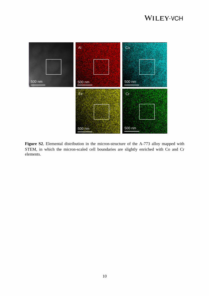
Figure S2. Elemental distribution in the micron-structure of the A-773 alloy mapped with
STEM, in which the micron-scaled cell boundaries are slightly enriched with Co and Cr
elements.
500 nm 500 nm
500 nm
500 nm
500 nm
Al Co
Fe Cr

11
Figure S3. (a) TEM bright-field (BF) image of the A-873 specimen, (b) SEM image of the A-
973 specimen, (c) SEM image of the A-1073 specimen.
100 nm
(a)
500 nm
(b)
(c)
500 nm

12
Figure S4. SEM and TEM images of 555 h-aged specimen at 873 K. (a) SEM image; (b) TEM-
DF image and the corresponding SEAD pattern, showing that the uniform BCC particles are
coherently embedded in B2 matrix; (c) HRTEM image of B2 matrix and BCC particle, in which
the FFT patterns obtained from the B2 matrix (c-1) and BCC particle (c-2) are also given.
100 nm
(a)
[100]B2
[100]BCC
(c-1)
(c-2) BCC particle
(c)
B2 matrix
5 nm
200 nm
(b)
[100]BCC[100]B2
cc
(011)BCC
c
(011)BCC
cc (001)B2
c
(010)B2

13
Figure S5. Elemental distributions in 873 K-aged specimen for 555 h obtained with the FIB-
EDS. (a) Elemental mapping, showing that the BCC nanoparticles are enriched with Cr and the
B2 matrix is enriched with Al and Co; (b) Linear-scanning analysis from the red line in (a),
indicating that Fe is enriched around the Cr-cores to form core-shell strucutred BCC
nanoparticles, rather than enriched in the B2 matrix alone, as evidenced by the yellow and green
dotted lines. Obviously, the Al-rich regions (marked with red dotted lines) correspond to the
Cr-poor regions. The basic Co element is uniformly distributed in the Cr-poor regions.
0 20 40 60 80 100 120
Cr
Fe
Co
Al
d nm
Inte
nsity,
a.u
.
Cr
100 nm
100 nm
Al Co
100 nm
Fe
100 nm
(a)
(b)

14
Figure S6. (a) Hysteresis loops of S1-S3 HEAs. TEM dark-field (DF) images and the
corresponding selected-area electron diffraction (SAED) patterns of S1 and S2 alloys, as well
as the OM and SEM images of S3 alloy are shown in (b), (c) and (d), respectively.
-1000000 -500000 0 500000 1000000
-60
-40
-20
0
20
40
60
S1
S2
S3
Ma
gn
eti
za
tio
n (
em
u/g
)
Magnetic field (A/m)
-5000 -2500 0 2500 5000-0.2
0.0
0.2
Mag
neti
zati
on
(em
u/g
)Magnetic field (A/m)
[100]BCC[100]B2
(011)
(020) (001)
(010)
B2
BCC
(c) S2
(a)
B2
BCC (112)
(002)
(001)
(111)
(b) S1
BCC/B2
1 m BCC/B2
FCC
20 m
(d) S3

15
Table S1. Magnetic properties of the current Al1.5Co4Fe2Cr (Al17.65Co47.06Fe23.53Cr11.76, at. %)
alloy heat-treated at different temperatures, including the saturation magnetization (MS),
saturation induction intension (BS), and coercivity (HC).
Treatment Ms
(emu/g) Bs a) (T)
Hc
(Oe) (A/m)
A-773 1573K/2h+773K/24h 135.3 1.3 1.6 127.3
A-873 1573K /2h+873K/24h 128.5 1.2 1.4 111.4
A-973 1573K /2h+973K/24h 103.5 1.0 67.6 5379.4
A-1073 1573K /2h+1073K/24h 49.5 0.5 59.7 4750.8
8 h 1573K /2h+773K/24h
+873K/8h 130.9 1.2 1.4 111.4
70 h 1573K /2h+773K/24h
+873K/70h 130.9 1.2 2.1 167.1
305 h 1573K /2h+773K/24h
+873K/305h 126.3 1.2 2.1 167.1
555 h 1573K /2h+773K/24h
+873K/555h 126.1 1.2 2.7 214.9
a) BS = 4MSm/10000, in which m = 7.36 g/cm3 is the mass density of Al1.5Co4Fe2Cr alloy.

16
Table S2. Data summary of other Al-Ni-Co-Fe-Cr HEAs, including the alloy composition
(at. %), phase constitutions, mass density (m), saturation magnetization (MS), saturation
induction intension (BS), and coercivity (HC).
Alloy composition (at. %) Phase
constitution m
(g/cm3)
Ms
(emu/g)
Bs a)
(T)
Hc
(Oe) (A/m)
S1-
Al0.7NiCoFeCr2 Al12.5Ni17.5Co17.5Fe17.5Cr35
BCC+B2
particles 7.35 28.9 0.3 11.9 947.0
S2-
Al0.86NiCoFeCr Al17.65Ni20.59Co20.59Fe20.59Cr20.59
BCC+B2
(weave-like) 7.24 59.6 0.5 55.0 4376.8
S3-
Al0.57NiCoFeCr Al12.5Ni21.88Co21.88Fe21.88Cr21.88
FCC+BCC/B2
(weave-like) 7.53 11.7 0.1 50.7 4034.6
a) BS = 4MSm/10000.

17
Table S3. Alloy composition (at. %), saturation induction intension (BS), the mean magnetic
moment per atom (𝜇𝐻), and the ratio of 𝑃 = 𝐵𝑠/𝜇𝐻 of typically existing soft-magnetic alloys
and the current Al1.5Co4Fe2Cr alloy.
Alloy composition (at. %) Bs (T) 𝜇
𝐻
(B) P
Al1.5Co4Fe2Cr Al17.65Co47.06Fe23.53Cr11.76 1.3 1.32 0.98
S1 Al12.5Ni17.5Co17.5Fe17.5Cr35 0.3 0.79 0.34
S2 Al17.65Ni20.59Co20.59Fe20.59Cr20.59 0.5 0.93 0.59
S3 Al12.5Ni21.88Co21.88Fe21.88Cr21.88 0.1 0.98 0.11
Finmet alloy [8] Fe73.5Si13.5B9Cu1Nb3 1.2 1.62 0.74
Nanoperm alloy [28] Fe91Zr7B2 1.7 2.00 0.85
Hitperm alloy [6,7] Fe44Co44Zr7B4Cu1 2.0 1.72 1.17
FeCoNi(AlSi)0.1 [16] Fe32.26Co32.26Ni32.26Al1.61Si1.61 1.3 1.45 0.90
FeCoNi(AlSi)0.2 [16] Fe31.25Co31.25Ni31.25Al3.13Si3.13 1.1 1.41 0.78
Al0.5FeCoNi [17] Al14.29Fe28.57Co28.57Ni28.57 0.99 1.29 0.77
Al0.75FeCoNi [17] Al20Fe26.67Co26.67Ni26.67 0.98 1.20 0.82
AlFeCoNi [17] Al25Fe25Co25Ni25 0.85 1.13 0.75
Al0.25FeCoNiMn0.25 [29] Al7.14Fe28.57Co28.57Ni28.57Mn7.14 1.0 1.29 0.78

18
Table S4. Alloy composition (at. %), room-temperature electrical resistivity () and Curie
temperature (TC) of the typically existing typical soft-magnetic alloys and the current
Al1.5Co4Fe2Cr alloy.
Alloy composition (at. %) ( ·cm) TC (K)
Al1.5Co4Fe2Cr Al17.65Co47.06Fe23.53Cr11.76 244 1061
Fe [9,31] Fe 10 1043
3Si-Fe [9,31] Si5.79Fe94.21 45 1013
6.5Si-Fe [9,31] Si12.14Fe87.86 82 973
50Ni-Fe [9,31] Ni48.76Fe51.24 54 773
79Ni-5Mo-Fe [9,31] Ni79.9Mo3.09Fe17.01 60 673
50Co-2V-Fe [9,31] Co48.56V2.25Fe49.19 40 1253
Hitperm alloy [6,7] Fe44Co44Zr7B4Cu1 150 1253
Fe78Si9B13 [32] Fe78Si9B13 137 961
Fe40Ni40P14B6 [32] Fe40Ni40P14B6 180 796
Al0.25FeCoNiMn0.25 [30] Al7.14Fe28.57Co28.57Ni28.57Mn7.14 100 1078

19
References
[S1] W. F. Hosford, Mechanical behavior of materials, Cambridge University Press, New York,
USA 2005.
[S2] D. B. Cullity, S. R. Stock, Elements of X-Ray Diffraction, Prentice Hall, New Jersey, USA
2011.
[S3] K. Thompson, D. Lawrence, D.J. Larson, J. D. Olson, T. F. Kelly, B. Gorman,
Ultramicroscopy 2007, 107, 131.
[S4] B. Gault, M. Moody, F. D. Geuser, G. Tsafnat, A. L. Fontaine, L. Stephenson, D. Haley,
S. Ringer, J. Appl. Phys. 2009, 105, 772.
[S5] C. A. Schneider, W. S. Rasband, K. W. Eliceiri, Nat. Methods 2012, 9, 671.
[S6] B. D. Cullity, C. D. Graham, Introduction to magnetic materials, Addison Wesley, Boston,
USA 1972.
[S7] C. Dong, Q. Wang, J. B. Qiang, Y. M. Wang, N. Jiang, G. Han, Y. H. Li, J. Wu, J. H. Xia,
J. Phys. D: Appl. Phys. 2007, 40, R273.
[S8] C. Pang, B. B. Jiang, Y. Shi, Q. Wang, C. Dong, J. Alloy. Compd. 2015, 652, 63.
[S9] Z. R. Wang, J. B. Qiang, Y. M. Wang, Q. Wang, D. D. Dong, C. Dong, Acta Mater. 2016,
111, 366.
[S10] Y. Ma, Q. Wang, C. L. Li, L. J. Santodonato, M. Feygenson, C. Dong, P. K. Liaw, Scripta
Mater. 2018, 144, 64.
[S11] I. Mirebeau, M. Hennion, G. Parette, Phys. Rev. Lett. 1984, 53, 687.
[S12] J. M. Cowley, Phys. Rev. 1950, 77, 669.
[S13] P. Singh, A. V. Smirnov, D. D. Johnson, Phys. Rev. B 2015, 91, 224204.
[S14] R. C. Brouwer, R. Griessen, Phys. Rev. B 1989, 40, 1481.
[S15] H. W. Sheng, W. K. Luo, F. M. Alamgir, J. M. Bai, E. Ma, Nature 2006, 439, 419.
[S16] A. Takeuchi, A. Inoue, Mater. Trans. 2005, 46, 2817.

20
[S17] W. Guo, W. Dmowski, J. Y. Noh, P. Rack, P. K. Liaw, T. Egami, Metall. Mater. Trans.
A 2013, 44, 1994.
[S18] M. C. Gao, D. E. Alman, Entropy 2013, 15, 4504.
[S19] Y. Ma, Q. Wang, B. B. Jiang, C. L. Li, J. M. Hao, X. N. Li, C. Dong, T. G. Nieh, Acta
Mater. 2018, 147, 213.
[S20] Y. Ma, J. M. Hao, Q. Wang, C. Zhang, C. L. Li, C. Dong, J. Mater. Sci. 2019, 54, 8696.
[S21] G. Herzer, in Handbook of magnetic materials, Vol. 10 (Ed: K. H. J. Buschow), Elsevier
Science BV, Amsterdam, the Netherlands, 1997.
[S22] W. D. Zhong, Ferro magnetics, Science Press, Beijing, China 1987.
[S23] F. E. Luborsky, J. D. Livingston, G. Y. CHIN, in Physical Metallurgy, Vol. 3 (Eds: R.
W. Cahn, P. Haasen), Elsevier Science BV, Amsterdam, the Netherlands, 1996, Ch. 29.
[S24] S. Huang, W. Li, X. Q. Li, S. Schönecker, L. Bergqvist, E. Holmström, L. K. Varga, L.
Vitos, Mater. Des. 2016, 103, 71.
[S25] L. J. Santodonato, Y. Zhang, M. Feygenson, C. M. Parish, M. C. Gao, R. J. Weber, J. C.
Neuefeind, Z. Tang, P. K. Liaw, Nat. Commun. 2015, 6, 5964.
[S26] Y. P. Wang, B. S. Li, M. X. Ren, C. Yang, H. Z. Fu, Mater Sci. Eng. A 2008, 491, 154.
[S27] Y. F. Kao, T. J. Chen, S. K. Chen, J. W. Yeh, J. Alloys Compd. 2009, 488, 57.
[S28] Y. Ma, B. B. Jiang, C. L. Li, Q. Wang, C. Dong, P. K. Liaw, F. Xu, L. Sun, Metals 2017,
7, 57.
[S29] C. L. Li, Y. Ma, J. M. Hao, Y. Yan, Q. Wang, C. Dong, P. K. Liaw, Mater. Sci. Eng. A
2018, 737, 286.
[S30] O. N. Senkov, S. V. Senkova, C. Woodward, Acta Mater. 2014, 68, 214.
[S31] S. Z. Niu, H. C. Kou, T. Guo, Y. Zhang, J. Wang, J. S. Li, Mater. Sci. Eng. A 2016, 671,
82.
[S32] P. W. Voorhees, G. B. Mcfadden, W. C. Johnson, Acta Metall. Mater. 1992, 40, 2979.
[S33] P. Fratzl, O. Penrose, J. L. Lebowitz, J. Stat. Phy. 1999, 95, 1429.

21
[S34] M. E. Thompson, C. S. Su, P. W. Voorhees, Acta Metall. Mater. 1994, 42, 2107.
[S35] E. A. Marquis, D. N. Seidman, Acta Mater. 2011, 49, 1909.
[S36] P. Villars, L. D. Calvert, Pearson’s Handbook of Crystallographic Data for Intermetallic
Phases, ASM, Metals Park OH, USA 1985.
[S37] C. Radeloff, I. Pfeiffer, IEEE Transactions on Magnetics 1975, 11, 1417.