
Sub-Project Completi Project Completion Report pletion Report
35
Comp Sub-Proje Design and deve for efficient dri Ma Bangabandhu Sh Project I Banglad mpetitive Research Grant ect Completion Rep on elopment of a compensate ip irrigation system in Ban Project Duration ay 2016toSeptember 2018 heikh Mujibur Rahman Agricultural Univ Gazipur 1706, Bangladesh Submitted to Implementation Unit-BARC, NATP-2 desh Agricultural Research Council Farmgate, Dhaka-1215 September 2018 port ed emitter ngladesh versity Project ID 548
-
Upload
khangminh22 -
Category
Documents
-
view
0 -
download
0
Transcript of Sub-Project Completi Project Completion Report pletion Report

Competitive Research Gran
Sub-Project Completion Report
Design and development of a compensated emitter for efficient drip irrigation system in Bangladesh
May 2016
Bangabandhu Sheikh
Project IBangladesh Agricultural Research Council
Competitive Research Grant
Project Completion Report
on
Design and development of a compensated emitter for efficient drip irrigation system in Bangladesh
Project Duration
May 2016toSeptember 2018
Bangabandhu Sheikh Mujibur Rahman Agricultural UniversityGazipur 1706, Bangladesh
Submitted to
Implementation Unit-BARC, NATP-2 Bangladesh Agricultural Research Council
Farmgate, Dhaka-1215
September 2018
Project Completion Report
Design and development of a compensated emitter for efficient drip irrigation system in Bangladesh
Mujibur Rahman Agricultural University
Project ID 548

Competitive Research Grant (CRG)
Sub-Project Completion Report
Design and development of a compensated emitter for efficient drip irrigation system in Bangladesh
May 2016toSeptember 2018
Bangabandhu Sheikh Mujibur Rahman Agricultural University
Project IBangladesh Agricultural Research Council
Competitive Research Grant (CRG)
Project Completion Report
on
Design and development of a compensated emitter for efficient drip irrigation system in Bangladesh
Project Duration
May 2016toSeptember 2018
Bangabandhu Sheikh Mujibur Rahman Agricultural UniversityGazipur 1706, Bangladesh
Submitted to Implementation Unit-BARC, NATP-2
Bangladesh Agricultural Research Council Farmgate, Dhaka-1215
September 2018
Competitive Research Grant (CRG)
Project Completion Report
Design and development of a compensated emitter for efficient drip irrigation system in Bangladesh
Bangabandhu Sheikh Mujibur Rahman Agricultural University

ii
Citation Design and development of a compensated emitter for efficient drip irrigation system in Bangladesh Project Implementation Unit National Agricultural Technology Program-Phase II Project (NATP-2) Bangladesh Agricultural Research Council (BARC) New Airport Road, Farmgate, Dhaka – 1215 Bangladesh Edited and Published by: Project Implementation Unit National Agricultural Technology Program-Phase II Project (NATP-2) Bangladesh Agricultural Research Council (BARC) New Airport Road, Farmgate, Dhaka – 1215 Bangladesh
Published in: September 2018 Printed by: NATP-II, BARC
Acknowledgement The execution of CRG sub-project has successfully been completed by Bangabandhu Sheikh Mujibur Rahman Agricultural Universityusing the research grant of USAID Trust Fund and GoB through Ministry of Agriculture. The authors would like to thank the World Bank for arranging the grant fund and supervising the CRGs through BARC. It is worthwhile to mention the cooperation and quick responses of PIU-BARC, NATP 2, in respect of field implementation of the sub-project in multiple sites. The authors would also like to acknowledge the assistance of the Agricultural Engineering Unit, NRM Division, BARC for their cooperation during the entire project period. Preparing the project completion report required to contact a number of persons for collection of information and processing of research data. Without the help of those persons, the preparation of this document could not be made possible. All of them, who made it possible, deserve thanks. Our thanks are due to the Director PIU-BARC, NATP 2 and his team who given their whole hearted support to prepare this document. We hope this publication would be helpful to the agricultural scientists of the country for designing their future research projects in order to technology generation as well as increasing production and productivity for sustainable food and nutrition security in Bangladesh. It would also assist the policy makers of the agricultural sub-sectors for setting their future research directions.

iii
Acronyms
ASABE AMERICAN SOCIETY OF AGRICULTURAL AND BIOLOGICAL ENGINEERS
CFD COMPUTATIONAL FLUID DYNAMICS
CRF CAPITAL RECOVERY FACTOR
CV COEFFICIENT OF VARIATION OF FLOW
DI DRIP IRRIGATION
DPIV DIGITAL PARTICLE IMAGE VELOCIMETRY
DU DISTRIBUTION UNIFORMITY
ISO INTERNATIONAL STANDARD ORGANIZATION
ID INSIDE DIAMETER
LDPE LOW DENSITY POLYETHYLENE
OD OUTSIDE DIAMETER
PC PRESSURE COMPENSATING
RNG RENORMALIZATION GROUP
SDI SUBSURFACE DRIP IRRIGATION
SU STATISTICAL UNIFORMITY
SEM SCANNING ELECTRON MICROSCOPY

iv
Table of Contents
Subject Page No. A. Sub-project Description 1
1. Title of the CRG sub-project: 1
2. Implementing organization: 1
3. Principal Investigator 1 4. Sub-project budget (Tk.): 1
5. Duration of the sub-project: 1 6. Justification of undertaking the sub-project: 1
7. Sub-project goal: 2 8. Sub-project objective (s): The objectives of the proposed project are to: 2
9. Implementing location (s): 2
10. Methodology in Brief: 3 10.1 HYDRAULIC DESIGN 3
10.2 PRODUCTION 4 10.3 TESTING 4
10.4 COMMISSIONING AND BUSINESS MODEL 6 11. Results and discussion: 6
11.1 Optimization of Velocity 7
11.2 Manufacturing the emitter 12 11.3 Performance Indices 14
11.4 Field performance indices 15 11.5 Economics of Drip Manufacturing 17
11.6 A Business model exploring forward and backward linkages 11.6.1 Backward Linkages 11.6.2 Forward Linkages
19 20 21
12. Research highlight/findings 21
B. Implementation Position 21 1. Procurement: 21 2. Establishment/renovation facilities: 21
3. Training/study tour/ seminar/workshop/conference organized: 21 C. Financial and physical progress 22
D. Achievement of Sub-project by objectives: (Tangible form) 22 E. Materials Development/Publication made under the Sub-project: 24 F. Technology/Knowledge generation/Policy Support (as applied): 24 G. Information regarding Desk and Field Monitoring 25
i) Desk Monitoring: 25
ii) Field Monitoring: 25 References 27

v
LIST OF FIGURES
Title Page No.
Figure 1. Parameters of the dentate flow path 3
Figure 2. A schematic of the initial design showing the membrane, channels and the orifice. 4
Figure 3. a) The experimental test chamber and, b) Laying out of the laterals 5
Figure 4. Experimental chamber’s a) Feeding sub-main, and b) Receiving sub-main 5
Figure 5 a) Isometric view, and the X-section of the of the Dripper, b) Isometric view of
the fluid domain
6
Figure 6. Velocity fields and the vectors in the labyrinth channel of the emitter 7
Figure 7. Pressure vs. discharge relationship generated from the numerical analysis 7
Figure 8. Velocity profile inside the dripper for inlet pressure of 20 kPa. 8
Figure 9. Dimensional properties of the emitter 10
Figure 10. Dimensional properties of the emitter 11
Figure 11. Emitters printed in a 3D printer according to the design resulted in less
precision of the assembly. Nine-tooth labyrinths were the most affected parts.
12
Figure 12. The mold used to manufacture the newly designed emitter 12
Figure 13 Emitters printed under injection molding 13
Figure 14 Finished product produced from this project under injection molding 13
Figure 15. Head versus discharge relationship of the newly designed emitter 15
Figure 16. Emitters laid out in the field for performance evaluation in an eggplant field. 16
Figure 17. Flow of emitters at different distances from the source of pressure 17
Figure 18. A typical injection molding workpiece at a factory in Nawabpur, Dhaka 18
Figure 19. A sustainable business model for low cost drip manufacturing 20
Figure 20. Actors Involved with DI Technology 20

vi
LIST OF TABLES
Title Page No.
Table 1. Performance indices of the first lot of emitters manufactured under this project. 14
Table 2. Performance indices of the second batch of emitters in the laboratory hydraulic experiment.
15
Table 3. In-field performance indices of the newly developed emitters. 16
Table 4. Cost items involved in a drip manufacturing business 19

vii
Executive Summary
The project aims to design and develop a pressure compensated online type emitter using low cost plastic emitter. Therefore, it was scheduled to be carried out in four stages. During the study year, numerical analysis was carried out for different dimensions of the emitters. This was carried out with the help of ANSYS computational fluid dynamics (CFD) software called FLUENT. The hydraulics of the emitter have been tested under different turbulent models and the design parameters are currently being optimized. In this regard, a sensitive grid has been built for simulation purpose. Considering the effect on flow movement by dentate angles, analyses were conducted for different angles between 30° to 60° within relatively good flow regimes. The path depth in this experiment was fixed to be 0.5 mm and there were 9 tortuous units. In order to compute the flow regimes inside the dripper numerically, the fluid domain need to be extracted from the 3D model. The flow domain represent the pathways where numerical analysis were performed. This comes with certain boundaries and one flow channel feeding into one point source of discharging. Grid selection is an important technique to improve the accuracy of the solutions in numerical simulation methods. In this research, non-structured grids were applied in partitioning computational region. The dimension of one grid was 0.1 mm. The whole model was meshed into more than 3 × 10⁵ units. Mesh sensibility was tested using a smaller cell size, but no influence on the final results was found. Numerical simulation on flow field was performed with ANSYS FLUENT 14.5 of CFD commercial software. Similar to the previous analysis, carried out in the first quarter, the critical Reynolds number (Rc), was taken to be 800 under the normal working conditions of the emitters. In this regard, a turbulence model was employed to simulate the continuous phase. The motion of the fluid was described by the continuity and Navier–Stokes equations. Solving the equation finally yielded the flow data under different pressure scenarios. In doing the analysis numerous times, a velocity regime most suitable for emitting devices was finally obtained. The velocity in the exit region was found to be 2.53 m/s which is a very good speed for self-flushing capacity of the emitter. In other areas of the flow path, say in the labyrinths, the flow velocity was found to be in between 1.01 to 1.77 m/s. Most importantly, the path lines also indicate the fact that no vortices regions were formed during the flow of emitter from the entry section up to the outlet. This is particularly important because any recirculation zone means deposition of suspended particles from water. Since the vortices were successfully avoided in the design, there is no apprehension of clogging in this emitter. Nonetheless, there were some near-stagnant regions found in the labyrinth occurring just below the high velocity lines. These regions might lead to a level of resting place for the suspended particles resulting in an unusual shrinkage of the flow path. According to these optimized values, a detail design of the emitter was produced and 500 test emitters were manufactured. The assessment of the uniformity indices of the newly designed emitters were carried out in the field condition. The coefficient of variation of flow was limited within 15% which is an impressive achievement provided that the small scale manufacturers are still using manual injection molding. Most importantly, these devices offers a distribution uniformity of over 83% which means the distribution of water in the field is also satisfactory compared to the other solid set and pressurized irrigation techniques. The statistical uniformity index (87%) was also found to be satisfactory. This sub-project also produced a sustainable business model for drip products while exploring the forward and backward linkages associated with a drip startup by small scale plastic product manufacturer.

1
CRG Sub-Project Completion Report (PCR)
A. Sub-project Description
1. Title of the CRG sub-project: Design and development of a compensated emitter for efficient drip irrigation system in Bangladesh
2. Implementing organization: Department of Agricultural Engineering Bangabandhu Sheikh Mujibur Rahman Agricultural University Gazipur 1706. Tel: +88029205310; Ext. 2117, Fax: 029205333
3. PrincipalInvestigator Dr. Md. Moinul Hosain Oliver Associate Professor, Department of Agricultural Engineering Bangabandhu Sheikh Mujibur Rahman Agricultural University Gazipur 1706, Bangladesh. Tel: +88029205310-14; Ext. 2117 Mob: +8801552407298; Email: [email protected]
Co-principal Investigator: Dr. G. M. Monirul Alam Associate Professor, Department of Agri-business Bangabandhu Sheikh Mujibur Rahman Agricultural University Gazipur 1706, Bangladesh. Tel: +88029205310-14; Ext. 2223 Mob: +8801912811569; Email: [email protected]
4. Sub-project budget (Tk.): 1.1.1 Total: BDT 24,99,815.00 1.1.2 Revised (if any): NA
5. Duration of the sub-project: 1.1.3 Start date: 16 May 2017 1.1.4 End date: 30 September 2018
6. Justification of undertaking the sub-project: Drip irrigation (DI) is considered as the most efficient of all water application technology (ASABE, 2003; Boswell, 1990; Lamm et al., 2012). In Bangladesh, however, this technology could not be popularized despite several efforts by the government. This was because, inappropriate kind of drippers were supplied to the farmers who could not harvest the benefit of DI at an affordable price. Consequently, the comparative advantage of drip irrigation over other traditional methods could not be demonstrated in the farming community. Such concern can however be eliminated by investing in the design and development of an appropriate kind of dripper that will meet the farmers expectations. This includes perfecting the hydraulic design (Kirnak et al., 2004) of the emitter itself so as to provide uniform discharge in the field. It also means the drippers need to be able to withstand variable water pressure while giving the same flow at any place. In order to achieve this, an elastic membrane (Amin &Svehlik, 1994; Qingsong et al., 2008) needs to be designed. Such technology is very popular around the world but has never been tried in Bangladesh amid it is expensive. This research project will invest in this area of concern while producing the first-ever pressure compensating (PC) emitter in Bangladesh at low cost.

2
The outcome of modern agricultural practices is largely dependent on how irrigation is provided in the field. There are many methods of irrigation including both primitive and sophisticated technologies. A water application method is judged by the efficiency with which it provides water at the point of need (Lamm et al., 2012). Surface irrigation methods that use gravitational force to water the field are usually considered inefficient because of excessive water loss. Although inefficient, surface irrigation is often the only way to grow specific aquatic or semi-aquatic crops, e.g., rice (Oliver et al., 2008). However, most of the agricultural plants are not aquatic in nature (Lazarova et al., 2005), hence gravitational irrigation is not the only option. In order to reduce the water loss, sophisticated irrigation technologies have been devised during the latter half of the twentieth century. The modern irrigation technologies use a pipe network system (Schwankl& Hanson, 2007) to deliver water into the field under certain pressure. These pressurized application methods includes drip irrigation (DI) that delivers water at or near the crop root-zone using small devices called emitters. Emitters, often termed as drippers are the most important component of a drip irrigation system.
Although turbulent type drip emitters have been used worldwide since 1980s (Kulkarni et al., 2006), Bangladesh is still struggling to introduce this technology. The main reason is that imported drip products are expensive, and no such products are made in Bangladesh. Moreover, the micro-tubes introduced by the Department of Agricultural Extension are primitive (Goldberg, 1971) in design (laminar flow) and therefore, do not serve the purpose of water saving at all. It has no pressure compensating feature and hence, water don’t drip, rather drains out from the pipe through these devices. As a result, the advantage of this technology could not be demonstrated at the farmers’ field. Nonetheless farmers are still interested in low cost water saving technology if they are efficient and affordable. With regards to this, manufacturing an emitter in Bangladesh is the only way to making this technology affordable. In order to do so, investment is necessary in the design of an emitter which will have pressure compensating features. This sub-project was aimed at investigating into this area of concern so as to develop the first ever drip emitter designed in the country. It also investigated and documented the properties of the newly developed device before demonstrating it in the farmers’ field. Furthermore, this project proposed a sustainable business model on how drippers can be manufactured using recycled plastic materials in the local townships of Bangladesh.
7. Sub-project goal: The goal of this project is to introduce an efficient and low-cost irrigation system in Bangladesh
8. Sub-project objective (s): The objectives of the project were to:
a) design a labyrinth type pressure compensated drip emitter for micro irrigation; b) manufacture emitters and improve their water application uniformity indices, and c) identify the backward and forward linkages for a sustainable business of drip products.
9. Implementing location (s):
a) Bangabandhu Sheikh Mujibur Rahman Agricultural University, Gazipur 1706, Bangladesh. b) Bangladesh University of Engineering and Technology, Dhaka 1000 c) Together for Service of People (TSP) South Menda, Vangura 6640, Pabna

10. Methodology in brief:
This study demands multidisciplinary approachemitter. The project was therefore,
a) The first stage was dedicated to hydraulic designing of the device offers resistance to the lateral pressure in any drip assembly.
b) At the second stage, once the design is paccording to the design. This stage small scale plastic manufacturers.
c) The third stage was dedicated to testing the emitters in the laboratory so as to quantify the real-time hydraulic performance. ASABE and ISO protocols testing. This is not a compliance requirement for product marketing but is rather a protocolused to conduct a standard test that has been adopted by both the ASABE and the ISO.
d) The final stage of this project involved in the business of drip products.
A detailed methodology under these subheadings: 10.1 HYDRAULIC DESIGN: In order to produce a pressure compensating emitter, its hydraulic design the very first place. Design software, for instance SOLIDWOregard as its data sets can be directly imported for use in numerical analyses.
a) Labyrinth type flow paths be achieved within the flow channels.
Figure 1. Parameters of the dentate flow path
b) The flow path inside the emitter was designed to be of labyrinth type. The dentate flow path, the distance between upper surface and lower surface in the experiment was varied. The numerical experiments were designed by changing the dentate angles again for different dentate height.
3
This study demands multidisciplinary approaches towards designing a pressure compensating was therefore, carried out in the following four stages:
was dedicated to numerical analysis of the emitter so as to make sure that the hydraulic designing of the device offers resistance to the lateral pressure in any drip assembly.
At the second stage, once the design is perfected, some emitter prototypes according to the design. This stage was crucial as it required involvement and cooperation of small scale plastic manufacturers.
dedicated to testing the emitters in the laboratory so as to quantify the time hydraulic performance. ASABE and ISO protocols was followed for the laboratory
testing. This is not a compliance requirement for product marketing but is rather a protocolused to conduct a standard test that has been adopted by both the ASABE and the ISO.
The final stage of this project was dedicated towards finding out and training the people business of drip products.
A detailed methodology under these specific approaches has been explained in the following
In order to produce a pressure compensating emitter, its hydraulic design was needoftware, for instance SOLIDWORKS provide a particular advantage in this
regard as its data sets can be directly imported for use in numerical analyses.
Labyrinth type flow paths were constructed so that the majority of pressure compensation be achieved within the flow channels.
Figure 1. Parameters of the dentate flow path
The flow path inside the emitter was designed to be of labyrinth type. The dentate flow path, the distance between upper surface and lower surface in the experiment was varied. The numerical
e designed by changing the dentate angles again for different dentate height.
towards designing a pressure compensating
numerical analysis of the emitter so as to make sure that the hydraulic designing of the device offers resistance to the lateral pressure in any drip assembly.
erfected, some emitter prototypes were produced involvement and cooperation of
dedicated to testing the emitters in the laboratory so as to quantify the followed for the laboratory
testing. This is not a compliance requirement for product marketing but is rather a protocol used to conduct a standard test that has been adopted by both the ASABE and the ISO.
and training the people
specific approaches has been explained in the following
needed to be perfected in RKS provide a particular advantage in this
constructed so that the majority of pressure compensation could
The flow path inside the emitter was designed to be of labyrinth type. The dentate flow path, the distance between upper surface and lower surface in the experiment was varied. The numerical
e designed by changing the dentate angles again for different dentate height.

c) After the initial design of a PC emitter, the variables were used for a series of numerical analysis using dynamic models (CFD) to simulate the flow behavior inside the emitter.
d) Different designs of emitter were used in this purpose. The principal componedistance between upper surface and lower surface in the experiment which was initially fixed to be 1.37 mm.
Figure 2. A schematic of the initial design showing the mem
10.2 PRODUCTION Once the hydraulic design wasproducts. This particular venture manufacturers. The PI of this project has made some contacts who agreed to accept the offscale production of some emitters. Initially, 500 units of emitter order to lower the cost of production, the drippers
10.3 TESTING The laboratory testing of the emitter products (ASABE, 2006) that deals with the specification and test methods regarding emitters and emitting pipes. It also describes the procedural standards for dfeatures of a product. This protocol
I. One of the tests recommended for newly manufactured emitters includes an assessment of emitters’ sensitivity to clogging. This test would also be carried out following the above mentioned protocols. The hydraulic experiments were designed in the irrigationtest rig that contained an assembly of twelve laterals discharging water into an enclosed tank.
II. The whole drip assembly was set on top of a large conduit (10 ft. x 5 ft. x 2.5 ft.) constructed at the laboratory. The conduit itsegroundwater. The chamber was built with stainless steel bars (3 mm thick) and supported form all sides (Fig. 3-a).
4
After the initial design of a PC emitter, the variables were used for a series of numerical analysis using dynamic models (CFD) to simulate the flow behavior inside the emitter.
Different designs of emitter were used in this purpose. The principal componedistance between upper surface and lower surface in the experiment which was initially fixed to
Figure 2. A schematic of the initial design showing the membrane, channels and the orifice.
was completed, the emitters were manufactured using polyethylene products. This particular venture were carried out by partnering with the small-
The PI of this project has made some contacts who agreed to accept the offscale production of some emitters. Initially, 500 units of emitter were produced for laboratory tests. In order to lower the cost of production, the drippers were made of recycled PE materials.
The laboratory testing of the emitter products were carried out according to ISO 9261 standard protocol (ASABE, 2006) that deals with the specification and test methods regarding emitters and emitting pipes. It also describes the procedural standards for data collection, evaluation, and prediction of certain features of a product. This protocol was used to assess the performance of the emitters.
One of the tests recommended for newly manufactured emitters includes an assessment of emitters’ sensitivity to clogging. This test would also be carried out following the above mentioned protocols. The hydraulic experiments were designed in the irrigation laboratory of BSMRAU in a test rig that contained an assembly of twelve laterals discharging water into an enclosed tank.
The whole drip assembly was set on top of a large conduit (10 ft. x 5 ft. x 2.5 ft.) constructed at the laboratory. The conduit itself was, in fact, a rectangular compartment containing pumped groundwater. The chamber was built with stainless steel bars (3 mm thick) and supported form all
After the initial design of a PC emitter, the variables were used for a series of numerical analysis using dynamic models (CFD) to simulate the flow behavior inside the emitter.
Different designs of emitter were used in this purpose. The principal component was the distance between upper surface and lower surface in the experiment which was initially fixed to
brane, channels and the orifice.
manufactured using polyethylene -scale plastic product
The PI of this project has made some contacts who agreed to accept the offer of small produced for laboratory tests. In
made of recycled PE materials.
carried out according to ISO 9261 standard protocol (ASABE, 2006) that deals with the specification and test methods regarding emitters and emitting pipes.
ata collection, evaluation, and prediction of certain used to assess the performance of the emitters.
One of the tests recommended for newly manufactured emitters includes an assessment of emitters’ sensitivity to clogging. This test would also be carried out following the above mentioned
laboratory of BSMRAU in a test rig that contained an assembly of twelve laterals discharging water into an enclosed tank.
The whole drip assembly was set on top of a large conduit (10 ft. x 5 ft. x 2.5 ft.) constructed at the lf was, in fact, a rectangular compartment containing pumped
groundwater. The chamber was built with stainless steel bars (3 mm thick) and supported form all

a)
Figure 3. a) The experimental test chamber and, b) Laying out of the la
III. The feeding and the receiving subassembly (Fig. 4-a), and only the laterals would pass over the open area of the conduit. It was important to hold the laterals at the same position duringmoving. In order to do so, wooden supports were installed at the bottom (Fig. were large enough to hold the laterals in position and prevent them for sagging.
a)
Figure 4.Experimental chamber’s
IV. Water droplets from the emitters would fall directly on the conduit below which is connect to a pump that in turn pumps water into the drip lines. In order to prevent water loss due to spillage, silicon barriers were set on all the joints. The drip lines could be accessed from both sides of the compartment.
5
b)
a) The experimental test chamber and, b) Laying out of the laterals
The feeding and the receiving sub-mains (OD 3.8 cm) were attached to the two ends of the drip a), and only the laterals would pass over the open area of the conduit. It was
important to hold the laterals at the same position during operation and prevent them from moving. In order to do so, wooden supports were installed at the bottom (Fig. were large enough to hold the laterals in position and prevent them for sagging.
b)
Experimental chamber’s a) Feeding sub-main, and b) Receiving sub-main
Water droplets from the emitters would fall directly on the conduit below which is connect to a pump that in turn pumps water into the drip lines. In order to prevent water loss due to spillage,
were set on all the joints. The drip lines could be accessed from both sides of the
mains (OD 3.8 cm) were attached to the two ends of the drip a), and only the laterals would pass over the open area of the conduit. It was
operation and prevent them from moving. In order to do so, wooden supports were installed at the bottom (Fig. 4-1). They supports were large enough to hold the laterals in position and prevent them for sagging.
Water droplets from the emitters would fall directly on the conduit below which is connect to a pump that in turn pumps water into the drip lines. In order to prevent water loss due to spillage,
were set on all the joints. The drip lines could be accessed from both sides of the

6
10.4 COMMISSIONING ANDBUSINESS MODEL After the laboratory study and necessary adjustments, 4000 units of PC emitters were manufactured for further documentation of their hydraulic characteristics in field condition. A field trial was carried out at BSMRAU to check if clogging of emitter occurs during irrigation. At the end of design, a sustainable business model for drip technology was formed and analyzed. The forward and backward linkages involved in such businesses was explored. Finally, the outcome of the study was presented to the broader scientific and extension communities in different forms.
11. Results and discussion: The dentate height and path width can control the whole flow path after controlling dentate angles. The numerical experiments were designed by changing flow path structure parameters. Considering the effect on flow movement by dentate angles, analyses were conducted for different angles between 30° to 60° within relatively good flow regimes. The path depth in this experiment was fixed to be 0.5 mm and therewere 9 tortuous units.In order to compute the flow regimes inside the dripper numerically, the fluid domain is needed to be extracted from the 3D model (Fig. 5). The flow domain represents the pathways where numerical analysis were performed. This comes with certain boundaries and one flow channel feeding into one point source of discharging.

a)
Figure 5 a) Isometric view, and the Xdomain
The flow domain can also be seen in Fig. accuracy of the solutions in numerical simulation methods. In this research, nonapplied in partitioning computational region. The dimension of one grid was 0.1 mm. The whole model was meshed into more than 3 × 10influence on the final results was found. Numerical simulation on flow field was performed with ANSYS FLUENT 16.2 of CFD commercial software. The common turbulent mode- ε model, renormalization group (RNG) k realizable k- ε model was selected because this model was effectively applied in various flow simulations; including vortex steady shear flow, free flow containing jet and mixed flow, pipe flow, boundary layer flow, and segregated flow, etc.
7
b)
Isometric view, and the X-section of the of the Dripper, b) Isometric view of the fluid
be seen in Fig. 5. Grid selection is an important technique to improve the accuracy of the solutions in numerical simulation methods. In this research, non-structured grids were applied in partitioning computational region. The dimension of one grid was 0.1 mm. The whole model
o more than 3 × 10⁵ units. Mesh sensibility was tested using a smaller cell size, but no influence on the final results was found. Numerical simulation on flow field was performed with ANSYS
of CFD commercial software. The common turbulent models in this software are standard k ε model, renormalization group (RNG) k - ε model and realizable k - ε model. For this experiment, the
ε model was selected because this model was effectively applied in various flow vortex steady shear flow, free flow containing jet and mixed flow, pipe flow,
boundary layer flow, and segregated flow, etc.
b)
Isometric view of the fluid
an important technique to improve the structured grids were
applied in partitioning computational region. The dimension of one grid was 0.1 mm. The whole model units. Mesh sensibility was tested using a smaller cell size, but no
influence on the final results was found. Numerical simulation on flow field was performed with ANSYS ls in this software are standard k
ε model. For this experiment, the ε model was selected because this model was effectively applied in various flow
vortex steady shear flow, free flow containing jet and mixed flow, pipe flow,

11.1 Optimization of Velocity In order to simulate the velocity fields, normal working conditions of the emitters. In this regard, a turbulence model was employed to simulate the continuous phase. The motion of the fluid was described by the continuity and NavierStokes equations. Solving the equation finally yielded the flow data under different pressure scenarios.
Figure 6. Velocity fields and the vectors
The following is a figure obtained during the early simulations of the emitter that shows theflow vectors through the labyrinths
Figure 7. Pressure vs. discharge relationship generated from the numerical analysis This model omitted the presence of a pressure membrane in the emitter and therefore, no compensation was achieved which can be seen from its pressure vs. discharge relationship (Fig. can be seen from Figure 4, the flow of the emitter is contained wi
8
In order to simulate the velocity fields, the critical Reynolds number (Rc), was taken to be 800 under the normal working conditions of the emitters. In this regard, a turbulence model was employed to simulate the continuous phase. The motion of the fluid was described by the continuity and Navier
quation finally yielded the flow data under different pressure scenarios.
s and the vectors in the labyrinth channel of the emitter
The following is a figure obtained during the early simulations of the emitter that shows theflow vectors through the labyrinths (Fig. 6).
. Pressure vs. discharge relationship generated from the numerical analysis
This model omitted the presence of a pressure membrane in the emitter and therefore, no compensation was achieved which can be seen from its pressure vs. discharge relationship (Fig. can be seen from Figure 4, the flow of the emitter is contained within 2 L/h while the pressure was
), was taken to be 800 under the normal working conditions of the emitters. In this regard, a turbulence model was employed to simulate the continuous phase. The motion of the fluid was described by the continuity and Navier–
quation finally yielded the flow data under different pressure scenarios.
The following is a figure obtained during the early simulations of the emitter that shows the common
. Pressure vs. discharge relationship generated from the numerical analysis
This model omitted the presence of a pressure membrane in the emitter and therefore, no compensation was achieved which can be seen from its pressure vs. discharge relationship (Fig. 7). As
thin 2 L/h while the pressure was

9
varied from 35 to 55 kPa. Further studies were then concentrated on achieving the same discharge at even lower head considering the physical obstacles farmers might face in installing their tank at 3.5 m height. The observation in the field suggests that a head of 2 m would generate just about the right pressure for a land of 2 decimal. Another design parameters were therefore initiatedin order to optimize the pressure around this height of two meters. In doing the analysis numerous times, we finally obtained a velocity regime that is most suitable for such emitting devices (Adin & Sacks, 1991; De Kreij et al., 2003; Qingsong et al., 2008 and Li et al., 2013) as shown in Figure 9.As can be seen from the figure, the velocity in the exit region is 2.53 m/s which is a very good speed for self-flushing capacity of the emitter. In other areas of the flow path, say in the labyrinths, the flow velocity was found to be in between 1.01 to 1.77 m/s which is able to offer turbulent flow regimes.
Figure 8. Velocity profile inside the dripper for inlet pressure of 20 kPa. Most importantly, the path lines (Fig. 8) also indicate the fact that no vortices regions were formed during the flow of emitter from the entry section up to the outlet. Qingsong et al. (2008) first investigated these vortices regions in a labyrinth channel using computational fluid dynamics (CFD) modelling and identified some ‘deposition pones’ where suspended particles can deposit and clog emitters. Some ‘complex three-dimensional vortexes’ were also found in the flow path which were

10
argued to be necessary for self-cleaning function of the emitters. Liu et al. (2009) applied the digital particle image velocimetry (DPIV) technology to investigated energy dissipation units in the labyrinth emitters. Their results showed some ‘flow stagnation’ regions and a few vortex regions which they reasoned to be necessary. None of those previous studies applied the SEM technology to compare the results from CFD modelling. Therefore, those claims were not conclusive and was rather opposed by Zhang et al. (2010) who claimed that particle deposition may occur in the vortex regions. Similar results have been found by Islam et al. (2015) in case of periodic capillary nanotubes. It was only later that Oliver et al., (2016) conclusively proved using electron microscopy that recirculation zones does not aid in expulsion of the particles, rather aids in depositionof suspended particles from water. Since the vortices were successfully avoided in the design of our drippers, there is no apprehension of clogging in this emitter. However, deposition may occur in the low velocity regions of the flow path (bluish vector lines in Fig. 8). These near-stagnant regions was found to have occurred in the denting surface that faces the flow just below the high velocity lines. These lines appeared because of the unusual shrinking flow path (Fig. 8). The observations from this study suggests that, in case of high speed flushing of the drip laterals, these places can be easily restored to their original dimensions. Flushing is a regular practice in the drip irrigation practice (Capra &Scicolone, 2004). This can be easily done by opening the bleeding valves of the laterals one at a time and allowing all the water to flush any foreign particle that might have been resting the flow path. Followed by the appropriation of the velocity regions, the detail design of the emitters were produced. This included the dimensional properties of the emitter i.e., length of the flow path, number of dentate structures, labyrinth dentate angle, depth of the labyrinths, diameter of the inlet section, diameter of the membrane zone, diameter of the outlet and many others as can be seen from Figure 9 and 10.

Figure9. Dimensional properties of the emitter
11
. Dimensional properties of the emitter

Figure 10. Dimensional properties of the emitter
11.2 Manufacturing the emitterAccording to the design, emitters were first produced using a 3D printer with the hope that it would provide us with a greater precision of the assembly. Quite the opposite, the results were unsatisfactory as the printers repeatedly failed to produce the dsomewhat good in quality, the labyrinths produced by the 3D printer was a complete disaster as can be seen in Fig. 11. It was therefore,produce products having such small dimensions.
12
. Dimensional properties of the emitter
11.2 Manufacturing the emitter According to the design, emitters were first produced using a 3D printer with the hope that it would provide us with a greater precision of the assembly. Quite the opposite, the results were unsatisfactory as the printers repeatedly failed to produce the dimensions we needed. Although the outer parts were somewhat good in quality, the labyrinths produced by the 3D printer was a complete disaster as can be
It was therefore, understood that the printers available in Bangladesh produce products having such small dimensions.
According to the design, emitters were first produced using a 3D printer with the hope that it would provide us with a greater precision of the assembly. Quite the opposite, the results were unsatisfactory
imensions we needed. Although the outer parts were somewhat good in quality, the labyrinths produced by the 3D printer was a complete disaster as can be
that the printers available in Bangladesh were not able to

Figure 11.Emitters printed in a 3D printer according to the design resulted in less precision of the assembly. The nine-tooth labyrinths were the most affected parts.
In the effort to get the best quality test emitter, injection molding was found to be the best way to produce fine textured emitters. This also means that if the test results were satisfactory, it could be easily manufactured using injection molding procesproduce our products. Some pictures from the mo12.
13
Emitters printed in a 3D printer according to the design resulted in less precision of the tooth labyrinths were the most affected parts.
In the effort to get the best quality test emitter, injection molding was found to be the best way to produce fine textured emitters. This also means that if the test results were satisfactory, it could be easily manufactured using injection molding process where recycled plastic products can be used to
ome pictures from the molding factory of Nawabpur Dhaka are shown in Fig.
Emitters printed in a 3D printer according to the design resulted in less precision of the
In the effort to get the best quality test emitter, injection molding was found to be the best way to produce fine textured emitters. This also means that if the test results were satisfactory, it could be
s where recycled plastic products can be used to lding factory of Nawabpur Dhaka are shown in Fig.

14
Figure12. The mold used to manufacture the newly designed emitter
Using the recycled plastic materials, the first emitter designed in Bangladesh was produced (Fig. 13) in March 2018.The initial emitters were tested in the laboratory but the precision was not found very well. A replication of the test was also carried out in the Department of Mechanical Engineering of BUET yielding the same results.
Figure 13. Emitters printed under injection molding
Considering the situation, the flaws were identified and the manufacturer was advised to improve the mold accordingly. Further to our advice, the manufacturer improved his device and was able to produce a good quality emitter that is shown in Fig. 14.

15
Figure 14. Finished product produced from this project under injection molding
11.3 Performance Indices The performance indices of an emitter is important elements of its characteristics. The flow rate, q (L/h) of an orifice type emitter is determined by the head, H (m) of water under which it is operating. The governing equation is: Q= kHx -------------------------------------------------------------------------------------------------------- (1) Here, k is the emitter constant, and x is the emitter exponent. These two parameters inherently decides the performance of an emitter. For a pressure compensating emitter, the value of x is zero although achieving perfect pressure compensation is impractical. Nonetheless, a near zero value would indicate that the pressure compensation is working. For turbulent emitters x may range between 0 - 0.5. In order to document these properties of our emitter, several experiments were carried out according to ASABE EP548 protocol. With the initially made emitters, the flow rates at 10 kPa, 15 kPa and 20 kPa pressure was achieved to be 2.22 L/h, 1.92 L/h and 1.86 L/h. The corresponding performance indices were however, very unsatisfactory (Table 1). Table 1. Performance indices of the first lot of emitters manufactured under this project.
Head, H (kPa) 20 15 10 Average Flow rate, q (L/h) 2.22 1.92 1.86 Manufacturing Coefficient of Variation of Flow, CVm 54.97 57.87 70.02 Maximumflow rate, qmax(L/h) 4.44 4.04 4.88 Minimumflow rate, qmin(L/h) 1.36 0.68 0.86 Lower quarter average of flow rate, q1/4 (L/h) 1.38 1.09 0.91 Distribution uniformity, DUlq 62.12 56.41 48.88 Statistical Uniformity, SU 45.03 42.13 29.98 Emitter exponent, x 0.02 Emitter constant, k 1.97 This set of emitters had been showing a satisfactory average discharge (Table 1) but the flow variation was very large (54-70%), and in fact, far from what is accepted as a ‘good’ set of drippers. The distribution uniformity and the statistical uniformity was also very low, and in microirrigation industry,anything below 80% is considered as a poor system. The challenge was therefore to reduce the coefficient of variation of flow by minimizing the manufacturing variation of the emitters. A further investigation suggested that a proper cut of the elastic diaphragm was not being made that resulted in the large variation of flow. Another reason was the lack of precision fittings between the male and the female threads of the emitters. Considering this, some emitters were reproduced with the changes suggested by the investigators. A hydraulic experiment was carried out with these drippers and the signs of improvement was visible (Table 2). The adjustments would now provide a higher discharge

16
(3.29 L/h) that is close to our designed discharge (3.4 L/h) at 20 kPa. At lower heads of operation, i.e., 15 and 10 kPa, the flow rates were found to be less but this did not go down below 3 L/h. Table 2. Performance indices of the secondbatch of emitters in the laboratory hydraulic experiment.
Head, H (kPa) 20 15 10 Average Flow rate, q (L/h) 3.29 3.06 3.06
Manufacturing Coefficient of Variation of Flow, CVm 9.50 9.99 6.87 Maximumflow rate, qmax(L/h) 3.61 3.52 3.48 Minimumflow rate, qmin(L/h) 2.72 2.32 2.74 Lower quarter average of flow rate, q1/4 (L/h) 2.92 2.75 2.86 Distribution uniformity, DUlq 88.89 89.91 93.57 Statistical Uniformity, SU 90.50 90.01 93.13 The latest set of drippers provided a satisfactory range of uniformities, and the best distribution uniformity was obtained for one meter head of water. The manufacturing coefficient of variation was also found to have been limited within an acceptable limit (less than 10%) as shown in Table 2.
Figure 15. Head versus discharge relationship of the newly designed emitter An exponential graph was also constructed from the data in order to obtain the new emitter’s hydraulic characteristics (Fig. 15).The emitter exponent was found to be 0.098 which is very small and therefore, the emitter can be termed as pressure compensating. The emitter constant was also found to be 3.02 which would now indicate the hydraulic characteristics of the newly developed emitter in Bangladesh. Despite this successful trial in the laboratory, it was important to have a trial in the field in order to assess the field performance indices. 11.4 Field performance indices
Q = 3.02 × H0.098
R² = 0.67
1.0
1.5
2.0
2.5
3.0
3.5
0.0 0.5 1.0 1.5 2.0 2.5
Flow
rate
(L/h
)
Head (m)

17
A field trial was set at the Bangladesh Agricultural Research Institute in order to assess the field performance indices of the newly developed emitter. A total of 336 emitters were installed in 13 mm diameter low density polyethylene (LDPE) pipes (Fig. 16). Incisions were made with sharp nails so that the diameter of the hole could be minimized. Emitters were spaced at 50 cm apart and lateral spacing was maintained to be 60 cm while the lateralswere rolled over a distance of 12 running meter. Graduated cylinders were used to collect water from the emitters according to the ASABE protocols for small emitting devices.
Figure 16. Emitters laid out in the field for performance evaluation in an eggplant field.
A total of 70 sample emitters were randomly selected and their flow rates were measured. The results suggest that an emitter, on an average, is able to irrigate an area of 710 cm2 around the crop root-zone. This is the main advantage of this technology since it does not have to irrigate the full field and only a portion of the land near the crop is irrigated saving precious water. The effective diameter of the wetting front around the crop was found to be varying from 26 to 34 cm which should cover the root zone of a typical horticultural crop. The field performance indices were also found close to the laboratory studies. Table 3 shows the field performance indices obtained during the experiment.
Table 3.In-field performance indices of the newly developed emitters.
Parameters Values Head, H (kPa) 20 Average Flow rate, q (L/h) 3.33 Manufacturing Coefficient of Variation of Flow, CVm 12.67 Maximumflow rate, qmax(L/h) 4.20 Minimumflow rate, qmin(L/h) 2.40 Lower quarter average of flow rate, q1/4 (L/h) 2.79 Distribution uniformity, DUlq 83.72

18
Statistical Uniformity, SU 87.33 Correlation coefficient between emitter’s distance from the tank , and its flow rate
-0.388
As evident from Table 3, the coefficient of variation of flow was limited within 15% which is an impressive achievement provided that the small scale manufacturers are still using manual injection molding. Most importantly, these devices offers a distribution uniformity of over 83% which means the distribution of water in the field is also satisfactory compared to the other solid set and pressurized irrigation techniques.The statistical uniformity index (87%) was also found to be satisfactory. Interestingly, the lower quarter DU and the SU values obtained from the field study was very close to the laboratory results. In the drip irrigation industry, a common understanding is that laterals running down to farther end of the field usually consumes some water pressure resulting in low flows in some emitters.The objective was this endeavor was therefore, to document the head loss and the corresponding reduction in the flow of the emitters, if any, in the farthest emitters from the pump.Fig. 17 shows the flow rate of 70 emitters randomly selected from a bunch of over 300 emitters in the field.
Figure 17. Flow of emitters at different distances from the sourceof pressure
Although Table 3 shows a negative correlation between the distance of an emitter from the pump and its flow rate, the degree of correlation was found to be low (0.388). This is also supported by Figure 17 where it is evident that the flow variation along the laterals does not have any general monotonous tendency of low flowing emitters at the end of the field. Rather, a spontaneous and random appearance of discharges was apprehended.
11.5 Economics ofDrip Manufacturing In order to facilitate the extension of this technology, demonstration plots and training of the farmers may help, but there availability of the emitters is still a problem in the countryside of Bangladesh. For
0.0
0.5
1.0
1.5
2.0
2.5
3.0
3.5
4.0
4.5
2 45 71 85 99 119
169
185
205
261
291
306
345
417
478
512
547
686
772
849
919
956
1041
1142
Flow
rate
, q (L
/h)
Distance from the pressure source, (cm)

19
instance, a farmer in Bogra may know about this technology but he won’t be able to buy it from any nearby shop like other essential agricultural inputs. There is a painstakingly long process for the farmers to access this technology through the local agricultural offices. This hurdle can be overcome by spreading the technology around the country so that the local plastic product manufacturers are able to produce these devices and other essential drip products so that farmers are able to access from the local market. This sub-project have produced the design of the first dripper in Bangladesh using computational fluid dynamics modelling. Therefore, Bangladeshi local manufacturers can now produce these devices using their know-how. However, an additional investment will be necessary in this case. With regards to this, the associated costs involved in the introduction of a new product by a manufacturer was also evaluated along with the typical molds (Fig. 18) that is required for this purpose.
Figure 18. A typical injection molding workpiece at a factory in Nawabpur, Dhaka
After interviewing local producers who make and supply small plastic products in different parts of Bangladesh, the perceived investment requirement data were obtained as shown in Table 4.The annuity of this investment cost should also include the renting cost of the additional space that the dripper producing mold would occupy.A one hundred square feet area was deemed appropriate by the manufacturers for producing and assembling these emitters at their workspace. The annual cost of the space is therefore included in the investment cost (Table 4). According to the survey, a 5% repair and maintenance cost was agreed with the manufacturer. The following are some information used in general for the calculation of the total annual investment cost
Mold’s active service life, n : 5 years
Bank Interest Rate, i : 12%
Capital Recovery factor (CRF) : ( )
( ) = . ×( . )
( . )= 0.2778

20
Annuity of onetime investment cost : Present Value ×CRF
Table 4. Cost items involved in a drip manufacturing business
Location Investment Items required (BDT) Total Annual Cost, BDT
Cost of a piece of emitter,BDTǂ
Cost of the mold (BDT)*
Annuity of the initial investment (BDT)**
Repair and Maintenance Cost (BDT)**
Rent of space cost (BDT)**
Labor cost (BDT)**
a b c d a + b + c + d
Bogra 35000 9723 1750 4000
54000 69,473
2.32 Sylhet 40000 11112 2000 4800 54000 71,912 2.40 Dhaka 50000 13890 2500 18000 76500 110,890 3.70 *onetime cost for one mold **annual cost ǂexcluding the material cost This research shows that manufactures needs an investment in the range of BDT 35000 to BDT 50000 based on the location of the factory. Considering the bank interest rate on loan, the annual total cost is estimated to be the highest (BDT110890) in Dhaka. In other districts, the average cost involved in manufacturing the emitter is around BDT 70000 (Table 4). Therefore, emitters manufactured in Dhaka would definitely cost more than the rest of the country. Currently, our producer in Dhaka has a sales target of 30,000 emitters per year resulting in a cost of BDT 3.7 for a piece of emitter (Table 4). The cost of the material for an emitter was estimated to be BDT 1.5 which means, the total cost of manufacturing is around BDT 5. The manufacture now sells the dripper for BDT 10 per piece which earns him an overwhelming amount of profit. This sub-project has communicated the idea of drip business to a local manufacturer of Bogra, and if their drippers come to the market, the price is expected to fall in the future.
11.6 A Business model exploring forward and backward linkages In order to meet the growing demand of water for increasing population and food production, water are being used in various ways but not all in an efficient way. There has been an increasing focus on efficient irrigation system. Even in the SDGs, appropriate focus has been put on efficient use of water. There are many methods of irrigation. Drip irrigation (DI) is considered as the most efficient of all water application technology. Drip irrigation is a ‘precision irrigation’ technique. DI technology is very popular around the world but has never been tried in Bangladesh because it is expensive. Therefore, manufacturing low-cost emitter in Bangladesh is the only way to making this technology affordable. This sub-project conducted research in developing a sustainable business model (Fig.19) by training small scale plastic manufactures on how to produce drippers using recycled plastic materials.
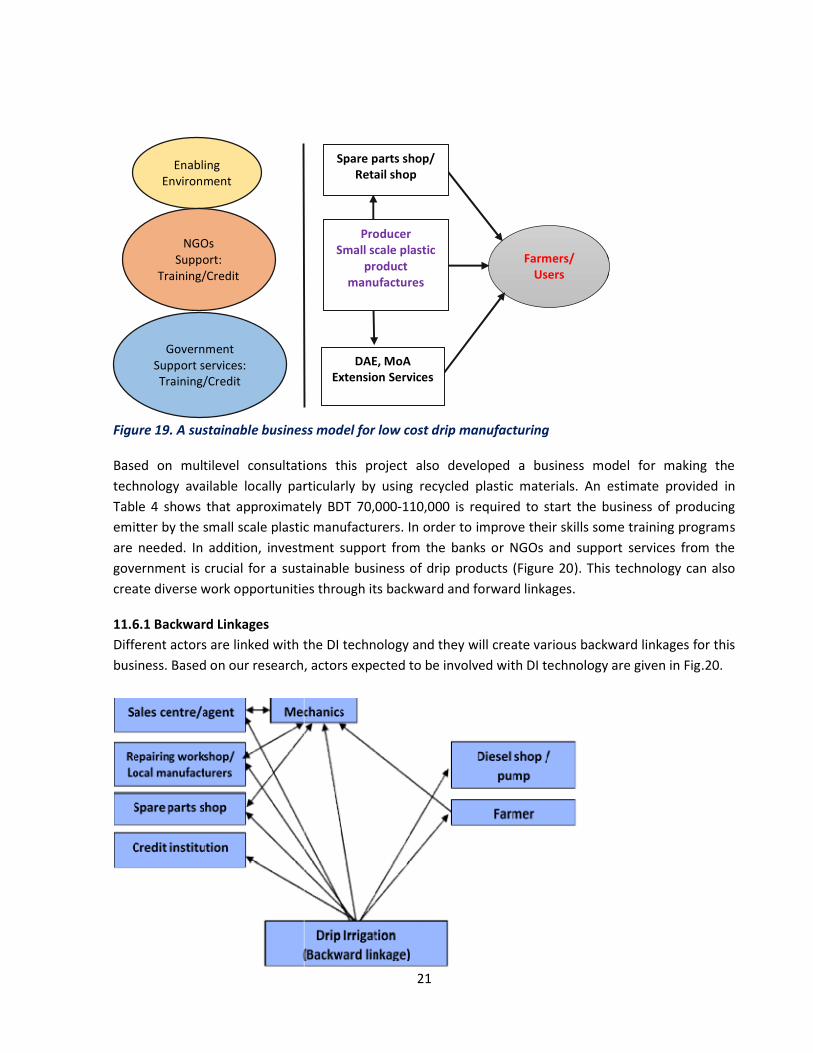
Figure 19. A sustainable business model for low cost drip manufacturing
Based on multilevel consultations this project also developed a business model for making the technology available locally particularly by usingTable 4 shows that approximately emitter by the small scale plastic manufacturers. In order to improve their skills some training programare needed. In addition, investment support from the banks or NGOs and support services from the government is crucial for a sustainable business of drip products (Figure 20create diverse work opportunities through its backwar
11.6.1 Backward Linkages Different actors are linked with thebusiness. Based on our research, ac
Enabling Environment
Government Support services: Training/Credit
NGOs Support:
Training/Credit
21
. A sustainable business model for low cost drip manufacturing
Based on multilevel consultations this project also developed a business model for making the technology available locally particularly by using recycled plastic materials. An estimate
shows that approximately BDT 70,000-110,000 is required to start the business of producing emitter by the small scale plastic manufacturers. In order to improve their skills some training programare needed. In addition, investment support from the banks or NGOs and support services from the government is crucial for a sustainable business of drip products (Figure 20). This technology can also create diverse work opportunities through its backward and forward linkages.
the DI technology and they will create various backward linkages for this Based on our research, actors expected to be involved with DI technology are given in Fig
Farmers/ Users
Spare parts shop/ Retail shop
Producer Small scale plastic
product manufactures
DAE, MoA Extension Services
Based on multilevel consultations this project also developed a business model for making the estimate provided in
is required to start the business of producing emitter by the small scale plastic manufacturers. In order to improve their skills some training programs are needed. In addition, investment support from the banks or NGOs and support services from the
This technology can also
ate various backward linkages for this tors expected to be involved with DI technology are given in Fig.20.

22
Figure 20. Actors Involved with DI Technology 11.6.2 Forward Linkages Numerous studies have revealed that DI technology have significant positive contribution to increasing production, particularly for Robi crops. This technology has contribution to increase water use efficiency which in turn facilitates increased yield, greater cropping intensity and the possibility of introduction of new crop rotations. When production increases, more agro-based activities are also developed. As a result more opportunities for productive work are created. These small scale agro-based industries as a result of large-scale use of DI and other technology create forward linkages. It offers great scope for capital investment by the individual entrepreneurs, which will open up new employment avenues for the ever growing rural people. For the development of these growing agro-based industries continuous supply of raw materials such as capital and training should be ensured.
12. Research highlight/findings
Computation fluid dynamics modelling was introduced for the first time in Bangladesh for the design of an micro emitter
The velocity vector profiles and the hydraulic characteristics of the emitter was documented. The newly developed emitter is able to work under very low pressure (10-20 kPa); The average discharge of the emitter is 3.3 L/h in the field condition; Distribution uniformity of the emitter was between 83 to 90%; Flow variation of the newly developed emitter is limited to 12% at best Average production cost of emitter is around BDT 5 Producers have been trained to bring competition in the market
B. Implementation Position 1. Procurement:
Description of equipment and capital items
PP Target Achievement Remarks
Phy (#) Fin (Tk) Phy (#) Fin (Tk)
(a) Office equipment NA NA NA NA NA
(b) Lab &field equipment
UV Spectrophotometer
Portable PH Meter
Dissolved Oxygen Meter
Orbital Shaker
Notebook
1
1
1
1
1
0
2,60,000.00
30,000.00
25,000.00
30,000.00
58,000.00
1
1
1
1
1
2,60,000.00
30,000.00
25,000.00
30,000.00
58,000.00
(c) Other capital items Emitters Project Completion report
5000 100
0 2,00,000.00 89,000.00
5000 100
2,00,000.00 89,000.00
Total - 6,92,000.00 - 6,92,000.00 -

23
2. Establishment/renovation facilities:
Description of facilities Newly established Upgraded/refurbished Remarks
PP Target Achievement PP Target Achievement
Construction of a Test rig 1 1 1 1
Laboratory facility 1 1
3. Training/study tour/ seminar/workshop/conference organized:
Description Number of participant Duration (Days/weeks/
months) Remarks
Male Female Total
(a) Training 40 10 50 1
(b) Workshop
C. Financial and physical progress
Figures in BDT Items of expenditure/activities Total
approved
budget
Fund
received
Actual
expenditure
Balance/
unspent
Physical
progress
(%)
Reasons
for
deviation
A. Contractual staff salary 352051 474751 352051 0 100%
B. Field research/lab expenses and
supplies
1140970 778588 1140000 970 100%
C. Operating expenses 189794 145725 144345 45449 76% Sufficed
D. Vehicle hire and fuel, oil &
maintenance
200000 225500 198910 1090 100%
E. Training/workshop/seminar etc. 70000 70000 70000 0 100%
F. Publications and printing 104000 0 15000 89000 14% PCR to be
printed by BARC
G. Miscellaneous 40000 24712 30000 10000 75% Sufficed
H. Capital expenses 403000 653500 403000 0 100%
Total 2499815 2372776 2353306 146509 - -

24
D. Achievement of Sub-project by objectives: (Tangible form) Specific objectives of the sub-project
Major technical activities performed in respect of the set
objectives
Output(i.e. product obtained, visible,
measurable)
Outcome(short term effect of the research)
1. Design a labyrinth type pressure compensated drip emitter for micro irrigation;
Numerical simulation
Computation fluid dynamic modeling
Use of a diaphragm to compensate pressure
Use of labyrinths to compensate pressure
Nine-toothed labyrinth designed
Velocity vector profile of the emitters
Stable flow vs discharge relationship
A suitable elastic membrane identified
• The first ever PC emitter has been designed and manufactured in Bangladesh
• Small scale plastic manufacturers can access the design free of cost to manufacture their own set of drippers.
2. Manufacture emitters and improve their water application uniformity indices, and
In-field performance evaluation of micro emitters according to ASABE protocols
Laboratory hydraulic testing of the emitters
Different heads i.e., 10, 15 and 20 kPa pressure applied to measure the performance
The first emitter designed in Bangladesh was manufactured
The average discharge of the emitter is 3.3 L/h in the field condition;
Distribution uniformity of the emitter is between 83 to 90%;
Flow variation of the newly developed emitter is limited to 12% at best
• Due to more manufacturer entering the market, dripper price is expected to come down.
• Farmers would now have to invest less for a drip irrigation set since the newly developed emitter cost one third of the imported emitters.
• Researchers can also contribute towards improving the uniformity of the emitter.
3. Identify the backward and forward linkages for a sustainable business of drip products.
• Market analysis regarding the retail cost of emitters
Inventory studies in the selected business outlets
A sustainable business model has been established.
Investments and the annual average cost of investment for drip manufacturing has been calculated
• Existing small scale plastic manufacturers now have the financial information they need for a new window of drip business.
• New startups can also take this report as a baseline material for their business.

25
E. Materials Development/Publication made under the Sub-project:
Publication
Number of publication Remarks (e.g. paper title, name of journal, conference name, etc.) Under
preparation Completed
and published
Technology bulletin/leaflet/flyer etc.
- - -
Journal publication 02 - Two articles being prepared for: 1. Agricultural Water Management -
Elsevier (IF: 3.56) 2. Computer and Electronics in
Agriculture - Elsevier (IF 2.76)
MS Theses - 02 1. Design and development of a compensated emitter for micro irrigation – a thesis towards MS in Irrigation and Water Management (Completed) at BSMRAU
2. Numerical simulation in the design of a pressure compensated emitter - a thesis towards MS in Mechanical Engineering at BUET (Ongoing)
F. Technology/Knowledge generation/Policy Support (as applied):
i. Generation of technology (Commodity & Non-commodity)
ii. Generation of new knowledge that help in developing more technology in future
iii. Technology transferred that help increased agricultural productivity and farmers’ income
iv. Policy Support
A labyrinth type drip emitter has been designed and developed
Low velocity regions in a labyrinth type emitter has been identified for future research
Low-cost drip technology saving irrigation water and increasing command area of pumps
Elements that require policy support for a sustainable drip business has been identified

G. Information regarding Desk and Field Monitoring
i) Desk Monitoring:
Monitoring workshop organized by management of the project and for its successful completion.
ii) Field Monitoring: a. Internal monitoring of Bangabandhu Sheikh Mujibur Rahman Agricultural University, Gazipur 1706
has been done at difannual research review workshop of BSMRAU.
b. The following personnel had been contacted and sought advices from, at different stages of this product development. They have also bee
Professor Dr. Moshiul Islam, Department of Agronomy, Bangabandhu Sheikh Mujibur Rahman Agricultural University, Gazipur 1706
Dr. Md. Arif. HasanMamun, Professor, Dept. of Mechanical Engineering, BanglUniversity of Engineering and Technology, Dhaka 1000. Tel: +8801819487324
Dr. Sumon Saha, Associate Professor, Dept. of Mechanical Engineering, Bangladesh University of Engineering and Technology, Dhaka 1000. Tel: +8801926197002
Nusrat Jahan,
Sonkolon Barua, Computational Fluid Dynamics (CFD) Modelling Expert, M.Sc. (Mechanical Engineering), BUET, Dhaka 1000. Tel: +8801715377640
I. Lesson Learned/Challenges (if any)
CFD modelling provides hydrodynamic information in detail 3D printing technology does not work in producing micro emitters Automatic injection molding provides better results in terms of precision manufacturing
J. Challenges (if any)
Maintaining the same level of precision Automatic injection molding may help in this regard.
Clogging from suspended particles from water is another challenge that farmers may have to overcome by flushing the system at
Dr. Md. Moinul Hosain Oliver Principal Investigator Associate Professor, Bangabandhu Sheikh Mujibur Rahman Agricultural UniversityGazipur 1706, Bangladesh Email: [email protected] Date: 03 February 2019
26
ding Desk and Field Monitoring
Monitoring workshop organized by BARC provided valuable guidelines and suggestions about management of the project and for its successful completion. 18 – 25 September 2018.
Internal monitoring of Bangabandhu Sheikh Mujibur Rahman Agricultural University, Gazipur 1706 has been done at different times. There has been a presentation of the project activities in the annual research review workshop of BSMRAU.
personnel had been contacted and sought advices from, at different stages of this product development. They have also been involved in monitoring the progress of the project.
Professor Dr. Moshiul Islam, Department of Agronomy, Bangabandhu Sheikh Mujibur Rahman Agricultural University, Gazipur 1706
Dr. Md. Arif. HasanMamun, Professor, Dept. of Mechanical Engineering, BanglUniversity of Engineering and Technology, Dhaka 1000. Tel: +8801819487324
Dr. Sumon Saha, Associate Professor, Dept. of Mechanical Engineering, Bangladesh University of Engineering and Technology, Dhaka 1000. Tel: +8801926197002
Nusrat Jahan, Scientific Officer, BARI, Gazipur 1700
Sonkolon Barua, Computational Fluid Dynamics (CFD) Modelling Expert, M.Sc. (Mechanical Engineering), BUET, Dhaka 1000. Tel: +8801715377640
/Challenges (if any)
CFD modelling provides hydrodynamic information in detail 3D printing technology does not work in producing micro emitters Automatic injection molding provides better results in terms of precision manufacturing
level of precision while producing each batch drippersAutomatic injection molding may help in this regard. Clogging from suspended particles from water is another challenge that farmers may have to overcome by flushing the system at regular intervals.
Bangabandhu Sheikh Mujibur Rahman Agricultural University,
Dr. A. K. M. Aminul IslamDirector (Research) Bangabandhu Sheikh Mujibur Rahman Agricultural University, Gazipur 1706Tel: +88029205324 Email: [email protected] : 03 February 2019
guidelines and suggestions about 25 September 2018.
Internal monitoring of Bangabandhu Sheikh Mujibur Rahman Agricultural University, Gazipur 1706 ferent times. There has been a presentation of the project activities in the
personnel had been contacted and sought advices from, at different stages of this n involved in monitoring the progress of the project.
Professor Dr. Moshiul Islam, Department of Agronomy, Bangabandhu Sheikh Mujibur
Dr. Md. Arif. HasanMamun, Professor, Dept. of Mechanical Engineering, Bangladesh University of Engineering and Technology, Dhaka 1000. Tel: +8801819487324
Dr. Sumon Saha, Associate Professor, Dept. of Mechanical Engineering, Bangladesh University of Engineering and Technology, Dhaka 1000. Tel: +8801926197002
Sonkolon Barua, Computational Fluid Dynamics (CFD) Modelling Expert, M.Sc. (Mechanical
Automatic injection molding provides better results in terms of precision manufacturing
drippers is a challenge.
Clogging from suspended particles from water is another challenge that farmers may have to
Dr. A. K. M. Aminul Islam
Bangabandhu Sheikh Mujibur Rahman Agricultural University, Gazipur 1706
[email protected] : 03 February 2019

27
References
[1] Adin, A., Sacks, M., 1991. Dripper-clogging factors in wastewater irrigation. Journal of Irrigation and Drainage Engineering 117, 813-826.
[2] Amin, M.S.M., Svehlik, Z.J., 1994. Hydraulic analysis of micro-irrigation laterals: A new approach. Pertanika Journal of Science & Technology 2, 107-119.
[3] ASABE, 2003. ASAE Engineering Practice EP 405.1: Design and Installation of Microirrigation Systems. American Society of Agricultural and Biological Engineers, St. Joseph, Michigan, pp. 901–905.
[4] Boswell, M., 1990. Micro-irrigation design manual, 4 ed. James Hardie Irrigation, El Cajon, California, p. 178.
[5] Capra, A., Scicolone, B., 2004. Emitter and filter tests for wastewater reuse by drip irrigation. Agricultural Water Management 68, 135-149.
[6] deKreij, C., Burg van der, A.M.M., Runia, W.T., 2003. Drip irrigation emitter clogging in Dutch greenhouses as affected by methane and organic acids. Agricultural Water Management 60, 73-85.
[7] Goldberg, S.D., 1971. World survey confirms growth of trickle irrigation, in: Larkman, B. (Ed.), Trickle Irrigation. Imperial Chemical Industires Ltd., Melbourne, p. 8.
[8] Howell, T.A., 2000. Irrigation's role in enhancing water use efficiency, in: Evans, R.G. (Ed.), Fourth Decennial National Irrigation Symposium. American Society of Agricultural and Biological Engineers, Phoenix Arizona, pp. 66-80.
[9] Kirnak, H., Dogan, E., Demir, S., Yalcin, S., 2004. Determination of hydraulic performance of trickle irrigation emitters used in irrigation systems in the Harran Plain. Turkish Journal of Agriculture and Forestry 28, 223-230.
[10] Lamm, F., Bordovsky, J., Schwankl, L., Grabow, G., Enciso-Medina, J., Peters, R., Colaizzi, P., Trooien, T., Porter, D., 2012. Subsurface drip irrigation: Status of the technology in 2010. Transactions of the ASABE 55, 483-491.
[11] Lazarova, V., Bahri, A.a., Bahri, A., 2005. Water reuse for irrigation : agriculture, landscapes, and turf grass. CRC Press, Boca Raton, Fla.
[12] Li, Y., Liu, H., Yang, P., Wu, D., 2013. Analysis of tracing ability of different sized particles in drip irrigation emitters with computational fluid dynamics. Irrigation and Drainage 62, 340-351.
[13] Liu, S.H., Li, Y.K., Liu, Y.Z., Yang, P.L., Ren, S.M., Wei, R.J., Xu, H.B., 2009. Flow characteristics in energy dissipation units of labyrinth path in the drip irrigation emitters with DPIV technology. Journal of Hydrodynamics 21, 137-145.
[14] Oliver, M. M. H., Hewa, G. A., & Pezzaniti, D., 2016. Thermal variation and pressure compensated emitters. Agricultural Water Management, 176, 29-39. http://dx.doi.org/10.1016/j.agwat.2016.05.012
[15] Oliver, M.M.H., Talukder, M.S.U., Ahmed, M., 2008. Alternate wetting and drying irrigation for rice cultivation. Journal of the Bangladesh Agricultural University 6, 409-414.
[16] Qingsong, W., Gang, L., Jie, L., Yusheng, S., Wenchu, D., Shuhuai, H., 2008. Evaluations of emitter clogging in drip irrigation by two-phase flow simulations and laboratory experiments. Computers and Electronics in Agriculture 63, 294-303.
[17] Schwankl, L.J., Hanson, B.R., 2007. Surface Drip Irrigation, in: Lamm, F.R., Ayars, J.E., Nakayama, F.S. (Eds.), Microirrigation for Crop Production. Design, Operation and Management. Elsevier, Amsterdam, pp. 431- 472.
[18] Zhang, J., Zhao, W., Tang, Y., Lu, B., 2010. Anti-clogging performance evaluation and parameterized design of emitters with labyrinth channels. Computers and Electronics in Agriculture 74, 59-65.