Displacement ductility for seismic design of RC walls for low-rise housing
Upload
khangminh22Category
view
4download
0
International Journal of Interdisciplinary Innovative Research & Development (IJIIRD)
ISSN: 2456-236X
Vol. 02 Issue 02 | 2018
020220 www.ijiird.com 140
STUDY ON SEISMIC BEHAVIOR OF RC
STRUCTURE WITH AND WITHOUT
SHEAR WALL
Prof. A.S.Gawande
1 ,Mr H.N.Gadge
2
1Guide Department of Civil Engineering, College of Engineering and Technology Akola
2M.E (Structural Engg),Department of civil Engineering, C.O.E.T. Akola, Maharashtra, India
ABSTRACT From the past records of earthquake, there's increase in the demand of earthquake resisting
building which might be fulfilled by providing the shear wall systems in the buildings. For achieving
economy in reinforced concrete building structures, design of crucial section is carefully done to induce
reasonable concrete sizes and optimum steel consumption in members. in the present study, a trial has been
made to model 04 story building with and without shear walls by static analysis method for earthquake zone
III. Software is employed for the analysis. The target of this study is to assess the comparative seismic
performance of buildings in terms of displacement, story drift, base shear and cost and carpet area. Buildings
with shear wall area unit economical as compared to without shear wall.
1. INTRODUCTION 1.1 General
Shear walls are vertical elements of the horizontal force resisting system. Shear walls are constructed to counter
the effects of lateral load acting on a structure. In residential construction, shear walls are straight external walls
that typically form a box which provides all of the lateral support for the building .When shear walls are
designed and constructed properly, and they will have the strength and stiffness to resist the horizontal forces.
Shear Walls are structural elements in addition to slabs, beams and columns. These walls generally start at
foundation level and are continuous throughout the building height. Their thickness can be low as 150mm, or as
high as 400mm in high rise buildings. Shear walls are usually provided both length and width of buildings.
Shear walls are like vertically – oriented wide beams that carry earthquake loads downwards to the foundation.
Properly designed and detailed building with shear walls has shown very good performance in past earthquakes.
Shear wall in high seismic regions require special detailing. Shear wall buildings are commonly used for
residential purposes.
1.2 Need- Shear walls are not only designed to resist gravity / vertical loads (due to its1self-weight and other
living / moving loads), but they are also designed for Lateral loads of earthquakes / wind. The walls are
structurally integrated with roofs / floors (diaphragms) and other Lateral walls running across at right angles,
thereby giving the three Dimensional stability for the building structures. Shear wall structural systems are more
stable. Other lateral wall running across at right angle, thereby giving the three dimensional stability for the
building structures.
1.3 Objective-
1. To study seismic effect of RC building.
2. To study methods of Seismic Analysis.
3. To study Analysis of Design process of share wall.
4. To study steel shear wall.
5. To study RCC shear wall.
6. To do comparative Study of steel and RCC shear wall.
International Journal of Interdisciplinary Innovative Research & Development (IJIIRD)
ISSN: 2456-236X
Vol. 02 Issue 02 | 2018
020220 www.ijiird.com 141
2. DETAIL STUDY 2.1 What is a Shear Wall Building?
Shear walls are vertical elements of the horizontal force resisting system. Shear walls are constructed
to counter the effects of lateral load acting on a structure. In residential construction, shear walls are straight
external walls that typically form a box which provides all of the lateral support for the building
2.2 PURPOSE OF CONSTRUCTING SHEAR WALLS
Shear walls are not only designed to resist gravity / vertical loads (due to its self-weight and other living /
moving loads), but they are also designed for lateral loads of earthquakes / wind. The walls are structurally
integrated with roofs / floors (diaphragms) and other lateral walls running across at right angles, thereby giving
the three dimensional stability for the building structures.Shear wall structural systems are more stable. Because,
their supporting area (total cross-sectional area of all shear walls) with reference to total plans area of building,
is comparatively more, unlike in the case of RCC framed structures.
Walls have to resist the uplift forces caused by the pull of the wind. Walls have to resist the shear forces
that try to push the walls over. Walls have to resist the lateral force of the wind that tries to push the walls in and
pull them away from the building.
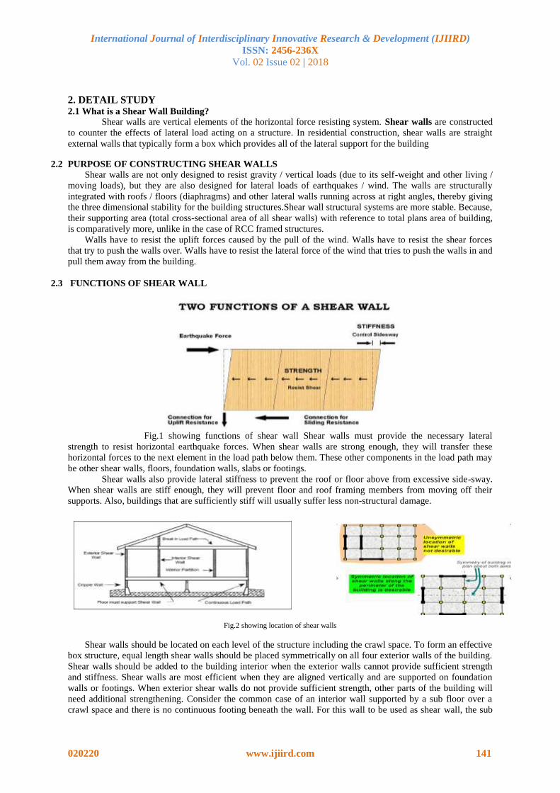
2.3 FUNCTIONS OF SHEAR WALL
Fig.1 showing functions of shear wall Shear walls must provide the necessary lateral
strength to resist horizontal earthquake forces. When shear walls are strong enough, they will transfer these
horizontal forces to the next element in the load path below them. These other components in the load path may
be other shear walls, floors, foundation walls, slabs or footings.
Shear walls also provide lateral stiffness to prevent the roof or floor above from excessive side-sway.
When shear walls are stiff enough, they will prevent floor and roof framing members from moving off their
supports. Also, buildings that are sufficiently stiff will usually suffer less non-structural damage.
Fig.2 showing location of shear walls
Shear walls should be located on each level of the structure including the crawl space. To form an effective
box structure, equal length shear walls should be placed symmetrically on all four exterior walls of the building.
Shear walls should be added to the building interior when the exterior walls cannot provide sufficient strength
and stiffness. Shear walls are most efficient when they are aligned vertically and are supported on foundation
walls or footings. When exterior shear walls do not provide sufficient strength, other parts of the building will
need additional strengthening. Consider the common case of an interior wall supported by a sub floor over a
crawl space and there is no continuous footing beneath the wall. For this wall to be used as shear wall, the sub
International Journal of Interdisciplinary Innovative Research & Development (IJIIRD)
ISSN: 2456-236X
Vol. 02 Issue 02 | 2018
020220 www.ijiird.com 142
floor and its connections will have to be strengthened near the wall. For Retrofit work, existing floor
construction is not easily changed. That’s the reason why most retrofit work uses walls with continuous footings
underneath them as shear walls.
2.4 METHODS OF DESIGN OF SHEAR WALL There are three types of design methods
Segmented shear wall method
Force transfer –ground openings method
Perforated shear wall method
2.4.1 Segmented shear wall method
The segmented shear wall method uses full height shear wall segments that comply with ratio
requirements and are usually restrained against overturning by hold down devices at the ends of each segment.
2.4.2 Force transfer –ground openings method
The second method force transfer-ground openings method consider the entire shear wall with openings and the
wall piers adjacent to openings are segments. The method requires the forces around the perimeter of the
openings to be analyzed, designed, and detailed. With this method, the hold-down devices generally occur at the
ends of the shear wall, not at each wall pier, and special reinforcement around the opening is often required.
The perforated shear wall method, however, specifically requires hold-down devices at each end of the
perforated shear wall.
2.5 TYPES OF SHEAR WALLS
RC Shear Wall
Plywood Shear Wall
Midply Shear Wall
RC Hollow Concrete Block Masonry Wall
Steel Plate Shear Wall
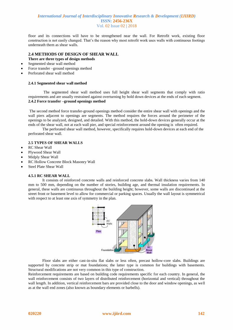
4.5.1 RC SHEAR WALL
It consists of reinforced concrete walls and reinforced concrete slabs. Wall thickness varies from 140
mm to 500 mm, depending on the number of stories, building age, and thermal insulation requirements. In
general, these walls are continuous throughout the building height; however, some walls are discontinued at the
street front or basement level to allow for commercial or parking spaces. Usually the wall layout is symmetrical
with respect to at least one axis of symmetry in the plan.
Floor slabs are either cast-in-situ flat slabs or less often, precast hollow-core slabs. Buildings are
supported by concrete strip or mat foundations; the latter type is common for buildings with basements.
Structural modifications are not very common in this type of construction.
Reinforcement requirements are based on building code requirements specific for each country. In general, the
wall reinforcement consists of two layers of distributed reinforcement (horizontal and vertical) throughout the
wall length. In addition, vertical reinforcement bars are provided close to the door and window openings, as well
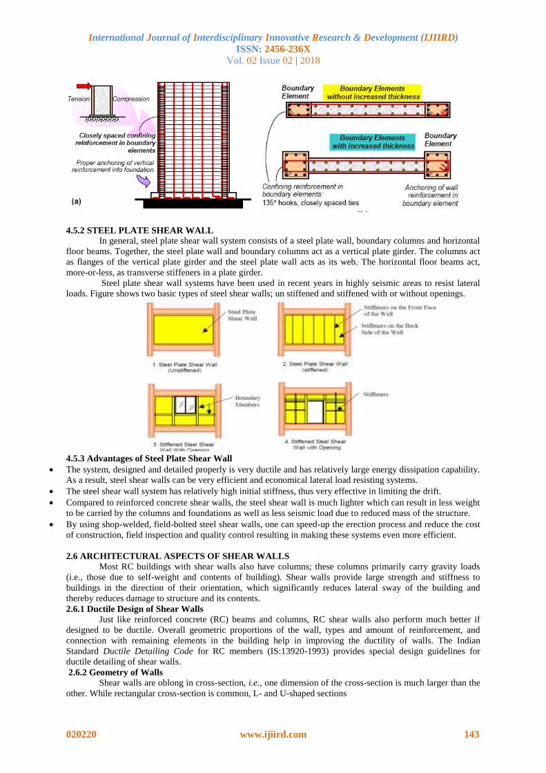
as at the wall end zones (also known as boundary elements or barbells).
International Journal of Interdisciplinary Innovative Research & Development (IJIIRD)
ISSN: 2456-236X
Vol. 02 Issue 02 | 2018
020220 www.ijiird.com 143
4.5.2 STEEL PLATE SHEAR WALL
In general, steel plate shear wall system consists of a steel plate wall, boundary columns and horizontal
floor beams. Together, the steel plate wall and boundary columns act as a vertical plate girder. The columns act
as flanges of the vertical plate girder and the steel plate wall acts as its web. The horizontal floor beams act,
more-or-less, as transverse stiffeners in a plate girder.
Steel plate shear wall systems have been used in recent years in highly seismic areas to resist lateral
loads. Figure shows two basic types of steel shear walls; un stiffened and stiffened with or without openings.
4.5.3 Advantages of Steel Plate Shear Wall
The system, designed and detailed properly is very ductile and has relatively large energy dissipation capability.
As a result, steel shear walls can be very efficient and economical lateral load resisting systems.
The steel shear wall system has relatively high initial stiffness, thus very effective in limiting the drift.
Compared to reinforced concrete shear walls, the steel shear wall is much lighter which can result in less weight
to be carried by the columns and foundations as well as less seismic load due to reduced mass of the structure.
By using shop-welded, field-bolted steel shear walls, one can speed-up the erection process and reduce the cost
of construction, field inspection and quality control resulting in making these systems even more efficient.
2.6 ARCHITECTURAL ASPECTS OF SHEAR WALLS
Most RC buildings with shear walls also have columns; these columns primarily carry gravity loads
(i.e., those due to self-weight and contents of building). Shear walls provide large strength and stiffness to
buildings in the direction of their orientation, which significantly reduces lateral sway of the building and
thereby reduces damage to structure and its contents.
2.6.1 Ductile Design of Shear Walls
Just like reinforced concrete (RC) beams and columns, RC shear walls also perform much better if
designed to be ductile. Overall geometric proportions of the wall, types and amount of reinforcement, and
connection with remaining elements in the building help in improving the ductility of walls. The Indian
Standard Ductile Detailing Code for RC members (IS:13920-1993) provides special design guidelines for
ductile detailing of shear walls.
2.6.2 Geometry of Walls
Shear walls are oblong in cross-section, i.e., one dimension of the cross-section is much larger than the
other. While rectangular cross-section is common, L- and U-shaped sections

International Journal of Interdisciplinary Innovative Research & Development (IJIIRD)
ISSN: 2456-236X
Vol. 02 Issue 02 | 2018
020220 www.ijiird.com 144
2.6.3 Reinforcement Bars in RC Walls
Steel reinforcing bars are to be provided in walls in regularly spaced vertical and horizontal grids. The
vertical and horizontal reinforcement in the wall can be placed in one or two parallel layers called curtains.
Horizontal reinforcement needs to be anchored at the ends of walls. The minimum area of reinforcing steel to be
provided is 0.0025 times the cross-sectional area, along each of the horizontal andvertical directions. This
vertical reinforcement should be distributed uniformly across the wall cross-section.
2.7 Determination of base shear:
For the determination of seismic forces, the country is classified in four seismic zones as shown in fig.
4.2. The total design lateral force or design base shear along any principal direction shall be determined by this
expression:
Vb =Ah W ----------(2.6)
Where, Ah = design horizontal seismic coefficient for a structure
W= seismic weight of building
The design horizontal seismic coefficient for a structure Ah is given by:
Ah = (ZISa)/ (2Rg) --------(2.7)
Z is the zone factor given in Table 4.1 of IS 1893:2002 (part 1) for the maximumconsidered earthquake (MCE)
and service life of a structure in a zone. The factor 2 isto reduce the MCE to the factor for design base
earthquake (DBE). Table 2.1: Zone factor, Z
Seismic zone II III IV V
Seismic intensity Low Moderate Severe Very severe
Z 0.10 0.16 0.24 0.36
Fig. 2.3 Seismic zones of India
I is the importance factor, depending upon the functional use of the structure, characterized by hazardous
consequences of its failure, post-earthquake functional needs, historical or economic importance. The minimum
values of importance factor are given in table 4.2 of IS 1893:2002. Table 2.2: Importance factor, I
Structure I
Important service and community building, such as hospitals; schools; monumental structures;
emergency buildings like telephone exchanges television stations, radio stations, fire station
buildings; large community halls like cinemas, assembly halls; and subway stations, power stations.
1.5
All other buildings 1
R is the response reduction factor, depending on the perceived seismic damage performance of the structure,
characterized by ductile or brittle deformations. The need for introducing R in base shear formula is an attempt
to consider the structure’s inelastic characteristics in linear analysis. as it is undesirable as well as uneconomical
International Journal of Interdisciplinary Innovative Research & Development (IJIIRD)
ISSN: 2456-236X
Vol. 02 Issue 02 | 2018
020220 www.ijiird.com 145
to design a structure on the basis that it will remain in elastic range for all major earthquakes. Note: IS code
recommends that the value of I/R should not exceed 1.0 the values of R are given in Table 4.3 of IS 1893:2002
(part 1).
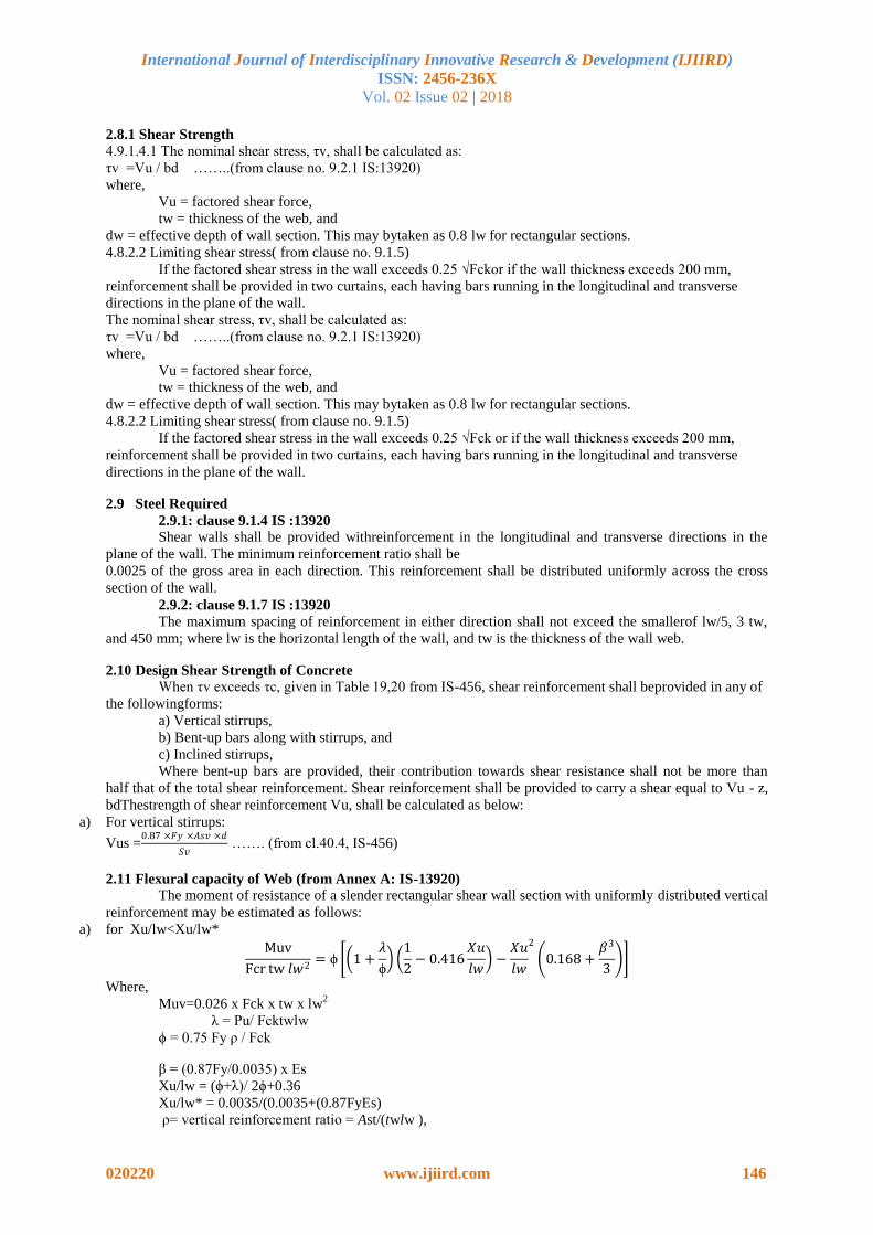
Table 2.3: Response reduction factor for building systems, R
Lateral load-resisting system R
Building frame systems
Ordinary RCC moment-resisting frame (OMRF)
Special RCC moment-resisting frame (SMRF)
3
5
Steel frame with
a) Concentric braces
b) Eccentric braces
Steel moment-resisting frame designed as per SP 6 (6)
4.0
5.0
5.0
Building with shear walls
Load bearing masonry wall building
a) Unreinforced
b) Reinforced with horizontal RCC bands
c) Reinforced with horizontal RCC bands and vertical bars at corner of rooms and jambs of
openings
1.5
2.5
3.0
Ordinary RCC shear walls 3.0
Ductile shear walls 4.0
Building with dual systems
Ordinary shear wall with OMRF
Ordinary shear wall with SMRF
Ductile shear wall with OMRF
Ductile shear wall with SMRF
3.0
4.0
4.5
5.0
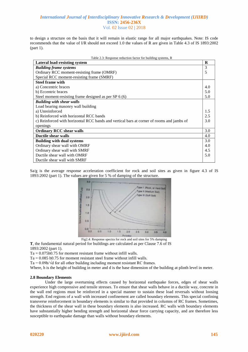
Sa/g is the average response acceleration coefficient for rock and soil sites as given in figure 4.3 of IS
1893:2002 (part 1). The values are given for 5 % of damping of the structure.
Fig2.4: Response spectra for rock and soil sites for 5% damping
T, the fundamental natural period for buildings are calculated as per Clause 7.6 of IS
1893:2002 (part 1).
Ta = 0.075h0.75 for moment resistant frame without infill walls.
Ta = 0.085 h0.75 for moment resistant steel frame without infill walls.
Ta = 0.09h/√d for all other building including moment resistant RC frames.
Where, h is the height of building in meter and d is the base dimension of the building at plinth level in meter.
2.8 Boundary Elements Under the large overturning effects caused by horizontal earthquake forces, edges of shear walls
experience high compressive and tensile stresses. To ensure that shear walls behave in a ductile way, concrete in
the wall end regions must be reinforced in a special manner to sustain these load reversals without loosing
strength. End regions of a wall with increased confinement are called boundary elements. This special confining
transverse reinforcement in boundary elements is similar to that provided in columns of RC frames. Sometimes,
the thickness of the shear wall in these boundary elements is also increased. RC walls with boundary elements
have substantially higher bending strength and horizontal shear force carrying capacity, and are therefore less
susceptible to earthquake damage than walls without boundary elements.
International Journal of Interdisciplinary Innovative Research & Development (IJIIRD)
ISSN: 2456-236X
Vol. 02 Issue 02 | 2018
020220 www.ijiird.com 146
2.8.1 Shear Strength
4.9.1.4.1 The nominal shear stress, τv, shall be calculated as:
τv =Vu / bd ……..(from clause no. 9.2.1 IS:13920)
where,
Vu = factored shear force,
tw = thickness of the web, and
dw = effective depth of wall section. This may bytaken as 0.8 lw for rectangular sections.
4.8.2.2 Limiting shear stress( from clause no. 9.1.5)
If the factored shear stress in the wall exceeds 0.25 √Fckor if the wall thickness exceeds 200 mm,
reinforcement shall be provided in two curtains, each having bars running in the longitudinal and transverse
directions in the plane of the wall.
The nominal shear stress, τv, shall be calculated as:
τv =Vu / bd ……..(from clause no. 9.2.1 IS:13920)
where,
Vu = factored shear force,
tw = thickness of the web, and
dw = effective depth of wall section. This may bytaken as 0.8 lw for rectangular sections.
4.8.2.2 Limiting shear stress( from clause no. 9.1.5)
If the factored shear stress in the wall exceeds 0.25 √Fck or if the wall thickness exceeds 200 mm,
reinforcement shall be provided in two curtains, each having bars running in the longitudinal and transverse
directions in the plane of the wall.
2.9 Steel Required
2.9.1: clause 9.1.4 IS :13920
Shear walls shall be provided withreinforcement in the longitudinal and transverse directions in the
plane of the wall. The minimum reinforcement ratio shall be
0.0025 of the gross area in each direction. This reinforcement shall be distributed uniformly across the cross
section of the wall.
2.9.2: clause 9.1.7 IS :13920
The maximum spacing of reinforcement in either direction shall not exceed the smallerof lw/5, 3 tw,
and 450 mm; where lw is the horizontal length of the wall, and tw is the thickness of the wall web.
2.10 Design Shear Strength of Concrete
When τv exceeds τc, given in Table 19,20 from IS-456, shear reinforcement shall beprovided in any of
the followingforms:
a) Vertical stirrups,
b) Bent-up bars along with stirrups, and
c) Inclined stirrups,
Where bent-up bars are provided, their contribution towards shear resistance shall not be more than
half that of the total shear reinforcement. Shear reinforcement shall be provided to carry a shear equal to Vu - z,
bdThestrength of shear reinforcement Vu, shall be calculated as below:
a) For vertical stirrups:
Vus =0.87 ×𝐹𝑦 ×𝐴𝑠𝑣 ×𝑑
𝑆𝑣 ……. (from cl.40.4, IS-456)
2.11 Flexural capacity of Web (from Annex A: IS-13920)
The moment of resistance of a slender rectangular shear wall section with uniformly distributed vertical
reinforcement may be estimated as follows:
a) for Xu/lw<Xu/lw*
Muv
Fcr tw 𝑙𝑤2= ϕ 1 +
𝜆
ϕ
1
2− 0.416
𝑋𝑢
𝑙𝑤 −
𝑋𝑢
𝑙𝑤
2
0.168 +𝛽3
3
Where,
Muv=0.026 x Fck x tw x lw2
λ = Pu/ Fcktwlw
ϕ = 0.75 Fy ρ / Fck
β = (0.87Fy/0.0035) x Es
Xu/lw = (ϕ+λ)/ 2ϕ+0.36
Xu/lw* = 0.0035/(0.0035+(0.87FyEs)
ρ= vertical reinforcement ratio = Ast/(twlw ),
International Journal of Interdisciplinary Innovative Research & Development (IJIIRD)
ISSN: 2456-236X
Vol. 02 Issue 02 | 2018
020220 www.ijiird.com 147
Ast = area of uniformly distributed vertical reinforcement,
β = 0.87 fy/(0.003 5 Es),
Es = elastic modulus of steel, and
Pu = axial compression on wall.
2.12 Force on Boundary Elements
Load on Web Pw = Load x Web Area/ Total area
Load on Boundary Element = Load x BE /Total area
2.13 Design of Boundary Element
Pu=0.4 Fck Ac + 0.67 FyAsc ………. (from cl.39.3,IS-456)
The area of cross section, Ash, of the bar forming rectangular hoop, to be used as special confining
reinforcement shall not be less than
Ash= 0.18 Sh (Fck/Fy) ((Ag/Ak)-1)…... (from cl.7.4.8, IS-13920:1993)
Where, h = longer dimension of the rectangular confining hoop measured to its outerface.Ak = area of
confined concrete core in the rectangular hoop measured to its outside dimensions.
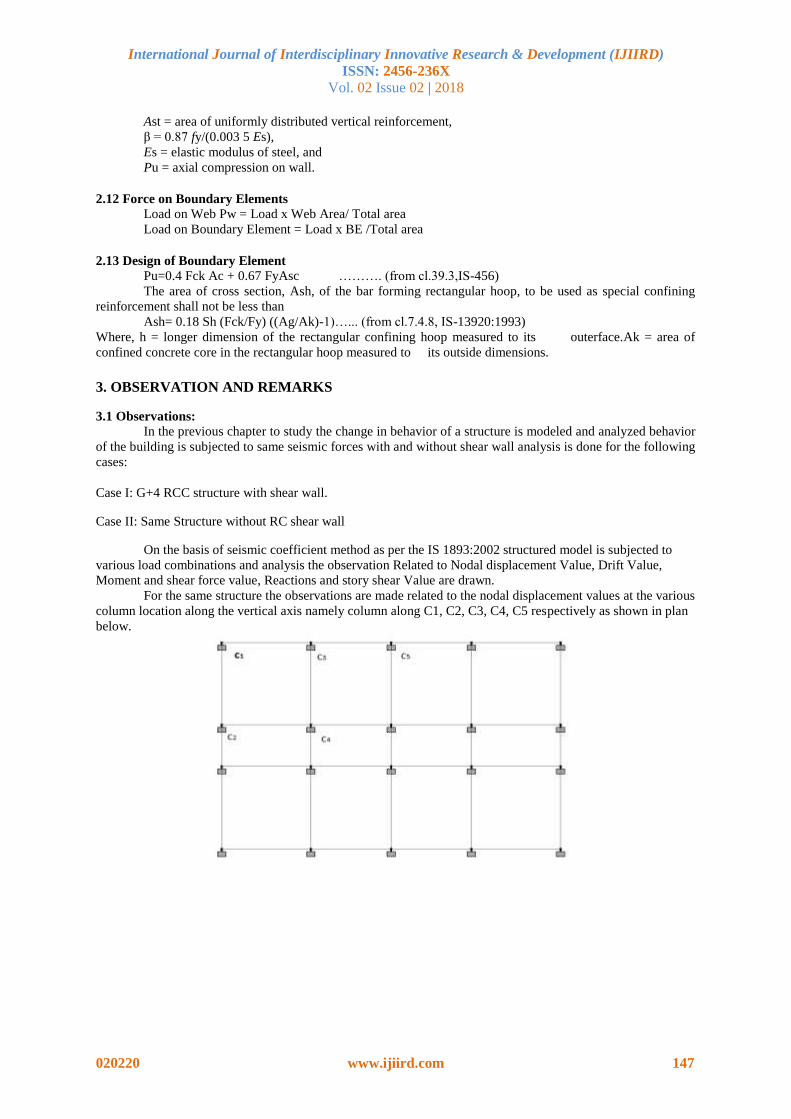
3. OBSERVATION AND REMARKS
3.1 Observations:
In the previous chapter to study the change in behavior of a structure is modeled and analyzed behavior
of the building is subjected to same seismic forces with and without shear wall analysis is done for the following
cases:
Case I: G+4 RCC structure with shear wall.
Case II: Same Structure without RC shear wall
On the basis of seismic coefficient method as per the IS 1893:2002 structured model is subjected to
various load combinations and analysis the observation Related to Nodal displacement Value, Drift Value,
Moment and shear force value, Reactions and story shear Value are drawn.
For the same structure the observations are made related to the nodal displacement values at the various
column location along the vertical axis namely column along C1, C2, C3, C4, C5 respectively as shown in plan
below.
International Journal of Interdisciplinary Innovative Research & Development (IJIIRD)
ISSN: 2456-236X
Vol. 02 Issue 02 | 2018
020220 www.ijiird.com 148
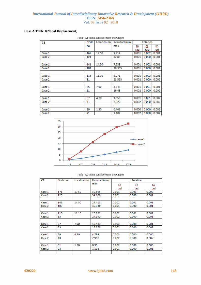
Case A Table 1(Nodal Displacement)
Table- 3.1 Nodal Displacement and Graphs
Table- 3.2 Nodal Displacement and Graphs

International Journal of Interdisciplinary Innovative Research & Development (IJIIRD)
ISSN: 2456-236X
Vol. 02 Issue 02 | 2018
020220 www.ijiird.com 149
Table 2(Drift Values)
Table -3.3 Drift Values and Graphs

International Journal of Interdisciplinary Innovative Research & Development (IJIIRD)
ISSN: 2456-236X
Vol. 02 Issue 02 | 2018
020220 www.ijiird.com 150
Table -6.10 Drift Values and Graphs
Table 3(Base Shear Forces)
International Journal of Interdisciplinary Innovative Research & Development (IJIIRD)
ISSN: 2456-236X
Vol. 02 Issue 02 | 2018
020220 www.ijiird.com 151
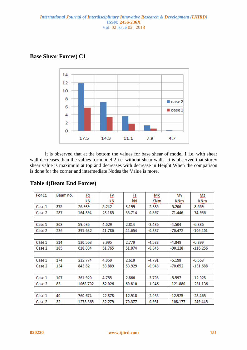
Base Shear Forces) C1
It is observed that at the bottom the values for base shear of model 1 i.e. with shear
wall decreases than the values for model 2 i.e. without shear walls. It is observed that storey
shear value is maximum at top and decreases with decrease in Height When the comparison
is done for the corner and intermediate Nodes the Value is more.
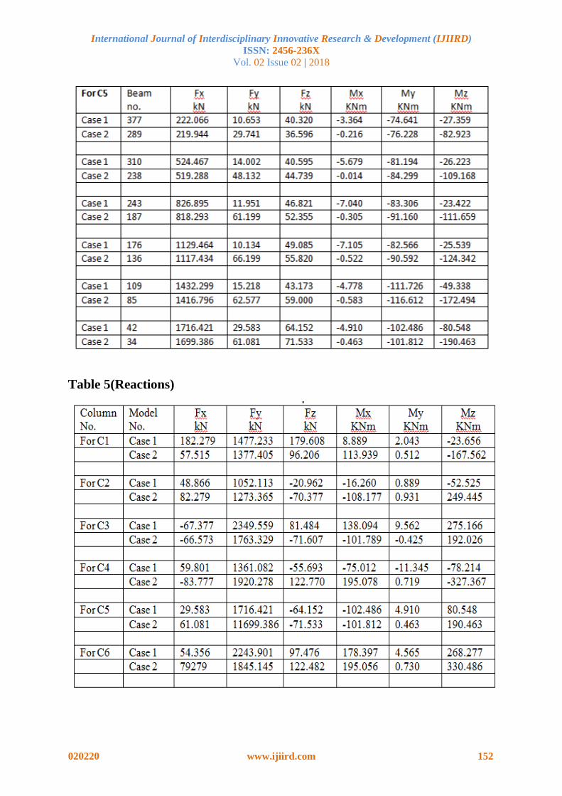
Table 4(Beam End Forces)
International Journal of Interdisciplinary Innovative Research & Development (IJIIRD)
ISSN: 2456-236X
Vol. 02 Issue 02 | 2018
020220 www.ijiird.com 152
Table 5(Reactions)
International Journal of Interdisciplinary Innovative Research & Development (IJIIRD)
ISSN: 2456-236X
Vol. 02 Issue 02 | 2018
020220 www.ijiird.com 153
REFERENCES
1. Khushboo K. Soni1, Dr. Prakash S. Pajgade2. (2015). Design of Multistoried Regular R.C. Buildings
With and Without Shear Walls International Journal of Advance Engineering and Research Development
Volume 2,
2. Ms Deepika C. Hiwrale 1, Prof. P.S. Pajgade 2 (2012) Analysis and Design of of Scientific &
Engineering Research Volume 3, Issue 6, June-2012 1 ISSN 2229-5518
3. M. Samadzad3 and S.R. Mirghaderi (2008)Study of Structural RC Shear Wall System in a56-Story RC
Tall Building The 14thWorld Conference on Earthquake EngineeringOctober 12-17, 2008, Beijing, China
4. M.S.R. Labafzadeh 1 and M. Ziyaeifar2 (2008) seismic behavior of rc dual ductility mode shear walls
The 14thWorld Conference on Earthquake Engineering October 12-17, 2008, Beijing, China
5. Dr. Suresh Borra1, P.M.B.RajKiran Nanduri (2015) Design Method of Reinforced Concrete Shear
Wall Using EBCS American Journal of Engineering Research (AJER) e-ISSN : 2320-0847 p-ISSN : 2320-0936
Volume-4, Issue-3, pp-31-43
6. Varsha R. Harne (2014) Comparative Study of Strength of RC Shear Wall atDifferent Location on
Multi-storied Residential BuildingInternational Journal of Civil Engineering Research.ISSN 2278-3652 Volume
5, Number 4 (2014), pp. 391-400
7. Mohdatif1,prof.laxmikant.vairagade (2015) comparative study on seismic analysis of multistorey
building stiffened with bracing and shear wall. International research journal of engineering and technology
(irjet) e-issn: 2395-0056 volume: 02 issue:
8. Chandurkar(2015). Seismic BehaviourOf Soft StoreyRC Building During Earthquake. International
Journal On Recent AndInnovation Trends In Computing And Communication. ISSN: 2321-8169 Volume: 3
Issue: 2 154 – 158.
9. MohdZulhamAffandiMohdZahida(2013) An Evaluation Of Overstrength Factor Of Seismic Designed
Low Rise RC Buildings. Procedia Engineering 53. 48 – 51.
10. Dr. MizanDoğan, Dr. NevzatKiraç (2002) Soft-StoreyBehaviourIn An Earthquake And Samples Of
Izmit-Duzce. Ecas.
11. AnkitaPramodShelke(2015) Survey Paper OnSeismic Analysis Of Low-Rise Soft Storey Frame
Building. ISSN 2250-2459, ISO 9001:2008 Certified Journal, Volume 5, Issue6.
12. LipikaHalder(2015) Seismic Damage Evaluation Of Gravity Load Designed Low Rise RC Building
Using Non-Linear Static Method. Procedia Engineering 144. 1373 – 1380.
13. MangulkarMadhuri.N. (2012) Structural Response Of Soft Story-High Rise Buildings Under Different
Shear Wall Location Volume 3, Issue 2, Pp. 169-180.
14. Gaurav Joshi (2013) Seismic Analysis Of Soft Storey Buildings Considering Structural And
Geometrical Parameters Vol. 1, No. 2,Pp. 73–84.
15. HamdyAbou-Elfath(2016) Upgrading The Seismic Capacity Of Existing RC Buildings Using Buckling
Restrained Braces, Alexandria Engineering Journal.
16. Danish Khan(2016) Nonlinear Seismic Analysis Of Masonry Infill RC Buildings With Eccentric
Bracings At Soft Storey Level, WMCAUS, Procedia Engineering 161,Pp 9 – 17.
17. Achyut S. Naphade(2015) Pushover Analysis Of RCC Building With Soft Storey At
Differentlevels,IOSR-JMCE, E-ISSN : 2278-1684, P-ISSN : 2320–334X PP 100-108.
18. Pramod M Gajbe(2016) Analysis Of Soft Story Multistored Steel Structure Building, IJESRT, ISSN:
2277-9655.
19. Rahiman G. Khan (2013) Push Over Analysis Of Tall Building With Soft Stories At Different Levels,
IJERA, ISSN: 2248-9622,Vol. 3, Issue 4,Pp.176-185.
20. ShivaniPyasi(2015) Seismic Analysis Of Unsymmetrical (G+10) Multi-StoreyRc Building With Two
Soft Storey At Varying Floors In Medium Soil, IRJET, E-ISSN: 2395-0056, Volume: 02 Issue: 07, P-ISSN:
2395-0072.
21. DevendraDohare(2014) Seismic Behavior Of Soft StoreyBuilding :A Critical Review, International
Journal Of Engineering Research And General Science Volume 2, Issue 6, ISSN 2091-2730.
22. HamdyAbou-Elfath(2016) Upgrading The Seismic Capacity Of Existing RC Buildings Using Buckling
Restrained Braces, Alexandria Engineering Journal.
23. L. Teresa Guevara-Perez(2012)“Soft Story” And “Weak Story” In Earthquake Resistant Design: A
Multidisciplinary Approach, 15 WCEE,LISBOA.
24. Marco Valent(2013) Improving The Seismic Performance Of Precast Buildings Using Dissipative
Devices, ELSEVIER, Procedia Engineering 54, 795 – 804.
25. Hiten L. Kheni(2014) Seismic Response Of RC Building With Soft Stories, (IJETT) – Volume 10.
International Journal of Interdisciplinary Innovative Research & Development (IJIIRD)
ISSN: 2456-236X
Vol. 02 Issue 02 | 2018
020220 www.ijiird.com 154
26. Umesh P. Patil(2015) Analysis Of G+15 Rcc And Composite Structure Having A Soft Storey At
Ground Level By Response Spectrum And Equivalent Static Methods Using Etabs 2013, IRJET, E-ISSN: 2395
-0056, Volume: 02, P-ISSN: 2395-0072.
27. Astaneh-Asl, A., (2001), "Seismic Behavior and Design of Steel Shear Walls-SEONCSeminar", Paper
Distributed and presented at the 2001 SEOANC Seminar, StructuralEngineers Assoc. of Northern California,
November 7, 2001, San Francisco.
28. Vipin V. Halde(2015) Review On Behavior Of Soft Storey In Building, IRJET, E-ISSN: 2395 -0056,
Volume: 02 , P-ISSN: 2395-0072.
29. Bowang Chen(2011) An Improved Simulation Model Of Shear Wall StructuresOf Tall Building,
Science Direct, Procedia Engineering 12, 127–132.
30. Mahmood Hosseini(2011) Comparing The Nonlinear Behaviors Of Steel And Concrete Link Beams In
Coupled Shear Walls System By Finite Element Analysis, Science Direct, Procedia Engineering 14 , 2864–
2871.
31. C.J. Gan(2008) Seismic Behavior Of Steel Plate Reinforced Concrete Shear Walls, 14 Wcee. , Volume:
02 , P-ISSN: 2395-0072
32. Yaseer Alashkar(2014) A Comparative Study Of Seismic Strengthening Of RC Buildings By Steel
Bracings And Concrete Shear Walls, Journal Of Civil And Structural Engineering Research, ISSN, 2348-7607,
Vol. 2, Issue 2, Pp: (24-34),
33. Ourdia Bélaidia *, Madjid Almansbaa (20150Comparative study on the behavior of slender RC walls
with two methods of reinforcement, 1st International Conference on Structural Integrity Procedia Engineering
114 ( 2015 ) 298 – 305
34. Abhishek Arora(2015) Alternative Approach To Soft Storey In Seismic Analysis Of R.C.C Building
Structures, SSRG-IJCE, EFES.
35. TarunShrivastava(2015) Earthquake Analysis Of Multi-Storey Structure With Different Location Of
Shear Wall With Response Spectrum Method Using Hand Method, ISSN 2250-2459, ISO 9001:2008, IJETAE,
Volume 5, Issue 1.
36. SnehalKaushik(2016) Seismic Damage In Shear Wall-Slab Junction In RC Buildings, ICOVP,
Procedia Engineering 144, 1332 – 1339.
Copyright © 2022 FDOKUMEN