Ultimate behavior of axially loaded RC wall-like columns confined with GFRP
9
Ultimate behavior of axially loaded RC wall-like columns confined with GFRP Andrea Prota * , Gaetano Manfredi, Edoardo Cosenza Department of Structural Analysis and Design, University of Naples Federico II, Via Claudio 21, 80125 Naples, Italy Received 16 May 2005; received in revised form 16 January 2006; accepted 26 January 2006 Available online 23 March 2006 Abstract The assessment of the effectiveness of the fiber reinforced polymer (FRP) confinement on rectangular reinforced concrete (RC) col- umns with high aspect ratio (wall-like) still represents an unresolved issue. The present paper aims at providing more experimental evi- dence about the behavior of such members confined with both uni-directional and quadri-directional glass FRP laminates. Particular attention is devoted to issues related to the premature failure of confining fibers experimentally observed in wall-like columns. Test results on nine axially loaded columns are herein presented; emphasis is also given to the analysis of FRP strain profiles along the sides of the cross-section. The analysis of test results highlights that glass FRP (GFRP) confinement could determine significant strength and duc- tility increases; the discussion of failure modes points out that the failure of GFRP confined wall-like columns is controlled by the shape of the cross-section and occurs at transverse strains in the jacket much lower than those ultimate of the fibers. Theoretical–experimental comparisons are performed using some available models for strength prediction of such members. Ó 2006 Elsevier Ltd. All rights reserved. Keywords: A. Glass fibers; B. Strength; C. Analytical modelling; D. Mechanical testing 1. Introduction The external confinement of RC columns is one of the most common applications of FRP composites in construc- tion. Such solution provides a sound technique for upgrad- ing both building columns and bridge piers as it ensures an easy and fast installation, strength and/or ductility increase, high durability, low impact on the use of the structure, almost no increase of mass and geometrical dimen- sions of the cross-sections. The confining action of FRP jackets gives the best performance on circular columns, whose geometrical configuration allows the fibers to be effective on the entire cross-section. In these cases, the fail- ure of the member is generally due to the attainment of the ultimate strains of the FRP jacket, whose effectiveness is maximum. A different behavior characterizes square and rectangular columns where, due to the presence of the corners, a part of the cross-section remains unconfined. Similarly to the confinement with steel hoops, that loss of effectiveness is generally modeled with parabolic areas defined by the corners and eventually by longitudinal steel bars [1]. The failure of the member can occur when the strains in the FRP laminate are lower than the ultimate; this is due to the stress concentration around the corners. The FRP confining system is less effective than on a circu- lar member and its effectiveness depends on the ratio between the sides of the cross-section. This aspect is still under discussion by researchers and is clearly presented in Mukherjee et al. [2] along with other complicating effects related to the mechanical behavior of FRP wrapped con- crete columns. In particular, in the case of wall-like columns (ratio between sides higher than about 3), the experimental evi- dence highlighted that the effectiveness of the FRP jacket was even more reduced; the failure of the member occurred at FRP strains far lower than the ultimate, and a full the- oretical understanding of the collapse mode was not 1359-8368/$ - see front matter Ó 2006 Elsevier Ltd. All rights reserved. doi:10.1016/j.compositesb.2006.01.005 * Corresponding author. Tel.: +39 081 7683534; fax: +39 081 7683491. E-mail address: [email protected] (A. Prota). www.elsevier.com/locate/compositesb Composites: Part B 37 (2006) 670–678
Transcript of Ultimate behavior of axially loaded RC wall-like columns confined with GFRP

www.elsevier.com/locate/compositesb
Composites: Part B 37 (2006) 670–678
Ultimate behavior of axially loaded RC wall-like columnsconfined with GFRP
Andrea Prota *, Gaetano Manfredi, Edoardo Cosenza
Department of Structural Analysis and Design, University of Naples Federico II, Via Claudio 21, 80125 Naples, Italy
Received 16 May 2005; received in revised form 16 January 2006; accepted 26 January 2006Available online 23 March 2006
Abstract
The assessment of the effectiveness of the fiber reinforced polymer (FRP) confinement on rectangular reinforced concrete (RC) col-umns with high aspect ratio (wall-like) still represents an unresolved issue. The present paper aims at providing more experimental evi-dence about the behavior of such members confined with both uni-directional and quadri-directional glass FRP laminates. Particularattention is devoted to issues related to the premature failure of confining fibers experimentally observed in wall-like columns. Test resultson nine axially loaded columns are herein presented; emphasis is also given to the analysis of FRP strain profiles along the sides of thecross-section. The analysis of test results highlights that glass FRP (GFRP) confinement could determine significant strength and duc-tility increases; the discussion of failure modes points out that the failure of GFRP confined wall-like columns is controlled by the shapeof the cross-section and occurs at transverse strains in the jacket much lower than those ultimate of the fibers. Theoretical–experimentalcomparisons are performed using some available models for strength prediction of such members.� 2006 Elsevier Ltd. All rights reserved.
Keywords: A. Glass fibers; B. Strength; C. Analytical modelling; D. Mechanical testing
1. Introduction
The external confinement of RC columns is one of themost common applications of FRP composites in construc-tion. Such solution provides a sound technique for upgrad-ing both building columns and bridge piers as it ensuresan easy and fast installation, strength and/or ductilityincrease, high durability, low impact on the use of thestructure, almost no increase of mass and geometrical dimen-sions of the cross-sections. The confining action of FRPjackets gives the best performance on circular columns,whose geometrical configuration allows the fibers to beeffective on the entire cross-section. In these cases, the fail-ure of the member is generally due to the attainment of theultimate strains of the FRP jacket, whose effectiveness ismaximum. A different behavior characterizes square andrectangular columns where, due to the presence of the
1359-8368/$ - see front matter � 2006 Elsevier Ltd. All rights reserved.
doi:10.1016/j.compositesb.2006.01.005
* Corresponding author. Tel.: +39 081 7683534; fax: +39 081 7683491.E-mail address: [email protected] (A. Prota).
corners, a part of the cross-section remains unconfined.Similarly to the confinement with steel hoops, that loss ofeffectiveness is generally modeled with parabolic areasdefined by the corners and eventually by longitudinal steelbars [1]. The failure of the member can occur when thestrains in the FRP laminate are lower than the ultimate;this is due to the stress concentration around the corners.The FRP confining system is less effective than on a circu-lar member and its effectiveness depends on the ratiobetween the sides of the cross-section. This aspect is stillunder discussion by researchers and is clearly presentedin Mukherjee et al. [2] along with other complicating effectsrelated to the mechanical behavior of FRP wrapped con-crete columns.
In particular, in the case of wall-like columns (ratiobetween sides higher than about 3), the experimental evi-dence highlighted that the effectiveness of the FRP jacketwas even more reduced; the failure of the member occurredat FRP strains far lower than the ultimate, and a full the-oretical understanding of the collapse mode was not

A. Prota et al. / Composites: Part B 37 (2006) 670–678 671
achieved. The experimental activity presented in this paperwas set-up with the purpose of focusing the attention onthese unresolved issues and providing further experimentalevidence to validate the theoretical predictions.
The topic of confinement of non-circular columns stillrepresents an unresolved issue even in terms of code provi-sions [3,4]. The ACI 440.2R-02 Guide [3] deals with theFRP confinement by distinguishing strength and ductilityissues. Even though tests have shown the capacity ofFRP jackets to increase the axial compression strength ofsquare and rectangular members, the ACI guide does notprovide any suggestion about how such increase could becomputed. Design criteria are indeed provided in order toevaluate the ductility improvement that FRP jackets candetermine on square and rectangular cross-sections.According to this guide, the FRP benefit in terms of ductil-ity should be neglected if the aspect ratio (i.e. ratio betweenwidth and height of the cross-section) is more than 1.5 or ifone of the two sides is longer than 900 mm. In these cases,it is recommended to consider the confining action of com-posites only if specific tests confirm their effectiveness.
The fib bulletin 14 [4] provides a procedure for comput-ing the increase in load-carrying capacity due to the FRPconfinement of square and rectangular columns. Themethod is based on modeling the effect of the externaljacket by parabolic areas with initial tangent at 45� andthen calculating two lateral confining pressures along thedirections parallel to the sides. It is recognized that the duc-tility can also be improved. No limitation for the given for-mulas is suggested in the bulletin with respect to the aspectratio on non-circular cross-sections.
Experimental tests have been also performed to assessthe effectiveness of FRP jacketing of wall-like columnsunder pure axial load [5–7]. Tanwongsval et al. [5]tested five wall-like RC columns having cross-section115 mm · 420 mm and being 1.5 m high; the longitudinalsteel ratio was equal to 2.8%. Columns were externallybonded with GFRP laminates; the opportunity of install-ing the FRP after enlarging the cross-section with twosemi-cylindrical portions made of high strength mortarwas explored. The effect of the strengthening under sus-tained loads was also investigated. Tan [6] carried out anexperimental investigation on 52 RC columns character-ized by cross-section dimensions equal to those of the pre-vious study. The majority of the specimens were 1.5 mhigh, while some had height equal to 1.2 m; the longitudi-nal steel ratio was equal to 2.2%. Both glass (GFRP) andcarbon (CFRP) laminates with uni-directional fiber texturewere used to externally bond the axially loaded members;the influence of plaster finishes and fiber anchors was alsoinvestigated. Hosny et al. [7] tested 12 RC rectangular col-umns with cross-section of 150 mm · 450 mm and heightequal to 1.5 m. The longitudinal steel ratio was equal to1%. The axially loaded members were confined usingCFRP strips; the possibility of improving the effectivenessof the system by CFRP anchors and steel plates was alsoinvestigated. All these tests confirmed that the failure was
premature and occurred at FRP strains lower than ultimatevalues.
This paper deals with an experimental and theoreticalanalysis on RC wall-like columns with cross-section identi-cal to those considered in [5,6]. It focuses on wall-like col-umns subjected only to axial load because similar membersare often present in dual frame systems used in earthquakeresistant structures [8]. When such structural type isadopted, the analysis of wall-like columns is basic as thecapacity of the dual system is strongly dependent onthe performance of those elements under compression.The main objectives of this work can be summarized asfollows: to understand the effectiveness and the limitationsof external confinement with respect to cross-section geom-etry; to assess the effectiveness of multi-directional fibertextures in order to improve both strength and ductility;to verify the opportunity of using high density GFRP jack-ets that could boost the structural performance by delayingfailure modes related to buckling of longitudinal steelbars; to identify the parameters governing the amount ofimprovement achievable by a FRP wrapping; to assesswhether the FRP wrapping could enable uni-directionalFRP laminates parallel to the member axis to provide acontribution to its compressive strength; to provide moreexperimental data that could be used to confirm some con-clusions obtained on the base of a limited number of tests[5,6]; to validate theoretical models developed by Tan [6]and Maalej et al. [9] for this particular class of columns.
2. Experimental program
The experimental program was based on tests on rectan-gular columns with cross-section 115 mm · 420 mm, andheight equal to 1.5 m. The longitudinal steel reinforcementwas given by a total of 4 D12 e 4 D14 deformed bars yield-ing a geometric percentage of steel equal to 2.2%. Steel barsD6 spaced at 100 mm on center were used for the trans-verse reinforcement; as typically done for cross-sectionswith high aspect ratio, transverse links were used to ensurethe effectiveness of the steel stirrups. Forms used to cast thespecimens were shaped in order to have a corner radius, R,of 20 mm; even though in real situations rounding of cor-ners has to be done on the existing members, this detailwas already taken care during the construction in orderto make it easer and faster the installation of FRP lami-nates. At top and bottom of each specimen two bulbs withcross-section 700 mm · 350 mm, 250 mm high, were real-ized in order to ensure a proper distribution of the axialload. Information about specimens geometry and rein-forcement are depicted in Fig. 1.
According to the test plan, each configuration should berepeated three times in order to verify the consistency ofexperimental outcomes. At date, a total of nine columnshas been tested. Three control columns have been tested(namely, V-1, V-2 and V-3). The remaining six columnshave been strengthened with GFRP laminates in the direc-tions both parallel and perpendicular to the member axis.

2 D14 + 2 D122 D12
2 D14
2 D12
5 stirrups D12
2 stirrups D12
A A
stirrups D6/100 mm
2 D14
2 stirrups D12
4 stirrups D12
A A
2 D14 + 2 D12
stirrups D6/100 mm
ELEVATION VIEW
2000
1500
250
250
700 350
R20
SECTION A-A
2 stirrups D6/10 mm
2 D14
2 D12
117.
5
350
117.
511
5
140 420 140
700
Fig. 1. Specimens geometry and internal reinforcement.
672 A. Prota et al. / Composites: Part B 37 (2006) 670–678
For all of them, first two plies of C-shaped uni-directionalGFRP laminates have been installed along the height; theyhave been bonded on the two short sides of the columnsand extended on the long sides for a length of 75 mm (Figs.2 and 3). This layout was expected to provide a strengthcontribution equal to about 5% of the compressive strengthof the control columns according to the design based on thefollowing assumptions: GFRP wrapping is able to preventthe buckling of these laminates [6], thus their contribu-tion to the compressive strength of the member can beaccounted for; compatibility with concrete governs thevalue of GFRP ultimate compressive strain assumed equalto 0.2% (i.e. design ultimate strain for concrete under purecompression). The assessment of the validity of theseassumptions was identified as an important task in orderto eventually suggest to update existing code recommenda-
1500
C-shaped uni-directional laminates
Fibe
r or
ient
atio
n in
th
e lo
ngit
udin
al p
lies
Fig. 2. Layout of the C-shaped longitudinal GFRP laminates.
Fig. 3. Installation of a C-shaped longitudinal GFRP laminate.
tions [3,4] that do not account for the contribution of FRPin compression. After the installation of the C-shaped lam-inates, the GFRP strengthening in the direction perpendic-ular to the member axis has been carried out by installingtwo plies of uni-directional GFRP (namely UN2-1 andUN2-2) (Fig. 4a), three plies of uni-directional GFRP(namely UN3-1, UN3-2 and UN3-3) (Fig. 4a), or two pliesof quadri-directional GFRP laminates (namely Q2-1)(Fig. 4b). For instance, the installation of the second plyof transverse GFRP laminates on specimen UN3-1 isdepicted in Fig. 5.
Two different batches of concrete were needed in orderto build the nine specimens; the compressive concretestrength obtained from cylinders at the time of columntests ranged between 15 and 18 MPa, as reported in Table1. A low concrete strength was selected in order to repro-duce typical conditions of many existing buildings charac-terized by poor quality of the original construction and

Fiber orientation in the transverse plies
Overlap length oftransverse laminates
1500
300
500
70
600
300
7060
1500
Overlap length of transverse laminates
Fiber orientation in the transverse plies
250
4040
250
250
4040
4050
250
250
250
250
(a) (b)
Fig. 4. Layout of transverse GFRP laminates: uni-directional (a) and quadri-directional (b).
Fig. 5. Installation of the second ply of transverse GFRP laminates onspecimen UN3-1.
Table 1Strength and axial deformation of tested specimens
Specimen fc (MPa) Ultimate load (kN) Strength increase(%)
V-1 15 1070.33 – –V-2 15 1049.55 –V-3 15 986.50 –UN2-1 18 1500.34 + 44.9 +UN2-2 18 1649.58 + 59.3UN3-1 15 1386.72 + 33.9 +UN3-2 15 1388.32 + 34.1UN3-3 15 1348.03 + 30.2Q2-1 18 1559.24 + 49.9 +
A. Prota et al. / Composites: Part B 37 (2006) 670–678 673
consequent deterioration over the years. These are thestructures that actually more need to be strengthened andsuch strengthening can be done using composite materials.The yielding stress of the longitudinal steel bars wasfound to be equal to about 500 MPa. The uni-directionalGFRP laminates had density of 900 g/m2, thickness of0.354 mm/ply, modulus of elasticity equal to 65.6 GPaand ultimate tensile strain equal to 2.1%. The quadri-direc-tional GFRP laminates had density of 1130 g/m2, thicknessof 0.444 mm/ply, modulus of elasticity equal to 65.6 GPaand ultimate tensile strain equal to 2.1%.
The application of the axial force was performed in aload control mode under a machine with capacity up to5000 kN. Specimens were instrumented in order to recordboth displacements and strains. Three LVDTs were used:two were placed parallel to the member axis and recordedthe shortening of columns along the total height of 1.5 m;the third was installed perpendicular to the long sideof the mid-height cross-section in order to monitor whetherany significant out-of-plane displacement occurred. Inaddition, 20 strain gages were installed on the FRP lami-nates in the direction perpendicular to the column axis.
Avg. ult. axial strain (mm/mm) Axial strain increase(%)
0.0030 ––0.0036 –
0.0025 –52.1 0.0042 + 38.5
+ 46.70.0047 + 54.9
33.1 0.00618 + 103.70.00517 + 70.4 + 81.60.00518 + 70.8
49.9 0.0041 + 35.2 + 35.2

4 213
20
97 812 13 14 15 16
5
1819 17
10 11
6
Side A Side B
1500
1200
375
620
Fig. 6. Layout of strain gages on the GFRP wrapping.
0
250
500
750
1000
1250
1500
1750
0.000 0.001 0.002 0.003 0.004 0.005 0.006 0.007
Average axial strain (mm/mm)
Loa
d (k
N)
V-3
UN2-1
UN2-2Q2-1
UN3-2
UN3-3
UN3-1
V-2V-1
Fig. 7. Load-average axial strain.
Fig. 8. Column V-2 after failure.
674 A. Prota et al. / Composites: Part B 37 (2006) 670–678
The strain gages layout was designed in order to record thestrain profiles on both long sides at mid-height and com-pare mid-height readings with those obtained at aboutone-forth of the column close to top and bottom; such lay-out is shown in Fig. 6.
3. Test results
The GFRP strengthening generated significant strengthincreases (Table 1). Tests on the three un-strengthened col-umns provided an average ultimate axial load equal to1035.46 kN. With respect to such average value, the appli-cation of three plies of GFRP laminates determined astrength increase ranging between 30.2% (i.e. UN3-3) and33.9% (i.e. UN3-1). A significant strength improvementalmost equal to 50% was achieved by installing two pliesof quadri-directional laminates (i.e. Q2-1). The columnsstrengthened with two plies showed a strength increaseranging between 44.9% (i.e. UN2-1) and 59.3% (i.e.UN2-2), but this is related to an higher concrete strengthcompared to other columns (17 MPa versus of 15 MPa)(Table 1).
Axial strains were obtained by dividing measurements ofthe two longitudinal LVDT transducers over the gagelength of 1.5 m. Average values corresponding to the ulti-mate load of each specimen are summarized in Table 1.Un-strengthened columns failed at ultimate average axialstrains ranging between 0.0025 and 0.0030. An increaseranging between 35.2 and 54.9% was observed on columnsstrengthened with two plies (i.e. UN2-1, UN2-2 and Q2-1),while an improvement larger than 70.4% was achieved with
three plies. Load-average axial strain curves for tested col-umns are depicted in Fig. 7 that shows a very similarbehavior of all specimens up to a load of about 250 kN.Then, the unstrengthened columns and those jacketed withthree plies of GFRP laminates are less stiff than the remain-ing; this could be explained by considering the difference inconcrete quality that affects the post-cracking behavior.
The failure of the three unstrengthened columns wasidentical and occurred very close to mid-height. As theaverage axial strain approached the ultimate strain of theunconfined concrete, the cover started crushing on one ofthe two long sides of the cross-section. The longitudinalsteel bars bulged within the spacing between two consecu-tive stirrups and determined the spalling of the concretecover; at that stage the column became unable to carry fur-ther load. Fig. 8 shows column V-2 after failure. The failureof all strengthened columns was similar to that of thoseunstrengthened; it occurred again at a cross-section closeto the mid-height. The externally bonded reinforcementdid not allow following what happened to the concretemember; however, the bulging of the FRP laminates

A. Prota et al. / Composites: Part B 37 (2006) 670–678 675
occurred at the location of the failed cross-section. Basedon what was observed on unstrengthened specimens, theprogress to failure of strengthened specimens could havebeen as follows: crushing of the concrete cover at an aver-age axial strain of about 0.003, bulging of longitudinal steelbars, spalling of concrete cover pushing against the exter-nally bonded jacket; bulging of such FRP jacket. Fig. 9depicts column UN2-1 at failure.
Strains on the externally bonded laminates recorded atfailure are summarized in Table 2; strain numbers referto the layout reported in Fig. 6. In addition to the valuesprovided at ultimate by the twenty gages, the table reportsaverage values and the standard deviations, respectively.For the five specimens bonded with uni-directional lami-nates, average ultimate strains range between about 0.08
Fig. 9. Failure of column UN2-1.
Table 2Percent strains of the GFRP laminates at column failure
Strain gage UN2-1 UN2-2 UN3-1 UN3-2 UN3-3 Q2-1
1 0.0166 0.1446 0.0820 0.1290 0.0721 0.05952 0.0710 0.0954 0.0485 0.0932 0.0412 0.07553 –* 0.0951 0.0804 0.1521 0.0448 0.15004 –* 0.0913 –* 0.1138 0.0708 0.14705 0.0432 –* 0.1034 0.1294 –* 0.14756 –* –* 0.0964 0.1562 0.1105 0.29367 –* 0.1975 0.0892 0.0743 –* 0.12508 –* 0.1836 0.0785 0.0901 0.0535 0.11379 –* 0.1727 0.0491 0.0814 0.0665 0.103810 –* 0.1356 0.0643 0.1020 0.0477 0.106511 –* 0.0696 0.1019 0.0959 0.0694 0.134012 0.1682 0.0866 0.0858 0.3205 0.2025 0.161713 –* 0.1321 0.0697 0.0684 0.0838 0.505114 0.0829 0.1388 0.0906 0.0880 0.0955 0.437415 0.0793 0.1081 0.0839 0.1099 0.0894 0.584216 0.0989 0.1577 0.1048 0.1536 0.1974 0.230917 0.1392 0.1135 0.0919 0.1010 0.0637 0.083318 –* 0.0343 0.0862 0.1025 0.0520 0.119219 0.0768 0.1091 0.0496 0.0804 0.0789 0.113520 –* 0.1138 –* –* 0.1452 0.1467Average 0.0862 0.1211 0.0809 0.1180 0.0881 0.1919S. dev. 0.00046 0.00041 0.00018 0.00056 0.00048 0.00148
* Not available.
and 0.12%; an average value of about 0.19% is given bythe column jacketed with quadri-axial laminates (i.e. Q2-1). Values of the standard deviation highlight that thestrain distribution along the perimeter of the cross-sectionis more uniform for uni-directional laminates than forquadri-directional (Table 2). In all cases, peak ultimatestrains far beyond the average values have been recordedby strain gages 6, 7, 12 and 16, located close to the cornersof the cross-section. Such strain concentrations startedalready at loads much lower than the ultimate as demon-strated, for instance, by typical strain trends along the sidesshown in Fig. 10. In the cases of specimens UN2-2 and Q2-1, there is a concentration of high strains on one of the twolong sides that is consistent with the actual failure modeinducing the bulging of the composite jacket just on thatside (i.e. strain gages 7, 8 and 9 for UN2-2 and 13, 14, 15and 16 on Q2-1). Peak values up to 0.32% were recordedwhen uni-directional laminates were used (i.e. strain gage12 in UN3-2), while strains of the laminate up to 0.58%were recorded on specimen Q2-1 (i.e. strain gage 15).
4. Discussion of test results
The analysis of test results both obtained within thisresearch and by other researchers highlights that the shapeof the cross-section strongly limits the capability of theexternally bonded composite reinforcement to improvethe ultimate performances of strengthened wall-likemembers.
As far as strength issues are concerned, the results of thepresent study point out that the strength increase achiev-able by means of FRP jacketing could be very significant.It is observed that the addition of further transverse FRPplies does not necessarily imply an increase of strength,which sometimes could even be reduced. Considering thestrength of the two concrete batches, it can be noted thatthe percent strength gain for UN2 specimens is about equalto that of UN3. UN2 and UN3 series show an averageincrease equal to 52.1 and 33.1%, respectively, and this dif-ference (about 19%) is very close to that between the twoconcrete strength (about 20%) (Table 1). This is consistentwith what was already highlighted by other studies [5–7]and is due to the fact that the FRP jacket is unable to mod-ify the described failure mode controlled by the shape ofthe cross-section. Such aspect was also evidenced by theexperimental study conducted by Tan [6]; Table 3 summa-rizes, with the specimen codes used by that author, only thecolumns where the number of transverse plies was changed.Values reported in the table confirm that, in some cases, theaddition of FRP in the transverse direction caused a reduc-tion of the bearing capacity of the member.
Whereas this happens for the strength, the addition oftransverse FRP plies determines significant benefits on theductility expressed in terms of average axial strain. This isdemonstrated by comparing the performance of the twocolumns of series UN2 to that of the three of series UN3(Table 1); such fact was already highlighted in previous

Table 3Influence of number of transverse FRP plies [6]
Series Column Longitudinal plies Transverse plies Type of fibers Ultimate load (kN)
K K11G 1 1 GFRP 1654K12G 2 1835K11GP 1 1 1906K12GP 2 1894
H H22G-1 2 2 GFRP 1270H23G-1 3 1260
M M12G 1 2 GFRP 1664M13G 3 1565M21GP 2 1 GFRP 1670M23GP 3 1869
S S12C 1 2 CFRP 1579S13C 3 1586
U U11C 1 1 CFRP 1297U12C 2 1608
0.00050.000
0.0010.00150.0020.00250.0030.0035
12 13 14 15 16
εUN3-2
141312 1615Strain gage0.000
0.00150.0010.0005
0.00350.0030.00250.002
ε
Strain gage
UN3-3
Fig. 10. Strain profiles at a load of 800 kN.
676 A. Prota et al. / Composites: Part B 37 (2006) 670–678
studies [6,10]. As more transverse plies are added, the stiff-ness of the FRP jacket increases and its action against bothbulging of steel bars and spalling of the concrete coverbecomes stronger. Thus, more axial deformation is neces-sary to attain the failure of the cross-section that is due tothe bulging of the FRP jacket and occurs at a load level sim-ilar to that provided by columns with less transverse plies.
The fact that the failure mode is mainly controlled bythe shape of the cross-section has a consistent consequenceon the values of jacket strains measured at failure of themember. The average GFRP strain of about 0.1% givenby columns wrapped with uni-directional laminates con-firms the value suggested by Tan [6]. That author devel-oped a model for strength prediction of wall-like columnsand indicated that, for design purposes, a value of 0.1%should be used to evaluate the confinement contributionof FRP. Such value is certainly much lower than the ulti-mate strain obtained by tensile tests on GFRP fibers; how-ever, the two values cannot be compared since the failure ofthe FRP jacket on a wall-like column does not occur due tothe fiber breakage, but to the bulging of the composite sys-tem. The higher average ultimate transverse strain mea-sured on the quadri-directional laminates (i.e. Q2-1) isdue to the fact that the amount of transverse fibers of eachquadri-directional ply is slightly larger than half of that of
a uni-directional. Such factor of about two can be found ifone compares values of average and peak strains of col-umns of series UN2 and UN3 with Q2-1 (Table 2).
5. Numerical models
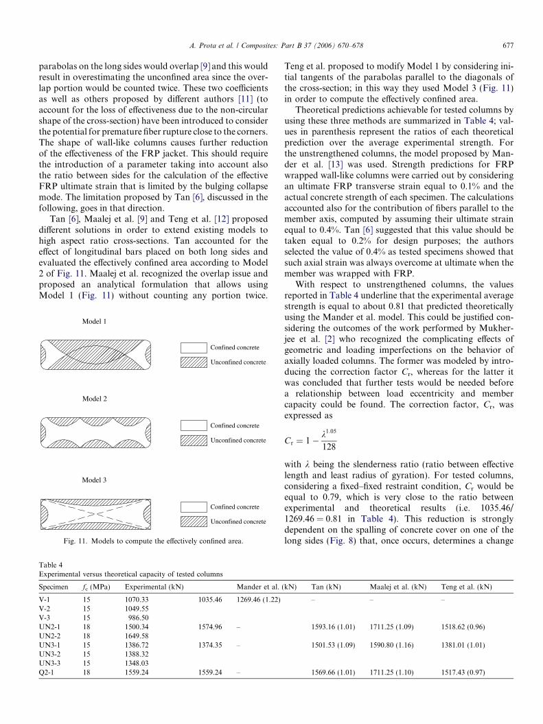
One of the objectives of the present study was to obtainfurther experimental data in order to develop and/or vali-date reliable formulas for the strength prediction of rectan-gular columns wrapped with FRP laminates. The modelsproposed by both ACI [3] and fib [4] guides would computethe effectively confined area by considering on each side ofthe cross-section a parabola with initial tangent slope equalto 45� (Model 1 in Fig. 11). Based on such assumption, if onewere to use the ACI 440.2R-02 formulas, an efficiency factorka equal to 0.004 would have been obtained for the analyzedcross-section. Similarly, by following the fib 14 bulletinapproach, the confinement effectiveness coefficient ke isequal to 0.004. Apart from a slight difference in the nota-tions, both coefficients express the ratio between the effec-tively confined concrete area over the gross concrete areaand are introduced to account for the reduction of the lateralconfining pressure due to the non-circular shape of the cross-section. As Fig. 11 allows observing, this approach cannot beextended to cross-sections of wall-like columns: the two
A. Prota et al. / Composites: Part B 37 (2006) 670–678 677
parabolas on the long sides would overlap [9] and this wouldresult in overestimating the unconfined area since the over-lap portion would be counted twice. These two coefficientsas well as others proposed by different authors [11] (toaccount for the loss of effectiveness due to the non-circularshape of the cross-section) have been introduced to considerthe potential for premature fiber rupture close to the corners.The shape of wall-like columns causes further reductionof the effectiveness of the FRP jacket. This should requirethe introduction of a parameter taking into account alsothe ratio between sides for the calculation of the effectiveFRP ultimate strain that is limited by the bulging collapsemode. The limitation proposed by Tan [6], discussed in thefollowing, goes in that direction.
Tan [6], Maalej et al. [9] and Teng et al. [12] proposeddifferent solutions in order to extend existing models tohigh aspect ratio cross-sections. Tan accounted for theeffect of longitudinal bars placed on both long sides andevaluated the effectively confined area according to Model2 of Fig. 11. Maalej et al. recognized the overlap issue andproposed an analytical formulation that allows usingModel 1 (Fig. 11) without counting any portion twice.
Table 4Experimental versus theoretical capacity of tested columns
Specimen fc (MPa) Experimental (kN) Mander et al. (
V-1 15 1070.33 1035.46 1269.46 (1.22)V-2 15 1049.55V-3 15 986.50UN2-1 18 1500.34 1574.96 –UN2-2 18 1649.58UN3-1 15 1386.72 1374.35 –UN3-2 15 1388.32UN3-3 15 1348.03Q2-1 18 1559.24 1559.24 –
Confined concrete
Unconfined concrete
Confined concrete
Unconfined concrete
Model 1
Model 2
Unconfined concrete
Confined concrete
Model 3
Fig. 11. Models to compute the effectively confined area.
Teng et al. proposed to modify Model 1 by considering ini-tial tangents of the parabolas parallel to the diagonals ofthe cross-section; in this way they used Model 3 (Fig. 11)in order to compute the effectively confined area.
Theoretical predictions achievable for tested columns byusing these three methods are summarized in Table 4; val-ues in parenthesis represent the ratios of each theoreticalprediction over the average experimental strength. Forthe unstrengthened columns, the model proposed by Man-der et al. [13] was used. Strength predictions for FRPwrapped wall-like columns were carried out by consideringan ultimate FRP transverse strain equal to 0.1% and theactual concrete strength of each specimen. The calculationsaccounted also for the contribution of fibers parallel to themember axis, computed by assuming their ultimate strainequal to 0.4%. Tan [6] suggested that this value should betaken equal to 0.2% for design purposes; the authorsselected the value of 0.4% as tested specimens showed thatsuch axial strain was always overcome at ultimate when themember was wrapped with FRP.
With respect to unstrengthened columns, the valuesreported in Table 4 underline that the experimental averagestrength is equal to about 0.81 that predicted theoreticallyusing the Mander et al. model. This could be justified con-sidering the outcomes of the work performed by Mukher-jee et al. [2] who recognized the complicating effects ofgeometric and loading imperfections on the behavior ofaxially loaded columns. The former was modeled by intro-ducing the correction factor Cr, whereas for the latter itwas concluded that further tests would be needed beforea relationship between load eccentricity and membercapacity could be found. The correction factor, Cr, wasexpressed as
Cr ¼ 1� k1:05
128
with k being the slenderness ratio (ratio between effectivelength and least radius of gyration). For tested columns,considering a fixed–fixed restraint condition, Cr would beequal to 0.79, which is very close to the ratio betweenexperimental and theoretical results (i.e. 1035.46/1269.46 = 0.81 in Table 4). This reduction is stronglydependent on the spalling of concrete cover on one of thelong sides (Fig. 8) that, once occurs, determines a change
kN) Tan (kN) Maalej et al. (kN) Teng et al. (kN)
– – –
1593.16 (1.01) 1711.25 (1.09) 1518.62 (0.96)
1501.53 (1.09) 1590.80 (1.16) 1381.01 (1.01)
1569.66 (1.01) 1711.25 (1.10) 1517.43 (0.97)

678 A. Prota et al. / Composites: Part B 37 (2006) 670–678
of the effective concrete area and therefore the load eccen-tricity increases progressively; this influences the capacityin the non-linear field.
Regarding the strengthened columns, Table 4 shows thatthe three considered methods provide ultimate theoreticalloads very close to those measured in the laboratory; the the-oretical contribution of fibers parallel to the member axiswas found to be equal to about 10% of columns strength.Between the three models, that by Teng et al. appears to per-form better predicting the experimental results with a goodlevel of conservativeness. The model by Maalej et al. overes-timates the column capacity in all cases, whereas Tan modelprovides very good predictions for specimens with twotransverse GFRP plies and overestimates by about 9% theaverage result obtained with three plies. In general, the the-oretical models do not overestimate the experimentalstrength as in the case of those unstrengthened and the pre-dictions are indeed quite close to the laboratory results. Theauthors believe that, for strengthened columns, the confin-ing effect of the GFRP jacket delays the spalling of the con-crete cover and the steel rebars buckling, and therefore theinfluence of the imperfections on the global capacity is sig-nificantly reduced. However, they believe that this aspectwill need to be further investigated in the next future.
6. Conclusive remarks
The experimental campaign confirmed that significantstrength increases can be achieved by wrapping RC wall-like columns with GFRP laminates. The number of trans-verse plies does not play a major role in boosting the axialstrength of such members, but it gives important improve-ments in terms of axial ductility. The failure of FRP con-fined wall-like columns is controlled by the shape of thecross-section and determines the bulging of the FRP lami-nates that occurs at fiber strains far below the guaranteedultimate values. The use of a quadri-directional texture doesnot influence the ultimate capacity, even though it allowsfor a failure that, compared to the uni-directional lami-nates, involves a larger portion of the column along itsheight. In addition, since the total density of the quadri-directional is almost equal to that of the uni-directional,its use could ensure the same axial capacity and bring addi-tional benefits to the shear strength of the column; with thesame total amount of material, the quadri-directional couldallow improving both mechanisms by which wall-like col-umns contribute to the seismic strength of dual systems.
In terms of numerical predictions, formulas provided byACI and fib guidelines either cannot be applied or cannot beextended to the case of wall-like columns confined withFRP laminates. In order to achieve reliable strength predic-tions it is necessary to limit the ultimate FRP strain at avalue of 0.1%; this is a fictitious way to account for the bulg-ing of the FRP laminates that characterize the failure ofsuch members. In addition, it is necessary to modify therules generally used for the calculation of the unconfinedarea in order to account for the high ratio between sides.
The comparison with test results highlighted that, withinavailable models for FRP confined wall-like columns, Tenget al. approach allowed for the best predictions of experi-mental results with a good level of conservativeness; Tan’sand Maalej et al. models overestimated slightly and moresignificantly, respectively, the experimental performance.Tests on unstrengthened columns pointed out that geomet-ric imperfections limit the capacity of the member and acorrection factor should be used to match the experimentalvalues; however, the same trend was not found in the case ofFRP strengthened members. Even though this could be jus-tified by considering that the presence of the FRPjacket allow the member to be less influenced by geometricimperfections, this aspect need further investigations.
Acknowledgements
The authors would like to thank MAPEI Spa, Milano,Italy, and Dr A. Balsamo for providing the FRP materialsand supporting the presented experimental research.
References
[1] Realfonzo R, Prota A, Manfredi G, Pecce M. Flexural strength ofFRP-confined RC columns. In: Proceedings CD-ROM of the first fibcongress ‘Concrete structures in the 21st century’, Osaka, Japan;October, 2002. p. 41–50. [Disk B].
[2] Mukherjee A, Boothby TE, Bakis CE, Joshi MV, Maitra SR.Mechanical behavior of fiber-reinforced polymer-wrapped concretecolumns—complicating effects. ASCE J Compos Construct 2004;8(2):97–103.
[3] ACI 440.2R-02. Guide for the design and construction of externallybonded FRP systems for strngthening concrete structures. Reportedby ACI committee 440. American Concrete Institute, FarmingtonHills, MI 48333-9094; 2002. p. 45.
[4] fib Task Group 9.3. Externally bonded FRP reinforcement for RCstructures. International federation for structural concrete, printed bySprint-Digital-Druck, Stuttgart; 2001.
[5] Tanwongsval S, Maalej M, Paramasivam P. Strengthening of RCwall-like columns with FRP under sustained loading. RILEM MaterStruct 2003;36(259):282–90.
[6] Tan KH. Strength enhancement of rectangular RC columns usingFRP. ASCE J Compos Construct 2002;6(3):175–83.
[7] Hosny A, Shaheen H, Abdelrahman A, Elafandy T. Uniaxial tests onrectangular columns strengthened with CFRP. Proceedings of thethird Middle East symposium on structural composites for infra-structure applications, Aswan, Egypt; December 2002.
[8] Balsamo A, Colombo A, Manfredi G, Negro P, Prota A. Seismicbehavior of a full-scale RC frame repaired using CFRP laminates.Eng Struct 2005;27(5):769–80.
[9] Maalej M, Tanwongsval S, Paramasivam P. Modelling of Rec-tangular RC Columns Strengthened with FRP. Elsevier Cem ConcrCompos 2003;25:263–76.
[10] Chaallal O, Shahawy M, Hassan M. Performance of axially loadedshort rectangular columns strengthened with carbon fiber-reinforcedpolymer wrapping. ASCE J Compos Construct 2003;7(3):200–8.
[11] Wang YC. Retrofit of reinforced concrete members using advancedcomposite materials, res. rep., 2000-3, ISSN 0110-3326, University ofCanterbury, NZ (supervised by Restrepo J.I. and Park R.).
[12] Teng JG, Chen JF, Smith ST, Lam L. FRP strengthened RCstructures. Chichester: Wiley; 2002, p. 245.
[13] Mander JB, Priestley MJN, Park R. Theoretical stress–strain modelfor confined concrete. ASCE J Struct Eng 1988;114(8):1824–36.