Numerical analysis of axially loaded circular high strength ...
42
Numerical analysis of axially loaded circular high strength concrete-filled double steel tubular short columns This is the Accepted version of the following publication Ahmed, Mizan, Liang, Qing, Patel, Vipulkumar Ishvarbhai and Hadi, MNS (2019) Numerical analysis of axially loaded circular high strength concrete- filled double steel tubular short columns. Thin-Walled Structures, 138. pp. 105- 116. ISSN 0263-8231 The publisher’s official version can be found at https://www.sciencedirect.com/science/article/pii/S0263823118312023 Note that access to this version may require subscription. Downloaded from VU Research Repository https://vuir.vu.edu.au/37880/
-
Upload
khangminh22 -
Category
Documents
-
view
0 -
download
0
Transcript of Numerical analysis of axially loaded circular high strength ...

Numerical analysis of axially loaded circular high strength concrete-filled double steel tubular short columns
This is the Accepted version of the following publication
Ahmed, Mizan, Liang, Qing, Patel, Vipulkumar Ishvarbhai and Hadi, MNS (2019) Numerical analysis of axially loaded circular high strength concrete-filled double steel tubular short columns. Thin-Walled Structures, 138. pp. 105-116. ISSN 0263-8231
The publisher’s official version can be found at https://www.sciencedirect.com/science/article/pii/S0263823118312023Note that access to this version may require subscription.
Downloaded from VU Research Repository https://vuir.vu.edu.au/37880/
Ahmed, M., Liang, Q. Q., Patel, V. I. and Hadi, M. N. S. (2019). Numerical analysis of axially loaded circular high
strength concrete‐filled double steel tubular short columns. Thin‐Walled Structures, 138: 105‐116.
1
Numerical analysis of axially loaded circular high-strength concrete-filled double steel tubular short columns
Mizan Ahmeda, Qing Quan Lianga,*, Vipulkumar Ishvarbhai Patelb, Muhammad N. S. Hadic
a College of Engineering and Science, Victoria University, PO Box 14428, Melbourne, VIC 8001, Australia
b School of Engineering and Mathematical Sciences, La Trobe University, Bendigo, VIC 3552, Australia
c School of Civil, Mining and Environmental Engineering, University of Wollongong, Wollongong, NSW 2522, Australia
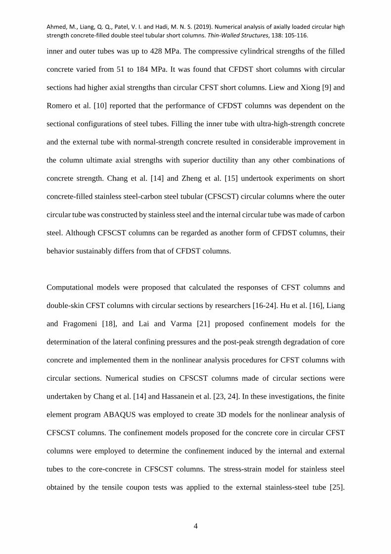
ABSTRACT
Circular high-strength concrete-filled double steel tubular (CFDST) columns are high
performance members where the internal and external steel tubes offer significant confinement
to the concrete infill. The confinement remarkably improves the concrete compressive strength
and ductility. However, no fiber element models have been formulated for computing the
responses of CFDST columns with circular steel tubes filled with high-strength concrete
incorporating accurate confinement to the core and sandwiched concrete. In this paper, a new
fiber-based numerical model is developed that computes the axial load-strain responses of
circular high-strength CFDST short columns under axial loading. Based on existing
experimental results, a new confining pressure model is developed for the determination of the
confining pressures on the core-concrete in CFDST columns with circular sections. A new
strength degradation parameter is also proposed that allows the concrete post-peak
characteristics to be quantified. The fiber-based numerical model validated by experimental
data is used to assess the responses of high-strength CFDST columns considering important
parameters, which include the inner steel tube, external tube diameter-to-thickness ratio and
*Corresponding author. Tel.: 61 3 9919 4134. E-mail address: [email protected] (Q. Q. Liang)

Ahmed, M., Liang, Q. Q., Patel, V. I. and Hadi, M. N. S. (2019). Numerical analysis of axially loaded circular high
strength concrete‐filled double steel tubular short columns. Thin‐Walled Structures, 138: 105‐116.
2
concrete and steel strengths. A simple expression is derived for the estimation of the axial load-
carrying capacities of circular short CFDST columns and comparisons with several design
codes are made. The proposed fiber-based analysis technique and design equation can
accurately determine the responses of short circular high-strength CFDST columns.
Keywords: Concrete-filled double steel tubes; composite columns; high-strength concrete;
numerical modeling.
1. Introduction
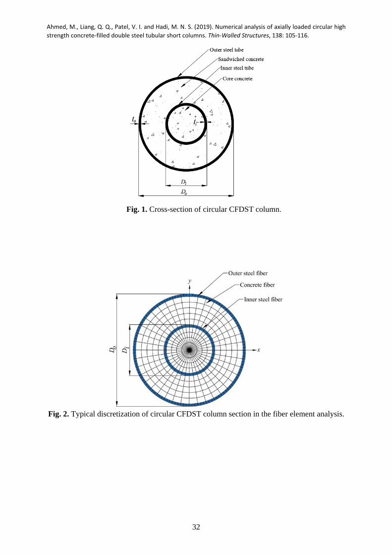
A circular concrete-filled double steel tubular (CFDST) column is fabricated by means of filling
concrete into two concentrically-placed circular hollow steel tubes as illustrated in Fig. 1. The
CFDST columns have higher ductility and strength performance than conventional circular
concrete-filled steel tubular (CFST) columns because the internal steel tube offers additional
confinement to the core-concrete. In addition, CFDST columns could be constructed by high-
strength concrete that allows further improvement in the column ultimate strengths, but its
brittleness affects the ductility of the columns. Analytical and experimental investigations on
circular high-strength CFDST columns constructed by carbon steel tubes have been very
limited. The confinement induced by the inner and external steel tubes to the core-concrete in
CFDST columns with circular sections has not been fully understood and quantified.
Furthermore, limited studies on CFDST columns have not resulted in the development of
appropriate design specifications in international standards for circular CFDST columns.
Therefore, it is important to propose an accurate numerical model that can accurately quantify
the confinement effects in circular CFDST columns to determine the behavior of CFDST
columns and propose design recommendation based on numerical solutions.

Ahmed, M., Liang, Q. Q., Patel, V. I. and Hadi, M. N. S. (2019). Numerical analysis of axially loaded circular high
strength concrete‐filled double steel tubular short columns. Thin‐Walled Structures, 138: 105‐116.
3
The performance of CFST columns made of circular and rectangular sections has been studied
by means of conducting experiments [1-6]. Portolés et al. [3] performed testes on slender
circular CFST columns exposed to eccentric loadings. It was observed from the tests that the
high-strength concrete increased the strength of shorter columns under small load eccentricities.
However, increasing the end eccentricity improved the column ductility. Their comparative
studies showed that the strengths of eccentrically-loaded slender CFST columns calculated by
the design approach given in Eurocode 4 [7] were conservative compared to test data. Similar
conclusions were given by O'Shea and Bridge [4] for circular CFST short columns under
combined actions. Xiong et al. [6] studied the experimental behavior of short CFST circular
columns constructed by means of using ultra-high-strength concrete (UHSC). They reported
that UHSC CFST short columns attained their ultimate axial strengths at small strains before
the core-concrete was confined by the steel tubes. In addition, the applied loads on the UHSC
CFST columns dropped sharply after the maximum load had been attained owing to the
brittleness of high-strength concrete.
In comparisons with experimental studies on CFST columns, only limited experimental
investigations on CFDST columns with circular sections were performed by researchers, such
as Xiong et al. [6], Peng et al. [8], Liew and Xiong [9], Romero et al. [10], Wan and Zha [11],
Ekmekyapar and Al-Eliwi [12]and Ibañez et al. [13]. Peng et al. [8] tested axially-loaded short
CFDST circular columns to failure. The cube strengths of the filled concrete in these specimens
varied from 66 MPa to 102 MPa. The diameter-to-thickness )/( oo tD ratios of the external tube
varied from 27 to 65.4 and the internal steel tube ii tD / ratios ranged from 14.1 to 22.8.
Experimental observations indicated that the column ultimate strengths were reduced by
increasing the /o oD t ratios of the outer tube. Xiong et al. [6] conducted experiments on circular
CFDST short columns where ultra-high-strength concrete was employed. The yield stress of
Ahmed, M., Liang, Q. Q., Patel, V. I. and Hadi, M. N. S. (2019). Numerical analysis of axially loaded circular high
strength concrete‐filled double steel tubular short columns. Thin‐Walled Structures, 138: 105‐116.
4
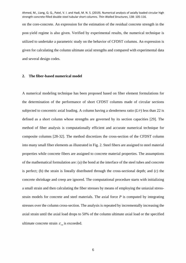
inner and outer tubes was up to 428 MPa. The compressive cylindrical strengths of the filled
concrete varied from 51 to 184 MPa. It was found that CFDST short columns with circular
sections had higher axial strengths than circular CFST short columns. Liew and Xiong [9] and
Romero et al. [10] reported that the performance of CFDST columns was dependent on the
sectional configurations of steel tubes. Filling the inner tube with ultra-high-strength concrete
and the external tube with normal-strength concrete resulted in considerable improvement in
the column ultimate axial strengths with superior ductility than any other combinations of
concrete strength. Chang et al. [14] and Zheng et al. [15] undertook experiments on short
concrete-filled stainless steel-carbon steel tubular (CFSCST) circular columns where the outer
circular tube was constructed by stainless steel and the internal circular tube was made of carbon
steel. Although CFSCST columns can be regarded as another form of CFDST columns, their
behavior sustainably differs from that of CFDST columns.
Computational models were proposed that calculated the responses of CFST columns and
double-skin CFST columns with circular sections by researchers [16-24]. Hu et al. [16], Liang
and Fragomeni [18], and Lai and Varma [21] proposed confinement models for the
determination of the lateral confining pressures and the post-peak strength degradation of core
concrete and implemented them in the nonlinear analysis procedures for CFST columns with
circular sections. Numerical studies on CFSCST columns made of circular sections were
undertaken by Chang et al. [14] and Hassanein et al. [23, 24]. In these investigations, the finite
element program ABAQUS was employed to create 3D models for the nonlinear analysis of
CFSCST columns. The confinement models proposed for the concrete core in circular CFST
columns were employed to determine the confinement induced by the internal and external
tubes to the core-concrete in CFSCST columns. The stress-strain model for stainless steel
obtained by the tensile coupon tests was applied to the external stainless-steel tube [25].

Ahmed, M., Liang, Q. Q., Patel, V. I. and Hadi, M. N. S. (2019). Numerical analysis of axially loaded circular high
strength concrete‐filled double steel tubular short columns. Thin‐Walled Structures, 138: 105‐116.
5
However, Quach et al. [26] reported that the compressive stress-strain responses of stainless
steels is greatly different from the tension behavior. The adoption of the constitutive model for
stainless steel based on the tensile coupon testes may lead to the underestimation of the ultimate
loads of CFSCST circular columns [19].
Numerical studies on circular CFDST short column constructed by carbon steel tubes have been
extremely scare [11, 27]. Wan and Zha [11] proposed a confining pressure model and a
softening reduction factor as a function of confining factors for determining the post-peak
responses of concrete in CFDST columns. However, it was found that the computed axial load-
strain curves deviated considerably from experimental data. This highlights that further studies
on the confinement mechanism are necessary and important in order to determine the actual
responses of CFDST columns constructed by circular sections. Ahmed et al. [28] formulated a
fiber-based mathematical model for short CFDST columns where the external tube was
rectangular and the internal tube was circular. The local buckling of rectangular steel tube and
concrete confinement were considered. The fiber analysis technique was demonstrated to
simulate well the responses of rectangular short CFDST columns.
The above literature review shows that no fiber-based mathematical models have been proposed
for the simulation of concentrically-loaded circular CFDST short columns constructed by
carbon steel tubes. To accurately determine the responses of short CFDST columns made of
circular sections, an accurate confinement model recognizing the effects of material properties
and geometry of CFDST circular sections needs to be developed. In this paper, a fiber-based
numerical method is formulated for the simulation of the axial behavior of CFDST columns
with circular sections filled with high-strength concrete incorporating concrete confinement. A
new formula is proposed based on experimental results for evaluating the confining pressures
Ahmed, M., Liang, Q. Q., Patel, V. I. and Hadi, M. N. S. (2019). Numerical analysis of axially loaded circular high
strength concrete‐filled double steel tubular short columns. Thin‐Walled Structures, 138: 105‐116.
6
on the core-concrete. An expression for the estimation of the residual concrete strength in the
post-yield regime is also given. Verified by experimental results, the numerical technique is
utilized to undertake a parametric study on the behavior of CFDST columns. An expression is
given for calculating the column ultimate axial strengths and compared with experimental data
and several design codes.
2. The fiber-based numerical model
A numerical modeling technique has been proposed based on fiber element formulations for
the determination of the performance of short CFDST columns made of circular sections
subjected to concentric axial loading. A column having a slenderness ratio (L/r) less than 22 is
defined as a short column whose strengths are governed by its section capacities [29]. The
method of fiber analysis is computationally efficient and accurate numerical technique for
composite columns [28-32]. The method discretizes the cross-section of the CFDST column
into many small fiber elements as illustrated in Fig. 2. Steel fibers are assigned to steel material
properties while concrete fibers are assigned to concrete material properties. The assumptions
of the mathematical formulation are: (a) the bond at the interface of the steel tubes and concrete
is perfect; (b) the strain is lineally distributed through the cross-sectional depth; and (c) the
concrete shrinkage and creep are ignored. The computational procedure starts with initializing
a small strain and then calculating the fiber stresses by means of employing the uniaxial stress-
strain models for concrete and steel materials. The axial force P is computed by integrating
stresses over the column cross-section. The analysis is repeated by incrementally increasing the
axial strain until the axial load drops to 50% of the column ultimate axial load or the specified
ultimate concrete strain cu is exceeded.

Ahmed, M., Liang, Q. Q., Patel, V. I. and Hadi, M. N. S. (2019). Numerical analysis of axially loaded circular high
strength concrete‐filled double steel tubular short columns. Thin‐Walled Structures, 138: 105‐116.
7
The ductility of a CFDST column in axial compression is expressed by the following indicator:
y
usdPI
(1)
in which u is the strain at the axial load that falls to 90% of the column ultimate strength in the
post-peak range or the ultimate strain in the post-yield ascending stress-strain branch. The yield
strain y is calculated as 0.75 / 0.75 , where 75.0 represents the strain under the axial load that
achieves 75% of the column ultimate axial load in the ascending branch [22, 33, 34]
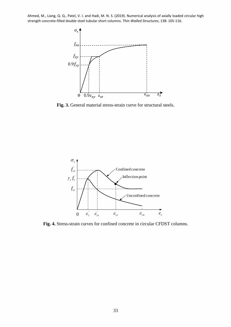
3. Material model for steel tubes
The internal and external steel tubes in a CFDST column with circular section are under biaxial
stresses resulting from the longitudinal compression and either hoop compression or tension
which lowers the yield stress of the steel tubes. To consider this effect, the yield stress is reduced
by a factor of 0.9 in the constitutive model for structural steels as shown in Fig. 3. The parabolic
curve in the strain range of 0.9 sy s st applied to cold-formed steels is defined using the
expression proposed by Liang [30] as
9.0
9.0 45
1
syst
syssys f
(2)
where s denotes the axial steel stress; s represents the axial steel strain; syf stands for the
steel yield strength; sy is the yield strain; and st is the strain at the onset of strain-hardening
Ahmed, M., Liang, Q. Q., Patel, V. I. and Hadi, M. N. S. (2019). Numerical analysis of axially loaded circular high
strength concrete‐filled double steel tubular short columns. Thin‐Walled Structures, 138: 105‐116.
8
and is taken as 0.005 in the present study.
The equations given by Mander [35] are utilized to calculate the stress from the axial strain
when the strain is in the range of susst , written as
)( sysu
n
stsu
ssusus fff
(3)
sysu
stsust ff
En (4)
in which suf denotes the steel tensile strength, 2.0su is the ultimate strain and stE represents
the steel modulus at the onset of strain-hardening and a value of sE02.0 is used.
4. Material model for confined concrete
4.1. General stress-strain curve
The two-stage stress-strain model presented in Fig. 4 is employed to model the responses of
confined concrete in CFDST columns with circular sections under axial compression. In the
first stage )0( 'ccc , the following formula by Mander et al. [36] is employed to calculate
the stress of the confined concrete from the axial strain:
1)/(
)/('
''
ccc
cccccc
f (5)
Ahmed, M., Liang, Q. Q., Patel, V. I. and Hadi, M. N. S. (2019). Numerical analysis of axially loaded circular high
strength concrete‐filled double steel tubular short columns. Thin‐Walled Structures, 138: 105‐116.
9
where c is the axial stress in compression and c denotes the corresponding strain; 'ccf and '
cc
represent the compressive strength and corresponding strain of the confined concrete,
respectively; and controls the initial slope and the curvature of the ascending branch and
given by
''
'
ccccc
ccc
fE
E
(6)
in which cE represents the concrete modulus of elasticity. Lim and Ozbakkaloglu [37] derived
an expression for estimating cE by analyzing many experimental results on concrete cylinders.
Their expression was modified by Ahmed et al. [28] to consider the effect of column size as
follows:
(MPa) '4400 ccc fE (7)
where c stands for the reduction factor applied to the concrete strength considering the
influence of the column size, proposed by Liang [30] for CFST columns as
)0.185.0(85.1 135.0 ccc D (8)
in which cD denotes the concrete-core diameter of circular CFST and CFDST columns, and
taken as )2( oo tD for sandwiched concrete and )2( ii tD for core-concrete in circular CFDST
columns.

Ahmed, M., Liang, Q. Q., Patel, V. I. and Hadi, M. N. S. (2019). Numerical analysis of axially loaded circular high
strength concrete‐filled double steel tubular short columns. Thin‐Walled Structures, 138: 105‐116.
10
In the second stage )( 'ccc , the descending stress-strain branch of confined-concrete is
defined by the equation formulated by Lim and Ozbakkaloglu [37] as
1
2
'
'
''
ccci
ccc
crccccc
fff
(9)
where crf represents the concrete residual strength and ci denotes the concrete strain
corresponding to the inflection point, which defines the shape of the stress-strain curve in the
post-peak range as illustrated in Fig. 4.
Parameters studies show that the '/cr ccf f ratio is mainly influenced by the /D t ratio and 'cf .
Based on the regression analyses, an expression is proposed for '/cr ccf f as follows:
)010(004400029024201 .f
f f .
t
D . .
f
f'
cc
cr'cc'
cc
cr
(10)
The accuracy of the proposed Eq. (10) for calculating the normalized residual strength of
concrete ( '/cr ccf f ) is examined in Fig. 5 against the results obtained from the parametric study
on 92 test data [1, 2, 6, 8, 9, 11, 12, 38, 39].
Lim and Ozbakkaloglu [37] provided a formula for determining the strain ( ci ) at the inflection
point based on extensive test results. Their formula was modified by Ahmed et al. [28] by using
c to incorporate the column size effect as follows:

Ahmed, M., Liang, Q. Q., Patel, V. I. and Hadi, M. N. S. (2019). Numerical analysis of axially loaded circular high
strength concrete‐filled double steel tubular short columns. Thin‐Walled Structures, 138: 105‐116.
11
0.12 0.47' ' ' '' '
2.8 10 1cr crci cc c c cc c c
cc cc
f ff f
f f
(11)
The concrete ultimate strain )( cu as illustrated in Fig. 4 is specified and used as the stopping
criterion in the numerical analysis.
4.2. Compressive strength and strain of confined concrete
As illustrated in Fig. 4, when the axial compressive concrete stress exceeds the effective
strength 'c cf of concrete in a CFDST column with circular section, the concrete is said to be
confined by the steel tubes. This implies that the confined-concrete compressive strength
increases from 'c cf to the maximum value '
ccf with increasing the axial load [22]. The
maximum strength ( 'ccf ) and its corresponding strain ( '
cc ) of the concrete confined are
determined by the formulas provided by Mander et al. [36] incorporating the factor c given by
Liang and Fragomeni [18] as follows:
1' ''
1 rpcc c c
c c
k ff f
f
(12)
'
'2''
cc
crpccc f
fk
(13)
in which rpf represents the confining pressure on the concrete offered by the tubes. In the
present study, 1 4.1k and 2 20.5k provided by Richart et al. [40] are used. The axial strain
Ahmed, M., Liang, Q. Q., Patel, V. I. and Hadi, M. N. S. (2019). Numerical analysis of axially loaded circular high
strength concrete‐filled double steel tubular short columns. Thin‐Walled Structures, 138: 105‐116.
12
'c at '
cf depends on the effective concrete strength in compression. The following equation
given by De Nicolo et al. [41] for computing the strain 'c is adopted in the present study:
' ' 70.00076 (0.626 4.33) 10c c cf (14)
4.3. Confining pressure model for sandwiched concrete
Experimental results showed that the outer tube of a circular CFDST column was forced to
buckle locally outward and the sandwiched concrete crushed where the steel tube buckled [6,
11, 12]. The finite element analyses on circular CFST and CFDST columns conducted by Chang
et al. [21] indicated that the longitudinal compressive stress in the core-concrete in the circular
CFDST column was higher than that in the corresponding concrete in the CFST column.
However, the longitudinal compressive stress in the sandwiched concrete in the CFDST column
was similar to that in the corresponding concrete in the CFST column. This implies that in a
CFDST short column under axial compression, the core-concrete is confined by both the outer
and inner steel tubes but the sandwiched-concrete is confined mainly by the outer steel tube and
the confinement provided by the inner steel tube on the sandwiched concrete is insignificant
and can be ignored. In this study, the lateral pressure on the sandwiched concrete ( )rpof in
CFDST columns made of circular sections is estimated by the following expressions provided
by Hu et al. [16]:
0.043646 0.000832 for 21.7 47
0.006241 0.0000357 for 47< 150
o o
o orpo
syo o o
o o
D D
t tf
f D D
t t
(15)

Ahmed, M., Liang, Q. Q., Patel, V. I. and Hadi, M. N. S. (2019). Numerical analysis of axially loaded circular high
strength concrete‐filled double steel tubular short columns. Thin‐Walled Structures, 138: 105‐116.
13
4.4. Proposed confining pressure model for core concrete
The confining pressure model for the core concrete was developed by means of interpreting the
experimental data of 34 circular short CFDST columns given in Table 1 [6, 8-9,11-12]. The
maximum axial load on the axial load-strain curve with softening was used as the ultimate axial
strength of the CFDST column. For specimens without softening behavior, the axial load at the
ultimate strain was assumed to reach its ultimate state. The compressive strength for the
confined core-concrete was calculated by subtracting the capacities of the sandwiched concrete
and internal and external steel tubes. The lateral pressure ( ,exprpif ) on the core concrete obtained
from experiments was then determined using Eq. (16). By undertaking the regression analyses
on the experimental data given in Table 1, a new expression for quantifying the confining
pressure exerted on the core-concrete in CFDST columns with circular sections is proposed as
12.2897 0.0066 0.1918 0.0585 0.3801 0o i o irpi rpi
o i o i
D D D Df f
t t t t
(16)
in which Di and oD are the diameters of the internal and external steel tubes, respectively; it
and 0t are the thickness of the inner and outer tubes, respectively; and is the confinement
factor which is expressed by
''
,,
cccccsccsc
isysiosyso
fAfA
fAfA
(17)
in which soA , siA , scA and ccA are the cross-sectional areas of the outer tube, inner tube,
sandwiched-concrete and core-concrete, respectively; 'ccf and '
scf are the strengths of the core

Ahmed, M., Liang, Q. Q., Patel, V. I. and Hadi, M. N. S. (2019). Numerical analysis of axially loaded circular high
strength concrete‐filled double steel tubular short columns. Thin‐Walled Structures, 138: 105‐116.
14
concrete and sandwiched concrete in compression, respectively; syif and syof are the yield
stresses of the internal and external tubes, respectively. Figure 6 shows that the lateral pressures
calculated by the proposed Eq. (16) are in good correlation with test data.
5. Comparisons of computer solutions with test results
The accuracy of the fiber-based numerical model incorporating the proposed confining pressure
model and material constitutive laws is established by means of comparing computations with
corresponding measurements provided by Xiong et al. [6], Peng et al. [8], Liew and Xiong [9],
Wan and Zha [11] and Ekmekyapar and Al-Eliwi [12]. Table 1 gives the material and geometric
properties of 40 tested CFDST short columns. The unconfined concrete strengths were
determined by the compression tests on concrete cubes )( 'cuf , concrete cylinders of 100×200
mm )( '100,cf or concrete cylinders of 150×300 mm )( '
cf . For consistency, the unconfined
concrete strengths were converted to 'cf using the conversion of 05.1/'
100,ckf and '85.0 cuf ,
respectively.
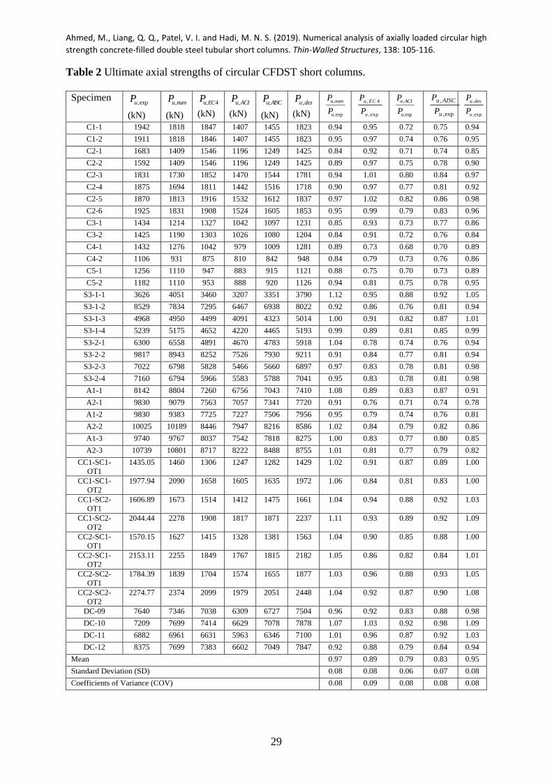
The predicted ultimate axial loads )( ,numuP by the numerical model and the experimental values
)( exp,uP are given in Table 2. It is observed that the fiber modeling technique accurately
determines the capacities of short CFDST circular columns. The statistical study indicates that
the mean exp,, / unumu PP ratio is calculated as 0.97 while both the coefficient of variation and
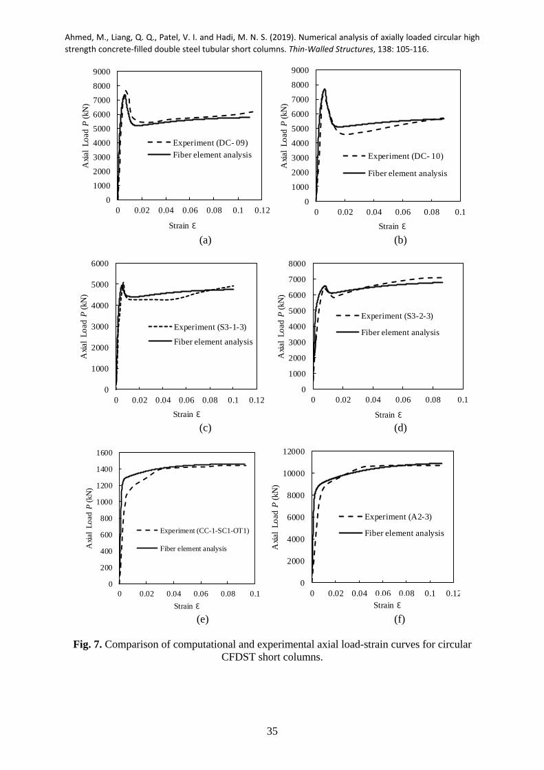
standard deviation are 0.08. The simulated axial load-strain behavior of high-strength CFDST
columns are provided in Fig. 7. The measured axial load-strain performance of the tested
columns is determined by the mathematical model with reasonable accuracy. The
experimentally measured column initial axial stiffness slightly differs from the predicted one.

Ahmed, M., Liang, Q. Q., Patel, V. I. and Hadi, M. N. S. (2019). Numerical analysis of axially loaded circular high
strength concrete‐filled double steel tubular short columns. Thin‐Walled Structures, 138: 105‐116.
15
The fiber-based modeling method also gives a good simulation of the post-yield responses of
the CFDST columns. The discrepancy between the predictions and measurements is caused by
the uncertainty of the actual concrete strength and stiffness in the tested specimens and the
average concrete strength was used in the numerical analyses.
6. Parametric study
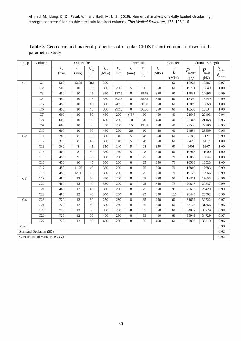
The mathematical model proposed was utilized to examine the structural behavior of short
circular high-strength CFDST columns. The details on the CFDST columns under
investigations are provided in Table 3. Steel tubes having the yield stresses of 250, 300, 350,
400 and 450 MPa were used in the numerical analyses and their corresponding tensile strengths
were 320, 400, 420, 500 and 520 MPa, respectively. In the parametric study, the ultimate
concrete strain cu was taken as 0.04 which gives conservative results of columns with
ascending stress-strain behavior in the post-yield range.
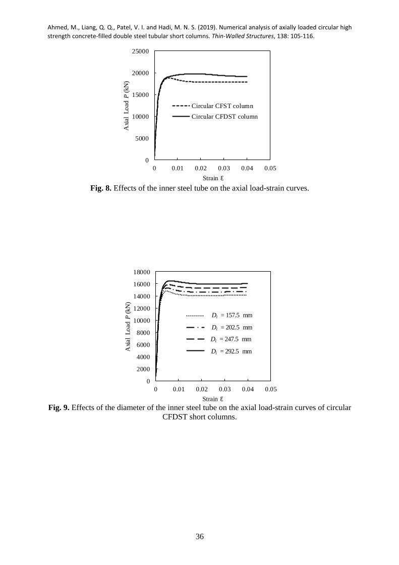
6.1. Influences of the internal steel tube
The effects of the internal tube on the strength as well as ductility of the CFDST column were
examined by comparing its axial load-strain response with that of the conventional CFST
column. For this purpose, analyses on Columns C1 and C2 presented in Group G1 in Table 3
were undertaken by the mathematical model. Both columns had the same outer tube diameter
as well as the steel area and were made of high-strength concrete of 60 MPa. Figure 8 shows
that the CFDST column has 4.85% higher strength than the CFST column due to the inclusion
of the internal circular tube. The reason for the strength increase is that the inner steel tube
provides additional confinement to the core-concrete, which increases the strength of the core-

Ahmed, M., Liang, Q. Q., Patel, V. I. and Hadi, M. N. S. (2019). Numerical analysis of axially loaded circular high
strength concrete‐filled double steel tubular short columns. Thin‐Walled Structures, 138: 105‐116.
16
concrete thereby the column ultimate strength. The CFDST column also has a better ductility
than the CFST column. However, the column initial stiffness is not affected by the internal tube.
The influences of the internal tube diameter on the column behavior were evaluated by
analyzing Columns C3-C6 in Group G1 in Table 3. Only the inner tube diameter ( iD ) was
varied in this investigation. Figure 9 presents the calculated axial loads as a function of axial
strains for these CFDST columns. The ultimate axial loads of short circular CFDST columns
are found to increase significantly as iD increases. By increasing the diameter iD from 157.5
mm to 202.5, 247.5 and 292.5 mm, the percentage increases in the column ultimate strengths
are 3.4%, 7.1% and 11.4%, respectively. It would appear that increasing the diameter iD reduces
the sandwiched-concrete area but increases the core-concrete area. This implies that more
concrete would be confined by the internal tube. Consequently, the strength of the CFDST
column increases. Figure 9 indicates that the column initial axial stiffness is slightly affected
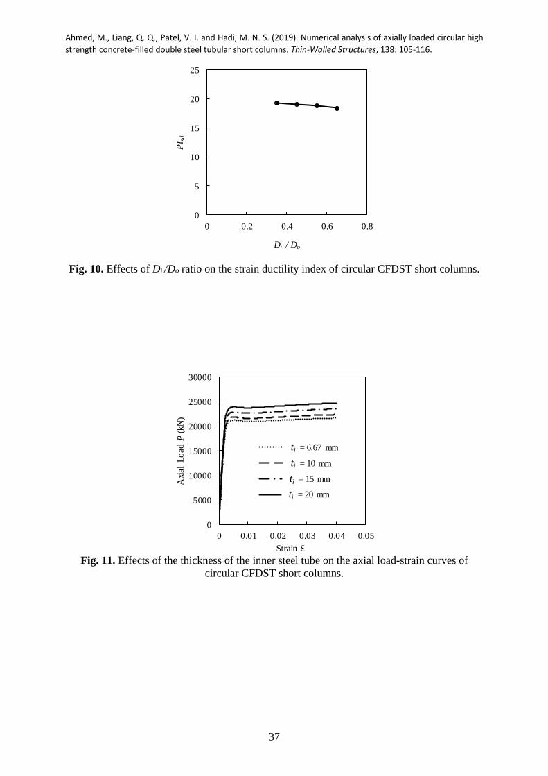
by the inner tube diameter. The computed ductility indices of CFDST columns having different
diameters are provided in Fig. 10. It would appear that circular CFDST short columns have
very good ductility with a strain ductility index greater than 16.0. It is discovered that the
ductility index of CFDST columns has a slight decrease as the inner steel tube diameter reduces.
Investigations were undertaken on the influences of the internal tube thickness on the behavior
of CFDST columns. Columns C7-C10 in Group G1 in Table 3 with thickness ranged from 6.67
to 20 mm were analyzed. The results computed by the numerical technique are shown in Fig.
11. It appears that the ultimate axial strength of CFDST column increases considerably with
increasing the thickness of the internal tube. The increase in the column ultimate strength is
14.1% when the thickness it is increased from 6.67 mm to 20 mm. This can be explained by
the fact that increasing the inner tube thickness leads to an increase in the steel area with yield

Ahmed, M., Liang, Q. Q., Patel, V. I. and Hadi, M. N. S. (2019). Numerical analysis of axially loaded circular high
strength concrete‐filled double steel tubular short columns. Thin‐Walled Structures, 138: 105‐116.
17
stress of 450 MPa but the same reduction in the core-concrete area with compressive strength
of 40 MPa, which results in a considerable increase in the ultimate axial strength of the column.
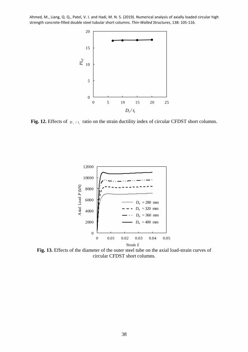
As demonstrated in Fig. 12, reducing the thickness it causes a slight decrease in the ductility
because of the reduction in the internal tube area. The numerical results presented in Fig. 12
indicate that when the thickness it is reduced from 20 mm to 15, 10 and 6.67 mm, the axial
ductility index decreases from 17.40 to 17.35, 17.31 and 17.20, respectively.
It has been demonstrated that circular CFDST columns possess higher strength and ductility
than circular CFST columns. High strength inner steel tubes may be used to further increase the
column capacity. The use of the inner steel tube instead of reinforcing bars certainly speeds up
the construction process. Moreover, the existing conventional CFST column can be
strengthened by using an additional external steel tube filled with concrete and it becomes a
CFDST column. However, to achieve economical and efficient designs, the cross-sections of
CFDST columns must be properly designed. The proposed computational model can be used
to analyze the cross-sectional capacities of CFDST columns to determine the optimal designs
of CFDST columns.
6.2. Influences of /o oD t ratio
The behavior of CFDST columns is significantly dependent on the /o oD t ratios. Two scenarios
were considered to examine the effects of /o oD t ratios. The CFDST columns with /o oD t ratios
of 35, 40, 45 and 50 given in Group G2 in Table 3 were examined in the first scenario by
changing the outer tube diameter oD only. Figure 13 gives the computed load-strain
relationships of these columns. It would appear that increasing the external steel tube diameter
Ahmed, M., Liang, Q. Q., Patel, V. I. and Hadi, M. N. S. (2019). Numerical analysis of axially loaded circular high
strength concrete‐filled double steel tubular short columns. Thin‐Walled Structures, 138: 105‐116.
18
oD significantly increases the column axial strength. By increasing oD from 280 mm to 320,
360 and 400 mm, the increases in the column axial strengths are 17.4%, 33.7% and 52.8%,
respectively. This is because increasing the diameter of the outer tube increases the areas of
both steel tube and concrete so that the column ultimate axial load increases. As depicted in
Fig. 13, the column initial stiffness increases considerably with an increase in the /o oD t ratio,
however, it has an insignificant impact on the post-peak responses of CFDST columns. The
axial strain ductility indices are given in Fig. 14. The ductility indices are found to vary with
/o oD t ratios. The computed axial ductility indexes are 16.3, 17.32, 18.73 and 19.63 for columns
with /o oD t ratios of 35, 40, 45 and 50, respectively.
In the second scenario, only the external tube thickness ot was changed to determine the /o oD t
ratios as 35, 40, 45 and 50 as shown in Group G2 in Table 3. The axial load-strain curves
predicted are given in Fig. 15. It would appear that decreasing the thickness ot significantly
decreases the column ultimate strength. The strength reductions are computed as 6.7%, 13.4%
and 17.3%, respectively when the thickness ot is reduced from 12.86 mm to 11.25, 10 and 9
mm, respectively. The reason for this is that deceasing the outer tube thickness reduces the steel
tube area and the confinement on the sandwiched and core concrete so that the column axial
loads decease significantly. It can be seen from Fig. 15 that the /o oD t ratio influences the post-
yield curves. Figure 16 illustrates that increasing the /o oD t ratio improves the axial ductility.
For CFDST short columns with /o oD t ratio of 35, 40, 45 and 50, the calculated strain ductility
indexes are 16.05, 17.08, 18.44 and 19.06, respectively.
6.3. Influences of concrete compressive strength

Ahmed, M., Liang, Q. Q., Patel, V. I. and Hadi, M. N. S. (2019). Numerical analysis of axially loaded circular high
strength concrete‐filled double steel tubular short columns. Thin‐Walled Structures, 138: 105‐116.
19
In Group G3 in Table 3, the concrete of different strengths was used to construct CFDST
columns. The compressive concrete strengths of 55 MPa, 75 MPa, 95 MPa and 115 MPa were
considered in the fiber analysis. The predicted load-strain responses presented in Fig. 17
indicate that using higher strength concrete significantly improves the ultimate strength of
CFDST columns. When 'cf increases from 55 MPa to 75 MPa, 95 MPa and 115 MPa, the
increases in the column ultimate strengths are 13.7%, 29.2% and 44.4%, respectively. This can
be explained by the fact that the ultimate axial load of short CFDST columns is governed by its
section and material properties such as the concrete compressive strength. However, it is
noticed that CFDST columns constructed using high-strength concrete are less ductile due to
its brittle behavior.
6.4. Influences of steel yield strength
The yield stress of steel tubes has influences on the behavior of CFDST columns and its effect
was studied by using the fiber-based model. The Columns in Group G4 in Table 3 were
considered for this study. The calculated responses of these CFDST columns constructed by
steel tubes having various yield stresses are given Fig.18. It is observed that the ultimate
strength of the CFDST column significantly increases when the steel yield stress is increased.
When the yield stress is increased from 250 MPa to 300 MPa, 350 MPa, 400 MPa and 450
MPa, the column ultimate strength is found to increase by 4.7%, 7.5%, 13.4% and 19.4%,
respectively. The reason for the column strength increase is that the ultimate axial strength of a
short CFDST column is governed by its section and material properties such as the steel yield
strength. The strain ductility indices of CFDST columns are depicted in Fig. 19. It is shown that
the ductility index of the column increases with an increase in its steel yield strength up to 350
MPa and after that it decreases as its steel yield strength increases.

Ahmed, M., Liang, Q. Q., Patel, V. I. and Hadi, M. N. S. (2019). Numerical analysis of axially loaded circular high
strength concrete‐filled double steel tubular short columns. Thin‐Walled Structures, 138: 105‐116.
20
7. Proposed design model
Currently, there are no design specifications available for the design of stub CFDST columns
constructed by circular carbon steel tubes. Previously, Liang and Fragomeni [18] proposed a
formula for the computation of the ultimate axial capacities of CFST columns with circular
cross-sections under axial loading considering confinement effects. Liang [22] also derived
design formulas for double-skin CFST short columns in axial compression. Hassanein et al.
[23] recommended a formula for the design of CFSCST columns where the outer tube was
made of duplex stainless steel. Based on the proposed model for lateral pressures on core-
concrete and the previously cited work [18, 22], a new simple expression for the estimation of
the ultimate strength of short circular CFDST columns is proposed as
ccrpicccscrpocscsisyisisosyosodesignu AffAffAfAfP )1.4()1.4( '', (18)
where so and si are strength factors, accounting for the influences of hoop-tension, strain
hardening as well as imperfections on the outer tube and inner tube, respectively and were
developed by Liang and Fragomeni [18] as
1.19.0 458.11.0
soo
oso t
D (19)
1.19.0 458.11.0
sii
isi t
D (20)
The proposed design equation is verified by comparing calculations with test data of 40 CFDST
columns in Table 2, where ,u desP , ,expuP and ,u numP are the ultimate axial loads calculated using
Ahmed, M., Liang, Q. Q., Patel, V. I. and Hadi, M. N. S. (2019). Numerical analysis of axially loaded circular high
strength concrete‐filled double steel tubular short columns. Thin‐Walled Structures, 138: 105‐116.
21
Eq. (18), obtained from experiments and determined by the fiber analysis, respectively. It is
observed that the mean ,u desP / ,expuP ratio is 0.97 and the calculated coefficient of variance and
standard deviation are 0.08. The strength computations of circular CFDST columns by the
design model are further validated by numerical predictions in Table 3. It is shown that the
strengths computed by the design model agree extremely well with corresponding numerical
predictions. The proposed design formula can predict 98% of the numerical strengths with a
coefficient of variance of 0.02.
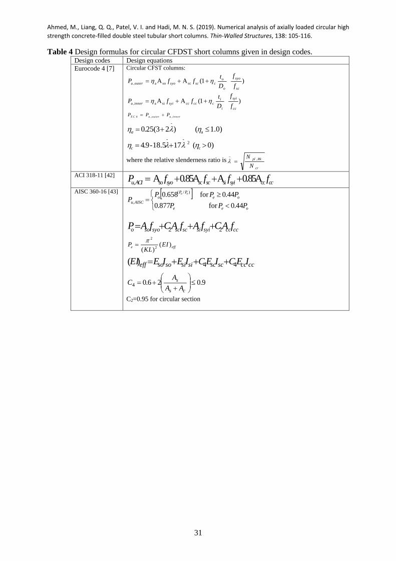
8. Comparisons with design codes
The applicability of the existing design specifications for short circular CFST columns given in
Eurocode 4 [7], ACI 318-11 [42] and AISC 360-16 [43] to circular CFDST columns is
examined herein. Table 4 presents the specifications of the design codes to calculate the
ultimate axial strengths. Eurocode 4 accounts for the influence of concrete confinement on the
strength calculations of CFST circular columns whereas ACI 318-11 and AISC 360-16 neglect
this effect. Table 2 summaries the comparisons between design calculations and measured
results on 40 tested CFDST short columns. The calculated ultimate strengths using ACI 318-
11and AISC 360-16 codes are very conservative compared to test results. Although the design
method specified in Eurocode 4 yields better estimations of the load-carrying capacities of
CFDST columns than ACI 318-11 and AISC 360-16, but it could not capture the actual
improvement in the core concrete strength. The mean calculated-to-measured ultimate axial
strengths calculated by suing Eurocode 4, ACI 318-11and AISC 360-16 are 0.89, 0.79 and 0.83,
respectively. On the contrary, the proposed design model generally yields better strength
predictions of short CFDST columns than design codes. The current design equation given in
Eurocode 4 [7] for CFST columns is simpler than the proposed Eq. (18), but Eq. (18) yields

Ahmed, M., Liang, Q. Q., Patel, V. I. and Hadi, M. N. S. (2019). Numerical analysis of axially loaded circular high
strength concrete‐filled double steel tubular short columns. Thin‐Walled Structures, 138: 105‐116.
22
more accurate results than the current design provision. Further studies should focus on
developing a more simple revision to the current design provision in Eurocode 4 for the design
of CFDST columns.
9. Conclusions
This paper has described a fiber-based mathematical model formulated for the numerical
simulations of short circular CFDST columns subjected to axial loading. A new model for
computing the confining pressures on the core-concrete has been proposed based on existing
test data together with a new strength-degradation parameter for quantifying the post-peak
responses of confined concrete. The accuracy of the developed numerical analysis technique
incorporating the new proposals of material constitutive laws has been examined by
comparisons with experimental results of CFDST columns. Details parametric studies have
been conducted considering various columns geometry and material properties. A new design
formula has been derived and verified by test results. Furthermore, the applicability of the
existing design rules recommended by Eurocode 4 [7], ACI 318-11 [42] and AISC 360-16 [43]
for circular CFST columns to circular CFDST columns has been investigated.
The conclusions are given as follows:
(1) The fiber-based mathematical model developed produces predictions which are in good
correlations with experimental data of circular CFDST columns under axial compression.
(2) If both circular CFDST and CFST columns have the same external tube diameter and the
same steel area, the CFDST column has higher strength and ductility than the CFST
column.

Ahmed, M., Liang, Q. Q., Patel, V. I. and Hadi, M. N. S. (2019). Numerical analysis of axially loaded circular high
strength concrete‐filled double steel tubular short columns. Thin‐Walled Structures, 138: 105‐116.
23
(3) Increasing the inner steel-tube diameter remarkably improves the ultimate strength of the
CFDST column.
(4) Increasing the thickness of the inner tube considerably increases the ultimate axial loads of
CFDST columns made of normal strength concrete but its effect diminishes when high-
strength concrete is used.
(5) The use of higher strength steel tubes and concrete results in higher axial capacities, but it
considerably affects the column axial ductility.
(6) The design rules specified in Eurocode 4 [7], ACI 318-11[42] and AISC 360-16 [43] for
circular CFST columns give conservative calculations of the ultimate axial strengths of
short CFDST columns made of circular steel sections.
(7) The design formula proposed yields more accurate ultimate strength predictions of CFDST
columns than the design approaches provided in existing design codes.
References
[1] K. Sakino, H. Nakahara, S. Morino, I. Nishiyama, Behavior of centrally loaded concrete-
filled steel-tube short columns, J. Struct. Eng. ASCE 130 (2) (2004) 180-188.
[2] G. Giakoumelis, D. Lam, Axial capacity of circular concrete-filled tube columns, J.
Constr. Steel Res. 60 (7) (2004) 1049-1068.
[3] J.M. Portolés, M.L. Romero, J.L. Bonet, F.C. Filippou, Experimental study of high
strength concrete-filled circular tubular columns under eccentric loading, J. Constr. Steel
Res. 67 (4) (2011) 623-633.
[4] M.D. O'Shea, R.Q. Bridge, Design of circular thin-walled concrete filled steel tubes, J.
Struct. Eng. ASCE 126 (11) (2000) 1295-1303.
Ahmed, M., Liang, Q. Q., Patel, V. I. and Hadi, M. N. S. (2019). Numerical analysis of axially loaded circular high
strength concrete‐filled double steel tubular short columns. Thin‐Walled Structures, 138: 105‐116.
24
[5] J.Y.R. Liew, M.X. Xiong, D.X. Xiong, Design of concrete filled tubular beam-columns
with high strength steel and concrete, Structures 8 (2016) 213-226.
[6] M.X. Xiong, D.X. Xiong, J.Y.R. Liew, Axial performance of short concrete filled steel
tubes with high-and ultra-high-strength materials, Eng .Struct. 136 (2017) 494-510.
[7] Eurocode 4, Design of Composite Steel and Concrete Structures-Part 1-1: General Rules
and Rules for Buildings, European Committee for Standardization, CEN, Brussels,
Belgium, 2004.
[8] Y.Y. Peng, K.F. Tan, Y. Yao, Mechanical properties of duplex steel tube high- strength
concrete short columns under axial compression, J. Wuhan Uni. of Tech. 33 (2) (2011)
105-109 (In Chinese).
[9] J.Y.R. Liew, D.X. Xiong, Ultra-high strength concrete filled composite columns for
multi-storey building construction, Adv. in Struct. Eng. 15 (9) (2012) 1487-1503.
[10] M.L. Romero, A. Espinós, J. Portolés, A. Hospitaler, C. Ibañez, Slender double-tube
ultra-high strength concrete-filled tubular columns under ambient temperature and fire,
Eng. Struct. 99 (2015) 536-545.
[11] C.Y. Wan, X.X. Zha, Nonlinear analysis and design of concrete-filled dual steel tubular
columns under axial loading, Steel Comp. Struct. 20 (3) (2016) 571-597.
[12] T. Ekmekyapar, B.J. Al-Eliwi, Concrete filled double circular steel tube (CFDCST) stub
columns, Eng. Struct. 135 (2017) 68-80.
[13] C. Ibañez, M.L. Romero, A. Espinos, J. Portolés, V. Albero, Ultra-high strength concrete
on eccentrically loaded slender circular concrete-filled dual steel columns, Structures 12
(2017) 64-74.
[14] X. Chang, Z.L. Ru, W. Zhou, Y.B. Zhang, Study on concrete-filled stainless steel–carbon
steel tubular (CFSCT) stub columns under compression, Thin-Walled Struct. 63 (2013)
125-133.
Ahmed, M., Liang, Q. Q., Patel, V. I. and Hadi, M. N. S. (2019). Numerical analysis of axially loaded circular high
strength concrete‐filled double steel tubular short columns. Thin‐Walled Structures, 138: 105‐116.
25
[15] Y. Zheng, C. He, L. Zheng, Experimental and numerical investigation of circular double-
tube concrete-filled stainless steel tubular columns under cyclic loading, Thin-Walled
Struct. 132 (2018) 151-166.
[16] H.T. Hu, C.S. Huang, M.H. Wu, Y.M. Wu, Nonlinear analysis of axially loaded concrete-
filled tube columns with confinement effect, J. Struct. Eng. ASCE 129 (10) (2003) 1322-
1329.
[17] E. Ellobody, B. Young, D. Lam, Behaviour of normal and high strength concrete-filled
compact steel tube circular stub columns, J. Constr. Steel Res. 62 (7) (2006) 706-715.
[18] Q.Q. Liang, S. Fragomeni, Nonlinear analysis of circular concrete-filled steel tubular
short columns under axial loading, J. Constr. Steel Res. 65(12) (2009) 2186-2196.
[19] V.I. Patel, Q.Q. Liang, M.N.S. Hadi, Nonlinear analysis of axially loaded circular
concrete-filled stainless steel tubular short columns, J. Constr. Steel Res. 101 (2014) 9-
18.
[20] F.C. Wang, L.H. Han, W. Li, Analytical behavior of CFDST stub columns with external
stainless steel tubes under axial compression, Thin-Walled Struct. 127 (2018) 756-768.
[21] Z. Lai, A.H. Varma, Effective stress-strain relationships for analysis of noncompact and
slender filled composite (CFT) members, Eng. Struct. 124 (2016) 457-472.
[22] Q.Q. Liang, Nonlinear analysis of circular double-skin concrete-filled steel tubular
columns under axial compression, Eng. Struct. 131 (2017) 639-650.
[23] M.F. Hassanein, O.F. Kharoob, Q.Q. Liang, Behaviour of circular concrete-filled lean
duplex stainless steel–carbon steel tubular short columns, Eng. Struct. 56 (2013) 83-94.
[24] M.F. Hassanein, M. Elchalakani, V.I. Patel, Overall buckling behaviour of circular
concrete-filled dual steel tubular columns with stainless steel external tubes, Thin-Walled
Struct. 115 (2017) 336-348.
Ahmed, M., Liang, Q. Q., Patel, V. I. and Hadi, M. N. S. (2019). Numerical analysis of axially loaded circular high
strength concrete‐filled double steel tubular short columns. Thin‐Walled Structures, 138: 105‐116.
26
[25] K.J. Rasmussen, Full-range stress–strain curves for stainless steel alloys, J. Constr. Steel
Res. 59 (1) (2003) 47-61.
[26] W. Quach, J.G. Teng, K. Chung, Three-stage full-range stress-strain model for stainless
steels, J. Struct. Eng. ASCE 134 (9) (2008) 1518-1527.
[27] D. Pons, A. Espinos, V. Albero, M.L Romero, Numerical study on axially loaded ultra-
high strength concrete-filled dual steel columns, Steel and Comp. Struct. 26 (6) (2018)
705-717.
[28] M. Ahmed, Q.Q. Liang, V.I. Patel, M.N.S. Hadi, Nonlinear analysis of rectangular
concrete-filled double steel tubular short columns incorporating local buckling, Eng.
Struct. 175 (2018)13-26.
[29] Q.Q. Liang, Analysis and Design of Steel and Composite Structures, CRC Press, Taylor
and Francis Group, Boca Raton and London, 2014.
[30] Q.Q. Liang, Performance-based analysis of concrete-filled steel tubular beam–columns,
Part I: Theory and algorithms, J. Constr. Steel Res. 65 (2) (2009) 363-372.
[31] Q.Q. Liang, Performance-based analysis of concrete-filled steel tubular beam–columns,
Part II: Verification and applications, J. Const. Steel Res. 65 (2) (2009) 351-362.
[32] V.I. Patel, Q.Q. Liang, M.N.S. Hadi, Concrete-filled stainless steel tubular columns, CRC
Press, Taylor and Francis Group, Boca Raton and London, 2018.
[33] R. Park, Evaluation of ductility of structures and structural subassemblages from
laboratory testing, Bull. New Zealand Soc. Earthq. Eng. 22(3) (1989) 155–166.
[34] Z. Tao, L.H. Han, Z.L. Zhao, Behavior of concrete-filled double skin (CHS inner and
CHS outer) steel tubular stub columns and beam-columns, J. Constr. Steel Res. 60 (2004)
1129–1158.
[35] J.B. Mander, Seismic design of bridge piers, Ph.D. Thesis, Depart. of Civil Eng. Uni. of
Canterbury, Christchurch, New Zealand, 1983.
Ahmed, M., Liang, Q. Q., Patel, V. I. and Hadi, M. N. S. (2019). Numerical analysis of axially loaded circular high
strength concrete‐filled double steel tubular short columns. Thin‐Walled Structures, 138: 105‐116.
27
[36] J.B. Mander, M.J. Priestley, R. Park, Theoretical stress-strain model for confined
concrete, J. Struct. Eng. ASCE 114 (8) (1988) 1804-1826.
[37] J.C. Lim, T. Ozbakkaloglu, Stress–strain model for normal-and light-weight concretes
under uniaxial and triaxial compression, Constr. Build. Mater. 2014; 71 (2014) 492-509.
[38] S.P. Schneider, Axially loaded concrete-filled steel tubes, J. Struct. Eng. 124 (10) (1998)
1125-1138.
[39] L.H. Han, G.H. Yao GH, X.L. Zhao, Tests and calculations for hollow structural steel
(HSS) stub columns filled with self-consolidating concrete (SCC), J. Constr. Steel Res.
61 (9) (2005) 1241-1269.
[40] F.E. Richart, A. Brandtzaeg, R.L. Brown, A study of the failure of concrete under
combined compressive stresses, Uni. of Illinois at Urbana Champaign, College of Eng.
Eng. Exp. Station, 1928.
[41] B. De Nicolo, L. Pani, E. Pozzo, Strain of concrete at peak compressive stress for a wide
range of compressive strengths, Mater. and Struct. 27 (4) (1994) 206-210.
[42] ACI 318-11, Building Code Requirements for Reinforced Concrete, American Concrete
Intitute, Detroit (MI), 2011.
[43] AISC 360-16, Specification for Structural Steel Buildings, American Institute of Steel
Construction, Chicago (IL), 2016.

Ahmed, M., Liang, Q. Q., Patel, V. I. and Hadi, M. N. S. (2019). Numerical analysis of axially loaded circular high
strength concrete‐filled double steel tubular short columns. Thin‐Walled Structures, 138: 105‐116.
28
Figures and tables
Table 1 Geometric and material properties of tested circular CFDST short columns.
Specimen
Outer Tube Inner Tube Concrete Ref. o oD t
(mm) o
o
D
t,sy of
(MPa)
,su of
(MPa) ,s oE
(GPa)
i iD t
(mm) i
i
D
t,sy if
(MPa)
,su if
(MPa) ,s iE
(GPa)
',c of
(MPa)
',c if
(MPa)
C1-1 133× 4.5 29.6 361 410 200 55.9×3.4 16.4 361 410 200 56.1 56.1 [8] C1-2 133×4.5 29.6 361 410 200 56×3.4 16.6 361 410 200 56.1 56.1
C2-1 132.5×3.0 44.2 361 410 200 56×3.0 18.7 361 410 200 56.1 56.1
C2-2 132.5×3.0 44.2 361 410 200 56×3.0 18.7 361 410 200 56.1 56.1
C2-3 132.3×3.2 41.3 361 410 200 56.1×3.2 17.5 361 410 200 79.9 79.9
C2-4 132×3.0 44.0 361 410 200 56.1×3.2 17.5 361 410 200 79.9 79.9
C2-5 132.1×3.1 42.6 361 410 200 56×3.4 16.5 361 410 200 86.7 86.7
C2-6 132×3.2 41.3 361 410 200 56.1×3.0 18.7 361 410 200 86.7 86.7
C3-1 131.8×2.1 62.8 361 410 200 54.8×2.4 22.8 361 410 200 56.1 56.1
C3-2 130.8×2.0 65.4 361 410 200 54.2×2.6 20.8 361 410 200 56.1 56.1
C4-1 108×4.0 27.0 361 410 200 48×3.0 16.0 361 410 200 56.1 56.1
C4-2 106.5×2.3 46.3 361 410 200 48×3.4 14.1 361 410 200 56.1 56.1
C5-1 107.5×3.1 34.7 361 410 200 47.6×3.0 15.9 361 410 200 56.1 56.1
C5-2 107.6×3.1 34.7 361 410 200 47.6×3.1 15.4 361 410 200 56.1 56.1
S3-1-1 219×5.0 43.8 377 511 205 114×3.6 31.7 406 505 213 51 51 [9] S3-1-2 219×5.0 43.8 377 511 205 114×3.6 31.7 406 505 213 167 167
S3-1-3 219×5.0 43.8 377 511 205 114×3.6 31.7 406 505 213 51 167
S3-1-4 219×5.0 43.8 377 511 205 114×3.6 31.7 406 505 213 51 184
S3-2-1 219×10 21.9 381 509 212 114×6.3 18.1 428 521 209 51 51
S3-2-2 219×10 21.9 381 509 212 114×6.3 18.1 428 521 209 167 167
S3-2-3 219×10 21.9 381 509 212 114×6.3 18.1 428 521 209 51 167
S3-2-4 219×10 21.9 381 509 212 114×6.3 18.1 428 521 209 51 184
A1-1 426×7.73 55.1 298 408 206 133×6.6 20.2 331.4 478 200 25.9 25.9 [11] A2-1 426×7.52 56.6 302 407 206 133×6.6 20.2 460 683 200 25.9 25.9
A1-2 426×7.52 56.6 302 407 206 219×6.7 32.7 316.8 460 200 25.9 25.9
A2-2 426×7.52 56.6 302 407 206 219×6.7 32.7 478 660 200 25.9 25.9
A1-3 426×7.52 56.6 302 407 206 273×6.5 42.0 322 415 200 25.9 25.9
A2-3 426×7.52 56.6 302 407 206 273×6.5 42.0 447 626 200 25.9 25.9
CC1-SC1-OT1 139.7×3.3 42.3 290 350 200 88.9×4.25 20.9 375 450 200 29.1 29.1 [12] CC1-SC1-OT2 139.7×5.9 23.7 355 410 200 88.9×4.25 20.9 375 450 200 29.1 29.1
CC1-SC2-OT1 139.7×3.3 42.3 290 350 200 88.9×4.25 20.9 375 450 200 64.9 29.1
CC1-SC2-OT2 139.7×5.9 23.7 355 410 200 88.9×4.25 20.9 375 450 200 64.9 29.1
CC2-SC1-OT1 139.7×3.3 42.3 290 350 200 88.9×4.25 20.9 375 450 200 29.1 64.9
CC2-SC1-OT2 139.7×5.9 23.7 355 410 200 88.9×4.25 20.9 375 450 200 29.1 64.9
CC2-SC2-OT1 139.7×3.3 42.3 290 350 200 88.9×4.25 20.9 375 450 200 64.9 64.9
CC2-SC2-OT2 139.7×5.9 23.7 355 410 200 88.9×4.25 20.9 375 450 200 64.9 64.9
DC-09 219.1×6.3 34.8 300 467 202 114×6.3 18.1 428 519 209 155 155 [6] DC-10 219.1×6.3 34.8 300 467 202 114×6.3 18.1 428 519 209 167 167
DC-11 219.1×6.3 34.8 300 467 202 114×6.3 18.1 428 519 209 142 142
DC-12 219.1×6.3 34.8 300 467 202 114×6.3 18.1 428 519 209 166 166
Ahmed, M., Liang, Q. Q., Patel, V. I. and Hadi, M. N. S. (2019). Numerical analysis of axially loaded circular high
strength concrete‐filled double steel tubular short columns. Thin‐Walled Structures, 138: 105‐116.
29
Table 2 Ultimate axial strengths of circular CFDST short columns.
Specimen
,expuP
(kN)
,u numP
(kN)
, 4u ECP
(kN) ,u ACIP
(kN) ,u AISCP
(kN)
,u desP
(kN)
,
,exp
u num
u
P
P, 4
,exp
u EC
u
P
P,
,exp
u ACI
u
P
P
exp,
,
u
AISCu
P
P ,
,exp
u des
u
P
P
C1-1 1942 1818 1847 1407 1455 1823 0.94 0.95 0.72 0.75 0.94
C1-2 1911 1818 1846 1407 1455 1823 0.95 0.97 0.74 0.76 0.95
C2-1 1683 1409 1546 1196 1249 1425 0.84 0.92 0.71 0.74 0.85
C2-2 1592 1409 1546 1196 1249 1425 0.89 0.97 0.75 0.78 0.90
C2-3 1831 1730 1852 1470 1544 1781 0.94 1.01 0.80 0.84 0.97
C2-4 1875 1694 1811 1442 1516 1718 0.90 0.97 0.77 0.81 0.92
C2-5 1870 1813 1916 1532 1612 1837 0.97 1.02 0.82 0.86 0.98
C2-6 1925 1831 1908 1524 1605 1853 0.95 0.99 0.79 0.83 0.96
C3-1 1434 1214 1327 1042 1097 1231 0.85 0.93 0.73 0.77 0.86
C3-2 1425 1190 1303 1026 1080 1204 0.84 0.91 0.72 0.76 0.84
C4-1 1432 1276 1042 979 1009 1281 0.89 0.73 0.68 0.70 0.89
C4-2 1106 931 875 810 842 948 0.84 0.79 0.73 0.76 0.86
C5-1 1256 1110 947 883 915 1121 0.88 0.75 0.70 0.73 0.89
C5-2 1182 1110 953 888 920 1126 0.94 0.81 0.75 0.78 0.95
S3-1-1 3626 4051 3460 3207 3351 3790 1.12 0.95 0.88 0.92 1.05
S3-1-2 8529 7834 7295 6467 6938 8022 0.92 0.86 0.76 0.81 0.94
S3-1-3 4968 4950 4499 4091 4323 5014 1.00 0.91 0.82 0.87 1.01
S3-1-4 5239 5175 4652 4220 4465 5193 0.99 0.89 0.81 0.85 0.99
S3-2-1 6300 6558 4891 4670 4783 5918 1.04 0.78 0.74 0.76 0.94
S3-2-2 9817 8943 8252 7526 7930 9211 0.91 0.84 0.77 0.81 0.94
S3-2-3 7022 6798 5828 5466 5660 6897 0.97 0.83 0.78 0.81 0.98
S3-2-4 7160 6794 5966 5583 5788 7041 0.95 0.83 0.78 0.81 0.98
A1-1 8142 8804 7260 6756 7043 7410 1.08 0.89 0.83 0.87 0.91
A2-1 9830 9079 7563 7057 7341 7720 0.91 0.76 0.71 0.74 0.78
A1-2 9830 9383 7725 7227 7506 7956 0.95 0.79 0.74 0.76 0.81
A2-2 10025 10189 8446 7947 8216 8586 1.02 0.84 0.79 0.82 0.86
A1-3 9740 9767 8037 7542 7818 8275 1.00 0.83 0.77 0.80 0.85
A2-3 10739 10801 8717 8222 8488 8755 1.01 0.81 0.77 0.79 0.82
CC1-SC1-OT1
1435.05 1460 1306 1247 1282 1429 1.02 0.91 0.87 0.89 1.00
CC1-SC1-OT2
1977.94 2090 1658 1605 1635 1972 1.06 0.84 0.81 0.83 1.00
CC1-SC2-OT1
1606.89 1673 1514 1412 1475 1661 1.04 0.94 0.88 0.92 1.03
CC1-SC2-OT2
2044.44 2278 1908 1817 1871 2237 1.11 0.93 0.89 0.92 1.09
CC2-SC1-OT1
1570.15 1627 1415 1328 1381 1563 1.04 0.90 0.85 0.88 1.00
CC2-SC1-OT2
2153.11 2255 1849 1767 1815 2182 1.05 0.86 0.82 0.84 1.01
CC2-SC2-OT1
1784.39 1839 1704 1574 1655 1877 1.03 0.96 0.88 0.93 1.05
CC2-SC2-OT2
2274.77 2374 2099 1979 2051 2448 1.04 0.92 0.87 0.90 1.08
DC-09 7640 7346 7038 6309 6727 7504 0.96 0.92 0.83 0.88 0.98
DC-10 7209 7699 7414 6629 7078 7878 1.07 1.03 0.92 0.98 1.09
DC-11 6882 6961 6631 5963 6346 7100 1.01 0.96 0.87 0.92 1.03
DC-12 8375 7699 7383 6602 7049 7847 0.92 0.88 0.79 0.84 0.94
Mean 0.97 0.89 0.79 0.83 0.95
Standard Deviation (SD) 0.08 0.08 0.06 0.07 0.08
Coefficients of Variance (COV) 0.08 0.09 0.08 0.08 0.08
Ahmed, M., Liang, Q. Q., Patel, V. I. and Hadi, M. N. S. (2019). Numerical analysis of axially loaded circular high
strength concrete‐filled double steel tubular short columns. Thin‐Walled Structures, 138: 105‐116.
30
Table 3 Geometric and material properties of circular CFDST short columns utilised in the parametric study.
Group Column Outer tube Inner tube Concrete Ultimate strength
oD
(mm) ot
(mm) o
o
D
t
syof
(MPa) iD
(mm) it
(mm) i
i
D
t
syif
(MPa) 'cf
(MPa)
,u numP
(kN)
,u desP
(kN)
,
,
u des
u num
P
P
G1
C1 500 12.88 38.8 350 - - - - 60 18973 18387 0.97
C2 500 10 50 350 280 5 56 350 60 19751 19849 1.00
C3 450 10 45 350 157.5 8 19.68 350 60 14831 14696 0.99
C4 450 10 45 350 202.5 8 25.31 350 60 15330 15249 0.99
C5 450 10 45 350 247.5 8 30.93 350 60 15889 15868 1.00
C6 450 10 45 350 292.5 8 36.56 350 60 16520 16534 1.00
C7 600 10 60 450 200 6.67 30 450 40 21648 20403 0.94
C8 600 10 60 450 200 10 20 450 40 22343 21168 0.95
C9 600 10 60 450 200 15 13.33 450 40 23520 22396 0.95
C10 600 10 60 450 200 20 10 450 40 24694 23559 0.95
G2 C11 280 8 35 350 140 5 28 350 60 7180 7127 0.99
C12 320 8 40 350 140 5 28 350 60 8428 8417 1.00
C13 360 8 45 350 140 5 28 350 60 9601 9607 1.00
C14 400 8 50 350 140 5 28 350 60 10968 11000 1.00
C15 450 9 50 350 200 8 25 350 70 15806 15844 1.00
C16 450 10 45 350 200 8 25 350 70 16568 16523 1.00
C17 450 11.25 40 350 200 8 25 350 70 17840 17683 0.99
C18 450 12.86 35 350 200 8 25 350 70 19123 18966 0.99
G3 C19 480 12 40 350 200 8 25 350 55 18311 17655 0.96
C20 480 12 40 350 200 8 25 350 75 20817 20537 0.99
C21 480 12 40 350 200 8 25 350 95 23653 23420 0.99
C22 480 12 40 350 200 8 25 350 115 26449 26302 0.99
G4 C23 720 12 60 250 280 8 35 250 60 31692 30722 0.97
C24 720 12 60 300 280 8 35 300 60 33175 31866 0.96
C25 720 12 60 350 280 8 35 350 60 34072 33229 0.98
C26 720 12 60 400 280 8 35 400 60 35949 34729 0.97
C27 720 12 60 450 280 8 35 450 60 37836 36319 0.96
Mean 0.98
Standard Deviation (SD) 0.02
Coefficients of Variance (COV) 0.02
Ahmed, M., Liang, Q. Q., Patel, V. I. and Hadi, M. N. S. (2019). Numerical analysis of axially loaded circular high
strength concrete‐filled double steel tubular short columns. Thin‐Walled Structures, 138: 105‐116.
31
Table 4 Design formulas for circular CFDST short columns given in design codes. Design codes Design equations Eurocode 4 [7] Circular CFST columns:
, a so scA A (1 )syoou outer syo sc c
o sc
ftP f f
D f
, a siA A (1 )syiiu inner syi cc cc c
i cc
ftP f f
D f
4 , ,E C u o u ter u in n erP P P
1.0)( )23( 25.0 a
-
a
0) ( 17 18.5 - 9.4 c2
--
c
where the relative slenderness ratio iscr
Rkpl
N
N ,
ACI 318-11 [42] , so sc si cc A 0.85A A 0.85Au ACI syo sc syi ccP f f f f
AISC 360-16 [43]
oee
oePP
oAISCu
PPP
PPPP
eo
44.0for 877.0
44.0for 658.0 )/(
,
ccccsyisiscscsyosoo fACfAfACfAP 22
2
2( )
( )e effP EIKL
ccccscscsisisosoeff IECIECIEIEEI 44)(
9.026.04
cs
s
AA
AC
C2=0.95 for circular section
Ahmed, M., Liang, Q. Q., Patel, V. I. and Hadi, M. N. S. (2019). Numerical analysis of axially loaded circular high
strength concrete‐filled double steel tubular short columns. Thin‐Walled Structures, 138: 105‐116.
32
Fig. 1. Cross-section of circular CFDST column.
Fig. 2. Typical discretization of circular CFDST column section in the fiber element analysis.
Ahmed, M., Liang, Q. Q., Patel, V. I. and Hadi, M. N. S. (2019). Numerical analysis of axially loaded circular high
strength concrete‐filled double steel tubular short columns. Thin‐Walled Structures, 138: 105‐116.
33
Fig. 3. General material stress-strain curve for structural steels.
Fig. 4. Stress-strain curves for confined concrete in circular CFDST columns.
Inflection point
Unconfined concrete
Confined concrete
c
c
'ccf
'c cf
crf
0'c
'cc ci cu

Ahmed, M., Liang, Q. Q., Patel, V. I. and Hadi, M. N. S. (2019). Numerical analysis of axially loaded circular high
strength concrete‐filled double steel tubular short columns. Thin‐Walled Structures, 138: 105‐116.
34
Fig. 5. Verification of the proposed expression for determining the residual concrete strength.
Fig. 6. Verification of the proposed expression for determining the lateral pressure on core
concrete with the test results.
R² = 0.98
0
0.2
0.4
0.6
0.8
1
1.2
0 0.2 0.4 0.6 0.8 1 1.2
Proposed equation (10)
f cr /
f’ cc
R² = 0.87
0
5
10
15
20
25
30
35
0 5 10 15 20 25 30 35frpi,p
f rpi
Eq. 16
Ahmed, M., Liang, Q. Q., Patel, V. I. and Hadi, M. N. S. (2019). Numerical analysis of axially loaded circular high
strength concrete‐filled double steel tubular short columns. Thin‐Walled Structures, 138: 105‐116.
35
(a) (b)
(c) (d)
(e) (f)
Fig. 7. Comparison of computational and experimental axial load-strain curves for circular CFDST short columns.
0
1000
2000
3000
4000
5000
6000
7000
8000
9000
0 0.02 0.04 0.06 0.08 0.1 0.12
Axi
al L
oad
P(k
N)
Experiment (DC- 09)
Fiber element analysis
Strain Ɛ
0
1000
2000
3000
4000
5000
6000
7000
8000
9000
0 0.02 0.04 0.06 0.08 0.1
Axi
al L
oad
P(k
N)
Experiment (DC- 10)
Fiber element analysis
Strain Ɛ
0
1000
2000
3000
4000
5000
6000
0 0.02 0.04 0.06 0.08 0.1 0.12
Axi
al L
oad
P(k
N)
Experiment (S3-1-3)
Fiber element analysis
Strain Ɛ
0
1000
2000
3000
4000
5000
6000
7000
8000
0 0.02 0.04 0.06 0.08 0.1
Axi
al L
oad
P(k
N)
Experiment (S3-2-3)
Fiber element analysis
Strain Ɛ
0
200
400
600
800
1000
1200
1400
1600
0 0.02 0.04 0.06 0.08 0.1
Axi
al L
oad
P(k
N)
Experiment (CC-1-SC1-OT1)
Fiber element analysis
Strain Ɛ
0
2000
4000
6000
8000
10000
12000
0 0.02 0.04 0.06 0.08 0.1 0.12
Axi
al L
oad
P(k
N)
Experiment (A2-3)
Fiber element analysis
Strain Ɛ
Ahmed, M., Liang, Q. Q., Patel, V. I. and Hadi, M. N. S. (2019). Numerical analysis of axially loaded circular high
strength concrete‐filled double steel tubular short columns. Thin‐Walled Structures, 138: 105‐116.
36
Fig. 8. Effects of the inner steel tube on the axial load-strain curves.
Fig. 9. Effects of the diameter of the inner steel tube on the axial load-strain curves of circular
CFDST short columns.
0
5000
10000
15000
20000
25000
0 0.01 0.02 0.03 0.04 0.05
Axi
al L
oad
P(k
N)
Circular CFST column
Circular CFDST column
Strain Ɛ
0
2000
4000
6000
8000
10000
12000
14000
16000
18000
0 0.01 0.02 0.03 0.04 0.05
Axi
al L
oad
P(k
N)
Di = 157.5 mm
Di = 292.5 mm
Di = 247.5 mm
Di = 202.5 mm
Strain Ɛ
Ahmed, M., Liang, Q. Q., Patel, V. I. and Hadi, M. N. S. (2019). Numerical analysis of axially loaded circular high
strength concrete‐filled double steel tubular short columns. Thin‐Walled Structures, 138: 105‐116.
37
Fig. 10. Effects of Di /Do ratio on the strain ductility index of circular CFDST short columns.
Fig. 11. Effects of the thickness of the inner steel tube on the axial load-strain curves of
circular CFDST short columns.
0
5
10
15
20
25
0 0.2 0.4 0.6 0.8
PIsd
Axis Di / Do
PI s
d
0
5000
10000
15000
20000
25000
30000
0 0.01 0.02 0.03 0.04 0.05
Axi
al L
oad
P(k
N)
ti = 20 mm
ti = 6.67 mm
ti = 10 mm
ti = 15 mm
Strain Ɛ
Ahmed, M., Liang, Q. Q., Patel, V. I. and Hadi, M. N. S. (2019). Numerical analysis of axially loaded circular high
strength concrete‐filled double steel tubular short columns. Thin‐Walled Structures, 138: 105‐116.
38
Fig. 12. Effects of /i iD t ratio on the strain ductility index of circular CFDST short columns.
Fig. 13. Effects of the diameter of the outer steel tube on the axial load-strain curves of
circular CFDST short columns.
0
5
10
15
20
0 5 10 15 20 25
PI s
d
Di / ti
0
2000
4000
6000
8000
10000
12000
0 0.01 0.02 0.03 0.04 0.05
Axi
al L
oad
P(k
N)
Do = 400 mm
Do = 360 mm
Do = 320 mm
Do = 280 mm
Strain Ɛ

Ahmed, M., Liang, Q. Q., Patel, V. I. and Hadi, M. N. S. (2019). Numerical analysis of axially loaded circular high
strength concrete‐filled double steel tubular short columns. Thin‐Walled Structures, 138: 105‐116.
39
Fig. 14. Effects of Do /to ratio by varying diameter of the outer steel tube on the strain ductility
index of circular CFDST short columns.
Fig. 15. Effects of the thickness of the outer steel tube on the axial load-strain curves of
circular CFDST short columns.
0
5
10
15
20
25
0 10 20 30 40 50 60
Pisd
Do/to
PI s
d
Do / to
0
5000
10000
15000
20000
25000
0 0.01 0.02 0.03 0.04 0.05
Axi
al L
oad
P(k
N)
to = 12.86 mm
to = 9 mm
to = 10 mm
to = 11.25 mm
Strain Ɛ

Ahmed, M., Liang, Q. Q., Patel, V. I. and Hadi, M. N. S. (2019). Numerical analysis of axially loaded circular high
strength concrete‐filled double steel tubular short columns. Thin‐Walled Structures, 138: 105‐116.
40
Fig. 16. Effects of Do /to ratio by varying thickness of the outer steel tube on the strain
ductility index of circular CFDST short columns.
Fig. 17. Effects of concrete compressive strength on the axial load-strain curves of circular
CFDST short columns.
0
5
10
15
20
25
0 10 20 30 40 50 60
PIsd
Do/to
PI s
d
Do / to
0
5000
10000
15000
20000
25000
30000
0 0.01 0.02 0.03 0.04 0.05
Axi
al L
oad
P(k
N)
fc’ = 55 MPa
fc’ = 115 MPa
fc’ = 95 MPa
fc’ = 75 MPa
Strain Ɛ

Ahmed, M., Liang, Q. Q., Patel, V. I. and Hadi, M. N. S. (2019). Numerical analysis of axially loaded circular high
strength concrete‐filled double steel tubular short columns. Thin‐Walled Structures, 138: 105‐116.
41
Fig. 18. Effects of steel yield strength on the axial load-strain curves of circular CFDST short
columns.
Fig. 19. Effects of steel yield strength on the strain ductility index of circular CFDST short
columns.
0
5000
10000
15000
20000
25000
30000
35000
40000
0 0.01 0.02 0.03 0.04 0.05
Axi
al L
oad
P(k
N)
fsy = 250 MPa
fsy = 300 MPa
fsy = 350 MPa
fsy = 450 MPa
Strain Ɛ
fsy = 400 MPa
0
5
10
15
20
25
0 100 200 300 400 500
PI s
d
fsy (MPa)