A displacement-based seismic design procedure for RC buildings and comparison with EC8
24
EARTHQUAKE ENGINEERING AND STRUCTURAL DYNAMICS Earthquake Engng Struct. Dyn. 2001; 30:1439–1462 (DOI: 10.1002/eqe.71) A displacement-based seismic design procedure for RC buildings and comparison with EC8 T. B. Panagiotakos and M. N. Fardis ∗ Structures Laboratory; Department of Civil Engineering; University of Patras; Patras; Greece SUMMARY A procedure for displacement-based seismic design (DBD) of reinforced concrete buildings is described and applied to a 4-storey test structure. The essential elements of the design procedure are: (a) propor- tioning of members for gravity loads; (b) estimation of peak inelastic member deformation demands in the so-designed structure due to the design (‘life-safety’) earthquake; (c) revision of reinforcement and nal detailing of members to meet these inelastic deformation demands; (d) capacity design of members and joints in shear. Additional but non-essential steps between (a) and (b) are: (i) proportioning of members for the ULS against lateral loads, such as wind or a serviceability (‘immediate occupancy’) earthquake; and (ii) capacity design of columns in exure at joints. Inelastic deformation demands in step (b) are estimated from an elastic analysis using secant-to-yield member stinesses. Empirical ex- pressions for the deformation capacity of RC elements are used for the nal proportioning of elements to meet the inelastic deformation demands. The procedure is applied to one side of a 4-storey test structure that includes a coupled wall and a two-bay frame. The other side is designed and detailed according to Eurocode 8. Major dierences result in the reinforcement of the two sides, with signicant savings on the DBD-side. Pre-test calculations show no major dierence in the seismic performance of the two sides of the test structure. Copyright ? 2001 John Wiley & Sons, Ltd. KEY WORDS: displacement-based design; deformation capacity; Eurocode 8; equal displacement rule; RC buildings 1. INTRODUCTION In displacement-based procedures for the seismic design of new structures or the evaluation of existing ones, seismic displacements are the primary response variables for the design or the evaluation. This means that design or acceptance criteria and capacity-demand comparisons are expressed in terms of displacements rather than forces. Since their introduction in the early 1990s [1; 2], displacement-based concepts have found their way more into seismic evaluation ∗ Correspondence to: M. N. Fardis, Department of Civil Engineering, University of Patras, P.O. Box 1424, University Campus, Patras GR-26500, Greece. Received 16 November 1999 Revised 15 July 2000 and 9 January 2001 Copyright ? 2001 John Wiley & Sons, Ltd. Accepted 7 February 2001
-
Upload
independent -
Category
Documents
-
view
4 -
download
0
Transcript of A displacement-based seismic design procedure for RC buildings and comparison with EC8
EARTHQUAKE ENGINEERING AND STRUCTURAL DYNAMICSEarthquake Engng Struct. Dyn. 2001; 30:1439–1462 (DOI: 10.1002/eqe.71)
A displacement-based seismic design procedure for RCbuildings and comparison with EC8
T. B. Panagiotakos and M. N. Fardis∗
Structures Laboratory; Department of Civil Engineering; University of Patras; Patras; Greece
SUMMARY
A procedure for displacement-based seismic design (DBD) of reinforced concrete buildings is describedand applied to a 4-storey test structure. The essential elements of the design procedure are: (a) propor-tioning of members for gravity loads; (b) estimation of peak inelastic member deformation demands inthe so-designed structure due to the design (‘life-safety’) earthquake; (c) revision of reinforcement and@nal detailing of members to meet these inelastic deformation demands; (d) capacity design of membersand joints in shear. Additional but non-essential steps between (a) and (b) are: (i) proportioning ofmembers for the ULS against lateral loads, such as wind or a serviceability (‘immediate occupancy’)earthquake; and (ii) capacity design of columns in Cexure at joints. Inelastic deformation demands instep (b) are estimated from an elastic analysis using secant-to-yield member stiEnesses. Empirical ex-pressions for the deformation capacity of RC elements are used for the @nal proportioning of elementsto meet the inelastic deformation demands. The procedure is applied to one side of a 4-storey teststructure that includes a coupled wall and a two-bay frame. The other side is designed and detailedaccording to Eurocode 8. Major diEerences result in the reinforcement of the two sides, with signi@cantsavings on the DBD-side. Pre-test calculations show no major diEerence in the seismic performance ofthe two sides of the test structure. Copyright ? 2001 John Wiley & Sons, Ltd.
KEY WORDS: displacement-based design; deformation capacity; Eurocode 8; equal displacement rule; RCbuildings
1. INTRODUCTION
In displacement-based procedures for the seismic design of new structures or the evaluation ofexisting ones, seismic displacements are the primary response variables for the design or theevaluation. This means that design or acceptance criteria and capacity-demand comparisonsare expressed in terms of displacements rather than forces. Since their introduction in the early1990s [1; 2], displacement-based concepts have found their way more into seismic evaluation
∗ Correspondence to: M. N. Fardis, Department of Civil Engineering, University of Patras, P.O. Box 1424, UniversityCampus, Patras GR-26500, Greece.
Received 16 November 1999Revised 15 July 2000 and 9 January 2001
Copyright ? 2001 John Wiley & Sons, Ltd. Accepted 7 February 2001
1440 T. B. PANAGIOTAKOS AND M. N. FARDIS
or assessment of existing structures [3–6], than into the design of new ones [7–14]. For exist-ing structures, application of displacement-based concepts is more straightforward in that thegeometry of the structure and the reinforcement are known and can be used as input to eithersimple or advanced analysis procedures for the estimation of member inelastic displacementand deformation demands throughout the structure, to be compared with the correspondingdeformation capacities [3; 4].
The state-of-the-art of displacement-based design (DBD) for new structures is reCectedin Appendix I (‘Tentative Guidelines for Performance-Based Seismic Engineering’)—Part B(‘Force–Displacement Approach’) of the 1999 SEAOC Blue Book [15]. Appendix I refers to a‘Direct’ DBD procedure and an ‘Equal-displacement-based’ (EBD) one. The former, proposedand advocated by Priestley and co-workers [7–12], uses a substitute elastic structure to relatedisplacement demands to the eEective period at peak response. The EBD procedure usesinstead the ‘equal displacement rule’ to relate peak displacements to the period of the crackedelastic structure. These DBD procedures hold great promise for seismic design codi@cationand practice, especially after feedback from their application to real cases is received and afterthe code-speci@ed drift limits, global ductility factors and damping values are further re@nedand rationalized.
In this paper, another DBD approach is brieCy described and exempli@ed through its ap-plication to a 4-storey dual test structure. It has evolved from earlier proposals of the au-thors [16; 17] for RC frames and diEers from most other DBD procedures (e.g. References[7–11; 15]) mainly in that: (a) (displacement-based) seismic design is integrated with ultimatelimit state (ULS) and serviceability (SLS) design for other loads, such as factored gravityand wind; and (b) local seismic displacement and deformation demands are used directly formember proportioning and detailing, without conversion to strength demands and recourse toforce-based proportioning.
2. DESIGN PROCEDURE
2.1. Overview of the design procedure
The proposed DBD procedure comprises the following steps:
(1) Proportioning of longitudinal and transverse reinforcement of all members on the basisof: (a) ULS and SLS design in Cexure and shear for factored gravity (and wind) loadsand for a ‘serviceability’ (operational level) earthquake combined with the simultane-ously acting (‘arbitrary-point-in-time’) gravity loads; (b) capacity design of columnsin Cexure at beam-column joints and of all members in shear; and (c) minimum rein-forcement for structures without earthquake resistance.
(2) Estimation of inelastic chord rotation demands at member ends under the ‘life-safety’earthquake, through a 5 per cent-damped elastic analysis with yield point memberstiEness for antisymmetric bending.
(3) Revision of reinforcement and of detailing, so that member chord rotation capacitiesexceed the (possibly factored) seismic demands computed in step 2.
(4) Capacity design of joints in shear and reevaluation of capacity design of: (a) columnsin Cexure at joints; and (b) of all members in shear, on the basis of the @nal memberlongitudinal reinforcement from step 3.
Copyright ? 2001 John Wiley & Sons, Ltd. Earthquake Engng Struct. Dyn. 2001; 30:1439–1462
DBD PROCEDURE FOR RC BUILDINGS 1441
In step 1, the usual sequence of seismic design is followed. Beams are designed for Cexureconsidering minimum reinforcement and taking into account bar development within jointsfor the selection of longitudinal bar sizes; beams are capacity designed in shear; columns arecapacity designed for Cexure at joints considering minimum reinforcement; columns are ca-pacity designed for shear; walls are designed for Cexure considering minimum reinforcement;walls are capacity designed in shear for overstrength over Cexural hinge formation at the base.Capacity design of joints in shear is left for step 4.
Completion of step 1 is necessary for step 2, as the eEective stiEness at yielding of mem-bers depends on their longitudinal reinforcement. In step 3, normally only the compressionsteel and the stirrups of members may need to be revised. An increase in the compressionreinforcement may require that the capacity design calculations in step 4 be repeated. Nor-mally, changes in reinforcement from steps 3 and 4 will not have a major eEect on membereEective stiEnesses used in step 2. Even if they do, any increase in member stiEnesses willreduce chord rotation demands from step 2 and increase the safety margin provided by step3 in the @rst round. Therefore, unless chord rotations demands from step 2 cannot be met instep 3 through changes in the reinforcement but require also revision of member dimensions,iterations are not needed.
Step 1 is similar to the current design of RC structures for nonseismic and (reduced) seismicloads. The only diEerence is that the stringent detailing imposed by current seismic codes formember ductility is replaced by normal detailing for non-earthquake-resistant structures. Inlieu of prescriptive detailing for member ductility the procedure provides in step 3 for explicitmember veri@cation against the seismic chord rotation demands.
Design for a ‘serviceability’ earthquake in step 1a is not an essential part of the procedure,especially if the structure is designed for wind. Its inclusion results in a two-level seismicdesign procedure, in-between: (1) the current codi@ed seismic design (e.g. Reference [18])based on: (a) ULS proportioning of members for a ‘rare’ earthquake including a force reduc-tion factor R and (b) drift limits for damage limitation under a ‘frequent’ earthquake, and (2)the full four-level seismic design of performance-based seismic engineering [4; 15; 19].
Capacity design of columns in Cexure at beam=column joints is not an essential componentof the proposed procedure. It can be replaced by explicit veri@cation of the deformationcapacity of columns under a ‘very rare’ [19] or ‘maximum considered’ [15] earthquake alongthe lines of Section 2.3. In the absence of such an explicit veri@cation, capacity design ofcolumns in Cexure at joints is used here to ensure the formation of a controlled and stableinelastic mechanism and prevent collapse under such large-magnitude events.
2.2. Estimation of inelastic displacement and deformation demands underthe ‘design level’ earthquake
A procedure was proposed in Reference [20] for the estimation of peak inelastic chord rotationdemands at member ends in RC frame structures. It is similar to the ‘coeNcient-method’ inReference [4] and the EBD procedure in Part B of Appendix I in Reference [15], as ituses linear elastic analysis and the 5 per cent-damped elastic spectrum of the ‘design level’earthquake. The analysis can be ‘equivalent static’, with lateral forces from a postulatedlinear mode shape, or preferably ‘multimodal’ (‘dynamic’) with CQC combination of modalcontributions. Member stiEnesses, EI, are taken equal to the secant stiEness at yielding at bothmember ends in antisymmetric bending. With such member stiEnesses the fundamental period
Copyright ? 2001 John Wiley & Sons, Ltd. Earthquake Engng Struct. Dyn. 2001; 30:1439–1462
1442 T. B. PANAGIOTAKOS AND M. N. FARDIS
lies in the velocity-controlled part of the spectrum and the ‘equal-displacement’ rule applies,giving on the average good approximation of the peak inelastic chord rotations at memberends.
Results in Reference [20] do not include an overall period-dependent correction as in Ref-erences [4; 15], but multiplicative factors on chord rotations from the linear analysis, forconversion to a mean (expected) value, �Em, or to a 95 per cent-fractile, �Ek;0:95, of peakinelastic chord rotations. These factors are diEerent for beams and columns and depend onwhether the linear analysis is ‘equivalent static’ or ‘multimodal’. They increase linearly fromthe base to the top of the structure and are on the average around 1 for �Em or 1.5 for �Ek;0:95.The diEerence between the mean and the 95 per cent-fractile reCects scatter due to: (a) detailsof a ground motion conforming to a smooth elastic spectrum; and (b) model uncertainty dueto estimation of inelastic deformations from elastic analysis.
The secant-to-yield stiEness of a member in antisymmetric bending is
EI =L6My
�y(1)
in which L denotes the clear length of the member and My, �y, the yield moment and thecorresponding chord rotation at the member end. For elements with unsymmetric section(beams) two values of EI are calculated from Equation (1) at each end, one for positivemoment and another for negative. The slab width considered to be eEective as Cange on eachside of the beam and contributing with its reinforcement is taken to be equal to one-quarterthe beam span, L or half the distance to the nearest parallel beam, whichever is smaller. Thetwo values computed from Equation (1) at the two ends are averaged into a single EI-valueof the member.
The moment My at yielding of the tension steel can be computed from @rst principles. Thecorresponding chord rotation, �y, can be estimated from a semiempirical relation such as [21]
�y =yL6
+ 0:0025 + 0:25dbf2y
Es(d− d′)√
f′c
(2)
In Equation (2) y is the yield curvature (computed from @rst principles), h the depth ofthe member, db the mean diameter of tension reinforcement, d− d′ the distance between thetension and compression steel and fy, Es and f′
c (all in MPa) the yield strength and elasticmodulus of longitudinal steel and the concrete strength. The second term accounts for theeEects of shear and the last one reCects the end rotation due to reinforcement slip from itsanchorage beyond the member end.
It is clear from Equations (1) and (2) that knowledge of the longitudinal reinforcementfrom step 1 of the design procedure is essential for the calculation of the eEective stiEnessof members for input to step 2.
The procedure was developed in Reference [20] on the basis of over one thousand non-linearanalyses of RC frame buildings from three to twelve storeys, all fairly regular in plan andelevation. At beam-column joints the sum of column Cexural capacities was greater or slightlyless than that of beam capacities. The capacities of all members were controlled by Cexurerather than shear and brittle failures were unlikely. Under these conditions, not uncommon in
Copyright ? 2001 John Wiley & Sons, Ltd. Earthquake Engng Struct. Dyn. 2001; 30:1439–1462
DBD PROCEDURE FOR RC BUILDINGS 1443
earthquake-resistant buildings, signi@cant concentrations of inelasticity were not observed inany single storey, even under motions exceeding the design earthquake by a factor of 2.
2.3. Detailing of RC members on the basis of inelastic deformation demands
In step 3, the longitudinal and transverse reinforcement at member ends is revised and detailedso that the corresponding chord-rotation capacity, �u, exceeds the demand from step 2. Tothis end an expression is needed for the ultimate chord rotation of members in terms of theirgeometric and mechanical characteristics (including the reinforcement). Well-known expres-sions based on section curvature and the notion of plastic hinge length (as e.g. in References[13; 14] for walls), or empirical expressions for �u, such as those in References [22; 23] maybe used to this end. At this instance, the proposed procedure employs the following expres-sion for �u, found to @t best a total of 878 tests to failure (242 monotonic, 636 cyclic tests)of beam (288, unsymmetrically reinforced, without axial force), column (526, symmetricallyreinforced, with or without axial force) or wall (64) specimens [21]:
�um = astacyc
(1 +
asl
2:3
)awall(0:2�)
(max(0:01; !2)max(0:01; !1)
f′c
)0:275 (Ls
h
)0:45
1:1100�!wx1:3�d (3)
with ast being the coeNcient for the steel of longitudinal bars, equal to 0.015 for ductile hot-rolled steel, 0.0125 for heat-treated ‘tempcore’ steel, or 0.008 for brittle cold-worked steel,acyc the coeNcient for the type of loading, equal to 1 for monotonic and 0.6 for cyclicloading, asl the coeNcient for the slip of longitudinal bars, equal to 1 if there is slip of thelongitudinal bars from the anchorage beyond the member end, or 0 if there is not, awall acoeNcient, equal to 2=3 for shear walls or 1 for beams or columns, �=N=Acf′
c the axial loadratio, positive for compression, !1; !2 the mechanical reinforcement ratios, �fy=f′
c , of thetension and compression longitudinal steel not including any diagonal bars; (in walls all thevertical web reinforcement is included as tension steel), f′
c uniaxial concrete strength (MPa),Ls=h= M=Vh the shear span ratio at the member end, !wx = (Asx=bwsh)fyw=f′
c the mechanicalratio of transverse steel parallel to the direction (x) of loading, � the con@nement eEectivenessfactor, equal to �s�n, with �s = (1− sh=2b0)2 and �n =1− (b0=nhh0 +h0=nbb0)=3 for hoops withnb legs or cross-ties parallel to side b0 of the con@ned core and nh legs or cross-ties parallelto side b0 and �d(%) the steel ratio of any reinforcement placed in each diagonal directionof the member.
As it represents an average @t to the data, the ultimate chord rotation given by Equation (3)is considered as an expected value and denoted by �um. Owing to the large scatter, in theveri@cation of chord rotations 5 per cent-fractile of the deformation capacity is used insteadof �um. This ‘lower characteristic’ value is:
�uk;0:05 = 0:4um (4)
The proposed veri@cation of members at the ‘life-safety’ performance level is
��Ek;0:956�uk;0:05 (5)
Copyright ? 2001 John Wiley & Sons, Ltd. Earthquake Engng Struct. Dyn. 2001; 30:1439–1462
1444 T. B. PANAGIOTAKOS AND M. N. FARDIS
The value of � in Equation (5) can be related to the probability of member failure conditionedon occurrence of the ‘life-safety’ earthquake. For the present quanti@cation of the scatter in thesupply and demand values of chord rotation, �u and �E, this failure probability is approximatelyequal to 1 per cent for �=1:4 or 2 per cent for �=1.
Exhaustion of deformation capacity at the level of the individual member does not neces-sarily imply failure of the system. For this reason veri@cation according to Equation (5) isconsidered appropriate for the ‘life-safety’ performance level, instead of the ‘collapse preven-tion’ level.
Equation (5) needs to be veri@ed at each member end, separately for positive or negativemoments. Transverse gravity loads between the two ends of a beam aEect the veri@cation bygiving a (small) contribution to �Em and by aEecting the value of the shear span, Ls = M=V ,in Equation (3). Ls should be computed from the values of M and V at the member end dueto the superposition of gravity loads and seismic loading according to linear analysis.
It is clear from Equation (3) that if the member design from step 1 does not satisfy Equation(5), in step 3 the designer may do one or more of the following: (a) For any type of element,increase the con@ning reinforcement in the compression zone to increase !wx. (b) For elementswith unsymmetric cross-section and reinforcement, like beams and vertical elements with T-,L- or channel-section, increase the amount of longitudinal reinforcement on the side which isin compression when Equation (5) is violated, without increasing its tension reinforcement.(c) For walls, reduce the amount of web vertical reinforcement between the edges of thecross-section, to reduce the total tension reinforcement ratio !1. (d) For short elements, likecoupling beams or short columns, add diagonal reinforcement at a steel ratio �d(%). If thesemeasures are not enough to ful@l Equation (5), the designer may have to modify the cross-sectional dimensions. This will change the shear span ratio, Ls=h, and (for vertical elements)the axial load ratio, �=N=Acfc. Note that such changes may require repeating the entire designprocedure, starting again from step 1.
3. APPLICATION TO A 4-STOREY DUAL TEST STRUCTURE
3.1. Description and design of the test structure
The proposed DBD procedure is applied to one side of the dual 4-storey structure shown inFigure 1. Each side consists of a 3-bay frame with two shear walls, one with a 1:0m× 0:5m×0:25m L-shaped section and the other with a 1:0m× 0:25m rectangular one, coupled througha 0:45 m-deep and 1:0 m-long beam. The two columns of the frame have a depth of 0:4 mand a width of 0:25 m. The test structure has two such frames at an axial distance of 4:0 mand has been constructed for pseudodynamic (PsD) testing parallel to the frames at the ELSAreaction wall facility of the European Commission in Ispra (I). These frames were designedand tested (through additional masses) as if each one had a tributary slab width of 5:0 m,instead of 2:0 m in the test structure. Nominal (5 per cent-fractile) strengths of 25 MPa forconcrete and 500 MPa for steel were speci@ed.
The two sides of the test structure were designed for unidirectional earthquake in thedirection of testing. One side was designed according to Eurocode 8 (EC8) [18] for a designpeak ground acceleration (PGA) of 0:4 g, soil class B (medium dense sands or medium stiE
Copyright ? 2001 John Wiley & Sons, Ltd. Earthquake Engng Struct. Dyn. 2001; 30:1439–1462
DBD PROCEDURE FOR RC BUILDINGS 1445
Figure 1. Four-storey dual test structure (member cross-sectional dimensions in cm).
clays, see Figure 4 for spectral shape) and ductility class high (DCH). For this ductility class,the force reduction factor R for dual structures dominated by coupled walls is taken in EC8to be equal to 5.0. To achieve this value of R strict detailing rules and capacity design ofcolumns in bending at joints and of all elements in shear are prescribed in Reference [18].As mentioned above, the design of the other side is according to the proposed procedure.As the testing is within a framework of research on the structures designed according tothe Eurocodes, this design follows minimum reinforcement and detailing rules of Eurocode 2(EC2) [24] for non-earthquake-resistant structures. Nevertheless, the procedure may be appliedalong with any set of modern detailing rules for non-earthquake-resistant structures.
Tables I–III compare the detailing rules applied to the two sides (a dash in the last columnmeans that there is no provision for the corresponding rule).
To allow comparison of the two designs in step 3 the ‘design level’ earthquake for whichEquation (5) is veri@ed is taken to be the same as in the EC8-design. Moreover, the ‘ser-viceability’ earthquake in step 1 is taken to be equal to the ‘design level’ earthquake dividedby R=5. Then the ULS proportioning of members is performed for the same seismic loadeEects in both designs, corresponding to a base shear coeNcient of 0.2 from the spectrum, orof 0.188 from the multimodal analysis. Moreover, the capacity design of columns in bend-ing and of beams, columns and walls in shear is performed in both cases with the capacityoverstrength factors speci@ed in Reference [18] for ductility class H (1.25 for beams, 1.35for columns, 1.25 for walls).
In both the EC8 design and step 1 of the proposed procedure the analysis uses uncrackedgross section stiEnesses and considers the length of beams within joints as rigid. With thesestiEness assumptions the fundamental period is equal to 0:51 s and the interstorey drift ratiosat the design level earthquake are fairly uniform: 0.51, 0.53, 0.5 and 0.47 per cent, from theground storey to the top. Despite the small depth of the coupling beam, the moment of thecouple of axial forces in the two walls according to the elastic analysis is about 1.1 times
Copyright ? 2001 John Wiley & Sons, Ltd. Earthquake Engng Struct. Dyn. 2001; 30:1439–1462
1446 T. B. PANAGIOTAKOS AND M. N. FARDIS
Tab
leI.
Minim
umrequ
irem
ents
ofEC8
(DCH)an
dEC2=DBD;be
ams.
Bea
mprov
isions
EC8-DCH
DBD
follo
wing
EC2
&ca
pacity
design
Critic
alen
dregion
s,leng
th2h
1:5h
Longitudinalbars
(L)
� min(%
)tens
ion
Cang
e0:15
;50
f ct=f y
0.15
� max(%
)critica
lregion
s0:15
+27
f′ c=f
y�′
=�3.0
As;min
top
&bo
ttom
(mm
2 )30
8—
As;min
top-sp
an0:25
As;top-
supp
orts
—A
s;min
top-su
pports
0:25
As;bo
ttom-spa
n0:25
As;bo
ttom-spa
nA
s;min
cr.reg
ions
-bottom
0:5A
s;top-
supp
orts
—d b
=hc-ba
rcros
sing
jointfor
column
depth
h can
d�=
N=A
cfc
(i)Interior
joint:
7(1+
1:2�
)fct=(1+
�′=�
max)f
y8:5(1+
1:2�
)fct=(1+
0:5�
′ =�max)f
y(ii)
Exteriorjoint:
7(1+
1:2�
)fct=f
y8:5(1+
1:2�
)fct=f
y
Transversereinforcem
ent(w
)s w
;max
outsidecritica
lregion
s0:8d,
0:3m
0:8d,
0:3m
d b;w
critica
lregion
s6mm
—s w
;max
critica
lregion
s5d
bL;h
=4;24d
bw,0.15
m0:8d,
0.3m
Shear
design
VEd,EQ
1:25
RM
Rd;
ends=1
+V
simplysu
pp:bea
m1:25
RM
Rd;
ends=1
+V
simplysu
pp:bea
mV c
critica
lregion
s,EQ
0full
V c
Couplingbeam
sDiago
nalreinforcem
ent
if2M
=1¿
3Vc
—
Copyright ? 2001 John Wiley & Sons, Ltd. Earthquake Engng Struct. Dyn. 2001; 30:1439–1462
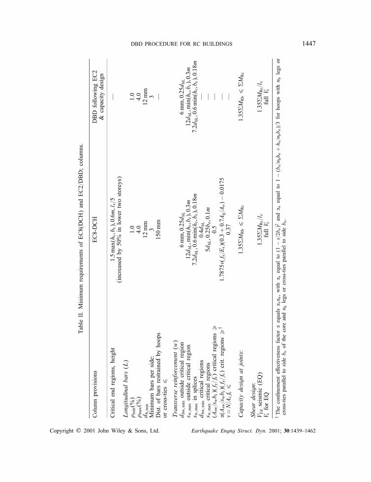
DBD PROCEDURE FOR RC BUILDINGS 1447
Tab
leII.M
inim
umrequ
irem
ents
ofEC8(DCH)an
dEC2=DBD;co
lumns
.
Colum
nprov
isions
EC8-DCH
DBD
follo
wing
EC2
&ca
pacity
design
Critic
alen
dregion
s,he
ight
1:5max
(hc;b c);0:6m
;lc=5
—(inc
reased
by50
%in
lower
two
storey
s)Longitudinalbars
(L)
� min(%
)1.0
1.0
� max(%
)4.0
4.0
d b;m
in12
mm
12mm
Minim
umba
rspe
rside
:3
3Dist.
ofba
rsrestrained
byho
ops
150mm
—or
cros
s-tie
s6
Transversereinforcem
ent(w
)d b
w;m
inou
tsidecritica
lregion
6mm
;0:25d
bL6mm
;0:25d
bLs w
;max
outsidecritica
lregion
12d b
L;m
in(h
c;b c);0:3m
12d b
L;m
in(h
c;b c);0:3m
s w;m
axin
splic
es7:2d
bL;0
:6min(h
c;b c);0:18
m7:2d
bL;0
:6min(h
c;b c);0:18
md b
w;m
incritica
lregion
s0:4d
bL—
s w;m
axcritica
lregion
s5d
bL;0
:25b
o;0:1m
—(A
sw=s
wb c)(
f y=f
c)critica
lregion
s¿
0.5
—�(
Asw
=swb c)(
f y=f
c)crit.
region
s¿
†1:78
75�(
f y=E
s)(0
:3+
0:7A
g=A
o)−
0:01
75—
�=
N=A
cfc6
0.37
—
Capacitydesign
atjoints:
1:35
RM
Rb6
RM
Rc
1:35
RM
Rb6
RM
Rc
Shear
design
:V
Edseismic
(EQ)
1:35
RM
Rc=l c
1:35
RM
Rc=l c
V cforEQ
full
V cfull
V c
†The
con@
nemen
teE
ectiv
enessfactor
�eq
uals
� s� n
,with
� seq
ualto
(1−
s=2b
o)2
and
� neq
ualto
1−
(bo=n
hh o
+h o
=nbb o
)=3
forho
opswith
n blegs
orcros
s-tie
spa
ralle
lto
side
b oof
theco
rean
dn h
legs
orcros
s-tie
spa
ralle
lto
side
b o.
Copyright ? 2001 John Wiley & Sons, Ltd. Earthquake Engng Struct. Dyn. 2001; 30:1439–1462
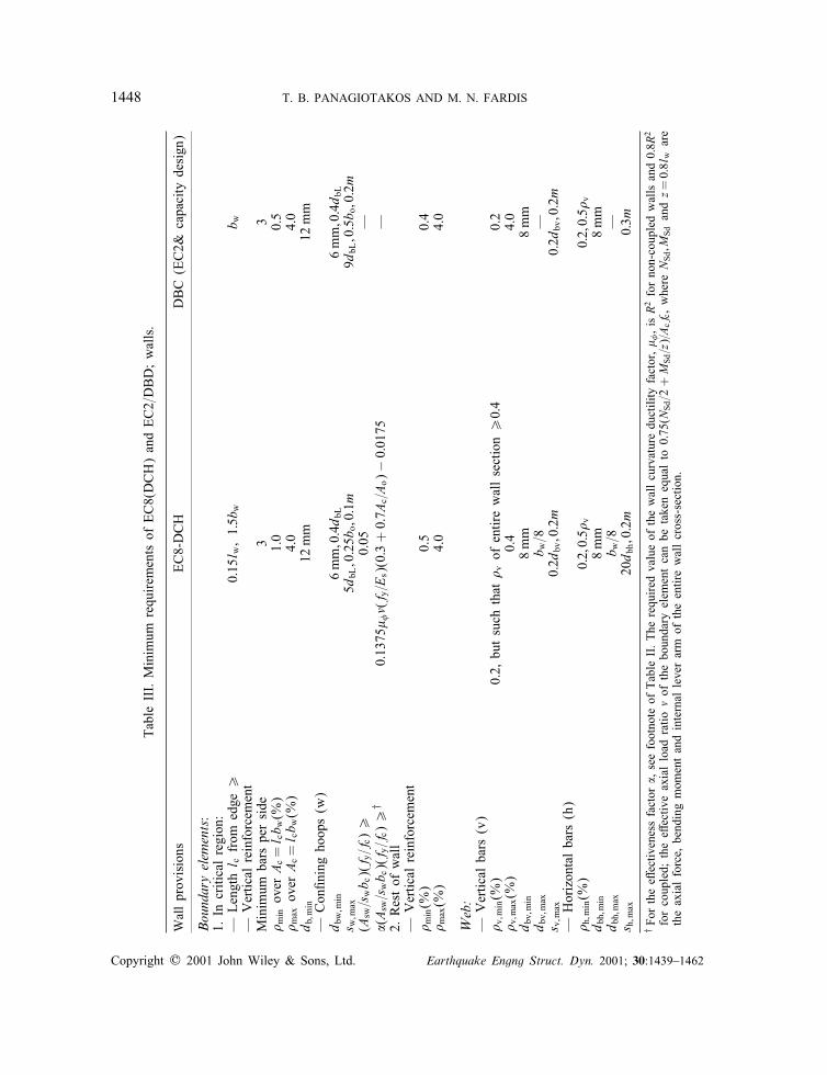
1448 T. B. PANAGIOTAKOS AND M. N. FARDIS
Tab
leIII.
Minim
umrequ
irem
ents
ofEC8(DCH)an
dEC2=DBD;walls.
Wallprov
isions
EC8-DCH
DBC
(EC2&
capa
city
design
)
Boundaryelem
ents:
1.In
critica
lregion
:—
Len
gth
l cfrom
edge¿
0:15
l w;1:5b
wb w
—Vertic
alreinforcem
ent
Minim
umba
rspe
rside
33
� min
over
Ac=
l cb w
(%)
1.0
0.5
� max
over
Ac=
l cb w
(%)
4.0
4.0
d b;m
in12
mm
12mm
—Con
@ning
hoop
s(w
)d b
w;m
in6mm
;0:4d b
L6mm
;0:4d b
Ls w
;max
5dbL
;0:25b
o;0:1m
9dbL
;0:5b o
;0:2m
(Asw
=swb c)(
f y=f
c)¿
0.05
—�(
Asw
=swb c)(
f y=f
c)¿
†0:13
75�
�(f y
=Es)(0
:3+
0:7A
c=A
o)−
0:01
75—
2.Restof
wall
—Vertic
alreinforcem
ent
� min(%
)0.5
0.4
� max(%
)4.0
4.0
Web:
—Vertic
alba
rs(v)
� v;m
in(%
)0.2,
butsu
chthat
� vof
entir
ewallsection¿
0:4
0.2
� v;m
ax(%
)0.4
4.0
d bv;
min
8mm
8mm
d bv;
max
b w=8
—s v
;max
0:2d
bv;0
:2m
0:2d
bv;0
:2m
—Horizon
talba
rs(h)
� h;m
in(%
)0:2;0:5�
v0:2;0:5�
vd b
h;min
8mm
8mm
d bh;
max
b w=8
—s h
;max
20d b
h;0
:2m
0:3m
†Fo
rtheeE
ectiv
enessfactor
�,seefootno
teof
Tab
leII.The
requ
ired
valueof
thewallcu
rvaturedu
ctility
factor,�
,is
R2forno
n-co
upledwalls
and0:8R
2
forco
upled;
theeE
ectiv
eax
ialload
ratio
�of
thebo
unda
ryelem
entcan
betake
neq
ualto
0:75
(NSd
=2+
MSd
=z)=Acf
c,whe
reN
Sd;M
Sdan
dz=
0:8l
ware
theax
ialforce,
bend
ing
mom
entan
dinternal
leve
rarm
oftheen
tirewallcros
s-section.
Copyright ? 2001 John Wiley & Sons, Ltd. Earthquake Engng Struct. Dyn. 2001; 30:1439–1462

DBD PROCEDURE FOR RC BUILDINGS 1449
the sum of bending moments at the base of the individual walls, allowing for these walls toqualify as coupled. According to the elastic analysis the walls take more than 70 per cent ofthe seismic base shear.
In both designs the load combinations are according to EC2 [24] and EC8 [18], i.e. (a)1:35× dead load+1:5× live load for factored gravity and (b) earthquake+dead load+0:3× liveload for the seismic combination.
The designs according to EC8 or step 1 of the DBD procedure follow the sequence outlinedin Section 2.1, as described in detail below:
(a) Beams were proportioned in Cexure for the envelope of the moments from the loadcombinations: (i) of factored gravity loads; and (ii) of earthquake plus ‘arbitrary-point-in-time’gravity loads (dead-load+0:3× live-load according to EC8). As the ‘serviceability’ earthquakeof the DBD frame and the reduced by R=5 design earthquake of the EC8 frame are the same,longitudinal steel requirements for the beams of both frames are the same.
The upper limit to the diameter of beam bars passing through beam-column joints, asdetermined by bar development within the joint (lines 11 and 12 in Table III) is 12 mm inthe EC8 frame and 14mm in the DBD one. Bar development within the beam-wall joints setspractically no limit to the beam bar diameter.
The minimum reinforcement ratio is 0:5fct=fy = 0:26 per cent for the EC8 beams, but 0.15per cent for the DBD ones. So the minimum reinforcement is three 12 mm bars for the EC8beams and two 12 mm beams for the DBD ones.
EC8 allows counting in the top beam reinforcement any slab bars which are parallel to thebeam and up to a distance bf from it equal to twice the slab depth hf on each side of thebeam, for exterior columns with transverse beams or interior ones without such beams, orup to bf = 4hf on each side of the beam, for interior columns with transverse beams. In theprototype structure, with the slab extending to both sides of the beams, this rule gives a slabcontribution to the top beam reinforcement of 560 or 200 mm2 at the face of the interior orthe exterior column, respectively, or of 170 mm2 at the face of the walls.
Over the interior column supports the minimum steel suNces as top reinforcement in bothdesigns, without any contribution from the slab reinforcement. Over beam supports at theexterior column and at the interior wall the minimum reinforcement plus the above quantitiesof slab steel barely meet the requirements for beam top reinforcement in the three lowerCoors. As a matter of fact, the reinforcement there meets the requirements with some de@citin the DBD frame, which has less minimum beam reinforcement than the EC8 one. Theminimum reinforcement suNces throughout the bottom of all beams, except those of the twolower storeys of the DBD frame, where it needs to be increased to two 14 mm bars.
The minimum longitudinal reinforcement of two 14 mm bars in the EC8 design or two12mm bars in the DBD one suNces in the coupling beams. The maximum shear in the EC8coupling beams (from the analysis or from capacity design, see (b) below, including 170mm2
of slab steel in the calculation of the beam Cexural capacity), barely reaches the EC8 limitfor placement of bars along the two diagonals of the beam.
(b) Beam stirrups were proportioned for capacity design shears calculated on the basis ofoverstrength Cexural capacities 1:25MRb at beam ends, plus transverse ‘arbitrary-point-in-time’gravity loads. Beam Cexural capacities were determined including some slab reinforcementaccording to EC8, i.e. up to a distance bf = 2hf on each side of the beam, except at the faceof interior columns, where bf = 4hf on each side of the beam can be taken.
Copyright ? 2001 John Wiley & Sons, Ltd. Earthquake Engng Struct. Dyn. 2001; 30:1439–1462
1450 T. B. PANAGIOTAKOS AND M. N. FARDIS
Over 1:5hb = 0:675 m-long critical end regions of the DBD beams, where the concretecontribution to shear resistance Vc is neglected, 8 mm stirrups at 225 centres are required inthe two upper Coors or at 210 mm centres in the two lower Coors. This stirrup spacing isrequired on both sides of the joint with the interior column, where the slab contribution tothe beam Cexural capacity is the largest and penalizes the capacity design shears the most.This spacing could be increased a little at the other end of these DBD beams, but it was keptthe same at both ends for simplicity.
Over the 2hb = 0:9 m-long critical end regions of EC8 beams the antibuckling requirementsw;max =5dbL =60 mm controls the stirrup spacing.
In-between the critical end regions the maximum stirrup spacing of 0:3 m controls in bothdesigns.
Stirrup spacing in the coupling beams of the DBD frame is controlled by the capacity designshear force. It is equal to 120 mm in the two upper Coors and 105 mm in the other two. Inthe coupling beams of the EC8 frame the stirrup spacing required to resist the capacity designshear is 95 mm, but the antibuckling requirement sw;max =5dbL =50 mm controls. Since theEC8 coupling beams were at the limit of requiring diagonal reinforcement, the stirrup spacingwas reduced to 50 mm in the coupling beam of the (most critical) 1st Coor.
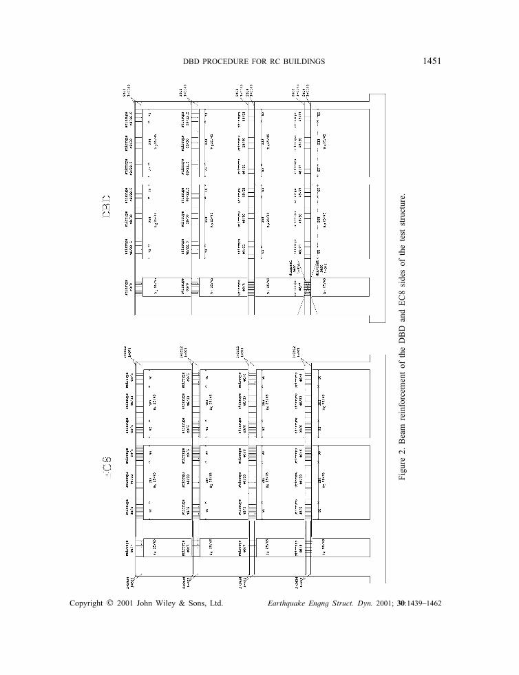
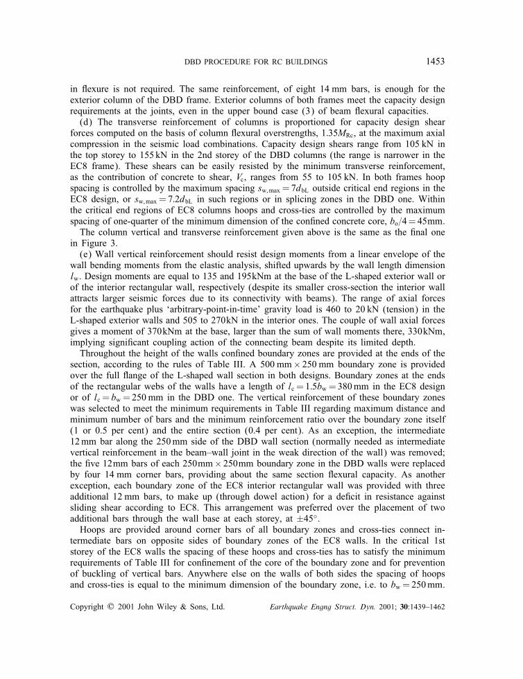
The (@nal) beam reinforcement shown in Figure 2 diEers from what is given above onlyin the coupling beams of the DBD frame, because there step 3 of the DBD procedure resultsin more closely spaced stirrups and in placement of some diagonal bars.
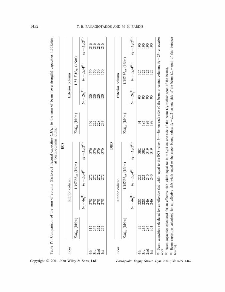
(c) Columns were proportioned in Cexure, so that the sum of their factored Cexural capac-ities at beam column joints, RMRc, exceeds the sum of overstrength capacities of the beams,1:35RMRb. The values of 1:35RMRb listed in Table IV are calculated on the basis of threealternative considerations for the slab width bf contributing with its tension steel to the hog-ging Cexural capacity of the beam: (1) for bf according to the EC8 values quoted above andconsidered on both sides of the beam (i.e. as in the prototype structure); (2) for bf accordingto the more realistic estimate of the New Zealand code, i.e. equal to one-quarter of the beamspan Lb, but only on one side of the beam, i.e. as in the test structure; and (3) for bf equalto the physical upper bound of one-half of the clear distance Ls of the two frames in the teststructure. Beam Cexural capacities resulting from consideration (1) are practically the sameas those from (2) at the interior column joint, but are 20–25 per cent lower at the exteriorcolumn joint. Beam Cexural capacities from the upper bound consideration (3) are 40–50 percent higher than the ones from (2).
To meet the limitations on minimum number and maximum distance of bars around thecolumn section, a minimum of 10 or 8 bars is required in the EC8 and the DBD columns,respectively. With these numbers 12 or 14 mm bars would be enough in the EC8 and theDBD columns, respectively, to supply the minimum reinforcement ratio of 1 per cent. (Theminimum reinforcement ratio for EC2 columns is 0.3 per cent, but the 1 per cent value ofEC8 is considered here necessary for earthquake-resistant columns and adopted in the DBDapproach.) In the interior columns of the EC8 and the DBD frames ten 14mm bars and eight16 mm ones, respectively, are needed to meet or exceed the beam overstrength capacitiesfrom considerations (1) and (2), for the minimum column axial force in the seismic loadcombinations. Vertical reinforcement in the exterior column of the EC8 frame is the same asin the interior one, because ten 12mm bars are barely enough in the weak direction of bendingagainst factored gravity loads in the test structure. At the interior column of the DBD framethe bar diameter can be reduced to 14mm at the 4th Coor, where capacity design of columns
Copyright ? 2001 John Wiley & Sons, Ltd. Earthquake Engng Struct. Dyn. 2001; 30:1439–1462
DBD PROCEDURE FOR RC BUILDINGS 1451
Figu
re2.
Bea
mreinforcem
entof
theDBD
and
EC8
side
sof
thetest
structure.
Copyright ? 2001 John Wiley & Sons, Ltd. Earthquake Engng Struct. Dyn. 2001; 30:1439–1462
1452 T. B. PANAGIOTAKOS AND M. N. FARDIS
Tab
leIV
.Com
pariso
nof
thesu
mof
column
(fac
tored)
Cexu
ralca
pacitie
sRM
Rc,
tothesu
mof
beam
(ove
rstren
gth)
capa
citie
s1:35
RM
Rb
atbe
am-colum
njoints.
EC8
Floo
rInterior
column
Exteriorco
lumn
RM
Rc(kNm)
1:35
RM
Rb(kNm)
RM
Rc(kNm)
1.35
RM
Rb(kNm)
b f=
4h(1)
fb f
=L b
=4(2)
b f=
L s=2
(3)
b f=
2h(1)
fb f
=L b
=4(2)
b f=
L s=2
(3)
4th
117
278
272
376
109
120
150
216
3rd
244
278
272
376
222
120
150
216
2nd
262
278
272
376
228
120
150
216
1st
277
278
272
376
233
120
150
216
DBD
Floo
rInterior
column
Exteriorco
lumn
RM
Rc(kNm)
1:35
RM
Rb(kNm)
RM
Rc(kNm)
1:35
RM
Rb(kNm)
b f=
4h(1)
fb f
=L b
=4(2)
b f=
L s=2
(3)
b f=
2h(1)
fb f
=L b
=4(2)
b f=
L s=2
(3)
4th
9922
822
130
291
9512
519
03rd
236
228
221
302
186
9512
519
02n
d28
424
624
031
919
395
125
190
1st
301
246
240
319
199
9512
519
0
(1)Beam
capa
citie
scalculated
foran
eEectiv
eslab
width
equa
lto
theEC8va
lue:
b f=
4hfon
each
side
ofthebe
amat
centralco
lumns
;b f
=2h
fat
exterior
ones.
(2)Beam
capa
citie
scalculated
foran
eEectiv
eslab
width
equa
lto:b f
=L b
=4on
oneside
ofthebe
am(L
b=
clearsp
anof
thebe
am).
(3)Beam
capa
citie
scalculated
foran
eEectiv
eslab
width
equa
lto
theup
perbo
und
value:
b f=
L s=2
onon
eside
ofthebe
am(L
s=
span
ofslab
betw
een
beam
s).
Copyright ? 2001 John Wiley & Sons, Ltd. Earthquake Engng Struct. Dyn. 2001; 30:1439–1462
DBD PROCEDURE FOR RC BUILDINGS 1453
in Cexure is not required. The same reinforcement, of eight 14 mm bars, is enough for theexterior column of the DBD frame. Exterior columns of both frames meet the capacity designrequirements at the joints, even in the upper bound case (3) of beam Cexural capacities.
(d) The transverse reinforcement of columns is proportioned for capacity design shearforces computed on the basis of column Cexural overstrengths, 1:35MRc, at the maximum axialcompression in the seismic load combinations. Capacity design shears range from 105 kN inthe top storey to 155 kN in the 2nd storey of the DBD columns (the range is narrower in theEC8 frame). These shears can be easily resisted by the minimum transverse reinforcement,as the contribution of concrete to shear, Vc, ranges from 55 to 105 kN. In both frames hoopspacing is controlled by the maximum spacing sw;max =7dbL outside critical end regions in theEC8 design, or sw;max =7:2dbL in such regions or in splicing zones in the DBD one. Withinthe critical end regions of EC8 columns hoops and cross-ties are controlled by the maximumspacing of one-quarter of the minimum dimension of the con@ned concrete core, bo=4=45mm.
The column vertical and transverse reinforcement given above is the same as the @nal onein Figure 3.
(e) Wall vertical reinforcement should resist design moments from a linear envelope of thewall bending moments from the elastic analysis, shifted upwards by the wall length dimensionlw. Design moments are equal to 135 and 195kNm at the base of the L-shaped exterior wall orof the interior rectangular wall, respectively (despite its smaller cross-section the interior wallattracts larger seismic forces due to its connectivity with beams). The range of axial forcesfor the earthquake plus ‘arbitrary-point-in-time’ gravity load is 460 to 20 kN (tension) in theL-shaped exterior walls and 505 to 270kN in the interior ones. The couple of wall axial forcesgives a moment of 370kNm at the base, larger than the sum of wall moments there, 330kNm,implying signi@cant coupling action of the connecting beam despite its limited depth.
Throughout the height of the walls con@ned boundary zones are provided at the ends of thesection, according to the rules of Table III. A 500 mm× 250 mm boundary zone is providedover the full Cange of the L-shaped wall section in both designs. Boundary zones at the endsof the rectangular webs of the walls have a length of lc = 1:5bw =380mm in the EC8 designor of lc = bw =250mm in the DBD one. The vertical reinforcement of these boundary zoneswas selected to meet the minimum requirements in Table III regarding maximum distance andminimum number of bars and the minimum reinforcement ratio over the boundary zone itself(1 or 0.5 per cent) and the entire section (0.4 per cent). As an exception, the intermediate12mm bar along the 250mm side of the DBD wall section (normally needed as intermediatevertical reinforcement in the beam–wall joint in the weak direction of the wall) was removed;the @ve 12mm bars of each 250mm× 250mm boundary zone in the DBD walls were replacedby four 14 mm corner bars, providing about the same section Cexural capacity. As anotherexception, each boundary zone of the EC8 interior rectangular wall was provided with threeadditional 12 mm bars, to make up (through dowel action) for a de@cit in resistance againstsliding shear according to EC8. This arrangement was preferred over the placement of twoadditional bars through the wall base at each storey, at ±45◦.
Hoops are provided around corner bars of all boundary zones and cross-ties connect in-termediate bars on opposite sides of boundary zones of the EC8 walls. In the critical 1ststorey of the EC8 walls the spacing of these hoops and cross-ties has to satisfy the minimumrequirements of Table III for con@nement of the core of the boundary zone and for preventionof buckling of vertical bars. Anywhere else on the walls of both sides the spacing of hoopsand cross-ties is equal to the minimum dimension of the boundary zone, i.e. to bw =250mm.
Copyright ? 2001 John Wiley & Sons, Ltd. Earthquake Engng Struct. Dyn. 2001; 30:1439–1462
1454 T. B. PANAGIOTAKOS AND M. N. FARDIS
Figu
re3.
Reinforce
men
tof
vertical
elem
ents
ofDBD
and
EC8
side
sof
thetest
structure.
Copyright ? 2001 John Wiley & Sons, Ltd. Earthquake Engng Struct. Dyn. 2001; 30:1439–1462
DBD PROCEDURE FOR RC BUILDINGS 1455
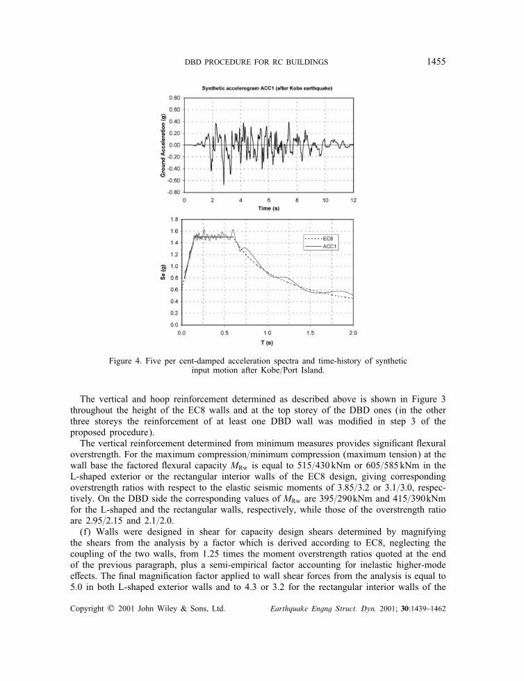
Figure 4. Five per cent-damped acceleration spectra and time-history of syntheticinput motion after Kobe=Port Island.
The vertical and hoop reinforcement determined as described above is shown in Figure 3throughout the height of the EC8 walls and at the top storey of the DBD ones (in the otherthree storeys the reinforcement of at least one DBD wall was modi@ed in step 3 of theproposed procedure).
The vertical reinforcement determined from minimum measures provides signi@cant Cexuraloverstrength. For the maximum compression=minimum compression (maximum tension) at thewall base the factored Cexural capacity MRw is equal to 515=430kNm or 605=585kNm in theL-shaped exterior or the rectangular interior walls of the EC8 design, giving correspondingoverstrength ratios with respect to the elastic seismic moments of 3:85=3:2 or 3:1=3:0, respec-tively. On the DBD side the corresponding values of MRw are 395=290kNm and 415=390kNmfor the L-shaped and the rectangular walls, respectively, while those of the overstrength ratioare 2:95=2:15 and 2:1=2:0.
(f) Walls were designed in shear for capacity design shears determined by magnifyingthe shears from the analysis by a factor which is derived according to EC8, neglecting thecoupling of the two walls, from 1.25 times the moment overstrength ratios quoted at the endof the previous paragraph, plus a semi-empirical factor accounting for inelastic higher-modeeEects. The @nal magni@cation factor applied to wall shear forces from the analysis is equal to5.0 in both L-shaped exterior walls and to 4.3 or 3.2 for the rectangular interior walls of the
Copyright ? 2001 John Wiley & Sons, Ltd. Earthquake Engng Struct. Dyn. 2001; 30:1439–1462
1456 T. B. PANAGIOTAKOS AND M. N. FARDIS
EC8 and the DBD side, respectively. After this magni@cation design shears in the 1st storey ofthe L-shaped walls for the extremes of compression and tension are equal to 280 and 215kN,respectively, on the EC8 side or to 265 and 150 kN on the DBD side. In the rectangularinterior walls, which do not develop tensile axial forces under the seismic load combination,design shear forces at the 1st storey are equal to 370 or 275 kN on the EC8 and the DBDside, respectively. Design shears at the 2nd storey are 85 or 75 per cent respectively, of thevalues above for the L-shaped exterior walls and the interior rectangular ones, respectively.
At all storeys of the EC8 and DBD walls the minimum horizontal reinforcement of 8 mmbars at 160 mm centres (20 times the bar diameter), or at 200 mm centres (giving a webreinforcement ratio of 0.2 per cent) was, respectively, provided. For a 45◦-truss these rein-forcements give factored shear capacities of 220 or 175 kN, respectively. These capacitiessuNce against the design shear of the exterior L-shaped walls under tensile axial load, i.e.when at the critical 1st storey the contribution of concrete to shear resistance, Vc, is neglected.For compressive axial forces the factored shear capacity of concrete, Vc, is equal to 85 or80 kN in the 1st storey of the EC8 or the DBD wall, respectively; then the total factoredshear capacity exceeds the design shear force only in the L-shaped exterior walls of the EC8side. Everywhere else in the 1st storey under peak axial compression there is a shear strengthde@cit ranging from 19 per cent in the rectangular wall of the EC8 side, to 7:5 or 4 per centin the rectangular and L-shaped walls of the DBD side. Nevertheless, as the EC8 rules forthe shear force magni@cation in walls are deemed to be overly conservative, these de@citsmay be considered acceptable.
The vertical reinforcement in the webs of the DBD walls was selected to be the same asthe horizontal (i.e. equal to the minimum). The two 8 mm bars placed on each side of theweb of the EC8 walls between the two boundary zones provide 50 per cent more verticalweb reinforcement than the minimum. For the value of the shear span ratio M=Vlw prevailingin these walls (around 1.6) wall axial compression is considered to assist the web verticalreinforcement in shear; hence, there is a surplus of web vertical steel in all four walls,especially in those of the EC8 side.
It is clear that both the EC8 design and that from step 1 of the DBD procedure arenot controlled by ULS proportioning for the ‘serviceability’ earthquake. They are controlledinstead by capacity design, minimum reinforcement and detailing rules and sometimes byfactored gravity loads.
The changes in the reinforcement of the DBD side eEected within step 3 of the proposedapproach (with �=1:2 in Equation (5)) to meet the chord rotation demands from step 2 arethe following:
(i) The spacing of stirrups in the coupling beams was reduced from 120 to 80 mm in thetwo upper Coors and from 105 to 50mm in the two lower ones, while two 20mm barswere placed along each diagonal of the coupling beam of the 1st Coor.
(ii) In the 1st storey of the interior rectangular wall and in the three lower storeys of theexterior L-shaped ones, hoop spacing in the boundary zones was reduced from 250 to60 mm and the diameter of the four corner bars in all boundary zones other than thatof the Cange of the L-shaped wall was increased from 14 to 16 mm.
The increase in the vertical reinforcement of the DBD walls increases their Cexural capacityand in turn the overstrength ratio over the elastic moments at the base from the analysis for
Copyright ? 2001 John Wiley & Sons, Ltd. Earthquake Engng Struct. Dyn. 2001; 30:1439–1462
DBD PROCEDURE FOR RC BUILDINGS 1457
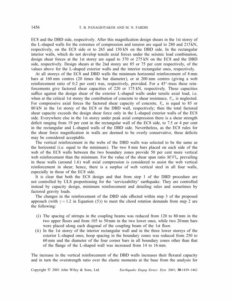
Table V. Comparison of steel quantities per frame (kg) in the two designs.
Floor Longitudinal Transverse Total
EC8 DBD DiEerence EC8 DBD DiEerence EC8 DBD DiEerence(%) (%) (%)
Beams and coupling beams4 66 41 −38 45 22 −51 111 63 −433 66 41 −38 45 22 −51 111 63 −432 66 48 −27 45 26 −42 111 74 −331 66 48 −27 46 26 −44 112 74 −34Total 264 178 −33 181 96 −47 445 274 −38
Columns4 74 59 −20 84 51 −39 158 110 −303 87 80 −8 84 49 −42 171 129 −252 87 80 −8 100 49 −51 187 129 −311 128 118 −8 117 57 −51 245 175 −29Total 376 337 −10 385 206 −45 761 543 −29
Walls4 110 70 −36 74 54 −27 184 124 −333 130 88 −32 74 56 −24 204 144 −292 160 88 −32 74 56 −24 204 144 −291 191 146 −24 167 66 −61 358 212 −41Total 561 392 −30 386 232 −40 950 624 −34
maximum=minimum axial compression from 2:95=2:15 and 2:1=2:0 in the L-shaped exteriorwall and the interior rectangular one, respectively, to 4:2=2:15 and 3:0=2:85. The new Cexuraloverstrength ratios are similar to those of the EC8 walls. The increase in Cexural overstrengthat the base increases also capacity design shears in the DBD walls. In the rectangular interiorwall the design shear increases to 350 kN at the 1st storey and to 265 kN at the 2nd. Theavailable shear strength of the 2nd storey is marginal, while that of the 1st storey is de@cientby about 35 per cent. Correction of this de@ciency requires reduction of the spacing of thehorizontal reinforcement from 200 to 110 mm. Nevertheless, as the capacity design shears ofEC8 are considered overconservative, it was decided to keep the shear reinforcement in theDBD walls unchanged.
Horizontal reinforcement in the joints, consisting of perimeter hoops alone, was determinedat this stage according to EC8 rules on the basis of the cross-sectional area of beam barscrossing the joints. As the beam longitudinal reinforcement was not revised in step 3, pro-portioning of the joint reinforcement could have been accomplished at the end of step 1.Indeed, as the longitudinal reinforcement in the EC8 and the DBD beams is similar, jointreinforcement in both designs is the same.
The @nal reinforcement of the DBD design is compared in Figures 2 and 3 to that ofthe EC8 design. Table V compares the weight of steel required for one frame according tothe two designs, per type of element and Coor and separately for the longitudinal and thetransverse reinforcement. For all types of elements the DBD frame requires signi@cantly lesssteel than the EC8 one. Overall the diEerence amounts to one-third of the EC8 requirements.The diEerence is largest in the transverse reinforcement, where the DBD frame requires almosthalf the reinforcement of the EC8 design.
Copyright ? 2001 John Wiley & Sons, Ltd. Earthquake Engng Struct. Dyn. 2001; 30:1439–1462

1458 T. B. PANAGIOTAKOS AND M. N. FARDIS
3.2. Nonlinear dynamic analyses of the test structure
In the actual 4-storey test structure one of the two frames has been constructed according tothe EC8 design and the other according to the DBD one. In the PSD test the two frames aresubjected to the same horizontal displacement time-histories at Coor levels.
Non-linear dynamic response analyses were performed for the structure as tested, i.e. withthe one side according to DBD and the other according to EC8, using as input @ve syntheticmotions conforming to 1.5 times the elastic spectrum of the ‘design’ earthquake. Each mo-tion was applied with a positive or negative sign (direction). The @ve motions, drawn fromReference [25], have phasing and intensity envelopes after some well-known historic records,namely that of Kobe=Port Island, Hollister (1961), San Fernando=Alhambra and FairmontReservoir (1971) and Imperial Valley=El Centro (1940). The synthetic motion ‘after’ Kobewas selected for the PSD test. Its time-history and the corresponding 5 per cent-damped elasticspectra are shown in Figure 4, including the 1.5 scale factor over the ‘design’ earthquake.
The nonlinear analyses employ simple lumped-inelasticity member models, of the one-component type with bilinear skeleton curve and modi@ed-Takeda hysteresis laws. The mod-elling used has been presented in more detail elsewhere [26; 27]. Material strengths wereassumed to be equal to their expected values: fcm =fc + 8MPa=33MPa and fym =1:15fy =575 MPa.
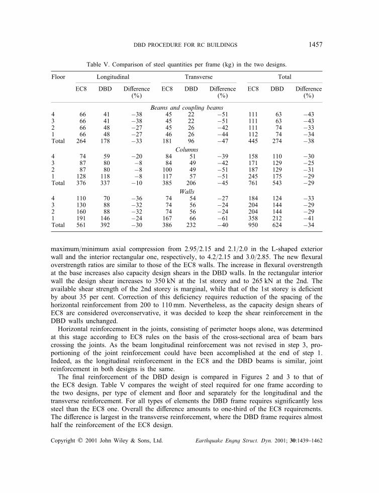
Figure 5 shows the average ratio of member peak inelastic chord rotations from the non-linear dynamic analyses to the corresponding supply from Equation (3). As this ratio can beconsidered as a damage ratio, it is presented as a percentage, with a value of 100 per centmeaning exhaustion of expected member deformation capacity. Averaging is over the 10 non-linear dynamic analyses, with the @ve synthetic motions applied in the positive and negativedirections at intensity 1.5 times the design motion. The same @gure presents the average andthe extreme values of the interstorey and top drift ratios obtained in the 10 analyses. Despiteits signi@cantly lower amount of steel the DBD frame is predicted to experience similar mem-ber damage levels as the EC8 one and to fare on the average better than the EC8 frame inthe coupling beams.
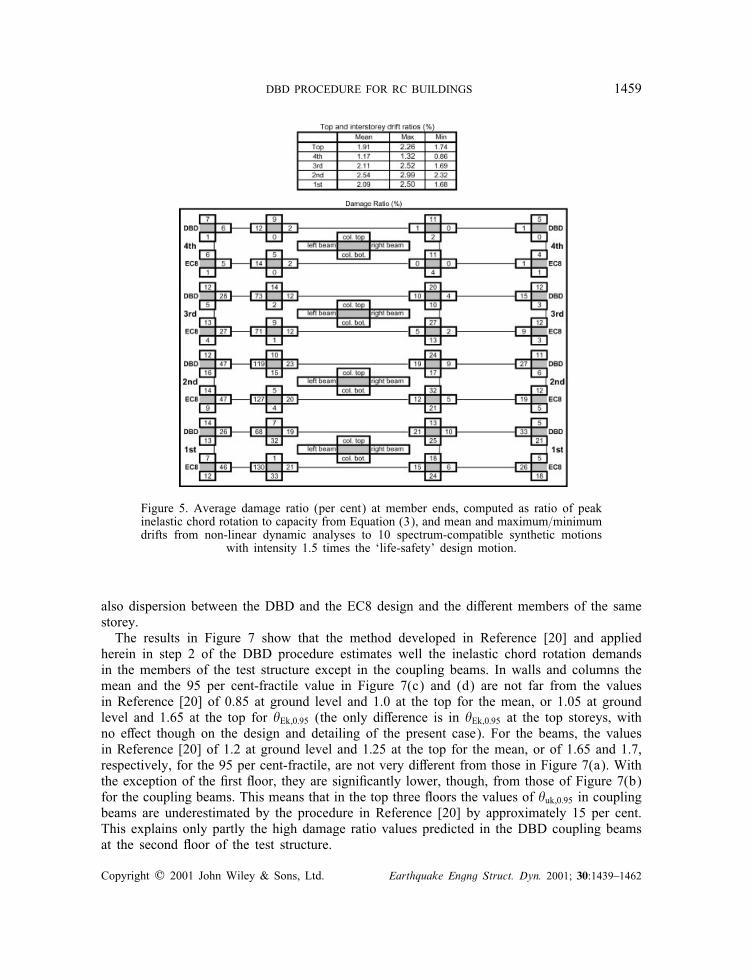
Figure 6 presents analysis results for the motion of Figure 4 applied in the PSD test. Floordisplacement time-histories and peak interstorey drifts from pre-test calculations based onassumed mean material strengths consistent with the speci@ed nominal values, are comparedwith test results. The test results may have been aEected by the damage inCicted to the teststructure by previous testing at the ‘design’ motion intensity.
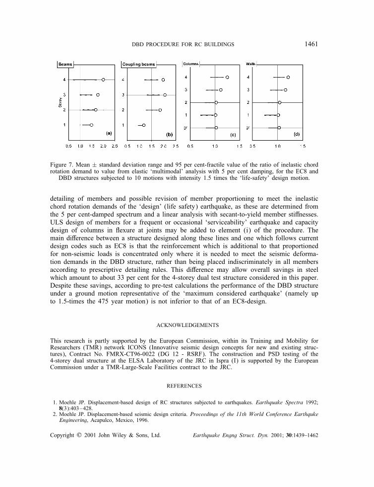
In the analyses summarized in Figures 5 and 6 the DBD-side coupling beams of the 2ndCoor were predicted to fail under 1.5 times the ‘design’ earthquake. At @rst sight this issurprising, as for �=1:2 the combination of Equations (4) and (5) seems to provide a safetyfactor against attainment of �Ek;0:95 equal to 1:2=0:45=2:67, which should not be exhaustedby the application of the ‘design’ motion at a scale factor of 1:5. To investigate the originof this apparent discrepancy, the member inelastic chord rotations, �E;in, from the non-linearanalyses of the response of the two structures designed herein (i.e. of the EC8 and theDBD building) to 10 input motions (5 motions applied with a plus or minus sign), arecompared to the elastic values, �Em, computed in step 2 of the proposed procedure accordingto Reference [20]. Mean ± standard deviation ranges and the 95 per cent-fractile of the ratio�E;in=�Em are shown in Figure 7. The m ± ! range and the diEerence of the 95 per cent-fractile from the mean reCect not only the inCuence of the details of the input motion, but
Copyright ? 2001 John Wiley & Sons, Ltd. Earthquake Engng Struct. Dyn. 2001; 30:1439–1462
DBD PROCEDURE FOR RC BUILDINGS 1459
Figure 5. Average damage ratio (per cent) at member ends, computed as ratio of peakinelastic chord rotation to capacity from Equation (3), and mean and maximum=minimumdrifts from non-linear dynamic analyses to 10 spectrum-compatible synthetic motions
with intensity 1.5 times the ‘life-safety’ design motion.
also dispersion between the DBD and the EC8 design and the diEerent members of the samestorey.
The results in Figure 7 show that the method developed in Reference [20] and appliedherein in step 2 of the DBD procedure estimates well the inelastic chord rotation demandsin the members of the test structure except in the coupling beams. In walls and columns themean and the 95 per cent-fractile value in Figure 7(c) and (d) are not far from the valuesin Reference [20] of 0.85 at ground level and 1.0 at the top for the mean, or 1.05 at groundlevel and 1.65 at the top for �Ek;0:95 (the only diEerence is in �Ek;0:95 at the top storeys, withno eEect though on the design and detailing of the present case). For the beams, the valuesin Reference [20] of 1.2 at ground level and 1:25 at the top for the mean, or of 1.65 and 1.7,respectively, for the 95 per cent-fractile, are not very diEerent from those in Figure 7(a). Withthe exception of the @rst Coor, they are signi@cantly lower, though, from those of Figure 7(b)for the coupling beams. This means that in the top three Coors the values of �uk;0:95 in couplingbeams are underestimated by the procedure in Reference [20] by approximately 15 per cent.This explains only partly the high damage ratio values predicted in the DBD coupling beamsat the second Coor of the test structure.
Copyright ? 2001 John Wiley & Sons, Ltd. Earthquake Engng Struct. Dyn. 2001; 30:1439–1462
1460 T. B. PANAGIOTAKOS AND M. N. FARDIS
Figure 6. Computed and measured Coor displacement time-histories and interstorey driftsand computed damage ratio (per cent) at member ends for test structure subjected to
‘Kobe-like’ motion at intensity 1.5 times the ‘life-safety’ motion, Figure 4.
4. CONCLUSIONS
The key elements of the proposed procedure for displacement-based seismic design of RCframe-wall dual building structures are the following: (i) a preliminary proportioning of mem-ber reinforcement on the basis of the ULS for factored gravity loads, capacity design of allelements in shear and detailing provisions for non-earthquake-resistant design; and (ii) @nal
Copyright ? 2001 John Wiley & Sons, Ltd. Earthquake Engng Struct. Dyn. 2001; 30:1439–1462
DBD PROCEDURE FOR RC BUILDINGS 1461
Figure 7. Mean ± standard deviation range and 95 per cent-fractile value of the ratio of inelastic chordrotation demand to value from elastic ‘multimodal’ analysis with 5 per cent damping, for the EC8 and
DBD structures subjected to 10 motions with intensity 1.5 times the ‘life-safety’ design motion.
detailing of members and possible revision of member proportioning to meet the inelasticchord rotation demands of the ‘design’ (life safety) earthquake, as these are determined fromthe 5 per cent-damped spectrum and a linear analysis with secant-to-yield member stiEnesses.ULS design of members for a frequent or occasional ‘serviceability’ earthquake and capacitydesign of columns in Cexure at joints may be added to element (i) of the procedure. Themain diEerence between a structure designed along these lines and one which follows currentdesign codes such as EC8 is that the reinforcement which is additional to that proportionedfor non-seismic loads is concentrated only where it is needed to meet the seismic deforma-tion demands in the DBD structure, rather than being placed indiscriminately in all membersaccording to prescriptive detailing rules. This diEerence may allow overall savings in steelwhich amount to about 33 per cent for the 4-storey dual test structure considered in this paper.Despite these savings, according to pre-test calculations the performance of the DBD structureunder a ground motion representative of the ‘maximum considered earthquake’ (namely upto 1.5-times the 475 year motion) is not inferior to that of an EC8-design.
ACKNOWLEDGEMENTS
This research is partly supported by the European Commission, within its Training and Mobility forResearchers (TMR) network ICONS (Innovative seismic design concepts for new and existing struc-tures), Contract No. FMRX-CT96-0022 (DG 12 - RSRF). The construction and PSD testing of the4-storey dual structure at the ELSA Laboratory of the JRC in Ispra (I) is supported by the EuropeanCommission under a TMR-Large-Scale Facilities contract to the JRC.
REFERENCES
1. Moehle JP. Displacement-based design of RC structures subjected to earthquakes. Earthquake Spectra 1992;8(3):403–428.
2. Moehle JP. Displacement-based seismic design criteria. Proceedings of the 11th World Conference EarthqukeEngineering, Acapulco, Mexico, 1996.
Copyright ? 2001 John Wiley & Sons, Ltd. Earthquake Engng Struct. Dyn. 2001; 30:1439–1462
1462 T. B. PANAGIOTAKOS AND M. N. FARDIS
3. New Zealand National Society for Earthquake Engineering. The assessment and improvement of the structuralperformance of earthquake risk buildings. Draft for General Release, 1996.
4. ATC. NEHRP Guidelines for the seismic rehabilitation of buildings. FEMA Report No. 273. Applied TechnologyCouncil, for the Building Seismic Safety Council and the Federal Emergency Management Agency, Washington,DC, 1997.
5. Priestley MJN. Displacement-based seismic assessment of reinforced concrete buildings. Journal of EarthquakeEngineering 1997; 1(1):157–192.
6. Fardis MN. Seismic assessment and retro@t of RC structures. Invited State-of-the-Art Lecture. 11th EuropeanEarthquake Engineering Conference, Paris, 1998.
7. Priestley MJN. Myths and fallacies in earthquake engineering—conCicts between design and reality. Proceedingsof the T. Paulay Symposium: Recent Developments in Lateral Force Transfer in Buildings, La Jolla, CA,1993.
8. Kowalsky, MJ, Priestley MJN, MacRae GA. Displacement-based design of RC bridge columns in seismicregions. Earthquake Engineering and Structural Dynamics 1995; 24(12):1623–1643.
9. Calvi GM, Kingsley GR. Displacement-based seismic design of multi-degree-of-freedom bridge structures.Earthquake Engineering and Structural Dynamics 1995; 24(9):1247–1266.
10. Calvi GM, Pavese A. Displacement based design of building structures. In Proceedings of the 5th SECEDConference on European Seismic Design Practice—Research and Application, Elnashai AS (ed.). Balkema:Rotterdam, 1995; 127–132.
11. Priestley MJN. Calvi GM. Concepts and procedures for direct displacement-based design and assessment. InSeismic Design Methodologies for the Next Generation of Codes. Fajfar P, Krawinkler H (eds). Balkema:Rotterdam, 1997; 171–182.
12. Priestley MJN. Displacement-based approaches to rational limit states design of new structures. Closing Lecture,11th European Earthquake Engineering Conference, Paris, 1998.
13. Wallace JW. Seismic design of RC structural walls. Part I: new code format. Journal of Structural EngineeringASCE 1995a; 121(1):75–87.
14. Wallace JW. Seismic design of RC structural walls. Part II: applications. Journal of Structural EngineeringASCE 1995b; 121(1):88–100.
15. SEAOC. Recommended lateral force requirements and commentary. Structural Engineers Association ofCalifornia, Sacramento, 1999.
16. Fardis MN, Panagiotakos TB. Displacement-based design of RC buildings: proposed approach and application.In Seismic Design Methodologies for the Next Generation of Codes. Fajfar P, Krawinkler H (eds). Balkema:Rotterdam; 1997:195–206.
17. Panagiotakos TB, Fardis MN. Deformation-controlled earthquake resistant design of RC buildings. Journal ofEarthquake Engineering 1999; 3(4):495–518.
18. CEN. Design provisions for earthquake resistance of structures. Part 1: General rules. Part 1–1: Seismic actionsand general requirements for structures; Part 1–2: general rules for buildings; Part 1–3: speci@c rules for variousmaterials and elements. ENV1998-1-1, 1–2 and 1–3, Brussels, 1994.
19. SEAOC. Vision 2000, Performance Based Seismic Engineering of Buildings. Structural Engineers Associationof California, Sacramento, 1995.
20. Panagiotakos TB, Fardis MN. Estimation of inelastic deformation demands in multistorey RC frame buildings.Earthquake Engineering and Structural Dynamics 1999; 28:501–528.
21. Panagiotakos TB, Fardis MN. Deformations of RC members at yielding and ultimate. ACI Structural Journal,2001; 98(2).
22. Park YJ, Ang AMS. Mechanistic seismic damage model of reinforced concrete. Journal of StructuralEngineering ASCE 1985; 111(4):722–739.
23. Park YJ, Ang AH-S, Wen YJ. Damage-limiting aseismic design of buildings. Earthquake Spectra 1987; 3:1.24. CEN. Design of concrete structures. Part 1: general rules and rules for buildings. ENV1992-1-1, Brussels, 1991.25. Pecker A. Generacc—programme de generation d’ accelerogrammes. Geodynamique et Structure Report, Paris,
February 1994.26. Fardis MN, Panagiotakos TB. Seismic design and response of bare and in@lled reinforced concrete buildings.
Part I: bare structures. Journal of Earthquake Engineering 1997; 1(1):219–256.27. Fardis MN, Bousias SN, Franchioni G, Panagiotakos TB. Seismic response and design of RC structures with
plan-eccentric masonry in@lls. Earthquake Engineering and Structural Dynamics 1999; 28:173–191.
Copyright ? 2001 John Wiley & Sons, Ltd. Earthquake Engng Struct. Dyn. 2001; 30:1439–1462