
Characteristics of Hydraulic and Electric Servo Motors - MDPI
Upload
independentCategory
view
0download
0
INTERNATIONAL JOURNAL OF RESEARCH IN AERONAUTICAL AND MECHANICAL ENGINEERING
Vol.2 Issue.2,
February 2014.
Pgs: 56-63
G.K.GANGWAR, MADHULIKA TIWARI, RAVI BUSHAN SINGH, K. DASGUPTA 56
ISSN (ONLINE): 2321-3051
INTERNATIONAL JOURNAL OF RESEARCH IN AERONAUTICAL AND MECHANICAL ENGINEERING
STUDY OF DIFFERENT TYPE OF HYDRAULIC ACCUMULATORS, THEIR CHARACTERISTICS AND APPLICATIONS
G.K.GANGWAR1*, MADHULIKA TIWARI2, RAVI BUSHAN SINGH3, K. DASGUPTA4
1* M.Tech, ME & MME Dept., Indian School of Mines, Dhanbad, India. Email: [email protected] 2Lecturer, ME Dept., LDC Institute of Technical Studies, Allahabad, India. Email: [email protected]
3M.Tech, ME & MME Dept., Indian School of Mines, Dhanbad, India. Email: [email protected] 4HOD of ME & MME Dept., Indian School of Mines, Dhanbad, India. Email: [email protected]
1*Address- Room No. D-423, Jasper Hostel, ISM Dhanbad-826004, Jharkhand, India, Mo No-+91-8582088089 Email: [email protected]
Abstract This paper gives the all details about the different type of accumulators their working principles, modelling and applications. Now days due to rising demand, scarcity and lower production rate of crude oil has made fuel an unaffordable for a public passenger vehicle. Hence all people go to hydro-mechanical hybrid system. But the efficiency of hydraulic system is low and produces the vibration and pressure surge due to reciprocating and rotary masses of hydraulic system. To improve such type of problem the hydraulic accumulators are used as discussed in this paper. This paper presents the brief study of all about of hydraulic accumulators. Keywords: HYDRAULIC ACCUMULATORS; Public Passenger Vehicle; Dampening Vibrations; Pressure surge damping; Energy saving devices.
1. Introduction
A hydraulic accumulator is a pressure storage reservoir in which a non-compressible hydraulic fluid is held under pressure by an external source [1]. The external source can be a spring, a raised weight, or a compressed gas. An accumulator enables a hydraulic system to cope with extremes of demand using a less powerful pump, to respond more quickly to a temporary demand, and to smooth out pulsations. It is a type of energy storage device. Accumulators can take a specific amount of fluid under pressure and store it. The fluid is then released when it’s required to perform a specific task in the hydraulic system. Functions of an Accumulator are given below
� Energy storage � Compensation of leakage oil � Compensation of temperature fluctuations � Emergency operation � Cushioning of pressure shocks which may occur at sudden switching of the valves � Dampening vibrations

INTERNATIONAL JOURNAL OF RESEARCH IN AERONAUTICAL AND MECHANICAL ENGINEERING
Vol.2 Issue.2,
February 2014.
Pgs: 56-63
G.K.GANGWAR, MADHULIKA TIWARI, RAVI BUSHAN SINGH, K. DASGUPTA 57
� Swell compensator (in marine hydraulics) Adding an accumulator to a hydraulic system offers a number of advantages. In addition, it results in substantial energy savings and an increased system lifespan. Applications that require a lot of power for limited periods of time can benefit most from the use of accumulators.
• Possibility of smaller pumps
• Lower installed power
• Less heat produced
• Simple maintenance and installation
• Increased service lifetime
• Immediate availability • Unlimited storage life
2. Type of Accumulators The hydraulic accumulator the following types 2.1. Gas loaded accumulator 2.1.1. Free contact gas loaded accumulator 2.1.2. Piston type gas loaded accumulator 2.1.3. Bladder type gas loaded accumulator 2.1.4. Diaphragm type gas loaded accumulator 2.2. Dead load accumulator 2.3 .Spring loaded accumulator 2.1 Gas loaded accumulator A compressed gas accumulator consists of a cylinder with two chambers that are either separated by an elastic diaphragm, a bladder, a floating piston or not.
2.1.1 Free contact gas loaded accumulator
This consists of a pressure vessel with a fluid port at bottom and a gas –charging port at the top. These accumulators have high-pressure containers with a sight glass to show fluid level. They were filled approximately half with oil and half with nitrogen gas with no separation barrier between them [2]. Before stopping the pump, a shut off valve at the accumulator discharge port was closed to prevent fluid and gas from escaping. This type of accumulator is not used on new circuits today, but there still are many in service. This type of accumulator requires little machining and is can be used only in vertical position and is consequently relatively simple to manufacture. Free contact gas loaded accumulator is show in below with its hydraulic symbol.
Figure.1: free contact gas loaded accumulator

INTERNATIONAL JOURNAL OF RESEARCH IN AERONAUTICAL AND MECHANICAL ENGINEERING
Vol.2 Issue.2,
February 2014.
Pgs: 56-63
G.K.GANGWAR, MADHULIKA TIWARI, RAVI BUSHAN SINGH, K. DASGUPTA 58
2.1.2 Piston type gas loaded accumulator
This type of accumulator is similar to Piston type gas loaded accumulator except that a free piston separates the gas and fluid. It can be used vertical as well as inclined position. Any failure attends to be gradual and is normally owing to deterioration of the piston seal and wear in the cylinder bore . It operates and performs similarly to the bladder type, but has some advantages in certain applications. A gas-charged piston accumulator can cost twice as much as an equal-sized bladder type. Discharge characteristics are same as that of free-surface type accumulator. Piston accumulators also require a higher level of fluid cleanliness than bladder units. Piston accumulators are used for very large fluid storage requirements of up to 2,500 liters at very high pressures (up to 1,000 bar).Piston type gas loaded accumulator is shown below with its symbol and characteristic curve.
Figure2: Piston type gas loaded accumulator
2.1.3 Bladder type gas loaded accumulator A bladder accumulator is the most commonly used hydro-pneumatic accumulator. The bladder is filled with nitrogen and fitted in a welded or forged steel pressure vessel. The bladder is made of an elastic material (elastomer), e.g. Rubber. The gas pre-charge pressure can be adapted via the gas inlet/outlet valve on top of the bladder accumulator [3-4]. If the bladder accumulator is mounted vertically or at an angle, the gas side must always be on top. When the pressure drops, the compressed gas in the bladder expands and pushes the stored fluid into the hydraulic circuit. At zero pressure, the bladder may be pushed out of the pressure vessel. To prevent this, a spring-loaded valve is provided on the fluid side. Its Discharge characteristics are same as that of free-surface type accumulator or Piston type gas loaded accumulator. The bladder accumulator is used when a high power output is required. Specially designed bladder accumulators are capable of operating at maximum pressures of up to 1,000 bar. The gas volume and effective hydraulic volume is medium, ranging from 0.5 l to 450 l. Bladder type gas loaded accumulator is shown below with its symbol.
Figure3: Bladder type gas loaded accumulator

INTERNATIONAL JOURNAL OF RESEARCH IN AERONAUTICAL AND MECHANICAL ENGINEERING
Vol.2 Issue.2,
February 2014.
Pgs: 56-63
G.K.GANGWAR, MADHULIKA TIWARI, RAVI BUSHAN SINGH, K. DASGUPTA 59
2.1.4 Diaphragm type gas loaded accumulator
These accumulators have a rubber plate or diaphragm as the separating element. This element is welded or screwed together between two spherical shells (or compartments). The compartment above the diaphragm is filled with nitrogen. The compartment below is directly connected to the hydraulic circuit. Diaphragm accumulators are useful if the required fluid storage capacity is low approximately 4 liters or less. Diaphragm accumulators have most of the advantages of bladder-type units, but can handle gas compression ratios of up to 8:1. However, they are limited to smaller volumes, and their performance can sometimes be affected by gas permeating across the diaphragm
Figure4: Diaphragm type gas loaded accumulator
2.2 Dead load accumulator The weight-loaded type is historically the oldest type of accumulator. It consists of a vertical heavy wall steel cylinder, which incorporates a piston with packing to prevent leakage. A dead weight is attached to the top of the piston. The gravitational force of the dead weight provides the potential energy to the accumulator. This type of accumulator creates a constant fluid pressure throughout the full volume output of the unit, irrespective of the rate and quantity. The main disadvantage of this accumulator is its extremely large size and heavy weight. The main advantage of this accumulator is discharge pressure is remain constant while in all other types of accumulator is varies with the volume of fluid stored.
Figure 5: Dead load accumulator
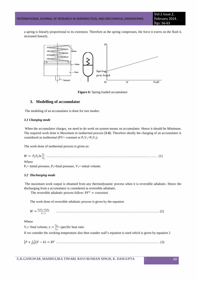
2.3 Spring loaded accumulator
A spring type accumulator is similar in operation to the gas-charged accumulator above, except that a heavy spring (or springs) is used to provide the compressive force. According to Hooke's law the magnitude of the force exerted by
INTERNATIONAL JOURNAL OF RESEARCH IN AERONAUTICAL AND MECHANICAL ENGINEERING
Vol.2 Issue.2,
February 2014.
Pgs: 56-63
G.K.GANGWAR, MADHULIKA TIWARI, RAVI BUSHAN SINGH, K. DASGUPTA 60
a spring is linearly proportional to its extension. Therefore as the spring compresses, the force it exerts on the fluid is increased linearly.
Figure 6: Spring loaded accumulator
3. Modelling of accumulator
The modeling of an accumulator is done for two modes: 3.1 Charging mode When the accumulator charges, we need to do work on system means on accumulator. Hence it should be Minimum. The required work done is Maximum in isothermal process [5-6]. Therefore ideally the charging of an accumulator is considered as isothermal (PV= constant or P1V1=P2V2). The work done of isothermal process is given as:
� �������
� ………………………………………………………………………………… …… (1)
Where P1= initial pressure, P2=final pressure, V1= initial volume. 3.2 Discharging mode
The maximum work output is obtained from any thermodynamic process when it is reversible adiabatic. Hence the discharging from a accumulator is considered as reversible adiabatic.
The reversible adiabatic process follow: P�� � �������. The work done of reversible adiabatic process is given by the equation
� � ��������
………………………………………………………………………………… (2)
Where
V2= final volume, � ���
��= specific heat ratio
If we consider the working temperature also then wander wall’s equation is used which is given by equation 2
�� � ������ � � � !" ………………………………………………………………………………… (3)

INTERNATIONAL JOURNAL OF RESEARCH IN AERONAUTICAL AND MECHANICAL ENGINEERING
Vol.2 Issue.2,
February 2014.
Pgs: 56-63
G.K.GANGWAR, MADHULIKA TIWARI, RAVI BUSHAN SINGH, K. DASGUPTA 61
4. Applications
The main applications of hydraulic accumulators are 4.1. Pressure surge damping 4.2 Emergency power source 4.3 Energy saving devices
4.1 Pressure surge damping Sudden closure of a valve causes pressure transients or shock waves. In a water system this phenomenon is called ‘water hammer’.Pressure generated by sudden closure of valve is given by ∆� � $%∆� ………………………………………………………………………………………….. ……. (4)
Where ∆� = pressure rise,
$= fluid density, C= velocity of sound
Figure7: Reduction of pressure surge
4.2 Emergency power source Hydraulic energy can be stored in an accumulator and in the event of pump failure, drawn on to operate an actuator or complete an operation. 4.3 Energy saving devices Hydraulic hybrid systems using high-pressure hydraulic accumulators have been considered as promising solutions for vehicles for the following reasons [7-8]. The high specific power of the system allows the design of compact systems. Hydraulic control systems are a mature technology. However, the specific energy of a hydraulic accumulator, which is about 6 kJ/kg, is significantly lower than that of other energy storage systems.

INTERNATIONAL JOURNAL OF RESEARCH IN AERONAUTICAL AND MECHANICAL ENGINEERING
Vol.2 Issue.2,
February 2014.
Pgs: 56-63
G.K.GANGWAR, MADHULIKA TIWARI, RAVI BUSHAN SINGH, K. DASGUPTA 62
Figure8: Example of hydraulic accumulator as energy saving device
5. Conclusion
With the above study we know the main characteristic of many kinds of accumulator which are used in current era. This study discuss where, which type of accumulator should be used. The accumulator can be used as energy supply device, energy storage device, pressure surge device, energy saving device. Instead of these it has also many applications in hydraulic field. The given example shows the energy saving up to 48% in one round of a vehicle.
References [1] ‘’Fluid Mechanics and Hydraulic Machines’’ By R.K. Bansal Laxmi Publication (p) Ltd ninth edition 2009. [2] “Power Hydraulics by Michael J. Pinches and Jhon G. Ashby” Automation advisory services, faculty of technology, Sheffield city polytechnic, UK [3] http://www.valvehydraulic.info/hydraulic-accessories/weight-loaded-type-hydraulic accumulators.html [4] http://www.dta.eu/hydraulics/hydraulic-accumulators [5]Themal Engineering by R.K. Rajput Laxmi Publication (p) Ltd sixth edition 2006. [6]Engineering Thermodynamics by P.K. Nag, The McGraw-Hill Companies Fourth Edition 2009. [7]Triet H.H. and K. K. Ahn “Comparison and assessment of a hydraulic energy saving system for hydrostatic drives” Journal of Systems and Control Engineering; Sage Publication: DOI: 10.1243/09596518JSCE1055, 5 August 2010. [8]Triet H.H and K K Ahn “Design and control of a closed-loop hydraulic energy-regenerative system” Automation in Construction 22 (2012) 444–458.
A Brief Author Biography G. K Gangwar- I am a student of M.Tech in ISM, Dhanbad. I have completed my B.Tech in Mechanical Engineering in 2012 from FGIET, Raebareli, Uttar Pradesh, India. My interested topics are strength of material, basic thermodynamics and fluid power system. Madhulika Tiwari –She is brilliant student form childhood. She has completed Diploma in Mechanical Engineering in 2008 from IERT-Allahabad, and B.Tech in Mechanical Engineering in 2012 from FGIET, Rae Bareli, Uttar-Pradesh, India.

INTERNATIONAL JOURNAL OF RESEARCH IN AERONAUTICAL AND MECHANICAL ENGINEERING
Vol.2 Issue.2,
February 2014.
Pgs: 56-63
G.K.GANGWAR, MADHULIKA TIWARI, RAVI BUSHAN SINGH, K. DASGUPTA 63
Now she is lecturer in LDC Institute of Technical studies, Allahabad. Her interested topics are strength of material, Engineering drawing and fluid power system (fluid machinery).
Ravi Bushan Singh- He is very wise person. He completed his B.Tech in mechanical engineering from Gandhi Institute of Engineering and Technology in 2012, Orissa. Now he is a student of M.Tech in ISM, Dhanbad. His research field is fluid power system and machine design.
K. Dasgupta-He is the head of the department of mechanical and mining machinery engineering; He has done his Ph.D from IIT Kharagpur in 1996. His research interest is in fluid power design and development.
.
Copyright © 2022 FDOKUMEN