STRONG-WALL® Shearwalls | ppe.cl
100
C-L-SW17 ©2017 SIMPSON STRONG-TIE COMPANY INC. 1 STRONG-WALL ® Shearwalls C-L-SW17
-
Upload
khangminh22 -
Category
Documents
-
view
0 -
download
0
Transcript of STRONG-WALL® Shearwalls | ppe.cl

C-L
-SW
17 ©
2017
SIM
PS
ON
STR
ON
G-T
IE C
OM
PAN
Y IN
C.
1
STRONG-WALL®
Shearwalls
C-L-SW17

C-L
-SW
17 ©
2017
SIM
PS
ON
STR
ON
G-T
IE C
OM
PAN
Y IN
C.
2
and Product InnovationDesign Flexibility

3
Every jobsite presents its own variety of parameters and requirements. Strong-Wall® shearwalls from Simpson Strong-Tie provide a system-oriented approach to building design that offers enhanced design flexibility and greater lateral-force resistance. With unsurpassed testing capabilities and field experience, our factory-built shearwalls maintain the industry’s highest quality standards and meet code requirements for ICC-ES, City of Los Angeles and the State of Florida.
Table of ContentsIntroduction. . . . . . . . . . . . . . . . . . . . . . . . . . . . . . . . . . . . . . . . 4
What’s New. . . . . . . . . . . . . . . . . . . . . . . . . . . . . . . . . . . . . . . . 5
Important Information and General Notes . . . . . . . . . . . . . . . . . 6
Steel Strong-Wall® 9 Standard Application on Concrete Foundations . . . . . . . . . . . 10
Anchor Tension Equations. . . . . . . . . . . . . . . . . . . . . . . . . . . . 15
Garage Portal Systems on Concrete Foundations . . . . . . . . . 16
Alternate Garage Front Options. . . . . . . . . . . . . . . . . . . . . . . . 17
First-Story Wood Floor Systems . . . . . . . . . . . . . . . . . . . . . . . 18
Balloon Framing on Concrete Foundations . . . . . . . . . . . . . . . 20
Cumulative Overturning. . . . . . . . . . . . . . . . . . . . . . . . . . . . . . 23
Two-Story Stacked on Concrete Foundations. . . . . . . . . . . . . 25
Cold-Formed Steel on Concrete Foundations. . . . . . . . . . . . . 28
Anchorage Solutions. . . . . . . . . . . . . . . . . . . . . . . . . . . . . . . . 29
Anchor Reinforcement Solutions on Grade Beams . . . . . . . . . 34
Anchor Bolt Templates . . . . . . . . . . . . . . . . . . . . . . . . . . . . . . 35
Strong-Wall® Wood Shearwall 36Applications . . . . . . . . . . . . . . . . . . . . . . . . . . . . . . . . . . . . . . 37
Product and Kit Description . . . . . . . . . . . . . . . . . . . . . . . . . . 38
Standard and Balloon Framing on Concrete Foundations. . . . 40
Garage Portal Systems on Concrete Foundations . . . . . . . . . 45
Two-Story Stacked on Concrete Foundations. . . . . . . . . . . . . 48
Anchorage Solutions. . . . . . . . . . . . . . . . . . . . . . . . . . . . . . . . 52
Anchor Reinforcement Solutions on Grade Beams . . . . . . . . . 58
Anchor Bolt Templates . . . . . . . . . . . . . . . . . . . . . . . . . . . . . . 59
Anchorage and Installation Details 60Steel Strong-Wall . . . . . . . . . . . . . . . . . . . . . . . . . . . . . . . . . . 61
Strong-Wall Wood Shearwall . . . . . . . . . . . . . . . . . . . . . . . . . 77
Steel Strong-Wall
Product Identification KeyProducts are divided into three general categories, identified by tabs along the page’s outer edge.
9—35
Strong-Wall Wood Shearwall
Anchorage and Installation Details
36—59
60—93

C-L
-SW
17 ©
2017
SIM
PS
ON
STR
ON
G-T
IE C
OM
PAN
Y IN
C.
4
Strong-Wall® Shearwalls
Introduction
Simpson Strong-Tie® Quality PolicyWe help people build safer structures economically. We do this by designing, engineering and manufacturing No-Equal structural connectors and other related products that meet or exceed our customers’ needs and expectations. Everyone is responsible for product quality and is committed to ensuring the effectiveness of the Quality Management System.
Getting Fast Technical Support When you call for engineering technical support, we can help you quickly if you have the following information at hand. This will help us to serve you promptly and efficiently.
• Which Simpson Strong-Tie catalog are you using? (See the front cover for the catalog number)
• Which Simpson Strong-Tie product are you using?
• What is your application?
• What is your load requirement?
• What is your design code and building jurisdiction?
• Is your stucture residential or commercial?
Karen ColoniasChief Executive Officer
We Are ISO 9001-2008 Registered Simpson Strong-Tie is an ISO 9001-2008 registered company. ISO 9001-2008 is an internationally-recognized quality assurance system which lets our domestic and international customers know that they can count on the consistent quality of Simpson Strong-Tie® products and services.
(800) 999-5099 | strongtie.comAll rights reserved. This catalog may not be reproduced in whole or in part without the prior written approval of Simpson Strong-Tie Company Inc.
For more than 60 years, Simpson Strong-Tie has focused on creating structural products that help people build safer and stronger homes and buildings. A leader in structural systems research and technology, Simpson Strong Tie is one of the largest suppliers of structural building products in the world. The Simpson Strong-Tie commitment to product development, engineering, testing and training is evident in the consistent quality and delivery of its products and services.
For more information, visit the company’s website at strongtie.com.
The Simpson Strong-Tie Company Inc. No-Equal Pledge® includes:
• Quality products value-engineered for the lowest installed cost at the highest-rated performance levels
• The most thoroughly tested and evaluated products in the industry
• Strategically located manufacturing and warehouse facilities
• National code agency listings
• The largest number of patented connectors in the industry
• Global locations with an international sales team
• In-house R&D and tool and die professionals
• In-house product testing and quality control engineers
• Support of industry groups including AISI, AITC, ASTM, ASCE, AWC, AWPA, ACI, AISC, CSI, CFSEI, ICFA, NBMDA, NLBMDA, SDI, SETMA, SFA, SFIA, STAFDA, SREA, NFBA, TPI, WDSC, WIJMA, WTCA and local engineering groups
Maple Ridge, BC
Kent, WA
Stockton, CAPleasanton, CA
Eagan, MN
Columbus, OH
Kansas City, KS
Gallatin, TN
Jacksonville, FL
High Point, NC
Jessup, MD
Enfield, CT
Riverside, CA
Chandler, AZ
McKinney, TX
Houston, TX
Canada Northwest Northeast Southwest Southeast
Brampton, ON
Addison, ILW. Chicago, IL
C-L
-SW
17 ©
2017
SIM
PS
ON
STR
ON
G-T
IE C
OM
PAN
Y IN
C.
5
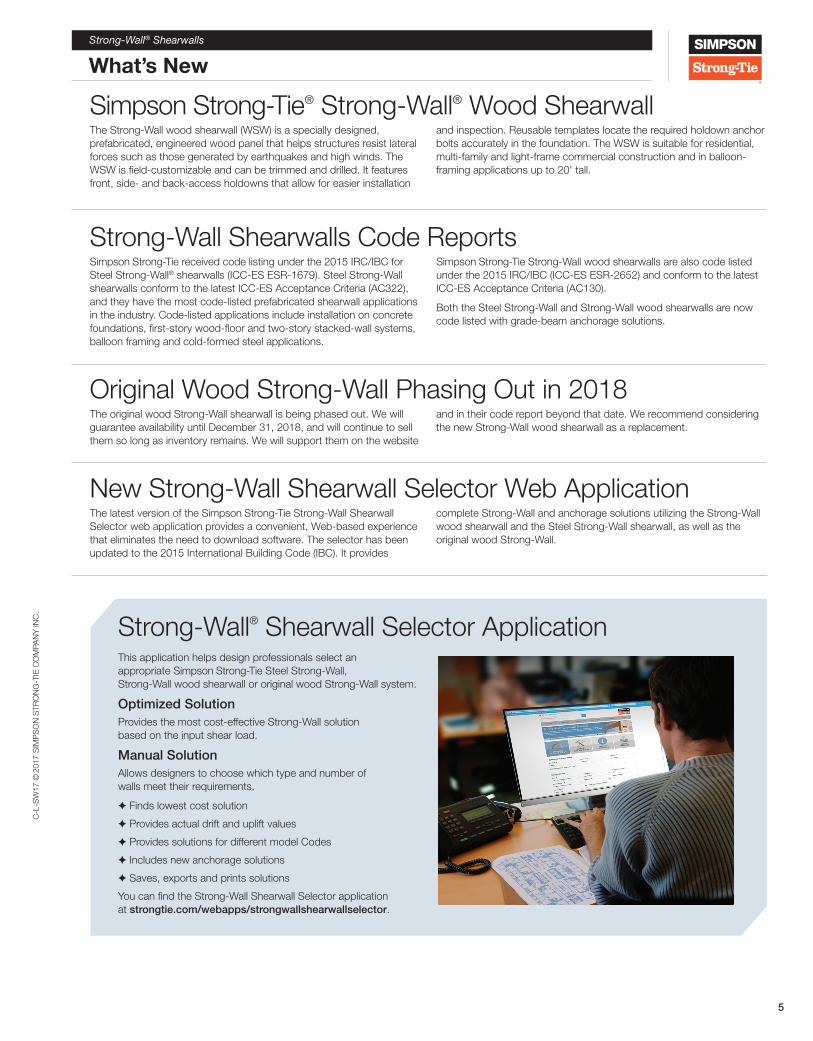
Simpson Strong-Tie® Strong-Wall® Wood ShearwallThe Strong-Wall wood shearwall (WSW) is a specially designed, prefabricated, engineered wood panel that helps structures resist lateral forces such as those generated by earthquakes and high winds. The WSW is field-customizable and can be trimmed and drilled. It features front, side- and back-access holdowns that allow for easier installation
and inspection. Reusable templates locate the required holdown anchor bolts accurately in the foundation. The WSW is suitable for residential, multi-family and light-frame commercial construction and in balloon-framing applications up to 20' tall.
Strong-Wall Shearwalls Code ReportsSimpson Strong-Tie received code listing under the 2015 IRC/IBC for Steel Strong-Wall® shearwalls (ICC-ES ESR-1679). Steel Strong-Wall shearwalls conform to the latest ICC-ES Acceptance Criteria (AC322), and they have the most code-listed prefabricated shearwall applications in the industry. Code-listed applications include installation on concrete foundations, first-story wood-floor and two-story stacked-wall systems, balloon framing and cold-formed steel applications.
Simpson Strong-Tie Strong-Wall wood shearwalls are also code listed under the 2015 IRC/IBC (ICC-ES ESR-2652) and conform to the latest ICC-ES Acceptance Criteria (AC130).
Both the Steel Strong-Wall and Strong-Wall wood shearwalls are now code listed with grade-beam anchorage solutions.
Original Wood Strong-Wall Phasing Out in 2018The original wood Strong-Wall shearwall is being phased out. We will guarantee availability until December 31, 2018, and will continue to sell them so long as inventory remains. We will support them on the website
and in their code report beyond that date. We recommend considering the new Strong-Wall wood shearwall as a replacement.
New Strong-Wall Shearwall Selector Web ApplicationThe latest version of the Simpson Strong-Tie Strong-Wall Shearwall Selector web application provides a convenient, Web-based experience that eliminates the need to download software. The selector has been updated to the 2015 International Building Code (IBC). It provides
complete Strong-Wall and anchorage solutions utilizing the Strong-Wall wood shearwall and the Steel Strong-Wall shearwall, as well as the original wood Strong-Wall.
Strong-Wall® Shearwalls
What’s New
Strong-Wall® Shearwall Selector ApplicationThis application helps design professionals select an appropriate Simpson Strong-Tie Steel Strong-Wall, Strong-Wall wood shearwall or original wood Strong-Wall system.
Optimized SolutionProvides the most cost-effective Strong-Wall solution based on the input shear load.
Manual SolutionAllows designers to choose which type and number of walls meet their requirements.
✦ Finds lowest cost solution
✦ Provides actual drift and uplift values
✦ Provides solutions for different model Codes
✦ Includes new anchorage solutions
✦ Saves, exports and prints solutions
You can find the Strong-Wall Shearwall Selector application at strongtie.com/webapps/strongwallshearwallselector.

C-L
-SW
17 ©
2017
SIM
PS
ON
STR
ON
G-T
IE C
OM
PAN
Y IN
C.
6
Strong-Wall® Shearwalls
Important Information and General Notes
WarningSimpson Strong-Tie Company Inc. structural connectors, anchors, and other products are designed and tested to provide specified design loads. To obtain optimal performance from Simpson Strong-Tie Company Inc. products and achieve maximum allowable design load, the products must be properly installed and used in accordance with the installation instructions and design limits provided by Simpson Strong-Tie Company Inc. To ensure proper installation and use, designers and installers must carefully read the following General Notes, General Instructions For The Installer and General Instructions For The Designer, as well as consult the applicable catalog pages for specific product installation instructions and notes.
Proper product installation requires careful attention to all notes and instructions, including these basic rules:
1. Be familiar with the application and correct use of the product.
2. Follow all installation instructions provided in the applicable catalog, website, Installer’s Pocket Guide or any other Simpson Strong-Tie publications.
3. Install all required fasteners per installation instructions provided by Simpson Strong-Tie Company Inc.: a) use proper fastener type; b) use proper fastener quantity; c) fill all fastener holes; d) do not overdrive or underdrive nails, including when using gun nailers; and e) ensure screws are completely driven.
4. Only bend products that are specifically designed to be bent. For those products that require bending, do not bend more than once.
In addition to following the basic rules provided above as well as all notes, warnings and instructions provided in the catalog, installers, designers, engineers and consumers should consult the Simpson Strong-Tie Company Inc. website at www.strongtie.com to obtain
additional design and installation information, including:
• Instructional builder/contractor training kits containing an instructional video, an instructor guide and a student guide in both English and Spanish;
• Information on workshops Simpson Strong-Tie conducts at various training centers throughout the country;
• Product specific installation videos;
• Specialty catalogs;
• Code reports;
• Technical fliers and bulletins;
• Engineering letters;
• Master format specifications;
• Material safety data sheets;
• Corrosion information;
• Simpson Strong-Tie Autocad menu;
• Simpson Strong-Tie Strong-Wall® Selector web application; and
• Answers to frequently asked questions and technical topics.
Failure to fully follow all of the notes and instructions provided by Simpson Strong-Tie Company Inc. may result in improper installation of products. Improperly installed products may not perform to the specifications set forth in this catalog and may reduce a structure’s ability to resist the movement, stress, and loading that occurs from gravity loads as well as impact events such as earthquakes and high velocity winds.
Simpson Strong-Tie Company Inc. does not guarantee the performance or safety of products that are modified, improperly installed or not used in accordance with the design and load limits set forth in this catalog.
General NotesThese general notes are provided to ensure proper installation of Simpson Strong-Tie Company Inc. products and must be followed fully.a. Simpson Strong-Tie Company Inc. reserves the right to change
specifications, designs and models without notice or liability for such changes.
b. Steel used for each Simpson Strong-Tie® product is individually selected based on the product’s steel specifications, including strength, thickness, formability, finish and weldability. Contact Simpson Strong-Tie for steel information on specific products.
c. Unless otherwise noted, dimensions are in inches, loads are in pounds.
d. Unless otherwise noted, welds, screws, bolts and nails may not be combined to achieve highest load value. 8d (0.131" x 2 1⁄2"), 10d (0.148" x 3") and 16d (0.162" x 3 1⁄2") specify common nails that meet the requirements of ASTM F1667. When a shorter nail is specified, it will be noted (for example 8d x 1 1⁄2"). Refer to Simpson Strong-Tie Nailing Guide, NDS (National Design Specification) and ASTM F1667 (American Society of Testing and Materials) for more nail info.
e. Do not overload. Do not exceed catalog allowable loads, which would jeopardize the connection.
f. Unless otherwise noted, allowable loads are for Douglas Fir-Larch under continuously dry conditions. Allowable loads for other species or conditions must be adjusted according to the code. The section from the AC13 criteria indicating the range of specific gravity reads as follows: 3.2.3 The species of lumber used shall have a specific
gravity not greater than 0.55 as determined in accordance with the NDS. This chart shows specific gravity and perpendicular-to-grain compression capacities for the different wood species:
Douglas Fir-Larch (DF) 625 psi 0.50
Southern Pine (SP) 565 psi 0.55
Spruce-Pine-Fir (SPF) 425 psi 0.42
Hem Fir (HF) 405 psi 0.43
Glulam 650 psi 0.50
LVL (DF/SP) 750 psi 0.50
LSL (E = 1.3 x 10⁶) 680 psi 0.50
LSL (E ≥ 1.5 x 10⁶) 880 psi 0.50
Parallam® PSL 750 psi 0.50
g. All references to bolts or machine bolts (MBs) are for structural quality through bolts (not lag screws or carriage bolts) equal to or better than ASTM Standard A307, Grade A.
h. Unless otherwise noted, bending steel in the field may cause fractures at the bend line. Fractured steel will not carry load and must be replaced.
i. A fastener that splits the wood will not take the design load. Evaluate splits to determine if the connection will perform as required. Dry wood may split more easily and should be evaluated as required. If wood tends to split, consider pre-boring holes

C-L
-SW
17 ©
2017
SIM
PS
ON
STR
ON
G-T
IE C
OM
PAN
Y IN
C.
7
Strong-Wall® Shearwalls
Important Information and General Notes
General Instructions for the InstallerThese general instructions for the installer are provided to ensure proper selection and installation of Simpson Strong-Tie Company Inc. products and must be followed carefully. These general instructions are in addition to the specific installation instructions and notes provided for each particular product, all of which should be consulted prior to and during installation of Simpson Strong-Tie Company Inc. products.
a. All specified fasteners must be installed according to the instructions in this catalog. Incorrect fastener quantity, size, placement, type, material, or finish may cause the connection to fail. Prior to using a particular fastener, please consult the Fastener Guide in this catalog.
• 16d fasteners are common nails (0.162" dia. x 3 1⁄2" long) and cannot be replaced with 16d sinkers (0.148" dia. x 3 1⁄4" long) for full load value unless otherwise specified.
• Unless otherwise noted screws may not be used to replace nails in connectors unless approved and recommended by the Designer/Engineer of Record. Unless stated otherwise, Simpson Strong-Tie cannot and does not make any representations regarding the suitability of use or load-carrying capacities of connectors with screws replacing nails.
• When using stainless-steel connectors, use stainless-steel fasteners. When using ZMAX®/HDG galvanized connectors, use fasteners that meet the zinc coating specifications of ASTM A153 or other fasteners allowed in this catalog.
b. Fill all fastener holes as specified in the installation instructions for that product.
c. Do not overdrive nails. Overdriven nails reduce shear capacity.
d. Use the materials specified in the installation instructions. Substitution of or failure to use specified materials may cause the connection to fail.
e. Do not add fastener holes or otherwise modify Simpson Strong-Tie Company Inc. products. The performance of modified products may be substantially weakened. Simpson Strong-Tie will not warrant or guarantee the performance of such modified products.
f. Install products in the position specified in the catalog.
g. Do not alter installation procedures from those set forth in this catalog.
h. Bolt holes shall be at least a minimum of 1⁄32" and no more than a maximum of 1⁄16" larger than the bolt diameter (per the 2015 NDS, Section 12.1.3.2 and AISI S100-12, Table E3 if applicable).
i. Install all specified fasteners before loading the shearwall.
j. Some hardened fasteners may have premature failure if exposed to moisture. These fasteners are recommended to be used in dry interior applications.
k. Use proper safety equipment.
l. Welding galvanized steel may produce harmful fumes; follow proper welding procedures and safety precautions. Welding should be in accordance with A.W.S. (American Welding Society) standards. Unless otherwise noted Simpson Strong-Tie® connectors cannot be welded.
m. Pneumatic or powder-actuated fasteners may deflect and injure the operator or others. Pneumatic nail tools may be used to install connectors, provided the correct quantity and type of nails (length and diameter) are properly installed in the nail holes. Tools with nail hole-locating mechanisms should be used. Follow the manufacturer’s instructions and use the appropriate safety equipment. Overdriving nails may reduce allowable loads. Contact Simpson Strong-Tie. Powder-actuated fasteners should not be used to install connectors, unless noted otherwise.
n. For cold-formed steel applications, all screws shall be installed in accordance with the screw manufacturer’s recommendations. All screws shall penetrate and protrude through the joined materials a minimum of 3 full exposed threads per AISI Standard for Cold Formed Steel Framing — General Provisions, Section D1.3, if applicable.
o. Nuts shall be installed such that the end of the threaded rod or bolt is at least flush with the top of the nut.
p. To achieve tabulated values for embedded concrete/masonry products, full consolidation of concrete or grout is required.
q. Drilling, sawing, sanding or machining wood products generates wood dust, a substance known to the State of California to cause cancer. For more information on Proposition 65, visit www.oehha.ca.gov.
r. For additional installation information, visit the Simpson Strong-Tie page at www.youtube.com/strongtie.
with diameters not exceeding 0.75 of the nail diameter (2015 NDS 12.1.5.3). Use a 5⁄32" bit for Strong-Drive® SDS Heavy-Duty Connector screws and a 3⁄32" bit for Strong-Drive SD9/SD10 Connector screws.
j. Wood shrinks and expands as it loses and gains moisture, particularly perpendicular to its grain. Take wood shrinkage into account when designing and installing connections. Simpson Strong-Tie manufactures products to fit common dry lumber dimensions. If you need a connector with dimensions other than those listed in this catalog, Simpson Strong-Tie may be able to vary connector dimensions; contact Simpson Strong-Tie. The effects of wood shrinkage are increased in multiple lumber connections, such as floor-to-floor installations. This may result in the vertical rod nuts becoming loose, requiring post-installation tightening. (Contact Simpson Strong-Tie for information on Takeup Devices.)
k. Built-up lumber (multiple members) must be fastened together to act as one unit to resist the applied load (excluding the connector fasteners). This must be determined by the Designer.
l. Some model configurations may differ from those shown in this catalog. Contact Simpson Strong-Tie for details.
m. Do not weld products listed in this catalog unless this publication specifically identifies a product as acceptable for welding, or unless specific approval for welding is provided in writing by Simpson Strong-Tie. Some steels have poor weldability and a tendency to crack when welded. Cracked steel will not carry load and must be replaced.
C-L
-SW
17 ©
2017
SIM
PS
ON
STR
ON
G-T
IE C
OM
PAN
Y IN
C.
8
Strong-Wall® Shearwalls
Important Information and General Notes
Limited WarrantySimpson Strong-Tie Company Inc. warrants catalog products to be free from defects in material or manufacturing. Simpson Strong-Tie Company Inc. products are further warranted for adequacy of design when used in accordance with design limits in this catalog and when properly specified, installed and maintained. This warranty does not apply to uses not in compliance with specific applications and installations set forth in this catalog, or to non-catalog or modified products, or to deterioration due to environmental conditions.
Simpson Strong-Tie® connectors are designed to enable structures to resist the movement, stress and loading that results from impact events such as earthquakes and high-velocity winds. Other Simpson Strong-Tie products are designed to the load capacities and uses listed in this catalog. Properly-installed Simpson Strong-Tie products will perform in accordance with the specifications set forth in the applicable Simpson Strong-Tie catalog. Additional performance limitations for specific products may be listed on the applicable catalog pages.
Due to the particular characteristics of potential impact events, the specific design and location of the structure, the building
materials used, the quality of construction, and the condition of the soils involved, damage may nonetheless result to a structure and its contents even if the loads resulting from the impact event do not exceed Simpson Strong-Tie catalog specifications and Simpson Strong-Tie connectors are properly installed in accordance with applicable building codes.
All warranty obligations of Simpson Strong-Tie Company Inc. shall be limited, at the discretion of Simpson Strong-Tie Company Inc., to repair or replacement of the defective part. These remedies shall constitute Simpson Strong-Tie Company Inc.’s sole obligation and sole remedy of purchaser under this warranty. In no event will Simpson Strong-Tie Company Inc. be responsible for incidental, consequential, or special loss or damage, however caused.
This warranty is expressly in lieu of all other warranties, expressed or implied, including warranties of merchantability or fitness for a particular purpose, all such other warranties being hereby expressly excluded. This warranty may change periodically — consult our website strongtie.com for current information.
Terms and Conditions of SaleProduct UseProducts in this catalog are designed and manufactured for the specific purposes shown, and should not be used with other connectors not approved by a qualified Designer. Modifications to products or changes in installations should only be made by a qualified Designer. The performance of such modified products or altered installations is the sole responsibility of the Designer.
IndemnityCustomers or Designers modifying products or installations, or designing non-catalog products for fabrication by Simpson Strong-Tie Company Inc. shall, regardless of specific instructions to the user, indemnify, defend and hold harmless Simpson Strong-Tie Company Inc. for any and all claimed loss or damage occasioned in whole or in part by non-catalog or modified products.
Non-Catalog and Modified ProductsConsult Simpson Strong-Tie Company Inc. for applications for which there is no catalog product, or for connectors for use in hostile environments, with excessive wood shrinkage, or with abnormal loading or erection requirements.
Non-catalog products must be designed by the customer and will be fabricated by Simpson Strong-Tie in accordance with customer specifications.
Simpson Strong-Tie cannot and does not make any representations regarding the suitability of use or load-carrying capacities of non-catalog products. Simpson Strong-Tie provides no warranty, express or implied, on non-catalog products.
General Instructions for the DesignerThese general instructions for the designer are provided to ensure proper selection and installation of Simpson Strong-Tie Company Inc. products and must be followed carefully. These general instructions are in addition to the specific design and installation instructions and notes provided for each particular product, all of which should be consulted prior to and during the design process.
a. The term “Designer” used throughout this catalog is intended to mean a licensed/certified building design professional, a licensed professional engineer, or a licensed architect.
b. All connected members and related elements shall be designed by the Designer.
c. All installations should be designed only in accordance with the allowable load values set forth in this catalog.
d. Simpson Strong-Tie strongly recommends the following addition to construction drawings and specifications: “Simpson Strong-Tie® products are specifically required to meet the structural calculations of plan. Before substituting another brand, confirm load capacity based on reliable published testing data or calculations. The Engineer/Designer of Record should evaluate and give written approval for substitution prior to installation.”
e. For cold-formed steel applications, as a minimum all screws must comply with Society of Automotive Engineers (SAE) Standard J78, Steel Self-Drilling/Tapping Screws, and must have a Type II coating in accordance with ASTM B 633, Electrodeposited Coatings of Zinc on Iron and Steel. Screw strength shall be calculated in accordance with AISI S100-12 Section E4, if applicable, or shall be based on the manufacturer’s design capacity determined from testing.
f. Local and/or regional building codes may require meeting special conditions. Building codes often require special inspection of anchors installed in concrete and masonry. For compliance with these requirements, it is necessary to contact the local and/or regional building authority. Except where mandated by code, Simpson Strong-Tie products do not require special inspection.
g. For Masterformat® specifications, visit www.strongtie.com/literature/masterformat.html.

Ste
el S
tron
g-W
all®
C-L
-SW
17 ©
2017
SIM
PS
ON
STR
ON
G-T
IE C
OM
PAN
Y IN
C.
9
Steel Strong-Wall®
Working with specifiers, builders and contractors has given Simpson Strong-Tie insight into the needs of the various players in the design and construction process. This insight has enabled Simpson Strong-Tie to design a composite shearwall that features some of the highest allowable loads in the industry while offering the easiest and fastest installation: The Steel Strong-Wall® shearwall.
• Code Listed — New ICC-ES ESR-1679, City of L.A. RR 25625 and State of Florida FL 5113 code reports evaluated to the 2015 IRC/IBC
• Less Labor = Increased Production — Fewer anchor bolts and fasteners coupled with easy access to the top and bottom of the wall result in more efficient installation
• Easier for All Trades — An easy-to-use anchor-bolt template for concrete contractors, preattached wood studs and predrilled holes where electricians need them for wiring
• Support and Service — Simpson Strong-Tie provides the best engineering technical support and experienced field representation available
The Steel Strong-Wall product line has grown to address more applications:
• Standard installations on concrete
• Garage portal system
• Anchorage solutions
• Wood floor solutions
• Two-story stacked shearwalls
• Balloon framing up to 20' tall
• Cold-formed steel applications

Ste
el S
tron
g-W
all®
C-L
-SW
17 ©
2017
SIM
PS
ON
STR
ON
G-T
IE C
OM
PAN
Y IN
C.
10
Standard Application on Concrete FoundationsSimpson Strong-Tie® Steel Strong-Wall® shearwalls provide superior performance, design flexibility and ease of installation. All Steel Strong-Wall shearwalls are evaluated to the 2015 IRC/IBC and are listed by ICC-ES.
Material: Vertical Panel—10 gauge
Finish: Vertical Panel—Galvanized Top and Base Plates—Simpson Strong-Tie® gray paintCodes: ICC-ES ESR-1679; City of L.A. RR 25625; State of Florida FL5113
SSW24x8
Steel Strong-WallWidth(in.)
Nominal Height(ft.)
Naming Legend
Wall Profiles
SSW15
SSW18
SSW21
SSW12
SSW15
SSW18
SSW21
SSW24 SSW24
Standard InstallationU.S. Patent 8,281,551
Canadian Patent 2,489,845
Attaches easily to header or top plates.
Attach optional blocking or framing
using extra 1⁄4" holes
Additional openings for plumbing
Predrilled holes with grommets for wiring
and electrical
Preattached wood studs for easier integration into
framing
Anchors with only two bolts –
form-mounted templates allow
precise placement before the pour
SSW24x10
Garage InstallationU.S. Patent 8,281,551
Canadian Patent 2,489,845
SSW12x7
Additional 1 1/8"diameter holesallowed in woodstud at eachobround hole
Foundation design(size and reinforcement) by Designer
See page 17 for garage-wall options based on standard installation and page 16 for higher capacity garage portal system
Steel Strong-Wall® Shearwalls
Preattached wood studs are 2x4 for walls 7'-10' tall, and 2x6 for walls 11'-13' tall.
12"
15"

Ste
el S
tron
g-W
all®
C-L
-SW
17 ©
2017
SIM
PS
ON
STR
ON
G-T
IE C
OM
PAN
Y IN
C.
11
Standard Application on Concrete Foundations
Standard InstallationU.S. Patent 8,281,551
Canadian Patent 2,489,845
Installation Information • Do not cut the Steel Strong-Wall® or enlarge existing holes. Doing so will compromise the performance of the wall.
• Do not use an impact wrench to tighten nuts on the anchor bolts.
• Maximum shim thickness between the Steel Strong-Wall and top plates or header is 7/8" using Simpson Strong-Tie® Strong-Drive® 1⁄4" x 3 1⁄2" SDS Heavy-Duty Connector screws. For top of wall height adjustment, see detail 5/SSW2 on page 67.
• Walls with 2x4 preattached studs may also be used in 2x6 or 2x8 wall framing. Install the wall flush to one face of the framing and add furring to the opposite side.
• Walls may be installed with solid or multi-ply headers, see detail 11/SSW2 page 68 for details.
Steel Strong-Wall® Product Data
Model No. W (in.)
H (in.)
T (in.)
Anchor Bolts
Number of Screws
in Top of Wall
Total Wall
Weight (lb.)Qty. Dia.
(in.)SSW12x7 12 80 3½ 2 3/4 4 74SSW15x7 15 80 3½ 2 1 6 86SSW18x7 18 80 3½ 2 1 9 99SSW21x7 21 80 3½ 2 1 12 117SSW24x7 24 80 3½ 2 1 14 127
SSW12x7.4 12 85½ 3½ 2 3/4 4 78SSW15x7.4 15 85½ 3½ 2 1 6 91SSW18x7.4 18 85½ 3½ 2 1 9 104SSW21x7.4 21 85½ 3½ 2 1 12 122SSW24x7.4 24 85½ 3½ 2 1 14 134SSW12x8 12 93¼ 3½ 2 3/4 4 85SSW15x8 15 93¼ 3½ 2 1 6 99SSW18x8 18 93¼ 3½ 2 1 9 113SSW21x8 21 93¼ 3½ 2 1 12 132SSW24x8 24 93¼ 3½ 2 1 14 144SSW12x9 12 105¼ 3½ 2 3/4 4 94SSW15x9 15 105¼ 3½ 2 1 6 110SSW18x9 18 105¼ 3½ 2 1 9 125SSW21x9 21 105¼ 3½ 2 1 12 147SSW24x9 24 105¼ 3½ 2 1 14 160
SSW12x10 12 117¼ 3½ 2 3/4 4 104SSW15x10 15 117¼ 3½ 2 1 6 121SSW18x10 18 117¼ 3½ 2 1 9 138SSW21x10 21 117¼ 3½ 2 1 12 162SSW24x10 24 117¼ 3½ 2 1 14 177SSW15x11 15 129¼ 5½ 2 1 6 148SSW18x11 18 129¼ 5½ 2 1 9 167SSW21x11 21 129¼ 5½ 2 1 12 193SSW24x11 24 129¼ 5½ 2 1 14 209SSW15x12 15 141¼ 5½ 2 1 6 160SSW18x12 18 141¼ 5½ 2 1 9 180SSW21x12 21 141¼ 5½ 2 1 12 208SSW24x12 24 141¼ 5½ 2 1 14 225SSW18x13 18 153¼ 5½ 2 1 9 194SSW21x13 21 153¼ 5½ 2 1 12 224SSW24x13 24 153¼ 5½ 2 1 14 243
Header Connection
(See page 68 detail 11/SSW2 for multi-ply
header option and page 16 for Garage Portal System)
DO NOT cut wall or enlarge
existing holes
Place Steel Strong-Wall shearwall over the anchor bolts and secure with heavy hex nuts (provided). Snug tight fit required, do not use an impact wrench.• 1 1/4" wrench/socket required for 3/4" nut• 1 5/8" wrench/socket required for 1" nut
Attach to top plates or header with
1⁄4" x 3 1⁄2" SDS screws (provided).
Shim as necessaryfor tight fit
T
W
H
Steel Strong-Wall® Shearwalls

Ste
el S
tron
g-W
all®
C-L
-SW
17 ©
2017
SIM
PS
ON
STR
ON
G-T
IE C
OM
PAN
Y IN
C.
12
Steel Strong-Wall® Shearwalls
Standard Application on Concrete Foundations
SSW Model
Allowable Axial Load
(lb.)
Seismic2 Wind
Allowable ASD Shear Load V
(lb.)
Drift at Allowable Shear
(in.)
Anchor Tension at Allowable Shear5
(lb.)
Allowable ASD Shear Load V
(lb.)
Drift at Allowable Shear
(in.)
Anchor Tension at Allowable Shear5
(lb.)
SSW12x71,000 955 0.36 9,840 1,215 0.46 13,6204,000 955 0.36 9,840 1,095 0.42 11,7657,500 890 0.34 9,010 890 0.34 9,010
SSW15x71,000 1,855 0.36 15,655 1,860 0.36 15,7154,000 1,665 0.33 13,550 1,665 0.33 13,5507,500 1,445 0.28 11,340 1,445 0.28 11,340
SSW18x71,000 2,905 0.34 19,660 3,480 0.41 25,8054,000 2,905 0.34 19,660 3,250 0.38 23,1357,500 2,905 0.34 19,660 2,980 0.35 20,370
SSW21x71,000 4,200 0.32 23,755 4,440 0.34 25,7104,000 4,200 0.32 23,755 4,440 0.34 25,7107,500 4,200 0.32 23,755 4,310 0.33 24,635
SSW24x71,000 5,495 0.29 26,270 5,730 0.31 27,8354,000 5,495 0.29 26,270 5,730 0.31 27,8357,500 5,495 0.29 26,270 5,730 0.31 27,835
SSW12x7.41,000 870 0.39 9,515 1,105 0.49 13,0704,000 870 0.39 9,515 970 0.43 10,9407,500 750 0.33 7,940 750 0.33 7,940
SSW15x7.41,000 1,685 0.39 15,035 1,700 0.39 15,2154,000 1,500 0.34 12,905 1,500 0.34 12,9057,500 1,270 0.29 10,510 1,270 0.29 10,510
SSW18x7.41,000 2,700 0.37 19,475 3,255 0.44 25,7904,000 2,700 0.37 19,475 3,040 0.42 23,1257,500 2,700 0.37 19,475 2,790 0.38 20,390
SSW21x7.41,000 3,890 0.35 23,420 4,230 0.38 26,4054,000 3,890 0.35 23,420 4,230 0.38 26,4057,500 3,890 0.35 23,420 4,035 0.36 24,655
SSW24x7.41,000 5,330 0.34 27,610 5,450 0.34 28,4854,000 5,330 0.34 27,610 5,450 0.34 28,4857,500 5,330 0.34 27,610 5,450 0.34 28,485
SSW12x81,000 775 0.42 9,180 985 0.53 12,5604,000 775 0.42 9,180 865 0.47 10,5507,500 665 0.36 7,630 665 0.36 7,630
SSW15x81,000 1,505 0.42 14,515 1,530 0.43 14,8354,000 1,345 0.37 12,545 1,345 0.37 12,5457,500 1,135 0.32 10,190 1,135 0.32 10,190
SSW18x81,000 2,480 0.41 19,525 2,985 0.50 25,7954,000 2,480 0.41 19,525 2,790 0.47 23,1607,500 2,480 0.41 19,525 2,560 0.43 20,410
SSW21x81,000 3,560 0.39 23,360 3,960 0.43 27,2404,000 3,560 0.39 23,360 3,960 0.43 27,2407,500 3,560 0.39 23,360 3,700 0.41 24,660
SSW24x81,000 4,865 0.37 27,435 5,105 0.39 29,3704,000 4,865 0.37 27,435 5,105 0.39 29,3707,500 4,865 0.37 27,435 5,055 0.39 28,960
SSW12x91,000 660 0.47 8,745 840 0.60 11,9154,000 660 0.47 8,745 705 0.50 9,4857,500 505 0.36 6,380 505 0.36 6,380
SSW15x91,000 1,315 0.45 14,250 1,315 0.47 14,2504,000 1,130 0.38 11,740 1,130 0.40 11,7407,500 925 0.31 9,235 925 0.33 9,235
SSW18x91,000 2,145 0.47 18,890 2,645 0.58 25,8004,000 2,145 0.47 18,890 2,470 0.54 23,1307,500 2,145 0.47 18,890 2,265 0.50 20,370
SSW21x91,000 3,145 0.46 23,265 3,590 0.52 28,2154,000 3,145 0.46 23,265 3,530 0.51 27,4907,500 3,145 0.46 23,265 3,280 0.47 24,680
SSW24x91,000 4,285 0.44 27,210 4,605 0.47 30,1504,000 4,285 0.44 27,210 4,605 0.47 30,1507,500 4,285 0.44 27,210 4,480 0.46 28,970
See footnotes on page 13.

Ste
el S
tron
g-W
all®
C-L
-SW
17 ©
2017
SIM
PS
ON
STR
ON
G-T
IE C
OM
PAN
Y IN
C.
13
Steel Strong-Wall® Shearwalls
Standard Application on Concrete Foundations
SSW Model
Allowable Axial Load
(lb.)
Seismic2 Wind
Allowable ASD Shear Load V
(lb.)
Drift at Allowable Shear
(in.)
Anchor Tension at Allowable Shear5
(lb.)
Allowable ASD Shear Load V
(lb.)
Drift at Allowable Shear
(in.)
Anchor Tension at Allowable Shear5
(lb.)
SSW12x101,000 570 0.52 8,345 725 0.67 11,3004,000 570 0.52 8,345 570 0.52 8,3457,500 360 0.33 4,930 360 0.33 4,930
SSW15x101,000 1,110 0.53 13,150 1,145 0.54 13,6904,000 960 0.45 10,975 960 0.45 10,9757,500 715 0.34 7,775 715 0.34 7,775
SSW18x101,000 1,860 0.53 18,030 2,360 0.67 25,5454,000 1,860 0.53 18,030 2,215 0.63 23,0957,500 1,860 0.53 18,030 2,035 0.57 20,395
SSW21x101,000 3,045 0.50 25,905 3,265 0.56 28,7954,000 3,045 0.50 25,905 3,170 0.54 27,5107,500 2,780 0.45 22,780 2,780 0.47 22,780
SSW24x101,000 3,835 0.50 27,100 4,205 0.55 30,9204,000 3,835 0.50 27,100 4,205 0.55 30,9207,500 3,790 0.49 26,660 3,790 0.49 26,660
SSW15x111,000 975 0.58 12,625 1,015 0.60 13,2854,000 815 0.48 10,135 815 0.48 10,1357,500 550 0.33 6,470 550 0.33 6,470
SSW18x111,000 1,635 0.58 17,295 2,075 0.73 24,2804,000 1,635 0.58 17,295 2,010 0.71 23,1107,500 1,635 0.58 17,295 1,730 0.61 18,645
SSW21x111,000 2,485 0.58 22,325 2,990 0.70 29,2304,000 2,485 0.58 22,325 2,785 0.65 26,2207,500 2,305 0.54 20,205 2,305 0.54 20,205
SSW24x111,000 3,475 0.57 27,055 3,845 0.63 31,2854,000 3,475 0.57 27,055 3,710 0.60 29,6807,500 3,205 0.52 24,260 3,205 0.52 24,260
SSW15x121,000 815 0.63 11,280 905 0.70 12,8554,000 690 0.53 9,245 690 0.53 9,2457,500 390 0.30 4,905 390 0.30 4,905
SSW18x121,000 1,450 0.63 16,605 1,845 0.80 23,2204,000 1,450 0.63 16,605 1,815 0.79 22,6507,500 1,435 0.62 16,380 1,435 0.62 16,380
SSW21x121,000 2,210 0.63 21,485 2,755 0.79 29,5554,000 2,210 0.63 21,485 2,420 0.69 24,3357,500 1,900 0.54 17,690 1,900 0.54 17,690
SSW24x121,000 3,150 0.63 26,710 3,540 0.71 31,5754,000 3,150 0.63 26,710 3,250 0.65 27,8907,500 2,705 0.54 21,855 2,705 0.54 21,855
SSW18x131,000 1,335 0.68 16,580 1,695 0.87 23,1054,000 1,335 0.68 16,580 1,580 0.81 20,8307,500 1,180 0.60 14,195 1,180 0.60 14,195
SSW21x131,000 1,985 0.68 20,765 2,520 0.87 29,2004,000 1,985 0.68 20,765 2,110 0.73 22,5307,500 1,555 0.53 15,300 1,555 0.53 15,300
SSW24x131,000 2,830 0.68 25,795 3,275 0.79 31,7554,000 2,830 0.68 25,795 2,860 0.69 26,1657,500 2,280 0.55 19,545 2,280 0.55 19,545
1. Allowable shear loads and anchor tension forces are applicable to installation on concrete with minimum f'c = 2,500 psi using the ASD basic (Section 1605.3.1) or the alternative basic (Section 1605.3.2) load combinations. Load values include evaluation of bearing stresses on the foundation and do not require further evaluation by the Designer.
2. For seismic designs based on the 2015 IBC using R = 6.5. For other codes, use the seismic coefficients corresponding to light-frame bearing walls with wood structural panels or sheet steel panels.
3. Allowable shear, drift, and anchor tension values may be interpolated for intermediate height or axial loads.
4. High-strength anchor bolts are required for anchor tension forces exceeding the allowable load for standard-strength bolts tabulated on pages 29–30. High-strength anchor bolts are required for SSW12 when the seismic overturning moment (seismic shear x shearwall height) exceeds 61,600 in.-lb. See pages 29–35 for SSWAB anchor bolt information and anchorage solutions.
5. Tabulated anchor tension loads assume no resisting axial load. For anchor tension loads at design shear values and including the effect of axial load, refer to the Strong-Wall Selector web application or use the equations on page 15. Drifts at lower design shear may be linearly reduced.
6. See page 14 for allowable out-of-plane loads and axial capacities.

Ste
el S
tron
g-W
all®
C-L
-SW
17 ©
2017
SIM
PS
ON
STR
ON
G-T
IE C
OM
PAN
Y IN
C.
14
Steel Strong-Wall® Shearwalls
Standard Application on Concrete Foundations
Allowable Out-of-Plane Loads (psf) for Single-Story Walls on Concrete Foundations
Model Width (in.)
Axial Load (lb.)
Nominal Height of Shearwall (ft.)
8 9 10 11 12 13
12
1,000 200 140 105 N/A N/A N/A
4,000 150 105 70 N/A N/A N/A
7,500 90 55 25 N/A N/A N/A
15
1,000 165 130 100 80 70 N/A
4,000 130 95 70 50 40 N/A
7,500 95 65 45 30 15 N/A
18 7,500 310 215 160 120 90 70
21 7,500 260 185 135 100 70 50
24 7,500 275 195 135 105 80 65
1. Loads shown are at ASD level in pounds per square foot (psf) of wall with no further increase in load allowed.
2. Axial load denotes maximum gravity load permitted on entire panel acting in combination with the out-of-plane load.
3. Load considers a deflection limit of h/240.4. Values are applicable to either the ASD basic or alternative basic
load combinations.
5. Allowable out-of-plane loads for the 12- and 15-inch walls may be linearly interpolated between the axial loads shown.
6. Table loads apply only to single-story walls on concrete foundations.
7. N/A =Not Applicable.
Axial Capacities for Single-Story Walls on Concrete FoundationsModel Width (in.)
Compression Capacity with No Lateral Loads (lb.)
Nominal Height of Shearwall (ft.)
7 7.4 8 9 10 11 12 13
12 20,200 19,000 17,200 14,500 11,800 N/A N/A N/A
15 25,300 24,200 22,600 20,000 17,400 14,900 12,600 N/A
18 42,500 40,400 37,500 32,900 28,400 24,100 20,200 17,200
21 43,700 41,100 37,500 32,000 26,700 22,000 18,400 15,700
24 51,600 48,800 44,800 38,700 32,900 27,400 22,900 19,500
1. Compression capacity is lesser of wall buckling capacity or 2,500 psi concrete bearing limit.
2. Compression capacity of wall assumes no lateral loads present. See allowable in-plane or out-of-plane load tables for combined lateral and axial loading conditions.
3. Values are applicable to either the ASD basic or alternative basic load combinations.
4. Table loads apply only to single-story walls on concrete foundations.
5. N/A =Not Applicable.
Allowable Tension Loads for Steel Strong-Wall® Wood Jamb StudModel Width (in.)
Tension Capacity per Jamb Stud (lb.)
Nominal Height of Shearwall (ft.)
7 7.4 8 9 10 11 12 13
12 1,535 1,535 1,845 2,150 2,500 N/A N/A N/A
15 1,845 2,150 2,460 2,500 2,500 3,070 3,685 N/A
18 1,845 1,845 2,150 2,500 2,500 3,380 3,685 3,980
21 1,845 1,845 2,150 2,500 2,500 3,070 3,685 3,980
24 1,845 1,845 2,150 2,500 2,500 3,070 3,685 3,980
1. Allowable tension load is based on capacity of the lesser of the connection between the stud and the steel shearwall or stud tension capacity. The capacity of the SSW wall anchor bolt and anchorage to the foundation must be adequate to transfer the additional tension.
2. Loads include a 1.60 load duration increase for wood subjected to wind or earthquake. Reductions for other load durations must be taken according to the applicable code.
3. N/A =Not Applicable.

Ste
el S
tron
g-W
all®
C-L
-SW
17 ©
2017
SIM
PS
ON
STR
ON
G-T
IE C
OM
PAN
Y IN
C.
15
Steel Strong-Wall® Shearwalls
Anchor Tension Equations
Calculating Anchor Tension Forces at Base of WallThese equations may be used to calculate anchor tension forces at the base of the first-story wall to aid Designers in developing anchorage solutions other than those shown on pages 29-34.
Example 1 — Single-Story SSW:Given:
• SSW18x9 wall on 2.5 ksi concrete
• Seismic Loading
• Design Shear (V) = 2.0 kips < 2.15 kips (Vallowable )
• P (Vertical Load) = 1.0 kip
• h = Wall height = 105.25"
• k = 1.0
T = Resulting anchorage tension force (kips)
V = Design shear (kips)
P = Total vertical load (kips)
h = Wall height (inches)
f’c = Concrete compressive Strength (ksi)
k = 1.0 for all applications except Garage Portal Systems
For Garage Portal Systems using the SSWP-KT Portal Kit:
k = 0.80 for SSW12
k = 0.85 for SSW15
k = 0.90 for SSW18
For two-story stacked applications,
substitute Mbase for Vh:
Vh = Mbase kip - in.
Where Mbase = Design moment at base of wall (ft.-lb.)(
12 ) 1000
Example 2 — Two-Story Stacked SSW Condition:Given:
• See Two-Story Design Example on page 28
• SSW18x9-STK wall on 2.5 ksi concrete
• Wind Loading
• Mbase = 17,550 ft-lb. (Moment at base of two-story stacked wall)
• Vh = 17,550 x kip-in = 210.6 kip-in.
• P (Vertical Load) = 2.0 kips
• k = 1.0
( 12 ) 1000
PV
hM
Moment Arm
C T
Base
Forces at Base of Wall
Notes:1. Equations may be used to calculate anchor tension forces at the
base of first-story walls on concrete foundations.2. Equations are based on the design methodology contained in AISC
Steel Design Guide 1 – Base Plate and Anchor-Rod Design, second edition using a rectangular compression stress block.
3. Equations are based on concrete bearing on a 3 1⁄2"-wide base plate at the edge of the concrete.
12 in. wall
15 in. wall
18 in. wall
21 in. wall
24 in. wall

Ste
el S
tron
g-W
all®
C-L
-SW
17 ©
2017
SIM
PS
ON
STR
ON
G-T
IE C
OM
PAN
Y IN
C.
16
Steel Strong-Wall® Shearwalls
Garage Portal Systems on Concrete FoundationsSimpson Strong-Tie offers a Steel Strong-Wall® shearwall option for garage portal systems which combines simplified installation with superior performance.
• Higher capacity with reduced concrete anchorage requirements (see Alternate Garage Front Options on page 17 for other options)
• Same anchor bolt template
• Complete kit available to simplify the connection to the header or beam
For product data and naming scheme information, see pages 10–11.
Suggested Example Specification: SSW12x7 with SSWP-KT
Garage Header Rough Opening HeightModel No. H Curb Rough
Opening Height
SSW12x7 SSW15x7 SSW18x7
5 1⁄2" 7'-1 1⁄2"
6" 7'-2"
SSW12x7.4 SSW15x7.4 SSW18x7.4
0" 7'-1 1⁄2"
SSW12x8 SSW15x8 SSW18x8
5 1⁄2" 8'-2 3/4" 3
6" 8'-3 1⁄4" 3
1. The height of the garage curb above the garage slab is critical for rough header opening at garage return walls.
2. Shims are not provided with Steel Strong-Wall®.3. Furring down garage header may be necessary for correct rough opening height.
Installation • Portal Frame Connection Kit is required to achieve increased load values listed for portal frame system.
• SSWPS straps must be installed on exterior face of the Steel Strong-Wall® shearwall. Position header flush with exterior face of the Steel Strong-Wall shearwall.
• Do not cut the Steel Strong-Wall or enlarge existing holes. Doing so will compromise the performance of the wall.
• Do not use an impact wrench to tighten nuts on the anchor bolts.
• Maximum shim thickness between the Steel Strong-Wall and header is 7/8" using Simpson Strong-Tie® Strong-Drive® 1⁄4" x 3 1⁄2" SDS Heavy-Duty Connector screws.
• Walls with 2x4 preattached studs may also be used in 2x6 wall framing. Install the wall flush to exterior face of the framing and add furring to the opposite side.
• Walls may be installed with solid or multi-ply headers, see detail 11/SSW2 page 68 for details.
Portal Frame Connection KitModel No. Contents
SSWP-KT(2) 10 gauge SSWPS straps(8) #14 x 1" self-drilling screwsInstallation instructions
For a complete set of wall profiledrawings, see page 10.
Exterior face
Shear transferby Designer
Rough openingheight Steel
Strong-Wall® panel (exterior face)
Simpson Strong-Tie®
LSTA24 strap (min.)at beam to post
See page 11 forconnection to foundation
See page 11 for header connection
Foundation design (size and reinforcement)by Designer
Header byDesigner –
3⅛" min. widthx 12" min.
nominal depth*
8' Min. 16'-4" Max.*
Simpson Strong-Tie®
SSWPS straps
HCurb
Header support post(design by Designer)
Column base detail by Designer(not shown for clarity)
Simpson Strong-Tie®
STHD10 holdown (1000 lb. uplift capacity min.)*
(10) 10dx2½"minimum nails
(4) #14 x 1"(provided with SSWP-KT)
Align notches with bottom of header
Simpson Strong-Tie®
SSWPS straps
Header
Max. ⅞" shimas required
Steel Strong-Wall®
panel
DO NOT cut wall or enlarge
existing holes
*This installation reflects lateral load requirements of a single-wall portal system. It is the Designer’s responsibility to provide a complete load path for all loads in accordance
with the governing codes. Refer to footnotes 2, 4 and 9 on page 17.
U.S. Patent8,281,551Canadian Patent2,489,845

Ste
el S
tron
g-W
all®
C-L
-SW
17 ©
2017
SIM
PS
ON
STR
ON
G-T
IE C
OM
PAN
Y IN
C.
17
Steel Strong-Wall® Shearwalls
Garage Portal Systems on Concrete Foundations
HCurb
HCurb
Garage Wall Option 1 Garage Wall Option 2
Note: Steel Strong-Wall®nominal 7 ft. height walls are80", that is 2" taller thanStrong-Wall® wood shearwalls.
See page 68, detail 11/SSW2 formulti-ply header options
U.S. Patent8,281,551Canadian Patent2,489,845
Header and postby Designer
Column base detailby Designer(not shown)
Sheartransfer byDesigner
Header byDesigner —
3⅛" min.width
HCurb
Roughopeningheight
SSW Model
Allowable Axial Load (lb.)
Single-Wall Garage Portal System2
Seismic3 Wind
Allowable ASD
Shear Load V
(lb.)
Drift at Allowable
Shear (in.)
Anchor Tension at Allowable
Shear8 (lb.)
Allowable ASD
Shear Load V
(lb.)
Drift at Allowable
Shear (in.)
Anchor Tension at Allowable
Shear8 (lb.)
SSW12x7 w/ SSWP-KT
1,000 1,350 0.42 11,550 1,645 0.51 15,3904,000 1,350 0.42 11,550 1,435 0.45 12,5607,500 1,185 0.37 9,750 1,185 0.37 9,750
SSW15x7 w/ SSWP-KT
1,000 2,210 0.38 15,930 2,210 0.38 15,9304,000 2,000 0.34 13,925 2,000 0.34 13,9257,500 1,760 0.30 11,835 1,760 0.30 11,835
SSW18x7 w/ SSWP-KT
1,000 3,865 0.40 25,785 3,865 0.40 25,7854,000 3,610 0.38 23,125 3,610 0.38 23,1257,500 3,315 0.35 20,405 3,315 0.35 20,405
SSW12x7.4 w/ SSWP-KT
1,000 1,275 0.45 11,695 1,535 0.54 15,3204,000 1,275 0.45 11,695 1,310 0.46 12,1357,500 1,045 0.37 9,055 1,045 0.37 9,055
SSW15x7.4 w/ SSWP-KT
1,000 2,065 0.42 15,900 2,065 0.42 15,9004,000 1,855 0.37 13,765 1,855 0.37 13,7657,500 1,590 0.32 11,330 1,590 0.32 11,330
SSW18x7.4 w/ SSWP-KT
1,000 3,615 0.45 25,770 3,615 0.45 25,7704,000 3,380 0.42 23,150 3,380 0.42 23,1507,500 3,100 0.38 20,390 3,100 0.38 20,390
SSW12x8 w/ SSWP-KT
1,000 1,180 0.46 11,845 1,375 0.55 14,7704,000 1,140 0.45 11,305 1,140 0.45 11,3057,500 875 0.35 8,110 875 0.35 8,110
SSW15x8 w/ SSWP-KT
1,000 1,865 0.42 15,570 1,865 0.42 15,5704,000 1,640 0.37 13,130 1,640 0.37 13,1307,500 1,380 0.31 10,600 1,380 0.31 10,600
SSW18x8 w/ SSWP-KT
1,000 3,280 0.47 25,325 3,315 0.48 25,7754,000 3,100 0.45 23,160 3,100 0.45 23,1607,500 2,840 0.41 20,365 2,840 0.41 20,365
1. Allowable shear loads and anchor tension forces are applicable to Single-Wall Garage Portal System installation on concrete with minimum f'c = 2,500 psi using the ASD basic (Section 1605.3.1) or the alternative basic (Section 1605.3.2) load combinations. Load values include evaluation of bearing stresses.
2. A Double-Wall Garage Portal System consists of two walls with a header continuous across both panels. The allowable load is twice the Single-Wall Portal value.
3. For seismic designs based on the 2015 IBC using R=6.5. For other codes, use the seismic coefficients corresponding to light-frame bearing walls with wood structural panels or sheet steel panels.
4. The minimum header size shown in the details is the minimum required for lateral rigidity of the portal system. Larger headers may be required due to vertical loading. Support post uplift connectors may be reduced where justified by calculations.
5. Recommended header moisture content is 19% or less at time of installation.
6. Allowable shear, drift and anchor tension values may be interpolated for intermediate height or axial loads.
7. High-strength anchor bolts are required for anchor tension forces exceeding the allowable load for standard-strength bolts tabulated on pages 29–30. High-strength anchor bolts are required for SSW12 when the seismic overturning moment (seismic shear x shearwall height) exceeds 61,600 in.-lb. See pages 29–35 for SSWAB anchor bolt information and anchorage solutions.
8. Tabulated anchor tension loads assume no resisting axial load. For anchor tension loads at design shear values and including the effect of axial load, refer to the Strong-Wall Selector web application or use the equations on page 15 (include K factor in uplift calculations). Drifts at lower design shear may be linearly reduced.
9. Longer header spans can be accommodated if larger headers are used such that equivalent stiffness is equal to or greater than that provided by the minimum header size and maximum length indicated.
Alternate Garage Front OptionsThese alternate garage front options may be used for applications when the Steel Strong-Wall® shearwall is installed at the full height (option 1) or without the additional Portal Frame Kit (option 2), when higher capacity or reduced concrete anchorage are not needed. Refer to the Standard Application on Concrete Foundations on pages 10–13 for product data and allowable load values.
For Garage Wall Option 2, the Designer shall design for:1. Shear transfer
2. Out-of-plane loading effect
3. Increased overturning and drift due to additional height

Ste
el S
tron
g-W
all®
C-L
-SW
17 ©
2017
SIM
PS
ON
STR
ON
G-T
IE C
OM
PAN
Y IN
C.
18
Steel Strong-Wall® Shearwalls
First-Story Wood Floor SystemsSteel Strong-Wall® shearwalls designed for use on concrete foundations can be used with wood floor systems by extending the anchor bolts and installing compression nuts and solid blocking below the wall.
Material & Finish: See page 10.
Codes: ICC-ES ESR-1679:City of L.A. RR25625;State of Florida FL5113
For product data and naming scheme information, see pages 10–13.
Wood First-Floor Wall Connection KitWall Width
(in.) Model No. Contents
12 SSW12-1KT (1) Shear-Transfer Plate (with #14 self-drilling screws)(2) 3/4" or 1" x 18" Threaded Rods F1554 Grade 36(2) Coupler Nuts (2) Heavy Hex NutsInstallation Instructions
15 SSW15-1KT
18 SSW18-1KT
21 SSW21-1KT
24 SSW24-1KT
1. Two heavy hex nuts included with each wall.
Alternate First-Story InstallationInstallation for first-story wood-floor system.
Specify taller wall model to allow for floor framing and use load values for installation on concrete
on pages 12–13.
DO NOT cut wall or enlarge
existing holes
First-Story Wood Floor InstallationU.S. Patent 8,281,551
Canadian Patent 2,489,845
Blocking/Connection Detail(See Detail 10/SSW2 on
page 72 for perpendicular blocking where required)
Solidblocking
under centerand each
end of wall
Drill/notch subfloor to allow nut to sit flush with underside of wall (Notching of rim joist may also be required)
Simpson Strong-Tie® A34 angle
Place Steel Strong-Wall® shearwall over the anchor bolts and secure with heavy hex nuts (provided). Snug tight fit required, do not use an impact wrench.• 1¼ wrench/socket
required for ¾" nut• 1 5/8" wrench/socket
required for 1" nut
CNW Nuts andThreaded Rods(Included with
SSW_-1KT)
SSWAB
Simpson Strong-Tie® A34 each side (sold separately)
Shim asnecessaryfor tight fit
Attach to top plates or headerwith SDS ¼" x 3½" screws (provided)
Exterior View of Shear-Transfer Plate
SSW shear-transfer plate installs with 10d nails
into the rim joist and #14 self-drilling screws into
the Strong-Wall®
(Sold separately withSSW__-1KT) Simpson Strong-Tie®
A34 each side
Shear transfer by Designer(Simpson Strong-Tie®
LTP4 shown)
Rim joist
Foundation design(size and reinforcement) by Designer

Ste
el S
tron
g-W
all®
C-L
-SW
17 ©
2017
SIM
PS
ON
STR
ON
G-T
IE C
OM
PAN
Y IN
C.
19
Steel Strong-Wall® Shearwalls
First-Story Wood Floor Systems
SSW Model
Seismic2 Wind
Allowable ASD Shear Load V5, 6
(lb.)
Drift at Allowable Shear
(in.)
Anchor Tension at Allowable Shear4
(lb.)
Allowable ASD Shear Load V5, 6
(lb.)
Drift at Allowable Shear
(in.)
Anchor Tension at Allowable Shear4
(lb.)
SSW12x7 525 0.30 6,110 525 0.30 6,110
SSW15x7 1,385 0.35 11,980 1,385 0.35 11,980
SSW18x7 1,830 0.27 11,950 1,830 0.27 11,950
SSW21x7 2,100 0.21 11,015 2,100 0.21 11,015
SSW24x7 2,450 0.17 10,740 2,450 0.17 10,740
SSW12x8 450 0.36 6,105 450 0.36 6,105
SSW15x8 1,185 0.42 11,945 1,185 0.42 11,945
SSW18x8 1,570 0.33 11,950 1,570 0.33 11,950
SSW21x8 1,955 0.27 11,955 1,955 0.27 11,955
SSW24x8 2,340 0.23 11,955 2,340 0.23 11,955
SSW12x9 400 0.42 6,125 400 0.42 6,125
SSW15x9 1,050 0.47 11,945 1,050 0.47 11,945
SSW18x9 1,390 0.38 11,945 1,390 0.38 11,945
SSW21x9 1,735 0.31 11,975 1,735 0.31 11,975
SSW24x9 2,075 0.26 11,965 2,075 0.26 11,965
SSW12x10 360 0.48 6,140 360 0.48 6,140
SSW15x10 885 0.52 11,220 945 0.56 11,980
SSW18x10 1,250 0.44 11,965 1,250 0.44 11,965
SSW21x10 1,555 0.33 11,955 1,555 0.33 11,955
SSW24x10 1,860 0.30 11,950 1,860 0.30 11,950
SSW15x11 780 0.58 10,900 855 0.63 11,945
SSW18x11 1,135 0.50 11,975 1,135 0.50 11,975
SSW21x11 1,410 0.40 11,950 1,410 0.40 11,950
SSW24x11 1,690 0.34 11,970 1,690 0.34 11,970
SSW15x12 670 0.63 10,230 785 0.74 11,985
SSW18x12 1,035 0.55 11,935 1,035 0.55 11,935
SSW21x12 1,290 0.45 11,950 1,290 0.45 11,950
SSW24x12 1,545 0.38 11,960 1,545 0.38 11,960
SSW18x13 955 0.60 11,945 955 0.60 11,945
SSW21x13 1,190 0.50 11,960 1,190 0.50 11,960
SSW24x13 1,425 0.42 11,965 1,425 0.42 11,965
1. Loads are applicable to first-story raised wood floor installations supported on concrete or masonry foundations using the ASD basic (Section 1605.3.1) or the alternative basic (Section 1605.3.2) load combinations. Load values include evaluation of anchor rod compression capacity and do not require further evaluation by the Designer.
2. For seismic designs based on the 2015 IBC using R = 6.5. For other codes, use the seismic coefficients corresponding to light-frame bearing walls with wood structural panels or sheet steel panels.
3. Minimum standard-strength anchor bolts required. See pages 29–35 for SSWAB anchor bolt information and anchorage solutions.
4. Tabulated anchor tension loads assume no resisting axial load. Anchor rod tension at design shear load and including the effect of axial load may be determined using the Strong-Wall Shearwall Selector web application or the following equation: T = [(V x h) / B] - P/2 , where: T = Anchor rod tension load (lb.) V = Design shear load (lb.) h = Strong-Wall® height per page 11 (in.) P = Applied axial load (lb.) B = Anchor bolt centerline dimension (in.) (6 7/8" for SSW12, 9 1⁄4" for SSW15, 12 1⁄4" for SSW18, 15 1⁄4" for SSW21, and 18 1⁄4" for SSW24)
5. Allowable shear loads assume a maximum first-floor joist depth of 12". For allowable shear load with joists up to 16" deep, multiply table values by 0.93 for SSW12x models and 0.96 for other SSW widths.
6. Allowable shear loads are based on 1,000 lb. total uniformly distributed axial load acting on the entire panel in combination with the shear load. For allowable shear loads at 2,000 lb. uniformly distributed axial load, multiply table values by 0.92 for SSW12x models, and 0.96 for other SSW widths.

Ste
el S
tron
g-W
all®
C-L
-SW
17 ©
2017
SIM
PS
ON
STR
ON
G-T
IE C
OM
PAN
Y IN
C.
20
Steel Strong-Wall® Shearwalls
Balloon Framing on Concrete FoundationsSimpson Strong-Tie® offers a complete stacked-wall solution for balloon-framing applications. The Steel Strong-Wall® option for heights up to 20' combines simplified installation with superior performance.
• Some of the highest loads in the industry
• Same anchor bolt template as single-story installation
• Complete kit available to simplify the connection between the walls
Material & Finish: See page 10.
Codes: ICC-ES ESR-1679:City of L.A. RR25625;State of Florida FL5113
Steel Strong-Wall® Balloon Framing Stacked-Wall Product Data — Bottom Walls
Model No. W(in.)
H (in.)
T (in.)
Anchor Bolts
Qty. Dia. (in.)SSW15x8-STK 15 93 1⁄4 3 1⁄2 2 1SSW15x10-STK 15 117 1⁄4 3 1⁄2 2 1SSW18x8-STK 18 93 1⁄4 3 1⁄2 2 1SSW18x10-STK 18 117 1⁄4 3 1⁄2 2 1SSW21x8-STK 21 93 1⁄4 3 1⁄2 2 1SSW21x10-STK 21 117 1⁄4 3 1⁄2 2 1SSW24x8-STK 24 93 1⁄4 3 1⁄2 2 1SSW24x10-STK 24 117 1⁄4 3 1⁄2 2 1
1. Specific wall combinations provided. See load table on page 22. Contact Simpson Strong-Tie for additional wall combinations.
2. See page 10–11 for product data on top walls.
Balloon-Framing Wall Connection KitModel No. Contents
SSWBF-KT(2) 1" x 25" Threaded Rods F1554 Grade 36 (4) Heavy Hex Nuts Installation Instructions
1. Two heavy hex nuts included with each wall.
Wood Block-to-Top Plate ConnectionStrong-Wall®
WidthTotal
ConnectorsRecommended
Connectors
15" Wall 4 (2 Each Side)
Simpson Strong-Tie®
LTP4 or A3518" Wall 4 (2 Each Side)
21" Wall 6 (3 Each Side)
24" Wall 6 (3 Each Side)
1. Alternate connectors with equivalent shear capacity may be specified by the Designer.
Stacked-Wall Solution For Balloon FramingU.S. Patent 8,281,551; 8,689,518
Canadian Patent 2,489,845
Wood blockeliminates theneed for specialheight walls
Balloon FramingStacked-WallConnector KitModel SSWBF-KT(Order separately)
Factory installedstacked-wall option —To order add“-STK” suffix tothe model number(Example:SSW18x10-STK)
Standard SteelStrong-Wall®
Foundation design(size and reinforcement) by Designer
Top Wall:
SSW18x8
Steel Strong-Wall Nominal Height (ft.)
Naming Legend
Width(in.)
Stacked Wall(For Bottom Walls Only)
Bottom Wall:
SSW18x10-STK
Steel Strong-WallWidth(in.) Nominal Height (ft.)
Suggested Example Specification: SSW18x8 over SSW18x10-STK

Ste
el S
tron
g-W
all®
C-L
-SW
17 ©
2017
SIM
PS
ON
STR
ON
G-T
IE C
OM
PAN
Y IN
C.
21
Steel Strong-Wall® Shearwalls
Balloon Framing on Concrete FoundationsInstallation • Do not cut the Steel Strong-Wall® or enlarge existing holes, doing so will compromise the performance of the wall.
• Do not use an impact wrench to tighten nuts on the anchor bolts.
• Maximum top block height between the Steel Strong-Wall and top plates is 12". See detail 4/SSW3 on page 75.
• Full height studs are required for balloon-framed wall installation (by Designer). Two 2x6 minimum each side with 10d nails at 16" o.c.
Block Height (H)CS16 Nailing (0.148 x 1½" Nails)
Into Block Into SSW Nailer Stud
H ≤ 8" N/A N/A8" < H ≤ 10" (8) 10d x 1 1⁄2" (8) 10d x 1 1⁄2"
10" < H ≤ 12" (10) 10d x 1 1⁄2" (10) 10d x 1 1⁄2"
SSWAB1
Standard SteelStrong-Wall® panel
Stud Nailing: 10d at 16" o.c. stud to SSW nailer-stud and stud-to-stud
Use SSWBF-KT connection kit to attach standard wall above to “-STK” model below
Full height studs are required for balloon framed wall installation (by Designer)
“-STK” Steel Strong-Wall panel
Place Steel Strong-Wall over the anchor bolts and secure with heavy hex nuts (provided). Snug tight fit required, do not use an impact wrench.• 1 5/8" wrench/socket
required for 1" nut
Balloon Framing on Concrete Through Wood Floor
Installation for first-story wood-floor system, specify taller wall model
to allow for floor framing.
Top-plate height measured from bottom of Steel Strong-Wall® to top of plates
Joist or solid blocking below full height studs
Baloon Framing InstallationU.S. Patent 8,281,551; 8,689,518
Canadian Patent 2,489,845
DO NOT cut wall or enlarge
existing holes
Top-of-Wall Connection
Simpson Strong-Tie® CS16 for block heights
greater than 8"
Shear connectorseach side of block
LTP4 or A35
Attach topof wall toblock with¼" x 3½" SDS Heavy-Duty Connectorscrews(provided)
Solid4x or 6x
shim block
Balloon Framing Stacked-Wall
Connection Detail
Doublenuts
Additionalstuds not shown forclarity. All nutsrequire asnug tight fit
Singlenut

Ste
el S
tron
g-W
all®
C-L
-SW
17 ©
2017
SIM
PS
ON
STR
ON
G-T
IE C
OM
PAN
Y IN
C.
22
Steel Strong-Wall® Shearwalls
Balloon Framing on Concrete Foundations
Nominal Wall
Height(ft.)
Actual Stacked
SSW Height4
(ft. - in.)
Bottom WallSSW Model
Top WallSSW Model
Seismic2 Wind
Allowable ASD Shear
Load V6 (lb.)
Drift at Allowable
Shear (in.)
Anchor Tension at Allowable
Shear8 (lb.)
Allowable ASD Shear
Load V6 (lb.)
Drift at Allowable
Shear (in.)
Anchor Tension at Allowable
Shear8 (lb.)
15"-Wide Walls
15 14 - 5 ¼ SSW15x8-STK6 SSW15x76 — — — 705 1.00 12,465
16 15 - 6 ½ SSW15x8-STK6 SSW15x86 — — — 645 1.06 12,105
17 16 - 5 ¼ SSW15x10-STK6 SSW15x76 — — — 595 1.11 11,820
18 17 - 6 ½ SSW15x10-STK6 SSW15x86 — — — 555 1.17 11,655
19 18 - 6 ½ SSW15x10-STK6 SSW15x96 — — — 520 1.23 11,505
20 19 - 6 ½ SSW15x10-STK6 SSW15x106 — — — 485 1.29 11,260
18"-Wide Walls
15 14 - 5 ¼ SSW18x8-STK SSW18x7 890 0.79 12,020 1,130 1.00 16,105
16 15 - 6 ½ SSW18x8-STK SSW18x8 825 0.84 11,875 1,050 1.07 15,945
17 16 - 5 ¼ SSW18x10-STK SSW18x7 770 0.89 11,770 980 1.13 15,795
18 17 - 6 ½ SSW18x10-STK SSW18x8 — — — 915 1.20 15,585
19 18 - 6 ½ SSW18x10-STK SSW18x9 — — — 860 1.27 15,440
20 19 - 6 ½ SSW18x10-STK SSW18x10 — — — 810 1.33 15,290
21"-Wide Walls
15 14 - 5 ¼ SSW21x8-STK SSW21x7 1,295 0.78 14,605 1,670 1.00 20,000
16 15 - 6 ½ SSW21x8-STK SSW21x8 1,220 0.84 14,710 1,550 1.07 19,770
17 16 - 5 ¼ SSW21x10-STK SSW21x7 1,135 0.89 14,520 1,445 1.13 19,550
18 17 - 6 ½ SSW21x10-STK SSW21x8 1,065 0.95 14,425 1,350 1.20 19,300
19 18 - 6 ½ SSW21x10-STK SSW21x9 1,000 1.00 14,285 1,270 1.27 19,145
20 19 - 6 ½ SSW21x10-STK SSW21x10 940 1.05 14,120 1,195 1.33 18,930
24"-Wide Walls
15 14 - 5 ¼ SSW24x8-STK SSW24x7 1,680 0.72 16,100 2,295 1.00 23,645
16 15 - 6 ½ SSW24x8-STK SSW24x8 1,630 0.81 16,790 2,155 1.07 23,730
17 16 - 5 ¼ SSW24x10-STK SSW24x7 1,545 0.87 16,950 2,005 1.13 23,405
18 17 - 6 ½ SSW24x10-STK SSW24x8 1,470 0.94 17,115 1,875 1.20 23,130
19 18 - 6 ½ SSW24x10-STK SSW24x9 1,390 1.00 17,095 1,765 1.27 22,960
20 19 - 6 ½ SSW24x10-STK SSW24x10 1,310 1.05 16,945 1,660 1.33 22,685
1. Allowable shear loads and anchor tension forces are applicable to installation on concrete with minimum f'c = 2,500 psi using the ASD basic (Section 1605.3.1) or the alternative basic (Section 1605.3.2) load combinations. Load values include evaluation of bearing stresses on the foundation and do not require further evaluation by the Designer.
2. For seismic designs based on the 2015 IBC using R = 6.5. For other codes, use the seismic coefficients corresponding to light-frame bearing walls with wood structural panels or sheet steel panels.
3. Allowable shear, drift, and anchor tension values apply to the nominal wall heights listed and may be linearly interpolated for intermediate heights.
4. Solid shim blocks (12" maximum) shall be used to attain specified nominal wall height. See detail 4/SSW3 on page 75 for additional details.
5. Full-height studs are required for balloon framed wall installation, which must be designed for out-of-plane loads in accordance with the applicable code. Two 2x6 minimum are required on each side and fastened together with 10d common nails at 16 inches on center.
6. Loads are based on a 1,000 lb. maximum axial load acting on the entire panel in combination with the shear load. For shear loads at 2,000 lb. maximum axial load, multiply allowable shears by 0.91 for SSW15x models; no reduction required for other wall models.
7. High-strength anchor bolts are required for anchor tension forces exceeding the allowable load for standard-strength bolts tabulated on pages 29–30. See pages 29–35 for SSWAB anchor bolt information and anchorage solutions.
8. Tabulated anchor tension loads assume no resisting axial load. For anchor tension loads at design shear values and including the effect of axial load, refer to the Strong-Wall Shearwall Selector web application or use the equations on page 15. Drifts at lower design shear may be linearly reduced.

Ste
el S
tron
g-W
all®
C-L
-SW
17 ©
2017
SIM
PS
ON
STR
ON
G-T
IE C
OM
PAN
Y IN
C.
23
Steel Strong-Wall® Shearwalls
Cumulative Overturning
Key Consideration in Strong-Wall® Shearwall Specification ProcessWhen specifying a premanufactured shearwall for a project, several factors need to be considered, such as load values, seismic/wind requirements, wall width and height, wall placement, etc. Cumulative Overturning is another critical factor often overlooked in multi-story applications.
Calculating Cumulative Overturning for Pre-Manufactured Shearwalls
Designers are accustomed to accounting for cumulative overturning when specifying multi-story, site-built plywood shearwalls. However, when specifying premanufactured shearwalls, Designers typically calculate shear loads based on the building geometry and code loading requirements. A wall is then selected based on its ability to meet or exceed the required shear load using manufacturer-provided allowable shear load tables.
What can get lost when considering shear capacity only is that the shearwall is not only governed by shear, but also by a combination of other limit states, including drift, tension and compression, flexure, anchor rod tension, and concrete or wood bearing stress. For single-story walls, the allowable shear given in the load tables is the lowest value of the various limit states. However, additional care must be taken in the analysis of multi-story shearwalls to account for the way the loads are distributed over the height of the building.
Cumulative Overturning and Stacked-Wall ApplicationsIn multi-story structures, shear and the associated overturning forces due to seismic/wind requirements must be carried down to the foundation by the building’s lateral force resisting system. These forces are cumulative over the height of the building, and shear forces applied at the second or third levels of a structure will generate much larger base overturning moments than the same shears applied at the first story. If cumulative overturning is not considered, the design may result in forces several times higher than the capacity of the lower wall, anchor bolts and foundation anchorage.
When specifying stacked shearwall applications, it’s imperative to consider cumulative overturning. The load values for Simpson Strong-Tie® stacked Steel Strong-Wall® and Strong-Wall® wood shearwall applications reflect the impact of cumulative overturning and thus appear significantly different than other shearwall manufacturers.
The effects of cumulative overturning are automatically taken into account when designing shearwalls with the Strong-Wall Shearwall Selector web application. For more information on this design tool, visit strongtie.com/swss.
To learn more about cumulative overturning and Simpson Strong-Tie® Strong-Wall® shearwall testing, visit strongtie.com/co.
Simpson Strong-Tie® Steel Strong-Wall® shearwall rendered in Finite Element Analysis (FEA). When evaluating the performance of complex structural components, our engineers use this computer simulation to complement our full-scale testing program.
Ste
el S
tron
g-W
all®
C-L
-SW
17 ©
2017
SIM
PS
ON
STR
ON
G-T
IE C
OM
PAN
Y IN
C.
24
Steel Strong-Wall® Shearwalls
Cumulative Overturning
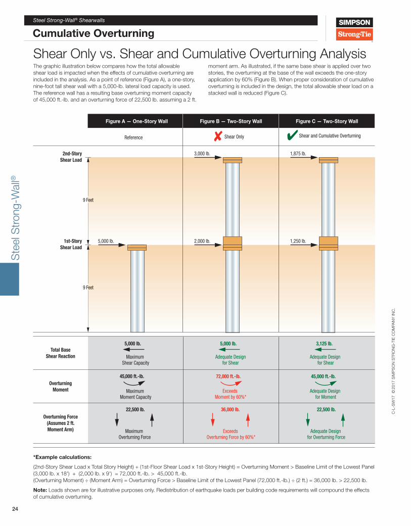
*Example calculations:
(2nd-Story Shear Load x Total Story Height) + (1st-Floor Shear Load x 1st-Story Height) = Overturning Moment > Baseline Limit of the Lowest Panel (3,000 lb. x 18') + (2,000 lb. x 9') = 72,000 ft.-lb. > 45,000 ft.-lb. (Overturning Moment) ÷ (Moment Arm) = Overturning Force > Baseline Limit of the Lowest Panel (72,000 ft.-lb.) ÷ (2 ft.) = 36,000 lb. > 22,500 lb.
Note: Loads shown are for illustrative purposes only. Redistribution of earthquake loads per building code requirements will compound the effects of cumulative overturning.
2nd-StoryShear Load
1st-StoryShear Load
9 Feet
9 Feet
5,000 lb.
Figure A — One-Story Wall
Reference ✘ Shear Only
2,000 lb.
3,000 lb.
✔ Shear and Cumulative Overturning
1,250 lb.
1,875 lb.
Total BaseShear Reaction Maximum
Shear Capacity
5,000 lb.
Adequate Design for Shear
3,125 lb.
Adequate Designfor Shear
5,000 lb.
OverturningMoment Maximum
Moment Capacity
45,000 ft.-lb.
Adequate Design for Moment
45,000 ft.-lb.
Exceeds Moment by 60%*
72,000 ft.-lb.
Overturning Force(Assumes 2 ft.Moment Arm) Maximum
Overturning Force
22,500 lb.
Adequate Design for Overturning Force
22,500 lb.
Exceeds Overturning Force by 60%*
36,000 lb.
Figure B — Two-Story Wall Figure C — Two-Story Wall
Shear Only vs. Shear and Cumulative Overturning Analysis The graphic illustration below compares how the total allowable shear load is impacted when the effects of cumulative overturning are included in the analysis. As a point of reference (Figure A), a one-story, nine-foot tall shear wall with a 5,000-lb. lateral load capacity is used. The reference wall has a resulting base overturning moment capacity of 45,000 ft.-lb. and an overturning force of 22,500 lb. assuming a 2 ft.
moment arm. As illustrated, if the same base shear is applied over two stories, the overturning at the base of the wall exceeds the one-story application by 60% (Figure B). When proper consideration of cumulative overturning is included in the design, the total allowable shear load on a stacked wall is reduced (Figure C).

Ste
el S
tron
g-W
all®
C-L
-SW
17 ©
2017
SIM
PS
ON
STR
ON
G-T
IE C
OM
PAN
Y IN
C.
25
Steel Strong-Wall® Shearwalls
Two-Story Stacked on Concrete FoundationsSimpson Strong-Tie offers a complete stacked-wall solution for two-story applications. This Steel Strong-Wall® Shearwall option combines simplified installation with superior performance.
• Some of the highest loads in the industry and design procedures that account for cumulative overturning, see pages 23–24 for more information.
• Complete concrete-anchorage designs for two-story applications (foundation design by Designer)
• No bearing plates to install, walls can now be placed flush against a corner.
• Uses the same anchor bolt template as single-story installation.
• Compression loads transferred by nut/rod — reducing wood crushing under load.
Material & Finish: See page 10.
Codes: ICC-ES ESR-1679: City of L.A. RR25625;State of Florida FL5113
Two-Story Stacked-Wall Product Data — Bottom Walls
Model No.
W (in.)
H (in.)
T (in.)
Anchor Bolts Number of Screws in Top of
WallQty. Dia. (in.)
SSW15x8-STK 15 93 1⁄4 3 1⁄2 2 1 6SSW18x8-STK 18 93 1⁄4 3 1⁄2 2 1 9SSW21x8-STK 21 93 1⁄4 3 1⁄2 2 1 12SSW24x8-STK 24 93 1⁄4 3 1⁄2 2 1 14SSW15x9-STK 15 105 1⁄4 3 1⁄2 2 1 6SSW18x9-STK 18 105 1⁄4 3 1⁄2 2 1 9SSW21x9-STK 21 105 1⁄4 3 1⁄2 2 1 12SSW24x9-STK 24 105 1⁄4 3 1⁄2 2 1 14SSW15x10-STK 15 117 1⁄4 3 1⁄2 2 1 6SSW18x10-STK 18 117 1⁄4 3 1⁄2 2 1 9SSW21x10-STK 21 117 1⁄4 3 1⁄2 2 1 12SSW24x10-STK 24 117 1⁄4 3 1⁄2 2 1 14SSW15x11-STK 15 129 1⁄4 5 1⁄2 2 1 6SSW18x11-STK 18 129 1⁄4 5 1⁄2 2 1 9SSW21x11-STK 21 129 1⁄4 5 1⁄2 2 1 12SSW24x11-STK 24 129 1⁄4 5 1⁄2 2 1 14SSW15x12-STK 15 141 1⁄4 5 1⁄2 2 1 6SSW18x12-STK 18 141 1⁄4 5 1⁄2 2 1 9SSW21x12-STK 21 141 1⁄4 5 1⁄2 2 1 12SSW24x12-STK 24 141 1⁄4 5 1⁄2 2 1 14SSW18x13-STK 18 153 1⁄4 5 1⁄2 2 1 9SSW21x13-STK 21 153 1⁄4 5 1⁄2 2 1 12SSW24x13-STK 24 153 1⁄4 5 1⁄2 2 1 14
1. See page 11 for product data on top wall.
Two-Story Stacked-Wall Connection KitWall Width
(in.)Model
No. Contents
15 SSW15-2KT (1) Shear-Transfer Plate (with #14 self-drilling screws)(2) 1" x 48" Threaded Rods F1554 Grade 36 (6) Heavy Hex NutsInstallation Instructions
18 SSW18-2KT21 SSW21-2KT24 SSW24-2KT
1. Two heavy hex nuts included with each wall.
Foundation design (size and reinforcement) by Designer
Two-Story Stacked InstallationU.S. Patent 8,281,551; 8,689,518
Canadian Patent 2,489,845
Standard Steel Strong-Wall®
Two-Story Stacked-Wall Connector Kit
Model SSW__-2KT(Sold separately)
Factory installedstacked-wall option —
To order add“-STK” suffix to
the model number(Example:
SSW18x10-STK)
Top Wall:SSW18x8
Steel Strong-Wall Nominal Height (ft.)
Naming Legend
Width(in.)
Stacked Wall(For Bottom Walls Only)
Bottom Wall:SSW18x10-STK
Steel Strong-WallWidth(in.) Nominal Height (ft.)
Suggested Example Specification: SSW18x8 over SSW18x10-STK

Ste
el S
tron
g-W
all®
C-L
-SW
17 ©
2017
SIM
PS
ON
STR
ON
G-T
IE C
OM
PAN
Y IN
C.
26
Steel Strong-Wall® Shearwalls
Two-Story Stacked on Concrete Foundations
First-Story Installation With Wood Floor SystemSee detail 7/SSW2 on page 70.
Height modification options available, contact Simpson Strong-Tie.
Installation Notes • Do not cut the Steel Strong-Wall® or enlarge existing holes, doing so will compromise the performance of the wall.
• Do not use an impact wrench to tighten nuts on the anchor bolts.
• Maximum shim thickness between the Steel Strong-Wall and top plates is 7/8" using Simpson Strong-Tie® Strong-Drive® 1⁄4" x 3 1⁄2" SDS Heavy-Duty Connector screws. For additional shim thicknesses, see detail 5/SSW2 on page 67 and detail 9/SSW2 on page 71.
Shear-Transfer Plate FastenersStrong-Wall
WidthFastener Quantity
#14 Screws 10d Nails15" Wall 4 1018" Wall 6 1221" Wall 6 1624" Wall 7 18
Attach totop plates withSDS ¼" x 3½"
screws(provided)
Shim asnecessaryfor tight fit
Shim asnecessaryfor tight fit
Use SSW__-2KT connectionkit to attach standard wall
above to “-STK” model below
SSWAB1
Place Steel Strong-Wall® over theanchor bolts and secure with heavy hexnuts (provided). Snug tight fit required,do not use an impact wrench.• 1 5/8" wrench/socket required for 1" nut
Blocking/Connection Detail(See detail 8/SSW2 on page 70 for
perpendicular blocking where required)
Solidblocking
under centerand each
end of wallDrill/notch subfloor to allow nut to sit flush with underside of wall (notching of rim joist may also be required) Exterior View of
Shear-Transfer Plate
SSW Shear-Transfer Plate installs with 10d nails into the rim joist and #14 self-drilling screws into the Strong-Wall® (Sold separately with SSW__-2KT)
Simpson Strong-Tie®
A34 each side(sold separately)
Rim joist
Two-Story Stacked-Wall Connection Detail
Installconnectingrods beforeplacing 2ndfloor wall
Attach to top plates with
1⁄4" x 3½" SDS Heavy-Duty
Connector screws
(provided)
Doublenuts
All nutsrequirea snugtight fit
Two-Story Stacked InstallationU.S. Patent 8,281,551; 8,689,518
Canadian Patent 2,489,845

Ste
el S
tron
g-W
all®
C-L
-SW
17 ©
2017
SIM
PS
ON
STR
ON
G-T
IE C
OM
PAN
Y IN
C.
27
Steel Strong-Wall® Shearwalls
Two-Story Stacked on Concrete Foundations
See footnotes above.
1. Allowable base moment and anchor tension are applicable to installation on concrete foundations with minimum f'c = 2,500 psi using the ASD basic (Section 1605.3.1) or the alternative basic (Section 1605.3.2) load combinations. Load values include evaluation of anchor rod compression at second story and bearing stresses at foundation.
2. For seismic designs based on the 2015 IBC using R = 6.5. For other codes, use the seismic coefficients corresponding to light-frame bearing walls with wood structural panels or sheet steel panels.
3. Two-story stacked-wall installations may consist of any height-combination of equal width wall models listed in these tables.
4. Loads are based on a 1,000 lb. maximum uniformly distributed total axial load acting on the second-story panel and a 2,000 lb. maximum uniformly distributed total axial load acting on the first-story panel in combination with the tabulated shear load and base moment.
5. The Designer must verify that the cumulative overturning moment at the base of the first-story Steel Strong-Wall® does not exceed the allowable base moment capacity. See design example on page 24 for procedure.
6. The allowable second-story shear loads assume a maximum floor joist depth of 14". For allowable shear load with up to 18" joists, multiply second-story allowable shear loads by 0.98 for SSW15x models and by 0.94 for other SSW widths. For bottom wall shims greater than 7/8" thick, see detail 9/SSW2 on page 71.
7. Allowable shear, drift, and base moment values may be interpolated for intermediate heights.
8. Minimum ASTM F1554 Grade 36 threaded rods are required at the second-story wall anchorage.
9. High-strength anchor bolts are required at the first-story wall for anchor tension forces exceeding the allowable load for standard-strength bolts tabulated on pages 29–30. See pages 29–35 for SSWAB anchor bolt information and anchorage solutions.
10. Tabulated anchor tension loads assume no resisting axial load. For anchor tension loads at design shear values and including the effect of axial load, refer to the Strong-Wall Selector web application or use the equations on page 15. Drifts at lower design shear or base moment may be linearly reduced.
First-Story Walls On Concrete Foundations5,9
First-StoryWall Models
Seismic2 Wind
Allowable ASD Base Moment
(ft.-lb.)
Drift at Allowable Base Moment
(in.)
Anchor Tension at Allowable
Base Moment10
(lb.)
Allowable ASD Base Moment
(ft.-lb.)
Drift at Allowable Base Moment
(in.)
Anchor Tension at Allowable
Base Moment10
(lb.)SSW15x8-STK 9,665 0.35 11,385 9,665 0.35 11,385SSW18x8-STK 19,270 0.41 19,520 22,690 0.49 24,875SSW21x8-STK 27,665 0.39 23,360 30,775 0.43 27,240SSW24x8-STK 37,805 0.37 27,435 39,670 0.39 29,370SSW15x9-STK 9,490 0.37 11,130 9,490 0.38 11,130SSW18x9-STK 18,815 0.47 18,890 22,685 0.57 24,870SSW21x9-STK 27,585 0.46 23,265 31,310 0.52 27,970SSW24x9-STK 37,585 0.44 27,215 40,390 0.47 30,150
SSW15x10-STK 9,225 0.45 10,755 9,225 0.45 10,755SSW18x10-STK 18,175 0.53 18,030 22,585 0.65 24,690SSW21x10-STK 29,750 0.50 25,905 31,485 0.55 28,210SSW24x10-STK 37,470 0.50 27,100 40,925 0.55 30,740SSW15x11-STK 9,025 0.50 10,475 9,025 0.50 10,475SSW18x11-STK 17,610 0.58 17,295 22,115 0.73 23,880SSW21x11-STK 26,765 0.58 22,325 30,860 0.67 27,355SSW24x11-STK 37,430 0.57 27,060 40,260 0.61 30,005SSW15x12-STK 8,675 0.57 9,990 8,675 0.57 9,990SSW18x12-STK 17,070 0.63 16,605 21,600 0.80 23,030SSW21x12-STK 26,015 0.63 21,490 30,195 0.73 26,475SSW24x12-STK 37,080 0.63 26,710 39,545 0.67 29,235SSW18x13-STK 17,050 0.68 16,580 21,155 0.85 22,315SSW21x13-STK 25,350 0.68 20,765 29,505 0.79 25,590SSW24x13-STK 36,140 0.68 25,790 38,795 0.73 28,450
Second-Story Walls6
Second-Story Wall Models
Seismic2 Wind
Allowable ASD Shear Load V6
(lb.)
Drift at Allowable Shear
(in.)
Allowable ASD Shear Load V6
(lb.)
Drift at Allowable Shear
(in.)
SSW15x7 600 0.21 600 0.21SSW18x7 1,210 0.24 1,390 0.28SSW21x7 1,735 0.23 1,815 0.24SSW24x7 2,330 0.22 2,330 0.22SSW15x8 550 0.26 550 0.26SSW18x8 1,130 0.32 1,315 0.37SSW21x8 1,625 0.30 1,715 0.32SSW24x8 2,050 0.26 2,050 0.26SSW15x9 510 0.31 510 0.31SSW18x9 1,070 0.39 1,220 0.45SSW21x9 1,520 0.36 1,520 0.36SSW24x9 1,815 0.30 1,815 0.30SSW15x10 470 0.37 470 0.37SSW18x10 1,010 0.47 1,095 0.51SSW21x10 1,365 0.39 1,365 0.39SSW24x10 1,630 0.35 1,630 0.35SSW15x11 440 0.43 440 0.43SSW18x11 960 0.55 995 0.57SSW21x11 1,235 0.46 1,235 0.46SSW24x11 1,480 0.39 1,480 0.39SSW15x12 405 0.50 405 0.50SSW18x12 900 0.63 910 0.64SSW21x12 1,130 0.52 1,130 0.52SSW24x12 1,355 0.43 1,355 0.43SSW18x13 830 0.68 840 0.69SSW21x13 1,045 0.57 1,045 0.57SSW24x13 1,250 0.48 1,250 0.48

Ste
el S
tron
g-W
all®
C-L
-SW
17 ©
2017
SIM
PS
ON
STR
ON
G-T
IE C
OM
PAN
Y IN
C.
28
Steel Strong-Wall® Shearwalls
Two-Story Stacked on Concrete Foundations
Two-Story Design ExampleExample: Standard Two-Story Wall DesignGiven:
Wind, f'c = 2,500 psi
V2nd-story wall = 650 lb.
V1st-story wall = 650 lb.
Vtotal = 650 lb. + 650 lb. = 1,300 lb.
Mallow = Allowable ASD Base Moment (ft.-lb.) (See Two-Story Stacked Tables)
Vallow = Allowable ASD Shear Load V (lb.) (See Two-Story Stacked Tables)
Step 1 – Select First-Story Wall (See tables on page 27)
Mbase = (650 lb. x 18 ft.) + (650 lb. x 9 ft.) = 17,550 ft.-lb.
Using First-Story Wall Table, select a 9-foot wall with Mallow ≥ Mbase
Select SSW18x9-STK
Mallow = 22,685 ft.-lb. > 17,550 ft.-lb. OK
Step 2 – Check Second-Story WallUsing the Second-Story Wall Table on page 27, check the capacity of an 8-foot wall with the same width as the First-Story Wall selected in Step 1:
Select SSW18x8
Vallow = 1,315 lb. > 650 lb. OK
❯❯❯ Use SSW18x8 over SSW18x9-STK
Cold-Formed Steel Applications(Standard, Raised Floor and Two-Story)
Cold-Formed Steel on Concrete Foundations
The Steel Strong-Wall® provides high-capacity, narrow- wall solutions for cold-formed steel (CFS) framing. Wall models for this application, designated by the S/SSW model prefix, install easily in CFS framing, and preattached steel studs allow easy attachment of interior and exterior finishes. Simpson Strong-Tie offers Steel Strong-Wall solutions for standard CFS applications on concrete, first-story floor systems, and two-story stacked applications on concrete.
The Cold-Formed Steel Connectors CatalogAll of the design, specification and installation information you need on our Steel Strong-Wall for CFS applications is contained in the Cold-Formed Steel Connectors catalog. In addition to this resource, or to learn more, visit strongtie.com/cfs.
Cover
Connectors for Cold-Formed Steel Construction
C-CF-2017 | (800) 999-5099 | strongtie.com
650 lb.
650 lb.
9 ft.
12" floor
8 ft.

Ste
el S
tron
g-W
all®
C-L
-SW
17 ©
2017
SIM
PS
ON
STR
ON
G-T
IE C
OM
PAN
Y IN
C.
29
Steel Strong-Wall® Shearwalls
SSWAB Anchor BoltsSSWAB anchor bolts in 3/4" and 1" diameters offer flexibility to meet specific project demands. Inspection is easy; the head is stamped with a “No Equal” symbol for identification, bolt length, bolt diameter, and optional “HS” for High Strength if specified.
Material: ASTM F1554 Grade 36; High Strength (HS) ASTM A449
An additional nut for template installation is provided with each SSWAB. It may also be used for SSW installation.
Steel Strong-Wall®
Width(in.)
Model No. Dia.(in.)
Total Length
(in.)
le(in.)
12
SSWAB 3/4 x 24 3/4 24 19SSWAB 3/4 x 24HS 3/4 24 19SSWAB 3/4 x 30 3/4 30 25SSWAB 3/4 x 30HS 3/4 30 25SSWAB 3/4 x 36HS 3/4 36 31
15, 18, 21, 24
SSWAB1x24 1 24 19SSWAB1x24HS 1 24 19SSWAB1x30 1 30 25SSWAB1x30HS 1 30 25SSWAB1x36HS 1 36 31
SSWHSR Extension KitSSWHSR allows for anchorage in tall stemwall applications where full embedment of an SSWAB into the footing is required. The head is stamped for identification like an SSWAB. Kit includes ASTM A449 high-strength rod with heavy hex nut fixed in place and high strength coupler nut. Do not use in place of SSWAB.
Steel Strong-Wall Width (in.)
Model No. Dia.(in.)
Total Length
(in.)
le(in.)
12SSWHSR 3/4 x 2KT 3/4 24 21SSWHSR 3/4 x 3KT 3/4 36 33
15, 18, 21, 24
SSWHSR1x2KT 1 24 21SSWHSR1x3KT 1 36 33
SSWHSRand SSWABAssembly
SSWHSR_KT
1. See pages 32–33 for foundation illustrations showing W and de dimensions.
2. Anchorage designs conform to ACI 318-14 and 318-11 Appendix D with no supplementary reinforcement and cracked or uncracked concrete as noted.
3. Anchor strength indicates required grade of SSWAB anchor bolt. Standard or High Strength (HS).
4. Seismic indicates Seismic Design Category C through F. Detached 1 and 2 family dwellings in SDC C may use wind anchorage solutions. Seismic anchorage designs conform to ACI 318-14 Section 17.2.3.4.3 and ACI 318-11 Section D.3.3.4.
5. Wind includes Seismic Design Category A and B.6. Foundation dimensions are for anchorage only. Foundation
design (size and reinforcement) by Designer. The registered design professional may specify alternate embedment, footing size or anchor bolt.
Total le = SSWHSR le + SSWAB le + 3"
Steel Strong-Wall® Anchorage Solutions — 2,500 psi Concrete1,2,6
Design Criteria
Concrete Condition
Anchor Strength3
SSWAB ¾" Anchor Bolt SSWAB 1" Anchor Bolt
ASD Allowable
Tension (lb.)
W (in.)
de (in.)
ASD Allowable Tension
(lb.)
W (in.)
de (in.)
Seismic4
Cracked
Standard8,800 22 8 16,100 33 11
9,600 24 8 17,100 35 12
High Strength18,500 36 12 33,000 51 17
19,900 38 13 35,300 54 18
Uncracked
Standard8,800 19 7 15,700 28 10
9,600 21 7 17,100 30 10
High Strength18,300 31 11 32,300 44 15
19,900 33 11 35,300 47 16
Wind5
Cracked
Standard
5,100 14 6 6,200 16 6
7,400 18 6 11,400 24 8
9,600 22 8 17,100 32 11
High Strength
11,400 24 8 21,100 36 12
13,600 27 9 27,300 42 14
15,900 30 10 31,800 46 16
19,900 35 12 35,300 50 17
Uncracked
Standard
5,000 12 6 6,400 14 6
7,800 16 6 12,500 22 8
9,600 19 7 17,100 28 10
High Strength
12,500 22 8 21,900 32 11
14,300 24 8 26,400 36 12
17,000 27 9 31,500 40 14
19,900 30 10 35,300 43 15
Anchorage Solutions
HX on Extension Kit
Top ofconcrete
le
3/43"
24HX
Leng
thHeavy hex nut fixed in place
3/4" or 1"high-strength rod
High-strengthcoupler nut
Top ofconcrete
SSWHSR
Cut to lengthas necessary
High-strengthcoupler nut
SSWAB
le
le
3"
Heavy hex nutfixed in placeon all SSWABanchor bolts
Top ofConcrete
Heavyhex nut
Heavyhex nut
Platewasher
le
3"
Leng
th
3/4 24HS
SSWAB

Ste
el S
tron
g-W
all®
C-L
-SW
17 ©
2017
SIM
PS
ON
STR
ON
G-T
IE C
OM
PAN
Y IN
C.
30
Steel Strong-Wall® Shearwalls
Anchorage Solutions
Steel Strong-Wall® Anchorage Solutions — 3,500 psi Concrete1,2,6
Design Criteria Concrete Condition
Anchor Strength3
SSWAB ¾" Anchor Bolt SSWAB 1" Anchor BoltASD Allowable Tension (lb.)
W (in.)
de (in.)
ASD Allowable Tension (lb.)
W (in.)
de (in.)
Seismic4
CrackedStandard
9,000 20 7 15,700 29 109,600 21 7 17,100 31 11
High Strength18,200 32 11 32,900 46 1619,900 34 12 35,300 48 16
UncrackedStandard
8,800 17 6 15,700 25 99,600 19 7 17,100 27 9
High Strength18,600 28 10 32,600 40 1419,900 30 10 35,300 42 14
Wind5
Cracked
Standard6,000 14 6 7,300 16 67,300 16 6 13,500 24 89,600 20 7 17,100 29 10
High Strength
11,800 22 8 22,700 34 1213,500 24 8 27,400 38 1317,000 28 10 32,300 42 1419,900 32 11 35,300 45 15
Uncracked
Standard6,000 12 6 7,500 14 67,500 14 6 12,800 20 79,600 17 6 17,100 25 9
High Strength
12,800 20 7 21,300 28 1014,800 22 8 26,000 32 1116,900 24 8 31,300 36 1219,900 27 9 35,300 39 13
Steel Strong-Wall® Anchorage Solutions — 4,500 psi Concrete1,2,6
Design Criteria Concrete Condition
Anchor Strength3
SSWAB ¾" Anchor Bolt SSWAB 1" Anchor BoltASD Allowable Tension (lb.)
W (in.)
de (in.)
ASD Allowable Tension (lb.)
W (in.)
de (in.)
Seismic4
CrackedStandard
8,700 18 6 16,000 27 99,600 20 7 17,100 29 10
High Strength17,800 29 10 32,100 42 1419,900 32 11 35,300 45 15
UncrackedStandard
9,100 16 6 15,700 23 89,600 17 6 17,100 25 9
High Strength17,800 25 9 32,500 37 1319,900 27 9 35,300 39 13
Wind5
Cracked
Standard5,400 12 6 6,800 14 68,300 16 6 11,600 20 79, 600 18 6 17,100 26 9
High Strength
11,600 20 7 21,400 30 1013,400 22 8 25,800 34 1217,300 26 9 31,000 38 1319,900 29 10 35,300 42 14
Uncracked
Standard6,800 12 6 6,800 12 68,500 14 6 12,400 18 69,600 16 6 17,100 23 8
High Strength
12,400 18 6 21,600 26 914,500 20 7 26,700 30 1016,800 22 8 32,200 34 1219,900 25 9 35,300 36 12
1. See pages 32–33 for foundation illustrations showing W and de dimensions.
2. Anchorage designs conform to ACI 318-14 and ACI 318-11 Appendix D with no supplementary reinforcement and cracked or uncracked concrete as noted.
3. Anchor strength indicates required grade of SSWAB anchor bolt. Standard or High Strength (HS).
4. Seismic indicates Seismic Design Category C through F. Detached 1 and 2 family dwellings in SDC C may use wind anchorage solutions. Seismic anchorage designs conform to ACI 318-14 Section 17.2.3.4.3 and ACI 318-11 Section D.3.3.4.
5. Wind includes Seismic Design Category A and B.6. Foundation dimensions are for anchorage only. Foundation design
(size and reinforcement) by Designer. The registered design professional may specify alternate embedment, footing size or anchor bolt.

Ste
el S
tron
g-W
all®
C-L
-SW
17 ©
2017
SIM
PS
ON
STR
ON
G-T
IE C
OM
PAN
Y IN
C.
31
Steel Strong-Wall® Shearwalls
Anchorage Solutions
Model L t or L h (in.)
Seismic3 Wind4
Shear Reinforcement
Minimum Curb/ Stemwall
Width (in.)
Shear Reinforcement
Minimum Curb/ Stemwall
Width (in.)
ASD Allowable Shear Load V6 (lb.)
6" Minimum Curb/Stemwall 8" Minimum Curb/Stemwall
Uncracked Cracked Uncracked Cracked
SSW12 9 (1) #3 Tie 6 See Note 6 — 1,230 880 1,440 1,030
SSW15 12 (2) #3 Ties 6 See Note 6 — 1,590 1,135 1,810 1,295
SSW18 14 (1) #3 Hairpin 85 (1) #3 Hairpin 6Hairpin reinforcement achieves maximum
allowable shear load of the Steel Strong-Wall®.SSW21 15 (2) #3 Hairpins 85 (1) #3 Hairpin 6
SSW24 17 (2) #3 Hairpins 85 (1) #3 Hairpin 6
1. Shear anchorage designs conform to ACI 318-14 and 318-11 and assume minimum f'c = 2,500 psi concrete. See pages 29–30 for tension anchorage.
2. Shear reinforcement is not required for panels installed on a wood floor, interior foundation applications (panel installed away from edge of concrete), or braced-wall panel applications.
3. Seismic indicates Seismic Design Category C through F. Detached 1 and 2 family dwellings in SDC C may use wind anchorage solutions. Seismic shear reinforcement designs conform to ACI 318-14 Section 17.2.3.5.3 and ACI 318-11 Section D.3.3.5.
4. Wind includes Seismic Design Category A and B.5. Where noted minimum curb/stemwall width is 6" when standard-strength
SSWAB is used.6. Use (1) #3 tie for SSW12 and SSW15 when the Steel Strong-Wall® design
shear force exceeds the tabulated anchorage allowable shear load.7. #4 grade 40 shear reinforcement may be substituted for SSW shear
anchorage solutions. 8. The registered design professional may specify alternate shear anchorage.
Steel Strong-Wall® Shear Anchorage Foundation shear reinforcement to resist shear forces from Strong-Wall® shearwalls located at the edge of concrete is shown in the table below. The SSW12 and SSW15 used in wind applications do not require shear reinforcement when the shearwall design shear force is less than the anchorage allowable shear load shown in the table below.
Hairpin Installation(Garage curb shown, other footing types similar)
SSWAB#3 hairpin (#3 tie similar),see table for required quantity.
1 1⁄2" clr. 1 1⁄2" spacing
Hairpin Shear Reinforcement
L h min.
3"
SSWAB Field tie and secure duringconcrete placement. Overlap
varies with bolt spacing.
#3 hairpingrade 60 rebar
(min.)
Tie Shear Reinforcement
L t
4" min.
3"
SSWAB Field tie and secureduring concrete
placement
#3 tiegrade 60 rebar
(min.)

Ste
el S
tron
g-W
all®
C-L
-SW
17 ©
2017
SIM
PS
ON
STR
ON
G-T
IE C
OM
PAN
Y IN
C.
32
Steel Strong-Wall® Shearwalls
Anchorage Solutions
Foundation design (size and reinforcement) by Designer.
Curb or Stemwall Section View
Slab-on-Grade Section View
Brick Ledge Section View
Anchorage Solutions General Notes
1. The Designer may specify alternate embedment, footing size or bolt grade.
2. Footing dimensions and rebar requirements are for anchorage only.
Curb or Stemwall Installation
Slab-on-Grade Installation
Brick Ledge Installation
SSWAB
3" clr. min.
3" clr. min.
3" clr. min.
SSWAB
SSWAB
Minimum curb/stemwallwidth per page 31
Shear reinforcementper page 31 when required
Shear reinforcementper page 31 whenrequired
Minimum curb/stemwallwidth per page 31
Shear reinforcementper page 31 when required
Perspective View(Slab not shown for clarity)
Perspective View
Perspective View
1⁄2 W 1⁄2 W
de
de
de
H
H
H
3"
3"
3"
1⁄2 W
1⁄2 W
W
W
W
1⁄2 W
1⁄2 W
½W ½WB
½W
½W
W
Footing Plan
½W ½WB
½W
½W
W
½W ½WB
½W
½W
W
Footing Plan
Footing Plan

Ste
el S
tron
g-W
all®
C-L
-SW
17 ©
2017
SIM
PS
ON
STR
ON
G-T
IE C
OM
PAN
Y IN
C.
33
Steel Strong-Wall® Shearwalls
Anchorage Solutions
Anchorage Solutions General Notes
1. The Designer may specify alternate embedment, footing size or bolt grade.
2. Footing dimensions and rebar requirements are for anchorage only.
Steel Strong-Wall® Anchor Bolt Layout
WallModel
DistanceFrom End of Wall
to Center ofSSWABs(A) (in.)
DistanceFrom Centerto Center of
SSWABs(B) (in.)
Distance From Exterior Face of Wall to Center of All SSWABs
(C) (in.)
SSW12 2 9⁄16 6 7/8 2
SSW15 2 7/8 9 1⁄4 1 7/8
SSW18 2 7/8 12 1⁄4 1 7/8
SSW21 2 7/8 15 1⁄4 1 7/8
SSW24 2 7/8 18 1⁄4 1 7/8
Interior Section View
Interior Installation
½W B ½W
½W
½W
W
Footing Plan
2x4 preattachedstud for modelsup to 10 feet tall
2x6 preattachedstud for models
taller than 10 feet
A B
C3 1⁄2"
1⁄2 W
W
1⁄2 W
3" clr. min.
de
3"
SSWAB
Stemwall Extension Installation
Section at StemwallSSWAB and SSWHSRExtension Application
Minimum stemwallwidth per page 31
Shear reinforcementper page 31 whenrequired
SSWHSR
SSWAB
1⁄2 W min. 1⁄2 W min.
W
3" clr. min.
de
3"
Max. stemwallheight =
(SSWAB le +SSWHSR le +
3"- de )See page 29 forle dimensions

Ste
el S
tron
g-W
all®
C-L
-SW
17 ©
2017
SIM
PS
ON
STR
ON
G-T
IE C
OM
PAN
Y IN
C.
34
Steel Strong-Wall® Shearwalls
Anchor Reinforcement Solutions on Grade Beams
Simpson Strong-Tie now provides grade beam anchorage solutions for the Steel Strong-Wall®, which have been calculated to conform to ACI 318-14. Through funding from the Structural Engineers Association of Northern California, initial testing at Scientific Construction Laboratories Inc. confirmed the need to comply with ACI 318 requirements to prevent plastic hinging at anchor locations. Follow-up testing at the Simpson Strong-Tie Tyrell Gilb Research Laboratory was then used to confirm these findings and validate performance. The testing consisted of specimens with closed tie anchor reinforcement, non-closed u-stirrups and control specimens without anchor reinforcement. Flexural and shear reinforcement were designed to resist amplified anchorage forces and compared to test beams designed for non-amplified strength level forces. The test program has proven the performance of the anchor reinforcement details developed by Simpson Strong-Tie.
Significant Findings From Testing:Grade beam flexural and shear capacity is critical to anchor performance and must be designed to exceed the demands created by the attached structure. In wind load applications, this demand includes the factored demand from the Steel Strong-Wall (SSW) shearwall. In seismic applications, testing and analysis have shown that in order to achieve the anchor performance expected by ACI 318 anchorage design methodologies, the concrete member design strength needs to resist the amplified anchor design demand from ACI 318-14 Section 17.2.3.4.3 and ACI 318-11 Appendix D Section D.3.3.4.3. To help designers achieve this, Simpson Strong-Tie recommends designers apply the seismic design moment listed in the table below at the SSW location when evaluating the grade beam design strength under seismic loads. The tabulated moment correlates to the lowest of the anchor tension design limits defined in the sections listed above as they relate to each SSW model.
Closed tie anchor reinforcement is critical to maintain the integrity of the reinforced core where the anchor is located. Testing with u-stirrups that did not include complete closed ties showed premature splitting failure of the grade beam.
Grade Beam Testing
SSW Grade Beam Anchorage DetailSee page 65 for additional grade beam anchor
reinforcement details and requirements
Steel Strong-Wall Grade Beam Anchorage Solutions
Steel Strong-Wall Model
Anchor Bolt Model No.
Anchor Diameter (in.)
Anchor Reinforcement for Wind and Seismic Amplified LRFD Applied Design Seismic Moment (ft.-lb.)
Standard-Strength SSWAB
High-Strength SSWABHS
Standard-Strength SSWAB
High-Strength SSWABHS
SSW12 SSWAB3/4 3/4 (2) #4 Closed Ties / Wall (5) #4 Closed Ties / Wall 16,700 23,000
SSW15
SSWAB1 1
(4) #4 Closed Ties / Wall (7) #4 Closed Ties / Wall 37,000 44,000
SSW18
(2) #4 Closed Ties / Anchor (4) #4 Closed Ties / Anchor
48,700 61,000
SSW21 60,300 77,000
SSW24 72,000 87,000
1. Anchor reinforcement conforms to ACI 318-14 Section 17.2.4.9 and ACI 318-11, section D.5.2.9. Full-scale testing was used to validate anchor reinforcement configuration and placement.
2. Minimum concrete compressive strength, f'c = 2,500 psi.3. Closed-tie anchor reinforcement to be ASTM A615 Grade 60 (min.) #4 rebar.4. Grade beam longitudinal and tie reinforcement shall be specified by the registered
design professional for flexure and shear loading. Design should consider project specific design loads and allowable soil pressure.
5. Simpson Strong-Tie recommends using the tabulated minimum LRFD-applied seismic design moment to ensure grade-beam design flexure and shear strength is adequate to prevent plastic hinge formation under demands associated with anchorage forces corresponding to ACI 318-14 Section 17.2.3.4.3 and ACI 318-11, Section D.3.3.4.3.
6. Designer may use reduced moment due to applied SSW lateral load. Minimum moment shall be the lesser of the tabulated moment or the amplified LRFD design moment for seismic: (ASD design demand Shear/0.7) x Ω o x SSW height for grade beam design.
7. Minimum grade beam design moment for wind and seismic in Seismic Design Category A and B and detached one- and two-family dwellings in SDC C: (ASD design demand Shear/0.6) x SSW height.
8. Closed tie may be single piece hoop or two piece assembly with a u-stirrup with 135 degree hooks and a top cross tie cap. See detail 6/SSW1.1.
9. See details for grade-beam anchor reinforcement placement, installation and spacing requirements. Closed-tie anchor reinforcement quantity is per wall for the 12" and 15" wall models, and per anchor for the 18", 21" and 24" models.
GRADE BEAM ELEVATION AT 18", 21" AND 24" WALL MODELSSSW1.1
1
SSWAB1
GRADE BEAM SHEAR TIEREINFORCEMENT BY REGISTEREDDESIGN PROFESSIONAL
CONTINUOUS GRADE BEAMTOP AND BOTTOM REINFORCEMENTBY REGISTERED DESIGN PROFESSIONAL
SHEAR REINFORCEMENT PER4/SSW1 WHEN REQUIRED.
10" MAX
5" MAX
EQ.EQ.EQ.
5" MAX
10" MAX
EQ.EQ.EQ.
CLOSED TIEANCHOR REINFORCEMENTPER TABLE
SSWAB1HS
SSW1.13
SSW1.14
3 1 2 4 3 1 2 4
PLACE ANCHOR REINFORCEMENT WHEREINDICATED BASED ON REQUIRED QUANTITY(EX. 2 TIES REQUIRED: PLACE ATLOCATIONS MARKED 1 AND 2)

Ste
el S
tron
g-W
all®
C-L
-SW
17 ©
2017
SIM
PS
ON
STR
ON
G-T
IE C
OM
PAN
Y IN
C.
35
Steel Strong-Wall® Shearwalls
Anchor Bolt Templates
SSWT Exterior Installation*(May be used for steel form systems)
U.S. Patent 7,445,192
SSWTBL(Brick ledge)
U.S. Patent 7,445,192
SSWT Interior* Installation
U.S. Patent 7,445,192
SSWTEL with Anchor Bolt Stabilizers(Extended Leg)
Allows for placement of Steel Strong-Wall flush with inside face of 2x6 framed exterior wall
U.S. Patent 7,445,192
(Note: Anchor bolt stabilizers are sold separately. Optional T-shape
dowel by others. )
*SSWT templates are reversible. Use the same template for
interior or exterior applications.
SSWTPF (Panel form)
U.S. Patent 7,445,192
Top of concrete
An additional nut for template installation is provided with each SSWAB. It may also be used for SSW installation.
Anchor Bolt Height
1 1⁄2"3"
3"
Simpson Strong-Tie now offers anchor bolt stabilizers that may be used with all anchor template models. The bolt stabilizer enables the Steel Strong-Wall anchorage to be installed without being tied to the footing rebar cage by helping to eliminate movement of the anchor bolts during concrete placement. Two bolt stabilizers are used for each SSW anchor assembly; one at the embedded plate washer and the other above the template. Half-inch diameter dowels (not supplied) are then driven down through the bolt stabilizers and into the ground to ensure plumb installation of the anchors and prevent movement during concrete placement. Immediately following concrete placement, the dowels are removed and reused in other locations.
Steel Strong-Wall® Anchor Bolt TemplatesSteel
Strong-Wall Model
Width (in.)
Anchor Bolt Stabilizer
Model
Steel Strong-Wall Template Model
Reversible Panel Form Brick Ledge Extended Leg
SSW12 12 SSWBS12 SSWT12 SSWTPF12 SSWTBL12 SSWTEL12
SSW15 15 SSWBS15 SSWT15 SSWTPF15 SSWTBL15 SSWTEL15
SSW18 18 SSWBS18 SSWT18 SSWTPF18 SSWTBL18 SSWTEL18
SSW21 21 SSWBS21 SSWT21 SSWTPF21 SSWTBL21 SSWTEL21
SSW24 24 SSWBS24 SSWT24 SSWTPF24 SSWTBL24 SSWTEL24
1. The height of the garage curb above the garage slab is critical for rough header opening at garage return walls.2. See Garage Header Rough Opening Height table on page 16.3. Templates are recommended and are required in some jurisdictions.4. Foundation design by Designer.5. Reversible, panel form and brick ledge templates are the same for 4"- or 6"-thick walls.

Str
ong-
Wal
l® W
ood
She
arw
all
C-L
-SW
17 ©
2017
SIM
PS
ON
STR
ON
G-T
IE C
OM
PAN
Y IN
C.
36
Strong-Wall® Wood Shearwall Features
Delivering Easy-To-Install, Code-Listed SolutionsThe Simpson Strong-Tie® Strong-Wall® Wood Shearwall is a specially designed, prefabricated, engineered-wood panel that helps structures resist lateral forces such as those created by earthquakes and high winds. The Strong-Wall® Wood Shearwall has been evaluated to the 2015 International Building Code® (IBC) and can help you resist these forces efficiently and confidently with the following features:
• Code Listed — ICC-ES ESR-2652, City of L.A. RR 25730, and State of Florida FL5113 evaluated to the 2015 IRC/IBC
• Field Adjustable — Can be field-trimmed and drilled
• Stronger Wall — Narrow panel widths have significantly higher allowable loads than the original Wood Strong-Wall
• More Applications — Suitable for residential, multi-family, and light-frame commercial construction and in balloon-framing applications up to 20 ft.
• Easy Access — Newly designed front, side and back access holdowns allow for easier anchor bolt installation and inspection
• Easy to Install — Reusable templates locate the required holdown anchor bolts accurately in the foundation
• Support and Service — Simpson Strong-Tie provides unmatched engineering technical support and experienced field representation
Field AdjustableEngineering Technical Support
Code Listed

Str
ong-
Wal
l® W
ood
She
arw
all
C-L
-SW
17 ©
2017
SIM
PS
ON
STR
ON
G-T
IE C
OM
PAN
Y IN
C.
37
Strong-Wall® Wood Shearwalls
Strong-Wall® Wood Shearwall Applications
Portal Application
Balloon- Framing Application
Two-Story Stacked
ApplicationStandard
Application
Two-Story Stacked
Application
Portal Applications • Narrow wall spaces • Garages • Large windows and doors • Increased capacities when used in a portal
Standard and Balloon-Framing Applications • Narrow wall spaces • Wall heights up to 20'
Two-Story Stacked Application • Narrow wall spaces • Multi-story installation kit (MSK) required (order separately)
• Total assembled heights up to 24'
Product StorageProtect product from sun and water
CAUTION:Wrap is slippery when wet or icy
Use support blocks at 10' on-center to keep bundles
out of mud and water

Str
ong-
Wal
l® W
ood
She
arw
all
C-L
-SW
17 ©
2017
SIM
PS
ON
STR
ON
G-T
IE C
OM
PAN
Y IN
C.
38
Strong-Wall® Wood Shearwalls
Product and Kit Descriptions
Standard Product DescriptionAll Strong-Wall® Wood Shearwalls are supplied with top-of-wall shear transfer plates, nuts, washers, and installation instructions. Additionally, shearwalls 100 inches or less in height are supplied with four portal straps.
Front View
Back View

Str
ong-
Wal
l® W
ood
She
arw
all
C-L
-SW
17 ©
2017
SIM
PS
ON
STR
ON
G-T
IE C
OM
PAN
Y IN
C.
Strong-Wall® Wood Shearwalls
39
Product and Kit Descriptions
Portal Kits(Included with all panels 100" or less in height)
Required for portal-frame applications. Kit includes four portal straps and comes standard with all panels that are 100" or less in height. Order the kit separately if using panels that are more than 100" tall in a portal application.
Model No.: WSW-PK
Multi-Story Kits (MSK)Required for two-story stacked applications. Kit includes two holdowns with preattached bolts and a bearing block. See pages 48–49 for two-story stacked details.
Model No.: WSW-MSK18KT and WSW-MSK24KT
Alternative Top Connection KitRequired for alternative top connections using a single WSW-TOW plate installed from only one side with Strong-Drive® Connector screws.
The 4CUT point reduces installation torque and makes driving easier.
S6
Threadlength
6"
S6
Thre
adle
ngth
6"
Identification on all SDS
screw heads
Strong-Drive® SDS HEAVY-DUTY
CONNECTOR Screw U.S. Patent 6,109,850;5,897,280; 7,101,133
Strong-Wall® Wood Shearwall Alternative Connection Kit
Model No. Contents
WSW-TOW12KT (20) #10 x 1½" SD Connector Screws (2) ¼" x 6" SDS Heavy-Duty Connector Screws
WSW-TOW18KT (28) #10 x 1½" SD Connector Screws (4) ¼" x 6" SDS Heavy-Duty Connector Screws
WSW-TOW24KT (40) #10 x 1½" SD Connector Screws (8) ¼" x 6" SDS Heavy-Duty Connector Screws
1. Use kit fasteners to attach (1) of the (2) WSW-TOWXXKT plates included with the Strong-Wall Wood shearwall. Plate may be installed on either panel face.
1½"
1015
Strong-Drive® SD10 CONNECTOR Screw
U.S. Patent 7,101,133
Identification on all SD
screw heads 1½"
1015

Str
ong-
Wal
l® W
ood
She
arw
all
C-L
-SW
17 ©
2017
SIM
PS
ON
STR
ON
G-T
IE C
OM
PAN
Y IN
C.
40
Strong-Wall® Wood Shearwalls
Standard and Balloon Framing on Concrete Foundations
Strong-Wall®Wood Shearwall
First-Story Installation with Wood Floor SystemSpecify panel height from top of foundation
to underside of the top plates or beam.
Rake Wall Application
Strong-Wall® Wood Shearwall
Simpson Strong-Tie® LTP4 or A35 framing angles
¼" x 6" SDS screws(order separately)
Verify panel is plumb.Use metal shims
(Model No. WSW-CS1)at the base if required.
Maximum ⅞"shim as necessary for tight fit
Place Strong-Wall® Wood Shearwall over the anchor bolts and secure with hex nuts and structural washers (provided). Snug tight fit required.
Foundation design(size and reinforcement)
by Designer.
• 15⁄16" wrench required for ⅞" nut.• 1½" wrench required for 1" nut.
H
W
Standard Installation
Strong-Wall® Wood Shearwall Product Data
Model No.
W (in.)
H (in.)
Anchor Bolts Total Wall Weight
(lb.)Quantity Diameter (in.)
WSW12x7 12 78 2 7/8 100WSW18x7 18 78 2 7/8 145
WSW12x7.5 12 85 1⁄2 2 7/8 110WSW18x7.5 18 85 1⁄2 2 7/8 155WSW12x8 12 93 1⁄4 2 7/8 115WSW18x8 18 93 1⁄4 2 7/8 165WSW24x8 24 93 1⁄4 2 1 225WSW12x9 12 105 1⁄4 2 7/8 130WSW18x9 18 105 1⁄4 2 7/8 185WSW24x9 24 105 1⁄4 2 1 245
WSW12x10 12 117 1⁄4 2 7/8 140WSW18x10 18 117 1⁄4 2 7/8 205WSW24x10 24 117 1⁄4 2 1 270WSW12x11 12 129 1⁄4 2 7/8 150WSW18x11 18 129 1⁄4 2 7/8 220WSW24x11 24 129 1⁄4 2 1 295WSW12x12 12 141 1⁄4 2 7/8 165WSW18x12 18 141 1⁄4 2 7/8 240WSW24x12 24 141 1⁄4 2 1 320WSW18x13 18 153 1⁄4 2 7/8 255WSW24x13 24 153 1⁄4 2 1 345WSW24x14 24 168 2 1 375WSW24x16 24 192 2 1 425WSW18x20 18 240 2 7/8 385WSW24x20 24 240 2 1 520
1. For heights not listed, order the next tallest panel and trim to fit. Minimum trimmed height for all panels is 74½".
2. All panels come with two preattached holdowns, two standard hex nuts, two flat washers, two WSW-TOW top-connection plates (width based on panel model), and installation instructions.
3. All panels are 3½" thick.
WSW designed to provide 1/8" gap between LSL at base of WSW and concrete. Ensure concrete is level and smooth beneath panel. Grind or fill as necessary.

Str
ong-
Wal
l® W
ood
She
arw
all
C-L
-SW
17 ©
2017
SIM
PS
ON
STR
ON
G-T
IE C
OM
PAN
Y IN
C.
Strong-Wall® Wood Shearwalls
41
Standard and Balloon Framing on Concrete Foundations
Simpson Strong-Tie® Strong-Wall® Wood Shearwalls combine design flexibility with performance. Field trimmable, they can be customized to accommodate varying heights or rake walls. They are evaluated to the 2015 IRC/IBC and are listed by ICC-ES in ESR-2652 and the City of LA in RR 25730.
Installation• All panels may be field trimmed to a minimum of 74½".
Trim height from top of panel only, do not trim from sides or bottom. Drilling holes in the Strong-Wall® Wood Shearwalls is not allowed except as shown on page 88.
• Anchor-bolt nuts should be snug tight.
• Maximum shim thickness between the shearwall and top plates or header is 7/8". For additional shim thicknesses, see details 9/WSW2 on page 87.
• Walls may also be used in 2x6 wall framing. Install the panel flush to the outside face of the framing and add furring to the opposite side. See details 6/WSW2 on page 85 and 4/WSW4 on page 93.
• Standard top-of-wall connections install with nails.
Codes: ICC-ES ESR-2652, City of L.A. RR 25730 and State of Florida FL5113
WSW18x8-93
Wood Shearwall Width
(in.)Nominal Height
(ft.)
Actual Height (in.)
Strong-Wall® Wood Shearwall Naming Legend
WSW-TOWstandard oralternative topconnection.
Field trimmableand drillable.
WSW-AB
Foundation design(size and reinforcement)by Designer.
Attaches to headeror top plates.
Precut chasefor wiring and
openings forplumbing and
electrical.
Hex nut andstructural washer.
Form-mountedtemplates enable
precise anchorbolt placement
before the pour.
Standard Installation
Standard Top ConnectionAlso applicable for portal applications with a header.
Maximum⅞" shim asnecessaryfor tight fit.
WSW-TOW installs with 10d x 2½"
min. length nails.
WSW-TOW (providedwith WSW) installedfrom front and back.
Align WSW-TOWnotches with bottom
of top plates.
1015
1015
1015
1015
1015
1015
1015
1015
1015
1015
1015
1015
1015
1015
1015
1015
1015
1015
1015
1015
1015
1015
1015
1015
1015
1015
1015
1015
WSW-TOW installs with acombination of ¼" x 6" SDS Heavy-Duty Connector screwsand #10 x 1½" SD Connectorscrews (order separately asWSW-TOWXXKT).
Max ⅞" shimas necessaryfor tight fit.
Align WSW-TOWnotches with bottom
of top plates.
WSW-TOW (providedwith WSW) installed
on one side only.
Alternative Top ConnectionAlso applicable for portal applications with a header.
1/4" x 6" SDSHeavy-DutyConnector
screw
#10 x 1½" SD Connector screw
Optional 1"-diameterby 1/4"-deep counterbore.
Approx.30o
Alternative Top ConnectionSide View

Str
ong-
Wal
l® W
ood
She
arw
all
C-L
-SW
17 ©
2017
SIM
PS
ON
STR
ON
G-T
IE C
OM
PAN
Y IN
C.
42
Strong-Wall® Wood Shearwalls
Standard and Balloon Framing on Concrete Foundations
Strong-Wall® Wood Shearwall Standard Application on Concrete Foundation
Strong-Wall Wood
Shearwall Model9
Allowable Vertical Load, P
(lb.)4
2,500 psi Concrete 3,000 psi Concrete
Seismic3 Wind Seismic3 Wind
Allowable ASD Shear
Load, V (lb.)
Drift at Allowable Shear, Δ (in.)10
Anchor Tension at Allowable Shear, T (lb.)11
Allowable ASD Shear
Load, V (lb.)
Drift at Allowable Shear, Δ (in.)10
Anchor Tension at Allowable Shear, T (lb.)11
Allowable ASD Shear
Load, V (lb.)
Drift at Allowable Shear, Δ (in.)10
Anchor Tension at Allowable Shear, T (lb.)11
Allowable ASD Shear
Load, V (lb.)
Drift at Allowable Shear, Δ (in.)10
Anchor Tension at Allowable Shear, T (lb.)11
WSW12x7
1,000 1,065 0.31 10,285 1,380 0.43 13,375 1,065 0.31 10,285 1,380 0.43 13,375
4,000 1,065 0.31 10,285 1,380 0.43 13,375 1,065 0.31 10,285 1,380 0.43 13,375
7,500 1,065 0.31 10,285 1,380 0.43 13,370 1,065 0.31 10,285 1,380 0.43 13,375
WSW18x7
1,000 2,475 0.31 13,865 2,980 0.40 16,675 2,475 0.31 13,865 3,225 0.43 18,040
4,000 2,475 0.31 13,865 2,710 0.36 15,160 2,475 0.31 13,865 3,225 0.43 18,040
7,500 2,475 0.31 13,865 2,395 0.32 13,395 2,475 0.31 13,865 2,910 0.39 16,280
WSW24x79
1,000 5,515 0.29 22,710 5,515 0.32 22,710 5,515 0.29 22,710 5,515 0.32 22,710
4,000 5,515 0.29 22,710 5,400 0.31 22,240 5,515 0.29 22,710 5,515 0.32 22,710
7,500 5,515 0.29 22,710 4,950 0.29 20,390 5,515 0.29 22,710 5,515 0.32 22,710
WSW12x8
1,000 960 0.39 11,125 1,245 0.53 14,420 960 0.39 11,125 1,245 0.53 14,420
4,000 960 0.39 11,125 1,245 0.53 14,420 960 0.39 11,125 1,245 0.53 14,420
7,500 960 0.39 11,125 1,155 0.49 13,370 960 0.39 11,125 1,245 0.53 14,420
WSW18x8
1,000 2,430 0.39 16,245 2,490 0.42 16,675 2,430 0.39 16,245 2,925 0.50 19,560
4,000 2,430 0.39 16,245 2,265 0.38 15,160 2,430 0.39 16,245 2,695 0.46 18,045
7,500 2,430 0.39 16,245 2,000 0.34 13,395 2,430 0.39 16,245 2,435 0.41 16,280
WSW24x8
1,000 4,945 0.37 24,355 4,840 0.40 23,830 4,945 0.37 24,355 5,515 0.45 27,150
4,000 4,945 0.37 24,355 4,515 0.37 22,240 4,945 0.37 24,355 5,360 0.44 26,395
7,500 4,945 0.37 24,355 4,140 0.34 20,390 4,945 0.37 24,355 4,985 0.41 24,540
WSW12x9
1,000 790 0.43 10,310 1,020 0.60 13,335 790 0.43 10,310 1,020 0.60 13,335
4,000 790 0.43 10,310 1,020 0.60 13,335 790 0.43 10,310 1,020 0.60 13,335
7,500 790 0.43 10,310 1,020 0.60 13,335 790 0.43 10,310 1,020 0.60 13,335
WSW18x9
1,000 1,920 0.43 14,505 2,210 0.53 16,675 1,920 0.43 14,505 2,515 0.60 18,980
4,000 1,920 0.43 14,505 2,010 0.48 15,160 1,920 0.43 14,505 2,390 0.57 18,045
7,500 1,920 0.43 14,505 1,775 0.42 13,395 1,920 0.43 14,505 2,155 0.51 16,280
WSW24x9
1,000 4,190 0.43 23,275 4,290 0.46 23,830 4,190 0.43 23,275 5,035 0.54 27,985
4,000 4,190 0.43 23,275 4,000 0.43 22,240 4,190 0.43 23,275 4,750 0.51 26,395
7,500 4,190 0.43 23,275 3,670 0.40 20,390 4,190 0.43 23,275 4,415 0.48 24,540
WSW12x10
1,000 630 0.50 9,175 810 0.67 11,810 630 0.50 9,175 810 0.67 11,810
4,000 630 0.50 9,175 810 0.67 11,810 630 0.50 9,175 810 0.67 11,810
7,500 630 0.50 9,175 810 0.67 11,810 630 0.50 9,175 810 0.67 11,810
WSW18x10
1,000 1,715 0.49 14,440 1,980 0.59 16,675 1,715 0.49 14,440 2,225 0.67 18,715
4,000 1,715 0.49 14,440 1,800 0.54 15,160 1,715 0.49 14,440 2,145 0.64 18,045
7,500 1,715 0.49 14,440 1,590 0.48 13,395 1,715 0.49 14,440 1,935 0.58 16,280
WSW24x10
1,000 3,675 0.48 22,740 3,850 0.54 23,830 3,675 0.48 22,740 4,520 0.63 27,985
4,000 3,675 0.48 22,740 3,590 0.50 22,240 3,675 0.48 22,740 4,265 0.60 26,395
7,500 3,675 0.48 22,740 3,295 0.46 20,390 3,675 0.48 22,740 3,965 0.55 24,540
WSW12x11
1,000 575 0.55 9,190 735 0.73 11,810 575 0.55 9,190 735 0.73 11,810
4,000 575 0.55 9,190 735 0.73 11,810 575 0.55 9,190 735 0.73 11,810
7,500 575 0.55 9,190 735 0.73 11,810 575 0.55 9,190 735 0.73 11,810
WSW18x11
1,000 1,510 0.53 14,010 1,800 0.67 16,675 1,510 0.53 14,010 1,975 0.73 18,335
4,000 1,510 0.53 14,010 1,635 0.61 15,160 1,510 0.53 14,010 1,945 0.72 18,045
7,500 1,510 0.53 14,010 1,445 0.54 13,395 1,510 0.53 14,010 1,755 0.65 16,280
WSW24x11
1,000 3,295 0.53 22,485 3,490 0.58 23,830 3,295 0.53 22,485 4,100 0.69 27,985
4,000 3,295 0.53 22,485 3,260 0.55 22,240 3,295 0.53 22,485 3,865 0.65 26,395
7,500 3,295 0.53 22,485 2,985 0.50 20,390 3,295 0.53 22,485 3,595 0.60 24,540
See foonotes on page 43.

Str
ong-
Wal
l® W
ood
She
arw
all
C-L
-SW
17 ©
2017
SIM
PS
ON
STR
ON
G-T
IE C
OM
PAN
Y IN
C.
Strong-Wall® Wood Shearwalls
43
Standard and Balloon Framing on Concrete Foundations
Strong-Wall Wood
Shearwall Model9
Allowable Vertical Load, P
(lb.)4
2,500 psi Concrete 3,000 psi Concrete
Seismic3 Wind Seismic3 Wind
Allowable ASD Shear
Load, V (lb.)
Drift at Allowable Shear, Δ (in.)10
Anchor Tension at Allowable Shear, T (lb.)11
Allowable ASD Shear
Load, V (lb.)
Drift at Allowable Shear, Δ (in.)10
Anchor Tension at Allowable Shear, T (lb.)11
Allowable ASD Shear
Load, V (lb.)
Drift at Allowable Shear, Δ (in.)10
Anchor Tension at Allowable Shear, T (lb.)11
Allowable ASD Shear
Load, V (lb.)
Drift at Allowable Shear, Δ (in.)10
Anchor Tension at Allowable Shear, T (lb.)11
WSW12x12
1,000 485 0.62 8,540 625 0.80 10,915 485 0.62 8,540 625 0.80 10,915
4,000 485 0.62 8,540 625 0.80 10,915 485 0.62 8,540 625 0.80 10,915
7,500 485 0.62 8,540 625 0.80 10,915 485 0.62 8,540 625 0.80 10,915
WSW18x12
1,000 1,340 0.58 13,580 1,645 0.75 16,675 1,340 0.58 13,580 1,755 0.80 17,770
4,000 1,340 0.58 13,580 1,495 0.68 15,160 1,340 0.58 13,580 1,755 0.80 17,770
7,500 1,340 0.58 13,580 1,320 0.60 13,395 1,340 0.58 13,580 1,605 0.73 16,280
WSW24x12
1,000 2,920 0.58 21,795 3,195 0.66 23,830 2,920 0.58 21,795 3,750 0.77 27,985
4,000 2,920 0.58 21,795 2,980 0.61 22,240 2,920 0.58 21,795 3,540 0.73 26,395
7,500 2,920 0.58 21,795 2,735 0.56 20,390 2,920 0.58 21,795 3,290 0.68 24,540
WSW18x13
1,000 1,190 0.63 13,065 1,515 0.85 16,675 1,190 0.63 13,065 1,555 0.87 17,100
4,000 1,190 0.63 13,065 1,380 0.77 15,160 1,190 0.63 13,065 1,555 0.87 17,100
7,500 1,190 0.63 13,065 1,220 0.68 13,395 1,190 0.63 13,065 1,480 0.83 16,280
WSW24x13
1,000 2,590 0.64 20,970 2,945 0.74 23,830 2,590 0.64 20,970 3,445 0.87 27,865
4,000 2,590 0.64 20,970 2,750 0.69 22,240 2,590 0.64 20,970 3,260 0.82 26,395
7,500 2,590 0.64 20,970 2,520 0.63 20,390 2,590 0.64 20,970 3,035 0.76 24,540
WSW18x1491,000 960 0.69 11,580 1,245 0.93 14,995 960 0.69 11,580 1,245 0.93 14,995
4,000 960 0.69 11,580 1,245 0.93 14,995 960 0.69 11,580 1,245 0.93 14,995
WSW24x141,000 2,175 0.69 19,300 2,685 0.89 23,830 2,175 0.69 19,300 2,815 0.93 24,970
4,000 2,175 0.69 19,300 2,505 0.83 22,240 2,175 0.69 19,300 2,815 0.93 24,970
WSW18x1691,000 830 0.79 11,420 1,085 1.07 14,945 830 0.79 11,420 1,085 1.07 14,945
4,000 830 0.79 11,420 1,085 1.07 14,945 830 0.79 11,420 1,085 1.07 14,945
WSW24x161,000 1,810 0.80 18,330 2,350 1.04 23,830 1,810 0.80 18,330 2,400 1.07 24,355
4,000 1,810 0.80 18,330 2,195 0.97 22,240 1,810 0.80 18,330 2,400 1.07 24,355
WSW18x1891,000 650 0.90 10,105 855 1.20 13,225 650 0.90 10,105 855 1.20 13,225
4,000 650 0.90 10,105 855 1.20 13,225 650 0.90 10,105 855 1.20 13,225
WSW24x1891,000 1,420 0.92 16,220 1,890 1.20 21,555 1,420 0.92 16,220 1,890 1.20 21,555
4,000 1,420 0.92 16,220 1,890 1.20 21,555 1,420 0.92 16,220 1,890 1.20 21,555
WSW18x201,000 545 1.03 9,385 700 1.33 12,020 545 1.03 9,385 700 1.33 12,020
4,000 545 1.03 9,385 700 1.33 12,020 545 1.03 9,385 700 1.33 12,020
WSW24x201,000 1,180 1.02 14,940 1,510 1.33 19,140 1,180 1.02 14,940 1,510 1.33 19,140
4,000 1,180 1.02 14,940 1,510 1.33 19,140 1,180 1.02 14,940 1,510 1.33 19,140
1. Allowable shear loads are applicable to installations on concrete with specified compressive strengths as listed using the ASD basic (IBC Section 1605.3.1) or the alternative basic (IBC Section 1605.3.2) load combinations.
2. Load values include evaluation of bearing stresses on concrete foundations and do not require further evaluation by the Designer. For installations on masonry foundations, bearing capacity shall be evaluated by the Designer.
3. Seismic design based on 2015 IBC using R = 6.5. For other codes, use the seismic coefficients corresponding to light-frame bearing walls with wood structural panels or sheet-steel panels.
4. Allowable vertical load denotes the total maximum concentric vertical load permitted on the panel acting in combination with the allowable shear loads.
5. Allowable shear, drift and anchor tension values may be interpolated for intermediate height or vertical loads. For panels 74½"–78" tall, use the values for a 78"-tall panel.
6. High-strength anchor bolts are required for anchor tension forces exceeding the allowable load for standard-strength bolts tabulated on pages 53–54. See pages 52–59 for WSW-AB anchor bolt information and anchorage solutions.
7. All panels taller than 18' require a 2x6 minimum full-height stud attached to each side. Attach using 10d common nails at 16" o.c.
8. See page 44 for allowable out-of-plane and axial capacities. 9. WSW24x7 must be trimmed from a WSW24x8 shearwall. WSW18x14, 16,
and 18, and WSW24x18 shearwalls are trimmed from a 20 ft.-tall panel.10. Drifts at lower design shear may be linearly reduced. 11. Tabulated anchor tension values assume no resisting vertical load. Anchor
tension loads at design shear values and including the effect of vertical load may be determined using the following equation: T = [(V x H) / B] – P/2, where: T = Anchor tension load (lb.) V = Design shear load (lb.) P = Applied vertical load (lb.) H = Panel height (in.) B = Moment arm (in.); 8.06" for WSW12, 13.94" for WSW18, 18.94" for WSW24.
Strong-Wall® Wood Shearwall Standard Application on Concrete Foundation (cont.)

Str
ong-
Wal
l® W
ood
She
arw
all
C-L
-SW
17 ©
2017
SIM
PS
ON
STR
ON
G-T
IE C
OM
PAN
Y IN
C.
44
Strong-Wall® Wood Shearwalls
Standard and Balloon Framing on Concrete Foundations
Strong-Wall® Wood Shearwall Allowable Out-of-Plane Loads for Single-Story Walls on Concrete Foundations (PSF)
Panel Attachment
Strong-Wall Wood Shearwall
Model
Nominal Height of Shearwall (ft.)
7 7 1⁄2 8 9 10 11 12 13 14 16 18 20
Top Plates
WSW12 255 235 215 190 155 115 60 N/A N/A N/A N/A N/A
WSW18 230 210 195 170 155 115 90 70 55 35 25 20
WSW24 250 225 210 185 155 115 90 70 55 35 25 20
Header
WSW12 280 255 205 150 110 85 60 N/A N/A N/A N/A N/A
WSW18 185 170 155 140 110 85 70 N/A N/A N/A N/A N/A
WSW24 140 130 120 105 95 85 70 N/A N/A N/A N/A N/A
1. Loads shown are at ASD level in pounds per square foot (PSF) of wall with no further increase allowed. 2. Loads consider a maximum deflection limit of H/240.3. Allowable out-of-plane loads can be applied in combination with the panel allowable vertical loads shown on pages 42–43.4. Allowable values for header panel attachment assume a maximum header depth of 14". Use a load reduction factor of
0.88 and 0.78 for 16"- and 18"-deep headers respectively.5. Allowable values shown for header panel attachment require the use of the portal kit to resist header rotation.6. N/A = Not Applicable.
Strong-Wall® Wood Shearwall Axial Capacities for Single-Story Walls on Concrete Foundations (lb.)
Strong-Wall Wood Shearwall
Model
Nominal Height of Shearwall (ft.)
7 7½ 8 9 10 11 12 13 14 16 18 20
WSW12 32,400 27,700 23,700 19,000 15,400 12,800 10,800 N/A N/A N/A N/A N/A
WSW18 40,900 40,900 40,900 33,100 26,900 22,300 18,800 16,000 13,300 10,200 8,100 6,600
WSW24 58,000 56,200 48,100 38,400 31,300 25,900 21,800 18,600 15,500 11,900 9,400 7,600
1. Allowable ASD vertical load is the lesser of the WSW panel buckling capacity and concrete bearing capacity beneath the holdowns assuming a minimum specified concrete compressive strength f'c = 2,500 psi.
2. Allowable vertical loads assume concentric point load or uniformly distributed load without lateral loads present. For combined lateral and vertical loads, see pages 42–43.
3. Tabulated loads apply to single-story panels on concrete foundations.4. N/A = Not Applicable.
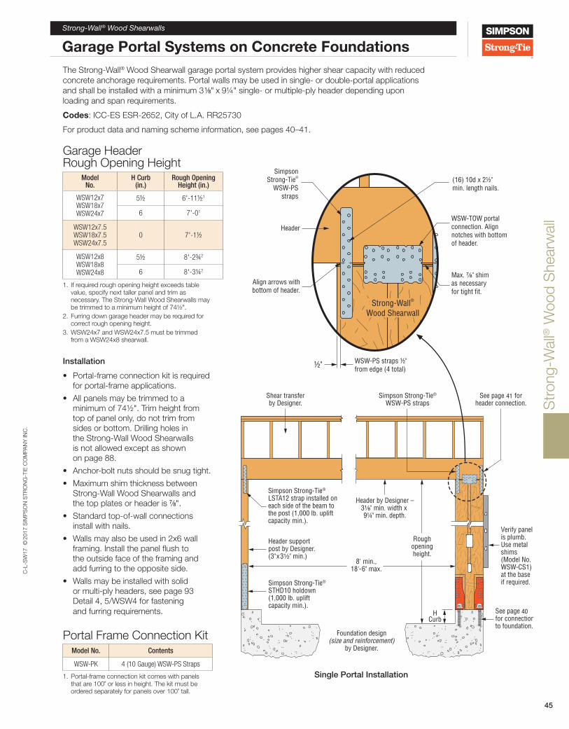
Str
ong-
Wal
l® W
ood
She
arw
all
C-L
-SW
17 ©
2017
SIM
PS
ON
STR
ON
G-T
IE C
OM
PAN
Y IN
C.
Strong-Wall® Wood Shearwalls
45
Garage Portal Systems on Concrete FoundationsThe Strong-Wall® Wood Shearwall garage portal system provides higher shear capacity with reduced concrete anchorage requirements. Portal walls may be used in single- or double-portal applications and shall be installed with a minimum 3 1/8" x 9¼" single- or multiple-ply header depending upon loading and span requirements.
Codes: ICC-ES ESR-2652, City of L.A. RR25730
For product data and naming scheme information, see pages 40–41.
Installation
• Portal-frame connection kit is required for portal-frame applications.
• All panels may be trimmed to a minimum of 74½". Trim height from top of panel only, do not trim from sides or bottom. Drilling holes in the Strong-Wall Wood Shearwalls is not allowed except as shown on page 88.
• Anchor-bolt nuts should be snug tight.
• Maximum shim thickness between Strong-Wall Wood Shearwalls and the top plates or header is 7/8".
• Standard top-of-wall connections install with nails.
• Walls may also be used in 2x6 wall framing. Install the panel flush to the outside face of the framing and add furring to the opposite side.
• Walls may be installed with solid or multi-ply headers, see page 93 Detail 4, 5/WSW4 for fastening and furring requirements.
Garage Header Rough Opening Height
Model No.
H Curb (in.)
Rough Opening Height (in.)
WSW12x7WSW18x7WSW24x7
5½ 6'-11½1
6 7'-01
WSW12x7.5WSW18x7.5WSW24x7.5
0 7'-1½
WSW12x8WSW18x8WSW24x8
5½ 8'-2¾2
6 8'-3¼2
1. If required rough opening height exceeds table value, specify next taller panel and trim as necessary. The Strong-Wall Wood Shearwalls may be trimmed to a minimum height of 74½".
2. Furring down garage header may be required for correct rough opening height.
3. WSW24x7 and WSW24x7.5 must be trimmed from a WSW24x8 shearwall.
Portal Frame Connection KitModel No. Contents
WSW-PK 4 (10 Gauge) WSW-PS Straps
1. Portal-frame connection kit comes with panels that are 100" or less in height. The kit must be ordered separately for panels over 100" tall.
Single Portal Installation
Shear transferby Designer.
Verify panelis plumb.Use metal shims(Model No.WSW-CS1)at the baseif required.
Header support post by Designer.(3"x3½" min.)
Foundation design(size and reinforcement)
by Designer.
Simpson Strong-Tie®
STHD10 holdown(1,000 lb. uplift capacity min.).
Header by Designer –3⅛" min. width x 91/4" min. depth.
Simpson Strong-Tie®
LSTA12 strap installed oneach side of the beam tothe post (1,000 lb. upliftcapacity min.).
See page 10for connectionto foundation.
Simpson Strong-Tie®
WSW-PS strapsSee page 11 for
header connection.
8' min.,18'-6" max.
Roughopeningheight.
HCurb
Header
Align arrows withbottom of header.
½" WSW-PS straps ½"from edge (4 total)
SimpsonStrong-Tie®
WSW-PSstraps
(16) 10d x 2½"min. length nails.
WSW-TOW portalconnection. Alignnotches with bottomof header.
Max. ⅞" shimas necessaryfor tight fit.
Strong-Wall®
Wood Shearwall
40
41

Str
ong-
Wal
l® W
ood
She
arw
all
C-L
-SW
17 ©
2017
SIM
PS
ON
STR
ON
G-T
IE C
OM
PAN
Y IN
C.
46
Strong-Wall® Wood Shearwalls
Garage Portal Systems on Concrete Foundations
Portal Design InformationA portal frame under lateral loads causes the portal header to experience internal stresses in addition to those created by the primary loads (live, dead and snow). These additional stresses are called induced forces and must be considered when designing portal headers. To account for the induced forces from lateral loads, a concentrated end moment equal to the top-of-panel moment must be placed at the end of the header that is connected to the WSW panel. For WSW12 and WSW18 panels, the moment induced into the portal header must be taken as 20% and 10%, respectively, of the total lateral moment at the base. The total lateral moment is calculated as the design shear times the panel height. For headers with typical residential uniform loads, the induced moment and shear forces from a portal-frame system do not control the design. This is due to the 1.60 load duration factor (CD) used in design and the induced stresses from wind and seismic loads.
The lateral and vertical loads shown on page 47 for portal frames assume that the header size falls within the portal-frame parameters listed in the table.
Alternative Garage Front OptionsThese alternative garage-front options may be used for applications when the Strong-Wall® Wood Shearwall is installed at the full height (option 1) or without the additional Portal-Frame Kit (option 2), when higher capacity or reduced concrete anchorage is not needed. Refer to the Standard Application on Concrete Foundations on pages 42–44 for product data and allowable load values.
For Garage Wall Option 2, the Designer shall design for:1. Shear transfer2. Out-of-plane loading effect3. Increased overturning and drift due to additional height
Strong-Wall® Wood Shearwall Portal Header Design Parameters
Header Design Parameter Allowable Range
Width 3 1/8" – 5 ½"
Depth 9 ¼" – 18"
Clear Span 8' – 18' 6"
K 90 lb./in. – 4,000 lb./in.
1. Single- or multiple-ply header members may be used.2. Secondary moment, shear and axial forces shall be
considered in header design. 3. Header design shall be by Designer and assume gravity
loads only induce simple span moments in beam. 4. Header stiffness (K) for use in WSW portal system
may be determined using the following equation: K = (E x b x d3) / 12L3 where: E = Header modulus of elasticity (psi) b = Header width (in.) d = Header depth (in.) L = Header clear span (in.)
See page 41 for top plate connection
Shear transferby Designer
Header by Designer —3⅛" min. width x 9¼" min. depth.
8' min.,18'-6" max.
Header support post by Designer Rough
openingheight
HCurb
See pages 41 and 45 for header
connection
Column base detail by Designer (not shown)(1,000 lb. uplift capacity min.)
Foundation design(size and reinforcement)
by Designer
Alternate Garage Front Option 1
Alternate Garage Front Option 2

Str
ong-
Wal
l® W
ood
She
arw
all
C-L
-SW
17 ©
2017
SIM
PS
ON
STR
ON
G-T
IE C
OM
PAN
Y IN
C.
47
Strong-Wall® SB Shearwalls
Garage Portal Systems on Concrete Foundations
Strong-Wall® Wood Shearwall Single-Wall Garage Portal System on Concrete Foundation
Strong-Wall Wood Shearwall
Model
Allowable Vertical Load, P
(lb.)5
2,500 psi Concrete 3,000 psi Concrete
Seismic3 Wind Seismic3 Wind
Allowable ASD Shear
Load, V (lb.)
Drift at Allowable Shear, Δ
(in.)9
Anchor Tension at Allowable Shear, T
(lb.)10
Allowable ASD Shear
Load, V (lb.)
Drift at Allowable Shear, Δ
(in.)9
Anchor Tension at Allowable Shear, T
(lb.)10
Allowable ASD Shear
Load, V (lb.)
Drift at Allowable Shear, Δ
(in.)9
Anchor Tension at Allowable Shear, T
(lb.)10
Allowable ASD Shear
Load, V (lb.)
Drift at Allowable Shear, Δ
(in.)9
Anchor Tension at Allowable Shear, T
(lb.)10
WSW12x7
1,000 1,645 0.38 12,750 2,135 0.53 16,525 1,645 0.38 12,750 2,135 0.53 16,525
4,000 1,645 0.38 12,750 1,955 0.49 15,150 1,645 0.38 12,750 2,135 0.53 16,525
7,500 1,645 0.38 12,750 1,730 0.43 13,370 1,645 0.38 12,750 2,100 0.52 16,255
WSW18x7
1,000 3,225 0.38 16,235 3,310 0.42 16,675 3,225 0.38 16,235 3,350 0.43 16,880
4,000 3,225 0.38 16,235 3,010 0.38 15,160 3,225 0.38 16,235 3,350 0.43 16,880
7,500 3,225 0.38 16,235 2,660 0.34 13,395 3,225 0.38 16,235 3,230 0.41 16,280
WSW12x7.5
1,000 1,520 0.41 12,900 1,965 0.57 16,670 1,520 0.41 12,900 1,970 0.57 16,720
4,000 1,520 0.41 12,900 1,785 0.51 15,150 1,520 0.41 12,900 1,970 0.57 16,720
7,500 1,520 0.41 12,900 1,575 0.45 13,370 1,520 0.41 12,900 1,915 0.55 16,255
WSW18x7.5
1,000 2,955 0.41 16,300 3,020 0.45 16,675 2,955 0.41 16,300 3,350 0.50 18,500
4,000 2,955 0.41 16,300 2,745 0.41 15,160 2,955 0.41 16,300 3,270 0.48 18,045
7,500 2,945 0.41 16,260 2,425 0.36 13,395 2,955 0.41 16,300 2,950 0.44 16,280
WSW12x8
1,000 1,310 0.44 12,110 1,695 0.60 15,690 1,310 0.44 12,110 1,695 0.60 15,690
4,000 1,310 0.44 12,110 1,635 0.58 15,150 1,310 0.44 12,110 1,695 0.60 15,690
7,500 1,310 0.44 12,110 1,445 0.51 13,370 1,310 0.44 12,110 1,695 0.60 15,690
WSW18x8
1,000 2,610 0.44 15,730 2,770 0.49 16,675 2,610 0.44 15,730 3,250 0.58 19,560
4,000 2,610 0.44 15,730 2,520 0.45 15,160 2,610 0.44 15,730 2,995 0.53 18,045
7,500 2,610 0.44 15,730 2,225 0.40 13,395 2,610 0.44 15,730 2,705 0.48 16,280
1. Allowable shear loads are applicable to installations on concrete with specified compressive strengths as listed using the ASD basic (IBC Section 1605.3.1) or the alternative basic (IBC Section 1605.3.2) load combinations.
2. Load values include evaluation of bearing stresses on concrete foundations and do not require further evaluation by the Designer. For installations on masonry foundations, bearing capacity shall be evaluated by the Designer.
3. Seismic design based on 2015 IBC using R = 6.5. For other codes, use the seismic coefficients corresponding to light-frame bearing walls with wood structural panels or sheet-steel panels.
4. Allowable values shown apply to Single-Wall Garage Portal Systems. The allowable shear load for a Double-Wall Garage Portal System, which consists of two walls with a header continuous across both panels, may be taken as twice the table value.
5. Allowable vertical load denotes the total maximum concentric vertical load permitted on the panel acting in combination with the allowable shear loads.
6. Allowable shear, drift and anchor tension values may be interpolated for intermediate height or vertical loads. For panels 74½"–78" tall, use the values for a 78"-tall panel.
7. High-strength anchor bolts are required for anchor tension forces exceeding the allowable load for standard-strength bolts tabulated on pages 53–54. See pages 52–59 for WSW-AB anchor bolt information and anchorage solutions.
8. See page 44 for allowable out-of-plane and axial capacities. 9. Drifts at lower design shear may be linearly reduced. 10. Tabulated anchor tension values assume no resisting vertical load. Anchor tension loads at design shear values
and including the effect of vertical load may be determined using the following equation: T = [(k x V x H) / B] – P/2, where:
T = Anchor tension load (lb.) V = Design shear load (lb.) P = Applied vertical load (lb.) H = Panel height (in.) B = Moment arm (in.); 8.06" for WSW12, 13.94" for WSW18 k = Portal factor; 0.80 for WSW12 panels 93¼" or less in height, 0.90 for WSW18 panels 93¼" or less in height, 1.00 for all other panels.

Str
ong-
Wal
l® W
ood
She
arw
all
C-L
-SW
17 ©
2017
SIM
PS
ON
STR
ON
G-T
IE C
OM
PAN
Y IN
C.
48
Strong-Wall® Wood Shearwalls
Two-Story Stacked on Concrete FoundationsThe same Strong-Wall® Wood Shearwall models used for standard applications on concrete may be used in stacked wall applications. See Product data tables below for models that may be used in this application.
Codes: ICC-ES ESR-2652, City of L.A. RR 25730
For product naming scheme information, see page 41.
Two-Story Stacked WSW Product Data — Upper Wall
Model No. W (in.)
H (in.)
Total Wall Weight
(lb.)
WSW18x9 18 105¼ 185
WSW24x9 24 105¼ 245
WSW18x10 18 117¼ 205
WSW24x10 24 117¼ 270
WSW18x11 18 129¼ 220
WSW24x11 24 129¼ 295
WSW18x12 18 141¼ 240
WSW24x12 24 141¼ 320
1. Order WSW-MSKXXKT separately for two-story stacked applications. 2. See product data table on page 40 for footnotes.3. The width of the upper wall should match the width of the lower wall.
Two-Story Stacked WSW Product Data — Bottom Wall
Model No. W (in.)
H (in.)
Anchor Bolts Total Wall Weight
(lb.)Qty. Dia. (in.)
WSW18x8 18 93¼ 2 7/8 165
WSW24x8 24 93¼ 2 1 225
WSW18x9 18 105¼ 2 7/8 185
WSW24x9 24 105¼ 2 1 245
WSW18x10 18 117¼ 2 7/8 205
WSW24x10 24 117¼ 2 1 270
WSW18x11 18 129¼ 2 7/8 220
WSW24x11 24 129¼ 2 1 295
WSW18x12 18 141¼ 2 7/8 240
WSW24x12 24 141¼ 2 1 320
1. See product data table on page 40 for footnotes.
Multi-Story Connection KitModel No. Contents
WSW-MSK18KT (2) Holdowns with preattached bolts(2) Standard hex nuts and flat washers
(1) LSL bearing blockInstallation instructionsWSW-MSK24KT
Two-Story Stacked Installation
Second-story panelheight includes wallheight plus totalfloor depth
Strong-Wall®Wood Shearwall
Foundation design(size and
reinforcement)by Designer
WSW-AB
MSK connection kitModel WSW-MSKXXKT
(order separately)

Str
ong-
Wal
l® W
ood
She
arw
all
C-L
-SW
17 ©
2017
SIM
PS
ON
STR
ON
G-T
IE C
OM
PAN
Y IN
C.
49
Strong-Wall® SB Shearwalls
Two-Story Stacked on Concrete Foundations
Foundation design(size and
reinforcement)by Designer.
See page 10 forconnection tofoundation.
See page 11 fortop-plate connection.
Two-Story Stacked Installation
First-Story Installation with Wood Floor System
Specify panel height from top of foundation to underside of top plates.
2x6 Framing InstallationAlternative top connection recommended.
See pages 85 and 90 for details.
2x6 Framing InstallationCut slots (¼" wide max.) in the top plates to allow the MSK holdown
to pass through. Do not notch the double top plates.
Two-Story Stacked MSK Connection Details
Hex nuts and structuralwashers providedwith MSK kit. Nuts require a snug tight fit.
MSK holdowninstalls with
10d x 2½" min.length nails
(fill all holes).
Align LSLbearing block
with first-storypanel.
See page 11 fortop-plate connection.
Installation
• All panels may be trimmed to a minimum of 74½". Trim height from top of panel only, do not trim from sides or bottom. Drilling holes in the Strong-Wall® Wood Shearwalls is not allowed except as shown on page 88.
• Anchor-bolt nuts should be snug tight.• Maximum shim thickness between
the shearwall and the top plates or header is 7/8".
• Walls may also be used in 2x6 wall framing. Install the panel flush to the outside face of the framing and add furring to the opposite side.
• Standard top-of-wall connections install with nails.
• The second-story panel must be the same width as the first-story panel.
• When specifying the height of the second-story panels, add the total floor height, including sheathing, to the wall height, then subtract 2". See h 3 definition on page 51.
40
41

Str
ong-
Wal
l® W
ood
She
arw
all
C-L
-SW
17 ©
2017
SIM
PS
ON
STR
ON
G-T
IE C
OM
PAN
Y IN
C.
50
Strong-Wall® Wood Shearwalls
Two-Story Stacked on Concrete Foundations
Strong-Wall® Wood Shearwall First-Story Walls — Stacked Application on Concrete Foundation9,11
Model No.
Allowable Vertical Load, P
(lb.)4
Stiffness Factor, Kx109
(lb.-in.2)
2,500 psi Concrete 3,000 psi Concrete
Seismic3 Wind Seismic3 Wind
Allowable ASD Base Moment (lb.-in.)
Anchor Tension at
Allowable ASD Base Moment
(lb.)10
Allowable ASD Base Moment (lb.-in.)
Anchor Tension at
Allowable ASD Base Moment
(lb.)10
Allowable ASD Base Moment (lb.-in.)
Anchor Tension at
Allowable ASD Base Moment
(lb.)10
Allowable ASD Base Moment (lb.-in.)
Anchor Tension at
Allowable ASD Base Moment
(lb.)10
WSW18x8 4,000 9.7 206,550 14,820 184,730 13,255 206,550 14,820 218,020 15,645
WSW24x8 4,000 19.4 413,565 21,840 423,540 22,365 413,565 21,840 455,060 24,030
WSW18x9 4,000 10.3 200,500 14,385 184,715 13,255 200,500 14,385 217,975 15,640
WSW24x9 4,000 21.5 411,000 21,705 423,525 22,365 411,000 21,705 452,050 23,870
WSW18x10 4,000 11.6 202,255 14,510 184,670 13,250 202,255 14,510 217,970 15,640
WSW24x10 4,000 22.6 389,855 20,585 423,505 22,365 389,855 20,585 429,135 22,660
WSW18x11 4,000 12.5 197,755 14,190 184,700 13,250 197,755 14,190 217,785 15,625
WSW24x11 4,000 24.8 389,045 20,545 423,550 22,365 389,045 20,545 428,465 22,625
WSW18x12 4,000 12.8 189,275 13,580 184,755 13,255 189,275 13,580 208,345 14,950
WSW24x12 4,000 26.5 380,670 20,100 418,805 22,115 380,670 20,100 418,805 22,115
Strong-Wall® Wood Shearwall Second-Story Walls — Stacked Application on Concrete Foundation6,7
Model No. Allowable
Vertical Load, P (lb.)4
Seismic3 Wind
Allowable ASD Shear Load, V
(lb.)
Drift at Allowable Shear, Δ
(in.)
Allowable ASD Shear Load, V
(lb.)
Drift at Allowable Shear, Δ
(in.)
WSW18x9 2,000 1,225 0.42 1,345 0.48
WSW24x9 2,000 2,165 0.41 2,380 0.46
WSW18x10 2,000 1,125 0.47 1,235 0.53
WSW24x10 2,000 1,990 0.46 2,190 0.52
WSW18x11 2,000 1,020 0.52 1,120 0.59
WSW24x11 2,000 1,815 0.51 1,995 0.59
WSW18x12 2,000 920 0.57 1,010 0.64
WSW24x12 2,000 1,640 0.57 1,805 0.65
See notes below.
1. Allowable ASD base moments and anchor tension values are applicable to installations on concrete with specified compressive strengths as listed using the ASD basic (IBC Section 1605.3.1) or the alternative basic (IBC Section 1605.3.2) load combinations.
2. Load values include evaluation of bearing stresses on concrete foundations and do not require further evaluation by the Designer. For installations on masonry foundations, bearing capacity shall be evaluated by the Designer.
3. Seismic design based on 2015 IBC using R = 6.5. For other codes, use the seismic coefficients corresponding to light-frame bearing walls with wood structural panels or sheet-steel panels.
4. Allowable vertical load denotes the total maximum vertical load permitted on the panel acting in combination with the allowable shear load and base moment.
5. Allowable shear, drift, base moment and anchor tension values may be interpolated for intermediate height or vertical loads.
6. Two-story stacked panel combinations may consist of any height combination of equal width panels listed in these tables.
7. A multi-story kit (MSK) is required to attach the second-story panel to the first-story panel.
8. High-strength anchor bolts are required for anchor tension forces exceeding the allowable load for standard-strength bolts tabulated on pages 53–54. See pages 52–59 for WSW-AB anchor bolt information and anchorage solutions.
9. The Designer must verify that the cumulative overturning moment at the base of the first-story panel does not exceed the allowable base moment
capacity as shown in the example on page 51. The overturning base moment shall be determined using the following equation: MOT = (V1 x h1) + (V2 x h2), where: MOT = Overturning base moment (lb.- in.) V1 = Applied shear load to first-story panel (lb.) V2 = Applied shear load to second-story panel (lb.) h1 = Height of first-story panel (in.); h2 = Total assembly Height (h1 + Height of second-story panel + 5) (in.)
Tabulated anchor tension values assume no resisting vertical load. Anchor tension loads at design shear values and including the effect of vertical load may be determined using the following equation: T = MOT / B – P/2, where: T = Anchor tension load (lb.) P = Applied vertical load (lb.) MOT = Overturning moment (lb.- in.), see Footnote 9 B = Moment arm (in.); 13.94" for WSW18, 18.94" for WSW24
10. First-story panel drift must comply with code drift limits; evaluate drift at the top of the first-story panel using the following equation: Δ = h1
2 / K x [(3 x V2 x h3) + (2 x Vbase x h1)], where: Δ = First-story panel drift (in.) K = Stiffness factor for first-story panel (lb.- in.2) h1 = First-story panel height (in.) h3 = Second-story panel height (in.) V2 = Applied shear load to second-story panel (lb.) Vbase = Sum of applied shear loads to first-story panel and second-story panel. (lb.)

Str
ong-
Wal
l® W
ood
She
arw
all
C-L
-SW
17 ©
2017
SIM
PS
ON
STR
ON
G-T
IE C
OM
PAN
Y IN
C.
Strong-Wall® Wood Shearwalls
51
Two-Story Stacked on Concrete Foundations
Designing for Cumulative Overturning ForcesIn multi-story structures, shear and the associated overturning forces due to seismic and wind requirements must be carried down to the foundation by the building’s lateral-force resisting system. These forces are cumulative over the height of the building, and shear forces applied at the second or third levels of a structure will generate much larger base overturning moments than the same shears applied at the first story. If cumulative overturning is not considered, the design may result in forces several times higher than the capacity of the lower wall, anchor bolts and foundation anchorage.
When specifying two-story stacked applications, analysis should be performed by following these steps.
1. Analyze the structure to determine the shear forces at each floor. The detail to the right illustrates the forces developed in a two-story stacked application. Then calculate the cumulative overturning moment (MOT), based on the story heights and applied shear forces at each story, as follows:
MOT = (V1 x h1) + (V2 x h2)
2. Select the first-story panel and ensure that the allowable base moment exceeds the overturning moment (MOT).
3. Check the applicable second-story panel with the same width as the first-story panel and verify that the allowable second-story shear force exceeds the applied second-story shear force.
4. Check the first-story panel drift.
Drift Equation for First-Story ShearwallsThe first-story panel drift must comply with code drift limits. Evaluate drift at the top of the first-story panel using the following equation:
Δ = (h12)
(3V2h3 + 2Vbaseh1) where: K Δ = First-story panel drift (in.) K = Stiffness factor for first-story panel (lb.-in.2) h1 = First-story panel height (in.) h3 = Second-story panel height (in.) V1 = Applied shear load to first-story panel (lb.) V2 = Applied shear load to second-story panel (lb.) Vbase = V1 + V2 (lb.)
GivenSeismic, f'c = 2,500 psi
First-story wall height = 9 ft.
Second-story wall height = 8 ft.
Joist height = 11 7/8 ft.
First-story panel shear, V1 = 1,200 lb.
Second-story panel shear, V2 = 1,000 lb.
Solution1. Calculate the overturning moment;
MOT = (1,200 lb. x 105.25 in.) + (1,000 lb. x 213.25 in.) = 339,550 lb.-in.
2. Select WSW24x9 at the first-story;
Mallow = 411,000 lb.-in. > MOT OK
3. Check the capacity of the second-story WSW24x9;
Vallow = 2,165 lb. > V2 OK
4. Verify that the first-story drift does not exceed ASD code drift limit,
Δallow = 0.7 (0.025H / Cd) = H / 228.6
Δallow = 105.25 in. / 228.6 = 0.46 in.
Δ =
(105.25")2 [(3 x 1,000 lb. x 103") + (2 x 2,200 lb. x 105.25")]
21.5 x 10⁹
Δ = 0.40 in. < Δallow OK
h1 = 105¼"
h3 = 103"
h2 = 213¼"
WSW24x9
V1 = 1,200 lb.
V2 = 1,000 lb.
WSW24x9
MOT

Str
ong-
Wal
l® W
ood
She
arw
all
C-L
-SW
17 ©
2017
SIM
PS
ON
STR
ON
G-T
IE C
OM
PAN
Y IN
C.
52
Strong-Wall® Wood Shearwalls
Anchorage Solutions
WSW-AB Anchor BoltsWSW-AB anchor bolts in 7/8" and 1" diameters offer flexibility to meet specific project demands. Inspection is easy; the head is stamped with a No-Equal symbol for identification, bolt length, bolt diameter, and optional “HS” for “High Strength” if specified.
Material: ASTM F1554 Grade 36; High Strength (HS) ASTM A449
An additional nut for template installation is provided with each WSW-AB.
Strong-Wall Wood Shearwall
Width (in.)
Model No. Dia. (in.)
Total Length
(in.)
le(in.)
12 and 18
WSW-AB7/8 x 24 7/8 24 20
WSW-AB7/8 x 24HS 7/8 24 20
WSW-AB7/8 x 30 7/8 30 26
WSW-AB7/8 x 30HS 7/8 30 26
WSW-AB7/8 x 36HS 7/8 36 32
24
WSW-AB1x24 1 24 20
WSW-AB1x24HS 1 24 20
WSW-AB1x30 1 30 26
WSW-AB1x30HS 1 30 26
WSW-AB1x36HS 1 36 32
WSW-HSR Extension Kit WSW-HSR allows for anchorage in tall stemwall applications where full embedment of a WSW-AB into the footing is required. The head is stamped for identification like a WSW-AB. Kit includes ASTM A449 high-strength rod with heavy hex nut fixed in place and high-strength coupler nut. Do not use in place of WSW-AB.
Strong-Wall Wood Shearwall
Width (in.)
Model No. Dia. (in.)
Total Length
(in.)
le(in.)
12 and 18WSW-HSR7/8 x 24KT 7/8 24 22
WSW-HSR7/8 x 36KT 7/8 36 34
24WSW-HSR1x24KT 1 24 22
WSW-HSR1x36KT 1 36 34
Total le = WSW-HSR le + WSW-AB le + 2 1/8"
WSW-HSRXXKT
⅞
HX
Heavy hex nutfixed in place
Top ofconcrete
⅞" or 1"High-strength
rod
High-strengthcoupler
nut
Leng
th
le
2⅛"HX onextension
kit
WSW-HSR and WSW-AB
Assembly
WSW-HSR
le
High-strengthcoupler nut
2⅛"
Top ofconcrete
Cut to lengthas necessary
le
WSW-AB
WSW-AB
⅞"
Leng
th
le
Top ofconcrete
Heavy hex nutfixed in place
on all WSW-ABanchor bolts
Heavyhex nut
Heavyhex nut
Plate washer
2⅛"

Str
ong-
Wal
l® W
ood
She
arw
all
C-L
-SW
17 ©
2017
SIM
PS
ON
STR
ON
G-T
IE C
OM
PAN
Y IN
C.
Strong-Wall® Wood Shearwalls
53
Anchorage Solutions
Strong-Wall® Wood Shearwall Tension Anchorage Solutions — 2,500 psi Concrete1,5,6
Design Criteria
Concrete Condition
Anchor Strength2
WSW-AB7/8 Anchor Bolt WSW-AB1 Anchor Bolt
ASD Allowable Tension (lb.)
W (in.)
de (in.)
ASD Allowable Tension (lb.)
W (in.)
de (in.)
Seismic3
Cracked
Standard11,900 27 9 16,100 33 11
13,100 29 10 17,100 35 12
High Strength24,900 43 15 33,000 51 17
27,100 46 16 35,300 54 18
Uncracked
Standard12,500 24 8 15,700 28 10
13,100 25 9 17,100 30 10
High Strength25,300 38 13 32,300 44 15
27,100 40 14 35,300 47 16
Wind4
Cracked
Standard
5,100 14 6 6,200 16 6
8,700 20 7 11,400 24 8
13,100 27 9 17,100 32 11
High Strength
15,900 30 10 21,100 36 12
18,400 33 11 27,300 42 14
23,100 38 13 31,800 46 16
27,100 42 14 35,300 50 17
Uncracked
Standard
5,000 12 6 6,400 14 6
9,300 18 6 12,500 22 8
13,100 23 8 17,100 28 10
High Strength
15,200 25 9 21,900 32 11
19,900 30 10 26,400 36 12
24,000 34 12 31,500 40 14
27,100 37 13 35,300 43 15
Strong-Wall® Wood Shearwall Tension Anchorage Solutions — 3,000 psi Concrete1,5,6
Design Criteria
Concrete Condition
Anchor Strength2
WSW-AB7/8 Anchor Bolt WSW-AB1 Anchor Bolt
ASD Allowable Tension (lb.)
W (in.)
de (in.)
ASD Allowable Tension (lb.)
W (in.)
de (in.)
Seismic3
Cracked
Standard12,300 26 9 16,000 31 11
13,100 28 10 17,100 33 11
High Strength25,200 41 14 32,700 48 16
27,100 43 15 35,300 51 17
Uncracked
Standard12,000 22 8 16,300 27 9
13,100 24 8 17,100 28 10
High Strength25,300 36 12 32,700 42 14
27,100 38 13 35,300 44 15
Wind4
Cracked
Standard
5,000 13 6 5,600 14 6
8,800 19 7 10,200 21 7
13,100 25 9 17,100 30 10
High Strength
15,700 28 10 20,100 33 11
19,200 32 11 25,300 38 13
23,200 36 12 32,300 44 15
27,100 40 14 35,300 47 16
Uncracked
Standard
5,500 12 6 6,200 13 6
8,500 16 6 12,800 21 7
13,100 22 8 17,100 26 9
High Strength
16,600 25 9 21,800 30 10
19,700 28 10 25,200 33 11
24,000 32 11 31,700 38 13
27,100 35 12 35,300 41 14
See footnotes on page 54.
See footnotes on page 54.

Str
ong-
Wal
l® W
ood
She
arw
all
C-L
-SW
17 ©
2017
SIM
PS
ON
STR
ON
G-T
IE C
OM
PAN
Y IN
C.
54
Strong-Wall® Wood Shearwalls
Anchorage Solutions
Strong-Wall® Wood Shearwall Tension Anchorage Solutions — 4,500 psi Concrete1,5,6
Design Criteria
Concrete Condition
Anchor Strength2
WSW-AB7/8 Anchor Bolt WSW-AB1 Anchor Bolt
ASD Allowable Tension (lb.)
W (in.)
de (in.)
ASD Allowable Tension (lb.)
W (in.)
de (in.)
Seismic3
Cracked
Standard12,600 23 8 16,000 27 9
13,100 24 8 17,100 29 10
High Strength24,800 36 12 32,100 42 14
27,100 38 13 35,300 45 15
Uncracked
Standard12,700 20 7 15,700 23 8
13,100 21 7 17,100 25 9
High Strength24,600 31 11 32,500 37 13
27,100 34 12 35,300 39 13
Wind4
Cracked
Standard
5,400 12 6 6,800 14 6
8,300 16 6 11,600 20 7
13,100 22 8 17,100 26 9
High Strength
15,300 24 8 21,400 30 10
19,300 28 10 25,800 34 12
23,600 32 11 31,000 38 13
27,100 36 12 35,300 42 14
Uncracked
Standard
6,800 12 6 6,800 12 6
9,400 15 6 12,400 18 6
13,100 19 7 17,100 23 8
High Strength
16,800 22 8 21,600 26 9
20,300 25 9 26,700 30 10
24,100 28 10 32,200 34 12
27,100 31 11 35,300 36 12
1. Anchorage designs conform to ACI 318-14 and ACI 318-11 Appendix D with no supplementary reinforcement for cracked and uncracked concrete as noted.
2. Anchor strength indicates required grade of WSW-AB anchor bolt. Standard (ASTM F1554 Grade 36) or high strength (HS) (ASTM A449).
3. Seismic indicates Seismic Design Categories C through F. Detached one- and two-family dwellings in SDC C may use wind anchorage solutions. Seismic anchorage designs conform to ACI 318-14 Section 17.2.3.4.3 and ACI 318-11 Section D.3.3.4.
4. Wind includes Seismic Design Categories A and B and detached one- and two-family dwellings in SDC C.5. Foundation dimensions are for anchorage only. Foundation design (size and reinforcement) by others.
The registered design professional may specify alternative embedment, footing size or anchor bolt.6. Refer to slab on grade, curb, stemwall and interior footing details for w and de as shown on pages 56–57.

Str
ong-
Wal
l® W
ood
She
arw
all
C-L
-SW
17 ©
2017
SIM
PS
ON
STR
ON
G-T
IE C
OM
PAN
Y IN
C.
Strong-Wall® Wood Shearwalls
55
Anchor Bolt Solutions
Strong-Wall® Wood Shearwall Shear Anchorage Foundation shear reinforcement to resist shear forces from Strong-Wall® Wood Shearwalls located at the edge of concrete is shown in the table below. The WSW12 used in wind applications does not require shear reinforcement when the panel design shear force is less than the anchorage allowable shear load shown in the table below.
Hairpin Shear Reinforcement
#3 hairpingrade 60 rebar
(min.)
WSW-AB
Lh min.
3"
Field tie and secure during concrete placement. Overlap
varies with bolt spacing.
Tie Shear Reinforcement
#3 tiegrade 60
rebar (min.)
WSW-AB
Lt
3"
4" min.
Field tie and secureduring concrete
placement.
Hairpin Installation(Garage curb shown, other footing types similar)
#3 hairpin (#3 tie similar),see table for required quantity.
1½" CLR
WSW-AB
Strong-Wall® Wood Shearwall Shear Anchorage Solutions
Strong-Wall Wood Shearwall
Model
Lt or Lh (in.)
Seismic3 Wind4
Shear Reinforcement
Minimum Curb/Stemwall Width
(in.)
Shear Reinforcement
Minimum Curb/Stemwall Width
(in.)
ASD Allowable Shear Load, V (lb.)6
Uncracked Cracked
WSW12 10 1⁄4 (1) #3 Hairpin 85 See Note 6 6 1,035 740
WSW18 15 (1) #3 Hairpin 85 (1) #3 Hairpin 6 Hairpin reinforcement achieves maximum allowable shear load of the
Strong-Wall® WSW.WSW24 19 (2) #3 Hairpin 85 (1) #3 Hairpin 6
1. Shear anchorage designs conform to ACI 318-14 and assume minimum 2,500 psi concrete. See pages 53–54 for tension anchorage.2. Shear reinforcement is not required for interior foundation applications (panel installed away from edge of concrete), or braced-wall panel applications.3. Seismic indicates Seismic Design Categories C through F. Detached one- and two-family dwellings in SDC C may use wind anchorage solutions.
Seismic shear reinforcement designs conform to ACI 318-14 Section 17.2.3.5.3.4. Wind includes Seismic Design Categories A and B.5. Minimum curb/stemwall width is 6" when standard-strength anchor bolt is used.6. Use (1) #3 tie for WSW12 when panel design shear force exceeds tabulated anchorage allowable shear load.7. #4 grade 40 shear reinforcement may be substituted for WSW shear anchorage solutions.8. The registered design professional may specify alternative shear anchorage.

Str
ong-
Wal
l® W
ood
She
arw
all
C-L
-SW
17 ©
2017
SIM
PS
ON
STR
ON
G-T
IE C
OM
PAN
Y IN
C.
56
Strong-Wall® Wood Shearwalls
Footing PlanBrick Ledge Section View
Anchorage Solutions General Notes1. The Designer may specify alternate embedment, footing size or bolt grade.2. Footing dimensions and rebar requirements are for anchorage only.
Curb or Stemwall Installation
Slab-on-Grade Installation
Brick Ledge Installation
Perspective View
Perspective View
Foundation design (size and reinforcement) by Designer.
Shear reinforcementper page 25 when required.
Minimum curb/stemwallwidth per page 25.
WSW-AB
H
de
2⅛"
W
½ W ½ W5" min. for WSW-AB⅞6" min. for WSW-AB1.
Slab-on-Grade Section View
Shear reinforcementper page 25 when required.
WSW-AB
H
de
W
½ W ½ W5" min. for WSW-AB⅞6" min. for WSW-AB1.
2⅛"
½W ½WB
½W
½W
W
Perspective View(Slab not shown for clarity)
Curb or Stemwall Section View
Shear reinforcementper page 25 when required.
Minimum curb/stemwallwidth per page 25.
WSW-AB
H
de
2⅛"
W
½ W ½ W5" min. for WSW-AB⅞6" min. for WSW-AB1.
Footing Plan
½W ½WB
½W
½W
W
½W ½WB
½W
½W
W
Footing Plan
Anchorage Solutions
55
55
55
55
55

Str
ong-
Wal
l® W
ood
She
arw
all
C-L
-SW
17 ©
2017
SIM
PS
ON
STR
ON
G-T
IE C
OM
PAN
Y IN
C.
Strong-Wall® Wood Shearwalls
57
Anchorage Solutions General Notes1. The Designer may specify alternate embedment, footing size or bolt grade.2. Footing dimensions and rebar requirements are for anchorage only.
Strong-Wall® Wood Shearwall Anchor Bolt Layout
WallModel
Distance from Centerto Center of WSW-ABs
B (in.)
WSW12 8 1/8
WSW18 14
WSW24 20
de
WSW-AB
W
½ W ½ W5" min. for WSW-AB⅞6" min. for WSW-AB1.
2⅛"
Interior Section View
Interior Installation Stemwall Extension Installation
WSW-AB
Minimum stemwall width per page 55.
WSW-HSR
Stemwallheight =
(WSW-AB le +WSW-HSR le +
2⅛"- de)See page 22 forle dimensions.
Shear reinforcementper page 55 when required.
½ W min. ½ W min.
W
de
2⅛"
5" min. for WSW-AB⅞6" min. for WSW-AB1.
Section at StemwallWSW-AB and WSW-HSR
Extension Application
WSW Plan ViewAnchorage Graphic
3½"13/4"
2" B
½W B ½W
½W
½W
W
Footing Plan
Anchor Solutions

Str
ong-
Wal
l® W
ood
She
arw
all
C-L
-SW
17 ©
2017
SIM
PS
ON
STR
ON
G-T
IE C
OM
PAN
Y IN
C.
58
Strong-Wall® Wood Shearwalls
Grade-Beam Testing
Anchor Reinforcement Solutions on Grade BeamsSimpson Strong-Tie now provides grade-beam anchorage solutions for the Strong-Wall® Wood Shearwall (WSW), which have been calculated to conform to ACI 318-14. Through funding from the Structural Engineers Association of Northern California, initial testing at Scientific Construction Laboratories Inc. confirmed the need to comply with ACI 318 requirements to prevent plastic hinging at anchor locations. Follow-up testing at the Simpson Strong-Tie Tyrell Gilb Research Laboratory was then used to confirm these findings and validate performance. The testing consisted of specimens with closed-tie anchor reinforcement, specimens with non-closed u-stirrups, and control specimens without anchor reinforcement. Flexural and shear reinforcement were designed to resist amplified anchorage forces and compared to test beams designed for non-amplified strength level forces. The test program has proven the performance of the anchor reinforcement details developed by Simpson Strong-Tie.
Significant Findings from Testing:Grade-beam flexural and shear capacity is critical to anchor performance and must be designed to exceed the demands created by the attached structure. In wind load applications, this demand includes the factored demand from the Strong-Wall Wood Shearwall (WSW). In seismic applications, testing and analysis have shown that in order to achieve the anchor performance expected by ACI 318 anchorage design methodologies, the concrete member design strength needs to resist the amplified anchor design demand from ACI 318-14 Section 17.2.3.4.3 and ACI 318-11 Appendix D Section D.3.3.4.3. To help Designers achieve this, Simpson Strong-Tie recommends Designers apply the seismic design moment listed in the table below at the WSW location when evaluating the grade-beam design strength under seismic loads. The tabulated moment correlates to the lowest of the anchor-tension design limits defined in the sections listed above as they relate to each WSW model.
Closed-tie anchor reinforcement is critical to maintain the integrity of the reinforced core where the anchor is located. Testing with u-stirrups that did not include complete closed ties showed premature splitting failure of the grade beam.
Strong-Wall® Wood Shearwall Grade-Beam Anchorage Solutions
Strong-Wall Wood Shearwall
Model
Anchor Bolt Model No.
Anchor Diameter
(in.)
Anchor Reinforcement for Wind and Seismic3,8,9
Amplified LRFD Applied Design Seismic Moment (ft.-lb.)4,5,6,7
Standard-Strength WSW-AB
High-Strength WSW-ABHS
Standard-Strength WSW-AB
High-Strength WSW-ABHS
WSW12WSW-AB7/8
WSW-AB7/8HS 7/8(4) #4
Closed Ties / Wall(6) #4
Closed Ties / Wall
24,700 24,700
WSW18 44,100 50,600
WSW24 WSW-AB1 WSW-AB1HS 1 (2) #4
Closed Ties / Anchor(4) #4
Closed Ties / Anchor 75,600 93,600
1. Anchor reinforcement conforms to ACI 318-14 Section 17.4.2.9 and ACI 318-11 Section D.5.2.9. Full-scale testing was used to validate anchor reinforcement configuration and placement.
2. Minimum concrete compressive strength, f'c = 2,500 psi.3. Closed-tie anchor reinforcement to be ASTM A615 Grade 60 (min.) #4 rebar.4. Grade-beam longitudinal and tie reinforcement shall be specified by the
registered design professional for flexure and shear loading. Design should consider project-specific design loads and allowable soil pressure.
5. Simpson Strong-Tie recommends using the tabulated minimum amplified LRFD applied seismic design moment to ensure grade-beam design flexure and shear strength is adequate to prevent plastic hinge formation under demands associated with anchorage forces corresponding to ACI 318-14 Section 17.2.3.4.3 and ACI 318-11 Section D.3.3.4.3.
6. Designer may use reduced moment due to applied WSW lateral load. Minimum moment shall be the lesser of the tabulated moment or the amplified LRFD design moment for seismic: (ASD design demand shear/0.7) x Ωo x WSW wall height for grade-beam design.
7. Minimum grade-beam design moment for wind and seismic in Seismic Design Category A and B and detached one- and two-family dwellings in SDC C: (ASD design demand shear/0.6) x WSW wall height.
8. Closed tie may be single-piece hoop or two-piece assembly with a u-stirrup with standard 135° hooks and a top cross-tie cap. See detail 6/WSW1.1.
9. See details for grade-beam anchor reinforcement placement, installation and spacing requirements. Closed-tie anchor reinforcement quantity is per wall for the 12"- and 18"-wall models, and per anchor for the 24" model.
Anchorage Solutions

Str
ong-
Wal
l® W
ood
She
arw
all
C-L
-SW
17 ©
2017
SIM
PS
ON
STR
ON
G-T
IE C
OM
PAN
Y IN
C.
Strong-Wall® Wood Shearwalls
59
WSW-RT Exterior Installation*U.S. Patent 7,445,192
Top of concrete WSW-RTPF
(Panel form)U.S. Patent 7,445,192
*WSW-RT templates are reversible. Use the same template for interior or exterior applications.
WSW-RTBL(Brick ledge)
U.S. Patent 7,445,192
WSW-RT Interior Installation*U.S. Patent 7,445,192
An additional nut for template installation is provided
with each WSW-AB.
2⅛"
2⅛" 1½"
Anchor Bolt Height
Simpson Strong-Tie has developed a reusable anchor-bolt template for common foundation types for the Strong-Wall® Wood Shearwalls. The templates help to accurately locate the newly-designed WSW-AB preassembled anchor bolts, which simplifies installation and greatly reduces the chances of voids in the concrete.
Strong-Wall® Wood Shearwall Anchor-Bolt Templates
Strong-Wall Wood Shearwall
Model No.
Width (in.)
Strong-Wall Wood Shearwall Template Model
Reversible Panel Form Brick Ledge
WSW12 12 1/8 WSW-RT12 WSW-RTPF12 WSW-RTBL12
WSW18 18 WSW-RT18 WSW-RTPF18 WSW-RTBL18
WSW24 24 WSW-RT24 WSW-RTPF24 WSW-RTBL24
1. Templates are recommended and are required in some jurisdictions.2. Foundation design by the Designer.
Anchor-Bolt Templates

Anc
hora
ge a
nd In
stal
latio
n D
etai
ls
C-L
-SW
17 ©
2017
SIM
PS
ON
STR
ON
G-T
IE C
OM
PAN
Y IN
C.
60
Simpson Strong-Tie offers
complete structural details in
order to make the specification
and installation easier for
all Strong-Wall® shearwalls.
Versions of these details are
available three ways:
• Full-size 24" x 36" detail sheets may be downloaded at strongtie.com in DWG, DXF and PDF formats.
• Call (800) 999-5099: Full-size, printed sheets may be requested from our regional branches at no charge.
• In this catalog: Smaller versions are shown here for easy reference. Details are numbered to coincide with full-size sheets, although some have been left out to eliminate redundancy.
In This Section: • Steel Strong-Wall® Anchorage and Installation Details Pages 61–76 (Sheets SSW1, SSW1.1, SSW2, SSW3 and SSW4)
• Strong-Wall® Wood Shearwall, Anchorage and Installation Details Pages 77–93 (Sheets WSW1, WSW1.1, WSW2, WSW3 and WSW4)
Anchorage and Installation Details

Anc
hora
ge a
nd In
stal
latio
n D
etai
ls
C-L
-SW
17 ©
2017
SIM
PS
ON
STR
ON
G-T
IE C
OM
PAN
Y IN
C.
61
Anchorage DetailsSteel Strong-Wall® Shearwalls
STEEL STRONG-WALL® ANCHORAGE TYPICAL SECTIONS 1/SSW1

Anc
hora
ge a
nd In
stal
latio
n D
etai
ls
C-L
-SW
17 ©
2017
SIM
PS
ON
STR
ON
G-T
IE C
OM
PAN
Y IN
C.
62
SSWAB TENSION ANCHORAGE SCHEDULE 2,500 PSI 2/SSW1
Steel Strong-Wall® Shearwalls
Anchorage Details
SEE TABLE BELOW FOR DIMENSIONS
W
SLAB OR CURB ANDSURROUNDING FOUNDATIONNOT SHOWN FOR CLARITY
12 W 1
2 W
12 W
12 W
SIMPSON STEELSTRONG-WALL
FOUNDATION PLAN VIEW
SSWAB
STEEL STRONG-WALL ANCHORAGE SOLUTIONS FOR 2500 PSI CONCRETE
DESIGNCRITERIA
CONCRETECONDITION
ANCHORSTRENGTH
SSWAB 3/4" ANCHOR BOLT SSWAB 1" ANCHOR BOLT
ASDALLOWABLEUPLIFT (lbs)
W (in) de (in)ASD
ALLOWABLEUPLIFT (lbs)
W (in) de (in)
SEISMIC
CRACKED
STANDARD8,800 22 8 16,100 33 119,600 24 8 17,100 35 12
HIGHSTRENGTH
18,500 36 12 33,000 51 17
19,900 38 13 35,300 54 18
UNCRACKED
STANDARD8,800 19 7 15,700 28 109,600 21 7 17,100 30 10
HIGHSTRENGTH
18,300 31 11 32,300 44 15
19,900 33 11 35,300 47 16
WIND
CRACKED
STANDARD5,100 14 6 6,200 16 67,400 18 6 11,400 24 89,600 22 8 17,100 32 11
HIGHSTRENGTH
11,400 24 8 21,100 36 1213,600 27 9 27,300 42 1415,900 30 10 31,800 46 1619,900 35 12 35,300 50 17
UNCRACKED
STANDARD5,000 12 6 6,400 14 67,800 16 6 12,500 22 89,600 19 7 17,100 28 10
HIGHSTRENGTH
12,500 22 8 21,900 32 1114,300 24 8 26,400 36 1217,000 27 9 31,500 40 1419,900 30 10 35,300 43 15
NOTES:1. ANCHORAGE DESIGNS CONFORM TO ACI 318-14 AND ACI 318-11 APPENDIX D WITH NO SUPPLEMENTARY
REINFORCEMENT FOR CRACKED OR UNCRACKED CONCRETE AS NOTED.2. ANCHOR STRENGTH INDICATES REQUIRED GRADE OF SSWAB ANCHOR BOLT. STANDARD (ASTM F1554 GRADE 36) OR
HIGH STRENGTH (HS) (ASTM A449).3. SEISMIC INDICATES SEISMIC DESIGN CATEGORY C THROUGH F. DETACHED 1 AND 2 FAMILY DWELLINGS IN SDC C MAY
USE WIND ANCHORAGE SOLUTIONS. SEISMIC ANCHORAGE DESIGNS CONFORM TO ACI 318-14 SECTION 17.2.3.4.3 ANDACI 318-11 SECTION D.3.3.4.
4. WIND INCLUDES SEISMIC DESIGN CATEGORY A AND B AND DETACHED 1 AND 2 FAMILY DWELLINGS IN SDC C.5. FOUNDATION DIMENSIONS ARE FOR ANCHORAGE ONLY. FOUNDATION DESIGN (SIZE AND REINFORCEMENT) BY
OTHERS. THE REGISTERED DESIGN PROFESSIONAL MAY SPECIFY ALTERNATE EMBEDMENT, FOOTING SIZE ORANCHOR BOLT.
6. REFER TO 1/SSW1 FOR de.

Anc
hora
ge a
nd In
stal
latio
n D
etai
ls
C-L
-SW
17 ©
2017
SIM
PS
ON
STR
ON
G-T
IE C
OM
PAN
Y IN
C.
63
Anchorage DetailsSteel Strong-Wall® Shearwalls
SSWAB TENSION ANCHORAGE SCHEDULE 3,500/4,500 PSI 3/SSW1
STEEL STRONG-WALL ANCHORAGE SOLUTIONS FOR 3500 PSI CONCRETE
DESIGNCRITERIA
CONCRETECONDITION
ANCHORSTRENGTH
SSWAB 3/4" ANCHOR BOLT SSWAB 1" ANCHOR BOLTASD
ALLOWABLEUPLIFT (lbs)
W (in) de (in)ASD
ALLOWABLEUPLIFT (lbs)
W (in) de (in)
SEISMIC
CRACKEDSTANDARD
9,000 20 7 15,700 29 109,600 21 7 17,100 31 11
HIGHSTRENGTH
18,200 32 11 33,000 46 1619,900 34 12 35,300 48 16
UNCRACKEDSTANDARD
8,800 17 6 15,700 25 99,600 19 7 17,100 27 9
HIGHSTRENGTH
18,600 28 10 32,600 40 1419,900 30 10 35,300 42 14
WIND
CRACKED
STANDARD6,000 14 6 7,300 16 67,300 16 6 13,500 24 89,600 20 7 17,100 29 10
HIGHSTRENGTH
11,800 22 8 22,700 34 1213,500 24 8 27,400 38 1317,000 28 10 32,300 42 1419,900 32 11 35,300 45 15
UNCRACKED
STANDARD6,000 12 6 7,500 14 67,500 14 6 12,800 20 79,600 17 6 17,100 25 9
HIGHSTRENGTH
12,800 20 7 21,300 28 1014,800 22 8 26,000 32 1116,900 24 8 31,300 36 1219,900 27 9 35,300 39 13
STEEL STRONG-WALL ANCHORAGE SOLUTIONS FOR 4500 PSI CONCRETE
DESIGNCRITERIA
CONCRETECONDITION
ANCHORSTRENGTH
SSWAB 3/4" ANCHOR BOLT SSWAB 1" ANCHOR BOLTASD
ALLOWABLEUPLIFT (lbs)
W (in) de (in)ASD
ALLOWABLEUPLIFT (lbs)
W (in) de (in)
SEISMIC
CRACKEDSTANDARD
8,700 18 6 16,000 27 99,600 20 7 17,100 29 10
HIGHSTRENGTH
17,800 29 10 32,100 42 1419,900 32 11 35,300 45 15
UNCRACKEDSTANDARD
9,100 16 6 15,700 23 89,600 17 6 17,100 25 9
HIGHSTRENGTH
17,800 25 9 32,500 37 1319,900 27 9 35,300 39 13
WIND
CRACKED
STANDARD5,400 12 6 6,800 14 68,300 16 6 11,600 20 79,600 18 6 17,100 26 9
HIGHSTRENGTH
11,600 20 7 21,400 30 1013,400 22 8 25,800 34 1217,300 26 9 31,000 38 1319,900 29 10 35,300 42 14
UNCRACKED
STANDARD6,800 12 6 6,800 12 68,500 14 6 12,400 18 69,600 16 6 17,100 23 8
HIGHSTRENGTH
12,400 18 6 21,600 26 914,500 20 7 26,700 30 1016,800 22 8 32,200 34 1219,900 25 9 35,300 36 12
NOTES:1. ANCHORAGE DESIGNS CONFORM TO ACI 318-14 AND ACI 318-11 APPENDIX D WITH NO SUPPLEMENTARY
REINFORCEMENT FOR CRACKED OR UNCRACKED CONCRETE AS NOTED.2. ANCHOR STRENGTH INDICATES REQUIRED GRADE OF SSWAB ANCHOR BOLT. STANDARD (ASTM F1554 GRADE 36) OR
HIGH STRENGTH (HS) (ASTM A449).3. SEISMIC INDICATES SEISMIC DESIGN CATEGORY C THROUGH F. DETACHED 1 AND 2 FAMILY DWELLINGS IN SDC C MAY
USE WIND ANCHORAGE SOLUTIONS. SEISMIC ANCHORAGE DESIGNS CONFORM TO ACI 318-14 SECTION 17.2.3.4.3 ANDACI 318-11 SECTION D.3.3.4.
4. WIND INCLUDES SEISMIC DESIGN CATEGORY A AND B AND DETACHED 1 AND 2 FAMILY DWELLINGS IN SDC C.5. FOUNDATION DIMENSIONS ARE FOR ANCHORAGE ONLY. FOUNDATION DESIGN (SIZE AND REINFORCEMENT) BY
OTHERS. THE REGISTERED DESIGN PROFESSIONAL MAY SPECIFY ALTERNATE EMBEDMENT, FOOTING SIZE ORANCHOR BOLT.
6. REFER TO 1/SSW1 FOR de.

Anc
hora
ge a
nd In
stal
latio
n D
etai
ls
C-L
-SW
17 ©
2017
SIM
PS
ON
STR
ON
G-T
IE C
OM
PAN
Y IN
C.
64
STEEL STRONG-WALL® ANCHOR BOLT SHEAR ANCHORAGE 4/SSW1
STEEL STRONG-WALL SHEAR ANCHORAGE
MODEL
SEISMIC3 WIND4
L OR L (in.)
SHEARREINFORCE
-MENT
MIN. CURB /STEMWALLWIDTH (in.)
SHEARREINFORCE
-MENT
MIN. CURB /STEMWALLWIDTH (in.)
ASD ALLOWABLE SHEAR LOAD V (lbs.)6
6" MIN CURB / STEMWALL 8" MIN CURB / STEMWALL
UNCRACKED CRACKED UNCRACKED CRACKED
SSW12 9 (1) #3 TIE 6 NONE REQUIRED - 1230 880 1440 1030
SSW15 12 (2) #3 TIES 6 NONE REQUIRED - 1590 1135 1810 1295
SSW18 14 (1) #3 HAIRPIN 85 (1) #3 HAIRPIN 6 HAIRPIN REINFORCEMENT ACHIEVES MAXIMUM ALLOWABLE SHEAR LOAD OF
THE STEEL STRONG-WALL PANELSSW21 15 (2) #3 HAIRPIN 85 (1) #3 HAIRPIN 6
SSW24 17 (2) #3 HAIRPIN 85 (1) #3 HAIRPIN 6
HAIRPIN INSTALLATION(GARAGE CURB SHOWN. OTHER FOOTING TYPES SIMILAR.)
SSWAB#3 HAIRPIN (#3 TIE SIMILAR).SEE TABLE FOR REQUIREDQUANTITY.
SECTION A-A
SSWAB
#3 HAIRPIN (#3 TIE SIMILAR).SEE TABLE FOR REQUIREDQUANTITY.
A
A
4" MIN
3"
LL MIN
3"
FIELD TIE AND SECURE DURINGCONCRETE PLACEMENT. OVERLAPVARIES WITH BOLT SPACING.
#3 HAIRPIN,GRADE 60 REBAR (MIN.)
SSWAB
HAIRPIN SHEAR REINFORCEMENT TIE SHEAR REINFORCEMENT
112" CLR 11
2" CLR11
2" SPACING
h t
REGISTERED DESIGN PROFESSIONALIS PERMITTED TO MODIFY DETAILSFOR SPECIFIC CONDITIONS.
FIELD TIE AND SECURE DURINGCONCRETE PLACEMENT.
#3 TIE, GRADE 60REBAR (MIN.)
SSWAB
NOTES:1. SHEAR ANCHORAGE DESIGNS CONFORM TO ACI 318-14 AND ACI 318-11 AND ASSUME MINIMUM f'c=2,500 PSI CONCRETE. SEE DETAILS 1/SSW1 TO
3/SSW1 FOR TENSION ANCHORAGE.2. SHEAR REINFORCEMENT IS NOT REQUIRED FOR PANELS INSTALLED ON A WOOD FLOOR, INTERIOR FOUNDATION APPLICATIONS (PANEL INSTALLED AWAY FROM EDGE OF CONCRETE), OR BRACED-WALL PANEL APPLICATIONS.3. SEISMIC INDICATES SEISMIC DESIGN CATEGORY C THROUGH F. DETACHED 1 AND 2 FAMILY DWELLINGS IN SDC C MAY USE WIND ANCHORAGE
SOLUTIONS.4. WIND INCLUDES SEISMIC DESIGN CATEGORY A AND B.5. MINIMUM CURB/STEMWALL WIDTH IS 6" WHEN STANDARD STRENGTH SSWAB IS USED.6. USE (1) #3 TIE FOR SSW12 AND SSW15 WHEN THE STEEL STRONG-WALL PANEL DESIGN SHEAR FORCE EXCEEDS THE TABULATED ANCHORAGE
ALLOWABLE SHEAR LOAD.7. CONCRETE EDGE DISTANCE FOR ANCHORS MUST COMPLY WITH ACI 318-14 SECTION 17.7.2 AND ACI 318-11 SECTION D.8.2.
th
Steel Strong-Wall® Shearwalls
Anchorage Details

Anc
hora
ge a
nd In
stal
latio
n D
etai
ls
C-L
-SW
17 ©
2017
SIM
PS
ON
STR
ON
G-T
IE C
OM
PAN
Y IN
C.
65
Steel Strong-Wall® Shearwalls
Anchorage Details
SSWAB ANCHOR GRADE BEAM REINFORCEMENT AND DESIGN MOMENTS 5/SSW1.1
GRADE BEAM ELEVATION AT 18", 21" AND 24" WALL MODELS 1/SSW1.1
GRADE BEAM SECTION AT ANCHOR REINFORCEMENT 3/SSW1.1
GRADE BEAM ELEVATION AT 12" AND 15" WALL MODELS 2/SSW1.1
GRADE BEAM SECTION AWAY FROM ANCHOR REINFORCEMENT 4/SSW1.1
SSWAB1
GRADE BEAM SHEAR TIEREINFORCEMENT BY REGISTEREDDESIGN PROFESSIONAL
CONTINUOUS GRADE BEAMTOP AND BOTTOM REINFORCEMENTBY REGISTERED DESIGN PROFESSIONAL
SHEAR REINFORCEMENT PER4/SSW1 WHEN REQUIRED.
10" MAX
5" MAX
EQ.EQ.EQ.
5" MAX
10" MAX
EQ.EQ.EQ.
CLOSED TIEANCHOR REINFORCEMENTPER TABLE
SSWAB1HS
SSW1.13
SSW1.14
3 1 2 4 3 1 2 4
PLACE ANCHOR REINFORCEMENT WHEREINDICATED BASED ON REQUIRED QUANTITY(EX. 2 TIES REQUIRED: PLACE ATLOCATIONS MARKED 1 AND 2)
SSWAB
GRADE BEAM SHEAR TIEREINFORCEMENT BY REGISTEREDDESIGN PROFESSIONAL
CONTINUOUS GRADE BEAMTOP AND BOTTOM REINFORCEMENTBY REGISTERED DESIGN PROFESSIONAL
SHEAR REINFORCEMENT PER4/SSW1 WHEN REQUIRED.
MAX10"
CLOSED TIEANCHOR REINFORCEMENTPER TABLE
MAX10"
EQUAL SPACING
SSWABHS
SSW1.13
SSW1.14
6 1 3 5 4 2 7
PLACE ANCHOR REINFORCEMENT WHEREINDICATED BASED ON REQUIRED QUANTITY(EX. 2 TIES REQUIRED: PLACE ATLOCATIONS MARKED 1 AND 2)
SSW GRADE BEAM ANCHOR REINFORCEMENT
STEELSTRONG-WALL
WIDTH (in.)
ANCHORMODEL NO.
ANCHORDIAMETER (in.)
ANCHOR REINFORCEMENTFOR WIND AND SEISMIC 3,8,9
LRFD APPLIED DESIGNSEISMIC MOMENT (ft.-lbs.) 4,5,6,7
STANDARDSTRENGTH SSWAB
HIGH STRENGTH(HS) SSWAB
STANDARDSTRENGTH SSWAB
HIGH STRENGTH(HS) SSWAB
12" MODEL SSWAB3/4SSWAB3/4HS 3/4 2- #4 CLOSED TIES PER 5- #4 CLOSED TIES PER 16,700 23,000
15" MODEL
SSWAB1SSWAB1HS 1
4- #4 CLOSED TIES PER 7- #4 CLOSED TIES PER 37,000 44,000
18" MODEL
2- #4 CLOSED TIES PER 4- #4 CLOSED TIES PER
48,700 61,000
21" MODEL 60,300 77,000
24" MODEL 72,000 87,000
NOTES:1. ANCHOR REINFORCEMENT CONFORMS TO ACI 318-14 SECTION 17.4.2.9 AND ACI 318-11 SECTION D.5.2.9 AND PERFORMANCE WAS VALIDATED THROUGH FULL SCALE TESTING.2. MINIMUM CONCRETE COMPRESSIVE STRENGTH, f'c = 2500 psi.3. CLOSED TIE ANCHOR REINFORCEMENT TO BE ASTM A615 GRADE 60 (MIN) #4 REBAR.4. GRADE BEAM LONGITUDINAL AND TIE REINFORCEMENT SHALL BE SPECIFIED BY THE REGISTERED DESIGN PROFESSIONAL FOR FLEXURE AND SHEAR LOADING. DESIGN SHOULD CONSIDER PROJECT SPECIFIC
DESIGN LOADS AND ALLOWABLE SOIL PRESSURE.5. SIMPSON STRONG-TIE RECOMMENDS USING THE TABULATED MINIMUM LRFD APPLIED SEISMIC DESIGN MOMENT TO ENSURE GRADE BEAM DESIGN FLEXURE AND SHEAR STRENGTH IS ADEQUATE TO PREVENT
PLASTIC HINGE FORMATION UNDER DEMANDS ASSOCIATED WITH ANCHORAGE FORCES CORRESPONDING TO ACI 318-14 SECTION 17.2.3.4.3 AND ACI 318-11 SECTION D.3.3.4.3.6. DESIGNER MAY USE REDUCED MOMENT DUE TO APPLIED SSW LATERAL LOAD. MINIMUM MOMENT SHALL BE THE LESSER OF THE TABULATED MOMENT OR THE AMPLIFIED LRFD DESIGN MOMENT FOR SEISMIC:
(ASD SHEAR/0.7) x Ωo x SSW HEIGHT FOR GRADE BEAM DESIGN.7. MINIMUM GRADE BEAM DESIGN MOMENT FOR WIND AND SEISMIC IN SEISMIC DESIGN CATEGORY A AND B AND DETACHED 1 AND 2 FAMILY DWELLINGS IN SDC C: (ASD SHEAR/0.6) x SSW HEIGHT.8. CLOSED TIE MAY BE SINGLE PIECE HOOP OR TWO PIECE ASSEMBLY WITH A U-STIRRUP WITH STANDARD 135 DEGREE HOOKS AND A TOP CROSS TIE CAP. SEE DETAIL 6/SSW1.1.9. SEE DETAILS FOR GRADE BEAM ANCHOR REINFORCEMENT PLACEMENT, INSTALLATION AND SPACING REQUIREMENTS. CLOSED TIE ANCHOR REINFORCEMENT QUANTITY IS PER WALL FOR THE 12" AND 15" WALL
MODELS, AND PER ANCHOR FOR THE 18", 21" AND 24" MODELS.
SSW1.12
SSW1.11
SSW1.12
SSW1.12
SSW1.12
SSW1.11
LOCATE CONTINUOUSBAR AT EACH CORNER OFANCHOR REINFORCEMENT
SSWAB
CONTINUOUS GRADE BEAMTOP AND BOTTOM REINFORCEMENT
CLOSED TIE ANCHOR REINFORCEMENT PER TABLE.REQUIRED 10" WIDTH MAY DIFFER FROM GRADE
BY REGISTERED DESIGN PROFESSIONAL
SHEAR REINFORCEMENT PER4/SSW1 WHEN REQUIRED.
NOTE:ANCHOR REINFORCEMENTIS FOR ANCHORAGE ONLY.GRADE BEAM DESIGN (SIZEAND REINFORCEMENT) BYREGISTERED DESIGNPROFESSIONAL.
DIMENSIONING NOTES:D: DEPTH BY REGISTERED DESIGNPROFESSIONAL (24" MIN).W: WIDTH BY REGISTERED DESIGNPROFESSIONAL (18" MIN).
10"
W
OPTIONALCOLD JOINT
BEAM SHEAR TIE REINFORCEMENT WIDTH THAT ISDESIGNED BY REGISTERED DESIGN PROFESSIONAL.
ANCHOR REIN. NOTE:MINIMUM DISTANCESFROM THE ANCHOR BOLTPLATE WASHER TO TOPAND BOTTOM OF CLOSEDTIE REINFORCEMENT ARE13" AND 5" RESPECTIVELY.
D 16" ± 12"D
GRADE BEAM SHEAR TIEREINFORCEMENT BY REGISTERED
CONTINUOUS GRADE BEAMTOP AND BOTTOM REINFORCEMENTBY REGISTERED DESIGN PROFESSIONAL
DESIGN PROFESSIONAL
DIMENSIONING NOTES:D: DEPTH BY REGISTERED DESIGNPROFESSIONAL (24" MIN).W: WIDTH BY REGISTERED DESIGNPROFESSIONAL (18" MIN).
OPTIONALCOLD JOINT

Anc
hora
ge a
nd In
stal
latio
n D
etai
ls
C-L
-SW
17 ©
2017
SIM
PS
ON
STR
ON
G-T
IE C
OM
PAN
Y IN
C.
66
®
®
®
STEEL STRONG-WALL® SHEARWALL ON CONCRETE 4/SSW2
®
SINGLE-STORY STEEL STRONG-WALL® SHEARWALL ON CONCRETE 2/SSW2
Steel Strong-Wall® Shearwalls
Anchorage Details

Anc
hora
ge a
nd In
stal
latio
n D
etai
ls
C-L
-SW
17 ©
2017
SIM
PS
ON
STR
ON
G-T
IE C
OM
PAN
Y IN
C.
67
Installation DetailsSteel Strong-Wall® Shearwalls
®
®
®
TOP OF WALL HEIGHT ADJUSTMENTS 5/SSW2
ALTERNATE GARAGE WALL OPTIONS 3/SSW2

Anc
hora
ge a
nd In
stal
latio
n D
etai
ls
C-L
-SW
17 ©
2017
SIM
PS
ON
STR
ON
G-T
IE C
OM
PAN
Y IN
C.
68
®®
®
®
MULTI-PLY HEADERS 11/SSW2
Installation DetailsSteel Strong-Wall® Shearwalls

Anc
hora
ge a
nd In
stal
latio
n D
etai
ls
C-L
-SW
17 ©
2017
SIM
PS
ON
STR
ON
G-T
IE C
OM
PAN
Y IN
C.
69
Installation DetailsSteel Strong-Wall® Shearwalls
TWO-STORY STACKED 6/SSW2
®

Anc
hora
ge a
nd In
stal
latio
n D
etai
ls
C-L
-SW
17 ©
2017
SIM
PS
ON
STR
ON
G-T
IE C
OM
PAN
Y IN
C.
70
TWO-STORY STACKED FLOOR SECTION 8/SSW2
®
®
®
®
ALTERNATE 1ST FLOOR WOOD FRAMING 7/SSW2
Steel Strong-Wall® Shearwalls
Installation Details

Anc
hora
ge a
nd In
stal
latio
n D
etai
ls
C-L
-SW
17 ©
2017
SIM
PS
ON
STR
ON
G-T
IE C
OM
PAN
Y IN
C.
71
Steel Strong-Wall® Shearwalls
Installation Details
TWO-STORY STACKED FLOOR FRAMING 9/SSW2
®
®

Anc
hora
ge a
nd In
stal
latio
n D
etai
ls
C-L
-SW
17 ©
2017
SIM
PS
ON
STR
ON
G-T
IE C
OM
PAN
Y IN
C.
72
®
®
®
®
FIRST FLOOR AT WOOD FRAMING 10/SSW2
Steel Strong-Wall® Shearwalls
Installation Details
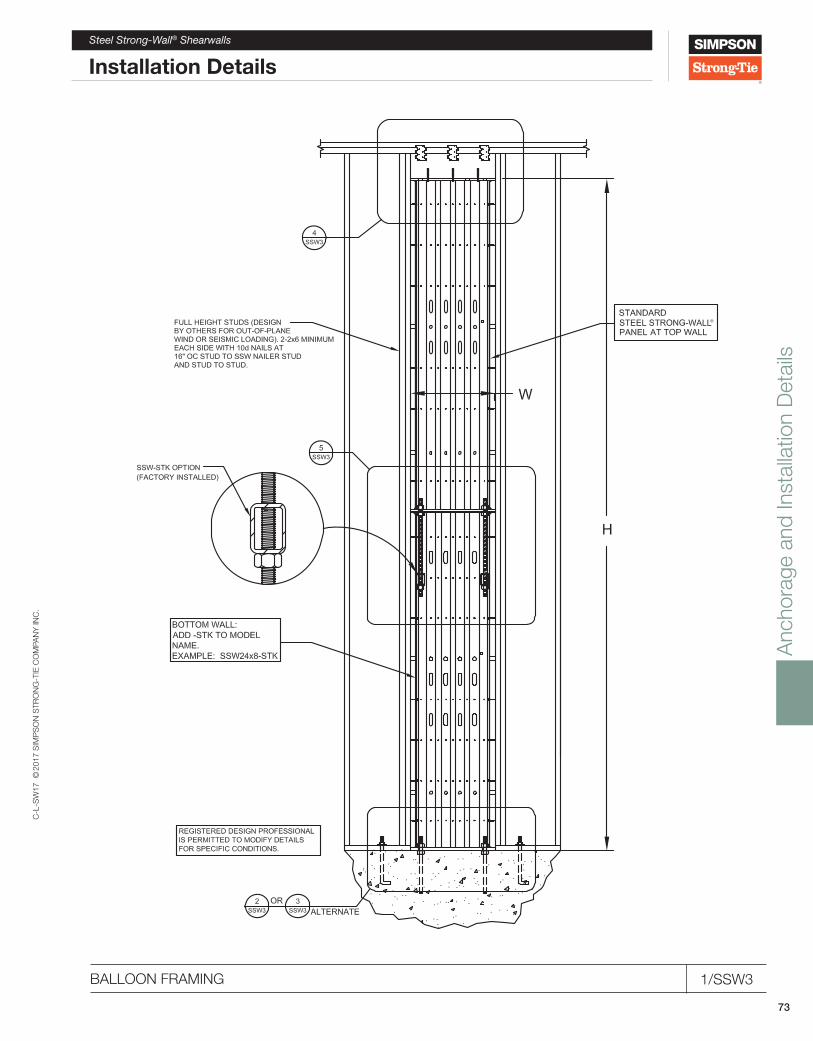
Anc
hora
ge a
nd In
stal
latio
n D
etai
ls
C-L
-SW
17 ©
2017
SIM
PS
ON
STR
ON
G-T
IE C
OM
PAN
Y IN
C.
73
Steel Strong-Wall® Shearwalls
Installation Details
®
BALLOON FRAMING 1/SSW3

Anc
hora
ge a
nd In
stal
latio
n D
etai
ls
C-L
-SW
17 ©
2017
SIM
PS
ON
STR
ON
G-T
IE C
OM
PAN
Y IN
C.
74
®
BALLOON FRAMING BASE PLATE CONNECTION 2/SSW3
®
®
Steel Strong-Wall® Shearwalls
Installation Details
BALLOON FRAMING AT WOOD FLOOR 3/SSW3

Anc
hora
ge a
nd In
stal
latio
n D
etai
ls
C-L
-SW
17 ©
2017
SIM
PS
ON
STR
ON
G-T
IE C
OM
PAN
Y IN
C.
75
Steel Strong-Wall® Shearwalls
Installation Details
BALLOON FRAMING TOP OF WALL CONNECTION 4/SSW3
BALLOON FRAMING WALL TO WALL CONNECTION 5/SSW3
®
®
®
®

Anc
hora
ge a
nd In
stal
latio
n D
etai
ls
C-L
-SW
17 ©
2017
SIM
PS
ON
STR
ON
G-T
IE C
OM
PAN
Y IN
C.
76
SINGLE PORTAL ASSEMBLY 1/SSW4
HOLDOWN (MIN.)S
SIMPSONSTRONG-TIE
THD10
(DESIGN BY OTHERS)HEADER SUPPORT POSTLSTA24 STRAP (MIN.)
AT BEAM TO POST
8' MIN. 16' - 4" MAX.
(DESIGN BY OTHERS)COLUMN BASE
3
4
PORTAL STRAP AND#14 SELF-DRILLING SCREWS(PROVIDED WITH SSWP-KT)
318" MIN WIDTH HEADER BY OTHERS.
SEE . SEE FOR MULTI-PLY
HEADER REQUIREMENTS4
STEEL STRONG-WALL SHEARWALL(EXTERIOR FACE)
SIM.
5
HCURB
®®
5
PORTAL STRAP AND#14 SELF-DRILLING SCREWS.(PROVIDED WITH SSWP-KT)
FULL LENGTH GARAGE HEADER(DESIGN BY OT EH RS)MINIMUM SIZE SHALL BE:4x12 DFL31/8X12 GLBALTERNATE HEADERS ALLOWED.(DESIGN BY OTHERS)FOR MULTI-PLY HEADER REQUIREMENTS
SEE
FIELD NAIL PORTAL STRAPTO HEADER WITH (10) 10dX21
2 MIN. NAILS.FASTEN STRAP TO PANELWITH (4) #14 SELF-DRILLING SCREWS.(SCREWS PROVIDED WITH SSWP-KT)
ALIGN NOTCH ON STRAPWITH BOTTOM OF HEADER.
SDS 14"x31
2" SCREWS(PROVIDED)
NOTE:LOAD PATH DESIGN ANDDETAILS ABOVE HEADER TOBE PROVIDED BY OTHERS.
NOTE:STRAPS MUST BE INSTALLEDON EXTERIOR FACE OF SSWPANEL. POSITION HEADERFLUSH WITH EXTERIORFACE OF SSW PANEL.
STEEL STRONG-WALL SHEARWALL(EXTERIOR FACE)
7/8" MAX. SHIM ALLOWED BETWEENPANEL AND BEAM (NOT SHOWN).
®
Steel Strong-Wall® Shearwalls
Installation Details
PORTAL TOP CONNECTION 4/SSW4

Anc
hora
ge a
nd In
stal
latio
n D
etai
ls
C-L
-SW
17 ©
2017
SIM
PS
ON
STR
ON
G-T
IE C
OM
PAN
Y IN
C.
77
Strong-Wall® Wood Shearwalls
Installation Details
STRONG-WALL® WOOD SHEARWALL – TYPICAL SECTIONS 1/WSW1

Anc
hora
ge a
nd In
stal
latio
n D
etai
ls
C-L
-SW
17 ©
2017
SIM
PS
ON
STR
ON
G-T
IE C
OM
PAN
Y IN
C.
78
STRONG-WALL® WOOD SHEARWALL TENSION ANCHORAGE SCHEDULE 2/WSW1
Strong-Wall® Wood Shearwalls
Installation Details

Anc
hora
ge a
nd In
stal
latio
n D
etai
ls
C-L
-SW
17 ©
2017
SIM
PS
ON
STR
ON
G-T
IE C
OM
PAN
Y IN
C.
79
Strong-Wall® Wood Shearwalls
Installation Details
STRONG-WALL® WOOD SHEARWALL TENSION ANCHORAGE SCHEDULE 2/WSW1

Anc
hora
ge a
nd In
stal
latio
n D
etai
ls
C-L
-SW
17 ©
2017
SIM
PS
ON
STR
ON
G-T
IE C
OM
PAN
Y IN
C.
80
STRONG-WALL® WOOD SHEARWALL SHEAR ANCHORAGE SCHEDULE AND DETAILS 5/WSW1
Installation DetailsStrong-Wall® Wood Shearwalls

Anc
hora
ge a
nd In
stal
latio
n D
etai
ls
C-L
-SW
17 ©
2017
SIM
PS
ON
STR
ON
G-T
IE C
OM
PAN
Y IN
C.
81
Strong-Wall® Wood Shearwalls
Installation Details
WSW-AB ANCHOR GRADE BEAM REINFORCEMENT AND DESIGN MOMENTS 5/WSW1.1
GRADE BEAM SECTION AT ANCHOR REINFORCEMENT
GRADE BEAM SECTION AWAY FROM ANCHOR REINFORCEMENT 4/WSW1.13/WSW1.1
GRADE BEAM ELEVATION AT 24" WALL MODEL
GRADE BEAM ELEVATION AT 12" AND 18" WALL MODELS 2/WSW1.11/WSW1.1

Anc
hora
ge a
nd In
stal
latio
n D
etai
ls
C-L
-SW
17 ©
2017
SIM
PS
ON
STR
ON
G-T
IE C
OM
PAN
Y IN
C.
82
SINGLE-STORY STRONG-WALL® WOOD SHEARWALL ON CONCRETE 2/WSW2
Installation DetailsStrong-Wall® Wood Shearwalls

Anc
hora
ge a
nd In
stal
latio
n D
etai
ls
C-L
-SW
17 ©
2017
SIM
PS
ON
STR
ON
G-T
IE C
OM
PAN
Y IN
C.
83
Installation DetailsStrong-Wall® Wood Shearwalls
ALTERNATE WSW GARAGE FRONT OPTIONS 3/WSW2

Anc
hora
ge a
nd In
stal
latio
n D
etai
ls
C-L
-SW
17 ©
2017
SIM
PS
ON
STR
ON
G-T
IE C
OM
PAN
Y IN
C.
84
WOOD FLOOR SYSTEM BASE CONNECTION 5/WSW2
STANDARD INSTALLATION BASE CONNECTION 4/WSW2
Strong-Wall® Wood Shearwalls
Installation Details

Anc
hora
ge a
nd In
stal
latio
n D
etai
ls
C-L
-SW
17 ©
2017
SIM
PS
ON
STR
ON
G-T
IE C
OM
PAN
Y IN
C.
85
Strong-Wall® Wood Shearwalls
Installation Details
ALTERNATE TOP CONNECTION 7/WSW2
STANDARD TOP CONNECTION 6/WSW2

Anc
hora
ge a
nd In
stal
latio
n D
etai
ls
C-L
-SW
17 ©
2017
SIM
PS
ON
STR
ON
G-T
IE C
OM
PAN
Y IN
C.
86
RAKE WALL 8/WSW2
Strong-Wall® Wood Shearwalls
Installation Details

Anc
hora
ge a
nd In
stal
latio
n D
etai
ls
C-L
-SW
17 ©
2017
SIM
PS
ON
STR
ON
G-T
IE C
OM
PAN
Y IN
C.
87
Strong-Wall® Wood Shearwalls
Installation Details
TOP-OF-WALL HEIGHT ADJUSTMENTS 9/WSW2

Anc
hora
ge a
nd In
stal
latio
n D
etai
ls
C-L
-SW
17 ©
2017
SIM
PS
ON
STR
ON
G-T
IE C
OM
PAN
Y IN
C.
88
TRIM ZONES AND ALLOWABLE HOLES 10/WSW2
Strong-Wall® Wood Shearwalls
Installation Details

Anc
hora
ge a
nd In
stal
latio
n D
etai
ls
C-L
-SW
17 ©
2017
SIM
PS
ON
STR
ON
G-T
IE C
OM
PAN
Y IN
C.
89
Strong-Wall® Wood Shearwalls
Installation Details
TWO-STORY STACKED ELEVATION 2/WSW3

Anc
hora
ge a
nd In
stal
latio
n D
etai
ls
C-L
-SW
17 ©
2017
SIM
PS
ON
STR
ON
G-T
IE C
OM
PAN
Y IN
C.
90
TWO-STORY STACKED INSTALLATION 3/WSW3
Strong-Wall® Wood Shearwalls
Installation Details

Anc
hora
ge a
nd In
stal
latio
n D
etai
ls
C-L
-SW
17 ©
2017
SIM
PS
ON
STR
ON
G-T
IE C
OM
PAN
Y IN
C.
91
Strong-Wall® Word Shearwalls
Installation Details
BALLOON FRAMING PANELS OVER 18 FT. TALL 4/WSW3

Anc
hora
ge a
nd In
stal
latio
n D
etai
ls
C-L
-SW
17 ©
2017
SIM
PS
ON
STR
ON
G-T
IE C
OM
PAN
Y IN
C.
92
PORTAL TOP CONNECTION 3/WSW4
STRONG-WALL® WOOD SHEARWALL SINGLE PORTAL ASSEMBLY 1/WSW4
Strong-Wall® Wood Shearwalls
Installation Details
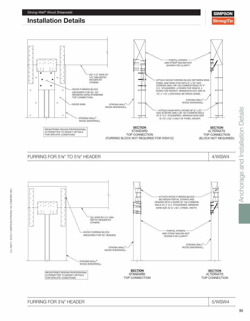
Anc
hora
ge a
nd In
stal
latio
n D
etai
ls
C-L
-SW
17 ©
2017
SIM
PS
ON
STR
ON
G-T
IE C
OM
PAN
Y IN
C.
93
Installation DetailsStrong-Wall® Wood Shearwalls
FURRING FOR 3 1/8" HEADER 5/WSW4
FURRING FOR 5 1/8" TO 5 1⁄2" HEADER 4/WSW4
SECTIONSTANDARD
TOP CONNECTION
SECTIONALTERNATE
TOP CONNECTION
318" WIDE BY 9 14" MIN.
DEPTH HEADER BYOTHERS
WOOD FURRING BLOCK(REQUIRED FOR 31
8" HEADER)
STRONG-WALL®
WOOD SHEARWALL
ATTACH WOOD FURRING BLOCKBETWEEN PORTAL STRAPS AND
HEADER WITH 2 ROWS OF 10d COMMONNAILS AT 3" O.C. STAGGERED. MINIMUMSHIM SIZE IS 3 8" x 91
4" x PANEL WIDTH.
STRONG-WALL®
WOOD SHEARWALLSTRONG-WALL®
WOOD SHEARWALL
PORTAL STRAPSAND STRAP NAILING NOT
SHOWN FOR CLARITY
REGISTERED DESIGN PROFESSIONALIS PERMITTED TO MODIFY DETAILSFOR SPECIFIC CONDITIONS.

C-L
-SW
17 ©
2017
SIM
PS
ON
STR
ON
G-T
IE C
OM
PAN
Y IN
C.
94
Notes

C-L
-SW
17 ©
2017
SIM
PS
ON
STR
ON
G-T
IE C
OM
PAN
Y IN
C.
95
Notes

C-L
-SW
17 ©
2017
SIM
PS
ON
STR
ON
G-T
IE C
OM
PAN
Y IN
C.
96
Notes

C-L
-SW
17 ©
2017
SIM
PS
ON
STR
ON
G-T
IE C
OM
PAN
Y IN
C.
97
Notes

C-L
-SW
17 ©
2017
SIM
PS
ON
STR
ON
G-T
IE C
OM
PAN
Y IN
C.
98
Notes

99
Every day we work hard to earn your business, blending the talents of our people with the quality of our products and services to exceed your expectations. This is our pledge to you.
Home Office5956 W. Las Positas BoulevardPleasanton, CA 94588 Tel: (925) 560-9000Fax: (925) 847-1603
Northwest USA5151 S. Airport WayStockton, CA 95206Tel: (209) 234-7775Fax: (209) 234-3868
Southwest USA12246 Holly StreetRiverside, CA 92509Tel: (714) 871-8373Fax: (951) 369-2889
Northeast USA2600 International StreetColumbus, OH 43228Tel: (614) 876-8060Fax: (614) 876-0636
Southeast USA 2221 Country LaneMcKinney, TX 75069Tel: (972) 542-0326Fax: (972) 542-5379
Eastern Canada5 Kenview BoulevardBrampton, ON L6T 5G5Tel: (905) 458-5538Fax: (905) 458-7274
Western Canada11476 Kingston StreetMaple Ridge, B.C. V2X 0Y5Tel: (604) 465-0296Fax: (604) 465-0297
Distribution CentersChandler, AZ; Eagan, MN; Enfield, CT; High Point, NC; Houston, TX; Jacksonville, FL; Kansas City, KS; Kent, WA; Jessup, MD
International FacilitiesPlease visit our website for address and contact information for our European facilities.
(800) 999-5099strongtie.com

The Simpson Strong-Tie® Shearwall Selector web application helps designers choose shearwall solutions based on usage and building code. The web app complies with the 2015 International Building Code and includes our new Strong-Wall® wood shearwall.
For more information, call (800) 999-5099 or visit strongtie.com/swss.
Select the right shearwall with the Strong-Wall® Shearwall Selector.
Simplify the process.
C-L-SW17 Effective 7/1/2017 Expires 6/30/2018
© 2017 Simpson Strong-Tie Company Inc.