Haptic based wall
6
Haptic based waling stick for visually impaired people M. P. Menikdiwela 1 , K.M.I.S.Dharmasena 2 , A.M. Harsha S. Abeykoon 3 Department of Electrical Engineering, University of Moratuwa Katubedda, Moratuwa, Sri Lanka I [email protected] 2 [email protected] 3 [email protected] Abstract- This paper proposes a new product concept of an electronic travelling aid with haptic perception for the visually impaired people. The device is much similar to the conventional white cane in appearance and it is fabricated using ultrasonic sensors, a vibrator motor scheme, a controller and a power unit inside the walking stick. The sensor system comprises of three ultrasonic sensors to acquire obstacle distance measurements and the user can interpret the distance information as a tactile sensation. The sonar sensors are fired with a sequential firing mechanism to avoid crosstalk. Distance is felt by the user in terms of the vibration intensity change. This device was tested with blind school students and results are presented. Keywords- haptic sensation, vibration feedback, walking stick, navigational aids I. INTRODUCTION Each individual should have the ability to move independently and safely around the environment. The visually impaired people lack the ability of independently walking without a special aid. Thus, the electronic travelling aids (ETA) [1] have been developed to provide the necessary support for visually impaired individuals. Most commonly used methods of supporting the visually impaired people are employing animals such as guard dogs, sighted souls and devices. Because of the technological improvements, these conventional methods are being replaced with much more sophisticated electronic based equipment. Different detection principles are used to detect obstacles. Sometimes a laser or ultrasonic beams are used in order to detect the obstacles. For instance the "Navbelt" which is a guidance system developed by Borenstein et al. in University of Michigan, uses ultrasonic range sensors [2]. With the help of eight sensors the system manages to create a map of the angles and the distance of any object at a certain angle [3]. Stereo vision cameras and complex image processing mechanisms have been used to identify obstacles [4][5][6]. The "voice" system implemented by the Meijer et al. [7], which is based on one-to-one image- to-sound mapping, uses digital cameras and headphones to capture images and interpret them as rapidly changing sound patterns. The "NA V system intended to assist blind people for obstacle identification during navigation [8]. The captured video frames are analyzed using 'fuzzy learning vector quantization' neural network to classify the pixels either as background or objects. The scientist of Wright State University has developed a 2D vibration array used as a major component of an assistive wearable navigation device for visual impaired people [9]. Auditory way of giving a feedback regarding the environment is widely used and is being used in "navi" and "voice" [ I 0]. Use of auditory feedback has both advantages as well as disadvantages. It is clear that interference of hearing process makes the visually impaired person auditory impaired as well. Auditory based navigation system sometimes creates a nuisance to the user. But on the other hand with the use of auditory data, more precise and a higher range can be achieved as different sequences and loudness options can be chosen. It is well understood that human's hearing system is quite capable of learning to process and interpret extremely complicated and rapidly changing sound patterns. In contrast, haptic based systems provide more convenient solutions. There are numerous ways of providing haptic feedback. The electron-neural vision system (ENVS) by Meer et al. of University of Wollongong [11] exercise this method where it uses transcutaneous electrical nerve stimulation (TENS) unit and the TENS gloves. The information is transformed via TENS to electrical pulses that stimulate the nerves in the skin via electrodes located in the TENS data gloves [12]. Here the amount of stimulation is directly proportional to the distance to the objects. Other methods such as Tactile handle which typically employs a tactile array, where each actuator matches one finger phalanx. All the above mentioned methods are having common demerits. NA VI belts, gloves, stereovision cameras [13][14] etc handling is harder than the traditional white cane for which visually impaired people are used to. Because these instruments are giving extra weight to the person and consume high power. Users usually had to carry big batteries as well. Proposed product is developed using the traditional white cane and it's just below 2kg. If the device fails due to battery exhausting, still it could be used as the traditional white cane. Therefore this product was widely accepted by the blind community because of its ease of use.
-
Upload
khangminh22 -
Category
Documents
-
view
3 -
download
0
Transcript of Haptic based wall
Haptic based wall<ing stick for visually impaired
people M. P. Menikdiwela1, K.M.I.S.Dharmasena2, A.M. Harsha S. Abeykoon3
Department of Electrical Engineering, University of Moratuwa Katubedda, Moratuwa, Sri Lanka
[email protected] 2 [email protected]
Abstract- This paper proposes a new product concept of an electronic travelling aid with haptic perception for the visually impaired people. The device is much similar to the conventional white cane in appearance and it is fabricated using ultrasonic sensors, a vibrator motor scheme, a controller and a power unit inside the walking stick. The sensor system comprises of three ultrasonic sensors to acquire obstacle distance measurements and the user can interpret the distance information as a tactile sensation. The sonar sensors are fired with a sequential firing mechanism to avoid crosstalk. Distance is felt by the user in terms of the vibration intensity change. This device was tested with blind school students and results are presented.
Keywords- haptic sensation, vibration feedback, walking stick, navigational aids
I. INTRODUCTION
Each individual should have the ability to move independently and safely around the environment. The visually impaired people lack the ability of independently walking without a special aid. Thus, the electronic travelling aids (ETA) [1] have been developed to provide the necessary support for visually impaired individuals. Most commonly used methods of supporting the visually impaired people are employing animals such as guard dogs, sighted souls and devices. Because of the technological improvements, these conventional methods are being replaced with much more sophisticated electronic based equipment.
Different detection principles are used to detect obstacles. Sometimes a laser or ultrasonic beams are used in order to detect the obstacles. For instance the "Navbelt" which is a guidance system developed by Borenstein et al. in University of Michigan, uses ultrasonic range sensors [2]. With the help of eight sensors the system manages to create a map of the angles and the distance of any object at a certain angle [3]. Stereo vision cameras and complex image processing mechanisms have been used to identify obstacles [4][5][6]. The "voice" system implemented by the Meijer et al. [7], which is based on one-to-one imageto-sound mapping, uses digital cameras and headphones to capture images and interpret them as rapidly changing sound patterns. The "NA VJ" system intended to assist blind people for obstacle identification during navigation [8].
The captured video frames are analyzed using 'fuzzy learning vector quantization' neural network to classify the pixels either as background or objects. The scientist of Wright State University has developed a 2D vibration array used as a major component of an assistive wearable navigation device for visual impaired people [9].
Auditory way of giving a feedback regarding the environment is widely used and is being used in "navi" and "voice" [ I 0]. Use of auditory feedback has both advantages as well as disadvantages. It is clear that interference of hearing process makes the visually impaired person auditory impaired as well. Auditory based navigation system sometimes creates a nuisance to the user. But on the other hand with the use of auditory data, more precise and a higher range can be achieved as different sequences and loudness options can be chosen. It is well understood that human's hearing system is quite capable of learning to process and interpret extremely complicated and rapidly changing sound patterns.
In contrast, haptic based systems provide more convenient solutions. There are numerous ways of providing haptic feedback. The electron-neural vision system (ENVS) by Meer et al. of University of Wollongong [11] exercise this method where it uses transcutaneous electrical nerve stimulation (TENS) unit and the TENS gloves. The information is transformed via TENS to electrical pulses that stimulate the nerves in the skin via electrodes located in the TENS data gloves [12]. Here the amount of stimulation is directly proportional to the distance to the objects. Other methods such as Tactile handle which typically employs a tactile array, where each actuator matches one finger phalanx. All the above mentioned methods are having common demerits. NA VI
belts, TENS gloves, stereovision cameras [13][14] etc handling is harder than the traditional white cane for which visually impaired people are used to. Because these instruments are giving extra weight to the person and consume high power. Users usually had to carry big batteries as well. Proposed product is developed using the traditional white cane and it's just below 2kg. If the device fails due to battery exhausting, still it could be used as the traditional white cane. Therefore this product was widely accepted by the blind community because of its ease of use.
II. SYSTEM CONFIGURATION
Handle with Haptic
perception
Circuit board with the
flC enclosed here
Sensor scheme for
obstacle detection
The charging port
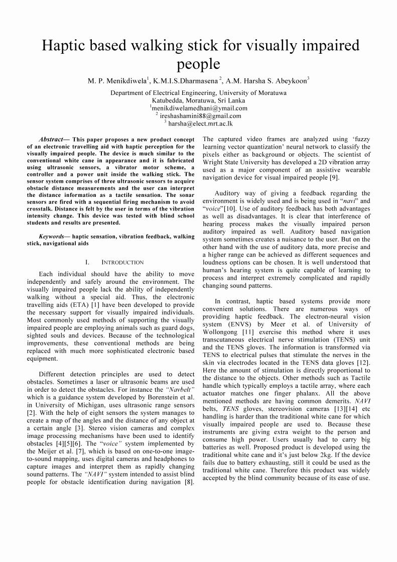
Fig. I Overview of the walking stick
Figure 1 shows the overview of the proposed walking
stick which is similar in appearance to the traditional white
cane. The system consists of a sensor panel for obstacle
detection and a set of vibrator motors were positioned inside the handle to alert about the obstacles. The sensor
signal was processed by the controller to feel the vibration
intensity variation which is proportional to the distance to
the obstacle.
A. Recreating Human Visual Field
Normally, the human visual field covers an area of 180
degrees horizontally and vertically. In the proposed design,
the visual field was selected horizontally up to 150 degree and vertically up to 60 degrees and is adequate when
walking.
B. Sensor System
There were two options when choosing the sensors for
data acquiring, either Sonar sensors or I R sensors. Sonar
sensors had been chosen because it is the most effective sensor type to detect obstacles in an area. Then a test was
carried out to measure the compatibility of the sensor with
the design requirements. The sensor readings had been
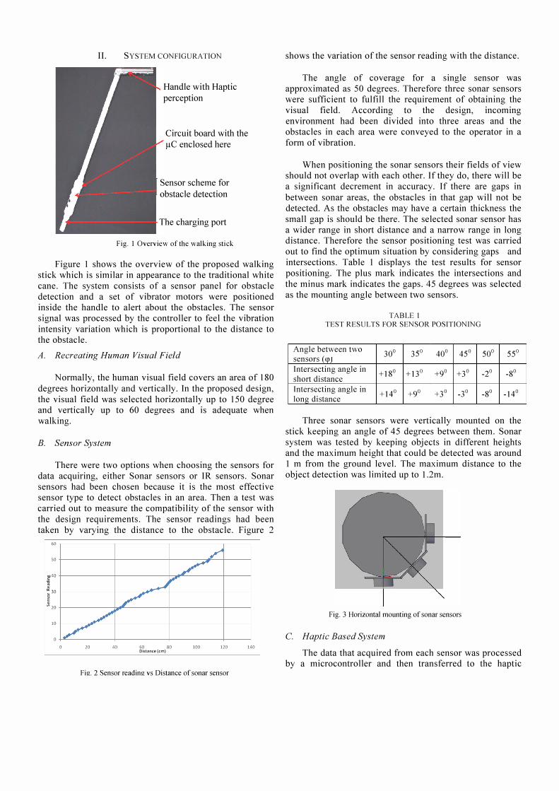
taken by varying the distance to the obstacle. Figure 2
60
50 ./ ./
V �40
,.... ] � � 30
� ./ � 20
../ 10
/ 0
0 20 40 60 80 100 120 140 Distance (em)
Fig. 2 Sensor reading vs Distance of sonar sensor
shows the variation of the sensor reading with the distance.
The angle of coverage for a single sensor was
approximated as 50 degrees. Therefore three sonar sensors were sufficient to fulfill the requirement of obtaining the
visual field. According to the design, incoming
environment had been divided into three areas and the
obstacles in each area were conveyed to the operator in a
form of vibration.
When positioning the sonar sensors their fields of view should not overlap with each other. If they do, there will be
a significant decrement in accuracy. If there are gaps in
between sonar areas, the obstacles in that gap will not be
detected. As the obstacles may have a certain thickness the
small gap is should be there. The selected sonar sensor has
a wider range in short distance and a narrow range in long distance. Therefore the sensor positioning test was carried
out to find the optimum situation by considering gaps and
intersections. Table 1 displays the test results for sensor
positioning. The plus mark indicates the intersections and
the minus mark indicates the gaps. 45 degrees was selected
as the mounting angle between two sensors.
TABLE I
TEST RESULTS FOR SENSOR POSITIONING
Angle between two 30° 35° 40° 45° 50° 55° sensors (q» Intersecting angle in + ISo +13° +9° +3° _2°
-So short distance Intersecting angle in +14° +9° +3° _3°
-So _14° long distance
Three sonar sensors were vertically mounted on the
stick keeping an angle of 45 degrees between them. Sonar
system was tested by keeping objects in different heights
and the maximum height that could be detected was around
I m from the ground level. The maximum distance to the
object detection was limited up to l.2m.
Fig. 3 Horizontal mounting of sonar sensors
C. Haptic Based System
The data that acquired from each sensor was processed by a microcontroller and then transferred to the haptic

based system. Received signals were transferred to the
person in a form of vibration.
After compromising between the advantages and disadvantages, haptic perception was selected as the
medium of data transferring. Solenoids valves and vibrator
motors can be used to generate the haptic sense. Among
them vibrator motor was the most feasible option.
According to the design every vibrator motor was
assigned to a separate sonar sensor. The sensor signals were transformed to a PWM based signal. The PWM duty
is inversely proportional to the distance. The distance to
the obstacle could be identified by the changing intensity
of the vibration.
Slots to position
vibrators
Fig. 4 Side view showing the joint and the slots
As shown in figure 4, three slots were allocated for
vibration and one as a power switch. The vibrators were
positioned inside the cavity with a rubber enclosure layer to avoid the spread out of the vibration to the handle. If not
such vibrations could easily mislead the operator.
III. CONTROLLER DESIGN
Two major controlling parts included in this design are
eliminating the cross talk and signal processing for the vibrators.
A. Eliminating the Crosstalk
Three sonar sensors were operated with the sequential
firing method. This firing method was selected to avoid the
occurrence of crosstalk. Operating cycle of a single sensor
would take less than 40 ms so that, to start the next triggering cycle it would take a maximum of 120ms.
Therefore it does not affect to the speed of the process.
This process was continued by triggering each sensor one
after the other.
Figure 5 shows the functional block diagram of the data acquisitioning system.
Call the next sensor
Ending the Trig Pulse
Sending Signal to the relevant vibrator
the rising
edge of echo
Process the
distance
measurement
No
echo Signal40ms
Calculate the distance using counter values
Fig. 5 The functional block diagram - algorithm for data acquisition
B. Signal Processing for the Vibrators
Visually impaired person should be able to discriminate
the distance to the obstacle. Walking stick was designed,
such that the proximity to the obstacle was represented as
the vibration intensity. Vibration intensity was controlled
using the PWM duty fed to the vibrator motors.
A.
IV. HARDWARE IMPLEMENTATION
Fabrication of the Circuit Board
This circuit was included with two voltage regulator ICs
which supply power to the microcontroller and the vibrator
arrangement separately. 7V was supplied to the voltage
regulator to get the required output of 5V. The IC can
withstand high power dissipation related effects and handle
output current up to 1.5A.
Vibrator motors were fed power through an integrated circuit that consists of high current Darlington arrays. It
provides protection to the microcontroller from the
draining high currents of vibratos motors.
B. Microcontroller
Mbed micro controller was used as the main controller
because it has a high processing speed, easy programming
capability with C/C+ languages and the user friendly
interface for testing. The design required several PWM
ports and that was fulfilled by the mbed.
C. Power Supply Unit
The maximum power usage of the system was 1.27W.
The system should be able to operate at least six hours
continuously without recharging. Therefore, it required a
battery with 1500 mAh.
The battery was charged with a 12V DC power supply.
A power supply unit which has 300 rnA capacity
transformer was designed to recharge the battery pack. The
charging port of the stick was designed with an easy plugging mechanism.
V. RESULTS
Several tests conducted to check the usability of haptic
based walking stick. A group of blind students from Ratmalana blind school, Sri Lanka were selected. Their
response of using the walking stick was recorded and
presented here in the result section. The selected group was
in the age range of 13-16 years who are fully blind.
The identification of the obstacle through vibration
mechanism was a new experience to them. They were used
to walk with the traditional white cane for years. Several
experiments were conducted to test them with haptic based
walking stick.
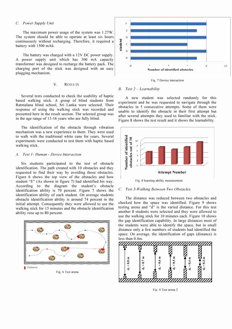
A. Test 1- Human - Device Interaction
Six students participated to the test of obstacle
identification. The path created with 10 obstacles and they
requested to find their way by avoiding those obstacles.
Figure 6 shows the top view of the obstacles and how
student "E" (As shown in figure 7) had identified his way.
According to the diagram the student's obstacle
identification ability is 70 percent. Figure 7 shows the
identification ability of each student. On average students
obstacle identification ability is around 74 percent in the
initial attempt. Consequently they were allowed to use the
walking stick for 15 minutes and the obstacle identification
ability rose up to 80 percent.
----��\
-4----- ----� // .................... .
t Collisions
Fig. 6 Test arena
F
E
D
c
B
o Nllmhpr of i<lpntifip<l ohd""lp<
Fig. 7 Device interaction
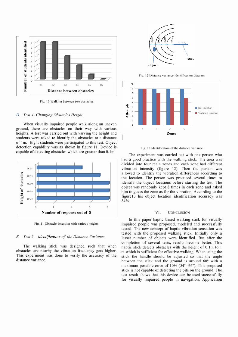
B. Test 2 - Learnability
8
A new student was selected randomly for this
experiment and he was requested to navigate through the
obstacles in 5 consecutive attempts. Some of them were
unable to identify the obstacle in their first attempt but after several attempts they used to familiar with the stick.
Figure 8 shows the test result and it shows the learnability.
"0 �e :; : 10 ::;
C 8 � ... "0 == ;.: 0 o � �� ..c!l
6
4
e 'I; =..0.
Z C o �----�----�----�----�----�
Attempt Number
Fig. 8 learning ability measurement
C. Test 3-Walking Between Two Obstacles.
The distance was reduced between two obstacles and
checked how the space was identified. Figure 9 shows
testing arena and "d" is the varied distance. For this test another 8 students were selected and they were allowed to
use the walking stick for 1 0 minutes each. Figure 1 0 shows
the gap identification capability. In large distances most of
the students were able to identify the space, but in small distance only a few numbers of students had identified the
space. On average, the identification of gaps (distance) is
less than O.4m.
�:.I �� �a 8 E E 8 E E
IX) t- � on ..,. t� = = = = = II II II II II ..0 -0 -0 -0 -0 -d
r� �� ��
Fig. 9 Test arena 2
10
"0 8 Q,j
5 7 ..... I:
6 Q,j
:5! 5
rIJ ..... I: 4 Q,j
"0 3 = .....
2 rIJ ... 0
I-Q,j
..Q 0
:: dl d2 d3 dL do
=
Z Distance between obstacles
Fig. 10 Walking between two obstacles.
D. Test 4- Changing Obstacles Height.
dG
When visually impaired people walk along an uneven ground, there are obstacles on their way with various
heights. A test was carried out with varying the height and
students were asked to identify the obstacles at a distance
of 1 m. Eight students were participated to this test. Object detection capability was as shown in figure 11. Device is
capable of detecting obstacles which are greater than O.lm.
O.lm
rIJ
(1 I 1
J I I 1 Q,j
O.2n � � ..... I I I I rIJ
O.3m ..Q 0 ... I I I I 0 DAm ..... .c I I I I �
O.Sm .Q:j :c
./ ./ / /
o 4 G
Number of response out of 8
Fig. II Obstacle detection with various heights
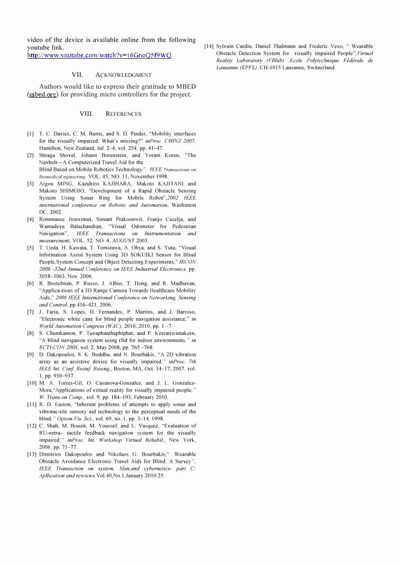
E. Test 5 - Identification of the Distance Variance
8
The walking stick was designed such that when obstacles are nearby the vibration frequency gets higher.
This experiment was done to verify the accuracy of the
distance variance.
Fig. 12 Distance variance identification diagram
• Rea Locction
• Predicted _ocation
Zones
Fig. 13 Identification of the distance variance
The experiment was carried out with one person who
had a good practice with the walking stick. The area was
divided into four main zones and each zone had different
vibration intensity (figure 12). Then the person was allowed to identify the vibration differences according to
the location. The person was practiced several times to identify the object locations before starting the test. The object was randomly kept 8 times in each zone and asked him to guess the zone as for the vibration. According to the
figure 13 his obj ect location identification accuracy was
84%.
VI. CONCLUSION
In this paper haptic based walking stick for visually
impaired people was proposed, modeled and successfully tested. The new concept of haptic vibration sensation was tested with the proposed walking stick. Initially only a
lesser number of objects were identified. But after the
completion of several tests, results become better. This
haptic stick detects obstacles with the height of O.lm to 1 m which is sufficient for effective walking. When using the
stick the handle should be adjusted so that the angle between the stick and the ground is around 60° with a
maximum possible error of 10% (54°- 66°). This proposed stick is not capable of detecting the pits on the ground. The test result shows that this device can be used successfully
for visually impaired people in navigation. Application
video of the device is available online from the following youtube link. http://www.youtube.com/watch?v=16GnoQ5f9WQ
VII. ACKNOWLEDGMENT
Authors would like to express their gratitude to MBED
(mbed.org) for providing micro controllers for the project.
VIII. REFERENCES
[1] T. C. Davies, C. M. Burns, and S. D. Pinder, "Mobility interfaces
for the visually impaired: What's missing?" inProc. CHINZ 2007.
Hamilton, New Zealand, .luI. 2-4, vol. 254, pp. 41-47.
[2] Shraga Shoval, Johann Borenstein, and Yoram Koren, "The
Navbelt-A Computerized Travel Aid for the
Blind Based on Mobile Robotics Technology", IEEE Transactions on
Riomedicai ngineering, VOL. 45, NO. II, November 1998.
[3] Aigou MING, Kazuhiro KAJIHARA, Makoto KAJITANI and
Makoto SHIMOJO, "Development of a Rapid Obstacle Sensing
System Using Sonar Ring for Mobile Robot ",2002 IEEE
international conference on Robotic and Automation, Washinton DC, 2002.
[4] Rommanee Jirawimut, Simant Prakoonwit, Franjo Cecelja, and
Wamadeva Balachandran, "Visual Odometer for Pedestrian
Navigation ", IEEE Transactions on Instrumentation and
measurement, VOL. 52, NO. 4, AUGUST 2003. [5] T. Ueda, H. Kawata, T. Tomizawa, A. Ohya, and S. Yuta, "Visual
Information Assist System Using 3D SOKUIKI Sensor for Blind
People,System Concept and Object Detecting Experiments," IECON
2006 -32nd Annual Conference on IEEE Industrial Electronics, pp.
3058-3063, Nov. 2006.
[6] R. Bostelman, P. Russo, 1. Albus, 1. Hong, and R. Madhavan,
"Applica-tions of a 3D Range Camera Towards Healthcare Mobility Aids," 2006 IEEE International Conference on Networking, Sensing
and Control, pp.416-421, 2006.
[7] J. Faria, S. Lopes, H. Fernandes, P. Martins, and J. Barroso,
"Electronic white cane for blind people navigation assistance," in
World Automation Congress (WAC), 2010,2010, pp. 1 -7.
[8] S. Chumkamon, P. Tuvaphanthaphiphat, and P. Keeratiwintakorn,
"A blind navigation system using rfid for indoor environments, " in
ECTI-CON 2008, vol. 2, May 2008, pp. 765 -768.
[9] D. Dakopoulos, S. K. Boddhu, and N. Bourbakis, "A 2D vibration
array as an assistive device for visually impaired," inProc. 7th
IEEE Int. Conj Bioinj Bioeng., Boston, MA, Oct. 14-17,2007, vol.
I, pp. 930-937.
[10] M. A. Torres-Gil, O. Casanova-Gonzalez, and 1. L. Gonzalez
Mora, "Applications of virtual reality for visually impaired people, "
W Trans. on Comp., vol. 9, pp. 184-193, February 2010.
[II] R. D. Easton, "Inherent problems of attempts to apply sonar and
vibrotac-tile sensory aid technology to the perceptual needs of the blind, " Optom. Vis. Sci., vol. 69, no. 1, pp. 3-14, 1998.
[12] C. Shah, M. Bouzit, M. Youssef, and L. Vasquez, "Evaluation of
RU-netra- tactile feedback navigation system for the visually impaired," inProc. Int. Workshop Virtual Rehabil., New York,
2006, pp. 71-77.
[13] Dimitrios Dakopoulos and Nikolaos G. Bourbakis," Wearable
Obstacle Avoidance Electronic Travel Aids for Blind: A Survey",
IEEE Transaction on system, Man,and cybernetics- part C:
Apllication and rewiews, VoI.40,No.1 ,January 2010 25.
[14] Sylvain Cardin, Daniel Thalmann and Frederic Vexo, " Wearable
Obstacle Detection System for visually impaired People ",virtual
Reality Laboratory (VRlab) ,Ecole Poly technique Federale de
Lausanne (EPFL) ,CH-1015 Lausanne, Switzerland.