Standard Compliant Snapshotting for SystemC Virtual Platforms

Constraint-Based Haptic Rendering ofMultirate Compliant Mechanisms
Igor Peterlık, Mourad Nouicer, Christian Duriez,
Stephane Cotin, and Abderrahmane Kheddar, Member, IEEE
Abstract—The paper is dedicated to haptic rendering of complex physics-based environment in the context of surgical simulation. A
new unified formalism for modeling the mechanical interactions between medical devices and anatomical structures and for computing
accurately the haptic force feedback is presented. The approach deals with the mechanical interactions using appropriate force and/or
motion transmission models named compliant mechanisms. These mechanisms are formulated as a constraint-based problem that is
solved in two separate threads running at different frequencies. The first thread processes the whole simulation including the soft-
tissue deformations, whereas the second one only deals with computer haptics. This method builds a bridge between the so-called
virtual mechanisms (that were proposed for haptic rendering of rigid bodies) and intermediate representations (used for rendering of
complex simulations). With this approach, it is possible to describe the specific behavior of various medical devices while relying on a
unified method for solving the mechanical interactions between deformable objects and haptic rendering. The technique is
demonstrated in interactive simulation of flexible needle insertion through soft anatomical structures with force feedback.
Index Terms—Haptic rendering, deformable, heterogeneous constraints, contact modeling, physically-based simulation, needle
simulation, laparoscopic simulation, compliance, multithread, multirate, virtual mechanisms, intermediate representation.
Ç
1 INTRODUCTION
COMPUTER-BASED interactive simulations are an importantalternative to conventional training in medicine. Many
improvements have been made since the pioneering worksstarted 15 years ago. Nowadays, real-time biomechanicalmodels are gaining reliability in describing the behavior ofsoft tissues, and models parameters can be set with actualpatient data allowing for complex procedure rehearsal. Thisis even strengthened by the development of new minimallyinvasive techniques that typically create a distance betweenthe patient and physician (visualization of the operatingfield through various imaging techniques, complex instru-ments, etc.). To cope with these new intervention methods,advanced medical simulation systems are developed inorder to reduce patient risk during the (often long) learningcurve of the physician. These systems, which often provideboth visual and haptic feedbacks, offer a successfulalternative to animal training [1]. Some simulation systemsalso include a database of pathological cases, which allowfor training safely on cases that are rarely encounteredduring traditional training [2].
To reach the requirement for truthful simulations, there
is an important amount of work dedicated to the develop-
ment of better visual feedback and reliable soft tissue
deformation models [3], [4], [5]. However, significant
improvements remain possible in haptics. Such improve-
ments can certainly be made in part through the develop-
ment of better interfaces, designed to the specific
requirements of intervention techniques, but also through
advanced modeling of the complex interactions that take
place in medical procedures. While an important body of
work was done to model the contact between rigid
instruments and soft structures, there are other types of
interactions that have not been completely addressed. These
interactions are potentially very complex and of different
nature, depending on the instrument and on the nature of
the intervention. Examples of such interactions range from
catheter navigation in interventional radiology, where
complex deformations occur but most of the feedback is
visual, to bone drilling in arthroscopy, where no deforma-
tion takes place and force feedback is important. Yet, in all
cases, the force cue felt by the physician mainly comes from
these interactions. Subsequently, their accurate physical
modeling is of prime importance in order to provide the
user with high fidelity haptic feedback.Our work focuses on complex mechanical interaction
modeling and unifies high fidelity simulation physics and
fast haptics rendering. We propose a computer haptics
scheme that is tailored to the specificity of each medical
instrument and its functionality, i.e., usage in a given
context. We illustrate our method in scenarios using flexible
needles and laparoscopic graspers. However, our approach
is generic and can be applied to any other type of medical
instruments and interventions.
IEEE TRANSACTIONS ON HAPTICS, VOL. 4, NO. 3, JULY-SEPTEMBER 2011 175
. I. Peterlık, C. Duriez and S. Cotin are with INRIA Nord Europe, Lille,France. E-mail: {igor.peterlik, christian.duriez, stephane.cotin}@inria.fr.
. M. Nouicer is with the INI Algiers, Algeria.E-mail: [email protected].
. A. Kheddar is with the Interactive Digital Human Group, CNRS-UM2LIRMM, Montpellier, France, and the CNRS-AIST Joint RoboticsLaboratory (JRL), UMI3218/CRT, Tsukuba, Japan.E-mail: [email protected].
Manuscript received 3 Oct. 2010; revised 10 June 2011; accepted 18 July 2011;published online 21 July 2011.Recommended for acceptance by A. Okamura, C. Basdogan, S. Baillie, andW.S. Harwin.For information on obtaining reprints of this article, please send e-mail to:[email protected], and reference IEEECS Log Number THSI-2010-10-0085.Digital Object Identifier no. 10.1109/ToH.2011.41.
1939-1412/11/$26.00 � 2011 IEEE Published by the IEEE CS, RAS, & CES

2 RELATED WORK AND CONTRIBUTION
In this section, we first provide an overview of thecomputer haptics methods related to this paper. Then, wedescribe the concepts on which our approach is built andour main contributions.
2.1 Related Work
Simulation dynamics and haptic rendering share the samefundamentals: In both cases, mechanical forces must becomputed. The manipulated object interacts with othersand generates reaction forces that feed the physics-basedengine, and more importantly, the controller of the hapticdisplay. In the last case, the computation of the reactionforces is constrained by 1) the need to meet high frequencyrefresh rates, 2) the stability of the device control law, and3) the fidelity of the haptic rendering as perceived by theuser. Several approaches have been proposed to deal withsome or all of these constraints.
In [6], the concept of virtual coupling is proposed.Originally designed to improve the haptic rendering ofvirtual walls, it can be regarded as an artificial mechanicalcoupling which connects the haptic device to the virtualobject. Parameters can be tuned to guarantee the stability ofthe haptic interaction. Since the position of the manipulatedvirtual object is updated from the haptic display handleposition, penetration between virtual objects occurs. A god-object approach is introduced in [7] to increase theperception of stiffness through visually enforcing thenonpenetration. The method is extended by the so-calledvirtual proxy in [8]. These methods can be gathered as virtualcoupling network as noted in [9] and [10] to further improvethe stability and performance of the rendering. Extensionsof the god-object to constraining position and orientation ismade in [11]. The latter is based on a minimization of thekinetic distance between the actual position of the hapticdevice handle and the virtual proxy. God-object techniquecan be regarded as a particular case of our method whensimulating contact interactions between rigid bodies.
The virtual mechanisms concept was proposed for an easydesign of haptic joints in the context of rigid bodiesmanipulation and prototyping [12], [13]. It was initiallydesigned for computing haptics in computer-assisted forcereflecting bilateral teleoperation to improve both robotmaneuverability and stability [14], [15]. Using this techni-que, it is possible to impose various motion constraints tothe teleoperator including nonlinear ones, such as couplingbetween translations and rotations, for instance. The use ofhaptic virtual mechanisms for modeling of articulatedbodies is demonstrated in [13], [16] where the simulationof serial and closed chains is studied. Recently, to achievemore complex set of constraints, the concept of virtualmechanisms has been extended to unilateral contacts by[17]. The particularity of this method, which makes it closeto our approach, is that the constraint solver is embedded inthe control loop of the haptic device. However, it wasimplemented for rigid bodies, therefore the entire solvingprocess is performed at high rates which is generally notpossible with biomechanical models of soft-tissues.
The methods proposed to model the haptic interactionswith deformable bodies are often tailored to given specific
cases and can hardly be generalized to a large range ofconstraints. In the pioneering works [18], [19], a displace-ment-driven interaction is used instead of contact modeling.The positions are applied as bilateral constraints (equalityconditions) and solved by a method of Lagrange multi-pliers. Similarly, the small area paradigm relies on linearmodeling [20], for which the equality boundary conditionsaffects only a small number of surface nodes. Through asimple update of inverse stiffness matrix, the responseforces can be computed at each step of the haptic loop. In[21] and [22], methods based on precomputations areproposed; stable haptic rendering is achieved, since theresponse forces are efficiently calculated from precomputeddata, e.g., by interpolation, performed directly in the hapticloop. Although viscoelastic and nonlinear models areemployed, only point-based interaction is considered dueto limitations given by the precomputations.
In [23], a unified approach to the interaction withelastostatic contact simulation is presented. In this case,the contact resolution is based on capacitance matrix, whichrelates the imposed displacements and response forces.1
The method is used for single-point as well as graspinginteraction, where haptic rates are achieved using precom-puted Green functions. In [24], the contact problem issolved using a penalty-based method allowing for multiplecontacts and self-collisions. Both tool and obstacle aredeformable and simulated by finite elements methodsoptimized thanks to model reduction [24]. The penalty-based methods cannot guarantee the noninterpenetration,they are very sensitive to the choice of the penaltyparameters and do not integrate properly static/dynamicfriction. Therefore, constraint-based methods for contacthandling have been introduced in the field of hapticrendering of contacts despite higher computational costs.
In [25], contact response is formulated as LinearComplementarity Problem (LCP) using unilateral constraintsand the mechanical compliance of FEM models. Interpene-trations are excluded after collision response and themethod can also account for dry/dynamic friction.Although both the tool and obstacle are deformable, onlysmall deformations are considered. In this case, thecompliance matrix can be precomputed.
To overcome the limited refresh rate when dealing withdeformable bodies, one strategy is to implement anintermediate representation of the constraints provided bythe virtual environment, see, e.g., [26], [27], [28]. Thisrepresentation allows for separating the haptic renderingfrom the physics engine, but at the cost of using a simplifiedmodel of the simulation [29]. In [30], a method for renderingrigid tools in frictionless contact with compliant environ-ments is presented. The formulation of the contact issimplified using bilateral constraints at a low-rate loop. Acontact Jacobian is inverted and shared (as an intermediaterepresentation) with the haptic loop for a reevaluation athigh rate force feedback.
Yet, bilateral constraints do not model accurately thecontact. This problem is addressed in [28] where a mixed-LCP formulation combines both linear equalities and
176 IEEE TRANSACTIONS ON HAPTICS, VOL. 4, NO. 3, JULY-SEPTEMBER 2011
1. This matrix is similar to the compliance matrix that we describe in thispaper.

inequalities. A part of the deformable tool (a handle) needsto be rigidified to be connected to the haptic device byviscoelastic link [31]. This mixed-LCP formulation is madefrom a simplified inverse matrix (which is similar to thecompliance matrix) as only diagonal blocks are considered.Thus, indirect contacts cannot be rendered and thecomputation of the direct contact force is not alwaysaccurate, especially for light and stiff objects.
In [32], a technique inspired from corotational FEMmodels is employed for a more accurate yet fast evaluationof the compliance when dealing with nonlinear deforma-tions. The compliance is precomputed and “warped” usinga local evaluation of the rotations, at each node, inside thedeformation field. A stable coupling scheme, similar to thegod-object method, is employed for haptic rendering. Thiscoupling scheme is based on a multirate implementation ofthe contact model solver: The LCP is shared by thesimulation and is iteratively resolved within the hapticloop. Since the contact equations are built at low rates andresolved at high rates, the method in [32] falls in thecategory of intermediate representation, even if there is nosimplification of the contact model in the haptic loop. Theapproach presented in this paper extends this technique forall types of interactions (not only contact) using a general-ized formulation.
2.2 Motivation and Contribution
Many complex interactions occur in medical procedures,such as suturing or grasping, for instance. A particularlyinteresting and complex example of interaction is theinsertion of a (flexible) needle through several layers ofsoft tissues. This well-known problem in simulation andplanning [33], [34] has many applications in medicine:needle biopsy, brachytherapy, cryotherapy, radiofrequencyablation, etc. In all of these applications, the first step is tomodel the interaction of the needle as it punctures ortraverses various tissue layers. The problem is even morecomplex to tackle when interactive high fidelity hapticfeedback is needed.
No existing method proved to cover haptic rendering forall possible task scenarios in interactive surgical simulations.Therefore, the method presented in this paper attempts to fillthis gap by proposing a generic framework for solvingcomplex interactions between various medical devices andanatomical structures, and subsequently computing theassociated haptic rendering. It accounts for large deforma-tions of the tool as well as the organs while at the same time,it handles arbitrary types of constraints, such as unilateralcontacts, nonlinear friction as well as bilateral ones.
From the computer haptic viewpoint, the approach maybe classified as relying on an intermediate representation.The dynamics of the virtual objects is computed at low-ratein the simulation and the interaction forces are modeledand solved using constraints. But these forces are recom-puted at high-rate in the haptic loop based on anintermediate representation shared between the two loops.This intermediate representation includes: 1) a physics-based mechanical coupling between the different interac-tions and 2) a set of kinematic links that capture thebehavior of the interactions and which are modeled by
using constraint laws). We call this intermediate represen-tation the multirate compliant mechanisms:
. The term mechanisms emphasizes that we cansupport an extensive number of interaction typesas soon as it relies on an adequate force and/ormotion transmission model.
. The term compliant is used because the mechanicalcoupling between the interacting objects is based onphysics, more precisely on compliance matrices.
. The mechanisms are simulated at low rates. How-ever, they are also shared with the haptic loop,where they are recomputed at high rates for anintuitive and passive control. Since the samemechanisms are computed at two different refreshrates, we add the term multirate.
2.3 Illustrations of the Concept
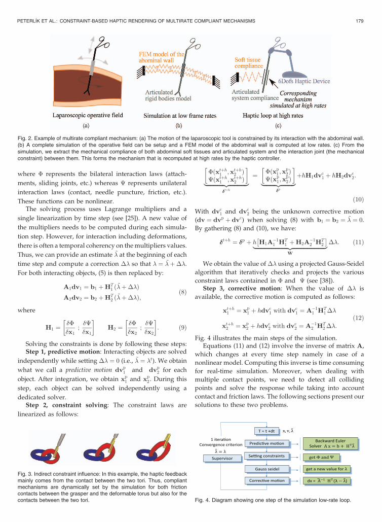
Let us consider the case of a laparoscopic procedure (seeFig. 2). The instruments are inserted through a smallincision in the abdominal wall. They are generallyconsidered as mechanically linked with the operative fieldthrough the insertion point (Fig. 2a), and the design ofdedicated haptic rendering devices often reflects thishypothesis.
In reality, the degrees of freedom of the laparoscopicdevice are constrained by a cylindrical joint correspondingto the trocar that is fixed on the abdominal wall andthrough which the instruments slide. Therefore, a moreaccurate haptic rendering could be computed by modelingthe deformation of the abdominal wall (for instance with aFEM model updated at a low frequency, see Fig. 2b), and bymodeling precisely the interaction, in the one hand betweenthe instrument and the trocar, and in the other hand, theinstrument with the body’s tissues. Then, instead of using adedicated device, we could constrain the motion of ageneric 6DoF haptic device using a compliant mechanism(Fig. 2c). In order to match the mechanical constraintsdescribed in the simulation, this multirate compliantmechanism will act directly on the control of the interface,at high frequency rates.
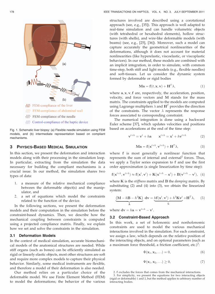
Further, Fig. 1 illustrates how an accurate hapticrendering of the needle insertion can be handled usingmultirate compliant mechanisms: Soft tissue deformationand needle bending are computed in real-time at a lowfrequency (� 30Hz) in one thread, while another threadcomputes at high frequency (> 500Hz) the mechanismsdefined for this problem. As a result, the force felt by theuser describes correctly the interaction of the needle withthe two soft tissues.
Complex interactions, like grasping and suturing, can bemodeled by more complex constraint laws, and/or bycombining several compliant mechanisms together. As anexample, we have shown that the grasping of a deformableobject can be modeled using complementarity constraints[32]. In other cases, it is necessary to combine severaladvanced compliant mechanisms together in order tofeedback the influence of indirect constraints (i.e., constraintsthat are not directly applied to the coupled virtual object asillustrated in Fig. 3).
PETERL�IK ET AL.: CONSTRAINT-BASED HAPTIC RENDERING OF MULTIRATE COMPLIANT MECHANISMS 177
3 PHYSICS-BASED MEDICAL SIMULATION
In this section, we present the deformation and interaction
models along with their processing in the simulation loop.
In particular, extracting from the simulation the data
necessary for building the compliant mechanisms is a
crucial issue. In our method, the simulation shares two
types of data:
1. a measure of the relative mechanical compliancebetween the deformable object(s) and the manip-ulator, and
2. a set of equations which model the constraintsrelated to the function of the device.
In the following sections, we present the deformation
models and their computation in the simulation before the
constraint-based dynamics. Then, we describe how the
mechanical coupling between constraints is computed
using a projected compliance matrix. Finally, we explain
how we set and solve the constraints in the simulation.
3.1 Deformation Models
In the context of medical simulation, accurate biomechani-
cal models of the anatomical structures are needed. While
stiff organs (such as bones) can be efficiently simulated as
rigid or linearly elastic objects, most other structures are soft
and require more complex models to capture their physical
behavior. Similarly, some medical instruments are flexible,
and therefore a model of their deformation is also needed.Our method relies on a particular choice of the
deformable model. We use Finite Element Method (FEM)
to model the deformations; the behavior of the various
structures involved are described using a corotationalapproach (see, e.g., [35]). This approach is well adapted toreal-time simulation and can handle volumetric objects(with tetrahedral or hexahedral elements), hollow struc-tures (with shells), and wire-like deformable models (withbeams) (see, e.g., [25], [36]). Moreover, such a model cancapture accurately the geometrical nonlinearities of thedeformations, although it does not account for materialnonlinearities (like hyperelastic, viscoelastic, or viscoplasticbehaviors). In our method, these models are combined withan implicit integration, in order to simulate, with commontime-step, both stiff and light models (e.g., flexible needles)and soft-tissues. Let us consider the dynamic systemformed by deformable or rigid bodies
Ma ¼ fðt;x;vÞ þHT�; ð1Þ
where a;x;v; f are, respectively, the acceleration, position,velocity, and force vectors and M stands for the massmatrix. The constraints applied to the models are computedusing Lagrange multipliers � and HT provides the directionof the constraints. The vector � represents the responseforces associated to corresponding constraint.
The numerical integration is done using a backwardEuler scheme [37], which updates velocities and positionsbased on accelerations at the end of the time step:
vtþh ¼ vt þ ha xtþh ¼ xt þ hvtþh ð2Þ
Ma ¼ fðxtþh;vtþhÞ þHT�; ð3Þ
where f is most generally a nonlinear function thatrepresents the sum of internal and external2 forces. Thus,we apply a Taylor series expansion to f and use the firstorder approximation (a single linearization by time step):
fðxtþh;vtþhÞ � fðxt;vtÞ þKðxtþh � xtÞ þBðvtþh � vtÞ; ð4Þ
where K is the stiffness matrix and B the damping matrix. Bysubstituting (2) and (4) into (3), we obtain the linearizedsystem:
M� hB� h2K� �|fflfflfflfflfflfflfflfflfflfflfflfflfflfflffl{zfflfflfflfflfflfflfflfflfflfflfflfflfflfflffl}
A
dv ¼ hfðxt;vtÞ þ h2Kvt|fflfflfflfflfflfflfflfflfflfflfflfflfflfflffl{zfflfflfflfflfflfflfflfflfflfflfflfflfflfflffl}b
þHT�; ð5Þ
where dv ¼ ha ¼ vtþh � vt.
3.2 Constraint-Based Approach
In this work, a set of holonomic and nonholonomicconstraints are used to model the various mechanicalinteractions involved in the simulation. For each constraint,we assign a law, which depends on the relative position ofthe interacting objects, and on optional parameters (such asa maximum force threshold, a friction coefficient, etc.)3:
�ðx1;x2; . . .Þ ¼ 0; ð6Þ
�ðx1;x2; . . .Þ � 0; ð7Þ
178 IEEE TRANSACTIONS ON HAPTICS, VOL. 4, NO. 3, JULY-SEPTEMBER 2011
2. f excludes the forces that comes from the mechanical interactions.3. For simplicity, we present the equations for two interacting objects
(rigid or deformable) 1 and 2, but the method applies to arbitrary number ofinteracting bodies.
Fig. 1. Schematic liver biopsy: (a) Flexible needle simulation using FEM
models, and (b) intermediate representation based on compliant
mechanisms.
where � represents the bilateral interaction laws (attach-
ments, sliding joints, etc.) whereas � represents unilateral
interaction laws (contact, needle puncture, friction, etc.).
These functions can be nonlinear.The solving process uses Lagrange multipliers and a
single linearization by time step (see [25]). A new value of
the multipliers needs to be computed during each simula-
tion step. However, for interaction including deformations,
there is often a temporal coherency on the multipliers values.
Thus, we can provide an estimate ~� at the beginning of each
time step and compute a correction �� so that � ¼ ~�þ��.
For both interacting objects, (5) is then replaced by:
A1dv1 ¼ b1 þHT1 ð~�þ��Þ
A2dv2 ¼ b2 þHT2 ð~�þ��Þ;
ð8Þ
where
H1 ¼��
�x1;��
�x1
� �H2 ¼
��
�x2;��
�x2
� �: ð9Þ
Solving the constraints is done by following these steps:Step 1, predictive motion: Interacting objects are solved
independently while setting �� ¼ 0 (i.e., ~� ¼ �t). We obtain
what we call a predictive motion dvp1 and dvp
2 for each
object. After integration, we obtain xp1 and xp
2 . During this
step, each object can be solved independently using a
dedicated solver.Step 2, constraint solving: The constraint laws are
linearized as follows:
�ðxtþh1 ;xtþh2 Þ�ðxtþh1 ;xtþh2 Þ
� �|fflfflfflfflfflfflfflfflfflfflfflfflffl{zfflfflfflfflfflfflfflfflfflfflfflfflffl}
��tþh
¼ �ðxp1 ;x
p2Þ
�ðxp1 ;x
p2Þ
� �|fflfflfflfflfflfflfflfflffl{zfflfflfflfflfflfflfflfflffl}
��p
þhH1dvc1 þ hH2dvc
2:
ð10Þ
With dvc1 and dvc
2 being the unknown corrective motion
(dv ¼ dvp þ dvc) when solving (8) with b1 ¼ b2 ¼ ~� ¼ 0.
By gathering (8) and (10), we have:
��tþh ¼ ��p þ h H1A�11 HT
1 þH2A�12 HT
2
� �|fflfflfflfflfflfflfflfflfflfflfflfflfflfflfflfflfflfflfflfflfflfflfflffl{zfflfflfflfflfflfflfflfflfflfflfflfflfflfflfflfflfflfflfflfflfflfflfflffl}
W
��: ð11Þ
We obtain the value of �� using a projected Gauss-Seidel
algorithm that iteratively checks and projects the various
constraint laws contained in � and � (see [38]).Step 3, corrective motion: When the value of �� is
available, the corrective motion is computed as follows:
xtþh1 ¼ xp1 þ hdvc
1 with dvc1 ¼ A�1
1 HT1 ��
xtþh2 ¼ xp2 þ hdvc
2 with dvc2 ¼ A�1
2 HT2 ��:
ð12Þ
Fig. 4 illustrates the main steps of the simulation.Equations (11) and (12) involve the inverse of matrix A,
which changes at every time step namely in case of a
nonlinear model. Computing this inverse is time consuming
for real-time simulation. Moreover, when dealing with
multiple contact points, we need to detect all colliding
points and solve the response while taking into account
contact and friction laws. The following sections present our
solutions to these two problems.
PETERL�IK ET AL.: CONSTRAINT-BASED HAPTIC RENDERING OF MULTIRATE COMPLIANT MECHANISMS 179
Fig. 3. Indirect constraint influence: In this example, the haptic feedbackmainly comes from the contact between the two tori. Thus, compliantmechanisms are dynamically set by the simulation for both frictioncontacts between the grasper and the deformable torus but also for thecontacts between the two tori.
Fig. 2. Example of multirate compliant mechanism: (a) The motion of the laparoscopic tool is constrained by its interaction with the abdominal wall.
(b) A complete simulation of the operative field can be setup and a FEM model of the abdominal wall is computed at low rates. (c) From the
simulation, we extract the mechanical compliance of both abdominal soft tissues and articulated system and the interaction joint (the mechanical
constraint) between them. This forms the mechanism that is recomputed at high rates by the haptic controller.
Fig. 4. Diagram showing one step of the simulation low-rate loop.

3.3 Compliance Warping
The computation of matrix W in (11) requires thecomputation of the matrix hA�1 for each interacting object.This matrix is homogeneous to a compliance, i.e., theinverse of the stiffness. With deformable objects undergoinglarge displacements, A�1 must be updated when M, K, andB change according to the nonlinear deformations. Thiscomputation can quickly become prohibitive for complexobjects with a large number of degrees of freedom. Toaddress this issue, we use a compliance warping methodproposed in [32] which provides a good approximation ofthe matrix A�1. It is inspired by the corotational model,where the stiffness of each element Ke
0 is computed usinglinear formulation and for each new computation, theupdated matrix Ke is computed as RKe
0R>, where matrix
R is given by the rotation of the element w.r.t. its restposition. Similarly, the method of compliance warping hastwo parts: First, the matrix A�1
0 is precomputed at thebeginning of the simulation. Second, a local evaluation ofthe rotation during the nonlinear deformation is performed.This rotation is approximated at the node level using therotations found on the neighboring elements. Consequently,the compliance matrix is approximated C � hA�1 using:
C ¼ hRA�10 RT ; ð13Þ
where R is a 3� 3 block diagonal matrix that gathers therotations associated with object nodes. This simplificationsignificantly speeds up the computation of the matrixinvolved in (11). The speed-up is enforced by takingbenefit from the sparsity of matrices R (block-diagonalmatrix) and H.
The same approximation is used when applying thecorrective motion, and (12) becomes (for object 1, forinstance):
xtþh1 ¼ xp1 þC HT
1 ��: ð14Þ
If the temporal coherency can apply to the constraint(resting contacts, smooth motions, quasi-static cases, etc.),we can obtain a good prediction of the Lagrange multipliervalue: ~� � �. In such a case, the norm of �� becomes smallcompared to � and the error introduced by the use of thecompliance warping vanishes, as C HT
1 ��! 0.This technique is particularly suitable for real-time
applications: When the computation time is critical (com-plex and nonsmooth events), a fair solution can be obtainedquickly. But in addition, when a good prediction of theconstraint value can be obtained, the solution is veryaccurate. The following section presents how ~� is chosen.
3.4 Supervisor
This subsection presents a small additional contributionthat allows for more accurate use of compliance warpingusing prediction.4 We introduce a supervisor that controlsthe prediction of the Lagrange multipliers depending on thevalue obtained during the previous time steps. Values ofsmooth constraints are nearly consistent from one step toanother. In general, we can use the values �t and �t�h to
compute the approximation ~�. In practice, we apply a lowpass filter (first-order) with a cutoff frequency three timessmaller than the frequency of the simulation. It removesunwanted quick changes of the constraint values due tonumerical errors or due to the coupling with nonsmoothevents. For example, unilateral constraints for restingcontacts have responses with small variations from a stepto another. Consequently, to compute a prediction ~�, we donot record the value of �t0 for the step t0 when the constraintappears (i.e., when � reflects the value of impulse) and weonly compute the prediction if the constraint remains activeafter two steps �t0þ2h > 0. In contrast, temporal consistencydoes not apply in nonsmooth constraints e.g., contact andnoncontact (abrupt change in velocity), static friction, etc.
3.5 Constraints Specific to Medical Instruments
Constraint-based modeling allows simple mechanical mod-eling of tissue-tool interactions. Generic interactions, suchas contact or friction, can be handled this way, but alsomore specific interactions, such as puncture of a needle tipthrough the surface of soft tissues. Each new constraint isdynamically added as a multirate compliant mechanism tobe rendered by the haptic controller, as presented inSection 4. We previously presented the use of constraint-based modeling in [33] for noninteractive modeling (andtherefore no haptic feedback) of complex interactions.Before looking more precisely at haptic rendering, wepresent briefly how a set of constraints can be used tophysically model the interactions between instruments andorgans.
3.5.1 Mapping of Constraint Points
Our method allows for defining constraints between pointsbelonging to the interacting bodies. This constraint position-ing does not necessarily correspond to existing degrees offreedom. Fig. 5 shows that we can set a constraint between apoint P and a point Q attached anywhere to object 1 andobject 2, respectively.
If any constraint � or � is defined between those points,along a constraint direction n, the formulation will rely on amapping function (a simple example of such a mapping isan interpolation function, but more complex mappings canbe defined). Hence, the variation of the constraint value,denoted �� (¼ �� or ¼ ��) can be mapped on thedisplacements of models 1 (�x1) and model 2 (�x2) using:
�� ¼ nT ðu� vÞ ¼ nT ðJ1�x1 � J2�x2Þ¼ H1�x1 þH2�x2:
ð15Þ
180 IEEE TRANSACTIONS ON HAPTICS, VOL. 4, NO. 3, JULY-SEPTEMBER 2011
Fig. 5. Constraint between two mapped points. The displacement uof the first point (placed inside a tetrahedral volume model) is given bythe barycentric coordinates J1 and the displacement �x1 of the 4 nodesu ¼ J1�x1. The displacement of the second point v on a beam model ismapped using the interpolation of the beam deformation modelv ¼ J2�x2.
4. We emphasize that this part is not required, and if no prediction isused ( ~� ¼ 0), the method presented in this paper still holds.

3.5.2 Sliding
Several types of instruments require sliding constraints tomodel their interactions. For instance, the insertion of aflexible needle through soft tissues can be modeled as aseries of bilateral constraints between serially connectedbeams (for the flexible needle) and a volumetric model (forthe soft tissue). The constraints are sampled using slidingpoints constraints. These constraints � cancel the relativemotion in the normal directions between the needle and thesoft-tissue, as described in [33]. This type of modeling couldalso be used for other application such as the insertion of alaparoscopic instrument through a trocar, as mentioned inSection 2.3.
3.5.3 Contact
A model based on unilateral constraint is essential to obtainboth realistic behavior and convincing haptic feedback ofcontact, in surgery simulation. When an instrument createsdeformations on soft tissues, it modifies the boundaryconditions of the model and will mainly modify itsbehavior. Moreover, contact between other bodies can alsomodify indirectly the force feedback (see Fig. 3).
Contacts are detected using proximity queries betweeninteracting bodies. The advantage of proximity overcollision detection is that we can anticipate the contactand provide the unilateral compliant mechanism to thehaptic control prior to contact activation in the simula-tion. The contact law 0 � �ðx1;x2Þ ? �c � 0 follows theSignorini’s law.
3.5.4 Friction
The two previous types of constraint (sliding and contact)can be combined with friction. The modeling of frictionrelies on Coulomb’s law which defines two states: adher-ence (stick) when there is no relative motion �f ¼ 0 due tostatic friction and dynamic friction (slip) when the relativemotion is not null �f 6¼ 0.
A threshold �:p is used to limit the adherence: � is thecoefficient of friction and p is the pressure exerted on thesliding or contact constraint direction. In case of frictioncontact, p ¼ �c if �c represents the reaction computed by theSignorini’s law. For solving friction contact, see [25].
In the case of sliding, when a needle is inserted insidesoft tissues, p is the pressure exerted by the soft tissue onthe needle. Currently, this constant pressure is estimatedfrom the stiffness of the soft tissue. We use stress measuresto model it more accurately. Fig. 6 shows the value of thefriction resistance r integrated along the inserted surface ofthe needle. Each constraint point owns a part of the needlecurve and computes the friction force by using the length l
of this curve part (�f ¼ l�d:r where d is the diameter of thecross-section).
3.5.5 Specific Constraints for Needle Insertion
Several specific constraints are applied to the needle. First,when the needle punctures the surface of the soft-tissue, adiscontinuity in the interaction force is observed. Moreover,if the tissue varies in stiffness (around certain types oftumors, for instance), the tip of the needle is sometimesdeflected from the stiff zone.
We model this as a contact constraint (like in Sec-tion 3.5.3) between the needle tip and the tissue surface, butaugmented with a force threshold beyond which the needlepenetrates (see Fig. 7). Different values for a threshold fpcan be defined in order to simulate different tissuebehaviors. So, the puncture constraint can be appliedseveral times during the simulation if the needle passesthrough different tissue layers.
The modeling of the cutting force fc at the needle tip isalso necessary when penetrating a tissue structure. Themodeling is similar to the puncture constraint and fc can betuned to different values from a layer to another. This forcedisappears if the needle is reinserted at the same location.
4 HAPTIC RENDERING
4.1 Setting Mutirate Mechanisms
Interactive medical simulations using accurate deformableand complex interaction models can hardly run at hapticrefresh rates in the same loop. In general, the refresh rate ofthese simulations range typically between 30 Hz and 60 Hz(vision rendering rates). Therefore, haptic feedback iscomputed in a separate loop which runs at faster rates(� 500 Hz) and relies on an intermediate representation.
In the previous section, we emphasized the importanceof an accurate modeling of the mechanical interactionsbetween surgical instruments and soft-tissues. The trans-mission models of the force and/or the motion betweeninteracting bodies are the key for realistic simulation andfor high fidelity haptic rendering. Thus, we propose toshare these models computed in the simulation with thehaptic control loop in a unified formalism called multiratecompliant mechanisms. Indeed, these compliant mechan-isms will serve as an intermediate representation in order tobe recomputed, at high rates in the haptic loop. This workhas similarities with the work in [32]. It can be seen as itsgeneralization, since [32] is limited to contact interactions.
PETERL�IK ET AL.: CONSTRAINT-BASED HAPTIC RENDERING OF MULTIRATE COMPLIANT MECHANISMS 181
Fig. 6. Static and dynamic friction are included. Fig. 7. Puncture constraint. Q is the tip of the needle and P is thecontacting point (or the penetration point) on the tissue surface. Duringstep 1, Q is only approaching the tissue surface. The gap � is positive(�p � 0) and the interaction force must be null (�p ¼ 0). During step 2, Qis touching without puncturing the tissue surface. The gap between Pand Q is null (�p ¼ 0) and the interaction force is necessarily positive inthe direction of the surface normal (�p � 0). The value of this force isstrictly less than a puncturing force threshold �p � fp. During step 3, theneedle tip enters in the tissue, the gap along the constraint direction isnegative (�p � 0) and the constraint force is equal to the threshold(�p ¼ fp).

The definition of the intermediate representation basedon compliant mechanisms relies on:
1. the constraints � or � and their value during thepredictive motion �P , and
2. the compliance of the simulated models given by(11).
Note that the same mechanisms are computed in thesimulation and in the haptic loop. There is no modelsimplification or reduction to provide the user with highquality haptic rendering. As mentioned previously, ourmethod can be used also for stiff contacts. However, in thiscase, the haptic rendering can become instable due to themechatronic characteristics of the haptic display device,e.g., limited actuator torques, bandwidth and latency of thecontrol loop. To address this issue, a 6DoF control spring isplaced between the device position and the virtual positionused in the simulation (see Fig. 8). The coupling betweenthe control spring and the flexible virtual device is doneusing a coupling mechanism, i.e., a fixed joint preventing thetwo objects from any relative motion. The couplingmechanism is composed of the 6DoF bilateral constraintand the compliance value of both control spring and flexibleinstrument.
Given this set of constraints and a constraint solver (e.g.,a projected Gauss-Seidel), the corresponding constraintresponses �� can be computed as shown in Section 3.2. Asthe real compliance of the objects is used, the contactresponse �C associated to the coupling constraint intro-duced above equilibrates the response forces induced byother constraints involved in the simulation. Further, thevalue �C is used as the haptic feedback force applied to theinterface.
fh ¼ ��C: ð16Þ
Consequently, the calculation of the haptic force relies onupdating the compliant mechanisms. Performing an update
only in the simulation loop, at low rate, would result in adegradation of the haptic response. However, as statedbefore, the compliant mechanisms are shared between thesimulation and the haptic loops: In each step of thesimulation, the compliant mechanisms are evaluated usingthe actual constraint violations and the correspondingresponse force is computed. In the haptic loop, a newposition xH
C of the control spring is computed given theactual position of the haptic device. Afterwards, theconstraint violation ��P is updated using xH
C and predictiveposition xP computed in the previous simulation step:
��PC ¼ ��P
C þHCðxHC � xP
CÞ: ð17Þ
Due to the change in the constraint violation ��P, theresponse vector � must be updated in the haptic loop.
Note that the constraint law defined for each mechanismis fulfilled for the haptic rendering. Let’s take the exampleof a contact compliant mechanism: When the mechanism isset in the simulation, the objects are not necessarilycontacting, as we use proximity detection. If the hapticdevice is not moved, the distance between objects remainspositive and no contact forces are sent to the interface. But,if the user moves towards a contact, the constraint solverwill detect an interpenetration � < 0 and will send apositive contact force � > 0 to the haptic device. Thisbehavior conforms the Signorini’s law at high rates, when acontact is detected in the simulation.
Yet, the computation time induced by the resolution ofthe constraint problem can exceed the time allotted to onehaptic step. Fortunately, the simulation also needs to solvethe same mechanisms. Subsequently, the physics loop canobtain a solution before sharing. This solution constitutes agood initial guess for the similar constraint problem in thehaptic loop insofar as displacements of the user are not toolarge between two simulation steps. By using this solutionas a warm start in the haptic constraint solver, we noticedthat the convergence is usually reached very quickly.However, as in [32], we modify the Gauss-Seidel algorithmin the haptic loop so that it always stops the iterations after1 or 2 ms.
4.2 Haptic Control Implementation
Setting the appropriate constraints in the simulation createsthe multirate compliant mechanisms. Concretely, thesemechanisms are programmed as instantiations of the objectclass multirateSimulatedMechanisms which contains thefollowing methods:
. Vector �� ¼ EvaluateConstraintðx1;x2Þ. Dependingof the type of constraints, this function providesthe value of �ðx1;x2Þ or �ðx1;x2Þ.
. Vector ��iþ1 ¼ SolveConstraintð��i;W; �iÞ. Thisfunction is called during the Gauss Seidel iterativeprocess. For a given values of � and � at iteration iand the matrix W, it computes a correction ��iþ1 sothat the constraint is satisfied.
. SparseMatrix H = getH(intidObject) provides thematrix H on the constraint for any object in thesimulation.
. indexVector rowsInd = getRows() gives the rowsindices of the mechanism’s constraints in vector ��.
182 IEEE TRANSACTIONS ON HAPTICS, VOL. 4, NO. 3, JULY-SEPTEMBER 2011
Fig. 8. Haptic force computation. Above: the compliant mechanisms arecomputed and solved in the simulation. The response force �Cassociated to the coupling compliant mechanism balances the reactioncomputed on other mechanisms (here �1 and �2). Below: At high rates,(1) The 6DoFs control spring is recomputed and provides a new positionxH
C for the coupling point. (2) The constraints are updated given this newposition. (3) The reaction force �3 is the opposite of the force that is sentto the user by the haptic device.

Simulated mechanisms are shared with the haptic loop
using a double buffer system: There are two lists containing
the instance of this class. When the simulation is writing on
one list, the haptic loop has a read access on the other list.The solving process of the multirate compliant mechan-
isms should provide new values of � which correspond to
their response to the given solicitation. In our work, we find
new value for � using a generic Gauss-Seidel algorithm
(Algorithm 1) that iterates until a time limit is over. For the
sake of completeness, we briefly describe the implementa-
tion, which is very simple. Basically, any other constraint
solver can be used instead.
In order to meet time constraints in the haptic loop, we
limit the amount of computation that is performed at each
time step. We concentrate the computational effort towards
obtaining the most accurate evaluation of the multirate
mechanisms response given a sampling time of the device
position.The evaluation of the coupling-constraint violation is done
by the simulation at position xPC using EvaluateConstraint on
each multirate mechanism. The haptic loop begins with an
update of the control spring position xHC (subsequent to the
user desired motion) which is followed by an update
coupling-constraint using (17).Then, we call the Gauss-Seidel algorithm (Algorithm 1)
described above which takes almost the entire time allotted
to the computation of the haptic rendering. The haptic loop
(Algorithm 2) computes the force, (16), which is sent to the
haptic display device.
5 RESULTS AND DISCUSSION
5.1 Needle Insertion
To assess our approach, we performed an interactive force-
feedback needle insertion task. As introduced in Section 3.1,
the corotational models were used for both the needle and
the concerned objects. We set a Young modulus
E ¼ 9:1013 Pa for the needle, E ¼ 10; 000 Pa for the object
to be punctured and a Poisson ratio � ¼ 0:40 for all.Two different scenarios were considered. First, the
needle is inserted into a homogeneous phantom cube in
order to reproduce the existing experiment described in [39]
and compare our obtained force profile. Second, real-time
simulation of the liver biopsy was performed showing that
the method allows for simulation of multiple objects which
provides different types of constraints.
PETERL�IK ET AL.: CONSTRAINT-BASED HAPTIC RENDERING OF MULTIRATE COMPLIANT MECHANISMS 183
Fig. 9. Communication between haptic and simulation loops.
The needle simulation experiments enabled us to
evaluate several aspects of our method. First, we analyzethe force feedback profile obtained from the haptic loop andwe discuss the qualitative behavior of the needle simula-tion. Second, we examine the stability and the accuracy ofthe haptic rendering observed during the interaction.
5.2 Assessing the Force Feedback Profile
First, using force profiles, the realism of the simulation has
been compared to experimental studies performed on aphantom model. Further, the behavior of the simulation aswell as the precision of the haptic rendering have beenstudied w.r.t. the number of the constraints actuallyinvolved in the simulation.
To assess the quality of the simulation, the force profilewas studied for the case when a needle is inserted into a
three-dimensional soft tissue model and pulled back multi-ple times. This was done for a simple cubic tissue samplepresented in Fig. 10. The tip of the needle was chosen as theoperational point. The resulting force profile is depicted inFig. 10, showing the force evolution w.r.t. the position of theoperation point. Particular phases of the insertion processcan be described as follows:
1. The needle is outside the deformable body, no forcesare applied.
2. After penetration the surface of the tissue (force peakbetween phases 1 and 2), the needle is being insertedinto the body. Two different forces are applied:cutting force and friction.
3. The needle is pulled back, only friction is applied (inthe opposite direction w.r.t. the motion).
4. The needle is inserted again, following the samepath as before; since there is already a puncture pathfrom previous insertion, no cutting force is presentand only the friction acts.
It can be observed that during repeated needle insertion(starting with phase 4), only friction is applied when goingthrough the puncture path which has been already cutbefore. However, as soon as the extreme point of previousinsertion is reached, the cutting force appears again(phase 3). The profile is clearly similar to the experimentalresults reported in [39].
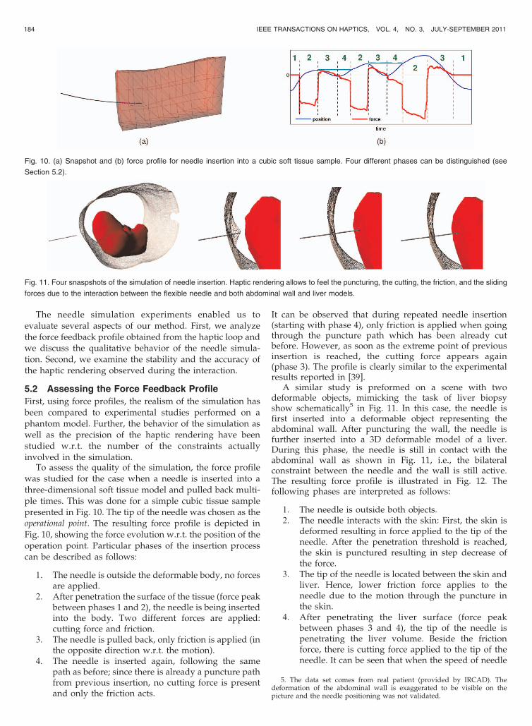
A similar study is preformed on a scene with twodeformable objects, mimicking the task of liver biopsyshow schematically5 in Fig. 11. In this case, the needle isfirst inserted into a deformable object representing theabdominal wall. After puncturing the wall, the needle isfurther inserted into a 3D deformable model of a liver.During this phase, the needle is still in contact with theabdominal wall as shown in Fig. 11, i.e., the bilateralconstraint between the needle and the wall is still active.The resulting force profile is illustrated in Fig. 12. Thefollowing phases are interpreted as follows:
1. The needle is outside both objects.2. The needle interacts with the skin: First, the skin is
deformed resulting in force applied to the tip of theneedle. After the penetration threshold is reached,the skin is punctured resulting in step decrease ofthe force.
3. The tip of the needle is located between the skin andliver. Hence, lower friction force applies to theneedle due to the motion through the puncture inthe skin.
4. After penetrating the liver surface (force peakbetween phases 3 and 4), the tip of the needle ispenetrating the liver volume. Beside the frictionforce, there is cutting force applied to the tip of theneedle. It can be seen that when the speed of needle
184 IEEE TRANSACTIONS ON HAPTICS, VOL. 4, NO. 3, JULY-SEPTEMBER 2011
5. The data set comes from real patient (provided by IRCAD). Thedeformation of the abdominal wall is exaggerated to be visible on thepicture and the needle positioning was not validated.
Fig. 10. (a) Snapshot and (b) force profile for needle insertion into a cubic soft tissue sample. Four different phases can be distinguished (see
Section 5.2).
Fig. 11. Four snaspshots of the simulation of needle insertion. Haptic rendering allows to feel the puncturing, the cutting, the friction, and the sliding
forces due to the interaction between the flexible needle and both abdominal wall and liver models.

motion is reduced, the cutting forces decreasesrapidly.
5. The needle is being pulled back. Therefore, onlyfriction acts on the needle.
It should be mentioned that the force profile was acquiredduring the real interaction with the needle (i.e., the needlewas driven by a haptic device controlled by user). There-fore, the trajectory of the needle was not ideally straight andthe force response in some phases is affected by lateralforces and deformation of the objects being penetrated.Nevertheless, we believe that the profile confirms theground-truth of the model.
5.3 Stability and Accuracy of Haptic Rendering
As described in Section 4.1, the frequency of the haptic loopcan be guaranteed by setting the time limitation of thetimed Gauss-Seidel method to sufficiently short period.Subsequently, the convergence of the method can becompromised due to time limitation. Such a behavior canbe minimized because of two reasons: First, the constraintresolution computed by the full Gauss-Seidel method in thelast step of the simulation loop is used as the initialestimation for the timed Gauss-Seidel method performed inthe haptic loop. Second, if the motion of the haptic device isquite slow w.r.t. the refresh rate of the simulation loop, thesolution provided by full Gauss-Seidel method does notvary too fast. Hence, it can be assumed that the convergenceof the timed Gauss-Seidel method can be achieved in alimited amount of iterations as long as the simulation loopruns on sufficiently high frequency and provides goodinitial guesses.
In order to determine a lower bound of the simulationfrequency, we performed an interactive simulation ofneedle insertion on machine equipped with Intel XeonW2550 CPU Processor running at 3.0 GHz and 6 GB RAM.Two objects were involved in the interaction: a deformablecube (with about 250 elements) and deformable needle(40 beam elements). The number of constraints along theneedle path could be adjusted to obtain a realistic behaviorduring the interaction.
According to our experimental studies, the thresholdfrequency of the simulation loop is about 30 Hz, whichcould be sustained for up to 120 contacts between theneedle and the cube. If simulation is running at a frequencysuperior to this threshold, both stability and accuracy of theinteraction is guaranteed. However, for lower frequencies,the interaction becomes instable and inaccurate. It can beexplained by two factors: First, the timed Gauss-Seidelmethod does not give reliable results as the initial guessprovided by the full Gauss-Seidel method is too far from the
optimal solution associated with the actual position of thehaptic device. Second, the constraints are created with adelay that leads to visually inconsistent simulation.
5.4 Discussion
The main advantage of our approach is to have an accurateintermediate representation of the deformation in the hapticloop. Indeed, the inverse of matrix A is used to compute aconstraint-based response. This matrix is related to mechan-ical properties (stiffness, mass, and damping) of theinteracting virtual objects (see Section 3.1). Also, we use afully implicit integration scheme which allows for large timestep and results in stable simulation.
The notion of large time step is ambiguous. As shown inthe previous section, the stability of haptic rendering can beaffected by the duration of the time step. Therefore, weshortly discuss the main factors that lead the choice of thetime step.
First, the time step is highly constrained by the complex-ity of the model computation which is given by the size ofthe deformable meshes and the number of constraints. Forboth cases, optimal values of the time-step can bedetermined for a given hardware configuration and aknown simulation scenario.
Second, the calculations performed within the simulationstep are influenced by mechanical properties of the objectsbeing simulated. In the case of soft tissues, this is usuallynot a problem as the organs are usually soft but quite heavy.Nevertheless, in cases when the manipulator is stiff butvery lightweight (such as needle), the resulting systemmatrix is badly-conditioned and, thus, the contact resolu-tion may become computationally unstable. For the actualexperiments, we tuned the system parameters to obtainnumerically stable calculations. This issue may be solved byassigning a rigid mass to the needle and by computing thedeformation using a quasi-static approach. This could bedone with a generalization, to nonlinear deformations, ofthe corotational global approach described in [25].
6 CONCLUSION AND FUTURE WORK
In the paper, we devised a method allowing for hapticrendering of complex interactions between various medicaldevices and anatomical structures. First, we introduced ageneric formalism for modeling complex interactionsbetween deformable objects. Our formalism presents anintermediate representation based on multirate compliantmechanisms. Second, constraint-based rendering methodhas been presented for solving this intermediate represen-tation. The method relies on realistic constraint resolutiondirectly employing the compliance of the objects involvedin the interaction. To achieve the haptic rates, the mechan-isms are set and solved in the simulation and then sharedwith a separate high-rate loop. The constraint response ofthe multirate compliant mechanisms representation is thenupdated in each step of the haptic loop according to theactual position of the interface, resulting in fast, stable inpractice and accurate rendering.
To assess our approach, a simulation of needle insertionis presented for two different scenarios. The correspond-ing force profiles are recorded; they proved to be accurateand similar to profiles reported elsewhere. The genericityof multirate compliant mechanisms-based approach is
PETERL�IK ET AL.: CONSTRAINT-BASED HAPTIC RENDERING OF MULTIRATE COMPLIANT MECHANISMS 185
Fig. 12. Force profile for insertion of needle into liver through skin. Five
different phases are distinguished (see Section 5.2).

demonstrated using a simulation where the deformableneedle interacts with two soft organs. For the perfor-mance, it was observed that for the given scenario, up to120 constraints can be handled on single PC.
The method can be used also by another application;currently, we investigate the haptic rendering of suturing.As a future work, we will focus on the extension of themethod in order to address the topological changes such ascutting. In this case study, the value of the compliancecannot be precomputed and warped; in addition, thecompliance may change between two steps of the hapticloop. Additionally, a stability study will be thoroughlyconducted. It should be demonstrated that the renderingmethod being proposed always dissipates the energy,which would lead to verification of the passivity conditionsthat can even be integrated as part of the solver. Finally, weplan to further investigate the possibility of extending theapproach beyond the use of a corotational finite elementmethod, for instance with fully nonlinear models to graspmore accurately the behavior of soft tissues.
ACKNOWLEDGMENTS
The authors would like to thank G. Saupin andC. Guebert for their previous contributions which havelead to the idea presented in this paper. This work hasbeen developed using the Open Source SOFA framework(www.sofa-framework.org).
REFERENCES
[1] A.G. Gallagher, A.B. Lederman, K. McGlade, R.M. Satava, andC.D. Smith, “Discriminative Validity of the Minimally InvasiveSurgical Trainer in Virtual Reality (MIST-VR) Using CriteriaLevels Based on Expert Performance,” Surgical Endoscopy, vol. 18,pp. 660-665, 2004.
[2] T.S. Desser, “Simulation-Based Training: The Next Revolution inRadiology Education?” J. Am. College of Radiology, vol. 4, no. 11,pp. 816-824, 2007.
[3] H. Courtecuisse, H. Jung, J. Allard, C. Duriez, D.Y. Lee, and S.Cotin, “GPU-Based Real-Time Soft Tissue Deformation withCutting and Haptic Feedback,” “Progress in Biophysics andMolecular Biology, special issue on soft tissue modelling, to appear.
[4] Z. Taylor, O. Comas, M. Cheng, J. Passenger, D. Hawkes, D.Atkinson, and S. Ourselin, “Modelling Anisotropic Viscoelasticityfor Real-Time Soft Tissue Simulation,” Proc. Medical ImageComputing and Computer-Assisted Intervention (MICCAI ’08X),pp. 703-710, 2008.
[5] S. Marchesseau, T. Heimann, S. Chatelin, R. Willinger, and H.Delingette, “Multiplicative Jacobian Energy Decomposition Meth-od for Fast Porous Visco-Hyperelastic Soft Tissue Model,” Proc.Medical Image Computing and Computer Assisted Intervention(MICCAI ’10), Sept. 2010.
[6] J. Colgate, M. Stanley, and J. Brown, “Issues in the Haptic Displayof Tool Use,” Proc. IEEE/RSJ Int’l Conf. Intelligent Robots andSystems, vol. 3, p. 3140, 1995.
[7] C.B. Zilles and J.K. Salisbury, “A Constraint-Based God-ObjectMethod for Haptic Display,” IROS ’95: Proc. Int’l Conf. IntelligentRobots and Systems, vol. 3, p. 3146, 1995.
[8] D.C. Ruspini, K. Kolarov, and O. Khatib, “The Haptic Display ofComplex Graphical Environments,” SIGGRAPH ’97: Proc. 24thAnn. Conf. Computer Graphics and Interactive Techniques, pp. 345-352, 1997.
[9] R.J. Adams, M.R. Moreyra, and B. Hannaford, “Stability andPerformance of Haptic Displays: Theory and Experiments,” Proc.ASME Int’l Mechanical Eng. Congress and Exhibition, pp. 227-234,1998.
[10] R.J. Adams, B. Hannaford, M. Ieee, and M. Ieee, “Control LawDesign for Haptic Interfaces to Virtual Reality,” IEEE Trans.Control Systems Technology, vol. 10, pp. 3-13, 2002.
[11] M. Ortega, S. Redon, and S. Coquillart, “A Six Degree-of-FreedomGod-Object Method for Haptic Display of Rigid Bodies withSurface Properties,” IEEE Trans. Visualization and ComputerGraphics, vol. 13, no. 3, pp. 458-469, 2007.
[12] A. Nahvi, D.D. Nelson, J.M. Hollerbach, and D.E. Johnson,“Haptic Manipulation of Virtual Mechanisms from MechanicalCAD Designs,” Proc. IEEE Conf. Robotics and Automation, pp. 375-380, 1998.
[13] D. Constantinescu, S.E. Salcudean, and E.A. Croft, “HapticManipulation of Serial-Chain Virtual Mechanisms,” J. DynamicSystems, Measurement, and Control, vol. 128, no. 1, pp. 65-74, 2006.
[14] L.D. Joly and C. Andriot, “Imposing Motion Constraints to a ForceReflecting Telerobot through Real-Time Simulation of a VirtualMechanism,” Proc. IEEE Int’l Conf. Robotics and Automation, vol. 1,pp. 357-362, 1995.
[15] K. Kosuge, T. Itoh, T. Fukuda, and M. Otsuka, “Tele-ManipulationSystem Based on Task-Oriented Virtual Tool,” Proc. IEEE Conf.Int’l Robotics and Automation, vol. 1, pp. 351-356, 1995.
[16] M. Beenakkers, D. Constantinescu, and M. Steinbuch, “HapticManipulation of Virtual Linkages with Kinematic Loops,” Proc.IEEE/ASME Int’l Conf. Advanced Intelligent Mechatronics, pp. 1-6,2007.
[17] X. Merlhiot, “Une Contribution Algorithmique aux outils deSimulation Mcanique Interactive Pour la Maquette NumriqueIndustrielle,” PhD dissertation, Universite Pierre et Marie Curie,written in English, 2009.
[18] M. Bro-Nielsen and S. Cotin, “Real-Time Volumetric DeformableModels for Surgery Simulation Using Finite Elements andCondensation,” Computer Graphics Forum, vol. 15, no. 3, pp. 57-66, 1996.
[19] S. Cotin, H. Delingette, and N. Ayache, “Real-Time ElasticDeformations of Soft Tissues for Surgery Simulation,” IEEE Trans.Visualization and Computer Graphics, vol. 5, no. 1, pp. 62-73, Jan.-Mar. 1999.
[20] D.C. Popescu and M. Compton, “A Model for Efficient andAccurate Interaction with Elastic Objects in Haptic VirtualEnvironments,” GRAPHITE ’03: Proc. First Int’l Conf. ComputerGraphics and Interactive Techniques in Australasia and South EastAsia, pp. 245-250, 2003.
[21] M. Sedef, E. Samur, and C. Basdogan, “Real-Time Finite-ElementSimulation of Linear Viscoelastic Tissue Behavior Based onExperimental Data,” IEEE Computer Graphics and Applications,vol. 26, pp. 58-68, 2006.
[22] I. Peterlık, M. Sedef, C. Basdogan, and L. Matyska, “Real-TimeVisio-Haptic Interaction with Static Soft Tissue Models HavingGeometric and Material Nonlinearity,” Computers & Graphics,vol. 34, no. 1, pp. 43-54, 2010.
[23] D.L. James and D.K. Pai, “A Unified Treatment of ElastostaticContact Simulation for Real Time Haptics,” Proc. SIGGRAPH ’05:ACM SIGGRAPH 2005 Courses, p. 141, 2005.
[24] J. Barbic and D.L. James, “Six-DoF Haptic Rendering of Contactbetween Geometrically Complex Reduced Deformable Models,”IEEE Trans. Haptics, vol. 1, no. 1, pp. 39-52, Jan.-Mar. 2008.
[25] C. Duriez, F. Dubois, A. Kheddar, and C. Andriot, “RealisticHaptic Rendering of Interacting Deformable Objects in VirtualEnvironments,” IEEE Trans. Visualization and Computer Graphics,vol. 12, no. 1, pp. 36-47, 2006.
[26] Y. Adachi, T. Kumano, and K. Ogino, “Intermediate Representa-tion for Stiff Virtual Objects,” Proc. Virtual Reality Ann. Int’l Symp.(VRAIS ’95), pp. 203-210, 1995.
[27] W.R. Mark, S.C. Randolph, M. Finch, J.M. Van Verth, and R.M.Taylor II, “Adding Force Feedback to Graphics Systems: Issuesand Solutions,” Proc. Conf. Computer Graphics and InteractiveTechniques, pp. 447-452 1996.
[28] C. Garre and M.A. Otaduy, “Haptic Rendering of ComplexDeformations through Handle-Space Force Linearization,” Proc.World Haptics Conf., pp. 422-427, 2009.
[29] C. Forest, H. Delingette, and N. Ayache, “Surface Contact andReaction Force Models for Laparoscopic Simulation,” MedicalSimulation, Lecture Notes in Computer Science, S. Cotin andD. Metaxas, eds., vol. 3078, pp. 168-176, Springer, 2004.
[30] M.A. Otaduy and M. Gross, “Transparent Rendering of ToolContact with Compliant Environments,” WHC ’07: Proc. SecondJoint EuroHaptics Conf. and Symp. Haptic Interfaces for VirtualEnvironment and Teleoperator Systems, pp. 225-230, 2007.
[31] C. Garre and M.A. Otaduy, “Toward Haptic Rendering of Full-Hand Touch,” Proc. CEIG (Spanish Computer Graphics Conf.), 2009.
186 IEEE TRANSACTIONS ON HAPTICS, VOL. 4, NO. 3, JULY-SEPTEMBER 2011

[32] G. Saupin, C. Duriez, and S. Cotin, “Contact Model for HapticMedical Simulations,” ISBMS ’08: Proc. Fourth Int’l Symp.Biomedical Simulation, pp. 157-165, 2008.
[33] C. Duriez, C. Guebert, M. Marchal, S. Cotin, and L. Grisoni,“Interactive Simulation of Flexible Needle Insertions Based onConstraint Models,” Proc. Int’l Conf. Medical Image Computing andComputer-Assisted Intervention (MICCAI ’09), pp. 291-299, 2009.
[34] S.P. DiMaio and S.E. Salcudean, “Needle Steering and Model-Based Trajectory Planning,” Proc. Int’l Conf. Medical ImageComputing and Computer-Assisted Intervention (MICCAI ’03),pp. 33-40, 2003.
[35] J.S. Przemieniecki, Theory of Matrix Structural Analysis. McGrawHill, 1968, 1985.
[36] C. Duriez, S. Cotin, J. Lenoir, and P.F. Neumann, “NewApproaches to Catheter Navigation for Interventional RadiologySimulation,” Computer Aided Surgery, vol. 11, pp. 300-308, 2006.
[37] D. Baraff and A. Witkin, “Large Steps in Cloth Simulation,” Proc.ACM SIGGRAPH ’98, 1998.
[38] C. Duriez, C. Guebert, M. Marchal, S. Cotin, and L. Grisoni,“Interactive Simulation of Flexible Needle Insertions Based onConstraint Models,” Proc. Int’l Conf. Medical Image Computing andComputer-Assisted Intervention (MICCAI ’09), pp. 291-299, Sept2009.
[39] E. Dehghan, X. Wen, R. Zahiri-Azar, M. Marchal, and S.Salcudean, “Needle-Tissue Interaction Modeling Using Ultra-sound-Based Motion Estimation: Phantom Study,” Computer AidedSurgery, vol. 13, no. 5, pp. 265-280, 2008.
Igor Peterlık received the master and PhDdegrees in informatics from Masaryk Univer-sity, Czech Republic. He worked as amember of the Data–Algorithms–Decisionmaking research center at the Academy ofSciences of the Czech Republic. Currently, heis a postdoctoral fellow at INRIA-Lille, Nord-Europe, France. His research interests includecomputer haptics, numerical methods, physi-cally-based simulations, image reconstruction,
and parallel and distributed computing.
Mourad Nouicer received the bachelor ofengineering and master of science (MSc)degrees both from the Military PolytechnicSchool, Algiers, Algeria. He is currently a PhDcandidate in computer science at the InstitutNational d’Informatique, Algiers, Algeria. Hisresearch interests include collision detection,computer haptics, and physically-based simula-tion. In 2009, he was a visiting scholar at INRIA-Lille, Nord-Europe, France, for six months.
Christian Duriez received the engineeringdegree from the Institut Catholique d’Arts etMtiers of Lille, France, and the PhD degree inrobotics from University of Evry, France. Histhesis work was realized at CEA/Robotics andInteractive Systems Technologies followed by apostdoctoral position at the CIMIT SimGroup inBoston. He arrived at INRIA five years ago andhe is now the vice-head of the SHAMAN team.He is also the scientific coordinator of a national
initiative for research on medical simulation around the frameworkSOFA (www.sofa-framework. org). His research work concerns physics-based simulations computed in real-time and haptic rendering formedical applications.
Stephane Cotin is a senior research scientist atINRIA since 2007 where he leads the SHAMANteam. Before joining INRIA, he worked asresearch lead for the Medical Simulation Groupat CIMIT in Boston, Massachussetts, where hewas responsible for defining research directionsand technical infrastructures for several simula-tion projects. His current research interestscover many aspects of numerical medicine, fromtraining to planning and guidance of complex
interventions. In particular, he is involved in research on contactmodeling and biomechanical modeling, in a context where computationtime is a major constraint. He is also leading a national initiative onmedical simulation involving several research groups at INRIA and heinitiated the development of the SOFA framework (www.sofa-frame-work.org). He is author or coauthor of more than 50 conference andjournal articles, and was the organizer of ISBMS 2004, and co-organizerof ISBMS 2010.
Abderrahmane Kheddar received the inge-nieur degree from the Institut National d’Infor-matique (INI), Algiers, and the DEA (Master byresearch) and PhD degree in robotics, both fromthe University of Paris 6, Paris. He is currentlydirecteur de recherche at CNRS and the directorof the CNRS-AIST Joint Robotic Laboratory,UMI3218/CRT, Tsukuba, Japan, a full fledgedinternational mixed unit (UMI) that he created inDecember 2008. He is also leading the Inter-
active Digital Human team at CNRS-UM2 LIRMM, Montpellier, France.Prior to that, he was successively an assistant professor (1998-2002)and then a tenured professor (2003-2008) at the University of �Evry,France. His research interests include collision detection, haptics, andhumanoids. He is a founding member and a senior advisor of the IEEE/RAS chapter on haptics and was with the editorial board of the IEEETransactions on Haptics (2007-2010); he is presently an associateeditor of the IEEE Transactions on Robotics and the Journal ofIntelligent and Robotic Systems. He is a member of the IEEE, OHBM,and the EuroHaptics Society. He was the general chair of the of theEuroHaptics 2006 conference.
. For more information on this or any other computing topic,please visit our Digital Library at www.computer.org/publications/dlib.
PETERL�IK ET AL.: CONSTRAINT-BASED HAPTIC RENDERING OF MULTIRATE COMPLIANT MECHANISMS 187
Copyright © 2022 FDOKUMEN