STEP-NC-Compliant Implementation to Support Mixed ... - MDPI
18
Machines 2021, 9, 327. https://doi.org/10.3390/machines9120327 www.mdpi.com/journal/machines Article STEP‐NC‐Compliant Implementation to Support Mixed‐Control Technologies Applied to Stone‐Processing Machines Based on Industrial Automation Standards Julio Garrido *, Diego Silva and Juan Sáez Automation and System Engineering Department, School of Industrial Engineering, Campus Lagoas Marcosende, Universidade de Vigo, 36310 Vigo, Spain; [email protected] (D.S.); [email protected] (J.S.) * Correspondence: [email protected]; Tel.: +34‐986‐812‐610 Abstract: STEP‐NC (Standard for the Exchange of Product Model Data–Numerical Control) for metal milling and turning is not implemented by industrial computer numerical controllers. Solu‐ tions reported are prototypes based on post‐processing in G‐code. Moreover, minority machining processes, such as stone cutting, have not yet been contemplated in the STEP‐NC standard. This article takes that sector as a use case. An extended STEP‐NC model for circular saw stone‐cutting operations is proposed, and a prototype automation implementation is developed to work with this extended model. This article shows how modern technological resources for coordinated axes con‐ trol provided by many industrial controllers for the automation of general‐purpose machines can speed up the processes of implementing STEP‐NC numerical controllers. This article proposes a mixed and flexible approach for STEP‐NC‐based machine automation, where different strategies can coexist when it comes to executing STEP‐NC machining files, so controllers do not need to im‐ plement the standard in an exhaustive way for all the possible features, but only at selected ones when convenient. This is demonstrated in a prototype implementation which is able to process STEP‐NC product files with mixed‐feature types: standard milling and non‐standard sawblade fea‐ tures for stone processing. Keywords: automation; motion control; CAD‐CAM‐CNC chain; stone‐cutting machine; stone‐mill‐ ing machine; automation standards 1. Introduction Traditional machining equipment (for milling, turning, or laser cutting) has been used for decades when working with different materials, such as metal, wood, or glass. The technology for automating this machinery has essentially remained unchanged since the appearance of CNC (computer numerical control) systems based on toolpath specifi‐ cations according to the ISO 6983 format [1] (commonly called G‐code). More recent pro‐ cesses, such as 3D printing, also employ the same toolpath control technology [2]. Even equipment for assembly operations, such as those that follow a toolpath for marking or depositing substances, which have nothing to do with machining, use the same technol‐ ogy [3]. This degree of maturity in G‐code automation technology makes it relatively easy to add new implementations. Control device manufacturers provide functionalities for the interpretation of toolpath specifications according to this standard for direct transfer to the positioning commands of the different axes (two or more) [4,5] These functionalities are invisible to the programming user, who only needs to be concerned with parametriz‐ ing. Even low‐cost devices, such as Arduinos, have functionalities for toolpath specifica‐ tion interpretation, such as Marlin or Repetier Host, used in additive manufacturing tech‐ nologies [6,7]. Citation: Garrido, J.; Silva, D.; Sáez, J. STEP‐NC‐Compliant Implementation to Support Mixed‐Control Technologies Applied to Stone‐Processing Machines Based on Industrial Automation Standards. Machines 2021, 9, 327. https://doi.org/10.3390/ machines9120327 Academic Editor: Dan Zhang Received: 28 October 2021 Accepted: 27 November 2021 Published: 30 November 2021 Publisher’s Note: MDPI stays neu‐ tral with regard to jurisdictional claims in published maps and insti‐ tutional affiliations. Copyright: © 2021 by the authors. Li‐ censee MDPI, Basel, Switzerland. This article is an open access article distributed under the terms and con‐ ditions of the Creative Commons At‐ tribution (CC BY) license (https://cre‐ ativecommons.org/licenses/by/4.0/).
-
Upload
khangminh22 -
Category
Documents
-
view
1 -
download
0
Transcript of STEP-NC-Compliant Implementation to Support Mixed ... - MDPI

Machines 2021, 9, 327. https://doi.org/10.3390/machines9120327 www.mdpi.com/journal/machines
Article
STEP‐NC‐Compliant Implementation to Support
Mixed‐Control Technologies Applied to Stone‐Processing
Machines Based on Industrial Automation Standards
Julio Garrido *, Diego Silva and Juan Sáez
Automation and System Engineering Department, School of Industrial Engineering, Campus Lagoas
Marcosende, Universidade de Vigo, 36310 Vigo, Spain; [email protected] (D.S.);
[email protected] (J.S.)
* Correspondence: [email protected]; Tel.: +34‐986‐812‐610
Abstract: STEP‐NC (Standard for the Exchange of Product Model Data–Numerical Control) for
metal milling and turning is not implemented by industrial computer numerical controllers. Solu‐
tions reported are prototypes based on post‐processing in G‐code. Moreover, minority machining
processes, such as stone cutting, have not yet been contemplated in the STEP‐NC standard. This
article takes that sector as a use case. An extended STEP‐NC model for circular saw stone‐cutting
operations is proposed, and a prototype automation implementation is developed to work with this
extended model. This article shows how modern technological resources for coordinated axes con‐
trol provided by many industrial controllers for the automation of general‐purpose machines can
speed up the processes of implementing STEP‐NC numerical controllers. This article proposes a
mixed and flexible approach for STEP‐NC‐based machine automation, where different strategies
can coexist when it comes to executing STEP‐NC machining files, so controllers do not need to im‐
plement the standard in an exhaustive way for all the possible features, but only at selected ones
when convenient. This is demonstrated in a prototype implementation which is able to process
STEP‐NC product files with mixed‐feature types: standard milling and non‐standard sawblade fea‐
tures for stone processing.
Keywords: automation; motion control; CAD‐CAM‐CNC chain; stone‐cutting machine; stone‐mill‐
ing machine; automation standards
1. Introduction
Traditional machining equipment (for milling, turning, or laser cutting) has been
used for decades when working with different materials, such as metal, wood, or glass.
The technology for automating this machinery has essentially remained unchanged since
the appearance of CNC (computer numerical control) systems based on toolpath specifi‐
cations according to the ISO 6983 format [1] (commonly called G‐code). More recent pro‐
cesses, such as 3D printing, also employ the same toolpath control technology [2]. Even
equipment for assembly operations, such as those that follow a toolpath for marking or
depositing substances, which have nothing to do with machining, use the same technol‐
ogy [3]. This degree of maturity in G‐code automation technology makes it relatively easy
to add new implementations. Control device manufacturers provide functionalities for
the interpretation of toolpath specifications according to this standard for direct transfer
to the positioning commands of the different axes (two or more) [4,5] These functionalities
are invisible to the programming user, who only needs to be concerned with parametriz‐
ing. Even low‐cost devices, such as Arduinos, have functionalities for toolpath specifica‐
tion interpretation, such as Marlin or Repetier Host, used in additive manufacturing tech‐
nologies [6,7].
Citation: Garrido, J.; Silva, D.; Sáez,
J. STEP‐NC‐Compliant
Implementation to Support
Mixed‐Control Technologies
Applied to Stone‐Processing
Machines Based on Industrial
Automation Standards. Machines
2021, 9, 327. https://doi.org/10.3390/
machines9120327
Academic Editor: Dan Zhang
Received: 28 October 2021
Accepted: 27 November 2021
Published: 30 November 2021
Publisher’s Note: MDPI stays neu‐
tral with regard to jurisdictional
claims in published maps and insti‐
tutional affiliations.
Copyright: © 2021 by the authors. Li‐
censee MDPI, Basel, Switzerland.
This article is an open access article
distributed under the terms and con‐
ditions of the Creative Commons At‐
tribution (CC BY) license (https://cre‐
ativecommons.org/licenses/by/4.0/).

Machines 2021, 9, 327 2 of 18
However, this old technology based on G‐code presents serious obstacles when it
comes to undertaking complex solutions that require, for example, a conditional, adap‐
tive, or intelligent action in a standard way, which is a key part of modern machinery
development. This is because, among other reasons, it is a precompiled technology and
does not provide the controller with all the information that it is required to take unex‐
pected decisions [8].
To overcome these limitations and provide the infrastructure for a new generation of
more intelligent controllers, the STEP‐NC standard (Standard for the Exchange of Product
Model Data–Numerical Control) was developed. STEP‐NC attempts to equip the CNC
controller with more information so it can implement advanced functionalities [9]. This
additional information is, essentially, but among other things, the geometry of the features
that are to be made. STEP‐NC technology has undergone major advances in recent years,
particularly regarding setting up the CAD‐CAM‐CAPP‐CNC digital chain with this en‐
riched information [10]. However, the technology is not fully developed on the controller
side (CAM‐CNC). Despite the effort put into STEP‐NC, various factors ensure that G‐code
is still used on a massive scale. One such factor is the reluctance of large‐scale manufac‐
turers of device controllers to make the effort to standardize and apply the data models
defined in STEP‐NC [11]. One of the motives could be the inherent complexity of imple‐
menting the standard and developing the associated software. This, in addition, requires
powerful equipment for the implementations. All this is despite the fact that the standard
itself defines different implementation levels of increasing complexity. A summary of the
three STEP‐NC implementation levels is given below [12]:
1. Indirect or interconnected. The STEP‐NC machining data are interpreted to generate
toolpaths and program the operations. The G‐code must be converted using a post‐
processor (interpreter) in the CNC to undertake the paths [13]. Thus, this machine
code becomes completely invisible when used;
2. Interpreted or with embedded CAM. The axis movement command is executed di‐
rectly from the STEP‐NC file. However, the milling toolpaths cannot be modified
during execution [13];
3. Adaptive or intelligent. The CNC controller evaluates the process data online during
process execution. The results obtained are used to optimize the real‐time manufac‐
turing parameters. To adapt itself to the requirements, the controller decides whether
modifications are needed in the toolpath or whether more operations should be
added to the work plan [14].
The most widespread implementations fall within the first category, particularly
those based on the use of a STEP‐NC‐to‐ISO 6983 code interpreter for direct use in CNC
machines. To date, there have been few 100% STEP‐NC implementations, i.e., type 2, and
they have all been laboratory prototypes, as described in [15,16]. That is why STEP‐NC
technology is being used as a CAM‐to‐CAM mechanism, while in the case of CAM‐CNC,
the vast majority are based on interpreting and post‐processing the file to other already
developed formats, such as G‐code or other robot programming languages [17,18].
While standards for automation specification of classic machining operations (mill‐
ing, turning, etc.) are still governed by the old ISO 6983 technology, major advances have
been made in the automation of general‐purpose machines involving single‐axis motion
control, synchronous axes, and even interpolated axes operations. New motion control
standard resources available in current axis controllers enable machine automations with
interpolated axis movements. For example, the PLCopen Motion Control standard defines
the possibility of generating the control sequences for undertaking interpolated move‐
ments by the numerical controller [19]. This enables the machinery to be much more in‐
telligent and flexible. Thus, it is possible to make an online recalculation of the manufac‐
turing process and generate individual toolpaths as the process takes place, instead of the
complete post‐processing strategies of classic systems based on G‐code. Current NC con‐
troller architectures, in conjunction with part 4 of the PLCopen Motion Control standard
Machines 2021, 9, 327 3 of 18
(axis coordination), define function blocks (FBs) that are implemented by current control‐
ler devices. Such devices can be seen as programmable logic controller (PLC) devices with
numerical control capabilities for managing sets of axes. These FBs make it possible to
work with classic or custom kinematics under the concept of the axes group. However,
standard blocks for direct processing of machining information in STEP‐NC format are
not available, which means that new STEP‐NC‐based machine automation implementa‐
tions require major and expensive software development.
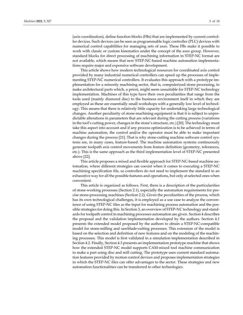
This article shows how modern technological resources for coordinated axis control
provided by many industrial numerical controllers can speed up the processes of imple‐
menting STEP‐NC numerical controllers. It evaluates this approach with a prototype im‐
plementation for a minority machining sector, that is, computerized stone processing, to
make architectural parts which, a priori, might seem unsuitable for STEP‐NC technology
implementation. Machines of this type have their own peculiarities that range from the
tools used (mainly diamond disc) to the business environment itself in which they are
employed as these are essentially small workshops with a generally low level of technol‐
ogy. This means that there is relatively little capacity for undertaking large technological
changes. Another peculiarity of stone‐machining equipment is that it is subject to unpre‐
dictable alterations in parameters that are relevant during the cutting process (variations
in the tool’s cutting power, changes in the stone’s structure, etc.) [20]. The technology must
take this aspect into account and if any process optimization is to be achieved in terms of
machine automation, the control and/or the operator must be able to make important
changes during the process [21]. That is why stone‐cutting machine software control sys‐
tems are, in many cases, feature‐based. The machine automation systems continuously
generate toolpath axis control movements from feature definition (geometry, tolerances,
etc.). This is the same approach as the third implementation level of STEP‐NC presented
above [22].
This article proposes a mixed and flexible approach for STEP‐NC‐based machine au‐
tomation, where different strategies can coexist when it comes to executing a STEP‐NC
machining specification file, so controllers do not need to implement the standard in an
exhaustive way for all the possible features and operations, but only at selected ones when
convenient.
This article is organized as follows. First, there is a description of the particularities
of stone‐working processes (Section 2.1), especially the automation requirements for pre‐
cise stone‐processing machines (Section 2.2). Given the peculiarities of the process, which
has its own technological challenges, it is employed as a use case to analyze the conven‐
ience of using STEP‐NC files as the input for machining process automation and the pos‐
sible strategies for doing this. In Section 3, an overview of STEP‐NC technology and stand‐
ards for toolpath control in machining processes automation are given. Section 4 describes
the proposal and the validation implementation developed by the authors. Section 4.1
presents the extended model proposed by the authors to obtain a STEP‐NC‐compatible
model for stone‐milling and sawblade‐cutting processes. This extension of the model is
based on the selection and definition of new features and on the modeling of the machin‐
ing processes. This model is first validated in a simulation implementation described in
Section 4.2. Finally, Section 4.3 presents an implementation prototype machine that shows
how the extended STEP‐NC model supports CAM‐mixed tool machine communication
to make a part using disc and mill cutting. The prototype uses current standard automa‐
tion features provided by motion control devices and proposes implementation strategies
in which the STEP‐NC files can offer advantages to the sector. These strategies and new
automation functionalities can be transferred to other technologies.

Machines 2021, 9, 327 4 of 18
2. Automation in the Stone‐Processing Sector
2.1. Stone‐Processing Equipment
Stone processing is a complex task that is influenced by several inter‐related factors.
Those factors have a direct influence on the quality of the final part and the efficiency of
the process. Examples include cooling efficiency during stone cutting, the physical–chem‐
ical properties of the stone, and the specific tools used on the stone.
There are several machines for cutting stone, using distinct technologies (diamond
wire cutting, sawblade cutting, milling, etc.) and different capacities (stone slicer, preci‐
sion saw for custom shapes, etc.) [23]. Figure 1 shows a classical sequence of processes
and machines used to obtain a final construction part. The stone typically comes from
quarries in big blocks that are processed by large machines with one or several tools (dia‐
mond wire, large‐diameter circular saws, blades, etc.). First (“Primary saw” in Figure 1),
a block‐cutter machine saws the rough block into, on the one hand, intermediate blocks to
make a secondary saw, and on the other hand, slabs to directly apply a surface finish (for
instance, polish). The next step (“Secondary saw” in Figure 1) is the generation of dimen‐
sional ashlars, usually done by large machines. Next, different multi‐axis precise ma‐
chines can be used depending on the type of the final part to be made (“Precise saw” in
Figure 1).
Figure 1. Stone‐cutting process.
Furthermore, the same part could be fashioned by different machines. For example,
a planar‐bounded shape could be created using a water jet or a circular saw. Different
machines can also be used to carry out different types of operations for a part. For exam‐
ple, the same part may need some work from a sawblade disc cutter tool to create a mold‐
ing, while a pocket would require a milling operation. Finally, a good surface finish can
be obtained by applying surface treatments, such as polish or a flamer.
For stone parts, such as moldings (Figure 2a) and columns (Figure 2b), which will be
used in construction, disc saws are the most popular device [21,24]. Stone‐cutting ma‐
chines with circular saws can therefore be highly complex, sometimes having several axes
(like the machine in Figure 3), so they can machine such complex parts. Figure 2 also high‐
lights the main geometric parameters of the features involved (for instance, the molding
profile line to be extruded along a linear path in Figure 2a).
Figure 3 shows a typical configuration of a stone‐cutting machine with three axes of
movement in the structure (X, Y, Z) and two additional axes for complex operations: one
axis is in the table to allow the rotation of the stone part (R) and another in the tool support
(M) to perform oblique cuts, where the different cutting tools are mounted. Moreover,
discs have limitations when it comes to making other features, such as pocket corners
(Figure 2c). For that kind of feature, stone milling is the most suitable option. There are
currently mixed‐technology stone machines that can carry out these complex operations.
They are suitable for plane cutting and turning, although they work with the same tool,
which is made of diamond. There are also mixed‐tool machines, such as the one in Figure
3, with a milling tool mounted on the disc axis, which can also be used to create features
(for instance, Figure 2d,e) using both technologies without having to switch machines.

Machines 2021, 9, 327 5 of 18
(a) (b) (c)
(d) (e)
Figure 2. Examples of stone parts with features: (a) surface cutting, (b) turning cutting, (c) milling, (d) surface cutting and
milling, and (e) disc cutting and milling.
Figure 3. Multipurpose stone‐cutting machine (surface cutting and mixed technology with cutting and milling).
Mixed tools can be a good choice for improving stone‐processing machine produc‐
tion when making architectural surface forms, as long as CAM‐CNC communication
based on features information provides information to the CNC control to make machin‐
ing more intelligent, with functionalities, such as online toolpath adaptation (sometimes
needed in stone processing, as detailed below).
2.2. Automation Requirements for Stone‐Processing Machines
A fundamental element in stone processing is the tool used for cutting. The use of a
disc limits to two the number of axes that can be interpolated with the sawblade inside
the stone, because the disc cannot turn on another plane other than the one for cutting.
However, to make complex features, it may be necessary to position more axes, which
means that these movements are made with the sawblade outside the stone, with ma‐
chines sometimes having five or more axes (Figure 3). Specific strategies are implemented
for moving the disc into the stone to cut and for moving it out to perform disc‐orientation
changes.
Cutting and milling become more difficult if the hardness increases in one part of the
stone or if the disc loses cutting efficiency. The machine may automatically detect the new

Machines 2021, 9, 327 6 of 18
operating conditions by means of several variables (the current of the motor, measure‐
ments from the encoders of current advance speed, etc.). To overcome cutting difficulties,
the disc speed must be changed (an easy operation), but the toolpath must also be recal‐
culated (for example, with a narrower distance between cuts). This will only be possible
if the toolpath‐generating subsystem has the information during execution that allows it
to undertake recalculations and the capacity to use that information to adapt and correct
itself while the process is underway. Because of the complexity of the surfaces generated
and the path planning, G‐code is created offline so it is generated efficiently [11]. Thus,
CNC machines become machines that do not take into account the geometry of the part
being manufactured, limiting themselves to executing one line after another [13]. This hin‐
ders the intelligence of the manufacturing process, as it does not allow the possibility of
correcting problems during machining, it does not close a data feedback flow, and it does
not take into account the traceability of real movement or changing situations during the
process [25]. To be able to perform this more intelligent automation, controllers need more
information from the CAM to make control decisions on their own.
3. New Standards for Machining Processes Automation: Work Specification and
Toolpath Control
In CAM‐CNC systems, the CAM communicates the machining operations to the
CNC controller to make a part. Section 3.1 presents the principles of STEP‐NC as a stand‐
ard specification for that. On the controller side, the work specification is translated into
axes commands to perform the required toolpath movements. Standard software re‐
sources to perform this control that are available in commercial motion controllers are
presented in Section 3.2.
3.1. STEP‐NC: Feature‐Based Machining Specifications
Since it began in 1999, STEP‐NC has been developed to provide a data model for a
new generation of intelligent CNC controllers. In 2007, it became an international stand‐
ard. STEP‐NC comprises two versions: ISO 14649 [26] and ISO 10303‐238 [27]. The former
defines the requirements for the detailed machining information in ARM (application ref‐
erence model) format, and the latter expresses the ARM data but in the form of generic,
integrated, defined STEP resources (geometry, topology, and tolerances) in the AIM for‐
mat (application interpreted model), enabling communication with other STEP models.
Both models (ARM and AIM) are defined in EXPRESS language with representation in a
physical ISO 10303‐21 format file.
ISO 14649 contains the definition of the detailed information requirements that must
be met for standardized CNC programming. This standard has several parts. Part 1 gives
an introduction and overview of a data model for working with CNC machines. Part 10
specifies the process data that are generally needed for CNC machining and which, there‐
fore, are common to several machining technologies. For each machining technology, one
standard is defined for the process data and another for the specific tools for that technol‐
ogy. Part 11 deals with milling data and part 111 with milling machine tools. Likewise,
Parts 12 and 112 deal with machine turning.
To cover more manufacturing technologies, new extensions to the STEP‐NC data
model are defined for other technologies, such as Part 13 for wire‐EDM, Part 14 for sink‐
EDM, Parts 15 and 16, which define wood and glass processing and the process of touch
probing inspection, respectively [28], and the recently included 3D‐printing data model
in Part 17. On other occasions, the extension or technological adaptation is limited to
working with the already existing features, but using new tools, new materials, or work‐
ing in new manufacturing environments, such as the footwear industry [29].
Stone processing has not yet been considered in the STEP‐NC standard. Regarding
stone milling, although this could be considered as an adaptation of the milling technol‐
ogy implementation that is already defined for metal, the inclusion of the new sawblade

Machines 2021, 9, 327 7 of 18
tool involves the need for new features and new associated technological parameters. Fea‐
tures are the core element in the CAD‐CAM‐CNC digital STEP chain of classical metal
processes [30]. Features are also the link between STEP and other engineering environ‐
ments, such as the building information model (BIM). BIM systems address digital for‐
malization and standardization of construction resources during the whole life cycle of
architectural resources (geometry, materials, structures, hierarchy among elements, etc.)
The BIM defines data models, including distinct constructive components, as features [31].
Therefore, a direct digital chain can be established from BIM‐CAM‐CNC through the
“standard” architectural features [32–34]. Section 4.1 details the extension of the STEP‐NC
model for stone processing proposed by the authors of this article.
3.2. Industrial Automation Standards for Motion Control and Resources for Interpolated
Toolpath Automation in Industrial Numerical Controllers
Given the particularity of stone‐processing technology in terms of the heterogeneity
of the raw material and the advantages offered by path recalculation halfway through the
process, some stone‐processing machine manufacturers developed specific control sys‐
tems that allow this.
Toolpath regeneration can be done segment by segment; that is, if the complete tool‐
path is made up of a set of segments, generation is done independently for each one and
the final path is the merging of those segments. The development technology supplied by
current controllers provides a set of resources that facilitate implementation of such solu‐
tions. However, it tends to require a major development effort to achieve the final auto‐
mation application.
To simplify development, specification 4 for motion control in PLCopen defines the
existence of a data structure, MC_PathRef, and two reusable function blocks:
MC_PathSelect to prepare all the data according to a trajectory and generate the position‐
ing profiles and MC_MovePath. With this solution, the paths to run can be specified and,
once that is done, control returned to the application. This solution is most advantageous
for an implementation that carries out a process that is not subject to changes; however, it
does not permit online adaptation. Distinct manufacturers implement the MC_MovePath
philosophy with models that are similar to the one given in the PLCopen standard. These
can be seen in Table 1, which specifies the ones that can work with the G‐code standard
and with user‐defined paths.
Table 1. Current motion resources provided by PLC manufacturers.
Manufac‐
turer Implementation
G‐
Code
UD 1
Path
Data
Preparation
Runtime
Adaptation Additional Information
Siemens
[35] MC_MovePath Yes Yes
Propietary external tool
(G‐code) MC_PathSelect
(user path)
Tool and radius
offset
Feedback of the remaining distance to the next toolpath and
current running trajectory. Insertion of actions, waits, and
planned events during trajectory execution.
Beckhoff
[36] MC_MovePath No Yes
MC_MoveLinear (circu‐
lar) AbsPreparation for
each toolpath
No
Insertion of planned intermediate jobs during the execution
of the trajectory. “Done” signal at the end of the specified set
of paths.
Lenze SE
[37] MC_MovePath Yes No
MC_PathRef
(FromFile) No
Current running line and its number if previously specified
in the G‐code by the “N” code.
ISG Indus‐
trielle
Steuer‐
ungstech‐
nik [38]
MC_MovePath Yes No MCV_GrpPathPrepare No
Insertion of planned intermediate jobs during the execution
of the trajectory. Feedback of the execution of the paths
through the block “MVC_ReadActualPathInfo”: current line
number, % distance completed, and deviation from the axis
position from the continuation position.
Yaskawa
[39] MC_MovePath Yes Yes
Read_Gcode_File
(G‐code) CP_PathGen‐
erator
(user path)
Tool offset
Remote path via UDP (minimum delay of 50 ms). Events and
jobs. Feedback of lines currently processed, executed, and the
difference between processed and executed total lines. It al‐
lows the movement of six axes and one extruder.
Rexygen
MC [40] MC_MovePath No Yes
Creation of the path by
using a drawing tool No
Single‐path oriented. Spatial trajectory generation using the
NURBS algorithm.
Machines 2021, 9, 327 8 of 18
Omron [41] MC_SyncMove‐
Absolute/Velocity No Yes
Generation of motion
profiles Yes
Cyclically using the specified target position or velocity for
the axis selected.
Beckhoff
[42] FIFO Axes No Yes
Generation of motion
profiles Yes
Synchronous motion of all axes specified in the FIFO table.
Main PLC task sends an array of points in each PLC cycle
specifying the synchronous FIFO time. Linear interpolation
between neighboring points in the FIFO task to obtain the ac‐
celeration and velocity values of the control loops of the mo‐
tion control task (SAF cycle). FIFO cycle can be faster than
NC cycle. 1 UD stands for user‐defined path.
In the MC_MovePath implementation in Table 1, on triggering the execution block
of the path, control over it is lost because this function block contains the planning of the
advanced movement that the controller carries out. In general, and in an easily imple‐
mentable way, it does not allow access to the setpoint to send to the servodrive, so it can
be modified online. In turn, it has the great advantage of easily implementing paths in
which, for example, no line adaptations are needed beyond tool offset, which is just like
most current machine tools. This can be seen in the column Runtime Adaptation in Table 1.
However, these limitations are overcome by the manufacturers Omron and Beckhoff,
among others, in different ways. Both use path programming from scratch as a basis, hav‐
ing to carry out the trajectory profile calculation and generate setpoints within the limits
imposed by speed, acceleration, and jerk, which is a highly demanding task for program‐
mers, although they do have less diffuse flexibility and adaptive control than earlier im‐
plementations.
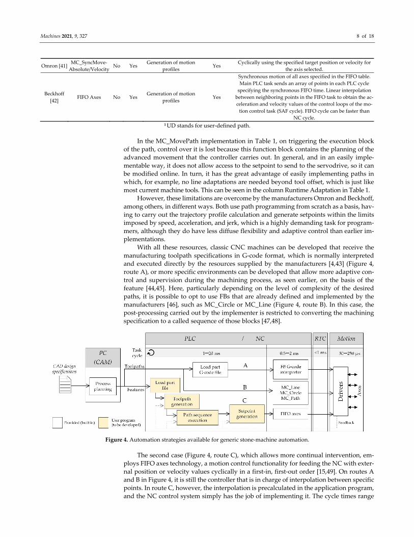
With all these resources, classic CNC machines can be developed that receive the
manufacturing toolpath specifications in G‐code format, which is normally interpreted
and executed directly by the resources supplied by the manufacturers [4,43] (Figure 4,
route A), or more specific environments can be developed that allow more adaptive con‐
trol and supervision during the machining process, as seen earlier, on the basis of the
feature [44,45]. Here, particularly depending on the level of complexity of the desired
paths, it is possible to opt to use FBs that are already defined and implemented by the
manufacturers [46], such as MC_Circle or MC_Line (Figure 4, route B). In this case, the
post‐processing carried out by the implementer is restricted to converting the machining
specification to a called sequence of those blocks [47,48].
Figure 4. Automation strategies available for generic stone‐machine automation.
The second case (Figure 4, route C), which allows more continual intervention, em‐
ploys FIFO axes technology, a motion control functionality for feeding the NC with exter‐
nal position or velocity values cyclically in a first‐in, first‐out order [15,49]. On routes A
and B in Figure 4, it is still the controller that is in charge of interpolation between specific
points. In route C, however, the interpolation is precalculated in the application program,
and the NC control system simply has the job of implementing it. The cycle times range
Machines 2021, 9, 327 9 of 18
from highly demanding values in the numerical control tasks, such as the FIFO axes case,
to less‐demanding values, such as typical cases of I/O management programs, automatic
cycles, and PLC logic. This final architecture, route C in Figure 4, is the one that was im‐
plemented in the prototype application, as described in Section 4.2.
Another common requirement for equipment like this is the need for simplicity in
use, given that it will typically provide service in the setting of a small‐ or medium‐sized
business. Furthermore, this tends to lead to simplification or limitation in terms of the type
of work undertaken with a limited set of features.
4. Feature‐Based Mixed‐Technology Automation Proposal for Stone‐Processing
Machines
This section describes a prototype STEP‐NC‐compliant implementation for stone‐
processing technology. A new extended STEP‐NC model was proposed by the authors to
include information on the new technology. Through this extended model (presented in
Section 4.1), information for stone‐cutting processes is communicated from a STEP‐NC
CAM system to a compliant STEP‐NC controller. Sections 4.2 and 4.3 describe the basis of
the STEP‐NC‐compliant automation developed by the authors using standard motion
control resources available in industrial controllers, and having as input, designs that fol‐
low the extended model in Section 4.1.
4.1. STEP‐NC Model Extension for Stone Processing
As mentioned previously, one of the fundamental elements in stone processing is the
tool used for cutting. Sawblade‐cutting technology for stone parts has several specific pa‐
rameters with no clear equivalents in technologies, such as milling or turning. These pa‐
rameters must be considered as new technological entities to be included in a STEP‐NC
model, as mentioned previously.
Thus, the proposed model for representing the stone‐cutting process in STEP‐NC is
based on the ARM model defined in ISO 14649‐10 [50] and the machining operations, fea‐
tures, and tools comply with the parts for milling and turning.
Figure 5 shows a comparison between the ARM models for the milling and turning
technologies and the proposal for disc cutting. The work information is organized in a
general workplan, which in turn contains a sequence of workingsteps that depend on each
technology, “disc_cutting_workingstep”, in the proposed case. This also enables the pos‐
sibility of having mixed‐technology machines, responding to the type of workingstep to
be carried out. These workingsteps associate a specific operation with a feature on the part
to be machined, and each operation describes the strategies to be followed, the parameters
to be used, and what has to be done to carry out manufacture of the feature. Below are the
details of the features and operations defined in the proposed model.
The features describe the areas for material elimination in a worked part and the de‐
sired end result of a machining process. Thus, the features inform the controller of “what”
is going to be done, so it can decide “how” to do it. The basic feature in the basic model
for stone cutting with a sawblade is the “cut‐out”, which can be described with the “slot”
feature already defined in ISO 14649‐10 [50], ISO 10303 AP‐224 [51], and as “cut_in” in the
specific turning standard, with the particularity of allowing cuts to be made with different
angles.

Machines 2021, 9, 327 10 of 18
Figure 5. Proposed STEP‐NC model for stone‐cutting tasks and their equivalents with the milling and turning models.
Two types of complex features are considered: planar features (“molding”, Figure 5)
for moldings, such as the ones in Figure 2a,d, and turning features (“turning_feature”,
Figure 5) for columns, spheres, and revolution parts (Figure 2b). Furthermore, the model
includes “replication_features”, which are repetition patterns of previous features.
As mentioned previously, the features are related to a specific operation or set of
operations and for a specific manufacturing technology. To understand the operations, it
is best to describe the process. The cutting process basically comprises three stages (cut‐
ting, removal of slides, and finish). For the first operation, cutting is carried out by means
of progressive cuts at a specified depth following the outline or profile of the final part. A
specified distance is left between these cuts (forming slices). The sawblade makes a com‐
plete longitudinal cut and descends step by step, making several parallel cuts at different
depths (passes). Once the desired depth is reached, the saw disc comes out of the stone
and moves to initiate another parallel cut at a specific distance from the previous one. The
second stage, removal of slides, requires manual intervention, typically by using chisels,
mallets, and other tools for working with stone. Finally, after removing the slides, the
definitive surface is obtained in the third stage, when the rough terraced profile resulting

Machines 2021, 9, 327 11 of 18
from stage two is smoothed with overlapping cuts. These operations are represented by
the “sawblade_machining_operation” label in Figure 5, and they can be of the new type
(surface operation), involving cutting, finishing, or slotting operations, or a legacy type
from turning technologies.
The sawblade‐cutting process is associated with different strategies for carrying out
each operation (“sawblade_machining_strategy” in Figure 5), from which it also inherits
those that exist for the case of turning with the particularity that they are done on a stone
machine with a saw disc tool. In the specific strategies for the stone‐cutting process, cuts
can be made with the disc totally parallel to the part (used for creating a molding, for
example) or perpendicular to the part (for example, in the initial slices of the stone). An‐
other specific cutting strategy to make slots comply with the direction to carry out the
cuts: unidirectional (material is only removed in one direction, lifting the disc, going back,
and resuming) or bidirectional (material is removed in both directions).
Figure 6 illustrates a detailed AIM‐format model of the cutting strategies to perform
a sawblade cut and the representation of the corresponding exchange file in a STEP‐NC
Part 21 program (Figure 6a). Figure 6b shows a schematic depiction of the complete bidi‐
rectional strategy process on a molding surface.
(a)
(b)
Figure 6. Complete bidirectional strategy for machining. (a) EXPRESS‐G representation of the cutting strategies in AIM
format and example of a program (STEP‐NC Part 21) with a bidirectional cutting strategy. (b) Graphical representation of
how a feature is carried out with a bidirectional cutting strategy on a molding surface.

Machines 2021, 9, 327 12 of 18
Finally, the disc saw machining operation also includes parameters associated with
the technology itself (feedrate value, sawblade speed value, override enabling variables,
etc.), and the parameters of the tool to be used (for example, sawblade diameter, maxi‐
mum allowed blade depth in the stone, etc.).
4.2. STEP‐NC Prototype for Stone‐Processing Automation: Simulation Implementation
To validate the model described earlier, a simulated STEP‐NC CC2 system imple‐
mentation was developed. This system takes a STEP‐NC AP238 file that includes the ge‐
ometry and toolpaths associated with specific features, although this feature information
is at a parametric level and has no associated geometry.
A screenshot of the developed simulation tool is given in Figure 7, in which the saw‐
blade tool executes the paths of a cutting workingstep. Figure 8 also shows a detail of the
setpoints sent to the simulator in a similar way to how they would be sent to a controller
order in a FIFO axes automation architecture.
Figure 7. Screenshot of the program developed for stone‐cutting simulation. Detail of the toolpath with setpoints.

Machines 2021, 9, 327 13 of 18
Figure 8. Express‐G structure of the elements to be moved. Polyline and composite curve computational implementation.
To generate these setpoints, the workingstep data structure is resorted to, and the
type of bounded curve it describes is identified. Figure 8 shows an example of the imple‐
mentations carried out and the algorithm that generates the corresponding setpoints (Al‐
gorithm 1):
Algorithm 1: Setpoint generation
Input: A list of segments of a bounded_curve (Sbc) and CNC deviation data (CNCdv)
Output: A list of points to use in a FIFO axes control (Lout)
First vertex point, Fv;
Last vertex point, Lv;
Spatial norm, Sn;
Uniform abscissa distribution of points on the bounded_curve, Up;
Projected point, Pp;
1 foreach segment in Sbc do 2 Fv, Lv ← Take the first vertex point and the last vertex point of the current segment 3 Sn ← Calculus of the spatial norm from both vertex points (Fv, Lv)
4 Up ← Computes a uniform abscissa distribution of points from Sn
5 foreach point in Up do
6 Update point with CNCdv
7 Pp ← Project the point and its parameter on the current segment of the
bounded_curve
8 Add Pp to Lout
9 end foreach
10 end foreach

Machines 2021, 9, 327 14 of 18
4.3. STEP‐NC Prototype for Stone‐Processing Automation: Industrial Controller
Implementation
A prototype implementation was built for a real stone‐processing machine with two
tool technologies: disc cutting and milling. An embedded CAD‐CAM system was devel‐
oped to select the parameters for the features, translated to XML (Extensible Markup Lan‐
guage), and communicated to the HMI (human machine interface). Both the CAD‐CAM
and the HMI ran on the same built‐in PC. The resulting file was the input for the low‐level
control module for the axis, alarm management, and input and output management. This
controller was a TwinCAT PLC RunTime system with TwinCAT‐NC axis control, pro‐
grammed in IEC 61131‐3 [52]. The prototype undertook online path calculation for a lim‐
ited number of features. Control algorithms were implemented ad hoc for each feature.
The algorithms generated the sections of toolpath during machining. Some features, such
as the sawblade cut, had the capacity for dynamic path recalculation. This path was
loaded into a FIFO axes and the NC task executed it, which is shown as “Fast task” in
Figure 9.
This prototype implementation was updated to support STEP‐NC part files as inputs.
Figure 9 gives a schematic diagram of the automation of a part to be made with sawblade
and milling technology. The corresponding input STEP‐NC file specified workingsteps
with operations and features for milling and stone cutting. Implementation using post‐
processing to G‐code would doubtless be the simplest, given that manufacturer‐supplied
resources for direct interpretation can be used for that format. This was used to carry out
the milling operations, which in this prototype, did not require online adaptation or the
development of an extension to the model (route A in Figure 9).
The move from a STEP‐NC CC1 format (with toolpath specifications) to a direct in‐
terpretation with FIFO axes architecture was also implemented, which is shown in route
B in Figure 9.
Figure 9. Automation strategies available for producing STEP‐NC‐compliant stone‐cutting machines.
The same algorithms used in the simulation for setpoint generation were those used
to feed the FIFO axes structures, although the use of specific FBs to carry out linear and
circular paths would also be valid. Route C in Figure 9 shows the move of the specification
of a STEP‐NC feature to the proprietary control of the already automated machine.
5. Discussion
The prototype implementation demonstrated how modern technological resources
for axis control provided by many industrial numerical controllers allow mixed‐technol‐
ogy implementation: ISO 6983 with STEP‐NC. Current general‐purpose numerical control

Machines 2021, 9, 327 15 of 18
devices provide function blocks that, in a direct way, have G‐code files as input for the
generation of positioning commands for a machine’s axes. The automation developer
simply has to parametrize the way in which those function blocks are executed. But cur‐
rent industrial controllers do not provide an equivalent function block for which the input
was a Part 21 STEP‐NC file containing explicit specification of the toolpath (CC1). How‐
ever, there is little advantage in having the toolpath specified in STEP‐NC instead of in G‐
code, which means that working with STEP‐NC CC1 also did not appear to provide any
significant advantage, and there is the disadvantage of having to implement it on purpose.
The prototype implementation analyzed from the controller side, the automation
procedures and technology to implement STEP‐NC feature specifications. Two cases were
addressed: the case of features defined by the current edition of the standard (for instance,
milling features) and the case of new features and associated technological parameters not
defined in the current state of the STEP‐NC standard (for instance, disc‐cutting features).
Neither of them is supported for current commercial controllers, so both have to be devel‐
oped deliberately for a specific new machine.
6. Conclusions
From the point of view of process automation, it would only be advantageous to use
an automation that directly processed features from STEP‐NC files to the extent that the
numerical controllers implemented specific FBs for each feature in a specific machining
technology, as reported in [47,48,53]. Nevertheless, for other features that are not imple‐
mented by the manufacturers or for which a specific strategy would be necessary, ad hoc
implementation of all the software would once again have to be resorted to for its auto‐
mation. In both cases however, the advantage gained from using STEP‐NC is the fact of
having a digital way from CAD‐CAM. That is not yet the case in minority technologies,
such as stone processing, in which many operations are still done by hand. It is then
doubtful whether the convenience of a STEP‐NC implementation, either from scratch or
mixed, is suitable for this scenario. It may be justifiable to consider it depending on how
many environments, such as the BIM, which are highly structured, and new commercial
CNC systems incorporate direct processing of architectural features in STEP‐NC format.
The true potential of STEP‐NC from a machine automation point of view is that re‐
leased features information (including shape and tolerances) drives the work. If that is not
the case, there are no significant advantages compared to using G‐code. In fact, for the
cases in which STEP‐NC implementation is based exclusively on toolpath specification,
the vast majority of machine control implementations with STEP‐NC as input use G‐code
post‐processing. Working with features, however, presents various challenges. One of
them concerns their complexity. Another is the fact that all the features or the associated
technologies (new tool, a new way of executing the job) needed for a specific type of ma‐
chine or process may not be defined, as is the case, for instance, in minority sectors, such
as stone‐processing equipment or the development of specific machinery.
As for the complexity of work with STEP‐NC formats with feature specification, the
degree to which new control devices (axis controllers) have factory‐fitted function blocks
(algorithms) devoted to each defined feature will facilitate their implementation. If a spe‐
cific feature is not defined, or the FB implementation that deals with it does not corre‐
spond to the required technology (tool or process), the possibility of mixing, in the same
controller and in the same job execution (of a part), different forms of implementation
would allow progressive and incremental transition to more intense levels of STEP‐NC
implementation, as proven in the prototype implementation. That is, not having to choose
between an implementation that is 100% STEP‐NC or 0% STEP‐NC, but rather implement‐
ing, in a simple way, intermediate alternatives: one feature with G‐code post‐processing,
another with implementation using a specific FB provided by the control device manufac‐
turer, and another using an FB developed by the machine manufacturer, etc. In this case,
where implementation does not require extra effort, it could be possible to consider the

Machines 2021, 9, 327 16 of 18
use of STEP‐NC technology for new stone equipment or minority technologies or pro‐
cesses with similar conditions. However, the problem comes back to the effort that must
be made to carry out a direct implementation from scratch, particularly for a setting such
as working with stone.
Having a choice of several automation resources depending on feature types in a part
STEP‐NC file could be a driving factor for incremental STEP‐NC technology adoption at
the machine control level, because in this way, controllers do not need to implement the
standard in an exhaustive fashion for all the possible features and operations, but only at
selected ones when convenient.
Author Contributions: Conceptualization, J.G.; methodology, J.G. and J.S.; software, J.G. and D.S.;
validation, J.G.; formal analysis, J.G. and D.S.; investigation, J.G. and D.S.; resources, J.S.; data cura‐
tion, J.G. and J.S.; writing—original draft preparation, J.G. and D.S.; writing—review and editing,
J.G. and D.S.; visualization, J.G. and J.S. All authors have read and agreed to the published version
of the manuscript.
Funding: This research received no external funding.
Institutional Review Board Statement: Not applicable.
Informed Consent Statement: Not applicable.
Data Availability Statement: Not applicable.
Conflicts of Interest: The authors declare no conflict of interest.
References
1. ISO 6983‐1:2009 Automation Systems and Integration—Numerical Control of Machines—Program Format and Definitions of Address
Words—Part 1: Data Format for Positioning, Line Motion and Contouring Control Systems; ISO: Geneva, Switzerland, 2009.
2. Gardan, J.; Makke, A.; Recho, N. A Method to Improve the Fracture Toughness Using 3D Printing by Extrusion Deposition.
Procedia Struct. Integr. 2016, 2, 144–151. https://doi.org/10.1016/j.prostr.2016.06.019.
3. Megalingam, R.K.; Raagul, S.; Avs, Y.; Sriniketh, K.; Bcsc, S. Compact, Handheld Dosa Bot Design. In Proceedings of the 2018
2nd International Conference on Trends in Electronics and Informatics (ICOEI), Tirunelveli, India, 11–12 May 2018; pp. 147–
151.
4. Ivan, M.; Ernek, M.; Miklovicova, E. TwinCAT Control of CNC Machine over CoE. In Proceedings of the 2019 22nd International
Conference on Process Control (PC19), Strbske Pleso, Slovakia, 11–14 June 2019; pp. 91–96.
5. S SIMOTION G‐Code Interpreter—ID: 109477030—Industry Support Siemens. Available online: https://support.industry.sie‐
mens.com/cs/document/109477030/simotion‐g‐code‐interpreter?dti=0&pnid=14515&lc=en‐US (accessed on 23 October 2021).
6. Lu, X.; Zhou, Y.F.; Xing, X.L.; Shao, L.Y.; Yang, Q.X.; Gao, S.Y. Open‐Source Wire and Arc Additive Manufacturing System:
Formability, Microstructures, and Mechanical Properties. Int. J. Adv. Manuf. Technol. 2017, 93, 2145–2154.
https://doi.org/10.1007/s00170‐017‐0636‐z.
7. Wang, M.; Zhang, H.; Hu, Q.; Liu, D.; Lammer, H. Research and Implementation of a Non‐Supporting 3D Printing Method
Based on 5‐Axis Dynamic Slice Algorithm. Robot. Comput.‐Integr. Manuf. 2019, 57, 496–505.
https://doi.org/10.1016/j.rcim.2019.01.007.
8. Xu, X.W.; Newman, S.T. Making CNC Machine Tools More Open, Interoperable and Intelligent—A Review of the Technologies.
Comput. Ind. 2006, 57, 141–152. https://doi.org/10.1016/j.compind.2005.06.002.
9. Xu, X.W. Realization of STEP‐NC Enabled Machining. Robot. Comput.‐Integr. Manuf. 2006, 22, 144–153.
https://doi.org/10.1016/j.rcim.2005.02.009.
10. Lu, Y.; Xu, X.; Wang, L. Smart Manufacturing Process and System Automation—A Critical Review of the Standards and Envi‐
sioned Scenarios. J. Manuf. Syst. 2020, 56, 312–325. https://doi.org/10.1016/j.jmsy.2020.06.010.
11. Hardwick, M.; Zhao, Y.F.; Proctor, F.M.; Nassehi, A.; Xu, X.; Venkatesh, S.; Odendahl, D.; Xu, L.; Hedlind, M.; Lundgren, M.; et
al. A Roadmap for STEP‐NC‐Enabled Interoperable Manufacturing. Int. J. Adv. Manuf. Technol. 2013, 68, 1023–1037.
https://doi.org/10.1007/s00170‐013‐4894‐0.
12. Rauch, M.; Laguionie, R.; Hascoet, J.‐Y.; Suh, S.‐H. An Advanced STEP‐NC Controller for Intelligent Machining Processes. Ro‐
bot. Comput.‐Integr. Manuf. 2012, 28, 375–384. https://doi.org/10.1016/j.rcim.2011.11.00.
13. Rauch, M.; Laguionie, R.; Hascoet, J.‐Y. Achieving a STEP‐NC Enabled Advanced NC Programming Environment. In Advanced
Design and Manufacturing Based on STEP; Xu, X., Nee, A.Y.C., Eds.; Springer Series in Advanced Manufacturing; Springer: Lon‐
don, UK, 2009; pp. 197–214, ISBN 978‐1‐84882‐738‐7.
14. Lan, H.; Liu, R.; Zhang, C. A Multi‐Agent‐Based Intelligent STEP‐NC Controller for CNC Machine Tools. Int. J. Prod. Res. 2008,
46, 3887–3907. https://doi.org/10.1080/00207540701213494.

Machines 2021, 9, 327 17 of 18
15. Xiao, W.; Zheng, L.; Huan, J.; Lei, P. A Complete CAD/CAM/CNC Solution for STEP‐Compliant Manufacturing. Robot. Comput.‐
Integr. Manuf. 2015, 31, 1–10. https://doi.org/10.1016/j.rcim.2014.06.003.
16. Latif, K.; Adam, A.; Yusof, Y.; Kadir, A.Z.A. A Review of G Code, STEP, STEP‐NC, and Open Architecture Control Technologies
Based Embedded CNC Systems. Int. J. Adv. Manuf. Technol. 2021, 114, 2549–2566. https://doi.org/10.1007/s00170‐021‐06741‐z.
17. Slavkovic, N.; Zivanovic, S.; Milutinovic, D. An Indirect Method of Industrial Robot Programming for Machining Tasks Based
on STEP‐NC. Int. J. Comput. Integr. Manuf. 2019, 32, 43–57. https://doi.org/10.1080/0951192X.2018.1543952.
18. Alvares, A.J.; Rodriguez, E.; Riano Jaimes, C.I.; Toquica, J.S.; Ferreira, J.C.E. STEP‐NC Architectures for Industrial Robotic Ma‐
chining: Review, Implementation and Validation. IEEE Access 2020, 8, 152592–152610. https://doi.org/10.1109/AC‐
CESS.2020.3017561.
19. PLCopen. Creating Reusable, Hardware Independent Motion Control Applications via IEC 61131‐3 and PLCopen Function Blocks; PLCo‐
pen: Zaltbommel, The Netherlands, 2018.
20. Wang, C.Y.; Clausen, R. Computer Simulation of Stone Frame Sawing Process Using Diamond Blades. Int. J. Mach. Tools Manuf.
2003, 43, 559–572. https://doi.org/10.1016/S0890‐6955(03)00019‐1.
21. Tönshoff, H.K.; Hillmann‐Apmann, H.; Asche, J. Diamond Tools in Stone and Civil Engineering Industry: Cutting Principles,
Wear and Applications. Diam. Relat. Mater. 2002, 11, 736–741. https://doi.org/10.1016/S0925‐9635(01)00561‐1.
22. Zhang, C.; Liu, R.; Hu, T. On the Futuristic Machine Control in a STEP‐Compliant Manufacturing Scenario. Int. J. Comput. Integr.
Manuf. 2006, 19, 508–515. https://doi.org/10.1080/09511920600623682.
23. Brook, B. Principles of Diamond Tool Technology for Sawing Rock. Int. J. Rock Mech. Min. Sci. 2002, 39, 41–58.
https://doi.org/10.1016/S1365‐1609(02)00007‐2.
24. Mikaeil, R.; Mokhtarian, M.; Shaffiee Haghshenas, S.; Careddu, N.; Alipour, A. Assessing the System Vibration of Circular
Sawing Machine in Carbonate Rock Sawing Process Using Experimental Study and Machine Learning. Geotech. Geol. Eng. 2021,
, 1‐17. https://doi.org/10.1007/s10706‐021‐01889‐7.
25. Danjou, C.; Le Duigou, J.; Eynard, B. Closed‐Loop Manufacturing Process Based on STEP‐NC. Int. J. Interact. Des. Manuf. 2017,
11, 233–245. https://doi.org/10.1007/s12008‐015‐0268‐1.
26. ISO 14649:2003 Industrial Automation Systems and Integration—Physical Device Control—Data Model for Computerized Numerical
Controllers; ISO: Geneva, Switzerland, 2003.
27. ISO 10303‐238:2020 Industrial Automation Systems and Integration—Product Data Representation and Exchange—Part 238: Applica‐
tion Protocol: Model Based Integrated Manufacturing; ISO: Geneva, Switzerland, 2020.
28. Kumar, S.; Newman, S.T.; Nassehi, A.; Vichare, P.; Tiwari, M.K. An Information Model for Process Control on Machine Tools.
In Advances in Intelligent and Soft Computing, Proceedings of the 6th CIRP‐Sponsored International Conference on Digital Enterprise
Technology; Huang, G.Q., Mak, K.L., Maropoulos, P.G., Eds.; Springer: Berlin/Heidelberg, Germany, 2010; Volume 66, pp. 1565–
1582, ISBN 978‐3‐642‐10429‐9.
29. Gómez‐Hernández, J.‐F.; Davia‐Aracil, M.; Sanchez‐Romero, J.‐L.; Jimeno‐Morenilla, A. An Approach to Implement STEP‐NC
in the Footwear Industry. Comput. Ind. 2021, 125, 103384. https://doi.org/10.1016/j.compind.2020.103384.
30. Nassehi, A.; Newman, S.T.; Xu, X.W.; Rosso, R.S.U. Toward Interoperable CNC Manufacturing. Int. J. Comput. Integr. Manuf.
2008, 21, 222–230. https://doi.org/10.1080/09511920701607899.
31. Davtalab, O.; Kazemian, A.; Khoshnevis, B. Perspectives on a BIM‐Integrated Software Platform for Robotic Construction
through Contour Crafting. Autom. Constr. 2018, 89, 13–23. https://doi.org/10.1016/j.autcon.2018.01.006.
32. Correa, F. Robot‐Oriented Design for Production in the Context of Building Information Modeling. In Proceedings of the 33rd
International Symposium on Automation and Robotics in Construction and Mining, Auburn, AL, USA, 21 July 2016; pp. 853–
861.
33. Pellegrinelli, S.; Terkaj, W.; Urgo, M. A Concept for a Pallet Configuration Approach Using Zero‐Point Clamping Systems.
Procedia CIRP 2016, 41, 123–128. https://doi.org/10.1016/j.procir.2015.12.084.
34. Hamid, M.; Tolba, O.; El Antably, A. BIM Semantics for Digital Fabrication: A Knowledge‐Based Approach. Autom. Constr. 2018,
91, 62–82. https://doi.org/10.1016/j.autcon.2018.02.031.
35. Siemens AG. Library Kinematics Control; Siemens AG: Munich, Germany, 2021.
36. MC_MovePath—Beckhoff Automation GmbH & Co. KG. Available online: https://infosys.beckhoff.com/english.php?con‐
tent=../content/1033/tf5410_tc3_collision_avoidance/8893267467.html&id= (accessed on 23 October 2021).
37. LENZE. Motion Function Libraries; Reference manual PLC Designer; Lenze Automation GmbH: Stuttgart, Germany, 2019.
38. MC_MovePath—ISG Industrielle Steuerungstechnik GmbH. Available online: https://www.isg‐stuttgart.de/kernel‐html5/en‐
GB/190234507.html (accessed on 23 October 2021).
39. Yaskawa Electric Corporation. MotionWorks; Toolbox Introduction; Yaskawa Electric Corporation: Kitakyushu, Japan, 2017.
40. REX Controls. Function Blocks of REXYGEN; REX Controls s.r.o.: Pilsen, Czech Republic, 2021.
41. OMRON Corporation. NJ/NX‐Series Motion Control Instructions Reference Manual; OMRON Corporation: Kyoto, Japan, 2019; p.
768.
42. Beckhoff Automation GmbH & Co. KG. TwinCAT 3|NC FIFO AXES; Beckhoff Automation GmbH & Co. KG: Verl, Germany,
2021.
43. Liu, L.; Yao, Y.; Li, J. Development of a Novel Component‐Based Open CNC Software System. Int. J. Adv. Manuf. Technol. 2020,
108, 3547–3562. https://doi.org/10.1007/s00170‐020‐05590‐6.

Machines 2021, 9, 327 18 of 18
44. Zhang, X.; Nassehi, A.; Safaieh, M.; Newman, S.T. Process Comprehension for Shopfloor Manufacturing Knowledge Reuse. Int.
J. Prod. Res. 2013, 51, 7405–7419. https://doi.org/10.1080/00207543.2012.757669.
45. Sun, P.; Liu, Q.; Ding, J.; Pi, S. Open CNC System Design for Multiple Intelligent Functions Based on TwinCAT and NET Frame‐
work. In Proceedings of the 2017 IEEE International Conference on Mechatronics and Automation (ICMA), Takamatsu, Japan,
6–9 August 2017; pp. 910–915.
46. Wang, H.; Tang, X.; Song, B.; Wang, X. A Novel Architecture of the Embedded Computer Numerical Control System Based on
PLCopen Standard. Proc. Inst. Mech. Eng. B. J. Eng. Manuf. 2014, 228, 595–605. https://doi.org/10.1177/0954405413506197.
47. Wang, H.; Xu, X.; Tedford, J.D. An Adaptable CNC System Based on STEP‐NC and Function Blocks. Int. J. Prod. Res. 2007, 45,
3809–3829. https://doi.org/10.1080/00207540600774075.
48. Harbs, E.; Negri, G.H.; Jarentchuk, G.; Hasegawa, A.Y.; Rosso, R.S.U., Jr.; da Silva Hounsell, M.; Lafratta, F.H.; Ferreira, J.C.
CNC‐C2: An ISO14649 and IEC61499 Compliant Controller. Int. J. Comput. Integr. Manuf. 2021, 34, 621–640.
https://doi.org/10.1080/0951192X.2021.1911002.
49. Hu, P.; Han, Z.; Fu, Y.; Fu, H. Implementation of Real‐Time Machining Process Control Based on Fuzzy Logic in a New STEP‐
NC Compatible System. Math. Probl. Eng. 2016, 2016, 9814973. https://doi.org/10.1155/2016/9814973.
50. ISO 10303‐10:2004 Industrial Automation Systems and Integration—Physical Device Control—Data Model for Computerized Numerical
Controllers—Part 10: General Process Data; ISO: Geneva, Switzerland, 2004.
51. ISO 10303‐224:2006 Industrial Automation Systems and Integration—Product Data Representation and Exchange—Part 224: Applica‐
tion Protocol: Mechanical Product Definition for Process Planning Using Machining Features; ISO: Geneva, Switzerland, 2006.
52. IEC 61131‐3:2013 Programmable Controllers—Part 3: Programming Languages; IEC: Geneva, Switzerland, 2013.
53. Adamson, G.; Wang, L.; Moore, P. Feature‐Based Function Block Control Framework for Manufacturing Equipment in Cloud
Environments. Int. J. Prod. Res. 2019, 57, 3954–3974. https://doi.org/10.1080/00207543.2018.1542178.