Strength and Reliability of Ships ‘As-Built’
6
Copyright © 2012 by ASME 1 Proceedings of the 31th International Conference on Offshore Mechanics and Arctic Engineering OMAE2012 July 1-6, 2012, Rio de Janeiro, Brazil OMAE2012-83877 STRENGTH AND RELIABILITY OF SHIPS ‘AS-BUILT’ Kalman Žiha Boris Ljubenkov Nikola Dupor Janoš Kodvanj Ante Bakić University of Zagreb Faculty of Mechanical Engineering and Naval Architecture Department of Naval Architecture and Ocean Engineering Zagreb, Croatia ABSTRACT This report firstly presents the rule based scantlings and sectional properties of the example ship defined by using the nominal properties of mild shipbuilding steel. It also describes the way of collection of characteristic material specimens of rolled steel plates and bars delivered by the steel manufacturer to the shipyard for to the example ship. Secondly it summarizes the results of tensile testing in the Laboratory for experimental mechanics of the Faculty of Mechanical Engineering and Naval Architecture in Zagreb of plates and bars denoted here as ‘in-built’ material properties for the example ship according to the production plans. The report then reminds on the rule based material properties for acceptance purposes. Next it considers the influence of ‘in-built’ mechanical properties with respect to the rule requirements on local, global and ultimate strength of ships. The report discusses material properties other than yield strength, which participate in the assessment of the overall ship safety such as the weld strength, buckling and fatigue strength, low temperature behavior, corrosion and reliability. The results of the tensile testing of ‘in-built’ materials are then applied to checking of the local, global and ultimate ‘as- built’ strength of the example ship’s hull instead of the ‘as- designed’ strength defined by the nominal material properties. The report at the end discusses the differences between the ‘as-designed’ and the ‘as-built’ hull strength, fatigue life and reliability. It suggests minimization of the hull strength uncertainties by adopting the mechanical properties of ‘in- built’ materials. The conclusion supports the stirring idea of this report that in addition to the ‘as-designed’ strength, a ship deserves individualized assessment of the “as-built” ship hull strength based on the measured realistic ‘in-built’ properties. INTRODUCTION Most of the ship's principal characteristics are defined in the design phase. Some of these characteristics are modified, calculatedly, intentionally or erratically changed or observed as different in the completion, building, quality control and in trials or in operational phases. Some of the changes and modifications such as for example principle dimensions, load carrying capacity, stability and speed are sometimes checked and considered after the delivery as ‘as-built’ particulars but it is normally not the case with the ‘in-built’ material properties and ‘as-built’ hull strength and reliability of ship hull strength. Elastic and plastic material properties vitally influence the ship hull strength both locally and globally in static and dynamic conditions. The material properties are normally specified in the design phase and considered as such all through the design, construction, delivery, approval, manufacturing, building and operation phases. The ship’s hull strength is throughout its entire lifetime identified with the nominal material properties for acceptance purposes as they are declared by the manufacturer and required by the rules. The local and global longitudinal strength analysis of the hull structures, including the ultimate strength and fatigue life assessment, are normally part of the design phase and seldom are verified after the ship’s delivery. The preliminary structural design is based on rules for building and checked by direct calculations using design material properties equal to nominal in order to assure that the hull is strong enough. Testing of material properties is required in cases of particular strength problems on trials and in service. Recent testing, measurements, experiences and observations indicate how some material properties differ of applied design values and statistically deviate significantly of the nominal values.
-
Upload
independent -
Category
Documents
-
view
1 -
download
0
Transcript of Strength and Reliability of Ships ‘As-Built’

Copyright © 2012 by ASME 1
Proceedings of the 31th International Conference on Offshore Mechanics and Arctic Engineering OMAE2012
July 1-6, 2012, Rio de Janeiro, Brazil
OMAE2012-83877
STRENGTH AND RELIABILITY OF SHIPS ‘AS-BUILT’
Kalman Žiha Boris Ljubenkov Nikola Dupor Janoš Kodvanj Ante Bakić
University of Zagreb
Faculty of Mechanical Engineering and Naval Architecture Department of Naval Architecture and Ocean Engineering
Zagreb, Croatia
ABSTRACT This report firstly presents the rule based scantlings and sectional properties of the example ship defined by using the nominal properties of mild shipbuilding steel. It also describes the way of collection of characteristic material specimens of rolled steel plates and bars delivered by the steel manufacturer to the shipyard for to the example ship. Secondly it summarizes the results of tensile testing in the Laboratory for experimental mechanics of the Faculty of Mechanical Engineering and Naval Architecture in Zagreb of plates and bars denoted here as ‘in-built’ material properties for the example ship according to the production plans. The report then reminds on the rule based material properties for acceptance purposes. Next it considers the influence of ‘in-built’ mechanical properties with respect to the rule requirements on local, global and ultimate strength of ships. The report discusses material properties other than yield strength, which participate in the assessment of the overall ship safety such as the weld strength, buckling and fatigue strength, low temperature behavior, corrosion and reliability. The results of the tensile testing of ‘in-built’ materials are then applied to checking of the local, global and ultimate ‘as-built’ strength of the example ship’s hull instead of the ‘as-designed’ strength defined by the nominal material properties. The report at the end discusses the differences between the ‘as-designed’ and the ‘as-built’ hull strength, fatigue life and reliability. It suggests minimization of the hull strength uncertainties by adopting the mechanical properties of ‘in-built’ materials. The conclusion supports the stirring idea of this report that in addition to the ‘as-designed’ strength, a ship deserves individualized assessment of the “as-built” ship hull strength based on the measured realistic ‘in-built’ properties.
INTRODUCTION Most of the ship's principal characteristics are defined in the design phase. Some of these characteristics are modified, calculatedly, intentionally or erratically changed or observed as different in the completion, building, quality control and in trials or in operational phases. Some of the changes and modifications such as for example principle dimensions, load carrying capacity, stability and speed are sometimes checked and considered after the delivery as ‘as-built’ particulars but it is normally not the case with the ‘in-built’ material properties and ‘as-built’ hull strength and reliability of ship hull strength. Elastic and plastic material properties vitally influence the ship hull strength both locally and globally in static and dynamic conditions. The material properties are normally specified in the design phase and considered as such all through the design, construction, delivery, approval, manufacturing, building and operation phases. The ship’s hull strength is throughout its entire lifetime identified with the nominal material properties for acceptance purposes as they are declared by the manufacturer and required by the rules. The local and global longitudinal strength analysis of the hull structures, including the ultimate strength and fatigue life assessment, are normally part of the design phase and seldom are verified after the ship’s delivery. The preliminary structural design is based on rules for building and checked by direct calculations using design material properties equal to nominal in order to assure that the hull is strong enough. Testing of material properties is required in cases of particular strength problems on trials and in service. Recent testing, measurements, experiences and observations indicate how some material properties differ of applied design values and statistically deviate significantly of the nominal values.

Copyright © 2012 by ASME 2
APPLIED EXAMPLE The example presents a bulk-carrier (Fig. 1) designed and built in one of the Croatian shipyards under CSR for bulk-carriers [1] with following main particulars: Ship particulars (Bulk Carrier) 51900 tdw: Length overall Loa = 189.9 m Length between perpendiculars Lpp = 182.0 m Rule (construction) length L = 180.6 m Breadth molded B = 32.2 m Depth molded D = 17.1 m Design draught Td = 11.0 m Scantling draught T = 12.3 m Block coefficient Cb = 0.8322 Maximum service speed v = 15 kn The CSR class bulk carriers are often being built of either material grade AH32 (yield stress=315 MPa) or AH36/DH36 (yield stress=355 MPa). However, the example applies rather a single material type analysis in order to simplify the interpretation of the steering aim of this report, which is, how the measured material properties affect the local and global safety assessment made in the design phase regardless of the ship type. For this reason, the gross and net hull sectional properties were recalculated as if they were of a single MS grade A material type (Table 1). Otherwise, all material types have to be considered in the analysis of the ‘as-built’ strength.
Figure 1. Midship section of the example bulk carrier
MATERIAL SELECTION IN FABRICATION PHASE Material has been selected in the shipyard with the aim to get specimens from characteristic area of the ship hull which relevantly represents local and global safety requirements. The selected plate and bar are parts of the bilge tank which is located in cargo area of the example ship. The material for testing of mechanical properties was the MS grade A steel approved by Classification Society with nominal yield stress Ry=235 MPa according to the example ship design condition. The specimens of rolled plate were cut from the plate with dimensions 11600x2050x16 mm with the nesting plan (Fig. 2).
Figure 2. Plate with nesting plan providing test specimens
Figure 3. Flat bar providing test specimens
The specimens of rolled profiles were cut from a flat bar 250x15 mm whose cutting drawing is shown by Fig. 3. It is important to point out that specimens had to be cut with mechanical or water jet cutting because OXY-fuel cutting (oxyacetylene cutting) or plasma cutting causes changes of the material structure and mechanical properties of specimens. TENSILE TESTING OF THE SELECTED MATERIALS The standardized tensile testing are performed [3] (Fig. 4).
Figure 4. Standardized material specimens before testing
The testing plan in this report considered six specimens of plating (Fig. 2): three in longitudinal direction of rolling (Fig. 5) and three in transverse direction (Fig. 6) and six specimens of flat bars (Fig. 3): three in longitudinal direction (Fig. 7) of rolling and three in transverse direction (Fig. 8).
Figure 5. Tensile tests of plating: longitudinal specimens
Figure 6. Tensile tests of plating: transverse specimens
E (MPa) ReH & Rm (MPa) εm (%) εu (%) 225 336 461 20.71 37.21 209 343 467 19.63 34.42 208 330 462 20.01 35.21
E (MPa) ReH & Rm (MPa) εm (%) εu (%) 188 332 468 21.08 37.61 207 343 468 20.52 33.33 225 343 466 19.55 33.75
Strain %
Strain %
Plating-longitudinal direction of rolling
Plating-transverse direction of rolling
ReH
Rm εm
εu
Ry=235 εu
Rm εm
Stre
ss M
Pa
Stre
ss M
Pa
Rf
Rf Rf
Ry=235

Copyright © 2012 by ASME 3
Figure 7. Tensile tests of stiffeners: longitudinal specimen
Figure 8. Tensile tests of stiffeners: transverse specimens
THE RULE BASED DESIGN MATERIAL PROPERTIES When steels with a minimum guaranteed yield stress other than RY=235 MPa are used, hull scantlings are determined by taking into account the material factor k (Table 1) [1]. For intermediate values of yield stress ReH the material factor k may be obtained by interpolation as it is shown:
295/( 60)eHk R= + (1)
RULE BASED DESIGN STRENGTH OF THE SHIP The rule based strength analysis of ships admits that the structural responses should be within the elastic properties of the building materials. This implies allowable rule based working stresses R in all structural parts and in all loading conditions based on the nominal design material factor k (1). Design working stresses Rd in MPa should not exceed the allowable normal stress according to the next requirement [1]:
1, 190 /d ALL dR kσ= = (2)
The design safety factor fd for nominal properties of steels can be expressed using kd as in (1) in (2) (Table 1) as shown:
e e/ /190d Hd d d Hdf R R k R= = ⋅ (3a)
Table 1. Rule based design material factor k
ReHd MPa kd (1) Rd (2) 1/ kd dk fd (3a) 235 1 190 1 1 1.24 315 0.78 242 1.27 0.88 1.30 355 0.72 267 1.41 0.85 1.33 390 0.68 280 1.47 0.82 1.40
THE EFFECT OF ‘IN-BUILT’ MATERIAL PROPERTIES The minimal yield stresses ReHi=MIN(ReH) from all specimens (Figs. 5-8) define the ’in-built’ material factor ki (1) and allowable working stress Ri=190/ki as in (3) (Table 2).
The ‘as-built’ safety factor is then presented as follows: ( ) / / 190a eH i i eHif MIN R R k R= = ⋅ (3b)
The strength factor fs for plating and stiffening against elastic bending and in-plane loads (3a, 3b) [1] for the ‘in-built’ working stress Ri relative to design working stress Rd (Table 2, Fig. 10) where fi=ReHi/ReHd, is then defined as follows:
( / ) / /s i d a i d d if f f f R R k k= ⋅ = = (3c)
Table 2. Minimal yield strength of “in-built” materials* MIN(ReH) MPa f=ReHi/ReHd ki (1) Ri (2) fa(3b) fs(3c) sf
Plating 330 1.40 0.76 251 1.74 1.32 1.15 Stiffening 315 1.34 0.78 244 1.66 1.28 1.13
*Mean of all 11 tests is ReH=330, st. dev. σ=3.15, c.o.v.=0.01.
The testing indicated that the material properties of plating and stiffening are not necessarily identical (∼5%) (Table 2). ‘AS-BUILT’ LOCAL STRENGTH ASSESMENT The ‘as-built’ strength factor fs (3c) aptly assesses the local bending strength under lateral loads p of ‘in-built’ materials. Plating The general term for design plate thickness in mm under lateral loads p follows from the approximate plate theory and can be expressed by the material factor kd (1) as it is shown:
d p d Ct s c k p t= ⋅ ⋅ ⋅ + (4) In (4) cp includes edge supporting conditions and design
strength, s is the width of plating and tC is the corrosion additions in mm not depending on material properties [1]. The plating efficiency due to higher ‘in-built’ yield strength can be presented using factor fs (3c) (Table 2) by an equivalent equally stressed plate thickness as it follows:
/i d st t f= (4a) Stiffening The stiffener efficiency subjected to bending under lateral pressures p [1] due to higher ‘in-built’ yield strength can be presented using factor fs (3c) by equivalent section modulus in cm3 and section area in cm2 defined by the beam theory:
2 /i w sW c p s f= ⋅ ⋅ ⋅ (5a) /shi a sA c p s f= ⋅ ⋅ ⋅ (5b)
In (5a, b) cw and ca are the constants in proportion to the design strength and supporting conditions at stiffener ends, s is the width of supporting plating, is the unsupported length. Buckling strength The elastic buckling stress σE depends on Young’s modulus E not on the yield strength ReH. The critical plastic buckling stress σC follows the nonlinear Johnson-Ostenfeld’s correction for σE above 50% of the design yield stress ReHd[1]:
(1 / 4 )c eH d eH d ER Rσ σ= − (6)
E (MPa) ReH & Rm (MPa) εm (%) εu (%) 231 315 449 21.04 42.16 214 320 447 21.09 38.39 205 317 447 21.25 38.40
E (MPa) ReH & Rm (MPa) εm (%) εu (%) 181 336 449 20.76 34.92 225 322 449 19.89 33.24
Strain %
Strain %
Stiffening-longitudinal direction of rolling
Stifening-transverse direction of rolling
ReH
ReH
εu
εu
Rm
Rm
εm
εm
Stre
ss M
Pa
Stre
ss M
Pa
Rf
Rf
Ry=235
Ry=235

Copyright © 2012 by ASME 4
‘AS-BUILT’ LONGITUDINAL STRENGTH The rule based longitudinal strength of the ship under combined vertical still water and wave bending moments follows the elastic beam theory and depends linearly on the yield strength ReH [1] expressed by the material factor k (1). Loads on the example ship from the loading manual Max. S.W.B.M., sag/hog MSW=1.275/1.275 GNm Rule based wave bending moment MWV=1.570/1.674 GNm Rule based hull girder check The net elastic modulus of homogeneous cross section amidships in cm3 is not to be less of the amount specified [1]:
2 6, 0.9 ( 0.7) 10R MIN B dZ C L B C k −= ⋅ ⋅ ⋅ ⋅ + ⋅ ⋅ (7)
In addition to (7), the net elastic section modulus in cm3 under vertical bending is not to be less of the requirement [1]:
3 3
1,
10 10190
SW WV SW WVR d
ALL
M M M MZ kσ
− −+ += = ⋅ ⋅ (8)
Thus, the overall resisting moment of the ship ‘as-built’ MRa can be assessed by section modulus ‘as designed’ (8) and stress factor (3c) (Table 2) as follows:
Ra R i s RdM Z R f M= ⋅ = ⋅ (8a) The 'as-built' safety factor fa (3b) (Table 2) exceeds the ‘as-
design’ factor fd (3a) (Table 1) 40% for plating and 34% for stiffening.
‘AS-BUILT’ ULTIMATE STRENGTH ASSESMENT The local and global ultimate strength and fatigue life check came into scope since the optimization led to more efficient but subsequently more exposed hull constructions. Ultimate strength of stiffened panels The joint effect of plastic bending moment Mp and in-plane stress R on ultimate strength of stiffened panels can be expressed by interaction formulae [e.g. 7] accounting in a nonlinear way for the yield strength ReH, as:
for plating: 2
e e
1p
H P H
M RR Z R
ββ
⎞⎛+ ⋅ =⎟⎜⋅ ⎝ ⎠
(9a)
for stiffening: e e
p
H P H
M RR Z R
β+ =⋅
(9b)
In (9) Zp is the section modulus at full plasticity and β is the usage factor with respect to development of plastic hinges. Ultimate strength of the ship hull The idealized ultimate bending moment Mu of the ship’s hull follows the fully elastic-plastic beam theory and depends directly on the plastic section modulus ( / 2)PZ A d= ⋅ corrected with respect to possibly different ‘in-built’ material yield stresses ReH and critical buckling stresses σC [8, 9] as:
( / 2)U P eH eHM Z R A d R= ⋅ = ⋅ ⋅ (10) In (10) A is the cross sectional area and d is the distance between the centroids of upper and lower half sectional areas.
However, the basic theory cannot account for possible failure cascades caused by successive yielding and/or buckling of cross sectional elements and redistribution of loads to remaining elements until the plastic collapse of the hull girder. The checking method by the rules takes on the iterative-incremental procedure for bending moment capacity M versus the imposed longitudinal hull curvature χ in hogging and sagging conditions of ships over 150 meters in length [1]. The incremental-iterative procedure in start depends on yield strength ReH for initialization of the incremental curvature Δχ in proportion to 1% of the yield strength ReH. The method makes use of six load-end shortening curves σ-ε: • Elasto-plastic collapse of structural elements • Beam column buckling, torsional buckling, plate buckling • Web local buckling of stiffeners made of flanged profiles • Web local buckling of stiffeners made of flat bars The yield strength ReH can affect the sequence of collapses and failures of structural elements in cascades according to the load-end shortening σ-ε curves in a more intricate manner. Thus, it is not possible to assess the ‘as-built’ with respect to the ‘as-designed’ ultimate strength only by considering the ‘in-built’ instead of the nominal properties in the design phase. This task requires recalculation of the ultimate strength for the designed net hull section modulus (deducting 0.5 of corrosion addition thickness from the gross thickness) [1] (Table 3) by applying the ‘in-built’ (Table 2) instead of the nominal ‘as-deigned’ yield strength (Table 1) by repeated running for example the program MARS 2000 [4] (Fig. 9).
Table 3. Gross and net sectional properties amidships Plating area m2 3.02 2.73 0.904*Stiffening area m2 0.88 0.80 0.9091Total area m2 3.90 3.53 0.905 Section modulus deck m3 17.45 15.93 0.913 Section modulus bottom m3 27.02 24.54 0.908 N.L. from the B.L. m 6.70 6.73
Note: Net/Gross property; here, a more appropriate approach is to take measured 'in-built' instead of 'as-designed' scantlings within tolerance limits of plate thickness [12, 13, 14].
Figure 9. Ultimate bending moments for net scantlings
As-built (+40%) 6.54 GNm
As-designed -4.12 GNm
As-built (+34%) -5.54 GNm
As-designed 4.70 GNm
Calculated by Mars2000 [4]
Bending moment 3.16 GNm
Bending moment 3.28 GNm
Curvature χ
With work hardening (+68%)
With work hardening (+62%)

Copyright © 2012 by ASME 5
Figure 9 shows that the ‘as-built’ ultimate bending moments increase 40% in hogging and 34% in sagging that is approximately proportional to the safety factor f (Table 2). The flow stress Rf (Figs. 5-8) can be thought of as the effective yield strength of a work hardened material. The flow stress permits the real material to be treated as if it were an elastic-plastic material characterized by a single strength parameter. The relationships for estimating the flow stress (Figs. 5-8) recommended by API-579 [11] is as follows:
2m eH
f w eH eHR RR f R R −
= ⋅ = + (11)
Thus, the flow stress approach increases the ‘as-built’ ultimate bending moments about 68% in hogging and 62% in sagging conditions (Table 4 and Fig. 9). Ultimate buckling strength For the ‘in-built’ material yield stress ReH (Table 2) and for ‘as designed’ elastic buckling strength of σE the correction of the critical buckling strength is defined using (6) as:
' ' ' '( ) / ( )buckling c eH in built c eH as designedf R Rσ σ− −= (12) Weld material strength The required strength of the deposited material for welding of MS steel [3] is 305 MPa. In this example it is below the minimal observed strength of the ‘in-built’ material of 315 MPa (Table 2). Thus, the strength of the deposited material should be reconsidered with respect to the ‘as-built’ strength. Fatigue strength and stress corrosion cracking The ultimate fatigue life might be longer for higher ‘in-built’ yield strength ReH. The equivalent notch stress affecting the fatigue life is to be corrected for the stress factor [1]:
1200 / (965 )stress eHf R= + (13) For ‘in-built’ properties in (Table 2) the buckling correction factor (12) and the correction factor for fatigue (13) are recapitulated in Table 4 and presented on Fig. 10. The exposure to stress corrosion cracking (SCC) [15, 16] of steels with higher yield strength of nominal might be reduced due to effect of yield strength on stress concentration (13). Table 4. Buckling, fatigue and notch stress range factors MIN(ReH) MPa Rf (11) fw=Rf/235(11) fbuckling(12) fstress(13) Nominal 235 317-377 1.35-1.60 1 1 Plating 330 396 1.68 1.37 0.93
Stiffening 315 382 1.62 1.31 0.94
0.50.60.70.80.91.01.11.21.31.41.51.61.7
230 280 330 380
Factors
Yield strength ReH
fd =ReH//R (3a)
k (1)
f=ReH /235
fstress (13)
1/f=235/ReH
fbackling (12)fs =1/k (3c)
Figure 10. Relevant ‘as-built’ factors depending on ‘as-
designed’ material yield strength ReH for mild steel
Low temperature material behavior Higher tensile steels 27, 32, 36 and 40 require higher average energy during the Charpy impact tests [1], [3]. The average energy of steels with higher yield strength of nominal is not known. Expectedly is not to be less of the requirements. ‘AS-BUILT’ RELIABILITY OF SHIP STRENGTH The limit-state equation for hull-girder collapse under vertical bending moments in reliability analysis [5, 6], reads:
0ˆˆˆˆˆ <−− wnlwswuu MMM χχψχ (14)
uM - deterministic ultimate hull-girder bending moment;
swM̂ - random variable extreme still-water bending moment;
wM̂ -random variable extreme wave bending moment; ψ - load combination factor of still water and wave loads;
ˆ ˆ ˆ, ,u w n lχ χ χ -random variables of strength uncertainties for linear wave loads and non-linearity of wave loads. The random variable ˆ uχ represents the shipbuilding steel uncertainty of a worldwide data collection from different manufacturers through a longer period [2] for design purposes normally considered as log normally distributed with mean value equal to 1.14 and coefficient of variation of 0.13 [5, 6]. Tensile testing of ‘in-built’ materials indicate much higher mean value ˆ 1.4uχ = and lower c.o.v.=0.01. If the flow stress (11) is adopted the mean value can be even higher ˆ 1.6uχ = . Thus, the ‘in-built’ material uncertainties can be significantly reduced and the ‘as-built’ hull ultimate strength reliability can notably increase relative to the ‘as-designed’ reliability (14). CONCLUSION
The fair answer to the important question how is the ship really strong is that it is ‘strong enough’. This commonly agreed and socially acceptable claim is relevant as long as the structural design procedure for assessment of the minimal ship’s safety applies nominal material strength properties as required for material acceptance purposes. It also implies that the ship is designed according to the rules and regulations for building ships and built under continuous inspections and survey in the shipyard and later on in operations.
However, the developments of more efficient structures increase the importance of the ultimate strength in assessment of the overall safety and reliability of ships. For fair assessment of ‘as-built’ ultimate strength appropriate ‘in-built’ material properties should be used instead of nominal values.
The report brings forward some practical findings about ship’s ‘as-built’ ultimate strength assessment based on ‘in-built’ instead of on nominal ‘as-designed’ material strength as it is required by rules and regulations for building ships. The first finding is that the measured properties of steel materials from a single shipment of a known and approved manufacturer indicated small deviations of yield strength among specimens during tensile test. Testing also indicated some differences in strength between rolled plates and profiles as well as in longitudinal and in transverse direction of rolling. Another finding is that the measured yield strength of the ‘in-built’ steel materials for the considered example ship notably exceeds the nominal strength for material acceptance as it is defined by rules for design purposes.
sf
Copyright © 2012 by ASME 6
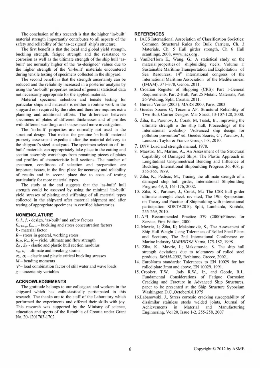
The conclusion of this research is that the higher ‘in-built’ material strength importantly contributes to all aspects of the safety and reliability of the ‘as-designed’ ship’s structure. The first benefit is that the local and global yield strength, buckling strength, fatigue strength and the resistance to corrosion as well as the ultimate strength of the ship hull ‘as-built’ are normally higher of the ‘as-designed’ values due to the higher strength of the ‘in-built’ materials encountered during tensile testing of specimens collected in the shipyard. The second benefit is that the strength uncertainty can be reduced and the reliability increased in a posterior analysis by using the ‘as-built’ properties instead of general statistical data not necessarily appropriate for the applied material. Material specimen selection and tensile testing for particular ships and materials is neither a routine work in the shipyard nor required by the rules and therefore requires extra planning and additional efforts. The differences between specimens of plates of different thicknesses and of profiles with different scantlings and shapes need more investigation. The ‘in-built’ properties are normally not used in the structural design. That makes the genuine ‘in-built’ material property assessment expedient after the material delivery to the shipyard’s steel stockyard. The specimen selection of ‘in-built’ materials can appropriately take place in the cutting and section assembly workshops from remaining pieces of plates and profiles of characteristic hull sections. The number of specimen, conditions of selection and preparation are important issues, in the first place for accuracy and reliability of results and in second place due to costs of testing particularly for more material types. The study at the end suggests that the ‘as-built’ hull strength could be assessed by using the minimal ‘in-built’ yield stresses of plating and stiffening of all material types collected in the shipyard after material shipment and after testing of appropriate specimens in certified laboratories. NOMENCLATURE fd, fa, fs - design, ‘as-built’ and safety factors fbuckling, fstress – buckling and stress concentration factors k - material factor R – stress in general, working stress ReH, Rm, Rf – yield, ultimate and flow strength ZR , ZP - elastic and plastic hull section modulus εm, εu – ultimate and breaking strains σE, σc – elastic and plastic critical buckling stresses M – bending moments Ψ – load combination factor of still water and wave loads χ – uncertainty variables ACKNOWLEDGEMENTS
The gratitude belongs to our colleagues and workers in the shipyard which has enthusiastically participated in this research. The thanks are to the staff of the Laboratory which performed the experiments and offered their skills with joy. This research was supported by the Ministry of science, education and sports of the Republic of Croatia under Grant No. 20-1201703-1702.
REFERENCES 1. IACS International Association of Classification Societies:
Common Structural Rules for Bulk Carriers, Ch. 3 Materials, Ch. 5 Hull girder strength, Ch 6 Hull scantlings, 2008, www.iacs.org .
2. VanDerHorn E., Wang. G.: A statistical study on the material properties of shipbuilding steels; Volume 1: Sustainable Maritime Transportation and Exploitation of Sea Resources; 14th international congress of the International Maritime Association of the Mediterranean (IMAM), 371–378, Genoa, 2011.
3. Croatian Register of Shipping (CRS): Part 1-General Requirements, Part 2-Hull, Part 25 Metalic Materials, Part 26-Welding, Split, Croatia, 2011.
4. Bureau Veritas (2003): MARS 2000, Paris, 2003. 5. Guedes Soares C, Teixeira AP. Structural Reliability of
Two Bulk Carrier Designs. Mar Struct, 13-107-128, 2000. 6. Žiha, K., Parunov, J., Ćorak, M, Tušek, B., Improving the
ultimate strength o the ship hull, Proceedings of the International workshop "Advanced ship design for pollution prevention" ed. Guedes Soares, C ; Parunov, J., London : Taylor & Francis Group, 1-8, 2010.
7. DNV Load and strength manual, 1978. 8. Maestro, M., Marino, A., An Assessment of the Structural
Capability of Damaged Ships: The Plastic Approach in Longitudinal Unsymmetrical Bending and Influence of Buckling, International Shipbuilding Progress 36, 408, p. 355-365. 1989.
9. Ziha, K., Pedisic, M., Tracing the ultimate strength of a damaged ship hull girder, International Shipbuilding Progress 49, 3, 161-176, 2002.
10. Ziha, K., Parunov, J., Ćorak, M.: The CSR hull girder ultimate strenght check revisited, The 19th Symposium on Theory and Practice of Shipbuilding with international participation SORTA2010, Split, Lumbarda, Korčula, 255-269, 2010.
11. API Recommended Practice 579 (2000):Fitness for Service, First Edition, 2000.
12. Mavrić, I.; Žiha, K; Maksimović, S., The Assessment of Ship Hull Weight Using Tolerances of Rolled Steel Plates and Sections, The 2nd International Conference on Marine Industry MARIND'98 Varna, 175-182, 1998.
13. Ziha, K., Mavric, I.; Maksimovic, S. The ship hull strength deviations due to tolerances of rolled steel products, IMAM-2002, Rethimno, Greece, 2002..
14. EuroNorm standards: Tolerances to EN 10029 for hot rolled plate 3mm and above, EN 10029, 1991.
15. Crooker, T.W. Jody R.W., Jr., and Goode, R.J., Fundamental Considerations of Fatigue Corrosion Cracking and Fracture in Advanced Ship Structures, paper to be presented at the Ship Structure Syposium Washington D.C.,October6.8,1975
16. Labanowski, J., Stress corrosio cracking susceptability of dissimilar stainless steels welded joints, Journal of Achievements in Material and Manufacturing Enginnering, Vol 20, Issue 1-2, 255-258, 2007