StreamIt: A language for streaming applications
17
StreaMIT: A Language for Streaming Applications * Bill Thies, Michal Karczmarek, and Saman Amarasinghe Laboratory for Computer Science Massachusetts Institute of Technology Cambridge, MA 02139 {thies, karczma, saman}@lcs.mit.edu August 13, 2001 ABSTRACT We characterize high-performance streaming applications as a new and distinct domain of programs that is becoming increasingly important. The StreaMIT language provides novel high-level representations to improve programmer pro- ductivity and program robustness within the streaming do- main. At the same time, the StreaMIT compiler aims to im- prove the performance of streaming applications via stream- specific analyses and optimizations. In this paper, we moti- vate, describe and justify the language features of StreaMIT, which include: a structured model of streams, a messaging system for control, a re-initialization mechanism, and a nat- ural textual syntax. We also present a means of reasoning about time in terms of “information flow”: a concept that we believe is fundamental to the streaming domain. Using this concept, we give a formal semantics for StreaMIT’s mes- saging system, as well as a simple algorithm for detecting deadlock and buffer overlow. 1. INTRODUCTION Applications that are structured around some notion of a “stream” are becoming increasingly important and widespread. There is evidence that streaming media applications are al- ready consuming most of the cycles on consumer machines [8], and their use is continuing to grow. In the embedded domain, applications for hand-held computers, cell phones, and DSP’s are centered around a stream of voice or video data. The stream abstraction is also fundamental to high- performance applications such as intelligent software routers, cell phone base stations, and HDTV editing consoles. Despite the prevalence of these applications, there is sur- prisingly little language and compiler support for practical, large-scale stream programming. Of course, the notion of a stream as a programming abstraction has been around for decades [2], and a number of special-purpose stream lan- guages have been designed (see [9] for a review). Many of these languages and representations are elegant and theo- retically sound, but they often lack features and are too inflexible to support straightforward development of mod- ern stream applications, or their implementations are too inefficient to use in practice. * This document is MIT/LCS Technical Memo LCS- TM-620, August 2001. A similar version was submitted to POPL 2002. Please do not distribute. Consequently, most programmers turn to general-purpose languages such as C or C++ to implement stream programs, resorting to low-level assembly codes for performance-critical loops. This practice is labor-intensive, error-prone, and very costly, since the performance-critical sections must be re- implemented for each target architecture. Moreover, general purpose languages do not provide a natural and intuitive representation of streams, thereby having a negative effect on readability, robustness, and programmer productivity. StreaMIT is a language and compiler specifically designed for modern stream programming. Its goals are two-fold: first, to raise the abstraction level in stream programming, thereby improving programmer productivity and program robustness, and second, to provide a compiler that performs stream-specific optimizations to achieve the performance of an expert assembly programmer. To address the first of these goals, this paper motivates, describes, and justifies StreaMIT’s high-level language fea- tures. The version of StreaMIT described in this paper re- quires static flow rates in the streams; applications such as compression that have dynamic flow rates will be the subject of future work. This paper also presents a notion of “infor- mation flow” that we believe is fundamental to the stream- ing domain. Using this notion, we give a clear semantics to StreaMIT’s messaging system and describe simple algo- rithms for static deadlock and overflow detection. This paper is organized as follows. In Section 2, we char- acterize the domain of streaming programs that motivates the design of StreaMIT. In Section 3, we provide a detailed description of StreaMIT, and in Section 4 we formally define the semantics of StreaMIT using a notion of “information flow”. We present a detailed example of a software radio in Section 5 and describe related work in Section 6. Sec- tion 7 contains our conclusions, and the Appendix gives an overview of StreaMIT syntax. 2. STREAMING APPLICATION DOMAIN The applications that make use of a stream abstraction are diverse, with targets ranging from embedded devices, to con- sumer desktops, to high-performance severs. However, we have observed a number of properties that these programs have in common–enough so as to characterize them as be- 1
-
Upload
independent -
Category
Documents
-
view
5 -
download
0
Transcript of StreamIt: A language for streaming applications
StreaMIT: A Language for Streaming Applications∗
Bill Thies, Michal Karczmarek, and Saman Amarasinghe
Laboratory for Computer ScienceMassachusetts Institute of Technology
Cambridge, MA 02139
{thies, karczma, saman}@lcs.mit.edu
August 13, 2001
ABSTRACTWe characterize high-performance streaming applications asa new and distinct domain of programs that is becomingincreasingly important. The StreaMIT language providesnovel high-level representations to improve programmer pro-ductivity and program robustness within the streaming do-main. At the same time, the StreaMIT compiler aims to im-prove the performance of streaming applications via stream-specific analyses and optimizations. In this paper, we moti-vate, describe and justify the language features of StreaMIT,which include: a structured model of streams, a messagingsystem for control, a re-initialization mechanism, and a nat-ural textual syntax. We also present a means of reasoningabout time in terms of “information flow”: a concept thatwe believe is fundamental to the streaming domain. Usingthis concept, we give a formal semantics for StreaMIT’s mes-saging system, as well as a simple algorithm for detectingdeadlock and buffer overlow.
1. INTRODUCTIONApplications that are structured around some notion of a“stream” are becoming increasingly important and widespread.There is evidence that streaming media applications are al-ready consuming most of the cycles on consumer machines[8], and their use is continuing to grow. In the embeddeddomain, applications for hand-held computers, cell phones,and DSP’s are centered around a stream of voice or videodata. The stream abstraction is also fundamental to high-performance applications such as intelligent software routers,cell phone base stations, and HDTV editing consoles.
Despite the prevalence of these applications, there is sur-prisingly little language and compiler support for practical,large-scale stream programming. Of course, the notion of astream as a programming abstraction has been around fordecades [2], and a number of special-purpose stream lan-guages have been designed (see [9] for a review). Many ofthese languages and representations are elegant and theo-retically sound, but they often lack features and are tooinflexible to support straightforward development of mod-ern stream applications, or their implementations are tooinefficient to use in practice.
∗This document is MIT/LCS Technical Memo LCS-TM-620, August 2001. A similar version was submitted toPOPL 2002. Please do not distribute.
Consequently, most programmers turn to general-purposelanguages such as C or C++ to implement stream programs,resorting to low-level assembly codes for performance-criticalloops. This practice is labor-intensive, error-prone, and verycostly, since the performance-critical sections must be re-implemented for each target architecture. Moreover, generalpurpose languages do not provide a natural and intuitiverepresentation of streams, thereby having a negative effecton readability, robustness, and programmer productivity.
StreaMIT is a language and compiler specifically designedfor modern stream programming. Its goals are two-fold:first, to raise the abstraction level in stream programming,thereby improving programmer productivity and programrobustness, and second, to provide a compiler that performsstream-specific optimizations to achieve the performance ofan expert assembly programmer.
To address the first of these goals, this paper motivates,describes, and justifies StreaMIT’s high-level language fea-tures. The version of StreaMIT described in this paper re-quires static flow rates in the streams; applications such ascompression that have dynamic flow rates will be the subjectof future work. This paper also presents a notion of “infor-mation flow” that we believe is fundamental to the stream-ing domain. Using this notion, we give a clear semanticsto StreaMIT’s messaging system and describe simple algo-rithms for static deadlock and overflow detection.
This paper is organized as follows. In Section 2, we char-acterize the domain of streaming programs that motivatesthe design of StreaMIT. In Section 3, we provide a detaileddescription of StreaMIT, and in Section 4 we formally definethe semantics of StreaMIT using a notion of “informationflow”. We present a detailed example of a software radioin Section 5 and describe related work in Section 6. Sec-tion 7 contains our conclusions, and the Appendix gives anoverview of StreaMIT syntax.
2. STREAMING APPLICATION DOMAINThe applications that make use of a stream abstraction arediverse, with targets ranging from embedded devices, to con-sumer desktops, to high-performance severs. However, wehave observed a number of properties that these programshave in common–enough so as to characterize them as be-
1

ReadFromAtoD RFtoIF
Booster
FFT CheckFreqHop CheckQuality AudioBackEnd
Figure 1: A block diagram of a software radio. A detailed StreaMIT implementation appears in Figure 17.
longing to a distinct class of programs, which we will referto as streaming applications. The following are the salientproperties of a streaming application, independent of its im-plementation:
1. Large streams of data. Perhaps the most fundamentalaspect of a streaming application is that it operates ona large (or virtually infinite) sequence of data items,hereafter referred to as a data stream. Data streamsgenerally enter the program from some external source,and each data item is processed for a limited time be-fore being discarded. This is in contrast to scientificapplications, in which a fixed input set is manipulatedwith a large degree of data reuse.
2. Independent stream filters. Conceptually, a streamingcomputation represents a sequence of transformationson the data streams in the program. We will refer tothe basic unit of this transformation as a filter: an op-eration that–on each execution step–reads one or moreitems from an input stream, performs some computa-tion, and writes one or more items to an output stream.Filters are generally independent and self-contained,without references to global variables or other filters.A stream program is the composition of filters into astream graph, in which the outputs of some filters areconnected to the inputs of others.
3. A stable computation pattern. The structure of thestream graph is generally constant during the steady-state operation of a stream program. That is, a certainset of filters are repeatedly applied in a regular, pre-dictable order to produce an output stream that is agiven function of the input stream.
4. Occasional modification of stream structure. Even thougheach arrangement of filters is executed for a long time,there are still dynamic modifications to the streamgraph that occur on occasion. For instance, if a wire-less network interface is experiencing high noise on aninput channel, it might react by adding some filtersto clean up the signal; a software radio re-initializes aportion of the stream graph when a user switches fromAM to FM. Sometimes, these re-initializations are syn-chronized with some data in the stream–for instance,when a network protocol changes from bluetooth to802.11 at a certain point of a transmission. Thereis typically an enumerable number of configurationsthat the stream graph can adopt in any one program,such that all of the possible arrangements of filters areknown at compile time.
5. Occasional out-of-stream communication. In additionto the high-volume data streams passing from one fil-ter to another, filters also communicate small amountsof control information on an infrequent and irregular
class FIR extends Filter {Channel input = new FloatChannel();Channel output = new FloatChannel();int N;
void init(int N) {this.N = N;
}
void work() {float sum = 0;for (int i=0; i<N; i++)
sum += input.peek(i)*FIR_COEFF[i][N];input.pop();output.push(sum);
}}
class Main extends Stream {void init() {
add(new DataSource());add(new FIR(N));add(new Display());
}}
Figure 2: An FIR filter in StreaMIT.
basis. Examples include changing the volume on a cellphone, printing an error message to a screen, or chang-ing a coefficient in an upstream FIR filter.
6. High performance expectations. Often there are real-time constraints that must be satisfied by streamingapplications; thus, efficiency (in terms of both latencyand throughput) is of primary concern. Additionally,many embedded applications are intended for mobileenvironments where power consumption, memory re-quirements, and code size are also important.
3. LANGUAGE OVERVIEWStreaMIT includes stream-specific abstractions and repre-sentations that are designed to improve programmer pro-ductivity for the domain of programs described above. Inthis paper, we present StreaMIT in legal Java syntax for easeof presentation. Though this syntax can express the funda-mental ideas of StreaMIT, in the longer term we plan todevelop a cleaner and more abstract syntax that is designedspecifically for stream programs.
Figure 17 contains a detailed example of a software radioimplemented in StreaMIT; a block diagram of the systemappears in Figure 1. In the following sections, we draw ondifferent components of this example to describe and justifythe major features of StreaMIT. A more detailed guide tothe syntax of StreaMIT can be found in the Appendix.
3.1 Filters3.1.1 StreaMIT ApproachThe basic unit of computation in StreaMIT is the Filter.An example of a Filter is the FIRFilter, a component of our
2

int N = 5;int BLOCK_SIZE = 100;
void step(float[] input, float[] output, int numIn, int numOut) {float sum = 0;for (int k=0; k<numIn; k++)
sum = sum + input[k]*FIR_COEFF[k+numIn][N];for (int k=numIn; k<N; k++)
sum = sum + input[k]*FIR_COEFF[k-numIn][N];output[numOut] = sum;input[numIn] = getData();
}
void main() {float input[] = new float[N];float output[] = new float[BLOCK_SIZE];int numIn, numOut;
for (numIn=0; numIn<N; numIn++)input[numIn] = getData();
while (true) {
for (out=0; numIn<N; numIn++, numOut++)step(input, output, numIn, numOut);
int wholeSteps = (BLOCK_SIZE-numOut)/N;for (int k=0; k<wholeSteps; k++) {
for (numIn=0; numIn<N; numIn++, numOut++)step(input, output, numIn, numOut);
for (numIn=0; numOut<BLOCK_SIZE; numIn++, numOut++)step(input, output, numIn, numOut);
displayBlock(output);}
}
Figure 3: An optimized FIR filter in a procedural lan-guage. A complicated loop nest is required to avoid
mod functions and to use memory efficiently, and the
structure of the loops depends on the data rates (e.g.,
BLOCK SIZE) within the stream. An actual implemen-
tation might inline the calls to step.
software radio (see Figure 2). Each Filter contains an initfunction that is called at initialization time; in this case, theFIRFilter records N, the number of items it should filter atonce. A user should instantiate a filter by using its construc-tor, and the init function will be called implicitly with thesame arguments that were passed to the constructor1.
The work function describes the most fine grained execu-tion step of the filter in the steady state. Within the workfunction, the filter can communicate with neighboring blocksusing the input and output channels, which are typed FIFOqueues declared as fields at the top of the class. These high-volume channels support the three intuitive operations:
1. pop() removes an item from the end of the channeland returns its value.
2. peek(i) returns the value of the item i spaces fromthe end of the channel without removing it.
3. push(x) writes x to the front of the channel. Theargument x is passed by value; if it is an object, aseparate copy is enqueued on the channel.
1This design might seem unnatural, but it is necessary toallow inlining (Section 3.2) and re-initialization (Section 3.4)within a Java-based syntax.
class FIRFilter {int N;float[] input;
FIRFilter(int N) {this.N = N;
}
float[] getData(float[] output, int offset, int length) {if (input==null) {
input = new float[MAX_LENGTH];source.getData(input, 0, N+length);
} else {source.getData(input, N, length);
}
for (int i=0; i<length; i++) {float sum = 0;for (int j=0; j<N; j++) {
sum = sum + data1[i+j]*FIR_COEFF[j][N];}output[i+offset] = sum;
}
for (int i=0; i<N; i++) {input[i] = input[i+length];
}}
}
void main() {
DataSource datasource = new DataSource();FIRFilter filter = new FIRFilter(5);Display display = new Display();filter.source = datasource;display.source = filter;display.run();
}
Figure 4: An FIR filter in an object oriented language.A “pull model” is used by each filter object to retrieve
a chunk of data from its source, and straight-line code
connects one filter to another.
A filter can also push, pop, and peek items from within theinit function if it needs to set up some initial state on itschannels, although this usually is not necessary.
A major restriction of the current version of StreaMIT isthat it requires filters to have static input and output rates.That is, the number of items peeked, popped, and pushedby each filter must be constant from one invocation of thework function to the next. We plan to support dynamicallychanging rates in a future version of StreaMIT.
3.1.2 RationaleStreaMIT’s representation of a filter is an improvement overgeneral-purpose languages. In a procedural language, theanalog of a filter is a block of statements in a complicatedloop nest (see Figure 3). This representation is unnatural forexpressing the feedback and parallelism that is inherent instreaming systems. Also, there is no clear abstraction bar-rier between one filter and another, and high-volume streamprocessing is muddled with global variables and control flow.The loop nest must be re-arranged if the input or output ra-tios of a filter changes, and scheduling optimizations furtherinhibit the readability of the code. In contrast, StreaMITplaces the filter in its own independent unit, making explicitthe parallelism and inter-filter communication while hidingthe grungy details of scheduling and optimization from theprogrammer.
3

class FFT extends Stream {void init(int N) {
add(new SplitJoin() {void init() {
setSplitter(WEIGHTED_ROUND_ROBIN(N/2, N/2));for (int i=0; i<2; i++)
add(new SplitJoin() {void init() {
setSplitter(ROUND_ROBIN);add(IDENTITY());add(IDENTITY());setJoiner(WEIGHTED_ROUND_ROBIN(N/4, N/4);
}});setJoiner(ROUND_ROBIN);
}});for (int i=2; i<N; i*=2)
add(new Butterfly(i, N));}}
Figure 5: A Fast Fourier Transform (FFT) in StreaMIT.
One could also use an object-oriented language to imple-ment a stream abstraction (see Figure 4). This avoids someof the problems associated with a procedural loop nest, butthe programming model is again complicated by efficiencyconcerns. That is, a runtime library usually exectutes filtersaccording to a pull model, where a filter operates on a blockof data that it retrieves from the input channel. The blocksize is often optimized for the cache size of a given archi-tecture, which hampers portability. Moreover, operating onlarge-grained blocks obscures the fundamental fine-grainedalgorithm that is visible in a StreaMIT filter. Thus, the ab-sence of a runtime model in favor of automated schedulingand optimization again distinguishes StreaMIT.
3.2 Connecting Filters3.2.1 StreaMIT ApproachThe basic construct for composing filters into a communi-cating network is a Stream. The FFT in Figure 5 is anexample of a Stream that appears in our software radio.Like a Filter, a Stream has an init function that is calledupon its instantiation. However, there is no work function,and all input and output channels are implicit; instead, thestream behaves as the sequential composition of filters thatare specified with successive calls to add from within init.That is, Stream creates a single pipeline.
There are two other stream constructors besides Stream:SplitJoin and FeedbackLoop. The former is used to specifyindependent parallel streams that diverge from a commonsplitter and merge into a common joiner. There are threekinds of splitters:
1. WEIGHTED ROUND ROBIN(i1, i2, . . . , ik), whichsends the first i1 data items to the first stream, thenext i2 data items to the second stream, and so on.
2. ROUND ROBIN, which is just a weighted round robinwhere all weights are 1.
3. DUPLICATE, which replicates each data item andsends a copy to each parallel stream.
4. NULL, which means that all of the parallel compo-nents are sources and there is no input to split.
Similarly, there are three kinds of joiners:
StreamStream Stream
(a) A Stream.
Stream
Stream
JoinSplit
(b) A SplitJoin.
Join
Stream
Stream Split
(c) A FeedbackLoop.
Figure 6: Stream structures supported byStreaMIT.
1. WEIGHTED ROUND ROBIN(i1, i2, . . . , ik), whichreads the first i1 data items from the first stream, thenext i2 data items to the second stream, and so on.
2. ROUND ROBIN, which is just a weighted round robinwhere all weights are 1.
3. COMBINE, which reads from all the streams in par-allel and combines the results into a structure. Thestructure has a separate field for each stream, and thejoiner cannot fire until each field is filled by an itemfrom the corresponding output channel.
4. NULL, which means that all of the parallel compo-nents are sinks and there is no output to join together.
The splitter and joiner type are specified with calls to setSplitterand setJoiner, respectively (see Figure 5); the parallel streamsare specified by successive calls to add, with the i’th call set-ting the i’th stream in the SplitJoin . Note that aWEIGHTED ROUND ROBINcan function as an exclusive selector if one or more of theweights are zero. Also, there are additional splitters andjoiners that we plan to add when StreaMIT supports filterswith dynamically changing rates, including:
1. TYPE DISPATCH, which sends an item to one of mul-tiple streams depending on its type.
2. ANY, which sends items to any parallel stream thathas space on its input, or reads items from any parallelstream that has output available.
The last control construct provides a way to create cycles inthe stream graph: the FeedbackLoop. It contains a joiner,
4

class Fibonnacci extends FeedbackLoop {void init() {
setDelay(2);setJoiner(WEIGHTED_ROUND_ROBIN(0,1));setBody(new Filter() {
Channel input = new IntChannel();Channel output = new IntChannel();void work() {
output.push(input.peek(0)+input.peek(1));input.pop();
}});setSplitter(DUPLICATE);
}
int initPath(int index) {return index;
}}
Figure 7: A FeedbackLoop version of Fibonnacci.
a body stream, a splitter, and a loop stream, which areset with calls to setJoiner, setBody, setSplitter, andsetLoop, respectively (see Figure 7). The splitters and join-ers can be any of those for SplitJoin, except for NULL.
The feedback loop has a special semantics when the streamis first starting to run. Since there are no items on the feed-back path at first, the stream instead inputs items from aninitPath function defined by the FeedbackLoop; initPathis called with the number of the data item that is beingfabricated (starting from 0). With a call to setDelay fromwithin the init function, the user can specify how manyitems should be calculated with initPath before the joinerlooks for data items from the feedback channel.
Evident in all of these examples is another feature of theStreaMIT syntax: inlining. The definition of any stream orfilter can be inlined at the point of its instantiation, therebypreventing the definition of many small classes that are usedonly once, and, moreover, providing a syntax that revealsthe hierarchical structure of the streams from the indenta-tion level of the code. In our Java syntax, we make use ofanonymous classes for inlining [5].
3.2.2 RationaleStreaMIT differs from other languages in that it imposes awell-defined structure on the streams; all stream graphs arebuilt out of a hierarchical composition of Streams, SplitJoins,and FeedbackLoops. This is in contrast to other environ-ments, which generally regard a stream as a flat and ar-bitrary network of filters that are connected by channels.However, arbitrary graphs are very hard for the compiler toanalyze, and equally difficult for a programmer to describe.Most programmers either resort to straight-line code thatlinks one filter to another (thereby making it very hard tovisualize the stream graph), or using an ad-hoc graphicalprogramming environment that is awkward to use and ad-mits no good textual representation.
In contrast, StreaMIT is a clean textual representation that–especially with inlined streams–makes it very easy to see theshape of the computation from the indentation level of thecode. The comparison of StreaMIT’s structure with arbi-trary stream graphs could be likened to the difference be-tween structured control flow and GOTO statements. Thoughsometimes the structure restricts the expressiveness of the
class TrunkedRadio extends Stream {RFtoIFPortal freqHop = new RFtoIFPortal();...void init() {
...RFtoIF rf2if;add(rf2if = new RFtoIF(STARTFREQ));freqHop.register(rf2if);...add(new CheckFreqHop(freqHop));...
}}
class RFtoIF extends Filter {...// sets frequency to <f>void setf(float f) {
...}
}
class CheckFreqHop extends SplitJoin {RFtoIFPortal freqHop;
void init(RFtoIFPortal freqHop) {this.freqHop = freqHop;...add(new Filter() {
...void work() {
...if(val >= MIN_THRESHOLD)
freqHop.setf(Freq[k], new TimeInterval(4*N, 6*N));...
}});...
}}
Figure 8: The frequency-hopping of our softwareradio illustrates StreaMIT’s messaging system. InTrunkedRadio, a Portal is created to hold the messagetarget, rf2if. Then, CheckFreqHop uses the Portal tosend a frequency-change message.
programmer, the gains in robustness, readability, and com-piler analysis are immense.
A final benefit of stream graph construction in StreaMIT isthe ability to do scripting to parameterize graphs. For in-stance, both the FFT stream in Figure 5 inputs a parameterN and adjusts the number of butterfly stages appropriately.This further improves readability and decreases code size.
3.3 Messages3.3.1 StreaMIT ApproachStreaMIT provides a dynamic messaging system for pass-ing irregular, low-volume control information between fil-ters and streams. Messages are sent from within the bodyof a filter’s work function, perhaps to change a parameterin another filter. For example, in the CheckFreqHop streamof our software radio example (Figure 8), a message is sentupstream to change the frequency of the receiver if the down-stream component detects that the transmitter is about tochange frequencies. The sender can continue to executewhile the message is en route, and the set freq methodwill be invoked in the receiver with argument Freq[k] whenthe message arrives. Since message delivery is asynchronous,there can be no return value; only void methods can be mes-sage targets.
Message timing.The central aspect of the messaging sys-tem is a sophisticated timing mechanism that allows filtersto specify when a message will be received relative to theflow of information between the sender and the receiver.
5

Recall that each filter executes independently, without anynotion of global time. Thus, the only way for two filters totalk about a time that is meaningful for both of them is interms of the data items that are passed through the streamsfrom one to the other.
In StreaMIT, one can specify a range of latencies for a mes-sage to get delivered. This latency is measured in termsof an information “wavefront” from one filter to another.For example, in the CheckFreqHop example of Figure 8, thesender indicates an interval of latencies between 4N and6N . This means that the receiver will receive the messageimmediately following the last invocation of its own work
function which produces an item affecting the some outputof the sender’s 4N ’th to 6N ’th work functions, counting thesender’s current work function as number 0. Defining thisnotion precisely is the subject of Section 4, but the generalidea is simple: the receiver is invoked when it sees the infor-mation wavefront that the sender sees in 4N to 6N executionsteps.
In some cases, the ability to synchronize the arrival of amessage with some element of the data stream is very im-portant. For example, CheckFreqHop knows that the trans-mitter will change the frequency between 4N and 6N stepslater, in terms of the frame that CheckFreqHop is inputting.To ensure that the radio changes frequencies at the sametime–so as not to lose any data at the old or new frequency–CheckFreqHop instructs the receiver to switch frequencieswhen the receiver sees one of the last data items at the oldfrequency.
If the receiver of a message is a stream instead of a filter,then the message delivery is timed with respect to the first(most upstream) filter in the stream. We are still formalizingthe message delivery semantics in cases where the receiveris a stream that has no unique first filter (e.g., a SplitJoinwith NULL splitter). Note that the stream itself can receivea message even though the timing is in terms of filter-to-filter communication.
Portals for broadcast messaging. StreaMIT also hassupport for modular broadcast messaging. When a senderwants to send a message that will invoke method M of thereceiver R upon arrival, it does not call M on the objectR. Rather, it calls M on a Portal of which R is a member.Portals are typed containers that forward all messages theyreceive to the elements of the container. Portals could beuseful in cases when a component of a filter library needs toannounce a message (e.g., that it is shutting down) but doesnot know the list of recipients; the user of the library canpass the filter a Portal containing all interested receivers. Asfor message delivery constraints, the user specifies a singletime interval for each message, and that interval is inter-preted separately (as described above) for each receiver inthe Portal.
In a language with generic data types, a Portal could beimplemented as a templated list. However, since Java doesnot yet support templates, we automatically generate an<X>Portal class for every class and interface <X>. Our syn-tax for using Portals is evident in the TrunkedRadio class inFigure 8.
3.3.2 RationaleStream programs present a challenge in that filters needboth regular, high-volume data transfer and irregular, low-volume control communication. Moreover, there is the prob-lem of reasoning about the relative “time” between filterswhen they are running asynchronously and in parallel.
A different approach to messaging is to embed control mes-sages in the data stream instead of providing a separatemechanism for dynamic message passing. This does havethe effect of associating the message time with a data item,but it is complicated, error-prone, and leads to unreadablecode. Further, it could hurt performance in the steady state(if each filter has to check whether or not a data item isactual data or control, instead) and complicates compileranalysis, too. Finally, one can’t send messages upstreamwithout creating a separate data channel for them to travelin.
Another solution is to treat messages as synchronous methodcalls. However, this delays the progress of the stream whenthe message is en route, thereby degrading the performanceof the program and restricting the compiler’s freedom toreorder filter executions.
We feel that the StreaMIT messaging model is an advance inthat it separates the notions of low-volume and high-volumedata transfer–both for the programmer and the compiler–without losing a well-defind semantics where messages aretimed relative to the high-volume data flow. Further, byseparating message communication into its own category,fewer connections are needed for steady-state data trans-fer and the resulting stream graphs are more amenable tostructured stream programming.
3.4 Re-Initialization
3.4.1 StreaMIT ApproachOne of the characteristics of a streaming application is theneed to occaisionally modify the structure of part of thestream graph. StreaMIT allows these changes through a re-initialization mechanism that is integrated with its messag-ing model. If a sender targets a message at the init functionof a stream or filter S, then when the message arrives, it re-executes the initialazation code and replaces S with a newversion of itself. However, the new version might have adifferent structure than the original if the arguments to theinit call on re-initialization were different than during theoriginal initialization.
When an init message arrives, it does not kill all of the datathat is in the stream being re-initialized. Rather, it drainsthe stream until the wavefront of information (as defined forthe messaging model) from the top of the stream has reachedthe bottom. The draining occurs without consuming anydata from the input channels to the re-initialized region.Instead, a drain function of each filter is invoked to pro-vide input when its other input source is frozen. (Each filtercan override the drain function as part of its definition.) Ifthe programmer prefers to kill the data in a stream segmentinstead of draining it, this can be indicated by sending an ex-tra argument to the message portal with the re-initializationmessage.
6
3.4.2 RationaleRe-initialization is a headache for stream programmers because–if done manually–the entire runtime system could be puton hold to re-initialize a portion of the stream. The inter-face to starting and stopping streams could be complicatedwhen there is not an explicit notion of initialization time vs.steady-state execution time, and ad-hoc draining techniquescould risk losing data or deadlocking the system.
StreaMIT improves on this situation by abstracting the re-initialization process from the user. That is, no auxillarycontrol program is needed to drain the old streams and cre-ate the new structure; the user need only trigger the reini-tialization process through a message. Additionally, anyhierarchical stream construct automatically becomes a pos-sible candidate for re-initialization, due to the well-definedstream structure and the simple interface with the init
function. Finally, it is easy for the compiler to recognizestream re-initialization possibilities and to account for allpossible configurations of the stream flow graph during anal-ysis and optimization.
3.5 Latency ConstraintsLastly, StreaMIT provides a simple way of restricting thelatency of an information wavefront in traveling from theinput of one filter to the output of a downstream filter. Is-sueing the directive MAX LATENCY(A, B, n) from within aninit means that A can only execute up to the wavefront ofinformation that B will see after n invocations of its ownwork function.
In the case that A is a stream instead of a filter, then thelatency is with regards to the most upstream filter of A;likewise, if B is a stream, then the latency is with regards tothe most downstream filter in B. We are still in the processof formalizing the semantics in cases when there is no uniqueupstream or downstream filter in these streams.
4. SEMANTICS OF TIMEIn this section we develop a more formal semantics for themessage delivery guarantees described above. The timingmodel in StreaMIT is unique in that all time is relative toinformation wavefronts–that is, two independent filters candescribe a common time only in terms of when the effects ofone filter’s execution are seen by the other. Thus, althougheach filter’s work function is invoked asynchronously withoutany notion of global time, two invocations of a work functionoccur at the same “information-relative time” if they operateon the same information wavefront.
To define this notion more precisely, we present transferfunctions that describe the flow of information across fil-ters and streams. Using these transfer functions, we trans-late message delivery constraints into a set of constraintson the execution schedule of the stream graph. Finally, weuse these scheduling constraints to formulate an operationalsemantics for messaging and latency in StreaMIT.
4.1 Information FlowThe concept of information flow is central to the streamingdomain. When an item enters a stream, it carries with itsome new information. As execution progresses, this infor-mation cascades through the stream, effecting the state of
Filter
1
2
3
1
2
3
4
5
6
7
8
9
10
11
6
4
5
1
2
3
4
5
6
7
8
9
10
11
1
2
3
4
5
67
8
9
5
6
7
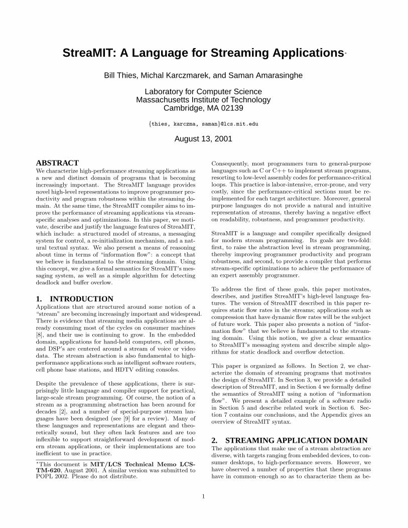
Figure 9: A filter’s input and output tapes during anexecution step. With each step, the filter pushes twoitems, pops two items, and peeks at three additionalitems. The initial state of the input tape is shownat left. The center shows the filter with both inputand output tapes during the invocation of work. Thefinal state of the output tape is shown at right
filters and the values of new data items which are produced.We refer to an “information wavefront” as the sequence offilter executions that first sees the effects of a given inputitem. This wavefront is well-defined even in the presence ofrate-changing filters that peek or pop a different number ofitems than they push. To formalize the wavefront, we intro-duce some new representations for the state of the streamgraph. Consider that in place of each data channel there isan infinite “tape” which contains the history of values thathave been pushed onto the channel (see Figure 9). Nowconsider the following functions:
• Given that there are x items on tape a, the maxi-mum number of items that can appear on tape b ismaxa→b(x).
• Given that there are x items on tape b, the mini-mum number of items that must appear on tape ais mina←b(x).
Note that these functions are only defined over pairs of tapes(a, b) where a is upstream of b–that is, where there is a di-rected path in the stream graph from the filter following ato the filter preceding b. We will say that the filter b isdownstream of a under exactly these same conditions.
The max and min functions are related to the informationwavefront in the following sense. The item at position y =mina←b(x) of tape a is the latest item on tape a to affectthe item at position x of tape b. This is because item xon tape b can be produced if and only if tape a contains atleast y items. Note that this effect might be via a controldependence rather than a data dependence–for instance, ifitem y needed to pass through a round-robin joiner beforesome data from another stream could be routed to tape b.However, when speaking of the information wavefront, weonly consider information passed through the data streams;if a data item affects another via a low-latency downstreammessage, then this effect could jump ahead of the wavefront.
We now turn to deriving expressions formaxa→b andmina←b.Doing so will allow us to formalize the semantics of messag-ing and latency in StreaMIT, as well as enabling static veri-fication techniques such as deadlock and overflow detection.
7
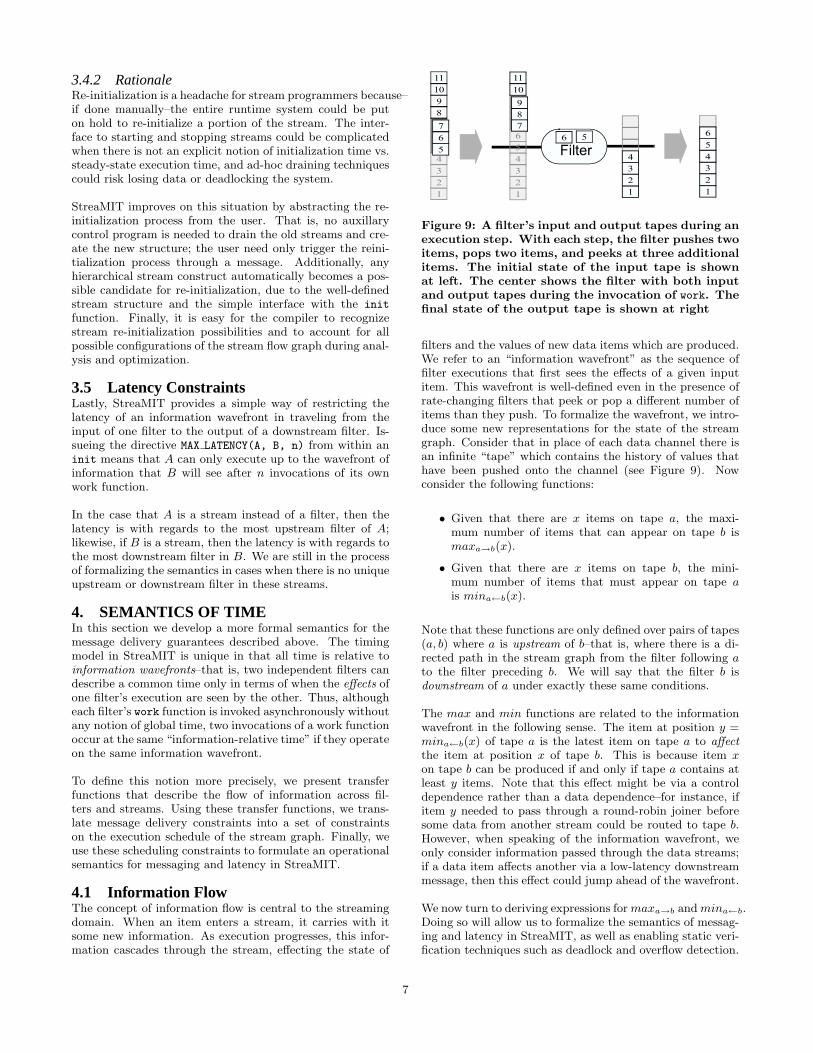
IA OA IB= OBBA
Figure 10: Stream construct with labeling.
4.1.1 FiltersConsider a filter A that peeks peekA, pops popA, and pushespushA data items on every execution step. Further, let usdenote the input and output tapes of A by IA and OA, re-spectively. We now turn our attention to findingmaxIA→OA
andminIA←OA, describing the transfer of information across
the filter A.
To derive maxIA→OA(x), observe that the filter can execute
so long as it does not peek beyond the x’th item on theinput tape, IA. After the n’th execution, it has poppedn ∗ popA items, peeked up to n ∗ popA + (peekA − popA),and pushed n ∗ pushA items. Thus, it can execute n =b(x − (peekA − popA))/popA)c times, leaving the followingexpression for maxIA→OA
(x):
maxIA→OA(x) =
pushA ∗⌊
x−(peekA−popA)popA
⌋
if x ≥ (peekA − popA)
0 if x < (peekA − popA)
By identical reasoning, the reader can verify the followingexpression for minIA←OA
(x):
minIA←OA(x) =
⌈
x
pushA
⌉
∗ popA + (peekA − popA)
4.1.2 PipelinesLet us now derive expressions for min and max in the caseof pipelined filters. In the base case, consider that two filtersare connected, with the output of A feeding into the inputof B (see Figure 10). We are seeking maxIA→OB
(x): themaximum number of items that can appear on tape OB
given that there are x items on tape IA. Observing that amaximum of maxIA→OA
(x) items can appear on tape OA,and thatOA must equal IB since the filters are connected, wesee that a maximum of maxIB→OB
(maxIA→OA(x)) items
can appear on OB :
maxIA→OB= maxIB→OB
◦maxIA→OA
In the case of minIA←OB(x), the order of composition is re-
versed: given that there are x items on tape OB , a minimumof minIB←OB
(x) are on tape IB , and since OB = IA, wehave that a minimum of minIA←OA
(minIB←OB(x)) items
appear on IA, leaving:
minIA←OB= minIA←OA
◦minIB←OB
By identical reasoning, these composition laws hold for pipelinedstreams as well as filters. That is, given tapes x, y, and z,we have that:
maxx→z = maxy→z ◦maxx→y
minx←z = minx←y ◦miny←z
(1)
However, there are some restrictions on these definitions.They only apply when there is a downstream path P1 fromthe filter following x to the filter preceding y, a downstreampath P2 from the filter following y to the filter preceding z,
OBm I2J=
OAn I1J=
BmB1
O2S IB1=
AnA1
O1S IA1=
OB1 IBm
OA1 IAn
JSIS OJ
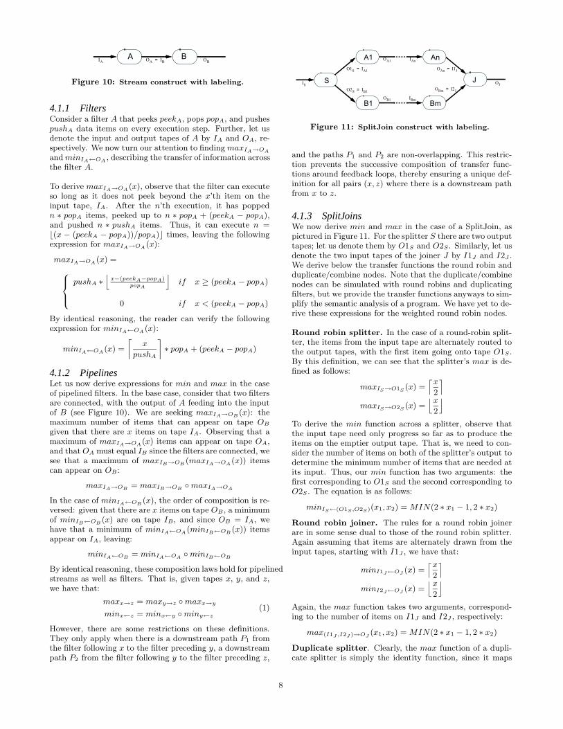
Figure 11: SplitJoin construct with labeling.
and the paths P1 and P2 are non-overlapping. This restric-tion prevents the successive composition of transfer func-tions around feedback loops, thereby ensuring a unique def-inition for all pairs (x, z) where there is a downstream pathfrom x to z.
4.1.3 SplitJoinsWe now derive min and max in the case of a SplitJoin, aspictured in Figure 11. For the splitter S there are two outputtapes; let us denote them by O1S and O2S . Similarly, let usdenote the two input tapes of the joiner J by I1J and I2J .We derive below the transfer functions the round robin andduplicate/combine nodes. Note that the duplicate/combinenodes can be simulated with round robins and duplicatingfilters, but we provide the transfer functions anyways to sim-plify the semantic analysis of a program. We have yet to de-rive these expressions for the weighted round robin nodes.
Round robin splitter. In the case of a round-robin split-ter, the items from the input tape are alternately routed tothe output tapes, with the first item going onto tape O1S .By this definition, we can see that the splitter’s max is de-fined as follows:
maxIS→O1S(x) =
⌈x
2
⌉
maxIS→O2S(x) =
⌊x
2
⌋
To derive the min function across a splitter, observe thatthe input tape need only progress so far as to produce theitems on the emptier output tape. That is, we need to con-sider the number of items on both of the splitter’s output todetermine the minimum number of items that are needed atits input. Thus, our min function has two arguments: thefirst corresponding to O1S and the second corresponding toO2S . The equation is as follows:
minIS←(O1S ,O2S)(x1, x2) =MIN(2 ∗ x1 − 1, 2 ∗ x2)
Round robin joiner. The rules for a round robin joinerare in some sense dual to those of the round robin splitter.Again assuming that items are alternately drawn from theinput tapes, starting with I1J , we have that:
minI1J←OJ(x) =
⌈x
2
⌉
minI2J←OJ(x) =
⌊x
2
⌋
Again, the max function takes two arguments, correspond-ing to the number of items on I1J and I2J , respectively:
max(I1J ,I2J )→OJ(x1, x2) =MIN(2 ∗ x1 − 1, 2 ∗ x2)
Duplicate splitter. Clearly, the max function of a dupli-cate splitter is simply the identity function, since it maps
8

OFJ IFSI1FJ O1FSFSFJ Body
I2FJ
Loop
O2FS
Figure 12: FeedbackLoop construct with labeling.
each element on the input tape to the same location on theoutput tapes:
maxIS→O1S(x) = x
maxIS→O2S(x) = x
Themin function is similar, except that–like the round robinsplit–the input need only progress as far as the lesser output:
minIS←(O1S ,O2S)(x1, x2) =MIN(x1, x2)
Combine joiner. The combine joiner is simply the dualof the duplicate splitter, with transfer functions that thereader can verify as follows:
max(I1J ,I2J )→OJ(x1, x2) =MIN(x1, x2)
minI1J←OJ(x) = x
minI2J←OJ(x) = x
4.1.4 FeedbackLoopsWe have to be careful when defining the transfer functionsfor feedback loops (see Figure 12). The feedback splitter FSserves as a normal splitter, and has the same min and maxfunctions as defined above. However, the feedback joiner FJis slightly different than a standard joiner, since during thefirst few executions it fabricates values from the loop bodybefore they appear on the input tape. The transfer functionmust take special account of these initial values, since theynever appear on I2FJ , the input tape from the loop body.This is because we model the initialization of FeedbackLoopsby feeding the joiner the initial values directly instead ofpushing them onto a channel.
Let n be the number of initial values that are provided tothe feedback joiner before values from the feedback loop areread. Let J be a normal COMBINE or ROUND ROBINjoiner as defined for SplitJoins. Now, let us define the trans-fer functions for FJ , the feedback joiner.
The min function for the main stream is as before:
minI1F J←OF J= minI1J←OJ
However, we must offset by n when considering the minfunction that draws from the loop’s tape:
minI2F J←OF J(x) = minI2J←OJ
(x)− n
Finally, the max function must be similarly shifted for theinput from the loop:
max(I1F J ,I2F J )→OF J(x1, x2) = max(I1J ,I2J )→OJ
(x1, x2 + n)
4.1.5 SummaryWe have derived expressions for maxa→b and mina←b forwhen a and b are the respective input and output to 1) a fil-ter, 2) a pipeline, 3) a split or join, and 4) a feedback split orjoin. By composing these expressions following Equation 1,we can arrive at values of maxa→b and mina←b for all pairsof tapes (a, b) where there is some directed path through thestream graph–that is, along the direction of data flow–fromthe filter reading from tape a to the filter writing to tape b.
Ommitted from the above analysis are: 1) weighted roundrobin nodes, 2) filters that push or pop items from withintheir init functions, and 3) message handlers that send mes-sages themselves. We hope to address these issues in a futuredocument.
4.2 SemanticsEquipped with definitions of maxa→b and mina←b, we cannow address the semantics of StreaMIT’s message deliveryand latency guarantees.
4.2.1 MessagesSuppose that filter A sends a message to filter B with latencyλ, where λ is any integer. In λ invocations of A’s work
function, A will produce one or more data items d. Now,the messaging system guarantees that:
1. If B is upstream of A, then B will receive the messageimmediately following the last invocation of its workfunction which produces items that affect d.
2. If B is downstream of A, then B will receive the mes-sage immediately preceding the first invocation of itswork function which produces items that are effectedby d.
3. If B runs in parallel with A, then the message timingis in terms of a shared set of splitters and joiners. Weare developing semantics for this case, but they arebeyond the scope of this paper.
These guarantees can be expressed more formally as a set ofconstraints on the number of items on certain tapes in thesystem. We will use n(t) to represent the number of itemson tape t at a given point of execution. Again, suppose thatfilter A sends a message to filter B with latency λ, where λis any integer. Let s be equal to n(OA) at the time that themessage was sent. We have that:
1. If B is upstream of A, the message will be deliveredwhen:
n(OB) = minOB←OA(s+ pushA ∗ λ) (2)
That is, s + pushA ∗ λ is the number of items on A’soutput tape after producing the data of interest. Then,y = minOB←OA
(s+pushA∗λ) is the latest item on B’soutput tape that affects the data of interest. The mes-sage should be delivered immediately after the workfunction producing this item, which occurs when theitem count n(OB) equals y, as specified by the con-straint.
9

2. If B is downstream of A, the message will be deliveredwhen:
n(OB) = maxOA→OB(s+ pushA ∗ (λ− 1)) (3)
That is, s + pushA ∗ (λ − 1) is the number of itemson A’s output tape before pushing the data of inter-est, and y = maxOA→OB
(s + pushA ∗ (λ − 1)) is themaximum number of items on B’s output tape as aresult of the outputs of A. Thus, when A pushes thenext set of data, it could affect the data that will bepushed next onto the output tape of B. (Note thatthe next set of data from A might not be sufficientto calculate the next set on B’s output, but it couldaffect it nonetheless.) The message must be deliveredimmediately before this effected data appears on B’soutput, so the number of items n(OB) on B’s outputmust equal y.
4.2.2 LatencyEach directive MAX LATENCY(A, B, n) has the same effect asdefining a message from filter B to upstream filter A withlatency n.
4.2.3 SchedulingWe can fully define the possible sequences of filter executionsas a set of constraints on the number of items on each tapein the stream graph. This is useful not only from the per-spective of semantics, but for compiler analysis of the spaceof valid schedules. To begin the analysis, we formulate theconstraints imposed by message delivery guarantees on thenumber of items on each tape.
Suppose that a filter A might send a message to filter B witha maximum latency of λ during any invocation of its workfunction. Then we must constrain the execution of B tomake sure that it is not too far ahead to receive the messagewith the given latency. That is, we can only execute B solong as n(OB)–the item count on its output tape–does notexceed the count when a message would be delivered. Re-calling the expression for message delivery time (Equations2 and 3), this constraint is as follows if B is upstream of A:
n(OB) ≤ minOB←OA(n(OA) + pushA ∗ λ) (4)
and as follows if B is downstream of A:
n(OB) ≤ maxOA→OB(n(OA) + pushA ∗ (λ− 1)) (5)
The guarantees for latency are treated identically to mes-sage guarantees, as fitting with the semantics of latency asdescribed above.
Defining the schedule. We now have a set of constraintsexpressing whether or not a given set of tapes respects thelatency and message delivery guarantees in a program. Wewill now incorporate these constraints into an operationalsemantics that defines a legal sequences of filter executions.
We represent a stream graph as a configuration (〈p(t1), n(t1)〉,〈p(t2), n(t2)〉, . . . , 〈p(tk), n(tk)〉), where p(t) represents thenumber of items that have been popped from tape t, andt1 . . . tk are the tapes in the stream graph. Obviously, wehave the constraint that p(t) ≤ n(t) for each tape t, since afilter can only pop as many items as have appeared on itsinput tape.
When the program begins, no items have been pushed orpopped from any data channels. Thus, each tape is empty,and the starting configuration C0 is simply the zero vector.It is possible that the initial configuration violates some ofthe constraints imposed by the messaging and latency con-structs, in which case the compiler can inform the program-mer that the delivery constraints requested in the programare unsatisfiable.
Let P(C) denote whether or not the constraints in Equa-tions 4 and 5 are satisfied for all filters in a stream graphwith configuration C. We can then write the transition func-tion between configurations as follows:
n(IA)− p(IA) ≥ peekA;(. . . , 〈p(IA), n(IA)〉, . . . , 〈p(OA), n(OA)〉, . . . );
P((. . . , 〈p(IA) + popA, n(IA)〉, . . . , 〈p(OA), n(OA) + pushA〉, . . . ));(. . . , 〈p(IA) + popA, n(IA)〉, . . . , 〈p(OA), n(OA) + pushA〉, . . . )
There are two components of this rule. On the first line, westate that, for filter A to fire, there must be at least peekA
items on A’s input tape that have not yet been popped.Secondly, we express that once A has fired, the new configu-ration must satisfy the messaging and latency constraints P.The new configuration differs from the original only in thatpopA items have been popped from A’s input and pushA
items have been pushed to A’s output.
Bounding the buffer size. It is a straightforward ex-tension to incorporate a constraint on the maximum num-ber of live items in the stream. This could be useful bothfrom a language perspective, in which a user might wish toconstrain the buffer size, or from a compiler perspective, inwhich the scheduler is interested in constraining the numberof live items.
The live items in a given configuration are those that havebeen pushed to a channel but have not yet been popped.That is, the buffer size needed for a configuration (〈p(t1), n(t1)〉,
. . . , 〈p(tk), n(tk)〉) is∑k
i=0 n(ti)−p(ti). If we wish to boundthe number of live items to MAXITEMS, then, we need onlyadd one condition to the transition rule:
n(IA)− p(IA) ≥ peekA;(. . . , 〈p(IA), n(IA)〉, . . . , 〈p(OA), n(OA)〉, . . . );
P((. . . , 〈p(IA) + popA, n(IA)〉, . . . , 〈p(OA), n(OA) + pushA〉, . . . ));∑k
i=0n(ti)− p(ti) ≤ MAXITEMS;
(. . . , 〈p(IA) + popA, n(IA)〉, . . . , 〈p(OA), n(OA) + pushA〉, . . . )
4.3 Program Veri£cationA number of program analysis techniques are also enabledby the min and max functions that we have defined. Inparticular, it is very simple to compute 1) whether or notthe program will deadlock as a result of a starved inputchannel, and 2) whether or not any buffer will grow withoutbound during the steady-state execution of the program.
Deadlock detection. The deadlock detection algorithmtakes advantage of the fact that the only loops in our streamgraph are part of a FeedbackLoop construct. A stream graphwill be deadlock-free if and only if there is no net change ofoutput rate in the feedback loop. This can be formulated interms of the max function by requiring that the wavefrontfrom the output of the feedback joiner FJ unto itself is theidentity function. However, since we were careful to leavethe max function undefined over cycles in the stream graph,
10

Z-1
Z-1
Z-1
Z-1
*
**
*
*
h5h4
h3h2
h1
Σ
Figure 13: A block diagram of a five tap FIR filter.
we define a new function maxloop that maps a given feed-back joiner to the information wavefront around the loop:
maxloopFJ→FJ(x) ≡ maxI2F J→OF J ◦maxOF J→I2F J
The order of composition is as in Equation 1 for the com-position of pipelines. Also, for the purposes of calculatingmaxloopFJ→FJ , one must assume that there are an infinitenumber of items on tape I1FJ ; that is, the join from thefeedback loop is not limited by the external data source.
Finally, we can state the constraint that the feedback loopmust respect. For a loop with declared latency λ, the loopwill neither overflow nor deadlock if:
maxloopFJ→FJ(x) = x+ λ
If maxloopFJ→FJ(x) is less than x + λ, then there will bedeadlock in the program.
Overflow detection. There are two places that a buffercan overflow in the stream graph. The first is in a feedbackloop, when maxloopFJ→FJ(x) (calculated above) is morethan x+ λ. The second case is when the parallel streams ofa split/join have different production rates. For a splitter Sand a joiner J , the production rates will cause an overflow ifand only if maxO1S→I1J
(x)−maxO2S→I2J(x) is not O(1).
This difference could be analyzed by a compiler for everySplitJoin in the stream graph to verify that no buffers willoverflow during steady-state execution.
5. DETAILED EXAMPLEThis section describes the Trunked Radio example imple-mentation in Figure 17. The trunked radio is a frequencyhopping system. The transition times between the presetfrequencies is indicated to the receiver by transmitting apreset tone. Our radio also has an FIR filter to increasethe gain of a weak signal. However, in order to save power,this filter is activated only when the signal to noise ratio islow. This implementation relies on transforming the signalinto the frequency domain for processing using a FFT. Forbrevity, we have not shown the RF processing in the front-end and the audio processing in the back-end. The code forthe trunked radio demonstrates many features of StreaMIT.
The high-level structure of the radio, graphically shown inFigure 1, is implemented in the class TrunkedRadio. Theradio has seven stages, where the first three stages operatein the time domain, the last three stages operate in the fre-quency domain, and there is a conversion phase in between.At this high level, the structure of the system is a pipelineof either six or seven stream stages. The difference is due
a0
a1
a2
a3
a4
a5
a6
a7
+
-
*
w11
*
w12
*
w13
*
w10
+
-
+
-
+
-
+
+
*
w21
*
w22
*
w23
*
w20
-
-
+
+
-
-
+
+
*
w41
*
w42
*
w43
*
w40
+
+
-
-
-
-
Figure 14: The multi-stage FFT algorithm
to the Booster stage, which can be active or inactive. Theswitching on and off of the Booster stage, which happens in-frequently, is accomplished using a reinitialization messagefrom the CheckQuality stage. We also use a message fromthe CheckFreqHop stage to the RFtoIF stage to change thebaseband when a frequency hop tone is present.
The RFtoIF stage modulates the input signal from RF toa frequency band around the current IF frequency. Thisstage is implemented as a filter that multiplies the currentsignal with a sine wave at the IF frequency. To support achange in the IF frequency when frequency hopping occurs,the filter contains a set freq method that can be invokedusing a message.
The optional Booster stage is an FIR filter that is activatedwhen the signal is hard to detect. During normal operation,however, it is deactivated to conserve power. The turningon and off of the filter is controlled by a message. The filteritself, shown in Figure 13, is implemented as a Filter thatpeeks at N elements in the input stream.
The FFT stage converts the program from the time domain tothe frequency domain using a multi-stage FFT. It is graphi-cally presented in 14. The FFT is composed of a reorderingfilter and a multi-stage butterfly filter. The StreaMIT repre-sentation of the reordering filter (a bit reverse order filter) isgiven in Figure 15. Note that the complex data re-shufflingis accomplished using a few SplitJoin constructs. A param-eterized Butterfly implementation is used to abstract themulti-stage butterfly in the FFT. As shown in Figure 16,the Butterfly filter is also implemented using a combinationof SplitJoin constructs.
The StreaMIT implementation of the FFT filter is cleanand intuitive. It already has a large amount of pipelinedparallelism. Due to the simple and straightforward mappingfrom the algorithm to the implementation, compiler analysesshould be able to extract the parallel structure of the FFTwhen hardware resources are available.
The next stage, CheckFreqHop, checks four different frequen-cies for the change frequency tone. When the stage de-tects this tone, it has to change the frequency within a timelimit. This task is accomplished by sending a message tothe RFtoIF stage. The message requires the RFtoIF stage todeliver between 4N and 6N items using the old modulationbefore changing to the new frequency.
11
The CheckQuality stage checks if the signal has a distinctfrequency spectrum. If all the frequencies have similar am-plitudes, the stage assumes that the signal-to-noise ratio islow and sends a message to activate the Booster. This mes-sage is sent using best-effort delivery.
6. RELATED WORKA large number of programming languages have included aconcept of a stream; see [9] for a survey. Those that areperhaps most related to the static-rate version of StreaMITare synchronous dataflow languages such as LUSTRE [6]and ESTEREL [3] which require a fixed number of inputsto arrive simultaneously before firing a stream node. How-ever, most special-purpose stream languages are functionalinstead of imperative, and do not contain features such asmessaging and support for modular program developmentthat are essential for modern stream applications. Also,most of these languages are so abstract and unstructuredthat the compiler cannot perform enough analysis and opti-mization to result in an efficient implementation.
At an abstract level, the stream graphs of StreaMIT share anumber of properties with synchronous dataflow (SDF) do-main as considered by the Ptolemy project [7]. Each nodein an SDF graph produces and consumes a given numberof items, and there can be delays along the arcs betweennodes (corresponding loosely to items that are peeked inStreaMIT). As in StreaMIT, SDF graphs are guaranteedto have a static schedule, testing for deadlock is decidable,and there are a number of nice scheduling results incorpo-rating code size and execution time [4]. However, previousresults on SDF scheduling do not consider constraints im-posed by point-to-point messages, and do not include a no-tion of StreaMIT’s information wavefronts, re-initialization,and programming language support.
A specification package used in industry bearing some like-ness to StreaMIT is SDL: Specificacation and DescriptionLanguage [1]. SDL is a formal, object-oriented language fordescribing the structure and behavior of large, real-time sys-tems, especially for telecommunications applications. It in-cludes a notion of asynchronous messaging based on queuesat the receiver, but does not incorporate wavefront seman-tics as does StreaMIT. Moreover, its focus is on specificationand verification whereas StreaMIT aims to produce an effi-cient implementation.
7. CONCLUSIONSThis paper presents StreaMIT, a novel language for high-performance streaming applications. Streaming programsare an emerging class of very important applications withdistinct properties from other recognized application classes.
StreaMIT aims to raise the abstraction level in stream pro-gramming, thereby improving programmer productivity andprogram robustness. This paper presents fundamental pro-gramming constructs for the Stream application domain. Itidentifies information flow as the natural model for reasoningabout streaming applications, and presents a formal defini-tion of the language using a semantics of time for StreaMIT.
The second goal of StreaMIT is to provide a compiler thatperforms stream-specific optimizations to achieve the per-
formance of an expert assembly programmer. Currently, alibrary-based implementation of StreaMIT is working. Weare starting the development of the first compiler implemen-tation of StreaMIT. Another area of future research is todevelop a clean high-level syntax for StreaMIT. The Java-based syntax has many advantages, including programmerfamiliarity, availability of compiler frameworks and a robustlanguage specification. However, the resulting StreaMITsyntax is cumbersome.
8. REFERENCES[1] Specification and description language. CCITTRecommendation Z.100, ITU, Geneva, 1992.
[2] H. Abelson and G. Sussman. Structure andinterpretation of computer programs. MIT Press,Cambridge, MA, 1985.
[3] G. Berry and G. Gonthier. The esterel synchronousprogramming language: Design, semantics,implementation. Science of Computer Programming,19(2):87–152, 1992.
[4] S. S. Bhattacharyya, P. K. Murthy, and E. A. Lee.Software Synthesis from Dataflow Graphs. KluwerAcademic Publishers, 1996. 189 pages.
[5] J. Gosling, B. Joy, and G. Steele. The Java LanguageSpecification. Addison Wesley, 1997.
[6] N. Halbwachs, P. Caspi, P. Raymond, and D. Pilaud.The synchronous data-flow programming languageLUSTRE. Proceedings of the IEEE, 79(9):1305–1320,September 1991.
[7] E. A. Lee. Overview of the ptolemy project. UCB/ERLTechnical Memorandum UCB/ERL M01/11, Dept.EECS, University of California, Berkeley, CA, March2001.
[8] S. Rixner, W. J. Dally, U. J. Kapani, B. Khailany,A. Lopez-Lagunas, P. R. Mattson, and J. D. Owens. Abandwidth-efficient architecture for media processing.In Proceedings of the 6th International Symposium on
High-Performance Computer Architecture, Dallas, TX,November 1998.
[9] R. Stephens. A survey of stream processing. ActaInformatica, 34(7):491–541, 1997.
12

0
2
8
10
1
3
9
11
weighted round
robin (2, 2)round robin
weighted round
robin (4, 4)
0
1
2
3
8
9
10
11
0
2
1
3
8
10
9
11
4
6
12
14
5
7
13
15
weighted round
robin (2, 2)round robin
4
5
6
7
12
13
14
15
4
6
5
7
12
14
13
15
0
1
2
3
4
5
6
7
8
9
10
11
12
13
14
15
0
4
2
6
1
5
3
7
8
12
10
14
9
13
11
15
round robin
Figure 15: The bit reverse order filter in the FFT, with N=8. The tapes illustrate the data re-shuffling.
weighted round
robin (2, 2)round robin duplicate
weighted round
robin (2, 2)
out=pop()*W[..] out=pop()-pop()
out=pop()+pop()
0
2
1
3
4
6
5
7
8
10
9
11
0
1
2
3
4
5
6
7
8
9
10
11 0
1
4
5
8
9
2
3
6
7
10
11
2
3
6
7
10
11
0
2
1
3
4
6
5
7
8
10
9
11
0
2
1
3
4
6
5
7
8
10
9
11
(0+2)
(1+3)
(4+6)
(5+7)
(8+10)
(9+11)
(0-2)
(1-3)
(4-6)
(5-7)
(8-10)
(9-11)
(0+2)
(1+3)
(0-2)
(1-3)
(4+6)
(5+7)
(4-6)
(5-7)
(8+10)
(9+11)
(8-10)
(9-11)
Figure 16: The 4x4 butterfly stage in the FFT. The tapes illustrates the data transformation and computation.
13

class RFtoIF extends Filter {Channel input = new FloatChannel();Channel output = new FloatChannel();int size, count;float weight[];void init(float f) {
setf(f);}void work() {
output.push(input.pop()*weight[i++]);if (count==size) count = 0;
}void setf(float f) {
count = 0;size = CARRIER_FREQ/f*N;weight = new float[size];for (int i=0; i<size; i++)
weight[i] = sine(i*PI/size);}
}
class FIR extends Filter {Channel input = new FloatChannel();Channel output = new FloatChannel();int N;void init(int N) {
this.N = N;}void work() {
float sum = 0;for (int i=0; i<N; i++) {
sum += input.peek(i)*FIR_COEFF[i][N];}input.pop();output.push(sum);
}}
class Booster extends Stream {void init(int N, boolean adds) {
if (adds) add(new FIR(N));}
}
class Butterfly extends Stream {void init(int N, int W) {
add(new SplitJoin() {void init() {
setSplitter(WEIGHTED_ROUND_ROBIN(N, N));add(new Filter() {
Channel input = new FloatChannel();Channel output = new FloatChannel();float weights[] = new float[W];int curr;void init() {
for (int i=0; i<W; i++)weights[i] = calcWeight(i, N, W);
curr = 0;}void work() {
output.push(input.pop()*weights[curr++]);if(curr>= W) curr = 0;
}});add(IDENTITY());setJoiner(ROUND_ROBIN);
}});add(new SplitJoin() {
void init() {setSplitter(DUPLICATE);add(new Filter() {
Channel input = new FloatChannel();Channel output = new FloatChannel();void work() {
output.push(input.pop() - input.pop());}
});add(new Filter() {
Channel input = new FloatChannel();Channel output = new FloatChannel();void work() {
output.push(input.pop() + input.pop());}
});setJoiner(WEIGHTED_ROUND_ROBIN(N, N));
}});}}
Figure 17: A Trunked Radio Receiver in StreaMIT.
class FFT extends Stream {void init(int N) {
add(new SplitJoin() {void init() {
setSplitter(WEIGHTED_ROUND_ROBIN(N/2, N/2));for (int i=0; i<2; i++)
add(new SplitJoin() {void init() {
setSplitter(ROUND_ROBIN);add(IDENTITY());add(IDENTITY());setJoiner(WEIGHTED_ROUND_ROBIN(N/4, N/4));
}});setJoiner(ROUND_ROBIN);
}});for (int i=2; i<N; i*=2)
add(new Butterfly(i, N));}}
class CheckFreqHop extends SplitJoin {RFtoIFPortal freqHop;void init(RFtoIFPortal freqHop) {
this.freqHop = freqHop;setSplitter(WEIGHTED_ROUND_ROBIN(N/4-2,1,1,N/2,1,1,N/4-2));int k = 0;for (int i=1; i<=5; i++) {
if ((i==2)||(i==4)) {for (int j=0; j<2; j++) {
add(new Filter() {Channel input = new FloatChannel();Channel output = new FloatChannel();void work() {
float val = input.pop();if (val >= MIN_THRESHOLD)
freqHop.setf(FREQ[k], new TimeInterval(4*N, 6*N));output.push(val);
}});k++;
}} else add(IDENTITY());
}setJoiner(WEIGHTED_ROUND_ROBIN(N/4-2,1,1,N/2,1,1,N/4-2));
}}
class CheckQuality extends Filter {Channel input = new FloatChannel();Channel output = new FloatChannel();float aveHi, aveLo;BoosterPortal boosterSwitch;boolean boosterOn;void init(BoosterPortal boosterSwitch, boolean boosterOn) {
aveHi = 0; aveLo = 1;this.boosterSwitch = boosterSwitch;this.boosterOn = boosterOn;
}void work() {
float val = input.pop();aveHi = max(0.9*aveHi, val);aveLo = min(1.1*aveLo, val);if (aveHi - aveLo < QUAL_BAD_THRESHOLD && !booosterOn) {
boosterSwitch.init(true, BEST_EFFORT);boosterOn = true;
}if(aveHi - aveLo > QUAL_GOOD_THRESHOLD & boosterOn) {
boosterSwitch.init(false, BEST_EFFORT);boosterOn = false;
}output.push(val);
}}
class TrunkedRadio extends Stream {int N = 64;RFtoIFPortal freqHop = new RFtoIFPortal();BoosterPortal onOff = new BoosterPortal().void init() {
ReadFromAtoD in = add(new ReadFromAtoD());RFtoIF rf2if = add(new RFtoIF(STARTFREQ));Booster iss = add(new Booster(N, false));add(new FFT(N));add(new CheckFreqHop(freqHop));add(new CheckQuality(onOff, false));AudioBackEnd out = add(new AudioBackEnd());
freqHop.register(rf2if);onOff.register(iss);MAX_LATENCY(in, out, 10);
}}
14

APPENDIX: Details on Java Syntax
***DRAFT***
1. JAVA CLASSESA diagram of the Java class hierarchy for StreaMIT is shownin Figure 18. A summary of the methods in each class is asfollows.
1.1 StreaMITObjectA StreaMITObject contains static fields and methods thatare useful for all classes in the stream. The other classesextend this type simply so that they can share the samenamespace as the constants and methods that it defines.
1.1.1 FieldsTimeInterval BEST EFFORT
This pre-defined time interval indicates that a message shouldbe delivered on a “best-effort” basis, without strict timingguarantees.
SplitJoinType ROUND ROBIN
This is used to specify a round robin splitter or joiner.
SplitJoinType NULL
This is used to specify a splitter or joiner that is null (itprocesses no items).
SplitJoinType DUPLICATE
This specifies a duplicating splitter.
SplitJoinType COMBINE
This specifies a combining joiner.
1.1.2 MethodsSplitJoinType WEIGHTED ROUND ROBIN(int w1, int w2, ...)
This specifies a weighted round robin with the given weights.This function does not take a variable number of arguments,but rather is defined for all numbers of arguments that wouldbe likely to occur in a StreaMIT program.
Filter IDENTITY()
This returns a Filter that outputs exactly the items thatit inputs.
MAX LATENCY(Stream a, Stream b, int n)
This directive constrains the schedule such that, at any giventime, a can only progress up to the wavefront of informationthat b will see after n invocations of its own work function.
1.2 Stream extends StreaMITObjectThe Stream represents a portion of the stream graph thatinputs has exactly one input channel and exactly one outputchannel.
1.2.1 Methodsvoid init(user-defined arguments)
The init function is called automatically when the Stream
StreaMITObject
Stream
SplitJoinFilter FeedbackLoop
Figure 18: The StreaMIT class hierarchy. Other
StreaMIT classes unrelated to this hierarchy are
SplitJoinType, Channel, Portal, and TimeInterval.
is first instantiated; it receives as its arguments the samearguments that were passed to the constructor. Addition-ally, the init function can be called again with a messageat runtime to trigger a re-initialization of this stream. Thepurpose of the function is to initialize child streams and toset parameters used with this stream. The filter can alsopush, pop, and peek items from its channels from withinthe init function, although this usually isn’t necessary.
Stream add(Stream child)
The add function appends child to the current pipeline ofblocks comprising this stream and returns child. It canonly be called from within the init function.
void run()
The run function provides an outside interface for startingthe stream. No component of any stream may call run.
1.3 Filter extends StreamThe Filter is the most basic kind of stream. It containsno child streams, and thus calling add is forbidden fromwithin its init function. Instead, the Filter defines a workfunction that explicitly describes the transfer of input itemsto output items. A filter has some input and output type,hereafter referred to as <input-type> and <output-type>,respectively.
1.3.1 FieldsChannel input
Channel output
These input and output channels must be the first two fieldsdeclared in the class. At the line of their declaration, theyshould be initialized to be a new <input-type>Channel and<output-type>Channel, respectively. These Channel typeswill be auto-generated.
1.3.2 Methodsvoid work()
The work function represents the most fine-grained execu-tion step of the filter. It can read from the input channel,write to the output channel, modify the state of the filter,and send messages.
15

<input-type> drain(int index)
The drain function specifies what values should be outputfrom this filter if it lies on the boundary of a region that isbeing re-initialized. For the information in the re-initializedregion to drain out, downstream filters will need to inputdata from the upstream edge of the region. However, we donot want to pull fresh information from outside of the regioninto the drain, so the drain function is invoked instead tofabricate data. The drain function is successively calledwith indices 0, 1, 2, . . . until the downstream region hasdrained.
1.4 SplitJoin extends Stream1.4.1 MethodsA SplitJoin is a set of independent, parallel streams thatare contained between a splitter and a joiner.
Splitter setSplitter(SplitJoinType splitter)
This command sets the splitter within a SplitJoin and re-turns its argument. It must be called in the init functionof the SplitJoin.
Joiner setJoiner(SplitJoinType joiner)
This command sets the joiner within a SplitJoin and re-turns its argument. It must be called in the init functionof the SplitJoin.
Stream add(Stream child)
This add function overrides the add function of Stream to ap-pend child as a parallel component within the SplitJoin.The first stream to be added is connected to the first portof the splitter and joiner, and likewise with the rest of thestreams. This function returns its argument.
1.5 FeedbackLoop extends StreamThe FeedbackLoop provides the means for creating cycles inthe stream graph.
1.5.1 MethodsJoiner setJoiner(SplitJoinType joiner)
Stream setBody(Stream stream)
Splitter setSplitter(SplitJoinType splitter)
Stream setLoop(Stream stream)
These methods set the joiner, body stream, splitter, andloop stream for the feedback loop; they each return theirargument. Each of them must be called from within theinit function.
<varying type> initPath(int index)
The initPath function provides inputs to the joiner at thehead of the feedback loop during the initialization periodwhen there are no items on the channels around the loop.The function is called with the number of the item that isbeing requested, starting from 0.
void setDelay(int delay)
The setDelay function specifies how many times the initPathfunction is invoked before the joiner starts drawing inputitems from the feedback channel.
1.6 SplitJoinTypeA SplitJoinType represents a compiler-defined configura-tion for the splitter or joiner in a SplitJoin. For now, the usercannot define custom SplitJoinType’s, and the only onesavailable are those that are constant fields in StreaMITObject.
1.7 ChannelChannels are of a given type <channel-type>, and are auto-generated classes. Their full Java class name is <channel-type>Channel,e.g., IntChannel. They provide typed FIFO queues commu-nicating steady-state data between filters.
1.7.1 Methods<type> pop()
The pop function removes the item from the end of the chan-nel and returns it.
<type> peek(int index)
The peek function returns the value at index slots from theend of the channel, where peek(0) = pop(). Unlike pop,peek does not remove any items from the channel.
void push(<type> item)
The push function enqueues item onto the front of the chan-nel.
1.8 PortalPortals provide a means for broadcast messaging withinStreaMIT. They are of a given type <portal-type>, andare auto-generated classes. Note that <portal-type> canbe either a class or an interface. Their full Java class nameis <portal-type>Portal, e.g., MyFilterPortal.
1.8.1 Methodsvoid register(<portal-type> receiver)
The register method adds receiver to this portal as anobject that will be the target of all messages passed to theportal.
all void methods of <portal-type>
A portal automatically defines each of the void methodsthat is implemented by <portal-type>. Since these meth-ods have no return value, their invocation can act as a mes-sage to the receiver object. However, the signature of thesemethods is modified to accept an extra argument of typeTimeInterval, which specifies the timing of the message de-livery. When a method is called on the Portal, it is treated asa message and is forwarded to all registered receivers withinthe given time interval.
1.9 TimeIntervalThe TimeInterval class simply provides a wrapper for spec-ifying the upper and lower time limits for a message delivery.
1.9.1 MethodsTimeInterval(int maxTime)
This constructs a time interval with maximum delivery timemaxTime. The units of time are according to relative infor-mation wavefronts as described in the paper.
16
TimeInterval(int minTime, int maxTime)
This constructs a time interval with minimum delivery timeminTime and maximum delivery time maxTime. The unitsof time are according to relative information wavefronts asdescribed in the paper.
2. SEMANTIC CHECKING2.1 Java restrictionsAlthough this version of StreaMIT is expressed as legal Javasyntax, it allows only a small subset of the features of Java.Here we list some of the syntactical elements of Java thatfall outside the domain of legal StreaMIT programs.
1. StreaMIT disallows any instantiation, subclassing, ormethod call to any object from the Java class libraries.The only exception is Object itself, which may be sub-classed as the basic means of abstraction; however, nomember functions of Object may be called. Note thatthis eliminates threads and exceptions from considera-tion because they require the instantiation of an objectfrom the class library.
2. StreaMIT does not support native method calls.
2.2 StreaMIT restrictionsThough every legal StreaMIT program is a legal Java pro-gram, there are legal Java programs–even with the con-straints of Section 2.1–that violate higher-level semantic re-quirements of StreaMIT. We outline these constraints as fol-lows:
1. In this version of StreaMIT, each invocation of a filter’swork function must peek, pop, and push a constantnumber of items. Dynamic rates will be the subject offuture work.
2. If two filters are connected, then their correspondinginput and output types must match. We postpone aformal treatment of types until a future paper.
3. A given instance of a stream or filter must not appearmore than once in the stream graph.
4. A message handler cannot push, pop, or peek itemsfrom the input and output channels of a filter. How-ever, a message handler can send another message.
5. There must be no deadlock or buffer overflow in the pro-gram. We have developed a simple algorithm to verifythat feedback loops and simple round-robin SplitJoinsneither deadlock nor overflow.
6. For weighted round robin SplitJoins, we are still devel-oping our analysis. For now, we can at least verify thatif the first filter on a branch of a SplitJoin inputs zeroitems and the splitter is a weighted round robin, thenthe splitter must have a weight of 0 assigned to thebranch. Similarly, if the last filter on a branch outputzero items and the joiner is a weighted round robin,then the joiner must assign a weight of 0 to the branch.
7. The numer of inputs and outputs on weighted roundrobin joiners and splitters must match the number ofparallel streams in a SplitJoin.
8. The splitter and joiner in a feedback loop must havetwo outputs and two inputs, respectively, and must besomething other than NULL.
17