Strain mapping the fracture process zone in a heterogeneous brittle material
35
Strain mapping the fracture process zone in a heterogeneous bri4le material (polygranular graphite) by synchrotron X:ray diffrac=on, computed tomography and image correla=on Luis Saucedo Mora, Selim Barhli, David Collins, Mahmoud Mostafavi, Chris=na Reinhard*, Yelena Vertyagina, James Marrow * Beamline I12, Diamond Light Source, UK Characterisa*on of Crack Tip Fields Urbino, Italy, 20<22 April 2015
Transcript of Strain mapping the fracture process zone in a heterogeneous brittle material

Strain'mapping'the'fracture'process'zone'in'a'heterogeneous'bri4le'material'
(polygranular'graphite)'by'synchrotron'X:ray'diffrac=on,'computed'
tomography'and'image'correla=on'
Luis'Saucedo'Mora,'Selim'Barhli,'David'Collins,'Mahmoud'Mostafavi,'Chris=na'Reinhard*,'
Yelena'Vertyagina,'James'Marrow'
'
*'Beamline'I12,'Diamond'Light'Source,'UK'Characterisa*on-of-Crack-Tip-Fields-Urbino,-Italy,-20<22-April-2015-
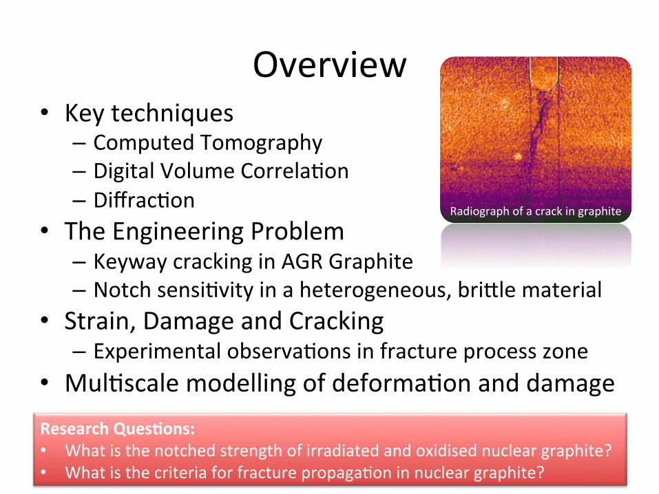
Overview'• Key'techniques'– Computed'Tomography'– Digital'Volume'Correla=on'– Diffrac=on'
• The'Engineering'Problem'– Keyway'cracking'in'AGR'Graphite'– Notch'sensi=vity'in'a'heterogeneous,'bri4le'material'
• Strain,'Damage'and'Cracking''– Experimental'observa=ons'in'fracture'process'zone''
• Mul=scale'modelling'of'deforma=on'and'damage'
2'
Research(Ques+ons:((• What'is'the'notched'strength'of'irradiated'and'oxidised'nuclear'graphite?'• What'is'the'criteria'for'fracture'propaga=on'in'nuclear'graphite?'-
Radiograph'of'a'crack'in'graphite'
COMBINED(TOMOGRAPHY(AND(DIGITAL(VOLUME(CORRELATION((
Observing'and'Measuring'in'3D'
3'
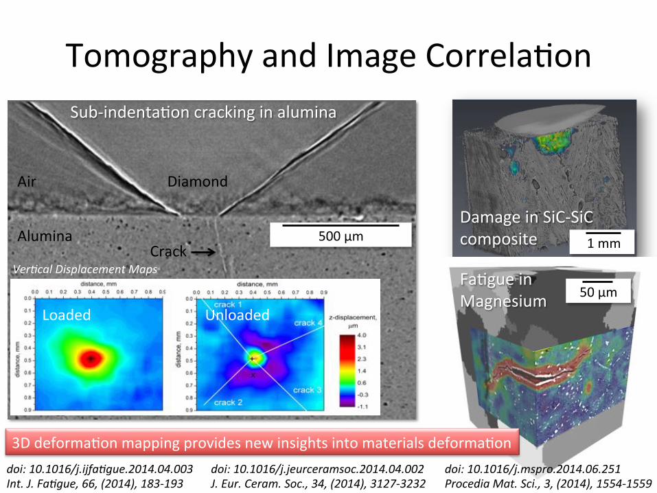
Tomography'and'Image'Correla=on'
4'
Mathematical, Physical and Life Sciences Division
Quasi-Brittle Materials
Studies of Quasi-Brittle Materials by X-ray Tomography and Digital Volume Correlation Mahmoud Mostafavi1, Christina Reinhard2, Robert C. Atwood2 and James Marrow1
1 Oxford University, Department of Materials and Oxford Martin School
2 Diamond Light Source, Beamline I12
The three-dimensional tomography images are analysed by Digital Volume Correlation. This highly sensitive technique measures displacement vectors between successive images. Differentiation of the displacement field produces an effective strain field, which can be used to visualise and quantify the crack opening behaviour as well as the elastic and inelastic strains around the crack. These data validate and tune material-dependent models for damage propagation, such as the cohesive zone model. The models may be used to design miniature test specimens to reliably measure the properties of degraded materials, extracted from engineering components.
Our work aims to understand the interaction between microstructure and damage in quasi-brittle materials, of which nuclear graphite in an example. The techniques are also applicable to feature-rich, heterogeneous brittle materials such as ceramic-matrix composites, thermal barrier coatings and concretes, which are key structural materials in current and next generation nuclear power. Engineers assure the safety of structures containing defects by Structural Integrity Assessment (SIA). For instance, the SIA of nuclear graphite is critical to the continued safe operation of the UK’s Advanced Gas Reactors (AGR). Radiolytic oxidation degrades its strength (amongst other properties), while neutron irradiation causes dimensional change, which develops tensile stress at critical locations. Ultimately, this would cause the moderator bricks in the reactor core to fracture; this is a major limit to reactor lifetime as they also act as channels for fuel and control rods. Confidence in graphite integrity is a major challenge to AGR lifetime extension and over-conservative assessments that end the lifetime prematurely will be detrimental to the UK economy. Detailed observations of fracture processes, using three-dimensional characterisation techniques, are being used in our work to validate models for the effects of microstructure degradation on fracture behaviour in nuclear materials.
Ceramic matrix composites (e.g. Silicon Carbide – Silicon Carbide fibre) are candidate materials for the fuel clad of some Generation IV nuclear fission reactors and also for the tritium breeding components in nuclear fusion power. Their high temperature structural properties are critical for safe operation; tolerance is needed to fast neutron irradiation that may cause damage to fibre-matrix interfaces and swelling. Techniques are needed that can study damage, in situ and at elevated temperatures. Initial studies at room temperature show that deformation within the material can be mapped by digital volume correlation of high resolution tomographic images. Future work will investigate elevated temperature deformation and the relation between damage and microstructure. 1 mm
Awards of X-ray beam time at the Diamond Light Source (JEEP I12) are gratefully acknowledged (Experiments EE7119 & EE7730).
Wedge-loading of the short chevron-notch specimen
Digital volume correlation to measure the relative crack opening displacements between two successive tomography scans. Image slices in the plane orthogonal to the Z-axis are shown; left - prior to loading (no crack) and right - under load (cracked).
0
-1
-2
-3
-4
-5
-6
Log(ε1)
3 mm
Visualisation of deformation caused by Hertzian indentation of a SiC-SiCfibre composite
Displacements measured beneath the Hertzian indentation by digital volume correlation of the tomography data. The maximum principal strains from the displacement field are also shown, and are compared with finite element simulation (left).
The propagated crack within the chevron-notch specimen (crack opening displacement visualised as nominal opening strain). The crack has diverted around a strong “filler” particle.
Crack opening displacement (along middle of the crack), compared with linear elastic and cohesive zone models. The measured opening ahead of the elastic crack tip is due to damage in the fracture process zone.
Selected Publications: Observation and quantification of three-dimensional crack propagation in poly-granular graphite, , M. Mostafavi, S.A. McDonald, P.M. Mummery, T.J. Marrow Engineering Fracture Mechanics 2013 Flexural strength and defect behaviour of polygranular graphite under different states of stress, M. Mostafavi, S.A. McDonald, H. Çetinel, P.M. Mummery, T.J. Marrow Carbon 2013
Sample diameter: 25 mm
Contact details: Prof. James Marrow
Tel.: +44 (0)1865 273938
E-Mail: [email protected]
Website: oxford.academia.edu/JamesMarrow
500'µm'
Loaded' Unloaded'
Sub:indenta=on'cracking'in'alumina'
50'µm'
'1'mm'
Damage'in'SiC:SiC'composite'
Fa=gue'in'Magnesium'
3D'deforma=on'mapping'provides'new'insights'into'materials'deforma=on'doi:-10.1016/j.ijfa*gue.2014.04.003-Int.-J.-Fa*gue,-66,-(2014),-183<193-
doi:-10.1016/j.mspro.2014.06.251-Procedia-Mat.-Sci.,-3,-(2014),-1554<1559-
doi:-10.1016/j.jeurceramsoc.2014.04.002-J.-Eur.-Ceram.-Soc.,-34,-(2014),-3127<3232-
Ver*cal-Displacement-Maps-
Diamond'Air'
Alumina'Crack'
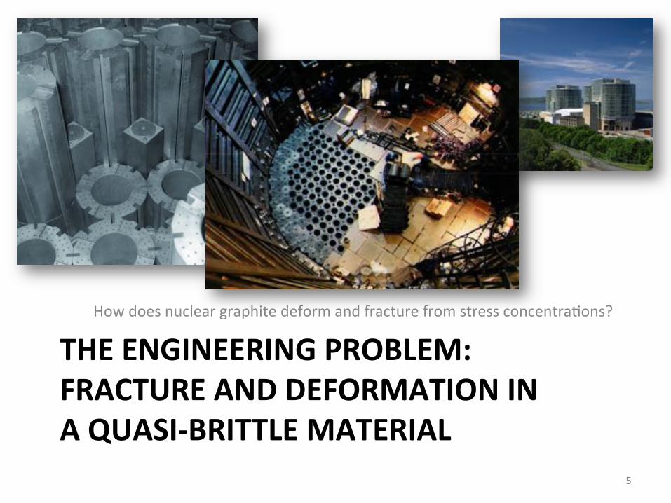
THE(ENGINEERING(PROBLEM:(FRACTURE(AND(DEFORMATION(IN(A(QUASIBBRITTLE(MATERIAL(
How'does'nuclear'graphite'deform'and'fracture'from'stress'concentra=ons?'
5'
174
Figure 5:25 Examples of filler particle porosity.
5.2 Evaluation of Young’s modulus in virgin Gilsocarbon IM1-24 Accurate measurement of Young’s modulus represents an essential precursor to
determining fracture properties in elastic media using the techniques prescribed
by both ASTM E1820 and BS7448 Pt4. The most common method for
measuring static Young’s modulus is to load tensile test specimens below the
elastic limit using an extensometer, or strain gauge, to measure the
displacements throughout the test.
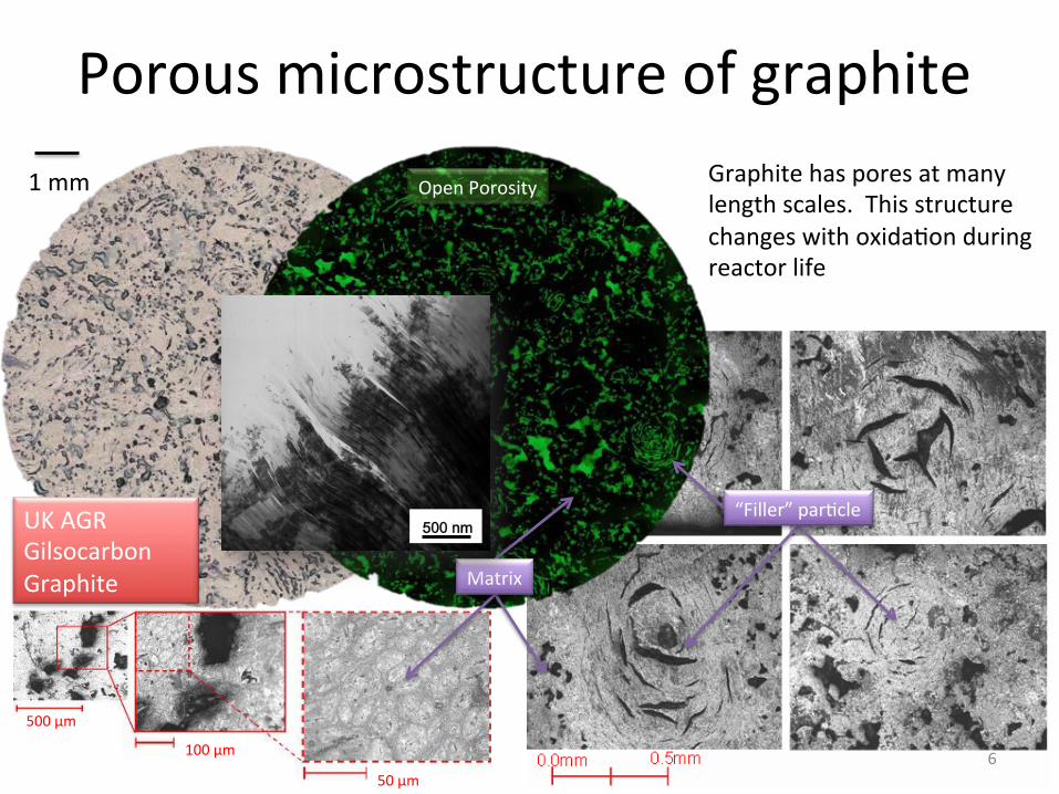
Porous'microstructure'of'graphite'
6'
1'mm' Graphite'has'pores'at'many'length'scales.''This'structure'changes'with'oxida=on'during'reactor'life'
158
few microns distributed, apparently at random, throughout the structure (Figure
5:13). The grains observed in this image are likely to consist of both the flour
and the binder[97]; the regions between them are commonly referred to as flour.
This is fine graphite powder that forms the interface between the grains. Far
higher resolution is needed to study the matrix in any significant manner.
Figure 5:13 Progressive magnification of a surface of a graphite specimen to highlight a region within the binder that contains unconnected particles (Mosaics).
50µm
A B
50µm
A B
Figure 5:14 Optical microscopy of the matrix. A region within the binder where the
orientation of the Basal planes extends to approx 50µm is shown in ‘A’. Highlighted in ‘B’ are some of the smallest binder particles, measuring only a few microns in length. The latter forms a mosaic region as defined above. Both of these images are from a specimen of Gilsocarbon graphite.
500'µm'
100'µm'
50'µm'
UK'AGR'Gilsocarbon'Graphite' Matrix'
“Filler”'par=cle'
Open'Porosity' 11
����QP ����QP
a
Fig. 2
100 nm
H
b
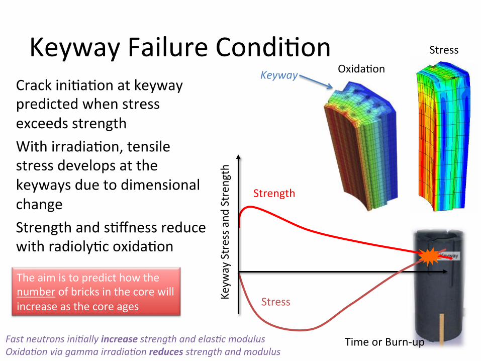
Keyway'Failure'Condi=on'Crack'ini=a=on'at'keyway'predicted'when'stress'exceeds'strength'With'irradia=on,'tensile'stress'develops'at'the'keyways'due'to'dimensional'change'Strength'and's=ffness'reduce'with'radioly=c'oxida=on'
Time'or'Burn:up'
Keyw
ay'Stress'a
nd'Stren
gth'
Strength'
Stress'
Oxida=on'Stress'
The'aim'is'to'predict'how'the'number'of'bricks'in'the'core'will'increase'as'the'core'ages'
Keyway-
Fast-neutrons-ini*ally-increase-strength-and-elas*c-modulus-Oxida*on-via-gamma-irradia*on-reduces-strength-and-modulus-

Graphite'Property'Measurement'
8'
Trepanning'Tool'
The'effects'of'irradia=on'and'oxida=on'are'measured'using'small'test'specimens,'cut'from'trepanned'cores'
Trepanning'Tool'
10 10
•Large variability in irradiated graphite properties due to: •variability in manufactured graphite •operating conditions (dose, temperature, oxidation)
•Measurements have to be done on very small samples: •because there is a size limitation on the material that can be trepanned from the reactor •because there is a large density gradient in a trepanned sample •in order to obtain as much information as possible on each trepanned sample
Challenges in measuring irradiated graphite
Trepanned'Core'Sample'(NNL)'
~20'mm'
~6'x'6'mm'
Flexural'strength'specimen'
26'cm'
Trepanning'Instrument'
keyway'
9'
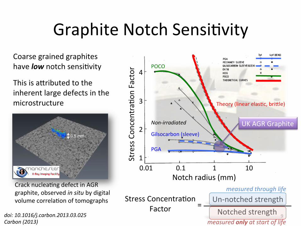
Graphite'Notch'Sensi=vity'
Notch'radius'(mm)'
Stress'Con
centra=o
n'Factor'
Coarse'grained'graphites'have'low'notch'sensi=vity'
€
PGA'
Gilsocarbon'(sleeve)'
POCO'
Theory'(linear'elas=c,'bri4le)'
This'is'a4ributed'to'the'inherent'large'defects'in'the'microstructure'
Crack'nuclea=ng'defect'in'AGR'graphite,'observed'in-situ'by'digital'volume'correla=on'of'tomographs'
UK'AGR'Graphite'
0.01' 0.1' 1' 10'1'
2'
4'
3'
Non<irradiated-
Stress'Concentra=on'Factor'
Un:notched'strength''Notched'strength''
='
measured-through-life---
measured-only-at-start-of-life---doi:-10.1016/j.carbon.2013.03.025-Carbon-(2013)-

Graphite'Notch'Sensi=vity'
10'
Distance'
Stress'
Linear'elas=c'
Non:irradiated'graphite'
Irradiated-graphite?-
Inelas*c-or-nonlinear-elas*c-behaviour-may-affect-notch-sensi*vity,-par*cularly-in-small-specimens-
Can-a-“small-specimen-test”-measure-the-notch-sensi*vity-in-irradiated-graphite-to-sufficiently-describe-large-component-behaviour?-
We'need'to'measure'the'notch'stress/strain'field'to'validate'damage'models'
In-metals,-size-effects-are-due-to-inelas*c-behaviour-in-fracture-process-zone-(i.e.-plas*c-zone)-that-affects-constraint-
What(is(the(Notch(Sensi+vity(of(Irradiated(Graphite?(
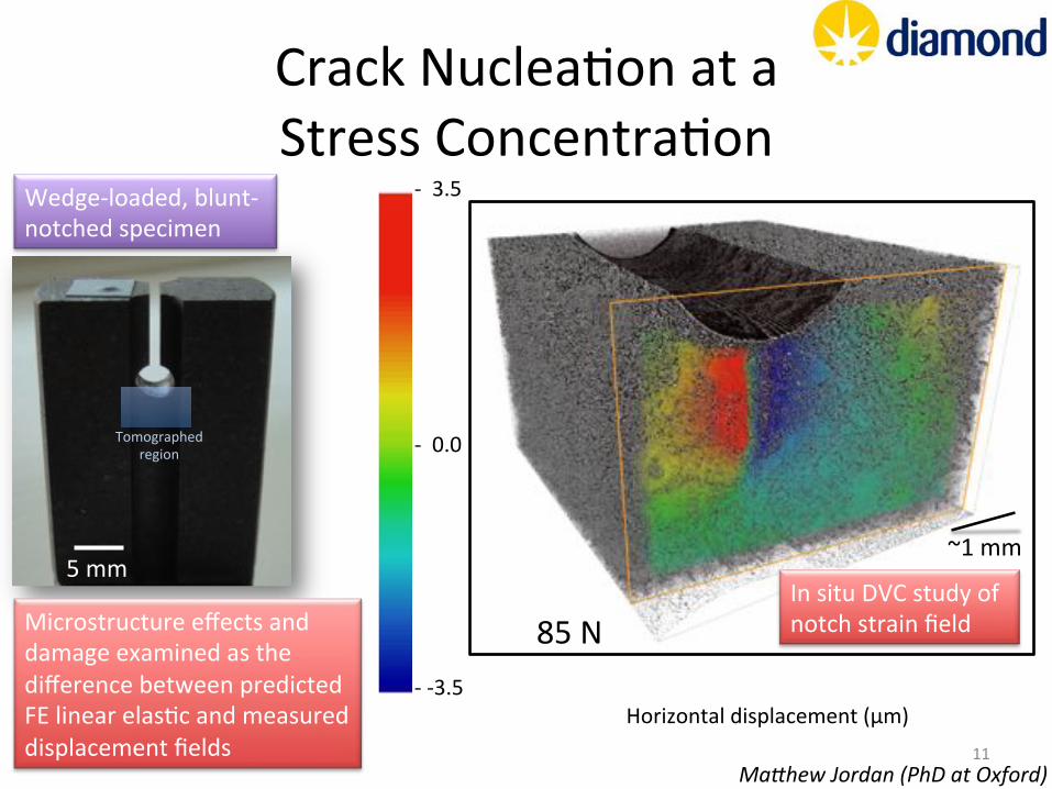
Crack'Nuclea=on'at'a'Stress'Concentra=on'
11'
6'mm'
5'mm'
Microstructure'effects'and'damage'examined'as'the'difference'between'predicted'FE'linear'elas=c'and'measured'displacement'fields''
Tomographed'region'
Wedge:loaded,'blunt:notched'specimen'
50'N'75'N'85'N'
Horizontal'displacement'(µm)'
:''3.5'
:':3.5'
:''0.0'
In'situ'DVC'study'of'notch'strain'field'
Mabhew-Jordan-(PhD-at-Oxford)-
~1'mm'
GRAPHITE(DEFORMATION(
12'
An'examina=on'of'strain'during'tensile'deforma=on'

X:ray'Strain'Mapping'on'I12'(JEEP)'
13'
XBray(Beam((80(ke
V)( 250'cm'
42'cm'
Diffrac=on'Image'Plate'
Loading'Rig'
Radiography'Camera'and'
Op=cs'
Specimen'
:1000'
:500'
0'
500'
1000'
:500' 0' 500' 1000'1500'2000'2500'
Tran
sverse(Bulk(Strain((µε)(
Tensile(Bulk(Strain((µε)(
14'
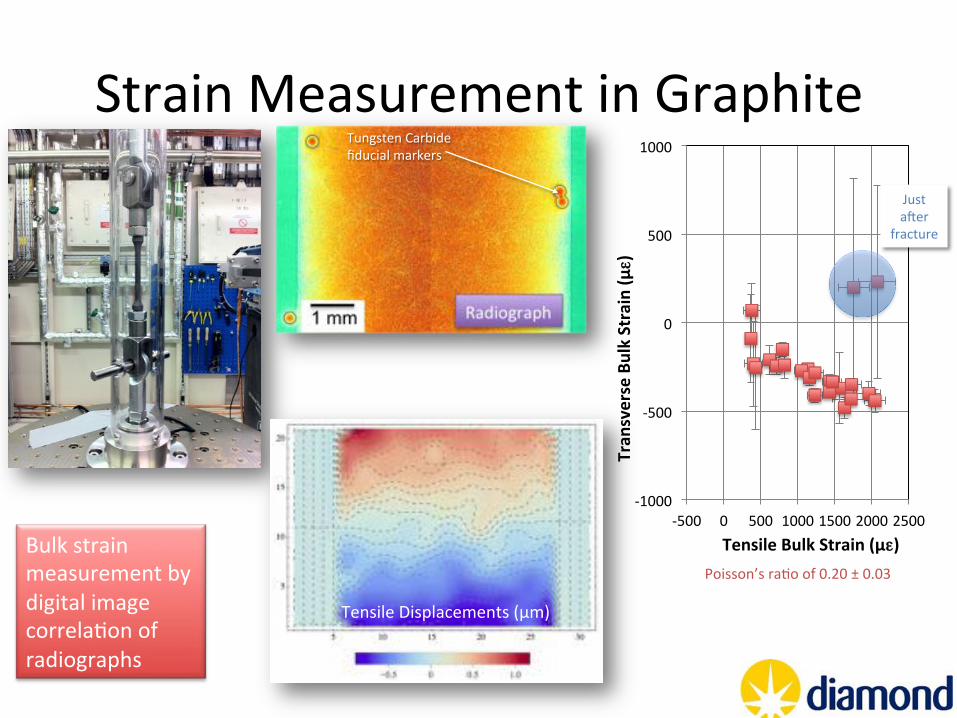
Strain'Measurement'in'Graphite'Vy Vx
Raw
dat
aC
orre
cted
Load 450N: step 4
Tensile'Displacements'(µm)'
Bulk'strain'measurement'by'digital'image'correla=on'of'radiographs''
Just'aner'
fracture'
Tungsten'Carbide'fiducial'markers'
Poisson’s'ra=o'of'0.20'±'0.03'
15'
Strain'Measurement'in'Graphite'
0"
1000"
2000"
3000"
4000"
5000"
6000"
7000"
8000"
0" 500" 1000" 1500" 2000" 2500" 3000"
Intensity
((32b
its)(
Posi0on(in(profile((pixels)(
(002)'
(100)'(101)'(102)'
Intensity
'(rela=
ve)'
Posi=on'(Pixels)'
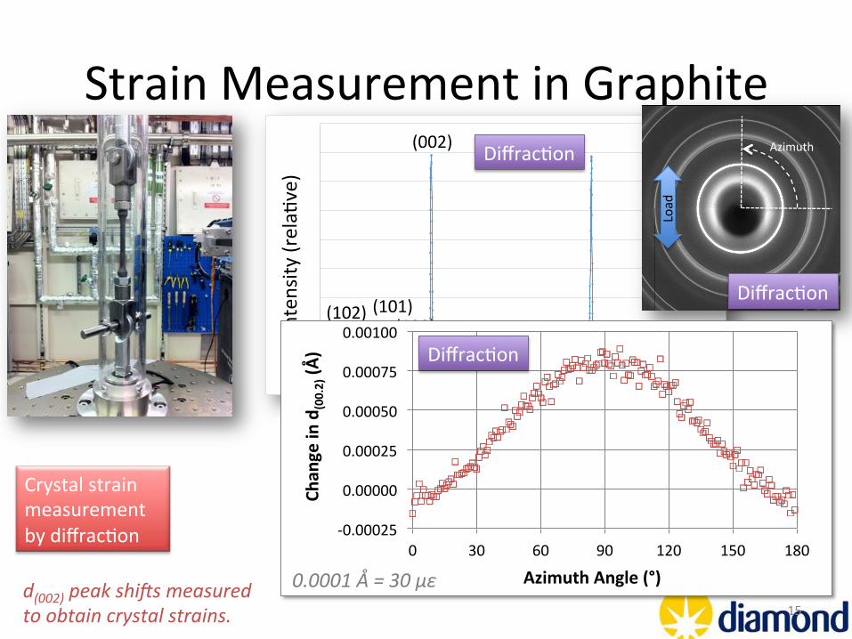
Diffrac=on'
d(002)-peak-shics-measured-to-obtain-crystal-strains.-
Diffrac=on'
Azimuth'
Load'
Crystal'strain'measurement'by'diffrac=on' :0.00025'
0.00000'
0.00025'
0.00050'
0.00075'
0.00100'
0' 30' 60' 90' 120' 150' 180'
Chan
ge(in(d
(00.2)((Å
)(
Azimuth(Angle((°)(
Diffrac=on'
0.0001-Å-=-30-µε-
Strain'Measurement'in'Graphite'
16'
!0.0005%
0.0000%
0.0005%
0.0010%
!1000% 0% 1000% 2000% 3000%
Chan
ge'in'd
(0002)'(Å
)'
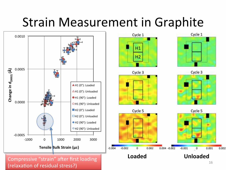
Tensile'Bulk'Strain'(µε)'
H1%(0°):%Loaded%
H1%(0°):%Unloaded%
H1%(90°):%Loaded%
H1%(90°):%Unloaded%
H2%(0°):%Loaded%
H2%(0°):%Unloaded%
H2%(90°):%Loaded%
H2%(90°):%Unloaded%
Compressive'“strain”'aner'first'loading'(relaxa=on'of'residual'stress?)'
H1'
H2'
Loaded( Unloaded(
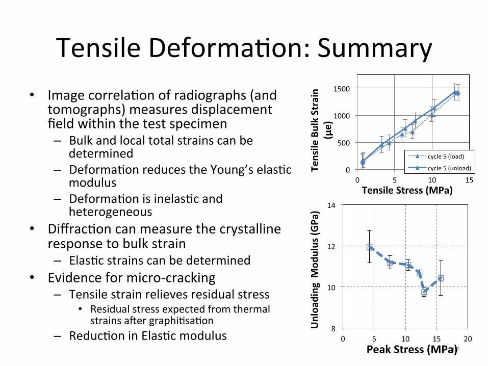
Tensile'Deforma=on:'Summary'• Image'correla=on'of'radiographs'(and'
tomographs)'measures'displacement'field'within'the'test'specimen'– Bulk'and'local'total'strains'can'be'
determined'– Deforma=on'reduces'the'Young’s'elas=c'
modulus'– Deforma=on'is'inelas=c'and'
heterogeneous'• Diffrac=on'can'measure'the'crystalline'
response'to'bulk'strain'– Elas=c'strains'can'be'determined'
• Evidence'for'micro:cracking''– Tensile'strain'relieves'residual'stress'
• Residual'stress'expected'from'thermal'strains'aner'graphi=sa=on'
– Reduc=on'in'Elas=c'modulus'17'
8'
10'
12'
14'
0' 5' 10' 15' 20'
Unloa
ding((M
odulus((G
Pa)((
Peak(Stress((MPa)(
0'
500'
1000'
1500'
0' 5' 10' 15'
Tensile(Bulk(Strain(
(µe)(
Tensile(Stress((MPa)(
cycle'5'(load)'
cycle'5'(unload)'
CRACK(PROPAGATION(An'examina=on'of'crack'strain'fields'
18'
Crack%Propaga>on%
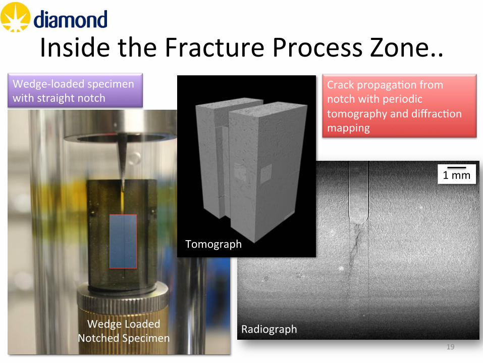
Wedge'Loaded'Notched'Specimen'
Radiograph'
1'mm'
Inside'the'Fracture'Process'Zone..'
19'
Crack%Propaga>on%
Tomograph'
Crack'propaga=on'from'notch'with'periodic'tomography'and'diffrac=on'mapping'
Wedge:loaded'specimen'with'straight'notch'
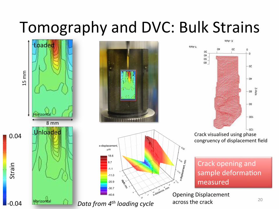
Tomography'and'DVC:'Bulk'Strains'
Data-from-4th-loading-cycle-
Crack%Propaga>on% Cycle%4%(example)%strain x DVC
inc d0 at 0º
Loaded
strain x DVC
inc d0 at 0º
Unloaded
strain x DVC
inc d0 at 0º
Loaded
strain x DVC
inc d0 at 0º
Unloaded
strain z DVC
inc d0 at 90º
Loaded
strain z DVC
inc d0 at 90º
Unloaded
strain z DVC
inc d0 at 90º
Loaded
strain z DVC
inc d0 at 90º
Unloaded
strain x DVC
inc d0 at 0º
Loaded
strain x DVC
inc d0 at 0º
Unloaded
strain x DVC
inc d0 at 0º
Loaded
strain x DVC
inc d0 at 0º
Unloaded
strain z DVC
inc d0 at 90º
Loaded
strain z DVC
inc d0 at 90º
Unloaded
strain z DVC
inc d0 at 90º
Loaded
strain z DVC
inc d0 at 90º
Unloaded
Loaded% Unloaded%
Bulk%
Crystal%
Ver>cal%Horizontal% Ver>cal%Horizontal%strain x DVC
inc d0 at 0º
Loaded
strain x DVC
inc d0 at 0º
Unloaded
strain x DVC
inc d0 at 0º
Loaded
strain x DVC
inc d0 at 0º
Unloaded
0.04%
40.04%
0.0004%
40.0004%
Cycle%4%(example)%strain x DVC
inc d0 at 0º
Loaded
strain x DVC
inc d0 at 0º
Unloaded
strain x DVC
inc d0 at 0º
Loaded
strain x DVC
inc d0 at 0º
Unloaded
strain z DVC
inc d0 at 90º
Loaded
strain z DVC
inc d0 at 90º
Unloaded
strain z DVC
inc d0 at 90º
Loaded
strain z DVC
inc d0 at 90º
Unloaded
strain x DVC
inc d0 at 0º
Loaded
strain x DVC
inc d0 at 0º
Unloaded
strain x DVC
inc d0 at 0º
Loaded
strain x DVC
inc d0 at 0º
Unloaded
strain z DVC
inc d0 at 90º
Loaded
strain z DVC
inc d0 at 90º
Unloaded
strain z DVC
inc d0 at 90º
Loaded
strain z DVC
inc d0 at 90º
Unloaded
Loaded% Unloaded%
Bulk%
Crystal%
Ver>cal%Horizontal% Ver>cal%Horizontal%strain x DVC
inc d0 at 0º
Loaded
strain x DVC
inc d0 at 0º
Unloaded
strain x DVC
inc d0 at 0º
Loaded
strain x DVC
inc d0 at 0º
Unloaded
0.04%
40.04%
0.0004%
40.0004%
Horizontal'
Horizontal'
15'm
m'
8'mm'
Unloaded'
Loaded'
Opening'Displacement'across'the'crack' 20'
Crack'opening'and'sample'deforma=on'measured''
Strain'
Cycle%4%(example)%strain x DVC
inc d0 at 0º
Loaded
strain x DVC
inc d0 at 0º
Unloaded
strain x DVC
inc d0 at 0º
Loaded
strain x DVC
inc d0 at 0º
Unloaded
strain z DVC
inc d0 at 90º
Loaded
strain z DVC
inc d0 at 90º
Unloaded
strain z DVC
inc d0 at 90º
Loaded
strain z DVC
inc d0 at 90º
Unloaded
strain x DVC
inc d0 at 0º
Loaded
strain x DVC
inc d0 at 0º
Unloaded
strain x DVC
inc d0 at 0º
Loaded
strain x DVC
inc d0 at 0º
Unloaded
strain z DVC
inc d0 at 90º
Loaded
strain z DVC
inc d0 at 90º
Unloaded
strain z DVC
inc d0 at 90º
Loaded
strain z DVC
inc d0 at 90º
Unloaded
Loaded% Unloaded%
Bulk%
Crystal%
Ver>cal%Horizontal% Ver>cal%Horizontal%strain x DVC
inc d0 at 0º
Loaded
strain x DVC
inc d0 at 0º
Unloaded
strain x DVC
inc d0 at 0º
Loaded
strain x DVC
inc d0 at 0º
Unloaded
0.04%
40.04%
0.0004%
40.0004%
0.04'
:0.04'
Reference dataset: Tomo 4 (#28990)
Deformed dataset: Tomo 7 (#29024)
Volume size: 6.48 x 3.96 x 4.68 mm (3600x2200x2600 pixels)
DaVis parameters:
256 × 256 × 256 voxel interrogation window, with 50% overlap and 2 passes, followed by a 128 × 128 × 128 interrogation window, with 75% overlap and 3 passes
Output displacement matrix size: 112x69x81 voxels
Crack opening displacement (notch area was removed at z=0.52 mm, average COD-value and errors were calculated across all y-coordinates):
0
1
2
3
4
5
6
4
3
2
1
0
-0 .04
-0.02
0.00
0.02x-displacement,
Pm
depth, mm
x-dis
place
men
t, m
m
x-distance, mm
-40.6
-30.7
-20.9
-11.0
-1.1
8.7
18.6
0 1 2 3 4 5
0.01
0.02
0.03
0.04
0.05
0.06
0.07
CO
D, m
m
crack length, mm
4
3
2
1
00 1 2 3 4 5 6
x-displacement, Pm
XZ-plane, y=middle
dept
h, m
m
-40.0
-29.2
-18.3
-7.5
3.3
14.2
25.0
z=0.52 mm
Crack'visualised'using'phase'congruency'of'displacement'field'

Diffrac=on:'Crystal'Strains'
21'
Cycle%4%(example)%strain x DVC
inc d0 at 0º
Loaded
strain x DVC
inc d0 at 0º
Unloaded
strain x DVC
inc d0 at 0º
Loaded
strain x DVC
inc d0 at 0º
Unloaded
strain z DVC
inc d0 at 90º
Loaded
strain z DVC
inc d0 at 90º
Unloaded
strain z DVC
inc d0 at 90º
Loaded
strain z DVC
inc d0 at 90º
Unloaded
strain x DVC
inc d0 at 0º
Loaded
strain x DVC
inc d0 at 0º
Unloaded
strain x DVC
inc d0 at 0º
Loaded
strain x DVC
inc d0 at 0º
Unloaded
strain z DVC
inc d0 at 90º
Loaded
strain z DVC
inc d0 at 90º
Unloaded
strain z DVC
inc d0 at 90º
Loaded
strain z DVC
inc d0 at 90º
Unloaded
Loaded% Unloaded%
Bulk%
Crystal%
Ver>cal%Horizontal% Ver>cal%Horizontal%strain x DVC
inc d0 at 0º
Loaded
strain x DVC
inc d0 at 0º
Unloaded
strain x DVC
inc d0 at 0º
Loaded
strain x DVC
inc d0 at 0º
Unloaded
0.04%
40.04%
0.0004%
40.0004%
Cycle%4%(example)%strain x DVC
inc d0 at 0º
Loaded
strain x DVC
inc d0 at 0º
Unloaded
strain x DVC
inc d0 at 0º
Loaded
strain x DVC
inc d0 at 0º
Unloaded
strain z DVC
inc d0 at 90º
Loaded
strain z DVC
inc d0 at 90º
Unloaded
strain z DVC
inc d0 at 90º
Loaded
strain z DVC
inc d0 at 90º
Unloaded
strain x DVC
inc d0 at 0º
Loaded
strain x DVC
inc d0 at 0º
Unloaded
strain x DVC
inc d0 at 0º
Loaded
strain x DVC
inc d0 at 0º
Unloaded
strain z DVC
inc d0 at 90º
Loaded
strain z DVC
inc d0 at 90º
Unloaded
strain z DVC
inc d0 at 90º
Loaded
strain z DVC
inc d0 at 90º
Unloaded
Loaded% Unloaded%
Bulk%
Crystal%
Ver>cal%Horizontal% Ver>cal%Horizontal%strain x DVC
inc d0 at 0º
Loaded
strain x DVC
inc d0 at 0º
Unloaded
strain x DVC
inc d0 at 0º
Loaded
strain x DVC
inc d0 at 0º
Unloaded
0.04%
40.04%
0.0004%
40.0004%Data-from-4th-loading-cycle-
Crack%Propaga>on%
Horizontal'
Horizontal'
19'm
m'
10'mm'
Strain'
0.0004'
:0.0004'
Unloaded'
Loaded'
Horizontal%Strains%
Bulk%
Bulk%
Crystal%
Crystal%
strain x DVC
inc d0 at 0º
Loaded
strain x DVC
inc d0 at 0º
Unloaded
Horizontal%Strains%
Bulk%
Bulk%
Crystal%
Crystal%
strain x DVC
inc d0 at 0º
Loaded
strain x DVC
inc d0 at 0º
Unloaded
Horizontal%Strains%
Bulk%
Bulk%
Crystal%
Crystal%
strain x DVC
inc d0 at 0º
Loaded
strain x DVC
inc d0 at 0º
Unloaded
Horizontal%Strains%
Bulk%
Bulk%
Crystal%
Crystal%
strain x DVC
inc d0 at 0º
Loaded
strain x DVC
inc d0 at 0º
Unloaded
Horizontal%Strains%
Bulk%
Bulk%
Crystal%
Crystal%
strain x DVC
inc d0 at 0º
Loaded
strain x DVC
inc d0 at 0º
Unloaded1' 2' 3' 4' 5'
Strain'field'of'a'propaga=ng'crack'measured'(2D)'Cycle%4%(example)%
strain x DVC
inc d0 at 0º
Loaded
strain x DVC
inc d0 at 0º
Unloaded
strain x DVC
inc d0 at 0º
Loaded
strain x DVC
inc d0 at 0º
Unloaded
strain z DVC
inc d0 at 90º
Loaded
strain z DVC
inc d0 at 90º
Unloaded
strain z DVC
inc d0 at 90º
Loaded
strain z DVC
inc d0 at 90º
Unloaded
strain x DVC
inc d0 at 0º
Loaded
strain x DVC
inc d0 at 0º
Unloaded
strain x DVC
inc d0 at 0º
Loaded
strain x DVC
inc d0 at 0º
Unloaded
strain z DVC
inc d0 at 90º
Loaded
strain z DVC
inc d0 at 90º
Unloaded
strain z DVC
inc d0 at 90º
Loaded
strain z DVC
inc d0 at 90º
Unloaded
Loaded% Unloaded%
Bulk%
Crystal%
Ver>cal%Horizontal% Ver>cal%Horizontal%strain x DVC
inc d0 at 0º
Loaded
strain x DVC
inc d0 at 0º
Unloaded
strain x DVC
inc d0 at 0º
Loaded
strain x DVC
inc d0 at 0º
Unloaded
0.04%
40.04%
0.0004%
40.0004%
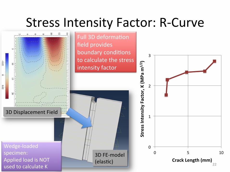
Stress'Intensity'Factor:'R:Curve'
22'
0'
1'
2'
3'
0' 5' 10'
Stress(In
tensity
(Factor,(K((M
Pa(m
1/2 )(
Crack(Length((mm)(
Full'3D'deforma=on'field'provides'boundary'condi=ons'to'calculate'the'stress'intensity'factor'
3D'FE:model'(elas=c)'
3D'Displacement'Field'
Wedge:loaded'specimen:'Applied'load'is'NOT'used'to'calculate'K'
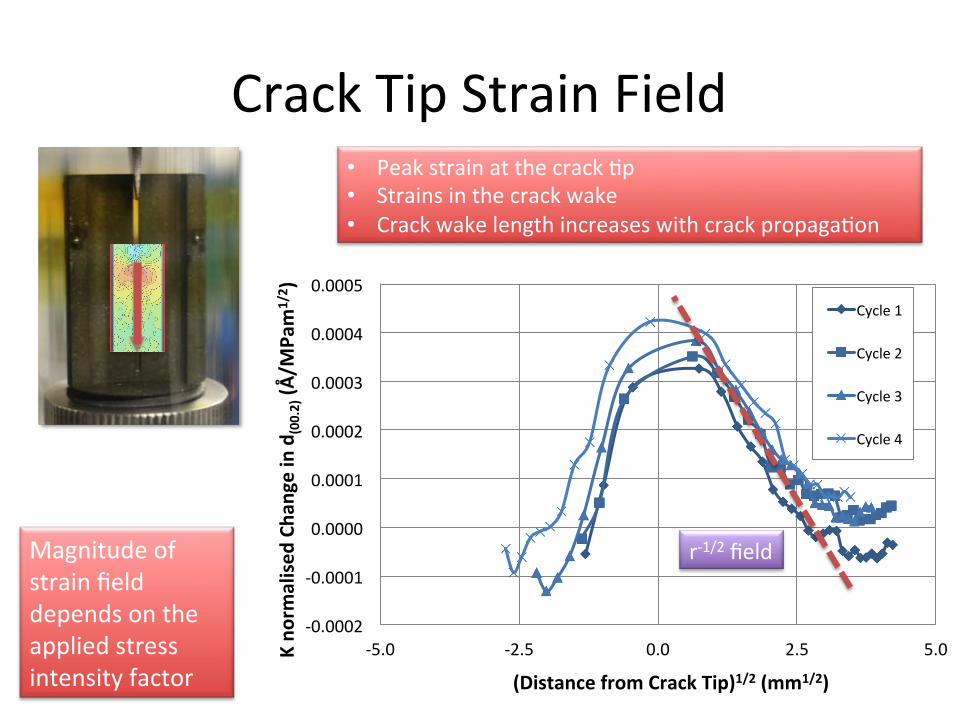
Crack'Tip'Strain'Field'
23'
Crack%Propaga>on%
:0.001'
0.000'
0.001'
0.002'
0' 5' 10' 15' 20'
Chan
ge(in(d
(00.2)((Å
)(
Distance((mm)(
Cycle'1'
Cycle'2'
Cycle'3'
Cycle'4'
Maximum-change-in-d(00.2)-measured-in-tensile-test-
:0.001'
0.000'
0.001'
0.002'
0' 5' 10' 15' 20'K(no
rmalised
(Cha
nge(in(d
(00.2)((Å
/MPa
m1/2 )(
Distance((mm)(
Cycle'1'
Cycle'2'
Cycle'3'
Cycle'4'
Normalised'by'applied'stress'intensity'factor'
Crack'=p'posi=ons'
Notch'
:0.0002'
:0.0001'
0.0000'
0.0001'
0.0002'
0.0003'
0.0004'
0.0005'
:10' 0' 10' 20'K(no
rmalised
(Cha
nge(in(d
(00.2)((Å
/MPa
m1/2 )(
Distance(from(Crack(Tip((mm)(
Cycle'1'
Cycle'2'
Cycle'3'
Cycle'4'
Rela=ve'to'crack'=p'
Magnitude'of'strain'field'depends'on'the'applied'stress'intensity'factor'
:0.0002'
:0.0001'
0.0000'
0.0001'
0.0002'
0.0003'
0.0004'
0.0005'
:5.0' :2.5' 0.0' 2.5' 5.0'K(no
rmalised
(Cha
nge(in(d
(00.2)((Å
/MPa
m1/2 )(
(Distance(from(Crack(Tip)1/2((mm1/2)(
Cycle'1'
Cycle'2'
Cycle'3'
Cycle'4'
• Peak'strain'at'the'crack'=p'• Strains'in'the'crack'wake'• Crack'wake'length'increases'with'crack'propaga=on'
r:1/2'field'
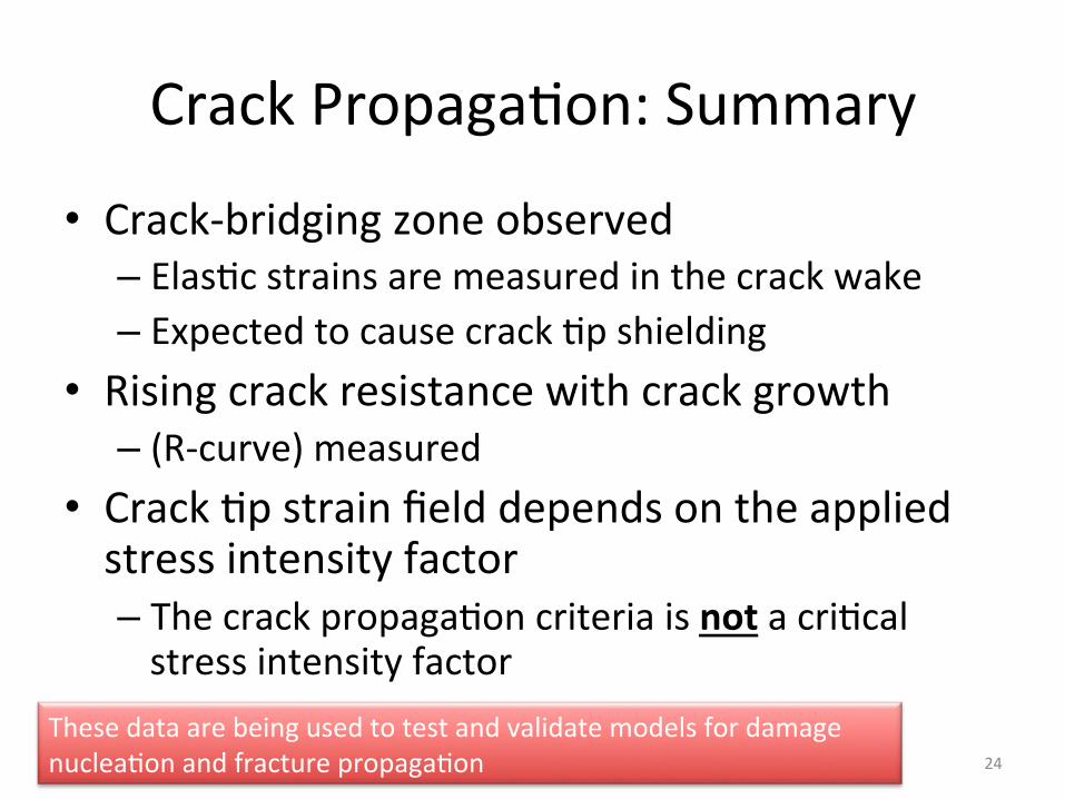
Crack'Propaga=on:'Summary'
• Crack:bridging'zone'observed'– Elas=c'strains'are'measured'in'the'crack'wake'– Expected'to'cause'crack'=p'shielding'
• Rising'crack'resistance'with'crack'growth'– (R:curve)'measured'
• Crack'=p'strain'field'depends'on'the'applied'stress'intensity'factor'– The'crack'propaga=on'criteria'is'not'a'cri=cal'stress'intensity'factor'
24'
These'data'are'being'used'to'test'and'validate'models'for'damage'nuclea=on'and'fracture'propaga=on'

Concluding'Comments'• Non<irradiated'graphite'deforma=on'is'accompanied'by'microcracking'– Techniques'developed'to'measure'deforma=on'and'strains'in'small'test'specimens'
– Used'to'validate'models'to'simulate'behaviour'of'engineering'components'
• Effects'of'distributed'cracking'on'notch'sensi=vity'and'size'effects'are'being'examined'
25'
Deforma=on'and'notch'sensi=vity'in'irradiated'graphite'could'be'examined'and'is-being-simulated'to'es=mate'size'effects'

Acknowledgements'
26'
Mathew-Jordan,-Ahmet-Cinar-Alan-Steer,-David-Nowell-
Dr(James(Mar+n'(1933<2013)-Founder'of'the'Oxford'Mar=n'School'
Experiments:-EE7119,-EE8519,-EE9036,-EE9478-
MICROSTRUCTUREBBASED(DAMAGE(MODEL(
Mul=:scale'modeling'of'damage'development'and'crack'propaga=on'
27'
28'
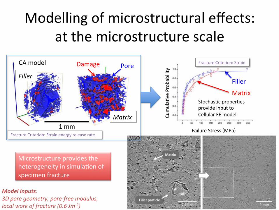
Filler-Pore'Damage'
Matrix-1'mm'
CA'model'
Fracture'Criterion:'Strain'energy'release'rate'Failure'Stress'(MPa)'
Cumula=
ve'Probability'
Filler'
Matrix'Stochas=c'proper=es'provide'input'to'Cellular'FE'model'
Fracture'Criterion:'Strain'
Modelling'of'microstructural'effects:'at'the'microstructure'scale'
Microstructure'provides'the'heterogeneity'in'simula=on'of'specimen'fracture'
Model/inputs:-3D-pore-geometry,-pore<free-modulus,-local-work-of-fracture-(0.6-Jm<2)-
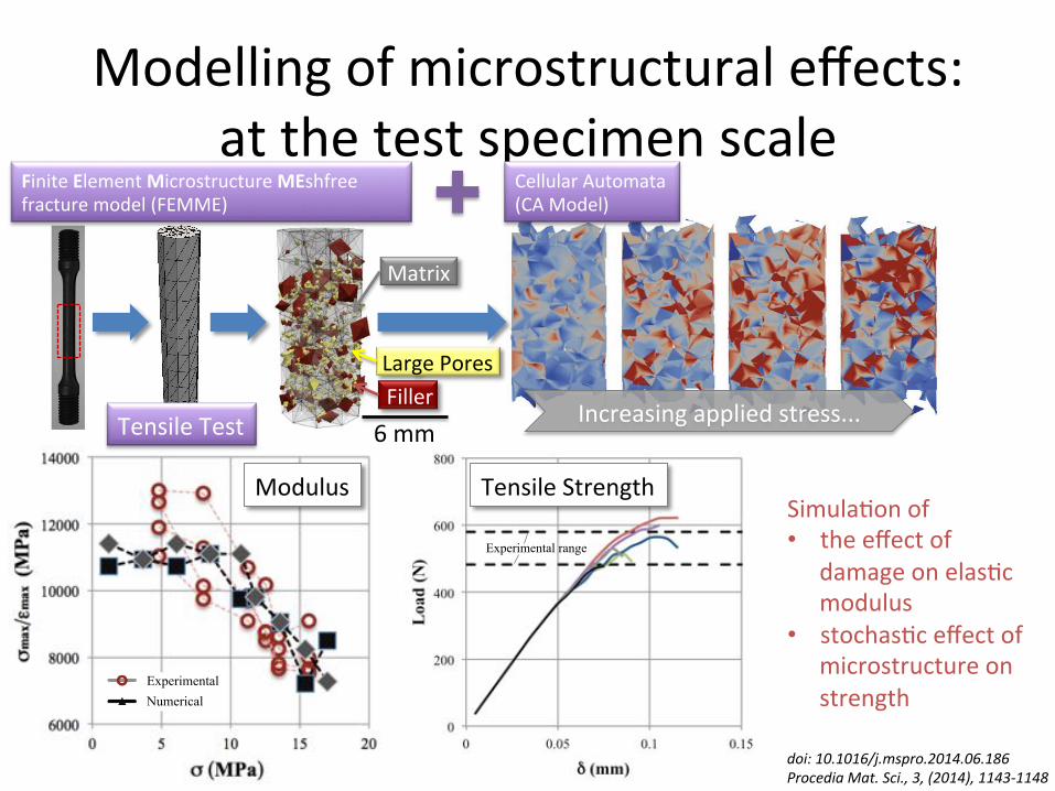
NumericalExperimental
Tensile test, decay of the stiffness
Experimental range
Tensile test, peak load for different microstructures
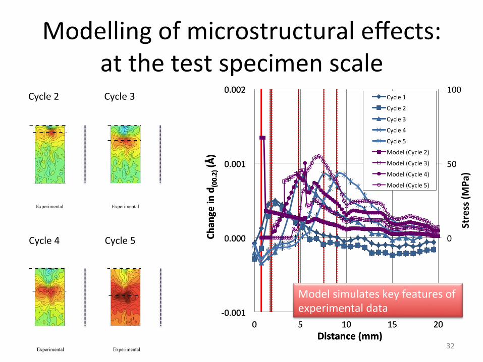
Modelling'of'microstructural'effects:'at'the'test'specimen'scale'
Large'Pores''''Filler''
6'mm'Tensile'Test'
Matrix''
Increasing'applied'stress...'
Simula=on'of'• the'effect'of'
damage'on'elas=c'modulus'
• stochas=c'effect'of'microstructure'on'strength'
Modulus' Tensile'Strength'
doi:-10.1016/j.mspro.2014.06.186-Procedia-Mat.-Sci.,-3,-(2014),-1143<1148-
Finite'Element'Microstructure'MEshfree'fracture'model'(FEMME)''
Cellular'Automata'(CA'Model)'
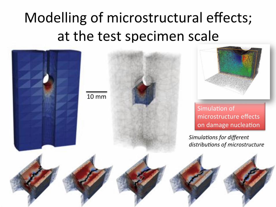
Modelling'of'microstructural'effects;'at'the'test'specimen'scale'
30'
Simula*ons-for-different-distribu*ons-of-microstructure-
Simula=on'of'microstructure'effects'on'damage'nuclea=on'
10'mm'
Modelling'of'microstructural'effects:'at'the'test'specimen'scale'
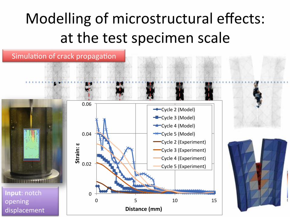
Simula=on'of'crack'propaga=on'
Input:'notch'opening'displacement'
Crack%Propaga>on%
0"
0.02"
0.04"
0.06"
0" 5" 10" 15"
Strain:(ε
Distance((mm)(
Cycle"2"(Model)"Cycle"3"(Model)"Cycle"4"(Model)"Cycle"5"(Model)"Cycle"2"(Experiment)"Cycle"3"(Experiment)"Cycle"4"(Experiment)"Cycle"5"(Experiment)"
Modelling'of'microstructural'effects:'at'the'test'specimen'scale'
strain x DVC
inc d0 at 0º
Loaded
strain x DVC
inc d0 at 0º
Unloaded
strain x DVC
inc d0 at 0º
Loaded
strain x DVC
inc d0 at 0º
Unloaded
strain x DVC
inc d0 at 0º
Loaded
strain x DVC
inc d0 at 0º
Unloaded
strain x DVC
inc d0 at 0º
Loaded
strain x DVC
inc d0 at 0º
Unloaded
Load 2 Load 3 Load 4 Load 5
strain x DVC
inc d0 at 0º
Loaded
strain x DVC
inc d0 at 0º
UnloadedExperimental Numerical Experimental Numerical Experimental Numerical NumericalExperimental
wedge compression test, crack tip position
strain x DVC
inc d0 at 0º
Loaded
strain x DVC
inc d0 at 0º
Unloaded
strain x DVC
inc d0 at 0º
Loaded
strain x DVC
inc d0 at 0º
Unloaded
strain x DVC
inc d0 at 0º
Loaded
strain x DVC
inc d0 at 0º
Unloaded
strain x DVC
inc d0 at 0º
Loaded
strain x DVC
inc d0 at 0º
Unloaded
Load 2 Load 3 Load 4 Load 5
strain x DVC
inc d0 at 0º
Loaded
strain x DVC
inc d0 at 0º
UnloadedExperimental Numerical Experimental Numerical Experimental Numerical NumericalExperimental
wedge compression test, crack tip position
Cycle'2' Cycle'3'
Cycle'4' Cycle'5'
32'
:0.001'
0.000'
0.001'
0.002'
0' 5' 10' 15' 20'
Chan
ge(in(d
(00.2)((Å
)(
Distance((mm)(
Cycle'1'
Cycle'2'
Cycle'3'
Cycle'4'
Cycle'5'
:50'
0'
50'
100'
:0.001'
0.000'
0.001'
0.002'
0' 5' 10' 15' 20'
Stress((M
Pa)(
Chan
ge(in(d
(00.2)((Å
)(
Distance((mm)(
Cycle'1'
Cycle'2'
Cycle'3'
Cycle'4'
Cycle'5'
Model'(Cycle'2)'
Model'(Cycle'3)'
Model'(Cycle'4)'
Model'(Cycle'5)'
Model'simulates'key'features'of'experimental'data'
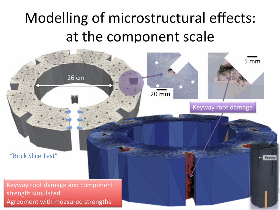
Modelling'of'microstructural'effects:'at'the'component'scale'
“Brick'Slice'Test”'
26'cm'
Keyway'root'damage'
5'mm'
20'mm'
33'
Keyway'root'damage'and'component'strength'simulated'Agreement'with'measured'strengths'
Concluding'Comments'• Microstructure:sensi=ve'modelling'aims'to'predict'the'sensi=vity'of'notch'strength'to'neutron'irradia=on'and'radioly=c'oxida=on'– Porosity'distribu=on'is'measured'– Local'proper=es'of'microstructure'are'simulated'– Global'proper=es'of'component,'and'the'variability'of'strength,'are'simulated'
'• Mul=:scale'modelling'approach'is'being'further'developed'and'validated'by'experiment'
34'

K'field:'1/√r'
35/50'
:0.0002'
:0.0001'
0.0000'
0.0001'
0.0002'
0.0003'
0.0004'
0.0005'
:5.0' :2.5' 0.0' 2.5' 5.0'K(no
rmalised
(Cha
nge(in(d
(00.2)((Å
/MPa
m1/2 )(
(Distance(from(Crack(Tip)1/2((mm1/2)(
Cycle'1'
Cycle'2'
Cycle'3'
Cycle'4'