Stochastic solutions of Navier-Stokes equations: An experimental evidence
7
Stochastic solutions of Navier–Stokes equations: An experimental evidence Ivan Djurek, 1,a Danijel Djurek, 2 and Antonio Petošić 1,b 1 Department of Electroacoustics, Faculty of Electrical Engineering and Computing, University of Zagreb, Unska 3, 10000 Zagreb, Croatia 2 Alessandro Volta Applied Ceramics (AVAC), Laboratory for Nonlinear Dynamics, A. Šenoe 14, 49247 Zlatar Bistrica, Croatia Received 13 April 2010; accepted 10 September 2010; published online 5 November 2010 An electrodynamic loudspeaker has been operated in anharmonic regime indicated by the nonlinear ordinary differential equation when spring constant in restoring term, as well as, viscoelasticity of the membrane material, increases with displacement. For driving currents in the range of 2.8–3.3 A, doubling of the vibration period appears, while for currents in the range of 3.3–3.6 A, multiple sequences of subharmonic vibrations begin with f / 4 and 3 f / 4. An application of currents higher than 3.6 A results in a spectrum, characteristic for the chaotic state. The loudspeaker was then operated in a closed chamber, and subharmonic vibrations disappeared by an evacuation. Subse- quent injection of air revoked them again at 120 mbar Re = 476 when air viscous forces dominate the Morse convection. At 430 mbar Re=538 single vibration state was restored, and the phenomenon is in an agreement with prediction of the five mode truncation procedure applied to the Navier–Stokes equations describing a two-dimensional incompressible fluid. © 2010 American Institute of Physics. doi:10.1063/1.3495962 Numerous theoretical works and simulations predict cha- otic state in a driven oscillator indicated by some natural frequency. Simple nonchaotic oscillator oscillates with single amplitude, and oscillations are purely sinusoidal. When driving force increases resonant frequency starts to increase and vibration becomes anharmonic, that is, vibration spectrum consists of many individual oscilla- tors. The first step to the chaotic state is indicated by an appearance of two alternating vibration amplitudes, and further increase of driving force is accompanied by cor- responding increase of number of vibration amplitudes or orbits, literally extended up to infinity. An electrody- namic loudspeaker is a widely used practical tool and works as a forced oscillator with membrane which puts the air into oscillation. Chaotic state in the loudspeaker has not been reported experimentally so far, and in this paper such a state was evidenced in the vibration ampli- tude recorded by the use of laser triangulation method. It has been shown that chaotic state can be induced, not only by increasing driving current but also by air pres- sure, far below normal atmospheric pressure. This was explained by an appearance of the coupled vibration state consisting of the loudspeaker and vibrating air. The dominant contribution in low pressure air atmosphere is viscous force and viscosity appeared as control parameter which triggered the chaos. I. INTRODUCTION Forced anharmonic vibration systems provide challeng- ing tools for experimentation with chaos, and various experi- ments dealing with problem were being quoted in numerous textbooks. 1,2 The first systematic report on the subject was presented by Linsay 3 who used electric LRC circuit of the varactor diode as a nonlinear element, while inverse capacity 1 / C configured as stiffness in restoring term of the oscilla- tion circuit. However, interpretation resided on the nonlinear stiffness as a single parameter causing the period doubling and chaotic state. In subsequent work Rollins and Hunt 4 put forward that chaotic state in reported LRC circuit has not been induced by nonlinearity of restoring term, but by long recovery time of the Varactor diode, which is, in turn, related to the friction term in the equation of motion. The friction was also figured as a key factor in the chaos experiments performed on driven anharmonic LRC circuit with nonlinear semiconductor serving as restoring term. 5 An electrodynamic loudspeaker EDL represents a forced anharmonic oscillator, which is mechanical counter- part to the electric LRC circuit and is described 6 by nonlinear ordinary differential equation ODE, d 2 x dt 2 + dx dt + 0 2 · x · 1+ x 2 = · cost . 1 When loudspeaker operates in an evacuated chamber domi- nant contributions to the impedance come from the mem- brane mass M and intrinsic membrane friction R i indicated by the viscoelastic properties of the membrane material. In harmonic approximation =0 resonant frequency is given as 0 2 = / M. The term is spring constant stiffness and it is evaluated from the membrane displacements dependent a Electronic mail: [email protected]. b Electronic mail: [email protected]. CHAOS 20, 043107 2010 1054-1500/2010/204/043107/7/$30.00 © 2010 American Institute of Physics 20, 043107-1 Downloaded 13 Apr 2012 to 161.53.16.77. Redistribution subject to AIP license or copyright; see http://chaos.aip.org/about/rights_and_permissions
Transcript of Stochastic solutions of Navier-Stokes equations: An experimental evidence

Stochastic solutions of Navier–Stokes equations: An experimentalevidence
Ivan Djurek,1,a� Danijel Djurek,2 and Antonio Petošić1,b�
1Department of Electroacoustics, Faculty of Electrical Engineering and Computing, University of Zagreb,Unska 3, 10000 Zagreb, Croatia2Alessandro Volta Applied Ceramics (AVAC), Laboratory for Nonlinear Dynamics, A. Šenoe 14,49247 Zlatar Bistrica, Croatia
�Received 13 April 2010; accepted 10 September 2010; published online 5 November 2010�
An electrodynamic loudspeaker has been operated in anharmonic regime indicated by the nonlinearordinary differential equation when spring constant � in restoring term, as well as, viscoelasticity ofthe membrane material, increases with displacement. For driving currents in the range of 2.8–3.3 A,doubling of the vibration period appears, while for currents in the range of 3.3–3.6 A, multiplesequences of subharmonic vibrations begin with f /4 and 3f /4. An application of currents higherthan 3.6 A results in a spectrum, characteristic for the chaotic state. The loudspeaker was thenoperated in a closed chamber, and subharmonic vibrations disappeared by an evacuation. Subse-quent injection of air revoked them again at �120 mbar �Re�=476� when air viscous forcesdominate the Morse convection. At 430 mbar �Re=538� single vibration state was restored, and thephenomenon is in an agreement with prediction of the five mode truncation procedure applied to theNavier–Stokes equations describing a two-dimensional incompressible fluid. © 2010 AmericanInstitute of Physics. �doi:10.1063/1.3495962�
Numerous theoretical works and simulations predict cha-otic state in a driven oscillator indicated by some naturalfrequency. Simple nonchaotic oscillator oscillates withsingle amplitude, and oscillations are purely sinusoidal.When driving force increases resonant frequency startsto increase and vibration becomes anharmonic, that is,vibration spectrum consists of many individual oscilla-tors. The first step to the chaotic state is indicated by anappearance of two alternating vibration amplitudes, andfurther increase of driving force is accompanied by cor-responding increase of number of vibration amplitudesor orbits, literally extended up to infinity. An electrody-namic loudspeaker is a widely used practical tool andworks as a forced oscillator with membrane which putsthe air into oscillation. Chaotic state in the loudspeakerhas not been reported experimentally so far, and in thispaper such a state was evidenced in the vibration ampli-tude recorded by the use of laser triangulation method. Ithas been shown that chaotic state can be induced, notonly by increasing driving current but also by air pres-sure, far below normal atmospheric pressure. This wasexplained by an appearance of the coupled vibrationstate consisting of the loudspeaker and vibrating air. Thedominant contribution in low pressure air atmosphere isviscous force and viscosity appeared as control parameterwhich triggered the chaos.
I. INTRODUCTION
Forced anharmonic vibration systems provide challeng-ing tools for experimentation with chaos, and various experi-ments dealing with problem were being quoted in numeroustextbooks.1,2 The first systematic report on the subject waspresented by Linsay3 who used electric LRC circuit of thevaractor diode as a nonlinear element, while inverse capacity1 /C configured as stiffness in restoring term of the oscilla-tion circuit. However, interpretation resided on the nonlinearstiffness as a single parameter causing the period doublingand chaotic state. In subsequent work Rollins and Hunt4 putforward that chaotic state in reported LRC circuit has notbeen induced by nonlinearity of restoring term, but by longrecovery time of the Varactor diode, which is, in turn, relatedto the friction term in the equation of motion. The frictionwas also figured as a key factor in the chaos experimentsperformed on driven anharmonic LRC circuit with nonlinearsemiconductor serving as restoring term.5
An electrodynamic loudspeaker �EDL� represents aforced anharmonic oscillator, which is mechanical counter-part to the electric LRC circuit and is described6 by nonlinearordinary differential equation �ODE�,
d2x
dt2 + �dx
dt+ �0
2 · x · �1 + �x2� = � · cos��t� . �1�
When loudspeaker operates in an evacuated chamber domi-nant contributions to the impedance come from the mem-brane mass M and intrinsic membrane friction Ri indicatedby the viscoelastic properties of the membrane material. Inharmonic approximation ��=0� resonant frequency is givenas �0
2=� /M. The term � is spring constant �stiffness� and itis evaluated from the membrane displacements dependent
a�Electronic mail: [email protected]�Electronic mail: [email protected].
CHAOS 20, 043107 �2010�
1054-1500/2010/20�4�/043107/7/$30.00 © 2010 American Institute of Physics20, 043107-1
Downloaded 13 Apr 2012 to 161.53.16.77. Redistribution subject to AIP license or copyright; see http://chaos.aip.org/about/rights_and_permissions

upon static load. Operation of EDL is indicated by two ad-ditional impedances given in a complex form: Morseimpedance7 RS+ i ·XS and air viscosity RV+ i ·XV. Real partsare summarized in RM =RS+RV+Ri. Air convection in frontof the membrane contributes to the imaginary part XS, whilereal part RS is associated with sound emission. Impedance ofthe voice coil with inductance L is given by �L, and it isusually subtracted by program of the spectrum analyzer.
Following the first order approximation,8 imaginaryparts of air viscous friction and of Morse impedance enhancethe vibrating mass, which in turn gives frequency �0 andcoefficients � and � in Eq. �1�,
� =RS + RV + Ri
M +XS
�+
XV
�
, �02 =
�
M +XS
�+
XV
�
,
�2�
� =BI0l
M +XS
�+
XV
�
,
where B is the magnetic field, l is the wire length of the voicecoil, and � is the driving frequency. Imaginary and real partsof Morse impedances are given,7
XS = �0 · c · S�H1�2�R�2�2R2 � ,
�3�
RS = �0 · c · S�1 −J1�2�R�
�R� .
Speed of sound is denoted by c, while R and S are respectivemembrane radius and membrane area. �=� /c is the wavenumber. J1�2�R� is the first order Bessel function, and inpractical computations approximation of Struve functionH1�2�R�, put forward by Aarts and Janssen,9 provides a re-liable result being verified by independent measurementsperformed in the chamber filled with various gases �Ar, He,H2, CO2, and D2� and pressures in the range of 0.8–1.2 bar,when viscous contribution may be treated as a second ordercorrection. Resonance frequencies �0 were recorded in anevacuated chamber and compared to those �� measured in agas filled chamber. The load of mass m was then attached tothe membrane surface vibrating in vacuo, until the differencein resonance frequencies was compensated. Then XS=m��,and frequency dependences of impedances XS and RS forR=8 are shown in Fig. 1�b�.
Harmonic solution of Eq. �1�, which is reliable for driv-ing currents up to I0=10 mA, is given in the formx=A exp�i�t�, and A=BI0lRM� / ���−M�2�2+RM
2 �2�, whilein anharmonic operation the only possible solution is in theform x=A cos��t�.6 Perturbation approach, close to the reso-nance frequency, gives cubic equation for A �Ref. 10� andcorrespondingly three solutions. At a given driving fre-quency two of three amplitudes are degenerate, belonging tothe same frequency, and vibration system switches spontane-ously between two amplitude values.
Anharmonic restoring force was being first considered asa possible cause of the chaotic state reported by the
authors,11 and subsequently confirmed by the use of timeseries analysis.12 Chaotic state was observed in both vibra-tion environments, air and in an evacuated chamber.13 Mea-surements of a nonlinear stiffness by the use of calibratedloads revealed that membrane stiffness is partly �up to 40%�added to the stiffness of the membrane suspension, and bothcontributions enter the restoring term of the vibratingsystem.14 This, in turn, means that loudspeaker may not beimagined as a point mass vibrating on an elastic spring. Nev-ertheless, the first attempt to simulate the chaos numerically,by the introduction of measured stiffness data in Eq. �1�,revealed the negative result, even in a very broad range ofintroductory parameters, and it might at first sight seem thatno commercial electrodynamic loudspeaker undergoes cha-otic state¸ which should be associated only with nonlinearrestoring term in the equation of motion. Viscoelastic prop-erties of the membrane entering the friction term were theninvolved in a fourth order ODE, put forward by Bennewitzand Rötger,15 and corresponding solution renormalized thestiffness for more than order of magnitude. Subsequent simu-lations correctly evaluated bifurcations.11 In addition, thesecond small feature in the resonance curve of EDL near455 Hz �Fig. 1�a�� has been attributed to the viscoelasticresonance, and corresponding frequency was correctly calcu-lated from the fourth order Bennewitz–Rötger ODE.
FIG. 1. �a� Frequency dependence of the loudspeaker impedance in air,�b� the Morse impedances XS and RS at 1 bar air and membrane radiusR=8 cm.
043107-2 Djurek, Djurek, and Petošić Chaos 20, 043107 �2010�
Downloaded 13 Apr 2012 to 161.53.16.77. Redistribution subject to AIP license or copyright; see http://chaos.aip.org/about/rights_and_permissions

In this paper we present further support to above ideasconsidering creation of the chaotic state, and such a stateseems to be exclusively induced by air viscosity, acting onlyon the friction term of the vibrating EDL.
II. EXPERIMENT
Vibration states of EDL were evaluated in the vacuumchamber with volume of 5.2 l, and a more detailed set-upwas sketched in Ref. 12. The resonance frequency of thechamber was 965 Hz, and the pressure was measured by theuse of absolute capacitance gauge with ultimate resolution of0.01 mbar. Rotary vacuum pump was used for removing theair, which can be reintroduced by fine needle valves. A laserdistance meter, based upon triangulation principle �2 m ac-curacy� was used for measurements of the loudspeaker’s vi-bration amplitude. A glass window on the top of the chamberenabled measurements of vibration amplitude in the closedchamber. The sampling time of the laser distance meter was0.9 ms. In order to check the possible influence of the wallfriction on the course of measurements, the impedance andvibration amplitude were recorded at 1 bar air pressure inclosed chamber, and data were compared to those evaluatedin free laboratory atmosphere. In the range of used drivingfrequencies around 50 Hz, recorded data, notably impedance,showed no significant difference.
Experiments were performed on the loudspeaker withresonant frequency f0=47 Hz �measured with 1 mA invacuo�, diameter 2R=18 cm, cone angle 2=120°, voicecoil resistance R=8 �, and Bl=4.0 Tm.
Viscous contribution RV was evaluated from the frictionterm RM =RS+RV+Ri, and RM was calculated from the im-pedance measured by SR 785 spectrum analyzer. In har-monic approximation the real part of impedance isZ=BlA� / I0, and substitution of the amplitude A gives
Z =B2l2 · RM�2
�� − M�2�2 + RM2 �2 . �4�
At resonance frequency �=M�02, and Z=B2l2 /RM, and mea-
surements performed in vacuo, when RS=RV=0, give Ri
=0.84 kg /s. At 1 bar air, when I0=10 mA and f =42 Hz,acoustic impedance calculated from Eq. �3� givesRS=0.015 kg /s, which is a second order contribution, andwas neglected in evaluation of RV.
Sum XS+XV was calculated from the difference �shift� ofresonant frequencies recorded at given air pressure and inevacuated chamber. Pressure dependence of the resonancefrequency shift is shown in Fig. 2�a�. Instead of expectedmonotonic decrease with increasing pressure, the resonancefrequency increases for pressures up to 50–60 mbar, obeys amaximum value, and then again decreases. Such anomalousbehavior results from the viscous contribution XV, which hasan opposite sign to Morse impedance XS in the sum XS+XV.The evaluated XS+XV is shown in Fig. 2�b�, and straight linerepresents XS calculated from the Morse expression �Eq. �3��by the use of Aarts–Janssen approximation. Pressure depen-dence of XV is plotted in Fig. 2�c�. The real part of air vis-cosity RV was evaluated from RV=RM −Ri, and pressure de-pendence is shown in Fig. 3. It is noteworthy that for various
gases saturation values RV at higher pressures relate as cor-responding gas viscosities,14 being commonly pressure inde-pendent. Slight pressure dependence, visible in Fig. 3, comesfrom the contribution of RS, not involved in the evaluation ofRV.
In a nonlinear regime �I0�1 A� increasing driving cur-rent deforms more and more the resonance curve indicatedby real part of electric impedance. At 1 bar, and for I0=1 A,resonance curve �Fig. 4�a�� has nearly symmetric shape,while for I0=2 A an asymmetric dependence �Fig. 4�b�� onthe frequency starts, and for I0=4 A impedance suddenlydrops �Fig. 4�c�� to the lower value at some cut-off frequencyas a result of two degenerate amplitudes at this frequency.While the values of impedance resonance curves are little
FIG. 2. Air pressure dependence of �a� EDL’s resonant frequency shift, �b�the imaginary part of Morse friction and viscous friction �XS+XV�—straightline is XS evaluated according to Ref. 9, and �c� the imaginary part ofviscous friction XV.
043107-3 Solutions of Navier–Stokes equations Chaos 20, 043107 �2010�
Downloaded 13 Apr 2012 to 161.53.16.77. Redistribution subject to AIP license or copyright; see http://chaos.aip.org/about/rights_and_permissions

changed with increasing driving current, correspondingchange of the phase �dashed lines� is faster and transition tocut-off state is accompanied by the jump of the phase from8.82° to 4.39°, i.e., by factor 2, which is followed by nearindependence on frequency.
In order to generate subharmonic sequences, driving cur-rent was first increased up to the value where impedancecut-off occurred. Several impedance measurements showedthat for fixed driving frequencies in the range of 10–15 Hzabove cut-off frequency, chaotic effects could be expected.By sweeping driving current at fixed frequency, loudspeakerpasses through various vibration states, which terminate withthe chaotic state. For the purpose of these experiments fixeddriving frequency was selected at 56 Hz, which was followedby automatic change of driving current from 2 to 4 A.
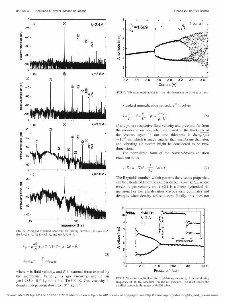
The elongations were recorded during the sweep se-quence of driving current, and output signal was captured intime domain by SR785 dynamic spectrum analyzer. Signalwas then transferred in MATLAB for further analysis, whichincludes the amplitude readings, and spectral analysis evalu-ated for increasing driving currents is shown in Fig. 5:�a� standard spectrum of nonlinear oscillator, �b� increase ofthe driving current to 2.8 A results in period doubling indi-cated by appearance of subharmonic 56 /2 Hz, with corre-sponding sequence at higher frequencies indicated by mul-tiples of 28 Hz, �c� next subharmonic at 14 Hz withcorresponding higher order harmonics is visible at I0
=3.3 A, and �d� listed subharmonic sequences share theirenergy and intensity with a virtually infinite number of sub-sequent modes.
The plot of measured vibration amplitude at fixed fre-quency as dependent on the driving current results in a bi-furcation diagram shown in Fig. 6. The first and second bi-furcations are clearly visible, which are followed, at higherdriving currents, by their further spreading in chaotic sea.
When air was pumped out from the chamber, drivingcurrent and frequency were adjusted at fixed values I0=2 Aand f =48 Hz. Air was slowly introduced thereafter in the
chamber, and chaotic state was absent at the beginning. In-troduction of air �Fig. 7� with increasing pressure left vibra-tion amplitude unaffected, in agreement with small contribu-tions of XS, RS, and viscous friction. Then, at 120 mbar, theamplitude suddenly dropped for nearly 20% and chaotic stateappeared, followed by two bifurcation pitchforks and subse-quent single pitchfork protruded up to 430 mbar. The inset ofFig. 7 shows detailed pattern between 0 and 200 mbar.
III. DISCUSSION
Dynamics of incompressible fluid is described by theNavier–Stokes equations,
FIG. 3. Air pressure dependence of real part of viscous friction.
FIG. 4. Frequency dependence of the real part of loudspeaker impedance�full line� and phase �dashed line� measured by spectrum analyzer for driv-ing currents: �a� I0=1 A, �b� I0=2 A, and �c� I0=4 A. Vertical line in �c�results from the switching of the vibration system between two degenerateamplitudes which belong to the same frequency.
043107-4 Djurek, Djurek, and Petošić Chaos 20, 043107 �2010�
Downloaded 13 Apr 2012 to 161.53.16.77. Redistribution subject to AIP license or copyright; see http://chaos.aip.org/about/rights_and_permissions
�p = �dv�dt
+ ��v� · �� · v� − · v� + F� ,
�5�
divv� = 0, v�dx� = 0,
where v is fluid velocity, and F is external force exerted bythe membrane. Value is gas viscosity, and in air=1.983�10−5 kg m−1 s−1 at T=300 K. Gas viscosity isdensity independent down to 10−3 kg m−3.
Standard normalization procedure16 involves
s� =x�
L, u� =
v�U
, p� =p − p�
� · U2 . �6�
U and p� are respective fluid velocity and pressure, far fromthe membrane surface, when compared to the thickness ofthe viscous layer. In our case thickness is �= /���10−3 m, which is much smaller than membrane diameter,and vibrating air system might be considered to be two-dimensional.
The normalized form of the Navier–Stokes equationreads out to be
u� · �u� = − �p� +1
Re· u� + F� . �7�
The Reynolds number, which governs the viscous properties,can be calculated from the expression Re= �� ·v ·L� /, wherev=�A is gas velocity and L=2A is a linear dynamical di-mension. For low gas densities viscous term dominates anddiverges when density tends to zero. Really, this does not
FIG. 5. Averaged vibration spectrum for driving currents: �a� I0=2.4 A,�b� I0=2.8 A, �c� I0=3.3 A, and �d� I0=3.6 A.
FIG. 6. Vibration amplitude�s� in 1 bar air, dependent on driving current.
FIG. 7. Vibration amplitude�s� for fixed driving current I0=2 A and drivingfrequency of 48 Hz dependent on the air pressure. The inset shows thedetailed pattern in the range of 0–200 mbar.
043107-5 Solutions of Navier–Stokes equations Chaos 20, 043107 �2010�
Downloaded 13 Apr 2012 to 161.53.16.77. Redistribution subject to AIP license or copyright; see http://chaos.aip.org/about/rights_and_permissions

happen, since velocity gradients entering in u� decreasemore strongly with decreasing density, while thickness ofviscous layer increases.
Velocity of vibrating air close to the membrane ��1 mmdistance� scales the membrane velocity, and this has beenjustified17 by the hot wire anemometry �HWA�. The spectrumof the fluctuating air derived from the velocity recorded closeto the membrane surface undergoes the chaotic vibration,and it is shown in Fig. 8�a�. It is evident a tight correspon-dence to the vibrating membrane spectrum �Fig. 8�b��. Thebasic difference between Figs. 7 and 8 is an importance ofthe viscous force. While in Fig. 7 viscous force in Navier–Stokes �NS� equation is dominant and serves as an elasticrestoring force connection to the external force �vibratingmembrane�, in Fig. 8 the first term in NS equation is domi-nant, and is indicated by the Morse wavelet convection. Airdoes not vibrate autonomously in this case, matches insteadonly the vibrating membrane surface.
Numerous attempts were being done to locate stochasticregimes of Navier–Stokes equations,18 but solutions basedupon standard numerical approximation procedures failed.The method of five mode truncation in a two-dimensionalcase, put forward by Boldrighini and Franceschini,19 startswith a harmonic expansion of the gas velocity up to fifthterm,
u�x�� = �k�0
eik�s� · �k� ·k��
�k��. �8�
Truncation revealed a set of nonlinear equations resemblingthe Lorenz equations and symmetry properties of both setsare widely quoted in textbooks.20
The third truncation mode is expressed as
�3 = − 5 · �3 − 7 · �1 · �2 + r, r = Re �k�=L
�Fk� �� . �9�
The term r is a normalized mathematical representation ofthe Reynolds number related to the real Re by summationterm given in Eq. �9�. In the subsequent work Franceschiniand Tebaldi21 evaluated the range of the normalized Rey-nolds numbers for which solutions of truncated NS equationsare stochastic in nature, and calculations give r��r�33.43,with 28.73�r��29.0. An attempt to compare these valuesto the numbers derived from the experiment involves tediousgeometrical calculations. Expression in parentheses, how-ever, might be assumed equal for both limit values of airpressure and corresponding relative values of Reynolds num-bers are to be compared in Table I.
The ratio gives Re /Re�=1.136, which is in good agree-ment with the result r /r�=1.15, reported in Ref. 20. Viscousforce at 120 mbar air, which triggers chaotic state �vibrationamplitude A=10.4 mm�, is given by XV
2 +RV2 ·�A�1 N.
This should be compared to the elastic force �27 N of thesuspended membrane evaluated at the same elongation, andthe result stresses high sensitivity of the vibration system onthe nearby gas dynamics described by Eq. �5�.
IV. CONCLUSION
It has been shown that chaotic state in the vibrating sys-tem, which consists of an anharmonic electrodynamic loud-speaker, may be triggered by air viscous force, acting onlyon the friction term in equation of motion, and this is in tightcorrespondence with observations on the anharmonic vibrat-ing systems based upon electric LRC circuits.
Loudspeaker has been operated in a closed chamber, andincrease of air pressure resulted in the chaotic state appearingat 120 mbar, while by further increase of the pressure the lastbifurcation vanishes at 430 mbar. The ratio of correspondingReynolds numbers is in agreement with those reported byFranceschini and Tebaldi, and calculated from the equations,indicating the five mode truncated nonlinear Navier–Stokesequations describing a two-dimensional incompressible fluid.
FIG. 8. Spectral analysis of a chaotic state: �a� the fluctuating air velocityrecorded by the hot wire anemometric �HWA� probe, �b� the amplitude ofthe vibrating membrane.
TABLE I. Introductory parameters for evaluation of limiting Reynolds num-bers.
Re�=476 Re=538
A �mm� 10.4 5.85� �kg m−3� 0.145 0.518v �m s−1� 3.13 1.76L �mm� 20.8 11.7 �kg m−1 s−1� 1.983�10−5 1.983�10−5
043107-6 Djurek, Djurek, and Petošić Chaos 20, 043107 �2010�
Downloaded 13 Apr 2012 to 161.53.16.77. Redistribution subject to AIP license or copyright; see http://chaos.aip.org/about/rights_and_permissions

ACKNOWLEDGMENTS
This paper is dedicated to Professor Boran Leontić onthe occasion of his 80th birthday.
1E. Ott, Chaos in Dynamical Systems, 2nd ed. �Cambridge UniversityPress, Cambridge, England, 2002�.
2H. G. Schuster and W. Just, Deterministic Chaos �Wiley-VCH VerlagGmbH & Co. KGaA, Weinheim, 2005�.
3P. S. Linsay, Phys. Rev. Lett. 47, 1349 �1981�.4R. W. Rollins and E. R. Hunt, Phys. Rev. Lett. 49, 1295 �1982�.5J. Testa, J. Pérez, and C. Jeffries, Phys. Rev. Lett. 48, 714 �1982�.6P. M. Morse and K. U. Ingard, Theoretical Acoustics �Princeton UniversityPress, Princeton, NJ, 1986�, p. 847.
7P. M. Morse, Vibration and Sound, 2nd ed. �McGraw-Hill, New York,1948�, p. 326.
8H. Schurer, Thesis, University of Twente Enschede, 1997.9R. M. Aarts and A. J. E. M. Janssen, J. Acoust. Soc. Am. 113, 2635�2003�.
10L. D. Landau and E. M. Lifshitz, Mechanics, Course of Theoretical
Physics, 3rd ed. Vol. 1 �Elsevier, Butterworth-Heinemann, Oxford, 1976�,pp. 84–93.
11I. Djurek, D. Djurek, and A. Petošić, Acta. Acust. Acust. 94, 629 �2008�.12J. D. Reiss, I. Djurek, A. Petošić, and D. Djurek, J. Acoust. Soc. Am. 124,
2031 �2008�.13D. Djurek, I. Djurek, and A. Petošić, Proceedings of 122nd AES Conven-
tion, Vienna, Austria, 2007 �Convention paper 7077�.14I. Djurek, D. Djurek, and A. Petošić, Proceedings of 122nd AES Conven-
tion, Vienna, 2007 �Convention paper 7075�.15K. Bennewitz and H. Rötger, Phys. Z. 37, 578 �1936�.16P. K. Kundu and I. M. Cohen, Fluid Mechanics, 3rd ed. �Elsevier Aca-
demic, San Diego, CA, 2004�, p. 301.17I. Djurek, A. Petošić, and D. Djurek, Proceedings of 123rd AES Conven-
tion, New York, 2007 �Convention paper 7256�.18R. Temam, Navier-Stokes Equations, Theory and Numerical Analysis
�American Mathematical Society, Providence, 2000�.19C. Boldrighini and V. Franceschini, Commun. Math. Phys. 64, 159
�1979�.20R. Gilmore and Ch. Letellier, The Symmetry of Chaos �Oxford University
Press, Oxford, 2007�, p. 7.21V. Franceschini and C. Tebaldi, J. Stat. Phys. 21, 707 �1979�.
043107-7 Solutions of Navier–Stokes equations Chaos 20, 043107 �2010�
Downloaded 13 Apr 2012 to 161.53.16.77. Redistribution subject to AIP license or copyright; see http://chaos.aip.org/about/rights_and_permissions