Stochastic finite element based nonlinear dynamic instability ...
32
Advances in Aircraft and Spacecraft Science, Vol. 3, No. 4 (2016) 471-502 DOI: http://dx.doi.org/10.12989/aas.2016.3.4.471 471 Copyright © 2016 Techno-Press, Ltd. http://www.techno-press.org/?journal=aas&subpage=7 ISSN: 2287-528X (Print), 2287-5271 (Online) Stochastic dynamic instability response of piezoelectric functionally graded beams supported by elastic foundation Niranjan L. Shegokar a and Achchhe Lal Department of Mechanical Engineering, S.V.N.I.T. Surat-395007, India (Received November 5, 2015, Revised April 19, 2016, Accepted June 19, 2016) Abstract. This paper presents the dynamic instability analysis of un-damped elastically supported piezoelectric functionally graded (FG) beams subjected to in-plane static and dynamic periodic thermo- mechanical loadings with uncertain system properties. The elastic foundation model is assumed as one parameter Pasternak foundation with Winkler cubic nonlinearity. The piezoelectric FG beam is subjected to non-uniform temperature distribution with temperature dependent material properties. The Young's modulus and Poison's ratio of ceramic, metal and piezoelectric, density of respective ceramic and metal, volume fraction exponent and foundation parameters are taken as uncertain system properties. The basic nonlinear formulation of the beam is based on higher order shear deformation theory (HSDT) with von-Karman strain kinematics. The governing deterministic static and dynamic random instability equation and regions is solved by Bolotin's approach with Newmark's time integration method combined with first order perturbation technique (FOPT). Typical numerical results in terms of the mean and standard deviation of dynamic instability analysis are presented to examine the effect of slenderness ratios, volume fraction exponents, foundation parameters, amplitude ratios, temperature increments and position of piezoelectric layers by changing the random system properties. The correctness of the present stochastic model is examined by comparing the results with direct Monte Caro simulation (MCS). Keywords: dynamic instability; functionally graded beams; Bolotin’s approach; standard deviation; first order perturbation method; random system properties; elastic foundation; Monte Carlo simulation 1. Introduction FG Materials are the advanced inhomogeneous composite materials, composed of two or more constitutes phases of metal and ceramic spatially varied in controlled directions by the variation of the volume fraction exponent of constituent materials. The metal constituent portion provides the mechanical strength, and toughness while, ceramics constituent provides high temperature withstanding ability and corrosion resistance. The appropriate mixing of metal and ceramic constituents open new possibilities for researchers to examine the performance and stabilities of thermal barrier of turbine blades, heat exchanger tubes, thermoelectric generators, furnace linings, cutting tools, metal ceramic joints etc. A variety of light-weight heavy load bearing structural components such as aircraft wings, Corresponding author, Assistant Professor, E-mail: [email protected], [email protected] a Ph.D. Student, E-mail: [email protected]
-
Upload
khangminh22 -
Category
Documents
-
view
1 -
download
0
Transcript of Stochastic finite element based nonlinear dynamic instability ...

Advances in Aircraft and Spacecraft Science, Vol. 3, No. 4 (2016) 471-502
DOI: http://dx.doi.org/10.12989/aas.2016.3.4.471 471
Copyright © 2016 Techno-Press, Ltd. http://www.techno-press.org/?journal=aas&subpage=7 ISSN: 2287-528X (Print), 2287-5271 (Online)
Stochastic dynamic instability response of piezoelectric functionally graded beams supported by elastic foundation
Niranjan L. Shegokara and Achchhe Lal
Department of Mechanical Engineering, S.V.N.I.T. Surat-395007, India
(Received November 5, 2015, Revised April 19, 2016, Accepted June 19, 2016)
Abstract. This paper presents the dynamic instability analysis of un-damped elastically supported piezoelectric functionally graded (FG) beams subjected to in-plane static and dynamic periodic thermo-mechanical loadings with uncertain system properties. The elastic foundation model is assumed as one parameter Pasternak foundation with Winkler cubic nonlinearity. The piezoelectric FG beam is subjected to non-uniform temperature distribution with temperature dependent material properties. The Young's modulus and Poison's ratio of ceramic, metal and piezoelectric, density of respective ceramic and metal, volume fraction exponent and foundation parameters are taken as uncertain system properties. The basic nonlinear formulation of the beam is based on higher order shear deformation theory (HSDT) with von-Karman strain kinematics. The governing deterministic static and dynamic random instability equation and regions is solved by Bolotin's approach with Newmark's time integration method combined with first order perturbation technique (FOPT). Typical numerical results in terms of the mean and standard deviation of dynamic instability analysis are presented to examine the effect of slenderness ratios, volume fraction exponents, foundation parameters, amplitude ratios, temperature increments and position of piezoelectric layers by changing the random system properties. The correctness of the present stochastic model is examined by comparing the results with direct Monte Caro simulation (MCS).
Keywords: dynamic instability; functionally graded beams; Bolotin’s approach; standard deviation; first
order perturbation method; random system properties; elastic foundation; Monte Carlo simulation
1. Introduction
FG Materials are the advanced inhomogeneous composite materials, composed of two or more
constitutes phases of metal and ceramic spatially varied in controlled directions by the variation of
the volume fraction exponent of constituent materials. The metal constituent portion provides the
mechanical strength, and toughness while, ceramics constituent provides high temperature
withstanding ability and corrosion resistance. The appropriate mixing of metal and ceramic
constituents open new possibilities for researchers to examine the performance and stabilities of
thermal barrier of turbine blades, heat exchanger tubes, thermoelectric generators, furnace linings,
cutting tools, metal ceramic joints etc.
A variety of light-weight heavy load bearing structural components such as aircraft wings,
Corresponding author, Assistant Professor, E-mail: [email protected], [email protected] aPh.D. Student, E-mail: [email protected]
Niranjan L. Shegokar and Achchhe Lal
helicopter rotors, turbine blades, spacecraft antennae, flexible satellites, robot arms, and long-span
bridges can be modeled as FGM beam members. These structural components are sometimes may
be subjected to different periodic in-plane and/or out-of-plane loadings and become dynamically
unstable and produce parametric resonance conditions. For optimum high performance and safe
design of such components, there is need of proper understanding of their instability behaviors and
regions in stochastuic sense.
For health monitoring purpose, attachment of surface bonded piezoelectric layers at the top and
bottom of FG structures are needed, to make the structures, smart by self monitoring and self
controlling performance capabilities under the action of external stimuli. Hence, effect of
piezoelectric layers on the structural performance are extremely needed.
The FG beams supported by elastic foundations have been passed some important messages to
the engineering community for stability and flexibility purposes. Such structures are being used as
shocks observers and may be modeled as aflexible beam in ships and bridges, automobiles,
spacecraft arms, footings, foundation of spillway dams, deep wells and civil buildings in cold
regions. From practical point of views, Pasternak elastic foundation with Winkler cubic
nonlinearity is proved as a more appropriate model for design prospective due to controlling of
displacements along both of the longitudinal and transverse directions.
The volume fraction exponents, material properties of FG structures and surface bonded
piezoelectric layers, density of constituent materials, and foundation parameters can be modeled as
statistical random system variables. It is because of complete control of these random system
variables at each design level is very difficult and challenging. The presence of these random
system properties, may have significantly affected the structural performance particularly,
dynamic instability. Hence, the effect of dispersion of these random system properties from their
mean values in terms of standard deviation (SD) using stochastic approaches is needed for safe and
reliable design.
Comprehensive study of deterministic dynamic stability problems for elastic structures of
different shapes of beams, plates and shells is reported by many researchers. Notably among them
are Abbas and Thomas (1978), Ahuja and Duffield (1975), Bolotin (1964), Evan-Iwanowski
(1965), Bert and Birman (1987), Chen and Yang (1990), Ganpati et al. (1994), Ganpati et al.
(1999), Datta et al. (1982), Patel et al. (2006), Wang and Dawe (2002), Moorthy et al. (1990),
Srinivasan and Chellapandi (1986), Chattopadhyay and Radu (2000), Baldinger et al. (2000), Hu
and Tzeng (2000), Singha et al. (2001), Young and Chen (1994), Liao and Cheng (1994), Sahu
and Datta (2007), Wu et al. (2007), Yang et al. (2004), Pradyumna and Bandyopadhya (2010), Ng
et al. (2001), Zhu et al. (2005), Darabi et al. (2007), Ke and Wang (2011), Mohantya and Dash
(2011), Fu et al. (2012).
The fieldsrelated to stochastic analyses for the dynamic stability analysis of FG structures are
very limited.Few efforts have been made in the past by the researchers, to quantify the different
level of random system properties and their effects of structural performance using various
probabilistic approaches.
In this direction, there are different probabilistic approaches are used for quantifying the several
aspects of uncertainties at different variability levels in the materials, geometrical and/or external
excitations as random processes (Kleiber and Hien 1992, Nigam and Narayana 1994, Iwankiewicz
and Nielsen 1999, Nayfeh 1993, Namachchivaya et al. 2003). Shinozuka and Astill (1972)
evaluated the expected mean value and variance of the vibration and buckling eigenvalues of a
beam-column with random geometric and material properties using computerized Monte Carlo
simulation and investigated the accuracy of perturbation method. Vanmarcke and Grigoriu (1983)
472

Stochastic dynamic instability response of piezoelectric functionally graded beams...
evaluated the second order statistics of deflection response of beam with random material
properties through correlation method using direct MCS. Chang and Chang (1994) investigated the
statistical dynamic responses of a non-uniform beam by using the stochastic finite element method
in conjunction with perturbation technique and MCS with random change in Young’s modulus of
elasticity. Liu et al. (1986) presented the direct Monte Carlo simulation, stochastic finite element
method and Hermite-Gauss quadrature probabilistic approaches to evaluate the statistics of
dynamic response of truss and beam problem. Dey (1979) presented the applications of the
stochastic finite element method, to analyze the response of multi-degree linear elastic structures
subjected to stationary random stochastic loadings using matrix inversion and normal mode
method. Ibrahim (1987) presented a review paper pertaining to structural dynamics with parameter
uncertainties for two bar truss problems and highlighted the importance of perturbation,
variational, asymptotic, and integral equation methods. Kareem and Sun (1990) investigated the
influence of various level of damping uncertainties in the system dynamic response using second
order perturbation technique (SOPT). Kapania and Perk (1996) evaluated the second-order
sensitivity of the transient response and sensitivity with respect to various system parameters to
single- and two-degree-of-freedom structural linear and nonlinear dynamic systems using central
difference numerical approach. Zhao and Chen (1998) developed the new dynamic stochastic
finite element method (FEM) by assuming uncertain dynamic shape function matrix based on
dynamic constraint mode to study the dynamic response of spatial frame structures. Giuseppe
(2011) presented a fully constraint theoretical framework of finite element (FE) based analysis
with precise, intervalued and fuzzy probabilistic methods of linear mechanical systems. Rollot and
Elishakoff (2003) used the conventional FEM combined with perturbation techniques in stochastic
sense for getting astructural bending response of the beam with stochastic stiffness subjected to
either deterministic or random loading. Ren et al. (1997) proposed a new version of FEM in
conjunction with perturbation technique and MCS for mean and covariance function of
displacements for bending beam using newly established variational approach. Stefanou et al.
(2009) provided a state-of-art reviewed the applications and developments of stochastic finite
element methods (SFEM) from past, recent and future aspects of the engineering applications.
Yang et al. (2005) studied the thermo-mechanically induced bending responses of functionally
graded plate with random system properties using Reddy’s higher order shear deformation theory
(HSDT) combined with FOPT. Raj et al. (1998) obtained the static response of graphite epoxy
composite laminates with random material properties using HSDT combined with MCS. Onkar
and Yadav (2005) evaluated the transverse central deflection response of laminated composite
plate with random material properties and random external loading using Kirchoff-Love plate
theory with von-Karman nonlinearity through FOPT. Lal et al. (2012a, 2012b, 2013) evaluated the
second order statistics of initial and post buckling analysis of laminated composite and
functionally graded plates subjected to thermo-mechanical loadings. They used HSDT based C0
nonlinear FEM combined with direct iterative based stochastic finite element methods using
FOPT. Jagtap et al. (2011, 2013) evaluated the second order statistics of bending analysis of FGM
plate using HSDT combined with direct iterative based nonlinear FEM in conjunction with FOPT.
Shegokar and Lal (2013a, 2013b, 2014) evaluated the second order statistics of thermo-electro-
mechanically induced bending, buckling and vibration response of theFGM beam with random
system properties using HSDT combined with nonlinear FEM combined with FOPT and MCS. Lal
et al. (2015) evaluated the finite element based thermo-mechanically induced post buckling
response of elastically supported laminated composite plate with random system properties using
HSDT with von-Karman nonlinear strain kinematics combined with second order perturbation
473

Niranjan L. Shegokar and Achchhe Lal
method (SOPT).
To the best of this author’s knowledge, based on the HSDT, a stochastic thermo-mechanically
induced nonlinear dynamic stability analysis of elastically supported FGM beams containing
piezoelectric layers is not yet widely available in the literature. An intuitive prediction about
instability behaviors and regions in terms of mean and SD of FGM beams subjected to in-plane
non-conservative forces by accounting the random system properties at various variability levels
are examined. In this study, a stochastic finite element formulation based on FOPT through HSDT
with von-Karman nonlinearity is developed. In order to evaluate the dynamic instability regions,
the Mathieu-Hill types equation using Bolotin’s method is presented. The effect of slenderness
ratios, volume fraction exponents, foundation parameters, amplitude ratios, temperature
increments and position of piezoelectric layers by changing the uncorrelated random system
properties on the mean and SD of dynamic instability analysis and regions of un-damped
elastically supported FGM beam with surface bonded piezoelectric layers are examined.
2. Formulations
2.1 Geometric configurations and FGM properties
Let us consider a FGM rectangular beam with surface bonded piezoelectric layers supported by
a Pasternak elastic foundation with Winkler cubic nonlinearity. The respective length and
thickness of FGM beam are represented by L and h with the coordinate system (x, z) as shown in
Fig. 1. At the top and bottom of the FGM beam, surface bonded piezoelectric layers of equal
thickness (hp) are attached. The total thickness of FGM beam with piezoelectric layers is
represented by H. It is assumed that a perfect bonding are existed among the FGM beam, surface
bonded piezoelectric layers and supporting elastic foundations.
The foundation reaction per unit area (p) exerted by supporting Pasternak elastic foundation
with Winkler cubic nonlinearity can be represented as (Shegokar and Lal 2013a, 2013b)
3 2 2
1 3 2p K w K w K w x (1)
Fig. 1 Geometry of a piezoelectric FGM beam supported by elastic foundation
FGM
Piezo PZT-5
z (w) L
h
hp b
x (u) H
Linear layer
Nonlinear layer
Shearing layer
Nx(t)
(u)
474

Stochastic dynamic instability response of piezoelectric functionally graded beams...
where w, K1, K3 and K2 and are the transverse displacement of piezoelectric FGM beam, Winkler
(spring) linear, nonlinear and Pasternak (shear) foundations, respectively.
It is assumed that FGM beam is composed from mixing of ceramic and metal constituents and
the material compositions are varied continuously in the thickness direction, such a way that the
top surface i.e., z=h/2 of the beam is ceramic rich, whereas the bottom surface i.e., z=-h/2 is metal
rich.
The effective material properties P, can be expressed as
1
n
k k
k
P P V
with1
1n
k
k
V
(2)
where Pk and Vk are the material properties and volume fraction of the constituent material k, that
satisfying the volume fraction of all constituent materials.
For temperature dependent material properties, The effective material properties (P) can be
written as
2 3
0 1 1 2 31P P P T PT PT PT (3)
where Pi (i = -1, 0, 1, 2, 3) are the coefficients of temperature T(K) and defined in Table 1.
For a FGM beam, the volume fraction of constituent material (k) in the thickness direction (z)
can be written as
n
k
z 1V z
h 2
(4)
where n is the volume fraction exponent and varies 0 n through the beam thickness. (3)
The material properties of a FGM beam vary through thickness direction according to a power
law distribution which is expressed as (Fu et al. 2012)
( ) ( - )c m k mP z P P V z P (5)
where Pm and Pc represent the properties of metal and ceramic constituents, respectively.
2.2 Displacement field model The modified displacement field components based on Co continuity derived from Reddy’s
HSDT with seven degrees of freedom along coordinate directions can be written as (Shegokar and
Lal (2013a, 2013b, 2014), Heyliger and Reddy (1988)
3
0 x x2
4u( x,z ) u ( x ) z z ( w x )
3h and
0w( x,z ) w ( x ) (6)
where u and w are the displacements along x and z directions, respectively. The parameters u0, w0
are the displacements of mid-plane, respectively. The symbols ψx and θx are rotation and slope
along x-direction, respectively.
The displacement vector consisting of four degree of freedoms (DOFs) can be written as
x xq u w
(7)
475

Niranjan L. Shegokar and Achchhe Lal
2.3 Stress- Strain relationship
The nonlinear thermo-piezoelectric material constitutive relationship between stress and strain
for plane stress case, assuming large deformation theory with von-Karman nonlinearity can be
written as
zQ e E (8)
where [Q], {ε}, [e] and {Ez} are the stiffness coefficient matrix, the stain vector, piezoelectric
constant matrix and electric field vector for the one dimensional FGM beam, respectively and
defined as
11 11
55 55
0 0, , ,
0 0
p
l nl t z
Q eQ E e E
Q e x
(9)
here
11 552
;2 11
E z E zQ Q G z
(9a)
The linear stain vector {εl} using HSDT can be written as
l lT (9b)
where [T] is the unit step vector with function of z and defined in Appendix A-1 and l is the
reference plane linear strain tensor written as
0 0 2 0 2
1 1 1 5 5l k k k (9c)
From Eq. (7), Eq. (9c) can be written as
l L q (9d)
where [L] is the differential operator defined in Appendix A-1.
The nonlinear strain vector {εnl} by assuming von-Karman strain kinematics is written as
1
2nl nl nlA
(10)
01
20 0
nl
w
A x
0
nl
w
x
(11)
The thermal strain vector {εT} and can be written as
0T x T (12)
where αx and ΔT are the thermal expansion coefficient along x direction and nonuniform
temperature change, respectively.
The non-uniform change in temperature (ΔT) along the thickness direction can be written as
Kiani and Eslami (2010)
476

Stochastic dynamic instability response of piezoelectric functionally graded beams...
0T T z T (13)
where, T0 is the reference temperature, i.e., room temperature and assumed to be 27°C.
The parameter T(z) is the steady state nonuniform temperature distribution and can be written
as Shegokar and Lal (2013a)
'
2 2
2 2
2 2
p p
f
p p p
T z h z h h
T z T z h z h
T z h h z h h
(14)
where Tp, T′p and Tf (z) are the temperature of the lower piezoelectric layer, upper piezoelectric
layer and FGM layer,respectively.
The piezoelectric strain field vector Ez can be expressed as
(0)
zE T E (15)
where Tϕ and E0
is the electric field potential operator and electric field vector respectively and
defined as
21 0 0
0 0 0 1
z zT
z
0
10
2
0 0
{E } 0 0
0 0
x
x
x
(15a)
From Eq. (8), The parameters e11 and e13 are defined as Shegokar and Lal (2013b)
11 11 11pe d Q and 15 15 55 pe d Q (16)
where d11 and d15 are the dielectric constants. The parameters Q11p and Q55p are defined as
11 21
p
p
p
EQ
and
55
2 1
p
p
p
EQ
(16a)
From Eq. (8), the electric field vector Ez can be written as
p
zEx
(16b)
where p is the electric field potential and can expressing as
p zN
(16c)
here, N and z
are the shape function matrix and electric potential DOFs vector and can be
expressed as
T
z L U
(16d)
The parameters L and U are electric potentials corresponding to lower and upper piezoelectric
477

Niranjan L. Shegokar and Achchhe Lal
layers, respectively.
2.4 Governing equation The equation of motion can be derived using Hamilton’s principle and expressed as
2
1
0 t
tT U W dt (17)
where T, U and W are the kinetic energy, the strain energy and the work done by the con
conservative buckling load of FGM beam with surface bonded piezoelectric layers supported by
elastic foundation, respectively.
2.5 strain energy of the piezoelectric FGMs beam
The elastic strain energy of the piezoelectric FGM beam is written as Lal et al. (2015)
1 1
U=2 2
T T
z p
A A
dA E D dA , (18)
where {Dp} is the electric field displacement vector and can be written as
T
p zD e E (19)
here [k] is the dielectric displacement coefficient matrix and defined as
11
33
0
0
(19a)
Substituting Eq. (8), Eq. (19) in Eq. (17), once as obtains
1
2
T T T
z z z
A
U Q eE E e E dA
(20)
Substituting Eqs. (9b), (9d) and Eq. (11) in Eq. (18), the linear potential energy (Ul) of the
piezoelectric FGMs beam can be further written as
1 1 2
1
2
T T T T T T T T T T T
l p p p p t
A
U q L DLq q L D L L D Lq L D L q L F dA
(21)
Where D, D1 and D2, are the elastic stiffness matrix of FGM and piezoelectric material,
respectively, and defined in Appendix A-2 (a)-(c) substituting Eq. (9d) and Eq. (10c) in Eq. (17),
the nonlinear potential energy (Unl) of piezoelectric beam can be further written as
3 4 5 6 7
1
2
T T T T T T T T T T
NL nl nl nl nl nl nl nl nl nl nl nl nl
A
U q L D A A D qL A D A A D L L D A dA
(22)
where D3, D4, D5, D6 and D7 are the elastic stiffness matrix of FGM and piezoelectric material,
respectively and defined in Appendix A-3.
2.6 Strain energy due to elastic foundation
478

Stochastic dynamic instability response of piezoelectric functionally graded beams...
Using Eq. (1), the strain energy (Uf) due to elastic foundation assuming Pasternak elastic
foundation with Winklar cubic nonlinearity can be written as (Shegokar and Lal 2013a, 2013b)
2
2 4
1 2 3
21 3
2 3
1
2
0 01 1
02 2 0
fA
T T
A A
wU K w K K w dA
x
w w w wK K w
dA dAw w w wK K
x x x x
(23)
Eq. (23) can be rewritten as
1 1 1 1
2 2 2 2
T T
f f fl f f fnl fA A
U D dA D dA
(23a)
where f fL w with
0 1 0 0
0 0 0fL
x
1
2
0
0fl
KD
K
2
3 0
0 0fnl
K wD
2.7 Work done due to external in-plane mechanical loading
The potential due to external work done by the action of thermo-mechanical in-plane loading is
written as
2
1
2
x
A
wW V N dA
x (24)
where, Nx is the in-plane thermo-mechanicalloading known as axial compressive force and
expressed in the following form
0 0 T
xN N N with
/ 2
3
0 11
/ 2
(1, , )( )
h
T
x
h
N z z Q Tdz (25)
where Nx and Nt are the in-plane mechanical and thermal loads, respectively.
2.8 Kinetic energy of the FGM beam The kinetic energy (T) of the vibrating FGM beam can be expressed as
v
T dvuuT }ˆ{ }ˆ{2
1 (26)
whereρ and are the density and velocity vector of the FGM beam, respectively.
2 22 2
0 2 0 2
1 1
2 2
l h l h T
h hT z u w dzdx z N N dzdx (26a)
u
479

Niranjan L. Shegokar and Achchhe Lal
3. Finite element formulation
The governing equation of the piezoelectric FGMs beam supported by elastic foundation, is
derived using Hamilton principle given in Eq. (17). The FE analysis is performed usinga 1-D
Hermitian beam element with 4 DOFs per node.
Displacement vector {q} in Eq. (7) and Eq. (15d) can be written in terms of shape functions as
1 1
NN NN
i i i i
i i
q N q N
(27)
where i represent node number and Ni is shape function at ith node.
For an element, the displacement field vector, and the electric potential vector can be written as
( )( ) ( )ee e
iq N q and ( )( )( )
eee
N q (27a)
Substituting Eq. (28) in Eq. (21), and summed over all elements using finite element model Eq.
(27), Eq. (21) linear strain energy of the piezoelectric FGMs beam can be rewritten as
( ) ( ) ( ) ( ) ( ) ( ) ( ) ( ) ( ) ( ) ( ) ( ) ( )
1
1 1 2
NE
e e T e e e T e e e T e T e e T e e
l
i
U q K q q K q q K q q K q (28)
where
( )
( ) ( ) ( )1,
2
e
e e T e
A
K B DB dA( )
( ) ( ) ( )
1
11 ,
2
e
e e T e
A
K B D B dA and( )
( ) ( ) ( )
2
12 ,
2
e
e e T e
A
K B D B dA (29)
Here K(e), KI(e) and K2(e) are the element bending stiffness matrix, coupling matrix and dielectric
matrix, respectively. The strain displacement matrix [B] for plate and piezoelectric [Bg] can be
written as
( ) ( )
,e e
iB L N and ( ) ( )
.
e eB L N (30)
with
( )
1 2 3 e
NNB B B B B and [Bi] = [L]Ni. with i=1, 2, 3,……NN (30a)
the parameters L and Ni (i=1,...,6) are defined in Shegokar and Lal (2013a)
Similarly, using Eq. (28) in Eq. (22), and summed over all elements using finite element model
Eq. (27), the nonlinear strain energy of thepiezoelectric FGMs beam can be rewritten as
( ) ( ) ( ) ( ) ( ) ( ) ( ) ( ) ( ) ( ) ( ) ( ) ( ) ( ) ( )
1 2 3 4 5
1
{ } { } { } { } } { } { } { }NE
e e T e e e T e e e T e e e T e e e T e e
nl
i
U q k q q k q q k q q k q q k q
(31)
where the element bending stiffness matrix are
( ) ( ) ( ) ( ) ( ) ( )
1 3 2 4
1 1{ }{ } { } { }
2 2e e
e e T e e e e T e T
A A
k B D A G dxdy k G A D dxdy
( ) ( ) ( ) ( )
3 5
1{ } { }
2 e
e e T e T e e
A
k G A D G dxdy
(31a)
480

Stochastic dynamic instability response of piezoelectric functionally graded beams...
and the coupling matrix are
( ) ( ) ( ) ( ) ( ) ( )
4 6 5 7
1 1{ } { } { }
2 2e e
e e T e T e e T e e
A A
k G A D dxdy k B D G dxdy
(31b)
Similarly, strain energy due to foundation after summing over all the elements using Eq. (27),
Eq. (23) can be rewritten as
1 1
T TNE NEe e e e e e e
f fl fnl
i i
U q K q q K q
(32)
where
( )
( ) ( )1,
2
e
e e T e
fl f fl f
A
K B D B dA and
( )
( ) ( )1
2
e
e e T e
fnl f fnl f
A
K B D B dA are the linear and nonlinear
foundation stiffness matrix and [Bf] is the strain displacement matrix due to foundation and
defined as
( ) ( )
e e
f f iB L N (33)
Using afinite element model as Eq. (27), potential of work done due to thermo-mechanical
loading as given Eq. (24) can also be written as
1
TNE
e e e e
x g
i
W q N K q (34)
Where Nx, [Kg](e) is the defined as a thermal buckling load and elemental geometric stiffness
matrix, respectively.The value of [Kg] is defined in
( )
( ) ( )1
2
e
e e T e
g g o g
A
K B N B dA
Using finite element analysis Eq. (27), after summing over all the elements, the kinetic energy
of FGMs beam as given in Eq. (26a) can be written as (Shegokar and Lal 2013).
. .
1
e T eNEe
e
T q M q dA
(35)
where, [M] is the global consistent mass matrix.
Adopting numerical integration, the element bending stiffness matrix consist of linear and
nonlinear, coupling matrix, dielectric stiffness matrix, foundation stiffness matrix, geometric
stiffness matrix and mass matrix can be obtained by transforming expression in (x) coordinate
system to natural coordinate system (ξ) using Gauss quadrature method.
Substituting Eq. (28), Eq. (31), Eq. (32), Eq. (34) and Eq. (35) in Eq. (17), once obtains as (Lal
et al. 2015)
1
1 2
00 0
00 0 0 0
flg
tTfnl
K K KM q K q q qF
K K K
(36)
The Eq. (36) can be rewritten as
x g tM q K N K q F (37)
481

Niranjan L. Shegokar and Achchhe Lal
where 1
_ _
T
q f fnl q phi phi q phiK K K K K K K with ( ) ( ) ( )
1 2
1
( )NE
e e e
q
e
K K K K
( ) ( )
_ 4
1
( 1 )NE
e e
q phi
e
K K K
; ( )
1
2NE
e
phi
e
K K
; ( )
1
NEe
t t
e
F F
;
1
NEe
fl fl
e
K K
;
1
NEe
fnl fnl
e
K K
;
1
NEe
e
M m
The parameters qK ,
_q phiK , 1
TK , phiK , Ft, Kfl, Kfnl and M are the global elastic stiffness
matrix, coupling matrix between elastic mechanical and electrical effect, dielectric stiffness
matrix, force vector and linear and nonlinear foundation stiffness matrix and mass matrix,
respectively.
4. Instability analysis
The stability analysis of piezoelectric FG beam is performed by expressing the uniform
pulsating axial compressive force Nx, in terms of a static and dynamic components, both are them
written in terms of the critical buckling load, Ncr, and expressed as (Datta and Chakraborti 1982,
Pryadumna and Bandyopadhyay 2010)
cos cos x s t cr crN N N t N N t (38)
where Ns and Nt are the static and dynamic portion of the in-plane load, respectively.The
parameters α, β and Ω are the static load factor, dynamic load factors and frequency of excitation,
respectively.
Substituting Eq. (38), in Eq. (37), the governing equation of beam in the form of instability
equation can be further written as
[ ]{ } cos { } 0 cr g cr gM q K N K N K t q
(39)
Eq. (39) is known as Mathieu-hill equation, describes the nonlinear instability behavior of the
piezoelectric FGM beam of second order partial differential equation with periodic coefficients.
The boundaries between stable and unstable regions are formed by periodic solution of period T
and 2T, where T=2Π/ω. The boundaries of stable and unstable regions within period 2T are of
great practical importance and the solutions are performed in the form of trigonometric series as
1,3,5
{t} sin sin2 2
k k
k
k t k tq a b
(40)
Substituting, Eq. (40) into Eq. (39) and considering only the first term of the series for the
instability regions and then equating the coefficients of sin(ωt/2)cos(ωt/2), Eq. (39) reduced to the
form as
22
[ ] { } 02 4
cr gK N K M q
(41)
Eq. (41) represents an eigenvalue problem forthe known value of α, β and Ncr. The two
conditions under the plus and minus signs corresponded to two boundaries (left and right) of the
482

Stochastic dynamic instability response of piezoelectric functionally graded beams...
instability regions are represented by β. The eigenvalues (Ω/ω), give the boundary frequencies
(known as disturbing frequency or resonance frequency) of the instability regions for the given
values of α and β. The problem is now reduced to that of finding the critical excitation frequency
from the above equation. For a given value of α, the variation of the eigenvalue (Ω/ω) with respect
to β can be found using standard eigenvalue algorithms. In Eq. (41), the value of Ncr is evaluated
by assuming the static buckling critical load. The plot of such variations in the β- (Ω/ω) plane
shows the instability regions of the FGM beam subjected to the periodic axial load.
In the indirect approach, for the evaluation of transverse dynamic central deflection response
internal in-plane force vector atthe equilibrium condition for the given time t+Δt are needed. The
in-plane internal force using Newton's second law of motion can be written as (Ganpathi et al.
1994, 1999)
[ ]{ } ( ) 0
t t
t tM q N q q
(42)
where { }t tq and
t tq
are the vectors of the nodal accelerations and displacement at time t+Δt,
respectively.Substituting [ ]{ } t tM q from Eq. (42) in Eq. (39), once obtains as
( ) coscr g t tt tN q q K N t K q
(43)
The, internal in-plane force vector ( )
t tN q q from Eq. (43) can be further written as
( ) ( ) ( )T tt t tN q q N q q K q q
(44)
where, ( ) tN q q is the internal in-plane force at time t and
t t tq q q
. The
parameter ( )TK q is the tangent stiffness matrix and defined as
( ) cos
T cr g t ttK q K N t K q (45)
Substituting Eq. (45) into Eq. (42), one obtains the governing equation at t+Δt as
[ ]{ } ( ) ( )t t T t tM q K q q N q q
(46)
Eq. (46) is the nonlinear forced vibration equation and for thesolution of this equation, the
direct iterative procedure combined withthe Newton-Raphson method with required convergence
less than 1% tolerance is used.
For solution of Eq. (46) nonlinear Equilibrium is achieved for each time step through a
modified Newton Raphson iteration scheme until the required convergence criteria is satisfied
within the specific tolerance limit of less than 1%.
At time t+Δt, Eq. (46) can be further written as
*[ ]{ }t t t tK q F
(47)
where [K*] and {F}t are the effective stiffness matrix and effective force vector, respectively
defined as
2
1[ ] K ( )TK M q
t
(48)
483

Niranjan L. Shegokar and Achchhe Lal
2 2
1 1 1 2
2t t t tF M q q q
t t
(49)
here { }t tq and { }t tq
are the velocity and acceleration vectors at time t+Δt, respectively and are
written as
{ } { } 1 { } { }t t t t t tq q t q q
(50)
2
2
1 1{ } { } { } { } { }
2t t t t t t tq q q t q t q
t
(51)
The parameters β and γ are constants whose values depend on the finite difference used in the
calculations. Here, the constant-average acceleration method is used which is implicit and
unconditionally stable. Although the velocity vector is not required in standard dynamic Eq. (49),
however, it is presented here because it will be needed subsequently. For this method the value of
β and γ are taken as 1/4 and 1/2, respectively.
Eq. (51) is the dynamic stability deflection problem which is random in nature, being
dependent on the system properties. Therefore, the eigenvalue and eigenvectors also become
random. In deterministic environment, the solution of Eq. (51) is evaluated using standard time
integration solution procedure such as central deflection, Wilson’s, Newmark etc. However, in
random environment, it is not possible to obtain the solution using the above mentioned numerical
methods.
For this purpose, the direct iterative method is first time successfully combined with mean
cantered FOPT i.e., direct iterative based stochastic finite element method (DISFEM), developed
by authors for dynamic instability analysis to obtain the second order statistic (mean and SD) of
nonlinear dynamic transverse central deflection.
5. Solution approach
The nonlinear random forced vibration problem as given in Eq. (52) is solved by employing a
direct iterative method in conjunction with the mean centered perturbation perturbation technique
assuming that the random changes in transverse displacement during iterations and time does not
affect the nonlinear stiffness matrix as the procedure given by Shegokar and Lal (2012), Jagtap et
al. (2011). The systematic solution procedure for stochastic dynamic stability analysis using direct
iterative based stochastic finite element method (DISFEM) is shown in Fig. 2.
5.1 Perturbation method In the given Eq. (39), the operating random system variables can be expanded using Taylor
series expansion about the mean values of random variables up to second order without loss of any
generality as (Vanmarcke and Grigoriu 1983, Chang and Chang 1994)
* * * *
0 0
1 1
*
0 01 1
; ;
;
N NI I
i i i i i i
i iN N
II
i i ii i ii i
K K K q q q
M M M and
(52)
484

Stochastic dynamic instability response of piezoelectric functionally graded beams...
Fig. 2 Flow chart of solution procedure of stochastic dynamic stability analysis
where [K0], [M0], (Ω/ω)0
and {q0} are the mean deterministic values of respective tensors. The
parameters αi (i=1,...,bn) ( 1, ..., ) i ni b is statistically independent random variables (bn). The
symbol *I
i represents the first order derivatives evaluated at α=0, i.e., *
0
I
i
i
KK
Substituting Eq. (55) in Eq. (39) and after simplification following equations are obtained
485

Niranjan L. Shegokar and Achchhe Lal
2 2
* 0
0 0 0 04
i
i iK q M q (53)
2 2*I2 2
* * * *0
0 0 0 0 04 4
I I Ii i
i i i i iK q K q M q M q
(54)
The zeroth order Eq. (53) is a deterministic eigenvalue equation relating to mean quantities.
The mean eigenvalues and corresponding eigenvectors can be evaluated using conventional
eigensolution procedures. On the other side, first order Eq. (54) represents the random counterpart
and the solution of random eigenvalues and corresponding eigenvectors can be evaluated using
solution stochastic/probabilistic approach. In this approach, the eigenvector is normalized using
orthogonality conditions to make it complete ortho-normal set. The orthogonality conditions for
eigenvector can be written as (Shaker et al. 2008)
0 0 0
*
0 0 0
, 0 , 1
T
i i ij ij ij
T
i i ij oi
q M q i j and i j
q K q
(55)
The variance values for first order natural frequency are written as
* *
1 1
, ,
N N T
I I
i ji ji j
Var COV
(56)
where N is the total number of random variables and The COV[αi, αj] is the covariance between
αi, and αj can be evaluated in terms of correlation coefficients ρij and expressed as (Shegokar and
Lal 2013a, 2013b)
'
1 1
,
N N
i j
i j
COV C C (57)
where [C] and [C’] can be written as
1
2
2
1 2 1
2
2 1 2
2
1 2
cov , ... cov ,
cov , ... cov ,
... ... ... ...
cov , cov , ...
i
i
i
i i
Cand
1 2 1
2 1 2
1 2
, ,
, ,'
, ,
1 ...
1 ...
... ... ... ...
... 1
i
i
i i
a a a a
a a a a
a a a a
C
where σαi is the standard deviation of random system variables and defined as
i i iVar (58)
where μαi is the mean values of input random variables and Var(αi) is the variance of random
variables from their mean values. Here, Cov[αi, αj] is a covariance matrix between two random
variables and zero for independent random variables. The standard deviation (SD) can be
evaluated by the square root of variance.
Using the procedure as mentioned above, from Eq. (47), the first order variance of deflection at
time t+Δt can be written as (Shegokar and Lal 2013a, 2013b)
* *
1 1
, ,N N T
I I I
t t t t i ji t t j t ti j
Var q q q q COV
(59)
486

Stochastic dynamic instability response of piezoelectric functionally graded beams...
6. Results and discussion
A stochastic nonlinear finite element method (SFEM) based on FOPT using HSDT with von-
Karman strain nonlinearity is used to evaluate the mean and SD of instability analysis of a
piezoelectric FGM beam supported by elastic foundation subjected to static and dynamic in-plane
mechanical loadings. The validation and efficacy of the present stochastic approach are compared
with the results given in the literature and by employing direct MCS.
The following uncorrelated random variables (bi) are sequenced and defined as b1=Ec, b2=νc,
b3=Em, b4=νm, b5=n, b6=Ep, b7=ρc, b8=ρm, b9=k1 and b10=k2.
The parameters k1, k2 and k3 are the dimensionless foundation parameters and defined as
1 1 2 2 3 34 2 4, , c c c dE I E I E r
K k K k K ka a a
with d
Ir
A
where, a, Ec, k1, k2 and k3 indicate the length of the beam, Young’s modulus of the ceramic, linear
Winkler, Pasternak and nonlinear Winkler foundation parameters, respectively. The parameters I
and A represent as moment of inertia and cross section area, respectively.
In the present analysis, the simply supported displacement boundary condition is used and
written asboth edges are simply supported (SS): u=w=0; at x=0, a.
The material properties of surface bonded piezoelectric layers of SUS304-Si3N4 type FGM
material used in the present analysis are shown in Table 1.
6.1 Convergence and Validation study deterministic dynamic stability analysis To make certain, efficacy of present finite element (FE) based stochastic based model,
convergence and validation studies of piezoelectric FGM beam supported by elastic foundation are
performed as discussed below.The convergence study of the present FE formulation is performed
with various numbers of terms of displacement functions for rectangular simply supported FGM
beam with a slenderness ratio (L/h)=5 and volume fraction exponent n=1 as shown in Fig. 3. It is
Table 1 FGMs properties subjected to TID and TD properties are used for computation. Fu et al. (2012)
Material Properties P0 P-1 P1 P2 P3 P (T=300K)
SUS304
E (Pa) 201.04e+9 0 3.079e-4 -6.534e-7 0 207.787e+9
α (1/K) 12.330e-6 0 8.086e-4 0 0 18.591e-6
v 0.3262 0 0 0 0 0.3262
Si3N4
E (Pa) 348.43e+9 0 -3.070e-4 2.016e-7 -8.946e-7 322.27e+9
α (1/K) 5.8723e-6 0 9.095e-4 0 0 7.4745e-6
v 0.2400 0 0 0 0 0.2400
PZT-5
E (GPa) ---- ----
----
----
----
63.0
α (1/K) ---- ----
----
----
----
0.9e-6
ρ (Kg/m3) ---- ----
----
----
----
7600
v ---- ----
----
----
----
0.3
kp (W/mK) ---- ----
----
----
----
2.1
d31 (m/V) ---- ----
----
----
----
2.54e-10
487

Niranjan L. Shegokar and Achchhe Lal
Fig. 3 Convergene study for the dyamic instability regions versus dynamic in-plane load parameters, β
(a) kl (b) k2
(c) k3
Fig. 4 Validation studyfor variation of amplitude ratios with foundation parameters kl, k2 and k3 on the
frequency ratio of simply supported functionally graded beam
2.7 2.8 2.9 3 3.1 3.2 3.3 3.40
0.1
0.2
0.3
0.4
0.5
0.6
0.7
0.8
0.9
1
Mean, /
nele
=20
nele
=30
nele
=40
nele
=50
0 0.5 1 1.5 2 2.5 31
1.5
2
2.5
Wmax
/h
n
l /
l
k
1=0 Present
k1=0 Fallah and Aghdam (2011)
k1=25 Present
k1=25 Fallah and Aghdam (2011)
k1=50 Present
k1=50 Fallah and Aghdam (2011)
k1=100 Present
k1=100 Fallah and Aghdam (2011)
k2=5
k3=50
0 0.5 1 1.5 2 2.5 31
1.5
2
2.5
Wmax
/h
n
l /
l
k
2=0 Present
k2=0 Fallah and Aghdam (2011)
k2=5 Present
k2=5 Fallah and Aghdam (2011)
k2=25 Present
k2=25 Fallah and Aghdam (2011)
k2=50 Present
k2=50 Fallah and Aghdam (2011)
k1=50
k3=50
0 0.5 1 1.5 2 2.5 31
1.5
2
2.5
Wmax
/h
n
l /
l
k3=0 Present
k3=0 Fallah and Aghdam (2011)
k3=25 Present
k3=25 Fallah and Aghdam (2011)
k3=50 Present
k3=50 Fallah and Aghdam (2011)
k3=100 Present
k3=100 Fallah and Aghdam (2011)
k1=50
k2=5
488

Stochastic dynamic instability response of piezoelectric functionally graded beams...
Fig. 5Validation study for variation of volume fraction exponents with temperature change on the
mechanical buckling of FGM beam
Fig. 6 Comparison of the primary instability regions versus dynamic in-plane load parameters, β
for FGM beam
clear that as the number of elements increases, the dynamic instability regions are converged.
Hence, for the furthercomputation of results, total 30 elements are used.
The comparative study of the effects of different foundation parameters with amplitude ratios
(Wmax/h) on the nonlinear fundamental frequency ratios (ωnl/ωl) of simply supported functionally
graded beam are shown in Fig. 4(a)-(c) and compared with the published results of Fallah and
Aghdam (2011). Present results using HSDT based finite element analysis (FEA) are in good
agreements with published results of using an analytical approach. For the given amplitude ratio
with the increase of foundation parameters, the frequency ratio decreases. Although with the
increase of amplitude ratios, the frequency ratio increases. It is because of both the foundation
parameters and amplitude ratio increase the stiffness of the beam. Among the different foundation
parameters, the effect of the shear foundation parameter is highest as compared to other foundation
foundations.
The effect of volume fraction exponents and temperature increments on mechanical buckling of
FGM beam with a clamped-clamped support condition of temperature dependent material
0 5 10 15 2024
26
28
30
32
34
36
38
40
n
Dim
en
sio
nle
ss m
ech
an
ica
l b
uck
lin
g l
oa
d
T=0 K Kiani and Eslami (2013)
T=0 K Present
T=100 K Kiani and Eslami (2013)
T=100 K Present
T=200 K Kiani and Eslami (2013)
T=200 K Present
C-C FGM beam, a/h=25
3.25 3.3 3.35 3.4 3.45 3.5 3.55 3.6 3.65 3.7 3.750
0.1
0.2
0.3
0.4
0.5
0.6
0.7
0.8
0.9
1
Mean, /
n=1.5 Mohanty et al.(2011)
n=2.5 Mohanty et al.(2011)
n=1.5 Present
n=2.5 Present
489

Niranjan L. Shegokar and Achchhe Lal
properties and uniform temperature distribution is shown in Fig. 5 and compared withpublished
results of Kiyani and Eslami (2013). For the different volume fraction exponents and temperature
increments, the present results using HSDT with FEA are in good agreements with published
results using first order shear deformation theory (FSDT) with ananalytical approach.
6.2 Validation study for deterministic and probabilistic approach
Fig. 6 shows the comparison study of the dynamic instability by variations of volume fraction
exponents for simply supported FGMs beam for a/h=25 with Mohanty et al. (2011). With the
increase in the volume fraction exponent, the dynamic instability occurs at a higher disturbing
frequency and width of instability regions also increases. The present numerical results using
HSDT with CO FEM analysis for different volume fraction exponents are good agreement with the
results of Mohanty et al. (2011) using FSDT with ananalytical approach.
The comparison study in terms of the mean and standard deviation of dynamic stability of
present FE based perturbation stochastic model is performed with the direct Monte Carlo
simulation by variations of slenderness ratios (a/h) for piezoelectric FGMs beam as shown in Fig.
7. With the increase of slenderness ratios, the mean and corresponding SD of dynamic instability
occurs at a lower disturbing frequency. The width of instability regions for mean and correspond
SD also increases with increase the slenderness ratios. However, by assuming random system
parameters, the width of instability regions for SD by changing slenderness ratios are more severe.
For the various values of slenderness ratios, the present FOPT based stochastic model is in good
agreements with direct MCS. The detailed procedure for application of MCS on buckling and
vibration problem is given in Ref. Shegokar and Lal (2013a, 2013b and 2014). It is noted that for
Figs. 3 to 10 and 12 to 17, TD material properties with mechanical loading is considered while,
for Fig. 13 thermomechanical load is considered. It is also noted that for the standard deviation of
dynamic instability analysis, all random system properties are taken as uncorrelated and
simultaneously varied as {bi =(1,...,10) =0.10} with α=0.5 and n=1 (unless specified otherwise).
(a) mean (b) SD
Fig. 7 Effect of theslenderness ratios on the dynamic instability region with random material properties
{bi (i=1,...,10)=0.1} of piezoelectric FGM beams
2.7 2.8 2.9 3 3.1 3.2 3.3 3.4 3.50
0.1
0.2
0.3
0.4
0.5
0.6
0.7
0.8
0.9
1
Mean, /
a/h=15 (SFEM)
a/h=20 (SFEM)
a/h=25 (SFEM)
a/h=15 (MCS)
a/h=20 (MCS)
a/h=25 (MCS)
0.056 0.058 0.06 0.062 0.064 0.066 0.068 0.070
0.1
0.2
0.3
0.4
0.5
0.6
0.7
0.8
0.9
1
SD, /
a/h=15 (SFEM)
a/h=20 (SFEM)
a/h=25 (SFEM)
a/h=15 (MCS)
a/h=20 (MCS)
a/h=25 (MCS)
490

Stochastic dynamic instability response of piezoelectric functionally graded beams...
(a) Mean (b) b1
(c) b2 (d) b3
(e) b4 (f) b5
Fig. 8 Effect of individual random system properties with volume fraction exponents (n=0, 1.0, and ) on
the dynamic instability for (a) mean and corressponding SD with random change in b1, b2, b3, b4 and b5
2.6 2.7 2.8 2.9 3 3.1 3.2 3.3 3.4 3.50
0.1
0.2
0.3
0.4
0.5
0.6
0.7
0.8
0.9
1
Mean, /
n=0
n=1
n=
0 0.01 0.02 0.03 0.04 0.05 0.06 0.07 0.080
0.1
0.2
0.3
0.4
0.5
0.6
0.7
0.8
0.9
1
SD, /
n=0
n=1
n=
0 1 2 3 4 5 6 7
x 10-3
0
0.1
0.2
0.3
0.4
0.5
0.6
0.7
0.8
0.9
1
SD, /
n=0
n=1
n=
0 0.01 0.02 0.03 0.04 0.05 0.06 0.070
0.1
0.2
0.3
0.4
0.5
0.6
0.7
0.8
0.9
1
SD, /
n=0
n=1
n=
0 0.002 0.004 0.006 0.008 0.01 0.012 0.014 0.0160
0.1
0.2
0.3
0.4
0.5
0.6
0.7
0.8
0.9
1
SD, /
n=0
n=1
n=
0 0.5 1 1.5 2 2.5 3 3.5
x 10-3
0
0.1
0.2
0.3
0.4
0.5
0.6
0.7
0.8
0.9
1
SD, /
n=0
n=1
n=
491
Niranjan L. Shegokar and Achchhe Lal
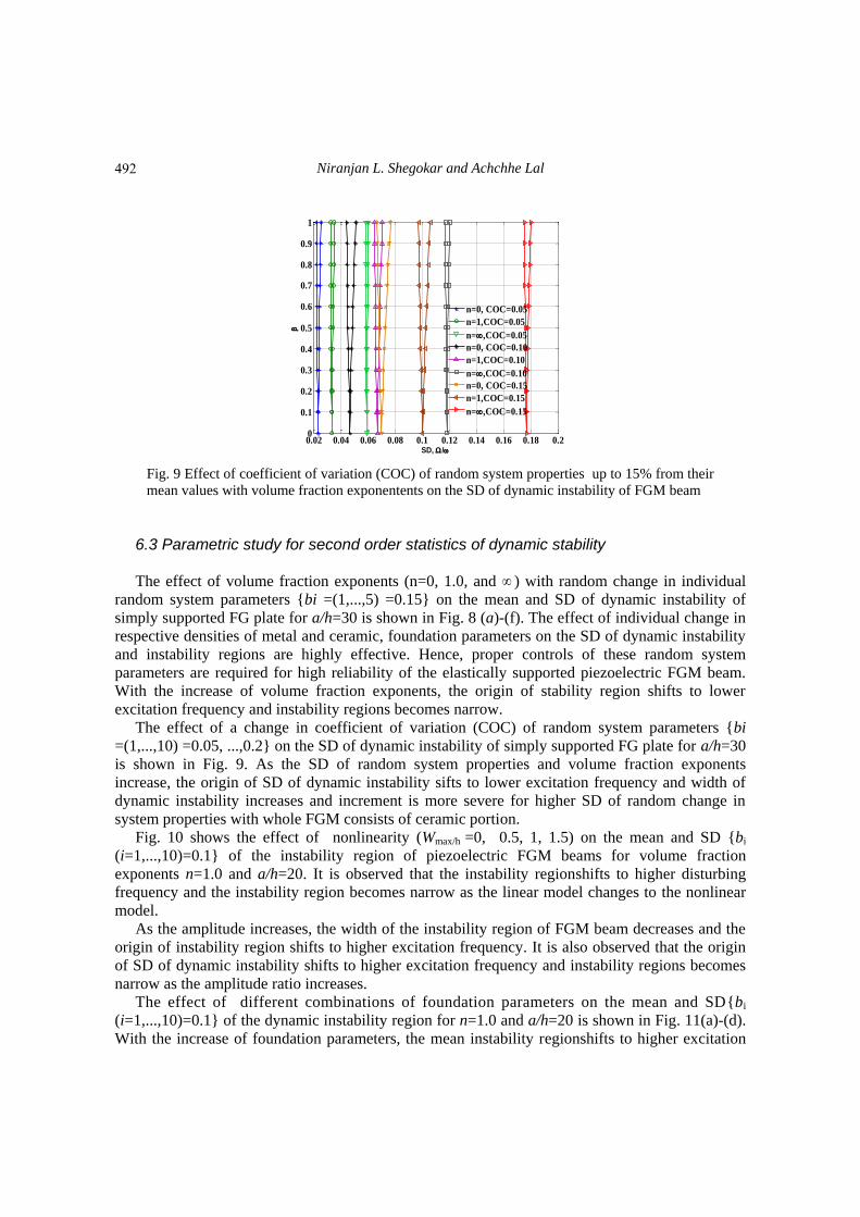
Fig. 9 Effect of coefficient of variation (COC) of random system properties up to 15% from their
mean values with volume fraction exponentents on the SD of dynamic instability of FGM beam
6.3 Parametric study for second order statistics of dynamic stability The effect of volume fraction exponents (n=0, 1.0, and ) with random change in individual
random system parameters {bi =(1,...,5) =0.15} on the mean and SD of dynamic instability of
simply supported FG plate for a/h=30 is shown in Fig. 8 (a)-(f). The effect of individual change in
respective densities of metal and ceramic, foundation parameters on the SD of dynamic instability
and instability regions are highly effective. Hence, proper controls of these random system
parameters are required for high reliability of the elastically supported piezoelectric FGM beam.
With the increase of volume fraction exponents, the origin of stability region shifts to lower
excitation frequency and instability regions becomes narrow.
The effect of a change in coefficient of variation (COC) of random system parameters {bi
=(1,...,10) =0.05, ...,0.2} on the SD of dynamic instability of simply supported FG plate for a/h=30
is shown in Fig. 9. As the SD of random system properties and volume fraction exponents
increase, the origin of SD of dynamic instability sifts to lower excitation frequency and width of
dynamic instability increases and increment is more severe for higher SD of random change in
system properties with whole FGM consists of ceramic portion.
Fig. 10 shows the effect of nonlinearity (Wmax/h =0, 0.5, 1, 1.5) on the mean and SD {bi
(i=1,...,10)=0.1} of the instability region of piezoelectric FGM beams for volume fraction
exponents n=1.0 and a/h=20. It is observed that the instability regionshifts to higher disturbing
frequency and the instability region becomes narrow as the linear model changes to the nonlinear
model.
As the amplitude increases, the width of the instability region of FGM beam decreases and the
origin of instability region shifts to higher excitation frequency. It is also observed that the origin
of SD of dynamic instability shifts to higher excitation frequency and instability regions becomes
narrow as the amplitude ratio increases.
The effect of different combinations of foundation parameters on the mean and SD{bi
(i=1,...,10)=0.1} of the dynamic instability region for n=1.0 and a/h=20 is shown in Fig. 11(a)-(d).
With the increase of foundation parameters, the mean instability regionshifts to higher excitation
0.02 0.04 0.06 0.08 0.1 0.12 0.14 0.16 0.18 0.20
0.1
0.2
0.3
0.4
0.5
0.6
0.7
0.8
0.9
1
SD, /
n=0, COC=0.05
n=1,COC=0.05
n=,COC=0.05
n=0, COC=0.10
n=1,COC=0.10
n=,COC=0.10
n=0, COC=0.15
n=1,COC=0.15
n=,COC=0.15
492

Stochastic dynamic instability response of piezoelectric functionally graded beams...
(a) mean (b) SD
Fig. 10 Effect of theamplitude ratios (Wmax/h =0, 0.5, 1, 1.5) on the dynamic instability region of
piezoelectric FGM beams with random material properties.
(a) mean (b) SD
(c) mean (d) SD
Fig. 11 Effect of thefoundation parameters on the dynamic instability of piezoelectric FGM beam
2.5 3 3.5 4 4.50
0.1
0.2
0.3
0.4
0.5
0.6
0.7
0.8
0.9
1
Mean, /
Wmax
/h=0
Wmax
/h=0.5
Wmax
/h=1
Wmax
/h=1.5
0.05 0.055 0.06 0.065 0.07 0.075 0.080
0.1
0.2
0.3
0.4
0.5
0.6
0.7
0.8
0.9
1
SD, /
Wmax
/h=0
Wmax
/h=0.5
Wmax
/h=1
Wmax
/h=1.5
2.2 2.4 2.6 2.8 3 3.2 3.4 3.6 3.80
0.2
0.4
0.6
0.8
1
Mean, /
Without Foundation
k1=50, k
2=5, k
3=100
k1=100, k
2=10, k
3=100
0 0.01 0.02 0.03 0.04 0.050
0.2
0.4
0.6
0.8
1
SD, /
Without Foundation
k1=50, k
2=5, k
3=100
k1=100, k
2=10, k
3=100
2.6 2.8 3 3.2 3.4 3.6 3.8 4 4.20
0.1
0.2
0.3
0.4
0.5
0.6
0.7
0.8
0.9
1
Mean, /
k1=50, k
2=5, k
3=100
k1=100, k
2=5, k
3=100
k1=100, k
2=10, k
3=100
0.06 0.07 0.08 0.09 0.1 0.11 0.12 0.13 0.14 0.150
0.1
0.2
0.3
0.4
0.5
0.6
0.7
0.8
0.9
1
SD, /
k1=50, k
2=5, k
3=100
k1=100, k
2=5, k
3=100
k1=100, k
2=10, k
3=100
493

Niranjan L. Shegokar and Achchhe Lal
(a) mean (b) SD
Fig. 12 Effect of thevolume fraction exponents on the dynamic instability region of piezoelectric FGM
beam
(a) mean (b) SD
Fig. 13 Effect of thetemperature variation on top surface on the dynamic instability region of FGM beam
frequency and width of the instability regions becomes narrow. Further, among the given different
combination of foundation parameters, the effect of shear foundation on the dynamic instability
ishighest as compared to other foundation parameters. This is due to the fact that the foundation
parameters increase the effective stiffness matrix that makes the beam more stable. The effect of
the shear foundation parameteris most dominant to increase the stability and possibilities of
resonance conditions.
Fig. 12 (a)-(b) examines the effect of volume fraction exponents (n=0, 1.0, and 2) on the mean
and SD {bi (i=1,...,10)=0.1} of dynamic instability of FGM beams with a/h=20 (foundation
parameters??). With the increase of volume fraction exponents, the origin of mean dynamic
instability shifts to higher frequency excitation and the instability region becomes wider and
maximum when beam is composed of metal only. Although, SD of dynamic instability sifted to
higher excitation frequency and thecorresponding region becomes narrow.
Fig. 13 (a)-(b) shows the effect of temperature variation on top surface of beam (Tc=500 K, 700
2.7 2.8 2.9 3 3.1 3.2 3.3 3.40
0.1
0.2
0.3
0.4
0.5
0.6
0.7
0.8
0.9
1
Mean, /
n=0.5
n=1
n=2
0.055 0.06 0.065 0.07 0.075 0.080
0.1
0.2
0.3
0.4
0.5
0.6
0.7
0.8
0.9
1
SD, /
n=0.5
n=1
n=2.0
2.7 2.8 2.9 3 3.1 3.2 3.3 3.40
0.1
0.2
0.3
0.4
0.5
0.6
0.7
0.8
0.9
1
Mean, /
Tc=500 K
Tc=700 K
Tc=900 K
0.064 0.065 0.066 0.067 0.068 0.069 0.07 0.071 0.072 0.0730
0.1
0.2
0.3
0.4
0.5
0.6
0.7
0.8
0.9
1
SD, /
Tc=500 K
Tc=700 K
Tc=900 K
494

Stochastic dynamic instability response of piezoelectric functionally graded beams...
(a) mean (b) SD
Fig. 14 Effect of theposition of piezoelectric layer on the dynamic instability of piezoelectric FGM beams
K, and 900 K) with random change in system properties {bi (i=1,...,10)=0.1} on the mean and SD
instability of piezoelectric FGMs beam resting with elastic foundation for n=1 and a/h=20. With
the increase of top surface temperature, the mean instability shifts to higher excitation and
boundary region becomes wider. Although, origin of SD dynamic stability also shifted to higher
excitation frequency and the instability region becomes narrow.
The effect of position of piezoelectric layers with random system properties{bi
(i=1,...,10)=0.1}on the mean and SD of dynamic instability for simply supported FGM beams for
volume fraction index n=0.5 and a/h=20 is shown in Fig. 14 (a)-(b). With the attachment of
piezoelectric layers, the origin of mean dynamic stability shifted to lower excitation frequency and
instability region becomes wider. Although, The origin of SD of dynamic instability also shifts to
lower excitation frequency and instability region becomes narrow.
The appearance of beats the phenomenon displacement response of simply supported FGM
beam supported by elastic foundationis shown in Fig . 15 (a)-(d). The beat phenomena
(a) without foundation, n=0.5 (b) n=0.5
Fig. 15 Beat phenomena displacement response subjected to a periodic loading in unstable region for a/h=30
2.7 2.8 2.9 3 3.1 3.2 3.3 3.4 3.50
0.2
0.4
0.6
0.8
1
Mean, /
FGM
P-FGM-P
P-FGM
0.054 0.056 0.058 0.06 0.062 0.064 0.066 0.068 0.070
0.2
0.4
0.6
0.8
1
SD, /
FGM
P-FGM-P
P-FGM
0 2 4 6 8 10 12-4
-3
-2
-1
0
1
2
3
4x 10
-4
dis
pla
cem
en
t (m
)
Time (s)
=200 rad/sn=0.5, =0, =0.8
0 2 4 6 8 10 12-3
-2
-1
0
1
2
3
4x 10
-4
dis
pla
cem
en
t (m
)
Time (s)
=200 rad/s
n=0.5, =0, =0.8k
1=100, k
2=5, k
3=100
495

Niranjan L. Shegokar and Achchhe Lal
(c) n=1 (d) n=2
Fig. 15 Continued
(a) mean dynamic displacement (b) SD of dynamic displacement
(c) mean dynamic displacement (d) SD of dynamic displacement
Fig. 16 Effect of foundation parameteron mean and SD of dynamic displacement for a/h=30
0 2 4 6 8 10 12-3
-2
-1
0
1
2
3
4x 10
-4
dis
pla
cem
en
t (m
)
Time (s)
=200 rad/sn=1, =0, =0.8k
1=100, k
2=5, k
3=100
0 2 4 6 8 10 12-4
-3
-2
-1
0
1
2
3
4x 10
-4
dis
pla
cem
en
t (m
)
Time (s)
=200 rad/s
n=2, =0, =0.8k
1=100, k
2=5, k
3=100
0 2 4 6 8 10 12-1.5
-1
-0.5
0
0.5
1
1.5x 10
-4
dis
pla
cem
en
t (m
)
Time (s)
=200 rad/sn=0.5, =0, =0.5k
1=100, k
2=5, k
3=100
0 2 4 6 8 10 120
0.2
0.4
0.6
0.8
1
1.2x 10
-3
SD
(m)
Time (s)
=200 rad/sn=0.5, =0, =0.5k
1=100, k
2=5, k
3=100
0 2 4 6 8 10 12-1.5
-1
-0.5
0
0.5
1
1.5x 10
-4
dis
pla
cem
en
t (m
)
Time (s)
=200 rad/sn=0.5, =0, =0.5
0 2 4 6 8 10 120
0.2
0.4
0.6
0.8
1
1.2
1.4
1.6x 10
-3
SD
(m)
Time (s)
=200 rad/sn=0.5, =0, =0.5
496

Stochastic dynamic instability response of piezoelectric functionally graded beams...
(a) mean dynamic displacement for n=0.5 (b) SD of dynamic displacement for n=0.5
(c) mean dynamic displacement for n=2 (d) SD for n=2
Fig. 17 Effect of volume fraction exponents on mean and SD of dynamic displacement
displacement response of a simply supported FGM beam supported with and without elastic
foundation subjected to a periodic in-plane loading in the unstable region is examined. It is
observed that the dynamic displacement of beam resting on elastic foundation is not much
significant as compared to without foundation. The displacement response shows an increasing
order due to the compressive periodic in-plane load under higher dynamic loading factor. The
dynamic load parameters carrying the structure in unstable state is unreliable and hazardous and
causes the structural failure. For this reason structure designer try to eliminate the instability of the
structure with load control, nonlinearity and damping behavior of the structure.
Fig. 16 (a)-(d) shows the dynamic nonlinear displacement response of a simply supported
piezoelectric FGM beam subjected to a periodic loading in unstable region for the beam supported
with and without foundation for β=0.5, α=0.0, n=1, a/h=20. ω=200 rad/s. The beam supported by
elastic foundation shows higher dynamic displacement as compared to beam without supported by
elastic foundation. This is due to the fact that the foundation parameters increase the effective
stiffness matrix of the beam which lower the bending resistance and beam becomes more stable.
Fig. 17 (a)-(d) shows the effect of volume fraction exponents on the nonlinear mean and SD of
dynamic deflection with random change in {bi (i=1,...,10)=0.1} for β=0.5, α=0.5 and Wmax/h=0.5.
0 2 4 6 8 10 12-1.5
-1
-0.5
0
0.5
1
1.5x 10
-4
dis
pla
cem
en
t (m
)
Time (s)
n=0.5, a/h=25
=0, =0.5
0 2 4 6 8 10 120
0.5
1
1.5
2
2.5
3
3.5
4
4.5
5x 10
-5
SD
(m)
Time (s)
n=0.5, a/h=25
=0, =0.5
0 2 4 6 8 10 12-1.5
-1
-0.5
0
0.5
1
1.5x 10
-4
dis
pla
cem
en
t (m
)
Time (s)
n=2, a/h=25
=0, =0.5
0 2 4 6 8 10 120
1
2
x 10-4
SD
(m)
Time (s)
n=2, a/h=25
=0, =0.5
497

Niranjan L. Shegokar and Achchhe Lal
The effect of volume fraction exponent on mean dynamic displacement of beam is much
significant as compared to higher volume fraction exponent. However, change of SD of dynamic
deflection for a higher volume fraction exponent is higher than the lower volume fraction
exponent. It is due to fact that at lower volume fraction exponent, the FGM beam contains a higher
volume of ceramic portion.
7. Conclusions
In the FGM materials, as the amount of metal portion increases, the origin of instability regions
becomes narrow and shifts to lower excitation frequency. Therefore, more amount of metal
portions should be taken into consideration for stability of the structures.
With the presence of randomness at various levels, the origin of instability regions shifts to
lower excitation frequency and the width of instability region increases. Hence, analysis of
randomness of various randomness levels gives a more realistic picture of the parameters those are
involved in safety in final design. Hence, the quantification of randomness is extremely important.
Volume fraction exponents decrease the stability of the beam and increases the possibilities of
resonance conditions.
As the amplitude ratio increase, the mean of dynamic instability shifts to higher excitation
frequency and origin of dynamic instability regions becomes wider. Hence, the geometrical
nonlinearity effect provides lower mean stability to the structures, however, vice versa for SD of
dynamic stability.
Beam supported by elastic foundations provides higher mean dynamic stability and possibilities
of higher resonance conditions. However, the SD of dynamic instability increases the possibilities
of resonance conditions and lowers the dynamic stability. The effect of the shear foundation
parameter is highly dominant as compared to linear and nonlinear Winkler foundation parameters.
Hence, proper control of shear foundation is highly desirable for high safety of the elastically
supported FGM beam.
The increments in temperature change decrease the mean stability of the beam and increases
the possibilities ofresonanceconditions. However, SD of dynamic stability decreases the stability
of beam and increases the possibilities of resonance conditions. Hence, it is concluded that
temperature increments play an important role to decrease the stability and increasesthe
possibilities of resonancethe structures.The presence of piezoelectric layers decreases the mean
and SD of stability of the beam and increases the possibility of resonance condition. The beat
phenomenon of elastically supported FGM beam by changing the foundation parameter and
volume fraction exponents is not so sensitive. However, the mean and SD of dynamic central
deflection of FGM beam supported by elastic foundation are highly sensitive by increasing the
foundation parameter and volume fraction exponents.
References Abbas, B.A.H. and Thomas, J. (1978), “Dynamic stability of Timoshenko beams resting on an elastic
foundation”, J. Sound Vib., 60(1), 33-44.
Ahuja, R. and Duffield, R.C. (1975), “Parametric instability of variable cross-section beams resting on an
elastic foundation”, J. Sound Vib., 39(2), 159-174.
498

Stochastic dynamic instability response of piezoelectric functionally graded beams...
Baldinger, M., Belyaev, A.K. and Irschik, H. (2000), “Principal and second instability regions of shear-
deformable polygonal plates”, Comput. Mech., 26, 288-94.
Bert, C.W. and Birman, V. (1987), “Dynamic instability of shear deformable antisymmetric angle-ply
plates”, Int. J. Solid. Struct., 23(7), 1053-61.
Bolotin, V.V. (1964), The Dynamic Stability of Elastic Systems, Holden- Day, Oakland, Calif.
Chang, T.P. and Chang, H.C. (1994), “Stochastic dynamic finite element analysis of a non uniform beam”,
Int. J. Solid Struct., 31(5), 587-597.
Chattopadhyay, A. and Radu, A.G. (2000), “Dynamic instability of composite laminates using a higher order
theory”, Comput. Struct., 77, 453-60.
Chen, L.W. and Yang, J.Y. (1990), “Dynamic stability of laminated composite plates by the finite element
method”, Comput. Struct., 36, 845-51.
Darabi, M., Darvizeh, M. and Darvizeh, A. (2007), “Non-linear analysis of dynamic stability for functionally
graded cylindrical shells under periodic axial loading”, Compos. Struct., 83(2), 201-11.
Datta, P.K. and Chakraborty S. (1982), “Parametric instability of tapered beam by finite element method”, J.
Mech. Eng., 24(4), 205.
Dey, S.S. (1979), “Finite element method for random response of structures due to stochastic excitation”,
Comput. Meth. Appl. Mech. Eng., 20(2), 173-194.
Evan-Iwanowski, R.M. (1965), “The parametric response of structures”, Appl. Mech. Rev., 18, 699-702.
Fallah, A. and Aghdam, M.M. (2011), “Nonlinear free vibration and post buckling analysis of functionally
graded beams on nonlinear elastic foundation”, Eur. J. Mech. A/Solid., 30, 571-583.
Fu, Y., Wang, J. and Mao, Y. (2012), “Nonlinear analysis of bucklng, free vibration and dynamic stability
for the piezoelectric functionally graded beams in thermal environment”, Appl. Math. Model., 36(9),
4324-4340.
Ganapathi, M., Boisse P. and Solaut D. (1999), “Non-linear dynamic stability analysis of composite
laminates under periodic in-plane compressive loads”, Int. J. Numer. Meth. Eng., 46, 943-956.
Ganapathi, M., Varadan, T.K. and Balamurugan, V. (1994), “Dynamic instability of laminated composite
curved panels using finite element method”, Compos. Struct., 53, 335-42.
Giuseppe, Q. (2011), “Finite element analysis with uncertain probabilities”, Comput. Meth. Appl. Mech.
Eng., 200(1-4), 114-129.
Heyliger, P.R. and Reddy, J.N. (1988), “A higher order beam finite element for bending and vibration
problems”, J. Sound Vib., 126(2), 309-326.
Hu, H.T. and Tzeng, W.L. (2000), “Buckling analysis of skew laminate plates subjected to uniaxial inplane
loads”, Thin Wall Struct., 38(1), 53-77.
Ibrahim, R.A. (1987), “Structural dynamics with parameter uncertainties”, Appl. Mech. Rev., 40(3), 309-328.
Iwankiewicz, R. and Nielsen, S.R.K. (1999), Advanced Method In Stochastic Dynamics of Nonlinear
Systems, Aalborg University Press.
Jagtap, K.R., Lal, A. and Singh, B.N. (2011), “Stochastic nonlinear free vibration analysis of elastically
supported functionally graded materials plate with system randomness in thermal environment”, Compo.
Struct., 93(12), 3185-3199.
Jagtap, K.R., Lal, A. and Singh, B.N. (2013), “Thermomechanical elastic postbuckling of functionally
graded materials plate with random system propertie”, Int. J. Comp. Meth. Eng. Sci. Mech., 14, 175-194.
Kapania, R.K. and Park, S. (1996), “Nonlinear transient response and its sensitivity using finite elements in
time”, Comput. Mech., 17(5), 306-317.
Kareem, A. and Sun W.J. (1990), “Dynamic response of structures with uncertain damping”, Eng. Struct.,
12(1), 2-8.
Ke, L.L. and Wang, Y.S. (2011), “Size effect on dynamic stability of functionally graded microbeams based
on a modified couple stress theory”, Compos. Struct., 93(2), 342-350.
Kiani, Y. and Eslami, M.R. (2010), “Thermal buckling analysis of functionally graded material beams”, Int.
J. Mech. Mater. Des., 6, 229-238.
Kiani, Y. and Eslami, M.R. (2013), “Thermomechanical buckling of temperature dependent FGM beams”,
Lat. Am. J. Solid. Struct., 10, 223-246.
499

Niranjan L. Shegokar and Achchhe Lal
Kleiber, M. and Hien, T.D. (1992), The Stochastic Finite Element Method, John Wiley & Sons.
Lal, A., Jagtap, K.R. and Singh, B.N. (2013), “Post buckling response of functionally graded materials plate
subjected to mechanical and thermal loadings with random material properties”, Appl. Math. Model.,
37(7), 2900-2920.
Lal, A., Kulkarni, N.M. and Singh, B.N. (2015), “Stochastic thermal post buckling response of elastically
supported laminated piezoelectric composite plate using micromechanical approach”, Curv. Layer.
Struct., 2, 331-350.
Lal, A., Saidane, N. and Singh, B.N. (2012a), “Stochastic hygrothermoelectromechanical loaded post
buckling analysis of piezoelectric laminated cylindrical shell panels”, Smart Struct. Syst., 9(6), 505-534.
Lal, A., Singh, H. and Shegokar, N.L. (2012b), “FEM model for stochastic mechanical and thermal
postbuckling response of functionally graded material plates applied to panels with circular and square
holes having material randomness”, Int. J. Mech. Sci., 62(1), 18-33.
Liao, C.L. and Cheng, C.R. (1994), “Dynamic stability of stiffened laminated composite plates and shells
subjected to in-plane pulsating forces”, Int. J. Numer. Meth. Eng., 37, 4167-83.
Liu, W.K., Belytschko, T. and Mani, A. (1986), “Probabilistic finite elements for nonlinear structural
dynamics”, Comput. Meth. Appl. Mech. Eng., 56(1), 61-81.
Mohanty, S.C., Dash, R.R. and Rout, T. (2011), “Parametric instability of a functionally graded Timoshenko
beam on Winkler’s elastic foundation”, Nucl. Eng. Des., 241(8), 2698- 2715.
Moorthy, J. and Reddy, J.N. (1990), “Parametric Instability of laminated composite plates with transverse
shear deformation”, Int. J. Solid. Struct., 26, 801-811.
Namachchivaya, N. and Lin, Y.K. (2003), Nonlinear Stochastic Dynamics, Solid Mechanics and Its
Applications, Kluwar Academic publishers, Dordrecht.
Nayfeh, A. (1993), Introduction to Perturbation Techniques, Wiley-Inter science.
Ng, T.Y., Lam, K.Y., Liew, K.M. and Reddy, J.N. (2001), “Dynamic stability analysis of functionally
graded cylindrical shells under periodic axial loading”, Int. J. Solid. Struct., 38(8), 1295-1309.
Nigam, N.C. and Narayanan, S. (1994), Applications of Random Vibrations, Narosa, New Delhi.
Onkar, A.K. and Yadav, D. (2005), “Forced nonlinear vibration of laminated composite plates with random
material properties”, Compos. Struct., 70(3), 334-342.
Patel, B.P., Singh, S. and Nath, Y. (2006), “Stability and nonlinear dynamic behaviour of cross-ply
laminated heated cylindrical shells”, Lat. Am. J. Solid. Struct., 3, 245-26.
Pradyumna, S. and Bandyopadhyay, J.N. (2010), “Dynamic instability of functionally graded shells using
higher-order theory”, J. Eng. Mech., 136(5), 551-561.
Raj, B.N., Iyengar, N.G.R. and Yadav, D. (1998), “Response of composite plates with random material
properties using Monte Carlo Simulation”, Adv. Compos. Mater., 7(3), 219-237.
Ren, Y.J., Elishakoff, I. and Shinozuka, M. (1997), “Finite elelemt method for stochastic beams based on
variational principles”, J. Appl. Mech., 64(3), 664-669.
Rollot, O. and Elishakoff, I. (2003), “Large variation finite element method for beams with stochastic
stiffness”, Chao. Solit. Fract., 17(4), 749-779.
Sahu, S.K. and Datta, P.K. (2007), “Research advances in the dynamic stability behavior of plates and
shells: 1987-2005 Part I: conservative system”, Appl. Mech. Rev., 60, 65-75.
Shaker, A., Abdelrahman, W., Tawfik, M. and Sadek, E. (2008), “Stochastic finite element analysis of the
free vibration of laminated composite plates”, Comput. Mech., 41, 493-501.
Shegokar, N.L. and Lal, A. (2013a), “Stochastic nonlinear bending response of piezoelectric functionally
graded beam subjected to thermoelectromechanical loadings with random material properties”, Compos.
Struct., 100, 17-33.
Shegokar, N.L. and Lal, A. (2013b), “Stochastic finite element nonlinear free vibration analysis of
piezoelectric functionally graded beam subjected to thermo-piezoelectric loadings with material
uncertainties”, Meccanica, 49, 1039-1068.
Shegokar, N.L. and Lal, A. (2014), “Thermoelectromechanically induced stochastic post buckling response
of piezoelectric functionally graded beam”, Int. J. Mech. Mater. Des., 10, 329-349.
Shinozuka, M. and Astill, C.J. (1972), “Random eigenvalue problems in structural analysis”, AIAA J., 10(4),
500

Stochastic dynamic instability response of piezoelectric functionally graded beams...
456-462.
Singha, M.K., Ramachandra, L.S. and Bandyopadhyay, J.N. (2001), “Stability and strength of composite
skew plates under thermomechanical loads”, Am. Inst. Aeronaut. J., 39(8), 1618-23.
Srinivasan, R.S. and Chellapandi, P. (1986), “Dynamic stability of rectangular laminated composite plates”,
Comput. Struct., 24(2), 233-8.
Stefanou, G. (2009), “The stochastic finite element method: Past, present and future, Engineering”, Comput.
Meth. Appl. Mech. Eng., 198(9), 1031-1051.
Vanmarcke, E. and Grigoriu, M. (1983), “Stochastic finite element analysis of simple beams”, J. Eng.
Mech., 109(5), 1203-1214.
Wang, S. and Dawe, D.J. (2002), “Dynamic instability of composite laminated rectangular plates and
prismatic plate structures”, Comput. Meth. Appl. Mech. Eng., 191, 1791-826.
Wu, L., Wang, H.J. and Wang, D.B. (2007), “Dynamic stability analysis of FGM plates by the moving least
squares differential quadraturemethod”, Compos. Struct., 77(3), 383-394.
Yang, J., Liew, K.M. and Kitipornchai, S. (2004), “Dynamic stability of laminated FGM plates based on
higher-order shear deformation theory”, Comput. Mech., 33(4), 305-315.
Yang, J., Liew, K.M. and Kitipornchai, S. (2005), “Stochastic analysis of compositionally graded plates with
system randomness under static loading”, Int. J. Mech. Sci., 47(10), 1519-1541.
Young, T.H. and Chen, F.Y. (1994), “Stability of skew plates subjected to aerodynamic and in-plane
forces”, J. Sound Vib., 171(5), 603-15.
Zhao, L. and Chen, Q. (1998), “A dynamic stochastic finite element method based on dynamic constraint
mode”, Comput. Meth. Appl. Mech. Eng., 161(3-4), 245-25.
Zhu, J., Chen, C., Shen, Y. and Wang, S. (2005), “Dynamic stability of functionally graded piezoelectric
circular cylindrical shells”, Mater. Lett., 59(4), 477-85.
EC
501

Niranjan L. Shegokar and Achchhe Lal
Appendix
3
2
1 0 0
0 0 0 1
z z
z
,
4 2 4 2
1 1 1 1
4 4 4 4
0 0 0 0 0 0
0 0 0 0 0 0
0 0 0 0
0 0 0 0
0 0 3 3 0 0 3 3
x x
x x
x x x x
x x
LC C C C
C C C C
C C C C
(A-1)
11 11 11
11 11 11/2
11 11 11
/2
55 55
55 55
0 0
0 0
0 0
0 0 0
0 0 0
hT
h
A B E
B D F
D T Q T dz E F H
A D
D F
(A-2a)
/ 2
2 3 4 6
11 11 11 11 11 11 11/ 2
, , , , , 1, , , , ,h
hA B D E F H Q z z z z z dz
and
/ 22 4
55 55 55 55/ 2
, , 1, ,h
hA D F Q z z dz
11 11
11 11/2
1 11 11
/222 22 22
22 22 22
0 0 0
0 0 0
0 0 0
0 0
0 0
hT
h
M N
N P
D T e T dz P R
M N P
N P R
(A-2b)
/2 /2
2 3 2 3
11, 11, 11, 11 15 , , , 22, 22, 22, 22 31 , , ,
/2 /2
1 1
h h
h h
M N P R e z z z dz M N P R e z z z dz
11 11 11
/2 11 11 11
2 11 11 11
/2
22 22
22 22
0 0
0 0
0 0
0 0 0
0 0 0
p
p
h
h
S T U
T U V
D T T dz U V W
S T
T U
(A-2c)
/2 /2
2 3 4 2
11, 11, 11, 11, 11 11 , , , , 22, 22, 22 33 , ,
/2 /2
1 1
h h
h h
S T U V W k z z z z dz S T U k z z dz
,
11 11 11 11 11 11
3 4 3 5 6 7 6
55 55 55 22 22 22
0 0 0 0 0 0, , , ,
0 0 0 0 0 0
T
T TA B E A M ND D D D D D D
A D A M N P
(A-3)
502