Aboveground biomass and leaf area index (LAI) mapping for Niassa Reserve, northern Mozambique
Upload
independentCategory
view
5download
0
UL 142
ISBN 1-55989-385-0
Steel Aboveground Tanks forFlammable and CombustibleLiquids


July 22, 1998 – UL 142 tr1
Underwriters Laboratories Inc. (UL)333 Pfingsten RoadNorthbrook, IL 60062-2096
UL Standard for Safety forSteel Aboveground Tanks for Flammable and Combustible Liquids, UL 142
Seventh Edition, Dated April 1, 1993
Revisions: This Standard contains revisions through and including July 22, 1998.
A change is indicated by a note following the affected item. The note is preceded and followed by an asterisk.
The new and revised requirements are substantially in accordance with UL's Bulletin on this subject dated July 22, 1998.The bulletin is now obsolete and may be discarded.
The revisions dated July 22, 1998 include a reprinted title page (page 1) for this Standard.
As indicated on the title page (page 1), this UL Standard for Safety has been adopted by the Department of Defense.
The master for this Standard at UL's Northbrook Office is the official document insofar as it relates to a UL service andthe compliance of a product with respect to the requirements for that product and service, or if there are questionsregarding the accuracy of this Standard.
UL's Standards for Safety are copyrighted by UL. Neither a printed copy of a Standard, nor the distribution diskette fora Standard-on-Diskette and the file for the Standard on the distribution diskette should be altered in any way. All of UL'sStandards and all copyrights, ownerships, and rights regarding those Standards shall remain the sole and exclusiveproperty of UL.
All rights reserved. No part of this publication may be reproduced, stored in a retrieval system, or transmitted in any formby any means, electronic, mechanical photocopying, recording, or otherwise without prior permission of UL.
Revisions of UL Standards for Safety are issued from time to time. A UL Standard for Safety is current only if itincorporates the most recently adopted revisions.
UL provides this Standard "as is" without warranty of any kind, either expressed or implied, including but not limited to,the implied warranties of merchantability or fitness for any purpose.
In no event will UL be liable for any special, incidental, consequential, indirect or similar damages, including loss ofprofits, lost savings, loss of data, or any other damages arising out of the use of or the inability to use this Standard, evenif UL or an authorized UL representative has been advised of the possibility of such damage. In no event shall UL'sliability for any damage ever exceed the price paid for this Standard, regardless of the form of the claim.
UL will attempt to answer support requests concerning WordPerfect, Envoy, and Standards-on-Diskette. However, thissupport service is offered on a reasonable efforts basis only, and UL may not be able to resolve every support request.UL supports a Standards-on-Diskette only if it is used under the conditions and operating systems for which it isintended. UL’s support policies may change from time-to-time without notification.
UL reserves the right to change the format, presentation, file types and formats, delivery methods and formats, and thelike of both its printed and electronic Standards without prior notice.

tr2 July 22, 1998 – UL 142
Standards-on-Diskette purchasers agree to defend, indemnify, and hold UL harmless from and against any loss,expense, liability, damage, claim, or judgement (including reasonable attorney's fees) resulting from any error ordeviation introduced while purchaser is storing a Standard-on-Diskette on the purchaser's computer system.
If a single-user version Standards-on-Diskette was purchased, one copy of this Standard may be stored on the harddisk of a single personal computer, or on a single LAN file-server or the permanent storage device of a multiple-usercomputer in such a manner that this Standard may only be accessed by one user at a time and for which there is nopossibility of multiple concurrent access. The original distribution diskette should be stored in a safe place.
If a multiple-user version Standards-on-Diskette was purchased, one copy of the Standard may be stored on a singleLAN file-server, or on the permanent storage device of a multiple-user computer. The number of concurrent users shallnot exceed the number of users authorized for the Standards-on-Diskette version. The original distribution disketteshould be stored in a safe place.
Standards-on-Diskette are intended for on-line use, such as for viewing the requirements of a Standard, conducting aword search, and the like. Only one copy of the Standard may be printed from each single-user version of a Standards-on-Diskette. Only one copy of the Standard may be printed for each authorized user of a multiple-user version of aStandards-on-Diskette. An employee of an organization purchasing a Standard-on-Diskette can make a copy of thepage or pages being viewed for their own fair and/or practical internal use. Because of differences in thecomputer/software/printer setup used by UL and those of Standards-on-Diskette purchasers, the printed copy obtainedby a purchaser may not look exactly like the on-line screen view or the printed Standard.
The requirements in this Standard are now in effect, except for those paragraphs, sections, tables, figures, and/or otherelements of the Standard having future effective dates as indicated in the note following the affected item. The priortext for requirements that have been revised and that have a future effective date are located after the Standard, andare preceded by a "SUPERSEDED REQUIREMENTS" notice.
New product submittals made prior to a specified future effective date will be judged under all of the requirements inthis Standard including those requirements with a specified future effective date, unless the applicant specificallyrequests that the product be judged under the current requirements. However, if the applicant elects this option, it shouldbe noted that compliance with all the requirements in this Standard will be required as a condition of continued Listingand Follow-Up Services after the effective date, and understanding of this should be signified in writing.
Copyright 1998 Underwriters Laboratories Inc.
This Standard consists of pages dated as shown in the following checklist:
Page Date
tr1 – tr4 . . . . . . . . . . . . . . . . . . . . . . . . . . . . . . . . . . . . . . . . . . . . . . . . . . . . . . . . . . . . . . . . . . . . . . . . . . . . . July 22, 19981 . . . . . . . . . . . . . . . . . . . . . . . . . . . . . . . . . . . . . . . . . . . . . . . . . . . . . . . . . . . . April 1, 1993 (Reprinted: July 22, 1998)2, 3 . . . . . . . . . . . . . . . . . . . . . . . . . . . . . . . . . . . . . . . . . . . . . . . . . . . . . . . . . . . . . . . . . . . . . . . . . . . . . . . . July 22, 19984 – 10 . . . . . . . . . . . . . . . . . . . . . . . . . . . . . . . . . . . . . . . . . . . . . . . . . . . . . . . . . . . . . . . . . . . . . . . . . . . . . . . April 1, 199311, 12, 12A, 12B . . . . . . . . . . . . . . . . . . . . . . . . . . . . . . . . . . . . . . . . . . . . . . . . . . . . . . . . . . . . . . . . . . . . . July 22, 199813 . . . . . . . . . . . . . . . . . . . . . . . . . . . . . . . . . . . . . . . . . . . . . . . . . . . . . . . . . . . . . . . . . . . . . . . . . . . . . . . . . . April 1, 199314 . . . . . . . . . . . . . . . . . . . . . . . . . . . . . . . . . . . . . . . . . . . . . . . . . . . . . . . . . . . . . . . . . . . . . . . . . . . . . . . . . July 22, 199815 . . . . . . . . . . . . . . . . . . . . . . . . . . . . . . . . . . . . . . . . . . . . . . . . . . . . . . . . . . . . . . . . . . . . . . . . . . . . . . . . . . April 1, 199316, 17 . . . . . . . . . . . . . . . . . . . . . . . . . . . . . . . . . . . . . . . . . . . . . . . . . . . . . . . . . . . . . . . . . . . . . . . . . . . . . . July 22, 1998

July 22, 1998 – UL 142 tr3
18, 19 . . . . . . . . . . . . . . . . . . . . . . . . . . . . . . . . . . . . . . . . . . . . . . . . . . . . . . . . . . . . . . . . . . . . . . . . . . . . . . . April 1, 199320 – 22, 22A, 22B . . . . . . . . . . . . . . . . . . . . . . . . . . . . . . . . . . . . . . . . . . . . . . . . . . . . . . . . . . . . . . . . . . . . July 22, 199823 . . . . . . . . . . . . . . . . . . . . . . . . . . . . . . . . . . . . . . . . . . . . . . . . . . . . . . . . . . . . . . . . . . . . . . . . . . . . . . . . . . April 1, 199324, 25 . . . . . . . . . . . . . . . . . . . . . . . . . . . . . . . . . . . . . . . . . . . . . . . . . . . . . . . . . . . . . . . . . . . . . . . . . . . . . . July 22, 199826, 27 . . . . . . . . . . . . . . . . . . . . . . . . . . . . . . . . . . . . . . . . . . . . . . . . . . . . . . . . . . . . . . . . . . . . . . . . . . . . . . . April 1, 199328 . . . . . . . . . . . . . . . . . . . . . . . . . . . . . . . . . . . . . . . . . . . . . . . . . . . . . . . . . . . . . . . . . . . . . . . . . . . . . . . . . July 22, 199829 . . . . . . . . . . . . . . . . . . . . . . . . . . . . . . . . . . . . . . . . . . . . . . . . . . . . . . . . . . . . . . . . . . . . . . . . . . . . . . . . . . April 1, 199330, 30A, 30B . . . . . . . . . . . . . . . . . . . . . . . . . . . . . . . . . . . . . . . . . . . . . . . . . . . . . . . . . . . . . . . . . . . . . . . . July 22, 199831 – 40 . . . . . . . . . . . . . . . . . . . . . . . . . . . . . . . . . . . . . . . . . . . . . . . . . . . . . . . . . . . . . . . . . . . . . . . . . . . . . . April 1, 199341, 42, 42A, 42B . . . . . . . . . . . . . . . . . . . . . . . . . . . . . . . . . . . . . . . . . . . . . . . . . . . . . . . . . . . . . . . . . . . . . July 22, 199843 – 45 . . . . . . . . . . . . . . . . . . . . . . . . . . . . . . . . . . . . . . . . . . . . . . . . . . . . . . . . . . . . . . . . . . . . . . . . . . . . . . April 1, 199346, 46A, 46B . . . . . . . . . . . . . . . . . . . . . . . . . . . . . . . . . . . . . . . . . . . . . . . . . . . . . . . . . . . . . . . . . . . . . . . . July 22, 199847 – 50, A1, A2 . . . . . . . . . . . . . . . . . . . . . . . . . . . . . . . . . . . . . . . . . . . . . . . . . . . . . . . . . . . . . . . . . . . . . . . April 1, 1993A3, A4 . . . . . . . . . . . . . . . . . . . . . . . . . . . . . . . . . . . . . . . . . . . . . . . . . . . . . . . . . . . . . . . . . . . . . . . . . . . . . July 22, 1998A5 . . . . . . . . . . . . . . . . . . . . . . . . . . . . . . . . . . . . . . . . . . . . . . . . . . . . . . . . . . . . . . . . . . . . . . . . . . . . . . . . . . April 1, 1993A6, CRG1 – CRG10 . . . . . . . . . . . . . . . . . . . . . . . . . . . . . . . . . . . . . . . . . . . . . . . . . . . . . . . . . . . . . . . . . . July 22, 1998

tr4 July 22, 1998 – UL 142
No Text on This Page

APRIL 1, 1993(Title Page Reprinted: July 22, 1998)
1
UL 142
Standard for
Steel Aboveground Tanks for Flammable and Combustible Liquids
The first edition was titled Horizontal and Vertical Aboveground Storage Tanks forHazardous Liquids. The second edition was titled Aboveground Storage Tanks forHazardous Liquids.
First Edition – December, 1922Second Edition – October, 1953
Third Edition – May, 1968Fourth Edition – December, 1972Fifth Edition – December, 1981Sixth Edition – September, 1987
Seventh Edition
April 1, 1993
An effective date included as a note immediately following certain requirements is oneestablished by Underwriters Laboratories Inc.
The Department of Defense (DoD) has adopted UL 142 on August 11, 1989. Thepublication of revised pages or a new edition of this standard will not invalidate theDoD adoption.
Revisions of this standard will be made by issuing revised or additional pages bearingtheir date of issue. A UL Standard is current only if it incorporates the most recentlyadopted revisions, all of which are itemized on the transmittal notice thataccompanies the latest set of revised requirements.
ISBN 1-55989-385-0
COPYRIGHT © 1981, 1998 UNDERWRITERS LABORATORIES INC.

2 STEEL ABOVEGROUND TANKS FOR FLAMMABLE AND COMBUSTIBLE LIQUIDS – UL 142 JULY 22, 1998
CONTENTS
FOREWORD
INTRODUCTION
1 Scope . . . . . . . . . . . . . . . . . . . . . . . . . . . . . . . . . . . . . . . . . . . . . . . . . . . . . . . . . . . . . . . . . . . . . . . . . . . . . . 52 General . . . . . . . . . . . . . . . . . . . . . . . . . . . . . . . . . . . . . . . . . . . . . . . . . . . . . . . . . . . . . . . . . . . . . . . . . . . . 53 Glossary . . . . . . . . . . . . . . . . . . . . . . . . . . . . . . . . . . . . . . . . . . . . . . . . . . . . . . . . . . . . . . . . . . . . . . . . . . . . 5
CONSTRUCTION – ALL TANKS
4 Capacities and Dimensions . . . . . . . . . . . . . . . . . . . . . . . . . . . . . . . . . . . . . . . . . . . . . . . . . . . . . . . . . . . . . 65 Materials . . . . . . . . . . . . . . . . . . . . . . . . . . . . . . . . . . . . . . . . . . . . . . . . . . . . . . . . . . . . . . . . . . . . . . . . . . . . 66 Joints . . . . . . . . . . . . . . . . . . . . . . . . . . . . . . . . . . . . . . . . . . . . . . . . . . . . . . . . . . . . . . . . . . . . . . . . . . . . . . 77 Tank Connections . . . . . . . . . . . . . . . . . . . . . . . . . . . . . . . . . . . . . . . . . . . . . . . . . . . . . . . . . . . . . . . . . . . 12A8 Venting . . . . . . . . . . . . . . . . . . . . . . . . . . . . . . . . . . . . . . . . . . . . . . . . . . . . . . . . . . . . . . . . . . . . . . . . . . . . 189 Manholes . . . . . . . . . . . . . . . . . . . . . . . . . . . . . . . . . . . . . . . . . . . . . . . . . . . . . . . . . . . . . . . . . . . . . . . . . . 2010 Fill, Drain, and Gauge Openings . . . . . . . . . . . . . . . . . . . . . . . . . . . . . . . . . . . . . . . . . . . . . . . . . . . . . . . 2711 Painting . . . . . . . . . . . . . . . . . . . . . . . . . . . . . . . . . . . . . . . . . . . . . . . . . . . . . . . . . . . . . . . . . . . . . . . . . . 27
PART I – PRIMARY CONTAINMENT TANKS
HORIZONTAL CYLINDRICAL CONSTRUCTIONS
12 General . . . . . . . . . . . . . . . . . . . . . . . . . . . . . . . . . . . . . . . . . . . . . . . . . . . . . . . . . . . . . . . . . . . . . . . . . . 2713 Construction . . . . . . . . . . . . . . . . . . . . . . . . . . . . . . . . . . . . . . . . . . . . . . . . . . . . . . . . . . . . . . . . . . . . . . . 27
VERTICAL CYLINDRICAL CONSTRUCTIONS
14 General . . . . . . . . . . . . . . . . . . . . . . . . . . . . . . . . . . . . . . . . . . . . . . . . . . . . . . . . . . . . . . . . . . . . . . . . . . 3115 Construction . . . . . . . . . . . . . . . . . . . . . . . . . . . . . . . . . . . . . . . . . . . . . . . . . . . . . . . . . . . . . . . . . . . . . . . 31
RECTANGULAR CONSTRUCTIONS
16 General . . . . . . . . . . . . . . . . . . . . . . . . . . . . . . . . . . . . . . . . . . . . . . . . . . . . . . . . . . . . . . . . . . . . . . . . . . 3317 Construction . . . . . . . . . . . . . . . . . . . . . . . . . . . . . . . . . . . . . . . . . . . . . . . . . . . . . . . . . . . . . . . . . . . . . . . 3318 Performance . . . . . . . . . . . . . . . . . . . . . . . . . . . . . . . . . . . . . . . . . . . . . . . . . . . . . . . . . . . . . . . . . . . . . . 34
PART II – SECONDARY CONTAINMENT TANKS
ALL SECONDARY CONTAINMENT TANK CONSTRUCTIONS
19 General . . . . . . . . . . . . . . . . . . . . . . . . . . . . . . . . . . . . . . . . . . . . . . . . . . . . . . . . . . . . . . . . . . . . . . . . . . 34
HORIZONTAL CYLINDRICAL CONSTRUCTIONS
20 General . . . . . . . . . . . . . . . . . . . . . . . . . . . . . . . . . . . . . . . . . . . . . . . . . . . . . . . . . . . . . . . . . . . . . . . . . . 3421 Construction . . . . . . . . . . . . . . . . . . . . . . . . . . . . . . . . . . . . . . . . . . . . . . . . . . . . . . . . . . . . . . . . . . . . . . . 34
VERTICAL CYLINDRICAL CONSTRUCTIONS
22 General . . . . . . . . . . . . . . . . . . . . . . . . . . . . . . . . . . . . . . . . . . . . . . . . . . . . . . . . . . . . . . . . . . . . . . . . . . 3623 Construction . . . . . . . . . . . . . . . . . . . . . . . . . . . . . . . . . . . . . . . . . . . . . . . . . . . . . . . . . . . . . . . . . . . . . . . 36

JULY 22, 1998 STEEL ABOVEGROUND TANKS FOR FLAMMABLE AND COMBUSTIBLE LIQUIDS – UL 142 3
RECTANGULAR CONSTRUCTIONS
24 General . . . . . . . . . . . . . . . . . . . . . . . . . . . . . . . . . . . . . . . . . . . . . . . . . . . . . . . . . . . . . . . . . . . . . . . . . . 3725 Construction . . . . . . . . . . . . . . . . . . . . . . . . . . . . . . . . . . . . . . . . . . . . . . . . . . . . . . . . . . . . . . . . . . . . . . . 3726 Performance Test . . . . . . . . . . . . . . . . . . . . . . . . . . . . . . . . . . . . . . . . . . . . . . . . . . . . . . . . . . . . . . . . . . 38
PART III – DIKED TANKS
27 General . . . . . . . . . . . . . . . . . . . . . . . . . . . . . . . . . . . . . . . . . . . . . . . . . . . . . . . . . . . . . . . . . . . . . . . . . . 3828 Construction . . . . . . . . . . . . . . . . . . . . . . . . . . . . . . . . . . . . . . . . . . . . . . . . . . . . . . . . . . . . . . . . . . . . . . . 3829 Performance Tests . . . . . . . . . . . . . . . . . . . . . . . . . . . . . . . . . . . . . . . . . . . . . . . . . . . . . . . . . . . . . . . . . 39
PART IV – TANK SUPPORTS
30 General . . . . . . . . . . . . . . . . . . . . . . . . . . . . . . . . . . . . . . . . . . . . . . . . . . . . . . . . . . . . . . . . . . . . . . . . . . 4031 Construction . . . . . . . . . . . . . . . . . . . . . . . . . . . . . . . . . . . . . . . . . . . . . . . . . . . . . . . . . . . . . . . . . . . . . . . 4032 Performance Tests . . . . . . . . . . . . . . . . . . . . . . . . . . . . . . . . . . . . . . . . . . . . . . . . . . . . . . . . . . . . . . . . . 42
PART V – TANK ACCESSORIES, COMPONENTS, AND SPECIAL CONSTRUCTIONS
33 General . . . . . . . . . . . . . . . . . . . . . . . . . . . . . . . . . . . . . . . . . . . . . . . . . . . . . . . . . . . . . . . . . . . . . . . . . . 4234 Ladders . . . . . . . . . . . . . . . . . . . . . . . . . . . . . . . . . . . . . . . . . . . . . . . . . . . . . . . . . . . . . . . . . . . . . . . . . . 42A35 Stairs . . . . . . . . . . . . . . . . . . . . . . . . . . . . . . . . . . . . . . . . . . . . . . . . . . . . . . . . . . . . . . . . . . . . . . . . . . . . . 4336 Runways . . . . . . . . . . . . . . . . . . . . . . . . . . . . . . . . . . . . . . . . . . . . . . . . . . . . . . . . . . . . . . . . . . . . . . . . . . 4337 Heating Coils and Hot Wells . . . . . . . . . . . . . . . . . . . . . . . . . . . . . . . . . . . . . . . . . . . . . . . . . . . . . . . . . . 4338 Sumps . . . . . . . . . . . . . . . . . . . . . . . . . . . . . . . . . . . . . . . . . . . . . . . . . . . . . . . . . . . . . . . . . . . . . . . . . . . 44
PERFORMANCE TEST METHODS
39 Tank Leakage Test . . . . . . . . . . . . . . . . . . . . . . . . . . . . . . . . . . . . . . . . . . . . . . . . . . . . . . . . . . . . . . . . . 4440 Hydrostatic Strength Test . . . . . . . . . . . . . . . . . . . . . . . . . . . . . . . . . . . . . . . . . . . . . . . . . . . . . . . . . . . . 4541 Top Load Test . . . . . . . . . . . . . . . . . . . . . . . . . . . . . . . . . . . . . . . . . . . . . . . . . . . . . . . . . . . . . . . . . . . . . 46A42 Buoyancy Test . . . . . . . . . . . . . . . . . . . . . . . . . . . . . . . . . . . . . . . . . . . . . . . . . . . . . . . . . . . . . . . . . . . . . 46A43 Hydrostatic Load Test . . . . . . . . . . . . . . . . . . . . . . . . . . . . . . . . . . . . . . . . . . . . . . . . . . . . . . . . . . . . . . . . 4744 Tank Support Load Test . . . . . . . . . . . . . . . . . . . . . . . . . . . . . . . . . . . . . . . . . . . . . . . . . . . . . . . . . . . . . . 47
MANUFACTURING AND PRODUCTION TESTS
45 Primary and Secondary Containment Tanks . . . . . . . . . . . . . . . . . . . . . . . . . . . . . . . . . . . . . . . . . . . . . . 4746 Diked Tanks . . . . . . . . . . . . . . . . . . . . . . . . . . . . . . . . . . . . . . . . . . . . . . . . . . . . . . . . . . . . . . . . . . . . . . . . 47
MARKINGS
47 General . . . . . . . . . . . . . . . . . . . . . . . . . . . . . . . . . . . . . . . . . . . . . . . . . . . . . . . . . . . . . . . . . . . . . . . . . . . 4848 Marking Elements . . . . . . . . . . . . . . . . . . . . . . . . . . . . . . . . . . . . . . . . . . . . . . . . . . . . . . . . . . . . . . . . . . . 4849 Marking Method and Location . . . . . . . . . . . . . . . . . . . . . . . . . . . . . . . . . . . . . . . . . . . . . . . . . . . . . . . . . . 49
APPENDIX A
Capacity and Wetted Area Tables . . . . . . . . . . . . . . . . . . . . . . . . . . . . . . . . . . . . . . . . . . . . . . . . . . . . . . . . A1
CANADIAN REQUIREMENTS COMPARISON GUIDE
Canadian Requirements Comparison Guide . . . . . . . . . . . . . . . . . . . . . . . . . . . . . . . . . . . . . . . . . . . . . . CRG2

4 STEEL ABOVEGROUND TANKS FOR FLAMMABLE AND COMBUSTIBLE LIQUIDS – UL 142 APRIL 1, 1993
FOREWORD
A. This Standard contains basic requirements for products covered by UnderwritersLaboratories Inc. (UL) under its Follow-Up Service for this category within thelimitations given below and in the Scope section of this Standard. These requirementsare based upon sound engineering principles, research, records of tests and fieldexperience, and an appreciation of the problems of manufacture, installation, and usederived from consultation with and information obtained from manufacturers, users,inspection authorities, and others having specialized experience. They are subject torevision as further experience and investigation may show is necessary or desirable.
B. The observance of the requirements of this Standard by a manufacturer is one ofthe conditions of the continued coverage of the manufacturer's product.
C. A product which complies with the text of this Standard will not necessarily bejudged to comply with the Standard if, when examined and tested, it is found to haveother features which impair the level of safety contemplated by these requirements.
D. A product employing materials or having forms of construction differing from thosedetailed in the requirements of this Standard may be examined and tested accordingto the intent of the requirements and, if found to be substantially equivalent, may bejudged to comply with the Standard.
E. UL, in performing its functions in accordance with its objectives, does not assumeor undertake to discharge any responsibility of the manufacturer or any other party.The opinions and findings of UL represent its professional judgment given with dueconsideration to the necessary limitations of practical operation and state of the artat the time the Standard is processed. UL shall not be responsible to anyone for theuse of or reliance upon this Standard by anyone. UL shall not incur any obligation orliability for damages, including consequential damages, arising out of or in connectionwith the use, interpretation of or reliance upon this Standard.
F. Many tests required by the Standards of UL are inherently hazardous andadequate safeguards for personnel and property shall be employed in conductingsuch tests.

APRIL 1, 1993 STEEL ABOVEGROUND TANKS FOR FLAMMABLE AND COMBUSTIBLE LIQUIDS – UL 142 5
INTRODUCTION
1 ScopeSection 1 effective April 1, 1994
1.1 These requirements cover steel atmospheric tanks intended for aboveground storage of noncorrosive, stableflammable, and combustible liquids that have a specific gravity not exceeding that of water.
1.2 These tanks are intended for installation and use in accordance with the Flammable and Combustible Liquids Code,NFPA 30; the Standard for Installation of Oil Burning Equipment, NFPA 31; and the Automotive and Marine ServiceStation Code, NFPA 30A.
1.3 Tanks covered by these requirements are fabricated, inspected and tested for leakage before shipment from thefactory as completely assembled vessels.
1.4 These requirements do not apply to tanks covered by the Standard for Welded Steel Tanks for Oil Storage,ANSI/API 650; the Specification for Field-Welded Tanks for Storage of Production Liquids, API 12D; and theSpecification for Shop-Welded Tanks for Storage of Production Liquids, API 12F.
1.5 These requirements do not cover seismic loading.
1.6 Geometries or special constructions not specifically covered in these requirements shall be investigated on anindividual basis.
1.7 A product that contains features, characteristics, components, materials, or systems new or different from thosein use when the standard was developed, and that involves a risk of fire, electric shock, or injury to persons shall beevaluated using the appropriate additional component and end-product requirements as determined necessary tomaintain the level of safety for the user of the product as originally anticipated by the intent of this standard.
2 GeneralSection 2 effective April 1, 1994
2.1 Units of Measurement
2.1.1 If a value for measurement is followed by a value in other units in parentheses, the second value may be onlyapproximate. The first stated value is the requirement.
2.2 Undated references
2.2.1 Any undated reference to a code or standard appearing in the requirements of this standard shall be interpretedas referring to the latest edition of that code or standard.
3 GlossarySection 3 effective April 1, 1994
3.1 For the purpose of this standard the following definitions apply.
3.2 ATMOSPHERIC TANK – A storage tank that has been designed to operate at pressures from atmospheric through0.5 psig (3.4 kPa) measured at the top of the tank.

6 STEEL ABOVEGROUND TANKS FOR FLAMMABLE AND COMBUSTIBLE LIQUIDS – UL 142 APRIL 1, 1993
3.3 CLOSED TOP DIKE – A diked aboveground tank with protection on the top of the dike to keep precipitation, debris,or other elements from entering the diked area.
3.4 DIKED ABOVEGROUND TANK FOR FLAMMABLE LIQUIDS – A primary containment aboveground tank withina steel dike intended to contain product resulting from a spill, tank leak, or rupture. Diked aboveground tank typesinclude: closed top dike and open top dike.
3.5 DIKED SECONDARY CONTAINMENT ABOVEGROUND TANK FOR FLAMMABLE LIQUIDS – A secondarycontainment aboveground tank (as defined in 3.8) within a steel dike intended to contain product resulting from a spill,tank leak, or rupture. Diked secondary aboveground tank types include: closed top dike and open top dike.
3.6 OPEN TOP DIKE – A diked aboveground tank in which the dike is open to the elements at the top.
3.7 PRIMARY CONTAINMENT ABOVEGROUND TANK FOR FLAMMABLE LIQUIDS – A steel, single-wall atmospherictank intended for stationary installation having a liquid capacity exceeding 60 U.S. gallons (227 liters) for abovegroundstorage (primary containment) of flammable and combustible liquids. Primary containment aboveground tank typesinclude: horizontal cylindrical, vertical cylindrical, and rectangular.
3.8 SECONDARY CONTAINMENT ABOVEGROUND TANK FOR FLAMMABLE LIQUIDS – A primary containmentaboveground tank contained within a steel secondary containment shell forming an interstitial (annular) space, whichis capable of being monitored for leakage into the space from either the interior or exterior walls. Secondarycontainment aboveground tank types include: horizontal cylindrical, vertical cylindrical, and rectangular.
CONSTRUCTION – ALL TANKS
4 Capacities and DimensionsSection 4 effective April 1, 1994
4.1 Capacities, dimensions, and construction details shall comply with the applicable requirements of this standard.
4.2 Capacities per foot of length or height of cylindrical shells are given in Table A1 of Appendix A for convenience inchecking capacities of tanks of various diameters.
4.3 The total (actual) capacity of a tank shall not be:
a) Less than the rated nominal capacity and
b) More than 110 percent of the rated nominal capacity.
5 MaterialsSection 5 effective April 1, 1994
5.1 A tank shall be constructed of commercial or structural grade carbon steel or stainless steel, as noted in 5.2 and5.3. Only new material shall be used.

APRIL 1, 1993 STEEL ABOVEGROUND TANKS FOR FLAMMABLE AND COMBUSTIBLE LIQUIDS – UL 142 7
5.2 Carbon steel shall be in accordance with (a), (b), or both:
a) Comply with the Specification for Structural Steel, ASTM A36M-91; or Specification for Steel, Carbon (0.15Maximum, Percent), Hot-Rolled Sheet and Strip (Commercial Quality), ASTM A569M-91a; or Specification forSteel, Sheet and Strip, Heavy Thickness Coils, Carbon, Hot-Rolled, ASTM A635M-91a.
b) Have a carbon content of 0.3 percent or less, or a carbon equivalency of 0.53 percent or less, andmechanical strength and welding characteristics at least equivalent to one of the steels specified in (a).
5.3 Stainless steel shall comply with the Specification for Stainless and Heat-Resisting Chromium-Nickel Steel Plate,Sheet, and Strip, ASTM A167-91; or Specification for Heat-Resisting Chromium and Chromium-Nickel Stainless SteelPlate, Sheet, and Strip for Pressure Vessels, ASTM A240-91a.
5.4 The thickness of steel is to be determined by five micrometer readings equally spaced along the edge of the fullpiece as rolled. Thickness is to be determined on the plate or sheet not less than 3/8 inch (9.5 mm) from a cut edgeand not less than 3/4 inch (19.1 mm) from a mill edge.
6 JointsSection 6 effective April 1, 1994
6.1 Joint types for specific tank geometries shall be selected from Table 6.1 and shall comply with the constructionsreferenced in the appropriate Figures.
Table 6.1Joint types
Tank type Figure 6.1 Figure 6.2 Figure 6.3 Figure 6.4 Figure 6.5
Joint types
Shells Heads Bottom Roof Corner
Horizontal cylindrical
(primary and secondary) All All – – –a
Vertical cylindrical
(primary and secondary) All – All All –a
Rectangular
(primary and secondary) All – – – All
Diked
(open and closed top) All – – – All
Shell joint #6 shall not be used on tanks with a diameter greater than 65 inches (1.65 m) unless it is used on the shell of the secondary containmenta
tank where the secondary containment shell is in direct contact with the primary tank.

8 STEEL ABOVEGROUND TANKS FOR FLAMMABLE AND COMBUSTIBLE LIQUIDS – UL 142 APRIL 1, 1993
Figure 6.1Shell joints

APRIL 1, 1993 STEEL ABOVEGROUND TANKS FOR FLAMMABLE AND COMBUSTIBLE LIQUIDS – UL 142 9
Figure 6.2Head joints for horizontal cylindrical tanks

10 STEEL ABOVEGROUND TANKS FOR FLAMMABLE AND COMBUSTIBLE LIQUIDS – UL 142 APRIL 1, 1993
Figure 6.3Bottom joints for vertical cylindrical tanks

JULY 22, 1998 STEEL ABOVEGROUND TANKS FOR FLAMMABLE AND COMBUSTIBLE LIQUIDS – UL 142 11
Figure 6.4Roof joints for vertical cylindrical tanks
Unless otherwise indicated, all welds are to be full fillet welds, at least 1/8-inch (3.2-mm) radius.*Figure 6.4 revised July 22, 1998*
12 STEEL ABOVEGROUND TANKS FOR FLAMMABLE AND COMBUSTIBLE LIQUIDS – UL 142 JULY 22, 1998
Figure 6.5Corner joints
C – Continuous weld.
CF – Shall be continuous full fillet welds.
A – Not less than 1/2 inch (12.7 mm).
*Figure 6.5 revised July 22, 1998*

JULY 22, 1998 STEEL ABOVEGROUND TANKS FOR FLAMMABLE AND COMBUSTIBLE LIQUIDS – UL 142 12A
7 Tank ConnectionsSection 7 effective April 1, 1994
7.1 A tank connection shall be provided for each opening as illustrated in Figure 7.1 or 7.2 by:
a) Welding a steel pipe coupling, threaded steel flange, or standard pipe nipple to the tank or
b) A steel flange welded to a length of pipe that, in turn, is welded to the tank.
The reinforcing plates illustrated in Figure 7.2 are optional.

12B STEEL ABOVEGROUND TANKS FOR FLAMMABLE AND COMBUSTIBLE LIQUIDS – UL 142 JULY 22, 1998
No Text on This Page

APRIL 1, 1993 STEEL ABOVEGROUND TANKS FOR FLAMMABLE AND COMBUSTIBLE LIQUIDS – UL 142 13
Figure 7.1Pipe connections
No. 1 – Half pipe coupling.
No. 2 – Half pipe coupling.
No. 3 – Pressed steel, hub inside tank only.
No. 4 – Forged steel, hub inside tank.
No. 5 – Full pipe coupling.
No. 6 – Forged steel, with pilot.
No. 7 – Forged steel, without pilot.
No. 8 – Standard pipe nipple and welding flange.
No. 9 – Standard pipe nipple – may be unthreaded.
All welds are to be full fillet welds, at least 1/8-inch (3.2-mm).
Pipe connections Nos. 8 and 9 may be trimmed flush.
Pipe connections Nos. 3, 4, 5, 8, and 9 may be seal welded on the opposite side of the weld shown.

14 STEEL ABOVEGROUND TANKS FOR FLAMMABLE AND COMBUSTIBLE LIQUIDS – UL 142 JULY 22, 1998
Figure 7.2Top or shell connections
(See Table 7.1)
*Figure 7.2 revised July 22, 1998*

APRIL 1, 1993 STEEL ABOVEGROUND TANKS FOR FLAMMABLE AND COMBUSTIBLE LIQUIDS – UL 142 15
Table 7.1Top or shell connections
(See Figure 7.2)All dimensions in inches
Size of Outside diameter flanged connection, pipe Diameter of hole in Length of side of Width of reinforcingconnection of pipe wall (n) reinforcing plate (D ) reinforcing plate (L) plate (W)
Minimum thickness of
aR
24 24 0.50 24-1/2 49-1/2 60
22 22 0.50 22-1/8 45-1/2 55-1/4
20 20 0.50 20-1/8 41-1/2 50-1/2
18 18 0.50 18-1/8 37-1/2 45-3/4
16 16 0.50 16-1/8 33-1/2 40-3/4
14 14 0.50 14-1/8 29-1/2 36
12 12-3/4 0.50 12-7/8 27 33
10 10-3/4 0.50 10-7/8 23 28-1/4
8 8-5/8 0.50 8-3/4 19 23-1/4
6 6-5/8 0.432 6-3/4 15-3/4 19-1/2
4 4-1/2 0.337 4-5/8 12 15-1/4
3 3-1/2 0.300 3-5/8 10-1/2 13-1/2
2 2-3/8 0.218 2-1/2 – –
1-1/2 1.90 0.200 2 – –
NOTE – For SI units, 1 inch = 25.4 mm.
Extra-strong pipe, for sizes up to 12-inch, inclusive; for over 12- to 24-inch, inclusive, refer to the latest edition of ASTM A-53, A-134, A-135, ora
A-139. Pipe made from formed plate electrically butt-welded may be substituted for any of the above-mentioned pipe sections.
7.2 Connections in the roof of vertical tanks shall be as illustrated in Figure 7.1, 7.2, or 7.3. Connections in the shellof a vertical tank shall be in accordance with specifications in Figure 7.2. The reinforcing plates illustrated in Figures7.2 and 7.3 are optional.
7.3 Hub slip-on welding and a welding-neck flange shall comply with the dimensional and material requirements forforged carbon steel flanges as specified in the Standard for Pipe Flanges and Flanged Fittings, Steel Nickel Alloy andOther Special Alloys, ANSI/ASME B16.5-88.
7.4 If a welding coupling is used, it shall comply with the Standard for Forged Steel Fittings, Socket Welding andThreaded, ANSI/ASME B16.11-91, or the Standard Specification for Threaded Couplings, Steel, Black or Zinc-Coated(Galvanized) Welded or Seamless, for Use in Steel Pipe Joints, ASTM A865-89.
7.5 A threaded connection shall provide a minimum length of thread as specified in Table 7.4.
7.6 A pressed-steel-pipe-connecting fitting shall be installed with the hub section on the inside of the tank as illustratedin Detail 3 of Figure 7.1. The thickness of the flange shall not be less than specified in Table 7.1.
7.7 All pipe connection openings in a tank shall be protected with wooden or plastic plugs, metal covers, or theirequivalent, to protect threads and exclude foreign matter while in storage or in transit.

16 STEEL ABOVEGROUND TANKS FOR FLAMMABLE AND COMBUSTIBLE LIQUIDS – UL 142 JULY 22, 1998
Figure 7.3Roof connections for vertical tanks (roof nozzles)
(See Tables 7.2 and 7.3)
When roof nozzle is used for venting purposes, it shall be trimmed flush with reinforcing plate or roof line. Axis of connections is to be vertical. All weldsshall be full fillet welds.
If reinforcing plates are used, they shall be of a thickness equal to or greater than the roof thickness.*Figure 7.3 revised July 22, 1998*

JULY 22, 1998 STEEL ABOVEGROUND TANKS FOR FLAMMABLE AND COMBUSTIBLE LIQUIDS – UL 142 17
Table 7.2Flanged roof connections
(See Figure 7.3)
Nominal size of nozzle, inches reinforcing plate (D ), inches inchesa Maximum diameter of hole in roof plate or Outside diameter of reinforcing plate (D ),
Pa Ra
1-1/2 DO + 0.100 5b
2 DO + 0.125 7
3 DO + 0.125 9
4 DO + 0.125 11
6 DO + 0.125 15
8 DO + 0.250 18
10 DO + 0.250 22
12 DO + 0.250 24
For SI units, 1 inch = 25.4 mm.a
DO is the outside diameter of the pipe neck in inches. b
*Table 7.2 revised July 22, 1998*
Table 7.3Threaded roof connections
(See Figure 7.3)
Nominal size of nozzle, inches reinforcing plate (D ), inches inchesa Maximum diameter of hole in roof plate or Outside diameter of reinforcing plate (D ),
Pa Ra
3/4 DO + 0.100 4b
1 DO + 0.100 4-1/2
1-1/2 DO + 0.100 5
2 DO + 0.125 7
3 DO + 0.125 9
4 DO + 0.125 11
6 DO + 0.125 15
8 DO + 0.250 18
10 DO + 0.250 22
12 DO + 0.250 24
For SI units, 1 inch = 25.4 mm.a
DO is the outside diameter of the coupling in inches.b

18 STEEL ABOVEGROUND TANKS FOR FLAMMABLE AND COMBUSTIBLE LIQUIDS – UL 142 APRIL 1, 1993
Table 7.4Minimum length of thread for threaded pipe connections
Nominal pipe size, inches inches (mm) inches (mm)a
Minimum length of thread Minimum thickness of flanged section of pressed-steel fittings
1/8 1/4 (6.4)
1/4 3/8 (9.5)
3/8 3/8 (9.5)
1/2 1/2 (12.7)
3/4 5/8 (15.9) 0.135 (3.4)
1 5/8 (15.9) 0.150 (3.8)
1-1/4 11/16 (17.5) 0.150 (3.8)
1-1/2 3/4 (19.1) 0.150 (3.8)
2 3/4 (19.1) 0.150 (3.8)
2-1/2 1 (25.4) 0.179 (4.6)
3 1 (25.4) 0.179 (4.6)
3-1/2 1 (25.4) 0.179 (4.6)
4 1-1/8 (28.6) 0.179 (4.6)
5 1-3/16 (30.2)
6 1-1/4 (31.7)
8 1-3/8 (34.9)
Standard for Welded and Seamless Wrought Steel Pipe, ANSI/ASME B36.10-1979.a
8 VentingSection 8 effective April 1, 1994
8.1 Each primary containment tank and each compartment of a compartment tank shall have provision for both normaland emergency venting. The interstitial (annular) space of a secondary containment tank shall have provision foremergency venting. A vent opening shall be in addition to the fill, withdrawal, and liquid level gauge openings.
8.2 The provision for venting shall be:
a) An opening that complies with the requirements in 8.3 and is provided for that purpose only or
b) A manhole with cover as described in 8.7 – 8.9 and a vent opening for normal venting complying with therequirements in 8.10.
A weak shell-to-roof joint construction may be used for emergency venting on vertical cylindrical tank constructions inaccordance with Construction, Section 15.
8.3 A vent opening that provides for emergency venting shall have a capacity not less than that specified in Table 8.1.
8.4 The wetted area of a horizontal tank is calculated on the basis of 75 percent of the total exposed area. A value,to the nearest whole number, for wetted areas of flat-headed horizontal tanks of various diameters and lengths areincluded in Table A2 of Appendix A.

APRIL 1, 1993 STEEL ABOVEGROUND TANKS FOR FLAMMABLE AND COMBUSTIBLE LIQUIDS – UL 142 19
Table 8.1Emergency venting capacity for primary tanks andinterstitial space of secondary containment tanks
Wetted surface, square feet Venting capacity, cubic feet per hour Minimum opening, nominal pipe size, inchesa,b c,d e
20 21,100 230 31,600 240 42,100 350 52,700 360 63,200 370 73,700 480 84,200 490 94,800 4100 105,000 4120 126,000 5140 147,000 5160 168,000 5180 190,000 5200 211,000 6250 239,000 6300 265,000 6350 288,000 8400 312,000 8500 354,000 8600 392,000 8700 428,000 8800 462,000 8900 493,000 81000 524,000 101200 557,000 101400 587,000 101600 614,000 101800 639,000 102000 662,000 102400 704,000 10
2800 and over 742,000 10NOTE – Emergency venting capacity at 14.7 psig and 60EF (101.4 kPa and 16EC). Interpolate for intermediate values.
a
For SI units, m = ft /0.09.b 2 2
These values taken from NFPA 30. See 1.2.c
For SI units, m /s = ft/hr x 0.03.d 3
These pipe sizes apply only to open vent pipes of the specified diameter not more than 12 inches (0.3 m) long and a pressure in tank of not moree
than 2.5 psig (17.1 kPa). If tank is to be equipped with venting device or flame arrester, the vent opening is to accommodate the venting device or flamearrester sized in accordance with Column 2 of this table.
8.5 The wetted area of a vertical tank is calculated on the basis of the exposed surface area of the tank shell. Forvertical tanks on supports the bottom of the tank shall also be included in calculating the wetted surface area. For avertical tank over 30 feet (9 m) high, the first 30 feet of the shell above the bottom of the tank is included in thecalculation. Values, to the nearest whole number, for wetted areas of vertical tanks of various diameters and heightsare included in Table A3 of Appendix A.

20 STEEL ABOVEGROUND TANKS FOR FLAMMABLE AND COMBUSTIBLE LIQUIDS – UL 142 JULY 22, 1998
8.6 The wetted area of rectangular tanks is calculated on the basis of the exposed shell area excluding the top surfaceof the tank.
8.7 A manhole in the top of a tank, with a cover constructed so as to lift under internal pressure such that the pressurein the tank cannot exceed 2.5 psig (17.2 kPa) may serve for emergency venting. Where emergency venting is providedby such manhole and cover, the tank shall include a vent opening for normal venting in accordance with therequirements in 8.10.
8.8 Emergency venting in accordance with 8.7 may be obtained by an arrangement such that the cover of a manholenot less than 16 inches (0.4 m) in diameter can be lifted vertically not less than 1-1/2 inches (38 mm) under conditionsrequiring emergency venting.
8.9 A long bolt manhole intended for emergency venting shall comply with Figure 9.1, except that the number of boltsand the number of holes may be reduced to one-half the number specified in Table 9.1. The bolts shall have anunthreaded section so that the cover can lift a minimum of 1-1/2 inches (38 mm).
8.10 Each tank provided with a manhole in accordance with 8.7 shall have a vent opening in the top of the tank fornormal venting. The vent opening shall be in addition to the filling and withdrawal openings, and shall not be smallerthan specified in Table 8.2.
Table 8.2Size of opening for normal venting
Capacity of tank, U.S. gallons Minimum diameter, nominal pipe size, inchesa b
Under 2,500 1-1/4
2,500 – 3,000 1-1/2
3,001 – 10,000 2
10,001 – 20,000 2-1/2
20,001 – 35,000 3
35,001 – 50,000 4
For SI units, gallons (U.S. gallons) x 3.8 = L.a
See Standard for Welded and Seamless Wrought Steel Pipe, ANSI/ASME B36.10-1979.b
9 ManholesSection 9 effective April 1, 1994
9.1 Each tank and each compartment of a compartment tank that is over 5000 gallons (19 kL) capacity shall includea manhole.
9.2 Except as noted in 9.4, a manhole for attachment to the top of a tank shall be as illustrated in Figure 9.1. Amanhole attached to the shell at a location below the top of the tank or to the head of a tank shall comply with Figure9.2.

JULY 22, 1998 STEEL ABOVEGROUND TANKS FOR FLAMMABLE AND COMBUSTIBLE LIQUIDS – UL 142 21
9.3 Except as noted in 9.4, a manhole for attachment to the roof of a vertical cylindrical tank shall be as illustrated inFigure 9.1 or 9.3. The reinforcing plate and handles illustrated in Figure 9.3 are optional. A manhole attached to theshell of a vertical tank shall be as shown in Figure 9.2 or 9.4. A manhole of the type illustrated in Figure 9.2 shall complywith Table 9.3 with regard to the minimum thickness of cover plate and bolting flange, and, if larger than 24 inches (0.6mm) in size, shall also comply with Table 9.4 with regard to diameter of cover plate and bolt circle and the size andnumber of bolts.

22 STEEL ABOVEGROUND TANKS FOR FLAMMABLE AND COMBUSTIBLE LIQUIDS – UL 142 JULY 22, 1998
Figure 9.1Top manholes(See Table 9.1)
t – Not less than 0.167 inch (4.24 mm) thick.
B – Minimum 1/2-inch (12.7-mm) bolts in 9/16-inch (14.3-mm) holes.
CF – Continuous full fillet weld, at least 1/8 inch (3.2 mm).
G – Minimum 2t.
Q – Minimum 1/2 inch (12.7 mm) threaded studs spaced per Table 9.1.
W – Optional weep holes. Two provided. Minimum 1/4 inch (6.4 mm) diameter through hole, adjacent to the tank shell at the highest point of the tank.
NOTE – Nos. 4 and 5 may be trimmed flush as shown in No. 8.*Figure 9.1 revised July 22, 1998*

JULY 22, 1998 STEEL ABOVEGROUND TANKS FOR FLAMMABLE AND COMBUSTIBLE LIQUIDS – UL 142 22A
Table 9.1Top manholes and shell or head manholes
(See Figures 9.1 and 9.2)
Size of manhole, inches inches cover plate (DC), inches circle (DB), inches bolts
Nominal diameter of neck(ID) or opening (DO), Nominal diameter of Nominal diameter of bolt Minimum number of
16 16 20-1/2 19 16
18 18 22-1/2 21 18
20 20 24-1/2 23 20
24 24 28-1/2 27 24
30 30 35-1/2 33 42
36 36 41-1/2 39 52

22B STEEL ABOVEGROUND TANKS FOR FLAMMABLE AND COMBUSTIBLE LIQUIDS – UL 142 JULY 22, 1998
Figure 9.2Shell or head manholes
(Horizontal Tanks – See Table 9.1Vertical Tanks – See 9.3)
t – Not less than 0.167 inch (4.24 mm) thick.
B – Minimum 1/2-inch (12.7-mm) bolts in 9/16-inch (14.3-mm) holes.
G – Minimum 2 inches (50.8 mm) for tanks 6 feet (1828.8 mm) in diameter or larger.
*Figure 9.2 revised July 22, 1998*

APRIL 1, 1993 STEEL ABOVEGROUND TANKS FOR FLAMMABLE AND COMBUSTIBLE LIQUIDS – UL 142 23
Table 9.2Roof manholes for vertical tanks
(See Figure 9.3)
Size of manhole, neck (ID), Diameter of cover Diameter of bolt number of reinforcing plate reinforcing plateinches inches plate (D ), inches circle (D ), inches bolts (D ), inches (D ), inches
a
Diameter of Minimum in roof plate or Outside diameter of
aC
aB
a
Diameter of hole
pa
Ba
16 16 20-1/2 19 16 16-5/8 38
18 18 22-1/2 21 18 18-5/8 40
20 20 24-1/2 23 20 20-5/8 42
24 24 28-1/2 27 24 24-5/8 46
For SI units, 1 inch = 25.4 mm.a
Table 9.3Thickness of shell manhole cover plate and bolting flange
(See Figures 9.2 and 9.4)All dimensions are in inches unless otherwise stated
Maximum tank pounds per square 16-inch 18-inch 20-inch 16-inch 18-inch 20-inchheight, feet inch manhole manhole manhole manhole manhole manhole
a
Equivalent pressure ,b
c
Minimum thickness of cover plate finishingMinimum thickness of bolting flange after
21 9.1 1/4 1/4 5/16 1/4 1/4 1/4
27 11.7 5/16 5/16 3/8 1/4 1/4 1/4
32 13.9 5/16 5/16 3/8 1/4 1/4 1/4
35 15.2 5/16 3/8 7/16 1/4 1/4 5/16
24-inch 30-inch 36-inch 24-inch 30-inch 36-inchmanhole manhole manhole manhole manhole manhole
21 9.1 3/8 7/16 1/2 1/4 5/16 3/8
27 11.7 7/16 1/2 5/8 5/16 3/8 7/16
32 13.9 7/16 9/16 9/16 5/16 7/16 1/2
35 15.2 1/2 5/8 11/16 3/8 1/2 9/16
NOTE – For SI units, 1 inch = 25.4 mm.
For SI units, 1 foot = 0.3 m.a
Equivalent pressure is based on water loading.b
For SI units, 1 psig = 6.9 kPa.c
9.4 A cover for a manhole in the top of a tank may be of the self-closing type or may be secured by long bolts so thatthe cover can lift under internal pressure. See 8.8.
9.5 A manhole-cover joint shall be provided with a ring or face gasket of material determined to be acceptable for usewith flammable liquids and having a thickness of not less than 1/8 inch (3.2 mm).

24 STEEL ABOVEGROUND TANKS FOR FLAMMABLE AND COMBUSTIBLE LIQUIDS – UL 142 JULY 22, 1998
Figure 9.3Roof manholes for vertical tanks
(See Table 9.2)
The manhole construction may be trimmed flush. All welds are to be full fillet welds, at least 1/8-inch (3.2-mm) radius. For SI units 1 inch = 25.4 mm.*Figure 9.3 revised July 22, 1998*

JULY 22, 1998 STEEL ABOVEGROUND TANKS FOR FLAMMABLE AND COMBUSTIBLE LIQUIDS – UL 142 25
Figure 9.4Shell manholes for vertical tanks
(See Tables 9.3 and 9.4)
All welds are to be full fillet welds, at least 1/8-inch (3.2-mm) radius. For SI units 1 inch = 25.4 mm.*Figure 9.4 revised July 22, 1998*

26 STEEL ABOVEGROUND TANKS FOR FLAMMABLE AND COMBUSTIBLE LIQUIDS – UL 142 APRIL 1, 1993
Table 9.4Shell manhole dimensions
(See Figure 9.4)All dimensions are in inches unless otherwise stated
Thickness ofshell and Maximum Inside Maximummanhole Inside diameter diameter of diameter of diameter of
attachment flange Approximate of manhole hole in shell manhole hole in shell(t) and (T) radius (R) Length of side (L) Width (W) frame (ID ) (D ) frame (ID ) (D )
Attachment flange ring die constant diameter plug dieFrame using constant-diameter Built-up frame or frame using
R HR P HP
16-Inch Shell Manhole
0.167 3/16 38 45-1/2 18-5/8 20-1/4 16 17-3/4
1/4 1/4 38 45-1/2 18-1/2 20-1/2 16 18
Diameter of bolt circle D = 22-1/4 inches, Diameter of cover plate D = 22-3/4 inches 20-3/4 inch diameter bolts in 7/8 inch diameter holesB C
18-Inch Shell Manhole
0.167 3/16 42 50-1/2 20-5/8 22-1/4 18 19-3/4
1/4 1/4 42 50-1/2 20-1/2 27-1/2 18 20
Diameter of bolt circle D = 24-1/4 inches, Diameter of cover plate D = 26-3/4 inches 20-3/4 inch diameter bolts in 7/8 inch diameter holesB C
20-Inch Shell Manhole
0.167 3/16 46 55 22-5/8 24-1/4 20 21-3/4
1/4 1/4 46 55 22-1/2 24-1/2 20 22
Diameter of bolt circle D = 26-1/4 inches, Diameter of cover plate D = 28-3/4 inches 28-3/4 inch diameter bolts in 7/8 inch diameter holesB C
24-Inch Shell Manhole
0.167 3/16 54 65 26-5/8 28-1/4 24 25-3/4
1/4 1/4 54 64-3/4 26-1/2 28-1/2 24 26
Diameter of bolt circle D = 30-1/4 inches, Diameter of cover plate D = 32-3/4 inches 28-3/4 inch diameter bolts in 7/8 inch diameter holesB C
30-Inch Shell Manhole
0.167 3/16 66 79-1/4 32-5/8 34-1/4 30 31-3/4
1/4 1/4 66 79-1/4 32-1/2 34-1/2 30 32
Diameter of bolt circle D = 36-1/4 inches, Diameter of cover plate D = 38-3/4 inches 42-3/4 inch diameter bolts in 7/8 inch diameter holesB C
36-Inch Shell Manhole
0.167 3/16 78 93-3/4 38-5/8 40-1/4 36 37-3/4
1/4 1/4 78 93-3/4 38-1/2 40-1/2 36 38
Diameter of bolt circle D = 42-1/4 inches, Diameter of cover plate D = 44-3/4 inches 42-3/4 inch diameter bolts in 7/8 inch diameter holesB C
NOTE – For SI units, 1 inch = 25.4 mm.

APRIL 1, 1993 STEEL ABOVEGROUND TANKS FOR FLAMMABLE AND COMBUSTIBLE LIQUIDS – UL 142 27
10 Fill, Drain, and Gauge OpeningsSection 10 effective April 1, 1994
10.1 Openings shall be provided in the top of the tank for connection of fill piping and for installation of a liquid levelgauge. These openings, and any additional openings in the top of the tank, shall be above the highest liquid level.
10.2 An opening may be provided in the bottom of the head or sidewall for draining the primary tank, the annular spaceof a secondary containment tank, or a dike wall.
11 PaintingSection 11 effective April 1, 1994
11.1 Unless made of stainless steel, a tank, after having been tested and found free from leakage, shall be given atleast one coat of paint on exposed surfaces to protect them from atmospheric corrosion during storage at the factorypremises and in transit to the installation site.
PART I – PRIMARY CONTAINMENT TANKS
HORIZONTAL CYLINDRICAL CONSTRUCTIONS
12 GeneralSection 12 effective April 1, 1994
12.1 In addition to complying with the applicable requirements in Sections 4 – 11 for all tank constructions, primarycontainment horizontal cylindrical tanks shall also comply with the requirements in Construction, Section 13.
13 ConstructionSection 13 effective April 1, 1994
13.1 Capacities and dimensions
13.1.1 A horizontal tank shall not exceed either the maximum capacity or the diameter for the corresponding thicknessof steel specified in Table 13.1.
Table 13.1Minimum steel thickness – horizontal tanks
Actual capacity, U.S. gallons (kL) inches (m) Carbon steel Stainless steelMaximum diameter,
Minimum steel thickness, inch (mm)
550 or less (2.08) 48 (1.22) 0.093 (2.36) 0.071 (1.80)
551 – 1100 (2.14 – 4.16) 64 (1.63) 0.123 (3.12) 0.086 (2.18)
1101 – 9000 (4.17 – 34.07) 76 (1.93) 0.167 (4.24) 0.115 (2.92)
1101 – 35,000 (4.17 – 132.49) 144 (3.66) 0.240 (6.10) 0.158 (4.01)
35,001 – 50,000 (132.50 – 189.27) 144 (3.66) 0.365 (9.27) 0.240 (6.10)

28 STEEL ABOVEGROUND TANKS FOR FLAMMABLE AND COMBUSTIBLE LIQUIDS – UL 142 JULY 22, 1998
13.1.2 The overall length of a horizontal tank shall not be greater than six times its diameter. 13.2 Steel thickness
13.2.1 A horizontal tank shall be constructed from steel not thinner than specified in Table 13.1 for its capacity anddiameter.
13.3 Heads and head joints
13.3.1 A head of a horizontal tank shall be constructed of not more than three pieces for tank diameters of 48 to 96inches (1.2 to 2.4 m); and four pieces for diameters of 97 to 144 inches (2.42 to 3.6 m). When two or more pieces areused, joints shall be one of the shell joint constructions described in Figure 6.1, except joint No. 6 shall not be used.
13.3.2 A head of a horizontal tank may be flat or dished.
13.3.3 A flanged flat head of a horizontal tank more than 72 inches (1.8 m) in diameter shall be made of steel not lessthan 5/16 inch (7.9 mm) thick or it shall be braced in accordance with Figure 13.1.
Figure 13.1Bracing for flanged flat heads and bulkheads
(See Table 13.2)
*Figure 13.1 revised July 22, 1998*

APRIL 1, 1993 STEEL ABOVEGROUND TANKS FOR FLAMMABLE AND COMBUSTIBLE LIQUIDS – UL 142 29
Table 13.2Bracing for flanged flat heads and bulkheads
(See Figure 13.1)
Diameter of head,inches Inches Pounds Inches Pounds
a
I-beams Channels
a b a b
72 to 84 3 5.7 3 4.1
85 to 96 3 5.7 4 5.4
97 to 108 4 7.7 5 6.7
109 to 120 5 10 5 6.7
121 to 132 5 10 6 8.2
133 to 144 5 10 6 8.2
For SI units, 1 inch = 25.4 mm.a
For SI units, 1 kg = 2.2 pounds.b
13.3.4 A flanged flat head shall have an inside knuckle radius equal to at least 1.5 times the head thickness.
13.3.5 The depth of dish of a dished head shall not be less than that specified in Table 13.3.
Table 13.3Dished heads – depth of dish
Diameter Minimum depth Diameter Minimum depth
Inches m Inches mm Inches m Inches mm
Up to 60 Up to 1.52 1-1/2 38 97 – 108 2.46 – 2.74 4-1/2 114
61 – 72 1.55 – 1.83 2 51 109 – 120 2.77 – 3.05 5-1/2 140
73 – 84 1.85 – 2.13 2-1/2 64 121 – 132 3.07 – 3.35 7 178
85 – 96 2.16 – 2.44 3-1/2 89 133 – 144 3.38 – 3.66 8 203
13.4 Compartment tank construction
13.4.1 A bulkhead of a compartment tank shall be constructed so that leakage through any bulkhead joints will not bedirected from one compartment to another. See Figure 13.2 for acceptable bulkhead constructions.
13.4.2 A single bulkhead of a compartment tank, illustrated by Details 2 and 3 of Figure 13.2, shall be constructed ofone piece of material and may be flat or dished. The depth of dish of a dished bulkhead shall not be less than thatspecified in Table 13.3.
13.4.3 A bulkhead of a double bulkhead tank, illustrated by Detail 1 of Figure 13.2, shall be constructed of not morethan three pieces for tank diameters of from 48 to 96 inches (1.2 to 2.4 m), and four pieces for diameters of from 97to 144 inches (2.42 to 3.6 m). When two or more pieces are used, joints shall be one of the constructions illustratedin Figure 6.1, except joint No. 6 shall not be used.

30 STEEL ABOVEGROUND TANKS FOR FLAMMABLE AND COMBUSTIBLE LIQUIDS – UL 142 JULY 22, 1998
Figure 13.2Bulkheads for compartment tanks
[See Figure 13.1 and Table 13.2 for bracing of flanged flat bulkheads (Nos. 1 and 2) and Table 13.4 for bracing of unflanged flat bulkheads (No. 3)]
NOTE – For No. 1, the testing flange may be located on the top of the tank.*Figure 13.2 revised July 22, 1998*

JULY 22, 1998 STEEL ABOVEGROUND TANKS FOR FLAMMABLE AND COMBUSTIBLE LIQUIDS – UL 142 30A
13.4.4 The minimum thickness of metal used for a bulkhead shall not be less than 0.167 inch (4.24 mm) for diametersof 76 inches (1.9 m) or less and 1/4 inch (6.4 mm) for diameters of more than 76 inches.
13.4.5 An unflanged flat bulkhead of a compartment tank shall be braced in accordance with Figure 13.2 and Table13.4.

30B STEEL ABOVEGROUND TANKS FOR FLAMMABLE AND COMBUSTIBLE LIQUIDS – UL 142 JULY 22, 1998
No Text on This Page

APRIL 1, 1993 STEEL ABOVEGROUND TANKS FOR FLAMMABLE AND COMBUSTIBLE LIQUIDS – UL 142 31
Table 13.4Bracing for unflanged flat heads and bulkheads
(See Figure 13.1)
Diameter ofhead, inches Angles, inchesInches Pounds
a
Channels
ab
Up to 60 3 4.1 2 x 2 x 3/8 or 2-1/2 x 2-1/2 x 1/4
61 to 72 3 4.1 3 x 3 x 7/16 or 3-1/2 x 3-1/2 x 5/16
73 to 84 4 5.4 3-1/2 x 3-1/2 x 1/2 or 4 x 4 x 3/8
85 to 96 5 6.7 4 x 4 x 1/2 or 5 x 3-1/2 x 3/8c
97 to 108 5 6.7 4 x 4 x 3/4 or 6 x 4 x 3/8c
109 to 120 6 8.2 5 x 5 x 5/8 or 6 x 4 x 1/2c
121 to 132 7 9.8 5 x 5 x 3/4 or 6 x 4 x 9/16c
133 to 144 7 9.8 5 x 5 x 3/4 or 6 x 4 x 9/16c
For SI units, 1 inch = 25.4 mm.a
For SI units, 1 kg = 2.2 pounds.b
Short leg of angle welded to head.c
13.4.6 A flanged flat bulkhead of a compartment tank more than 72 inches (1.8 m) in diameter shall be made of notless than 5/16 inch (7.9 mm) thick material or it shall be braced in accordance with Figure 13.1 and Table 13.2.
VERTICAL CYLINDRICAL CONSTRUCTIONS
14 GeneralSection 14 effective April 1, 1994
14.1 In addition to complying with the applicable requirements in Sections 4 – 11 for all tank constructions, primarycontainment vertical cylindrical tanks shall also comply with the requirements in Construction, Section 15.
15 ConstructionSection 15 effective April 1, 1994
15.1 Capacities and dimensions
15.1.1 The minimum diameter of a vertical tank shall not be less than one-quarter of its height.
15.1.2 The shell height of a vertical tank shall not be more than 35 feet (10.5 m).
15.1.3 The capacity of a vertical tank shall not exceed 50,000 gallons (189 kL).
15.2 Steel thickness
15.2.1 A vertical tank shall be constructed from steel not thinner than specified in Table 15.1.
32 STEEL ABOVEGROUND TANKS FOR FLAMMABLE AND COMBUSTIBLE LIQUIDS – UL 142 APRIL 1, 1993
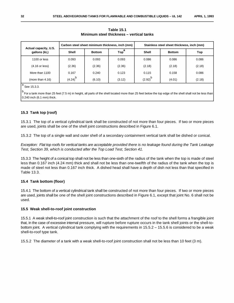
Table 15.1Minimum steel thickness – vertical tanks
Actual capacity, U.S.gallons (kL) Shell Bottom Top Shell Bottom Top
Carbon steel sheet minimum thickness, inch (mm) Stainless steel sheet thickness, inch (mm)
a
1100 or less 0.093 0.093 0.093 0.086 0.086 0.086
(4.16 or less) (2.36) (2.36) (2.36) (2.18) (2.18) (2.18)
More than 1100 0.167 0.240 0.123 0.115 0.158 0.086
(more than 4.16) (4.24) (6.10) (3.12) (2.92) (4.01) (2.18)b b
See 15.3.3.a
For a tank more than 25 feet (7.5 m) in height, all parts of the shell located more than 25 feet below the top edge of the shell shall not be less thanb
0.240 inch (6.1 mm) thick.
15.3 Tank top (roof)
15.3.1 The top of a vertical cylindrical tank shall be constructed of not more than four pieces. If two or more piecesare used, joints shall be one of the shell joint constructions described in Figure 6.1.
15.3.2 The top of a single wall and outer shell of a secondary containment vertical tank shall be dished or conical.
Exception: Flat top roofs for vertical tanks are acceptable provided there is no leakage found during the Tank LeakageTest, Section 39, which is conducted after the Top Load Test, Section 41.
15.3.3 The height of a conical top shall not be less than one-sixth of the radius of the tank when the top is made of steelless than 0.167 inch (4.24 mm) thick and shall not be less than one-twelfth of the radius of the tank when the top ismade of steel not less than 0.167 inch thick. A dished head shall have a depth of dish not less than that specified inTable 13.3.
15.4 Tank bottom (floor)
15.4.1 The bottom of a vertical cylindrical tank shall be constructed of not more than four pieces. If two or more piecesare used, joints shall be one of the shell joint constructions described in Figure 6.1, except that joint No. 6 shall not beused.
15.5 Weak shell-to-roof joint construction
15.5.1 A weak shell-to-roof joint construction is such that the attachment of the roof to the shell forms a frangible jointthat, in the case of excessive internal pressure, will rupture before rupture occurs in the tank shell joints or the shell-to-bottom joint. A vertical cylindrical tank complying with the requirements in 15.5.2 – 15.5.6 is considered to be a weakshell-to-roof type tank.
15.5.2 The diameter of a tank with a weak shell-to-roof joint construction shall not be less than 10 feet (3 m).

APRIL 1, 1993 STEEL ABOVEGROUND TANKS FOR FLAMMABLE AND COMBUSTIBLE LIQUIDS – UL 142 33
15.5.3 Except as required by 15.2.1 for a vertical cylindrical tank more than 25 feet (7.6 m) high, the shell of a tankconstructed with a weak shell-to-roof joint shall be made of steel not more than 0.179 inch (4.55 mm) thick for adistance of at least 5 feet (1.5 m) from the top.
15.5.4 The top of a vertical cylindrical tank constructed with a weak shell-to-roof joint shall be conical, having a slopenot greater than 2 inches (50.8 mm) in 12 inches (305 mm), nor less than 1-1/2 inches (3.8 mm) in 12 inches. The topshall be made of steel not more than 0.179 inch (4.55 mm) thick.
15.5.5 The roof of a vertical cylindrical tank constructed with a weak shell-to-roof joint shall be attached to the top anglewith a continuous single fillet weld on the top side only. The size of the weld shall not be larger than 3/16 inch (4.8 mm).The top angle shall not be smaller than 2-1/2 by 2-1/2 by 1/4 inch (64 by 64 by 6.4 mm) and shall be attached to theshell with a double-welded butt joint. See Details 5 and 6 of Figure 6.4. A roof-plate joint shall be as illustrated in Detail7 of Figure 6.4. Details 5, 6, and 7 of Figure 6.4 are the only joints that apply to a tank constructed with a weak shell-to-roof joint.
15.5.6 A vertical cylindrical tank constructed with a weak shell-to-roof joint or provided with a manhole in accordancewith the requirements in 8.6 shall have a vent opening for normal venting. The vent opening shall be in addition to thefill and withdrawal openings. The vent opening shall not be smaller than specified in Table 8.2.
RECTANGULAR CONSTRUCTIONS
16 GeneralSection 16 effective April 1, 1994
16.1 In addition to complying with the applicable requirements in Sections 4 – 12 for all tank constructions, primarycontainment rectangular tanks shall also comply with the requirements in Construction, Section 17, and Performance,Section 18.
17 ConstructionSection 17 effective April 1, 1994
17.1 General
17.1.1 Stiffening bars may be attached to the tank wall either by intermittent or continuous welding and may be placedon the inside or outside of the tank walls.
17.1.2 Tie rods may be used inside of the tank.
17.1.3 Baffles may be tack welded or continuously welded on the inside of the tank.
17.2 Steel thickness
17.2.1 Tanks of this type shall be constructed from steel not thinner than 0.093 inch (2.36 mm) if of carbon steel or0.071 inch (1.80 mm) if of stainless steel.

34 STEEL ABOVEGROUND TANKS FOR FLAMMABLE AND COMBUSTIBLE LIQUIDS – UL 142 APRIL 1, 1993
18 PerformanceSection 18 effective April 1, 1994
18.1 Hydrostatic strength test
18.1.1 The tank shall be tested to demonstrate that the strength of the assembly and the welded joints are inaccordance with these requirements.
18.1.2 The tank shall not rupture or leak when subjected to the Hydrostatic Strength Test, Section 40.
18.2 Top load test
18.2.1 After being subjected to the Top Load Test, Section 41, the tank shall then be subjected to the Leakage Test,Section 39, and shall not leak.
PART II – SECONDARY CONTAINMENT TANKS
ALL SECONDARY CONTAINMENT TANK CONSTRUCTIONS
19 GeneralSection 19 effective April 1, 1994
19.1 All secondary containment tanks shall be constructed to provide a means for monitoring leakage into the interstitial(annular) space through either the interior or exterior walls, and so that liquid can flow freely within the interstitial spaceto the point of monitoring.
HORIZONTAL CYLINDRICAL CONSTRUCTIONS
20 GeneralSection 20 effective April 1, 1994
20.1 In addition to complying with the applicable requirements in Sections 4 – 11 for all tank constructions, secondarycontainment horizontal cylindrical tanks shall also comply with the requirements in Construction, Section 21.
21 ConstructionSection 21 effective April 1, 1994
21.1 The primary containment tank shell of a secondary containment tank shall be constructed in accordance with PartI – Primary Containment Tanks, Horizontal Cylindrical Constructions, Sections 12 and 13.
21.2 The outer shell and head of a secondary containment tank shall meet the requirements specified for Part I –Primary Containment Tanks, Horizontal Cylindrical Constructions, Sections 12 and 13.
21.3 A secondary tank shell that is not in direct contact with the primary tank shall have standoffs positioned as shownin Figure 21.1.

APRIL 1, 1993 STEEL ABOVEGROUND TANKS FOR FLAMMABLE AND COMBUSTIBLE LIQUIDS – UL 142 35
Figure 21.1Secondary containment tank standoff positioning
21.4 The standoffs shown in Figure 21.1 may be oriented with the web either parallel or perpendicular to the shell andshall be a minimum of 3 by 1-1/2 inch (76.2 by 38.1 mm) channel [1/4 inch (6.4 mm) flange by 3/16 inch (4.8 mm) web]weighing 4.1 pounds per foot (6.1 kg per m).
21.5 If the outer shell of the secondary containment tank is in direct contact with the primary containment tank shell,the secondary containment shell may be constructed of steel with a thickness as specified in Table 21.1.
21.6 If the heads of the secondary containment tank are not in direct contact with the heads of the primary tank, theheads of the secondary tank shall have a minimum thickness as stated in Table 13.1 and be braced in accordance withFigures 13.1 and 13.2.
36 STEEL ABOVEGROUND TANKS FOR FLAMMABLE AND COMBUSTIBLE LIQUIDS – UL 142 APRIL 1, 1993
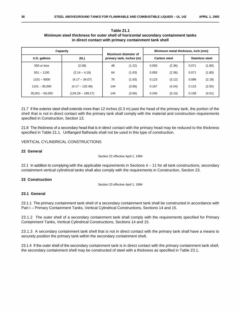
Table 21.1Minimum steel thickness for outer shell of horizontal secondary containment tanks
in direct contact with primary containment tank shell
Capacity Minimum metal thickness, inch (mm)Maximum diameter of
primary tank, inches (m)U.S. gallons (kL) Carbon steel Stainless steel
550 or less (2.08) 48 (1.22) 0.093 (2.36) 0.071 (1.80)
551 – 1100 (2.14 – 4.16) 64 (1.63) 0.093 (2.36) 0.071 (1.80)
1101 – 9000 (4.17 – 34.07) 76 (1.93) 0.123 (3.12) 0.086 (2.18)
1101 – 35,000 (4.17 – 132.49) 144 (3.66) 0.167 (4.24) 0.115 (2.92)
35,001 – 50,000 (134.29 – 189.27) 144 (3.66) 0.240 (6.10) 0.158 (4.01)
21.7 If the exterior steel shell extends more than 12 inches (0.3 m) past the head of the primary tank, the portion of theshell that is not in direct contact with the primary tank shall comply with the material and construction requirementsspecified in Construction, Section 13.
21.8 The thickness of a secondary head that is in direct contact with the primary head may be reduced to the thicknessspecified in Table 21.1. Unflanged flatheads shall not be used in this type of construction.
VERTICAL CYLINDRICAL CONSTRUCTIONS
22 GeneralSection 22 effective April 1, 1994
22.1 In addition to complying with the applicable requirements in Sections 4 – 11 for all tank constructions, secondarycontainment vertical cylindrical tanks shall also comply with the requirements in Construction, Section 23.
23 ConstructionSection 23 effective April 1, 1994
23.1 General
23.1.1 The primary containment tank shell of a secondary containment tank shall be constructed in accordance withPart I – Primary Containment Tanks, Vertical Cylindrical Constructions, Sections 14 and 15.
23.1.2 The outer shell of a secondary containment tank shall comply with the requirements specified for PrimaryContainment Tanks, Vertical Cylindrical Constructions, Sections 14 and 15.
23.1.3 A secondary containment tank shell that is not in direct contact with the primary tank shall have a means tosecurely position the primary tank within the secondary containment shell.
23.1.4 If the outer shell of the secondary containment tank is in direct contact with the primary containment tank shell,the secondary containment shell may be constructed of steel with a thickness as specified in Table 23.1.

APRIL 1, 1993 STEEL ABOVEGROUND TANKS FOR FLAMMABLE AND COMBUSTIBLE LIQUIDS – UL 142 37
Table 23.1Minimum steel thickness for outer shell of vertical secondary containment tanks
in direct contact with primary containment tank shell
Capacity, U.S. gallons Shell Bottoma
Carbon steel sheet minimum thickness, inch (mm)
1100 or less 0.093 (2.36) 0.093 (2.36)
Over 1100 0.123 (3.12) 0.240 (6.10)b
For SI units, 1 U.S. Gallon = 3.78 L.a
For a tank more than 25 feet (7.5 m) high, all parts of the shell located more than 25 feet below the top edge of the shell are not to be less than 0.167b
inch (4.24 mm) thick.
23.2 Tank bottom (floor)
23.2.1 The floor of the secondary containment shall be separate from and in addition to that of the primary containmentshell.
23.3 Weak shell-to-roof joint construction
23.3.1 Weak shell-to-roof joint construction is not to be used as emergency venting for vertical secondary containmenttanks.
RECTANGULAR CONSTRUCTIONS
24 GeneralSection 24 effective April 1, 1994
24.1 In addition to complying with the applicable requirements in Sections 4 – 11 for all tank constructions, secondarycontainment rectangular tanks shall also comply with the requirements in Construction, Section 25, and PerformanceTests, Section 26.
25 ConstructionSection 25 effective April 1, 1994
25.1 The primary containment tank shell of a secondary containment tank shall be constructed in accordance with PartI – Primary Containment Tanks, Rectangular Constructions, Sections 16 and 17.
25.2 The outer shell of a secondary containment tank shall comply with the requirements specified for Part I – PrimaryContainment Tanks, Rectangular Constructions, Sections 16 and 17.
25.3 The floor of the secondary containment shell shall be separate from and in addition to that of the primarycontainment shell.

38 STEEL ABOVEGROUND TANKS FOR FLAMMABLE AND COMBUSTIBLE LIQUIDS – UL 142 APRIL 1, 1993
26 Performance TestSection 26 effective April 1, 1994
26.1 Hydrostatic strength test
26.1.1 The secondary containment tank shall be tested to demonstrate that the strength of the assembly and weldedjoints are in accordance with these requirements.
26.1.2 Neither the primary or secondary containment tanks shall rupture or leak when subjected to the HydrostaticStrength Test, Section 40.
26.2 Top load test
26.2.1 After being subjected to the Top Load Test, Section 41, the tank shall then be subjected to the Leakage Test,Section 39, and shall not leak.
PART III – DIKED TANKS
27 GeneralSection 27 effective April 1, 1994
27.1 Details
27.1.1 The requirements in this Section cover open and closed top dike tank constructions.
27.1.2 In addition to complying with the applicable requirements in Sections 4 – 11 for all tank constructions and PartI (primary containment tanks) or II (secondary containment tanks) of this standard, a diked tank shall also comply withthe requirements in 27.2.1; Construction, Section 28; and Performance Tests, Section 29.
27.2 Dike capacity
27.2.1 The actual dike capacity less the volume displaced by the supports or other internal apparatus except the tankshall be at minimum, 110 percent of the actual capacity of the tank.
28 ConstructionSection 28 effective April 1, 1994
28.1 All diked tanks
28.1.1 The dike walls and floor shall be constructed of steel not thinner than 0.093 inch (2.36 mm) if of carbon steelor 0.071 inch (1.80 mm) if of stainless steel.
28.1.2 Stiffeners shall be provided on the top of all side walls.
28.1.3 Buttresses used to stiffen the side walls shall be at least the thickness of the side wall.
28.1.4 Horizontal cylindrical tanks shall be provided with supports that comply with the requirements of Part IV of thisstandard. If supports are provided for other tank constructions, they shall comply with the requirements of Part IV ofthis standard.

APRIL 1, 1993 STEEL ABOVEGROUND TANKS FOR FLAMMABLE AND COMBUSTIBLE LIQUIDS – UL 142 39
28.1.5 The supports shall be constructed so that liquid can flow freely at the lowest level in the dike area and shall notbecome easily blocked by debris.
28.1.6 The supports, tank, or both shall be mechanically secured to, or integral with, the dike to prevent rotation anduplift of the tank.
28.2 Open top dike constructions
28.2.1 Access and egress devices (ladder or stairs) shall be provided for the diked area if the height of the interior dikewall exceeds 6 feet (1.8 m).
28.3 Closed top dike constructions
28.3.1 Closed top dike tanks shall be provided with steel covers over the dike area to keep precipitation, debris, or otherelements from entering the diked area, while also allowing for inspection.
28.3.2 The dike shall be designed such that it cannot be pressurized, should fittings be capped.
28.3.3 Closed top dike constructions shall be provided with a means for emergency venting in accordance with Venting,Section 8.
28.3.4 Closed top dike constructions with covers intended to lift for emergency venting shall not be provided with ameans for securement or provision for locking and shall be marked in accordance with 48.4.1. Vent openings shall beconstructed to direct venting upward.
28.3.5 Covers shall be constructed so as to reduce the risk of injury to persons during intended use.
29 Performance TestsSection 29 effective April 1, 1994
29.1 General
29.1.1 Open and closed top dike tanks shall be subjected to the following tests.
29.2 Buoyancy test
29.2.1 When subjected to the Buoyancy Test, Section 42, there shall be no evidence of structural damage, and thetank shall show no evidence of uplifting from the dike floor.
29.3 Hydrostatic load test
29.3.1 When subjected to the Hydrostatic Load Test, Section 43, there shall be no structural damage or deflection ofthe dike walls exceeding L/250, where L is the length of the side wall. In addition, there shall be no leakage asevidenced by visual inspection of the dike.

40 STEEL ABOVEGROUND TANKS FOR FLAMMABLE AND COMBUSTIBLE LIQUIDS – UL 142 APRIL 1, 1993
PART IV – TANK SUPPORTS
30 GeneralSection 30 effective April 1, 1994
30.1 All constructions
30.1.1 These requirements cover supports integral to or secured to a tank or dike.
30.1.2 Tanks on supports shall be designed to withstand, at minimum, a static load of two times the weight of the fulltank.
30.1.3 Supports provided with thruholes for tiedown shall be slotted or open-ended to allow for thermal expansion andcontraction.
30.2 Horizontal cylindrical tank constructions
30.2.1 Saddles may be constructed as described in Construction, Section 31. Other saddle constructions or meansof support are to be evaluated by conducting structural analysis using calculations , tested in accordance witha
Performance Tests, Section 32, or other equivalent test method.
L.P. Zick's paper entitled "Stresses in Large Horizontal Pressure Vessels on Two Saddle Supports" and manya
published sources based on his paper are useful references for this purpose.
30.3 Vertical cylindrical tank constructions
30.3.1 Vertical cylindrical tanks on supports such as skirts or legs are to be evaluated by structural analysis usingcalculations or tested in accordance with Performance Tests, Section 32.b
"The Pressure Vessel Design Handbook" by Henry H. Bednar is a useful reference for this purpose.b
30.4 Rectangular tank constructions
30.4.1 Rectangular tanks on supports are to be evaluated by structural analysis using calculations or tested inaccordance with Performance Tests, Section 32.
31 ConstructionSection 31 effective April 1, 1994
31.1 General
31.1.1 Supports shall be constructed of material as described in Materials, Section 5.
31.2 Saddles
31.2.1 The minimum material thickness of saddles constructed in accordance with Figure 31.1 shall be as specifiedin Table 31.1.
31.2.2 Maximum height of saddles shall be 12 inches (305 mm) unless protected by materials having a fire resistancerating of not less than two hours.

JULY 22, 1998 STEEL ABOVEGROUND TANKS FOR FLAMMABLE AND COMBUSTIBLE LIQUIDS – UL 142 41
31.2.3 The base plate length shall be at least 90 percent of the tank diameter.
31.2.4 The stiffener thickness shall be a minimum of 3/8 inch (9.5 mm) for tank diameters 6 feet (1.8 m) or less anda minimum of 1/2 inch (12.7 mm) for tank diameters greater than 6 feet.
31.2.5 The saddles shall be positioned a distance of D/4 from the end of the primary tank, where D is the diameter ofthe tank.
Figure 31.1Saddles for horizontal cylindrical tanks
*Figure 31.1 revised July 22, 1998*

42 STEEL ABOVEGROUND TANKS FOR FLAMMABLE AND COMBUSTIBLE LIQUIDS – UL 142 JULY 22, 1998
Table 31.1Minimum material thicknesses for saddle constructions in inches
Part 550 or less 551 – 1100 1101 – 9000 1101 – 35,000 35,001 – 50,000
Maximum Tank Diameter 48 64 76 144 144
Top Flange Thickness 0.093 0.123 0.24 0.560 0.60
Wear Plate Thickness 0.093 0.123 0.24 0.240 0.365
Saddle Width 4.5 6.0 6.0 9.0 10
Base Plate Thickness 0.123 0.167 0.50 0.75 0.9
Base Plate Width 6.5 7.5 7.5 10 11
Web Thickness 0.093 0.123 0.167 0.240 0.365
Minimum Number of Stiffeners 3 3 4 7 6
31.2.6 Wear plates shall be used for tanks with capacities greater than 550 gallons (2.09 kL), and shall extend aminimum of 0.1 times the radius, in inches, above the saddle tips and have a minimum width of b + 10t inches, whereb is the width of the saddle and t is the thickness of the shell.
32 Performance TestsSection 32 effective April 1, 1994
32.1 As an option to structural analysis of the support, the tank may be subjected to the Tank Support Load Test,Section 44. There shall be no damage to or permanent deformation of the tank or supports.
PART V – TANK ACCESSORIES, COMPONENTS, AND SPECIAL CONSTRUCTIONS
33 GeneralSection 33 effective April 1, 1994
33.1 All types
33.1.1 The requirements in this section cover optional tank accessories, components, and special constructions.
33.2 Materials
33.2.1 All materials used in fabrication of the accessory shall be compatible with the base tank, flammable andcombustible liquid, and the physical and atmospheric conditions where the device may be used.
33.2.2 Polymerics and elastomers shall be evaluated for compatibility with fluids, surfaces, or atmospheric conditionswith which the part comes in contact. These materials shall comply with the requirements for gaskets and seals, UL157.

JULY 22, 1998 STEEL ABOVEGROUND TANKS FOR FLAMMABLE AND COMBUSTIBLE LIQUIDS – UL 142 42A
33.2.3 All accessories shall be constructed to minimize the stresses on the base tank.
34 LaddersSection 34 effective April 1, 1994
34.1 Exterior ladders shall comply with the construction requirements in accordance with the current edition ofOccupational Safety and Health Standards, Title 29 of the Code of Federal Regulations, Part 1910, Subpart D, Section1910.27 – Fixed Ladders.
34.2 Interior ladders shall comply with the exterior ladder requirements except that the climbing surface must be verticaland directly in line with the edge of the tank manhole. Manholes shall not be less than 24 inches (0.6 m) in diameter.Hatch covers, if used, shall not be of the self-locking type if they can be opened only from the outside of the tank.
34.3 Ladders shall be designed to withstand, at minimum, a static load of 1000 pounds (454 kg) for ladders with a climbof 10 feet (3 m) or less and 2000 pounds (909 kg) for ladders with a climb of greater than 10 feet. Suitability shall bedetermined by test as described in 34.4 and 34.5 or by calculations.
34.4 All ladders shall withstand the load described in 34.5 without damage to or permanent deformation of the ladderor tank.
34.5 Static Load (Ladders) – Ladders with a length of climb of 10 feet (3 m) or less shall support a static load of 1000pounds (454 kg). The load is to be applied for 1 minute to a 3-1/2 inch (89 mm) wide block resting on the center of thelongest rung. Ladders with a length of climb of greater than 10 feet shall support a static load of 2000 pounds (909 kg).The load is to be applied for 1 minute to the center of two rungs spaced 10 feet apart using 3-1/2 inch wide blocks.

42B STEEL ABOVEGROUND TANKS FOR FLAMMABLE AND COMBUSTIBLE LIQUIDS – UL 142 JULY 22, 1998
No Text on This Page

APRIL 1, 1993 STEEL ABOVEGROUND TANKS FOR FLAMMABLE AND COMBUSTIBLE LIQUIDS – UL 142 43
35 StairsSection 35 effective April 1, 1994
35.1 Stairs shall comply with the construction and performance requirements in accordance with the current editionof Occupational Safety and Health Standards, Title 29 of the Code of Federal Regulations, Part 1910, Subpart D,Section 1910.24 – Fixed Industrial Stairs.
35.2 Guardrails shall comply with Sub-paragraph 1910-23(d)(1) of the current edition of Occupational Safety andHealth Standards, Title 29 of the Code of Federal Regulations.
35.3 Spiral stairs on vertical tanks shall additionally comply with Sub-paragraph 1910.23(d)(2) of the current editionof Occupational Safety and Health Standards, Title 29 of the Code of Federal Regulations.
35.4 All stairs and guardrails shall withstand the loads described in 35.5 and 35.6, respectively, without damage to orpermanent deformation of the ladder or tank.
35.5 Static Load (Stairs) – A static load of 1000 pounds (454 kg) is to be evenly distributed over a one square foot (0.09m ) area on the center of the longest step for a period of one minute.2
35.6 Static Load (Guardrail) – A static load of 200 pounds (91 kg) is to be applied in various directions at a point on topof the rail located midway between the supports for a period of one minute. The load is to be applied using a 3-1/2 by3-1/2 inch (89 by 89 mm) steel plate.
36 RunwaysSection 36 effective April 1, 1994
36.1 Runways (catwalks) shall comply with the construction requirements in accordance with the current edition ofOccupational Safety and Health Standards, Title 29 of the Code of Federal Regulations, Part 1910, Subpart D, Section1910.23 – Guarding Floor and Wall Openings and Holes, sub-paragraph (c) – Protection of open-sided floors,platforms, and runways. Runways used below the top level of the tank are only required to have a guardrail on one side.
36.2 All runways and guardrails shall withstand the loads described in 36.3 and 35.6, respectively, without damage toor permanent deformation of the base ladder or tank.
36.3 Static Load (Runways) – A static load of 1000 pounds (454 kg) is to be evenly distributed over a one square foot(0.09 m ) area on the center of the longest step for a period of one minute.2
37 Heating Coils and Hot WellsSection 37 effective April 1, 1994
37.1 A heating coil or hot well that is provided as part of a tank assembly and handles a fluid other than that stored inthe tank, such as steam or hot water, shall have no joints in that portion located within the tank unless such joints arecontinuously welded or brazed. The coil or hot well connection shall exit from the tank above the liquid level, unlessmade of steel having a wall thickness not less than specified for that portion of the tank shell through which theconnection exists. A continuous full fillet weld shall be made where a connection pierces the tank or a manhole cover.

44 STEEL ABOVEGROUND TANKS FOR FLAMMABLE AND COMBUSTIBLE LIQUIDS – UL 142 APRIL 1, 1993
38 SumpsSection 38 effective April 1, 1994
38.1 A sump that is provided as part of a tank assembly shall be of steel having a thickness not less than that of thetank shell or bottom. It shall be attached to the tank using a continuous full fillet weld, inside and outside, or theequivalent.
PERFORMANCE TEST METHODS
39 Tank Leakage TestSection 39 effective April 1, 1994
39.1 Caution
39.1.1 Caution – Testing with air pressure presents a risk of injury to persons and personnel should be instructed inprecautions to be taken during such testing. The precautions should include the use of a pressure-relief device that willreduce the risk of the tank becoming pressurized in excess of the specified test pressure.
39.2 Primary containment tanks
39.2.1 The leakage test is to be conducted before painting the tank by either of the methods described in items (a) and(b). There shall be no evidence of leakage or sign of permanent deformation following the leakage test. A tank wall,head, or roof may deflect when subjected to the leakage test pressure, but shall return to its original position and shapewhen the test pressure is released.
a) Applying internal air pressure and using soap-suds, or equivalent material for the detection of leaks. Fora horizontal or rectangular tank, the test pressure is to be not less than 3 psig (21 kPa) or more than 5 psig (35kPa). For a vertical tank, the test pressure is not to be less than 1-1/2 psig (10 kPa) nor more than 2-1/2 psig(17 kPa) or that pressure above 1-1/2 psig which first causes visible deformation of the tank; or
b) Completely filling the tank with water, applying a 5 psig (35 kPa) hydrostatic pressure, and examining thetank for leakage. The tank is to be tested in the position in which it will be installed.
39.2.2 Each compartment of a tank having two or more compartments is to be tested separately for leakage.
39.3 Secondary containment tanks
39.3.1 After completion of the primary containment shell, the tank is to be checked for leakage using the methoddescribed in 39.2.1 and 39.2.2 for primary containment tanks.
39.3.2 Upon completion of the finished secondary containment tank, the primary tank is again to be pressurized usingthe method described in 39.2.1 and 39.2.2 and held for 1 hour to check for leakage. A continuous drop in pressure willbe considered evidence of leakage.

APRIL 1, 1993 STEEL ABOVEGROUND TANKS FOR FLAMMABLE AND COMBUSTIBLE LIQUIDS – UL 142 45
39.3.3 While maintaining pressure on the primary tank, the interstitial (annular) space bounded by the primary andsecondary tank is to be pressurized to the pressures indicated in 39.2.1 and checked for external leakage by applyinga leak detection solution. There shall be no evidence of leakage or sign of permanent deformation following theleakage test. A tank wall, head, or roof may deflect when subjected to the leakage test pressure, but shall return to itsoriginal position and shape when the test pressure is released.
39.3.4 As an option to the leakage test described in 39.3.2 and 39.3.3, the annular space may be tested by applyinga vacuum of at least 13 inches of mercury for a minimum of 12 hours. If the tank is unable to maintain the vacuum (plusor minus 2 inches of mercury) for the specified time, the tank shall be retested using the method described in 39.3.2and 39.3.3.
40 Hydrostatic Strength TestSection 40 effective April 1, 1994
40.1 General
40.1.1 The hydrostatic strength test is to be conducted as described in 40.3.1 and 40.4.1 using the test apparatusdescribed in 40.2.1. Neither the primary containment tank nor the secondary containment shell shall rupture or leakwhen subjected to this test.
40.2 Test apparatus
40.2.1 The source of water pressure is to be capable of maintaining a pressure of at least 30 psig (207 kPa) for a periodof not less than 2 minutes. The pressure gauges are to be calibrated and have a dial range of 0 – 50 or 0 – 60 psig (345or 415 kPa), a face size of at least 3-1/2 inches (89 mm) in diameter, graduations of 1 psig or 10 kPa maximum, andan accuracy of ±1 percent of the full scale reading. Piping and fittings as shown in Figure 40.1 are to be appropriatefor the test pressure.
40.3 Primary containment tanks
40.3.1 The tank and connections are to be arranged as shown in Figure 40.1. All unused openings in the tank to betested are to be plugged.
a) The tank is to be completely filled with water, and all air expelled from the tank.
b) Pressure is to be applied gradually to the tank in increments of 5 psig (35 kPa) at a rate not exceeding 2 psig(14 kPa) per minute. The pressure is to be held for 2 minutes after each increment of 5 psig until the testpressure of 25 psig (172 kPa) is attained.
Exception: Test pressure of 15 psig (103 kPa) may be used instead of 25 psig if tanks are marked as specifiedin 48.5.1.
c) Once the test pressure is attained, the tank is to be examined for visible signs of leakage or rupture.
40.4 Secondary containment tanks
40.4.1 Upon completion of the test on the primary containment shell as described in 40.3.1, pressure is to be reducedin the primary containment shell, the interstitial (annular) space is to be filled with water, and the test method is to berepeated to test the secondary containment shell. Pressure in the primary tank is to be maintained while testing theannular space.
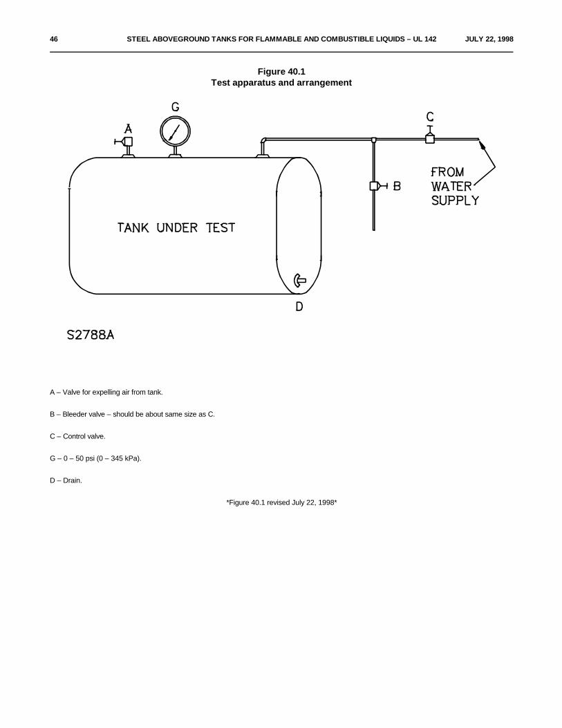
46 STEEL ABOVEGROUND TANKS FOR FLAMMABLE AND COMBUSTIBLE LIQUIDS – UL 142 JULY 22, 1998
Figure 40.1Test apparatus and arrangement
A – Valve for expelling air from tank.
B – Bleeder valve – should be about same size as C.
C – Control valve.
G – 0 – 50 psi (0 – 345 kPa).
D – Drain.
*Figure 40.1 revised July 22, 1998*

JULY 22, 1998 STEEL ABOVEGROUND TANKS FOR FLAMMABLE AND COMBUSTIBLE LIQUIDS – UL 142 46A
41 Top Load TestSection 41 effective April 1, 1994
41.1 The top surface of flat top tanks is to be subjected to a 1000 pound (454 kg) load, applied over a one square foot(0.09 m ) area at the weakest part of the tank top for a period of 5 minutes.2
41.2 The load is then to be removed, and the tank subjected to the Tank Leakage Test, Section 39.
42 Buoyancy TestSection 42 effective April 1, 1994
42.1 The diked area is to be filled with water to its maximum capacity while the tank remains empty. This condition isto be maintained for a minimum of one hour. The tank shall not show uplifting from the dike floor.

46B STEEL ABOVEGROUND TANKS FOR FLAMMABLE AND COMBUSTIBLE LIQUIDS – UL 142 JULY 22, 1998
No Text on This Page

APRIL 1, 1993 STEEL ABOVEGROUND TANKS FOR FLAMMABLE AND COMBUSTIBLE LIQUIDS – UL 142 47
42.2 The dike is then to be emptied and the tank and dike examined. There shall be no evidence of structural damage.
43 Hydrostatic Load TestSection 43 effective April 1, 1994
43.1 This test is to be conducted immediately following the buoyancy test. With the dike filled with water, there shallbe no structural damage or deflection of the dike walls exceeding L/250, where L is the length of the side wall. Inaddition, there shall be no leakage as evidenced by visual inspection of the dike.
43.2 With the diked area empty, the tank is to be filled with water to its maximum capacity. This condition is to bemaintained for a minimum of one hour.
44 Tank Support Load TestSection 44 effective April 1, 1994
44.1 A tank provided with integral supports shall show no evidence of permanent deformation or damage to the tankor supports when tested as described in 44.2.
44.2 The tank is to be completely filled with water. An evenly distributed load equal to the weight of the filled tank isto be placed across the top of the filled tank on a line parallel to the longitudinal axis of the tank. The tank and supportsshall withstand this load for 2 minutes.
MANUFACTURING AND PRODUCTION TESTS
45 Primary and Secondary Containment TanksSection 45 effective April 1, 1994
45.1 Each primary and secondary containment tank, before painting, shall be tested by the manufacturer anddetermined to be tight against leakage using the method of the Tank Leakage Test, Section 39.
45.2 If leaks are noted during testing, the tank is to be made tight by welding and retested. Defects in welds are to berepaired by chipping or melting out from one or both sides of the joint, as required, and rewelding.
46 Diked TanksSection 46 effective April 1, 1994
46.1 Each primary or secondary containment tank, before painting, shall be tested by the manufacturer and determinedto be tight against leakage using the method of the Tank Leakage Test, Section 39.
46.2 Each dike shell is to be inspected before painting for welding defects with a dye penetrant, magnet-flux, or otheracceptable non-destructive testing method. If all seams are double welded (inside and outside), visual inspection maybe used. The Hydrostatic Load Test, Section 43, may also be used to determine welding defects.

48 STEEL ABOVEGROUND TANKS FOR FLAMMABLE AND COMBUSTIBLE LIQUIDS – UL 142 APRIL 1, 1993
46.3 If leaks are noted during testing, the tank is to be made tight by welding and retested. Defects in welds are to berepaired by chipping or melting out from one or both sides of the joint, as required, and rewelding.
MARKINGS
47 GeneralSection 47 effective April 1, 1994
47.1 Each tank shall be marked as indicated in Marking Elements, Section 48, using the method described in MarkingMethod and Location, Section 49.
48 Marking ElementsSection 48 effective April 1, 1994
48.1 All tanks
48.1.1 Each tank shall be marked with:
a) The manufacturer's name, trade name, or trademark or other descriptive marking by which the organizationresponsible for the product can be identified.
b) One of the following statements, as applicable:
1) "This Tank Requires Emergency Relief Venting. Capacity Not Less Than ____ Cubic Feet PerHour," with the appropriate value derived from Table 8.1 inserted; or
2) For vertical cylindrical tanks of the weak shell-to-roof joint design: "Built To Weak Shell-To-RoofJoint Design"; or
3) For tanks provided with a manhole of the long bolt type in accordance with the requirements in 8.7,the manhole cover shall be marked: "This Manhole Is Provided With Long Bolts To Permit EmergencyRelief Venting. Do Not Replace With Shorter Bolts."
c) The statement: "This Tank is Intended for Stationary Installation Only."
d) If a manufacturer produces tanks at more than one factory, each tank shall have a distinctive marking bywhich it can be identified as the product of a particular factory.
e) Identification of the emergency vent openings.
48.2 Compartment tanks
48.2.1 In addition to the markings required in 48.1.1, compartment tanks shall also be marked with the following:
a) The applicable venting statements as described in 48.1.1(b) for each compartment.
b) Identification of the emergency vent openings for each compartment.

APRIL 1, 1993 STEEL ABOVEGROUND TANKS FOR FLAMMABLE AND COMBUSTIBLE LIQUIDS – UL 142 49
48.3 Secondary containment tanks
48.3.1 In addition to the markings required in 48.1.1 and 48.2.1, as applicable, secondary containment tanks shall alsobe marked with the following statements:
a) "The Annular Space Requires Emergency Relief Venting. Capacity Not Less Than ____ Cubic Feet PerHour," with the appropriate value derived from Table 8.1 inserted.
b) "Pressurize Primary Tank When Pressure Testing Annular Space" or equivalent wording.
48.4 Diked tanks
48.4.1 In addition to the markings required by 48.1.1 and 48.2.1, diked tanks shall also be marked with the statements:
a) The capacity of the diked area in U.S. gallons. The capacity may also be expressed in terms of percentcontainment of the primary tank.
b) (For closed top diked tanks only where the cover is used for emergency venting) "Cover Used ForEmergency Venting. Do Not Secure Cover."
48.5 Rectangular tanks
48.5.1 If a tank is subjected to the 15 psig (103 kPa) hydrostatic test pressure as covered in the Exception to 40.3.1(b),the tank shall be marked to indicate a maximum leakage test pressure of 3 psig (21 kPa).
49 Marking Method and LocationSection 49 effective April 1, 1994
49.1 The required marking shall be embossed, etched, stamped on a nameplate of corrosion resistant metal, or asdescribed in 49.2. The markings shall be in a size and style of type corresponding to 18 point Franklin Gothic [1/4 inch(6.4 mm) high letters] or the equivalent. The nameplate shall be attached by welding or brazing or by attaching it bydrive screws, rivets, welding, or brazing to a bracket or holder that is then welded or brazed to the tank.
49.2 If a pressure-sensitive label, ink or paint stenciling, or other method is used, it shall comply with the requirementsin the Standard for Marking and Labeling Systems, UL 969; be suitable for outdoor use and exposure to fuels andgasoline; and have a minimum surface temperature rating of 60EC (140EF).
49.3 For primary and secondary containment tanks, the nameplate shall be secured to the tank.
49.4 For tanks provided with a manhole of the long bolt type, the marking in 48.1.1 shall be secured directly to themanhole cover.
49.5 For diked tanks, the nameplate shall be secured to the exterior of the dike shell.

50 STEEL ABOVEGROUND TANKS FOR FLAMMABLE AND COMBUSTIBLE LIQUIDS – UL 142 APRIL 1, 1993
No Text on This Page

APRIL 1, 1993 STEEL ABOVEGROUND TANKS FOR FLAMMABLE AND COMBUSTIBLE LIQUIDS – UL 142 A1
APPENDIX A
Capacity and Wetted Area Tables
Table A1Gallon capacity per foot of length
Diameter in inches length Diameter in inches length Diameter in inches lengthU.S. gallons 1-foot U.S. gallons 1-foot U.S. gallons 1-foot
24 23.50 65 172.38 105 449.8225 25.50 66 177.72 106 458.3026 27.58 67 183.15 107 467.7027 29.74 68 188.66 108 475.8928 31.99 69 194.25 109 485.0029 34.31 70 199.92 110 493.7030 36.72 71 205.67 111 502.7031 39.21 72 211.51 112 511.9032 41.78 73 217.42 113 521.4033 44.43 74 223.42 114 530.2434 47.16 75 229.50 115 540.0035 49.98 76 235.66 116 549.5036 52.88 77 241.90 117 558.5137 55.86 78 248.23 118 568.0038 58.92 79 254.63 119 577.8039 62.06 80 261.12 120 587.5240 65.28 81 267.69 121 597.7041 68.58 82 274.34 122 607.2742 71.97 83 281.07 123 617.2643 75.44 84 287.88 124 627.0044 78.99 85 294.78 125 638.2045 82.62 86 301.76 126 647.7446 86.33 87 308.81 127 658.6047 90.13 88 315.95 128 668.4748 94.00 89 323.18 129 678.9549 97.96 90 330.48 130 690.3050 102.00 91 337.86 131 700.1751 106.12 92 345.33 132 710.9052 110.32 93 352.88 133 721.7153 114.61 94 360.51 134 732.6054 118.97 95 368.22 135 743.5855 123.42 96 376.01 136 754.6456 127.95 97 383.89 137 765.7857 132.56 98 391.84 138 776.9958 137.25 99 399.88 139 788.3059 142.02 100 408.00 140 799.6860 146.88 101 416.00 141 811.1461 151.82 102 424.48 142 822.6962 156.83 103 433.10 143 834.3263 161.93 104 441.80 144 846.0364 167.12

A2 STEEL ABOVEGROUND TANKS FOR FLAMMABLE AND COMBUSTIBLE LIQUIDS – UL 142 APRIL 1, 1993
Table A2Wetted areas for horizontal tanks
(Wetted area equals 75 percent of total area)
Tank diameter,feet 3 4 5 6 7 8 9 10 11 12
a
Tank length,feet Wetted area of tanks with flat heads, square feet
a b
3 32
4 39 55
5 46 65 88
6 53 74 100 128
7 60 84 112 142 173
8 67 93 124 156 190 226
9 74 102 136 170 206 245 286
10 81 112 147 184 223 264 308 353
11 88 121 159 198 239 283 329 377 428
12 95 131 171 213 256 301 650 400 454 509
13 102 140 183 227 272 320 371 424 480 537
14 109 150 194 241 289 339 393 447 506 565
15 116 159 206 255 305 358 414 471 532 594
16 123 169 218 269 322 377 435 495 558 622
17 130 178 230 283 338 395 456 518 584 650
18 137 188 242 298 355 414 477 542 610 678
19 197 253 312 371 433 499 656 636 707
20 206 265 326 388 452 520 589 662 735
21 216 277 340 404 471 541 612 688 763
22 225 289 354 421 490 562 636 714 792
23 235 300 368 437 508 584 659 740 820
24 244 312 383 454 527 605 683 765 848
25 324 397 470 546 626 706 791 876
26 336 411 487 565 647 730 817 905
(Continued)

JULY 22, 1998 STEEL ABOVEGROUND TANKS FOR FLAMMABLE AND COMBUSTIBLE LIQUIDS – UL 142 A3
Table A2 (Cont'd)
Tank diameter,feet 3 4 5 6 7 8 9 10 11 12
a
Tank length,feet Wetted area of tanks with flat heads, square feet
a b
27 347 425 503 584 668 754 843 933
28 359 440 520 603 690 777 869 961
29 371 454 536 321 711 801 895 989
30 383 468 553 340 732 824 921 1018
31 395 482 569 659 753 848 947 1046
32 496 586 678 775 871 972 1074
33 510 602 697 796 895 999 1103
34 524 619 715 817 918 1025 1131
35 539 635 734 838 942 1051 1159
36 553 652 753 860 966 1077 1187
37 567 668 772 881 989 1103 1216
38 685 791 902 1013 1129 1244
39 701 810 923 1036 1155 1272
40 718 828 944 1060 1181 1301
41 734 847 966 1083 1207 1329
42 751 866 987 1107 1233 1357
43 767 885 1008 1130 1259 1385
44 904 1029 1154 1284 1414
45 923 1051 1178 1310 1442
46 941 1072 1201 1336 1470
47 960 1093 1225 1362 1798
48 979 1114 1248 1388 1527
49 998 1135 1272 1414 1555
50 1157 1295 1440 1583
(Continued)

A4 STEEL ABOVEGROUND TANKS FOR FLAMMABLE AND COMBUSTIBLE LIQUIDS – UL 142 JULY 22, 1998
Table A2 (Cont'd)
Tank diameter,feet 3 4 5 6 7 8 9 10 11 12
a
Tank length,feet Wetted area of tanks with flat heads, square feet
a b
51 1178 1319 1466 1612
52 1199 1342 1492 1640
53 1220 1366 1518 1668
54 1246 1389 1544 1725
55 1263 1413 1570 1753
56 1437 1593 1781
57 1460 1622 1809
58 1484 1648 1839
59 1507 1674
60 1531 1700
61 1726
62 1752
63 1778
64 1803
65 1829
66 1855
For SI units, 1 ft = 0.3 m.a
For SI units, 1 ft = 0.09 m .b 2 2
*Table A2 revised July 22, 1998*

APRIL 1, 1993 STEEL ABOVEGROUND TANKS FOR FLAMMABLE AND COMBUSTIBLE LIQUIDS – UL 142 A5
Table A3Wetted areas for vertical tanks
(Area of shell to elevation not more than 30 feet above bottom)
Tank diameter,feet 3 4 5 6 7 8 9 10 11 12
a
Tank length,feet Wetted area of tanks with flat heads, square feet
a b
3 28
4 38 50
5 47 63 79
6 56 76 94 113
7 66 88 110 132 154
8 75 101 127 151 176 201
9 85 113 141 170 198 226 255
10 94 126 157 189 220 251 283 314
11 103 139 173 208 242 276 311 345 381
12 113 151 188 227 264 301 340 377 415 452
13 164 204 246 286 326 368 408 450 490
14 176 220 265 308 351 396 440 484 528
15 189 236 284 330 377 424 471 519 566
16 202 251 302 352 402 453 502 554 603
17 267 321 374 427 481 534 588 641
18 283 340 396 452 510 565 623 679
19 298 359 418 477 538 597 657 716
20 314 378 440 502 566 628 692 754
21 397 462 527 594 659 727 792
22 416 484 552 623 691 761 829
23 435 506 577 651 722 796 867
(Continued)

A6 STEEL ABOVEGROUND TANKS FOR FLAMMABLE AND COMBUSTIBLE LIQUIDS – UL 142 JULY 22, 1998
Table A3 (Cont'd)
Tank diameter,feet 3 4 5 6 7 8 9 10 11 12
a
Tank length,feet Wetted area of tanks with flat heads, square feet
a b
24 454 528 602 679 757 830 905
25 550 628 708 785 865 943
26 572 653 736 816 900 980
27 594 678 764 848 934 1018
28 616 703 792 879 969 1056
29 728 821 911 1003 1093
30 753 849 942 1038 1131
For SI units, 1 ft = 0.3 m.a
For SI units, 1 ft = 0.09 m .b 2 2
*Table A3 revised July 22, 1998*

JULY 22, 1998 STEEL ABOVEGROUND TANKS FOR FLAMMABLE AND COMBUSTIBLE LIQUIDS – CRG 142 CRG1
CRG 142
CANADIAN REQUIREMENTS COMPARISON GUIDE
UL AND CANADIANSTANDARDS FOR STEEL ABOVEGROUND TANKS FOR FLAMMABLE AND COMBUSTIBLE LIQUIDS

CRG2 STEEL ABOVEGROUND TANKS FOR FLAMMABLE AND COMBUSTIBLE LIQUIDS – CRG 142 JULY 22, 1998
Product Category: Steel Aboveground Tanks for Flammable and Combustible LiquidsUL Category Control Number: EEEV
UL Standard: Standard for Steel Aboveground Tanks for Flammable and Combustible LiquidsUL 142Seventh Edition
Canadian Standard: (1) Aboveground Steel Contained Tank Assemblies for Flammable and Combustible Liquids
ULC-S653-94First Edition
(2) Shop Fabricated Steel Aboveground Horizontal Tanks for Flammable and Combustible Liquids
ULC-S601-93Second Edition
(3) Shop Fabricated Steel Aboveground Vertical Tanks for Flammable and Combustible Liquids
ULC-S630-93 Second Edition
This Canadian Requirements Comparison Guide is only intended to identify Canadian requirements that must be appliedin addition to the requirements in the UL Standard to obtain a c-UL Mark. The guide is not intended to replace athorough review and comparison of the requirements applicable to the product category as contained in the applicableUL and Canadian Standards. Where requirements are not specifically addressed, compliance with the requirementsin the UL Standard satisfy the requirements in the Canadian Standard.
The actual requirements applied for a c-UL product investigation may differ from those identified in this guide based onthe specific features, characteristics, components, materials, or systems used in the product.
CRG: 142Issue No.: 1Issue Date: July 22, 1998
Revisions of this guide will be made by issuing revised or additional pages bearing their date of issue. A CanadianRequirements Comparison Guide is current only if it incorporates the most recently adopted revisions, all of which areitemized on the transmittal notice that accompanies the latest set of revision pages for the Guide.

JULY 22, 1998 STEEL ABOVEGROUND TANKS FOR FLAMMABLE AND COMBUSTIBLE LIQUIDS – CRG 142 CRG3
The following outlines the requirements contained in ULC-S653-94, ULC-S601-93, ULC-S630-93, that are in additionto the requirements in UL 142 that must be met in order for a product to bear the appropriate UL Marking. UL providesa certification program for products that meet the Canadian requirements. The c-UL Mark provides assurance that theproduct as evaluated by UL complies with the appropriate Canadian requirements.
Copyright © 1998 Underwriters Laboratories Inc.

CRG4 STEEL ABOVEGROUND TANKS FOR FLAMMABLE AND COMBUSTIBLE LIQUIDS – CRG 142 JULY 22, 1998
Requirements Topics ULC-S653-94 Clause Comparison
The diked tank shall be constructed per ULC-S653-94.
The primary tank shall be constructed per ULC-S601-93Horizontal, ULC-S630-93 Vertical
DIKED TANKS
Spill Containment Required per ULC/ORD-C142.19.
Overfill Protection Required per ULC/ORD-C58.15.
Containment Not less than 110%
Bottom Thickness If on ground or less than 100 mm above ground then tshall be not less than 6 mm.
If on supports and not less than 100 mm above groundsee Table 1 (per standard).
Drain Openings Not permitted.
Lift Lugs Mandatory (no deformation).
Access Required if the vertical distance between the fillconnection and the grade exceeds 1 m.
Stairs Per National Building Code of Canada and authorityhaving jurisdiction.
Welders Carry valid arc-welding operator identification certificateissued by authority having jurisdiction.
Welds Figure 1, 2, and 3 (per standard).
Weld Slag Must be removed from all welds.
Venting Secondary – Normal Vent and Emergency vent.
Marking 1) Name of manufacturer.
2) Year of manufacturer.
3) Label of certifying agency.
4) All marking for primary tank standard.
5) "This contained tank assembly includes anaboveground tank of ___ L capacity manufactured by ___in accordance with ** (**primary tank standard number)."
6) "Check weekly for accumulation of liquids incontainment and remove any accumulated precipitation."
7) "Consult the authority having jurisdiction prior toinstallation."
Installation Instructions Required.

JULY 22, 1998 STEEL ABOVEGROUND TANKS FOR FLAMMABLE AND COMBUSTIBLE LIQUIDS – CRG 142 CRG5
Requirements Topics ULC-S601-93 Clause Comparison
PRIMARY/SECONDARY CONTAINMENT HORIZONTAL TANK
Size Table 2 (max size 52,000 gal).
Material Thickness Table 2.
Length Max shell length 4D.
LIFT LUGS
Use Lift Lugs are required. 5,000 gallons or less may have1 lug. Manufactured per Figure 2. Installed per Figure3.
WELDING
Certification Operator Id certificate issued by authority havingjurisdiction.
Slag Must Be Removed.
Seal Welds (Par. 3.6.4) Required, Figure 4.
Shell Joints Figure 5.
LEADS
Number of Pieces Max 3.
Joints Figure 6.
Flange Length At least 0.393 inch (10 mm).
Unflanged Flat Heads Figure 7.
TANK CONNECTIONS
Type of Connections (Par. 3.9.2) Figure 8.
Thread Length (Par. 3.9.8) Figure 8.
Identification of Vent Fittings (Par. 3.9.8) Painted red.
VENTING
Normal (not compatible) Table 4.
Emergency (not compatible) Table 4.

CRG6 STEEL ABOVEGROUND TANKS FOR FLAMMABLE AND COMBUSTIBLE LIQUIDS – CRG 142 JULY 22, 1998
Requirements Topics ULC-S601-93 Clause Comparison
MANWAYS
Size At least 600 mm (24 inch).
Reverse flange Not allowed.
SADDLES
Use Can use UL's w/o test or can use their own. Needdrawing.
SPILL CONTAINMENT
Required (Par. 3.15.2) Yes ULC/ORD-C142.19.
MARKING
Required 1) Name of manufacturer.
2) Primary tank head and shell metal thickness, mm.
3) Secondary containment head and shell metalthickness, mm.
4) Diameter.
5) Primary tank capacity, L.
6) Maximum operating pressure, 7 kPa.
7) Maximum operating vacuum, 300 Pa.
8) Capacity of total primary tank venting (normal +Emergency), m /min.3
9) Year of manufacture.
10) Label of certifying agency.
Permanency Resistant to environment.
Marking next to vent "Interstice Emergency Venting – Do Not Remove."
Marking next to vacuum monitor "Secondary Containment Vacuum Monitor – Do Notdevice Open Valve or Remove. A Vacuum Gauge Reading
Below 42 kPa Indicates A Problem. Contact TheOriginal Tank Manufacturer."
Marking next to lift lug "Double Wall Tank Empty Weight ________ KG (____Tons)."
SHIPPING
Requirements All double wall tanks shall be shipped to the site with aminimum vacuum of 51 kPa gauge on the interstice.

JULY 22, 1998 STEEL ABOVEGROUND TANKS FOR FLAMMABLE AND COMBUSTIBLE LIQUIDS – CRG 142 CRG7
Requirements Topics ULC-S630-93 Clause Comparison
PRIMARY/SECONDARY CONTAINMENT VERTICAL TANK
Size Table 1 (max size 46,000 gal).
Material Thickness Table 1.
Maximum Height Max Shell Length 4D.
LIFT LUGS
Use Lift Lugs Required, Figure 2.
WELDING
Certification Operator Id certificate issued by authority havingjurisdiction.
Slag Must Be Removed.
Shell Joints Figure 3, min vertical offset of 100 m.
Bottom Joints Figure 4.
TANK TOP
Number of Pieces Max 4.
Joints Figure 5.
Roof Conical, flanged and dished, semi-elliptical, orhemispherical. Primary Tank may have a flat roof.
Shell to Roof Joint Not weak.
Cone Height D/10.
TANK CONNECTIONS
Type of Connections Figure 6.
Thread Length Figure 6.
Identification of Vent Fittings Painted red.
VENTING
Normal (not compatible) Table 3.
62 mm < 500 L.
88.9 mm > 5000 L.
Emergency (not compatible) Table 3.
MANWAYS
Size Minimum of 600 mm (24 inch).
Design Figure 8.
Reverse Flange Not allowed.

CRG8 STEEL ABOVEGROUND TANKS FOR FLAMMABLE AND COMBUSTIBLE LIQUIDS – CRG 142 JULY 22, 1998
Requirements Topics ULC-S630-93 Clause Comparison
SPILL CONTAINMENT
Required (Par. 3.15.2) Must comply with ULC/ORD-C142.19.
OVERFILL CONTAINMENT
Required Must comply with ULC/ORD-C58.15.
MARKING
Required 1) Name of manufacturer.
2) Primary tank head and shell metal thickness, mm.
3) Secondary containment head and shell metalthickness, mm.
4) Diameter.
5) Primary tank capacity, L.
6) Maximum operating pressure, 7 kPa.
7) Maximum operating vacuum, 300 Pa.
8) Capacity of total primary tank venting (normal +Emergency), m /min.3
9) Year of manufacture.
10) Label of certifying agency.
11) Sec Shell + Bottom Thickness mm.
Permanency Resistant to environment.
Marking Next to Vent "Interstice Emergency Venting – Do Not Remove."
Marking Next to Vacuum Monitor "Secondary Containment Vacuum Monitor – Do NotDevice Open Valve or Remove. A Vacuum Gauge Reading
Below 42 kPa Indicates A Problem. Contact TheOriginal Tank Manufacturer."
Marking Next to Lift Lug "Double Wall Tank Empty Weight ____ KG(___ Tons)."
SHIPPING
Requirements All Double wall tanks shall be shipped to the site with aminimum vacuum of 51 kPa gauge on the interstice.
SECONDARY CONTAINMENT
Shell Table 5.
Fittings Figure 10.

JULY 22, 1998 STEEL ABOVEGROUND TANKS FOR FLAMMABLE AND COMBUSTIBLE LIQUIDS – CRG 142 CRG9
Requirements Topics ULC-S630-93 Clause Comparison
Welds Figure 3, 4, 10, 12.
Venting Table 6 and Figure 1.
MONITORING
Required Yes – Vacuum.
ANCHORS
Required Optional
COATINGS
Requirements None

CRG10 STEEL ABOVEGROUND TANKS FOR FLAMMABLE AND COMBUSTIBLE LIQUIDS – CRG 142 JULY 22, 1998
No Text on This Page
Copyright © 2022 FDOKUMEN