State of Colorado GUIDELINES FOR PROJECT REVIEW
63
State of Colorado Department of Natural Resources Division of Water Resources Office of the State Engineer Dam Safety GUIDELINES FOR PROJECT REVIEW EFFECTIVE DATE: January 21, 2020 1313 Sherman Street, Room 818 Centennial Building Denver, Colorado 303-866-3581
-
Upload
khangminh22 -
Category
Documents
-
view
0 -
download
0
Transcript of State of Colorado GUIDELINES FOR PROJECT REVIEW

State of Colorado Department of Natural Resources
Division of Water Resources Office of the State Engineer
Dam Safety
GUIDELINES FOR PROJECT REVIEW
EFFECTIVE DATE: January 21, 2020
1313 Sherman Street, Room 818 Centennial Building Denver, Colorado
303-866-3581

This page left blank intentionally

i
TABLE OF CONTENTS
PURPOSE OF THE DAM SAFETY PROJECT REVIEW GUIDE ............................. 1 Review and Approval of a Project Design ................................................................................. 1 Project Review Guide Structure ............................................................................................ 2 Other Considerations ......................................................................................................... 3
PART I - ADMINISTRATIVE REQUIREMENTS ............................................... 4
I-A. Design Submittal ........................................................................................................ 4 1. Application Form ........................................................................................................ 4 2. Engineer’s Qualification Statement and Affidavit ................................................................. 4 3. Construction Plans ...................................................................................................... 4 4. Construction Specifications ............................................................................................ 4 5. Hazard Classification Report .......................................................................................... 5 6. Hydrology Report ........................................................................................................ 5 7. Geotechnical Report .................................................................................................... 5 8. Design Report ............................................................................................................ 5 9. Instrumentation and Monitoring Plan ................................................................................ 6 10. Detailed Cost Estimate ................................................................................................. 6 11. Filing Fee ................................................................................................................. 6
I-B. Supplemental Filing .................................................................................................... 6 1. Corrected documents according to DSB design review memo ................................................... 6 2. Revised cost estimate .................................................................................................. 6
I-C. Filing for Construction Approval .................................................................................... 6 1. Final project design reports ........................................................................................... 6 2. Final cover sheet drawing .............................................................................................. 6 3. Construction Plans (i.e., drawings) ................................................................................... 7 4. Specifications ............................................................................................................ 7 5. Design Criteria Memorandum.......................................................................................... 7
I-D. Construction Phase Filing ............................................................................................. 7 1. Construction Observation Plan ........................................................................................ 7 2. Construction Progress Reports ........................................................................................ 7 3. Design Change Orders .................................................................................................. 7
I-E. Project Completion Filing ............................................................................................ 7 1. Engineer’s Certification of Completion .............................................................................. 7 2. As-Constructed Drawings ............................................................................................... 8 3. Final Construction Report .............................................................................................. 8 4. Monitoring Plans ......................................................................................................... 8 5. Emergency Action Plan (High and Significant Hazard dams, only) .............................................. 8 6. Construction Cost Information ........................................................................................ 8
PART II - DESIGN AND TECHNICAL CRITERIA ............................................. 9
II-A. Hazard Classification Report ......................................................................................... 9

ii
1. General description of dam/reservoir and downstream inundation limits .................................... 9 2. Detailed description of breach hydrograph estimation process ................................................. 9 3. Description of baseline conditions assumed for breach analysis ................................................ 9 4. Detailed description of routing breach hydrograph downstream of dam ...................................... 9 5. Tabulation of dam break and channel discharge parameters ................................................... 9 6. Dam failure inundation maps showing hydraulics at critical locations ......................................... 9 7. Appropriate annotated cross-sections ............................................................................... 9 8. Modeling parameters ................................................................................................. 10 9. Conclusions and statement of recommended hazard classification .......................................... 10 10. Digital Submittal ....................................................................................................... 10
II-B. Hydrologic Hazard Evaluation ..................................................................................... 11 1. Overtopping Dam Breach Analysis (or other plausible hydrologic failure mode) ........................... 11 2. Floodwave routing .................................................................................................... 11 3. Downstream concurrent flooding ................................................................................... 11 4. Consequence Estimation ............................................................................................. 11 5. Spillway Sizing ......................................................................................................... 12 6. Hydrologic Risk ......................................................................................................... 12 7. Early Warning .......................................................................................................... 12
II-C. Hydrology Study ...................................................................................................... 12 1. Topographic map of dam and tributary basin .................................................................... 12 2. Report Components ................................................................................................... 13 3. Flood Frequency Hydrology Study .................................................................................. 16 4. Digital Submittal ....................................................................................................... 16
II-D. Site Specific Extreme Precipitation Study ...................................................................... 17 1. Notice of Scope of Work /Kick-off Meeting ....................................................................... 17 2. Independent Peer Review ............................................................................................ 17 3. Experience .............................................................................................................. 17
II-E. Geotechnical/Geological ............................................................................................ 18 1. High and Significant Hazard dams .................................................................................. 18 2. Low Hazard dams ...................................................................................................... 21 3. NPH dams ............................................................................................................... 21 4. Digital Submittal ....................................................................................................... 21
II-F. Dam Design Requirements ......................................................................................... 22 1. Embankment dams .................................................................................................... 22 2. Concrete dams ......................................................................................................... 23 3. Seismicity ............................................................................................................... 23
II-G. Spillway Design Requirements ..................................................................................... 24 1. General Policies ....................................................................................................... 25 2. Design Considerations ................................................................................................ 25 3. Spillway Design Report ............................................................................................... 29
II-H. Outlet Design Requirements ....................................................................................... 30 1. Capacity ................................................................................................................. 30

iii
2. Trash Racks ............................................................................................................. 31 3. Guard Gates ............................................................................................................ 31 4. Transmission Pipeline Connections ................................................................................. 31 5. Energy Dissipation ..................................................................................................... 31 6. Air Venting .............................................................................................................. 31 7. Filter Zones ............................................................................................................. 31 8. Gates & Operators .................................................................................................... 32 9. Pressurized Outlet Conduits ......................................................................................... 32 10. Conduit Materials ...................................................................................................... 33 11. Conduit Bedding ....................................................................................................... 33 12. Conduit Rehabilitation ................................................................................................ 34 13. Conduit Abandonment ................................................................................................ 36 14. Microtunneling and Horizontal Directional Drilling .............................................................. 36 15. Tunnel Outlets ......................................................................................................... 37 16. Outlet Design Report.................................................................................................. 37
II-I. Structural Design Requirements .................................................................................. 38
II-J. Electrical and Mechanical Design Requirements .............................................................. 38
II-K. Instrumentation Plan ................................................................................................ 38 1. Design Criteria ......................................................................................................... 38 2. Gage Rods ............................................................................................................... 38 3. Required Instrumentation ............................................................................................ 38 b) Low Hazard Dams ..................................................................................................... 40
II-L. Monitoring Plan ....................................................................................................... 40 1. Purpose .................................................................................................................. 40 2. Frequency of Measurements ......................................................................................... 40 3. Recording and Reporting ............................................................................................. 41 4. Analysis of Data ........................................................................................................ 41 5. Early Warning Systems ................................................................................................ 42
PART III - CONSTRUCTION OF JURISDICTIONAL DAMS ................................ 44
III-A. Construction Engineering........................................................................................... 44 1. Purpose .................................................................................................................. 44
III-B.Acceptance of Construction ....................................................................................... 45 1. Construction Completion Documents .............................................................................. 45 2. Record of Monuments and Instrumentation ...................................................................... 45 3. First Fill and Monitoring Plan ........................................................................................ 46 4. Long-term Instrumentation Monitoring Plan ...................................................................... 46 5. 5-year Monitoring Plan ............................................................................................... 46 6. Temporary Storage .................................................................................................... 46 7. Emergency Action Plan ............................................................................................... 46 8. Construction Cost Information ...................................................................................... 46
APPENDIX A - SUGGESTED PRE-DESIGN MEETING AGENDA ........................... 47

iv
APPENDIX B - PLANS AND SPECIFICATIONS CHECKLIST ............................... 49
APPENDIX C - PROJECT REVIEW GUIDE REFERENCES1 ................................ 53 Additional References2 ..................................................................................................... 56 Reference Websites3 ........................................................................................................ 57

Dam Safety Branch Page 1 Project Review Guide January 21, 2020
PURPOSE OF THE DAM SAFETY PROJECT REVIEW GUIDE
This document is provided by the Dam Safety Branch (DSB) of the Colorado Division of Water Resources (DWR) as a technical guide for the engineering community involved with the design and construction of dams under the Colorado Revised Statutes (CRS) and the Rules and Regulations for Dam Safety and Dam Construction (Rules). This Project Review Guide is not intended to instruct engineers on how to design and construct dams. Engineers working on dams in Colorado are expected to be familiar with the current state of the practice in dam design. The guide was developed to aid dam designers in providing all the required information at all stages of the project, while avoiding the unnecessary effort and expense of preparing and submitting voluminous, sometimes inconsequential output. Review and Approval of a Project Design
Involvement of the DSB as early as possible in the design process will greatly simplify the design review and expedite approval of the design. The dam owner should discuss the general project requirements with the DSB prior to beginning development of the project design. At the beginning of the design development, the owner’s engineer should arrange a pre-design meeting with the DSB to discuss the project scope, objectives, proposed repairs or modifications to the dam, and preliminary design concepts in accordance with Rule 6.2. Memorialization of this meeting is best accomplished by the Engineer preparing a “Design Criteria Memorandum” cataloging the various design elements and the criteria that will be utilized which should be shared with DSB for review. A suggested pre-design meeting agenda is included in Appendix A.
After the project is determined to be appropriate and feasible and the preliminary concepts have been agreed upon, the engineer should begin preparation of the design documents. The construction file number (C-number) will be assigned to the project during this stage of the design. The engineer and owner should keep the DSB informed of the status of the project, including technical studies such as hazard classification, hydrology, and geotechnical analyses that will require review. Some or all of these studies will need to be completed and accepted by the DSB before the dam design to provide a basis for selection of the project design criteria. These documents should be included in the final design submittal for final approval.
The owner and engineer are encouraged to discuss the project status and design development with the DSB at intermediate completion stages (e.g., 30%, 60%, 90%, etc.). Appropriate review milestones can be established during the pre-design meeting. Discussions may be considered informal during this phase of the project and may include phone calls, emails, and/or workshops, or meetings, as appropriate for the project and agreeable to the DSB. The intent of the intermediate stage discussions is to avoid development and submittal of design criteria or design elements that will not be acceptable. The discussions should largely prevent the submittal and rejection of designs that lack adequate engineering support, include unacceptable concepts, or require major fundamental corrections.
When the engineering design is essentially complete and the design criteria are adequately supported and documented (generally at about the 90% completion stage), the engineer should submit an application package with the design report, supporting studies, drawings, and specifications in their current state of completion. Submittal of the application and design documents before the documents are ready for a thorough review will likely result in multiple cycles of review and resubmittal. Incomplete or inadequate design submittals will be rejected and returned to the engineer.
The 180-day DSB review period permitted by state statute will begin on the date the completed application for review is accepted. A completed application must meet the requirements of Rule 6 including payment for the Filing Fee (see House Bill 15-1247). Time required for the engineer to respond to DSB review comments will not be included in the 180-day review period.
The following are recommended steps for efficient completion and acceptance of a design project. This recommended procedure is intended to minimize the number of submittals and returns required before the project is approved, to facilitate coordination of the submittal schedule for timely review, and to minimize the length of the review period.

Dam Safety Branch Page 2 Project Review Guide January 21, 2020
1. When the design is submitted for review and the application package is accepted as complete, the DSB will review the design documents and provide comments to the engineer including: Review copy of the Design Report (including supporting study reports) Review copy of the drawings Review copy of the specifications A letter with review comments to guide the engineer in progressing toward acceptance of the
design 2. The Engineer should make the noted corrections to the design documents, provide any required
additional information, and review the corrected documents with the DSB before resubmitting them. 3. The DSB will make any further recommendations and request submittal of the final documents for
approval. 4. The Engineer will make the final corrections and submit the final documents for approval. 5. The DSB will check the final documents and stamp them as approved for construction. 6. The DSB will notify the engineer and the owner that the design has been approved and will return
the approved design drawings and specifications to the engineer. Project Review Guide Structure
The Project Review Guide is divided into three parts and includes an appendix.
PART I - ADMINISTRATIVE REQUIREMENTS: Lists the required documents, description of the documents, and fees associated with filing an application to build, repair, or modify a jurisdictional* dam in Colorado. PART II - DESIGN AND TECHNICAL CRITERIA: Outlines, clarifies, and supplements the technical requirements of the Rules and provides more detailed discussions of the several submittal components listed in Part I. PART III – CONSTRUCTION OF JURISDICTIONAL DAMS: Provides information concerning expectations for monitoring, documenting, and reporting the construction of any work on a jurisdictional dam. APPENDICES:
APPENDIX A – SUGGESTED PRE-DESIGN MEETING AGENDA APPENDIX B - PLANS AND SPECIFICATIONS CHECKLIST APPENDIX C - REFERENCES
Parts I, II, and III of the Project Review Guide are each organized into tabular format for convenient reference.
The left column (Requirements) is a detailed list of documents, processes, and activities normally associated with the design and construction of a dam. Particular effort has been made to develop a thorough list and to reflect the requirements and intent of the Rules. However, the list of requirements should not be considered all-inclusive. The requirements for any given dam project must be discussed with the DSB on a case-by-case basis.
The center column (Comments) provides further explanation and clarification of the Rules. This information is intended to assist the designer in understanding the purpose and intent of the requirements.
The right column (Rules and References) is a list of the Rules that govern the particular requirements listed in the left column. Selected technical references are also listed, but the list is not intended to exclude other references that may be appropriate. Dam designers are expected to be familiar with and to adhere to the current state of the practice in dam design and construction.

Dam Safety Branch Page 3 Project Review Guide January 21, 2020
The Plans and Specifications Checklist in Appendix B is provided as a general guide to the preparation of a complete design to be submitted for review by the Colorado Dam Safety. It should be recognized that a given project may require additional items not included in the checklist, and all items listed will not be applicable to every project. Other Considerations
Under the provisions of Rule 16, individual design requirements or Rules may be waived on a case-by-case basis for good cause shown. The request for a waiver must be prepared and submitted by a registered engineer experienced in dam design and construction, and must clearly demonstrate with supporting analyses that waiving the requirement or Rule will not adversely affect the performance of the dam or pose a danger to the public. The State Engineer has the final authority for accepting or rejecting a waiver request. No guidance document can address all possible design considerations, nor can it be expected to foresee future changes to laws, rules, and standards of practice. Similarly, no guide can be a substitute for sound engineering judgment or experience. Therefore, this guide is subject to change as improved design and construction techniques and procedures become known. Permits from other local and federal agencies may be required prior to the start of construction of the project. The appropriate agencies should be contacted for every project to determine which permits are required. Suggestions and comments for additions and changes are welcome at any time. Please write or call the following: Colorado Division of Water Resources Dam Safety Branch 1313 Sherman Street Room 821 Denver, Colorado 80203 303-866-3581 *All dams in the State of Colorado are under the jurisdiction of the State Engineer, except those defined under Rule 14 as “Exempt Structures”. The term “non-jurisdictional” does not exclude a dam from the regulatory authority of the State Engineer. Rule 4.6.1 defines a “Jurisdictional Size Dam”, and Rule 4.6.2 defines a “Non-Jurisdictional Size Dam”. CRS 37-87-105 requires plans and specifications for construction or repair of dams defined in Rule 4.6.1, but the statute does not require plans and specifications for dams defined in Rule 4.6.2. Rule 10.3.3 requires submittal of engineered plans and specifications for construction on all High and Significant Hazard non-jurisdictional size dams. The State Engineer has the final authority in determining when a dam construction project requires plans and specifications.

Part I
Dam Safety Branch Page 4 Project Review Guide January 21, 2020
Part I - ADMINISTRATIVE REQUIREMENTS
REQUIREMENTS COMMENTS RULES AND REFERENCES
I-A. Design Submittal The supporting design reports listed in items 5, 6, and 7 below may be submitted separately in advance of the Design Report; however, our office will only review these report(s) to determine if report is in general conformance with the applicable Rule requirements. A copy of the supporting design report(s) must be included as a separate attached report or as an appendix in the Design Report (item 7) for final acceptance. Reports submitted separately must be sealed separately by the PE who prepared the report.
The specifications must be a separate bound document unless otherwise permitted by the Colorado Dam Safety Branch (DSB). Additional copies of reports, drawings, and specifications may be requested by the DSB as required. Reports, drawings, and specifications may be submitted in digital format as approved by the DSB.
The submittal needs of each project should be discussed with the DSB prior to submitting the design for review. Incomplete submittals will not be accepted.
Rule 6
1. Application Form 1 each. Provide a completed application form and other supporting documents listing in Part I-A at or prior to the 90-percent complete stage of design.
Rule 6.4
2. Engineer’s Qualification Statement and Affidavit
1 each. Rule 6.5
3. Construction Plans 1 set of digital prints in portable digital file (PDF) format in accordance with Rule 6.3.1 unless otherwise requested by the State Engineer.
The drawings must provide sufficient detail to permit the contractor to correctly build the project from the approved plans.
Rule 6.6
4. Construction Specifications
1 set as a digital PDF in accordance with Rule 6.3.1 unless otherwise requested by the State Engineer.
The construction specifications must agree with and support the construction drawings in scope and detail. The DSB will review and comment only on technical construction specifications, not on other contract documents bound with the specifications.
Rule 6.7

Part I
Dam Safety Branch Page 5 Project Review Guide January 21, 2020
REQUIREMENTS COMMENTS RULES AND REFERENCES 5. Hazard Classification Report 1 set as a digital PDF in accordance with Rule 6.3.1 unless otherwise requested by the
State Engineer. This report may be submitted, reviewed, and approved as a stand-alone report prior to submittal of the application package; however, a copy of this design report must be included in the final design submittal as a separate attached report or as an appendix in the Design Report for final acceptance.
This report should be completed prior to completion of the final design so the project design criteria can be selected appropriately for the dam’s hazard classification.
Rule 6.8.4
6. Hydrology Report 1 set as a digital PDF in accordance with Rule 6.3.1 unless otherwise requested by the State Engineer. This report may be submitted, reviewed, and approved as a stand-alone report prior to submittal of the application package; however, a copy of this design report must be included in the final design submittal as a separate attached report or as an appendix in the Design Report for final acceptance.
Rules 6.8.5, 7.2
7. Geotechnical Report 1 set as a digital PDF in accordance with Rule 6.3.1 unless otherwise requested by the State Engineer. This report may be submitted, reviewed, and approved as a stand-alone report prior to submittal of the application package; however, a copy of this design report must be included in the final design submittal as a separate attached report or as an appendix in the Design Report for final acceptance.
Rule 6.8.7
8. Design Report 1 set as a digital PDF in accordance with Rule 6.3.1 unless otherwise requested by the State Engineer.
The Design Report should provide a thorough description of the project design criteria, engineering support for selection of the design criteria, and the methods used to design the various components of the dam, as described in Part II of this Project Review Guide. The report can include reports of other investigations or assessments, such as Risk Analysis or Potential Failure Mode and Consequences Analysis such as a Colorado Dam Safety Evaluation (CDSE) report. These other investigations or assessments typically are included as part of a comprehensive dam safety evaluation and the applicability of these items to support a dam design or evaluation or a critical dam safety issue can be discussed during the Pre-Design Meeting.
The Design Report should include an Executive Summary or Basis of Design section to concisely describe the project requirements and how the design meets those requirements.
The final Design Report must include the plan for stream and surface water diversion in accordance with Rule 6.8.11 and Rule 8.1.1, respectively.
The final Design Report should reflect the design criteria selected for final design purposes as a permanent record of the design. If design criteria are revised during the review process, a revised Design Report will be required.
Rules 6.8, 8.1.1

Part I
Dam Safety Branch Page 6 Project Review Guide January 21, 2020
REQUIREMENTS COMMENTS RULES AND REFERENCES 9. Instrumentation and Monitoring
Plan 1 set as a digital PDF in accordance with Rule 6.3.1 unless otherwise requested by the State Engineer.
Rules 6.8.9, 7.7.2, 8.3.2, and 13.4
10. Detailed Cost Estimate Provide the Engineer’s Construction Cost Estimate in the Design Report or as a separate document.
Rule 6.9
11. Filing Fee Payable online by eCheck or credit card (Visa, Mastercard, Discover, and American Express).
Rule 6.10
I-B. Supplemental Filing 1. Corrected documents according to
DSB design review memo The DSB will provide comments and discuss design deficiencies in a design review letter to the design engineer. The letter will describe necessary corrections to the design and actions required for approval of the project.
The design review process is typically iterative, and the submittal may require more than one review.
2. Revised cost estimate When the estimated cost of the project increases during the design review process, the required filing fee may also increase.
I-C. Filing for Construction Approval Once a design is found acceptable for construction, the design engineer will be notified to submit the final documents consisting of the items listed below. The final documents for design and construction shall include sufficient detail for the contractor to construct the project as designed. The approval will have high priority after the final documents have been received.
1. Final project design reports 1 set as a digital PDF in accordance with Rule 6.3.1 unless otherwise requested by the State Engineer.
Rule 6.8
2. Final cover sheet drawing One sheet, sealed and signed in accordance with the current requirements of the Colorado State Board of Licensure for Architects, Professional Engineers and Professional Land Surveyors. Digital Professional Engineering stamps and signatures are acceptable.
The cover sheet to the construction drawings will be stamped by the State Engineer and returned to the design engineer for safekeeping during the construction phase. The approved cover sheet (unaltered) will become the first sheet of the as-constructed drawing set submitted following construction. Because the cover sheet contains the State Engineer’s signature, it is important that this drawing not be altered. Information subject to change, such as the Drawings Index, reservoir capacity, or spillway and outlet discharge rating curves, should not be shown on the cover sheet.
Rules 6.6.1.2, 6.6.1.4

Part I
Dam Safety Branch Page 7 Project Review Guide January 21, 2020
REQUIREMENTS COMMENTS RULES AND REFERENCES 3. Construction Plans (i.e., drawings) Complete sets, bound, signed, and sealed in accordance with the current requirements
of the Colorado State Board of Licensure for Architects, Professional Engineers and Professional Land Surveyors. Submittal requirements may vary between projects and should be discussed with the DSB prior to submitting the drawings for approval. Copies of sealed original drawings are acceptable.
Rule 6.6; (DORA, 2012)
4. Specifications One set for each set of drawings, each specification set bound separately, signed, and sealed in accordance with the current requirements of the Colorado State Board of Licensure for Architects, Professional Engineers and Professional Land Surveyors. Submittal requirements may vary between projects and should be discussed with the DSB prior to submitting the specifications for approval. Copies of sealed original specifications are acceptable.
Rule 6.7; (DORA, 2012)
5. Design Criteria Memorandum The design criteria memo developed as a result of the pre-design meeting should be included with the submittal package and may be incorporated into the design report.
I-D. Construction Phase Filing After the project is approved for construction, the following documents must be submitted. Submittal details should be discussed with the DSB for each individual project.
Some project documents may be uploaded during construction to a central shared website for review by the several parties. The details and procedures for utilizing such shared viewing sites for posting required submittals for DSB review must be clearly established with the DSB prior to beginning the project.
1. Construction Observation Plan 1 plan, may be submitted in digital format as approved by the DSB. Rules 8.1.2, 8.2.1
2. Construction Progress Reports 1 copy of each periodic construction progress report, may be submitted in digital format as approved by the DSB.
Rule 8.2.3
3. Design Change Orders 1 copy of each Design Change Order Request, signed and sealed by the Project Engineer, may be submitted in digital format as approved by the DSB.
Rules 6.7.6.3, 8.2.5, 8.3.1.1,
I-E. Project Completion Filing After the project construction is completed, the following documents must be submitted. Submittal details should be discussed with the DSB for each individual project.
1. Engineer’s Certification of Completion
1 letter, signed and sealed by the Project Engineer. Rule 8.3.1.1
Part I
Dam Safety Branch Page 8 Project Review Guide January 21, 2020
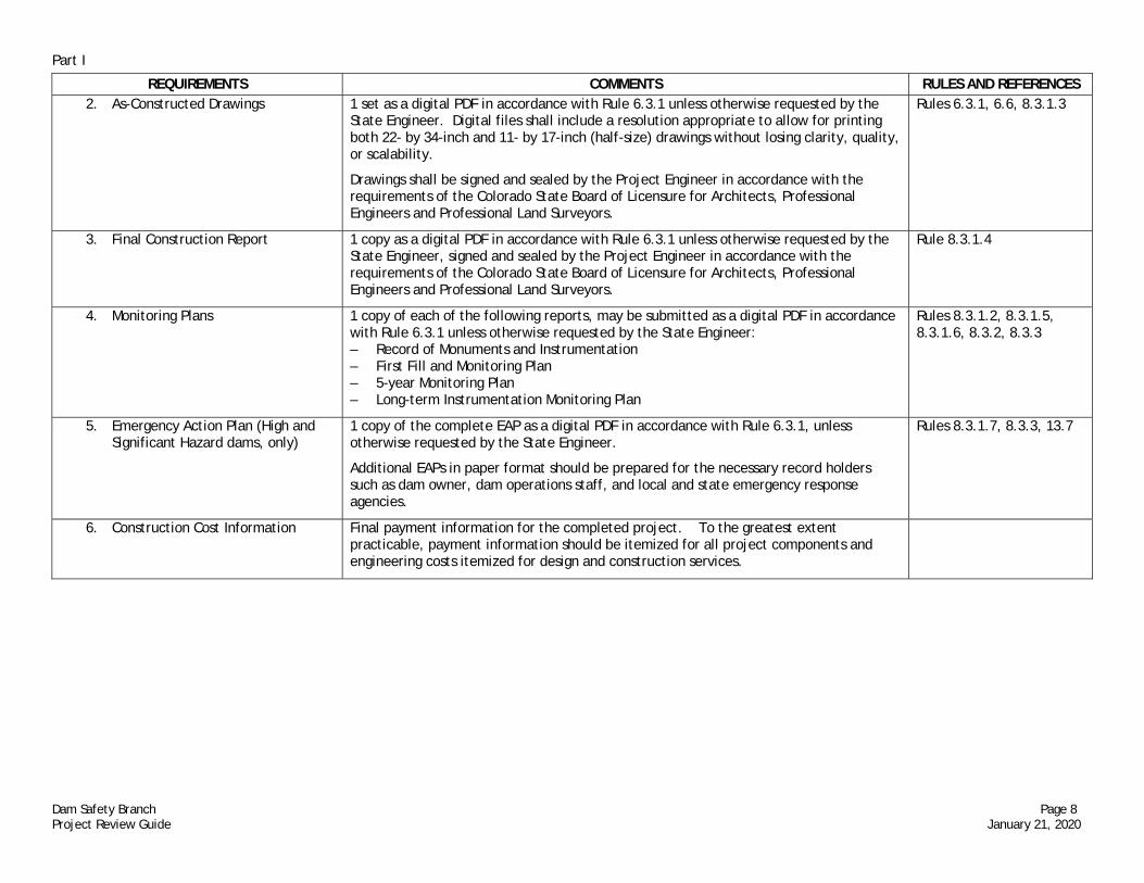
REQUIREMENTS COMMENTS RULES AND REFERENCES 2. As-Constructed Drawings 1 set as a digital PDF in accordance with Rule 6.3.1 unless otherwise requested by the
State Engineer. Digital files shall include a resolution appropriate to allow for printing both 22- by 34-inch and 11- by 17-inch (half-size) drawings without losing clarity, quality, or scalability.
Drawings shall be signed and sealed by the Project Engineer in accordance with the requirements of the Colorado State Board of Licensure for Architects, Professional Engineers and Professional Land Surveyors.
Rules 6.3.1, 6.6, 8.3.1.3
3. Final Construction Report 1 copy as a digital PDF in accordance with Rule 6.3.1 unless otherwise requested by the State Engineer, signed and sealed by the Project Engineer in accordance with the requirements of the Colorado State Board of Licensure for Architects, Professional Engineers and Professional Land Surveyors.
Rule 8.3.1.4
4. Monitoring Plans 1 copy of each of the following reports, may be submitted as a digital PDF in accordance with Rule 6.3.1 unless otherwise requested by the State Engineer: – Record of Monuments and Instrumentation – First Fill and Monitoring Plan – 5-year Monitoring Plan – Long-term Instrumentation Monitoring Plan
Rules 8.3.1.2, 8.3.1.5, 8.3.1.6, 8.3.2, 8.3.3
5. Emergency Action Plan (High and Significant Hazard dams, only)
1 copy of the complete EAP as a digital PDF in accordance with Rule 6.3.1, unless otherwise requested by the State Engineer.
Additional EAPs in paper format should be prepared for the necessary record holders such as dam owner, dam operations staff, and local and state emergency response agencies.
Rules 8.3.1.7, 8.3.3, 13.7
6. Construction Cost Information Final payment information for the completed project. To the greatest extent practicable, payment information should be itemized for all project components and engineering costs itemized for design and construction services.

Part II
Dam Safety Branch Page 9 Project Review Guide January 21, 2020
Part II - DESIGN AND TECHNICAL CRITERIA
REQUIREMENTS COMMENTS RULES AND REFERENCES II-A. Hazard Classification Report Guidelines for evaluating the potential consequences of failure and assigning the
appropriate hazard classification for dam projects in Colorado are described in the Colorado Dam Safety Branch (DSB) document “Guidelines for Hazard Classification” (January 2020, or latest revision). These Guidelines will be used by the DSB to check Hazard Classification Reports submitted for approval. The Hazard Classification Report must be signed and sealed by a professional engineer registered to practice in the State of Colorado. The Hazard Classification Report should be submitted to and approved by the DSB prior to commencing with other design work to ensure design criteria for the dam are appropriate for the hazard classification.
Rule 6.8.4, (DWR , 2020b), (DWR, 2020c)
1. General description of dam/reservoir and downstream inundation limits
The description should include the location of the dam and floodplain and a summary discussion of the floodplain land uses that will affect the hazard classification.
2. Detailed description of breach hydrograph estimation process
Procedures and models recommended for breach analysis of dam projects in Colorado are described in the DSB document “Guidelines for Dam Breach Analysis” (January 2020, or latest revision). These Guidelines will be used by the DSB to check dam breach studies submitted for approval. Spreadsheets and other computational aids included in the Guidelines are available on the DSB website.
3. Description of baseline conditions assumed for breach analysis
Baseline conditions include the starting water surface elevation, impounded volume in the reservoir, and the assumed failure mode. Also, any inflow into the reservoir included in the model shall be justified and documented. For normally dry flood control dams, the baseline condition is assumed to be the lowest normal operating level. Also, justify any principal spillway flows and downstream tributary inflows assumed for the base flood condition.
4. Detailed description of routing breach hydrograph downstream of dam
Procedures used to route the breach hydrograph downstream to estimate the hydraulic conditions at critical locations shall be satisfactorily documented. Examples of required information include: Names of all computer programs; hydrologic or hydraulic routing; 1-dimensional or 2-dimensional modeling; steady or fully dynamic unsteady flow analysis.
5. Tabulation of dam break and channel discharge parameters
Include any sensitivity analyses performed on the breach analysis and channel routing parameters.
6. Dam failure inundation maps showing hydraulics at critical locations
The map should include the location and alignment of the cross-sections used in the analysis, water surface elevation, arrival time of the initial and peak flood wave (from start of the dam breach), and average velocity in feet per second at each cross-section.
Rules 6.8.4, 13.7.1.6.1
7. Appropriate annotated cross-sections
Critical sections should illustrate any improved or habitable structures impacted by the dam failure flood wave and show the lowest habitable floor elevation.
Rule 13.7.1.6.1

Part II
Dam Safety Branch Page 10 Project Review Guide January 21, 2020
REQUIREMENTS COMMENTS RULES AND REFERENCES 8. Modeling parameters Hydraulic or hydrologic modeling parameters used in the breach hydrograph routing
model shall be documented. Examples include roughness coefficients, loss coefficients, and hydrologic routing parameters.
Rule 13.7.1.6.1
9. Conclusions and statement of recommended hazard classification
The recommended hazard classification for the dam shall be clearly stated. Rule 6.8.4
10. Digital Submittal Submit all digital files associated with the design for review including spreadsheets, computer models, mapping (including GIS shapefiles), and all other files used to support the recommended hazard classification.

Part II
Dam Safety Branch Page 11 Project Review Guide January 21, 2020
REQUIREMENTS COMMENTS RULES AND REFERENCES II-B. Hydrologic Hazard Evaluation
Under Rule 7.2, spillway IDF size is based on Hydrologic Hazard, which is defined in Rule 4.15 to mean overtopping (or other plausible hydrologic failure mode) dam failure consequences. Four categories of Hydrologic Hazard are provided. Prescriptive spillway IDF size for each category is given in Table 7.1.
DSB’s “Hydrologic Hazard Guidelines” discuss the analysis in detail. An overview of requirements is listed below
Rule 4.15, Rule 7.2, (DWR, 2020b), (DWR, 2020c), (DWR, 2020d), (DWR, 2020e), (Reclamation, 2015a), (USACE, 2016a), (USACE, 2018)
1. Overtopping Dam Breach Analysis (or other plausible hydrologic failure mode)
Overtopping dam breach analysis performed in HEC-RAS or DSS-WISE. Breach parameters are based on DSB’s “Guidelines for Dam Breach Analysis”. Starting reservoir WSEL is at the dam crest and all spillways are flowing at capacity. Other hydrologic-loading failure modes may be applicable on a case-by-case basis.
2. Floodwave routing The routed overtopping breach flood wave shall be modeled to a point downstream where no further damage (or incremental damage) is expected. Routing shall be performed to an appropriate level of detail as described in “Guidelines for Dam Breach Analysis”. HEC-RAS 2D and DSS-WISE are recommended.
3. Downstream concurrent flooding Because Hydrologic Hazard is determined for flood conditions, assumptions about downstream concurrent flooding must be made. Because such conditions are unpredictable, a sensitivity analysis is recommended.
4. Consequence Estimation Consequences should generally be determined using “RCEM – Reclamation Consequence Estimation Methodology”. Life loss consequences are the product of population-at-risk (PAR) and fatality rate.
Consequences may be determined based on total flood depth from the overtopping (or other plausible hydrologic failure mode) dam breach flood (including spillway flow) or based on incremental analysis between the overtopping (or other) flood (including spillway flow) and the spillway base flood immediately prior to dam failure
PAR may be determined using aggregate demographic data or by an inventory of actual structures.
Fatality rate is determined from RCEM Figure 3 (Little or No Warning) or Figure 4 (Adequate Warning). Judgement is required to make the case for warning adequacy (see RCEM manual). Fatality rates are graphed as a function of flood severity, measured in depth x velocity (DV). Two methods are generally recommended for extracting DV and determining fatality rates: 1) point DV at each structure to determine structure-by-structure fatality rate and life loss or 2) reach-average DV, generally used with aggregate demographic PAR data. Life loss is estimated as the sum of all structure or reach life loss over the entire flood limits.
Economic or other damage should be evaluated where flooding is expected at uninhabited structures, i.e., PAR is zero (see DSB’s “Guidelines for Hazard Classification).
Rule 7.2.2, (DWR, 2020b), (Reclamation, 2015a)

Part II
Dam Safety Branch Page 12 Project Review Guide January 21, 2020
REQUIREMENTS COMMENTS RULES AND REFERENCES 5. Spillway Sizing Prescriptive IDF size based on Hydrologic Hazard category is given in Table 7.1, Rule 7.2.
Development of design storms using Colorado’s Regional Extreme Precipitation Study (REPS) tools is discussed below in II-C (Hydrology Report).
The minimum spillway IDF size allowable under Table 7.1, Rule 7.2, is the flood from the 1% AEP storm for Low Hydrologic Hazard category. From a design standpoint, spillway size is increased until the magnitude of the design storm is adequate for Hydrologic Hazard category or until incremental Hydrologic Hazard is decreased.
Rule 7.2.1 (DWR, 2020e)
6. Hydrologic Risk On a case-by-case basis spillway size may be determined by hydrologic risk analysis as an alternative to the prescriptive IDF criteria in Table 7.1, Rule 7.2, in order to select an IDF that is between prescriptive sizes (e.g. between 0.01% AEP and PMP), such that the product of probability of overtopping dam failure and its consequences (life loss) is an acceptably remote risk by dam safety industry standards
Rule 7.2.1
7. Early Warning It may be possible to reduce Hydrologic Hazard by early warning systems including monitoring, emergency planning, and emergency action plan exercises. Any proposed early warning system must be prepared in a written plan, reviewed by emergency managers, and must be reviewed and approved by the State Engineer and must be included in the dam’s EAP and exercised annually.
(Refer to II-K.5)
II-C. Hydrology Study
The Inflow Design Flood (IDF) size is based on Hydrologic Hazard as described in Table 7.1, Rule 7.2. The IDF hydrograph or peak flow may be generated using rainfall-runoff modeling or by flood frequency analysis.
Guidelines for evaluating the Inflow Design Flood (IDF) by rainfall runoff methods for a dam project in Colorado are described in the DSB document “Hydrologic Basin Response Parameter Estimation Guidelines” (2008, or latest revision). These Guidelines will be used by the DSB to check the IDF submitted for approval. The Hydrology Report must be signed and sealed by a professional engineer registered to practice in the State of Colorado. The Hydrology Report may be submitted to and approved by the DSB prior to commencing with other design work to ensure design criteria for the spillway are commensurate with the Hydrologic Hazard classification.
Rule 7.2, (DWR, 2008), (DWR, 2020b), (DWR, 2020e) (Reclamation, 2015c) (USACE, 1993) (USACE, 1994b) (USACE, 2009) (USGS, 2018)
1. Topographic map of dam and tributary basin
Rule 13.7.1.6.1
a) Location of the dam and drainage basin map
Watershed shapefiles should be provided in WGS84 format when applicable for upload into MetPortal Watershed Precipitation Frequency Interface.
Application for Review of Plans and Specifications for the Construction of or Enlargement of a Dam and Reservoir
b) Drainage area (square miles)

Part II
Dam Safety Branch Page 13 Project Review Guide January 21, 2020
REQUIREMENTS COMMENTS RULES AND REFERENCES 2. Report Components The components described in this section pertain to IDF development using rainfall-runoff
methods. Rule 6.8.5
a) Basin Description including topography, geology, vegetative cover, identification of natural watercourse, and elevation of the Dam Crest
Rule 7.2.6
b) Provide design storm rainfall data and temporal distributions, and atmospheric moisture factor
By Rule 7.2 prescriptive IDFs are deterministic (PMP) or probabilistic (0.01% AEP or 1% AEP) depending on Hydrologic Hazard category.
Colorado’s Regional Extreme Precipitation Study (REPS) PMP Tool shall be used to develop PMP. MetPortal Precipitation Frequency (PF) Tool shall be used to develop probabilistic storms. DSB’s “Guidelines for Use of REPS Rainfall Estimation Tools” lists the specific storms that must be analyzed to determine the critical case in terms of maximum reservoir elevation.
Document sub-basin analysis and spatial patterns if used. REPS guidelines discuss these topics.
Submittals for PMP storms shall include graph of temporal distributions for all analyzed storms, summary table of all inter-duration PMP estimates (e.g. 1-hr, 2-hr, 3-hr, etc.) and controlling historical storms (found in each PMP point shapefile), PMP-factors (IPMF, GTF and MTF), and a MetPortal PF Tool graph showing equivalent AEP of PMP. Provide StreamStats or GIS derived basin shapefile and/or REPS PMP Tool geodatabase (provided as output from PMP tool).
Submittals for PF storms shall include the MetPortal Precipitation Frequency table, with uncertainty bounds, and graph of the applicable temporal pattern for each Storm Type (LS, MEC, MLC). Basin shapefile in WGS84 geographic coordinates (lat/long) and csv format output files from MetPortal shall be submitted.
Once the appropriate REPS rainfall depths have been determined, an atmospheric moisture factor of 1.07 must be applied to account for expected future increases in temperature and associated increases in atmospheric moisture availability, prior to calculating runoff. This factor can easily be applied in HEC-HMS as a precipitation ratio.
Rainfall may also be determined using Site Specific Extreme Precipitation Study (refer to II-D)
Rules 7.2.3, 7.2.4, (DWR, 2020e - REPS Volume II, REPS Volume III, Guidelines for Use of Regional Extreme Precipitation Study (REPS) Rainfall Estimation Tools)

Part II
Dam Safety Branch Page 14 Project Review Guide January 21, 2020
REQUIREMENTS COMMENTS RULES AND REFERENCES c) Summary of method used to
develop unit hydrograph and basis for selection of parameters
Procedures for selecting basin response parameters and developing the runoff from excess precipitation are presented in the DSB document “Hydrologic Basin Response Parameter Estimation Guidelines” (May 2008).
Spreadsheets and other computational aids included in the Guidelines for calculating basin runoff are available on the DSB website.
USBR dimensionless UHs are generally recommended; however, other industry standard methods for rainfall-runoff transformation, such as Clark Unit Hydrograph or HEC-RAS 2D, may be acceptable and should be discussed with DSB in advance.
(DWR, 2008), (USACE, 2020b)
(1) For Reclamation Dimensionless Unit Hydrographs and S-Graphs, identify all variables and provide a basis for the selection of all parameters used to develop the unit hydrograph
Variables/Parameters include:
Area (A), Length of longest flow path (L), Length to point opposite basin Centroid (Lca), Average Slope (S), Lumped flow resistance parameter (Kn), Lag Time (Lag)
(2) For Clark Unit Hydrograph, identify all variables and provide a basis for the selection of all parameters used to develop the unit hydrograph
Variables/Parameters include:
Area (A), Length of longest flow path (L), Length to point opposite basin Centroid (Lca), Average Slope (S), Time of Concentration (Tc), Effective Impervious Area (RTIMP), Storage Coefficient (R), Provide basis for selected Time-Area Relation
(3) For HEC-RAS 2D derived Unit Hydrograph, provide rainfall excess calculations and appropriate HEC-RAS files
HEC-RAS files include: delineated basin, terrain, land cover and DSS depression fill files. For analyses performed using equivalent software to HEC-RAS, provide input and output files with suitable level of description and discussion.
d) Detailed description of rainfall losses including basis for selection of parameters – include soils data to support selected parameters
A spreadsheet template for calculating rainfall losses based on detailed soil surveys obtained through the NRCS Web Soil Survey is available on the DSB website. SSURGO soil survey data should be used where available. Unpublished soil surveys for National Forest lands should be obtained directly from the soil scientist in each National Forest.
(DWR, 2008)
Part II
Dam Safety Branch Page 15 Project Review Guide January 21, 2020
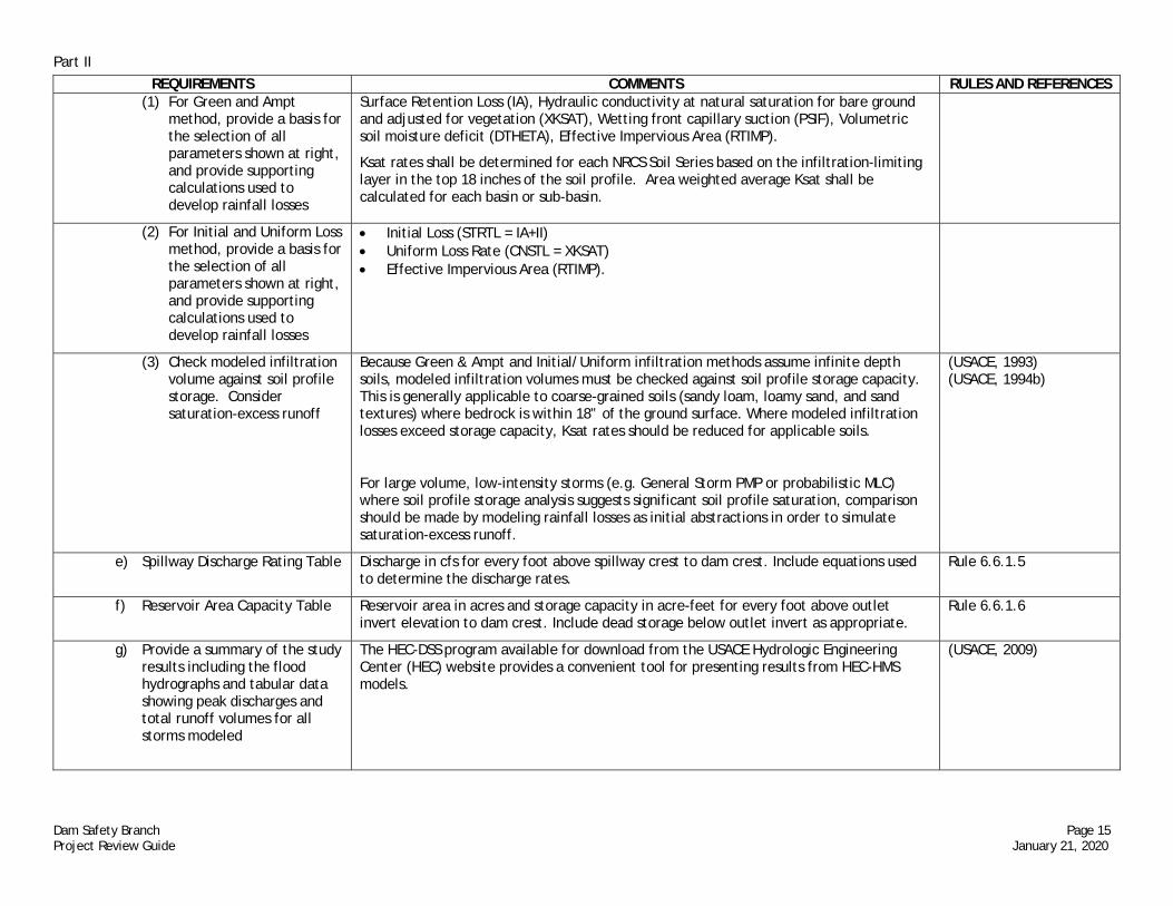
REQUIREMENTS COMMENTS RULES AND REFERENCES (1) For Green and Ampt
method, provide a basis for the selection of all parameters shown at right, and provide supporting calculations used to develop rainfall losses
Surface Retention Loss (IA), Hydraulic conductivity at natural saturation for bare ground and adjusted for vegetation (XKSAT), Wetting front capillary suction (PSIF), Volumetric soil moisture deficit (DTHETA), Effective Impervious Area (RTIMP).
Ksat rates shall be determined for each NRCS Soil Series based on the infiltration-limiting layer in the top 18 inches of the soil profile. Area weighted average Ksat shall be calculated for each basin or sub-basin.
(2) For Initial and Uniform Loss method, provide a basis for the selection of all parameters shown at right, and provide supporting calculations used to develop rainfall losses
Initial Loss (STRTL = IA+II) Uniform Loss Rate (CNSTL = XKSAT) Effective Impervious Area (RTIMP).
(3) Check modeled infiltration volume against soil profile storage. Consider saturation-excess runoff
Because Green & Ampt and Initial/Uniform infiltration methods assume infinite depth soils, modeled infiltration volumes must be checked against soil profile storage capacity. This is generally applicable to coarse-grained soils (sandy loam, loamy sand, and sand textures) where bedrock is within 18” of the ground surface. Where modeled infiltration losses exceed storage capacity, Ksat rates should be reduced for applicable soils.
For large volume, low-intensity storms (e.g. General Storm PMP or probabilistic MLC) where soil profile storage analysis suggests significant soil profile saturation, comparison should be made by modeling rainfall losses as initial abstractions in order to simulate saturation-excess runoff.
(USACE, 1993) (USACE, 1994b)
e) Spillway Discharge Rating Table Discharge in cfs for every foot above spillway crest to dam crest. Include equations used to determine the discharge rates.
Rule 6.6.1.5
f) Reservoir Area Capacity Table Reservoir area in acres and storage capacity in acre-feet for every foot above outlet invert elevation to dam crest. Include dead storage below outlet invert as appropriate.
Rule 6.6.1.6
g) Provide a summary of the study results including the flood hydrographs and tabular data showing peak discharges and total runoff volumes for all storms modeled
The HEC-DSS program available for download from the USACE Hydrologic Engineering Center (HEC) website provides a convenient tool for presenting results from HEC-HMS models.
(USACE, 2009)

Part II
Dam Safety Branch Page 16 Project Review Guide January 21, 2020
REQUIREMENTS COMMENTS RULES AND REFERENCES h) Comparison to Streamstats
Q100 & reasonableness checks For rainfall-runoff model evaluation, MetPortal 1% AEP storms (LS, MEC & MLC) should be run in HEC-HMS and the critical peak flow compared to USGS StreamStats Q100 for reasonableness. Other reasonableness checks should include:
Comparison to basin or neighboring basin stream gage frequency analysis and floods of record.
Comparison to regional peak flow envelope curves for the basin area size. Comparison to regional paleo-hydrology studies:
https://www.usgs.gov/centers/co-water/science/flood-database-colorado?qt-science_center_objects=0#qt-science_center_objects
Comparison to reports of historical floods in the basin or neighboring basins.
(DWR, 2020e)
i) Provide a discussion of sensitivity analyses performed on key parameters used to develop the basin lag time and the rainfall losses
At a minimum the sensitivity analysis should consider the published ranges of Kn values for a given watershed and storm type.
3. Flood Frequency Hydrology Study This section describes IDF development using flood frequency methods.
Flood frequency studies should consider the following:
Availability of stream gauge data and introduction of uncertainty by use of regional regression data for ungauged basins;
Appropriate period of record (AEP of less than 0.005 generally requires augmentation of annual peak flood values with precipitation and/or Paleoflood data);
Climate change; Mixed distributions (rainfall and snowmelt events); and Flow regime change due to flow regulation, urbanization and changing land use
practices.
Rules 7.2.3.2, 7.2.5, (USGS, 2018)
4. Digital Submittal The hydrology report and IDF Analysis should include all computer models, spreadsheets, tabulated data, mapping, and other materials used to compute the precipitation and routed runoff for all storms modeled.

Part II
Dam Safety Branch Page 17 Project Review Guide January 21, 2020
REQUIREMENTS COMMENTS RULES AND REFERENCES II-D. Site Specific Extreme
Precipitation Study
A Site Specific Extreme Precipitation Study may be used where generalized studies, such as Colorado REPS, do not accurately account for local climate and terrain due to interpolation, envelopment, etc. Site Specific Extreme Precipitation Studies should follow current standard of practice as defined by REPS Final Report Volumes II (PMP) and III (PF).
Rule 7.2.3.3, (DWR, 2020e)
1. Notice of Scope of Work /Kick-off Meeting
Prior to commencement of a Site Specific Extreme Precipitation Study the dam owner should provide notice to the State Engineer detailing the proposed scope of work. This notice will provide the State Engineer with the opportunity to provide guidance prior to the start of work and to authorize pursuit of the study. Once a consulting meteorologist is selected, it is recommended that the consultant schedule a kick-off meeting with the State Engineer’s Office DSB to discuss the scope, State Engineer guidance, and anticipated challenges in the study.
2. Independent Peer Review An independent peer review of the Site Specific Extreme Precipitation Study must be performed on behalf of the State Engineer, and must be contractually independent from the consultant performing the study. All peer review comments shall be submitted to the SEO along with responses from the lead meteorologist and with concurrence from the peer reviewer demonstrating that the comments were satisfactorily addressed.
3. Experience Site specific extreme precipitation studies for dam safety applications should be performed by a full member of the American Meteorological Society (AMS) or an AMS Certified Consulting Meteorologist with at least 5 years of experience in Probable Maximum Precipitation or Extreme Precipitation Frequency analysis.

Part II
Dam Safety Branch Page 18 Project Review Guide January 21, 2020
REQUIREMENTS COMMENTS RULES AND REFERENCES II-E. Geotechnical/Geological A complete geotechnical and geological investigation must be conducted in sufficient
detail to support the structural design for all new, rehabilitated, or enlarged dams. The extent of the required investigation, testing, and evaluation varies with the hazard classification, size, and complexity of the dam; however, it is intended that an adequate level of investigation and analysis is conducted for every dam in accordance with modern standards of engineering practice. The Geotechnical Report submitted for approval must be signed and sealed by a Professional Engineer.
All investigations requiring drilling or excavation within 200 feet of existing dams must be reviewed and approved by the DSB prior to the field work. Subsurface investigation plans shall be prepared in accordance with the Subsurface Investigation Plans Requirements and Guidance (DWR, 2020f). Feasibility level investigations and reports are not sufficient for design purposes.
Rules 7.3, 7.4 (DWR, 2020f). (FEMA, 2005b) (FEMA, 2011), (FERC, 2006), (FERC, 2011), (Reclamation, 1987a), (Reclamation, 2011a), (Reclamation, 2011b), (Reclamation, 2011c), (Reclamation, 2012a), (Reclamation, 2012b), (Reclamation, 2012c), (Reclamation, 2012e), (Reclamation, 2013), (Reclamation, 2014a) (Reclamation, 2014b), (Reclamation, 2014e), (Reclamation, 2014f), (Reclamation, 2015b), (Reclamation, 2015c), (Reclamation, 2018a), (USACE, 2003), (USACE, 2007), (USACE, 2016b)
1. High and Significant Hazard dams
a) Geotechnical/geological investigation and analyses
(DWR, 2020f)
(1) Geological assessment Provide a thorough geological assessment of the dam and reservoir site, including evaluation of the regional geologic setting; local and site geology; geologic suitability of the dam foundation and reservoir area; slope stability and seepage potential of the reservoir and abutment areas; seismic history and potential, including areas of industrial drilling that utilize injection methods and other subsurface activities ; and other potential geological hazards posed by the site and proposed construction. Assess the potential for hillsides and rock formations around the reservoir perimeter to become unstable or for existing faults to become mobilized as a consequence of construction of the dam. The effects of reservoir leakage must be thoroughly investigated and the adverse effects mitigated.
Rules 7.3.1, 7.3.2, (FERC, 2006) (Reclamation, 2012a)

Part II
Dam Safety Branch Page 19 Project Review Guide January 21, 2020
REQUIREMENTS COMMENTS RULES AND REFERENCES (2) Seismicity The study shall determine and justify the appropriate seismic parameters to be used for
design. The seismic assessment shall also address the stability of appurtenant structures to the dam during the design earthquake. Deterministic and probabilistic methods are both acceptable.
(FEMA, 2005b), (Reclamation, 2015b), (Reclamation, 2015c), (USACE, 2007), (USACE, 2016b)
(3) Field investigation A sufficient number of soil and rock samples must be obtained from the field investigation to provide a statistically meaningful representation of the materials to be evaluated.
Rules 7.3.1, 7.3.3, 7.3.4
(i) Foundation investigation
The subsurface exploration shall provide information required to characterize the foundation soils, estimate the permeability of foundation soils and rock, evaluate the depth and geologic classification of the bedrock, estimate foundation excavatability, characterize the competency of the foundation under the dam and appurtenant structures, and assess the need for and anticipated extent of any treatment program(s) required to adequately stabilize the foundation and/or control seepage.
Rules 6.8.7, 7.3, (Reclamation, 2012b), (Reclamation, 2012e), (Reclamation, 2014d)
(ii) Borrow investigation
Identify the location(s) and availability of enough suitable borrow materials to construct the dam, and evaluate the need to blend or otherwise process borrow materials.
Rule 7.3.4.5, Reclamation, 2012e),
(4) Laboratory testing A sufficient number of laboratory tests must be performed for each material included in the dam or foundation to support the selected design criteria. Laboratory tests must include index testing required to classify all soils in accordance with the Unified Soil Classification System (USCS).
The test program should allow direct determination of the drained shear strength and undrained shear strength parameters needed for slope stability and bearing capacity analyses. Simple Direct Shear tests performed at conventional strain rates without pore pressure measurements are not appropriate for determining the drained strength of soils that do not drain quickly.
Consolidation/swell tests should be performed on undisturbed and/or remolded samples, as appropriate, of all soils or rock that could affect the stability of the dam or appurtenant structures through settlement or heave. Test conditions should reflect the loading conditions anticipated for the soils.
Foundation soils and soils to be used for embankment fill must be tested to evaluate the potential for dispersive behavior and alkali-aggregate reaction with concrete.
Foundation rock must be evaluated for intact strength and joint/bedding strength.
Permeability tests for foundation, abutment, and embankment materials should be conducted under laboratory conditions that represent the anticipated loading conditions for the materials. Permeability tests should be conducted on both undisturbed and remolded samples, as appropriate for the dam design.
A sufficient number of lab tests should be performed to permit complete characterization of the envelope of engineering properties of each material affecting the construction of
(ASTM D2487)

Part II
Dam Safety Branch Page 20 Project Review Guide January 21, 2020
REQUIREMENTS COMMENTS RULES AND REFERENCES the dam. Laboratory test results should be tabulated and presented in the Geotechnical Report for easy reference to each test result with respect to the dam element or material zone represented by the test.
(5) Stability analyses All dams must be shown to meet the requirements for minimum factor of safety against slope and foundation failure both during construction and under all conditions of reservoir operation. Proper shear strength parameters should be used for the various loading conditions and materials, depending on the rate of loading and the anticipated drainage properties and conditions.
Rule 7.4.2.5, (FERC, 2006), (Reclamation, 1987a), (Reclamation, 2011a), (Reclamation, 2011c), (Reclamation, 2012a), (USACE, 2003), (USACE, 2005)
(6) Seepage analyses Seepage through the embankment, abutments, foundation, and under and around appurtenances shall be analyzed for design of seepage controls to prevent internal erosion, piping, and external sloughing and to provide for adequate stability of the dam. Results of the seepage analyses will form the basis for design of the filters, drain blankets, toe drain, uplift resistance, etc. Geotechnical analyses should include filter compatibility analysis on all material boundaries in the dam and foundation that are subject to seepage flows. Unfiltered seepage or seepage that exits the dam or foundation uncontrolled is not acceptable.
Rule 7.4.1.4, (FEMA, 2011), (FERC, 2006), (FERC, 2011), (Reclamation, 2011b), (Reclamation, 2012a), (Reclamation, 2014b), (Reclamation, 2014e)
(7) Freeboard analysis The appropriate amount of normal and minimum freeboard to protect the embankment dam and appurtenances shall be analyzed for design of the spillway features and slope protection to mitigate wind-generated waves and reservoir setup to prevent dam overtopping and/or slope erosion.
(Reclamation, 2012c)
(8) Upstream slope erosion protection analysis
Embankments shall be protected against external erosion and slope protection for wave action may be required on the entire upstream slope of the dam. Analysis should be performed to determine the wind-generated wave and reservoir setup erosion potential and to select, design, and specify the necessary slope protection materails.
(Reclamation, 2013), (Reclamation, 2014a)
b) Geotechnical Report The Geotechnical Report presents the results and conclusions of all field investigations and field and laboratory testing. The report may also include technical analyses performed to develop the project design criteria.
Rules 6.8.7, 7.3, 7.4.1,

Part II
Dam Safety Branch Page 21 Project Review Guide January 21, 2020
REQUIREMENTS COMMENTS RULES AND REFERENCES 2. Low Hazard dams Requirements for field investigations, laboratory testing, analysis, and reporting for Low
Hazard dams are less stringent than the requirements for High and Significant Hazard dams.
Results of all investigations, testing, and analyses shall be presented in the Geotechnical Report.
Rule 7.3.4.2
3. NPH dams Requirements for field investigations, laboratory testing, analysis, and reporting for NPH dams are less stringent than the requirements for Low Hazard dams.
Results of all investigations, testing, and analyses shall be presented in the Geotechnical Report.
Rule 7.3.4.2
4. Digital Submittal The geotechnical report should include a digital file of all tabulated field and lab test results, spreadsheets, computer model results, and other calculations for evaluating the stability and safety of the dam, dam foundation, spillway(s), and appurtenant structures.

Part II
Dam Safety Branch Page 22 Project Review Guide January 21, 2020
REQUIREMENTS COMMENTS RULES AND REFERENCES II-F. Dam Design Requirements
1. Embankment dams Embankment dam designs shall be based on acceptable criteria for slope stability, deformation, seepage control and internal drainage, embankment geometry, material placement and compaction, and riprap or other erosion protection.
Rules 7.3, 7.4 (FEMA, 2005a) (FEMA, 2011), (FERC, 2006), (FERC, 2011), (FERC, 2017), (Reclamation, 1987a), (Reclamation, 2011a), (Reclamation, 2011b), (Reclamation, 2011c), (Reclamation, 2012a), (Reclamation, 2012b), (Reclamation, 2012c), (Reclamation, 2012d), (Reclamation, 2012e), (Reclamation, 2013), (Reclamation, 2014a) (Reclamation, 2014b), (Reclamation, 2014d), (Reclamation, 2014e), (Reclamation, 2014f), (Reclamation, 2014g), (Reclamation, 2015a), (Reclamation, 2015c), (Reclamation, 2018a),

Part II
Dam Safety Branch Page 23 Project Review Guide January 21, 2020
REQUIREMENTS COMMENTS RULES AND REFERENCES 2. Concrete dams Concrete dam designs shall be based on acceptable criteria for overturning and sliding
stability, crest access and geometry, foundation preparation, overtopping protection, internal drainage, and control of uplift pressures.
RCC dam designs shall include the design provisions for concrete dams and additional provisions pertinent to roller-compacted concrete including mix design testing, crack control, bonding layer treatments, constructability, interior drainage, field quality control testing, etc.
Rule 7.5 (ACI, 2006), (ACI, 2016), (ACI, 2019), (FERC, 2016), (FERC, 2017), (FERC, 2018), (PCA, 2016), (Reclamation 1976), (Reclamation, 1977a), (Reclamation, 1977b), (Reclamation, 1987a), (Reclamation, 2014d) (Reclamation, 2015c), (Reclamation, 2017b), (USACE, 1994a), (USACE, 1995), (USACE, 2000), (USACE, 2016c)
3. Seismicity All High and Significant Hazard dams must be analyzed and designed for seismic stability. Rule 7.6, (FEMA, 2005b), (FERC, 2006), (Reclamation, 2015b), (Reclamation, 2015c), (USACE, 2007), (USACE, 2016a)

Part II
Dam Safety Branch Page 24 Project Review Guide January 21, 2020
REQUIREMENTS COMMENTS RULES AND REFERENCES II-G. Spillway Design Requirements
The spillway(s) should be capable of passing the IDF in accordance with Rule 7.2 to prevent overtopping of the dam and be capable of withstanding the sustained forces of the IDF without causing or experiencing unacceptable damage. Spillway design is a complex process that is of critical importance to the safe operation of a dam. The spillway should be designed to the corresponding hydrologic hazard and safety route the critical rainfall noted in Table 7.1 of Rule 7.2. Based on the consequence estimation method, the spillway size will be deemed acceptable when the spillway size meets or exceeds the IDF requirements of Table 7.1 for a given hydrologic hazard category. Inadequate spillways are one of the leading causes of dam failure.
Rules 4.15, 7.2, 7.8.1 (Brater, et.al., 1996), (Chow, 1959), (DWR, 2020d), (DWR, 2020e), (Falvey, 1980), (Falvey, 2003), (FEMA, 2005a), (FEMA, 2010), (FEMA, 2014), (FERC, 2015), (Lux, 1985), (Paxson, 2011), (Reclamation, 1987a), (Reclamation, 1987b), (Reclamation, 1990), (Reclamation, 2012c), (Reclamation, 2014h), (Reclamation, 2014i), (Reclamation, 2015c) (Tullis, 1995), (USACE, 1989), (USACE, 1993), (USACE, 1994b), (USACE, 1995), (USACE, 2000), (USACE, 2005), (USACE, 2016a), (USACE, 2016c) (USACE, 2018), (USGS, 2018), (USSD, 2002), (USSD, 2006)

Part II
Dam Safety Branch Page 25 Project Review Guide January 21, 2020
REQUIREMENTS COMMENTS RULES AND REFERENCES 1. General Policies Spillway structures founded on the embankment of an existing dam and require
overtopping flow are discouraged for new construction, however they will be considered on a case-by-case basis when no other spillway alternatives are feasible. An overtopping protection design shall be required that demonstrates the IDF can be safety routed through the spillway.
Designs that include an embankment overtopping spillway are discouraged for new embankment dams.
Pipe or conduit spillways that serve as the only spillway for the dam are not acceptable. If a pipe spillway is considered the only option, a formal waiver request must be submitted. A permitted pipe spillway shall include a trash rack to prevent clogging and shall be accessible for cleaning or be designed as a self-cleaning type structure. Trash racks should be designed to withstand permissible water velocities and hydrostatic pressure assuming that the trash rack is 50% clogged with debris.
Rules 7.8.1.6, 7.8.1.4
2. Design Considerations Rule 7.8.1
a) Control section Spillway flow control sections should be stable at a fixed location and should not become submerged by downstream conditions during any discharge. For open channel spillways, weir equations are not valid, and the backwater must be taken into account during the spillway capacity and rating curve development. Due to the significant impact that roughness coefficients have on the spillway rating curve development, the analysis must include a sensitivity analysis justifying the chosen roughness coefficient(s).
b) Starting water surface The starting water surface elevation when routing the IDF shall be the emergency spillway crest.
Rule 7.8.1.1
c) Control weir If the spillway flow control section includes a weir, the profile of the weir should be designed to prevent excessive negative pressures and cavitation on the downstream face of the weir. If the design parameters chosen require an aerated nappe, air demand and venting calculating shall be provided.
d) Fuse Plug and Other Dump-Type Spillways
Fuse plugs, fuse gates, and erodible section or dynamic and/or mechanical dump type spillways may be allowed on a case-by-case basis. Spillway activation must be initiated by the flood and must not require human and/or mechanical/electrical intervention to activate.
(Reclamation, 1987b)

Part II
Dam Safety Branch Page 26 Project Review Guide January 21, 2020
REQUIREMENTS COMMENTS RULES AND REFERENCES e) Overtopping spillways on dam
embankments Overtopping protection for existing embankment dams may be used to safely route the IDF only where no other alternatives are feasible. The design of overtopping protection shall be based on the principles provided in Overtopping Protection for Dams (P-1015, FEMA, 2014). Overtopping spillway designs an existing dam must give strong consideration to the potential risk of failure of the protection system, which could quickly lead to a full breach of the dam. A major PFM with overtopping protection is if the protection fails during a flood event and the underlying embankment is exposed, erosion and headcutting in the embankment materials could progress rapidly and lead to a breach of the dam. Types of overtopping protection for embankment dams listed in Overtopping Protection for Dams require detailed analysis of all potential failure modes for the dam and appurtenant features for both the existing (baseline) conditions and for the proposed modified conditions.
For existing spillway designs that have inadequate spillway sizing, the common methods for accommodating large spillway floods are increasing reservoir storage by raising the dam crest or increasing release capability by increasing the spillway discharge capacity. Instances where these methods cannot be applied and overtopping spillways are considered, the new design approaches must be developed that allow for the dam to be safely overtopped as discussed above.
Rule 7.8.1.6, (FEMA, 2014)
f) Spillway Channel/Chute Protection
The design of the spillway and channel protection shall consider the duration and volume of frequent flows. Earth spillways shall be protected from frequent flow by a service spillway that carries the majority of normal reservoir inflows, or shall be designed to pass frequent flows without sustaining damage. There are various methods that can be utilized to protect the spillway channel from erosion while routing the IDF for the dam. Some special considerations for each are provided below:
All spillway channels not protected by concrete lining or constructed in sound rock shall have at least one concrete erosion control beam across the channel at the control section to establish the spill elevation. Earthen spillways shall include an erosion analysis to demonstrate that the spillway can safely route the IDF without initiating an uncontrolled release of the reservoir. Additional erosion control beams or other erosion control measures may be required based on the results of the erosion analysis.
Spillway chutes designed for supercritical flow shall be designed to either eliminate standing or cross-wave problems or have sufficient freeboard to contain such phenomena. An appropriate energy dissipation structure must be included to control the hydraulic jump at the end of the spillway.

Part II
Dam Safety Branch Page 27 Project Review Guide January 21, 2020
REQUIREMENTS COMMENTS RULES AND REFERENCES Grass cover in an earthen spillway channel can significantly increase its resistance
to erosion. Earthen spillways shall include a revegetation plan that includes soil amendments, and a seed mix design appropriate for the specific climate. If a spillway relies on grass cover for erosion resistance, the construction will not be considered complete until the grass cover has been established for one year.
Riprap protected channels should include a layer of granular filter bedding between the riprap and subgrade to prevent loss of supporting subgrade material during flow events. Geotextile fabrics are discouraged due to durability, constructability, and slope stability issues that they present.
When a hydraulic model is utilized to predict erosive forces created within the spillway and to develop spillway freeboard requirements, the analysis shall consider the effect of the selected roughness coefficient(s) on the necessary erosion protection and freeboard and include a sensitivity analysis justifying the chosen parameters.
The formation of a hydraulic jump within an earthen spillway channel poses a significant erosive threat to the channel. Earthen spillway channels should be designed to prevent supercritical flow and hydraulic jumps. If supercritical flow is unavoidable, adequate energy dissipation must be provided.
For high velocities in concrete channels, special designs are required to mitigate cavitation, control joint deflection, and provide subgrade/backfill protection against hydraulic jacking and removal of underlying soils. Required provisions to mitigate these factors include, but are not limited to, articulated/shingled construction joints with waterstop. Reinforced concrete spillway chutes shall be designed to reduce/eliminate uplift pressure with the use of adequate subgrade/backfill drainage and shall be anchored to the foundation to provide an adequate safety factor against sliding and buoyancy with the use of rock anchors, soil nails, bulb anchors or similar means.
Spillway channel side slopes should be stable during the design event to prevent spillway channel blockage due to a slope failure.
Channel lining materials should be designed to pass normal operations and maximum spillway design flows safely through the spillway without erosion or head cutting scour in the vicinity of the dam. Design engineer to provide necessary documentation on proposed spillway lining materials and spillway foundation conditions to support the spillway design. Potential failure modes associated with the proposed spillway concepts should be evaluated to support the spillway design and analysis should be performed as required to confirm corresponding dam safety risks.
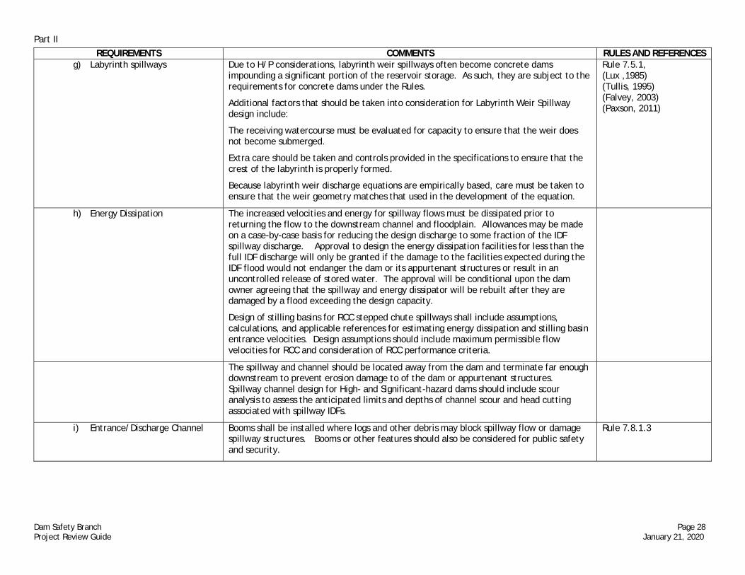
Part II
Dam Safety Branch Page 28 Project Review Guide January 21, 2020
REQUIREMENTS COMMENTS RULES AND REFERENCES g) Labyrinth spillways Due to H/P considerations, labyrinth weir spillways often become concrete dams
impounding a significant portion of the reservoir storage. As such, they are subject to the requirements for concrete dams under the Rules.
Additional factors that should be taken into consideration for Labyrinth Weir Spillway design include:
The receiving watercourse must be evaluated for capacity to ensure that the weir does not become submerged.
Extra care should be taken and controls provided in the specifications to ensure that the crest of the labyrinth is properly formed.
Because labyrinth weir discharge equations are empirically based, care must be taken to ensure that the weir geometry matches that used in the development of the equation.
Rule 7.5.1, (Lux ,1985) (Tullis, 1995) (Falvey, 2003) (Paxson, 2011)
h) Energy Dissipation The increased velocities and energy for spillway flows must be dissipated prior to returning the flow to the downstream channel and floodplain. Allowances may be made on a case-by-case basis for reducing the design discharge to some fraction of the IDF spillway discharge. Approval to design the energy dissipation facilities for less than the full IDF discharge will only be granted if the damage to the facilities expected during the IDF flood would not endanger the dam or its appurtenant structures or result in an uncontrolled release of stored water. The approval will be conditional upon the dam owner agreeing that the spillway and energy dissipator will be rebuilt after they are damaged by a flood exceeding the design capacity.
Design of stilling basins for RCC stepped chute spillways shall include assumptions, calculations, and applicable references for estimating energy dissipation and stilling basin entrance velocities. Design assumptions should include maximum permissible flow velocities for RCC and consideration of RCC performance criteria.
The spillway and channel should be located away from the dam and terminate far enough downstream to prevent erosion damage to of the dam or appurtenant structures. Spillway channel design for High- and Significant-hazard dams should include scour analysis to assess the anticipated limits and depths of channel scour and head cutting associated with spillway IDFs.
i) Entrance/Discharge Channel Booms shall be installed where logs and other debris may block spillway flow or damage spillway structures. Booms or other features should also be considered for public safety and security.
Rule 7.8.1.3

Part II
Dam Safety Branch Page 29 Project Review Guide January 21, 2020
REQUIREMENTS COMMENTS RULES AND REFERENCES j) Blockage Spillways subject to snow and ice conditions shall be evaluated for blockage during the
spring. Placing the spillway on the sunny side of the reservoir or otherwise minimizing snow drift formation in the spillway can help mitigate the problem. Potential for weathering of the approach channel, chute, and energy dissipation system should be considered and appropriate protection provided.
k) Spillway Right-Of-Way The dam owner must possess either title or an easement for the spillway channel from the high water line in the reservoir to the natural channel including the stilling basin downstream of the dam.
Rule 7.8.1.2
l) Drop Inlet Service Spillways Drop inlet service spillways may be incorporated into outlet works for the dam. Special considerations for this type of design include ventilation and sizing of the conduit to prevent pressurization and/or surging of flow. The conduit downstream of the spillway entrance must have capacity for both spillway flows and maximum outlet releases without pressurizing the conduit. The flow area should be limited to ensure that the conduit does not pressurize. The bottom of the drop inlet spillway for deep drops should be adequate structurally to resist hydrodynamic forces.
3. Spillway Design Report The spillway design should be fully described within a Spillway section of the Design Report.
Rule 7.8.1.5
a) Discharge tables Discharge table(s) showing the discharge for each foot of head between the crest of the spillways and dam. The stage-discharge relationship should be determined at a section in the reservoir with negligible velocity head, i.e. where reservoir surface level is not affected by the water surface drawdown at the spillway approach.
b) Discharge equations Equation(s) and model(s) used for determining spillway discharge shall be included.
c) Discharge rating model In cases where the spillway discharge may not be described by classic hydraulic equations, a hydraulic model must be used to describe the spillway stage-discharge relationship. A best fit curve equation of the model results can then be developed describing the spillway discharge capacity.

Part II
Dam Safety Branch Page 30 Project Review Guide January 21, 2020
REQUIREMENTS COMMENTS RULES AND REFERENCES II-H. Outlet Design Requirements
Outlets serve a critical function to both the normal and emergency operation of a safe dam. An outlet conduit penetrating a dam creates a discontinuity in the dam and/or foundation which can lead to internal erosion and failure of the dam. As such, the proper design, construction, and operation of the outlet are paramount to the safety of the dam.
Outlets are costly structures and are often difficult and very expensive to replace or repair. Their design requires careful and deliberate consideration to ensure that they will provide adequate performance over the expected life cycle of the dam. Key items to be considered include the hydraulic capacity to meet drawdown criteria and delivery requirements (with possible consideration given to subsequent sliplining rehabilitation in the future), structural design, foundation design, and design of appurtenant equipment such as gates and valves. The pipe material selected should be durable and capable of withstanding the unique conditions in which it will be installed. The designer should consider all potential failure modes associated with faulty conduits and incorporate preventative measures to arrest the failure mode into the design. All outlet conduits should be pressure tested in-situ to at least 150% of the maximum reservoir head to ensure that they have been properly installed.
Rule 7.8.2 (ASCE, 2009) (ASCE, 2012) (ASCE, 2013) (AWWA Standards and Manuals of Practice) (Falvey, 1980), (FEMA, 2005a), (FEMA, 2010), (Reclamation, 1980), (Reclamation, 1984), (Reclamation, 1987a), (Reclamation, 2001), (Reclamation, 2014h), (Reclamation, 2014i), (Reclamation, 2015c), (Reclamation, 2016) (Reclamation, 2017a), (Reclamation, 2018b), (Tullis, 1989), (Tullis, 2011), (USACE, 1964), (USACE, 1980), (USACE, 2003), (USACE, 2005), (USACE, 2016c) (USSD, 2016)
1. Capacity
a) Stream diversion during construction
Outlet size and capacity could be controlled by the need to bypass the stream flow during construction. This option should not be overlooked in the design and planning phase.
b) Minimum Capacity The Division Engineer has final approval of the required outlet capacity for water administration.
c) Emergency Drawdown Emergency release requirements for all High Hazard dams are based on releasing at least the top 5 feet of the reservoir storage in 5 days, beginning at the high water line. Emergency conditions may warrant higher drawdown rates. It is recommended that other Class dams be designed using similar criteria. Outlet design should give consideration to emergency drawdown of the reservoir during normal inflow conditions.
Rules 4.14 , 7.8.2.1

Part II
Dam Safety Branch Page 31 Project Review Guide January 21, 2020
REQUIREMENTS COMMENTS RULES AND REFERENCES 2. Trash Racks Outlets shall have trash racks unless exempted by the State Engineer for good cause
shown. Rule 7.8.2.4
a) Maximum Velocity For trash racks that are not accessible for cleaning, the maximum velocity through the rack should be limited to 2 feet per second. If the rack is accessible for cleaning the velocity may approach 5 feet per second. However, damaging vibrations may become a problem at higher velocities. The design must include provisions for controlling vibrations and preventing damage.
b) Structural Design Trash racks with 20 feet or more of hydraulic head loading should be designed for a minimum of 20 feet of differential head or other applicable criteria from one of the structural references, whichever controls. Trashracks submerged 20 feet or less should be designed for a minimum differential head of at least two-thirds of the maximum submergence depth to bottom of trashrack.
All trashracks must be designed to fail before any damage is sustained to the support structure if the trashrack becomes fully obstructed. Trashracks can be designed for a lower differential head on a case-by-case basis if the trashracks will be equipped with an automatic trash cleaning system.
(Reclamation, 2016)
3. Guard Gates Except for ungated outlets on flood control dams, all new dams shall have operating guard gates or bulkhead provisions installed at the upstream end of the conduit. Outlet intakes that are being replaced shall include new upstream guard gate systems.
Rule 7.8.2.3
4. Transmission Pipeline Connections All principal outlets that are tied to transmission pipelines shall have a bypass or blow-off valve that will meet the outlet capacity requirements. Prudent design of the valve will allow for access by video camera for inspection of the interior of the conduit.
Rule 7.8.2.2
5. Energy Dissipation All outlets shall have energy dissipaters, plunge basins, or adequate riprap channel protection to prevent undesirable erosion of or damage to nearby structures. The energy dissipation facilities should be designed to withstand the forces of the discharge from the conduit assuming all gates are fully open and assuming the reservoir is at the peak water surface elevation required to route the IDF.
(Reclamation, 1984) (FEMA, 2010)
6. Air Venting Air venting of the outlet works should be considered to permit air to enter the conduit on the downstream side of the outlet control structure or gate. Air vents can prevent collapse of the conduit or prevent the formation of low pressures which can lead to cavitation damage.
(Falvey, 1980) (USACE, 1964) (Tullis, 2011) (Reclamation, 2017a)
7. Filter Zones Outlet conduits in embankment dams shall have provisions for preventing the development of piping along the outside of the conduit. This may include filter diaphragms, filter collars, or installation of a filter envelope along the downstream portion of the outlet pipe. Filter zones around the outlet conduit should include a drain pipe that daylights to the downstream end of the outlet so that seepage intercepted by the filter can be monitored.
(FEMA, 2005) (FEMA, 2011)

Part II
Dam Safety Branch Page 32 Project Review Guide January 21, 2020
REQUIREMENTS COMMENTS RULES AND REFERENCES 8. Gates & Operators AWWA C-Series Gate
Standards (USSD, 2002), (USSD, 2016)
a) Gate Location The control structure for the outlet should be located upstream of the impervious zone in the embankment.
b) Support Structure Structures designed to operate gates shall be designed with sufficient mass/bulk to resist the forces generated during opening and closing of the gate under full reservoir head in accordance with the gate manufacturer’s recommendations.
c) Hydraulic Systems Outlet systems that use hydraulic controls shall have backup lines or systems to ensure they will be operable. Hydraulic lines should be installed in buried or concrete-encased conduits to allow easy replacement and minimize potential for damage.
d) Electrical Systems For outlet gates and equipment that operate by electricity, accessible standby generators or appropriate manual operators must be available and periodically tested.
e) Gate Stem Protection Gate stems subjected to ice action shall be protected from the elements with an oil filled casing pipe with seals and an oil filler cap. Gate stems may be marked for measurement of the reservoir level, but they should be anchored securely to the dam face or slope and protected from damage by ice, waves, or machinery. When possible, the gate stem pipe on an embankment slope should be attached to or encased within a reinforced concrete grade beam. Gate stem operators shall have positive stops to prevent over-stressing and buckling of the gate stem or damage to the gate from improper operation.
f) Gate seat faces The seat faces on all slide gates should avoid silica bronze material and high-head gates with greater than 50 feet of hydraulic seating head should use naval bronze seat faces.
g) Installation Gate installations require inspection by certified field technician from the gate manufacturer. Gate inspections should confirm proper installation, specifying necessary gate system commissioning, and recommend future operation and maintenance requirements.
AWWA C-560
9. Pressurized Outlet Conduits Pressurized conduits in embankment dams are generally discouraged, but may be allowed on a case-by-case basis. Pressurized conduits may be acceptable if provisions are made to protect the dam from any possible leakage from the conduit. This typically involves sleeving or encasing the pressurized portion of the conduit or placing the conduit in a tunnel through the embankment. Provisions must be made to allow depressurization of the conduit for emergencies or maintenance and for entry to the interior of the conduit for inspection (e.g. upstream guard gate and blind flange man-way downstream). Gate stems must be sized and supported to prevent buckling.
All pressurized conduits must have filter-compatible seepage diaphragms or other acceptable seepage controls to prevent piping along the outside of the conduit.
Rule 7.8.2.3, (ASCE, 2009), (ASCE, 2012), (ASCE, 2013), (Falvey, 1980), (FEMA, 2005a), (Reclamation, 1987a), (Reclamation, 2014h), (Tullis, 1989)

Part II
Dam Safety Branch Page 33 Project Review Guide January 21, 2020
REQUIREMENTS COMMENTS RULES AND REFERENCES a) Shop Test The specifications should call for shop testing the pipe to 150% of operating pressure prior
to delivery to the site per the American Water Works Association standard for the size and type of pipe specified.
AWWA Standards and Manuals of Practice
b) In-Situ Test All conduits, whether they are designed to operate pressurized or not, shall be pressure tested to 150% of the operating pressure once they are in place to ensure that they have been installed correctly. The test may be performed for the entire conduit at once or by testing joints of the conduit after the entire conduit is in place. This test should be performed prior to placement of concrete encasement or backfill around the conduit.
AWWA Standards and Manuals of Practice
c) Joint Restraint Pressurized conduits should avoid bends if possible. If bends are unavoidable, proper joint restraints must be provided. Provide supporting design documentation for thrust restraint elements.
10. Conduit Materials Pipe material shall be durable and structurally capable of withstanding all loadings applied by the embankment and the outlet flows. Many materials such as plastic (HDPE and PVC), cast iron, ductile iron, welded steel, and reinforced concrete (cast-in-place or precast) have been shown in practice to be acceptable for outlet conduits. Selection of the conduit material and construction methods should follow the current state of the practice for the unique conditions of the specific application.
Corrugated Metal Pipe (CMP), Vitrified Clay Pipe (VCP), prestressed concrete cylinder pipe, and wood are not acceptable materials for outlet conduits.
11. Conduit Bedding
a) Foundation Preparation Where possible, the outlet conduit should be located on bedrock. If that is not possible, the specifications must provide for the preparation of a firm foundation for the outlet conduit to avoid differential settlement and/or spreading that could lead to damage to the conduit. Placement of granular material to stabilize the subgrade within the outlet trench is not allowed. Removal and replacement of compressible material under the conduit is required, or the conduit and its encasement must be designed to safely accommodate the anticipated differential movement of the foundation.
b) Backfill Compaction The design must include special provisions for adequate compaction of the backfill material around the outlet conduit. Special details should be included that address compaction of material in the haunches below the springline of the pipe. Cast-in-place concrete encasement or cradles for the full length of the conduit are encouraged. If the conduit will be concrete encased, the concrete should be able to withstand the loading from the embankment.
“Flow-Fill” or “Controlled Low Strength Material” (CLSM) is not allowed for bedding outlet conduits on High or Significant Hazard dams. CLSM may be acceptable on some Low Hazard or NPH dams, as approved by the DSB on a case-by-case basis.

Part II
Dam Safety Branch Page 34 Project Review Guide January 21, 2020
REQUIREMENTS COMMENTS RULES AND REFERENCES c) Anti-Seep Collars Anti-seep collars are not allowed. (FEMA, 2005a)
d) Concrete Encasement Concrete encasement must include reinforcement designed to withstand the external forces exerted on the outlet conduit by all overburden loads and the internal impact forces exerted by outlet discharges.
The encasement section must be designed with battered sides and rounded top to minimize the potential for cracking of the embankment fill.
The outlet pipe must be adequately restrained to prevent horizontal or vertical movement during placement of the concrete encasement.
e) Closure Sections Installing the outlet conduit within a closure section of the dam should be avoided if at all possible due to the potential for differential settlement and hydraulic fracture of the embankment.
12. Conduit Rehabilitation
a) Sliplining Sliplining products should demonstrate that they have the structural capacity to carry the load of the embankment without any support from the host (carrier) pipe. Key considerations in the design of outlet conduit sliplining projects include verifying the structural capacity of the liner, verifying the discharge capacity of the conduit with reduced diameter, and continuously sealing the annulus between the liner and the carrier pipe.
Thorough inspection of the carrier pipe should be performed prior to the design of the sliplining to ensure that the necessary information is available to the designer. Pulling a template through the carrier pipe is recommended to ensure that it will accept the liner pipe without difficulty. The liner pipe size may need to be adjusted to accommodate any defects in the carrier pipe (i.e. joint offsets, deflections, protrusions, etc.)
For all outlet sliplining projects, a work plan must be submitted showing that the necessary design considerations have been properly addressed. The work plan must also provide for adequate, qualified field supervision during the sliplining operations, including measures to be taken if the sliplining process is interrupted or is unsuccessful.
(1) Cured-in-Place Pipe (CIPP)
CIPP lining products should demonstrate that they have the structural capacity to carry the load of the embankment without any support from the host (carrier) pipe. Consideration of liner designs for partially deteriorated host pipes that do not carry the full embankment load will be considered on a case by case basis. The long-term modulus of elasticity (i.e., flexural modulus) for a 50 year loading consideration should be provided in the design submittal.
Prior to placement, the carrier pipe must be inspected and cleaned of any defects including roots, rocks and sediment, mineral deposits, concrete, and debris. Any protrusions from the existing pipe should be removed and ground smooth with the interior
(ASTM F1216) (ASTM D790) (ASTM D2990)

Part II
Dam Safety Branch Page 35 Project Review Guide January 21, 2020
REQUIREMENTS COMMENTS RULES AND REFERENCES of the carrier. The carrier pipe should be dewatered. A pre-placement video is required. Carrier pipes with bends will require additional submittal details on proposed CIPP liner layout and trimming requirements prior to placement. Engineer may consider alternate end treatment at bends that cannot effectively lined with CIPP.
Hydrophilic water stops are recommended at the upstream and downstream ends of the CIPP liner to prevent the entrance/exit of seepage into the annular space between the carrier/liner. The CIPP liner should be pulled through the pipe in a manner that does not damage the liner or carrier pipe.
When installing a CIPP liner, the installation method (air inversion/ultra-violet light, air inversion/steam cure, or water inversion/water cure) should be chosen carefully, depending on project conditions. The CIPP liner must be allowed to cure and cool in accordance with the liner manufacturer’s instructions prior to final trimming of the pipe at the upstream and downstream end. This typically requires waiting 24-48 hours after the pipe has been placed. The water inversion/water cure method generally allows for higher equalizing pressure and more controlled cure conditions; however, may not be ideal at some reservoir locations (e.g., high altitude reservoirs). Treatment methods to fill any gaps between the CIPP lining and carrier pipe must be approved by the SEO.
A post-placement video inspection is required. Wrinkles that could reduce the hydraulic capacity of the outlet conduit are not allowed. Provisions to repair such wrinkles should be provided in the specifications.
Samples cut from the upstream and downstream end of the CIPP liner should be tested to ensure that the liner has achieved the flexural and tensile strength assumed in the design.
(2) Grouted In Place Pipe Liner
Design considerations for grouted-in-place pipe liners must include at least the following: Spacers and stabilizers should be used to best center the liner pipe inside the
host (i.e., carrier) pipe. A grout volume estimate must be provided so that grout takes can be evaluated. Bulkheads must be provided to contain the grout within the annulus between the
host and liner pipe. The liner must be provided with physical restraints to center the liner in the
conduit and prevent floatation during grouting operations. Venting must be provided at the top of both ends of the pipe to dissipate
pressure buildup within the annulus and allow for removal of bleed water. Grout Injection Pipes should be located such that the length that the grout must
travel is reasonable, given the grout mix design. To limit the potential for hydrofracture of the embankment, grout pressure
should be limited to either a) the external loading capacity of the liner pipe or b) 50% of the overburden pressure, whichever is less.
Grouting procedures should require one continuous placement from one end of the conduit.

Part II
Dam Safety Branch Page 36 Project Review Guide January 21, 2020
REQUIREMENTS COMMENTS RULES AND REFERENCES The specifications must require the submittal of a grouting plan detailing the
contractor’s grout mix design, grout mixing and placement equipment, setup, procedures, sequencing, and sealing/bulkheading of the upstream and downstream ends of the conduit to the engineer for approval. The grout mix design must require use of a stable grout to prevent shrinkage or bleed.
The DSB must be notified at least 7 days prior to the pipe grouting. Moveable tremie and/or grout injection pipes are not allowed. To maintain clearance between the liner and the carrier, the OD of the liner
should provide adequate clearance to accommodate liner insertion, venting and grouting pipes, deviations in the carrier pipe alignment, and to prevent bridging of the grout.
The designer must address thermal expansion/contraction and stretching of the liner pipe and include provisions for allowing the liner to relax once it is in place and prior to performing grouting operations.
b) Spray Lining Emerging technology involving a surface application of a ceramic polymer to the inside of a carrier pipe has not been extensively proven in the field but will be considered on a case-by-case basis.
c) Cut-and-Cover Cut-and-cover replacement of outlet conduits should follow the requirements for new conduits listed in this document. Trench side slopes must be flat enough to minimize the potential for soil arching and to allow for effective keying of the backfill into the excavated slopes to minimize the effects of differential settlement and potential for inducing hydraulic fracture.
d) Seepage Control Outlet rehabilitations must also include measures such as seepage drain diaphragms to prevent piping along the outside of the conduit or encasement.
13. Conduit Abandonment It is generally desirable to completely remove conduits from embankments when they will no longer be used, because they still represent a discontinuity and potential failure mode for the dam. There are some conditions where removal of the conduit may not be feasible due to the large excavation transverse through the dam. In this case, the recommended approach is to plug the entire conduit with non-shrink grout or concrete. In addition, a filter diaphragm near the downstream end of the conduit is required to intercept any seepage traveling along the outside of the conduit.
14. Microtunneling and Horizontal Directional Drilling
Directional drilling and microtunneling, sometimes referred to as “pipe jacking” or “boring and jacking”, are not allowed through or beneath dams, but may be acceptable under certain circumstances in dam abutments.
Rule 7.9.4

Part II
Dam Safety Branch Page 37 Project Review Guide January 21, 2020
REQUIREMENTS COMMENTS RULES AND REFERENCES 15. Tunnel Outlets Tunnels are considered to be underground facilities and, as such, design and construction
of an outlet tunnel excavated in or into the dam foundation must include appropriate geotechnical considerations for underground construction. Tunnels excavated in or into bedrock require the expertise of a qualified professional engineering geologist. Tunnels driven through dam abutments must be designed by an experienced soft-ground tunneling specialist.
Outlet conduits located in tunnels should permit ease of access for inspection, maintenance, and repair. Concrete tunnels constructed to carry the outlet conduit beneath the dam must be designed to provide adequate structural support for the dam and must be founded on competent bedrock, as verified by a qualified engineering geologist.
16. Outlet Design Report The outlet design should be fully described within an Outlet section of the Design Report. Rules 6.8.6, 7.8.2.5
a) Discharge tables Discharge table(s) showing the discharge for each foot of head between the outlet intake and the crest of the dam.
b) Discharge equations Equation(s) and model(s) used for determining outlet discharge shall be included.

Part II
Dam Safety Branch Page 38 Project Review Guide January 21, 2020
REQUIREMENTS COMMENTS RULES AND REFERENCES II-I. Structural Design Requirements
Structural design of the dam structure and/or appurtenances should include documentation of material properties, potential failure modes evaluated under common failure mechanisms, applied loads, loading conditions and combinations, and analytical methods. Documentation of analytical models should include key model development information and model output. Sensitivity studies should be performed as needed to support the identification and selection of key structural parameter values and development of design details.
Best practices suggest structures pertinent to the dam be evaluated to determine if categorized as a normal structure or critical structure with corresponding factors of safety applied to the structural design (USACE, 2005). Factors of safety are needed in stability and structural analyses depending on the available design information and because of the potential variability in loads and material strengths. Critical structures are those structures on a high-hazard dam when failed could lead to failure of the dam. Life loss can result directly due to flooding or indirectly from secondary effects.
(ACI, 2006) (ACI, 2016) (ACI, 2019) (PCA, 2016), (Reclamation, 2015c), (USACE, 2003), (USACE, 2005), (USACE, 2016)
II-J. Electrical and Mechanical Design Requirements
Electrical and mechanical systems should be included in the design submittal as they relate to dam safety operations. This includes documentation of facilities and/or equipment that are integral to the dam structure or provide primary or redundant control systems, as needed, for the safe operation of the dam. .
(Reclamation, 2016)
II-K. Instrumentation Plan Instrumentation devices are used to monitor the performance of a dam over time. Accordingly, the State Engineer requires a plan for instrumentation and schedules for the periodic measurement, evaluation, and reporting of a dam’s performance. The size and hazard classification of the dam, complexity of the dam and foundation, known problems and concerns, and degree of conservatism used in the design criteria all must be considered in designing the dam instrumentation.
Rules 6.8.9, 7.7, 13.4.2 (ASCE, 2000), (ASCE, 2018), (C.R.S., 37-84-115), (Reclamation, 2001)
1. Design Criteria Instruments shall be designed to be long lasting or easily replaceable so that little or no correlation adjustment between old and new data is required.
(ASCE, 2000)
2. Gage Rods Gage rods shall be installed in the proximity of the outlet on all dams. The zero mark of the gage shall be established as the invert elevation of the entrance to the lowest outlet. The gage shall be clearly marked in feet and tenths of feet and extend to within one foot of the dam crest. If the Division Engineer requires, the gage shall be marked in hundredths of a foot. Gage rods shall be correlated with the reservoir storage capacity table and the USGS datum and shall be clearly readable from the dam crest.
Rule 7.7.2.2 (C.R.S., 37-84-115)
3. Required Instrumentation Planning for instrumentation requires knowledge of the design and predicted behavior of the dam and an estimate of the precision required for each device to be installed. Special instrumentation or additional requirements will be directed on a case by case basis and would only be required in situations where unusual conditions exist.
a) High and Significant Hazard Dams
Rule 7.7.2.3

Part II
Dam Safety Branch Page 39 Project Review Guide January 21, 2020
REQUIREMENTS COMMENTS RULES AND REFERENCES (1) Monuments Surface movement monuments must be permanent and be periodically monitored by
precise survey instruments. To prevent disturbance by surface impacts, frost action, or vandalism, it is strongly recommended that the upper portion of the monument be encased in a larger steel or concrete pipe. The design engineer shall recommend monument locations based upon dam design, foundation conditions, potential of abutment slide areas and other locations that warrant observation.
Rule 7.7.2.3.1
(2) Drainage or Seepage measurement
Drainage or seepage measurement weirs shall be permanent and installed to prevent water from flowing around or under the weir. The weirs shall be constructed to meet appropriate standards for measurement devices similar to those defined in the U. S. Bureau of Reclamation Water Measurement Manual. Deviations from standards will require calibration and acceptance by the State Engineer. It is intended that the weir approach basins be designed to allow visual inspection of the water flowing from the source in order to detect whether soil particles are carried in the discharge.
When drainage or seepage volumes are too large for accurate measurement in weirs, flumes should be used.
Consideration should be given to inspection camera access requirements when sizing pipes for drains and seepage collection.
Where drainage galleries are provided for concrete dams, seepage measuring devices shall be provided at the appropriate locations and be accessible for making the necessary readings.
Rules 7.7.2.3.2 , 7.7.2.3.5, (Reclamation, 2001)
(3) Station Markers Station markers shall be installed along the crest of the dam away from the vehicle traffic lanes. These markers will allow quick location of a problem area that can be related to construction drawing records on file. This information can play an important role in quickly developing remedial actions to prevent the failure of the dam. In addition, the location of maintenance items can be easily dispatched to a work crew.
Rule 7.7.2.3.3
(4) Piezometers Piezometers are devices for measuring the hydrostatic pressure within, beneath, or adjacent to a dam. Vibrating-wire piezometers are read with a meter. Measurement of the water level in an open-well standpipe piezometer is generally performed by an electric water level indicator. The depth to or elevation of the water surface may be made by measuring the pressure head at an isolated point in the foundation or by measuring the integrated or average pressure up through the embankment. Most dams have open standpipe or observation wells that measure the average pressure in the embankment. These well systems are more durable than other types of piezometers, but they respond very slowly to changes in the water level within the impervious section of the dam. The top few feet of each piezometer should be in a strong encasement to prevent damage by equipment or vandals. Piezometers must be sealed at the ground surface to prevent surface water inflow.
Rule 7.7.2.3.4

Part II
Dam Safety Branch Page 40 Project Review Guide January 21, 2020
REQUIREMENTS COMMENTS RULES AND REFERENCES (5) Inclinometers Inclinometers are devices for measuring angle of slope (or tilt), elevation or depression of
the dam embankment with respect to baseline reference. An inclinometer can monitor subsurface movements and deformations including detecting zones of movement and establishing where movement is constant, accelerating, or responding to remedial measures. An inclinometer should consist of an inclinometer casing and inclinometer measurement system.
b) Low Hazard Dams Low Hazard dams shall have weirs, flumes or other measuring devices installed, as approved by the State Engineer, to allow monitoring and measurement of seepage through the embankment or foundation.
Rule 7.7.24
II-L. Monitoring Plan Once the instrumentation is designed a monitoring plan must be developed. It shall include the frequency of monitoring, who is responsible for collecting and reporting measurements, and provide for the plotting and interpretation of the results.
Rules 7.7.2.1 , 13.4.2 (ASCE, 2018), (DWR, 2002), (FERC, 2017),
1. Purpose Dams and their foundations must be monitored to accomplish the following: 1. To observe the performance of the dam in order to detect abnormal changes
early enough to prevent failure; 2. To determine if the dam is performing as designed; and 3. To improve scientific knowledge of dam performance in general.
2. Frequency of Measurements Once instruments are installed at a dam, they need to be systematically measured according to an established schedule and as soon as possible after unusual events such as earthquakes, heavy flooding, or when unforeseen conditions develop. The schedule should be based on the loading conditions and operation schedule of the reservoir. There are three basic plans that must be developed:
a) First Filling Plan The First Fill and Monitoring Plan must be submitted and approved by the DSB prior to storing any water in the reservoir. The objective of the First Filling Plan is to provide a close observation and instrument monitoring schedule while the reservoir level is rising for the first time. The first filling rate should be slow enough to allow the dam to adjust to the new loads and seepage forces. Some dams may require each successive reservoir water level held steady for a week or more before filling to the next increment. Others may be large enough that the filling rate is normally slow. The plan is the responsibility of the design engineer, subject to approval of the State Engineer. Reporting requirements for the first fill monitoring data will be coordinated with the DSB on a case-by-case basis.
Rules 8.3.1.2, 8.3.3.
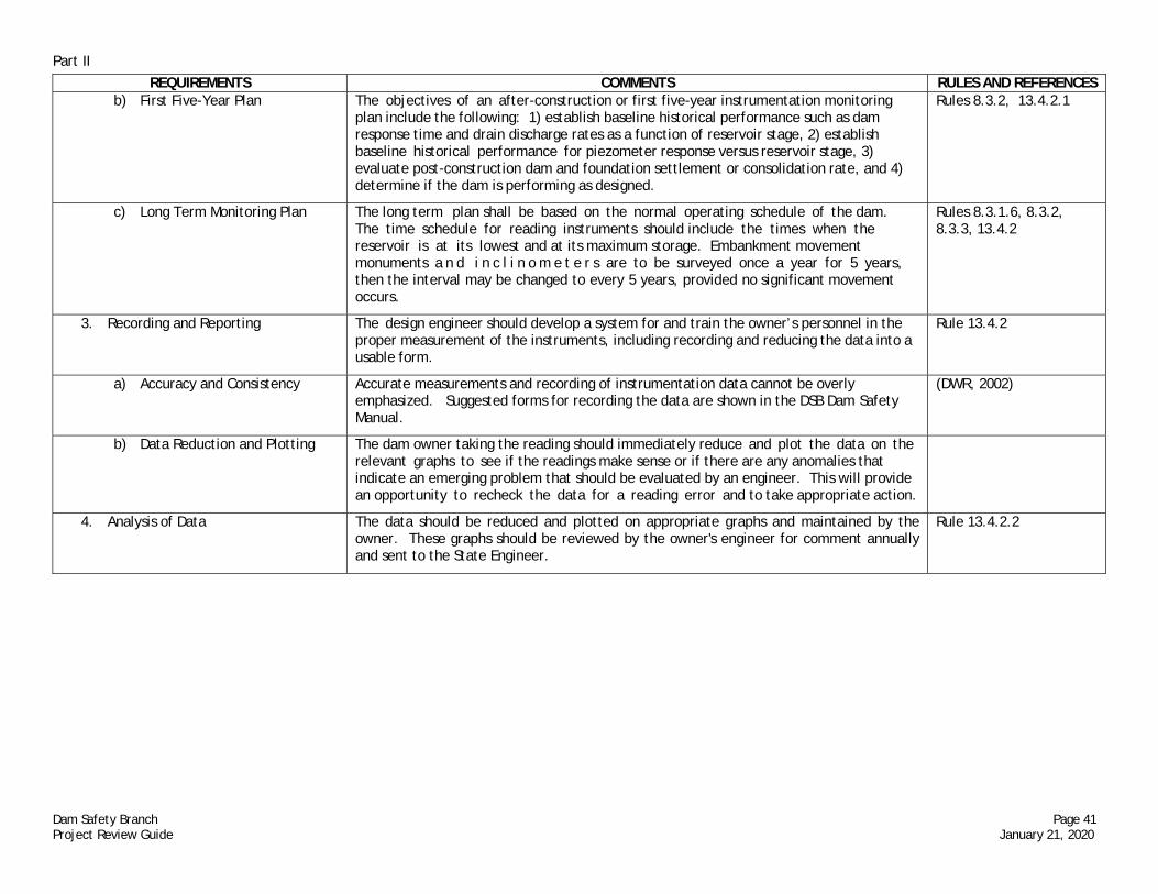
Part II
Dam Safety Branch Page 41 Project Review Guide January 21, 2020
REQUIREMENTS COMMENTS RULES AND REFERENCES b) First Five-Year Plan The objectives of an after-construction or first five-year instrumentation monitoring
plan include the following: 1) establish baseline historical performance such as dam response time and drain discharge rates as a function of reservoir stage, 2) establish baseline historical performance for piezometer response versus reservoir stage, 3) evaluate post-construction dam and foundation settlement or consolidation rate, and 4) determine if the dam is performing as designed.
Rules 8.3.2, 13.4.2.1
c) Long Term Monitoring Plan The long term plan shall be based on the normal operating schedule of the dam. The time schedule for reading instruments should include the times when the reservoir is at its lowest and at its maximum storage. Embankment movement monuments a n d i n c l i n o m e t e r s are to be surveyed once a year for 5 years, then the interval may be changed to every 5 years, provided no significant movement occurs.
Rules 8.3.1.6, 8.3.2, 8.3.3, 13.4.2
3. Recording and Reporting The design engineer should develop a system for and train the owner’s personnel in the proper measurement of the instruments, including recording and reducing the data into a usable form.
Rule 13.4.2
a) Accuracy and Consistency Accurate measurements and recording of instrumentation data cannot be overly emphasized. Suggested forms for recording the data are shown in the DSB Dam Safety Manual.
(DWR, 2002)
b) Data Reduction and Plotting The dam owner taking the reading should immediately reduce and plot the data on the relevant graphs to see if the readings make sense or if there are any anomalies that indicate an emerging problem that should be evaluated by an engineer. This will provide an opportunity to recheck the data for a reading error and to take appropriate action.
4. Analysis of Data The data should be reduced and plotted on appropriate graphs and maintained by the owner. These graphs should be reviewed by the owner's engineer for comment annually and sent to the State Engineer.
Rule 13.4.2.2

Part II
Dam Safety Branch Page 42 Project Review Guide January 21, 2020
5. Early Warning Systems
An Early Warning System (EWS) and an Early Warning System Program (EWSP) are risk reduction measures for High- and Significant-Hazard dams to provide advanced warning of an impending hydrologic event that could lead to a dam failure. EWS’s will be used to reduce the potential consequences of dangerous reservoir releases from large spillway flows and/or dam breach flows to the downstream population at risk (PAR).
EWS’s and EWSP’s are not required on dams in Colorado but may be used at candidate dams as a means to reduce the hydrologic hazard category and thereby reduce spillway design and construction requirements.
An effective EWS Program (EWSP) is a well-coordinated effort between the dam owner, dam owner’s engineer, local and state emergency management, National Weather Service (NWS), and a representative of the Colorado Dam Safety Branch. Other EWS stakeholders may be included as appropriate based on the dam location and downstream impacts. The EWSP must include consideration of effective means and methods to detect, verify, alert, and take action on extreme hydrologic events.
Dam owners contemplating development of an EWSP to reduce the risk at their dam are required to perform an EWS feasibility study. The EWS feasibility study should be prepared to assess roles and responsibilities of all identified stakeholders, EWS site constraints and costs. The EWS feasibility study should include estimated equipment capital costs, annual maintenance and training costs, and costs for any third-party contractors.
The EWSP must establish and document equipment needs and communication protocols for the necessary emergency event detection, verification, alerting and response actions during an EWS detected event. The following are key components of an effective EWSP and EWS feasibility study:
Minimum physical equipment for event detection should include a reservoir level instrument (e.g., air bubbler system) with telemetry and remote data acquisition capabilities (e.g., uplink data in a timely manner to warning entities such as NWS and emergency managers). Redundancy for equipment should be considered.
The plan must define requirements for regular maintenance, monitoring and testing of all installed equipment.
The EWS Program feasibility study should include adequate discussion of reliable means of verifying detected events.
Rules 7.2.2., 11.2, 11.3, 11.4, 11.5, 13.7 (Reclamation, 2015a)

Part II
Dam Safety Branch Page 43 Project Review Guide January 21, 2020
REQUIREMENTS COMMENTS RULES AND REFERENCES To provide for event verification and redundancy, additional equipment such as
stream gauges (e.g., flumes and weirs), instrumented seepage weirs, rainfall gauges, and/or piezometers may be incorporated into the EWS based on owner discretion and stakeholder needs.
Communication (alerting) and response (actions) protocols must be established and described in the dams Emergency Action Plan (EAP). The EAP shall be prepared in general accordance with Rule 13.7.1.
The EAP should include three inundation maps: (1) A modeled sunny day dam breach map, (2) a modeled event with the spillway operating at maximum capacity (no overtopping) and (3) a reservoir release from an overtopping dam failure.
The methods of alerting (i.e., TV, radio, social media) and responsibilities for developing messaging and delivering alerts should be discussed with stakeholders and clearly described in the EAP.
To ensure continued EWSP reliability, the EAP must be tested through annual EAP exercises. The EWSP should be reviewed annually by all key stakeholders as part of EAP exercises.
Review and approval of the EWSP by all stakeholders is required prior to acceptance of any such project by the State Engineer. Proper maintenance, operation, and exercising will be reviewed during annual physical inspection of the dam to confirm the EWSP continues to meet these minimum requirements.

Part III
Dam Safety Branch Page 44 Project Review Guide January 21, 2020
PART III - CONSTRUCTION OF JURISDICTIONAL DAMS
REQUIREMENTS COMMENTS RULES AND REFERENCES III-A. Construction Engineering Rule 8
1. Purpose Ensure construction of a safe and functional dam according to the design engineer’s approved criteria, modified as necessary to reflect unanticipated conditions that were not identified during the original site investigation. The Project Engineer is responsible for ensuring and documenting that construction proceeds in accordance with the intent of the approved plans and specifications. The Project Engineer must be a professionally registered engineer experienced in dam design and construction. As indicated below, the role of the Project Engineer depends on the Hazard Classification of the dam.
a) Construction Observation Plan (COP)
The COP must be submitted to the Colorado Dam Safety Branch (DSB) no less than 30 days prior to construction. Approval (or conditions for approval) of the COP will be issued within 10 working days of the DSB’s receipt of the plan.
Rule 8.1.2
b) Pre-construction meeting It is the Project Engineer’s responsibility to schedule a pre-construction meeting. The meeting must be held after submittal of the COP and at least 2 weeks prior to commencement of the construction. The meeting will review the respective roles of the DSB, the owner’s project engineer, and the contractor during construction to ensure that the responsibilities and authority relationships are clearly established. A tentative list of “milestone” items the State Engineer will want to observe during construction will be provided, including a list of state personnel to contact concerning any matters of construction.
The proposed plans for stream diversion and control of the river during construction will be reviewed at this meeting.
Rule 8.1.3
c) Project Engineer’s Observation The Project Engineer provides the authoritative presence on site to interpret the plans and specifications for the contractor. It is the engineer's responsibility to observe the progress and quality of the construction to determine whether the construction is proceeding in accordance with the approved plans and specifications.
Rule 8.1.3
d) Construction Records The Project Engineer maintains a record of the construction, including progress reports, test results, photographs, etc.
Rule 8.2.2
e) Progress Reports Progress reports shall be submitted at least every 30 days, or more frequently as directed by the State Engineer. Progress reports submitted via email may be acceptable as approved.
Rule 8.2.3
f) Construction Inspection Notice Generally, at least 5 day notice must be provided for scheduling DSB observation of the critical “milestone” items identified in the pre-construction meeting.
Rule 8.2.4

Part III
Dam Safety Branch Page 45 Project Review Guide January 21, 2020
REQUIREMENTS COMMENTS RULES AND REFERENCES g) Design Change Orders The Project Engineer is responsible for identifying unforeseen site conditions encountered
during construction that require deviation from the approved plans and specifications. Construction changes must be approved in writing by the State Engineer prior to implementing the change. Proposed changes during construction must be discussed with the DSB to determine if they are major changes or minor changes under the Rules. Approval of change orders can often be expedited through electronic communications.
Rule 8.2.5
h) Final Construction Inspection Advise the DSB at least 10 days prior to the project’s final inspection. Rule 8.2.6
i) Construction Completion Construction will not be considered complete until the State Engineer issues a written statement of acceptance.
Rules 8.3
III-B. Acceptance of Construction Construction will not be considered complete until the State Engineer issues a written statement of acceptance.
Rule 8.3
1. Construction Completion Documents Construction completion documents shall be submitted within 60 days following the final construction inspection.
Rule 8.3.1
a) Notification of Project Completion
The Project Engineer shall provide written notification certifying that the project was completed in general accordance with the approved plans and specifications, including approved design change orders.
Rule 8.3.1.1
b) First Fill Schedule The Project Engineer shall provide a schedule for the first filling of the reservoir specifying fill rates, water level elevations to be held for observation, and a schedule for inspecting and monitoring the dam.
Rule 8.3.1.2
c) As-constructed drawings As-constructed record drawings shall be on good-quality reproducible mylar or equivalent material and shall indicate the final conditions of the constructed project. As-constructed drawings must be stamped in accordance with the requirements of the Colorado PE licensing regulations.
Rule 8.3.1.3
d) Final Construction Report A Final Construction Report must be submitted at the end of construction. The Final Construction Report must include the following minimum information:
Summary of the periodic progress reports Discussion of problems that arose during the construction and how they were
resolved Description of foundation conditions encountered during construction Description of borrow areas and borrow materials used in construction Discussion of all construction procedures and equipment employed Summary of all construction testing methods and results Discussion of weather conditions and weather-impacted construction delays Representative photos depicting the entire construction sequence
Rule 8.3.1.4
2. Record of Monuments and Instrumentation
As appropriate, based on dam hazard classification Rule 8.3.1.5

Part III
Dam Safety Branch Page 46 Project Review Guide January 21, 2020
REQUIREMENTS COMMENTS RULES AND REFERENCES 3. First Fill and Monitoring Plan As appropriate, based on dam hazard classification Rule 8.3.1.2
4. Long-term Instrumentation Monitoring Plan
As appropriate, based on dam hazard classification Rule 8.3.1.6
5. 5-year Monitoring Plan As appropriate, based on dam hazard classification Rule 8.3.2
6. Temporary Storage Storage of water is not permitted until the State Engineer has accepted the completed construction in writing. The dam owner may request permission to temporarily store water in the completed project prior to the engineer’s submittal of the final project completion documents. Full storage will not be granted until the requirements of Rule 8 and Rule 13.7 are completely fulfilled.
Rule 8.3.3
7. Emergency Action Plan EAP templates and guidelines are available from the DSB. Rules 8.3.1, 8.3.3, 13.7
8. Construction Cost Information Final payment information for the completed project. Payment information should be itemized for all project components, and engineering costs should be itemized for design and construction services. The DSB is developing a dam construction cost database, and the final cost information will be utilized anonymously in that database. The database, when fully developed, will be used as a resource for engineers, contractors, and dam owners statewide.

Dam Safety Branch Page 47 Project Review Guide January 21, 2020
APPENDIX A - Suggested Pre-Design Meeting Agenda The following items are provided as a general guide for preparing a pre-design meeting agenda. The Pre-Design Meeting is required in accordance with Rule 6.2. The list is not intended to be all-inclusive and every item listed is not necessarily pertinent to every project.
1. Introductions 2. Project Communications:
o Roles and Responsibilities o Communication Protocols
3. Overview of SEO regulatory and design review processes: o Statutory responsibilities o Stages of design review o Role of Stakeholders
4. Project Overview: o Pertinent dam information o Risk-driving Potential Failure Modes (PFMs) o Primary dam safety concerns being addressed by the project o Primary objectives of the project o Agreed upon project scope
5. Overview of the ‘Workshop Based’ Review Process: o Typically at 30/60/90 (depending on project size) o Updates to Plans/Specs/Report at least 2 weeks in advance of workshop(s) o Working Meeting Concept o Meeting Notes o Formal Comments o Response to Comments o Formal Submittal – Typically at 60% - Should include all items listed in Rule 6.3.2 o Engineer’s Affidavit in accordance with Rule 6.5.
6. Design Criteria (use only the areas that apply to the agreed upon project scope): o Hydrology
Current hydrology (if available) Proposed hydrology updates Atmospheric Moisture Factor
o Hydraulics Outlet
Intake structure and considerations Water control equipment (e.g., gates and valves) considerations Operator type and configuration Air vent Trash racks Conduit pipe material and configuration Drawdown sizing requirement
Spillway Sizing requirements Anticipated type and configuration Erosion/scour considerations
o Geological Site Characterization o Subsurface Geotechnical Investigations
Existing investigations and laboratory results Need for additional geotechnical investigations?
o Geotechnical Embankment material classification Foundation material classification

Dam Safety Branch Page 48 Project Review Guide January 21, 2020
Slope stability evaluation requirements Settlement and Consolidation requirements Seepage and Internal Drainage Design Freeboard Design Fill material and backfill requirements:
Borrow material and testing Material Placement and Compaction Moisture conditioning Quantity estimates
Upstream slope protection requirements o Seismic Hazard Assessment o Structural
Identified critical structures Load cases Factors of safety
o Instrumentation and Monitoring Requirements o Electrical and Mechanical (dam safety related)
7. Permits: o Environmental o County o Other as applicable
8. Schedule: o Design o Construction
9. Construction Considerations: o Site Constraints o Reservoir water level during construction o Staging and storage o Concrete and import material source(s) o Diversion and Control of Water o Dewatering o Sequencing of construction activities (dam safety related) o Cold/Hot weather work
10. Other Project Considerations Based on Project Size and Complexities: o Concrete Dam Design Requirements o Communication with the Public o Consideration of a Board of Consultants o Early contractor involvement

Dam Safety Branch Page 49 Project Review Guide January 21, 2020
APPENDIX B - Plans and Specifications Checklist
The following checklists are provided as a general guide for preparing a design package for submittal to the DSB. The list is not intended to be all-inclusive, and every item listed is not necessarily pertinent to every project.
I. Plans Check List – note, the Colorado Dam Safety Branch (DSB) follows the convention of depicting water flowing
from left to right and from top to bottom of the drawing sheet. Drawings submitted for review by the DSB should follow this convention as much as reasonably possible.
A. Plan Identification
____ 1. Title Block on each sheet of plans ____ 2. Approval statements placed in lower right hand quadrant of drawing cover sheet.
Includes PE number and engineer signature, "As Constructed" statement, and the State Engineer's signature block per Rule 6.6.1.4
____ 3. A consecutive drawing numbering system beginning with "Sheet 1 of " on the first (cover) sheet
____ 4. Space for State Engineer's Construction File Number (1/2" X 3") in lower right-hand corner on each sheet
____ 5. The signature block for the responsible engineer shall state: “These plans have been prepared by me or under my direct supervision.” A PE stamp alone is not sufficient.
B. Location and Vicinity Maps Showing:
____ 1. Bar Scale and North Arrow ____ 2. Project location ____ 3. Public land grid (PLSS) ____ 4. Drainage area and topography ____ 5. Streams and gaging stations ____ 6. Roads, utilities
C. Plan(s) of Reservoir Area Showing:
____ 1. Bar Scale and North Arrow ____ 2. Topography with M.S.L. elevations with vertical datum ____ 3. Clearing areas and limits of disturbance ____ 4. Material borrow areas ____ 5. Riprap borrow areas ____ 6. Waste areas ____ 7. Equipment and Material staging and processing areas ____ 8. Centerline of dam showing bearing and coordinates of survey control points ____ 9. Public land grid ____ 10. Geotechnical Investigation drill hole and test pit locations with summary logs with
material labels and USCS classifications ____ 11. Cultural features ____ 12. Roads, utilities, streams, etc ____ 13. NWL and dead storage traverses ____ 14. Land ownership and boundaries ____ 15. Spillway location(s) ____ 16. Excavation Plan ____ 17. Reservoir area and capacity curve and table in acres and acre feet for each foot of
elevation to the design crest of the dam

Dam Safety Branch Page 50 Project Review Guide January 21, 2020
D. Dam and Spillway Plan(s)
____ 1. Scale and north arrow ____ 2. Spillway alignment and centerline stationing ____ 3. Topography with M.S.L. elevations and vertical datum ____ 4. Dam centerline stationing and coordinates of survey control points ____ 5. Section corner tie and bearings ____ 6. Structure locations ____ 7. Riprap placement limit
____ 8. Geotechnical Investigation drill hole and test pit locations with summary logs with
material labels and USCS classifications ____ 9. Locations and limits of blanket drain, toe drain(s) and other filters and drains ____ 10. Locations of instrumentation with details ____ 11. Locations of cross-sections with details
E. Outlet, Maximum, and Typical Cross-Sections of Dam
____ 1. Dam crest width, elevation, slope, and camber ____ 2. High water elevation ____ 3. Normal water elevation ____ 4. Embankment zones ____ 5. Cutoff trench depth and width ____ 6. Grout curtain or other foundation treatment
____ 7. Outlet conduit intake elevation
____ 8. Outlet conduit discharge end elevation ____ 9. Outlet conduit materials ____ 10. Outlet conduit slope, length, diameter, and stationing ____ 11. Location of seepage diaphragm and sand collar ____ 12. Toe drain, drainage blanket, & chimney drain ____ 13. Upstream slope ____ 14. Riprap thickness ____ 15. Bedding thickness ____ 16. Downstream slope ____ 17. Additional necessary sections and details
F. Longitudinal Section (Profile) Through Dam
____ 1. Crest elevation ____ 2. Geotechnical Investigation drill holes and test pit locations ____ 3. Soils logs on profile with material labels and USCS classifications ____ 4. Cutoff trench ____ 5. Grout curtain or other foundation treatment
____ 6. Dam centerline stationing ____ 7. Dam crest camber
G. Outlet Conduit Details
____ 1. Conduit Diameter ____ 2. Discharge Capacity Curve with equation(s) ____ 3. Conduit Profile with conduit length, slope, elevations, and stationing ____ 4. Air vents or cavitation protection

Dam Safety Branch Page 51 Project Review Guide January 21, 2020
____ 5. Materials ____ 6. Gage or class ____ 7. Bedding or encasement details ____ 8. Trenching and structural backfill
H. Outlet Intake and Gate Lift Structure Details
____ 1. Materials ____ 2. Gate lift or wheel ____ 3. Trashrack ____ 4. Gate stem and housing ____ 5. Gate stem support ____ 6. Gate type and head rating ____ 7. Stem protection from ice ____ 8. Gate lift mechanism ____ 9. Gate Lift Structure lock ____ 10. Gate stem encasement and details ____ 11. Outlet air vent
I. Outlet Discharge Structure & Channel Details
____ 1. Structure type ____ 2. Construction material(s) ____ 3. Stilling basin, energy dissipater, and downstream channel ____ 4. Erosion protection
J. Spillway Details
____ 1. Size and type ____ 2. Total freeboard ____ 3. Crest or Sill details
____ 4. Residual freeboard ____ 5. Material ____ 6. Channel profile, including approach and discharge sections ____ 7. Channel cross-sections, including approach and discharge areas ____ 8. Riprap or other erosion protection limits and details ____ 9. Concrete construction limits and details, including reinforcement ____ 10. Debris barrier or trashrack details ____ 11. Stilling basin details ____ 12. Discharge capacity table or curve with equation
K. Other
____ 1. Instrumentation locations and completion details ____ 2. Reservoir gage details ____ 3. Logs of drill holes and test pits with material labels and USCS classifications
____ 4. Cofferdam or diversion facilities details
____ 5. Special construction details (sequence, staging, etc.)

Dam Safety Branch Page 52 Project Review Guide January 21, 2020
II. Specifications Checklist - It is recommended that one of the standardized specification formats developed by professional organizations such as the American Institute of Architects, the National Institute of Building Sciences, or the Construction Specifications Institute be used. These standardized formats are generally quite thorough and can be easily adapted to different project types to aid the designer in preparing complete, consistent, and adequately detailed specifications.
A. Front Cover
____ 1. Title or Name of Dam (identical to plans) ____ 2. DAMID and C-number
____ 3. Water Division and Water District
B. First page behind Front Cover
____ 1. Title or Name of Dam (identical to plans) ____ 2. DAMID and C-number
____ 3. Water Division and Water District ____ 4. County ____ 5. Design Engineers Seal and Signature per Rule 6.6.1.4 ____ 6. State Engineer's approval statement and space for SEO seal per Rule 6.6.1.4 ____ 7. Per Rule 6.7.3, the signature block for the responsible engineer shall state: “These
specifications have been prepared by me or under my direct supervision.” A PE stamp alone is not sufficient.
C. Other
____ 1. Index (or Table of Contents) is complete and usable
____ 2. The specifications include the following under General Conditions. (It is r ecommended to include a separate section or chapter of the specifications for the State Engineer requirements listed below.)
____ a. Statement that the plans and specifications cannot be significantly changed without the prior written approval of the State Engineer (Rule 6.7.6)
____ b. Provision that construction shall not be considered complete until the State Engineer has accepted the construction in writing (Rule 6.7.6.2)
____ c. Statement that the owner's engineer will monitor the quality of construction (Rule 6.7.6.3)
____ 3. The key contractor submittals are listed with requirements for their submission. ____ 4. The procedures for design change orders are clearly stated. ____ 5. All materials are specified, including reference to:
____ a. Quality and type of materials ____ b. Installation/Workmanship ____ c. Applicable industry standards ____ d. Action to be taken for unsatisfactory materials or workmanship ____ e. Required tests and frequency of testing ____ 6. The specifications are in agreement with the plans

Dam Safety Branch Page 53 Project Review Guide January 21, 2020
APPENDIX C - Project Review Guide References1
1. ACI (2006), Code Requirement for Environmental Engineering Concrete Structures, American Concrete Institute,
ACI Committee 350, ACI 350. 2. ACI (2016), Specifications for Structural Concrete, American Concrete Institute, ACI Committee 301, ACI 301. 3. ACI (2019), Building Code Requirements for Structural Concrete and Commentary, American Concrete Institute,
ACI Committee 318, ACI 318. 4. ASCE (2000), Guidelines for Instrumentation and Measurements for Monitoring Dam Performance, American Society
of Civil Engineers Task Committee. 5. ASCE (2009), MOP 119 - Buried Flexible Steel Pipe: Design and Structural Analysis, American Society of Civil
Engineers Task Committee. 6. (ASCE, 2012), MOP 79 – Steel Penstocks, American Society of Civil Engineers Task Committee. 7. ASCE (2013), MOP 125 – Pipelines for Water Conveyance and Drainage, American Society of Civil Engineers Task
Committee. 8. ASCE (2018), MOP 135 – Monitoring Dam Performance, American Society of Civil Engineers Task Committee. 9. ASTM (latest year), Annual Book of Standards, ASTM International, West Conshohoken, PA. 10. Brater, Earnest; King, Horace; Lindell, James; Wei, C., (Brater, et. al., 1996), Handbook of Hydraulics, 7th ed.,
McGraw-Hill, New York. 11. C.R.S. (2008), Colorado Revised Statutes, Title 37, Article 87 Reservoirs, Denver, CO. 12. Chow, Ven Te (1959), Open-Channel Hydraulics, McGraw-Hill, New York. 13. DORA (2012), Bylaws and Rules of the State Board of Licensure for Architects, Professional Engineers and
Professional Land Surveyors, Department of Regulatory Agencies, Division of Professions and Occupations, Denver. 14. DWR (2002), Dam Safety Manual, State Engineer's Office, State of Colorado, Denver. 15. DWR (2008), Hydrologic Basin Response Parameter Estimation Guidelines, Colorado Division of Water Resources,
Dam Safety Branch, Denver. 16. DWR (2020a), Rules and Regulations for Dam Safety and Dam Construction, Colorado Division of Water Resources,
Dam Safety Branch, Denver. 17. DWR (2020b), Guidelines for Hazard Classification, Colorado Division of Water Resources, Dam Safety Branch,
Denver. 18. DWR (2020c), Guidelines for Dam Breach Analysis, Colorado Division of Water Resources, Dam Safety Branch,
Denver. 19. DWR (2020d), Hydrologic Hazard Guidelines, Colorado Division of Water Resources, Dam Safety Branch, Denver. 20. DWR (2020e), Regional Extreme Precipitation Study (REPS) Guidance, Colorado Division of Water Resources, Dam
Safety Branch, Denver. 21. DWR (2020f), Subsurface Investigation Plans Requirements and Guidance, Colorado Division of Water Resources,
Dam Safety Branch, Denver. 22. England, J.F., Jr., Cohn, T.A., Faber, B.A., Stedinger, J.R., Thomas, W.O., Jr., Veilleux, A.G., Kiang, J.E., and
Mason, R.R., Jr., 2018, Guidelines for determining flood flow frequency—Bulletin 17C: U.S. Geological Survey Techniques and Methods, book 4, chap. B5, 148 p.
23. Falvey H. T. (Falvey, 1980), Air-water Flow in Hydraulic Structures, Engineering Monograph No. 41,US Bureau of Reclamation, Denver, CO.
24. Falvey, H. T. (Falvey, 2003), Hydraulic Design of Labyrinth Weirs, ASCE Press, Reston, VA. 25. FEMA (2005a), Technical Manual: Conduits Through Embankment Dams, Federal Emergency Management Agency,
FEMA 484. 26. FEMA (2005b), Earthquake Analyses and Design of Dams, Federal Emergency Management Agency, FEMA-65 27. FEMA (2010), Technical Manual: Outlet Works Energy Dissipators, Federal Emergency Management Agency, FEMA
P-679 28. FEMA (2011), Best Practices for Design and Construction: Filters for Embankment Dams, Federal Emergency
Management Agency 29. FEMA (2014), Technical Manual: Overtopping Protection for Dams, Federal Emergency Management Agency, FEMA
P-1015. 30. FERC (1991), Engineering Guidelines, Chapter 5, Geotechnical Investigations and Studies. Federal Energy
Regulatory Commission. 31. FERC (2006), Engineering Guidelines, Chapter 4, Embankment Dams, Federal Energy Regulatory Commission. 32. FERC (2011), Filters for Embankment Dams, Best Practices for Design and Construction, Federal Energy Regulatory
Commission.

Dam Safety Branch Page 54 Project Review Guide January 21, 2020
33. FERC (2015), Engineering Guidelines, Chapter 2, Federal Guidelines for Dam Safety: Selecting and Accommodating Inflow Design Floods for Dams, Federal Energy Regulatory Commission.
34. FERC (2016), Engineering Guidelines, Chapter 3, Gravity Dams, Federal Energy Regulatory Commission. 35. FERC (2017), Engineering Guidelines, Chapter 14, Dam Safety Performance Monitoring Program, Federal Energy
Regulatory Commission. 36. FERC (2018), Engineering Guidelines, Chapter 11, Arch Dams, Federal Energy Regulatory Commission. 37. Hosking, J.R.M. and Wallis, J.R. (1997), “Regional Frequency Analysis – An Approach Based on L-Moments”,
Cambridge University Press, Cambridge, UK. 38. Lux III, F.L., and Hinchcliff, D., (Lux, 1985), Design and Construction of Labyrinth Spillways, Proc. 15th
International Congress on Large Dams, Vol. 4, Q. 59, R. 15. 39. Paxson, G., Campbell Dl, and Monroe, J., (Paxson, 2011), Evolving Design Approaches and Considerations for
Labyrinth Spillways, USSD Conference. 40. PCA (2016), Design and Control of Concrete Mixtures, Sixteenth Edition, Engineering Bulletin 001, Portland Cement
Association, www.cement.org 41. Reclamation (1976), Design of Gravity Dams, U.S. Department of the Interior, Bureau of Reclamation, Denver. 42. Reclamation (1977a), Monograph No. 19 – Design Criteria for Concrete Arch and Gravity Dams, U.S. Department of
the Interior, Bureau of Reclamation, Denver. 43. Reclamation (1977b), Design of Arch Dams, U.S. Department of the Interior, Bureau of Reclamation, Denver. 44. Reclamation (1980), Monograph No. 41 – Air-Water Flow In Hydraulic Structures, U.S. Department of the Interior,
Bureau of Reclamation, Denver. 45. Reclamation (1984), Monograph No. 25 – Hydraulic Design of Stilling Basins and Energy Dissipators, U.S.
Department of the Interior, Bureau of Reclamation, Denver. 46. Reclamation (1987a), Design of Small Dams, third edition, U.S. Department of the Interior, Bureau of Reclamation,
Denver. 47. Reclamation (1987b), Guidelines for Using Fuse Plug Embankments in Auxiliary Spillways, ACER TM No. 10, U.S.
Department of the Interior, Bureau of Reclamation, Denver. 48. Reclamation (1990), Monograph No. 42 – Cavitation in Chutes and Spillways, U.S. Department of the Interior,
Bureau of Reclamation, Denver. 49. Reclamation (2001), Water Measurement Manual, U.S. Department of the Interior, Bureau of Reclamation, revised
reprint, Denver. 50. Reclamation (2011a), Design Standard No. 13: Embankment Dams, Chapter 4 – Static Stability Analysis, U.S.
Department of the Interior, Bureau of Reclamation, Denver. 51. Reclamation (2011b), Design Standard No. 13: Embankment Dams, Chapter 5 – Protective Filters, U.S. Department
of the Interior, Bureau of Reclamation, Denver. 52. Reclamation (2011c), Design Standard No. 13: Embankment Dams, Chapter 9 – Static Deformation Analysis, U.S.
Department of the Interior, Bureau of Reclamation, Denver. 53. Reclamation (2012a), Design Standard No. 13: Embankment Dams, Chapter 2 – Embankment Design, U.S.
Department of the Interior, Bureau of Reclamation, Denver. 54. Reclamation (2012b), Design Standard No. 13: Embankment Dams, Chapter 3 – Foundation Surface Treatment,
U.S. Department of the Interior, Bureau of Reclamation, Denver. 55. Reclamation (2012c), Design Standard No. 13: Embankment Dams, Chapter 6 – Freeboard, U.S. Department of the
Interior, Bureau of Reclamation, Denver. 56. Reclamation (2012d), Design Standard No. 13: Embankment Dams, Chapter 10 – Embankment Construction, U.S.
Department of the Interior, Bureau of Reclamation, Denver. 57. Reclamation (2012e), Design Standard No. 13: Embankment Dams, Chapter 12 – Foundation and Earth Materials
Investigation, U.S. Department of the Interior, Bureau of Reclamation, Denver. 58. Reclamation (2013), Design Standard No. 13: Embankment Dams, Chapter 17 – Soil-Cement Slope Protection, U.S.
Department of the Interior, Bureau of Reclamation, Denver. 59. Reclamation (2014a), Design Standard No. 13: Embankment Dams, Chapter 7 – Riprap Slope Protection, U.S.
Department of the Interior, Bureau of Reclamation, Denver. 60. Reclamation (2014b), Design Standard No. 13: Embankment Dams, Chapter 8 – Seepage, U.S. Department of the
Interior, Bureau of Reclamation, Denver. 61. Reclamation (2014c), Design Standard No. 13: Embankment Dams, Chapter 11 – Instrumentation and Monitoring,
U.S. Department of the Interior, Bureau of Reclamation, Denver. 62. Reclamation (2014d), Design Standard No. 13: Embankment Dams, Chapter 15 – Foundation Grouting, U.S.
Department of the Interior, Bureau of Reclamation, Denver. 63. Reclamation (2014e), Design Standard No. 13: Embankment Dams, Chapter 16 – Cutoff Walls, U.S. Department of
the Interior, Bureau of Reclamation, Denver.

Dam Safety Branch Page 55 Project Review Guide January 21, 2020
64. Reclamation (2014f), Design Standard No. 13: Embankment Dams, Chapter 19 – Geotextiles, U.S. Department of the Interior, Bureau of Reclamation, Denver.
65. Reclamation (2014g), Design Standard No. 13: Embankment Dams, Chapter 21 – Water Removal and Control: Dewatering and Unwatering Systems, U.S. Department of the Interior, Bureau of Reclamation, Denver.
66. Reclamation (2014h), Design Standard No. 14: Appurtenant Structures for Dams (Spillway and Outlet Works), Chapter 1: Introduction, U.S. Department of the Interior, Bureau of Reclamation, Denver.
67. Reclamation (2014i), Design Standard No. 14: Appurtenant Structures for Dams (Spillway and Outlet Works), Chapter 3: General Spillway Design Considerations, U.S. Department of the Interior, Bureau of Reclamation, Denver
68. Reclamation (2015a), Design Standard No. 13: Embankment Dams, Chapter 13 – Seismic Analysis and Design, U.S. Department of the Interior, Bureau of Reclamation, Denver, CO.
69. Reclamation (2015b), RCEM – Reclamation Consequence Estimating Methodology, U.S. Department of the Interior, Bureau of Reclamation, Interim, Denver.
70. Reclamation (2015c), Best Practices in Dam and Levee Safety Risk Analysis, U.s Department of the Interior, Bureau of Reclamation, Denver, CO.
71. Reclamation (2016), Design Standard No. 6: Hydraulic and Mechanical Equipment, Chapter 12 – Trashracks and Trashrack Cleaning Devices, U.S. Department of the Interior, Bureau of Reclamation, Denver
72. Reclamation (2017a), Air Vent Analyses for Penstocks and Low-Level Outlets, U.S. Department of the Interior, Bureau of Reclamation, Denver.
73. Reclamation (2017b), Roller-Compacted Concrete, Design and Construction Considerations for Hydraulic Structures, Second Edition, U.S. Department of the Interior, Bureau of Reclamation, Denver
74. Reclamation (2018a), Design Standard No. 13: Embankment Dams, Chapter 19 – Geomembranes, U.S. Department of the Interior, Bureau of Reclamation, Denver.
75. Reclamation (2018b), Design Standard No. 6: Hydraulic and Mechanical Equipment, Chapter 6: Bulkhead Gates and Stoplogs, U.S. Department of the Interior, Bureau of Reclamation, Denver.
76. Tullis, J.P. (Tullis, 1989), Hydraulics of Pipelines – Pumps, Valves, Cavitation, Transients, Wiley-Interscience Publications.
77. Tullis, B., and Larchar, J., (Tullis, 2011), Determining Air Demand for Small- to Medium-Sized Embankment Dam Low-Level Outlet Works, J. Irrig. Drain Eng., 137(12), 793–800.
78. Tullis, J.P., Amanian, N., Waldron, D., (Tullis, 1995), Design of Labyrinth Spillways, Journal of Hydraulic Engineering, Vol. 121, No. 3.
79. USACE (1964), Air demand, regulated outlet works, Hydraulic Design Criteria, Sheet 050-1, U.S. Army Corp of Engineers, Washington D.C.
80. USACE (1980), Hydraulic Design of Reservoir Outlet Works, EM 1110-2-1602, U.S. Army Corp of Engineers, Washington D.C.
81. USACE (1989), Hydraulic Design of Spillways, EM 1110-2-1603, U.S. Army Corp of Engineers, Washington D.C. 82. USACE (1993), River Hydraulics, EM 1110-2-1416, U.S. Army Corps of Engineers, Washington, D.C. 83. USACE (1994a), Arch Dam Design, EM 1110-2-2201, U.S. Army Corps of Engineers, Washington D.C. 84. USACE (1994b), Flood-Runoff Analysis, EM 1110-2-1417, U.S. Army Corps of Engineers, Washington D.C. 85. USACE (1995), Gravity Dam Design, EM 1110-2-2200, U.S. Army Corps of Engineers, Washington D.C. 86. USACE (2000), Roller-Compacted Concrete, EM 1110-2-2006, U.S. Army Corps of Engineers, Washington D.C. 87. USACE (2003), Structural Design and Evaluation of Outlet Works, EM 1110-2-2400, U.S. Army Corps of Engineers,
Washington D.C. 88. USACE (2005), Stability Analysis of Concrete Structures, EM 1110-2-2100, U.S. Army Corps of Engineers,
Washington D.C. 89. USACE (2007), Earthquake Design and Evaluation of Concrete Hydraulic Structures, EM 1110-2-6053, U.S. Army
Corps of Engineers, Washington D.C 90. USACE (2009), HEC-DSSVue HEC Data Storage System Visual Utility Engine, U.S. Army Corps of Engineers, Institute
for Water Resources, Hydrologic Engineering Center, Davis. 91. USACE (2016), HEC-RAS River Analysis System Hydraulic Reference Manual Version 5.0, U.S. Army Corps of
Engineers, Institute for Water Resources, Hydrologic Engineering Center, Davis. 92. USACE (2016), Earthquake Design and Evaluation of Civil Works Projects, ER 1110-2-1806, U.S. Army Corps of
Engineers, Washington D.C. 93. USACE (2016), Strength Design for Reinforced Concrete Hydraulic Structures, EM 1110-2-2104, U.S. Army Corps of
Engineers, Washington D.C. 94. USACE (2018), Hydrologic Modeling System HEC-HMS,U.S. Army Corps of Engineers, Institute for Water Resources,
Hydrologic Engineering Center, Davis. 95. USGS (2018), Guidelines for Determining Flood Flow Frequency Bulletin 17C, Book 4, Hydrologic Analysis and
Interpretation, United States Geologic Survey, Reston Virginia.
Dam Safety Branch Page 56 Project Review Guide January 21, 2020
96. USSD (2002), Improving Reliability of Spillway Gates, United States Society of Dams, Denver, CO. 97. USSD (2006), Erosion of Unlined Spillways, United States Society of Dams, Denver, CO. 98. USSD (2016), Improving Reliability of Commonly Used Hydraulic Valves, United States Society of Dams, Denver,
CO. 99. Wallis, J.R., M.G. Schaefer, B.L. Barker and G.H. Taylor, “Regional precipitation-frequency analysis and spatial
mapping for 24-hour and 2-hour durations for Washington State”, Hydrol. Earth Syst. Sci. 11(1), 415-442, 2007.
Additional References2 1. Arcement, George J., Jr., and Schneider, Verne R. (1987), Roughness Coefficients for Densely Vegetated
Floodplains, USGS Water-Resources Investigation Report 83-4247. 2. Arcement, George J., Jr. and Schneider, Verne R., (Arcement 1989), Guide for Selecting Manning’s Roughness
Coefficients for Natural Channels and Floodplains, USGS Water-Supply Paper 2339. 3. AWWA (latest year), AWWA Manuals of Practice, American Water Works Association, Denver, CO. 4. AWWA (latest year), AWWA/ANSI Standards, American Water Works Association, Denver, CO. 5. Barnes, Harry H., Jr. (1977), Roughness Characteristics of Natural Channels, U.S. Geological Survey Water-Supply
Paper 1849, U.S. Department of the Interior, Washington, D.C. 6. Cedergren, Harry R. (1989), Seepage, Drainage, and Flow Nets, John Wiley and Sons, 3rd ed., New York. 7. Compton, R.R. (1962), Manual of Field Geology, John Wiley & Sons, Inc., New York. 8. Cudworth, A.G., Jr. (1992), Flood Hydrology Manual, U.S. Bureau of Reclamation, Denver, Colorado. 9. Duncan, J. Michael, and Wright, Stephen G., (Duncan 2005), Soil Strength and Slope Stability, John Wiley and
Sons, New Jersey. 10. FEMA (1987), Dam Safety: An Owner’s Guidance Manual, Federal Emergency Management Agency, FEMA 145. 11. FEMA (2004), Glossary of Terms, Federal Emergency Management Agency, FEMA 148 12. FEMA (2005), Earthquake Analyses & Dam Design, Federal Emergency Management Agency, FEMA 65. 13. FEMA (2005), Technical Manual for Dam Owners, Impacts of Animals on Earthen Dams, Federal Emergency
Management Agency, FEMA 473. 14. FEMA (2005), Technical Manual for Dam Owners, Impacts of Plants on Earthen Dams, Federal Emergency
Management Agency, FEMA 534. 15. FEMA (2007), Technical Manual: Plastic Pipe Used in Embankment Dams, Federal Emergency Management Agency,
FEMA P-676. 16. FEMA (2008), Geotextiles in Embankment Dams, Federal Emergency Management Agency, Status Report. 17. FEMA (2013), Inundation Mapping of Flood Risks Associated with Dam Incidents and Failures, Federal Emergency
Management Agency, FEMA P-946. 18. FEMA (2015), Evaluation and Monitoring of Seepage and Internal Erosion, Federal Emergency Management Agency,
FEMA P-1032. 19. Howard, A.M. (2015), Pipeline Installation 2.0, Relativity Publishing. 20. ISRM (1978), Suggested Methods for Quantitative Description of Discontinuities in Rock Masses, International
Society of Rock Mechanics. 21. Kirkham, R.M., and Rogers, W.P., (1981), Earthquake Potential in Colorado, Colorado Geological Survey Bulletin
43. 22. NRCS (1990), National Engineering Manual, Part 520 – Soil and Water Resource Development, U.S. Department of
Agriculture, Natural Resources Conservation Service. 23. NRCS (2005), Earth Dams and Reservoirs TR-60, U.S. Department of Agriculture, Natural Resources Conservation
Service. 24. Paxson, G., and Savage, B., (Paxson, 2006), Labyrinth Spillways: Comparison of Two Popular U.S.A. Design
Methods and Consideration of Non-Standard Approach Conditions and Geometries, International Junior Researcher and Engineer Workshop on Hydraulic Structures, J. Matos and H. Chanson (Eds.), Report CH61/06, Div. of Civil Eng., The University of Queensland, Brisbane, Australia.
25. Reclamation (1974), Earth Manual, 2nd ed., U.S. Department of the Interior, U.S. Bureau of Reclamation, Denver. 26. Seed, H.B., and Idriss, I.M., (1971), Simplified Procedure for Evaluating Soil Liquefaction Potential, Journal of the
Soil Mechanics and Foundations Division, ASCE, Vol. 97, No. SM9. 27. Seed, R., Cetin, K., Moss, R., Kammerer, A., Wu, J., Pestana, J., Reiner, M., Sancio, R., Bray, J., Kayen, R., and
Farig, A., (Seed, et. al., 2003), Recent Advances in Soil Liquefaction Engineering; A Unified Consistent Framework, Earthquake Engineering Research Center, University of California, Berkeley, Report No. EERC 2003-06.
28. Tullis, B.P. and Larchar, J. (2011), Determining Air Demand for Small- to Medium-Sized Embankment Dam Low-Level Outlet Works, Journal of Irrigation and Drainage Engineering, American Society of Civil Engineers.
29. Tweto, O. (1979), Geologic Map of Colorado, U.S. Department of the Interior, U.S. Geological Survey.

Dam Safety Branch Page 57 Project Review Guide January 21, 2020
30. USACE (2009), HEC-GeoHMS Geospatial Hydrologic Modeling Extension, U.S. Army Corps of Engineers, Institute for Water Resources, Hydrologic Engineering Center, Davis.
31. USACE (2009), HEC-GeoRAS GIS Tools for Support of HEC-RAS using ArcGIS©, U.S. Army Corps of Engineers, Institute for Water Resources, Hydrologic Engineering Center, Davis.
32. USGS (2002), Interpolated Probabilistic Ground Motion for the Conterminous 48 States by Latitude Longitude, Version 5.0.9.a-10/21/2009, U.S. Department of the Interior, U.S. Geological Survey.
33. USGS (2006), Quaternary Fault and Fold Database of the United States, U.S. Department of the Interior, U.S. Geological Survey.
34. Washington (1993), Dam Safety Guidelines, Washington State Department of Ecology, Water Resources Program Dam Safety Office, Olympia, WA.
35. Warner, James, (Warner, 2004), Practical Handbook of Grouting, John Wiley and Sons, New York. 36. Weaver, K.D., and Bruce, D.A., (Weaver, 2007), Dam Foundation Grouting, ASCE Press, American Society of Civil
Engineers.
Reference Websites3 1. http://www.asce.org/ 2. http://www.astm.org/ 3. http://www.awwa.org/publications/standards 4. https://www.cement.org/ 5. http://www.colorado.gov/cs/Satellite/DORA/CBON/DORA/1251627010216 6. https://www.concrete.org/ 7. https://www.crsi.org/ 8. https://damoutletworks.org 9. http://www.damsafety.org/ 10. https://damsafety.org/resource-center 11. http://earthquake.usgs.gov/hazards/apps/ 12. http://earthquake.usgs.gov/hazards/designmaps/ 13. https://www.fema.gov/technical-manuals-and-guides 14. http://geosurveystore.state.co.us/c-13-geological-hazards.aspx 15. http://www.hec.usace.army.mil/software/ 16. http://ngmdb.usgs.gov 17. http://www.nws.noaa.gov/oh/hdsc/studies/pmp.html 18. https://www.publications.usace.army.mil/USACE-Publications/Engineer-Manuals/ 19. http://water.state.co.us/SurfaceWater/DamSafety 20. http://water.usgs.gov/osw/streamstats/colorado.html 21. http://websoilsurvey.nrcs.usda.gov/app/ 22. https://www.usbr.gov/tsc/techreferences/designstandards-datacollectionguides/designstandards.html 23. http://www.ussdams.org/ 24. Western Dam Engineering Technical Notes (available on the following website):
http://water.state.co.us/SurfaceWater/DamSafety/Pages/DamSafety.aspx) Notes:
1. References provided is this section pertain to specific requirements listed in this Project Review Guide. 2. References listed in this section pertain to special dam safety and design topics that are intended to be additional references for the users
of this document to research and use as needed. 3. Website references are intended to provide a source of recognized agencies or organizations that provide dam safety information or
technical content to support dam design, maintenance, and/or inspection. 4. Users of this guidance document should confirm that latest versions of the references are applied prior to use for a specific document. 5. The references provided in this section are not intended to be an all-inclusive list of references and the users of this document are
encouraged to search out and apply all relevant documents for design, monitoring, inspections, and emergency management activities associated with dams.