Rate of growth of wedge type intercrystalline creep micro ...
Upload
independentCategory
view
2download
0
Version of 03/31/2005. 1/23
Stark effect in a wedge-shaped quantum box.
Jorge-Alejandro Reyes-Esquedaa,∗ , Carlos I. Mendozab, Marcelo del Castillo-Mussota,
Gerardo J. Vázqueza.
aInstituto de Física, UNAM, 04510, P. O. Box 20-364, 01000, México, D. F., Mexico.
bInstituto de Investigaciones en Materiales, UNAM, P. O. Box 70-360, 04510, México, D. F., Mexico.
Abstract
The effect of an external applied electric field on the electronic ground state
energy of a quantum box with a geometry defined by a wedge is studied by carrying out a
variational calculation. This geometry could be used as an approximation for a tip of a
cantilever of an atomic force microscope. We study theoretically the Stark effect as
function of the parameters of the wedge: its diameter, angular aperture and thickness; as
well as function of the intensity of the external electric field applied along the axis of the
wedge in both directions; pushing the carrier towards the wider or the narrower parts. A
confining electronic effect, which is sharper as the wedge dimensions are smaller, is
clearly observed for the first case. Besides, the sign of the Stark shift changes when the
angular aperture is changed from small angles to angles θ>π. For the opposite field, the
electronic confinement for large diameters is very small and it is also observed that the
Stark shift is almost independent with respect to the angular aperture.
PACS: 73.21.-b; 85.85.+j; 02.90.+p.
Keywords: Variational calculation; Stark effect; Quantum dots; Atomic force microscope;
Nanocantilevers; NEMS.
∗ Corresponding author. Tel.: +52 55 5622-5184; Fax: +52 55 5616-1535. E-mail address: [email protected] (J.-A. Reyes-Esqueda)
J. A. Reyes-Esqueda, et al.

Version of 03/31/2005. 2/23
1. Introduction
In the last few years, the study of the properties of nanostructures has become
very important in looking for new technological applications. Specially, the behavior of
their electronic and optical properties in the presence of an external electric field has been
widely studied, both theoretical and experimentally [1-8]. For example, in the case of
semiconductor nanocrystals, the external field can be used to control electron transfer in
quantum dot-based single electron devices and to control elementary qubit operations in
such systems [9, 10]. Also, the electric field makes possible the mapping of the electronic
wave functions of quantum dots in scanning-tunneling-microscopy experiments [11].
Furthermore, the mechanisms of carrier transport in quantum well structures and the
capture process as function of an electric field, which may be due to a piezoelectric
effect, have attracted much interest for the design and optimization of electronic and
photonic devices [12].
On the other hand, from the standpoints of practical device application and
fundamental science, new detection techniques using micro/nanomechanical beams and
cantilevers have received increasing attention. Thus, research about the influence of
quantum effects on the piezoresistance of two-dimensional heterostructures has been
made [13]. Moreover, since cantilever based sensors have become a standard on micro-
and nano-electromechanical systems (MEMS and NEMS) for detection of magnitudes
with resolution in the pico-scale, there is recent work in developing electromechanical
models for a transducer based on a lateral resonating cantilever [14], a feedback
controlled nanocantilever device [15], and biosensors based on polymer microcantilevers
[16]. Additionally, very recently, Qi Ye, et al, have beginning a large-scale fabrication of
carbon nanotube probe tips for atomic force microscopy (AFM) imaging applications
[17] and Liwei Chen, et al. have already made imaging of gold nanoclusters and
biomolecules in ambient and fluid environments with this kind of AFM probes [18].
As said above, the study and understanding of electronic properties of systems on
the nano-scale is very important for a wide range of possible applications. One example
of this is the modeling of the tip and sample surfaces in scanning tunneling microscopy as
confocal hyperboloids [19] and the consequent construction of their normal modes and
J. A. Reyes-Esqueda, et al.

Version of 03/31/2005. 3/23
Green functions by using prolate spheroidal coordinates [20]. Another example is the
importance on electrostatic force gradient microscopy of the electrostatic forces between
sharp tips and metallic and dielectric samples given the geometry of the tip [21]. Finally,
it results that these electrostatic forces, and even Casimir force, have influence on the
mechanical properties of cantilevers very dependent on the geometry of the cantilever tip
[22]. Following this motivation and the experience obtained in the study of Stark effect
with variational techniques in several geometries [7, 8, 23], we decided to study this
effect in the tip of a typical cantilever of an atomic force microscope (AFM) using as a
first approximation the geometry given by a wedge since, as a matter of fact, there exist
commercial triangular-shaped silicon microcantilevers (Thermomicroscopes) [24].
Therefore, in the present work, as a first approximation to the AFM tip, we carry out a
variational calculation to study the influence of an external applied electric field on the
electronic ground-state energy of a wedge-shaped quantum box as function of the
parameters of the wedge (diameter, angular aperture and thickness) and the intensity and
direction of the electric field. This last is applied along the axis of the wedge in both
directions, to the wider and to the narrower parts. For our calculations we suppose that
the dielectric constant of the wedge is the same as the medium where it is embedded. In
future works, we will consider variations of the dielectric constant of the wedge as well
as other electric fields, calculations for excited states and the inclusion of impurities
inside the tip.
In section 2 we present our calculations. Then, in section 3 we discuss our results,
and finally we give our conclusions.
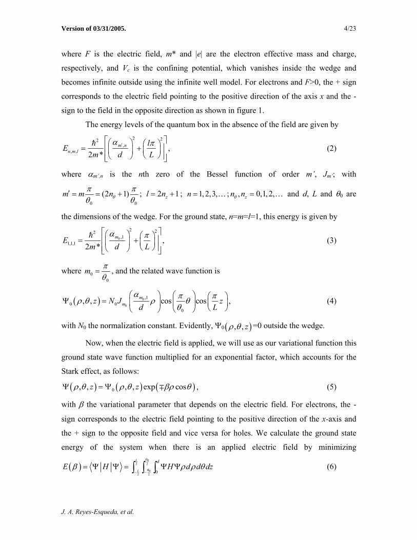
2. Calculation
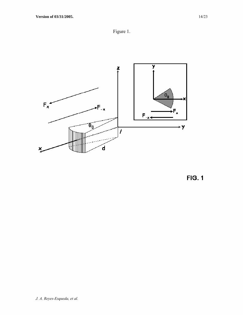
In cylindrical coordinates, the Hamiltonian of a carrier in a quantum box defined
by the geometry of a wedge with an electric field applied along its symmetry axis as
shown in figure 1, is given by
(2
cos , ,2 * cpH e F Vm
ρ θ ρ θ= ± + )z , (1)
J. A. Reyes-Esqueda, et al.
Version of 03/31/2005. 4/23
where F is the electric field, m* and |e| are the electron effective mass and charge,
respectively, and Vc is the confining potential, which vanishes inside the wedge and
becomes infinite outside using the infinite well model. For electrons and F>0, the + sign
corresponds to the electric field pointing to the positive direction of the axis x and the -
sign to the field in the opposite direction as shown in figure 1.
The energy levels of the quantum box in the absence of the field are given by 2 22
,, , ,
2 *m n
n m llE
m d Lα π′
⎡ ⎤⎛ ⎞ ⎛ ⎞= +⎢⎜ ⎟ ⎜ ⎟⎝ ⎠⎢ ⎥⎝ ⎠⎣ ⎦
⎥ (2)
where αm’,n is the nth zero of the Bessel function of order m’, Jm’; with
0 0
(2 1)m m nθπ πθ θ
′ = = + ; ; 2 1zl n= + 1, 2,3,n = … ; , 0,1, 2,zn nθ = … and d, L and θ0 are
the dimensions of the wedge. For the ground state, n=m=l=1, this energy is given by
0
2 22,1
1,1,1 ,2 *
mEm d L
α π⎡ ⎤⎛ ⎞ ⎛ ⎞⎢= +⎜ ⎟ ⎜ ⎟⎝ ⎠⎢ ⎥⎝ ⎠⎣ ⎦
⎥ (3)
where 00
m πθ
= , and the related wave function is
( ) 0
0
,10 0
0
, , cos cosmmz N J z
d Lα π πρ θ ρ θ
θ⎛ ⎞ ⎛ ⎞ ⎛Ψ = ⎜ ⎟ ⎜ ⎟ ⎜
⎝ ⎠⎝ ⎠⎝ ⎠
⎞⎟ , (4)
with N0 the normalization constant. Evidently, Ψ0 ( ), , zρ θ =0 outside the wedge.
Now, when the electric field is applied, we will use as our variational function this
ground state wave function multiplied for an exponential factor, which accounts for the
Stark effect, as follows:
( ) ( ) (0, , , , exp cosz z )ρ θ ρ θ βρΨ = Ψ ∓ θ , (5)
with β the variational parameter that depends on the electric field. For electrons, the -
sign corresponds to the electric field pointing to the positive direction of the x-axis and
the + sign to the opposite field and vice versa for holes. We calculate the ground state
energy of the system when there is an applied electric field by minimizing
( )0
2 2
02 2 0
L
L
dE H H
θ
θ d d dzβ ρ ρ θ− −
= Ψ Ψ = Ψ Ψ∫ ∫ ∫ (6)
J. A. Reyes-Esqueda, et al.
Version of 03/31/2005. 5/23
with respect to β and then, we define the Stark shift as
( ) 1,1,1E E Eβ∆ = − . (7)
3. Results and Discussion
All the results will be presented in reduced atomic units (a.u.*), which correspond
to a length unit of an effective Bohr radius, 2
2* *a m eε= , and an effective Rydberg,
42 2
** 2m eR ε= . The electric field is also given in atomic units as 20 2 *
eF aε= , with
ε=1 as it was stated above.
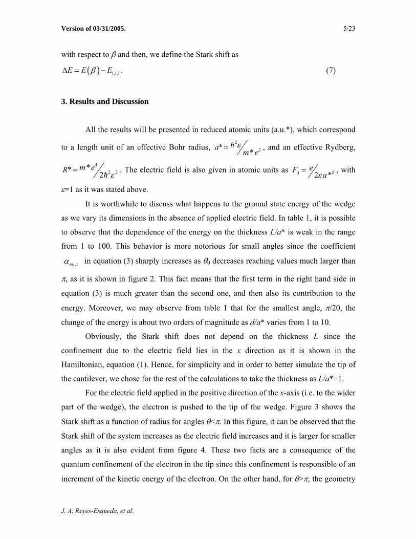
It is worthwhile to discuss what happens to the ground state energy of the wedge
as we vary its dimensions in the absence of applied electric field. In table 1, it is possible
to observe that the dependence of the energy on the thickness L/a* is weak in the range
from 1 to 100. This behavior is more notorious for small angles since the coefficient
0 ,1 m α in equation (3) sharply increases as θ0 decreases reaching values much larger than
π, as it is shown in figure 2. This fact means that the first term in the right hand side in
equation (3) is much greater than the second one, and then also its contribution to the
energy. Moreover, we may observe from table 1 that for the smallest angle, π/20, the
change of the energy is about two orders of magnitude as d/a* varies from 1 to 10.
Obviously, the Stark shift does not depend on the thickness L since the
confinement due to the electric field lies in the x direction as it is shown in the
Hamiltonian, equation (1). Hence, for simplicity and in order to better simulate the tip of
the cantilever, we chose for the rest of the calculations to take the thickness as L/a*=1.
For the electric field applied in the positive direction of the x-axis (i.e. to the wider
part of the wedge), the electron is pushed to the tip of the wedge. Figure 3 shows the
Stark shift as a function of radius for angles θ<π. In this figure, it can be observed that the
Stark shift of the system increases as the electric field increases and it is larger for smaller
angles as it is also evident from figure 4. These two facts are a consequence of the
quantum confinement of the electron in the tip since this confinement is responsible of an
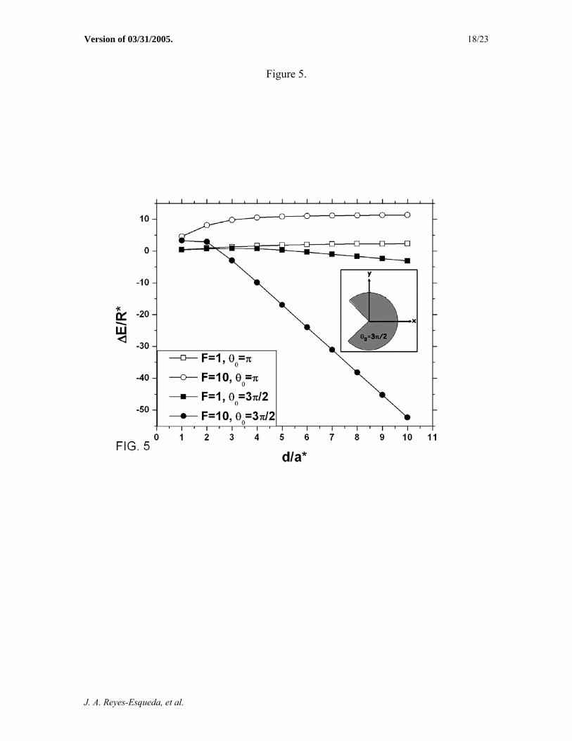
increment of the kinetic energy of the electron. On the other hand, for θ>π, the geometry
J. A. Reyes-Esqueda, et al.

Version of 03/31/2005. 6/23
of the wedge changes to a Packman-like shape rather than a tip (as shown in the inset of
figure 5 for θ0=3π/2). In this case, depending on the field, the Stark shift could be either
positive or negative as it is also shown in figure 5.
In figure 6, ∆E is shown as a function of the electric field for various wedge radii.
In the case θ0=π/20, it can be observed that for a given radius, the electric field enhances
the energy of the electron since this is more strongly confined to the tip of the wedge.
This fact is not true anymore for θ0=3π/2. Indeed, in this figure, it can be observed the
change of the sign of ∆E as the radius increases for θ0=3π/2. For d/a*=1, E(β) is still
larger than E1,1,1, but for d/a* =5 or 10 this is no longer true. The change of sign in ∆E,
for a given value of the electric field, is a direct consequence of the choice of the origin
for the electric potential, VF=|e|Fx, at x=0, as we will discuss later.
In figure 7, we plot the ground-state electronic density, Ψ2(x, y, z=0), for the
wedge-shaped geometry with no applied electric field (panel a)) and with an applied
electric field (panel b)). The effect of the field is to push the electron towards the tip of
the wedge as shown by the maximum of Ψ2, which represents the most probable position
of the electron. On the other hand, for the Packman-shaped geometry, if there is no
applied field, the situation is very similar to that of the wedge-shaped case in which Ψ2
presents a maximum located at some point x>0, as shown in figure 8 a). When we apply a
small electric field, the maximum of Ψ2 is only slightly shifted towards the origin (figure
8 b)). However, if the electric field is strong enough, then the maximum shifts to a
position with x<0 and Ψ2 shows two peaks of the same height due to the shape (figure 8
c)). This height is the same because it is equally probable to find the electron located in
any of the two sides (jaws) of the Packman-shaped geometry.
The change of sign in ∆E of figures 5 and 6 can be understood more clearly if we
consider a one-dimensional analogy of the system. First, we discuss the wedge-shaped
geometry. In absence of an electric field, the electron can be seen as a particle moving in
a one-dimensional potential with a minimum near the position of the maximum of Ψ2, as
it is shown in figure 7 c). The horizontal line represents the ground-state energy, E1,1,1, of
this system. When an electric field is applied, the resulting potential in which the particle
is moving can be approximated by the potential without electric field plus the potential of
J. A. Reyes-Esqueda, et al.

Version of 03/31/2005. 7/23
the applied electric field, VF=|e|Fx. These potentials are shown in figure 7 d). As it can be
seen in the figure, the resulting potential presents a minimum shifted towards the tip of
the wedge, in accordance with the behavior of Ψ2. It is also evident that the minimum is
shallower than in the case in which there is no applied field, and therefore, its ground-
state energy, E(β), is larger than E1,1,1, giving rise to a positive value of the Stark shift,
∆E>0. The situation is very similar for the Packman-shaped geometry. In absence of
applied field, the electron moves in a potential with a minimum located near the
maximum of the electronic density, with a ground-state energy, E1,1,1, as shown in figure
8 d). When a small electric field is applied, the resulting potential presents a shallower
minimum shifted towards the origin but always with x>0. The corresponding ground-state
energy, E(β), is larger than E1,1,1, giving again rise to a positive value of the Stark shift,
∆E>0 (figure 8 e)). However, if the field is large enough, then the potential may present a
deeper minimum shifted towards x<0, with a corresponding ground-state energy, E(β),
smaller than E1,1,1. This gives rise to a negative value of the Stark shift, ∆E<0, which is
not present in the wedge-shaped geometry (figure 8 f)). As it results clear, this change in
sign is only a consequence of choosing the origin of the electric potential at x=0, and it
could be suppressed, for a given field, with a different choice. The important fact is that,
the application of an electric field pointing to the wider part of the wedge pushes the
electron to the opposite side, confining it either to the tip of the wedge or to its two tips
for the Packman-shaped geometry.
For an electric field applied to the opposite direction (i.e. to the narrower part of
the wedge) the electron is pushed to the wider side of the wedge and then the quantum
confinement is smaller (if the field is not very strong) than in the case in which there is
not applied field. Therefore, ∆E is always negative as it is shown in figure 9. It can be
also observed that, given an angle and a radius, the magnitude of the Stark shift increases
as the electric field is increased. However, the most important result in this case is that
the Stark shift is very insensitive to the angular aperture of the wedge. For instance, when
F/F0=10, it can be observed in figure 9 that the Stark shift is almost the same for π/20,
π/15 and π/10 and also for π/2, π and 3π/2. Moreover, we found that E(β) tends to almost
zero for small fields (F/F0=0.5 and 1) as the radius is increased, while for F/F0=10 it
J. A. Reyes-Esqueda, et al.
Version of 03/31/2005. 8/23
tends to a negative value, in an almost independent way of the angular aperture in both
cases.
4. Conclusions
We have analyzed the effect of an applied electric field on the electronic ground-
state energy of a quantum box with a geometry defined by a wedge. We have shown how
the quantum confinement effect strongly depends on the geometry of the system and the
direction of the electric field. When the field is applied directed to the wider part of the
wedge, the electron is pushed to the opposite side, then being strongly confined either to
the tip of the wedge or to its two tips for the Packman-shaped geometry, increasing in
both cases its kinetic energy. However, due to the choice of the origin of the electric
potential, for a particular value of the applied electric field, the Stark shift may even be
negative. This change of sign may be avoided by changing adequately the origin of the
electric potential. Finally, for the field applied in the opposite direction (to the tip of the
wedge), there is no electronic confinement for the considered applied electric fields and,
given that the electronic energy decreases, the Stark shift is always negative and is very
insensitive to the angular aperture of the wedge. As a future work, we will consider the
influence of the dielectric constant of the wedge, to incorporate more complicated applied
electric fields, and calculate the energies of excited states as well as the inclusion of
impurities in the system, in order to make a more realistic modeling of the tip of a typical
cantilever of an atomic force microscope.
5. Acknowledgements
This work has been partially supported by grant IN-106201 (DGAPA, UNAM,
México). J. A. Reyes-Esqueda also acknowledges illuminating discussions with Lorea
Chaos Cador.
J. A. Reyes-Esqueda, et al.

Version of 03/31/2005. 9/23
6. References
1. J. A. Brum, G. Bastard. Phys. Rev. B 31 (1985) 3893.
2. G. Bastard, E. E. Mendez, L. L. Chang, L. Esaki. Phys. Rev. B 28 (1983) 3241.
3. D. A. B. Miller, D. S. Chemla, T. C. Damen, A. C. Gossard, W. Wiegmann, T. H.
Wood, C. A. Burrus. Phys. Rev. B 32 (1985) 1043.
4. Y. P. Feng, H. S. Tan, H. N. Spector. Superlattices Microstruc. 17 (1995) 267.
5. W. Sheng, J. P. Leburton. Phys. Rev. Lett. 88 (2002) 167401.
6. A. Stróżecka, W. Jaskólski, M. Zieliński, G. W. Bryant. Vacuum 74 (2004) 259.
7. G. J. Vázquez, M. Castillo-Mussot, C. I. Mendoza, H. N. Spector. Phys. Stat. Sol. (c)
1 (2004) S54. C. I. Mendoza, G. J. Vázquez, M. Castillo-Mussot, H. N. Spector. 1
(2004) S74.
8. V. A. Harotyunyan, K. S. Aramyan, H. Sh. Petrosyan, G. H. Demirjian. Physica E 24
(2004) 173.
9. P. Zhang, X-G. Zhao. J. Phys. Condensed Matter 13 (2001) 8389.
10. I. Shtrichman, C. Metzner, B. D. Gerardot, W. V. Schoenfeld, P. M. Petroff. Phys.
Rev. B 65 (2002) 081303(R).
11. O. Millo, D. Katz, Y. W. Cao, U. Banin. Phys. Rev. Lett. 86 (2001) 5751.
12. L. Villegas-Lelovsky, G. González de la Cruz. J. Appl. Phys. 95 (2004) 4204.
13. H. Yamaguchi, S. Miyashita, Y. Hirayama. Physica E 24 (2004) 70. H. Yamaguchi,
S. Miyashita, Y. Hirayama. Appl. Surface Sc. 237 (2004) 649.
14. J. Teva, G. Abadal, Z. J. Davis, J. Verd, X. Borrisé, A. Boisen, F. Pérez-Murano, N.
Barniol. Ultramicroscopy 100 (2004) 225.
15. C. Ke, H. D. Espinosa. Appl. Phys. Lett. 85 (2004) 681.
16. X. R. Zhang, X. Xu. Appl. Phys. Lett. 85 (2004) 2423.
17. Q. Ye, A. M. Cassell, H. Liu, K-J. Chao, J. Han, M. Meyyappan. Nanoletters 4 (2004)
1301.
18. L. Chen, C. L. Cheung, P. D. Ashby and C. M. Lieber. Nanoletters 4 (2004) 1725.
19. G. Seine, R. Coratger, A. Carladous, F. Ajustron, R. Pechou, J. Beauvillain. Phys.
Rev. B 60 (1999) 11045. E. Ley-Koo. Phys. Rev. B 65 (2002) 077401. G. Seine, R.
Coratger, A. Carladous, F. Ajustron, R. Pechou, J. Beauvillain. Phys. Rev. B 65
(2002) 077402.
J. A. Reyes-Esqueda, et al.

Version of 03/31/2005. 10/23
20. N. Aquino, E. Castaño, E. Ley-Koo, S. E. Ulloa. Rev. Mex. Fis. E 50 (2004) 54.
21. S. Gómez-Moñivas, L. S. Froufe-Pérez, A. J. Caamaño, J. J. Sáenz. Appl. Phys. Lett.
79 (2001) 4048. G. M. Sacha, J. J. Sáenz. Appl. Phys. Lett. 85 (2004) 2610.
22. A. A. Chumak, P. W. Milonni, G. P. Berman. Phys. Rev. B 70 (2004) 085407.
23. J. W. Brown, H. N. Spector. J. Appl. Phys. 59 (1986) 1179.
24. For instance, these cantilevers were used by F. Tian, et al. to study the potential-
induced surface stress of a solid electrode in an electrochemical cell. F. Tian, J. H.
Pei, D. L. Hedden, G. M. Brown, T. Thundat. Ultramicroscopy 100 (2004) 217.
J. A. Reyes-Esqueda, et al.
Version of 03/31/2005. 11/23
Figure Captions
Figure 1. The geometry of the wedge and the electric field applied along its symmetry
axis in two directions: to the tip and to the wider part. This last corresponds to the
positive direction of the axis x. 0≤ρ≤d; -θ0/2≤θ≤θ0/2; -l/2≤z≤l/2.
Figure 2. It is shown the first zero of the correspondent Bessel function given the angular
aperture, θ0, of the wedge.
Figure 3. The Stark shift of the electron’s energy, ∆E, is shown as a function of the
wedge radius for two electric fields, which are applied directed to the positive
direction of the axis x.
Figure 4. ∆E is shown as a function of the angular aperture θ0 for d/a*=5 and F/F0=1.
Figure 5. Similar to figure 3, but with angles θ≥π. The particular shape of the wedge in
the case of θ=3π/2 is shown in the inset.
Figure 6. ∆E is shown, for the two extreme angular apertures, as a function of the electric
field directed to the positive direction of the axis x for various wedge radii.
Figure 7. The ground-state electronic density, Ψ2(x, y, z=0), for θ0=π/20 and d/a*=10, is
shown for F/F0=0 (panel a)) and F/F0=10 (panel b)). The analogue 1D potential is
shown in panels c) and d). The Stark shift, ∆E, is positive in this case.
Figure 8. The ground-state electronic density, Ψ2(x, y, z=0), for θ0=3π/2 and d/a*=2, is
shown for F/F0=0 (panel a)), F/F0=0.5 (panel b)) and F/F0=10 (panel c)). The
analogue 1D potential is shown in panels d), e) and f). The Stark shift, ∆E, is
positive or negative depending on the magnitude of the applied electric field.
J. A. Reyes-Esqueda, et al.
Version of 03/31/2005. 12/23
Figure 9. ∆E is shown as a function of the wedge radius for various electric fields, which
are applied directed to the tip of the wedge.
J. A. Reyes-Esqueda, et al.

Version of 03/31/2005. 13/23
Table captions
Table 1. The system electronic ground state energy when there is not applied field is
shown as a function of its dimensions.
J. A. Reyes-Esqueda, et al.
Version of 03/31/2005. 14/23
Figure 1.
J. A. Reyes-Esqueda, et al.

Version of 03/31/2005. 15/23
Figure 2.
J. A. Reyes-Esqueda, et al.

Version of 03/31/2005. 16/23
Figure 3.
J. A. Reyes-Esqueda, et al.

Version of 03/31/2005. 17/23
Figure 4.
J. A. Reyes-Esqueda, et al.
Version of 03/31/2005. 18/23
Figure 5.
J. A. Reyes-Esqueda, et al.

Version of 03/31/2005. 19/23
Figure 6.
J. A. Reyes-Esqueda, et al.

Version of 03/31/2005. 20/23
Figure 7.
J. A. Reyes-Esqueda, et al.

Version of 03/31/2005. 21/23
Figure 8.
J. A. Reyes-Esqueda, et al.

Version of 03/31/2005. 22/23
Figure 9.
J. A. Reyes-Esqueda, et al.

Version of 03/31/2005. 23/23
Table 1.
d/a* L/a* E1,1,1(π/20) E1,1,1(π/10) E1,1,1(π/2) E1,1,1(π) E1,1,1(3π/2)
1 655.90 219.40 36.24 24.55 21.26 10 646.12 209.63 26.47 14.78 11.49
1 100 646.03 209.54 26.37 14.68 11.39 1 171.37 62.25 16.46 13.54 12.71 10 161.60 52.48 6.69 3.76 2.94
2 100 161.50 52.38 6.59 3.67 2.84 1 50.24 22.96 11.51 10.78 10.58 10 40.47 13.19 1.74 1.01 0.81
4 100 40.37 13.09 1.64 0.91 0.71 1 27.81 15.69 10.60 10.27 10.18 10 18.04 5.91 0.83 0.50 0.41
6 100 17.94 5.82 0.73 0.40 0.31 1 19.96 13.14 10.28 10.09 10.04 10 10.19 3.37 0.51 0.32 0.27
8 100 10.09 3.27 0.41 0.23 0.17 1 16.32 11.96 10.13 10.01 9.98 10 6.55 2.19 0.36 0.24 0.21
10 100 6.46 2.09 0.26 0.14 0.11
J. A. Reyes-Esqueda, et al.
Copyright © 2022 FDOKUMEN