High Temperature Tensile Creep of Magnesium Oxide Single Crystals
Upload
khangminh22Category
view
1download
0
Rate of growth of wedge type intercrystalline creep micro-cracks of nickel aluminide alloys
A.M. Hashem Production Eng. & Design Dept., Faculty of Engineering, Minia University, Egypt
Abstract
Under Iugh temperature creep is active. Intercrystalline creep micro-cracks takes place due to the initiation and growth of intercrystalline cavities. Polycrystalline nickel aluminide with boron alloy was investigated. This alloy was produced by powder metallurgical using Hot Isostatic Pressing (HIP). Various heat treatments were used to produce different initial grain size. The grain sizes were 20.7, 2 1 .O5, 10 1.5 and 106.0 pm. The micro- cracks has been studied after creep fracture at a temperatures of 800, 850 and 900 "C and a stress levels of 20 to 90 MPa. The creep fracture surfaces of longitudinal section of specimens which exhibited creep were examined by using an image analysis system. The growth rate, length, thickness and area of the micro-crack of the fractured specimen are determined at different stress, temperature and grain size. It was found that the micro- cracks are mainly dependent on the initial grain size. Cavities in large- grained (106.0 pm) alloy grew more slowly than those in fine-grain (20.27 pm) alloy. The crack density factor (X) is proportional to the grain size. increases with increasing grain size, and is independent to the applied stress.
1 Introduction
The intermetallic nickel aluminide Ni3Al alloys have being designed for the high temperature range 800 "C to 1300 "C. It surpasses superalloys in terms of melting temperature (1635 "C, 250 "C higher than for superalloys), density (5.9 ~ ~ / m ~ , two-thirds of superalloys), thermal conductivity (76 W/m0K, three to seven times that of superalloys), and oxidation resistance and greater creep strength[l -51.
Transactions on Engineering Sciences vol 32, © 2001 WIT Press, www.witpress.com, ISSN 1743-3533

This alloy can be processed using conventional metallurgical manufacturing techniques like melting and forging metallurgy, powder metallurgy and single -crystal casting.
One critical shortcoming of Ni3Al in structural applications is low ductility and toughness at low temperatures. However, recent work has shown that the mechanical properties of this alloy can be improve by composite reinforcement or ternary alloy additions such as boron [5,6] . Moderately tougher Ni3Al based materials have been produced by macro- alloying with additions to produce multiphase microstructures
The alloy used in this paper is nickel aluminide with boron produced by power metallurgy by HIP technique. In this method, powder is canned, evacuated and hot isostatic pressed at 1200 "C, 2000 bar and 4 hours. The HIP process offers a special advantage in that it can be used for fabrication of near-net-shape parts directly from powder [3].
The aim of this paper, is determination of the micro-crack of intercrystalline alloy after creep deformation. This can be determined in metallographic investigation a specimen which exhibited creep were examined by using an image analysis system at different levels of stress (20- 90 MPa), test temperature (800- 900 "C) and grain size (20- 106 pm) by using of an image analysis system.
2 Fracture at elevated temperatures
The main three types of crack mechanisms are as following [S-101 1. Transgranular cleavage cracks, 2. Sharp intercrystalline wedge-cracks, and 3. Small intercrystalline pores.
Figure 1 shows a schematic drawing of the three types of cracks considered. Under certain conditions, the grain boundaries in polycrystals slide
during creep deformation is presented in Fig. 2 [S]. Referening to Fig. 2, it can be seen that:
Elasticity, as shown in Grain 1; by difision, leading to difisional flow, as shown in Grain 2; or by non-uniform creep or plastic flow, as shown in Grain 3.
Holes or cracks must appear at grain boundaries that lie roughly perpendicular to the tensile axis as shown in Grains 4 and 5. Cracks (4) or (5) appear and grow at the boundaries on which the stress is concentrated.
This sort of intergranular damage is particularly associated with deformation and creep stress. As the material is strained. the holes or crack grow, leading to sharp cracks, this is so called an intergranular creep wedge- cracks fracture [S].
In long-time behaviour, such as creep, higher temperatures and lower strain rates tend to cause intergranular fracture, whereas lower temperatures and higher strains resulted to transgranular fracture.
Transactions on Engineering Sciences vol 32, © 2001 WIT Press, www.witpress.com, ISSN 1743-3533

G R A I N BOUNDARY SLIDING
a Tramgranular cleavage cracks
b Sharp intercrystalline wedge cracks
-:rf J,>' Fig. 2 Grain boundary 1 sliding concentrates '\,, stress on grain boundaries which lie c Small intercrystalline pores normal to the tensile stress.
Fig. I Schematic drawing of the three types of cracks considered.
3 Experimental procedure
3.1 Alloy preparation
The nominal composition of Ni3AI with boron alloy is 24 O/o atom aluminum, 76 % atom nickel and 0.5 % atom boron. The alloy was produced by hot isostatic pressing (HIP) in KFA Juelich, Germany under conditions of 1250 "C, 2000 bar. 4 hours. The different heat treatments are listed in Table 1. Figure 3 shows the initial rnicrostructtrre of grain boundary for different heat treatments. From this figure, it is clearly seen that increasing temperature of the heat treatment increase the grain size. The largest value of grain size (10G.Opni) is obtained by the heat treatment 3 (HT3).
Table 1. Conditions of heat treatments and values of grain size.
HT1 I l000 "Cl 24 hours 2 1 .05
Heat
t reabne~ih
WHT
HT2 1 1 120 "Cl 4 hours 101.5
Parnrneters Grnir~ size (L$
[ P ~ J ~
as received 20.27
HT3 1250 "Cl 90 min. 106.0
Transactions on Engineering Sciences vol 32, © 2001 WIT Press, www.witpress.com, ISSN 1743-3533

3.2 Creep testing
All creep tests were performed at constant load in air at a temperatures of 800, 850 and 900 "C and a stress levels of 20- 90 MPa. Details of the creep tests were references [6, I l].
3.3 Quantitative metallography
Crept specimens were ground from their original diameter thickness (4.0 mm) to a thickness of 2.0 mm and polished to a mirror finish. These longitudinal sections were slightly etched (20 m1 H,O, 20 m1 HNo3, 20 tnl H3P04, 10 m1 Hf, 10 m1 Hcl and 10 m1 acetic acid) in order to improve grain boundary and cavity contrast.
The fracture specimens were sectioned parallel to the applied stress axis and the size of the crack-wedge was determined by using an image- analysis system. Fig. 4 shows the method of detertnining the distribution of the size crack-wedge by divided the specimen several image fields of 1 mm each.
The dimensions (size, length and width) of the grain boundary cavities were measured on the screen of the optical microscope by using image analysis, at a magnification of 50x. Approximately 300 cavities were evaluated for each specimen.
Fig. 3 Initial optical inicrographs of grain boundary for different heal Irealments. v = 100 x
Transactions on Engineering Sciences vol 32, © 2001 WIT Press, www.witpress.com, ISSN 1743-3533
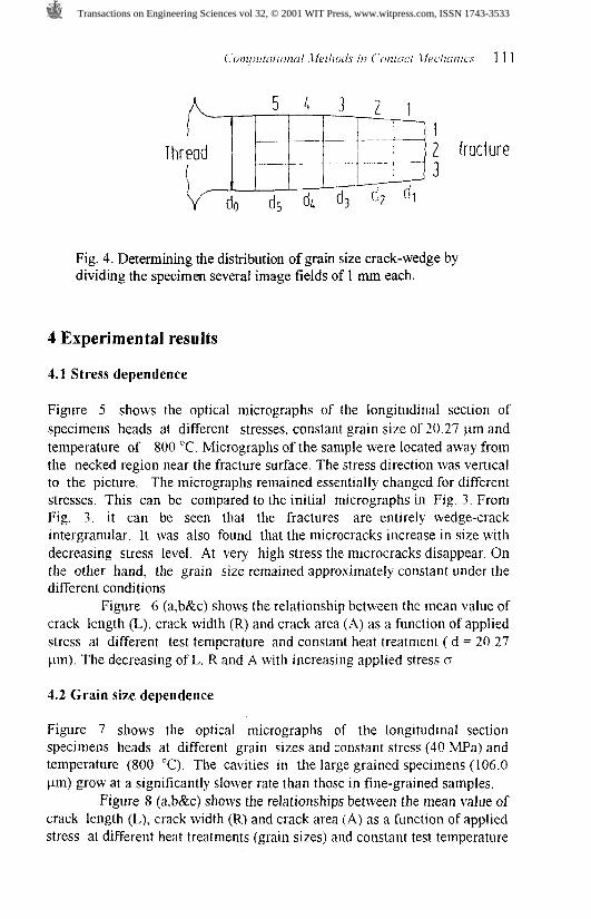
Fig. 4. Determining the distribution of grain size crack-wedge by dividing the specimen several image fields of 1 mm each.
4 Experimental results
4.1 Stress dependence
Figure 5 shows the optical micrographs of the longitudinal section of specimens heads at different stresses, constant grain size of 20.27 pm and temperature of 800 "C. Micrographs of the sample were located away from the necked region near the fracture surface. The stress direction was vertical to the picture. The micrographs remained essentially changed for different stresses. This can be compared to the initial micrographs in Fig. 3. From Fig. 3, it can be seen that the fractures are entirely wedge-crack intergranular. It was also found that the microcracks increase in size with decreasing stress level. At very high stress the microcracks disappear. On the other hand, the grain size remained approximately constant under the different conditions.
Figure 6 (a,b&c) shows the relationship between the mean value of crack length (L), crack width (R) and crack area (A) as a function of applied stress at different test temperature and constant heat treatment ( d = 20.27 pm). The decreasing of L. R and A with increasing applied stress o.
4.2 Grain size dependence
Figure 7 shows the optical micrographs of the longitudinal section specimens heads at different grain sizes and constant stress (40 MPa) and temperature (800 "C). The cavities in the large grained specimens (106.0 pm) grow at a significantly slower rate than those in fine-grained samples.
Figure 8 (a,b&c) shows the relationships between the mean value of crack length (L), crack width (R) and crack area (A) as a function of applied stress at different heat treatments (grain sizes) and constant test temperature
Transactions on Engineering Sciences vol 32, © 2001 WIT Press, www.witpress.com, ISSN 1743-3533

--- 25 50 75 l o o
Slress MPa
Fig. 5 Optical micrographs of the longitudinal section specimens heads at different stresses and constant of both grain size (20.27 pm) and temperature (800 "C).
I 2 5 50 75 100
Slress MPa
Slress MPa
Fig. 6 (a,b&c) Relationship between the mean value of crack length (L), crack width (R) and crack area (A) as a function of applied stress constant of both grain size (20.27 pm) and temperature (800 "C).
Transactions on Engineering Sciences vol 32, © 2001 WIT Press, www.witpress.com, ISSN 1743-3533

Slress MPa
Fig. 7 Optical micrographs of the longitudinal section specimens heads at different grain sizes and constant of both stress (40 MPa) and temperature (800 "C).
Stress MPa
Fig. 8 (a,b&c) Relationships between the mean value of crack length (L), crack width (R) .and crack area (A) as a function of applied stress at different grain sizes and constant test temperature 800 "C.
Transactions on Engineering Sciences vol 32, © 2001 WIT Press, www.witpress.com, ISSN 1743-3533
800 'C. The decreasing of L. R and A with increasing applied stress o. It is noticed that HT3 is the higher value of L compared with the other heat treatments. While HT3 is the lower value of R. This can be attributed to the high amount of the grain size (106.0 pm).
5 Discussion
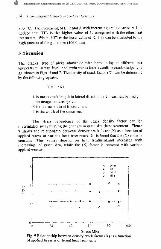
The cracks type of nickel-aluminide with boron alloy at different test temperature, stress level and grain size is intercrystalline crack-wedge type as shown in Figs. 5 and 7. The density of crack factor (X), can be determine by the following equation
L is mean crack length in lateral direction and measured by using an image analysis system,
F is the true strain at fracture. and t is the width of the specimen.
The stress dependence of the crack density factor can be investigated by evaluating the changes in grain size (heat treatment). Figure 9 shows the relationship between density crack factor (X) as a function of applied stress at various heat treatments. It is found that the (X) value is constant. This values depend on heat treattnentwd increases with increasing of grain size, while the (X) factor is constant with various applied stresses
o 2 o 40 60 80 100
Stress MFa Fig. 9 Relationship between density crack factor (X) as a fbnction of applied stress at different heat treatments
Transactions on Engineering Sciences vol 32, © 2001 WIT Press, www.witpress.com, ISSN 1743-3533
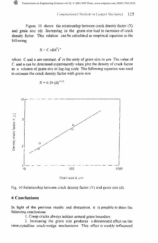
Figure 10 shows the relationship between crack density factor (X) and grain size (d). Increasing in the grain size lead to increases of crack density factor. This relation can be calculated as empirical equation as the following
where C and n are constant. d. is the unity of grain size in pm. The value of C and n can be deterimed experimently when plot the density of crack factor as a relation of grain size in log-log scale. The following equation was used to estimate the crack density factor with grain size
X = 0.29 (d) O 63
U
x- L 0 .4
U m
LC
Y U m L U
X r V ) c W n
Fig
10 100 l000
Gram size d , llnl
10 Relationship be(ween crack density factor (X) and grain size (d)
6 Conclusions
In light of the previous results and discussion, it is possible to draw the following conclusions:
1. Creep cracks always initiate around grain boundary. 2. Increasing the grain size produces a detrimental effect on the
intercrystalline crack-wedge mechanisms. This effect is weakly influenced
Transactions on Engineering Sciences vol 32, © 2001 WIT Press, www.witpress.com, ISSN 1743-3533

by the test temperature and applied stress. Increasing of the applied stress leads to increase of the crack dimensions (length, width and area).Increasing of the grain that mean increased the crack length while decreased of the crack width.
3. The crack density factor at fracture (X) is proportional to the grain size and this factor is independent of the applied stress.
4. The rate of crack growth increases with increasing of grain size. The following equation was used to estimate the crack density factor with grain size
X = O 29 (dho63 References
W. Srnarsly and L. Singheiser,"Potential of Intermetallics to Replace Superalloys for Advanced Operation Conditions in Gas Turbines", Materials for Advanced Power Engineering, Proceeding of a Cot6 held in Liege. Belgium, Oct. 1994, Part 11, pp. 173 1-1756. G. Li, J.T. Guo and Z.G. Wang,"Relationship Between Microstructure and High Cycle Fatigue Resistance of Ni3A1(B) Alloys", Materials for Advanced Power Engineering, Proceeding of a Conf. held in Liege, Belgium, Oct. 1994, Part 11, pp. 1035-1040. T. Suzuki, Y. Mishima and S. Miura."Plastic Behaviour in Ni3(AI,X) Single Crystal- Temperature, Strain rate. Orientation and Con~position", ISIJ International, Vol. 29, No. 1. 1989, pp. 1-23. J.D. Cotton. R.D. Noebe and M.J. Kaufmann,"The Effect of Chromium on NiAl Intermetallic Alloys: Part I. Microstructures and Mechanical Properties", Intermetallics I , 1993, pp. 3-20. R. Darolia,"In Ordered Intermetallic- Physical Metallurgy and Mechanical Behaviour", ed. C.L. Liu et al.. Kluwer Academic Publishers, the Netherlands, 1992, pp. 679-687. A..M. Hashem,"Influence of the Heat Treatment on Creep Behaviour of Nickel Aluminide with Boron", Advanced Performance Materials 4, USA, pp. 9-23, 1997. Z.D. Jastrzebski,"The nature and Properties of Engineering Materials", John Willy & Sons, Inc., 1988, p. 373. G.H. Edward and M.F. Ashby,"Intergranular Fracture During Power- Law Creep", Acta Metallurgica, vol. 27, 1979, pp. 1505-1518. H.-W. Walkenhorst,"Ermittlung des Wachstumsverhaltens interkristalliner Risse bei Zeitstandeanspruchung austenitischer Staehle", Ph. D Thesis. LFW-RWTH Aachen, Germany, 1991.
[l01 R.W. Evans and B Wilshire,"Creep of Metals and Alloys", Institute of Metals, 1985, pp. 157-174.
[ l l ] A.M. Hashem, D. Goldschnlidtand E. El-Magd, " Cavitation Damage of the Single-Crystal Nickel-Base Superalloy SRR99 during Creep at 850 "C". Jounal of Mat.-wiss U. Werkstofftech. 25. 1994. pp 133-138
Transactions on Engineering Sciences vol 32, © 2001 WIT Press, www.witpress.com, ISSN 1743-3533
Copyright © 2022 FDOKUMEN