Stability of waterfront retaining wall subjected to pseudo-static earthquake forces
25
Journal of Earthquake and Tsunami, Vol. 2, No. 2 (2008) 107–131 c World Scientific Publishing Company STABILITY OF WATERFRONT RETAINING WALL SUBJECTED TO PSEUDO-DYNAMIC EARTHQUAKE FORCES AND TSUNAMI SYED MOHD. AHMAD Department of Civil Engineering, Indian Institute of Technology Bombay, Mumbai, India DEEPANKAR CHOUDHURY Department of Civil Engineering, Indian Institute of Technology Bombay, Mumbai, India [email protected] Accepted 30 July 2008 The paper pertains to a study in which the waterfront retaining wall has been analyzed for its stability when it is exposed to the forces jointly coming from an earthquake and tsunami. Closed form solutions following the simple limit equilibrium principles have been proposed. For the calculation of the seismic passive earth pressure and the wall inertia force, pseudo-dynamic approach has been considered, while the hydrodynamic and the tsunami wave pressures have been calculated using different approximating solutions available in literature. The results presented in the sliding and overturning modes of failure of the wall show that the stability of the wall gets seriously challenged when it gets jointly exposed to the effects of the tsunami and earthquake. About 92% decrease is observed in the value of the factor of safety in sliding mode of failure of the wall as the ratio of tsunami wave height to the upstream still water height increases from 0 to 1.5. Also, the critical mode of failure of the wall has been found to be that of the overturning. Effect of different parameters involved in the analysis has also been studied and it has been observed that quite a few of them like k h ,kv , φ, δ, ru have a significant effect on the stability of the wall. Comparison with a previously existing methodology using pseudo-static approach suggests that the present pseudo-dynamic approach is more realistic and comparatively less conservative and hence can be used as a handy simple economic method for the design of the waterfront retaining walls exposed to the combined effects of earthquake and tsunami. Keywords : Seismic passive earth pressure; tsunami; hydrodynamic pressure; wall inertia; design; sliding; overturning; factor of safety. 1. Introduction The damage of many waterfront retaining structures in general and of the water- front retaining walls in particular during an earthquake or otherwise due to the disturbing forces coming from the impact of the breaking waves or due to tsunami (which may or may not have been triggered by the earthquake) is well documented in the literature. The recent South Asian earthquake of 2004 which triggered a massive tsunami wave caused havoc and large scale damage to several waterfront 107
Transcript of Stability of waterfront retaining wall subjected to pseudo-static earthquake forces

November 21, 2008 14:40 WSPC/238-JET 00028
Journal of Earthquake and Tsunami, Vol. 2, No. 2 (2008) 107–131c© World Scientific Publishing Company
STABILITY OF WATERFRONT RETAINING WALLSUBJECTED TO PSEUDO-DYNAMIC EARTHQUAKE
FORCES AND TSUNAMI
SYED MOHD. AHMAD
Department of Civil Engineering,Indian Institute of Technology Bombay, Mumbai, India
DEEPANKAR CHOUDHURY
Department of Civil Engineering,Indian Institute of Technology Bombay, Mumbai, India
Accepted 30 July 2008
The paper pertains to a study in which the waterfront retaining wall has been analyzedfor its stability when it is exposed to the forces jointly coming from an earthquake andtsunami. Closed form solutions following the simple limit equilibrium principles havebeen proposed. For the calculation of the seismic passive earth pressure and the wallinertia force, pseudo-dynamic approach has been considered, while the hydrodynamicand the tsunami wave pressures have been calculated using different approximatingsolutions available in literature. The results presented in the sliding and overturningmodes of failure of the wall show that the stability of the wall gets seriously challengedwhen it gets jointly exposed to the effects of the tsunami and earthquake. About 92%decrease is observed in the value of the factor of safety in sliding mode of failure of thewall as the ratio of tsunami wave height to the upstream still water height increasesfrom 0 to 1.5. Also, the critical mode of failure of the wall has been found to be thatof the overturning. Effect of different parameters involved in the analysis has also beenstudied and it has been observed that quite a few of them like kh, kv, φ, δ, ru have asignificant effect on the stability of the wall. Comparison with a previously existingmethodology using pseudo-static approach suggests that the present pseudo-dynamicapproach is more realistic and comparatively less conservative and hence can be used asa handy simple economic method for the design of the waterfront retaining walls exposedto the combined effects of earthquake and tsunami.
Keywords: Seismic passive earth pressure; tsunami; hydrodynamic pressure; wall inertia;design; sliding; overturning; factor of safety.
1. Introduction
The damage of many waterfront retaining structures in general and of the water-front retaining walls in particular during an earthquake or otherwise due to thedisturbing forces coming from the impact of the breaking waves or due to tsunami(which may or may not have been triggered by the earthquake) is well documentedin the literature. The recent South Asian earthquake of 2004 which triggered amassive tsunami wave caused havoc and large scale damage to several waterfront
107

November 21, 2008 14:40 WSPC/238-JET 00028
108 S. M. Ahmad & D. Choudhury
structures, including the retaining walls. There have been instances in the pastwhen structures having been built safely, without making consideration for suchrather rare but important forces, have failed meekly when faced with such eventu-alities comprising severe conditions. Such failures prompt the designers and engi-neers to have an understanding about the behavior of these waterfront retainingstructures under severe conditions. Under static conditions, for a typical water-front retaining wall, supporting a dry backfill, the only disturbing force for thestability of the wall is the lateral earth pressure coming from the downstream side,while on the upstream side, the destabilization comes due to the hydrostatic pres-sure. However, further instability to the wall would be caused in the event of anearthquake, which gives rise to the development of additional forces–the seismiccomponent of the lateral earth pressure from the downstream side and the hydrody-namic pressure, which, depending upon the case may or may not be on both theupstream and downstream sides of the wall. The earthquake may be followed bya tsunami as well, which would further add to the instability of the wall. A com-bination of all these forces/pressures poses serious challenge to the stability of thewall. However, in spite of all the importance these waterfront retaining walls have,the area of understanding the behaviour of these retaining walls when exposed tosuch severe conditions does not seem to be well researched. The literature archivesshow that there have not been many studies in the past, in which the stabilityand the behavior of such waterfront retaining walls had been assessed under thementioned combination of forces/pressures. Whatever is present in the literatureis either by considering only one force/pressure or just a combination of a few ofthese forces/pressures at a time, except for the work reported by Choudhury andAhmad (2007a) who considered all these forces/pressures, but in which the seis-mic earth pressure was calculated using the conventional pseudo-static approach,which can be regarded to be too conservative as it has got several drawbacks ashas been reported by Steedman and Zeng (1990), Choudhury and Nimbalkar (2005,2006, 2007), Choudhury and Ahmad (2008), Ahmad and Choudhury (2008), andNimbalkar and Choudhury (2008). The effect of the hydrodynamic pressure alongwith the seismic active earth pressure was studied by Ebeling and Morrison (1992)and Choudhury and Ahmad (2007b, 2008). The destabilizing effects of the hydrody-namic pressure on the waterfront structures have also been reported by Nozu et al.,(2004); while Matsuo and Ohara (1965) analyzed the seismic behavior of the quaywalls due to dynamic pore water pressure. Similarly, with respect to the seismicearth pressure, the Mononobe-Okabe theory proposed by Okabe and Mononobeand Matsuo (see Kramer, 1996), in which the seismic forces are considered using apseudo-static approach, is widely used worldwide. Apart from this classic theory,various other researchers over the years have tried to develop better understandingof the lateral earth pressure problem for rigid walls supporting dry backfills underseismic conditions and have adopted different approaches in proposing different the-ories, viz., the limit equilibrium method by Richards and Elms (1979), Choudhuryand Nimbalkar (2006, 2007); finite element techniques by Gazetas et al., (2004); two

November 21, 2008 14:40 WSPC/238-JET 00028
Stability of Waterfront Retaining Wall 109
degree of freedom mass-spring-dashpot model by Choudhury and Chatterjee (2006).But none of these described approaches, presented for the calculation of the seismicearth pressures, considered the effect of hydrodynamic pressure. Similarly, adoptingdifferent approaches and approximations, various researchers have come up with theexpressions for the estimation of the tsunami wave pressure — for example, Fukuiet al., (1962) (see Mizutani and Imamura (2001)) proposed an expression for thecalculation of the dynamic component of the tsunami wave pressure by consid-ering the wave celerity, while CRATER (2006) approximated the tsunami wavepressure to be equal to the hydrostatic pressure equivalent to thrice the height ofthe water. Yeh (2006) also proposed solutions for the interaction of tsunami withcoastal defence structures and maximum fluid forces on the tsunami run up zone.Other studies which considered the impact of wave breaking forces/pressures on thevertical and sloping walls, and other structures are due to Kirkgoz (1995), Mullerand Whittaker (1993) etc. The discussion about the literature apart from throwinglight on the importance and relevance the waterfront retaining walls to the civilengineers, also highlighted some of the research gaps and the rather approximat-ing pseudo-static technique with reference to the estimation of the seismic passiveearth pressure–which as already discussed suffers from serious drawbacks of beingtoo conservative and thus when adopted does not give a correct estimate of theseismic earth pressure — existing in the present day methodologies adopted for thedesign of water retaining walls in general and in particular for the specific cases ofthe wall, in which the effect of the tsunami, hydrodynamic pressure, along with theearthquake has been considered simultaneously. Thus, through the present study,an attempt has been made to bridge the gap and propose complete design solu-tions for the study of the stability aspects of a typical waterfront retaining wall,exposed to an earthquake and tsunami simultaneously, including the hydrodynamicpressure, by proposing closed form solutions using the limit equilibrium approach,and in which care has been taken to make use of the pseudo-dynamic approach— which is a better way of calculating the seismic earth pressures. It is also tobe mentioned that generally there is a significant time gap between the occurrenceof the primary shock of an earthquake and a tsunami. However, after-shocks arecommon especially after a big earthquake and some of these may well coincide withthe arrival of a tsunami. To address this issue, the combined effects of earthquakeforces and tsunami are considered in the present analysis.
2. Methodology Adopted
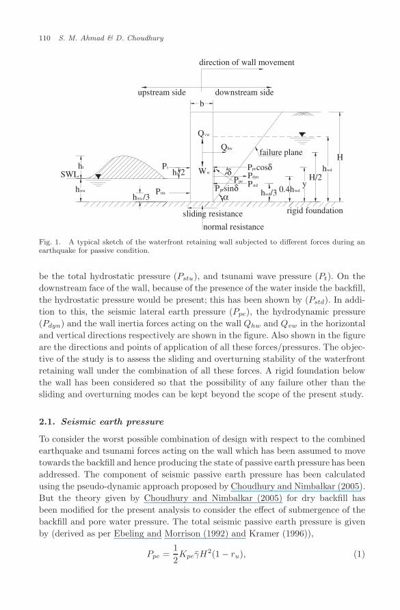
Figure 1 shows a typical vertical face rigid retaining wall situated at the waterfront.The width of the wall is ‘b’, and the height of the wall is ‘H ’. The backfill, which isto the full height of the wall, is submerged with water to a height ‘hwd’, and it isconsidered that the ground surface of the backfill is horizontal. The upstream faceof the wall holds water to a height ‘hwu’, and a tsunami water wave having a height‘ht’; thus, the corresponding pressure/force due to hwu and ht would respectively
November 21, 2008 14:40 WSPC/238-JET 00028
110 S. M. Ahmad & D. Choudhury
hwu /3
yH/2
Hhwd
SWL ht/2Ptht
hwu
rigid foundation
0.4hwdPpesinδPpe
δ
Qhw
Ww
downstream sideupstream side
direction of wall movement
normal resistance
sliding resistance
Pstd
Pstu
Qvw
hwd/3
Pdyn
Ppecosδ
b
α
failure plane
Fig. 1. A typical sketch of the waterfront retaining wall subjected to different forces during anearthquake for passive condition.
be the total hydrostatic pressure (Pstu), and tsunami wave pressure (Pt). On thedownstream face of the wall, because of the presence of the water inside the backfill,the hydrostatic pressure would be present; this has been shown by (Pstd). In addi-tion to this, the seismic lateral earth pressure (Ppe), the hydrodynamic pressure(Pdyn) and the wall inertia forces acting on the wall Qhw and Qvw in the horizontaland vertical directions respectively are shown in the figure. Also shown in the figureare the directions and points of application of all these forces/pressures. The objec-tive of the study is to assess the sliding and overturning stability of the waterfrontretaining wall under the combination of all these forces. A rigid foundation belowthe wall has been considered so that the possibility of any failure other than thesliding and overturning modes can be kept beyond the scope of the present study.
2.1. Seismic earth pressure
To consider the worst possible combination of design with respect to the combinedearthquake and tsunami forces acting on the wall which has been assumed to movetowards the backfill and hence producing the state of passive earth pressure has beenaddressed. The component of seismic passive earth pressure has been calculatedusing the pseudo-dynamic approach proposed by Choudhury and Nimbalkar (2005).But the theory given by Choudhury and Nimbalkar (2005) for dry backfill hasbeen modified for the present analysis to consider the effect of submergence of thebackfill and pore water pressure. The total seismic passive earth pressure is givenby (derived as per Ebeling and Morrison (1992) and Kramer (1996)),
Ppe =12Kpeγ̄H
2(1 − ru), (1)

November 21, 2008 14:40 WSPC/238-JET 00028
Stability of Waterfront Retaining Wall 111
where ru = pore pressure ratio, defined as the ratio of excess pore pressure to theinitial vertical stress, incorporation of which is a simplified way (as per Ebeling andMorrison, (1992)) of simulating the effect of the excess pore pressure generated dueto cyclic shaking of the soil during an earthquake; Kpe = the seismic passive earthpressure coefficient, obtained by using the similar methodology of Choudhury andNimbalkar (2005),
Kpe =1
tanαsin(α + φ)
cos(δ + φ+ α)− kh
2π2 tanα
(TVs
H
)sin(α+ φ)
cos(δ + φ+ α)m1
− kv
2π2 tanα
(TVp
H
)sin(α+ φ)
cos(δ + φ+ α)m2, (2)
with
m1 = 2π cos 2π(t
T− H
TVs
)+(TVs
H
)[sin 2π
(t
T− H
TVs
)− sin 2π
(t
T
)],
(3)
m2 = 2π cos 2π(t
T− H
TVp
)+(TVp
H
)[sin 2π
(t
T− H
TVp
)− sin 2π
(t
T
)],
(4)
and α = angle which the failure wedge plane makes with the horizontal at the baseof the wall; δ = wall friction angle; φ = soil friction angle; t = time; T = period oflateral shaking; Vp = velocity of the primary wave propagating through the backfillsoil; and Vs = velocity of the shear wave propagating through the backfill soil. Also,in Eq. (1), γ̄ is the unit weight of the backfill soil, modified due to the submergenceof water and is given by (Kramer (1996)),
γ̄ =(hwd
H
)2
γsat +
(1 −
(hwd
H
)2)γd, (5)
where γsat and γd = the saturated and dry unit weights of the soil respectively. Aclose look at Eq. (5) shows that for full submergence of the backfill (when hwd = H),γ̄ = γsat; while for a dry backfill case (when hwd = 0), γ̄ = γd.
It is to be noted that following the methodology proposed by Choudhury andNimbalkar (2005), the expression for the calculation of the seismic passive earthpressure coefficient (Eq. (2)) has been optimized for a minimum value of the seis-mic passive earth pressure coefficient with respect to α and t/T . It is however, tobe mentioned that to account for the submergence of the backfill and the presenceof the pore pressure, both of which would have an effect on the seismic accelerationcoefficients in the horizontal and vertical directions (kh and kv), the approach fol-lowed by the Ebeling and Morrison (1992), has been adopted in the present study,according to which, the horizontal seismic acceleration coefficient (kh) is given as,
k∗h =γsat
γ̄(1 − ru)kh. (6)

November 21, 2008 14:40 WSPC/238-JET 00028
112 S. M. Ahmad & D. Choudhury
Minima of the Eq. (2) is thus found by replacing kh with k∗h given by Eq. (6). Theeffect of the submergence and the pore pressure ratio on the value of the seismicacceleration coefficient in the vertical direction (kv) gets indirectly accounted for inthe present study because of the dependence of this kv on the seismic accelerationcoefficient in the horizontal direction (kh) either by assuming kv = kh/2 or kv = kh.For initiating the process of optimization of Eq. (2), so as to find the minimumvalue of the seismic passive earth pressure coefficient (Kpe), the initial values ofthe parameters α and t/T , in whose respect the optimization is made, have beentaken to be equal to αMO and 1/T respectively; in which αMO is the angle whichthe failure plane makes with the horizontal at the base of the wall calculated usingthe Mononobe-Okabe approach as (Kramer (1996)),
αMO = ψ − φ + tan−1
[− tan(φ+ ψ) + C1E
C2E
], (7)
where
C1E =√
tan(φ − ψ)[tan(φ− ψ) + cot(φ− ψ)][1 + tan(δ + ψ) cot(φ− ψ)], (8)
C2E = 1 + {tan(δ + ψ)[tan(φ− ψ) + cot(φ− ψ)]}, (9)
with ψ = seismic inertia angle calculated as (Ebeling and Morrison (1992)),
ψ = tan−1 k∗h(1 − kv)
. (10)
2.2. Seismic inertia forces on the wall
Like the seismic passive earth pressure, the seismic inertia forces Qhw and Qvw inthe horizontal and vertical directions respectively, generated in the wall due to theearthquake are calculated using the pseudo-dynamic approach given by Choudhuryand Nimbalkar (2005). For the purpose of deriving the expressions for the wallinertia forces, the basic wall model chosen is as shown in Fig. 2 following the modelgiven by Choudhury and Nimbalkar (2005), which was modified by Choudhury andAhmad (2008). If ahw and avw are respectively the amplitudes of the harmonichorizontal and vertical seismic accelerations in the wall, then the correspondingaccelerations in the horizontal and vertical directions, at depth z and time t, belowthe top of the wall are expressed as,
ahw(z, t) = ahw sinω(t− H − z
Vsw
), (11)
and
avw(z, t) = avw sinω(t− H − z
Vpw
). (12)
The mass of the thin rectangular element of the wall of thickness dz is,
mw(z) =γc
gbdz, (13)

November 21, 2008 14:40 WSPC/238-JET 00028
Stability of Waterfront Retaining Wall 113
rigid foundation
Ppe
α
Qhw
Ww
Qvw
b
α
failure plane
Qv
W
Qh
H
z
dz
Vsw Vpw Vs Vp
φ F
direction of wall movement
Fig. 2. Model retaining wall considered for computation of the pseudo-dynamic passive earthpressure considering both soil and wall inertia.
where γc is the unit weight of the wall material. The total seismic inertia force inthe horizontal direction (Qhw) for the entire wall is given by,
Qhw =∫ H
0
mw(z)ahw(z, t). (14)
Substituting for mw(z) and ahw(z, t) from Eqs. (13) and (11) and simplifying,the expression for total seismic inertia force on the wall in the horizontal directionis given as
Qhw =TVswγcbahw
g
(12π
)[− cos 2π
t
T+ cos 2π
(t
T− H
TVsw
)]. (15)
Similarly, the expression for the total seismic inertia force on the wall in thevertical direction (Qvw) would be
Qvw =TVpwγcbavw
g
(12π
)[− cos 2π
t
T+ cos 2π
(t
T− H
TVpw
)], (16)
where, Vsw and Vpw are respectively the shear and primary wave velocities travel-ing through the material of the wall (which is concrete in the present case). Thedirections of these inertia forces shown in Fig. 2, are such that they give the worstpossible condition with respect to the stability of the wall in sliding and overturningmodes of failure for the design purpose. The total seismic inertia force on the wallin the vertical direction (Qvw) is assumed to act at half the width of the wall sec-tion (i.e. at b/2 from either sides), while the total seismic inertia force on the wall

November 21, 2008 14:40 WSPC/238-JET 00028
114 S. M. Ahmad & D. Choudhury
in the horizontal direction (Qhw) is assumed to act at the mid-height of the wall(i.e. at H/2 from the base of the wall). Also, it has been assumed in the presentstudy that at a particular instant, both the backfill soil mass and the retainingwall shake simultaneously with the same earthquake intensities (i.e. ahw = ah; andavw = av – where ah and av are the horizontal and vertical seismic accelerations ofthe backfill soil).
2.3. Forces on the wall due to water on the upstream face
Two different types of water conditions have been considered on the upstreamface of the wall viz., water of height ‘hwu’ (supposedly to be in static condition),and tsunami water of height ‘ht’ (supposedly to be in dynamic condition). Thecalculations regarding each of these two is described in the next two sections.
2.3.1. Pressure due to water height ‘hwu’
This water height would be exerting a hydrostatic pressure (Pstu) on the wall,calculated by,
Pstu =12γw(hwu)2 (17)
acting at a height of hwu
3 from the base of the wall.
2.3.2. Pressure due to tsunami water of height ‘ht’
The literature archives showed that there are two methodologies in vogue for thecalculation of the pressure due to tsunami wave on a vertical wall, namely themethodology adopted by CRATER (2006) and the other one proposed by Fukuiet al., (1962). According to the theory adopted by CRATER (2006), the pressuredue to a tsunami wave (PtC) would be,
PtC = 4.5γw (ht)2. (18)
This expression has also been used by the US Army Corps of Engineers (1990).However, it does not take into account the velocity of the tsunami wave with whichit is traveling. The simplified expression for the calculation of the pressure due totsunami (PtF ) by using the other methodology originally proposed by Fukui et al.,(1962), which also accounts for the velocity of the tsunami wave, is
PtF =12γw(hwu)2
[(ht
hwu
)2
+ 2(ht
hwu
)+K
], (19)
where K is a constant and is equal to 0 when ht/hwu = 0 (i.e. no tsunami); whilefor any other value of ht/hwu, the value of K is taken as 0.12.
Since, it is difficult to assess which theory is best suited for the type of theproblem being analyzed in the present study, it has been decided to use and present

November 21, 2008 14:40 WSPC/238-JET 00028
Stability of Waterfront Retaining Wall 115
results by using both the theories. It is also to be noted that the tsunami pressure,calculated by any of the two theories adopted, is considered to act at the mid heightof the tsunami water height ‘ht’ (i.e. at a height of (hwu + 0.5ht) measured fromthe base of the wall).
2.4. Forces on the wall due to water on the downstream face
The downstream face of the wall has backfill which is submerged due to water toa height ‘hwd’. The hydrostatic pressure due to this water would essentially be thesame as calculated by Eq. (17), except for the fact that the unit weight of the soilis to be replaced by an equivalent unit weight γwe, given by (Ebeling and Morrison,(1992)),
γwe = γw + (γ̄ − γw) ru, (20)
thus, the total hydrostatic pressure acting on the wall from the downstream side(Pstd) is
Pstd =12γwe(hwd)2. (21)
Like the hydrostatic pressure from the upstream face of the wall, this pressurewould also be acting at 1/3 the height of the water on the downstream face. Dur-ing an earthquake, the shaking of the water present in between the soil grains ofthe backfill soil (Kramer, (1996)) would give rise to the development of the addi-tional hydrodynamic pressure (Pdyn), which, following the methodology proposedby Westergaard (1933), is calculated as,
Pdyn =712khγw (hwd)
2 (22)
This hydrodynamic pressure would be acting at 0.4hwd (Westergaard, (1933)) andit has been considered that this pressure would act in the same direction as is thedirection of the wall movement (as shown in Fig. 1). This has been done so as tohave a worst possible scenario with respect to the stability of the wall.
It is to be mentioned, that owing to the nature of the expression which catersto the effect of the tsunami wave pressure coming from the upstream face, anddue to the relatively small height of the water present on the upstream face ‘hwu’,(supposedly to be under static conditions), the generation of the hydrodynamicpressure on this side of the wall has not been considered.
3. Stability of the Wall
The wall under consideration is assessed in terms of its stability in the sliding andoverturning modes of failure. The derivations of the expressions of the factor ofsafety, which give idea about the stability of the wall in these two modes of failure,are presented in the next few sections.
November 21, 2008 14:40 WSPC/238-JET 00028
116 S. M. Ahmad & D. Choudhury
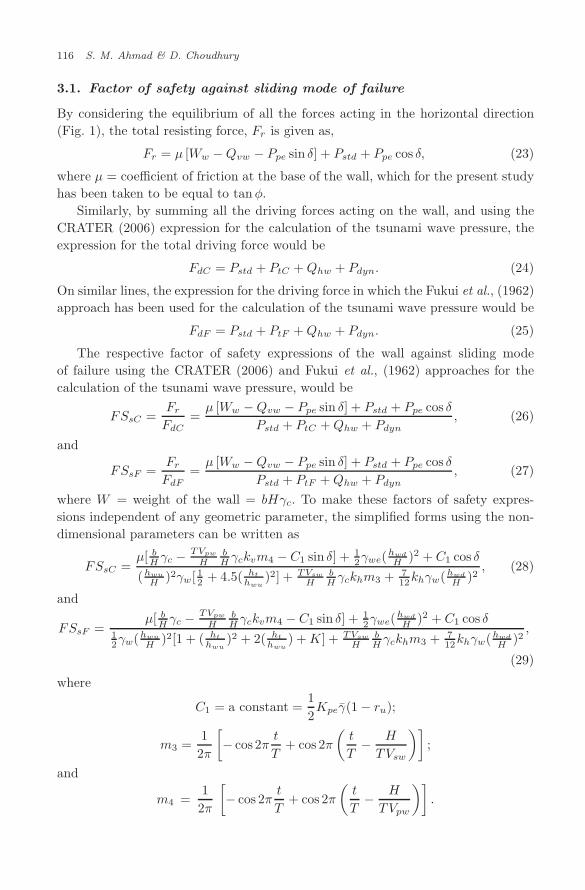
3.1. Factor of safety against sliding mode of failure
By considering the equilibrium of all the forces acting in the horizontal direction(Fig. 1), the total resisting force, Fr is given as,
Fr = µ [Ww −Qvw − Ppe sin δ] + Pstd + Ppe cos δ, (23)
where µ = coefficient of friction at the base of the wall, which for the present studyhas been taken to be equal to tanφ.
Similarly, by summing all the driving forces acting on the wall, and using theCRATER (2006) expression for the calculation of the tsunami wave pressure, theexpression for the total driving force would be
FdC = Pstd + PtC +Qhw + Pdyn. (24)
On similar lines, the expression for the driving force in which the Fukui et al., (1962)approach has been used for the calculation of the tsunami wave pressure would be
FdF = Pstd + PtF +Qhw + Pdyn. (25)
The respective factor of safety expressions of the wall against sliding modeof failure using the CRATER (2006) and Fukui et al., (1962) approaches for thecalculation of the tsunami wave pressure, would be
FSsC =Fr
FdC=µ [Ww −Qvw − Ppe sin δ] + Pstd + Ppe cos δ
Pstd + PtC +Qhw + Pdyn, (26)
and
FSsF =Fr
FdF=µ [Ww −Qvw − Ppe sin δ] + Pstd + Ppe cos δ
Pstd + PtF +Qhw + Pdyn, (27)
where W = weight of the wall = bHγc. To make these factors of safety expres-sions independent of any geometric parameter, the simplified forms using the non-dimensional parameters can be written as
FSsC =µ[ b
H γc − TVpw
HbH γckvm4 − C1 sin δ] + 1
2γwe(hwd
H )2 + C1 cos δ(hwu
H )2γw[12 + 4.5( ht
hwu)2] + TVsw
HbH γckhm3 + 7
12khγw(hwd
H )2, (28)
and
FSsF =µ[ b
H γc − TVpw
HbH γckvm4 − C1 sin δ] + 1
2γwe(hwd
H )2 + C1 cos δ12γw(hwu
H )2[1 + ( ht
hwu)2 + 2( ht
hwu) +K] + TVsw
HbH γckhm3 + 7
12khγw(hwd
H )2,
(29)
where
C1 = a constant =12Kpeγ̄(1 − ru);
m3 =12π
[− cos 2π
t
T+ cos 2π
(t
T− H
TVsw
)];
and
m4 =12π
[− cos 2π
t
T+ cos 2π
(t
T− H
TVpw
)].

November 21, 2008 14:40 WSPC/238-JET 00028
Stability of Waterfront Retaining Wall 117
3.2. Factor of safety against overturning mode of failure
By summing the moments of all the resisting forces about the heel of wall, thesimplified factor of safety expression in the non-dimensional form, obtained by boththe CRATER (2006) and Fukui et al., (1962) approaches for the calculation of thetsunami wave pressure respectively are
FSoC =
12 ( b
H )2γc − 12
TVpw
H ( bH )2γckvm4 + 1
6γwe(hwd
H )3
+ 16 γ̄(1 − ru) cos δ[3(Kpe −Kp)Hd
H +Kp]
γw(hwu
H )3[16 + 4.5( ht
hwu)2(1
2ht
hwu+ 1)]
+ 12
TVsw
HbH γckhm3 + 2.8
12 khγw(hwd
H )3
, (30)
and
FSoF =
12 ( b
H )2γc − 12
TVpw
H ( bH )2γckvm4 + 1
6γwe(hwd
H )3
+ 16 γ̄(1 − ru) cos δ[3(Kpe −Kp)Hd
H +Kp]
γw(hwu
H )3[16 + 12{( ht
hwu)2 + 2( ht
hwu) +K}(1
2ht
hwu+ 1)]
+ 12
TVsw
HbH γckhm3 + 2.8
12 khγw(hwd
H )3
, (31)
where, Hd = the point of application of the dynamic component of the total seismicpassive earth pressure (Ppe), and is calculated using the methodology proposed byNimbalkar (2007) as
Hd = H −
2π2H2(m cosωξ + n cosωκ) + 2πH(λm sinωξ + ηn sinωκ)
−λ2m(cosωξ − cosωt) − η2n(cosωξ − cosωt)
2π2H(m cosωξ + n cosωκ) + π(λm sinωξ + ηn sinωκ)− π(λm+ ηn) sinωt
, (32)
with m = λkh cos(α + φ);n = ηkv sin(α + φ);ω = 2π/T ; ξ = t − H/Vs;κ =t − H/Vp;λ = TVs; and η = TVp. Also, in Eqs. (30) and (31), Kp is the passiveearth pressure coefficient under static conditions, calculated using the Coulomb’stheory by the following expression (see Kramer (1996)),
Kp =cos2 φ
cos δ[1 −
√sin(δ+φ) sin φ
cos δ
]2 . (33)
The total passive earth pressure under static conditions (Pp), calculated using thisKp is considered to act at 1/3 the height of the wall (i.e. H/3), measured from thebase.
4. Results and Discussions
The results obtained using equations for the factors of safety [Eqs. (28), (29), (30),and (31)], along with a critical discussion, which give an idea about the stability ofthe wall in sliding and overturning modes of failure, for different combinations of

November 21, 2008 14:40 WSPC/238-JET 00028
118 S. M. Ahmad & D. Choudhury
the parameters involved in these factor of safety expressions are presented in thissection. The values and/or ranges of the different parameters chosen for the studyare: b/H = 0.2;hwu/H = 0.4;hwd/H = 0.0, 0.25, 0.50, 0.75, and 1.00; ht/hwu = 0,0.375, 0.75, 1.125, and 1.5; φ = 25◦, 30◦, 35◦, and 40◦; δ = −φ/2, 0, and φ/2; kh =0, 0.1, 0.2, and 0.3; kv = 0, kh/2, and kh; ru = 0, 0.2, and 0.4; T = 0.2 s, 0.3 s, 0.4 s,and 0.5 s; γc = 25 kN/m3; γw = 10 kN/m3; γsat = 19 kN/m3; γd = 16 kN/m3;Vs = 100 m/s (which, as per Das (1993) is within the range of the practical rangechosen for the granular soils); Vp = 187 m/s, which is calculated using the relationVp/Vs =
√2(1 − ν)/(1 − 2ν) (as per Das (1993)) by assuming Poisson’s ratio of 0.3.
On considering the height of the wall H = 10 m, T = 0.3 s (see Prakash (1981)),the non-dimensional parameters H/TVs and H/TVp would respectively be equal to0.3 and 0.16. Similarly, by suitably choosing the values of the shear and primarywave velocities propagating through the wall Vsw = 2500 m/s and Vpw = 3900 m/s,the other non-dimensional parametersH/TVsw and H/TVpw are equal to 0.012 and0.0077 respectively.
4.1. Effect of the horizontal seismic acceleration coefficient ‘kh’and tsunami water height ‘ht’
Figures 3(a) and 3(b) present typical variations of the factor of safety in respectivelysliding and overturning modes of failure of the wall with horizontal seismic accel-eration coefficient (kh) for different values of the ratio of tsunami water height (ht)to height of the still water on the upstream face (hwu). It is observed that with anincrease in the value of the horizontal seismic acceleration coefficient (kh), the valueof the factor of safety obtained by using either of the two approaches, describedwith respect to the calculation of the tsunami wave pressure, decreases drastically.As an illustration, for a value of ht/hwu of 1.5 and by using the CRATER (2006)approach for the calculation of the tsunami wave pressure, the factor of safety insliding mode of failure of the wall decreases from about 7.20 to 3.10 when the valueof the horizontal seismic acceleration coefficient (kh) is increased from 0.0 to 0.3(Fig. 3a). The same trend of a decrease in the value of the factor of safety in slidingmode of failure is observed for other values of ht/hwu. By using the Fukui et al.,(1962) approach for the calculation of the tsunami wave pressure, the values ofthe factor of safety in sliding mode of failure are higher than those obtained byCRATER (2006) approach. This may be attributed to the fact that the CRATER(2006) approach tends to be bit conservative. Another important observation whichcan be made from this graph is that as the value of the ht/hwu is increased from0 to 1.5, there is a drastic decrease in the value of the factor of safety. For exam-ple, for a particular value of the horizontal seismic acceleration coefficient (kh) of0.1, the factor of safety in sliding mode of failure is about 22 when there is notsunami (i.e. ht/hwu = 0.0); while the same gets reduced to a value of 1.7 whenthe ht/hwu = 1.5. This typical result showcases the importance of considering thepressure due to tsunami wave while designing the section of the wall situated atthe waterfront, especially in the areas which are susceptible to earthquakes. Similar

November 21, 2008 14:40 WSPC/238-JET 00028
Stability of Waterfront Retaining Wall 119
0.0 0.1 0.2 0.30
5
10
15
20
25
30
kv=k
h/2; T=0.3 s; r
u=0.2
γsat
=19kN/m3; γ
d=16kN/m
3; γ
c=25kN/m
3; γ
w=10kN/m
3
Vs=100m/s;Vp=187m/s; Vsw=2500m/s;Vpw=3900m/s
H=10m; b/H=0.2; hwu
/H=0.4; hwd
/H=0.75; !=300; δ=φ/2
FS sC
,FS sF
Horizontal seismic acceleration coefficient, kh
ht/h
wuCRATER Fukui et al.
[2006] [1962]0.375 0.750 1.125 1.500
curve overlapfor CRATER [2006] andFukui et al. [1962] for no tsunami
Fig. 3(a). Factor of safety in sliding mode of failure for different ht/hwu values.
0.0 0.1 0.2 0.30
5
10
15
20
25
30
γw=10kN/m3; k
v=k
h/2; T=0.3 s; r
u=0.2
γsat
=19kN/m3; γd=16kN/m3; γ
c=25kN/m3
Vs=100m/s;Vp=187m/s; Vsw=2500m/s;Vpw=3900m/s
H=10m; b/H=0.2; hwu
/H=0.4; hwd
/H=0.75; φ=300; δ=φ/2
FS oC
,FS oF
Horizontal seismic acceleration coefficient, kh
ht/h
wuCRATER Fukui et al.
[2006] [1962]0.375 0.750 1.125 1.500
curve overlapfor CRATER [2006] andFukui et al. [1962] for no tsunami
Fig. 3(b). Factor of safety in overturning mode of failure for different ht/hwu values.
trends are observed for the factor of safety of the wall in overturning mode of failure(Fig. 3b), however, the corresponding values are lower than those obtained in thesliding mode of failure of the wall — thus, setting up the critical mode of failure ofthe wall under the mentioned forces/pressures to be the overturning mode.
4.2. Effect of variation in the level of submergence
of the backfill ‘hwd’
The effect of the change in the level of submergence of the backfill, which is rep-resented in the present study in terms of the non-dimensional parameter ‘hwd/H ’,on the stability of the wall, is presented in Figs. 4(a) and 4(b) for the sliding and

November 21, 2008 14:40 WSPC/238-JET 00028
120 S. M. Ahmad & D. Choudhury
0.0 0.1 0.2 0.30
4
8
12
kv=k
h/2; T =0.3s; r
u=0.2
Vs=100m/s; Vp=187m/sγ
sat=19kN/m
3; γ
d=16kN/m
3; γ
c=25kN/m
3; γ
w=10kN/m
3F
S sC,F
S sF
Horizontal seismic acceleration coefficient, kh
hwd
/H CRATER Fukui et al.
[2006] [1962]0.00 0.25 0.50 075 1.00
Vsw=2500m/s;Vpw=3900m/s
H=10m; b/H=0.2; hwu
/H=0.4; ht/h
wu=1.125; φ=30
0; δ=φ/2
Fig. 4(a). Factor of safety in sliding mode of failure for different hwd/H values.
overturning modes of failure of the wall respectively. It is observed that as the levelof submergence is increased, the factor of safety, both in the sliding and modesof failure, increases. For example, for dry backfill case (i.e. hwd/H = 0), the fac-tor of safety in the sliding mode of failure of the wall (Fig. 4(a)), by adoptingthe CRATER (2006) approach for the calculation of the tsunami wave pressure, is1.88 for a typical value of the horizontal seismic acceleration coefficient (kh) equalto 0.2, which increases to 2.64 when the backfill gets fully submerged in water(i.e. hwd/H = 1.00). The corresponding values obtained on using the Fukui et al.,(1962) approach for the calculation of the tsunami wave pressure are respectively4.71 and 5.73. Similarly, on considering the overturning mode of failure of the wall,the corresponding increase in the value of the factor of safety is from 1.19 to 1.71on considering the CRATER (2006) approach and from 3.36 to 4.25 by adoptingthe Fukui et al., (1962) approach for the calculation of the tsunami wave pressure(Fig. 4b) respectively. This increase in the factor of safety value can be attributedto the fact that with an increase in the level of submergence of the backfill, thehydrostatic pressure, which for the present case acts as a resisting force because ofthe considered direction of the wall movement (towards the backfill soil), also getsincreased. However, for the purpose of a safe design of the wall section, it wouldbe wise to ignore this hydrostatic pressure (Pstd), because most of the times, thiswater would not be lasting long inside the backfill and may get drained out anytime;while the hydrodynamic pressure (Pdyn) can be considered to be still present so asto give a worst possible combination with respect to the sliding and overturningmodes of failure of the wall. This result gives an important cue to the design engi-neers as it details about how the consideration of the hydrostatic pressure from thedownstream side of the wall can add to the stability of the wall, which in reality isonly virtual.

November 21, 2008 14:40 WSPC/238-JET 00028
Stability of Waterfront Retaining Wall 121
0.0 0.1 0.2 0.30
4
8
kv=k
h/2; T =0.3s; r
u=0.2
Vs=100m/s;Vp=187m/sγ
sat=19kN/m
3; γ
d=16kN/m
3; γ
c=25kN/m
3; γ
w=10kN/m
3F
S oC,F
S oF
Horizontal seismic acceleration coefficient, kh
hwd
/H CRATER Fukui et al.
[2006] [1962]0.00 0.25 0.50 075 1.00
Vsw=2500m/s;Vpw=3900m/s
H=10m; b/H=0.2; hwu
/H=0.4; ht/h
wu=1.125; φ=30
0; δ=φ/2
Fig. 4(b). Factor of safety in overturning mode of failure for different hwd/H values.
4.3. Effect of soil friction angle ‘φ’
Soil friction angle (φ) has a significant effect on the values of the factor of safety inboth the sliding and overturning modes of failure and these are shown in Figs. 5(a)and 5(b) respectively. It is noted from Fig. 5(a) that when the value of the soilfriction angle (φ) is increased from a value of 25◦ to 40◦, and with a value of thehorizontal seismic acceleration coefficient (kh) of 0.1, the factor of safety in thesliding mode of failure of the wall increases by more than the double (from 2.29 to5.14) on using the approach adopted by CRATER (2006) for the calculation of thetsunami wave pressure, while the same on using the approach used by Fukui et al.,
0.0 0.1 0.2 0.30
5
10
15
20
kv=k
h/2; T=0.3s; r
u=0.2
FS sC
,FS sF
Horizontal seismic acceleration coefficient, kh
φ CRATER Fukui et al.[2006] [1962]
250
300
350
400
H=10m; b/H=0.2; hwu
/H=0.4; hwd
/H=0.75; ht/h
wu=1.125; δ=φ/2
Vs=100m/s; Vp=187m/s; Vsw=2500m/s; Vpw=3900m/s
γsat
=19kN/m3; γd=16kN/m3; γ
c=25kN/m3; γ
w=10kN/m3
Fig. 5(a). Effect of φ on sliding stability.

November 21, 2008 14:40 WSPC/238-JET 00028
122 S. M. Ahmad & D. Choudhury
0.0 0.1 0.2 0.30
5
10
15
20
kv=k
h/2; T=0.3s; r
u=0.2
FS oC
,FS oF
Horizontal seismic acceleration coefficient, kh
φ CRATER Fukui et al.[2006] [1962]
250
300
350
400
H=10m; b/H=0.2; hwu
/H=0.4; hwd
/H=0.75; ht/h
wu=1.125; δ=φ/2
Vs=100m/s; Vp=187m/s; Vsw=2500m/s; Vpw=3900m/s
γsat
=19kN/m3; γd=16kN/m3; γ
c=25kN/m3; γ
w=10kN/m3
Fig. 5(b). Effect of φ on overturning stability.
(1962) increases from 5.62 to 12.62. A similar trend follows for the overturning modeof failure of the wall as well (Fig. 5(b)). This increase in the value of the factor ofsafety in both the sliding and overturning modes of failure of the wall prompts fora careful selection of the value of the soil friction angle (φ) as any casual selectionin its value may give seemingly incorrect result with respect to the stability.
4.4. Effect of wall friction angle ‘δ’
Like the soil friction angle (φ), the wall friction angle (δ) also affect the stability ofthe wall in both the sliding and overturning modes of failure to quite a significantextent. From Figs. 6(a) and 6(b), the effect of wall friction angle (δ) on the sliding
0.0 0.1 0.2 0.30
5
10φ =300; k
v=k
h/2; T=0.3s; r
u=0.2
FS sC
,FS sF
Horizontal seismic acceleration coefficient, kh
δ CRATER Fukui et al.[2006] [1962]
-φ/2 0
φ/2
H=10m; b/H=0.2; hwu
/H=0.4; hwd
/H=0.75; ht/h
wu=1.125
Vs=100m/s; Vp=187m/s; Vsw=2500m/s; Vpw=3900m/s
γsat
=19kN/m3; γ
d=16kN/m
3; γ
c=25kN/m
3; γ
w=10kN/m
3
Fig. 6(a). Effect of δ on sliding stability.

November 21, 2008 14:40 WSPC/238-JET 00028
Stability of Waterfront Retaining Wall 123
0.0 0.1 0.2 0.30
2
4
6
8
φ =300; kv=k
h/2; T=0.3s; r
u=0.2
FS oC
,FS oF
Horizontal seismic acceleration coefficient, kh
δ CRATER Fukui et al.[2006] [1962]
-φ /2 0
φ/2
H=10m; b/H=0.2; hwu
/H=0.4; hwd
/H=0.75; ht/h
wu=1.125
Vs=100m/s; Vp=187m/s; Vsw=2500m/s; Vpw=3900m/s
γsat
=19kN/m3; γ
d=16kN/m
3; γ
c=25kN/m
3; γ
w=10kN/m
3
Fig. 6(b). Effect of δ on overturning stability.
and overturning stability of the wall is observed and it is found that as the valueof the wall friction angle (δ) changes its value from −φ/2 to φ/2, the value of thefactor of safety in sliding mode of failure of the wall, for the horizontal seismic accel-eration coefficient (kh) of 0.2 and following the CRATER (2006) approach for thecalculation of the tsunami wave pressure, changes from 1.63 to 2.32 (Fig. 6(a)). Thecorresponding values for the overturning mode of failure of the wall are respectively0.77 and 1.46 (Fig. 6(b)). This again prompts for a judicious selection of the valueof the wall friction angle (δ). On considering the Fukui et al., (1962) approach forthe calculation of the tsunami wave pressure, a similar trend is observed as well.
4.5. Effect of the vertical seismic coefficient ‘kv’
The effect of the vertical seismic acceleration coefficient (kv) on the stability of thewall both in the sliding and overturning modes of failure is presented in Figs. 7(a)and 7(b) respectively. It is observed that as the value of the vertical seismic accel-eration coefficient (kv) increases from 0 to a value equal to the horizontal seismicacceleration coefficient (kh), the factor of safety in the sliding mode of failure, cal-culated using the CRATER (2006) approach for the calculation of the tsunamiwave pressure, is decreased from 2.69 to 1.96 for kh = 0.2 (Fig. 7(a)); while in theoverturning mode of failure of the wall, the corresponding values respectively are1.71 and 1.21 (Fig. 7(b)). Similar trend is observed when the Fukui et al., (1962)approach is adopted as well.
4.6. Effect of the period of lateral shaking ‘T ’
As has already been mentioned, for most of the geotechnical structures, the periodof lateral shaking (T ) is taken as 0.3 s (Prakash (1981)). However, with the aim

November 21, 2008 14:40 WSPC/238-JET 00028
124 S. M. Ahmad & D. Choudhury
0.0 0.1 0.2 0.30
2
4
6
8
10
12
φ=300; δ =φ/2; r
u=0.2
FS sC
,FS sF
Horizontal seismic acceleration coefficient, kh
kv
CRATER Fukui et al.
[2006] [1962]0
kh/2
kh
H=10m; b/H=0.2; hwu
/H=0.4; hwd
/H=0.75; ht/h
wu=1.125
Vs=100m/s;Vp=187m/s;Vsw=2500m/s;Vpw=3900m/s;T =0.3s
γsat
=19kN/m3; γ
d=16kN/m
3; γ
c=25kN/m
3; γ
w=10kN/m
3
Fig. 7(a). Effect of kv on sliding stability.
0.0 0.1 0.2 0.30
2
4
6
8
φ=300; δ=φ/2; ru=0.2
FS oC
,FS oF
Horizontal seismic acceleration coefficient, kh
kv
CRATER Fukui et al.
[2006] [1962]0
kh/2
kh
H=10m; b/H=0.2; hwu
/H=0.4; hwd
/H=0.75; ht/h
wu=1.125
Vs=100m/s;Vp=187m/s;Vsw=2500m/s;Vpw=3900m/s;T =0.3s
γsat
=19kN/m3; γ
d=16kN/m
3; γ
c=25kN/m
3; γ
w=10kN/m
3
Fig. 7(b). Effect of kv on overturning stability.
of assessing the effect of this period of lateral shaking (T ), which is involved inthe analysis in terms of four non-dimensional parameters viz., H/TVs, H/TVp,H/TVsw,H/TVpw, on the overall stability of the wall, the results have been obtainedby using three more values of the period of lateral shaking (T ) of 0.2 s, 0.4 s, and0.5 s. The results in the sliding and overturning modes of failure of the wall arerespectively presented in Figs. 8(a) and 8(b). For sliding mode of failure (Fig. 8(a)),it is observed that for a typical value of the horizontal seismic acceleration coefficient(kh) equal to 0.2, the factor of safety, obtained using the CRATER (2006) approachfor the calculation of the tsunami wave pressure, reduces by about 18% when the

November 21, 2008 14:40 WSPC/238-JET 00028
Stability of Waterfront Retaining Wall 125
0.0 0.1 0.2 0.30
2
4
6
8
10
12
γc=25kN/m3; γ
w=10kN/m3
FS sC
,FS sF
Horizontal seismic acceleration coefficient, kh
T CRATER Fukui et al.[2006] [1962]
0.2s0.3s0.4s0.5s
H=10m; b/H=0.2; hwu
/H=0.4; hwd
/H=0.75; ht/h
wu=1.125
Vs=100m/s;Vp=187m/s;Vsw=2500m/s;Vpw=3900m/s; ! =300
δ=φ/2; kv=k
h/2; r
u=0.2; γ
sat=19kN/m3; γ
d=16kN/m3
Fig. 8(a). Effect of T on sliding stability.
0.0 0.1 0.2 0.30
2
4
6
8
γc=25kN/m
3; γ
w=10kN/m
3
FS oC
,FS oF
Horizontal seismic acceleration coefficient, kh
T CRATER Fukui et al.[2006] [1962]
0.2s0.3s0.4s0.5s
H=10m; b/H=0.2; hwu
/H=0.4; hwd
/H=0.75; ht/h
wu=1.125
Vs=100m/s;Vp=187m/s;Vsw=2500m/s;Vpw=3900m/s; φ=300
δ=! /2; kv=k
h/2; r
u=0.2; γ
sat=19kN/m3; γ
d=16kN/m3
Fig. 8(b). Effect of T on overturning stability.
period of lateral shaking (T ) is increased from 0.2 s to 0.5 s. The trend is similar foroverturning mode of failure of the wall as well (Fig. 8(b)) and also on consideringthe Fukui et al., (1962) approach for the calculation of the tsunami wave pressure.
4.7. Effect of the pore pressure ratio ‘ru’
The factor of safety in sliding and overturning modes of failure of the wall showedsensitiveness to the pore pressure ratio; and its effect is shown in Figs. 9(a) and9(b) respectively. It is observed that as the pore pressure ratio (ru) increases from

November 21, 2008 14:40 WSPC/238-JET 00028
126 S. M. Ahmad & D. Choudhury
0.0 0.1 0.2 0.30
5
10
15
φ=300 δ φ= /2; T=0.3s; k
v=k
h/2
FS sC
,FS sF
Horizontal seismic acceleration coefficient, kh
ru
CRATER Fukui et al.
[2006] [1962]0.0 0.2 0.4
H=10m; b/H=0.2; hwu
/H=0.4; hwd
/H=0.75; ht/h
wu=1.125
Vs=100m/s; Vp=187m/s; Vsw=2500m/s; Vpw=3900m/s
γsat
=19kN/m3; γd=16kN/m3; γ
c=25kN/m3; γ
w=10kN/m3
Fig. 9(a). Effect of ru on sliding stability.
0.0 0.1 0.2 0.30
5
10
φ=300 δ =φ/2; T=0.3s; kv=k
h/2
FS oC
,FS oF
Horizontal seismic acceleration coefficient, kh
ru
CRATER Fukui et al.
[2006] [1962]0.0 0.2 0.4
H=10m; b/H=0.2; hwu
/H=0.4; hwd
/H=0.75; ht/h
wu=1.125
Vs=100m/s; Vp=187m/s; Vsw=2500m/s; Vpw=3900m/s
γsat
=19kN/m3; γ
d=16kN/m
3; γ
c=25kN/m
3; γ
w=10kN/m
3
Fig. 9(b). Effect of ru on overturning stability.
0 to a value equal to 0.4, the factor of safety in sliding (Fig. 9(a)) and overturningmodes of failure (Fig. 9(b)) respectively decreases from 2.95 to 1.68 and from 1.90to 1.01, when the CRATER (2006) approach is adopted for the calculation of thetsunami wave pressure and for horizontal seismic acceleration coefficient (kh) of 0.2;while, on considering the Fukui et al., (1962) approach, the corresponding decreaseis from 6.43 to 4.76 and from 5.05 to 2.70 respectively. This again prompts for ajudicious selection of the pore pressure ratio as picking up of any arbitrary valuemay lead to wrong results.

November 21, 2008 14:40 WSPC/238-JET 00028
Stability of Waterfront Retaining Wall 127
0.0 0.1 0.2 0.30
1
2
3
4
γsat
=19kN/m3; γ
d=16kN/m
3; γ
c=25kN/m
3; γ
w=10kN/m
3
FS sC
,FS oC
Horizontal seismic acceleration coefficient, kh
sliding by Present studysliding by Choudhury and Ahmad [2007a]overturning by Present studyoverturning by Choudhury and Ahmad [2007a]
Vs=100m/s; Vp=187m/s; Vsw=2500m/s; Vpw=3900m/s; kv=k
h/2; T =0.3s
H=10m; b/H=0.2; hwu
/H=0.4; hwd
/H=0.75; φ=300; δ=φ/2; r
u=0.2
Fig. 10. Comparison of results from present study with those obtained by Choudhury and Ahmad(2007a).
5. Comparison of Results
No previously existing work was found, which was identical to the present method-ology, however only two research works, which were found to be somewhat closerto the approach described by the present methodology, at least in terms of theforces/pressures considered for the stability of the waterfront retaining wall areof Choudhury and Ahmad (2007a) and Ebeling and Morrison (1992) but usingthe conventional pseudo-static approach. Also, the work of Ebeling and Morrison(1992) makes a mention of assessing the stability of waterfront retaining wall underdifferent forces as have been considered in the present methodology, except for theconsideration of the tsunami wave pressure. It is however to be noted, that likethe study of Choudhury and Ahmad (2007a), Ebeling and Morrison (1992) alsoadopted the pseudo-static approach for the calculation of the seismic passive earthpressure, thus both suffering from the inherent drawbacks as have been pointed outby Steedman and Zeng (1990) and recently by Choudhury and Nimbalkar ((2005),(2007)). The comparison of the present study, thus, has been made by these twoworks. On dropping the terms pertaining to the consideration of the tsunami wavepressure from the factor of safety expressions given by Eqs. (16), (17), (18), and(19) it is observed that these expressions become identical to the ones being pro-posed by Ebeling and Morrison (1992), except for the fact that the seismic passiveearth pressure and the seismic wall inertia calculated through the present method-ology would be by using the pseudo-dynamic approach as against the pseudo-staticapproach adopted by Ebeling and Morrison (1992). Similarly, the comparison ofthe factor of safety, both in sliding and overturning modes of failure is shown inFigs. 10. It is observed that for a typical value of the horizontal seismic accel-eration coefficient (kh) of 0.2, and by using the present methodology, in which
November 21, 2008 14:40 WSPC/238-JET 00028
128 S. M. Ahmad & D. Choudhury
pseudo-dynamic approach has been adopted for the calculation of both the seismicpassive earth pressure and the seismic wall inertia force, the factor of safety insliding mode of failure is about 16% more than the one calculated by consideringthe pseudo-static approach proposed by Choudhury and Ahmad (2007a). This 16%increase in the factor of safety can be attributed to the less conservative nature ofthe pseudo-dynamic approach (as has been observed by Steedman and Zeng (1990);Choudhury and Nimbalkar, (2005)) than the traditional pseudo-static approach. Asimilar trend is observed for the overturning mode of failure of the wall too.
6. Conclusions
The study presents an approach for the design of waterfront retaining wall under thecombined effect of the earthquake and tsunami, in which the stability of the wall hasbeen assessed in terms of the factors of safety both in the sliding and overturningmodes of failure by using the limit equilibrium method. It has been observed thatthe effect of the earthquake forces on the stability of the wall is quite significant,which becomes worse in the presence of tsunami wave pressures. Out of the twodifferent approximating approaches used for the estimation of the tsunami wavepressure, it can be recommended that the Fukui et al., (1962) approach is betterbecause this approach, unlike the CRATER (2006), also considers the effect of thetsunami wave velocity. Also, it has been observed that the critical mode of failure ofthe wall, under the combination of the described forces/pressures is the overturn-ing mode. The study clearly highlights the advantage of using the pseudo-dynamicapproach over the already existing pseudo-static approach. On the basis of the com-parison presented in the study, it can be recommended that for the purpose of thedesign of the waterfront retaining wall, subjected to an earthquake and tsunamijointly, the pseudo-dynamic tends to be lesser conservative, and thus becomes sug-gestive of a rather economic design. The design charts presented in the analysis,obtained by keeping the parameters in non-dimensional form can be readily used forthe practical design purposes. Clear differences between the present methodologyand the one adopted by previous researchers who used pseudo-static approaches,but respectively with a planar and curved rupture surfaces (Ebeling and Morrison(1992), and Choudhury and Ahmad (2007a)) have been highlighted through thepresent study and depending upon which it can be safely recommended that thepseudo-dynamic approach is certainly an improvement over previous approaches;the incorporation of which would lead to an economic yet safe design.
Notations
ah, av : Amplitude of seismic acceleration of the backfill soil in thehorizontal and vertical directions respectively
ahw,avw : Amplitude of the harmonic seismic acceleration of the wall inthe horizontal and vertical directions respectively

November 21, 2008 14:40 WSPC/238-JET 00028
Stability of Waterfront Retaining Wall 129
ahw(z, t), avw(z, t) : Wall acceleration in the horizontal and vertical directionsat depth z and time t
b, H : Width and height of the wall respectivelyC1E , C2E : Constants as defined in text
F : Resultant of all the forces acting on the failure wedgeFdC , FdF : Total driving force by respectively considering the
CRATER (2006) and Fukui et al., (1962) approachesfor the estimation of the tsunami wave pressure
FSoC , FSoF : Factor of safety in overturning mode of failure of the wallby respectively considering the CRATER (2006) andFukui et al., (1962) approaches for the estimation of thetsunami wave pressure
Fr : Total resisting forceFSsC , FSsF : Factor of safety in sliding mode of failure of the wall by
respectively considering the CRATER (2006) and Fukuiet al., (1962) approaches for the estimation of thetsunami wave pressure
g : Acceleration due to gravityht : Tsunami water height on the upstream side of the wall
hwd, hwu : Height of the water on the downstream and upstreamsides of the wall respectively
Hd : Point of application of the dynamic component of thetotal seismic passive earth pressure (Ppe)
kh, kv : Seismic acceleration coefficients in the horizontal andvertical directions respectively
k∗h : Modified seismic acceleration coefficient in the horizontaldirection
K : A constant as described in textKp : Passive earth pressure coefficient under static conditionsKpe : Seismic passive earth pressure coefficientm,n : Constants as described in text
mw(z) : Mass of the thin rectangular element of the wall havingthickness dz, and located at a depth z below the top ofthe wall
m1,m2,m3,m4 : Constants as described in textPdyn : Hydrodynamic pressurePp : Total passive earth pressure under static conditionsPpe : Total seismic passive earth pressure
Pstd, Pstu : Hydrostatic pressure on the downstream and upstreamsides of the wall respectively

November 21, 2008 14:40 WSPC/238-JET 00028
130 S. M. Ahmad & D. Choudhury
PtC , PtF : Tsunami wave pressure by respectively considering theCRATER (2006) and Fukui et al., (1962) approaches forthe estimation of the tsunami wave pressure
Qhw, Qvw : Seismic inertia force on the wall in the horizontal andvertical directions respectively
ru : Pore pressure ratiot : TimeT : Period of lateral shaking
Vp, Vs : Respectively, the velocity of the primary and shear wavespropagating through the soil
Vpw, Vsw : Respectively, the velocity of the primary and shear wavespropagating through the wall
Ww : Weight of the wallz : Depth below the top of the wall
α, αMO : Angle which the failure wedge plane makes with thehorizontal at the base of the wall, calculated using thepseudo-dynamic approach as described in the text andMononobe–Okabe approach respectively
γc, γs, γw : Unit weight of concrete, soil, and water respectivelyγd, γsat : Dry and saturated unit weight of the soil respectivelyγwe , γ̄ : Respectively the equivalent unit weights of water and the
soil, modified due to submergence of the backfillδ : Wall friction angle
η, λ : Constants, respectively equal to TVp and TVs
κ, ξ : Constants, respectively equal to (t−H/Vp) and (t−H/Vs)µ : Coefficient of base frictionν : Poisson’s ratioφ : Soil friction angleψ : Seismic inertia angleω : Angular frequency = 2π/T
References
Ahmad, S. M. and Choudhury, D. [2008] “Pseudo-dynamic approach of seismic design forwaterfront reinforced soil wall,” Geotextiles and Geomembranes 26(4), 291–301.
Choudhury, D. and Ahmad, S. M. [2007a] “Design of waterfront retaining wall forthe passive case under earthquake and tsunami,” Applied Ocean Research 29(1–2),37–44.
Choudhury, D. and Ahmad, S. M. [2007b] “Stability of waterfront retaining wall subjectedto pseudo-static earthquake forces,” Ocean Engineering 34(14–15), 1947–1954.
Choudhury, D. and Ahmad, S. M. [2008] “Stability of waterfront retaining wall subjectedto pseudodynamic earthquake forces,” Journal of Waterway, Port, Coastal, OceanEngineering ASCE 134(4), 252–260.

November 21, 2008 14:40 WSPC/238-JET 00028
Stability of Waterfront Retaining Wall 131
Choudhury, D. and Chatterjee, S. [2006] “Dynamic active earth pressure on retainingstructures,” Sadhana, Academy Proceedings in Engineering Sciences 31(6), 721–730.
Choudhury, D. and Nimbalkar, S. [2005] “Seismic passive resistance by pseudo-dynamicmethod,” Geotechnique 55(9), 699–702.
Choudhury, D. and Nimbalkar, S. S. [2006] “Pseudo-dynamic approach of seismic activeearth pressure behind retaining wall,” Geotechnical and Geological Engineering 24,1103–1113.
Choudhury, D. and Nimbalkar, S. S. [2007] “Seismic rotational displacement of grav-ity walls by pseudo-dynamic method: Passive case,” Soil Dynamics and EarthquakeEngineering 27, 242–249.
CRATER [2006] Coastal Risk Analysis of Tsunamis and Environmental Remediation (Ital-ian Ministry for the Environment and the Territory (IMET), Italy).
Das, B. M. [1993] Principles of Soil Dynamics (PWS-KENT Publishing Company, Boston,Massachusetts).
Ebeling, R. M. and Morrison, E. E. Jr. [1992] The Seismic Design of Waterfront RetainingStructures. (US Army Technical Report ITL-92-11, Washington DC).
Fukui, Y., Hidehiko, M. N. and Sasaki, Y. [1962] “Study on Tsunami,” Coastal Engineeringin Japan 9, 50–54 (in Japanese).
Gazetas, G., Psarropoulos, P. N., Anastasopoulos, I. and Gerolymos, N. [2004] “Seismicbehaviour of flexible retaining systems subjected to short-duration moderately strongexcitation,” Soil Dynamics and Earthquake Engineering 24, 537–550.
Kirkgoz, M. S. [1995] “Breaking wave impact on vertical and sloping coastal structures,”Ocean Engineering 22(1), 35–48.
Kramer, S. L. [1996] Geotechnical Earthquake Engineering (Prentice Hall, New Jersey).Matsuo, H. and Ohara, S. [1965] “Dynamic pore water pressure acting on quay walls during
earthquakes,” Proc. of the Third World Conference on Earthquake Engineering, Vol.1, pp. 130–140.
Mizutani, S. and Imamura, F. [2001] “Dynamic wave forces of tsunami acting on a struc-ture,” Proc. of the International Tsunami Symposium (ITS-2001), No. 7–28, Wash-ington, USA, pp. 84–93.
Muller, G. U. and Whittaker, T. J. T. [1993] “An investigation of breaking wave pressureson inclined walls,” Ocean Engineering 20(4), 349–358.
Nimbalkar, S. S. [2007] “Seismic Analyses of Retaining Walls By Pseudo-DynamicMethod,” PhD Thesis, Indian Institute of Technology Bombay, India.
Nimbalkar, S. S. and Choudhury, D. [2008] “Effects of body waves and soil amplificationon seismic earth pressures,” Journal of Earthquake and Tsunami 2(1), 33–52
Nozu, A., Ichii, K. and Sugano, T. [2004] “Seismic design of port structures,” Journal ofJapan Association for Earthquake Engineering 4(3-special issue), 195–208.
Prakash S. [1981] Soil Dynamics (McGraw-Hill, New York).Richards, R. Jr. and Elms, D. G. [1979] “Seismic behavior of gravity retaining walls,”
Journal of Geotechnical Engineering ASCE, 105(4), 449–469.Steedman, R. S. and Zeng, X. [1990] “The seismic response of waterfront retaining walls,”
ASCE Geotechnical Special Publication 25, 872–886.US Army Corps of Engineers [1990] Wave Forces on a Wall Shoreward of the Still-Water
Level (Technical Note III-29, Coastal Engineering Research Centre).Westergaard, H. M. [1933] “Water pressures on dams during earthquakes,” Transactions
ASCE 98, 418–433.Yeh, H. [2006] “Maximum fluid forces in the tsunami runup zone,” Journal of Waterway,
Port, Coastal, and Ocean Engineering ASCE 132(6), 495–500.