Construct Retaining Wall at Parking Lot 100W
256
Construct Retaining Wall at Parking Lot 100W DVA Project No. 640-12-116P Palo Alto Division VA Palo Alto Health Care System TABLE OF CONTENTS 00 01 00 - 1 SECTION 00 01 00 TABLE OF CONTENTS DIVISION 00 - SPECIAL SECTIONS 00 01 15 List of Drawing Sheets 2 DIVISION 01 - GENERAL REQUIREMENTS 01 00 00 General Requirements 11 Rules of the Station 6 01 32 16 Project Schedules 7 01 33 23 Shop Drawings, Product Data, and Samples 3 01 42 19 Reference Standards 7 01 45 29 Testing Laboratory Services 7 01 57 19 Temporary Environmental Controls 5 01 74 19 Construction Waste Management 5 01 81 11 Sustainable Design Requirements 6 DIVISION 02 - EXISTING CONDITIONS 02 41 00 Demolition 3 DIVISION 03 - CONCRETE 03 30 00 Cast-In-Place Concrete 26 DIVISION 04 - MASONRY 04 72 10 Stone Veneer Wall 6 DIVISION 05 - METALS 05 70 05 Landscape Metalwork 6 DIVISION 06 - WOOD AND PLASTIC Not Used DIVISION 07 - THERMAL AND MOISTURE PROECTION Not Used
-
Upload
khangminh22 -
Category
Documents
-
view
1 -
download
0
Transcript of Construct Retaining Wall at Parking Lot 100W
Construct Retaining Wall at Parking Lot 100W DVA Project No. 640-12-116P Palo Alto Division VA Palo Alto Health Care System
TABLE OF CONTENTS 00 01 00 - 1
SECTION 00 01 00 TABLE OF CONTENTS
DIVISION 00 - SPECIAL SECTIONS 00 01 15 List of Drawing Sheets 2 DIVISION 01 - GENERAL REQUIREMENTS 01 00 00 General Requirements 11 Rules of the Station 6 01 32 16 Project Schedules 7 01 33 23 Shop Drawings, Product Data, and Samples 3 01 42 19 Reference Standards 7 01 45 29 Testing Laboratory Services 7 01 57 19 Temporary Environmental Controls 5 01 74 19 Construction Waste Management 5 01 81 11 Sustainable Design Requirements 6 DIVISION 02 - EXISTING CONDITIONS 02 41 00 Demolition 3 DIVISION 03 - CONCRETE 03 30 00 Cast-In-Place Concrete 26 DIVISION 04 - MASONRY 04 72 10 Stone Veneer Wall 6 DIVISION 05 - METALS 05 70 05 Landscape Metalwork 6 DIVISION 06 - WOOD AND PLASTIC Not Used DIVISION 07 - THERMAL AND MOISTURE PROECTION Not Used
Construct Retaining Wall at Parking Lot 100W DVA Project No. 640-12-116P Palo Alto Division VA Palo Alto Health Care System
TABLE OF CONTENTS 00 01 00 - 2
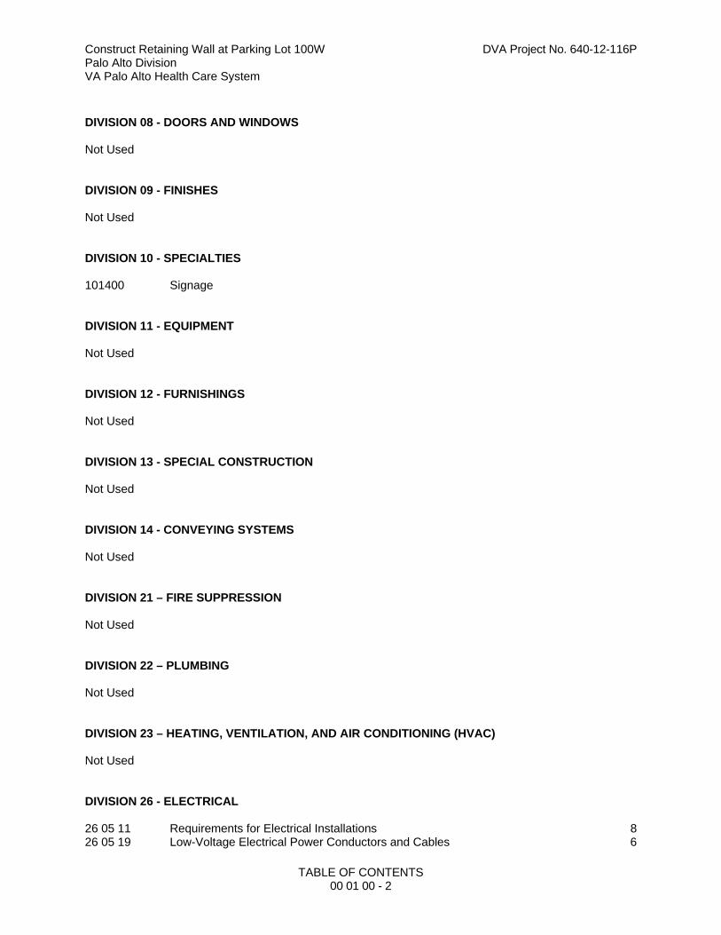
DIVISION 08 - DOORS AND WINDOWS Not Used DIVISION 09 - FINISHES Not Used DIVISION 10 - SPECIALTIES 101400 Signage DIVISION 11 - EQUIPMENT Not Used DIVISION 12 - FURNISHINGS Not Used DIVISION 13 - SPECIAL CONSTRUCTION Not Used DIVISION 14 - CONVEYING SYSTEMS Not Used DIVISION 21 – FIRE SUPPRESSION Not Used DIVISION 22 – PLUMBING Not Used DIVISION 23 – HEATING, VENTILATION, AND AIR CONDITIONING (HVAC) Not Used DIVISION 26 - ELECTRICAL 26 05 11 Requirements for Electrical Installations 8 26 05 19 Low-Voltage Electrical Power Conductors and Cables 6
Construct Retaining Wall at Parking Lot 100W DVA Project No. 640-12-116P Palo Alto Division VA Palo Alto Health Care System
TABLE OF CONTENTS 00 01 00 - 3
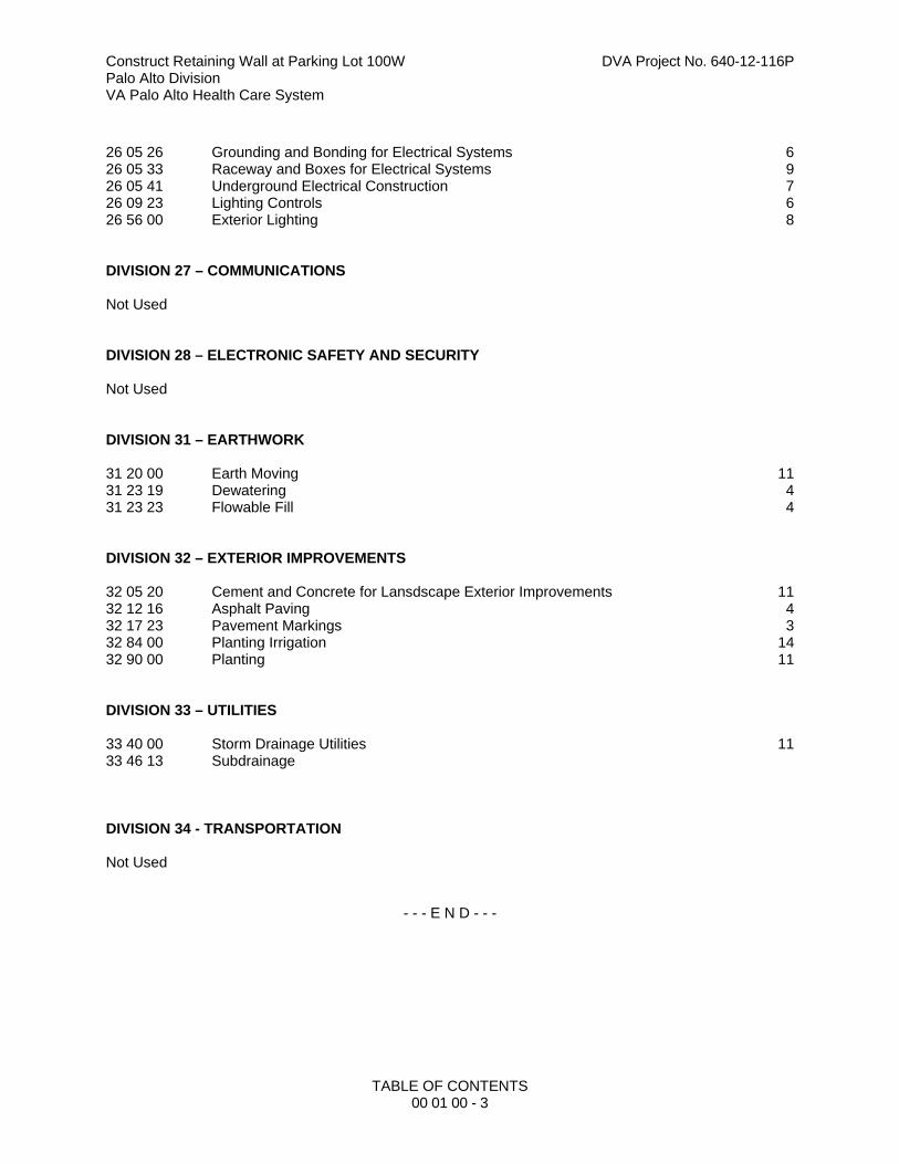
26 05 26 Grounding and Bonding for Electrical Systems 6 26 05 33 Raceway and Boxes for Electrical Systems 9 26 05 41 Underground Electrical Construction 7 26 09 23 Lighting Controls 6 26 56 00 Exterior Lighting 8 DIVISION 27 – COMMUNICATIONS Not Used DIVISION 28 – ELECTRONIC SAFETY AND SECURITY Not Used DIVISION 31 – EARTHWORK 31 20 00 Earth Moving 11 31 23 19 Dewatering 4 31 23 23 Flowable Fill 4 DIVISION 32 – EXTERIOR IMPROVEMENTS 32 05 20 Cement and Concrete for Lansdscape Exterior Improvements 11 32 12 16 Asphalt Paving 4 32 17 23 Pavement Markings 3 32 84 00 Planting Irrigation 14 32 90 00 Planting 11 DIVISION 33 – UTILITIES 33 40 00 Storm Drainage Utilities 11 33 46 13 Subdrainage DIVISION 34 - TRANSPORTATION Not Used
- - - E N D - - -

Construct Retaining Wall at Parking Lot 100W DVA Project No. 640-12-116P Palo Alto Division VA Palo Alto Health Care System
LIST OF DRAWING SHEETS 00 01 15 - 1
SECTION 00 01 15 LIST OF DRAWING SHEETS
The drawings listed below accompanying this specification form a part of the contract. DRAWING NO. TITLE GENERAL
GI 0.0 Cover Sheet GI 1.0 Scope of Work CIVIL C 0.1 General Notes C0.2 Key Map C1.1 Existing Conditions Plan C1.2 Existing Conditions Plan C2.1 Demolition Plan C2.2 Demolition Plan C3.0 Horizontal Control Plan C3.1 Layout Plan C3.2 Layout Plan C4.1 Grading and Utility Plan C4.2 Grading and Utility Plan C 6.1 Erosion Control Plan C 6.2 Erosion Control Plan C 8.1 Details STRUCTURAL S 1.0 Partial Plan and Retaining Wall Details S 2.0 General Notes and Details LANDSCAPE L 1.0 Schedules Notes and Legends L 1.1 Construction Plan L 1.2 Construction Plan L 2.1 Construction Details L 2.2 Construction Details L 3.1 Irrigation Plan L 3.2 Irrigation Plan L 3.3 Irrigation Plan L 4.1 Planting Plan L 4.2 Planting Plan L 4.3 Planting Details ELECTRICAL E 1.1 Construction Plan, Electrical

Construct Retaining Wall at Parking Lot 100W DVA Project No. 640-12-116P Palo Alto Division VA Palo Alto Health Care System
LIST OF DRAWING SHEETS 00 01 15 - 2
SIGNAGE X 0.1 Layout Plan, Elevation
- - - E N D - - -
Construct Retaining Wall at Parking Lot 100W DVA Project No. 640-12-116P Palo Alto Division VA Palo Alto Health Care System
i
SECTION 01 00 00 GENERAL REQUIREMENTS
TABLE OF CONTENTS
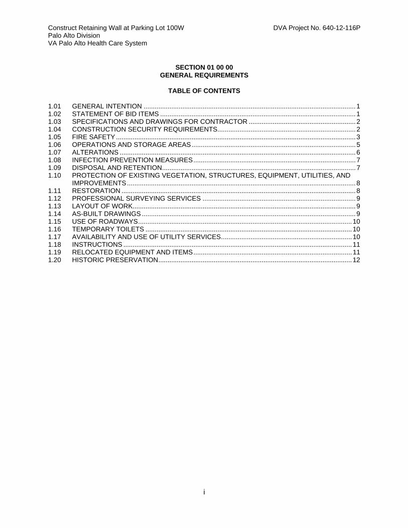
1.01 GENERAL INTENTION ................................................................................................................... 1 1.02 STATEMENT OF BID ITEMS .......................................................................................................... 1 1.03 SPECIFICATIONS AND DRAWINGS FOR CONTRACTOR .......................................................... 2 1.04 CONSTRUCTION SECURITY REQUIREMENTS........................................................................... 2 1.05 FIRE SAFETY .................................................................................................................................. 3 1.06 OPERATIONS AND STORAGE AREAS ......................................................................................... 5 1.07 ALTERATIONS ................................................................................................................................ 6 1.08 INFECTION PREVENTION MEASURES ........................................................................................ 7 1.09 DISPOSAL AND RETENTION ......................................................................................................... 7 1.10 PROTECTION OF EXISTING VEGETATION, STRUCTURES, EQUIPMENT, UTILITIES, AND
IMPROVEMENTS ............................................................................................................................ 8 1.11 RESTORATION ............................................................................................................................... 8 1.12 PROFESSIONAL SURVEYING SERVICES ................................................................................... 9 1.13 LAYOUT OF WORK......................................................................................................................... 9 1.14 AS-BUILT DRAWINGS .................................................................................................................... 9 1.15 USE OF ROADWAYS .................................................................................................................... 10 1.16 TEMPORARY TOILETS ................................................................................................................ 10 1.17 AVAILABILITY AND USE OF UTILITY SERVICES ....................................................................... 10 1.18 INSTRUCTIONS ............................................................................................................................ 11 1.19 RELOCATED EQUIPMENT AND ITEMS ...................................................................................... 11 1.20 HISTORIC PRESERVATION ......................................................................................................... 12
Construct Retaining Wall at Parking Lot 100W DVA Project No. 640-12-116P Palo Alto Division VA Palo Alto Health Care System
GENERAL REQUIREMENTS 01 00 00 - 1
SECTION 01 00 00 GENERAL REQUIREMENTS
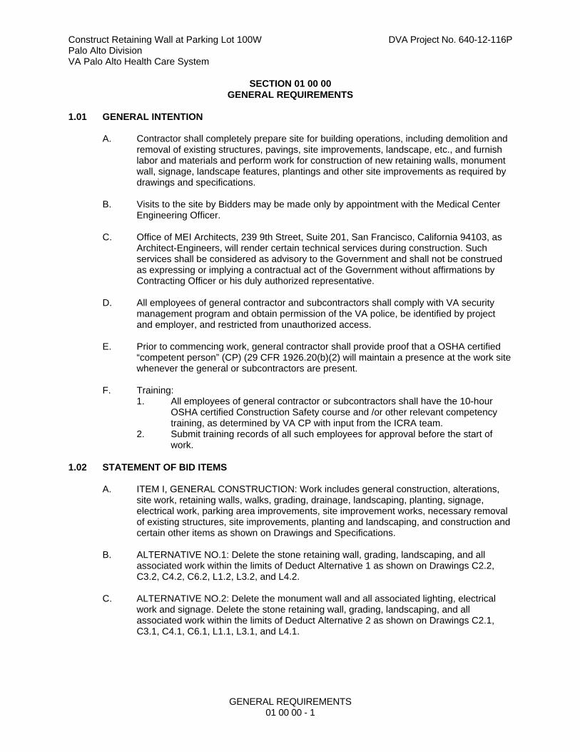
1.01 GENERAL INTENTION
A. Contractor shall completely prepare site for building operations, including demolition and removal of existing structures, pavings, site improvements, landscape, etc., and furnish labor and materials and perform work for construction of new retaining walls, monument wall, signage, landscape features, plantings and other site improvements as required by drawings and specifications.
B. Visits to the site by Bidders may be made only by appointment with the Medical Center
Engineering Officer.
C. Office of MEI Architects, 239 9th Street, Suite 201, San Francisco, California 94103, as Architect-Engineers, will render certain technical services during construction. Such services shall be considered as advisory to the Government and shall not be construed as expressing or implying a contractual act of the Government without affirmations by Contracting Officer or his duly authorized representative.
D. All employees of general contractor and subcontractors shall comply with VA security
management program and obtain permission of the VA police, be identified by project and employer, and restricted from unauthorized access.
E. Prior to commencing work, general contractor shall provide proof that a OSHA certified “competent person” (CP) (29 CFR 1926.20(b)(2) will maintain a presence at the work site whenever the general or subcontractors are present.
F. Training:
1. All employees of general contractor or subcontractors shall have the 10-hour OSHA certified Construction Safety course and /or other relevant competency training, as determined by VA CP with input from the ICRA team.
2. Submit training records of all such employees for approval before the start of work.
1.02 STATEMENT OF BID ITEMS
A. ITEM I, GENERAL CONSTRUCTION: Work includes general construction, alterations, site work, retaining walls, walks, grading, drainage, landscaping, planting, signage, electrical work, parking area improvements, site improvement works, necessary removal of existing structures, site improvements, planting and landscaping, and construction and certain other items as shown on Drawings and Specifications.
B. ALTERNATIVE NO.1: Delete the stone retaining wall, grading, landscaping, and all
associated work within the limits of Deduct Alternative 1 as shown on Drawings C2.2, C3.2, C4.2, C6.2, L1.2, L3.2, and L4.2.
C. ALTERNATIVE NO.2: Delete the monument wall and all associated lighting, electrical
work and signage. Delete the stone retaining wall, grading, landscaping, and all associated work within the limits of Deduct Alternative 2 as shown on Drawings C2.1, C3.1, C4.1, C6.1, L1.1, L3.1, and L4.1.
Construct Retaining Wall at Parking Lot 100W DVA Project No. 640-12-116P Palo Alto Division VA Palo Alto Health Care System
GENERAL REQUIREMENTS 01 00 00 - 2
D. ALTERNATIVE NO.3: In lieu of the specified stainless steel tube handrail, bar supports and stainless steel pipe provide galvanized steel tube handrail, galvanized steel bar supports and galvanized steel pipe for as shown on Drawings L2.1 and L2.2
1.03 852.236-90 RESTRICTION ON SUBMISSION AND USE OF EQUAL PRODUCTS.
A. As prescribed in 836.202(c), the following clause shall be included in the solicitation if it is determined that only one product will meet the Government’s minimum needs and the Department of Veterans Affairs will not allow the submission of ”equal“ products:
RESTRICTION ON SUBMISSION AND USE OF EQUAL PRODUCTS (NOV 1986)
B. The clause applies to the following items:
1. WeatherTRAK ET Pro2 Smart Water Manager
C. Notwithstanding the “Material and Workmanship” clause of this contract, FAR 52.236-5(a), nor any other contractual provision, “equal” products will not be considered by the Department of Veterans Affairs and may not be used.
1.04 SPECIFICATIONS AND DRAWINGS FOR CONTRACTOR
A. Hard copy sets of specifications and drawings will not be furnished to the Contractor.
B. Sets of specifications and drawings may be made by the Contractor, at Contractor's expense, from an electronic copy of the drawings and specifications in PDF format furnished by Issuing Office.
1.05 CONSTRUCTION SECURITY REQUIREMENTS
A. Security Plan: 1. The security plan defines both physical and administrative security procedures
that will remain effective for the entire duration of the project. 2. The General Contractor is responsible for assuring that all sub-contractors
working on the project and their employees also comply with these regulations.
B. Security Procedures: 1. General Contractor’s employees shall not enter the project site without
appropriate badge. They may also be subject to inspection of their personal effects when entering or leaving the project site.
2. For working outside the “regular hours” as defined in the contract, The General Contractor shall give 3 days notice to the Contracting Officer so that security arrangements can be provided for the employees. This notice is separate from any notices required for utility shutdown described later in this section.
3. No photography of VA premises is allowed without written permission of the Contracting Officer.
4. VA reserves the right to close down or shut down the project site and order General Contractor’s employees off the premises in the event of a national emergency. The General Contractor may return to the site only with the written approval of the Contracting Officer.
C. Key Control:
1. The General Contractor shall provide duplicate keys and lock combinations to the Contracting Officer’s Representative (COR) for the purpose of security
Construct Retaining Wall at Parking Lot 100W DVA Project No. 640-12-116P Palo Alto Division VA Palo Alto Health Care System
GENERAL REQUIREMENTS 01 00 00 - 3
inspections of every area of project including tool boxes and parked machines and take any emergency action.
D. Document Control: 1. Before starting any work, the General Contractor/Sub Contractors shall submit
an electronic security memorandum describing the approach to following goals and maintaining confidentiality of “sensitive information”.
2. The General Contractor is responsible for safekeeping of all drawings, project manual and other project information. This information shall be shared only with those with a specific need to accomplish the project.
3. Certain documents, sketches, videos or photographs and drawings may be marked “Law Enforcement Sensitive” or “Sensitive Unclassified”. Secure such information in separate containers and limit the access to only those who will need it for the project. Return the information to the Contracting Officer upon request.
4. These security documents shall not be removed or transmitted from the project site without the written approval of Contracting Officer.
5. All paper waste or electronic media such as CD’s and diskettes shall be shredded and destroyed in a manner acceptable to the VA.
6. Notify Contracting Officer and Site Security Officer immediately when there is a loss or compromise of “sensitive information”.
7. All electronic information shall be stored in specified location following VA standards and procedures using an Engineering Document Management Software (EDMS). a. Security, access and maintenance of all project drawings, both scanned
and electronic shall be performed and tracked through the EDMS system.
b. “Sensitive information” including drawings and other documents may be attached to e-mail provided all VA encryption procedures are followed.
E. Motor Vehicle Restrictions 1. Vehicle authorization request shall be required for any vehicle entering the site
and such request shall be submitted 24 hours before the date and time of access. Access shall be restricted to picking up and dropping off materials and supplies.
2. Separate permits shall be issued for General Contractor and its employees for parking in designated areas only.
1.06 FIRE SAFETY
A. Applicable Publications: Publications listed below form part of this Article to extent referenced. Publications are referenced in text by basic designations only. 1. American Society for Testing and Materials (ASTM):
E84-2009 .......... Surface Burning Characteristics of Building Materials 2. National Fire Protection Association (NFPA):
10-2010 ............ Standard for Portable Fire Extinguishers 30-2008 ............ Flammable and Combustible Liquids Code 51B-2009 .......... Standard for Fire Prevention During Welding, Cutting and Other
Hot Work 70-2011 ............ National Electrical Code 241-2009 .......... Standard for Safeguarding Construction, Alteration, and
Demolition Operations 3. Occupational Safety and Health Administration (OSHA):
29 CFR 1926 .... Safety and Health Regulations for Construction
Construct Retaining Wall at Parking Lot 100W DVA Project No. 640-12-116P Palo Alto Division VA Palo Alto Health Care System
GENERAL REQUIREMENTS 01 00 00 - 4
B. Fire Safety Plan: Establish and maintain a fire protection program in accordance with 29 CFR 1926. Prior to start of work, prepare a plan detailing project-specific fire safety measures, including periodic status reports, and submit to COR and Facility Safety Manager for review for compliance with contract requirements in accordance with Section 01 33 23, SHOP DRAWINGS, PRODUCT DATA AND SAMPLES Prior to any worker for the contractor or subcontractors beginning work, they shall undergo a safety briefing provided by the general contractor’s competent person per OSHA requirements. This briefing shall include information on the construction limits, VAMC safety guidelines, means of egress, break areas, work hours, locations of restrooms, use of VAMC equipment, etc. Documentation shall be provided to the COR that individuals have undergone contractor’s safety briefing.
C. Site and Building Access: Maintain free and unobstructed access to facility emergency services and for fire, police and other emergency response forces in accordance with NFPA 241.
D. Separate temporary facilities, such as trailers, storage sheds, and dumpsters, from existing buildings and new construction by distances in accordance with NFPA 241. For small facilities with less than 6 m (20 feet) exposing overall length, separate by 3m (10 feet).
E. Temporary Heating and Electrical: Install, use and maintain installations in accordance with 29 CFR 1926, NFPA 241 and NFPA 70.
F. Means of Egress: Do not block exiting for occupied buildings, including paths from exits
to roads. Minimize disruptions and coordinate with COR and facility Safety Manager.
G. Egress Routes for Construction Workers: Maintain free and unobstructed egress. Inspect daily. Report findings and corrective actions weekly to COR and facility Safety Manager..
H. Fire Extinguishers: Provide and maintain extinguishers in construction areas and temporary storage areas in accordance with 29 CFR 1926, NFPA 241 and NFPA 10.
I. Flammable and Combustible Liquids: Store, dispense and use liquids in accordance with 29 CFR 1926, NFPA 241 and NFPA 30.
J. Hot Work: Perform and safeguard hot work operations in accordance with NFPA 241 and
NFPA 51B. Coordinate with COR. Obtain permits from facility Safety Manager at least 24 hours in advance. Designate contractor's responsible project-site fire prevention program manager to permit hot work.
K. Fire Hazard Prevention and Safety Inspections: Inspect entire construction areas weekly. Coordinate with, and report findings and corrective actions weekly to COR and facility Safety Manager.
L. Smoking: Smoking is prohibited in and adjacent to construction areas inside existing buildings and additions under construction. In separate and detached buildings under construction, smoking is prohibited except in designated smoking rest areas.
M. Dispose of waste and debris in accordance with NFPA 241. Remove from buildings daily.
N. Perform other construction, alteration and demolition operations in accordance with 29 CFR 1926.

Construct Retaining Wall at Parking Lot 100W DVA Project No. 640-12-116P Palo Alto Division VA Palo Alto Health Care System
GENERAL REQUIREMENTS 01 00 00 - 5
1.07 OPERATIONS AND STORAGE AREAS
A. The Contractor shall confine all operations (including storage of materials) on Government premises to areas authorized or approved by the Contracting Officer. The Contractor shall hold and save the Government, its officers and agents, free and harmless from liability of any nature occasioned by the Contractor's performance.
B. Temporary buildings (e.g., storage sheds, shops, offices) and utilities may be erected by the Contractor only with the approval of the Contracting Officer and shall be built with labor and materials furnished by the Contractor without expense to the Government. The temporary buildings and utilities shall remain the property of the Contractor and shall be removed by the Contractor at its expense upon completion of the work. With the written consent of the Contracting Officer, the buildings and utilities may be abandoned and need not be removed.
C. The Contractor shall, under regulations prescribed by the Contracting Officer, use only established roadways, or use temporary roadways constructed by the Contractor when and as authorized by the Contracting Officer. When materials are transported in prosecuting the work, vehicles shall not be loaded beyond the loading capacity recommended by the manufacturer of the vehicle or prescribed by any Federal, State, or local law or regulation. When it is necessary to cross curbs or sidewalks, the Contractor shall protect them from damage. The Contractor shall repair or pay for the repair of any damaged curbs, sidewalks, or roads.
(FAR 52.236-10)
D. Working space and space available for storing materials shall be as determined by the COR. Relocate staging area as directed by the COR.
E. Workmen are subject to rules of Medical Center applicable to their conduct.
F. Execute work so as to interfere as little as possible with normal functioning of Medical
Center as a whole, including operations of utility services, fire protection systems and any existing equipment, and with work being done by others. 1. Do not store materials and equipment in other than assigned areas. 2. Provide unobstructed access to Medical Center areas required to remain in
operation. 3. Keep roads clear of construction materials, debris, standing construction
equipment and vehicles at all times.
G. Construction Fence: Before construction operations begin, Contractor shall provide a chain link construction fence, 2.1m (seven feet) minimum height, around the construction area as directed by the COR. Provide gates as required for access with necessary hardware, including hasps and padlocks. Fasten fence fabric to terminal posts with tension bands and to line posts and top and bottom rails with tie wires spaced at maximum 375mm (15 inches). Bottom of fences shall extend to 25mm (one inch) above grade. Remove the fence when directed by COR.
H. Utilities Services: Maintain existing utility services for Medical Center at all times. Provide
temporary facilities, labor, materials, equipment, connections, and utilities to assure uninterrupted services. Where necessary to cut existing water, steam, gases, sewer or air pipes, or conduits, wires, cables, etc. of utility services or of fire protection systems and communications systems (including telephone), they shall be cut and capped at suitable places where shown; or, in absence of such indication, where directed by COR. 1. No utility service such as water, gas, steam, sewers or electricity, or fire
protection systems and communications systems may be interrupted without
Construct Retaining Wall at Parking Lot 100W DVA Project No. 640-12-116P Palo Alto Division VA Palo Alto Health Care System
GENERAL REQUIREMENTS 01 00 00 - 6
prior approval of COR. Electrical work shall be accomplished with all affected circuits or equipment de-energized. When an electrical outage cannot be accomplished, work on any energized circuits or equipment shall not commence without the Medical Center Director’s prior knowledge and written approval. Refer to specification Sections 26 05 11, REQUIREMENTS FOR ELECTRICAL INSTALLATIONS for additional requirements.
2. Contractor shall submit a request to interrupt any such services to COR, in writing, 48 hours in advance of proposed interruption. Request shall state reason, date, exact time of, and approximate duration of such interruption.
3. Contractor will be advised (in writing) of approval of request, or of which other date and/or time such interruption will cause least inconvenience to operations of Medical Center. Interruption time approved by Medical Center may occur at other than Contractor's normal working hours.
4. Major interruptions of any system must be requested, in writing, at least 15 calendar days prior to the desired time and shall be performed as directed by the COR.
5. In case of a contract construction emergency, service will be interrupted on approval of COR. Such approval will be confirmed in writing as soon as practical.
6. Whenever it is required that a connection fee be paid to a public utility provider for new permanent service to the construction project, for such items as water, sewer, electricity, gas or steam, payment of such fee shall be the responsibility of the Government and not the Contractor.
I. Abandoned Lines: All service lines such as wires, cables, conduits, ducts, pipes and the like, and their hangers or supports, which are to be abandoned but are not required to be entirely removed, shall be sealed, capped or plugged.
J. To minimize interference of construction activities with flow of Medical Center traffic, comply with the following: 1. Keep roads, walks and entrances to grounds, to parking and to occupied areas
of buildings clear of construction materials, debris and standing construction equipment and vehicles. Wherever excavation for new utility lines cross existing roads, at least one lane must be open to traffic at all times.
2. Method and scheduling of required cutting, altering and removal of existing roads, parking lots, walks and entrances must be approved by the COR.
K. Coordinate the work for this contract with other construction operations as directed by COR. This includes the scheduling of traffic and the use of roadways, as specified in Article, USE OF ROADWAYS.
1.08 ALTERATIONS
A. Survey: Before any work is started, the Contractor shall make a thorough survey with the COR of areas in which alterations occur and areas which are anticipated routes of access, and furnish a report, signed by both, to the Contracting Officer. This report shall list: 1. Existing condition and types of items such as trees, plantings, utility piping,
drainage and accessories, landscaping and other items or site improvements not required to be altered throughout affected areas.
2. Existence and conditions of items such as trees, plantings, utility piping, drainage and accessories, landscaping, etc. required by drawings to be either reused or relocated or both.
3. Shall note any discrepancies between drawings and existing conditions at site.

Construct Retaining Wall at Parking Lot 100W DVA Project No. 640-12-116P Palo Alto Division VA Palo Alto Health Care System
GENERAL REQUIREMENTS 01 00 00 - 7
4. Shall designate areas for working space, materials storage and routes of access to areas within site where alterations occur and which have been agreed upon by Contractor and COR.
B. Any items required by drawings to be either reused or relocated or both, found during this survey to be nonexistent, or in opinion of COR, to be in such condition that their use is impossible or impractical, shall be furnished and/or replaced by Contractor with new items in accordance with specifications which will be furnished by Government. Provided the contract work is changed by reason of this subparagraph B, the contract will be modified accordingly, under provisions of clause entitled "DIFFERING SITE CONDITIONS" (FAR 52.236-2) and "CHANGES" (FAR 52.243-4 and VAAR 852.236-88).
C. Re-Survey: Thirty days before expected partial or final inspection date, the Contractor and COR together shall make a thorough re-survey of the areas of site involved. They shall furnish a report on conditions then existing, of trees, plantings, utility piping, drainage and accessories, landscaping and other items or site improvements as compared with conditions of same as noted in first condition survey report: 1. Re-survey report shall also list any damage caused by Contractor to such items
and other site improvements, despite protection measures; and, will form basis for determining extent of repair work required of Contractor to restore damage caused by Contractor's workmen in executing work of this contract.
D. Protection: Provide the following protective measures: 1. Temporary protection against damage for portions of existing structures and
grounds where work is to be done, materials handled and equipment moved and/or relocated.
1.09 INFECTION PREVENTION MEASURES
A. Implement the requirements of VAMC’s Infection Control Risk Assessment (ICRA) team. ICRA Group may monitor dust in the vicinity of the construction work and require the Contractor to take corrective action immediately if the safe levels are exceeded.
B. Establish and maintain a dust control program as part of the contractor’s infection preventive measures in accordance with the guidelines provided by ICRA Group. Prior to start of work, prepare a plan detailing project-specific dust protection measures, including periodic status reports, and submit to COR and Facility ICRA team for review for compliance with contract requirements in accordance with Section 01 33 23, SHOP DRAWINGS, PRODUCT DATA AND SAMPLES. 1. All personnel involved in the construction or renovation activity shall be educated
and trained in infection prevention measures established by the medical center.
1.10 DISPOSAL AND RETENTION
A. Materials and equipment accruing from work removed and from demolition of buildings or structures, or parts thereof, shall be disposed of as follows: 1. Reserved items which are to remain property of the Government are identified by
attached tags or noted on drawings or in specifications as items to be stored. Items that remain property of the Government shall be removed or dislodged from present locations in such a manner as to prevent damage which would be detrimental to re-installation and reuse. Store such items where directed by COR.
2. Items not reserved shall become property of the Contractor and be removed by Contractor from Medical Center.

Construct Retaining Wall at Parking Lot 100W DVA Project No. 640-12-116P Palo Alto Division VA Palo Alto Health Care System
GENERAL REQUIREMENTS 01 00 00 - 8
3. Items of portable equipment and furnishings located in areas in which work is to be done under this contract shall remain the property of the Government. When areas are vacated by the Department of Veterans Affairs during the alteration period, such items which are NOT required by drawings and specifications to be either relocated or reused will be removed by the Government in advance of work to avoid interfering with Contractor's operation.
1.11 PROTECTION OF EXISTING VEGETATION, STRUCTURES, EQUIPMENT, UTILITIES, AND
IMPROVEMENTS
A. The Contractor shall preserve and protect all structures, equipment, and vegetation (such as trees, shrubs, and grass) on or adjacent to the work site, which are not to be removed and which do not unreasonably interfere with the work required under this contract. The Contractor shall only remove trees when specifically authorized to do so, and shall avoid damaging vegetation that will remain in place. If any limbs or branches of trees are broken during contract performance, or by the careless operation of equipment, or by workmen, the Contractor shall trim those limbs or branches with a clean cut and paint the cut with a tree-pruning compound as directed by the Contracting Officer.
B. The Contractor shall protect from damage all existing improvements and utilities at or near the work site and on adjacent property of a third party, the locations of which are made known to or should be known by the Contractor. The Contractor shall repair any damage to those facilities, including those that are the property of a third party, resulting from failure to comply with the requirements of this contract or failure to exercise reasonable care in performing the work. If the Contractor fails or refuses to repair the damage promptly, the Contracting Officer may have the necessary work performed and charge the cost to the Contractor.
(FAR 52.236-9)
C. Refer to Section 01 57 19, TEMPORARY ENVIRONMENTAL CONTROLS, for additional requirements on protecting vegetation, soils and the environment. Refer to Articles, "Alterations", "Restoration", and "Operations and Storage Areas" for additional instructions concerning repair of damage to structures and site improvements.
1.12 RESTORATION
A. Remove, cut, alter, replace, patch and repair existing work as necessary to install new work. Except as otherwise shown or specified, do not cut, alter or remove any structural work, and do not disturb any ducts, plumbing, steam, gas, or electric work without approval of the COR. Existing work to be altered or extended and that is found to be defective in any way, shall be reported to the COR before it is disturbed. Materials and workmanship used in restoring work shall conform in type and quality to that of original existing construction, except as otherwise shown or specified.
B. Upon completion of contract, deliver work complete and undamaged. Existing work (walls, ceilings, partitions, floors, mechanical and electrical work, lawns, plantings, paving, roads, walks, site improvements, etc.) disturbed or removed as a result of performing required new work, shall be patched, repaired, reinstalled, or replaced with new work, and refinished and left in as good condition as existed before commencing work.
C. At Contractor's own expense, Contractor shall immediately restore to service and repair any damage caused by Contractor's workmen to existing piping and conduits, wires, cables, etc., of utility services or of fire protection systems and communications systems
Construct Retaining Wall at Parking Lot 100W DVA Project No. 640-12-116P Palo Alto Division VA Palo Alto Health Care System
GENERAL REQUIREMENTS 01 00 00 - 9
(including telephone) which are indicated on drawings and which are not scheduled for discontinuance or abandonment.
D. Expense of repairs to such utilities and systems not shown on drawings or locations of which are unknown will be covered by adjustment to contract time and price in accordance with clause entitled "CHANGES" (FAR 52.243-4 and VAAR 852.236-88) and "DIFFERING SITE CONDITIONS" (FAR 52.236-2).
1.13 PROFESSIONAL SURVEYING SERVICES
A. A registered professional land surveyor or registered civil engineer whose services are retained and paid for by the Contractor shall perform services specified herein and in other specification sections. The Contractor shall certify that the land surveyor or civil engineer is not one who is a regular employee of the Contractor, and that the land surveyor or civil engineer has no financial interest in this contract.
1.14 LAYOUT OF WORK
A. The Contractor shall lay out the work from Government established base lines and bench marks, indicated on the drawings, and shall be responsible for all measurements in connection with the layout. The Contractor shall furnish, at Contractor's own expense, all stakes, templates, platforms, equipment, tools, materials, and labor required to lay out any part of the work. The Contractor shall be responsible for executing the work to the lines and grades that may be established or indicated by the Contracting Officer. The Contractor shall also be responsible for maintaining and preserving all stakes and other marks established by the Contracting Officer until authorized to remove them. If such marks are destroyed by the Contractor or through Contractor's negligence before their removal is authorized, the Contracting Officer may replace them and deduct the expense of the replacement from any amounts due or to become due to the Contractor.
(FAR 52.236-17) B. Establish and plainly mark lines and grades that are reasonably necessary to properly
assure that location, orientation, and elevations established for walls, roads, parking lots, are in accordance with lines and elevations shown on contract drawings.
C. Whenever changes from contract drawings are made in line or grading requiring certificates, record such changes on a reproducible drawing bearing the registered land surveyor or registered civil engineer seal, and forward these drawings upon completion of work to COR.
D. The Contractor shall perform the surveying and layout work of this and other articles and specifications in accordance with the provisions of Article "Professional Surveying Services".
1.15 AS-BUILT DRAWINGS
A. The contractor shall maintain two full size sets of as-built drawings which will be kept current during construction of the project, to include all contract changes, modifications and clarifications.
B. All variations shall be shown in the same general detail as used in the contract drawings. To insure compliance, as-built drawings shall be made available for the COR's review, as often as requested.

Construct Retaining Wall at Parking Lot 100W DVA Project No. 640-12-116P Palo Alto Division VA Palo Alto Health Care System
GENERAL REQUIREMENTS 01 00 00 - 10
C. Contractor shall deliver two approved completed sets of as-built drawings to the COR within 15 calendar days after each completed phase and after the acceptance of the project by the COR.
D. Paragraphs A, B, & C shall also apply to all shop drawings.
1.16 USE OF ROADWAYS
A. For hauling, use only established public roads and roads on Medical Center property and, when authorized by the COR, such temporary roads which are necessary in the performance of contract work. Temporary roads shall be constructed by the Contractor at Contractor's expense. When necessary to cross curbing, sidewalks, or similar construction, they must be protected by well-constructed bridges.
B. When new permanent roads are to be a part of this contract, Contractor may construct them immediately for use to facilitate building operations. These roads may be used by all who have business thereon within zone of building operations.
1.17 TEMPORARY TOILETS
A. Provide where directed, (for use of all Contractor's workmen) ample temporary sanitary
toilet accommodations with suitable sewer and water connections; or, when approved by COR, provide suitable dry closets where directed. Keep such places clean and free from flies, and all connections and appliances connected therewith are to be removed prior to completion of contract, and premises left perfectly clean.
1.18 AVAILABILITY AND USE OF UTILITY SERVICES
A. The Government shall make all reasonably required amounts of utilities available to the Contractor from existing outlets and supplies, as specified in the contract. The amount to be paid by the Contractor for chargeable electrical services shall be the prevailing rates charged to the Government. The Contractor shall carefully conserve any utilities furnished without charge.
B. The Contractor, at Contractor's expense and in a workmanlike manner satisfactory to the Contracting Officer, shall install and maintain all necessary temporary connections and distribution lines, and all meters required to measure the amount of electricity used for the purpose of determining charges. Before final acceptance of the work by the Government, the Contractor shall remove all the temporary connections, distribution lines, meters, and associated paraphernalia.
C. Contractor shall install meters at Contractor's expense and furnish the Medical Center a monthly record of the Contractor's usage of electricity as hereinafter specified.
D. Electricity (for Construction and Testing): Furnish all temporary electric services.
1. Obtain electricity by connecting to the Medical Center electrical distribution system. The Contractor shall meter and pay for electricity required for electric cranes and hoisting devices, electrical welding devices and any electrical heating devices providing temporary heat. Electricity for all other uses is available at no cost to the Contractor.
E. Water (for Construction and Testing): Furnish temporary water service. 1. Obtain water by connecting to the Medical Center water distribution system.
Provide reduced pressure backflow preventer at each connection. Water is available at no cost to the Contractor.
Construct Retaining Wall at Parking Lot 100W DVA Project No. 640-12-116P Palo Alto Division VA Palo Alto Health Care System
GENERAL REQUIREMENTS 01 00 00 - 11
2. Maintain connections, pipe, fittings and fixtures and conserve water-use so none is wasted. Failure to stop leakage or other wastes will be cause for revocation (at COR's discretion) of use of water from Medical Center's system.
1.19 INSTRUCTIONS
A. Contractor shall furnish Maintenance and Operating manuals and verbal instructions when required by the various sections of the specifications and as hereinafter specified.
B. Manuals: Maintenance and operating manuals (four copies each) for each separate piece of equipment shall be delivered to the COR coincidental with the delivery of the equipment to the job site. Manuals shall be complete, detailed guides for the maintenance and operation of equipment. They shall include complete information necessary for starting, adjusting, maintaining in continuous operation for long periods of time and dismantling and reassembling of the complete units and sub-assembly components. Manuals shall include an index covering all component parts clearly cross-referenced to diagrams and illustrations. Illustrations shall include "exploded" views showing and identifying each separate item. Emphasis shall be placed on the use of special tools and instruments. The function of each piece of equipment, component, accessory and control shall be clearly and thoroughly explained. All necessary precautions for the operation of the equipment and the reason for each precaution shall be clearly set forth. Manuals must reference the exact model, style and size of the piece of equipment and system being furnished. Manuals referencing equipment similar to but of a different model, style, and size than that furnished will not be accepted.
C. Instructions: Contractor shall provide qualified, factory-trained manufacturers' representatives to give detailed instructions to assigned Department of Veterans Affairs personnel in the operation and complete maintenance for each piece of equipment. All such training will be at the job site. These requirements are more specifically detailed in the various technical sections. Instructions for different items of equipment that are component parts of a complete system, shall be given in an integrated, progressive manner. All instructors for every piece of component equipment in a system shall be available until instructions for all items included in the system have been completed. This is to assure proper instruction in the operation of inter-related systems. All instruction periods shall be at such times as scheduled by the COR and shall be considered concluded only when the COR is satisfied in regard to complete and thorough coverage. The Department of Veterans Affairs reserves the right to request the removal of, and substitution for, any instructor who, in the opinion of the COR, does not demonstrate sufficient qualifications in accordance with requirements for instructors above.
1.20 RELOCATED EQUIPMENT AND ITEMS
A. Contractor shall disconnect, dismantle as necessary, remove and reinstall in new location, all existing equipment indicated by symbol "R" or otherwise shown to be relocated by the Contractor.
B. Perform relocation of such equipment or items at such times and in such a manner as directed by the COR.
C. Suitably cap existing service lines, such as steam, condensate return, water, drain, gas, air, vacuum and/or electrical, whenever such lines are disconnected from equipment to be relocated. Remove abandoned lines in finished areas and cap as specified herein before under paragraph "Abandoned Lines".
Construct Retaining Wall at Parking Lot 100W DVA Project No. 640-12-116P Palo Alto Division VA Palo Alto Health Care System
GENERAL REQUIREMENTS 01 00 00 - 12
D. Provide all mechanical and electrical service connections, fittings, fastenings and any other materials necessary for assembly and installation of relocated equipment; and leave such equipment in proper operating condition.
E. All service lines such as noted above for relocated equipment shall be in place at point of
relocation ready for use before any existing equipment is disconnected. Make relocated existing equipment ready for operation or use immediately after reinstallation.
1.21 HISTORIC PRESERVATION
A. Where the Contractor or any of the Contractor's employees, prior to, or during the construction work, are advised of or discover any possible archeological, historical and/or cultural resources, the Contractor shall immediately notify the COR verbally, and then with a written follow up.
1.22 ADDITIONAL REQUIREMENTS FOR WORK AT PALO ALTO HEALTH CARE SYSTEM
A. Refer to attached “VAPAHCS Rules of the Station”, dated 04/02/2012
- - - E N D - - -

Rev 04/02/12

Rev 04/02/12
RULES OF THE STATION
VETERANS AFFAIRS PALO ALTO HEALTH CARE SYSTEM
The guidelines published in this issue are for the use and convenience of construction and maintenance contractors, vendors and others performing contract work at all Divisions of the VA Palo Alto Health Care System. INDEX A. Contract Work Hours B. Utilities C. Protective Clothing/Equipment D. Telephones E. Elevators/Corridors F. Toilets G. Parking/Traffic H. Deliveries I. Loading/Unloading J. Federal Police K. Locked Areas L. Operations and Storage Areas M. Construction Waste and Debris N. Recreational Facilities O. Disposal of Hazardous Materials P. Wash Down Q. Removal of Government Property R. Sexual Harassment S. Drugs and Alcohol T. Firearms and Explosive Devices U. Smoking V. Lost and Found W. Smoke Barrier Partitions X. Welding/Burning Y. Low Voltage Cable Installation Z. Occupational Health and Safety AA. Injury Accidents BB. Damage to Government Property CC. Dust and Fume Control DD. Noise EE. Roads and Walks FF. Fire Safety Precautions A. CONTRACT WORK HOURS. All work on the contract shall be performed
between 8:00 am and 4:30pm Monday through Friday, excluding National Holidays, unless approved in writing by the Contracting Officer. Contractors

Rev 04/02/12
may request, in writing, approval to work other hours or weekends. Except for emergencies, the contract person should receive such requests two weeks before the scheduled work. When possible, Contractors will submit emergency requests at least two days before the scheduled work.
B. UTILITIES. No utility service such as water, gas, medical air and gas, steam, sewer, electric, fire protection or communication shall be interrupted without prior approval of the contact person. This includes those interruptions required by the contract. Construction contracts include provisions for maintaining utility systems or providing temporary facilities. Utility shutdowns shall be done on weekends. Requests for utility shutdowns shall reach the contact person at least 30 days before the scheduled work. Any EMERGENCY REQUIRING AN IMMEDIATE SHUTDOWN WILL BE REPORTED IMMEDIATELY to the contact person. The contact person will in turn immediately notify the Engineering Office and the appropriate Chief, Facilities and Operations. The Contractor will prepare and forward to the Chief, Engineering Service, a written report of the situation, why it happened, a schedule of any further corrective work needed, and what, if any steps are being taken to prevent a recurrence.
C. INTERIM LIFE SAFETY MEASURES. If a Fire Alarm system is out of service for more than 4 hours, or if a Sprinkler system is out of service for more than 4 hours, then this shall require the contractor to implement Interim Life Safety Measures in accordance with the latest issue of the VA Palo Alto Health Care System Memorandum SAFE 07-23.
D. PROTECTIVE CLOTHING/EQUIPMENT. All workers will wear and/or use protective clothing and gear when required. This includes hard hats, goggles, protective shoes, gloves, masks or breathing apparatus, etc. The Contractor shall provide and protective equipment that may be required.
E. TELEPHONES. Contractors may provide their own telephone, or pay telephones are available at may locations throughout the VA Palo Alto Health Care System for public use including contractors and the contract workers. Government telephones will not be used for private business or personal calls. Contractors or their workers may use the Government telephones to call/page the contact person, the Engineering Service office, or when authorized by the contact person - to call their office concerning contract matters. Telephone calls for contract workers will not be accepted by the Health Care System.
F. ELEVATORS/CORRIDORS. Contractors and workers may use corridors and elevators for travel to and from the job sites when in proper attire (shirt and shoes required) provided they don’t track mud, wet cement or any form of “dirt” into the buildings. The contact person will assign specific routes, times and elevators to use for transportation of materials and equipment. The Contractor will clean-up any mess caused by their workmen. Smoking is prohibited in elevators and corridors. Elevators will not be used during an emergency.
G. TOILETS. The Contractor is to provide their own toilet facilities, however, the contact person will advise the Contractor which toilet facilities (if available)
Rev 04/02/12
may be used by the Contractor’s workmen. The Contractor will ensure that the facilities are kept clean and will be responsible for any damage done by the Contractor’s workers.
H. PARKING/TRAFFIC. Specific parking areas may be assigned for workers on larger construction projects. Workers on smaller construction or maintenance contracts may use that is away from buildings if no parking area is designated. Contractors, including maintenance contractors and workers are specifically prohibited from parking in those spaces reserved for Engineering Vehicles or lawn areas. Further, the Contractor is not to “back in” the space.
I. DELIVERIES. The contact person will assign routes for the delivery of materials and supplies to the job site. The Contractor or construction traffic will not block any Health Care System road or street, walk or building egress without requesting approval in a timely manner.
J. LOADING/UNLOADING. Building loading docks and landings may be used to load or unload construction materials when approved by the contact person. However, any vehicle left unattended for more than a few minutes may be cited by the Health Care System Police. Some areas may be reserved for Health Care System operations only during certain hours.
K. FEDERAL POLICE. The Health Care System Police are Federal Police Officers with full authority to make arrests, investigate crime, and to issue citations. Citations issued for driving, parking violations or other offenses usually require an appearance in the Federal District Court and/or payment of a fine. FOR THE SAFETY OF PATIENTS speed limits, other driving and parking codes are strictly enforced.
L. LOCKED AREAS. The Contractor is to coordinate access to locked areas with the contact person, including obtaining keys required for access to work sites. All buildings at the Health Care System are locked during other than normal work hours. When the Contractor has approval to work other than normal work hours, he will need to make arrangements for his workers to have access to job sites.
M. OPERATIONS AND STORAGE AREAS will be confined to areas designated by the contract or approved in writing by the contact person or the Contacting Officer. The Government will not be responsible for any tools, equipment or materials left or stored on Government facilities, unless exceptions are provided in the contract.
N. CONSTRUCTION WASTE AND DEBRIS will not be disposed of on station or in Health Care System trash containers or dumpsters. The Contractor may provide his own bin or dumpster, however, the use and location of such must be approved in writing by the contract person. Construction waste and debris will not be accumulated in corridors or other building areas where it might cause a fire or safety hazard.
O. RECREATIONAL FACILITIES such as swimming pools, gym, tennis courts, etc. Are not to be used by Contractors or Contractor’s workers. Contractors and workers, in proper attire, are permitted to use the canteen for breaks and lunch and to purchase incidentals in the Canteen Store.
Rev 04/02/12
P. DISPOSAL OF HAZARDOUS MATERIALS. Several buildings at the VAPAHCS contain asbestos containing materials (ACM). Some typical types of materials found to contain ACMs are pipe insulation, transit wall panels, floor tile, linoleum backing, floor/roof mastics and others. Contractors are required to communicate this information to all of their employees and subcontractors that will be working at any of the VAPAHCS sites, and failure to do so could result in OSHA citation(s). Contractors are also required to alert the VAPAHCS immediately in the event any known or suspected ACM is accidentally disturbed or will need to be disturbed before proceeding with work. If not indicated in the contract drawings, known locations of ACMs can be determined from the current VAPAHCS asbestos survey. Disposal of any hazardous or potentially hazardous materials in sanitary or storm sewer systems or on Health Care System grounds is strictly prohibited. Hazardous materials, such as asbestos materials, used cleaning solutions and other harmful chemicals shall be disposed of in accordance with State and/or local laws and regulations. In case of an accidental spill of hazardous materials, the contractor is expected to take immediate action to contain the spill and at the same time notify the C.O.T.R./Contracting Officer of the spill. Action should being taken to mitigate the situation until you receive direction from the VAPAHCS Quality Management personnel.
Q. WASH DOWN. Washing leftover cement, plaster, paint, oil or grease, solvents, etc. Into any drains and the washing down of cement trucks or other delivery vehicles is strictly prohibited. REPORT ANY ACIDENTAL SPILLS THAT MAY RUN INTO STORN DRAINS IMMEDIATELY TO THE ENGINEERING SERVICE AT EXTENSION 62468. Even accidental spills, particularly those not immediately controlled or contained, may result in legal action by local or state authorities against the responsible parties.
R. REMOVAL OF GOVERNMENT PROPERTY, including empty boxes, crates, wood, etc. is prohibited, except approved by the Chief, Supply Service. Contractors or vendors taking Government equipment off station for repairs will notify the contact person of such action. In most cases, a receipt will be required.
S. SEXUAL HARASSMENT is strictly prohibited. This includes deliberate or unsolicited verbal comments or gestures of a sexual nature, unwelcome sexual advances, requests for sexual favors and/or other unwelcome verbal or physical conduct of a sexual nature.
T. DRUGS AND ALCOHOL. Possession or use of non-prescription drugs or alcohol, including beer and wine, on the Health Care System grounds is strictly prohibited.
U. FIREARMS AND EXPLOSIVES. Possession of firearms, ammunitions, explosive devices and any hand held item that may be considered an offensive weapon is strictly prohibited. This includes carrying such items in vehicles.
V. SMOKING POLICY. Smoking is prohibited in all Health Care System Buildings particularly in corridors, elevators, offices and patient areas, except in designated areas.

Rev 04/02/12
W. LOST AND FOUND. Any article or money found on the premises should be delivered immediately to the contact person or the Health Care System Police for safekeeping. Anyone losing an article or money should contact the Health Care System Police to determine if it has been turned in.
X. SMOKE/FIRE BARRIER PENETRATIONS. Any penetrations to smoke or fire barrier walls, ceiling or floor slabs shall be properly sealed immediately. We recommend Hilti Fire Stop 601 or 635 for walls and ceilings and Hilti Fire Stop 657 for floor penetrations.
Y. WELDING AND OR BURNING: Any person planning welding, cutting metal studs or other such burning operations will obtain a burning permit from the Occupational Health and Safety Office, extension 65894. Welding and/or burning operations are allowed only during normal working hours.
Z. LOW VOLTAGE CABLE INSTALLATION: The contractor shall install low voltage cable in raceways only after scheduling the work with the contact person. Whenever feasible, low voltage cables to be in the ceiling will be installed before the ceiling tile is installed.
AA. OCCUPATIONAL HEALTH AND SAFETY: Contractors and their employees are expected to comply with and are subject to applicable OSHA and CAL-OSHA regulations as at any construction site.
BB. INJURY ACCIDENTS: The Health Care System does not have the equipment, facilities, or personnel trained to handler serious injuries. Call 911 from a pay phone (or use an outside line) for emergency medical assistance and notify the contact person and the Health Care System Police.
CC. DAMAGE TO GOVERNMENT PROPERTY caused by the Contractor or his workmen, whether accidental or incidental to the work, shall be corrected immediately at he Contractor’s expense. This includes damage to lawns, shrubbery, irrigation systems, curbs, etc. Caused by construction vehicles/traffic and other operations.
DD. DUST AND FUME CONTROL will be exercised on all construction operations. Workers will be careful not to operate any vehicles, gas or diesel engines, or to perform any fume or dust generating process near a building intake system.
EE. NOISE will be held to a minimum at all times. Jack-hammering, core drilling and other noisy or disturbing operations may have to be rescheduled (or accomplished after hours) to avoid interfering with surgery or other programs. OSHA standards related to decibels are a requirement in any event.
FF. ROADS & WALKS. Any debris dropped along egress from the station will be cleaned up immediately. Mud and dirt on roads and walks will be cleaned up as soon as the construction operation is complete or at the end of each day.
GG. FIRE SAFETY PRECAUTIONS Contractors are expected to comply with all fire safety precautions. In the event of a fire or during regular fire drill, the contractor must vacate the construction site within the zone affected.
- - - E N D - - -

Construct Retaining Wall at Parking Lot 100W DVA Project No. 640-12-116P Palo Alto Division VA Palo Alto Health Care System
PROJECT SCHEDULES 01 32 16 - 1
SECTION 01 32 16 PROJECT SCHEDULES
PART 1 – GENERAL
1.01 DESCRIPTION
A. The Contractor shall develop a Critical Path Method (CPM) plan and schedule
demonstrating fulfillment of the contract requirements (Project Schedule), and shall keep the Project Schedule up-to-date in accordance with the requirements of this section and shall utilize the plan for scheduling, coordinating and monitoring work under this contract (including all activities of subcontractors, equipment vendors and suppliers). Conventional Critical Path Method (CPM) technique shall be utilized to satisfy both time and cost applications.
1.02 CONTRACTOR'S REPRESENTATIVE
A. The Contractor shall designate an authorized representative responsible for the Project
Schedule including preparation, review and progress reporting with and to the Contracting Officer's Representative (COR).
B. The Contractor's representative shall have direct project control and complete authority to
act on behalf of the Contractor in fulfilling the requirements of this specification section.
C. The Contractor’s representative shall have the option of developing the project schedule within their organization or to engage the services of an outside consultant. If an outside scheduling consultant is utilized, Section 1.3 of this specification will apply.
1.03 CONTRACTOR'S CONSULTANT
A. The Contractor shall submit a qualification proposal to the COR, within 10 days of bid
acceptance. The qualification proposal shall include: 1. The name and address of the proposed consultant. 2. Information to show that the proposed consultant has the qualifications to meet
the requirements specified in the preceding paragraph. 3. A representative sample of prior construction projects, which the proposed
consultant has performed complete project scheduling services. These representative samples shall be of similar size and scope.
B. The Contracting Officer has the right to approve or disapprove the proposed consultant,
and will notify the Contractor of the VA decision within seven calendar days from receipt of the qualification proposal. In case of disapproval, the Contractor shall resubmit another consultant within 10 calendar days for renewed consideration. The Contractor shall have their scheduling consultant approved prior to submitting any schedule for approval.
1.04 COMPUTER PRODUCED SCHEDULES
A. The contractor shall provide monthly, to the Department of Veterans Affairs (VA), all
computer-produced time/cost schedules and reports generated from monthly project updates. This monthly computer service will include: three copies of up to five different reports (inclusive of all pages) available within the user defined reports of the scheduling software approved by the Contracting Officer; a hard copy listing of all project schedule changes, and associated data, made at the update and an electronic file of this data; and the resulting monthly updated schedule in PDM format. These must be submitted with and substantively support the contractor’s monthly payment request and the signed look
Construct Retaining Wall at Parking Lot 100W DVA Project No. 640-12-116P Palo Alto Division VA Palo Alto Health Care System
PROJECT SCHEDULES 01 32 16 - 2
ahead report. The COR shall identify the five different report formats that the contractor shall provide.
B. The contractor shall be responsible for the correctness and timeliness of the computer-
produced reports. The Contractor shall also responsible for the accurate and timely submittal of the updated project schedule and all CPM data necessary to produce the computer reports and payment request that is specified.
C. The VA will report errors in computer-produced reports to the Contractor’s representative
within ten calendar days from receipt of reports. The Contractor shall reprocess the computer-produced reports and associated diskette(s), when requested by the Contracting Officer’s representative, to correct errors which affect the payment and schedule for the project.
1.05 THE COMPLETE PROJECT SCHEDULE SUBMITTAL
A. Within 45 calendar days after receipt of Notice to Proceed, the Contractor shall submit for
the Contracting Officer's review; three blue line copies of the interim schedule on sheets of paper 765 x 1070 mm (30 x 42 inches) and an electronic file in the previously approved CPM schedule program. The submittal shall also include three copies of a computer-produced activity/event ID schedule showing project duration; phase completion dates; and other data, including event cost. Each activity/event on the computer-produced schedule shall contain as a minimum, but not limited to, activity/event ID, activity/event description, duration, budget amount, early start date, early finish date, late start date, late finish date and total float. Work activity/event relationships shall be restricted to finish-to-start or start-to-start without lead or lag constraints. Activity/event date constraints, not required by the contract, will not be accepted unless submitted to and approved by the Contracting Officer. The contractor shall make a separate written detailed request to the Contracting Officer identifying these date constraints and secure the Contracting Officer’s written approval before incorporating them into the network diagram. The Contracting Officer’s separate approval of the Project Schedule shall not excuse the contractor of this requirement. Logic events (non-work) will be permitted where necessary to reflect proper logic among work events, but must have zero duration. The complete working schedule shall reflect the Contractor's approach to scheduling the complete project. The final Project Schedule in its original form shall contain no contract changes or delays which may have been incurred during the final network diagram development period and shall reflect the entire contract duration as defined in the bid documents. These changes/delays shall be entered at the first update after the final Project Schedule has been approved. The Contractor should provide their requests for time and supporting time extension analysis for contract time as a result of contract changes/delays, after this update, and in accordance with Article, ADJUSTMENT OF CONTRACT COMPLETION.
B. Within 30 calendar days after receipt of the complete project interim Project Schedule
and the complete final Project Schedule, the Contracting Officer or his representative, will do one or both of the following: 1. Notify the Contractor concerning his actions, opinions, and objections. 2. A meeting with the Contractor at or near the job site for joint review, correction or
adjustment of the proposed plan will be scheduled if required. Within 14 calendar days after the joint review, the Contractor shall revise and shall submit three blue line copies of the revised Project Schedule, three copies of the revised computer-produced activity/event ID schedule and a revised electronic file as specified by the Contracting Officer. The revised submission will be reviewed by the Contracting Officer and, if found to be as previously agreed upon, will be approved.
Construct Retaining Wall at Parking Lot 100W DVA Project No. 640-12-116P Palo Alto Division VA Palo Alto Health Care System
PROJECT SCHEDULES 01 32 16 - 3
C. The approved baseline schedule and the computer-produced schedule(s) generated
there from shall constitute the approved baseline schedule until subsequently revised in accordance with the requirements of this section.
D. The Complete Project Schedule shall contain approximately 1000 work activities/events.
1.06 WORK ACTIVITY/EVENT COST DATA
A. The Contractor shall cost load all work activities/events except procurement activities.
The cumulative amount of all cost loaded work activities/events (including alternates) shall equal the total contract price. Prorate overhead, profit and general conditions on all work activities/events for the entire project length. The contractor shall generate from this information cash flow curves indicating graphically the total percentage of work activity/event dollar value scheduled to be in place on early finish, late finish. These cash flow curves will be used by the Contracting Officer to assist him in determining approval or disapproval of the cost loading. Negative work activity/event cost data will not be acceptable, except on VA issued contract changes.
B. The Contractor shall cost load work activities/events for guarantee period services, test,
balance and adjust various systems in accordance with the provisions in Article, FAR 52.232 – 5 (PAYMENT UNDER FIXED-PRICE CONSTRUCTION CONTRACTS) and VAAR 852.236 – 83 (PAYMENT UNDER FIXED-PRICE CONSTRUCTION CONTRACTS).
C. In accordance with FAR 52.236 – 1 (PERFORMANCE OF WORK BY THE
CONTRACTOR) and VAAR 852.236 – 72 (PERFORMANCE OF WORK BY THE CONTRACTOR), the Contractor shall submit, simultaneously with the cost per work activity/event of the construction schedule required by this Section, a responsibility code for all activities/events of the project for which the Contractor's forces will perform the work.
D. The Contractor shall cost load work activities/events for all BID ITEMS including
ASBESTOS ABATEMENT. The sum of each BID ITEM work shall equal the value of the bid item in the Contractors' bid.
1.07 PROJECT SCHEDULE REQUIREMENTS
A. Show on the project schedule the sequence of work activities/events required for
complete performance of all items of work. The Contractor Shall: 1. Show activities/events as:
a. Contractor's time required for submittal of shop drawings, templates, fabrication, delivery and similar pre-construction work.
b. Contracting Officer's and Architect-Engineer's review and approval of shop drawings, equipment schedules, samples, template, or similar items.
c. Interruption of VA Facilities utilities, delivery of Government furnished equipment, and rough-in drawings, project phasing and any other specification requirements.
d. Test, balance and adjust various systems and pieces of equipment, maintenance and operation manuals, instructions and preventive maintenance tasks.
e. VA inspection and acceptance activity/event with a minimum duration of five work days at the end of each phase and immediately preceding any VA move activity/event required by the contract phasing for that phase.

Construct Retaining Wall at Parking Lot 100W DVA Project No. 640-12-116P Palo Alto Division VA Palo Alto Health Care System
PROJECT SCHEDULES 01 32 16 - 4
2. Show not only the activities/events for actual construction work for each trade category of the project, but also trade relationships to indicate the movement of trades from one area, floor, or building, to another area, floor, or building, for at least five trades who are performing major work under this contract.
3. Break up the work into activities/events of a duration no longer than 20 work days each or one reporting period, except as to non-construction activities/events (i.e., procurement of materials, delivery of equipment, concrete and asphalt curing) and any other activities/events for which the COR may approve the showing of a longer duration. The duration for VA approval of any required submittal, shop drawing, or other submittals will not be less than 20 work days.
4. Describe work activities/events clearly, so the work is readily identifiable for assessment of completion. Activities/events labeled "start," "continue," or "completion," are not specific and will not be allowed. Lead and lag time activities will not be acceptable.
5. The schedule shall be generally numbered in such a way to reflect either discipline, phase or location of the work.
B. The Contractor shall submit the following supporting data in addition to the project
schedule: 1. The appropriate project calendar including working days and holidays. 2. The planned number of shifts per day. 3. The number of hours per shift.
Failure of the Contractor to include this data shall delay the review of the submittal until the Contracting Officer is in receipt of the missing data.
C. To the extent that the Project Schedule or any revised Project Schedule shows anything
not jointly agreed upon, it shall not be deemed to have been approved by the COR. Failure to include any element of work required for the performance of this contract shall not excuse the Contractor from completing all work required within any applicable completion date of each phase regardless of the COR’s approval of the Project Schedule.
D. Compact Disk Requirements and CPM Activity/Event Record Specifications: Submit to
the VA an electronic file(s) containing one file of the data required to produce a schedule, reflecting all the activities/events of the complete project schedule being submitted.
1.08 PAYMENT TO THE CONTRACTOR
A. Monthly, the contractor shall submit the AIA application and certificate for payment
documents G702 & G703 reflecting updated schedule activities and cost data in accordance with the provisions of the following Article, PAYMENT AND PROGRESS REPORTING, as the basis upon which progress payments will be made pursuant to Article, FAR 52.232 – 5 (PAYMENT UNDER FIXED-PRICE CONSTRUCTION CONTRACTS) and VAAR 852.236 – 83 (PAYMENT UNDER FIXED-PRICE CONSTRUCTION CONTRACTS). The Contractor shall be entitled to a monthly progress payment upon approval of estimates as determined from the currently approved updated project schedule. Monthly payment requests shall include: a listing of all agreed upon project schedule changes and associated data; and an electronic file (s) of the resulting monthly updated schedule.
B. Approval of the Contractor’s monthly Application for Payment shall be contingent, among
other factors, on the submittal of a satisfactory monthly update of the project schedule.

Construct Retaining Wall at Parking Lot 100W DVA Project No. 640-12-116P Palo Alto Division VA Palo Alto Health Care System
PROJECT SCHEDULES 01 32 16 - 5
1.09 PAYMENT AND PROGRESS REPORTING
A. Monthly schedule update meetings will be held on dates mutually agreed to by the COR and the Contractor. Contractor and their CPM consultant (if applicable) shall attend all monthly schedule update meetings. The Contractor shall accurately update the Project Schedule and all other data required and provide this information to the COR three work days in advance of the schedule update meeting. Job progress will be reviewed to verify: 1. Actual start and/or finish dates for updated/completed activities/events. 2. Remaining duration for each activity/event started, or scheduled to start, but not
completed. 3. Logic, time and cost data for change orders, and supplemental agreements that
are to be incorporated into the Project Schedule. 4. Changes in activity/event sequence and/or duration which have been made,
pursuant to the provisions of following Article, ADJUSTMENT OF CONTRACT COMPLETION.
5. Completion percentage for all completed and partially completed activities/events.
6. Logic and duration revisions required by this section of the specifications. 7. Activity/event duration and percent complete shall be updated independently.
B. After completion of the joint review, the contractor shall generate an updated computer-
produced calendar-dated schedule and supply the Contracting Officer’s representative with reports in accordance with the Article, COMPUTER PRODUCED SCHEDULES, specified.
C. After completing the monthly schedule update, the contractor’s representative or
scheduling consultant shall rerun all current period contract change(s) against the prior approved monthly project schedule. The analysis shall only include original workday durations and schedule logic agreed upon by the contractor and COR for the contract change(s). When there is a disagreement on logic and/or durations, the Contractor shall use the schedule logic and/or durations provided and approved by the COR. After each rerun update, the resulting electronic project schedule data file shall be appropriately identified and submitted to the VA in accordance to the requirements listed in articles 1.4 and 1.7. This electronic submission is separate from the regular monthly project schedule update requirements and shall be submitted to the COR within fourteen (14) calendar days of completing the regular schedule update. Before inserting the contract changes durations, care must be taken to ensure that only the original durations will be used for the analysis, not the reported durations after progress. In addition, once the final network diagram is approved, the contractor must recreate all manual progress payment updates on this approved network diagram and associated reruns for contract changes in each of these update periods as outlined above for regular update periods. This will require detailed record keeping for each of the manual progress payment updates.
D. Following approval of the CPM schedule, the VA, the General Contractor, its approved
CPM Consultant, RE office representatives, and all subcontractors needed, as determined by the SRE, shall meet to discuss the monthly updated schedule. The main emphasis shall be to address work activities to avoid slippage of project schedule and to identify any necessary actions required to maintain project schedule during the reporting period. The Government representatives and the Contractor should conclude the meeting with a clear understanding of those work and administrative actions necessary to maintain project schedule status during the reporting period. This schedule coordination meeting will occur after each monthly project schedule update meeting utilizing the resulting schedule reports from that schedule update. If the project is behind schedule, discussions should include ways to prevent further slippage as well as ways to improve the project schedule status, when appropriate.
Construct Retaining Wall at Parking Lot 100W DVA Project No. 640-12-116P Palo Alto Division VA Palo Alto Health Care System
PROJECT SCHEDULES 01 32 16 - 6
1.10 RESPONSIBILITY FOR COMPLETION
A. If it becomes apparent from the current revised monthly progress schedule that phasing
or contract completion dates will not be met, the Contractor shall execute some or all of the following remedial actions: 1. Increase construction manpower in such quantities and crafts as necessary to
eliminate the backlog of work. 2. Increase the number of working hours per shift, shifts per working day, working
days per week, the amount of construction equipment, or any combination of the foregoing to eliminate the backlog of work.
3. Reschedule the work in conformance with the specification requirements.
B. Prior to proceeding with any of the above actions, the Contractor shall notify and obtain approval from the COR for the proposed schedule changes. If such actions are approved, the representative schedule revisions shall be incorporated by the Contractor into the Project Schedule before the next update, at no additional cost to the Government.
1.11 CHANGES TO THE SCHEDULE
A. Within 30 calendar days after VA acceptance and approval of any updated project
schedule, the Contractor shall submit a revised electronic file (s) and a list of any activity/event changes including predecessors and successors for any of the following reasons: 1. Delay in completion of any activity/event or group of activities/events, which may
be involved with contract changes, strikes, unusual weather, and other delays will not relieve the Contractor from the requirements specified unless the conditions are shown on the CPM as the direct cause for delaying the project beyond the acceptable limits.
2. Delays in submittals, or deliveries, or work stoppage are encountered which make rescheduling of the work necessary.
3. The schedule does not represent the actual prosecution and progress of the project.
4. When there is, or has been, a substantial revision to the activity/event costs regardless of the cause for these revisions.
B. CPM revisions made under this paragraph which affect the previously approved
computer-produced schedules for Government furnished equipment, vacating of areas by the VA Facility, contract phase(s) and sub phase(s), utilities furnished by the Government to the Contractor, or any other previously contracted item, shall be furnished in writing to the Contracting Officer for approval.
C. Contracting Officer's approval for the revised project schedule and all relevant data is
contingent upon compliance with all other paragraphs of this section and any other previous agreements by the Contracting Officer or the VA representative.
D. The cost of revisions to the project schedule resulting from contract changes will be
included in the proposal for changes in work as specified in FAR 52.243 – 4 (Changes) and VAAR 852.236 – 88 (Changes – Supplemental), and will be based on the complexity of the revision or contract change, man hours expended in analyzing the change, and the total cost of the change.
E. The cost of revisions to the Project Schedule not resulting from contract changes is the
responsibility of the Contractor.

Construct Retaining Wall at Parking Lot 100W DVA Project No. 640-12-116P Palo Alto Division VA Palo Alto Health Care System
PROJECT SCHEDULES 01 32 16 - 7
1.12 ADJUSTMENT OF CONTRACT COMPLETION
A. The contract completion time will be adjusted only for causes specified in this contract. Request for an extension of the contract completion date by the Contractor shall be supported with a justification, CPM data and supporting evidence as the COR may deem necessary for determination as to whether or not the Contractor is entitled to an extension of time under the provisions of the contract. Submission of proof based on revised activity/event logic, durations (in work days) and costs is obligatory to any approvals. The schedule must clearly display that the Contractor has used, in full, all the float time available for the work involved in this request. The Contracting Officer's determination as to the total number of days of contract extension will be based upon the current computer-produced calendar-dated schedule for the time period in question and all other relevant information.
B. Actual delays in activities/events which, according to the computer- produced
calendar-dated schedule, do not affect the extended and predicted contract completion dates shown by the critical path in the network, will not be the basis for a change to the contract completion date. The Contracting Officer will within a reasonable time after receipt of such justification and supporting evidence, review the facts and advise the Contractor in writing of the Contracting Officer's decision.
C. The Contractor shall submit each request for a change in the contract completion date to
the Contracting Officer in accordance with the provisions specified under FAR 52.243 – 4 (Changes) and VAAR 852.236 – 88 (Changes – Supplemental). The Contractor shall include, as a part of each change order proposal, a sketch showing all CPM logic revisions, duration (in work days) changes, and cost changes, for work in question and its relationship to other activities on the approved network diagram.
D. All delays due to non-work activities/events such as RFI’s, WEATHER, STRIKES, and
similar non-work activities/events shall be analyzed on a month by month basis.
- - - E N D - - -
Construct Retaining Wall at Parking Lot 100W DVA Project No. 640-12-116P Palo Alto Division VA Palo Alto Health Care System
SHOP DRAWINGS, PRODUCT DATA, AND SAMPLES 01 33 23 - 1
SECTION 01 33 23 SHOP DRAWINGS, PRODUCT DATA, AND SAMPLES
1.01 Refer to Articles titled SPECIFICATIONS AND DRAWINGS FOR CONSTRUCTION (FAR 52.236-21) and, SPECIAL NOTES (VAAR 852.236-91), in GENERAL CONDITIONS.
1.02 For the purposes of this contract, samples (including laboratory samples to be tested), test reports, certificates, and manufacturers' literature and data shall also be subject to the previously referenced requirements. The following text refers to all items collectively as SUBMITTALS.
1.03 Submit for approval, all of the items specifically mentioned under the separate sections of the specification, with information sufficient to evidence full compliance with contract requirements. Materials, fabricated articles and the like to be installed in permanent work shall equal those of approved submittals. After an item has been approved, no change in brand or make will be permitted unless: A. Satisfactory written evidence is presented to, and approved by Contracting Officer, that
manufacturer cannot make scheduled delivery of approved item or;
B. Item delivered has been rejected and substitution of a suitable item is an urgent necessity or;
C. Other conditions become apparent which indicates approval of such substitute item to be in best interest of the Government.
1.04 Forward submittals in sufficient time to permit proper consideration and approval action by Government. Time submission to assure adequate lead time for procurement of contract - required items. Delays attributable to untimely and rejected submittals (including any laboratory samples to be tested) will not serve as a basis for extending contract time for completion.
1.05 Submittals will be reviewed for compliance with contract requirements by Architect-Engineer, and action thereon will be taken by Contracting Officer’s Representative (COR) on behalf of the Contracting Officer.
1.06 Upon receipt of submittals, Architect-Engineer will assign a file number thereto. Contractor, in any subsequent correspondence, shall refer to this file and identification number to expedite replies relative to previously approved or disapproved submittals.
1.07 The Government reserves the right to require additional submittals, whether or not particularly mentioned in this contract. If additional submittals beyond those required by the contract are furnished pursuant to request therefor by Contracting Officer, adjustment in contract price and time will be made in accordance with Articles titled CHANGES (FAR 52.243-4) and CHANGES - SUPPLEMENT (VAAR 852.236-88) of the GENERAL CONDITIONS.
1.08 Schedules called for in specifications and shown on shop drawings shall be submitted for use and information of Department of Veterans Affairs and Architect-Engineer. However, the Contractor shall assume responsibility for coordinating and verifying schedules. The Contracting Officer and Architect- Engineer assumes no responsibility for checking schedules or layout drawings for exact sizes, exact numbers and detailed positioning of items.
1.09 Submittals must be submitted by Contractor only and shipped prepaid. Contracting Officer assumes no responsibility for checking quantities or exact numbers included in such submittals.

Construct Retaining Wall at Parking Lot 100W DVA Project No. 640-12-116P Palo Alto Division VA Palo Alto Health Care System
SHOP DRAWINGS, PRODUCT DATA, AND SAMPLES 01 33 23 - 2
A. Submit samples in quadruplicate units unless otherwise specified. Submit shop drawings, schedules, manufacturers' literature and data, and certificates in quadruplicate, except where a greater number is specified.
B. Submittals will receive consideration only when covered by a transmittal letter signed by Contractor. Letter shall be sent via first class mail and shall contain the list of items, name of Medical Center, name of Contractor, contract number, applicable specification paragraph numbers, applicable drawing numbers (and other information required for exact identification of location for each item), manufacturer and brand, ASTM or Federal Specification Number (if any) and such additional information as may be required by specifications for particular item being furnished. In addition, catalogs shall be marked to indicate specific items submitted for approval. 1. A copy of letter must be enclosed with items, and any items received without
identification letter will be considered "unclaimed goods" and held for a limited time only.
2. Each sample, certificate, manufacturers' literature and data shall be labeled to indicate the name and location of the Medical Center, name of Contractor, manufacturer, brand, contract number and ASTM or Federal Specification Number as applicable and location(s) on project.
3. Required certificates shall be signed by an authorized representative of manufacturer or supplier of material, and by Contractor.
C. In addition to complying with the applicable requirements specified in preceding Article
1.09, samples which are required to have Laboratory Tests under the separate sections of the specification shall be tested, at the expense of Contractor, in a commercial laboratory approved by Contracting Officer. 1. Laboratory shall furnish Contracting Officer with a certificate stating that it is fully
equipped and qualified to perform intended work, is fully acquainted with specification requirements and intended use of materials and is an independent establishment in no way connected with organization of Contractor or with manufacturer or supplier of materials to be tested.
2. Certificates shall also set forth a list of comparable projects upon which laboratory has performed similar functions during past five years.
3. Samples and laboratory tests shall be sent directly to approved commercial testing laboratory.
4. Contractor shall send a copy of transmittal letter to both COR and to Architect-Engineer simultaneously with submission of material to a commercial testing laboratory.
5. Laboratory test reports shall be sent directly to COR for appropriate action. 6. Laboratory reports shall list contract specification test requirements and a
comparative list of the laboratory test results. When tests show that the material meets specification requirements, the laboratory shall so certify on test report.
7. Laboratory test reports shall also include a recommendation for approval or disapproval of tested item.
D. If submittal samples have been disapproved, resubmit new samples as soon as possible
after notification of disapproval. Such new samples shall be marked "Resubmitted Sample" in addition to containing other previously specified information required on label and in transmittal letter.
E. Approved samples will be kept on file by the COR at the site until completion of contract, at which time such samples will be delivered to Contractor as Contractor's property. Where noted in technical sections of specifications, approved samples in good condition may be used in their proper locations in contract work. At completion of contract, samples that are not approved will be returned to Contractor only upon request and at
Construct Retaining Wall at Parking Lot 100W DVA Project No. 640-12-116P Palo Alto Division VA Palo Alto Health Care System
SHOP DRAWINGS, PRODUCT DATA, AND SAMPLES 01 33 23 - 3
Contractor's expense. Such request should be made prior to completion of the contract. Disapproved samples that are not requested for return by Contractor will be discarded after completion of contract.
F. Submittal drawings (shop, erection or setting drawings) and schedules, required for work of various trades, shall be checked before submission by technically qualified employees of Contractor for accuracy, completeness and compliance with contract requirements. These drawings and schedules shall be stamped and signed by Contractor certifying to such check. 1. For each drawing required, submit one legible photographic paper or vellum
reproducible. 2. Reproducible shall be full size. 3. Each drawing shall have marked thereon, proper descriptive title, including
Medical Center location, project number, manufacturer's number, reference to contract drawing number, detail Section Number, and Specification Section Number.
4. A space 120 mm by 125 mm (4-3/4 by 5 inches) shall be reserved on each drawing to accommodate approval or disapproval stamp.
5. Submit drawings, ROLLED WITHIN A MAILING TUBE, fully protected for shipment.
6. One reproducible print of approved or disapproved shop drawings will be forwarded to Contractor.
7. When work is directly related and involves more than one trade, shop drawings shall be submitted to Architect-Engineer under one cover.
1.10 Samples (except laboratory samples), shop drawings, test reports, certificates and manufacturers' literature and data, shall be submitted for approval to
MEI Architects (Architect-Engineer) 239 9th Street, Suite 201 (A/E P.O. Address) San Francisco, California 94103 (City, State and Zip Code)
1.11 At the time of transmittal to the Architect-Engineer, the Contractor shall also send a copy of the
complete submittal directly to the COR with “Material Approval Submittal (MAS)” sheet properly filled-up (see attached form). Each specification section submittal shall have a separate MAS. Comments on each submittal will be made on MAS and will be returned by COR with or without the marked-up submittal depending on its complexity.
- - - E N D - - -


Construct Retaining Wall at Parking Lot 100W DVA Project No. 640-12-116P Palo Alto Division VA Palo Alto Health Care System
REFERENCE STANDARDS 01 42 19 - 1
SECTION 01 42 19 REFERENCE STANDARDS
PART 1 – GENERAL 1.01 DESCRIPTION
A. This section specifies the availability and source of references and standards specified in the project manual under paragraphs APPLICABLE PUBLICATIONS and/or shown on the drawings.
1.02 AVAILABILITY OF SPECIFICATIONS LISTED IN THE GSA INDEX OF FEDERAL SPECIFICATIONS, STANDARDS AND COMMERCIAL ITEM DESCRIPTIONS FPMR PART 101-29 (FAR 52.211-1) (AUG 1998)
A. The GSA Index of Federal Specifications, Standards and Commercial Item Descriptions,
FPMR Part 101-29 and copies of specifications, standards, and commercial item descriptions cited in the solicitation may be obtained for a fee by submitting a request to – GSA Federal Supply Service, Specifications Section, Suite 8100, 470 East L’Enfant Plaza, SW, Washington, DC 20407, Telephone (202) 619-8925, Facsimile (202) 619-8978.
B. If the General Services Administration, Department of Agriculture, or Department of Veterans Affairs issued this solicitation, a single copy of specifications, standards, and commercial item descriptions cited in this solicitation may be obtained free of charge by submitting a request to the addressee in paragraph (a) of this provision. Additional copies will be issued for a fee.
1.03 AVAILABILITY FOR EXAMINATION OF SPECIFICATIONS NOT LISTED IN THE GSA INDEX OF FEDERAL SPECIFICATIONS, STANDARDS AND COMMERCIAL ITEM DESCRIPTIONS (FAR 52.211-4) (JUN 1988) A. The specifications and standards cited in this solicitation can be examined at the
following location: DEPARMENT OF VETERANS AFFAIRS Office of Construction & Facilities Management Facilities Quality Service (00CFM1A) 425 Eye Street N.W, (sixth floor) Washington, DC 20001 Telephone Numbers: (202) 632-5249 or (202) 632-5178 Between 9:00 AM - 3:00 PM
1.04 AVAILABILITY OF SPECIFICATIONS NOT LISTED IN THE GSA INDEX OF FEDERAL SPECIFICATIONS, STANDARDS AND COMMERCIAL ITEM DESCRIPTIONS (FAR 52.211-3) (JUN 1988) A. The specifications cited in this solicitation may be obtained from the associations or
organizations listed below.
AA Aluminum Association Inc. http://www.aluminum.org
AABC Associated Air Balance Council
http://www.aabchq.com
Construct Retaining Wall at Parking Lot 100W DVA Project No. 640-12-116P Palo Alto Division VA Palo Alto Health Care System
REFERENCE STANDARDS 01 42 19 - 2
AAMA American Architectural Manufacturer's Association
http://www.aamanet.org AAN American Nursery and Landscape Association
http://www.anla.org AASHTO American Association of State Highway and Transportation Officials
http://www.aashto.org AATCC American Association of Textile Chemists and Colorists
http://www.aatcc.org ACGIH American Conference of Governmental Industrial Hygienists
http://www.acgih.org ACI American Concrete Institute
http://www.aci-int.net ACPA American Concrete Pipe Association
http://www.concrete-pipe.org ACPPA American Concrete Pressure Pipe Association
http://www.acppa.org ADC Air Diffusion Council
http://flexibleduct.org AGA American Gas Association
http://www.aga.org AGC Associated General Contractors of America
http://www.agc.org AGMA American Gear Manufacturers Association, Inc.
http://www.agma.org AHAM Association of Home Appliance Manufacturers
http://www.aham.org AISC American Institute of Steel Construction
http://www.aisc.org AISI American Iron and Steel Institute
http://www.steel.org AITC American Institute of Timber Construction
http://www.aitc-glulam.org AMCA Air Movement and Control Association, Inc.
http://www.amca.org ANLA American Nursery & Landscape Association
http://www.anla.org
Construct Retaining Wall at Parking Lot 100W DVA Project No. 640-12-116P Palo Alto Division VA Palo Alto Health Care System
REFERENCE STANDARDS 01 42 19 - 3
ANSI American National Standards Institute, Inc. http://www.ansi.org
APA The Engineered Wood Association
http://www.apawood.org ARI Air-Conditioning and Refrigeration Institute
http://www.ari.org ASAE American Society of Agricultural Engineers
http://www.asae.org ASCE American Society of Civil Engineers
http://www.asce.org ASHRAE American Society of Heating, Refrigerating, and Air-Conditioning Engineers
http://www.ashrae.org ASME American Society of Mechanical Engineers
http://www.asme.org ASSE American Society of Sanitary Engineering
http://www.asse-plumbing.org ASTM American Society for Testing and Materials
http://www.astm.org AWI Architectural Woodwork Institute
http://www.awinet.org AWS American Welding Society
http://www.aws.org AWWA American Water Works Association
http://www.awwa.org BHMA Builders Hardware Manufacturers Association
http://www.buildershardware.com BIA Brick Institute of America
http://www.bia.org CAGI Compressed Air and Gas Institute
http://www.cagi.org CGA Compressed Gas Association, Inc.
http://www.cganet.com CI The Chlorine Institute, Inc.
http://www.chlorineinstitute.org CISCA Ceilings and Interior Systems Construction Association
http://www.cisca.org
Construct Retaining Wall at Parking Lot 100W DVA Project No. 640-12-116P Palo Alto Division VA Palo Alto Health Care System
REFERENCE STANDARDS 01 42 19 - 4
CISPI Cast Iron Soil Pipe Institute http://www.cispi.org
CLFMI Chain Link Fence Manufacturers Institute
http://www.chainlinkinfo.org CPMB Concrete Plant Manufacturers Bureau
http://www.cpmb.org CRA California Redwood Association
http://www.calredwood.org CRSI Concrete Reinforcing Steel Institute
http://www.crsi.org CTI Cooling Technology Institute
http://www.cti.org DHI Door and Hardware Institute
http://www.dhi.org EGSA Electrical Generating Systems Association
http://www.egsa.org EEI Edison Electric Institute
http://www.eei.org EPA Environmental Protection Agency
http://www.epa.gov ETL ETL Testing Laboratories, Inc.
http://www.et1.com FAA Federal Aviation Administration
http://www.faa.gov FCC Federal Communications Commission
http://www.fcc.gov FPS The Forest Products Society
http://www.forestprod.org GANA Glass Association of North America
http://www.cssinfo.com/info/gana.html/ FM Factory Mutual Insurance
http://www.fmglobal.com GA Gypsum Association
http://www.gypsum.org GSA General Services Administration
http://www.gsa.gov

Construct Retaining Wall at Parking Lot 100W DVA Project No. 640-12-116P Palo Alto Division VA Palo Alto Health Care System
REFERENCE STANDARDS 01 42 19 - 5
HI Hydraulic Institute http://www.pumps.org
HPVA Hardwood Plywood & Veneer Association
http://www.hpva.org ICBO International Conference of Building Officials
http://www.icbo.org ICEA Insulated Cable Engineers Association Inc.
http://www.icea.net \ICAC Institute of Clean Air Companies
http://www.icac.com IEEE Institute of Electrical and Electronics Engineers
http://www.ieee.org\ IMSA International Municipal Signal Association
http://www.imsasafety.org IPCEA Insulated Power Cable Engineers Association NBMA Metal Buildings Manufacturers Association
http://www.mbma.com MSS Manufacturers Standardization Society of the Valve and Fittings Industry Inc.
http://www.mss-hq.com NAAMM National Association of Architectural Metal Manufacturers
http://www.naamm.org NAPHCC Plumbing-Heating-Cooling Contractors Association
http://www.phccweb.org.org NBS National Bureau of Standards
See – NIST NBBPVI National Board of Boiler and Pressure Vessel Inspectors
http://www.nationboard.org NEC National Electric Code
See - NFPA National Fire Protection Association NEMA National Electrical Manufacturers Association
http://www.nema.org NFPA National Fire Protection Association
http://www.nfpa.org NHLA National Hardwood Lumber Association
http://www.natlhardwood.org NIH National Institute of Health
http://www.nih.gov

Construct Retaining Wall at Parking Lot 100W DVA Project No. 640-12-116P Palo Alto Division VA Palo Alto Health Care System
REFERENCE STANDARDS 01 42 19 - 6
NIST National Institute of Standards and Technology
http://www.nist.gov NLMA Northeastern Lumber Manufacturers Association, Inc.
http://www.nelma.org NPA National Particleboard Association
18928 Premiere Court Gaithersburg, MD 20879 (301) 670-0604
NSF National Sanitation Foundation
http://www.nsf.org NWWDA Window and Door Manufacturers Association
http://www.nwwda.org OSHA Occupational Safety and Health Administration
Department of Labor http://www.osha.gov
PCA Portland Cement Association
http://www.portcement.org PCI Precast Prestressed Concrete Institute
http://www.pci.org PPI The Plastic Pipe Institute
http://www.plasticpipe.org PEI Porcelain Enamel Institute, Inc.
http://www.porcelainenamel.com PTI Post-Tensioning Institute
http://www.post-tensioning.org RFCI The Resilient Floor Covering Institute
http://www.rfci.com RIS Redwood Inspection Service
See – CRA RMA Rubber Manufacturers Association, Inc.
http://www.rma.org SCMA Southern Cypress Manufacturers Association
http://www.cypressinfo.org SDI Steel Door Institute
http://www.steeldoor.org IGMA Insulating Glass Manufacturers Alliance
http://www.igmaonline.org

Construct Retaining Wall at Parking Lot 100W DVA Project No. 640-12-116P Palo Alto Division VA Palo Alto Health Care System
REFERENCE STANDARDS 01 42 19 - 7
SJI Steel Joist Institute http://www.steeljoist.org
SMACNA Sheet Metal and Air-Conditioning Contractors National Association, Inc.
http://www.smacna.org SSPC The Society for Protective Coatings
http://www.sspc.org STI Steel Tank Institute
http://www.steeltank.com SWI Steel Window Institute
http://www.steelwindows.com TCA Tile Council of America, Inc.
http://www.tileusa.com TEMA Tubular Exchange Manufacturers Association
http://www.tema.org TPI Truss Plate Institute, Inc.
583 D'Onofrio Drive; Suite 200 Madison, WI 53719 (608) 833-5900
UBC The Uniform Building Code
See ICBO UL Underwriters' Laboratories Incorporated
http://www.ul.com ULC Underwriters' Laboratories of Canada
http://www.ulc.ca WCLIB West Coast Lumber Inspection Bureau
6980 SW Varns Road, P.O. Box 23145 Portland, OR 97223 (503) 639-0651
WRCLA Western Red Cedar Lumber Association
P.O. Box 120786 New Brighton, MN 55112 (612) 633-4334
WWPA Western Wood Products Association
http://www.wwpa.org
- - - E N D - - -

Construct Retaining Wall at Parking Lot 100W DVA Project No. 640-12-116P Palo Alto Division VA Palo Alto Health Care System
TESTING LABORATORY SERVICES 01 45 29 - 1
SECTION 01 45 29 TESTING LABORATORY SERVICES
PART 1 - GENERAL
1.1 DESCRIPTION:
This section specifies materials testing activities and inspection services required during project
construction to be provided by a Testing Laboratory retained by Department of Veterans.
1.2 APPLICABLE PUBLICATIONS:
A. The publications listed below form a part of this specification to the extent referenced. The
publications are referred to in the text by the basic designation only.
B. American Association of State Highway and Transportation Officials (AASHTO):
T27-11 ........................................ Standard Method of Test for Sieve Analysis of Fine and Coarse
Aggregates
T96-02 (R2006) .......................... Standard Method of Test for Resistance to Degradation of Small-
Size Coarse Aggregate by Abrasion and Impact in the Los
Angeles Machine
T99-10 ........................................ Standard Method of Test for Moisture-Density Relations of Soils
Using a 2.5 Kg (5.5 lb.) Rammer and a 305 mm (12 in.) Drop
T104-99 (R2007) ........................ Standard Method of Test for Soundness of Aggregate by Use of
Sodium Sulfate or Magnesium Sulfate
T180-10 ...................................... Standard Method of Test for Moisture-Density Relations of Soils
using a 4.54 kg (10 lb.) Rammer and a 457 mm (18 in.) Drop
T191-02(R2006) ......................... Standard Method of Test for Density of Soil In-Place by the
Sand-Cone Method
C. American Concrete Institute (ACI):
506.4R-94 (R2004) .................... Guide for the Evaluation of Shotcrete
D. American Society for Testing and Materials (ASTM):
A325-10 ...................................... Standard Specification for Structural Bolts, Steel, Heat Treated,
120/105 ksi Minimum Tensile Strength
A370-12 ...................................... Standard Test Methods and Definitions for Mechanical Testing of
Steel Products
A416/A416M-10 ......................... Standard Specification for Steel Strand, Uncoated Seven-Wire
for Prestressed Concrete
A490-12 ...................................... Standard Specification for Heat Treated Steel Structural Bolts,
150 ksi Minimum Tensile Strength
Construct Retaining Wall at Parking Lot 100W DVA Project No. 640-12-116P Palo Alto Division VA Palo Alto Health Care System
TESTING LABORATORY SERVICES 01 45 29 - 2
C31/C31M-10 ............................. Standard Practice for Making and Curing Concrete Test
Specimens in the Field
C33/C33M-11a ........................... Standard Specification for Concrete Aggregates
C39/C39M-12 ............................. Standard Test Method for Compressive Strength of Cylindrical
Concrete Specimens
C109/C109M-11b ....................... Standard Test Method for Compressive Strength of Hydraulic
Cement Mortars
C136-06 ..................................... Standard Test Method for Sieve Analysis of Fine and Coarse
Aggregates
C138/C138M-10b ....................... Standard Test Method for Density (Unit Weight), Yield, and Air
Content (Gravimetric) of Concrete
C140-12 ..................................... Standard Test Methods for Sampling and Testing Concrete
Masonry Units and Related Units
C143/C143M-10a ....................... Standard Test Method for Slump of Hydraulic Cement Concrete
C172/C172M-10 ......................... Standard Practice for Sampling Freshly Mixed Concrete
C173/C173M-10b ....................... Standard Test Method for Air Content of freshly Mixed Concrete
by the Volumetric Method
C330/C330M-09 ......................... Standard Specification for Lightweight Aggregates for Structural
Concrete
C567/C567M-11 ......................... Standard Test Method for Density Structural Lightweight
Concrete
C780-11 ..................................... Standard Test Method for Pre-construction and Construction
Evaluation of Mortars for Plain and Reinforced Unit Masonry
C1019-11 ................................... Standard Test Method for Sampling and Testing Grout
C1064/C1064M-11 ..................... Standard Test Method for Temperature of Freshly Mixed
Portland Cement Concrete
C1077-11c .................................. Standard Practice for Agencies Testing Concrete and Concrete
Aggregates for Use in Construction and Criteria for Testing
Agency Evaluation
C1314-11a ................................. Standard Test Method for Compressive Strength of Masonry
Prisms
D422-63(2007) ........................... Standard Test Method for Particle-Size Analysis of Soils
D698-07e1 ................................. Standard Test Methods for Laboratory Compaction
Characteristics of Soil Using Standard Effort
D1140-00(2006) ......................... Standard Test Methods for Amount of Material in Soils Finer
than No. 200 Sieve

Construct Retaining Wall at Parking Lot 100W DVA Project No. 640-12-116P Palo Alto Division VA Palo Alto Health Care System
TESTING LABORATORY SERVICES 01 45 29 - 3
D1143/D1143M-07e1 ................. Standard Test Methods for Deep Foundations Under Static Axial
Compressive Load
D1188-07e1 ............................... Standard Test Method for Bulk Specific Gravity and Density of
Compacted Bituminous Mixtures Using Coated Samples
D1556-07 ................................... Standard Test Method for Density and Unit Weight of Soil in
Place by the Sand-Cone Method
D1557-09 ................................... Standard Test Methods for Laboratory Compaction
Characteristics of Soil Using Modified Effort (56,000ft lbf/ft3
(2,700 KNm/m3))
D2166-06 ................................... Standard Test Method for Unconfined Compressive Strength of
Cohesive Soil
D2167-08) .................................. Standard Test Method for Density and Unit Weight of Soil in
Place by the Rubber Balloon Method
D2216-10 ................................... Standard Test Methods for Laboratory Determination of Water
(Moisture) Content of Soil and Rock by Mass
D2974-07a ................................. Standard Test Methods for Moisture, Ash, and Organic Matter of
Peat and Other Organic Soils
D3666-11 ................................... Standard Specification for Minimum Requirements for Agencies
Testing and Inspecting Road and Paving Materials
D3740-11 ................................... Standard Practice for Minimum Requirements for Agencies
Engaged in Testing and/or Inspection of Soil and Rock as used
in Engineering Design and Construction
D6938-10 ................................... Standard Test Method for In-Place Density and Water Content of
Soil and Soil-Aggregate by Nuclear Methods (Shallow Depth)
E94-04(2010) ............................. Standard Guide for Radiographic Examination
E164-08 ...................................... Standard Practice for Contact Ultrasonic Testing of Weldments
E329-11c .................................... Standard Specification for Agencies Engaged in Construction
Inspection, Testing, or Special Inspection
E543-09 ...................................... Standard Specification for Agencies Performing Non-Destructive
Testing
E709-08 ...................................... Standard Guide for Magnetic Particle Examination
E1155-96(R2008) ...................... Determining FF Floor Flatness and FL Floor Levelness Numbers
E. American Welding Society (AWS):
D1.D1.1M-10 .............................. Structural Welding Code-Steel
Construct Retaining Wall at Parking Lot 100W DVA Project No. 640-12-116P Palo Alto Division VA Palo Alto Health Care System
TESTING LABORATORY SERVICES 01 45 29 - 4
1.3 REQUIREMENTS:
A. Accreditation Requirements: Construction materials testing laboratories must be accredited by a
laboratory accreditation authority and will be required to submit a copy of the Certificate of
Accreditation and Scope of Accreditation. The laboratory’s scope of accreditation must include
the appropriate ASTM standards (i.e.; E329, C1077, D3666, D3740, A880, E543) listed in the
technical sections of the specifications. Laboratories engaged in Hazardous Materials Testing
shall meet the requirements of OSHA and EPA. The policy applies to the specific laboratory
performing the actual testing, not just the “Corporate Office.”
B. Inspection and Testing: Testing laboratory shall inspect materials and workmanship and perform
tests described herein and additional tests requested by Resident Engineer. When it appears
materials furnished, or work performed by Contractor fail to meet construction contract
requirements, Testing Laboratory shall direct attention of Resident Engineer to such failure.
C. Written Reports: Testing laboratory shall submit test reports to Resident Engineer, Contractor,
unless other arrangements are agreed to in writing by the Resident Engineer. Submit reports of
tests that fail to meet construction contract requirements on colored paper.
D. Verbal Reports: Give verbal notification to Resident Engineer immediately of any irregularity.
PART 2 - PRODUCTS (NOT USED)
PART 3 - EXECUTION
3.1 EARTHWORK:
A. General: The Testing Laboratory shall provide qualified personnel, materials, equipment, and
transportation as required to perform the services identified/required herein, within the agreed to
schedule and/or time frame. The work to be performed shall be as identified herein and shall
include but not be limited to the following:
1. Observe fill and subgrades during proof-rolling to evaluate suitability of surface material to
receive fill or base course. Provide recommendations to the Resident Engineer regarding
suitability or unsuitability of areas where proof-rolling was observed. Where unsuitable results
are observed, witness excavation of unsuitable material and recommend to Resident
Engineer extent of removal and replacement of unsuitable materials and observe proof-rolling
of replaced areas until satisfactory results are obtained.
2. Provide part time observation of fill placement and compaction and field density testing in
building areas and provide part time observation of fill placement and compaction and field
density testing in pavement areas to verify that earthwork compaction obtained is in
accordance with contract documents.
3. Provide supervised geotechnical technician to inspect excavation, subsurface preparation,
and backfill for structural fill.
Construct Retaining Wall at Parking Lot 100W DVA Project No. 640-12-116P Palo Alto Division VA Palo Alto Health Care System
TESTING LABORATORY SERVICES 01 45 29 - 5
B. Testing Compaction:
1. Determine maximum density and optimum moisture content for each type of fill, backfill and
subgrade material used, in compliance with ASTM D698 and/or ASTM D1557.
2. Make field density tests in accordance with the primary testing method following ASTM
D6938 wherever possible. Field density tests utilizing ASTM D1556 , or ASTM D2167 shall
be utilized on a case by case basis only if there are problems with the validity of the results
from the primary method due to specific site field conditions. Should the testing laboratory
propose these alternative methods, they should provide satisfactory explanation to the
Resident Engineer before the tests are conducted.
a. Foundation Wall Backfill: One test per 30 m (100 feet) of each layer of compacted fill but
in no case fewer than two tests.
b. Pavement Subgrade: One test for each 335 m2 (400 square yards), but in no case fewer
than two tests.
c. Curb, Gutter, and Sidewalk: One test for each 90 m (300 feet), but in no case fewer than
two tests.
d. Trenches: One test at maximum 30 m (100 foot) intervals per 1200 mm (4 foot) of vertical
lift and at changes in required density, but in no case fewer than two tests.
e. Footing Subgrade: At least one test for each layer of soil on which footings will be placed.
Subsequent verification and approval of each footing subgrade may be based on a visual
comparison of each subgrade with related tested subgrade when acceptable to Resident
Engineer. In each compacted fill layer below wall footings, perform one field density test
for every 30 m (100 feet) of wall. Verify subgrade is level, all loose or disturbed soils have
been removed, and correlate actual soil conditions observed with those indicated by test
borings.
C. Testing for Footing Bearing Capacity: Evaluate if suitable bearing capacity material is
encountered in footing subgrade.
D. Testing Materials: Test suitability of on-site and off-site borrow as directed by Resident Engineer.
3.4 LANDSCAPING:
A. Test topsoil for organic materials, pH, phosphate, potash content, and gradation of particles.
1. Test for organic material by using ASTM D2974.
2. Determine percent of silt, sand, clay, and foreign materials such as rock, roots, and
vegetation.
B. Submit laboratory test report of topsoil to Resident Engineer.
Construct Retaining Wall at Parking Lot 100W DVA Project No. 640-12-116P Palo Alto Division VA Palo Alto Health Care System
TESTING LABORATORY SERVICES 01 45 29 - 6
3.5 ASPHALT CONCRETE PAVING:
A. Aggregate Base Course:
1. Determine maximum density and optimum moisture content for aggregate base material in
accordance with ASTM D1557, Method D
2. Make a minimum of three field density tests on each day's final compaction on each
aggregate course in accordance with ASTM D1556.
3. Sample and test aggregate as necessary to insure compliance with specification
requirements for gradation, wear, and soundness as specified in the applicable state highway
standards and specifications.
B. Asphalt Concrete:
1. Aggregate: Sample and test aggregates in stock pile and hot-bins as necessary to insure
compliance with specification requirements for gradation (AASHTO T27), wear (AASHTO
T96), and soundness (AASHTO T104).
2. Temperature: Check temperature of each load of asphalt concrete at mixing plant and at site
of paving operation.
3. Density: Make a minimum of two field density tests in accordance with ASTM D1188 of
asphalt base and surface course for each day's paving operation.
3.6 SITE WORK CONCRETE:
Test site work concrete including materials for concrete as required in Article CONCRETE of this
section.
3.8 CONCRETE:
A. Batch Plant Inspection and Materials Testing:
1. Perform continuous batch plant inspection until concrete quality is established to satisfaction
of Resident Engineer with concurrence of Contracting Officer and perform periodic
inspections thereafter as determined by Resident Engineer.
2. Periodically inspect and test batch proportioning equipment for accuracy and report
deficiencies to Resident Engineer.
3. Sample and test mix ingredients as necessary to insure compliance with specifications.
4. Sample and test aggregates daily and as necessary for moisture content. Test the dry rodded
weight of the coarse aggregate whenever a sieve analysis is made, and when it appears
there has been a change in the aggregate.
5. Certify, in duplicate, ingredients and proportions and amounts of ingredients in concrete
conform to approved trial mixes. When concrete is batched or mixed off immediate building

Construct Retaining Wall at Parking Lot 100W DVA Project No. 640-12-116P Palo Alto Division VA Palo Alto Health Care System
TESTING LABORATORY SERVICES 01 45 29 - 7
site, certify (by signing, initialing or stamping thereon) on delivery slips (duplicate) that
ingredients in truck-load mixes conform to proportions of aggregate weight, cement factor,
and water-cement ratio of approved trial mixes.
B. Field Inspection and Materials Testing:
1. Provide a technician at site of placement at all times to perform concrete sampling and
testing.
2. Review the delivery tickets of the ready-mix concrete trucks arriving on-site. Notify the
Contractor if the concrete cannot be placed within the specified time limits or if the type of
concrete delivered is incorrect. Reject any loads that do not comply with the Specification
requirements. Rejected loads are to be removed from the site at the Contractor’s expense.
Any rejected concrete that is placed will be subject to removal.
3. Take concrete samples at point of placement in accordance with ASTM C172. Mold and cure
compression test cylinders in accordance with ASTM C31. Make at least three cylinders for
each 40 m3 (50 cubic yards) or less of each concrete type, and at least three cylinders for
any one day's pour for each concrete type. Label each cylinder with an identification number.
Resident Engineer may require additional cylinders to be molded and cured under job
conditions.
4. Perform slump tests in accordance with ASTM C143. Test the first truck each day, and every
time test cylinders are made. Test pumped concrete at the hopper and at the discharge end
of the hose at the beginning of each day’s pumping operations to determine change in slump.
5. Determine the air content of concrete per ASTM C173. For concrete required to be air-
entrained, test the first truck and every 20 m3 (25 cubic yards) thereafter each day. For
concrete not required to be air-entrained, test every 80 m3 (100 cubic yards) at random. For
pumped concrete, initially test concrete at both the hopper and the discharge end of the hose
to determine change in air content.
6. If slump or air content fall outside specified limits, make another test immediately from
another portion of same batch.
7. Perform unit weight tests in compliance with ASTM C138 for normal weight concrete and
ASTM C567 for lightweight concrete. Test the first truck and each time cylinders are made.
8. Notify laboratory technician at batch plant of mix irregularities and request materials and
proportioning check.
9. Verify that specified mixing has been accomplished.
10. Environmental Conditions: Determine the temperature per ASTM C1064 for each truckload of
concrete during hot weather and cold weather concreting operations:

Construct Retaining Wall at Parking Lot 100W DVA Project No. 640-12-116P Palo Alto Division VA Palo Alto Health Care System
TESTING LABORATORY SERVICES 01 45 29 - 8
a. When ambient air temperature falls below 4.4 degrees C (40 degrees F), record
maximum and minimum air temperatures in each 24 hour period; record air temperature
inside protective enclosure; record minimum temperature of surface of hardened
concrete.
b. When ambient air temperature rises above 29.4 degrees C (85 degrees F), record
maximum and minimum air temperature in each 24 hour period; record minimum relative
humidity; record maximum wind velocity; record maximum temperature of surface of
hardened concrete.
11. Inspect the reinforcing steel placement, including bar size, bar spacing, top and bottom
concrete cover, proper tie into the chairs, and grade of steel prior to concrete placement.
Submit detailed report of observations.
12. Observe conveying, placement, and consolidation of concrete for conformance to
specifications.
13. Observe condition of formed surfaces upon removal of formwork prior to repair of surface
defects and observe repair of surface defects.
14. Observe curing procedures for conformance with specifications, record dates of concrete
placement, start of preliminary curing, start of final curing, end of curing period.
15. Observe preparations for placement of concrete:
a. Inspect handling, conveying, and placing equipment, inspect vibrating and compaction
equipment.
b. Inspect preparation of construction, expansion, and isolation joints.
16. Observe preparations for protection from hot weather, cold weather, sun, and rain, and
preparations for curing.
17. Observe concrete mixing:
a. Monitor and record amount of water added at project site.
b. Observe minimum and maximum mixing times.
18. Measure concrete flatwork for levelness and flatness as follows:
a. Perform Floor Tolerance Measurements FF and FL in accordance with ASTM E1155.
Calculate the actual overall F- numbers using the inferior/superior area method.
b. Perform all floor tolerance measurements within 48 hours after slab installation and prior
to removal of shoring and formwork.
c. Provide the Contractor and the Resident Engineer with the results of all profile tests,
including a running tabulation of the overall FF and FL values for all slabs installed to
date, within 72 hours after each slab installation.
19. Other inspections:
a. Grouting under base plates.

Construct Retaining Wall at Parking Lot 100W DVA Project No. 640-12-116P Palo Alto Division VA Palo Alto Health Care System
TESTING LABORATORY SERVICES 01 45 29 - 9
b. Grouting anchor bolts and reinforcing steel in hardened concrete.
C. Laboratory Tests of Field Samples:
1. Test compression test cylinders for strength in accordance with ASTM C39. For each test
series, test one cylinder at 7 days and one cylinder at 28 days. Use remaining cylinder as a
spare tested as directed by Resident Engineer. Compile laboratory test reports as follows:
Compressive strength test shall be result of one cylinder, except when one cylinder shows
evidence of improper sampling, molding or testing, in which case it shall be discarded and
strength of spare cylinder shall be used.
2. Make weight tests of hardened lightweight structural concrete in accordance with ASTM
C567.
3. Furnish certified compression test reports (duplicate) to Resident Engineer. In test report,
indicate the following information:
a. Cylinder identification number and date cast.
b. Specific location at which test samples were taken.
c. Type of concrete, slump, and percent air.
d. Compressive strength of concrete in MPa (psi).
e. Weight of lightweight structural concrete in kg/m3 (pounds per cubic feet).
f. Weather conditions during placing.
g. Temperature of concrete in each test cylinder when test cylinder was molded.
h. Maximum and minimum ambient temperature during placing.
i. Ambient temperature when concrete sample in test cylinder was taken.
j. Date delivered to laboratory and date tested.
3.9 REINFORCEMENT:
A. Review mill test reports furnished by Contractor.
3.13 MASONRY:
A. Mortar Tests:
1. Laboratory compressive strength test:
a. Comply with ASTM C780.
b. Obtain samples during or immediately after discharge from batch mixer.
c. Furnish molds with 50 mm (2 inch), 3 compartment gang cube.
d. Test one sample at 7 days and 2 samples at 28 days.
2. Two tests during first week of operation; one test per week after initial test until masonry
completion.
B. Grout Tests:
1. Laboratory compressive strength test:
Construct Retaining Wall at Parking Lot 100W DVA Project No. 640-12-116P Palo Alto Division VA Palo Alto Health Care System
TESTING LABORATORY SERVICES 01 45 29 - 10
a. Comply with ASTM C1019.
b. Test one sample at 7 days and 2 samples at 28 days.
c. Perform test for each 230 m2 (2500 square feet) of masonry.
C. Masonry Unit Tests:
1. Laboratory Compressive Strength Test:
a. Comply with ASTM C140.
b. Test 3 samples for each 460 m2 (5000 square feet) of wall area.
D. Prism Tests: For each type of wall construction indicated, test masonry prisms per ASTM C1314
for each 460 m2 (5000 square feet) of wall area. Prepare one set of prisms for testing at 7 days
and one set for testing at 28 days.
- - - E N D - - -
Construct Retaining Wall at Parking Lot 100W DVA Project No. 640-12-116P Palo Alto Division VA Palo Alto Health Care System
TEMPORARY ENVIRONMENTAL CONTROLS 01 57 19 - 1
SECTION 01 57 19 TEMPORARY ENVIRONMENTAL CONTROLS
PART 1 - GENERAL
1.01 DESCRIPTION
A. This section specifies the control of environmental pollution and damage that the
Contractor must consider for air, water, and land resources. It includes management of visual aesthetics, noise, solid waste, radiant energy, and radioactive materials, as well as other pollutants and resources encountered or generated by the Contractor. The Contractor is obligated to consider specified control measures with the costs included within the various contract items of work.
B. Environmental pollution and damage is defined as the presence of chemical, physical, or biological elements or agents which: 1. Adversely effect human health or welfare, 2. Unfavorably alter ecological balances of importance to human life, 3. Effect other species of importance to humankind, or; 4. Degrade the utility of the environment for aesthetic, cultural, and historical
purposes.
C. Definitions of Pollutants: 1. Chemical Waste: Petroleum products, bituminous materials, salts, acids, alkalis,
herbicides, pesticides, organic chemicals, and inorganic wastes. 2. Debris: Combustible and noncombustible wastes, such as leaves, tree
trimmings, ashes, and waste materials resulting from construction or maintenance and repair work.
3. Sediment: Soil and other debris that has been eroded and transported by runoff water.
4. Solid Waste: Rubbish, debris, garbage, and other discarded solid materials resulting from industrial, commercial, and agricultural operations and from community activities.
5. Surface Discharge: The term "Surface Discharge" implies that the water is discharged with possible sheeting action and subsequent soil erosion may occur. Waters that are surface discharged may terminate in drainage ditches, storm sewers, creeks, and/or "water of the United States" and would require a permit to discharge water from the governing agency.
6. Rubbish: Combustible and noncombustible wastes such as paper, boxes, glass and crockery, metal and lumber scrap, tin cans, and bones.
7. Sanitary Wastes: a. Sewage: Domestic sanitary sewage and human and animal waste. b. Garbage: Refuse and scraps resulting from preparation, cooking,
dispensing, and consumption of food.
1.02 QUALITY CONTROL
A. Establish and maintain quality control for the environmental protection of all items set forth herein.
B. Record on daily reports any problems in complying with laws, regulations, and ordinances. Note any corrective action taken.
Construct Retaining Wall at Parking Lot 100W DVA Project No. 640-12-116P Palo Alto Division VA Palo Alto Health Care System
TEMPORARY ENVIRONMENTAL CONTROLS 01 57 19 - 2
1.03 REFERENCES
A. The publications listed below form a part of this specification to the extent referenced. The publications are referred to in the text by basic designation only.
B. U.S. National Archives and Records Administration (NARA): 33 CFR 328 ................... Definitions
1.04 SUBMITTALS
A. In accordance with Section, 01 33 23, SHOP DRAWINGS, PRODUCT DATA, AND
SAMPLES, furnish the following: 1. Environmental Protection Plan: After the contract is awarded and prior to the
commencement of the work, the Contractor shall meet with the Contracting Officer’s Representative (COR) to discuss the proposed Environmental Protection Plan and to develop mutual understanding relative to details of environmental protection. Not more than 20 days after the meeting, the Contractor shall prepare and submit to the COR and the Contracting Officer for approval, a written and/or graphic Environmental Protection Plan including, but not limited to, the following: a. Name(s) of person(s) within the Contractor's organization who is (are)
responsible for ensuring adherence to the Environmental Protection Plan.
b. Name(s) and qualifications of person(s) responsible for manifesting hazardous waste to be removed from the site.
c. Name(s) and qualifications of person(s) responsible for training the Contractor's environmental protection personnel.
d. Description of the Contractor's environmental protection personnel training program.
e. A list of Federal, State, and local laws, regulations, and permits concerning environmental protection, pollution control, noise control and abatement that are applicable to the Contractor's proposed operations and the requirements imposed by those laws, regulations, and permits.
f. Methods for protection of features to be preserved within authorized work areas including trees, shrubs, vines, grasses, ground cover, landscape features, air and water quality, fish and wildlife, soil, historical, and archeological and cultural resources.
g. Procedures to provide the environmental protection that comply with the applicable laws and regulations. Describe the procedures to correct pollution of the environment due to accident, natural causes, or failure to follow the procedures as described in the Environmental Protection Plan.
h. Permits, licenses, and the location of the solid waste disposal area. i. Drawings showing locations of any proposed temporary excavations or
embankments for haul roads, material storage areas, structures, sanitary facilities, and stockpiles of excess or spoil materials. Include as part of an Erosion Control Plan approved by the District Office of the U.S. Soil Conservation Service and the Department of Veterans Affairs.
j. Environmental Monitoring Plans for the job site including land, water, air, and noise.
k. Work Area Plan showing the proposed activity in each portion of the area and identifying the areas of limited use or nonuse. Plan should include measures for marking the limits of use areas. This plan may be incorporated within the Erosion Control Plan.

Construct Retaining Wall at Parking Lot 100W DVA Project No. 640-12-116P Palo Alto Division VA Palo Alto Health Care System
TEMPORARY ENVIRONMENTAL CONTROLS 01 57 19 - 3
B. Approval of the Contractor's Environmental Protection Plan will not relieve the Contractor of responsibility for adequate and continued control of pollutants and other environmental protection measures.
1.05 PROTECTION OF ENVIRONMENTAL RESOURCES
A. Protect environmental resources within the project boundaries and those affected outside the limits of permanent work during the entire period of this contract. Confine activities to areas defined by the specifications and drawings.
B. Protection of Land Resources: Prior to construction, identify all land resources to be preserved within the work area. Do not remove, cut, deface, injure, or destroy land resources including trees, shrubs, vines, grasses, top soil, and land forms without permission from the COR. Do not fasten or attach ropes, cables, or guys to trees for anchorage unless specifically authorized, or where special emergency use is permitted. 1. Work Area Limits: Prior to any construction, mark the areas that require work to
be performed under this contract. Mark or fence isolated areas within the general work area that are to be saved and protected. Protect monuments, works of art, and markers before construction operations begin. Convey to all personnel the purpose of marking and protecting all necessary objects.
2. Protection of Landscape: Protect trees, shrubs, vines, grasses, land forms, and other landscape features shown on the drawings to be preserved by marking, fencing, or using any other approved techniques. a. Box and protect from damage existing trees and shrubs to remain on the
construction site. b. Immediately repair all damage to existing trees and shrubs by trimming,
cleaning, and painting with antiseptic tree paint. c. Do not store building materials or perform construction activities closer to
existing trees or shrubs than the farthest extension of their limbs. 3. Reduction of Exposure of Unprotected Erodible Soils: Plan and conduct
earthwork to minimize the duration of exposure of unprotected soils. Clear areas in reasonably sized increments only as needed to use. Form earthwork to final grade as shown. Immediately protect side slopes and back slopes upon completion of rough grading.
4. Temporary Protection of Disturbed Areas: Construct diversion ditches, benches, and berms to retard and divert runoff from the construction site to protected drainage areas approved under paragraph 208 of the Clean Water Act.
5. Erosion and Sedimentation Control Devices: The erosion and sediment controls selected and maintained by the Contractor shall be such that water quality standards are not violated as a result of the Contractor's activities. Construct or install all temporary and permanent erosion and sedimentation control features shown on the Environmental Protection Plan. Maintain temporary erosion and sediment control measures such as berms, dikes, drains, sedimentation basins, grassing, and mulching, until permanent drainage and erosion control facilities are completed and operative.
6. Manage borrow areas on Government property to minimize erosion and to prevent sediment from entering nearby water courses or lakes.
7. Manage and control spoil areas on Government property to limit spoil to areas shown on the Environmental Protection Plan and prevent erosion of soil or sediment from entering nearby water courses or lakes.
8. Protect adjacent areas from despoilment by temporary excavations and embankments.
9. Handle and dispose of solid wastes in such a manner that will prevent contamination of the environment. Place solid wastes (excluding clearing debris) in containers that are emptied on a regular schedule. Transport all solid waste off
Construct Retaining Wall at Parking Lot 100W DVA Project No. 640-12-116P Palo Alto Division VA Palo Alto Health Care System
TEMPORARY ENVIRONMENTAL CONTROLS 01 57 19 - 4
Government property and dispose of waste in compliance with Federal, State, and local requirements.
10. Store chemical waste away from the work areas in corrosion resistant containers and dispose of waste in accordance with Federal, State, and local regulations.
11. Handle discarded materials other than those included in the solid waste category as directed by the COR.
C. Protection of Water Resources: Keep construction activities under surveillance, management, and control to avoid pollution of surface and ground waters and sewer systems. Implement management techniques to control water pollution by the listed construction activities that are included in this contract. 1. Washing and Curing Water: Do not allow wastewater directly derived from
construction activities to enter water areas. Collect and place wastewater in retention ponds allowing the suspended material to settle, the pollutants to separate, or the water to evaporate.
2. Control movement of materials and equipment at stream crossings during construction to prevent violation of water pollution control standards of the Federal, State, or local government.
3. Monitor water areas affected by construction.
D. Protection of Fish and Wildlife Resources: Keep construction activities under surveillance, management, and control to minimize interference with, disturbance of, or damage to fish and wildlife. Prior to beginning construction operations, list species that require specific attention along with measures for their protection.
E. Protection of Air Resources: Keep construction activities under surveillance, management, and control to minimize pollution of air resources. Burning is not permitted on the job site. Keep activities, equipment, processes, and work operated or performed, in strict accordance with the State of Californis Air Resources Board and Federal emission and performance laws and standards. Maintain ambient air quality standards set by the Environmental Protection Agency, for those construction operations and activities specified. 1. Particulates: Control dust particles, aerosols, and gaseous by-products from all
construction activities, processing, and preparation of materials (such as from asphaltic batch plants) at all times, including weekends, holidays, and hours when work is not in progress.
2. Particulates Control: Maintain all excavations, stockpiles, haul roads, permanent and temporary access roads, plant sites, spoil areas, borrow areas, and all other work areas within or outside the project boundaries free from particulates which would cause a hazard or a nuisance. Sprinklering, chemical treatment of an approved type, light bituminous treatment, baghouse, scrubbers, electrostatic precipitators, or other methods are permitted to control particulates in the work area.
3. Hydrocarbons and Carbon Monoxide: Control monoxide emissions from equipment to Federal and State allowable limits.
4. Odors: Control odors of construction activities and prevent obnoxious odors from occurring.
F. Reduction of Noise: Minimize noise using every action possible. Perform noise-producing work in less sensitive hours of the day or week as directed by the COR. Maintain noise-produced work at or below the decibel levels and within the time periods specified. 1. Perform construction activities involving repetitive, high-level impact noise only
between 8:00 a.m. and 4:30 p.m unless otherwise permitted by local ordinance or the COR. Repetitive impact noise on the property shall not exceed the following dB limitations:
Construct Retaining Wall at Parking Lot 100W DVA Project No. 640-12-116P Palo Alto Division VA Palo Alto Health Care System
TEMPORARY ENVIRONMENTAL CONTROLS 01 57 19 - 5
Time Duration of Impact Noise Sound Level in dB
More than 12 minutes in any hour 70 Less than 30 seconds of any hour 85
Less than three minutes of any hour 80 Less than 12 minutes of any hour 75
2. Provide sound-deadening devices on equipment and take noise abatement
measures that are necessary to comply with the requirements of this contract, consisting of, but not limited to, the following: a. Maintain maximum permissible construction equipment noise levels at
15 m (50 feet) (dBA):
EARTHMOVING MATERIALS HANDLING FRONT LOADERS 75 CONCRETE MIXERS 75
BACKHOES 75 CONCRETE PUMPS 75 DOZERS 75 CRANES 75
TRACTORS 75 DERRICKS IMPACT 75 SCAPERS 80 PILE DRIVERS 95 GRADERS 75 JACK HAMMERS 75 TRUCKS 75 ROCK DRILLS 80 PAVERS,
STATIONARY 80 PNEUMATIC TOOLS 80
PUMPS 75 BLASTING - GENERATORS 75 SAWS 75
COMPRESSORS 75 VIBRATORS 75
b. Use shields or other physical barriers to restrict noise transmission. c. Provide soundproof housings or enclosures for noise-producing
machinery. d. Use efficient silencers on equipment air intakes. e. Use efficient intake and exhaust mufflers on internal combustion engines
that are maintained so equipment performs below noise levels specified. f. Line hoppers and storage bins with sound deadening material. g. Conduct truck loading, unloading, and hauling operations so that noise is
kept to a minimum. 3. Measure sound level for noise exposure due to the construction at least once
every five successive working days while work is being performed above 55 dB(A) noise level. Measure noise exposure at the property line or 15 m (50 feet) from the noise source, whichever is greater. Measure the sound levels on the A weighing network of a General Purpose sound level meter at slow response. To minimize the effect of reflective sound waves at buildings, take measurements at 900 to 1800 mm (three to six feet) in front of any building face. Submit the recorded information to the COR noting any problems and the alternatives for mitigating actions.
G. Restoration of Damaged Property: If any direct or indirect damage is done to public or private property resulting from any act, omission, neglect, or misconduct, the Contractor shall restore the damaged property to a condition equal to that existing before the damage at no additional cost to the Government. Repair, rebuild, or restore property as directed or make good such damage in an acceptable manner.
H. Final Clean-up: On completion of project and after removal of all debris, rubbish, and temporary construction, Contractor shall leave the construction area in a clean condition satisfactory to the COR. Cleaning shall include off the station disposal of all items and

Construct Retaining Wall at Parking Lot 100W DVA Project No. 640-12-116P Palo Alto Division VA Palo Alto Health Care System
TEMPORARY ENVIRONMENTAL CONTROLS 01 57 19 - 6
materials not required to be salvaged, as well as all debris and rubbish resulting from demolition and new work operations.
- - - E N D - - -
Construct Retaining Wall at Parking Lot 100W DVA Project No. 640-12-116P Palo Alto Division VA Palo Alto Health Care System
CONSTRUCTION WASTE MANAGEMENT 01 74 19 - 1
SECTION 01 74 19 CONSTRUCTION WASTE MANAGEMENT
PART 1 – GENERAL
1.01 DESCRIPTION
A. This section specifies the requirements for the management of non-hazardous building
construction and demolition waste.
B. Waste disposal in landfills shall be minimized to the greatest extent possible. Of the inevitable waste that is generated, as much of the waste material as economically feasible shall be salvaged, recycled or reused.
C. Contractor shall use all reasonable means to divert construction and demolition waste from landfills and incinerators, and facilitate their salvage and recycle not limited to the following: 1. Waste Management Plan development and implementation. 2. Techniques to minimize waste generation. 3. Sorting and separating of waste materials. 4. Salvage of existing materials and items for reuse or resale. 5. Recycling of materials that cannot be reused or sold.
D. At a minimum the following waste categories shall be diverted from landfills:
1. Soil. 2. Inerts (eg, concrete, masonry and asphalt). 3. Clean dimensional wood and palette wood. 4. Green waste (biodegradable landscaping materials). 5. Engineered wood products (plywood, particle board and I-joists, etc). 6. Metal products (eg, steel, wire, beverage containers, copper, etc). 7. Cardboard, paper and packaging. 8. Bitumen roofing materials. 9. Plastics (eg, ABS, PVC). 10. Carpet and/or pad. 11. Gypsum board. 12. Insulation. 13. Paint. 14. Fluorescent lamps.
1.02 RELATED WORK
A. Section 01 00 00, GENERAL REQUIREMENTS.
B. Section 02 41 00, DEMOLITION. C. Demolition and removal of roads, walks, and curbs to be demolished: Section 31 20 00,
EARTH MOVING.
1.03 QUALITY ASSURANCE
A. Contractor shall practice efficient waste management when sizing, cutting and installing building products. Processes shall be employed to ensure the generation of as little waste as possible. Construction /Demolition waste includes products of the following: 1. Excess or unusable construction materials.
Construct Retaining Wall at Parking Lot 100W DVA Project No. 640-12-116P Palo Alto Division VA Palo Alto Health Care System
CONSTRUCTION WASTE MANAGEMENT 01 74 19 - 2
2. Packaging used for construction products. 3. Poor planning and/or layout. 4. Construction error. 5. Over ordering. 6. Weather damage. 7. Contamination. 8. Mishandling. 9. Breakage.
B. Establish and maintain the management of non-hazardous building construction and
demolition waste set forth herein. Conduct a site assessment to estimate the types of materials that will be generated by demolition and construction.
C. Contractor shall develop and implement procedures to recycle construction and demolition waste to a minimum of 75 percent.
D. Contractor shall be responsible for implementation of any special programs involving rebates or similar incentives related to recycling. Any revenues or savings obtained from salvage or recycling shall accrue to the contractor.
E. Contractor shall provide all demolition, removal and legal disposal of materials. Contractor shall ensure that facilities used for recycling, reuse and disposal shall be permitted for the intended use to the extent required by local, state, federal regulations. The Whole Building Design Guide website http://www.cwm.wbdg.org provides a Construction Waste Management Database that contains information on companies that haul, collect, and process recyclable debris from construction projects.
F. Contractor shall assign a specific area to facilitate separation of materials for reuse, salvage, recycling, and return. Such areas are to be kept neat and clean and clearly marked in order to avoid contamination or mixing of materials.
G. Contractor shall provide on-site instructions and supervision of separation, handling, salvaging, recycling, reuse and return methods to be used by all parties during waste generating stages.
H. Record on daily reports any problems in complying with laws, regulations and ordinances with corrective action taken.
1.04 TERMINOLOGY
A. Class III Landfill: A landfill that accepts non-hazardous resources such as household, commercial and industrial waste resulting from construction, remodeling, repair and demolition operations.
B. Clean: Untreated and unpainted; uncontaminated with adhesives, oils, solvents, mastics and like products.
C. Construction and Demolition Waste: Includes all non-hazardous resources resulting from construction, remodeling, alterations, repair and demolition operations.
D. Dismantle: The process of parting out a building in such a way as to preserve the usefulness of its materials and components.

Construct Retaining Wall at Parking Lot 100W DVA Project No. 640-12-116P Palo Alto Division VA Palo Alto Health Care System
CONSTRUCTION WASTE MANAGEMENT 01 74 19 - 3
E. Disposal: Acceptance of solid wastes at a legally operating facility for the purpose of land filling (includes Class III landfills and inert fills).
F. Inert Backfill Site: A location, other than inert fill or other disposal facility, to which inert materials are taken for the purpose of filling an excavation, shoring or other soil engineering operation.
G. Inert Fill: A facility that can legally accept inert waste, such as asphalt and concrete exclusively for the purpose of disposal.
H. Inert Solids/Inert Waste: Non-liquid solid resources including, but not limited to, soil and concrete that does not contain hazardous waste or soluble pollutants at concentrations in excess of water-quality objectives established by a regional water board, and does not contain significant quantities of decomposable solid resources.
I. Mixed Debris: Loads that include commingled recyclable and non-recyclable materials generated at the construction site.
J. Mixed Debris Recycling Facility: A solid resource processing facility that accepts loads of mixed construction and demolition debris for the purpose of recovering re-usable and recyclable materials and disposing non-recyclable materials.
K. Permitted Waste Hauler: A company that holds a valid permit to collect and transport solid wastes from individuals or businesses for the purpose of recycling or disposal.
L. Recycling: The process of sorting, cleansing, treating, and reconstituting materials for the purpose of using the altered form in the manufacture of a new product. Recycling does not include burning, incinerating or thermally destroying solid waste. 1. On-site Recycling – Materials that are sorted and processed on site for use in an
altered state in the work, i.e. concrete crushed for use as a sub-base in paving. 2. Off-site Recycling – Materials hauled to a location and used in an altered form in
the manufacture of new products.
M. Recycling Facility: An operation that can legally accept materials for the purpose of processing the materials into an altered form for the manufacture of new products. Depending on the types of materials accepted and operating procedures, a recycling facility may or may not be required to have a solid waste facilities permit or be regulated by the local enforcement agency.
N. Reuse: Materials that are recovered for use in the same form, on-site or off-site.
O. Return: To give back reusable items or unused products to vendors for credit.
P. Salvage: To remove waste materials from the site for resale or re-use by a third party.
Q. Source-Separated Materials: Materials that are sorted by type at the site for the purpose of reuse and recycling.
R. Solid Waste: Materials that have been designated as non-recyclable and are discarded for the purposes of disposal.
S. Transfer Station: A facility that can legally accept solid waste for the purpose of
temporarily storing the materials for re-loading onto other trucks and transporting them to a landfill for disposal, or recovering some materials for re-use or recycling.
Construct Retaining Wall at Parking Lot 100W DVA Project No. 640-12-116P Palo Alto Division VA Palo Alto Health Care System
CONSTRUCTION WASTE MANAGEMENT 01 74 19 - 4
1.05 SUBMITTALS
A. In accordance with Section 01 33 23, SHOP DRAWINGS, PRODUCT DATA, and
SAMPLES, furnish the following:
B. Prepare and submit to the Resident Engineer a written demolition debris management plan. The plan shall include, but not be limited to, the following information: 1. Procedures to be used for debris management. 2. Techniques to be used to minimize waste generation. 3. Analysis of the estimated job site waste to be generated:
a. List of each material and quantity to be salvaged, reused, recycled. b. List of each material and quantity proposed to be taken to a landfill.
4. Detailed description of the Means/Methods to be used for material handling. a. On site: Material separation, storage, protection where applicable. b. Off site: Transportation means and destination. Include list of materials.
i. Description of materials to be site-separated and self-hauled to designated facilities.
ii. Description of mixed materials to be collected by designated waste haulers and removed from the site.
c. The names and locations of mixed debris reuse and recycling facilities or sites.
d. The names and locations of trash disposal landfill facilities or sites. e. Documentation that the facilities or sites are approved to receive the
materials.
C. Designated Manager responsible for instructing personnel, supervising, documenting and administer over meetings relevant to the Waste Management Plan.
D. Monthly summary of construction and demolition debris diversion and disposal, quantifying all materials generated at the work site and disposed of or diverted from disposal through recycling.
1.06 APPLICABLE PUBLICATIONS
A. Publications listed below form a part of this specification to the extent referenced.
Publications are referenced by the basic designation only. In the event that criteria requirements conflict, the most stringent requirements shall be met.
B. U.S. Green Building Council (USGBC): LEED Green Building Rating System for New Construction
1.07 RECORDS
A. Maintain records to document the quantity of waste generated; the quantity of waste
diverted through sale, reuse, or recycling; and the quantity of waste disposed by landfill or incineration. Records shall be kept in accordance with the LEED Reference Guide and LEED Template.
PART 2 - PRODUCTS
2.01 MATERIALS
A. List of each material and quantity to be salvaged, recycled, reused.
Construct Retaining Wall at Parking Lot 100W DVA Project No. 640-12-116P Palo Alto Division VA Palo Alto Health Care System
CONSTRUCTION WASTE MANAGEMENT 01 74 19 - 5
B. List of each material and quantity proposed to be taken to a landfill.
C. Material tracking data: Receiving parties, dates removed, transportation costs, weight
tickets, tipping fees, manifests, invoices, net total costs or savings.
PART 3 – EXECUTION
3.01 COLLECTION
A. Provide all necessary containers, bins and storage areas to facilitate effective waste management.
B. Clearly identify containers, bins and storage areas so that recyclable materials are separated from trash and can be transported to respective recycling facility for processing.
C. Hazardous wastes shall be separated, stored, disposed of according to local, state, federal regulations.
3.02 DISPOSAL
A. Contractor shall be responsible for transporting and disposing of materials that cannot be delivered to a source-separated or mixed materials recycling facility to a transfer station or disposal facility that can accept the materials in accordance with state and federal regulations.
B. Construction or demolition materials with no practical reuse or that cannot be salvaged or recycled shall be disposed of at a landfill or incinerator.
3.03 REPORT
A. With each application for progress payment, submit a summary of construction and demolition debris diversion and disposal including beginning and ending dates of period covered.
B. Quantify all materials diverted from landfill disposal through salvage or recycling during the period with the receiving parties, dates removed, transportation costs, weight tickets, manifests, invoices. Include the net total costs or savings for each salvaged or recycled material.
C. Quantify all materials disposed of during the period with the receiving parties, dates removed, transportation costs, weight tickets, tipping fees, manifests, invoices. Include the net total costs for each disposal.
- - - E N D - - -
Construct Retaining Wall at Parking Lot 100W DVA Project No. 640-12-116P Palo Alto Division VA Palo Alto Health Care System
SUSTAINABLE DESIGN REQUIREMENTS 01 81 11-1
SECTION 01 81 11 SUSTAINABLE DESIGN REQUIREMENTS
PART 1 - GENERAL 1.01 SUMMARY
A. This Section describes general requirements and procedures to comply with the Guiding Principles for Leadership in High Performance and Sustainable Buildings Memorandum of Understanding incorporated in the Executive Orders 13423 and 13514; Energy Policy Act of 2005 (EPA 2005) and the Energy Independence and Security Act of 2007 (EISA 2007).
1.02 OBJECTIVES
A. To maximize resource efficiency and reduce the environmental impacts of construction and operation, the Contractor during the construction phase of this project shall implement the following procedures: 1. Select products that minimize consumption of energy, water and non-renewable
resources, while minimizing the amounts of pollution resulting from the production and employment of building technologies. It is the intent of this project to conform with EPA’s Five Guiding Principles on environmentally preferable purchasing. The five principles are: a. Include environmental considerations as part of the normal purchasing
process. b. Emphasize pollution prevention early in the purchasing process. c. Examine multiple environmental attributes throughout a product’s or
service’s life cycle. d. Compare relevant environmental impacts when selecting products and
services. e. Collect and base purchasing decisions on accurate and meaningful
information about environmental performance. 2. Products and processes that achieve the above objectives to the extent currently
possible and practical have been selected and included in these Construction Documents. The Contractor is responsible to maintain and support these objectives in developing means and methods for performing the work of this Contract and in proposing product substitutions and/or changes to specified processes.
3. Use building practices that insure construction debris and particulates do not contaminate or enter duct work prior to system startup and turn over.
1.03 RELATED DOCUMENTS
A. Section 01 74 19 CONSTRUCTION WASTE MANANGEMENT
1.04 DEFINITIONS
A. Agrifiber Products: Composite panel products derived from agricultural fiber
B. Biobased Product: As defined in the 2002 Farm Bill, a product determined by the Secretary to be a commercial or industrial product (other than food or feed) that is composed, in whole or in significant part, of biological products or renewable domestic agricultural materials (including plant, animal, and marine materials) or forestry materials
Construct Retaining Wall at Parking Lot 100W DVA Project No. 640-12-116P Palo Alto Division VA Palo Alto Health Care System
SUSTAINABLE DESIGN REQUIREMENTS 01 81 11-2
C. Biobased Content: The weight of the biobased material divided by the total weight of the
product and expressed as a percentage by weight
D. Certificates of Chain-of-Custody: Certificates signed by manufacturers certifying that wood used to make products has been tracked through its extraction and fabrication to ensure that is was obtained from forests certified by a specified certification program
E. Composite Wood: A product consisting of wood fiber or other plant particles bonded together by a resin or binder
F. Construction and Demolition Wast.e: Includes solid wastes, such as building materials, packaging, rubbish, debris, and rubble resulting from construction, remodeling, repair and demolition operations. A construction waste management plan is to be provided by the Contractor as defined in Section 01 74 19.
G. Third Party Certification: Certification of levels of environmental achievement by nationally recognized sustainability rating system.
H. Light Pollution: Light that extends beyond its source such that the additional light is wasted in an unwanted area or in an area where it inhibits view of the night sky
I. Recycled Content Materials: Products that contain pre-consumer or post-consumer materials as all or part of their feedstock
J. Post-Consumer Recycled Content: The percentage by weight of constituent materials that have been recovered or otherwise diverted from the solid-waste stream after consumer use
K. Pre-Consumer Recycled Content: Materials that have been recovered or otherwise diverted from the solid-waste stream during the manufacturing process. Pre-consumer content must be material that would not have otherwise entered the waste stream as per Section 5 of the FTC Act, Part 260 “Guidelines for the Use of Environmental Marketing Claims”:
www.ftc.gov/bcp/grnrule/guides980427
L. Regional Materials: Materials that are extracted, harvested, recovered, and manufactured within a radius of 250 miles (400 km) from the Project site
M. Salvaged or Reused Materials: Materials extracted from existing buildings in order to be reused in other buildings without being manufactured
N. Sealant: Any material that fills and seals gaps between other materials
O. Type 1 Finishes: Materials and finishes which have a potential for short-term levels of off gassing from chemicals inherent in their manufacturing process, or which are applied in a form requiring vehicles or carriers for spreading which release a high level of particulate matter in the process of installation and/or curing.
P. Type 2 Finishes: “Fuzzy" materials and finishes which are woven, fibrous, or porous in
nature and tend to adsorb chemicals offgas
Construct Retaining Wall at Parking Lot 100W DVA Project No. 640-12-116P Palo Alto Division VA Palo Alto Health Care System
SUSTAINABLE DESIGN REQUIREMENTS 01 81 11-3
Q. Volatile Organic Compounds (VOCs): Any compound of carbon, excluding carbon monoxide, carbon dioxide, carbonic acid, metallic carbides or carbonates, and ammonium carbonate, which participates in atmospheric photochemical reactions. Compounds that have negligible photochemical reactivity, listed in EPA 40 CFR 51.100(s), are also excluded from this regulatory definition.
1.05 SUBMITTALS
A. Sustainable Design Submittals: 1. Heat Island Effect:
a. Site Paving: Provide manufacturer’s cut sheets for all impervious paving materials, highlighting the Solar Reflectance Index (SRI) of the material. Also, provide cut sheets for all pervious paving materials.
2. Exterior Lighting Fixtures: Submittals must include cut sheets with manufacturer’s data on initial fixture lumens above 90° from nadir for all exterior lighting fixtures, and, for parking lot lighting, verification that the fixtures are classified by the IESNA as “full cutoff” (FCO); OR provide documentation that exterior luminaires are IDA-Approved as Dark-Sky Friendly by the International Dark Sky Association (IDA) Fixture Seal of Approval Program.
3. Irrigation Systems: Provide manufacturer’s cut sheets for all permanent landscape irrigation system components.
4. Salvaged or Reused Materials: Provide documentation that lists each salvaged or reused material, the source or vendor of the material, the purchase price, and the replacement cost if greater than the purchase price.
5. Recycled Content: Submittals for all materials with recycled content (excluding MEP systems equipment and components) must include the following documentation: Manufacturer’s product data, product literature, or a letter from the manufacturer verifying the percentage of post-consumer and pre-consumer recycled content (by weight) of each material or product a. An electronic spreadsheet that tabulates the Project’s total materials cost
and combined recycled content value (defined as the sum of the post-consumer recycled content value plus one-half of the pre-consumer recycled content value) expressed as a percentage of total materials cost. This spreadsheet shall be submitted every third month with the Contractor’s Certificate and Application for Payment. It should indicate, on an ongoing basis, line items for each material, including cost, pre-consumer recycled content, post-consumer recycled content, and combined recycled content value.
6. Regional Materials: Submittals for all products or materials expected to contribute to the regional calculation (excluding MEP systems equipment and components) must include the following documentation: a. Cost of each material or product, excluding cost of labor and equipment
for installation b. Location of product manufacture and distance from point of manufacture
to the Project Site c. Location of point of extraction, harvest, or recovery for each raw material
in each product and distance from the point of extraction, harvest, or recovery to the Project Site
d. Manufacturer’s product data, product literature, or a letter from the manufacturer verifying the location and distance from the Project Site to the point of manufacture for each regional material
e. Manufacturer’s product data, product literature, or a letter from the manufacturer verifying the location and distance from the Project Site to the point of extraction, harvest, or recovery for each regional material or

Construct Retaining Wall at Parking Lot 100W DVA Project No. 640-12-116P Palo Alto Division VA Palo Alto Health Care System
SUSTAINABLE DESIGN REQUIREMENTS 01 81 11-4
product, including, at a minimum, gravel and fill, planting materials, concrete, masonry, and GWB
f. An electronic spreadsheet that tabulates the Project’s total materials cost and regional materials value, expressed as a percentage of total materials cost. This spreadsheet shall be submitted every third month with the Contractor’s Certificate and Application for Payment. It should indicate on an ongoing basis, line items for each material, including cost, location of manufacture, distance from manufacturing plant to the Project Site, location of raw material extraction, and distance from extraction point to the Project Site.
7. Exterior Paints and Coatings: Submittals for all field-applied paints and coatings, which have a potential impact on ambient air quality, must include manufacturer’s MSDSs or other manufacturer’s Product Data highlighting VOC content.
8. Composite Wood and Agrifiber Binders: Submittals for all composite wood and agrifiber products (including but not limited to particleboard, wheatboard, strawboard, agriboard products, engineered wood components, solid-core wood doors, OSB, MDF, and plywood products) must include manufacturer’s product data verifying that these products contain no urea-formaldehyde resins.
9. Mercury in Lighting: Provide manufacturer’s cut sheets or product data for all fluorescent or HID lamps highlighting mercury content.
10. Lighting Controls: Provide manufacturer’s cut sheets and shop drawing documentation highlighting all lighting controls systems components.
11. Blended Cement: It is the intent of this specification to reduce CO2 emissions and other environmentally detrimental effects resulting from the production of portland cement by requiring that all concrete mixes, in aggregate, utilize blended cement mixes to displace portland cement as specified in Section 03 30 00, CONCRETE typically included in conventional construction. Provide the following submittals: a. Copies of concrete design mixes for all installed concrete b. Copies of typical regional baseline concrete design mixes for all
compressive strengths used on the Project c. Quantities in cubic yards of each installed concrete mix
B. Project Materials Cost Data: Provide a spreadsheet in an electronic file indicating the total cost for the Project and the total cost of building materials used for the Project, as follows: 1. Not more than 60 days after the Preconstruction Meeting, the General Contractor
shall provide to the Owner and Architect a preliminary schedule of materials costs for all materials used for the Project organized by specification section. Exclude labor costs and all mechanical, electrical, and plumbing (MEP) systems materials and labor costs. Include the following: a. Identify each reused or salvaged material, its cost, and its replacement
value. b. Identify each recycled-content material, its post-consumer and pre-
consumer recycled content as a percentage the product’s weight, its cost, its combined recycled content value (defined as the sum of the post-consumer recycled content value plus one-half of the pre-consumer recycled content value), and the total combined recycled content value for all materials as a percentage of total materials costs.
c. Identify each regional material, its cost, its manufacturing location, the distance of this location from the Project site, the source location for each raw material component of the material, the distance of these extraction locations from the Project site, and the total value of regional materials as a percentage of total materials costs.
Construct Retaining Wall at Parking Lot 100W DVA Project No. 640-12-116P Palo Alto Division VA Palo Alto Health Care System
SUSTAINABLE DESIGN REQUIREMENTS 01 81 11-5
d. Identify each biobased material, its source, its cost, and the total value of biobased materials as a percentage of total materials costs. Also provide the total value of rapidly renewable materials (materials made from plants that are harvested in less than a 10-year cycle) as a percentage of total materials costs.
e. Identify each wood-based material, its cost, the total wood-based materials cost, each FSC Certified wood material, its cost, and the total value of Certified wood as a percentage of total wood-based materials costs.
2. Provide final versions of the above spreadsheets to the Owner and Architect not more than 14 days after Substantial Completion.
C. Construction Waste Management: See Section 01 74 19 “Construction Waste Management” for submittal requirements.
D. Sustainable Design Progress Reports: Concurrent with each Application for Payment, submit reports for the following: 1. Construction Waste Management: Waste reduction progress reports and logs
complying with the requirements of Section 01 74 19 ”Construction Waste Management.”
1.06 QUALITY ASSURANCE
A. Preconstruction Meeting: After award of Contract and prior to the commencement of the Work, schedule and conduct meeting with Owner, Architect, and all Subcontractors to discuss the Construction Waste Management Plan and all other Sustainable Design Requirements. The purpose of this meeting is to develop a mutual understanding of the Project’s Sustainable Design Requirements and coordination of the Contractor’s management of these requirements with the Contracting Officer and the Construction Quality Manager.
B. Construction Job Conferences: The status of compliance with the Sustainable Design Requirements of these specifications will be an agenda item at all regular job meetings conducted during the course of work at the site.
PART 2 - PRODUCTS 2.01 PRODUCT ENVIRONMENTAL REQUIREMENTS
A. Site Clearing: Topsoil shall be provided by the Contractor from on-site material which has been stockpiled for reuse. Off-site borrow should only be used when on-site sources are exhausted. Chip and/or compost on site all vegetated material identified for removal.
B. Do not burn rubbish, organic matter, etc. or any material on the site. Dispose of legally in
accordance with Specifications Sections 01 74 19.
C. Exterior Lighting Fixtures: 1. All exterior luminaires must emit 0% of the total initial designed fixture lumens at
an angle above 90° from nadir and/or meet the requirements of the Dark Sky certification program.
2. Exterior lighting cannot exceed 80% of the lighting power densities defined by ASHRAE/IESNA Standard 90.1-2004, Exterior Lighting Section, without amendments.
3. No lighting of building facades or landscape features is permitted.
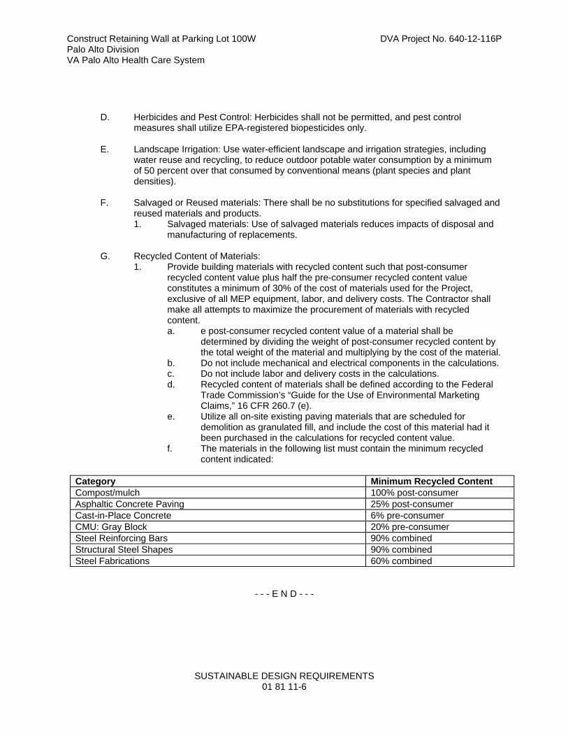
Construct Retaining Wall at Parking Lot 100W DVA Project No. 640-12-116P Palo Alto Division VA Palo Alto Health Care System
SUSTAINABLE DESIGN REQUIREMENTS 01 81 11-6
D. Herbicides and Pest Control: Herbicides shall not be permitted, and pest control measures shall utilize EPA-registered biopesticides only.
E. Landscape Irrigation: Use water-efficient landscape and irrigation strategies, including
water reuse and recycling, to reduce outdoor potable water consumption by a minimum of 50 percent over that consumed by conventional means (plant species and plant densities).
F. Salvaged or Reused materials: There shall be no substitutions for specified salvaged and reused materials and products. 1. Salvaged materials: Use of salvaged materials reduces impacts of disposal and
manufacturing of replacements.
G. Recycled Content of Materials: 1. Provide building materials with recycled content such that post-consumer
recycled content value plus half the pre-consumer recycled content value constitutes a minimum of 30% of the cost of materials used for the Project, exclusive of all MEP equipment, labor, and delivery costs. The Contractor shall make all attempts to maximize the procurement of materials with recycled content. a. e post-consumer recycled content value of a material shall be
determined by dividing the weight of post-consumer recycled content by the total weight of the material and multiplying by the cost of the material.
b. Do not include mechanical and electrical components in the calculations. c. Do not include labor and delivery costs in the calculations. d. Recycled content of materials shall be defined according to the Federal
Trade Commission’s “Guide for the Use of Environmental Marketing Claims,” 16 CFR 260.7 (e).
e. Utilize all on-site existing paving materials that are scheduled for demolition as granulated fill, and include the cost of this material had it been purchased in the calculations for recycled content value.
f. The materials in the following list must contain the minimum recycled content indicated:
Category Minimum Recycled Content Compost/mulch 100% post-consumer Asphaltic Concrete Paving 25% post-consumer Cast-in-Place Concrete 6% pre-consumer CMU: Gray Block 20% pre-consumer Steel Reinforcing Bars 90% combined Structural Steel Shapes 90% combined Steel Fabrications 60% combined
- - - E N D - - -
Construct Retaining Wall at Parking Lot 100W DVA Project No. 640-12-116P Palo Alto Division VA Palo Alto Health Care System
DEMOLITION 02 41 00 - 1
SECTION 02 41 00
DEMOLITION
PART 1 - GENERAL
1.1 DESCRIPTION
A. This section specifies demolition and removal of buildings, portions of buildings, utilities, other structures and debris from trash dumps shown.
1.2 RELATED WORK
A. Demolition and removal of roads, walks, curbs, and on-grade slabs outside buildings to be demolished: Section 31 20 00, EARTH MOVING.
B. Safety Requirements: GENERAL CONDITIONS Article, ACCIDENT PREVENTION.
C. Disconnecting utility services prior to demolition: Section 01 00 00, GENERAL REQUIREMENTS.
D. Reserved items that are to remain the property of the Government: Section 01 00 00, GENERAL REQUIREMENTS.
E. Asbestos Removal: Section 02 82 11, TRADITIONAL ASBESTOS ABATEMENT.
F. Lead Paint: Section 02 83 33.13, LEAD-BASED PAINT REMOVAL AND DISPOSAL.
G. Environmental Protection: Section 01 57 19, TEMPORARY ENVIRONMENTAL CONTROLS.
H. Construction Waste Management: Section 017419 CONSTRUCTION WASTE MANAGEMENT.
I. Infectious Control: Section 01 00 00, GENERAL REQUIREMENTS, Article 1.7, INFECTION PREVENTION MEASURES.
1.3 PROTECTION
A. Perform demolition in such manner as to eliminate hazards to persons and property; to minimize interference with use of adjacent areas, utilities and structures or interruption of use of such utilities; and to provide free passage to and from such adjacent areas of structures. Comply with requirements of GENERAL CONDITIONS Article, ACCIDENT PREVENTION.
B. Provide safeguards, including warning signs, barricades, temporary fences, warning lights, and other similar items that are required for protection of all personnel during demolition and removal operations. Comply with requirements of Section 01 00 00, GENERAL REQUIREMENTS, Article PROTECTION OF EXISTING VEGETATION, STRUCTURES, EQUIPMENT, UTILITIES AND IMPROVEMENTS.
C. Maintain fences, barricades, lights, and other similar items around exposed excavations until such excavations have been completely filled.
D. Provide enclosed dust chutes with control gates from each floor to carry debris to truck beds and govern flow of material into truck. Provide overhead bridges of tight board or prefabricated metal construction at dust chutes to protect persons and property from falling debris.
E. Prevent spread of flying particles and dust. Sprinkle rubbish and debris with water to keep dust to a minimum. Do not use water if it results in hazardous or objectionable condition such as, but not limited to; ice, flooding, or pollution. Vacuum and dust the work area daily.

Construct Retaining Wall at Parking Lot 100W DVA Project No. 640-12-116P Palo Alto Division VA Palo Alto Health Care System
DEMOLITION 02 41 00 - 2
F. In addition to previously listed fire and safety rules to be observed in performance of work, include following:
1. No wall or part of wall shall be permitted to fall outwardly from structures.
2. Maintain at least one stairway in each structure in usable condition to highest remaining floor. Keep stairway free of obstructions and debris until that level of structure has been removed.
3. Wherever a cutting torch or other equipment that might cause a fire is used, provide and maintain fire extinguishers nearby ready for immediate use. Instruct all possible users in use of fire extinguishers.
4. Keep hydrants clear and accessible at all times. Prohibit debris from accumulating within a radius of 4500 mm (15 feet) of fire hydrants.
G. Before beginning any demolition work, the Contractor shall survey the site and examine the drawings and specifications to determine the extent of the work. The contractor shall take necessary precautions to avoid damages to existing items to remain in place, to be reused, or to remain the property of the Medical Centerany damaged items shall be repaired or replaced as approved by the Resident Engineer. The Contractor shall coordinate the work of this section with all other work and shall construct and maintain shoring, bracing, and supports as required. The Contractor shall ensure that structural elements are not overloaded and shall be responsible for increasing structural supports or adding new supports as may be required as a result of any cutting, removal, or demolition work performed under this contract. Do not overload structural elements. Provide new supports and reinforcement for existing construction weakened by demolition or removal works. Repairs, reinforcement, or structural replacement must have Resident Engineer’s approval.
H. The work shall comply with the requirements of Section 01 57 19, TEMPORARY ENVIRONMENTAL CONTROLS.
I. The work shall comply with the requirements of Section 01 00 00, GENERAL REQUIREMENTS, Article 1.7 INFECTION PREVENTION MEASURES.
1.4 UTILITY SERVICES
A. Demolish and remove outside utility service lines shown to be removed.
B. Remove abandoned outside utility lines that would interfere with installation of new utility lines and new construction.
PART 2 - PRODUCTS (NOT USED)
PART 3 - EXECUTION
3.1 DEMOLITION
A. Completely demolish and remove buildings and structures, including all appurtenances related or connected thereto, as noted below:
1. As required for installation of new utility service lines.
2. To full depth within an area defined by hypothetical lines located 1500 mm (5 feet) outside building lines of new structures.

Construct Retaining Wall at Parking Lot 100W DVA Project No. 640-12-116P Palo Alto Division VA Palo Alto Health Care System
DEMOLITION 02 41 00 - 3
B. Debris, including brick, concrete, stone, metals and similar materials shall become property of Contractor and shall be disposed of by him daily, off the Medical Center to avoid accumulation at the demolition site. Materials that cannot be removed daily shall be stored in areas specified by the Resident Engineer. Break up concrete slabs below grade that do not require removal from present location into pieces not exceeding 600 mm (24 inches) square to permit drainage. Contractor shall dispose debris in compliance with applicable federal, state or local permits, rules and/or regulations.
C. In removing buildings and structures of more than two stories, demolish work story by story starting at highest level and progressing down to third floor level. Demolition of first and second stories may proceed simultaneously.
D. Remove and legally dispose of all materials, other than earth to remain as part of project work, from any trash dumps shown. Materials removed shall become property of contractor and shall be disposed of in compliance with applicable federal, state or local permits, rules and/or regulations. All materials in the indicated trash dump areas, including above surrounding grade and extending to a depth of 1500 mm (5 feet) below surrounding grade, shall be included as part of the lump sum compensation for the work of this section. Materials that are located beneath the surface of the surrounding ground more than 1500 mm (5 feet), or materials that are discovered to be hazardous, shall be handled as unforeseen. The removal of hazardous material shall be referred to Hazardous Materials specifications.
E. Remove existing utilities as indicated or uncovered by work and terminate in a manner conforming to the nationally recognized code covering the specific utility and approved by the Resident Engineer. When Utility lines are encountered that are not indicated on the drawings, the Resident Engineer shall be notified prior to further work in that area.
3.2 CLEAN-UP
A. On completion of work of this section and after removal of all debris, leave site in clean condition satisfactory to Resident Engineer. Clean-up shall include off the Medical Center disposal of all items and materials not required to remain property of the Government as well as all debris and rubbish resulting from demolition operations.
--- E N D---

Construct Retaining Wall at Parking Lot 100W DVA Project No. 640-12-116P VAPAHCS Palo Alto, CA
SECTION 03 30 00
CAST-IN-PLACE CONCRETE
PART 1 - GENERAL
1.1 DESCRIPTION:
This section specifies cast-in-place structural concrete and materials and mixes for other
concrete.
1.2 RELATED WORK:
A. Materials testing and inspection during construction: Section 01 45 29, TESTING LABORATORY
SERVICES.
B. Concrete roads, walks, and similar exterior site work: Section 32 05 23, CEMENT AND
CONCRETE FOR EXTERIOR IMPROVEMENTS.
1.3 TESTING AGENCY FOR CONCRETE MIX DESIGN:
A. Testing agency for the trial concrete mix design retained and reimbursed by the Contractor and
approved by Resident Engineer. For all other testing, refer to Section 01 45 29 Testing
Laboratory Services.
B. Testing agency maintaining active participation in Program of Cement and Concrete Reference
Laboratory (CCRL) of National Institute of Standards and Technology.
C. Testing agency shall furnish equipment and qualified technicians to establish proportions of
ingredients for concrete mixes.
1.4 TOLERANCES:
A. Formwork: ACI 117, except the elevation tolerance of formed surfaces before removal of shores
is +0 mm (+0 inch) and -20 mm (-3/4 inch).
B. Reinforcement Fabricating and Placing: ACI 117, except that fabrication tolerance for bar sizes
Nos. 10, 13, and 16 (Nos. 3, 4, and 5) (Tolerance Symbol 1 in Fig. 2.1(a), ACI, 117) used as
column ties or stirrups is +0 mm (+0 inch) and -13 mm (-1/2 inch) where gross bar length is less
than 3600 mm (12 feet), or +0 mm (+0 inch) and -20 mm (-3/4 inch) where gross bar length is
3600 mm (12 feet) or more.
C. Cross-Sectional Dimension: ACI 117, except tolerance for thickness of slabs 12 inches or less is
+20 mm (+3/4 inch) and - 6 mm (-1/4 inch). Tolerance of thickness of beams more than 300 mm
(12 inch) but less than 900 mm (3 feet) is +20 mm (+3/4 inch) and -10 mm (-3/8 inch).
D. Slab Finishes: ACI 117, Section 4.5.6, F-number method in accordance with ASTM E1155,
except as follows:
1. Test entire slab surface, including those areas within 600 mm (2 feet) of construction joints
and vertical elements that project through slab surface.
2. Maximum elevation change which may occur within 600 mm (2 feet) of any column or wall
element is 6 mm (0.25 inches).

Construct Retaining Wall at Parking Lot 100W DVA Project No. 640-12-116P VAPAHCS Palo Alto, CA
03 30 00 - 2
3. Allow sample measurement lines that are perpendicular to construction joints to extend past
joint into previous placement no further than 1500 mm (5 feet).
1.5 REGULATORY REQUIREMENTS:
A. ACI SP-66 – ACI Detailing Manual.
B. ACI 318 - Building Code Requirements for Reinforced Concrete.
C. ACI 301 – Standard Specifications for Structural Concrete.
1.6 SUBMITTALS:
A. Submit in accordance with Section 01 33 23, SHOP DRAWINGS, PRODUCT DATA, and
SAMPLES.
B. Shop Drawings: Reinforcing steel: Complete shop drawings
C. Mill Test Reports:
1. Reinforcing Steel.
2. Cement.
D. Manufacturer's Certificates:
1. Abrasive aggregate.
2. Lightweight aggregate for structural concrete.
3. Air-entraining admixture.
4. Chemical admixtures, including chloride ion content.
5. Waterproof paper for curing concrete.
6. Liquid membrane-forming compounds for curing concrete.
7. Non-shrinking grout.
8. Liquid hardener.
9. Waterstops.
10. Expansion joint filler.
11. Adhesive binder.
E. Testing Agency for Concrete Mix Design: Approval request including qualifications of principals
and technicians and evidence of active participation in program of Cement and Concrete
Reference Laboratory (CCRL) of National Institute of Standards and Technology.
F. Test Report for Concrete Mix Designs: Trial mixes including water-cement, ratio curves, concrete
mix ingredients, and admixtures.
G. Shoring and Reshoring Sequence: Submit for approval a shoring and reshoring sequence for flat
slab/flat plate portions, prepared by a registered Professional Engineer. As a minimum, include
timing of form stripping, reshoring, number of floors to be re-shored and timing of re-shore
removal to serve as an initial outline of procedures subject to modification as construction
progresses. Submit revisions to sequence, whether initiated by Resident Engineer (see
FORMWORK) or Contractor.
Construct Retaining Wall at Parking Lot 100W DVA Project No. 640-12-116P VAPAHCS Palo Alto, CA
03 30 00 - 3
1.7 DELIVERY, STORAGE, AND HANDLING:
A. Conform to ACI 304. Store aggregate separately for each kind or grade, to prevent segregation of
sizes and avoid inclusion of dirt and other materials.
B. Deliver cement in original sealed containers bearing name of brand and manufacturer, and
marked with net weight of contents. Store in suitable watertight building in which floor is raised at
least 300 mm (1 foot) above ground.
C. Deliver other packaged materials for use in concrete in original sealed containers, plainly marked
with manufacturer's name and brand, and protect from damage until used.
1.8 PRE-CONCRETE CONFERENCE:
A. General: At least 15 days prior to submittal of design mixes, conduct a meeting to review
proposed methods of concrete construction to achieve the required results.
B. Agenda: Includes but is not limited to:
1. Submittals.
2. Coordination of work.
3. Availability of material.
4. Concrete mix design including admixtures.
5. Methods of placing, finishing, and curing.
6. Finish criteria required to obtain required flatness and levelness.
7. Timing of floor finish measurements.
8. Material inspection and testing.
C. Attendees: Include but not limited to representatives of Contractor; subcontractors involved in
supplying, conveying, placing, finishing, and curing concrete; lightweight aggregate manufacturer;
admixture manufacturers; Resident Engineer; Consulting Engineer; Department of Veterans
Affairs retained testing laboratories for concrete testing and finish (F-number) verification.
D. Minutes of the meeting: Contractor shall take minutes and type and distribute the minutes to
attendees within five days of the meeting.
1.10 APPLICABLE PUBLICATIONS:
A. Publications listed below form a part of this specification to extent referenced. Publications are
referenced in text by basic designation only.
B. American Concrete Institute (ACI):
117-10 ........................................ Specifications for Tolerances for Concrete Construction and
Materials and Commentary
211.1-91(R2009) ........................ Standard Practice for Selecting Proportions for Normal,
Heavyweight, and Mass Concrete
211.2-98(R2004) ........................ Standard Practice for Selecting Proportions for Structural
Lightweight Concrete
214R-11 ..................................... Guide to Evaluation of Strength Test Results of Concrete

Construct Retaining Wall at Parking Lot 100W DVA Project No. 640-12-116P VAPAHCS Palo Alto, CA
03 30 00 - 4
301-10 ........................................ Standard Practice for Structural Concrete
304R-00(R2009) ........................ Guide for Measuring, Mixing, Transporting, and Placing
Concrete
305.1-06 ..................................... Specification for Hot Weather Concreting
306.1-90(R2002) ........................ Standard Specification for Cold Weather Concreting
308.1-11 ..................................... Specification for Curing Concrete
309R-05 ..................................... Guide for Consolidation of Concrete
318-11 ........................................ Building Code Requirements for Structural Concrete and
Commentary
347-04 ........................................ Guide to Formwork for Concrete
SP-66-04 .................................... ACI Detailing Manual
C. American National Standards Institute and American Hardboard Association (ANSI/AHA):
A135.4-2004 ............................... Basic Hardboard
D. American Society for Testing and Materials (ASTM):
A82/A82M-07 ............................. Standard Specification for Steel Wire, Plain, for Concrete
Reinforcement
A185/185M-07 ............................ Standard Specification for Steel Welded Wire Reinforcement,
Plain, for Concrete
A615/A615M-09 ......................... Standard Specification for Deformed and Plain Carbon Steel
Bars for Concrete Reinforcement
A653/A653M-11 ......................... Standard Specification for Steel Sheet, Zinc Coated
(Galvanized) or Zinc Iron Alloy Coated (Galvannealed) by the
Hot Dip Process
A706/A706M-09 ......................... Standard Specification for Low Alloy Steel Deformed and Plain
Bars for Concrete Reinforcement
A767/A767M-09 ......................... Standard Specification for Zinc Coated (Galvanized) Steel Bars
for Concrete Reinforcement
A775/A775M-07 ......................... Standard Specification for Epoxy Coated Reinforcing Steel Bars
A820-11 ...................................... Standard Specification for Steel Fibers for Fiber Reinforced
Concrete
A996/A996M-09 ......................... Standard Specification for Rail Steel and Axle Steel Deformed
Bars for Concrete Reinforcement
C31/C31M-10 ............................. Standard Practice for Making and Curing Concrete Test
Specimens in the field
C33/C33M-11A .......................... Standard Specification for Concrete Aggregates
C39/C39M-12 ............................. Standard Test Method for Compressive Strength of Cylindrical
Concrete Specimens
Construct Retaining Wall at Parking Lot 100W DVA Project No. 640-12-116P VAPAHCS Palo Alto, CA
03 30 00 - 5
C94/C94M-12 ............................. Standard Specification for Ready Mixed Concrete
C143/C143M-10 ......................... Standard Test Method for Slump of Hydraulic Cement Concrete
C150-11 ..................................... Standard Specification for Portland Cement
C171-07 ..................................... Standard Specification for Sheet Materials for Curing Concrete
C172-10 ..................................... Standard Practice for Sampling Freshly Mixed Concrete
C173-10... .................................. Standard Test Method for Air Content of Freshly Mixed Concrete
by the Volumetric Method
C192/C192M-07 ......................... Standard Practice for Making and Curing Concrete Test
Specimens in the Laboratory
C231-10 ..................................... Standard Test Method for Air Content of Freshly Mixed Concrete
by the Pressure Method
C260-10 ..................................... Standard Specification for Air Entraining Admixtures for
Concrete
C309-11 ..................................... Standard Specification for Liquid Membrane Forming
Compounds for Curing Concrete
C330-09 ..................................... Standard Specification for Lightweight Aggregates for Structural
Concrete
C494/C494M-11 ......................... Standard Specification for Chemical Admixtures for Concrete
C666/C666M-03(R2008) ............ Standard Test Method for Resistance of Concrete to Rapid
Freezing and Thawing
C881/C881M-10 ......................... Standard Specification for Epoxy Resin Base Bonding Systems
for Concrete
C1107/1107M-11 ....................... Standard Specification for Packaged Dry, Hydraulic-Cement
Grout (Non-shrink)
C1315-11 ................................... Standard Specification for Liquid Membrane Forming
Compounds Having Special Properties for Curing and Sealing
Concrete
D6-95(R2011) ............................ Standard Test Method for Loss on Heating of Oil and Asphaltic
Compounds
D297-93(R2006) ........................ Standard Methods for Rubber Products Chemical Analysis
D412—06AE2 ............................ Standard Test Methods for Vulcanized Rubber and
Thermoplastic Elastomers - Tension
D1751-04(R2008) ...................... Standard Specification for Preformed Expansion Joint Filler for
Concrete Paving and Structural Construction (Non-extruding and
Resilient Bituminous Types)
D4263-83(2012) ......................... Standard Test Method for Indicating Moisture in Concrete by the
Plastic Sheet Method.

Construct Retaining Wall at Parking Lot 100W DVA Project No. 640-12-116P VAPAHCS Palo Alto, CA
03 30 00 - 6
D4397-10 ................................... Standard Specification for Polyethylene Sheeting for
Construction, Industrial and Agricultural Applications
E1155-96(R2008) ...................... Standard Test Method for Determining FF Floor Flatness and FL
Floor Levelness Numbers
F1869-11 .................................... Standard Test Method for Measuring Moisture Vapor Emission
Rate of Concrete Subfloor Using Anhydrous Calcium Chloride.
E. American Welding Society (AWS):
D1.4/D1.4M-11 ........................... Structural Welding Code - Reinforcing Steel
F. Concrete Reinforcing Steel Institute (CRSI):
Handbook 2008
G. National Cooperative Highway Research Program (NCHRP):
Report On ................................... Concrete Sealers for the Protection of Bridge Structures
H. U. S. Department of Commerce Product Standard (PS):
PS 1 ............................................ Construction and Industrial Plywood
PS 20.......................................... American Softwood Lumber
I. U. S. Army Corps of Engineers Handbook for Concrete and Cement:
CRD C513 .................................. Rubber Waterstops
CRD C572 .................................. Polyvinyl Chloride Waterstops
PART 2 – PRODUCTS:
2.1 FORMWORK MATERIALS
A. For Exposed Smooth Form-finished Concrete: Use Medium Density (or better) Overlaid Concrete
Form Exterior (MDO), to provide continuous straight, smooth, exposed surfaces without grain
patterns. Furnish in largest practicable sizes to minimize number of joints and to conform to a
joint system as approved by the COTR.
B. For all planter walls: Laminate-lined wood, extra smooth form finish by Olympic Panel, or equal.
C. Chamfer Strips: Meadow-Burke Concrete Accessories, PVC type CSF ½-inch or as otherwise
noted, all exposed corners.
D. Form Release Agent: Must not stain or otherwise adversely affect architectural concrete
surfaces. “Nox-Crete Form Coating”; Industrial Synthetics Corp.’s “Synthex”; or equal.
E. Do not use forms if they vary from a straight line more than 3 mm (1/8 inch) in any 3000 mm (ten
foot) long section, in either a horizontal or vertical direction.
F. Wood forms should be at least 50 mm (2 inches) thick (nominal). Wood forms shall also be free
from warp, twist, loose knots, splits, or other defects. Use approved flexible or curved forms for
forming radii.
G. Form Ties: Develop a minimum working strength of 13.35 kN (3000 pounds) when fully
assembled. Ties shall be adjustable in length to permit tightening of forms and not have any lugs,
Construct Retaining Wall at Parking Lot 100W DVA Project No. 640-12-116P VAPAHCS Palo Alto, CA
03 30 00 - 7
cones, washers to act as spreader within form, nor leave a hole larger than 20 mm (3/4 inch)
diameter, or a depression in exposed concrete surface, or leave metal closer than 40 mm (1 1/2
inches) to concrete surface. Wire ties not permitted. Cutting ties back from concrete face not
permitted.
2.2 MATERIALS:
A. Cement: ASTM C150 Type I. Use white Portland Cement at exposed concrete walls and where
noted on drawings.
B. Coarse Aggregate: ASTM C33.
1. Size 67 or Size 467 may be used for footings and walls over 300 mm (12 inches) thick.
2. Coarse aggregate for applied topping, encasement of steel columns, and metal pan stair fill
shall be Size 7.
3. Maximum size of coarse aggregates not more than one-fifth of narrowest dimension between
sides of forms, one-third of depth of slabs, nor three-fourth of minimum clear spacing
between reinforcing bars.
C. Lightweight Aggregates for Structural Concrete: ASTM C330, Table 1. Maximum size of
aggregate not larger than one-fifth of narrowest dimension between forms, nor three-fourth of
minimum clear distance between reinforcing bars. Contractor to furnish certified report to verify
that aggregate is sound and durable, and has a durability factor of not less than 80 based on 300
cycles of freezing and thawing when tested in accordance with ASTM C666.
D. Fine Aggregate: ASTM C33. Fine aggregate for applied concrete floor topping shall pass a 4.75
mm (No. 4) sieve, 10 percent maximum shall pass a 150 µm (No. 100) sieve.
E. Mixing Water: Fresh, clean, and potable.
F. Admixtures:
1. Water Reducing Admixture: ASTM C494, Type A and not contain more chloride ions than are
present in municipal drinking water.
2. Water Reducing, Retarding Admixture: ASTM C494, Type D and not contain more chloride
ions than are present in municipal drinking water.
3. High-Range Water-Reducing Admixture (Superplasticizer): ASTM C494, Type F or G, and
not contain more chloride ions than are present in municipal drinking water.
4. Non-Corrosive, Non-Chloride Accelerator: ASTM C494, Type C or E, and not contain more
chloride ions than are present in municipal drinking water. Admixture manufacturer must
have long-term non-corrosive test data from an independent testing laboratory of at least one
year duration using an acceptable accelerated corrosion test method such as that using
electrical potential measures.
5. Air Entraining Admixture: ASTM C260.
6. Calcium Nitrite corrosion inhibitor: ASTM C494 Type C.
Construct Retaining Wall at Parking Lot 100W DVA Project No. 640-12-116P VAPAHCS Palo Alto, CA
03 30 00 - 8
7. Prohibited Admixtures: Calcium chloride, thiocyanate or admixtures containing more than
0.05 percent chloride ions are not permitted.
8. Certification: Written conformance to the requirements above and the chloride ion content of
the admixture prior to mix design review.
G. Vapor Barrier: ASTM D4397, 0.25 mm (10 mil).
H. Reinforcing Steel: ASTM A615, or ASTM A996, deformed, grade as shown.
I. Welded Wire Fabric: ASTM A185.
J. Reinforcing Bars to be Welded: ASTM A706.
K. Galvanized Reinforcing Bars: ASTM A767.
L. Epoxy Coated Reinforcing Bars: ASTM A775.
M. Reinforcement for Concrete Fireproofing: 100 mm x 100 mm x 3.4 mm diameter (4 x 4-W1.4 x
W1.4) welded wire fabric, secured in place to hold mesh 20 mm (3/4 inch) away from steel. Mesh
at steel columns shall be wired to No. 10 (No. 3) vertical corner steel bars.
N. Reinforcement for Metal Pan Stair Fill: 50 mm (2 inch) wire mesh, either hexagonal mesh at
.8Kg/m2 (1.5 pounds per square yard), or square mesh at .6Kg/m2 (1.17 pounds per square yard).
O. Supports, Spacers, and Chairs: Types which will hold reinforcement in position shown in
accordance with requirements of ACI 318 except as specified.
P. Expansion Joint Filler: ASTM D1751.
Q. Sheet Materials for Curing Concrete: ASTM C171.
R. Liquid Membrane-forming Compounds for Curing Concrete: ASTM C309, Type I, with fugitive
dye, and shall meet the requirements of ASTM C1315.Compound shall be compatible with
scheduled surface treatment, such as paint and resilient tile, and shall not discolor concrete
surface.
S. Abrasive Aggregate: Aluminum oxide grains or emery grits.
T. Moisture Vapor Emissions & Alkalinity Control Sealer: 100% active colorless aqueous siliconate
solution concrete surface.
1. ASTM C1315 Type 1 Class A, and ASTM C309 Type 1 Class A, penetrating product to have
no less than 34% solid content, leaving no sheen, volatile organic compound (VOC) content
rating as required to suite regulatory requirements. The product shall have at least a five (5)
year documented history in controlling moisture vapor emission from damaging floor
covering, compatible with all finish materials.
2. MVE 15-Year Warranty:
a. When a floor covering is installed on a below grade, on grade, or above grade concrete
slab treated with Moisture Vapor Emissions & Alkalinity Control Sealer according to
manufacturer’s instruction, sealer manufacturer shall warrant the floor covering system
against failure due to moisture vapor migration or moisture-born contaminates for a
period of fifteen (15) years from the date of original installation. The warranty shall cover

Construct Retaining Wall at Parking Lot 100W DVA Project No. 640-12-116P VAPAHCS Palo Alto, CA
03 30 00 - 9
all labor and materials needed to replace all floor covering that fails due to moisture
vapor emission & moisture born contaminates.
U. Penetrating Sealer: For use on parking garage ramps and decks. High penetration silane sealer
providing minimum 95 percent screening per National Cooperative Highway Research Program
(NCHRP) No. 244 standards for chloride ion penetration resistance. Requires moist (non-
membrane) curing of slab.
V. Non-Shrink Grout:
1. ASTM C1107, pre-mixed, produce a compressive strength of at least 18 MPa at three days
and 35 MPa (5000 psi) at 28 days. Furnish test data from an independent laboratory
indicating that the grout when placed at a fluid consistency shall achieve 95 percent bearing
under a 1200 mm x 1200 mm (4 foot by 4 foot) base plate.
2. Where high fluidity or increased placing time is required, furnish test data from an
independent laboratory indicating that the grout when placed at a fluid consistency shall
achieve 95 percent under an 450 mm x 900 mm (18 inch by 36 inch) base plate.
W. Adhesive Binder: ASTM C881.
AA. Waterstops:
1. Polyvinyl Chloride Waterstop: CRD C572.
2. Rubber Waterstops: CRD C513.
3. Bentonite Waterstop: Flexible strip of bentonite 25 mm x 20 mm (1 inch by 3/4 inch),
weighing 8.7 kg/m (5.85 lbs. per foot) composed of Butyl Rubber Hydrocarbon (ASTM D297),
Bentonite (SS-S-210-A) and Volatile Matter (ASTM D6).
4. Non-Metallic Hydrophilic: Swellable strip type compound of polymer modified chloroprene
rubber that swells upon contact with water shall conform to ASTM D412 as follows: Tensile
strength 420 psi minimum; ultimate elongation 600 percent minimum. Hardness shall be 50
minimum on the type A durameter and the volumetric expansion ratio in in 70 deg water shall
be 3 to 1 minimum.
BB. Porous Backfill: Crushed stone or gravel graded from 25 mm to 20 mm (1 inch to 3/4 inch).
CC. Fibers:
1. Synthetic Fibers: Monofilament or fibrillated polypropylene fibers for secondary reinforcing of
concrete members. Use appropriate length and 0.9 kg/m3 (1.5 lb. per cubic yard). Product
shall have a UL rating.
2. Steel Fibers: ASTM A820, Type I cold drawn, high tensile steel wire for use as primary
reinforcing in slab-on-grade. Minimum dosage rate 18 kg/m3 (30 lb. per cubic yard).
DD. Epoxy Joint Filler: Two component, 100 percent solids compound, with a minimum shore D
hardness of 50.
EE. Bonding Admixture: Non-rewettable, polymer modified, bonding compound.
Construct Retaining Wall at Parking Lot 100W DVA Project No. 640-12-116P VAPAHCS Palo Alto, CA
03 30 00 - 10
FF. Architectural Concrete: For areas designated as architectural concrete on the Contract
Documents, use colored cements and specially selected aggregates as necessary to produce a
concrete of a color and finish which exactly matches the designated sample panel.
2.3 CONCRETE MIXES:
A. Mix Designs: Proportioned in accordance with Section 5.3, "Proportioning on the Basis of Field
Experience and/or Trial Mixtures" of ACI 318.
1. If trial mixes are used, make a set of at least 6 cylinders in accordance with ASTM C192 for
test purposes from each trial mix; test three for compressive strength at 7 days and three at
28 days.
2. Submit a report of results of each test series, include a detailed listing of the proportions of
trial mix or mixes, including cemen, admixtures, weight of fine and coarse aggregate per m3
(cubic yard) measured dry rodded and damp loose, specific gravity, fineness modulus,
percentage of moisture, air content, water-cement ratio, and consistency of each cylinder in
terms of slump.
3. Prepare a curve showing relationship between water-cement ratio at 7-day and 28-day
compressive strengths. Plot each curve using at least three specimens.
4. If the field experience method is used, submit complete standard deviation analysis.
B. After approval of mixes no substitution in material or change in proportions of approval mixes
may be made without additional tests and approval of Resident Engineer or as specified. Making
and testing of preliminary test cylinders may be carried on pending approval of cement, providing
Contractor and manufacturer certify that ingredients used in making test cylinders are the same.
Resident Engineer may allow Contractor to proceed with depositing concrete for certain portions
of work, pending final approval of cement approval of design mix.
C. Cement Factor: Maintain minimum cement factors in Table I regardless of compressive strength
developed above minimums.

Construct Retaining Wall at Parking Lot 100W DVA Project No. 640-12-116P VAPAHCS Palo Alto, CA
03 30 00 - 11
TABLE I - CEMENT AND WATER FACTORS FOR CONCRETE
Concrete Strength Non-Air-Entrained Air-Entrained
Min. 28 Day Comp. Str.
MPa (psi)
Min. Cement kg/m3 (lbs/c. yd)
Max. Water Cement Ratio
Min. Cement
kg/m3 (lbs/c. yd)
Max. Water Cement Ratio
35 (5000)1,3 375 (630) 0.45 385 (650) 0.40
30 (4000)1,3 325 (550) 0.55 340 (570) 0.50
25 (3000)1,3 280 (470) 0.65 290 (490) 0.55
25 (3000)1,2 300 (500) * 310 (520) *
1. If trial mixes are used, the proposed mix design shall achieve a compressive strength 8.3
MPa (1200 psi) in excess of f'c. For concrete strengths above 35 Mpa (5000 psi), the
proposed mix design shall achieve a compressive strength 9.7 MPa (1400 psi) in excess of
f’c.
2. Lightweight Structural Concrete. Pump mixes may require higher cement values.
3. For concrete exposed to high sulfate content soils maximum water cement ratio is 0.44.
4. Determined by Laboratory in accordance with ACI 211.1 for normal concrete or ACI 211.2 for
lightweight structural concrete.
E. Maximum Slump: Maximum slump, as determined by ASTM C143 with tolerances as established
by ASTM C94, for concrete to be vibrated shall be as shown in Table II.
TABLE II - MAXIMUM SLUMP, MM (INCHES)*
Type of Construction Normal Weight Concrete
Lightweight Structural Concrete
Reinforced Footings and Substructure Walls
75mm (3 inches) 75 mm (3 inches)
Slabs, Beams, Reinforced Walls, and Building Columns
100 mm (4 inches) 100 mm (4 inches)
F. Slump may be increased by the use of the approved high-range water-reducing admixture
(superplasticizer). Tolerances as established by ASTM C94. Concrete containing the high-range-
water-reducing admixture may have a maximum slump of 225 mm (9 inches). The concrete shall
arrive at the job site at a slump of 50 mm to 75 mm (2 inches to 3 inches), and 75 mm to 100 mm
(3 inches to 4 inches) for lightweight concrete. This should be verified, and then the high-range-
water-reducing admixture added to increase the slump to the approved level.

Construct Retaining Wall at Parking Lot 100W DVA Project No. 640-12-116P VAPAHCS Palo Alto, CA
03 30 00 - 12
G. Air-Entrainment: Air-entrainment of normal weight concrete shall conform with Table III. Air-
entrainment of lightweight structural concrete shall conform with Table IV. Determine air content
by either ASTM C173 or ASTM C231.
TABLE III - TOTAL AIR CONTENT FOR VARIOUS SIZES OF COARSE AGGREGATES (NORMAL CONCRETE)
Nominal Maximum Size of Total Air Content
Coarse Aggregate, mm (Inches) Percentage by Volume
10 mm (3/8 in).6 to 10 13 mm (1/2 in).5 to 9
20 mm (3/4 in).4 to 8 25 mm (1 in).3-1/2 to 6-1/2
40 mm (1 1/2 in).3 to 6
TABLE IV AIR CONTENT OF LIGHTWEIGHT STRUCTURAL CONCRETE
Nominal Maximum size of Total Air Content
Coarse Aggregate, mm’s (Inches) Percentage by Volume
Greater than 10 mm (3/8 in) 4 to 8
10 mm (3/8 in) or less 5 to 9
H. High early strength concrete, made with Type III cement or Type I cement plus non-corrosive
accelerator, shall have a 7-day compressive strength equal to specified minimum 28-day
compressive strength for concrete type specified made with standard Portland cement.
I. Lightweight structural concrete shall not weigh more than air-dry unit weight shown. Air-dry unit
weight determined on 150 mm by 300 mm (6 inch by 12 inch) test cylinders after seven days
standard moist curing followed by 21 days drying at 23 degrees C 1.7 degrees C (73.4 3
degrees Fahrenheit), and 50 (plus or minus 7) percent relative humidity. Use wet unit weight of
fresh concrete as basis of control in field.
J. Concrete slabs placed at air temperatures below 10 degrees C (50 degrees Fahrenheit) use non-
corrosive, non-chloride accelerator. Concrete required to be air entrained use approved air
entraining admixture. Pumped concrete, synthetic fiber concrete, architectural concrete, concrete
required to be watertight, and concrete with a water/cement ratio below 0.50 use high-range
water-reducing admixture (superplasticizer).
K. Durability: Use air entrainment for exterior exposed concrete subjected to freezing and thawing
and other concrete shown or specified. For air content requirements see Table III or Table IV.
L. Enforcing Strength Requirements: Test as specified in Section 01 45 29, TESTING
LABORATORY SERVICES, during the progress of the work. Seven-day tests may be used as
indicators of 28-day strength. Average of any three 28-day consecutive strength tests of
laboratory-cured specimens representing each type of concrete shall be equal to or greater than
specified strength. No single test shall be more than 3.5 MPa (500 psi) below specified strength.

Construct Retaining Wall at Parking Lot 100W DVA Project No. 640-12-116P VAPAHCS Palo Alto, CA
03 30 00 - 13
Interpret field test results in accordance with ACI 214. Should strengths shown by test specimens
fall below required values, Resident Engineer may require any one or any combination of the
following corrective actions, at no additional cost to the Government:
1. Require changes in mix proportions by selecting one of the other appropriate trial mixes or
changing proportions, including cement content, of approved trial mix.
2. Require additional curing and protection.
3. If five consecutive tests fall below 95 percent of minimum values given in Table I or if test
results are so low as to raise a question as to the safety of the structure, Resident Engineer
may direct Contractor to take cores from portions of the structure. Use results from cores
tested by the Contractor retained testing agency to analyze structure.
4. If strength of core drilled specimens falls below 85 percent of minimum value given in Table I,
Resident Engineer may order load tests, made by Contractor retained testing agency, on
portions of building so affected. Load tests in accordance with ACI 318 and criteria of
acceptability of concrete under test as given therein.
5. Concrete work, judged inadequate by structural analysis, by results of load test, or for any
reason, shall be reinforced with additional construction or replaced, if directed by the
Resident Engineer.
2.4 BATCHING AND MIXING:
A. General: Concrete shall be "Ready-Mixed" and comply with ACI 318 and ASTM C94, except as
specified. Batch mixing at the site is permitted. Mixing process and equipment must be approved
by Resident Engineer. With each batch of concrete, furnish certified delivery tickets listing
information in Paragraph 16.1 and 16.2 of ASTM C94. Maximum delivery temperature of concrete
is 380C (100 degrees Fahrenheit). Minimum delivery temperature as follows:
Atmospheric Temperature Minimum Concrete Temperature
-1. degrees to 4.4 degrees C
(30 degrees to 40 degrees F)
15.6 degrees C (60 degrees F.)
-17 degrees C to -1.1 degrees C (0 degrees to 30 degrees F.)
21 degrees C (70 degrees F.)
1. Services of aggregate manufacturer's representative shall be furnished during the design of
trial mixes and as requested by the Resident Engineer for consultation during batching,
mixing, and placing operations of lightweight structural concrete. Services will be required
until field controls indicate that concrete of required quality is being furnished. Representative
shall be thoroughly familiar with the structural lightweight aggregate, adjustment and control
of mixes to produce concrete of required quality. Representative shall assist and advise
Resident Engineer.
Construct Retaining Wall at Parking Lot 100W DVA Project No. 640-12-116P VAPAHCS Palo Alto, CA
03 30 00 - 14
PART 3 – EXECUTION
3.1 FORMWORK:
A. General: Design in accordance with ACI 347 is the responsibility of the Contractor. The
Contractor shall retain a registered Professional Engineer to design the formwork, shores, and
reshores.
1. Form boards and plywood forms may be reused for contact surfaces of exposed concrete
only if thoroughly cleaned, patched, and repaired and Resident Engineer approves their
reuse.
2. Provide forms for concrete footings unless Resident Engineer determines forms are not
necessary.
3. Corrugated fiberboard forms: Place forms on a smooth firm bed, set tight, with no buckled
cartons to prevent horizontal displacement, and in a dry condition when concrete is placed.
B. Treating and Wetting: Treat or wet contact forms as follows:
1. Coat plywood and board forms with non-staining form sealer. In hot weather, cool forms by
wetting with cool water just before concrete is placed.
2. Clean and coat removable metal forms with light form oil before reinforcement is placed. In
hot weather, cool metal forms by thoroughly wetting with water just before placing concrete.
3. Use sealer on reused plywood forms as specified for new material.
C. Size and Spacing of Studs: Size and space studs, wales and other framing members for wall
forms so as not to exceed safe working stress of kind of lumber used nor to develop deflection
greater than 1/270 of free span of member.
D. Unlined Forms: Use plywood forms to obtain a smooth finish for concrete surfaces. Tightly butt
edges of sheets to prevent leakage. Back up all vertical joints solidly and nail edges of adjacent
sheets to same stud with 6d box nails spaced not over 150 mm (6 inches) apart.
E. Lined Forms: May be used in lieu of unlined plywood forms. Back up form lining solidly with
square edge board lumber securely nailed to studs with all edges in close contact to prevent
bulging of lining. No joints in lining and backing may coincide. Nail abutted edges of sheets to
same backing board. Nail lining at not over 200 mm (8 inches) on center along edges and with at
least one nail to each square foot of surface area; nails to be 3d blued shingle or similar nails with
thin flatheads.
F. Architectural Liner: Attach liner as recommended by the manufacturer with tight joints to prevent
leakage.
G. Wall Form Ties: Locate wall form ties in symmetrically level horizontal rows at each line of wales
and in plumb vertical tiers. Space ties to maintain true, plumb surfaces. Provide one row of ties
within 150 mm (6 inches) above each construction joint. Space through-ties adjacent to horizontal
and vertical construction joints not over 450 mm (18 inches) on center.
Construct Retaining Wall at Parking Lot 100W DVA Project No. 640-12-116P VAPAHCS Palo Alto, CA
03 30 00 - 15
1. Tighten row of ties at bottom of form just before placing concrete and, if necessary, during
placing of concrete to prevent seepage of concrete and to obtain a clean line. Ties to be
entirely removed shall be loosened 24 hours after concrete is placed and shall be pulled from
least important face when removed.
2. Coat surfaces of all metal that is to be removed with paraffin, cup grease or a suitable
compound to facilitate removal.
H. Inserts, Sleeves, and Similar Items: Flashing reglets, steel strips, masonry ties, anchors, wood
blocks, nailing strips, grounds, inserts, wire hangers, sleeves, drains, guard angles, forms for
floor hinge boxes, inserts or bond blocks for elevator guide rails and supports, and other items
specified as furnished under this and other sections of specifications and required to be in their
final position at time concrete is placed shall be properly located, accurately positioned, and built
into construction, and maintained securely in place.
1. Locate inserts or hanger wires for furred and suspended ceilings only in bottom of concrete
joists, or similar concrete member of overhead concrete joist construction.
2. Install sleeves, inserts and similar items for mechanical services in accordance with drawings
prepared specially for mechanical services. Contractor is responsible for accuracy and
completeness of drawings and shall coordinate requirements for mechanical services and
equipment.
3. Do not install sleeves in beams, joists or columns except where shown or permitted by
Resident Engineer. Install sleeves in beams, joists, or columns that are not shown, but are
permitted by the Resident Engineer, and require no structural changes, at no additional cost
to the Government.
4. Minimum clear distance of embedded items such as conduit and pipe is at least three times
diameter of conduit or pipe, except at stub-ups and other similar locations.
5. Provide recesses and blockouts in floor slabs for door closers and other hardware as
necessary in accordance with manufacturer's instructions.
I. Construction Tolerances:
1. Set and maintain concrete formwork to assure erection of completed work within tolerances
specified and to accommodate installation of other rough and finish materials. Accomplish
remedial work necessary for correcting excessive tolerances. Erected work that exceeds
specified tolerance limits shall be remedied or removed and replaced, at no additional cost to
the Government.
2. Permissible surface irregularities for various classes of materials are defined as "finishes" in
specification sections covering individual materials. They are to be distinguished from
tolerances specified which are applicable to surface irregularities of structural elements.
3.2 PLACING REINFORCEMENT:
A. General: Details of concrete reinforcement in accordance with ACI 318 unless otherwise shown.

Construct Retaining Wall at Parking Lot 100W DVA Project No. 640-12-116P VAPAHCS Palo Alto, CA
03 30 00 - 16
B. Placing: Place reinforcement conforming to CRSI DA4, unless otherwise shown.
1. Place reinforcing bars accurately and tie securely at intersections and splices with 1.6 mm
(16 gauge) black annealed wire. Secure reinforcing bars against displacement during the
placing of concrete by spacers, chairs, or other similar supports. Portions of supports,
spacers, and chairs in contact with formwork shall be made of plastic in areas that will be
exposed when building is occupied. Type, number, and spacing of supports conform to ACI
318. Where concrete slabs are placed on ground, use concrete blocks or other
non-corrodible material of proper height, for support of reinforcement. Use of brick or stone
supports will not be permitted.
2. Lap welded wire fabric at least 1 1/2 mesh panels plus end extension of wires not less than
300 mm (12 inches) in structural slabs. Lap welded wire fabric at least 1/2 mesh panels plus
end extension of wires not less than 150 mm (6 inches) in slabs on grade.
3. Splice column steel at no points other than at footings and floor levels unless otherwise
shown.
C. Spacing: Minimum clear distances between parallel bars, except in columns and multiple layers
of bars in beams shall be equal to nominal diameter of bars. Minimum clear spacing is 25 mm (1
inch) or 1-1/3 times maximum size of coarse aggregate.
D. Splicing: Splices of reinforcement made only as required or shown or specified. Accomplish
splicing as follows:
1. Lap splices: Do not use lap splices for bars larger than Number 36 (Number 11). Minimum
lengths of lap as shown.
2. Welded splices: Splicing by butt-welding of reinforcement permitted providing the weld
develops in tension at least 125 percent of the yield strength (fy) for the bars. Welding
conform to the requirements of AWS D1.4. Welded reinforcing steel conform to the chemical
analysis requirements of AWS D1.4.
a. Submit test reports indicating the chemical analysis to establish weldability of reinforcing
steel.
b. Submit a field quality control procedure to insure proper inspection, materials and
welding procedure for welded splices.
c. Department of Veterans Affairs retained testing agency shall test a minimum of three
splices, for compliance, locations selected by Resident Engineer.
3. Mechanical Splices: Develop in tension and compression at least 125 percent of the yield
strength (fy) of the bars. Stresses of transition splices between two reinforcing bar sizes
based on area of smaller bar. Provide mechanical splices at locations indicated. Use
approved exothermic, tapered threaded coupling, or swaged and threaded sleeve. Exposed
threads and swaging in the field not permitted.

Construct Retaining Wall at Parking Lot 100W DVA Project No. 640-12-116P VAPAHCS Palo Alto, CA
03 30 00 - 17
a. Initial qualification: In the presence of Resident Engineer, make three test mechanical
splices of each bar size proposed to be spliced. Department of Veterans Affairs retained
testing laboratory will perform load test.
b. During installation: Furnish, at no additional cost to the Government, one companion
(sister) splice for every 50 splices for load testing. Department of Veterans Affairs
retained testing laboratory will perform the load test.
E. Bending: Bend bars cold, unless otherwise approved. Do not field bend bars partially embedded
in concrete, except when approved by Resident Engineer.
F. Cleaning: Metal reinforcement, at time concrete is placed, shall be free from loose flaky rust,
mud, oil, or similar coatings that will reduce bond.
G. Future Bonding: Protect exposed reinforcement bars intended for bonding with future work by
wrapping with felt and coating felt with a bituminous compound unless otherwise shown.
3.3 VAPOR BARRIER:
A. Except where membrane waterproofing is required, interior concrete slab on grade shall be
placed on a continuous vapor barrier.
1. Place 100 mm (4 inches) of fine granular fill over the vapor barrier to act as a blotter for
concrete slab.
2. Vapor barrier joints lapped 150 mm (6 inches) and sealed with compatible waterproof
pressure-sensitive tape.
3. Patch punctures and tears.
3.4 SLABS RECEIVING RESILIENT COVERING
A. Slab shall be allowed to cure for 6 weeks minimum prior to placing resilient covering. After
curing, slab shall be tested by the Contractor for moisture in accordance with ASTM D4263 or
ASTM F1869. Moisture content shall be less than 3 pounds per 1000 sf prior to placing covering.
B. In lieu of curing for 6 weeks, Contractor has the option, at his own cost, to utilize the Moisture
Vapor Emissions & Alkalinity Control Sealer as follows:
1. Sealer is applied on the day of the concrete pour or as soon as harsh weather permits, prior
to any other chemical treatments for concrete slabs either on grade, below grade or above
grade receiving resilient flooring, such as, sheet vinyl, vinyl composition tile, rubber, wood
flooring, epoxy coatings and overlays.
2. Manufacturer’s representative will be on the site the day of concrete pour to install or train its
application and document. He shall return on every application thereafter to verify that proper
procedures are followed.
a. Apply Sealer to concrete slabs as soon as final finishing operations are complete and the
concrete has hardened sufficiently to sustain floor traffic without damage.
b. Spray apply Sealer at the rate of 20 m2 (200 square feet) per gallon. Lightly broom
product evenly over the substrate and product has completely penetrated the surface.

Construct Retaining Wall at Parking Lot 100W DVA Project No. 640-12-116P VAPAHCS Palo Alto, CA
03 30 00 - 18
c. If within two (2) hours after initial application areas are subjected to heavy rainfall and
puddling occurs, reapply Sealer product to these areas as soon as weather condition
permits.
3.5 CONSTRUCTION JOINTS:
A. Unless otherwise shown, location of construction joints to limit individual placement shall not
exceed 24,000 mm (80 feet) in any horizontal direction, except slabs on grade which shall have
construction joints shown. Allow 48 hours to elapse between pouring adjacent sections unless
this requirement is waived by Resident Engineer.
B. Locate construction joints in suspended floors near the quarter-point of spans for slabs, beams or
girders, unless a beam intersects a girder at center, in which case joint in girder shall be offset a
distance equal to twice width of beam. Provide keys and inclined dowels as shown. Provide
longitudinal keys as shown.
C. Place concrete for columns slowly and in one operation between joints. Install joints in concrete
columns at underside of deepest beam or girder framing into column.
D. Allow 2 hours to elapse after column is cast before concrete of supported beam, girder or slab is
placed. Place girders, beams, grade beams, column capitals, brackets, and haunches at the
same time as slab unless otherwise shown.
E. Install polyvinyl chloride or rubber water seals, as shown in accordance with manufacturer's
instructions, to form continuous watertight seal.
3.6 EXPANSION JOINTS AND CONTRACTION JOINTS:
A. Clean expansion joint surfaces before installing premolded filler and placing adjacent concrete.
B. Install polyvinyl chloride or rubber water seals, as shown in accordance with manufacturer's
instructions, to form continuous watertight seal.
C. Provide contraction (control) joints in floor slabs as indicated on the contract drawings. Joints
shall be either formed or saw cut, to the indicated depth after the surface has been finished.
Complete saw joints within 4 to 12 hours after concrete placement. Protect joints from intrusion
of foreign matter.
3.7 PLACING CONCRETE:
A. Preparation:
1. Remove hardened concrete, wood chips, shavings and other debris from forms.
2. Remove hardened concrete and foreign materials from interior surfaces of mixing and
conveying equipment.
3. Have forms and reinforcement inspected and approved by Resident Engineer before
depositing concrete.
4. Provide runways for wheeling equipment to convey concrete to point of deposit. Keep
equipment on runways which are not supported by or bear on reinforcement. Provide similar
runways for protection of vapor barrier on coarse fill.

Construct Retaining Wall at Parking Lot 100W DVA Project No. 640-12-116P VAPAHCS Palo Alto, CA
03 30 00 - 19
B. Bonding: Before depositing new concrete on or against concrete which has been set, thoroughly
roughen and clean existing surfaces of laitance, foreign matter, and loose particles.
1. Preparing surface for applied topping:
a. Remove laitance, mortar, oil, grease, paint, or other foreign material by sand blasting.
Clean with vacuum type equipment to remove sand and other loose material.
b. Broom clean and keep base slab wet for at least four hours before topping is applied.
c. Use a thin coat of one part Portland cement, 1.5 parts fine sand, bonding admixture; and
water at a 50: 50 ratio and mix to achieve the consistency of thick paint. Apply to a damp
base slab by scrubbing with a stiff fiber brush. New concrete shall be placed while the
bonding grout is still tacky.
C. Conveying Concrete: Convey concrete from mixer to final place of deposit by a method which will
prevent segregation. Method of conveying concrete is subject to approval of Resident Engineer.
D. Placing: For special requirements see Paragraphs, HOT WEATHER and COLD
hours.
2. Deposit concrete in forms as near as practicable in its final position. Prevent splashing of
forms or reinforcement with concrete in advance of placing concrete.
3. Do not drop concrete freely more than 3000 mm (10 feet) for concrete containing the high-range
water-reducing admixture (superplasticizer) WEATHER.
1. Do not place concrete when weather conditions prevent proper placement and consolidation,
or when concrete has attained its initial set, or has contained its water or cement content
more than 1 1/2 or 1500 mm (5 feet) for conventional concrete. Where greater drops are
required, use a tremie or flexible spout (canvas elephant trunk), attached to a suitable
hopper.
2. Discharge contents of tremies or flexible spouts in horizontal layers not exceeding 500 mm
(20 inches) in thickness, and space tremies such as to provide a minimum of lateral
movement of concrete.
3. Continuously place concrete until an entire unit between construction joints is placed. Rate
and method of placing concrete shall be such that no concrete between construction joints
will be deposited upon or against partly set concrete, after its initial set has taken place, or
after 45 minutes of elapsed time during concrete placement.
4. On bottom of members with severe congestion of reinforcement, deposit 25 mm (1 inch)
layer of flowing concrete containing the specified high-range water-reducing admixture
(superplasticizer). Successive concrete lifts may be a continuation of this concrete or
concrete with a conventional slump.
5. Concrete on metal deck:
Construct Retaining Wall at Parking Lot 100W DVA Project No. 640-12-116P VAPAHCS Palo Alto, CA
03 30 00 - 20
a. Concrete on metal deck shall be minimum thickness shown. Allow for deflection of steel
beams and metal deck under the weight of wet concrete in calculating concrete
quantities for slab.
1) The Contractor shall become familiar with deflection characteristics of structural
frame to include proper amount of additional concrete due to beam/deck deflection.
E. Consolidation: Conform to ACI 309. Immediately after depositing, spade concrete next to forms,
work around reinforcement and into angles of forms, tamp lightly by hand, and compact with
mechanical vibrator applied directly into concrete at approximately 450 mm (18 inch) intervals.
Mechanical vibrator shall be power driven, hand operated type with minimum frequency of 5000
cycles per minute having an intensity sufficient to cause flow or settlement of concrete into place.
Vibrate concrete to produce thorough compaction, complete embedment of reinforcement and
concrete of uniform and maximum density without segregation of mix. Do not transport concrete
in forms by vibration.
1. Use of form vibration shall be approved only when concrete sections are too thin or too
inaccessible for use of internal vibration.
2. Carry on vibration continuously with placing of concrete. Do not insert vibrator into concrete
that has begun to set.
3.8 HOT WEATHER:
Follow the recommendations of ACI 305 or as specified to prevent problems in the
manufacturing, placing, and curing of concrete that can adversely affect the properties and
serviceability of the hardened concrete. Methods proposed for cooling materials and
arrangements for protecting concrete shall be made in advance of concrete placement and
approved by Resident Engineer.
3.9 COLD WEATHER:
Follow the recommendations of ACI 306 or as specified to prevent freezing of concrete and to
permit concrete to gain strength properly. Use only the specified non-corrosive, non-chloride
accelerator. Do not use calcium chloride, thiocyantes or admixtures containing more than 0.05
percent chloride ions. Methods proposed for heating materials and arrangements for protecting
concrete shall be made in advance of concrete placement and approved by Resident Engineer.
3.10 PROTECTION AND CURING:
A. Conform to ACI 308: Initial curing shall immediately follow the finishing operation. Protect
exposed surfaces of concrete from premature drying, wash by rain and running water, wind,
mechanical injury, and excessively hot or cold temperatures. Keep concrete not covered with
membrane or other curing material continuously wet for at least 7 days after placing, except wet
curing period for high-early-strength concrete shall be not less than 3 days. Keep wood forms
continuously wet to prevent moisture loss until forms are removed. Cure exposed concrete
Construct Retaining Wall at Parking Lot 100W DVA Project No. 640-12-116P VAPAHCS Palo Alto, CA
03 30 00 - 21
surfaces as described below. Other curing methods may be used if approved by Resident
Engineer.
1. Liquid curing and sealing compounds: Apply by power-driven spray or roller in accordance
with the manufacturer’s instructions. Apply immediately after finishing. Maximum coverage
10m2/L (400 square feet per gallon) on steel troweled surfaces and 7.5m2/L (300 square feet
per gallon) on floated or broomed surfaces for the curing/sealing compound.
2. Plastic sheets: Apply as soon as concrete has hardened sufficiently to prevent surface
damage. Utilize widest practical width sheet and overlap adjacent sheets 50 mm (2 inches).
Tightly seal joints with tape.
3. Paper: Utilize widest practical width paper and overlap adjacent sheets 50 mm (2 inches).
Tightly seal joints with sand, wood planks, pressure-sensitive tape, mastic or glue.
3.11 REMOVAL OF FORMS:
A. Remove in a manner to assure complete safety of structure after the following conditions have
been met.
1. Where structure as a whole is supported on shores, forms for beams and girder sides,
columns, and similar vertical structural members may be removed after 24 hours, provided
concrete has hardened sufficiently to prevent surface damage and curing is continued
without any lapse in time as specified for exposed surfaces.
2. Take particular care in removing forms of architectural exposed concrete to insure surfaces
are not marred or gouged, and that corners and arises are true, sharp and unbroken.
B. Control Test: Use to determine if the concrete has attained sufficient strength and curing to
permit removal of supporting forms. Cylinders required for control tests taken in accordance with
ASTM C172, molded in accordance with ASTM C31, and tested in accordance with ASTM C39.
Control cylinders cured and protected in the same manner as the structure they represent.
Supporting forms or shoring not removed until strength of control test cylinders have attained at
least 70 percent of minimum 28-day compressive strength specified. Exercise care to assure that
newly unsupported portions of structure are not subjected to heavy construction or material
loading.
C. Reshoring: Reshoring is required if superimposed load plus dead load of the floor exceeds the
capacity of the floor at the time of loading. Reshoring accomplished in accordance with ACI 347
at no additional cost to the Government.
3.12 CONCRETE SURFACE PREPARATION:
A. Metal Removal: Unnecessary metal items cut back flush with face of concrete members.
B. Patching: Maintain curing and start patching as soon as forms are removed. Do not apply curing
compounds to concrete surfaces requiring patching until patching is completed. Use cement
mortar for patching of same composition as that used in concrete. Use white or gray Portland
cement as necessary to obtain finish color matching surrounding concrete. Thoroughly clean
Construct Retaining Wall at Parking Lot 100W DVA Project No. 640-12-116P VAPAHCS Palo Alto, CA
03 30 00 - 22
areas to be patched. Cut out honeycombed or otherwise defective areas to solid concrete to a
depth of not less than 25 mm (1 inch). Cut edge perpendicular to surface of concrete. Saturate
with water area to be patched, and at least 150 mm (6 inches) surrounding before placing
patching mortar. Give area to be patched a brush coat of cement grout followed immediately by
patching mortar. Cement grout composed of one part Portland cement, 1.5 parts fine sand,
bonding admixture, and water at a 50:50 ratio, mix to achieve consistency of thick paint. Mix
patching mortar approximately 1 hour before placing and remix occasionally during this period
without addition of water. Compact mortar into place and screed slightly higher than surrounding
surface. After initial shrinkage has occurred, finish to match color and texture of adjoining
surfaces. Cure patches as specified for other concrete. Fill form tie holes which extend entirely
through walls from unexposed face by means of a pressure gun or other suitable device to force
mortar through wall. Wipe excess mortar off exposed face with a cloth.
C. Upon removal of forms, clean vertical concrete surface that is to receive bonded applied
cementitious application with wire brushes or by sand blasting to remove unset material, laitance,
and loose particles to expose aggregates to provide a clean, firm, granular surface for bond of
applied finish.
3.13 CONCRETE FINISHES:
A. Vertical and Overhead Surface Finishes:
1. Unfinished areas: Vertical and overhead concrete surfaces exposed in pipe basements,
elevator and dumbwaiter shafts, pipe spaces, pipe trenches, above suspended ceilings,
manholes, and other unfinished areas will not require additional finishing.
2. Interior and exterior exposed areas to be painted: Remove fins, burrs and similar projections
on surfaces flush, and smooth by mechanical means approved by Resident Engineer, and by
rubbing lightly with a fine abrasive stone or hone. Use ample water during rubbing without
working up a lather of mortar or changing texture of concrete.
3. Interior and exterior exposed areas finished: Give a grout finish of uniform color and smooth
finish treated as follows:
a. After concrete has hardened and laitance, fins and burrs removed, scrub concrete with
wire brushes. Clean stained concrete surfaces by use of a hone stone.
b. Apply grout composed of one part of Portland cement, one part fine sand, smaller than a
600 µm (No. 30) sieve. Work grout into surface of concrete with cork floats or fiber
brushes until all pits, and honeycombs are filled.
c. After grout has hardened slightly, but while still plastic, scrape grout off with a sponge
rubber float and, about 1 hour later, rub concrete vigorously with burlap to remove any
excess grout remaining on surfaces.
Construct Retaining Wall at Parking Lot 100W DVA Project No. 640-12-116P VAPAHCS Palo Alto, CA
03 30 00 - 23
d. In hot, dry weather use a fog spray to keep grout wet during setting period. Complete
finish of area in same day. Make limits of finished areas at natural breaks in wall surface.
Leave no grout on concrete surface overnight.
4. Textured: Finish as specified. Maximum quantity of patched area 0.2 m2 (2 square feet) in
each 93 m2 (1000 square feet) of textured surface.
B. Slab Finishes:
1. Monitoring and Adjustment: Provide continuous cycle of placement, measurement, evaluation
and adjustment of procedures to produce slabs within specified tolerances. Monitor
elevations of structural steel in key locations before and after concrete placement to establish
typical deflection patterns for the structural steel. Determine elevations of cast-in-place slab
soffits prior to removal of shores. Provide information to Resident Engineer and floor
consultant for evaluation and recommendations for subsequent placements.
2. Set perimeter forms to serve as screed using either optical or laser instruments. For slabs on
grade, wet screeds may be used to establish initial grade during strike-off, unless Resident
Engineer determines that the method is proving insufficient to meet required finish tolerances
and directs use of rigid screed guides. Where wet screeds are allowed, they shall be placed
using grade stakes set by optical or laser instruments. Use rigid screed guides, as opposed
to wet screeds, to control strike-off elevation for all types of elevated (non slab-on-grade)
slabs. Divide bays into halves or thirds by hard screeds. Adjust as necessary where
monitoring of previous placements indicates unshored structural steel deflections to other
than a level profile.
3. Place slabs monolithically. Once slab placement commences, complete finishing operations
within same day. Slope finished slab to floor drains where they occur, whether shown or not.
4. Use straightedges specifically made for screeding, such as hollow magnesium straightedges
or power strike-offs. Do not use pieces of dimensioned lumber. Strike off and screed slab to a
true surface at required elevations. Use optical or laser instruments to check concrete
finished surface grade after strike-off. Repeat strike-off as necessary. Complete screeding
before any excess moisture or bleeding water is present on surface. Do not sprinkle dry
cement on the surface.
5. Immediately following screeding, and before any bleed water appears, use a 3000 mm (10
foot) wide highway straightedge in a cutting and filling operation to achieve surface flatness.
Do not use bull floats or darbys, except that darbying may be allowed for narrow slabs and
restricted spaces.
6. Wait until water sheen disappears and surface stiffens before proceeding further. Do not
perform subsequent operations until concrete will sustain foot pressure with maximum of 6
mm (1/4 inch) indentation.

Construct Retaining Wall at Parking Lot 100W DVA Project No. 640-12-116P VAPAHCS Palo Alto, CA
03 30 00 - 24
7. Scratch Finish: Finish base slab to receive a bonded applied cementitious application as
indicated above, except that bull floats and darbys may be used. Thoroughly coarse wire
broom within two hours after placing to roughen slab surface to insure a permanent bond
between base slab and applied materials.
8. Float Finish: Slabs to receive unbonded toppings, steel trowel finish, fill, mortar setting beds,
or a built-up roof, and ramps, stair treads, platforms (interior and exterior), and equipment
pads shall be floated to a smooth, dense uniform, sandy textured finish. During floating, while
surface is still soft, check surface for flatness using a 3000 mm (10 foot) highway
straightedge. Correct high spots by cutting down and correct low spots by filling in with
material of same composition as floor finish. Remove any surface projections and re-float to a
uniform texture.
9. Steel Trowel Finish: Concrete surfaces to receive resilient floor covering or carpet, monolithic
floor slabs to be exposed to view in finished work, future floor roof slabs, applied toppings,
and other interior surfaces for which no other finish is indicated. Steel trowel immediately
following floating. During final troweling, tilt steel trowel at a slight angle and exert heavy
pressure to compact cement paste and form a dense, smooth surface. Finished surface shall
be smooth, free of trowel marks, and uniform in texture and appearance.
10. Broom Finish: Finish exterior slabs, ramps, and stair treads with a bristle brush moistened
with clear water after surfaces have been floated. Brush in a direction transverse to main
traffic. Match texture approved by Resident Engineer from sample panel.
11. Finished slab flatness (FF) and levelness (FL) values comply with the following minimum
requirements:
a. Areas covered with carpeting, or not specified otherwise in b. below:
1) Slab on Grade:
a) Specified overall value FF 25/FL 20
b) Minimum local value FF 17/FL 15
2) Level suspended slabs (shored until after testing) and topping slabs:
a) Specified overall value FF 25/FL 20
b) Minimum local value FF 17/FL 15
3) Unshored suspended slabs:
a) Specified overall value FF 25
b) Minimum local value FF 17
4) Level tolerance such that 80 percent of all points fall within a 20 mm (3/4 inch)
envelope +10 mm, -10 mm (+3/8 inch, -3/8 inch) from the design elevation.
b. Areas that will be exposed, receive thin-set tile or resilient flooring, or roof areas
designed as future floors:
1) Slab on grade:
Construct Retaining Wall at Parking Lot 100W DVA Project No. 640-12-116P VAPAHCS Palo Alto, CA
03 30 00 - 25
a) Specified overall value FF 36/FL 20
b) Minimum local value FF 24/FL 15
2) Level suspended slabs (shored until after testing) and topping slabs
a) Specified overall value FF 30/FL 20
b) Minimum local value FF 24/FL 15
3) Unshored suspended slabs:
a) Specified overall value FF 30
b) Minimum local value FF 24
4) Level tolerance such that 80 percent of all points fall within a 20 mm (3/4 inch)
envelope +10 mm, -10 mm (+3/8 inch, -3/8 inch) from the design elevation.
c. "Specified overall value" is based on the composite of all measured values in a
placement derived in accordance with ASTM E1155.
d. "Minimum local value" (MLV) describes the flatness or levelness below which repair or
replacement is required. MLV is based on the results of an individual placement and
applies to a minimum local area. Minimum local area boundaries may not cross a
construction joint or expansion joint. A minimum local area will be bounded by
construction and/or control joints, or by column lines and/or half-column lines, whichever
is smaller.
12. Measurements
a. Department of Veterans Affairs retained testing laboratory will take measurements as
directed by Resident Engineer, to verify compliance with FF, FL, and other finish
requirements. Measurements will occur within 72 hours after completion of concrete
placement (weekends and holidays excluded). Make measurements before shores or
forms are removed to insure the "as-built" levelness is accurately assessed. Profile data
for above characteristics may be collected using a laser level or any Type II apparatus
(ASTM E1155, "profileograph" or "dipstick"). Contractor's surveyor shall establish
reference elevations to be used by Department of Veterans Affairs retained testing
laboratory.
b. Contractor not experienced in using FF and FL criteria is encouraged to retain the
services of a floor consultant to assist with recommendations concerning adjustments to
slab thicknesses, finishing techniques, and procedures on measurements of the finish as
it progresses in order to achieve the specific flatness and levelness numbers.
13. Acceptance/ Rejection:
a. If individual slab section measures less than either of specified minimum local FF/FL
numbers, that section shall be rejected and remedial measures shall be required.
Sectional boundaries may be set at construction and contraction (control) joints, and not
smaller than one-half bay.
Construct Retaining Wall at Parking Lot 100W DVA Project No. 640-12-116P VAPAHCS Palo Alto, CA
03 30 00 - 26
b. If composite value of entire slab installation, combination of all local results, measures
less than either of specified overall FF/FL numbers, then whole slab shall be rejected and
remedial measures shall be required.
14. Remedial Measures for Rejected Slabs: Correct rejected slab areas by grinding, planing,
surface repair with underlayment compound or repair topping, retopping, or removal and
replacement of entire rejected slab areas, as directed by Resident Engineer, until a slab
finish constructed within specified tolerances is accepted.
3.14 SURFACE TREATMENTS:
A. Use on exposed concrete floors and concrete floors to receive carpeting.
B. Liquid Densifier/Sealer: Apply in accordance with manufacturer's directions just prior to
completion of construction.
C. Non-Slip Finish: Except where safety nosing and tread coverings are shown, apply non-slip
abrasive aggregate to treads and platforms of concrete steps and stairs, and to surfaces of
exterior concrete ramps and platforms. Broadcast aggregate uniformly over concrete surface at
rate of application of 8% per 1/10th m2 (7.5 percent per square foot) of area. Trowel concrete
surface to smooth dense finish. After curing, rub treated surface with abrasive brick and water to
slightly expose abrasive aggregate.
3.15 APPLIED TOPPING:
A. Separate concrete topping on floor base slab of thickness and strength shown. Topping mix shall
have a maximum slump of 200 mm (8 inches) for concrete containing a high-range water-
reducing admixture (superplasticizer) and 100 mm (4 inches) for conventional mix. Neatly bevel
or slope at door openings and at slabs adjoining spaces not receiving an applied finish.
B. Placing: Place continuously until entire section is complete, struck off with straightedge, leveled
with a highway straightedge or highway bull float, floated and troweled by machine to a hard
dense finish. Slope to floor drains as required. Do not start floating until free water has
disappeared and no water sheen is visible. Allow drying of surface moisture naturally. Do not
hasten by "dusting" with cement or sand.
3.16 RESURFACING FLOORS:
Remove existing flooring areas to receive resurfacing to expose existing structural slab and
extend not less than 25 mm (1 inch) below new finished floor level. Prepare exposed structural
slab surface by roughening, broom cleaning, and dampening. Apply specified bonding grout.
Place topping while the bonding grout is still tacky.
3.17 RETAINING WALLS:
A. Use air-entrained concrete.
B. Expansion and contraction joints, waterstops, weep holes, reinforcement and railing sleeves
installed and constructed as shown.
C. Exposed surfaces finished to match adjacent concrete surfaces, new or existing.

Construct Retaining Wall at Parking Lot 100W DVA Project No. 640-12-116P VAPAHCS Palo Alto, CA
03 30 00 - 27
D. Place porous backfill as shown.
3.18 PRECAST CONCRETE ITEMS:
Precast concrete items, not specified elsewhere. Cast using 25 MPa (3000 psi) air-entrained
concrete to shapes and dimensions shown. Finish to match corresponding adjacent concrete
surfaces. Reinforce with steel for safe handling and erection.
- - - E N D - - -

Construct Retaing Wall at Parking Lot 100W DVA Project No. 640-12-116P VAPAHCS Palo Alto, CA
STONE VENEER WALL 04 72 10 - 1
SECTION 04 72 10
STONE VENEER WALL
PART 1 - GENERAL
1.1 DESCRIPTION
A. This section specifies stone veneer wall using natural stone.
1.2 RELATED WORK
A. Section 03 30 00, CAST-IN-PLACE CONCRETE
B. Concrete Reinforcing Steel Institute (CRSI): “Manual of Standard Practice” and “Recommended Practice for Placing Reinforcing Bars”.
C. California Code of Regulations, Title 24, 2007 Edition, also known as California Building Code (CBC).
1.3 QUALITY ASSURANCE
A. Pre-installation Conference: Conduct conference at Project site with Resident Engineer.
B. Stone samples for comparison of quality and color are available from the Landscape Architect or Contracting Officer. Contractor shall request access to these samples for review, prior to submitting samples for approval.
C. Preconstruction Soil Testing: Engage a qualified independent testing agency to test soil reinforcement and backfill materials for compliance with design criteria.
D. Installer Qualifications: Firm specializing in design and installation of segmental retaining walls and :
1. With not less than 2 years documented experience.
2. With a minimum of five previously constructed successful projects, similar in size and magnitude, using specified wall system; Provide contact names and numbers.
3. Site supervisor with verifiable qualified experience suitable for this project.
1.4 SUBMITTALS
A. Submit in accordance with Section 01 33 23, SHOP DRAWINGS, PRODUCT DATA, AND SAMPLES.
B. Samples:
1. Stone, samples 4 by 12 by 12 inches, each color and finish.
C. Shop Drawings:
1. Cast stone showing exposed faces, profiles, cross sections, anchorage, reinforcing, jointing and sizes.
Construct Retaing Wall at Parking Lot 100W DVA Project No. 640-12-116P VAPAHCS Palo Alto, CA
STONE VENEER WALL 04 72 10 - 2
D. List of jobs furnished by the manufacturer, which were similar in scope and at least three (3) years of age.
E. Mockups: Build 8' long sample wall mockup including veneer over prepared, tested and approved concrete wall core to verify selections made under sample submittals and to demonstrate functional and aesthetic effects and set quality standards for materials and execution. Mockup should include color range, texture, bond pattern, and joints. Approved mockups may become part of the completed Work if undisturbed at time of Substantial Completion. Do not continue masonry work until mock-up has been approved by Resident Engineer.
1.5 PRODUCT DELIVERY, STORAGE AND HANDLING
A. Store cement, sand, Lime and stone under waterproof covers on planking clear of ground.
B. Protect Stone from handling, dirt, stain, and water damage.
1.6 WARRANTY
A. Warranty exterior masonry walls against moisture leaks, any defects and subject to terms of "Warranty of Construction", FAR clause 52.246-21, except that warranty period shall be two years.
1.7 APPLICABLE PUBLICATIONS
A. Publications listed below form a part of this specification to extent referenced. Publications are referenced in text by the basic designation only. Comply with applicable provisions and recommendations of the following, except as otherwise shown or specified.
B. Cast Stone Institute Technical Manual and Cast Stone Institute standard specifications.
C. American Society for Testing and Materials (ASTM):
1. A167-99 (2004) Stainless and Heat Resisting Chromium- Nickel Steel Plate, Sheet, and Strip
2. A185-07 Steel, Welded Wire Fabric, Plain for Concrete
3. A615/A615M-08 Deformed and Plain Billet-Steel Bars for Concrete Reinforcement
4. C33-07 Concrete Aggregates
5. C150-07 Portland Cement
6. C503-08 Marble Dimension Stone (Exterior)
7. C568-08 Limestone Dimension Stone
8. C615-03 Granite Dimension Stone
9. C616-08 Quartz-Based Dimension Stone
10. C979-05 Pigments for Integrally Colored Concrete

Construct Retaing Wall at Parking Lot 100W DVA Project No. 640-12-116P VAPAHCS Palo Alto, CA
STONE VENEER WALL 04 72 10 - 3
PART 2 - PRODUCTS
2.1 PORTLAND CEMENT: ASTM C150, TYPE I.
2.2 SAND: ASTM C144; NATURAL SAND CONTAINING NOT MORE THAN 2% OF SILT AND CLAY BY WEIGHT WITH SPECIFIC GRAVITY NOT LESS THAN 2.65.
2.3 LIME: ASTM C5, SLAKE; SCREEN THROUGH 16 MESH, THEN STORE AND PROTECT FOR 10 DAYS.
2.4 RETAINING WALL SOLID STONE UNITS
A. Natural stone quarried and sawn (except for face) into rectangular shapes and sizes suitable for the retaining wall configuration as shown.
1. Stone Type: Rhyolite
2. Color: Natural brown tone to grays and rust colors.
3. Stone native location: Napa, California
4. Texture: Split face, on long surfaces and snapped on short ends. Top stone finished on top face and sides.
5. Face Shape: Rectangular.
6. Individual Stone Height: As shown on Drawings.
7. Individual Stone Length (face Width): As shown on Drawings.
8. Width (Depth from Face): As shown on Drawings.
9. Moisture Absorption: 3 percent, maximum
10. Compressive Strength, Dry: 18,000 psi minimum.
11. Dimensional Tolerances: Plus/minus 3/4 inch from specified dimension.
12. Appearance: Natural quarried face without machine marks or scrapes.
B. Concrete Wall Core and Foundation: Reinforced concrete with compressive strength of 3,000 psi minimum.
C. Drainage backfill: Class 2 permeable backfill per Caltrans with Subsurface Drain system as described herein.

Construct Retaing Wall at Parking Lot 100W DVA Project No. 640-12-116P VAPAHCS Palo Alto, CA
STONE VENEER WALL 04 72 10 - 4
2.5 MORTAR: CONSIST OF 1 PART PORTLAND CEMENT AND 4 PARTS DRY, LOOSE SAND. ADD NOT LESS THAN 1/4 NOR MORE THAN 1/2 PART LIME PUTTY OR HYDRATED LIME PER VOLUME OF CEMENT CONTENT. INSURE MORTAR WITH 28-DAY STRENGTH OF AT LEAST 1500 PSI.
2.6 GROUT: CONSIST OF 1 PART PORTLAND CEMENT AND 3 PARTS SAND. ADD UP TO 10% LIME. WHEN THE GROUT CORE IS 2" OR MORE WIDE, ADD 2 PARTS OF PEA GRAVEL TO THE ABOVE GROUT MIX. ADD WATER TO GROUT TO CAUSE IT TO FLOW WITHOUT SEGREGATION INTO ALL VOIDS INTENDED TO BE FILLED, AND TO PRODUCE A 28-DAY STRENGTH OF 2000 PSI. PLASTER SAND MAY BE ADDED TO PREVENT SEGREGATION, PROVIDED STRENGTH IS MAINTAINED. COLOR: MEDIUM TO LIGHT GRAY COLOR ADDED TO MORTAR. SUBMIT COLOR SAMPLES FOR ACCEPTANCE BY RESIDENT ENGINEER.
2.7 REINFORCING MATERIALS
A. New, free of rust, Billet steel bars: Current ASTM designation A615.
B. Bar Reinforcement: ASTM A615.
1. #3 and smaller: Grade 40.
2. #4 and larger: Grade 60.
3. Tie wire: #6 minimum, black and annealed.
C. Bar Reinforcement recycled content shall be a minimum of 75% recycled post consumer steel.
D. All anchors, dowels and other anchoring devices and shims shall be standard building stone anchors commercially available in a non-corrosive material such as zinc plated, galvanized steel, brass, or stainless steel Type 302 or 304.
2.8 ANCILLARY MATERIALS
A. Dampproofing: Per CALTRANS Standard Specifications, Section 54.
B. Subsurface Drain behind Retaining-Type Walls: All walls that retain 30 inches of soil or more shall include a subsurface drainage system to relieve water pressure in accordance with Section 68 of the CALTRANS Standard Specifications and as shown. If no subsurface drain is shown, provide corrugated polyethylene plastic tubing per 68-1.02K surrounded with an envelope of Class 2 permeable material per 68-1.025 and wrapped with filter fabric per 68-1.028. Connect drains to storm drain system as accepted by Resident Engineer.
PART 3 - EXECUTION
3.1 PREPARATION
A. Provide testing and subgrade preparation complete.
B. Provide subgrade preparation and the base material installation complete, including clearing, grading, excavation, filling and dewatering. Take every precaution to obtain a subgrade of uniform bearing power compacted to a minimum of 95% relative compaction as determined by the ASTM D1557 laboratory test procedure and in Sections 19 and 20 of the Caltrans Standard Specifications.

Construct Retaing Wall at Parking Lot 100W DVA Project No. 640-12-116P VAPAHCS Palo Alto, CA
STONE VENEER WALL 04 72 10 - 5
C. Do any necessary finish grading and compaction in addition to that performed in accordance with earthwork to bring subgrades after final compaction to required grades and sections as indicated. Place no material on muddy subgrade. Remove un-compactable material and replace with clean fill and compact as required.
D. Excavate to lines and grades shown on Drawings. Do not disturb embankment or foundation beyond lines. Minimize over-excavation.
E. After excavation and prior to placement of leveling materials, Contractor's Geotechnical engineer shall examine bearing soil surface to verify strength meets or exceeds design requirement and assumptions and issue report to Resident Engineer for acceptance. Replace any unsuitable bearing soil as directed by Geotechnical Engineer.
3.2 REINFORCEMENT
A. Concrete wall and footing shall be steel reinforced
3.3 INSTALLATION
A. Install in accordance with Drawings and applicable codes and regulations.
1. Erection Tolerances:
a. Variation for plane may be 1/2".
b. Offset from true alignment between two connecting members may be 1/2" maximum.
2. Mortar joints as shown on drawings. Recess mortar joints minimum ¾” inch. Provide pitch on horizontal joints to drain. Strike all joints to provide dense mortar.
3. Place first course of units on concrete foundation; check alignment and level. Check for full contact with base and for stability.
4. Place units side by side aligning face of wall using string line or offset from base line.
5. Insert anchoring devices as required. Check for proper alignment and batter. Place succeeding courses.
B. Setting Stones:
1. Distribute stones as shown on drawings. Brush free of dust or other foreign matter and thoroughly wet before placing. Set in full mortar beds.
2. Provide sufficient number of stones to install complete wall from lines and grades shown on the drawings and details.
3.4 DAMPPROOFING
A. Mop apply one heavy coat of asphalt to a minus 2 inches below finished soil grade on soil side of retaining wall.
3.5 CLEANUP:
A. Exercise care that no mortar or grout comes in contact with exposed face of work. Clean immediately.
B. Use only stiff fiber brushed and wooden scrapers in keeping work clean as it progresses or in cleaning down at completion. Use no metal implements.
1.

Construct Retaing Wall at Parking Lot 100W DVA Project No. 640-12-116P VAPAHCS Palo Alto, CA
STONE VENEER WALL 04 72 10 - 6
- - - E N D - - -
Construct Retaining Wall at Parking Lot 100W DVA Project No. 640-12-116P Palo Alto Division VA Palo Alto Health Care System
LANDSCAPE METALWORK 05 70 05 - 1
SECTION 05 70 05
LANDSCAPE METALWORK
PART 1 - GENERAL
1.1 DESCRIPTION:
A. Provide all labor, materials and equipment as required for complete, finished installation of metalwork as shown on the drawings and specified including the following items:
1. Railing and Guardrails
2. Handrails
B. Metal fabrication includes plates, bars, strips, tubes, pipes and castings made from iron and steel that are not specifically listed herein.
1.2 REFERENCES AND STANDARDS:
A. "Code for Arc and Gas Welding in Building Construction" of American Welding Society, AWSD1.1, latest edition, with current supplements and addenda, is hereby made a part of this Section and miscellaneous metalwork shall conform to the applicable requirements therein, except as otherwise specified herein or shown on the drawings. Nothing contained herein shall be construed as permitting work that is contrary to code requirements or governing rules and regulations.
B. All work shall conform to the American Institute of Steel Construction Specifications for design, erection and fabrication, and acceptable standards of good practice. Finished members shall be true to line and free from twists and bends.
C. SSPC "Steel Structures Painting Manual, Volume 2, Systems and Specifications".
D. National Association of Architectural Metal Manufacturers (NAAMM): Metal Finishes Manual
1.3 SUBMITTALS, per Section 01 33 23:
A. Product Data: Furnish manufacturer’s literature including paint, grout and recommendations for cleaning.
B. Shop Drawings: Shall show dimensions, sizes, thicknesses, gauges, finishes, joining attachments and relationship of work to adjoining construction. Where items must fit and coordinate with finished surfaces and/or constructed spaces, take measurements at site and not from drawings. Where concrete, masonry or other materials must be set to exact locations to receive work, furnish assistance and directions necessary to permit other trades to properly locate their work. Where welded connectors, concrete or masonry inserts are required to receive work, shop drawings shall show exact locations required, and all such drawings shall be furnished to the trades responsible for installing the connectors or inserts. Catalogue work

Construct Retaining Wall at Parking Lot 100W DVA Project No. 640-12-116P Palo Alto Division VA Palo Alto Health Care System
LANDSCAPE METALWORK 05 70 05 - 2
sheets showing illustrated cuts of item to be furnished, scale details and dimensions may be submitted for standard manufactured items.
1. Provide templates for anchorage installations by others.
C. Certificates: Submit certification signed by California registered civil or structural engineer indicating compliance with Contract Documents and code requirements where required.
1.4 STAINLESS STEEL
A. Tubing: ASTM A269
1.5 QUALITY ASSURANCE:
A. Fabricator Qualifications: Firm with minimum five years successful experience fabricating metal items similar to those required for Project.
PART 2 - MATERIALS
2.1 BASIC MATERIALS AND ACCESSORIES:
A. Steel Tubing: ASTM A500 (cold-formed), Minimum Grade B, seamless where exposed.
B. Steel Pipe: ASTM A53, Type S, seamless, Grade A, minimum standard weight, STD or Schedule 40, unless otherwise noted.
C. Miscellaneous steel plates and structural steel shapes conforming to ASTM A36-(latest edition).
D. Bolts: Structural grade steel, ASTM A307-(latest edition), with suitable hex nuts and washers, all galvanized except where noted otherwise.
E. Structural Steel Sheet: Hot rolled, ASTM A1011; or cold rolled, ASTM A 1008, Class 1 of grade required for design loading.
F. Castings: Gray iron, ASTM A 48, Class 30; malleable iron, ASTM A47.
G. Concrete Inserts: Threaded or wedge type; galvanized ferrous castings, either malleable iron ASTM A47 or cast steel ASTM A27. Provide bolts, washers and shims as required, hot-dip galvanized, ASTM A153.
H. Fasteners and Rough Hardware: Type as required for specific usage; provide zinc-coated fasteners for exterior use or where built into exterior walls.
I. Welding Materials: AWS D1.1, type required for materials being welded.
J. Stainless Steel
1. Plate, Sheet and Strip: ASTM A167, Type 316. Provide polished finish unless otherwise shown.
2. Bars and Shapes: ASTM A276, Type 316. Provide polished finish unless otherwise shown.
3. Tubing: ASTM A269

Construct Retaining Wall at Parking Lot 100W DVA Project No. 640-12-116P Palo Alto Division VA Palo Alto Health Care System
LANDSCAPE METALWORK 05 70 05 - 3
4. Stainless Steel Railing Finishes: Submit finish sample for approval. Remove tool and die marks and stretch lines or blend into finish. Grind and polish surfaces to produce uniform, directionally textured, polished finish indicated free of cross scratches. Run grain with long dimension of each piece.
5. When polishing is completed, passivate and rinse surfaces. Remove embedded foreign matter and leave surfaces chemically clean.
K. Galvanizing:
1. Galvanize fabricated items as shown and specified after fabrication in accordance with ASTM A123-09.
2. Parts shall be made in suitable sections. First clean in a hot pickling bath to remove scale and then rinse clean with clear water. After pickling and washing, dip parts in liquid zinc tank sufficient length of time to heat parts to zinc temperature, then remove and allow to drip and cool; straighten as required.
L. Castings: Gray iron, ASTM A 48, Class 30; malleable iron, ASTM A 47.
M. Screws: Galvanized zinc, electro-plated or brass.
N. Welding Electrodes: As permitted by AWS A5.
O. Non-Metallic Shrinkage Resistant Grout: Premixed, nonmetallic, non-corrosive, non-staining, shrinkage resistant product containing selected silica sands, Portland cement, shrinkage compensating agents, plasticizing and water-reducing agents, complying with CE-CRD-C621 and ASTM C1107, free of gas-producing or gas-releasing agents, oxidizing catalysts, inorganic accelerators and chlorides. Provide one of the following:
1. "Five Star Grout" (U.S. Grout Corp.).
2. "Masterflow 713" (Master Builders Co.).
3. "Crystex" (L&M Construction Chemicals, Inc.).
P. Fasteners and Anchorage Devices: Provide fasteners complying with the requirements of Industrial Fasteners Institute standards. Type, grade, class and style best suited for the respective purpose. Use countersunk flat-head Phillips type machine screws for exposed fasteners, except where Allen head screws are required. Use galvanized steel or stainless steel fasteners for exterior construction and for fastening components fabricated of galvanized steel except where specified otherwise. Fasteners exposed in finish surfaces to match finish of adjacent surfaces.
Q. Component Connections: Fabricate component connections to support specified design loads.
R. Material Selection: Select materials for straightness, free of defects and irregularities.
1. Exposed-to-view surfaces exhibiting pitting, seam marks, roller marks, “oil canning”, stains, discolorations, and imperfections on finished units are not acceptable.
S. Joints: Make exposed joints flush butt type, hairline joints where mechanically fastened; provide concealed connection devices with hidden fasteners.
1. Fabricate continuous items with joints neatly fitted and secured.
2. Ease exposed edges to approximate 1/32” uniform radius.

Construct Retaining Wall at Parking Lot 100W DVA Project No. 640-12-116P Palo Alto Division VA Palo Alto Health Care System
LANDSCAPE METALWORK 05 70 05 - 4
3. Fabricate joints exposed to weather in manner to exclude water or provide weep holes where water could accumulate.
T. Welding: Comply with AWS for recommended practices in welding each type of material; provide welds behind finished surfaces without distortion or discoloration on exposed side; dress exposed and contact surfaces.
U. Exposed Mechanical Fastenings: Flush countersunk fasteners unobtrusively located, consistent with design of structure.
V. Assemblage: fit and shop assemble in largest practical sections for site delivery.
W. Dissimilar Materials: Separate dissimilar materials with bituminous paint where concealed, with preformed separators, or similar method to prevent corrosion.
2.2 SPECIALLY FABRICATED PRODUCTS:
A. Stainless Steel Structural Tubing: ASTM A554, Type 316, minimum tensile strength 70,000 psi; two (2) inch diameter.
B. Railings and Handrails: Fabricate in largest sections feasible; all shop joints welded; all field joints with concealed sleeves and pins.
C. Railings and Handrails Design: Continuous railings conforming to applicable code and design requirements. Construct to support a concentrated load of 250 lbs. Applied at any point and in any direction and for a uniform load of 50 lbs. Per foot applied in any direction. The concentrated and uniform loading conditions shall not be applied simultaneously.
1. Wall Rail Brackets: Castings as accepted by Owner’s Representative.
2. Wall returns: 90 degree elbow return with ¼” maximum clearance unless otherwise indicated.
3. Provide wall plates only where indicated and where required by applicable codes.
D. Stainless Steel Pipe Bollards: as shown on Drawings.
PART 3 - EXECUTION
3.1 CONDITION OF SURFACES:
A. Inspect all surfaces to receive site metal work and report all defects which would interfere with this installation. Starting work implies acceptance of surfaces as satisfactory.
3.2 FIELD MEASUREMENTS:
A. Take field measurements prior to preparation of shop drawings and fabrication, where possible; do not delay job progress; allow for trimming and fitting where necessary.

Construct Retaining Wall at Parking Lot 100W DVA Project No. 640-12-116P Palo Alto Division VA Palo Alto Health Care System
LANDSCAPE METALWORK 05 70 05 - 5
3.3 WORKMANSHIP:
A. Verify all measurements at job. Coordinate all metalwork with adjoining work for details of attachments, fittings, etc. Do all cutting, shearing, drilling, punching, threading, tapping, etc., required for site metalwork or for attachment of adjacent work. Drill or punch holes; do not use cutting torch. Shearing and punching shall leave true lines and surfaces. Obtain Owner’s Representative’s review prior to site cutting or making adjustments which are not part of scheduled work. Perform necessary cutting and altering for installation and coordination with other work.
B. Conceal all fastenings where feasible. Thickness of metal and details of assembly and supports shall give ample strength and stiffness. Form joints exposed to weather to exclude water.
C. Make all permanent connections in ferrous metal surfaces using welds where at all possible; do not use bolts or screws where they can be avoided.
D. Provide all lugs, clips, anchors, miscellaneous fastenings necessary for complete assembly and installation.
E. Set all work plumb, true, rigid, neatly trimmed out, accurately fitted and free from distortions or defects detrimental to appearance or performance. Miter corners and angles of exposed moldings and frames unless otherwise noted.
F. Set railings where shown set in sleeves or cored with quick-setting non-shrink anchor cement. Size sleeves for approximately 1/4" clearance all around.
G. Where items must be incorporated or built into adjacent work, deliver to trade responsible for such work in sufficient time that progress of work is not delayed. Be responsible for proper location of such items.
H. Make provisions for erection stresses by temporary bracing; Keep work in alignment.
I. Install ornamental metal items in accordance with manufacturer’s recommendations, installation instructions, and approved shop drawings.
J. Install items plumb, true and in correct relation to adjacent work, free from distortion or defects detrimental to appearance and performance.
K. Prior to securing continuous items, adjust to ensure proper matching at butt joints and correct alignment throughout their length.
L. Tolerances: Accurately align and locate components to required lines and levels to conform to following tolerances:
1. Plumb: 1/8” in 10’-0”; ¼” in 40’-0”; non-cumulative.
2. Level: 1/8” in 20’-0”; ¼” in 40’-0”; non-cumulative.
3. Location: 3/8” maximum deviation from measured theoretical location (any member and location.
Construct Retaining Wall at Parking Lot 100W DVA Project No. 640-12-116P Palo Alto Division VA Palo Alto Health Care System
LANDSCAPE METALWORK 05 70 05 - 6
3.4 WELDING:
A. Perform all welding in accordance with AWS Code D1.1. Welds shall be made only by operators experienced in performing the type of work indicated. Welds normally exposed to view in the finished work shall be uniformly made and shall be ground smooth. Where welding is done in proximity to glass or finished surfaces, such surfaces shall be protected from damage due to weld sparks, spatter, or tramp metal.
B. Field Welding: Comply with AWS Welding Code for procedures related to field welding as related to appearance and quality of welds made and for methods used in correcting welding work. Use materials and methods that minimize distortion and develop strength and corrosion resistance of base metals. Obtain fusion without undercut or overlap. Remove welding flux immediately. At exposed connections, finish exposed welds and surfaces smooth and blended so that no roughness shows after finishing and contour of welded surface matches those adjacent.
3.5 BOLTED, SCREWED AND RIVETED CONNECTIONS:
A. In general, use bolts for field connections only and then only as detailed. Provide washers under all heads and nuts bearing on wood. Draw all nuts tight and nick threads of permanent connections to prevent loosening. Use beveled washers where bearing is on sloped surfaces.
B. Where screws must be used for permanent connections in ferrous metal, use flat-head-type, countersunk, with screw slots filled and finished smooth and flush.
C. Where rivets are used, they shall be machine-driven, tight, heads centered, countersunk, and finished flush and smooth.
3.6 SURFACE TREATMENT AND PROTECTIVE COATINGS
A. Cleaning: Thoroughly clean all mill scale, rust, dirt, grease and other foreign matter from ferrous metal prior to any galvanizing, hot phosphate treatment or painting. Conditions which are too severe to be removed by hand cleaning methods shall be cleaned per SSPC "Surface Preparation Specifications," "Solvent Cleaning, SSPC-SP-1"; "Power Tool Cleaning, SSPC-SP-3"; or "Brush-Off Blast Cleaning, SSPC-SP 7"; as required.
B. Exterior Ferrous Metal: Welds, burrs, and rough surfaces ground smooth and completed assembly cleaned, hot phosphate treated. Hot phosphate treatment not required on items which are not exposed in the finish work or on those items where size prohibits such treatment. Indicate on shop drawings where treatment is proposed to be omitted.
3.7 GALVANIZING
A. Galvanize fabricated items after fabrication in accordance with ASTM A123-66.
B. Parts shall be made in suitable sections. First clean in a hot pickling bath to remove all scale and then rinse clean with clear water. After pickling and washing, dip parts in liquid zinc tank sufficient length of time to heat parts to zinc temperature, then remove and allow to drip and cool; straighten as required.
Construct Retaining Wall at Parking Lot 100W DVA Project No. 640-12-116P Palo Alto Division VA Palo Alto Health Care System
LANDSCAPE METALWORK 05 70 05 - 7
3.8 INSTALLATION:
A. Coordinate and furnish anchorages, setting drawings, diagrams, templates, instructions and directions for installation of anchorages, including concrete inserts, sleeves, anchor bolts and other miscellaneous items having integral anchors that are to be embedded in concrete or masonry construction. Coordinate delivery of such items to the project site. Deliver items which are to be built into the work of other Sections in time so as not to delay the progress of the Work.
B. Protect finished surfaces against damage during construction and remove protection at time of substantial completion.
C. Loose Plates: Prior to setting loose bearing and setting plates, clean concrete and masonry bearing surfaces of any bond reducing materials, and roughen to improve bond to surfaces. Clean bottom surface of plates. Set on wedges or other adjustable devices. After members have been positioned and plumbed, tighten anchor bolts. do not remove wedges or shims, but if protruding, cut off flush with the edge of the plate before packing with grout. Pack grout solidly between bearing surfaces and plates to ensure no voids remain.
D. Immediately after erection, clean field welds, bolted connections, marred and abraded surfaces. Paint and touch-up paint with the specified paint system. Touch up galvanized surfaces in accordance with ASTM A780.
E. Replace items damaged in course of construction.
3.9 PROTECTION AND CLEANING
A. Remove all soil and foreign matter from finished surface and apply such protective measures as may be required to prevent damage or discoloration of any kind until acceptance of project.
- - - E N D - - -

Construct Retaing Wall at Parking Lot 100W DVA Project No. 640-12-116P VAPAHCS Palo Alto, CA
10 14 00 - 1
SECTION 10 14 00 SIGNAGE
SPEC WRITER NOTE:
PART 1 - GENERAL
1.1 DESCRIPTION
A. This section specifies interior signage for room numbers, directional signs, code required signs,
telephone identification signs and temporary interior signs.
B. This section also specifies exterior medical center identification signs, building identification signs,
parking and traffic signs.
C. Installation of Government furnished dedication plaque and VA seal.
1.2 RELATED WORK
A. Electrical: Related Electrical Specification Sections.
B. Lighted EXIT signs for egress purposes are specified under Division 26, ELECTRICAL.
C. REFERENCE Section 10 13 00, FOR ADDITIONAL DIRECTORIES SPECIFICATIONS (SEE
ATTACHED)
D. Color Finish: Section 09 06 00, SCHEDULE FOR FINISHES.
(ADD THE FOLLOWING TO ARCHITECTS SCHEDULE OF FINISHES)
I. SECTION 10 13 00 / 10 14 00, EXTERIOR SIGNS SCHEDULE FOR FINISHES
Component Finish Manufacturer Mfg. Color Name/No.
Letterforms Paint Matthew’s Paint MP32071 (B20-white)
1.3 MANUFACTURER'S QUALIFICATIONS
Sign manufacturer shall provide evidence that they regularly and presently manufactures signs
similar to those specified in this section as one of their principal products.
1.4 SUBMITTALS
A. Submit in accordance with Section 01 33 00, SHOP DRAWINGS, PRODUCT DATA AND
SAMPLES.
B. Samples: Sign panels and frames, with letters and symbols, each type. Submit 2 sets. One set of
samples will be retained by Resident Engineer, other returned to Contractor.
1. Sign Panel, 200 mm x 250 mm (8 inches x 10 inches), with letters.
2. Color samples of each color, 150 mm x 150 mm (6 inches x 6 inches. Show anticipated
range of color and texture.
3. Sample of typeface, arrow and symbols in a typical full size layout.

Construct Retaing Wall at Parking Lot 100W DVA Project No. 640-12-116P VAPAHCS Palo Alto, CA
10 14 00 - 2
C. Manufacturer's Literature:
1. Showing the methods and procedures proposed for the concealed anchorage of the signage
system to each surface type.
2. Manufacturer’s printed specifications, anchorage details, installation and maintenance
instructions.
D. Samples: Sign location plan, showing location, type and total number of signs required.
E. Shop Drawings: Scaled for manufacture and fabrication of sign types. Identify materials, show
joints, welds, anchorage, accessory items, mounting and finishes.
F. Full size layout patterns for dimensional letters.
1.5 DELIVERY AND STORAGE
A. Deliver materials to job in manufacturer's original sealed containers with brand name marked
thereon. Protect materials from damage.
B. Package to prevent damage or deterioration during shipment, handling, storage and installation.
Maintain protective covering in place and in good repair until removal is necessary.
C. Deliver signs only when the site and mounting services are ready for installation work to proceed.
D. Store products in dry condition inside enclosed facilities.
1.6 APPLICABLE PUBLICATIONS
A. The publications listed below form a part of this specification to the extent referenced. The
publications are referenced in the text by the basic designation only.
B. American Society for Testing and Materials (ASTM):
B209-07 ...................................... Aluminum and Aluminum-Alloy Sheet and Plate
B221-08 ...................................... Aluminum and Aluminum-Alloy Extruded Bars, Rods, Wire,
Shapes, and tubes.
C. Federal Specifications (Fed Spec):
MIL-PRF-8184F ......................... Plastic Sheet, Acrylic, Modified.
MIL-P-46144C ............................ Plastic Sheet, Polycarbonate
1.7 MINIMUM SIGN REQUIREMENTS
A. Permanent Rooms and Spaces:
1. Tactile and Braille Characters, raised minimum 0.793 mm (1/32 in). Characters shall be
accompanied by Grade 2 Braille.
2. Type Styles: Characters shall be uppercase, Helvetica Medium, Helvetica Medium
Condensed and Helvetica Regular.
3. Character Height: Minimum 16 mm (5/8 in) high, Maximum 50 mm (2 in).
4. Symbols (Pictograms): Equivalent written description shall be placed directly below symbol,
outside of symbol's background field. Border dimensions of symbol background shall be
minimum 150 mm (6 in) high.

Construct Retaing Wall at Parking Lot 100W DVA Project No. 640-12-116P VAPAHCS Palo Alto, CA
10 14 00 - 3
5. Finish and Contrast: Characters and background shall be eggshell, matte or other non-glare
finish with adequate contrast with background.
6. Mounting Location and Height: As shown. Mounted on wall adjacent to the latch side of the
door and to avoid door swing and protruding objects.
B. Overhead Signs:
1. Type Styles: As shown. Characters shall have a width-to-height ratio between 3:5 and 1:1.
Characters shall have a stroke width-to-height ratio of between 1:5 and 1:10.
2. Character Height: minimum 75 mm (3 in) high for overhead signs. As shown, for directional
signs.
3. Finish and Contrast: Same as for signs of permanent rooms and spaces.
4. Mounting Location and Height: As shown.
1.8 COLORS AND FINISHES:
(SEE COLORS AND FINISHES FOR EXTERIOR SIGNAGE IN ARCHITECTS SECTION 09.06.00)
PART 2 – PRODUCTS
2.1 GENERAL
A. Signs of type, size and design shown on the drawings and as specified.
B. Signs complete with lettering, framing and related components for a complete installation.
C. Provide graphics items as completed units produced by a single manufacturer, including
necessary mounting accessories, fittings and fastenings.
D. Do not scale drawings for dimensions. Contractor to verify and be responsible for all dimensions
and conditions shown by these drawings. Resident Engineer to be notified of any discrepancy in
drawing, in field directions or conditions, and/or of any changes required for all such construction
details.
E. The Sign Contractor, by commencing work of this section, assumes overall responsibility, as part
of his warranty of work, to assure that assemblies, components and parts shown or required
within the work of the section, comply with the Contract Documents. The Contractor shall further
warrant: That all components, specified or required to satisfactorily complete the installation are
compatible with each other and with conditions of installations.
2.2 PRODUCTS
A. Aluminum:
1. Sheet and Plate: ASTM B209.
2. Extrusions and Tubing: ASTM B221.
B. Cast Acrylic Sheet: MIL-PRF-8184F; Type II, class 1, Water white non-glare optically clear. Matt
finish water white clear acrylic shall not be acceptable.
C. Polycarbonate: MIL-P-46144C; Type I, class 1.
D. Vinyl: 0.1 mm thick machine cut, having a pressure sensitive adhesive and integral colors.

Construct Retaing Wall at Parking Lot 100W DVA Project No. 640-12-116P VAPAHCS Palo Alto, CA
10 14 00 - 4
E. Electrical Signs:
1. General: Furnish and install all lighting, electrical components, fixtures and lamps ready for use in accordance with the sign type drawings, details and specifications.
2. Refer to Electrical Specifications Section, Division 26, ELECTRICAL, to verify line voltages
for sign locations that require electrical signs.
3. Quality Control: Installed electrical components and sign installations are to bear the label
and certification of Underwriter’s Laboratories, Inc., and are to comply with National Electrical
Code as well as applicable federal, state and local codes for installation techniques,
fabrication methods and general product safety.
4. Ballast and Lighting Fixtures: See Electrical Specifications.
F. Concrete Post Footings: See Section 03 30 53, MISCELLANEOUS CAST-IN-PLACE
CONCRETE, Cast-in-place Concrete.
2.3 SIGN STANDARDS
A. Topography:
1. Type Style: Helvetica Medium and Helvetica Medium Condensed. Initial caps or all caps as
indicated in Sign Message Schedule.
2. Arrow: See graphic standards in drawings.
3. Letter spacing: See graphic standards on drawings.
4. Letter spacing: See graphic standards on drawings.
5. All text, arrows, and symbols to be provided in size, colors, typefaces and letter spacing
shown. Text shall be a true, clean, accurate reproduction of typeface(s) shown. Text shown
in drawings are for layout purposes only; final text for signs is listed in Sign Message
Schedule.
B. Project Colors and Finishes: See Section 09 06 00, SCHEDULE FOR FINISHES.
2.4 SIGN TYPES
A. General:
1. EI designation indicates exterior internally illuminated sign.
2. EN designation indicates exterior non-illuminated sign.
2.5 FABRICATION
A. Design components to allow for expansion and contraction for a minimum material temperature
range of 56 °C (100 °F), without causing buckling, excessive opening of joints or over stressing of
adhesives, welds and fasteners.
B. Form work to required shapes and sizes, with true curve lines and angles. Provide necessary
rebates, lugs and brackets for assembly of units. Use concealed fasteners whenever and
wherever possible.
C. Shop fabricate so far as practicable. Joints fastened flush to conceal reinforcement, or welded
where thickness or section permits.
Construct Retaing Wall at Parking Lot 100W DVA Project No. 640-12-116P VAPAHCS Palo Alto, CA
10 14 00 - 5
D. Contact surfaces of connected members be true. Assembled so joints will be tight and practically
unnoticeable, without use of filling compound.
E. Signs shall have fine, even texture and be flat and sound. Lines and miters sharp, arises
unbroken, profiles accurate and ornament true to pattern. Plane surfaces be smooth flat and
without oil-canning, free of rack and twist. Maximum variation from plane of surface plus or minus
0.3 mm (0.015 inches). Restore texture to filed or cut areas.
F. Level or straighten wrought work. Members shall have sharp lines and angles and smooth
su1rfaces.
G. Extruded members to be free from extrusion marks. Square turns and corners sharp, curves true.
H. Drill holes for bolts and screws. Conceal fastenings where possible. Exposed ends and edges
mill smooth, with corners slightly rounded. Form joints exposed to weather to exclude water.
I. Finish hollow signs with matching material on all faces, tops, bottoms and ends. Edge joints
tightly mitered to give appearance of solid material.
J. All painted surfaces properly primed. Finish coating of paint to have complete coverage with no
light or thin applications allowing substrate or primer to show. Finished surface smooth, free of
scratches, gouges, drips, bubbles, thickness variations, foreign matter and other imperfections.
K. Movable parts, including hardware, are be cleaned and adjusted to operate as designed without
binding of deformation of members. Doors and covers centered in opening or frame. All contact
surfaces fit tight and even without forcing or warping components.
L. Pre-assemble items in shop to greatest extent possible to minimize field splicing and assembly.
Disassemble units only as necessary for shipping and handling limitations. Clearly mark units for
re-assembly and coordinated installation.
M. No signs are to be manufactured until final sign message schedule and location review has been
completed by the Resident Engineer & forwarded to contractor.
PART 3 - EXECUTION
3.1 INSTALLATION
A. Protect products against damage during field handling and installation. Protect adjacent existing
and newly placed construction, landscaping and finishes as necessary to prevent damage during
installation. Paint and touch up any exposed fasteners and connecting hardware to match color
and finish of surrounding surface.
B. Mount signs in proper alignment, level and plumb according to the sign location plan and the
dimensions given on elevation and sign location drawings. Where otherwise not dimensioned,
signs shall be installed where best suited to provide a consistent appearance throughout the
project. When exact position, angle, height or location is in doubt, contact Resident Engineer for
clarification.
Construct Retaing Wall at Parking Lot 100W DVA Project No. 640-12-116P VAPAHCS Palo Alto, CA
10 14 00 - 6
C. Contractor shall be responsible for all signs that are damaged, lost or stolen while materials are
on the job site and up until the completion and final acceptance of the job.
D. Remove or correct signs or installation work Resident Engineer determines as unsafe or as an
unsafe condition.
E. At completion of sign installation, clean exposed sign surfaces. Clean and repair any adjoining
surfaces and landscaping that became soiled or damaged as a result of installation of signs.
F. Locate signs as shown on the Sign Location Plans.
G. Certain signs may be installed on glass. A blank glass back up is required to be placed on
opposite side of glass exactly behind sign being installed. This blank glass back up is to be the
same size as sign being installed.
H. Contractor will be responsible for verifying that behind each sign location there are no utility lines
that will be affected by installation of signs. Any damage during installation of signs to utilities will
be the sole responsibility of the Contractor to correct and repair.
I. Furnish inserts and anchoring devices which must be set in concrete or other material for
installation of signs. Provide setting drawings, templates, instructions and directions for
installation of anchorage devices which may involve other trades.
- - - END - - -
Construct Retaining Wall at Parking Lot 100W DVA Project No. 640-12-116P Palo Alto Division VA Palo Alto Health Care System
REQUIREMENTS FOR ELECTRICAL INSTALLATIONS 26 05 11 - 1
SECTION 26 05 11 REQUIREMENTS FOR ELECTRICAL INSTALLATIONS
PART 1 - GENERAL
1.01 DESCRIPTION
A. This section applies to all sections of Division 26.
B. Furnish and install electrical systems, materials, equipment, and accessories in
accordance with the specifications and drawings. Capacities and ratings of motors,
transformers, conductors and cable, switchboards, switchgear, panelboards, motor
control centers, generators, automatic transfer switches, and other items and
arrangements for the specified items are shown on the drawings.
C. Electrical service entrance equipment and arrangements for temporary and permanent
connections to the electric utility company’s system shall conform to the electric utility
company's requirements. Coordinate fuses, circuit breakers and relays with the electric
utility company’s system, and obtain electric utility company approval for sizes and
settings of these devices.
D. Conductor ampacities specified or shown on the drawings are based on copper
conductors, with the conduit and raceways sized per NEC. Aluminum conductors are
prohibited.
1.02 MINIMUM REQUIREMENTS
A. The International Building Code (IBC), National Electrical Code (NEC), Underwriters
Laboratories, Inc. (UL), and National Fire Protection Association (NFPA) codes and
standards are the minimum requirements for materials and installation.
B. The drawings and specifications shall govern in those instances where requirements are
greater than those stated in the above codes and standards.
1.03 TEST STANDARDS
A. All materials and equipment shall be listed, labeled, or certified by a Nationally
Recognized Testing Laboratory (NRTL) to meet Underwriters Laboratories, Inc. (UL),
standards where test standards have been established. Materials and equipment which
are not covered by UL standards will be accepted, providing that materials and
equipment are listed, labeled, certified or otherwise determined to meet the safety
requirements of a NRTL. Materials and equipment which no NRTL accepts, certifies, lists,
labels, or determines to be safe, will be considered if inspected or tested in accordance
with national industrial standards, such as ANSI, NEMA, and NETA. Evidence of
compliance shall include certified test reports and definitive shop drawings.
B. Definitions:
1. Listed: Materials and equipment included in a list published by an organization
that is acceptable to the Authority Having Jurisdiction and concerned with
Construct Retaining Wall at Parking Lot 100W DVA Project No. 640-12-116P Palo Alto Division VA Palo Alto Health Care System
REQUIREMENTS FOR ELECTRICAL INSTALLATIONS 26 05 11 - 2
evaluation of products or services, that maintains periodic inspection of
production or listed materials and equipment or periodic evaluation of services,
and whose listing states that the materials and equipment either meets
appropriate designated standards or has been tested and found suitable for a
specified purpose.
2. Labeled: Materials and equipment to which has been attached a label, symbol, or
other identifying mark of an organization that is acceptable to the Authority
Having Jurisdiction and concerned with product evaluation, that maintains
periodic inspection of production of labeled materials and equipment, and by
whose labeling the manufacturer indicates compliance with appropriate
standards or performance in a specified manner.
3. Certified: Materials and equipment which:
a. Have been tested and found by a NRTL to meet nationally recognized standards
or to be safe for use in a specified manner.
b. Are periodically inspected by a NRTL.
c. Bear a label, tag, or other record of certification.
4. Nationally Recognized Testing Laboratory: Testing laboratory which is
recognized and approved by the Secretary of Labor in accordance with OSHA
regulations.
1.04 QUALIFICATIONS (PRODUCTS AND SERVICES)
A. Manufacturer’s Qualifications: The manufacturer shall regularly and currently produce, as
one of the manufacturer's principal products, the materials and equipment specified for
this project, and shall have manufactured the materials and equipment for at least three
years.
B. Product Qualification:
1. Manufacturer's materials and equipment shall have been in satisfactory
operation, on three installations of similar size and type as this project, for at
least three years.
2. The Government reserves the right to require the Contractor to submit a list of
installations where the materials and equipment have been in operation before
approval.
C. Service Qualifications: There shall be a permanent service organization maintained or
trained by the manufacturer which will render satisfactory service to this installation within
eight hours of receipt of notification that service is needed. Submit name and address of
service organizations.
Construct Retaining Wall at Parking Lot 100W DVA Project No. 640-12-116P Palo Alto Division VA Palo Alto Health Care System
REQUIREMENTS FOR ELECTRICAL INSTALLATIONS 26 05 11 - 3
1.05 APPLICABLE PUBLICATIONS
A. Applicable publications listed in all Sections of Division 26 are the latest issue, unless
otherwise noted.
B. Products specified in all sections of Division 26 shall comply with the applicable
publications listed in each section.
1.06 MANUFACTURED PRODUCTS
A. Materials and equipment furnished shall be of current production by manufacturers
regularly engaged in the manufacture of such items, and for which replacement parts
shall be available.
B. When more than one unit of the same class or type of materials and equipment is
required, such units shall be the product of a single manufacturer.
C. Equipment Assemblies and Components:
1. Components of an assembled unit need not be products of the same
manufacturer.
2. Manufacturers of equipment assemblies, which include components made by
others, shall assume complete responsibility for the final assembled unit.
3. Components shall be compatible with each other and with the total assembly for
the intended service.
4. Constituent parts which are similar shall be the product of a single manufacturer.
D. Factory wiring and terminals shall be identified on the equipment being furnished and on
all wiring diagrams.
E. When Factory Testing Is Specified:
1. The Government shall have the option of witnessing factory tests. The Contractor
shall notify the Government through the COR a minimum of 15 working days
prior to the manufacturer’s performing the factory tests.
2. Four copies of certified test reports shall be furnished to the COR two weeks
prior to final inspection and not more than 90 days after completion of the tests.
3. When materials and equipment fail factory tests, and re-testing and re-inspection
is required, the Contractor shall be liable for all additional expenses for the
Government to witness re-testing.
1.07 VARIATIONS FROM CONTRACT REQUIREMENTS
A. Where the Government or the Contractor requests variations from the contract
requirements, the connecting work and related components shall include, but not be
limited to additions or changes to branch circuits, circuit protective devices, conduits,
wire, feeders, controls, panels and installation methods.
Construct Retaining Wall at Parking Lot 100W DVA Project No. 640-12-116P Palo Alto Division VA Palo Alto Health Care System
REQUIREMENTS FOR ELECTRICAL INSTALLATIONS 26 05 11 - 4
1.08 MATERIALS AND EQUIPMENT PROTECTION
A. Materials and equipment shall be protected during shipment and storage against physical
damage, vermin, dirt, corrosive substances, fumes, moisture, cold and rain.
1. Store materials and equipment indoors in clean dry space with uniform
temperature to prevent condensation.
2. During installation, equipment shall be protected against entry of foreign matter,
and be vacuum-cleaned both inside and outside before testing and operating.
Compressed air shall not be used to clean equipment. Remove loose packing
and flammable materials from inside equipment.
3. Damaged equipment shall be repaired or replaced, as determined by the COR.
4. Painted surfaces shall be protected with factory installed removable heavy kraft
paper, sheet vinyl or equal.
5. Damaged paint on equipment shall be refinished with the same quality of paint
and workmanship as used by the manufacturer so repaired areas are not
obvious.
1.09 WORK PERFORMANCE
A. All electrical work shall comply with the requirements of NFPA 70 (NEC), NFPA 70B,
NFPA 70E, OSHA Part 1910 subpart J – General Environmental Controls, OSHA Part
1910 subpart K – Medical and First Aid, and OSHA Part 1910 subpart S – Electrical, in
addition to other references required by contract.
B. Job site safety and worker safety is the responsibility of the Contractor.
C. Electrical work shall be accomplished with all affected circuits or equipment de-
energized. When an electrical outage cannot be accomplished in this manner for the
required work, the following requirements are mandatory:
1. Electricians must use full protective equipment (i.e., certified and tested
insulating material to cover exposed energized electrical components, certified
and tested insulated tools, etc.) while working on energized systems in
accordance with NFPA 70E.
2. Before initiating any work, a job specific work plan must be developed by the
Contractor with a peer review conducted and documented by the COR and
Medical Center staff. The work plan must include procedures to be used on and
near the live electrical equipment, barriers to be installed, safety equipment to be
used, and exit pathways.
3. Work on energized circuits or equipment cannot begin until prior written approval
is obtained from the COR.
D. For work that affects existing electrical systems, arrange, phase and perform work to
assure minimal interference with normal functioning of the facility. Refer to Article
Construct Retaining Wall at Parking Lot 100W DVA Project No. 640-12-116P Palo Alto Division VA Palo Alto Health Care System
REQUIREMENTS FOR ELECTRICAL INSTALLATIONS 26 05 11 - 5
OPERATIONS AND STORAGE AREAS under Section 01 00 00, GENERAL
REQUIREMENTS.
E. New work shall be installed and connected to existing work neatly, safely and
professionally. Disturbed or damaged work shall be replaced or repaired to its prior
conditions, as required by Section 01 00 00, GENERAL REQUIREMENTS.
F. Coordinate location of equipment and conduit with other trades to minimize interference.
1.10 EQUIPMENT INSTALLATION AND REQUIREMENTS
A. Equipment location shall be as close as practical to locations shown on the drawings.
B. Working clearances shall not be less than specified in the NEC.
C. Inaccessible Equipment:
1. Where the Government determines that the Contractor has installed equipment
not readily accessible for operation and maintenance, the equipment shall be
removed and reinstalled as directed at no additional cost to the Government.
2. "Readily accessible” is defined as being capable of being reached quickly for
operation, maintenance, or inspections without the use of ladders, or without
climbing or crawling under or over obstacles such as, but not limited to, motors,
pumps, belt guards, transformers, piping, ductwork, conduit and raceways.
D. Electrical service entrance equipment and arrangements for temporary and permanent
connections to the electric utility company’s system shall conform to the electric utility
company's requirements. Coordinate fuses, circuit breakers and relays with the electric
utility company’s system, and obtain electric utility company approval for sizes and
settings of these devices.
1.11 EQUIPMENT IDENTIFICATION
A. In addition to the requirements of the NEC, install an identification sign which clearly
indicates information required for use and maintenance of items such as switchboards
and switchgear, panelboards, cabinets, motor controllers, fused and non-fused safety
switches, generators, automatic transfer switches, separately enclosed circuit breakers,
individual breakers and controllers in switchboards, switchgear and motor control
assemblies, control devices and other significant equipment.
B. Identification signs for Normal Power System equipment shall be laminated black
phenolic resin with a white core with engraved lettering. Identification signs for Essential
Electrical System (EES) equipment, as defined in the NEC, shall be laminated red
phenolic resin with a white core with engraved lettering. Lettering shall be a minimum of
12 mm (1/2 inch) high. Identification signs shall indicate equipment designation, rated bus
amperage, voltage, number of phases, number of wires, and type of EES power branch
as applicable. Secure nameplates with screws.

Construct Retaining Wall at Parking Lot 100W DVA Project No. 640-12-116P Palo Alto Division VA Palo Alto Health Care System
REQUIREMENTS FOR ELECTRICAL INSTALLATIONS 26 05 11 - 6
C. Install adhesive arc flash warning labels on all equipment as required by NFPA 70E.
Label shall indicate the arc hazard boundary (inches), working distance (inches), arc
flash incident energy at the working distance (calories/cm2), required PPE category and
description including the glove rating, voltage rating of the equipment, limited approach
distance (inches), restricted approach distance (inches), prohibited approach distance
(inches), equipment/bus name, date prepared, and manufacturer name and address.
1.12 SUBMITTALS
A. Submit to the COR in accordance with Section 01 33 23, SHOP DRAWINGS, PRODUCT
DATA, AND SAMPLES.
B. The Government's approval shall be obtained for all materials and equipment before
delivery to the job site. Delivery, storage or installation of materials and equipment which
has not had prior approval will not be permitted.
C. All submittals shall include six copies of adequate descriptive literature, catalog cuts,
shop drawings, test reports, certifications, samples, and other data necessary for the
Government to ascertain that the proposed materials and equipment comply with drawing
and specification requirements. Catalog cuts submitted for approval shall be legible and
clearly identify specific materials and equipment being submitted.
D. Submittals for individual systems and equipment assemblies which consist of more than
one item or component shall be made for the system or assembly as a whole. Partial
submittals will not be considered for approval.
1. Mark the submittals, "SUBMITTED UNDER SECTION__________________".
2. Submittals shall be marked to show specification reference including the section
and paragraph numbers.
3. Submit each section separately.
E. The submittals shall include the following:
1. Information that confirms compliance with contract requirements. Include the
manufacturer's name, model or catalog numbers, catalog information, technical
data sheets, shop drawings, manuals, pictures, nameplate data, and test reports
as required.
2. Submittals are required for all equipment anchors and supports. Submittals shall
include weights, dimensions, center of gravity, standard connections,
manufacturer's recommendations and behavior problems (e.g., vibration, thermal
expansion, etc.) associated with equipment or piping so that the proposed
installation can be properly reviewed. Include sufficient fabrication information so
that appropriate mounting and securing provisions may be designed and
attached to the equipment.

Construct Retaining Wall at Parking Lot 100W DVA Project No. 640-12-116P Palo Alto Division VA Palo Alto Health Care System
REQUIREMENTS FOR ELECTRICAL INSTALLATIONS 26 05 11 - 7
3. Elementary and interconnection wiring diagrams for communication and signal
systems, control systems, and equipment assemblies. All terminal points and
wiring shall be identified on wiring diagrams.
4. Parts list which shall include information for replacement parts and ordering
instructions, as recommended by the equipment manufacturer.
F. Maintenance and Operation Manuals:
1. Submit as required for systems and equipment specified in the technical
sections. Furnish in hardcover binders or an approved equivalent.
2. Inscribe the following identification on the cover: the words "MAINTENANCE
AND OPERATION MANUAL," the name and location of the system, material,
equipment, building, name of Contractor, and contract name and number.
Include in the manual the names, addresses, and telephone numbers of each
subcontractor installing the system or equipment and the local representatives for
the material or equipment.
3. Provide a table of contents and assemble the manual to conform to the table of
contents, with tab sheets placed before instructions covering the subject. The
instructions shall be legible and easily read, with large sheets of drawings folded
in.
4. The manuals shall include:
a. Internal and interconnecting wiring and control diagrams with data to
explain detailed operation and control of the equipment.
b. A control sequence describing start-up, operation, and shutdown.
c. Description of the function of each principal item of equipment.
d. Installation instructions.
e. Safety precautions for operation and maintenance.
f. Diagrams and illustrations.
g. Periodic maintenance and testing procedures and frequencies, including
replacement parts numbers.
h. Performance data.
i. Pictorial "exploded" parts list with part numbers. Emphasis shall be
placed on the use of special tools and instruments. The list shall indicate
sources of supply, recommended spare and replacement parts, and
name of servicing organization.
j. List of factory approved or qualified permanent servicing organizations
for equipment repair and periodic testing and maintenance, including
addresses and factory certification qualifications.
Construct Retaining Wall at Parking Lot 100W DVA Project No. 640-12-116P Palo Alto Division VA Palo Alto Health Care System
REQUIREMENTS FOR ELECTRICAL INSTALLATIONS 26 05 11 - 8
G. Approvals will be based on complete submission of shop drawings, manuals, test reports,
certifications, and samples as applicable.
H. After approval and prior to installation, furnish the COR with one sample of each of the
following:
1. A minimum 300 mm (12 inches) length of each type and size of wire and cable
along with the tag from the coils or reels from which the sample was taken. The
length of the sample shall be sufficient to show all markings provided by the
manufacturer.
2. Each type of conduit coupling, bushing, and termination fitting.
3. Conduit hangers, clamps, and supports.
4. Duct sealing compound.
5. Each type of receptacle, toggle switch, lighting control sensor, outlet box, manual
motor starter, device wall plate, engraved nameplate, wire and cable splicing and
terminating material, and branch circuit single pole molded case circuit breaker.
1.13 SINGULAR NUMBER
A. Where any device or part of equipment is referred to in these specifications in the
singular number (e.g., "the switch"), this reference shall be deemed to apply to as many
such devices as are required to complete the installation as shown on the drawings.
1.14 POLYCHLORINATED BIPHENYL (PCB) EQUIPMENT
A. This project requires the removal, transport, and disposal of electrical equipment
containing Polychlorinated Biphenyls (PCB) in accordance with the Federal Toxic
Substances Control Act (TSCA).
B. The equipment to be removed is shown on the drawings.
C. The selective demolition shall be in accordance with Section 02 41 00, DEMOLITION.
1.15 ACCEPTANCE CHECKS AND TESTS
A. The Contractor shall furnish the instruments, materials, and labor for tests.
B. Where systems are comprised of components specified in more than one section of
Division 26, the Contractor shall coordinate the installation, testing, and adjustment of all
components between various manufacturer’s representatives and technicians so that a
complete, functional, and operational system is delivered to the Government.
C. When test results indicate any defects, the Contractor shall repair or replace the defective
materials or equipment, and repeat the tests. Repair, replacement, and retesting shall be
accomplished at no additional cost to the Government.
1.16 WARRANTY
A. All work performed and all equipment and material furnished under this Division shall be
free from defects and shall remain so for a period of one year from the date of
acceptance of the entire installation by the Contracting Officer for the Government.

Construct Retaining Wall at Parking Lot 100W DVA Project No. 640-12-116P Palo Alto Division VA Palo Alto Health Care System
REQUIREMENTS FOR ELECTRICAL INSTALLATIONS 26 05 11 - 9
1.17 INSTRUCTION
A. Instruction to designated Government personnel shall be provided for the particular
equipment or system as required in each associated technical specification section.
B. Furnish the services of competent instructors to give full instruction in the adjustment,
operation, and maintenance of the specified equipment and system, including pertinent
safety requirements. Instructors shall be thoroughly familiar with all aspects of the
installation, and shall be trained in operating theory as well as practical operation and
maintenance procedures.
C. A training schedule shall be developed and submitted by the Contractor and approved by
the COR at least 30 days prior to the planned training.
PART 2 - PRODUCTS (NOT USED)
PART 3 - EXECUTION (NOT USED)
---END---

Construct Retaining Wall at Parking Lot 100W DVA Project No. 640-12-116P Palo Alto Division VA Palo Alto Health Care System
LOW-VOLTAGE ELECTRICAL POWER CONDUCTORS AND CABLES 26 05 19 - 1
SECTION 26 05 19 LOW-VOLTAGE ELECTRICAL POWER CONDUCTORS AND CABLES
PART 1 - GENERAL
1.01 DESCRIPTION
A. This section specifies the furnishing, installation, connection, and testing of the electrical
conductors and cables for use in electrical systems rated 600 V and below, indicated as
cable(s), conductor(s), wire, or wiring in this section.
1.02 RELATED WORK
A. Section 26 05 11, REQUIREMENTS FOR ELECTRICAL INSTALLATIONS:
Requirements that apply to all sections of Division 26.
B. Section 26 05 26, GROUNDING AND BONDING FOR ELECTRICAL SYSTEMS:
Requirements for personnel safety and to provide a low impedance path for possible
ground fault currents.
C. Section 26 05 33, RACEWAY AND BOXES FOR ELECTRICAL SYSTEMS: Conduits for
conductors and cables.
D. Section 26 05 41, UNDERGROUND ELECTRICAL CONSTRUCTION: Installation of
conductors and cables in manholes and ducts.
1.03 QUALITY ASSURANCE
A. Refer to Paragraph, QUALIFICATIONS (PRODUCTS AND SERVICES), in Section 26 05
11, REQUIREMENTS FOR ELECTRICAL INSTALLATIONS.
1.04 FACTORY TESTS
A. Conductors and cables shall be thoroughly tested at the factory per NEMA to ensure that
there are no electrical defects. Factory tests shall be certified.
1.05 SUBMITTALS
A. Submit six copies of the following in accordance with Section 26 05 11,
REQUIREMENTS FOR ELECTRICAL INSTALLATIONS.
1. Shop Drawings:
a. Submit sufficient information to demonstrate compliance with drawings
and specifications.
b. Submit the following data for approval:
1) Electrical ratings and insulation type for each conductor and
cable.
2) Splicing materials and pulling lubricant.
2. Certifications: Two weeks prior to final inspection, submit the following.

Construct Retaining Wall at Parking Lot 100W DVA Project No. 640-12-116P Palo Alto Division VA Palo Alto Health Care System
LOW-VOLTAGE ELECTRICAL POWER CONDUCTORS AND CABLES 26 05 19 - 2
a. Certification by the manufacturer that the conductors and cables conform
to the requirements of the drawings and specifications.
b. Certification by the Contractor that the conductors and cables have been
properly installed, adjusted, and tested.
1.06 APPLICABLE PUBLICATIONS
A. Publications listed below (including amendments, addenda, revisions, supplements and
errata) form a part of this specification to the extent referenced. Publications are
reference in the text by designation only.
B. American Society of Testing Material (ASTM):
D2301-10 ...................... Standard Specification for Vinyl Chloride Plastic Pressure-
Sensitive Electrical Insulating Tape
D2304-10 ...................... Test Method for Thermal Endurance of Rigid Electrical Insulating
Materials
D3005-10 ...................... Low-Temperature Resistant Vinyl Chloride Plastic Pressure-
Sensitive Electrical Insulating Tape
C. National Electrical Manufacturers Association (NEMA):
WC 70-09 ...................... Power Cables Rated 2000 Volts or Less for the Distribution of
Electrical Energy
D. National Fire Protection Association (NFPA):
70-11 ............................. National Electrical Code (NEC)
E. Underwriters Laboratories, Inc. (UL):
44-10 ............................. Thermoset-Insulated Wires and Cables
83-08 ............................. Thermoplastic-Insulated Wires and Cables
467-07 ........................... Grounding and Bonding Equipment
486A-486B-03 ............... Wire Connectors
486C-04 ........................ Splicing Wire Connectors
486D-05 ........................ Sealed Wire Connector Systems
486E-09 ......................... Equipment Wiring Terminals for Use with Aluminum and/or
Copper Conductors
493-07 ........................... Thermoplastic-Insulated Underground Feeder and Branch Circuit
Cables
514B-04 ......................... Conduit, Tubing, and Cable Fittings
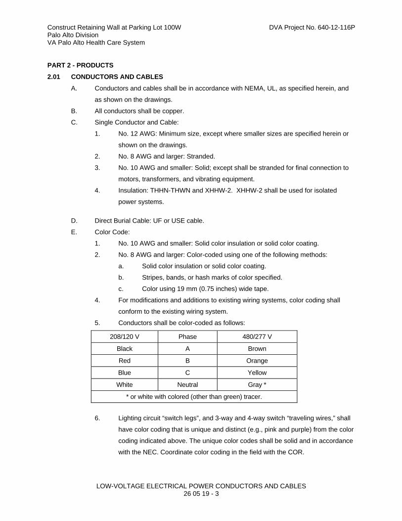
Construct Retaining Wall at Parking Lot 100W DVA Project No. 640-12-116P Palo Alto Division VA Palo Alto Health Care System
LOW-VOLTAGE ELECTRICAL POWER CONDUCTORS AND CABLES 26 05 19 - 3
PART 2 - PRODUCTS
2.01 CONDUCTORS AND CABLES
A. Conductors and cables shall be in accordance with NEMA, UL, as specified herein, and
as shown on the drawings.
B. All conductors shall be copper.
C. Single Conductor and Cable:
1. No. 12 AWG: Minimum size, except where smaller sizes are specified herein or
shown on the drawings.
2. No. 8 AWG and larger: Stranded.
3. No. 10 AWG and smaller: Solid; except shall be stranded for final connection to
motors, transformers, and vibrating equipment.
4. Insulation: THHN-THWN and XHHW-2. XHHW-2 shall be used for isolated
power systems.
D. Direct Burial Cable: UF or USE cable.
E. Color Code:
1. No. 10 AWG and smaller: Solid color insulation or solid color coating.
2. No. 8 AWG and larger: Color-coded using one of the following methods:
a. Solid color insulation or solid color coating.
b. Stripes, bands, or hash marks of color specified.
c. Color using 19 mm (0.75 inches) wide tape.
4. For modifications and additions to existing wiring systems, color coding shall
conform to the existing wiring system.
5. Conductors shall be color-coded as follows:
208/120 V Phase 480/277 V
Black A Brown
Red B Orange
Blue C Yellow
White Neutral Gray *
* or white with colored (other than green) tracer.
6. Lighting circuit “switch legs”, and 3-way and 4-way switch “traveling wires,” shall
have color coding that is unique and distinct (e.g., pink and purple) from the color
coding indicated above. The unique color codes shall be solid and in accordance
with the NEC. Coordinate color coding in the field with the COR.

Construct Retaining Wall at Parking Lot 100W DVA Project No. 640-12-116P Palo Alto Division VA Palo Alto Health Care System
LOW-VOLTAGE ELECTRICAL POWER CONDUCTORS AND CABLES 26 05 19 - 4
7. Color code for isolated power system wiring shall be in accordance with the NEC.
2.02 SPLICES
A. Splices shall be in accordance with NEC and UL.
B. Above Ground Splices for No. 10 AWG and Smaller:
1. Solderless, screw-on, reusable pressure cable type, with integral insulation,
approved for copper and aluminum conductors.
2. The integral insulator shall have a skirt to completely cover the stripped
conductors.
3. The number, size, and combination of conductors used with the connector, as
listed on the manufacturer's packaging, shall be strictly followed.
C. Above Ground Splices for No. 8 AWG to No. 4/0 AWG:
1. Compression, hex screw, or bolt clamp-type of high conductivity and
corrosion-resistant material, listed for use with copper and aluminum conductors.
2. Insulate with materials approved for the particular use, location, voltage, and
temperature. Insulation level shall be not less than the insulation level of the
conductors being joined.
3. Splice and insulation shall be product of the same manufacturer.
4. All bolts, nuts, and washers used with splices shall be zinc-plated steel.
D. Above Ground Splices for 250 kcmil and Larger:
1. Long barrel “butt-splice” or “sleeve” type compression connectors, with minimum
of two compression indents per wire, listed for use with copper and aluminum
conductors.
2. Insulate with materials approved for the particular use, location, voltage, and
temperature. Insulation level shall be not less than the insulation level of the
conductors being joined.
3. Splice and insulation shall be product of the same manufacturer.
E. Underground Splices for No. 10 AWG and Smaller:
1. Solderless, screw-on, reusable pressure cable type, with integral insulation.
Listed for wet locations, and approved for copper and aluminum conductors.
2. The integral insulator shall have a skirt to completely cover the stripped
conductors.
3. The number, size, and combination of conductors used with the connector, as
listed on the manufacturer's packaging, shall be strictly followed.
F. Underground Splices for No. 8 AWG and Larger:
1. Mechanical type, of high conductivity and corrosion-resistant material. Listed for
wet locations, and approved for copper and aluminum conductors.
Construct Retaining Wall at Parking Lot 100W DVA Project No. 640-12-116P Palo Alto Division VA Palo Alto Health Care System
LOW-VOLTAGE ELECTRICAL POWER CONDUCTORS AND CABLES 26 05 19 - 5
2. Insulate with materials approved for the particular use, location, voltage, and
temperature. Insulation level shall be not less than the insulation level of the
conductors being joined.
3. Splice and insulation shall be product of the same manufacturer.
G. Plastic electrical insulating tape: Per ASTM D2304, flame-retardant, cold and weather
resistant.
2.03 CONNECTORS AND TERMINATIONS
A. Mechanical type of high conductivity and corrosion-resistant material, listed for use with
copper and aluminum conductors.
B. Long barrel compression type of high conductivity and corrosion-resistant material, with
minimum of two compression indents per wire, listed for use with copper and aluminum
conductors.
C. All bolts, nuts, and washers used to connect connections and terminations to bus bars or
other termination points shall be zinc-plated steel.
2.04 CONTROL WIRING
A. Unless otherwise specified elsewhere in these specifications, control wiring shall be as
specified herein, except that the minimum size shall be not less than No. 14 AWG.
B. Control wiring shall be sized such that the voltage drop under in-rush conditions does not
adversely affect operation of the controls.
2.05 WIRE LUBRICATING COMPOUND
A. Lubricating compound shall be suitable for the wire insulation and conduit, and shall not
harden or become adhesive.
B. Shall not be used on conductors for isolated power systems.
PART 3 - EXECUTION
3.01 GENERAL
A. Install conductors in accordance with the NEC, as specified, and as shown on the
drawings.
B. Install all conductors in raceway systems.
C. Splice conductors only in outlet boxes, junction boxes, pullboxes, manholes, or
handholes.
D. Conductors of different systems (e.g., 120 V and 277 V) shall not be installed in the same
raceway.
E. Install cable supports for all vertical feeders in accordance with the NEC. Provide split
wedge type which firmly clamps each individual cable and tightens due to cable weight.

Construct Retaining Wall at Parking Lot 100W DVA Project No. 640-12-116P Palo Alto Division VA Palo Alto Health Care System
LOW-VOLTAGE ELECTRICAL POWER CONDUCTORS AND CABLES 26 05 19 - 6
F. In panelboards, cabinets, wireways, switches, enclosures, and equipment assemblies,
neatly form, train, and tie the conductors with non-metallic ties.
G. For connections to motors, transformers, and vibrating equipment, stranded conductors
shall be used only from the last fixed point of connection to the motors, transformers, or
vibrating equipment.
H. Use expanding foam or non-hardening duct-seal to seal conduits entering a building,
after installation of conductors.
I. Conductor and Cable Pulling:
1. Provide installation equipment that will prevent the cutting or abrasion of
insulation during pulling. Use lubricants approved for the cable.
2. Use nonmetallic pull ropes.
3. Attach pull ropes by means of either woven basket grips or pulling eyes attached
directly to the conductors.
4. All conductors in a single conduit shall be pulled simultaneously.
5. Do not exceed manufacturer’s recommended maximum pulling tensions and
sidewall pressure values.
J. No more than three branch circuits shall be installed in any one conduit.
K. When stripping stranded conductors, use a tool that does not damage the conductor or
remove conductor strands.
3.02 INSTALLATION IN MANHOLES
A. Train the cables around the manhole walls, but do not bend to a radius less than six
times the overall cable diameter.
B. Fireproofing:
1. Install fireproofing on low-voltage conductors where the low-voltage conductors
are installed in the same manholes with medium-voltage conductors.
2. Use fireproofing tape as specified in Section 26 05 13, MEDIUM-VOLTAGE
CABLES, and apply the tape in a single layer, half-lapped, or as recommended
by the manufacturer. Install the tape with the coated side towards the cable and
extend it not less than 25 mm (1 inch) into each duct.
3. Secure the fireproofing tape in place by a random wrap of glass cloth tape.
3.03 SPLICE AND TERMINATION INSTALLATION
A. Splices and terminations shall be mechanically and electrically secure, and tightened to
manufacturer’s published torque values using a torque screwdriver or wrench.
B. Where the Government determines that unsatisfactory splices or terminations have been
installed, replace the splices or terminations at no additional cost to the Government.

Construct Retaining Wall at Parking Lot 100W DVA Project No. 640-12-116P Palo Alto Division VA Palo Alto Health Care System
LOW-VOLTAGE ELECTRICAL POWER CONDUCTORS AND CABLES 26 05 19 - 7
3.04 CONDUCTOR IDENTIFICATION
A. When using colored tape to identify phase, neutral, and ground conductors larger than
No. 8 AWG, apply tape in half-overlapping turns for a minimum of 75 mm (3 inches) from
terminal points, and in junction boxes, pullboxes, and manholes. Apply the last two laps
of tape with no tension to prevent possible unwinding. Where cable markings are covered
by tape, apply tags to cable, stating size and insulation type.
3.05 FEEDER CONDUCTOR IDENTIFICATION
A. In each interior pullbox and each underground manhole and handhole, install brass tags
on all feeder conductors to clearly designate their circuit identification and voltage. The
tags shall be the embossed type, 40 mm (1-1/2 inches) in diameter and 40 mils thick.
Attach tags with plastic ties.
3.06 EXISTING CONDUCTORS
A. Unless specifically indicated on the plans, existing conductors shall not be reused.
3.07 CONTROL WIRING INSTALLATION
A. Unless otherwise specified in other sections, install control wiring and connect to
equipment to perform the required functions as specified or as shown on the drawings.
B. Install a separate power supply circuit for each system, except where otherwise shown
on the drawings.
3.08 CONTROL WIRING IDENTIFICATION
A. Install a permanent wire marker on each wire at each termination.
B. Identifying numbers and letters on the wire markers shall correspond to those on the
wiring diagrams used for installing the systems.
C. Wire markers shall retain their markings after cleaning.
D. In each manhole and handhole, install embossed brass tags to identify the system served
and function.
3.09 DIRECT BURIAL CABLE INSTALLATION
A. Tops of the cables:
1. Below the finished grade: Minimum 600 mm (24 inches) unless greater depth is
shown.
2. Below road and other pavement surfaces: In conduit as specified, minimum 760
mm (30 inches) unless greater depth is shown.
3. Do not install cables under railroad tracks.
B. Under road and paved surfaces: Install cables in concrete-encased galvanized steel rigid
conduits. Size as shown on plans, but not less than 50 mm (2 inches) trade size with

Construct Retaining Wall at Parking Lot 100W DVA Project No. 640-12-116P Palo Alto Division VA Palo Alto Health Care System
LOW-VOLTAGE ELECTRICAL POWER CONDUCTORS AND CABLES 26 05 19 - 8
bushings at each end of each conduit run. Provide size/quantity of conduits required to
accommodate cables plus one spare.
C. Work with extreme care near existing ducts, conduits, cables, and other utilities to
prevent any damage.
D. Excavation and backfill is specified in Section 31 20 00, EARTH MOVING. In addition:
1. Place 75 mm (3 inches) bedding sand in the trenches before installing the
cables.
2. Place 75 mm (3 inches) shading sand over the installed cables.
3. Install continuous horizontal 25 mm by 200 mm (1 inch x 8 inches) preservative-
impregnated wood planking 75 mm (3 inches) above the cables before
backfilling.
E. Provide horizontal slack in the cables for contraction during cold weather.
F. Install the cables in continuous lengths. Splices within cable runs shall not be accepted.
G. Connections and terminations shall be listed submersible-type designed for the cables
being installed.
H. Warning tape shall be continuously placed 300 mm (12 inches) above the buried cables.
3.10 ACCEPTANCE CHECKS AND TESTS
A. Perform in accordance with the manufacturer's recommendations. In addition, include
the following:
1. Visual Inspection and Tests: Inspect physical condition.
2. Electrical tests:
a. After installation but before connection to utilization devices, such as
fixtures, motors, or appliances, test conductors phase-to-phase and
phase-to-ground resistance with an insulation resistance tester. Existing
conductors to be reused shall also be tested.
b. Applied voltage shall be 500 V DC for 300 V rated cable, and 1000 V DC
for 600 V rated cable. Apply test for one minute or until reading is
constant for 15 seconds, whichever is longer. Minimum insulation
resistance values shall not be less than 25 megohms for 300 V rated
cable and 100 megohms for 600 V rated cable.
c. Perform phase rotation test on all three-phase circuits.
---END---

Construct Retaininng Wall at Parking Lot 100W DVA Project No. 640-12-116P Palo Alto Division VA Palo Alto Health Care System
GROUNDING AND BONDING FOR ELECTRICAL SYSTEMS
26 05 26 - 1
SECTION 26 05 26 GROUNDING AND BONDING FOR ELECTRICAL SYSTEMS
PART 1 - GENERAL
1.01 DESCRIPTION
A. This section specifies the furnishing, installation, connection, and testing of grounding
and bonding equipment, indicated as grounding equipment in this section.
B. “Grounding electrode system” refers to grounding electrode conductors and all electrodes
required or allowed by NEC, as well as made, supplementary, and lightning protection
system grounding electrodes.
C. The terms “connect” and “bond” are used interchangeably in this section and have the
same meaning.
1.02 RELATED WORK
A. Section 26 05 11, REQUIREMENTS FOR ELECTRICAL INSTALLATIONS:
Requirements that apply to all sections of Division 26.
B. Section 26 05 19, LOW-VOLTAGE ELECTRICAL POWER CONDUCTORS AND
CABLES: Low-voltage conductors.
C. Section 26 05 33, RACEWAY AND BOXES FOR ELECTRICAL SYSTEMS: Conduit and
boxes.
1.03 QUALITY ASSURANCE
A. Refer to Paragraph, QUALIFICATIONS (PRODUCTS AND SERVICES), in Section 26 05
11, REQUIREMENTS FOR ELECTRICAL INSTALLATIONS.
1.04 SUBMITTALS
A. Submit six copies of the following in accordance with Section 26 05 11,
REQUIREMENTS FOR ELECTRICAL INSTALLATIONS.
1. Shop Drawings:
a. Submit sufficient information to demonstrate compliance with drawings
and specifications.
b. Submit plans showing the location of system grounding electrodes and
connections, and the routing of aboveground and underground
grounding electrode conductors.
2. Test Reports:
a. Two weeks prior to the final inspection, submit ground resistance field
test reports to the COR.
3. Certifications:
a. Certification by the Contractor that the grounding equipment has been
properly installed and tested.
Construct Retaininng Wall at Parking Lot 100W DVA Project No. 640-12-116P Palo Alto Division VA Palo Alto Health Care System
GROUNDING AND BONDING FOR ELECTRICAL SYSTEMS
26 05 26 - 2
1.05 APPLICABLE PUBLICATIONS
A. Publications listed below (including amendments, addenda, revisions, supplements, and
errata) form a part of this specification to the extent referenced. Publications are
referenced in the text by designation only.
B. American Society for Testing and Materials (ASTM):
B1-07 ............................. Standard Specification for Hard-Drawn Copper Wire
B3-07 ............................. Standard Specification for Soft or Annealed Copper Wire
B8-11 ............................. Standard Specification for Concentric-Lay-Stranded Copper
Conductors, Hard, Medium-Hard, or Soft
C. Institute of Electrical and Electronics Engineers, Inc. (IEEE):
81-83 ............................. IEEE Guide for Measuring Earth Resistivity, Ground Impedance,
and Earth Surface Potentials of a Ground System Part 1: Normal
Measurements
D. National Fire Protection Association (NFPA):
70-11 ............................. National Electrical Code (NEC)
70E-12 ........................... National Electrical Safety Code
99-12 ............................. Health Care Facilities
E. Underwriters Laboratories, Inc. (UL):
44-10 ............................ Thermoset-Insulated Wires and Cables
83-08 ............................ Thermoplastic-Insulated Wires and Cables
467-07 .......................... Grounding and Bonding Equipment
PART 2 - PRODUCTS
2.01 GROUNDING AND BONDING CONDUCTORS
A. Equipment grounding conductors shall be insulated stranded copper, except that sizes
No. 10 AWG and smaller shall be solid copper. Insulation color shall be continuous green
for all equipment grounding conductors, except that wire sizes No. 4 AWG and larger
shall be identified per NEC.
B. Bonding conductors shall be bare stranded copper, except that sizes No. 10 AWG and
smaller shall be bare solid copper. Bonding conductors shall be stranded for final
connection to motors, transformers, and vibrating equipment.
C. Conductor sizes shall not be less than shown on the drawings, or not less than required
by the NEC, whichever is greater.
D. Insulation: THHN-THWN and XHHW-2. XHHW-2 shall be used for isolated power
systems.
2.02 GROUND RODS
A. copper clad steel 19 mm (0.75 inch) diameter by 3 M (10 feet) long.
Construct Retaininng Wall at Parking Lot 100W DVA Project No. 640-12-116P Palo Alto Division VA Palo Alto Health Care System
GROUNDING AND BONDING FOR ELECTRICAL SYSTEMS
26 05 26 - 3
B. Quantity of rods shall be as shown on the drawings, and as required to obtain the
specified ground resistance.
2.03 CONCRETE ENCASED ELECTRODE
A. Concrete encased electrode shall be No. 4 AWG bare copper wire, installed per NEC.
2.04 GROUND CONNECTIONS
A. Below Grade and Inaccessible Locations: Exothermic-welded type connectors.
B. Above Grade:
1. Bonding Jumpers: Listed for use with aluminum and copper conductors. For wire
sizes No. 8 AWG and larger, use compression-type connectors. For wire sizes
smaller than No. 8 AWG, use mechanical type lugs. Connectors or lugs shall
use zinc-plated steel bolts, nuts, and washers. Bolts shall be torqued to the
values recommended by the manufacturer.
PART 3 - EXECUTION
3.01 GENERAL
A. Install grounding equipment in accordance with the NEC, as shown on the drawings, and
as specified herein.
B. System Grounding:
1. Secondary service neutrals: Ground at the supply side of the secondary
disconnecting means and at the related transformer.
2. Separately derived systems (transformers downstream from the service
entrance): Ground the secondary neutral.
C. Equipment Grounding: Metallic piping, building structural steel, electrical enclosures,
raceways, junction boxes, outlet boxes, cabinets, machine frames, and other conductive
items in close proximity with electrical circuits, shall be bonded and grounded.
D. For patient care area electrical power system grounding, conform to NFPA 99 and NEC.
3.02 INACCESSIBLE GROUNDING CONNECTIONS
A. Make grounding connections, which are normally buried or otherwise inaccessible, by
exothermic weld.
3.03 MEDIUM-VOLTAGE EQUIPMENT AND CIRCUITS
A. Switchgear: Provide a bare grounding electrode conductor from the switchgear ground
bus to the grounding electrode system.
B. Duct Banks and Manholes: Provide an insulated equipment grounding conductor in each
duct containing medium-voltage conductors, sized per NEC except that minimum size
shall be No. 2 AWG. Bond the equipment grounding conductors to the switchgear ground
bus, to all manhole grounding provisions and hardware, to the cable shield grounding

Construct Retaininng Wall at Parking Lot 100W DVA Project No. 640-12-116P Palo Alto Division VA Palo Alto Health Care System
GROUNDING AND BONDING FOR ELECTRICAL SYSTEMS
26 05 26 - 4
provisions of medium-voltage cable splices and terminations, and to equipment
enclosures.
C. Pad-Mounted Transformers:
1. Provide a driven ground rod and bond with a grounding electrode conductor to
the transformer grounding pad.
2. Ground the secondary neutral.
D. Lightning Arresters: Connect lightning arresters to the equipment ground bus or ground
rods as applicable.
3.04 SECONDARY VOLTAGE EQUIPMENT AND CIRCUITS
A. Main Bonding Jumper: Bond the secondary service neutral to the ground bus in the
service equipment.
B. Metallic Piping, Building Structural Steel, and Supplemental Electrode(s):
1. Provide a grounding electrode conductor sized per NEC between the service
equipment ground bus and all metallic water pipe systems, building structural
steel, and supplemental or made electrodes. Provide jumpers across insulating
joints in the metallic piping.
2. Provide a supplemental ground electrode as shown on the drawings and bond to
the grounding electrode system.
3.05 RACEWAY
A. Conduit Systems:
1. Ground all metallic conduit systems. All metallic conduit systems shall contain an
equipment grounding conductor.
2. Non-metallic conduit systems, except non-metallic feeder conduits that carry a
grounded conductor from exterior transformers to interior or building-mounted
service entrance equipment, shall contain an equipment grounding conductor.
3. Metallic conduit that only contains a grounding conductor, and is provided for its
mechanical protection, shall be bonded to that conductor at the entrance and exit
from the conduit.
4. Metallic conduits which terminate without mechanical connection to an electrical
equipment housing by means of locknut and bushings or adapters, shall be
provided with grounding bushings. Connect bushings with a equipment
grounding conductor to the equipment ground bus.
B. Feeders and Branch Circuits: Install equipment grounding conductors with all feeders,
and power and lighting branch circuits.
C. Boxes, Cabinets, Enclosures, and Panelboards:
Construct Retaininng Wall at Parking Lot 100W DVA Project No. 640-12-116P Palo Alto Division VA Palo Alto Health Care System
GROUNDING AND BONDING FOR ELECTRICAL SYSTEMS
26 05 26 - 5
1. Bond the equipment grounding conductor to each pullbox, junction box, outlet
box, device box, cabinets, and other enclosures through which the conductor
passes (except for special grounding systems for intensive care units and other
critical units shown).
2. Provide lugs in each box and enclosure for equipment grounding conductor
termination.
D. Wireway Systems:
1. Bond the metallic structures of wireway to provide electrical continuity throughout
the wireway system, by connecting a No. 6 AWG bonding jumper at all
intermediate metallic enclosures and across all section junctions.
2. Install insulated No. 6 AWG bonding jumpers between the wireway system,
bonded as required above, and the closest building ground at each end and
approximately every 16 M (50 feet).
3. Use insulated No. 6 AWG bonding jumpers to ground or bond metallic wireway at
each end for all intermediate metallic enclosures and across all section junctions.
4. Use insulated No. 6 AWG bonding jumpers to ground cable tray to column-
mounted building ground plates (pads) at each end and approximately every 15
M (49 feet).
E. Receptacles shall not be grounded through their mounting screws. Ground receptacles
with a jumper from the receptacle green ground terminal to the device box ground screw
and a jumper to the branch circuit equipment grounding conductor.
F. Ground lighting fixtures to the equipment grounding conductor of the wiring system.
Fixtures connected with flexible conduit shall have a green ground wire included with the
power wires from the fixture through the flexible conduit to the first outlet box.
G. Fixed electrical appliances and equipment shall be provided with a ground lug for
termination of the equipment grounding conductor.
H. Raised Floors: Provide bonding for all raised floor components as shown on the
drawings.
I. Panelboard Bonding in Patient Care Areas: The equipment grounding terminal buses of
the normal and essential branch circuit panel boards serving the same individual patient
vicinity shall be bonded together with an insulated continuous copper conductor not less
than No. 10 AWG, installed in rigid metal conduit.
3.06 CORROSION INHIBITORS
A. When making grounding and bonding connections, apply a corrosion inhibitor to all
contact surfaces. Use corrosion inhibitor appropriate for protecting a connection between
the metals used.

Construct Retaininng Wall at Parking Lot 100W DVA Project No. 640-12-116P Palo Alto Division VA Palo Alto Health Care System
GROUNDING AND BONDING FOR ELECTRICAL SYSTEMS
26 05 26 - 6
3.07 CONDUCTIVE PIPING
A. Bond all conductive piping systems, interior and exterior, to the grounding electrode
system. Bonding connections shall be made as close as practical to the equipment
ground bus.
B. In operating rooms and at intensive care and coronary care type beds, bond the medical
gas piping and medical vacuum piping at the outlets directly to the patient ground bus.
3.08 EXTERIOR LIGHT POLES
A. Provide 6.1 M (20 feet) of No. 4 AWG bare copper coiled at bottom of pole base
excavation prior to pour, plus additional unspliced length in and above foundation as
required to reach pole ground stud.
3.09 GROUND RESISTANCE
A. Grounding system resistance to ground shall not exceed 5 ohms. Make any modifications
or additions to the grounding electrode system necessary for compliance without
additional cost to the Government. Final tests shall ensure that this requirement is met.
B. Grounding system resistance shall comply with the electric utility company ground
resistance requirements.
3.10 GROUND ROD INSTALLATION
A. For outdoor installations, drive each rod vertically in the earth, until top of rod is 610 mm
(24 inches) below final grade.
B. For indoor installations, leave 100 mm (4 inches) of each rod exposed.
C. Where buried or permanently concealed ground connections are required, make the
connections by the exothermic process, to form solid metal joints. Make accessible
ground connections with mechanical pressure-type ground connectors.
D. Where rock or impenetrable soil prevents the driving of vertical ground rods, install
angled ground rods or grounding electrodes in horizontal trenches to achieve the
specified ground resistance.
3.11 ACCEPTANCE CHECKS AND TESTS
A. Resistance of the grounding electrode system shall be measured using a four-terminal
fall-of-potential method as defined in IEEE 81. Ground resistance measurements shall be
made before the electrical distribution system is energized or connected to the electric
utility company ground system, and shall be made in normally dry conditions not fewer
than 48 hours after the last rainfall.
B. Resistance measurements of separate grounding electrode systems shall be made
before the systems are bonded together. The combined resistance of separate systems
may be used to meet the required resistance, but the specified number of electrodes
must still be provided.

Construct Retaininng Wall at Parking Lot 100W DVA Project No. 640-12-116P Palo Alto Division VA Palo Alto Health Care System
GROUNDING AND BONDING FOR ELECTRICAL SYSTEMS
26 05 26 - 7
C. Below-grade connections shall be visually inspected by the COR prior to backfilling. The
Contractor shall notify the COR 24 hours before the connections are ready for inspection.
---END---
Construct Retaining Wall at Parking Lot 100W DVA Project No. 640-12-116P Palo Alto Division VA Palo Alto Health Care System
RACEWAY AND BOXES FOR ELECTRICAL SYSTEMS 26 05 33 - 1
SECTION 26 05 33 RACEWAY AND BOXES FOR ELECTRICAL SYSTEMS
PART 1 - GENERAL
1.01 DESCRIPTION
A. This section specifies the furnishing, installation, and connection of conduit, fittings, and
boxes to form complete, coordinated, grounded raceway systems. Raceways are
required for all wiring unless shown or specified otherwise.
B. Definitions: The term conduit, as used in this specification, shall mean any or all of the
raceway types specified.
1.02 RELATED WORK
A. Mounting board for telephone closets: Section 06 10 00, ROUGH CARPENTRY.
B. Sealing around conduit penetrations through the building envelope to prevent moisture
migration into the building: Section 07 92 00, JOINT SEALANTS.
C. Identification and painting of conduit and other devices: Section 09 91 00, PAINTING.
D. General electrical requirements and items that is common to more than one section of
Division 26: Section 26 05 11, REQUIREMENTS FOR ELECTRICAL INSTALLATIONS.
E. Requirements for personnel safety and to provide a low impedance path for possible
ground fault currents: Section 26 05 26, GROUNDING AND BONDING FOR
ELECTRICAL SYSTEMS.
1.03 SUBMITTALS
In accordance with Section 01 33 23, SHOP DRAWINGS, PRODUCT DATA, AND SAMPLES,
furnish the following:
A. Shop Drawings:
1. Size and location of pull boxes
2. Layout of required conduit penetrations through structural elements.
4. The specific item proposed and its area of application shall be identified on the
catalog cuts.
B. Certification: Prior to final inspection, deliver to the COR four copies of the certification
that the material is in accordance with the drawings and specifications and has been
properly installed.
1.04 APPLICABLE PUBLICATIONS
A. Publications listed below (including amendments, addenda, revisions, supplements and
errata) form a part of this specification to the extent referenced. Publications are
referenced in the text by the basic designation only.
B. National Fire Protection Association (NFPA):
70-05 ............................. National Electrical Code (NEC)

Construct Retaining Wall at Parking Lot 100W DVA Project No. 640-12-116P Palo Alto Division VA Palo Alto Health Care System
RACEWAY AND BOXES FOR ELECTRICAL SYSTEMS 26 05 33 - 2
C. Underwriters Laboratories, Inc. (UL):
6-03 ............................... Rigid Metal Conduit
50-03 ............................. Enclosures for Electrical Equipment
360-03 ........................... Liquid-Tight Flexible Steel Conduit
467-01 ........................... Grounding and Bonding Equipment
514A-01 ......................... Metallic Outlet Boxes
514B-02 ......................... Fittings for Cable and Conduit
797-03 ........................... Electrical Metallic Tubing
1242-00 ......................... Intermediate Metal Conduit
D. National Electrical Manufacturers Association (NEMA):
TC-3-04 ......................... PVC Fittings for Use with Rigid PVC Conduit and Tubing
FB1-03 .......................... Fittings, Cast Metal Boxes and Conduit Bodies for Conduit,
Electrical Metallic Tubing and Cable
PART 2 - PRODUCTS
2.01 MATERIAL
A. Conduit Size: In accordance with the NEC, but not less than 19 mm (3/4 inch) unless
otherwise shown. Where permitted by the NEC, 19 mm (3/4 inch) flexible conduit may be
used for tap connections to recessed lighting fixtures.
B. Conduit:
1. Rigid galvanized steel: Shall Conform to UL 6, ANSI C80.1.
2. Rigid intermediate steel conduit (IMC): Shall Conform to UL 1242, ANSI C80.6.
3. Electrical metallic tubing (EMT): Shall Conform to UL 797, ANSI C80.3.
Maximum size not to exceed 105 mm (4 inch) and shall be permitted only with
cable rated 600 volts or less.
4. Flexible galvanized steel conduit: Shall Conform to UL 1.
5. Liquid-tight flexible metal conduit: Shall Conform to UL 360.
C. Conduit Fittings:
1. Rigid steel and IMC conduit fittings:
a. Fittings shall meet the requirements of UL 514B and ANSI/ NEMA FB1.
b. Standard threaded couplings, locknuts, bushings, and elbows: Only steel
or malleable iron materials are acceptable. Integral retractable type IMC
couplings are also acceptable.
c. Locknuts: Bonding type with sharp edges for digging into the metal wall
of an enclosure.
Construct Retaining Wall at Parking Lot 100W DVA Project No. 640-12-116P Palo Alto Division VA Palo Alto Health Care System
RACEWAY AND BOXES FOR ELECTRICAL SYSTEMS 26 05 33 - 3
d. Bushings: Metallic insulating type, consisting of an insulating insert
molded or locked into the metallic body of the fitting. Bushings made
entirely of metal or nonmetallic material are not permitted.
e. Erickson (union-type) and set screw type couplings: Approved for use in
concrete are permitted for use to complete a conduit run where conduit
is installed in concrete. Use set screws of case hardened steel with hex
head and cup point to firmly seat in conduit wall for positive ground.
Tightening of set screws with pliers is prohibited.
f. Sealing fittings: Threaded cast iron type. Use continuous drain type
sealing fittings to prevent passage of water vapor. In concealed work,
install fittings in flush steel boxes with blank cover plates having the
same finishes as that of other electrical plates in the room.
3. Electrical metallic tubing fittings:
a. Fittings shall meet the requirements of UL 514B and ANSI/ NEMA FB1.
b. Only steel or malleable iron materials are acceptable.
c. Couplings and connectors: Concrete tight and rain tight, with connectors
having insulated throats. Use gland and ring compression type couplings
and connectors for conduit sizes 50 mm (2 inches) and smaller. Use set
screw type couplings with four set screws each for conduit sizes over 50
mm (2 inches). Use set screws of case-hardened steel with hex head
and cup point to firmly seat in wall of conduit for positive grounding.
d. Indent type connectors or couplings are prohibited.
e. Die-cast or pressure-cast zinc-alloy fittings or fittings made of "pot metal"
are prohibited.
4. Flexible steel conduit fittings:
a. Conform to UL 514B. Only steel or malleable iron materials are
acceptable.
b. Clamp type, with insulated throat.
5. Liquid-tight flexible metal conduit fittings:
a. Fittings shall meet the requirements of UL 514B and ANSI/ NEMA FB1.
b. Only steel or malleable iron materials are acceptable.
c. Fittings must incorporate a threaded grounding cone, a steel or plastic
compression ring, and a gland for tightening. Connectors shall have
insulated throats.
6. Direct burial plastic conduit fittings:
a. Fittings shall meet the requirements of UL 514C and NEMA TC3.
b. As recommended by the conduit manufacturer.

Construct Retaining Wall at Parking Lot 100W DVA Project No. 640-12-116P Palo Alto Division VA Palo Alto Health Care System
RACEWAY AND BOXES FOR ELECTRICAL SYSTEMS 26 05 33 - 4
7. Surface metal raceway fittings: As recommended by the raceway manufacturer.
8. Expansion and deflection couplings:
a. Conform to UL 467 and UL 514B.
b. Accommodate, 19 mm (0.75 inch) deflection, expansion, or contraction
in any direction, and allow 30 degree angular deflections.
c. Include internal flexible metal braid sized to guarantee conduit ground
continuity and fault currents in accordance with UL 467, and the NEC
code tables for ground conductors.
d. Jacket: Flexible, corrosion-resistant, watertight, moisture and heat
resistant molded rubber material with stainless steel jacket clamps.
D. Conduit Supports:
1. Parts and hardware: Zinc-coat or provide equivalent corrosion protection.
2. Individual Conduit Hangers: Designed for the purpose, having a pre-assembled
closure bolt and nut, and provisions for receiving a hanger rod.
3. Multiple conduit (trapeze) hangers: Not less than 38 mm by 38 mm (1-1/2 by
1-1/2 inch), 12 gage steel, cold formed, lipped channels; with not less than 9 mm
(3/8 inch) diameter steel hanger rods.
E. Outlet, Junction, and Pull Boxes:
1. UL-50 and UL-514A.
2. Cast metal where required by the NEC or shown, and equipped with rustproof
boxes.
3. Sheet metal boxes: Galvanized steel, except where otherwise shown.
4. Flush mounted wall or ceiling boxes shall be installed with raised covers so that
front face of raised cover is flush with the wall. Surface mounted wall or ceiling
boxes shall be installed with surface style flat or raised covers.
F. Wireways: Equip with hinged covers, except where removable covers are shown.
G. Warning Tape: Standard, 4-Mil polyethylene 76 mm (3 inch) wide tape detectable type,
red with black letters, and imprinted with “CAUTION BURIED ELECTRIC LINE BELOW”.
PART 3 - EXECUTION
3.01 PENETRATIONS
A. Cutting or Holes:
1. Locate holes in advance where they are proposed in the structural sections such
as ribs or beams. Obtain the approval of the COR prior to drilling through
structural sections.
B. Fire Stop: Where conduits, wireways, and other electrical raceways pass through fire
partitions, fire walls, smoke partitions, or floors, install a fire stop that provides an
Construct Retaining Wall at Parking Lot 100W DVA Project No. 640-12-116P Palo Alto Division VA Palo Alto Health Care System
RACEWAY AND BOXES FOR ELECTRICAL SYSTEMS 26 05 33 - 5
effective barrier against the spread of fire, smoke and gases as specified in Section 07
84 00, FIRESTOPPING, with rock wool fiber or silicone foam sealant only. Completely fill
and seal clearances between raceways and openings with the fire stop material.
C. Waterproofing: At floor, exterior wall, and roof conduit penetrations, completely seal
clearances around the conduit and make watertight as specified in Section 07 92 00,
JOINT SEALANTS.
3.02 INSTALLATION, GENERAL
A. In accordance with UL, NEC, as shown, and as hereinafter specified.
B. Essential (Emergency) raceway systems shall be entirely independent of other raceway
systems, except where specifically "accepted" by NEC Article 517.
C. Install conduit as follows:
1. In complete runs before pulling in cables or wires.
2. Flattened, dented, or deformed conduit is not permitted. Remove and replace the
damaged conduits with new undamaged material.
3. Assure conduit installation does not encroach into the ceiling height head room,
walkways, or doorways.
4. Cut square with a hacksaw, ream, remove burrs, and draw up tight.
5. Mechanically and electrically continuous.
6. Independently support conduit at 8’0” on center. Do not use other supports i.e.,
(suspended ceilings, suspended ceiling supporting members, lighting fixtures,
conduits, mechanical piping, or mechanical ducts).
7. Support within 300 mm (1 foot) of changes of direction, and within 300 mm (1
foot) of each enclosure to which connected.
8. Close ends of empty conduit with plugs or caps at the rough-in stage to prevent
entry of debris, until wires are pulled in.
9. Conduit installations under fume and vent hoods are prohibited.
10. Secure conduits to cabinets, junction boxes, pull boxes and outlet boxes with
bonding type locknuts. For rigid and IMC conduit installations, provide a locknut
on the inside of the enclosure, made up wrench tight. Do not make conduit
connections to junction box covers.
11. Do not use aluminum conduits in wet locations.
12. Unless otherwise indicated on the drawings or specified herein, all conduits shall
be installed concealed within finished walls, floors and ceilings.
D. Conduit Bends:
1. Make bends with standard conduit bending machines.
2. Conduit hickey may be used for slight offsets, and for straightening stubbed out
conduits.

Construct Retaining Wall at Parking Lot 100W DVA Project No. 640-12-116P Palo Alto Division VA Palo Alto Health Care System
RACEWAY AND BOXES FOR ELECTRICAL SYSTEMS 26 05 33 - 6
3. Bending of conduits with a pipe tee or vise is prohibited.
E. Layout and Homeruns:
1. Install conduit with wiring, including homeruns, as shown.
2. Deviations: Make only where necessary to avoid interferences and only after
drawings showing the proposed deviations have been submitted approved by the
COR.
3.03 CONCEALED WORK INSTALLATION
A. Furred or Suspended Ceilings and in Walls:
1. Conduit for conductors above 600 volts:
a. Rigid steel or rigid aluminum.
b. Aluminum conduit mixed indiscriminately with other types in the same
system is prohibited.
2. Conduit for conductors 600 volts and below:
a. Rigid steel, IMC, rigid aluminum, or EMT. Different type conduits mixed
indiscriminately in the same system is prohibited.
3. Align and run conduit parallel or perpendicular to the building lines.
4. Connect recessed lighting fixtures to conduit runs with maximum 1800 mm (six
feet) of flexible metal conduit extending from a junction box to the fixture.
5. Tightening set screws with pliers is prohibited.
3.04 EXPOSED WORK INSTALLATION
A. Unless otherwise indicated on the drawings, exposed conduit is only permitted in
mechanical and electrical rooms.
B. Conduit for conductors above 600 volts:
1. Rigid steel or rigid aluminum.
2. Aluminum conduit mixed indiscriminately with other types in the same
system is prohibited.
C. Conduit for Conductors 600 volts and below:
1. Rigid steel, IMC, rigid aluminum, or EMT. Different type of conduits
mixed indiscriminately in the system is prohibited.
D. Align and run conduit parallel or perpendicular to the building lines.
E. Install horizontal runs close to the ceiling or beams and secure with conduit
straps.
F. Support horizontal or vertical runs at not over 2400 mm (eight foot) intervals.
G. Surface metal raceways: Use only where shown.
H. Painting:
1. Paint exposed conduit as specified in Section 09 91 00, PAINTING.

Construct Retaining Wall at Parking Lot 100W DVA Project No. 640-12-116P Palo Alto Division VA Palo Alto Health Care System
RACEWAY AND BOXES FOR ELECTRICAL SYSTEMS 26 05 33 - 7
2. Paint all conduits containing cables rated over 600 volts safety orange.
Refer to Section 09 91 00, PAINTING for preparation, paint type, and
exact color. In addition, paint legends, using 50 mm (two inch) high black
numerals and letters, showing the cable voltage rating. Provide legends
where conduits pass through walls and floors and at maximum 6000 mm
(20 foot) intervals in between.
3.05 DIRECT BURIAL INSTALLATION
A. Exterior routing of Lighting Systems and Other Branch circuits (600 Volt and Less, and
1500 mm (5 feet) from the buildings):
1. Conduit: Thick wall PVC or high density PE, unless otherwise shown.
2. Mark conduit at uniform intervals to show the kind of material, direct burial type,
and the UL approval label.
3. Install conduit fittings and terminations as recommended by the conduit
manufacturer.
4. Tops of conduits shall be as follows unless otherwise shown:
a. Not less than 600 mm (24 inches) below finished grade.
b. Not less than 750 mm (30 inches) below road and other paved surfaces.
5. Work with extreme care near existing ducts, conduits, cables, and other utilities
to avoid damaging them.
6. Seal conduits, including spare conduits, at building entrances and at outdoor
terminations for equipment with a suitable compound that prevents the entrance
of moisture and gases.
7. Where metal conduit is shown, install threaded heavy wall rigid steel galvanized
conduit or type A20 rigid steel galvanized conduit coated with .5 mm (20 mil)
bonded PVC, or rigid steel or IMC, PVC coated or standard coated with
bituminous asphaltic compound.
8. Warning tape shall be continuously placed 300 mm (12 inches) above conduits
or electric lines.
3.06 HAZARDOUS LOCATIONS
A. Use rigid steel conduit only, notwithstanding requirements otherwise specified in this or
other sections of these specifications.
B. Install UL approved sealing fittings, that prevent passage of explosive vapors, in
hazardous areas equipped with explosive proof lighting fixtures, switches, and
receptacles, as required by the NEC.
3.07 WET OR DAMP LOCATIONS
A. Unless otherwise shown, use conduits of rigid steel or IMC.

Construct Retaining Wall at Parking Lot 100W DVA Project No. 640-12-116P Palo Alto Division VA Palo Alto Health Care System
RACEWAY AND BOXES FOR ELECTRICAL SYSTEMS 26 05 33 - 8
B. Provide sealing fittings, to prevent passage of water vapor, where conduits pass from
warm to cold locations, i.e., (refrigerated spaces, constant temperature rooms, air
conditioned spaces building exterior walls, roofs) or similar spaces.
C. Unless otherwise shown, use rigid steel or IMC conduit within 1500 mm (5 feet) of the
exterior and below concrete building slabs in contact with soil, gravel, or vapor barriers.
Conduit shall include an outer factory coating of .5 mm (20 mil) bonded PVC or field coat
with asphaltum before installation. After installation, completely coat damaged areas of
coating.
3.08 MOTORS AND VIBRATING EQUIPMENT
A. Use flexible metal conduit for connections to motors and other electrical equipment
subject to movement, vibration, misalignment, cramped quarters, or noise transmission.
B. Provide liquid-tight flexible metal conduit for installation in exterior locations, moisture or
humidity laden atmosphere, corrosive atmosphere, water or spray wash-down
operations, inside (air stream) of HVAC units, and locations subject to seepage or
dripping of oil, grease or water. Provide a green ground wire with flexible metal conduit.
3.09 EXPANSION JOINTS
A. Conduits 75 mm (3 inches) and larger, that are secured to the building structure on
opposite sides of a building expansion joint, require expansion and deflection couplings.
Install the couplings in accordance with the manufacturer's recommendations.
B. Provide conduits smaller than 75 mm (3 inches) with junction boxes on both sides of the
expansion joint. Connect conduits to junction boxes with sufficient slack of flexible
conduit to produce 125 mm (5 inch) vertical drop midway between the ends. Flexible
conduit shall have a copper green ground bonding jumper installed. In lieu of this flexible
conduit, expansion and deflection couplings as specified above for 375 mm (15 inches)
and larger conduits are acceptable.
C. Install expansion and deflection couplings where shown.
D. Seismic Areas: In seismic areas, provide conduits rigidly secured to the building structure
on opposite sides of a building expansion joint with junction boxes on both sides of the
joint. Connect conduits to junction boxes with 375 mm (15 inches) of slack flexible
conduit. Flexible conduit shall have a copper green ground bonding jumper installed.//
3.10 CONDUIT SUPPORTS, INSTALLATION
A. Safe working load shall not exceed 1/4 of proof test load of fastening devices.
B. Use pipe straps or individual conduit hangers for supporting individual conduits.
Maximum distance between supports is 2.5 m (8 foot) on center.
C. Support multiple conduit runs with trapeze hangers. Use trapeze hangers that are
designed to support a load equal to or greater than the sum of the weights of the
Construct Retaining Wall at Parking Lot 100W DVA Project No. 640-12-116P Palo Alto Division VA Palo Alto Health Care System
RACEWAY AND BOXES FOR ELECTRICAL SYSTEMS 26 05 33 - 9
conduits, wires, hanger itself, and 90 kg (200 pounds). Attach each conduit with U-bolts
or other approved fasteners.
D. Support conduit independently of junction boxes, pull boxes, fixtures, suspended ceiling
T-bars, angle supports, and similar items.
E. Bolts supported only by plaster or gypsum wallboard are not acceptable.
F. Metal Structures: Use machine screw fasteners or other devices specifically designed
and approved for the application.
G. Attachment by wood plugs, rawl plug, plastic, lead or soft metal anchors, or wood
blocking and bolts supported only by plaster is prohibited.
H. Chain, wire, or perforated strap shall not be used to support or fasten conduit.
I. Spring steel type supports or fasteners are prohibited for all uses except: Horizontal and
vertical supports/fasteners within walls.
J. Vertical Supports: Vertical conduit runs shall have riser clamps and supports in
accordance with the NEC and as shown. Provide supports for cable and wire with fittings
that include internal wedges and retaining collars.
3.11 BOX INSTALLATION
A. Boxes for Concealed Conduits:
1. Flush mounted.
2. Provide raised covers for boxes to suit the wall or ceiling, construction and finish.
B. In addition to boxes shown, install additional boxes where needed to prevent damage to
cables and wires during pulling in operations.
C. Remove only knockouts as required and plug unused openings. Use threaded plugs for
cast metal boxes and snap-in metal covers for sheet metal boxes.
D. Outlet boxes in the same wall mounted back-to-back are prohibited. A minimum 600 mm
(24 inch), center-to-center lateral spacing shall be maintained between boxes.)
E. Minimum size of outlet boxes for ground fault interrupter (GFI) receptacles is 100 mm (4
inches) square by 55 mm (2-1/8 inches) deep, with device covers for the wall material
and thickness involved.
F. Stencil or install phenolic nameplates on covers of the boxes identified on riser diagrams;
for example "SIG-FA JB No. 1".
G. On all Branch Circuit junction box covers, identify the circuits with black marker.
--- END ---

Construct Retaining Wall at Parking Lot 100W DVA Project No. 640-12-116P Palo Alto Division VA Palo Alto Health Care System
26 05 41 - 1
SECTION 26 05 41 UNDERGROUND ELECTRICAL CONSTRUCTION
PART 1 - GENERAL
1.1 DESCRIPTION
A. This section specifies the furnishing, installation, and connection of precast manholes and
pullboxes with ducts to form a complete underground raceway system.
B. “Duct” and “conduit,” and “rigid metal conduit” and “rigid steel conduit” are used interchangeably
in this specification.
1.2 RELATED WORK
A. Section 07 92 00, JOINT SEALANTS: Sealing of conduit penetrations.
B. Section 26 05 11, REQUIREMENTS FOR ELECTRICAL INSTALLATIONS: General electrical
requirements and items that are common to more than one section of Division 26.
C. Section 26 05 26, GROUNDING AND BONDING FOR ELECTRICAL SYSTEMS: Requirements
for personnel safety and to provide a low impedance path for possible ground fault currents.
D. Section 26 05 33, RACEWAY AND BOXES FOR ELECTRICAL SYSTEMS: Conduits, fittings and
boxes for raceway systems.
1.3 QUALITY ASSURANCE
A. Refer to Paragraph, QUALIFICATIONS, in Section 26 05 11, REQUIREMENTS FOR
ELECTRICAL INSTALLATIONS.
B. Coordinate layout and installation of ducts, manholes, pullboxes, and pull-boxes with final
arrangement of other utilities, site grading, and surface features, as determined in the field.
1.4 SUBMITTALS
A. Submit in accordance with Section 26 05 11, REQUIREMENTS FOR ELECTRICAL
INSTALLATIONS.
B. Shop Drawings:
1. Clearly present sufficient information to determine compliance with drawings and
specifications.
2. Include manholes, pullboxes, duct materials, and hardware. Submit plan and elevation
drawings, showing openings, pulling irons, cable supports, cover, ladder, sump, and other
accessories and details.
3. Proposed deviations from details on the drawings shall be clearly marked on the submittals. If it
is necessary to locate manholes or pullboxes at locations other than shown on the drawings,
show the proposed locations accurately on scaled site drawings, and submit four copies to
the COTR for approval prior to construction.
C. Certifications: Two weeks prior to the final inspection, submit four copies of the following
certifications to the COTR:
Construct Retaining Wall at Parking Lot 100W DVA Project No. 640-12-116P Palo Alto Division VA Palo Alto Health Care System
26 05 41 - 2
1. Certification by the manufacturer that the materials conform to the requirements of the
drawings and specifications.
2. Certification by the contractor that the materials have been properly installed, connected, and
tested.
1.5 APPLICABLE PUBLICATIONS
A. Publications listed below (including amendments, addenda, revisions, supplements, and errata)
form a part of this specification to the extent referenced. Publications are referenced in the text by
designation only.
B. American Concrete Institute (ACI):
Building Code Requirements for Structural Concrete
318/318M-05 .............................. Building Code Requirements for Structural Concrete &
Commentary
SP-66-04 .................................... ACI Detailing Manual
C. American National Standards Institute (ANSI):
77-07 .......................................... Underground Enclosure Integrity
D. American Society for Testing and Materials (ASTM):
C478-09 ..................................... Standard Specification for Precast Reinforced Concrete Manhole
Sections
C858-09 ..................................... Underground Precast Concrete Utility Structures
C990-09 ..................................... Standard Specification for Joints for Concrete Pipe, Manholes
and Precast Box Sections Using Preformed Flexible Joint
Sealants.
E. Institute of Electrical and Electronic Engineers (IEEE):
C2-07 ....................................... National Electrical Safety Code
F. National Electrical Manufacturers Association (NEMA):
TC 2-03 ...................................... Electrical Polyvinyl Chloride (PVC) Tubing And Conduit
TC 3-2004 .................................. PVC Fittings for Use With Rigid PVC Conduit And Tubing
TC 6 & 8 2003 ............................ PVC Plastic Utilities Duct For Underground Installations
TC 9-2004 .................................. Fittings For PVC Plastic Utilities Duct For Underground
Installation
G. National Fire Protection Association (NFPA):
70-08 .......................................... National Electrical Code (NEC)
H. Underwriters Laboratories, Inc. (UL):
6-07 ............................................ Electrical Rigid Metal Conduit-Steel
467-07 ........................................ Grounding and Bonding Equipment
651-05 ........................................ Schedule 40 and 80 Rigid PVC Conduit and Fittings
651A-00 ...................................... Type EB and A Rigid PVC Conduit and HDPE Conduit
Construct Retaining Wall at Parking Lot 100W DVA Project No. 640-12-116P Palo Alto Division VA Palo Alto Health Care System
26 05 41 - 3
651B-07 ...................................... Continuous Length HDPE Conduit
I. U.S. General Services Administration (GSA):
A-A-60005-1998 ......................... Frames, Covers, Gratings, Steps, Sump and Catch Basin,
Manhole
1.6 STORAGE
Lift and support pre-cast concrete structures only at designated lifting or supporting points.
PART 2 - PRODUCTS
2.1 PRE-CAST CONCRETE MANHOLES AND HARDWARE
A. Structure: Factory-fabricated, reinforced-concrete, monolithically-poured walls and bottom. Frame
and cover shall form top of manhole. Comply with ASTM C 858.
B. Cable Supports:
1. Cable stanchions shall be hot-rolled, heavy duty, hot-dipped galvanized "T" section steel,
2.25 in [56 mm] x 0.25 in [6 mm] in size, and punched with 14 holes on 1.5 in [38 mm]
centers for attaching cable arms.
2. Cable arms shall be 0.1875 in [5 mm] gauge, hot-rolled, hot-dipped galvanized sheet steel,
pressed to channel shape. Arms shall be approximately 2.5 in [63 mm] wide x 14 in [350 mm]
long.
3. Insulators for cable supports shall be high-glazed, wet process porcelain, and shall
completely encircle the cable.
4. Equip each cable stanchion with two spare cable arms and six spare insulators for future use.
D. Ground Rod Sleeve: Provide a 3 in [75 mm] PVC sleeve in manhole floors so that a driven
ground rod may be installed.
2.2 PULLBOXES
A. General: Size as indicated on drawings. Provide pullboxes with weatherproof, non-skid covers
with recessed hook eyes, secured with corrosion- and tamper-resistant hardware. Cover material
shall be identical to pullbox material. Covers shall have molded lettering, ELECTRIC or SIGNAL
as applicable. Pullboxes shall comply with the requirements of ANSI/SCTE 77 loading. Provide
pulling irons, 0.875 in [22 mm] diameter galvanized steel bar with exposed triangular-shaped
opening.
B. Concrete Pullboxes: Shall be monolithically-poured reinforced concrete.
2.3. DUCTS
A. Number and sizes shall be as shown on drawings.
B. Ducts (concrete-encased):

Construct Retaining Wall at Parking Lot 100W DVA Project No. 640-12-116P Palo Alto Division VA Palo Alto Health Care System
26 05 41 - 4
1. Plastic Duct:
a. UL 651 and 651A Schedule 40 PVC.
b. Duct shall be suitable for use with 194˚ F [90˚ C] rated conductors.
2. Conduit Spacers: Prefabricated plastic.
C. Ducts (direct-burial):
1. Plastic duct:
a. NEMA TC2 and TC3
b. UL 651, 651A, and 651B, Schedule 40 PVC or HDPE.
c. Duct shall be suitable for use with 167˚ F [75˚ C] rated conductors.
2. Rigid metal conduit: UL6 and NEMA RN1 galvanized rigid steel, threaded type, half-lapped
with 10 mil PVC tape.
2.4 GROUNDING
A. Rods: Per Section 26 05 26, GROUNDING AND BONDING FOR ELECTRICAL SYSTEMS.
B. Ground Wire: Stranded bare copper 6 AWG [16 mm²] minimum.
2.5 WARNING TAPE
Standard 4-mil polyethylene 3 in [76 mm] wide detectable tape, red with black letters, imprinted
with “CAUTION - BURIED ELECTRIC CABLE BELOW” or similar.
2.6 PULL ROPE FOR SPARE DUCTS
Plastic with 200 lb [890 N] minimum tensile strength.
PART 3 - EXECUTION
3.1 MANHOLE AND PULLBOX INSTALLATION
A. Assembly and installation shall follow the printed instructions and recommendations of the
manufacturer. Install manholes and pullboxes level and plumb.
1. Units shall be installed on a 12 in [300 mm] level bed of 90% compacted granular fill,
well-graded from the 1 in [25 mm] sieve to the No. 4 sieve. Granular fill shall be compacted
with a minimum of four passes with a plate compactor.
2. Seal duct terminations so they are watertight.
B. Access: Ensure the top of frames and covers are flush with finished grade.
C. Ground Rods in Manholes: Drive a ground rod into the earth, through the floor sleeve, after the
manhole is set in place. Fill the sleeve with sealant to make a watertight seal. Rods shall protrude
approximately 4 in [100 mm] above the manhole floor.
D. Grounding in Manholes:
1. Install a No. 3/0 AWG [95 mm²] bare copper ring grounding conductor around the inside
perimeter of the manhole and anchor to the walls with metallic cable clips.
2. Connect the ring grounding conductor to the ground rod by an exothermic welding process.
Construct Retaining Wall at Parking Lot 100W DVA Project No. 640-12-116P Palo Alto Division VA Palo Alto Health Care System
26 05 41 - 5
3. Bond the ring grounding conductor to the duct bank equipment grounding conductors, the
exposed non-current carrying metal parts of racks, sump covers, and like items in the
manholes with a minimum No. 6 AWG [16 mm²] bare copper jumper.
3.2 TRENCHING
A. Refer to EARTH MOVING for trenching, backfilling, and compaction.
B. Before performing trenching work at existing facilities, the Ground Penetrating Radar Survey shall
be carefully performed by certified technician to reveal all existing underground ducts, conduits,
cables, and other utility systems.
C. Work with extreme care near existing ducts, conduits, cables, and other utilities to avoid
damaging them.
D. Cut the trenches neatly and uniformly.
E. For Concrete-Encased Ducts:
1. After excavation of the trench, stakes shall be driven in the bottom of the trench at 4 ft [1.2 M]
intervals to establish the grade and route of the duct bank.
2. Pitch the trenches uniformly toward manholes or both ways from high points between
manholes for the required duct line drainage. Avoid pitching the ducts toward buildings
wherever possible.
3. The walls of the trench may be used to form the side walls of the duct bank, provided that the
soil is self-supporting and that concrete envelope can be poured without soil inclusions.
Forms are required where the soil is not self-supporting.
4. After the concrete-encased duct has sufficiently cured, the trench shall be backfilled to grade
with earth, and appropriate warning tape installed.
F. Conduits to be installed under existing paved areas and roads that cannot be disturbed shall be
jacked into place. Conduits shall be heavy wall rigid steel.
3.3 DUCT INSTALLATION
A. General Requirements:
1. Ducts shall be in accordance with the NEC and IEEE C2, as shown on the drawings, and as
specified.
2. Slope ducts to drain towards manholes and pullboxes, and away from building and
equipment entrances. Pitch not less than 4 in [100 mm] in 100 ft [30 M].
3. Underground conduit stub-ups and sweeps to equipment inside of buildings shall be taped
galvanized rigid steel, and shall extend a minimum of 5 ft [1.5 M] outside the building
foundation. Tops of conduits below building slab shall be minimum 24 in [610 mm] below
bottom of slab.
Construct Retaining Wall at Parking Lot 100W DVA Project No. 640-12-116P Palo Alto Division VA Palo Alto Health Care System
26 05 41 - 6
4. Stub-ups, sweeps, and risers to equipment mounted on outdoor concrete slabs shall be
taped galvanized rigid steel, and shall extend a minimum of 5 ft [1.5 M] away from the edge
of slab.
5. Install insulated grounding bushings on the terminations.
6. Radius for turns of direction shall be sufficient to accomplish pulls without damage. Minimum
radius shall be six times conduit diameter. Use manufactured long sweep bends.
7. Additional burial depth shall be required in order to accomplish NEC-required minimum bend
radius of ducts.
8. All multiple conduit runs shall have conduit spacers. Spacers shall securely support and
maintain uniform spacing of the duct assembly a minimum of 3 in [75 mm] above the bottom
of the trench during the concrete pour. Spacer spacing shall not exceed 5 ft [1.5 M]. Secure
spacers to ducts and earth to prevent floating during concrete pour. Provide nonferrous tie
wires to prevent displacement of the ducts during pouring of concrete. Tie wires shall not act
as substitute for spacers.
9. Duct lines shall be installed no less than 12 in [300 mm] from other utility systems, such as
water, sewer, and chilled water.
10. Clearances between individual ducts:
a. For like services, not less than 3 in [75 mm].
b. For power and signal services, not less than 6 in [150 mm].
11. Duct lines shall terminate at window openings in manhole walls as shown on the drawings.
All ducts shall be fitted with end bells.
12. Couple the ducts with proper couplings. Stagger couplings in rows and layers to ensure
maximum strength and rigidity of the duct bank.
13. Keep ducts clean of earth, sand, or gravel, and seal with tapered plugs upon completion of
each portion of the work.
14. Seal conduits, including spare conduits, at building entrances and at outdoor equipment
terminations with a suitable compound to prevent entrance of moisture and gases.
B. and Direct-Burial Duct and Conduit Identification: Place continuous strip of warning tape
approximately 12 in [300 mm] above ducts or conduits before backfilling trenches. Warning tape
shall be preprinted with proper identification.
C. Spare Ducts and Conduits: Where spare ducts are shown, they shall have a nylon pull rope
installed. They shall be capped at each end and labeled as to location of the other end.
D. Duct and Conduit Cleaning:
1. Upon completion of the duct installation, a standard flexible mandrel shall be pulled through
each duct to loosen particles of earth, sand, or foreign material left in the duct. The mandrel
shall be not less than 12 in [3600 mm] long, and shall have a diameter not less than 0.5 in [13

Construct Retaining Wall at Parking Lot 100W DVA Project No. 640-12-116P Palo Alto Division VA Palo Alto Health Care System
26 05 41 - 7
mm] less than the inside diameter of the duct. A brush with stiff bristles shall then be pulled
through each duct to remove the loosened particles. The diameter of the brush shall be the
same as, or slightly larger than, the diameter of the duct.
2. Mandrel pulls shall be witnessed by the COTR.
E. Duct and Conduit Sealing: Seal the ducts and conduits at building entrances, and at outdoor
terminations for equipment, with a suitable non-hardening compound to prevent the entrance of
moisture and gases.
F. Connections to Manholes: Ducts connecting to manholes shall be flared to have an enlarged
cross-section to provide additional shear strength. Dimensions of the flared cross-section shall be
larger than the corresponding manhole opening dimensions by no less than 12 in [300 mm] in
each direction. Perimeter of the duct bank opening in the underground structure shall be flared
toward the inside or keyed to provide a positive interlock between the duct and the wall of the
manhole. Use vibrators when this portion of the encasement is poured to ensure a seal between
the envelope and the wall of the structure.
G. Connections to Existing Manholes: For duct connections to existing manholes, break the structure
wall out to the dimensions required and preserve the steel in the structure wall. Cut steel and
extend into the duct bank envelope. Chip the perimeter surface of the duct bank opening to form
a key or flared surface, providing a positive connection with the duct bank envelope.
H. Connections to Existing Ducts: Where connections to existing duct banks are indicated, excavate
around the duct banks as necessary. Cut off the ducts and remove loose concrete from inside
before installing new ducts. Provide a reinforced-concrete collar, poured monolithically with the
new ducts, to take the shear at the joint of the duct banks.
I. Partially-Completed Duct Banks: During construction, wherever a construction joint is necessary
in a duct bank, prevent debris such as mud and dirt from entering ducts by providing suitable
conduit plugs. Fit concrete envelope of a partially completed duct bank with reinforcing steel
extending a minimum of 2 ft [0.6 M] back into the envelope and a minimum of 2 ft [0.6 M] beyond
the end of the envelope. Provide one No. 4 bar in each corner, 3 in [75 mm] from the edge of the
envelope. Secure corner bars with two No. 3 ties, spaced approximately 12 in [300 mm] apart.
Restrain reinforcing assembly from moving during pouring of concrete.
- - - E N D - - -
Construct Retaining Wall at Parking Lot 100W DVA Project No. 640-12-116P Palo Alto Division VA Palo Alto Health Care System
LIGHTING CONTROLS 26 09 23 - 1
SECTION 26 09 23 LIGHTING CONTROLS
PART 1 - GENERAL
1.01 DESCRIPTION
This section specifies the furnishing, installation and connection of the lighting controls.
1.02 RELATED WORK
A. Section 23 09 23, DIRECT-DIGITAL CONTROL SYSTEM FOR HVAC: Interface of
lighting controls with HVAC control systems.
B. Section 26 05 11, REQUIREMENTS FOR ELECTRICAL INSTALLATIONS: General
requirements that are common to more than one section of Division 26.
C. Section 26 05 21, LOW-VOLTAGE ELECTRICAL POWER CONDUCTORS AND
CABLES (600 VOLTS AND BELOW): Cables and wiring.
D. Section 26 05 26, GROUNDING AND BONDING FOR ELECTRICAL SYSTEMS:
Requirements for personnel safety and to provide a low impedance path to ground for
possible ground fault currents.
E. Section 24 26 16, PANELBOARDS: panelboard enclosure and interior bussing used for
lighting control panels.
F. Section 26 27 26, WIRING DEVICES: Wiring devices used for control of the lighting
systems.
1.03 QUALITY ASSURANCE
Refer to Paragraph, QUALIFICATIONS, in Section 26 05 11, REQUIREMENTS FOR
ELECTRICAL INSTALLATIONS.
1.04 SUBMITTALS
A. In accordance with Section 26 05 11, REQUIREMENTS FOR ELECTRICAL
INSTALLATIONS, submit the following:
B. Product Data: For each type of lighting control, submit the following information.
1. Manufacturer’s catalog data.
2. Wiring schematic and connection diagram.
3. Installation details.
C. Manuals:
1. Submit, simultaneously with the shop drawings companion copies of complete
maintenance and operating manuals including technical data sheets, and
information for ordering replacement parts.
2. Two weeks prior to the final inspection, submit four copies of the final updated
maintenance and operating manuals, including any changes, to the COR.
Construct Retaining Wall at Parking Lot 100W DVA Project No. 640-12-116P Palo Alto Division VA Palo Alto Health Care System
LIGHTING CONTROLS 26 09 23 - 2
D. Certifications:
1. Two weeks prior to final inspection, submit four copies of the following
certifications to the COR:
a. Certification by the Contractor that the equipment has been properly
installed, adjusted, and tested.
1.05 APPLICABLE PUBLICATIONS
A. Publications listed below (including amendments, addenda, revisions, supplements, and
errata) form a part of this specification to the extent referenced. Publications are
referenced in the text by designation only.
B. Green Seal (GS):
GC-12 ............................ Occupancy Sensors
C. Illuminating Engineering Society of North America (IESNA):
IESNA LM-48 ................ Guide for Calibration of Photoelectric Control Devices
D. National Electrical Manufacturer's Association (NEMA)
C136.10 ......................... American National Standard for Roadway Lighting Equipment-
Locking-Type Photocontrol Devices and Mating Receptacles -
Physical and Electrical Interchangeability and Testing
ICS-1 ............................. Standard for Industrial Control and Systems General Requirements
ICS-2.................. ........... Standard for Industrial Control and Systems: Controllers,
Contractors, and Overload Relays Rated Not More than 2000
Volts AC or 750 Volts DC: Part 8 - Disconnect Devices for Use in
Industrial Control Equipment
ICS-6 ............................. Standard for Industrial Controls and Systems Enclosures
E. Underwriters Laboratories, Inc. (UL):
20 .................................. Standard for General-Use Snap Switches
773 ................................ Standard for Plug-In Locking Type Photocontrols for Use with
Area Lighting
773A ............................. Nonindustrial Photoelectric Switches for Lighting Control
98 .................................. Enclosed and Dead-Front Switches
917.....................Clock Operated Switches
PART 2 - PRODUCTS
2.01 ELECTRONIC TIME SWITCHES
A. Electronic, solid-state programmable units with alphanumeric display; complying with
UL 917.
1. Contact Configuration: SPST.
Construct Retaining Wall at Parking Lot 100W DVA Project No. 640-12-116P Palo Alto Division VA Palo Alto Health Care System
LIGHTING CONTROLS 26 09 23 - 3
2. Contact Rating: 30-A inductive or resistive, 240-V ac 20-A ballast load, 120/240-
V ac.
3. Astronomical Clock: Capable of switching a load on at sunset and off at sunrise,
and automatically changing the settings each day in accordance with seasonal
changes of sunset and sunrise. Additionally, it shall be programmable to a fixed
on/off weekly schedule.
4. Battery Backup: For schedules and time clock.
2.02 ELECTROMECHANICAL-DIAL TIME SWITCHES
A. Electromechanical-dial time switches; complying with UL 917.
1. Contact Configuration: SPST.
2. Contact Rating: 30-A inductive or resistive, 240-V ac and 20-A ballast load,
120/240-V ac.
3. Wound-spring reserve carryover mechanism to keep time during power failures.
2.03 OUTDOOR PHOTOELECTRIC SWITCHES
A. Solid state, with SPST dry contacts rated for 1800 VA tungsten or 1000 VA inductive,
complying with UL 773A.
1. Light-Level Monitoring Range: 1.5 to 10 fc [16.14 to 108 lx], with adjustable turn-
on and turn-off levels.
2. Time Delay: 15-second minimum.
3. Surge Protection: Metal-oxide varistor.
4. Mounting: Twist lock, with base-and-stem mounting or stem-and-swivel
mounting accessories as required.
2.04 TIMER SWITCHES
A. Digital switches with backlit LCD display, 120/277 volt rated, fitting as a replacement for
standard wall switches.
1. Compatibility: Compatible with all ballasts.
2. Warning: Audible warning to sound during the last minute of “on” operation.
3. Time-out: Adjustable from 5 minutes to 12 hours.
4. Faceplate: Refer to wall plate material and color requirements for toggle
switches, as specified in Section 26 27 26, WIRING DEVICES.
2.05 OUTDOOR MOTION SENSOR (PIR)
A. Suitable for operation in ambient temperatures ranging from minus 40 to plus 130 deg F
(minus 40 to plus 54 deg C).
1. Operation: Turn lights on when sensing infrared energy changes between
background and moving body in area of coverage; with a 1 to 15 minute
adjustable time delay for turning lights off.
Construct Retaining Wall at Parking Lot 100W DVA Project No. 640-12-116P Palo Alto Division VA Palo Alto Health Care System
LIGHTING CONTROLS 26 09 23 - 4
2. Mounting:
a. Sensor: Suitable for mounting in any position on a standard outdoor
junction box.
b. Relay: Internally mounted in a standard weatherproof electrical
enclosure.
c. Time-Delay and Sensitivity Adjustments: Recessed and concealed
behind hinged door.
3. Bypass Switch: Override the on function in case of sensor failure.
4. Automatic Light-Level Sensor: Adjustable from 1 to 20 fc [11 to 215 lx]; keep
lighting off during daylight hours.
B. Detector Sensitivity: Detect occurrences of 6-inch [150mm] minimum movement of any
portion of a human body that presents a target of not less than 36 sq. in. [232 sq. cm].
C. Detection Coverage: as scheduled on drawings.
D. Individually Mounted Sensor: Contacts rated to operate the connected relay, complying
with UL 773A. Sensor shall be powered from the relay unit.
1. Relay Unit: Dry contacts rated for 20A ballast load at 120V and 277V, for 13A
tungsten at 120V, and for 1 hp at 120V.
2. Indicator: LED, to show when motion is being detected during testing and
normal operation of the sensor.
2.09 LIGHTING CONTROL PANEL – RELAY TYPE
A. Controller: Comply with UL 508; programmable, solid-state, astronomic 365-day control
unit with non-volatile memory, mounted in preassembled relay panel with low-voltage-
controlled, latching-type, single-pole lighting circuit relays. Controller shall be capable
of receiving inputs from sensors and other sources, and capable of timed overrides
and/or blink-warning on a per-circuit basis. Controller communication protocol shall be
compatible with the building automation system specified in SECTION 23 09 23 DIRECT-
DIGITAL CONTROL SYSTEM FOR HVAC. Where indicated, a limited number of digital
or analog, low-voltage control-circuit outputs shall be supported by control unit and circuit
boards associated with relays.
B. Cabinet: Steel with hinged, locking door. Barriers separate low-voltage and line-voltage
components.
C. Directory: Identifies each relay as to load controlled.
D. Control Power Supply: Transformer and full-wave rectifier with filtered dc output.
E. Single-Pole Relays: Mechanically held unless otherwise indicated; split-coil, momentary-
pulsed type, rated 20 A, 125-V ac for tungsten filaments and 20 A, 277-V ac for ballasts,
50,000 cycles at rated capacity.
Construct Retaining Wall at Parking Lot 100W DVA Project No. 640-12-116P Palo Alto Division VA Palo Alto Health Care System
LIGHTING CONTROLS 26 09 23 - 5
2.10 LIGHTING CONTROL PANEL – CIRCUIT BREAKER TYPE
A. Controller: Panelboard mounted in compliance with UL 916, programmable, solid-state,
astronomic 365-day timing and control unit with non-volatile memory. Controller shall be
integral to panelboard as specified in Section 26 24 16, PANELBOARDS. Controller
shall be capable of receiving inputs from sensors and other sources, and capable of
timed overrides and/or blink-warning on a per-circuit basis. Controller communication
protocol shall be compatible with the building automation system specified in SECTION
23 09 23, DIRECT-DIGITAL CONTROL SYSTEM FOR HVAC. Panelboard shall use low-
voltage-controlled, electrically operated molded-case branch circuit breakers or molded-
case branch circuit breakers with switching accessories. Circuit breakers and a limited
number of digital or analog, low-voltage control-circuit outputs shall be individually
controlled by control module. Panelboard shall also comply with Section 24 26 16,
PANELBOARDS.
B. Electrically Operated, Molded-Case Circuit-Breaker Panelboard: Per Section 24 26 16,
PANELBOARDS.
C. Electrically Operated, Molded-Case Circuit Breakers: Per Section 26 24 16,
PANELBOARDS.
D. Switching Endurance Ratings: Rated at least 20,000 open and close operations under
rated load at 0.8 power factor.
PART 3 - EXECUTION
3.01 INSTALLATION:
A. Installation shall be in accordance with the NEC, manufacturer's instructions and as
shown on the drawings or specified.
B. Aim outdoor photocell switch according to manufacturer's recommendations. Set
adjustable window slide for 1 footcandle photocell turn-on.
C. Aiming for wall-mounted and ceiling-mounted motion sensor switches shall be per
manufacturer’s recommendations.
D. Set occupancy sensor "on" duration to 15 minutes.
E. Locate light level sensors as indicated and in accordance with the manufacturer's
recommendations. Adjust sensor for the scheduled light level at the typical work plane
for that area.
F. Label time switches and contactors with a unique designation.
3.02 ACCEPTANCE CHECKS AND TESTS
A. Perform in accordance with the manufacturer's recommendations.
B. Upon completion of installation, conduct an operating test to show that equipment
operates in accordance with requirements of this section.

Construct Retaining Wall at Parking Lot 100W DVA Project No. 640-12-116P Palo Alto Division VA Palo Alto Health Care System
LIGHTING CONTROLS 26 09 23 - 6
C. Test for full range of dimming ballast and dimming controls capability. Observe for
visually detectable flicker over full dimming range.
D. Test occupancy sensors for proper operation. Observe for light control over entire area
being covered.
E. Program lighting control panels per schedule on drawings.
F. Upon completion of the installation, the system shall be commissioned by the
manufacturer’s factory-authorized technician who will verify all adjustments and sensor
placements.
3.03 FOLLOW-UP VERIFICATION
Upon completion of acceptance checks and tests, the Contractor shall show by demonstration in
service that the lighting control devices are in good operating condition and properly performing
the intended function.
- - - E N D - - -
Construct Retaining Wall at Parking Lot 100W DVA Project No. 640-12-116P Palo Alto Division VA Palo Alto Health Care System
EXTERIOR LIGHTING 26 56 00 - 1
SECTION 26 56 00 EXTERIOR LIGHTING
PART 1 - GENERAL
1.01 DESCRIPTION
This section specifies the furnishing, installation, and connection of exterior luminaires, poles, and
supports.
1.02 RELATED WORK
A. Section 09 06 00, SCHEDULE FOR FINISHES: Finishes for exterior light poles and
luminaires.
B. Section 26 05 11, REQUIREMENTS FOR ELECTRICAL INSTALLATIONS: General
electrical requirements and items that are common to more than one section of Division
26.
C. Section 26 05 21, LOW-VOLTAGE ELECTRICAL POWER CONDUCTORS AND
CABLES (600 VOLTS AND BELOW): Low voltage power and lighting wiring.
D. Section 26 05 26, GROUNDING AND BONDING FOR ELECTRICAL SYSTEMS:
Requirements for personnel safety and to provide a low impedance path for possible
ground fault currents.
E. Section 26 05 33, RACEWAY AND BOXES FOR ELECTRICAL SYSTEMS: Conduits,
fittings, and boxes for raceway systems.
F. Section 26 05 41, UNDERGROUND ELECTRICAL CONSTRUCTION: Underground
handholes and conduits.
G. Section 26 09 23, LIGHTING CONTROLS: Controls for exterior lighting.
1.03 QUALITY ASSURANCE
Refer to Paragraph, QUALIFICATIONS, in Section 26 05 11, REQUIREMENTS FOR
ELECTRICAL INSTALLATIONS.
1.04 SUBMITTALS
A. Submit in accordance with Section 26 05 11, REQUIREMENTS FOR ELECTRICAL
INSTALLATIONS.
B. Shop Drawings:
1. Clearly present sufficient information to determine compliance with drawings and
specifications.
2. Include electrical ratings, dimensions, mounting, details, materials, required
clearances, terminations, wiring and connection diagrams, photometric data,
ballasts, poles, luminaires, lamps, and accessories.
Construct Retaining Wall at Parking Lot 100W DVA Project No. 640-12-116P Palo Alto Division VA Palo Alto Health Care System
EXTERIOR LIGHTING 26 56 00 - 2
C. Manuals: Two weeks prior to final inspection, submit four copies of operating and
maintenance manuals to the COTR. Include technical data sheets, wiring and connection
diagrams, and information for ordering replacement lamps, ballasts, and parts.
D. Certifications: Two weeks prior to final inspection, submit four copies of the following to
the COTR:
1. Certification by the manufacturer that the materials are in accordance with the
drawings and specifications.
2. Certification by the contractor that the complete installation has been properly
installed and tested.
1.05 APPLICABLE PUBLICATIONS
A. Publications listed below (including amendments, addenda, revisions, supplements, and
errata) form a part of this specification to the extent referenced. Publications are
referenced in the text by designation only.
B. Aluminum Association Inc. (AA):
AAH35.1-06 ................... Alloy and Temper Designation Systems for Aluminum
C. American Association of State Highway and Transportation Officials (AASHTO):
LTS-5-09 ...................... Structural Supports for Highway Signs, Luminaires and Traffic
Signals
D. American Concrete Institute (ACI):
318-05 .......................... Building Code Requirements for Structural Concrete
E. American National Standards Institute (ANSI):
C81.61-09 .................... Electrical Lamp Bases – Specifications for Bases (Caps) for
Electric Lamps
F. American Society for Testing and Materials (ASTM):
A123/A123M-09 ........... Zinc (Hot-Dip Galvanized) Coatings on Iron and Steel Products
A153/A153M-09 ............ Zinc Coating (Hot-Dip) on Iron and Steel Hardware
B108-03a-08 ................ Aluminum-Alloy Permanent Mold Castings
C1089-06 ..................... Spun Cast Prestressed Concrete Poles
G. Federal Aviation Administration (FAA):
AC 70/7460-IK-07 ......... Obstruction Lighting and Marking
AC 150/5345-43F-06 .... Obstruction Lighting Equipment
H. Illuminating Engineering Society of North America (IESNA)
HB-9-00 ......................... Lighting Handbook
RP-8-05 ......................... Roadway Lighting
RP-20-98 ....................... Lighting for Parking Facilities
RP-33-99 ....................... Lighting for Exterior Environments
Construct Retaining Wall at Parking Lot 100W DVA Project No. 640-12-116P Palo Alto Division VA Palo Alto Health Care System
EXTERIOR LIGHTING 26 56 00 - 3
LM-5-96 ......................... Photometric Measurements of Area and Sports Lighting
Installations
LM-50-99 ....................... Photometric Measurements of Roadway Lighting Installations
LM-52-99 ....................... Photometric Measurements of Roadway Sign Installations
LM-64-01 ....................... Photometric Measurements of Parking Areas
LM-72-97 ....................... Directional Positioning of Photometric Data
LM-79-08 ....................... Approved Method for the Electrical and Photometric
Measurements of Solid-Sate Lighting Products
LM-80-08 ....................... Approved Method for Measuring Lumen Maintenance of LED
Light Sources
I. National Electrical Manufacturers Association (NEMA):
C78.41-06 ..................... Electric Lamps – Guidelines for Low-Pressure Sodium Lamps
C78.42-07 .................... Electric Lamps – Guidelines for High-Pressure Sodium Lamps
C78.43-07 .................... Electric Lamps – Single-Ended Metal-Halide Lamps
C78.1381-98 ................. Electric Lamps – 70-Watt M85 Double-Ended Metal-Halide
Lamps
C82.4-02 ...................... Ballasts for High-Intensity-Discharge and Low-Pressure Sodium
Lamps (Multiple-Supply Type)
C136.3-05 .................... For Roadway and Area Lighting Equipment – Luminaire
Attachments
C136.17-05 ................. Roadway and Area Lighting Equipment – Enclosed Side-
Mounted Luminaires for Horizontal-Burning High-Intensity-
Discharge Lamps – Mechanical Interchangeability of Refractors
ICS 2-00 (R2005) ......... Controllers, Contactors and Overload Relays Rated 600 Volts
ICS 6-93 (R2006) ......... Enclosures
J. National Fire Protection Association (NFPA):
70-08 ............................ National Electrical Code (NEC)
K. Underwriters Laboratories, Inc. (UL):
496-08 .......................... Lampholders
773-95 ........................... Plug-In, Locking Type Photocontrols for Use with Area Lighting
773A-06 ........................ Nonindustrial Photoelectric Switches for Lighting Control
1029-94 ......................... High-Intensity-Discharge Lamp Ballasts
1598-08 ........................ Luminaires
8750-08.................Light Emitting Diode (LED) Light Sources for Use in Lighting Products

Construct Retaining Wall at Parking Lot 100W DVA Project No. 640-12-116P Palo Alto Division VA Palo Alto Health Care System
EXTERIOR LIGHTING 26 56 00 - 4
1.06 DELIVERY, STORAGE, AND HANDLING
Provide manufacturer’s standard provisions for protecting pole finishes during transport, storage,
and installation. Do not store poles on ground. Store poles so they are at least 12 in [305 mm]
above ground level and growing vegetation. Do not remove factory-applied pole wrappings until
just before installing pole.
PART 2 - PRODUCTS
2.01 MATERIALS AND EQUIPMENT
Materials and equipment shall be in accordance with NEC, UL, ANSI, and as shown on the
drawings and specified.
2.02 POLES
A. General:
1. Poles shall be as shown on the drawings, and as specified. Finish shall be as
specified on the drawings.
2. The pole and arm assembly shall be designed for wind loading of 100 mph [161
km/hr] with an additional 30% gust factor, supporting luminaire(s) and
accessories such as shields, banner arms, and banners that have the effective
projected areas indicated. The effective projected area of the pole shall be
applied at the height of the pole base, as shown on the drawings.
3. Poles shall be anchor-bolt type designed for use with underground supply
conductors. Poles shall have handhole having a minimum clear opening of 2.5 x
5 in [65 x 125 mm]. Handhole covers shall be secured by stainless steel captive
screws.
4. Provide a steel-grounding stud opposite handhole openings, designed to prevent
electrolysis when used with copper wire.
5. Provide a base cover that matches the pole in material and color to conceal the
mounting hardware pole-base welds and anchor bolts.
6. Hardware and Accessories: All necessary hardware and specified accessories
shall be the product of the pole manufacturer.
7. Provide manufacturer's standard finish, as scheduled on the drawings. Where
indicated on drawings, provide finishes as indicated in Section 09 06 00,
SCHEDULE FOR FINISHES.
B. Types:
1. Aluminum: Provide aluminum poles manufactured of corrosion-resistant AA
AAH35.1 aluminum alloys conforming to AASHTO LTS-4. Poles shall be
seamless extruded or spun seamless type.
Construct Retaining Wall at Parking Lot 100W DVA Project No. 640-12-116P Palo Alto Division VA Palo Alto Health Care System
EXTERIOR LIGHTING 26 56 00 - 5
2. Steel: Provide steel poles having minimum 11-gauge steel with minimum
yield/strength of 48,000 psi and hot-dipped galvanized factory finish. Galvanized
steel poles shall comply with ASTM A123 and A153.
3. Concrete: Provide concrete poles conforming to ASTM C1089 with integral cast
bases. Poles shall have hollow core suitable as a raceway.
2.03 FOUNDATIONS FOR POLES
A. Foundations shall be cast-in-place concrete, having 3000 psi minimum 28-day
compressive strength.
B. Foundations shall support the effective projected area of the specified pole, arm(s),
luminaire(s), and accessories, such as shields, banner arms, and banners, under wind
conditions previously specified in this section.
C. Place concrete in spirally-wrapped treated paper forms for round foundations, and
construct forms for square foundations.
D. Rub-finish and round all above-grade concrete edges to approximately 0.25 in [6 mm]
radius.
E. Anchor bolt assemblies and reinforcing of concrete foundations shall be as shown on the
drawings. Anchor bolts shall be in a welded cage or properly positioned by the tiewire to
stirrups.
F. Prior to concrete pour, install electrode per Section 26 05 26, GROUNDING AND
BONDING FOR ELECTRICAL SYSTEMS.
2.04 LUMINAIRES
A. Per UL 1598 and NEMA C136.17. Luminaires shall be weatherproof, heavy duty, outdoor
types designed for efficient light utilization, adequate dissipation of lamp and ballast heat,
and safe cleaning and relamping.
B. Light distribution pattern types shall be as shown on the drawings.
C. Incorporate ballasts in the luminaire housing, except where otherwise shown on the
drawings.
D. Lenses shall be frame-mounted, heat-resistant, borosilicate glass, with prismatic
refractors, unless otherwise shown on the drawings. Attach the frame to the luminaire
housing by hinges or chain. Use heat and aging-resistant, resilient gaskets to seal and
cushion lenses and refractors in luminaire doors.
E. Lamp sockets for high intensity discharge (H.I.D) fixture shall have locking-type porcelain
enclosures in conformance to the applicable requirements of ANSI C81.61 and UL 496.
F. Pre-wire internal components to terminal strips at the factory.

Construct Retaining Wall at Parking Lot 100W DVA Project No. 640-12-116P Palo Alto Division VA Palo Alto Health Care System
EXTERIOR LIGHTING 26 56 00 - 6
G. Bracket-mounted luminaires shall have leveling provisions and clamp-type adjustable
slip-fitters with locking screws.
H. Materials shall be rustproof. Latches and fittings shall be non-ferrous metal.
I. Provide manufacturer's standard finish, as scheduled on the drawings. Where indicated
on drawings, match finish process and color of pole or support materials. Where
indicated on drawings, provide finishes as indicated in Section 09 06 00, SCHEDULE
FOR FINISHES.
J. Luminaires shall carry factory labels, showing complete, specific lamp and ballast
information.
2.05 LAMPS
A. Install the proper lamps in every luminaire installed and every existing luminaire relocated
or reinstalled.
B. Lamps shall be general-service, outdoor lighting types.
C. High-Pressure Sodium (HPS) Lamps: NEMA C78.42, CRI 21 (minimum), wattage as
indicated. Lamps shall have minimum average rated life of 24,000 hours.
D. Low-Pressure Sodium (LPS) Lamps: NEMA C78.43.
E. Metal-Halide Lamps: NEMA C78.43 or NEMA C78.1381.
F. LED sources shall meet the following requirements:
1. Operating temperature rating shall be between -40˚ F [-40˚ C] and 120˚ F [50˚ C].
2. Correlated Color Temperature (CCT): 3500K.
3. Color Rendering Index (CRI): 65.
4. The manufacturer shall have performed JEDEC (Joint Electron Devices
Engineering Council) reliability tests on the LEDs as follows: High Temperature
Operating Life (HTOL), Room Temperature Operating Life (RTOL), Low
Temperature Operating Life (LTOL), Powered Temperature Cycle (PTMCL),
Non-Operating Thermal Shock (TMSK), Mechanical Shock Variable Vibration
Frequency, and Solder Heat Resistance (SHR).
G. Mercury vapor lamps shall not be used.
2.06 HIGH INTENSITY DISCHARGE BALLASTS
A. Per NEMA C82.4 and UL 1029. Ballasts shall be encapsulated single-lamp, copper-
wound, constant-wattage autotransformer type, designed to operate on the voltage
system to which they are connected, and capable of open-circuit operation without
reducing lamp life.
B. Ballasts shall have individual overcurrent protection in each ungrounded supply
conductor.

Construct Retaining Wall at Parking Lot 100W DVA Project No. 640-12-116P Palo Alto Division VA Palo Alto Health Care System
EXTERIOR LIGHTING 26 56 00 - 7
C. Ballast shall have an allowable line voltage variations of 10%, with a maximum 20%
lamp wattage regulation spread.
D. Power factor shall be not less than 90%.
E. Ballast shall have a minimum starting temperature of -22˚ F [-30˚ C], and a normal
ambient operating temperature of 104˚ F [40˚ C].
F. Lamp current crest factor shall be 1.8 or less, in accordance with lamp manufacturer
recommendations.
2.07 METAL HALIDE CORE AND COIL BALLASTS
A. Shall be pulse start, linear reactor type for 277 volt luminaires and constant-wattage
autotransformer (CWA) type for other voltage luminaires (if not otherwise specified).
B. Ballasts shall have individual overcurrent protection in each ungrounded supply
conductor.
C. Power factor shall be not less than 90%.
D. Ballast shall have an allowable line voltage variations of 5% for linear reactor type and
10% for CWA, with a maximum 20% lamp wattage regulation spread.
E. Ballast shall have a minimum starting temperature of –40˚ F [-40˚ C].
F. Lamp current crest factor shall be 1.8 or less, in accordance with lamp manufacturer
recommendations.
2.08 METAL HALIDE ELECTRONIC BALLASTS
A. Ballast shall be low-frequency electronic type, and shall operate pulse start and ceramic
metal halide lamps at a frequency of 90 to 200 Hz square wave.
B. Ballast shall be labeled Type ‘1’ outdoor, suitable for recessed use, Class ‘P’.
C. Ballast shall have auto-resetting thermal protector to shut off ballast when operating
temperatures reach unacceptable levels.
D. Ballast shall have an end of lamp life detection and shut-down circuit.
E. Lamp current crest factor shall be 1.5 or less.
F. Ballasts shall comply with FCC Title 47 CFR Part 18 Non-consumer RFI/EMI Standards.
G. Ballast shall have a minimum ballast factor of 1.0.
H. Input current THD shall not exceed 20% for the primary lamp.
I. Ballasts shall have ANSI C62.41, category ‘A’ transient protection.
J. Ballasts shall have power factor greater than 90%.
K. Ballast shall have a Class ‘A’ sound rating.
2.09 LED DRIVERS
A. LED drivers shall meet the following requirements:
1. Drivers shall have a minimum efficiency of 85%.
2. Starting Temperature: -40˚ F [-40˚ C].
Construct Retaining Wall at Parking Lot 100W DVA Project No. 640-12-116P Palo Alto Division VA Palo Alto Health Care System
EXTERIOR LIGHTING 26 56 00 - 8
3. Input Voltage: 120 to 480 (±10%) V.
4. Power Supplies: Class I or II output.
5. Surge Protection: The system must survive 250 repetitive strikes of “C Low” (C
Low: 6kV/1.2 x 50 μs, 10kA/8 x 20 μs) waveforms at 1-minute intervals with less
than 10% degradation in clamping voltage. “C Low” waveforms are as defined in
IEEE/ASNI C62.41.2-2002, Scenario 1 Location Category C.
6. Power Factor (PF): ≥ 0.90.
7. Total Harmonic Distortion (THD): ≤ 20%.
8. Comply with FCC Title 47 CFR Part 18 Non-consumer RFI/EMI Standards.
9. Drivers shall be reduction of hazardous substances (ROHS)-compliant.
2.10 EXISTING LIGHTING SYSTEMS
A. For modifications or additions to existing lighting systems, the new components shall be
compatible with the existing systems.
B. New poles and luminaires shall have approximately the same configurations and
dimensions as the existing poles and luminaires, except where otherwise shown on the
drawings.
PART 3 - EXECUTION
3.01 INSTALLATION
A. Install lighting in accordance with the NEC, as shown on the drawings, and in accordance
with manufacturer’s recommendations.
B. Pole Foundations:
1. Excavate only as necessary to provide sufficient working clearance for
installation of forms and proper use of tamper to the full depth of the excavation.
Prevent surface water from flowing into the excavation. Thoroughly compact
backfill with compacting arranged to prevent pressure between conductor, jacket,
or sheath, and the end of conduit.
2. Set anchor bolts according to anchor-bolt templates furnished by the pole
manufacturer.
3. Install poles as necessary to provide a permanent vertical position with the
bracket arm in proper position for luminaire location.
4. After the poles have been installed, shimmed, and plumbed, grout the spaces
between the pole bases and the concrete base with non-shrink concrete grout
material. Provide a plastic or copper tube, of not less than 0.375 in [9 mm] inside
diameter through the grout, tight to the top of the concrete base to prevent
moisture weeping from the interior of the pole.
Construct Retaining Wall at Parking Lot 100W DVA Project No. 640-12-116P Palo Alto Division VA Palo Alto Health Care System
EXTERIOR LIGHTING 26 56 00 - 9
C. Install lamps in each luminaire.
D. Adjust luminaires that require field adjustment or aiming.
3.02 GROUNDING
Ground noncurrent-carrying parts of equipment, including metal poles, luminaires, mounting
arms, brackets, and metallic enclosures, as specified in Section 26 05 26, GROUNDING AND
BONDING FOR ELECTRICAL SYSTEMS. Where copper grounding conductor is connected to a
metal other than copper, provide specially-treated or lined connectors suitable and listed for this
purpose.
3.03 ACCEPTANCE CHECKS AND TESTS
Verify operation after installing luminaires and energizing circuits.
3.04 WATER TANKS AND COOLING TOWERS
Mount the luminaires at the extreme top of tank and tower.
- - - E N D - - -

Construct Retaining Wall at Parking Lot 100W DVA Project No. 640-12-116P Palo Alto Division VA Palo Alto Health Care System
EARTH MOVING 31 20 00 - 1
SECTION 31 20 00 EARTH MOVING
PART 1 - GENERAL
1.1 DESCRIPTION OF WORK
A. This section specifies the requirements for furnishing all equipment, materials, labor, tools, and techniques for earthwork including, but not limited to, the following:
1. Site preparation.
2. Excavation.
3. Underpinning.
4. Filling and backfilling.
5. Grading.
6. Soil Disposal.
7. Clean Up.
1.2 DEFINITIONS
A. Unsuitable Materials:
1. Select Fills: Topsoil; frozen materials; construction materials and materials subject to decomposition; clods of clay and stones larger than 75 mm (3 inches); organic material, including silts, which are unstable; and inorganic materials, including silts, too wet to be stable and any material with a liquid limit and plasticity index exceeding 40 and 12 respectively. Unsatisfactory soils also include satisfactory soils not maintained within 2 percent of optimum moisture content at time of compaction (less than 3 percent for native expansive soil), as defined by ASTM [ D 1557 ].
2. Existing Subgrade (Except Footing Subgrade): Same materials as 1.2.A.1, that are not capable of direct support of slabs, pavement, and similar items with possible exception of improvement by compaction, proofrolling, lime-treatment, or similar methods.
3. Existing Subgrade (Footings Only): Same as paragraph 1, but no fill or backfill. If materials differ from design requirements, excavate to acceptable strata subject to Resident Engineer's approval.
B. Building Earthwork: Earthwork operations required in area enclosed by a line located 1500 mm (5 feet) outside of principal building perimeter. It also includes earthwork required for auxiliary structures and buildings.
C. Trench Earthwork: Trenchwork required for utility lines.
D. Site Earthwork: Earthwork operations required in area outside of a line located 1500 mm (5 feet) outside of principal building perimeter and within new construction area with exceptions noted above.
E. Degree of compaction: Degree of compaction is expressed as a percentage of maximum density obtained by laboratory test procedure ASTM D1557. This percentage of maximum density is
Construct Retaining Wall at Parking Lot 100W DVA Project No. 640-12-116P Palo Alto Division VA Palo Alto Health Care System
EARTH MOVING 31 20 00 - 2
obtained through use of data provided from results of field test procedures presented in ASTM D1556, ASTM D2167, and ASTM D2922.
F. Fill: Satisfactory soil materials used to raise existing grades. In the Construction Documents, the term "fill" means fill or backfill as appropriate.
G. Backfill: Soil materials or controlled low strength material used to fill an excavation.
H. Unauthorized excavation: Removal of materials beyond indicated sub-grade elevations or indicated lines and dimensions without written authorization by the Resident Engineer. No payment will be made for unauthorized excavation or remedial work required to correct unauthorized excavation.
I. Authorized additional excavation: Removal of additional material authorized by the Resident Engineer that unsuitable bearing materials are encountered at required sub-grade elevations. Removal of unsuitable material and its replacement as directed will be paid on basis of Conditions of the Contract relative to changes in work.
J. Subgrade: The undisturbed earth or the compacted soil layer immediately below granular sub-base, drainage fill, or topsoil materials.
K. Structure: Buildings, foundations, slabs, tanks, curbs, mechanical and electrical appurtenances, or other man-made stationary features constructed above or below the ground surface.
L. Borrow: Satisfactory soil imported from off-site for use as fill or backfill.
M. Drainage course: Layer supporting slab-on-grade used to minimize capillary flow of pore water.
N. Bedding course: Layer placed over the excavated sub-grade in a trench before laying pipe. Bedding course shall extend up to the springline of the pipe.
O. Sub-base Course: Layer placed between the sub-grade and base course for asphalt paving or layer placed between the sub-grade and a concrete pavement or walk.
P. Utilities include on-site underground pipes, conduits, ducts, and cables as well as underground services within buildings.
Q. Debris: Debris includes all materials located within the designated work area not covered in the other definitions and shall include but not be limited to items like vehicles, equipment, appliances, building materials or remains thereof, tires, any solid or liquid chemicals or products stored or found in containers or spilled on the ground.
R. Contaminated soils: Soil that contains contaminates as defined and determined by the Resident Engineer or the Government’s testing agency.
1.3 RELATED WORK
A. Materials testing and inspection during construction: Section 01 45 29, TESTING LABORATORY SERVICES.
B. Safety requirements: Section 00 72 00, GENERAL CONDITIONS, Article, ACCIDENT PREVENTION.
C. Protection of existing utilities, fire protection services, existing equipment, roads, and pavements: Section 01 00 00, GENERAL REQUIREMENTS.
Construct Retaining Wall at Parking Lot 100W DVA Project No. 640-12-116P Palo Alto Division VA Palo Alto Health Care System
EARTH MOVING 31 20 00 - 3
D. Subsurface Investigation: Section 01 00 00, GENERAL REQUIREMENTS, Article, PHYSICAL DATA.
E. Erosion Control: Section 01 57 19, TEMPORARY ENVIRONMENTAL CONTROLS.
F. Site preparation: Section 31 23 19, DEWATERING, and Section 02 41 00, DEMOLITION.
G. Foundation system requirements: Section 31 23 23.33, FLOWABLE FILL.
H. Paving sub-grade requirements: Section 32 12 16, ASPHALT PAVING.
1.4 CLASSIFICATION OF EXCAVATION
A. Unclassified Excavation: Removal and disposal of pavements and other man-made obstructions visible on surface; utilities, and other items including underground structures indicated to be demolished and removed; together with any type of materials regardless of character of material and obstructions encountered.
1.5 SUBMITTALS
A. Submit in accordance with Section 01 33 23, SHOP DRAWINGS, PRODUCT DATA, AND SAMPLES.
B. Furnish to Resident Engineer:
1. Contactor shall furnish resumes with all personnel involved in the project including Project Manager, Superintendent, and on-site Engineer. Project Manager and Superintendent should have at least 3 years of experience on projects of similar size.
2. Soil samples.
a. Classification in accordance with ASTM D2487 for each on-site or borrow soil material proposed for fill, backfill, engineered fill, or structural fill.
b. Laboratory compaction curve in accordance with ASTM[ D 1557 for each on site or borrow soil material proposed for fill, backfill, engineered fill, or structural fill.
c. Test reports for compliance with ASTM D 2940 requirements for subbase material.
d. Pre-excavation photographs and videotape in the vicinity of the existing structures to document existing site features, including surfaces finishes, cracks, or other structural blemishes that might be misconstrued as damage caused by earthwork operations.
e. The Contractor shall submit a scale plan daily that defines the location, limits, and depths of the area excavated.
1.6 APPLICABLE PUBLICATIONS
A. Publications listed below form a part of this specification to extent referenced. Publications are referenced in text by basic designation only.
B. American Association of State Highway and Transportation Officials (AASHTO):
1. T99-01(2004) Moisture-Density Relations of Soils Using a 2.5 kg (5.5 lb) Rammer and a 305 mm (12 inch) Drop
Construct Retaining Wall at Parking Lot 100W DVA Project No. 640-12-116P Palo Alto Division VA Palo Alto Health Care System
EARTH MOVING 31 20 00 - 4
2. T180-01(2004) Moisture-Density Relations of Soils using a 4.54 kg (10 lb) Rammer and a 457 mm (18 inch) Drop
C. American Society for Testing and Materials (ASTM)
1. D448-03a Standard Classification for Sizes of Aggregate for Road and Bridge Construction
2. D1556-00 Standard Test Method for Density and Unit Weight of Soil in Place by the Sand-Cone Method
3. D1557-09 Standard Test Methods for Laboratory Compaction Characteristics of Soil Using Modified Effort (56,000 ft-lbf/ft3 (2700 kN m/m3))
4. D2167-94 (2001) Standard Test Method for Density and Unit Weight of Soil in Place by the Rubber Balloon Method
5. D2487-06 Standard Classification of Soil for Engineering Purposes (Unified Soil Classification System)
6. D2922-05 Standard Test Methods for Density of Soil and Soil-Aggregate in Place by Nuclear Methods (Shallow Depth)
7. D2940-03 Standard Specifications for Graded Aggregate Material for Bases or Subbases for Highways or Airports
D. Society of Automotive Engineers (SAE):
1. J732-92 Specification Definitions - Loaders
2. J1179-02 Hydraulic Excavator and Backhoe Digging Forces
PART 2 - PRODUCTS
2.1 MATERIALS
A. General: Provide borrow soil material when sufficient satisfactory soil materials are not available from excavations.
B. Select Fills: Material in compliance with ASTM D2487 Soil Classification Groups GW, GP, GM, SW, SP, SM, SC, and ML, or any combination of these groups; free of rock or gravel larger than 75 mm (3 inches) in any dimension, debris, waste, frozen materials, vegetation, and other deleterious matter. Material approved from on site or off site sources having a minimum dry density of 1760 kg/m3 (110 pcf), a maximum Plasticity Index of 12, and a maximum Liquid Limit of 40, at least 20 percent fines (particles passing the No. 200 sieve).
C. Engineered Fill: Naturally or artificially graded mixture of compliance with ASTM D2487 Soil Classification Groups GW, GP, GM, SW, SP, SM, SC, and ML, or any combination of these groups, or as approved by the Engineer or material with at least 90 percent passing a 37.5-mm (1 1/2-inch) sieve and not more than 12 percent passing a 75-µm (No. 200) sieve, per ASTM D2940. Also, the Liquid Limit shall be less than 40, the Plasticity Index shall be less than 12, and shall not contain rocks greater than three inches in maximum dimension.
Construct Retaining Wall at Parking Lot 100W DVA Project No. 640-12-116P Palo Alto Division VA Palo Alto Health Care System
EARTH MOVING 31 20 00 - 5
D. Bedding: Naturally or artificially graded mixture of natural or crushed gravel, crushed stone, and natural or crushed sand; ASTM D2940; except with 100 percent passing a 25 mm (1 inch) sieve and not more than 8 percent passing a 75-μm (No. 200) sieve.
E. Drainage Fill: Washed, narrowly graded mixture of crushed stone, or crushed or uncrushed gravel; ASTM D448; coarse-aggregate grading Size 57; with 100 percent passing a 37.5 mm (1 1/2-inch) sieve and 0 to 5 percent passing a 2.36 mm (No. 8) sieve.
F. Granular Fill:
1. Under concrete slab, crushed stone or gravel graded from 25 mm (1 inch) to 4.75 mm (No. 4), per ASTM D 2940.
2. Bedding for sanitary and storm sewer pipe, crushed stone or gravel graded from 13 mm (1/2 inch) to 4.75 mm (No 4), per ASTM D 2940.
PART 3 - EXECUTION
3.1 SITE PREPARATION
A. Clearing: Clear within limits of earthwork operations as shown. Work includes removal of trees, shrubs, fences, foundations, incidental structures, paving, debris, trash, and other obstructions. Remove materials from Medical Center.
B. Grubbing: Remove stumps and roots 75 mm (3 inch) and larger diameter. Undisturbed sound stumps, roots up to 75 mm (3 inch) diameter, and nonperishable solid objects a minimum of 900 mm (3 feet) below subgrade or finished embankment may be left.
C. Trees and Shrubs: Trees and shrubs, not shown for removal, may be removed from areas within 4500 mm (15 feet) of new construction and 2250 mm (7.5 feet) of utility lines when removal is approved in advance by Resident Engineer. Remove materials from Medical Center. Trees and shrubs, shown to be transplanted, shall be dug with a ball of earth and burlapped in accordance with latest issue of, "American Standard for Nursery Stock" of the American Association of Nurserymen, Inc. Transplant trees and shrubs to a permanent or temporary position within two hours after digging. Maintain trees and shrubs held in temporary locations by watering as necessary and feeding semiannually with liquid fertilizer with a minimum analysis of 5 percent nitrogen, 10 percent phosphorus, and 5 percent potash. Maintain plants moved to permanent positions as specified for plants in temporary locations until conclusion of contract. Box, and otherwise protect from damage, existing trees and shrubs which are not shown to be removed in construction area. Immediately repair damage to existing trees and shrubs by trimming, cleaning and painting damaged areas, including roots, in accordance with standard industry horticultural practice for the geographic area and plant species. Do not store building materials closer to trees and shrubs, that are to remain, than farthest extension of their limbs.
D. Stripping Topsoil: Strip topsoil from within limits of earthwork operations as specified. Topsoil shall be a fertile, friable, natural topsoil of loamy character and characteristic of locality. Topsoil shall be capable of growing healthy horticultural crops of grasses. Stockpile topsoil and protect as directed by Resident Engineer. Eliminate foreign materials, such as weeds, roots, stones, subsoil, frozen clods, and similar foreign materials larger than 0.014 m3 (1/2 cubic foot) in volume, from soil as it is stockpiled. Retain topsoil on station. Remove foreign materials larger than 50 mm (2 inches) in any dimension from topsoil used in final grading. Topsoil work, such as stripping, stockpiling, and similar topsoil work shall not, under any circumstances, be carried out when soil is wet so that the composition of the soil will be destroyed.

Construct Retaining Wall at Parking Lot 100W DVA Project No. 640-12-116P Palo Alto Division VA Palo Alto Health Care System
EARTH MOVING 31 20 00 - 6
E. Concrete Slabs and Paving: Score deeply or saw cut to insure a neat, straight cut, sections of existing concrete slabs and paving to be removed where excavation or trenching occurs. Extend pavement section to be removed a minimum of 300 mm (12 inches) on each side of widest part of trench excavation and insure final score lines are approximately parallel unless otherwise indicated. Remove material from Medical Center.
F. Lines and Grades: Registered Professional Land Surveyor or Registered Civil Engineer, specified in Section 01 00 00, GENERAL REQUIREMENTS, shall establish lines and grades.
1. Grades shall conform to elevations indicated on plans within the tolerances herein specified. Generally grades shall be established to provide a smooth surface, free from irregular surface changes. Grading shall comply with compaction requirements and grade cross sections, lines, and elevations indicated. Where spot grades are indicated the grade shall be established based on interpolation of the elevations between the spot grades while maintaining appropriate transition at structures and paving and uninterrupted drainage flow into inlets.
2. Locations of existing elevations indicated on plans are from a site survey that measured spot elevations. Contractor is responsible to notify Resident Engineer of any differences between existing elevations shown on plans and those encountered on site by Surveyor/Engineer described above. Notify Resident Engineer of any differences between existing or constructed grades, as compared to those shown on the plans.
3. Subsequent to establishment of lines and grades, Contractor will be responsible for any additional cut and/or fill required to ensure that site is graded to conform to elevations indicated on plans.
4. Finish grading is specified in Section 32 90 00, PLANTING.
G. Disposal: All materials removed from the property shall be disposed of at a legally approved site, for the specific materials, and all removals shall be in accordance with all applicable Federal, State and local regulations. No burning of materials is permitted onsite.
3.2 EXCAVATION
A. Shoring, Sheeting and Bracing: Shore, brace, or slope, its angle of repose or to an angle considered acceptable by the Resident Engineer, banks of excavations to protect workmen, banks, adjacent paving, structures, and utilities.
1. Design of the temporary support of excavation system is the responsibility of the Contractor.
2. Construction of the support of excavation system shall not interfere with the permanent structure and may begin only after a review by the Resident Engineer.
3. Extend shoring and bracing to a minimum of 1500 mm (5 feet) below the bottom of excavation. Shore excavations that are carried below elevations of adjacent existing foundations.
4. If bearing material of any foundation is disturbed by excavating, improper shoring or removal of existing or temporary shoring, placing of backfill, and similar operations, the Contractor shall provide a concrete fill support under disturbed foundations, as directed by Resident Engineer, at no additional cost to the Government. Do not remove shoring until permanent work in excavation has been inspected and approved by Resident Engineer.
B. Excavation Drainage: Operate pumping equipment, and/or provide other materials, means and equipment as required to keep excavation free of water and subgrade dry, firm, and undisturbed

Construct Retaining Wall at Parking Lot 100W DVA Project No. 640-12-116P Palo Alto Division VA Palo Alto Health Care System
EARTH MOVING 31 20 00 - 7
until approval of permanent work has been received from Resident Engineer.Approval by the Resident Engineer is also required before placement of the permanent work on all subgrades.
C. Subgrade Protection: Protect subgrades from softening, undermining, washout, or damage by rain or water accumulation. Reroute surface water runoff from excavated areas and not allow water to accumulate in excavations. Do not use excavated trenches as temporary drainage ditches. When subgrade for foundations has been disturbed by water, remove disturbed material to firm undisturbed material after water is brought under control. Replace disturbed subgrade in trenches with concrete or material approved by the Resident Engineer.
D. Proofrolling
1. After rough grade has been established in cut areas and prior to placement of fill in fill areas under building and pavements, proofroll exposed subgrade with a fully loaded dump truck to check for pockets of soft material.
2. Proofrolling shall consist of at least two complete passes with one pass being in a direction perpendicular to preceding one. Remove any areas that deflect, rut, or pump excessively during proofrolling, or that fail to consolidate after successive passes to suitable soils and replaced with compacted fill. Maintain subgrade until succeeding operation has been accomplished.
E. Building Earthwork
1. Excavation shall be accomplished as required by drawings and specifications.
2. Excavate foundation excavations to solid undisturbed subgrade.
3. Remove loose or soft materials to a solid bottom.
4. Fill excess cut under footings or foundations with 25 MPa (3000 psi) concrete poured separately from the footings.
5. Do not tamp earth for backfilling in footing bottoms, except as specified.
6. Slope grades to direct water away from excavations and to prevent ponding.
7. Maintain bottom and sides of excavation in a moist condition.
F. Trench Earthwork
1. Utility trenches (except sanitary and storm sewer):
a. Excavate to a width as necessary for sheeting and bracing and proper performance of the work.
b. Grade bottom of trenches with bell holes scooped out to provide a uniform bearing.
c. Support piping on undisturbed earth unless a mechanical support is shown.
d. Length of open trench in advance of piping laying shall not be greater than is authorized by Resident Engineer.
2. Sanitary and storm sewer trenches:
a. Trench width below a point 150 mm (6 inches) above top of pipe shall be 600 mm (24 inches) maximum for pipe up to and including 300 mm (12 inches) diameter, and four-

Construct Retaining Wall at Parking Lot 100W DVA Project No. 640-12-116P Palo Alto Division VA Palo Alto Health Care System
EARTH MOVING 31 20 00 - 8
thirds diameter of pipe plus 200 mm (8 inches) for pipe larger than 300 mm (12 inches). Width of trench above that level shall be as necessary for sheeting and bracing and proper performance of the work.
b. Bed bottom quadrant of pipe on undisturbed soil or granular fill.
1) Undisturbed: Bell holes shall be no larger than necessary for jointing. Backfill up to a point 300 mm (12 inches) above top of pipe shall be clean earth placed and tamped by hand.
2) Granular Fill: Depth of fill shall be a minimum of 75 mm (3 inches) plus one sixth of pipe diameter below pipe to 300 mm (12 inches) above top of pipe. Place and tamp fill material by hand.
c. Place and compact as specified remainder of backfill using acceptable excavated materials. Do not use unsuitable materials.
d. Use granular fill for bedding where rock or rocky materials are excavated.
G. Site Earthwork: Earth excavation includes excavating pavements and obstructions visible on surface; underground structures, utilities, and other items indicated to be removed; together with soil, boulders, and other materials not classified as rock or unauthorized excavation. Excavation shall be accomplished as required by drawings and specifications. Excavate to indicated elevations and dimensions within a tolerance of plus or minus 25 mm (1 inch). Extend excavations a sufficient distance from structures for placing and removing concrete formwork, for installing services and other construction, complying with OSHA requirements, and for inspections. Remove subgrade materials that are determined by Resident Engineer as unsuitable, and replace with acceptable material. If there is a question as to whether material is unsuitable or not, the contractor shall obtain samples of the material, and the materials shall be examined by the Resident Engineer for soil classification to determine whether it is unsuitable or not. When unsuitable material is encountered and removed, contract price and time will be adjusted in accordance with Articles, DIFFERING SITE CONDITIONS, CHANGES and CHANGES-SUPPLEMENT of the GENERAL CONDITIONS as applicable. Adjustments to be based on volume in cut section only.
1. Site Grading:
a. Provide a smooth transition between adjacent existing grades and new grades.
b. Cut out soft spots, fill low spots, and trim high spots to comply with required surface tolerances.
c. Slope grades to direct water away from buildings and to prevent ponds from forming where not designed. Finish subgrades to required elevations within the following tolerances:
1) Lawn or Unpaved Areas: Plus or minus 25 mm (1 inch).
2) Walks: Plus or minus 25 mm (1 inch).
3) Pavements: Plus or minus 13 mm (1 inch).
d. Grading Inside Building Lines: Finish subgrade to a tolerance of 13 mm (1/2 inch) when tested with a 3000 mm (10 foot) straightedge.

Construct Retaining Wall at Parking Lot 100W DVA Project No. 640-12-116P Palo Alto Division VA Palo Alto Health Care System
EARTH MOVING 31 20 00 - 9
3.3 FILLING AND BACKFILLING
A. General: Do not fill or backfill until all debris, water, unsatisfactory soil materials, obstructions, and deleterious materials have been removed from excavation. For fill and backfill, use excavated materials and borrow meeting the criteria specified herein, as applicable. Borrow will be supplied at no additional cost to the Government. Do not use unsuitable excavated materials. Do not backfill until foundation walls have been completed above grade and adequately braced, waterproofing or dampproofing applied, foundation drainage, and pipes coming in contact with backfill have been installed and work inspected and approved by Resident Engineer.
B. Placing: Place materials in horizontal layers not exceeding 200 mm (8 inches) in loose depth for material compacted by heavy compaction equipment, and not more than 100 mm (4 inches) in loose depth for material compacted by hand-operated tampers and then compacted. Place backfill and fill materials evenly on all sides of structures to required elevations, and uniformly along the full length of each structure. Place no material on surfaces that are muddy, frozen, or contain frost.
C. Compaction: Compact with approved tamping rollers, sheepsfoot rollers, pneumatic tired rollers, steel wheeled rollers, vibrator compactors, or other approved equipment (hand or mechanized) well suited to soil being compacted. Do not operate mechanized vibratory compaction equipment within 3000 mm (10 feet) of new or existing building walls without prior approval of Resident Engineer. Moisten or aerate material as necessary to provide moisture content that will readily facilitate obtaining specified compaction with equipment used. Compact soil to not less than the following percentages of maximum dry density, according to ASTM D1557 as specified below:
1. Fills, Embankments, and Backfill
a. Under proposed structures, building slabs, steps, and paved areas, scarify and recompact top 12 inches of existing subgrade and each layer of backfill or fill material in accordance with ASTM D1557, Method A, 95 percent.
b. Curbs, curbs and gutters, ASTM D1557, Method A, 95 percent.
c. Under Sidewalks, scarify and recompact top 6 inches below subgrade and compact each layer of backfill or fill material in accordance with ASTM D1557, Method A, 95 percent.
d. Landscaped areas, top 400 mm (16 inches), ASTM D1557 Method A, between 88 and 92 percent.
e. Landscaped areas, below 400 mm (16 inches) of finished grade, ASTM D1557 Method A, between 88 and 92 percent.
2. Natural Ground (Cut or Existing)
a. Under building slabs, steps and paved areas, top 6 inches, ASTM D1557, Method A, 95 percent.
b. Curbs, curbs and gutters, top 6 inches, ASTM D1557, Method A, 95 percent.
c. Under sidewalks, top 6 inches, ASTM D1557, Method A, 95 percent.
3.4 GRADING
A. General: Uniformly grade the areas within the limits of this section, including adjacent transition areas. Smooth the finished surface within specified tolerance. Provide uniform levels or slopes

Construct Retaining Wall at Parking Lot 100W DVA Project No. 640-12-116P Palo Alto Division VA Palo Alto Health Care System
EARTH MOVING 31 20 00 - 10
between points where elevations are indicated, or between such points and existing finished grades. Provide a smooth transition between abrupt changes in slope.
B. Cut rough or sloping rock to level beds for foundations. In pipe spaces or other unfinished areas, fill low spots and level off with coarse sand or fine gravel.
C. Slope backfill outside building away from building walls for a minimum distance of 1800 mm (6 feet) at minimum 2% slope.
D. Finish grade earth floors in pipe basements as shown to a level, uniform slope and leave clean.
E. Finished grade shall be at least 150 mm (6 inches) below bottom line of window or other building wall openings unless greater depth is shown.
F. Place crushed stone or gravel fill under concrete slabs on grade, tamped, and leveled. Thickness of fill shall be 150 mm (6 inches) unless otherwise shown.
G. Finish subgrade in a condition acceptable to Resident Engineer at least one day in advance of paving operations. Maintain finished subgrade in a smooth and compacted condition until succeeding operation has been accomplished. Scarify, compact, and grade subgrade prior to further construction when approved compacted subgrade is disturbed by Contractor's subsequent operations or adverse weather.
H. Grading for Paved Areas: Provide final grades for both subgrade and base course to +/- 6 mm (0.25 inches) of indicated grades.
3.5 DISPOSAL OF UNSUITABLE AND EXCESS EXCAVATED MATERIAL:
A. Disposal: Remove surplus satisfactory soil and waste material, including unsatisfactory soil, trash, and debris, and legally dispose of it off Medical Center property.
B. Place excess excavated materials suitable for fill and/or backfill on site where directed.
C. Remove from site and dispose of any excess excavated materials after all fill and backfill operations have been completed.
D. Segregate all excavated contaminated soil designated by the Resident Engineer from all other excavated soils, and stockpile on site on two 0.15 mm (6 mil) polyethylene sheets with a polyethylene cover. A designated area shall be selected for this purpose. Dispose of excavated contaminated material in accordance with State and Local requirements.
3.6 CLEAN UP
A. Upon completion of earthwork operations, clean areas within contract limits, remove tools, and equipment. Provide site clear, clean, free of debris, and suitable for subsequent construction operations. Remove all debris, rubbish, and excess material from Medical Center.
--- E N D ---

Construct Retaining Wall at Parking Lot 100W DVA Project No. 640-12-116P Palo Alto Division VA Palo Alto Health Care System
DEWATERING 31 23 19 - 1
SECTION 31 23 19 DEWATERING
PART 1 - GENERAL
1.1 DESCRIPTION
A. This section specifies performance of dewatering required to lower and control ground water table levels and hydrostatic pressures to permit excavation, backfill, and construction to be performed in the dry. Control of surface water shall be considered as part of the work under this specification.
1.2 SUMMARY
A. The work to be completed by the Contractor includes, but is not necessarily limited to the following:
1. Implementation of the Erosion and Sedimentation Control Plan.
2. Dewater excavations, including seepage and precipitation.
B. The Contractor shall be responsible for providing all materials, equipment, labor, and services necessary for care of water and erosion control. Excavation work shall not begin before the Erosion and Sedimentation Control Plan is in place.
1.3 REQUIREMENT
A. Dewatering system shall be of sufficient size and capacity necessary to lower and maintain ground water table to an elevation at least 300 mm (1 foot) below lowest foundation subgrade or bottom of pipe trench and to allow material to be excavated in a reasonably dry condition. Materials to be removed shall be sufficiently dry to permit excavation to grades shown and to stabilize excavation slopes where sheeting is not required. Operate dewatering system continuously until backfill work has been completed.
B. Reduce hydrostatic head below any excavation to the extent that water level in the construction area is a minimum of 300 mm (1 foot) below prevailing excavation surface.
C. Prevent loss of fines, seepage, boils, quick conditions or softening of foundation strata.
D. Maintain stability of sides and bottom of excavation.
E. Construction operations are performed in the dry.
F. Control of surface and subsurface water is part of dewatering requirements. Maintain adequate control so that:
1. The stability of excavated and constructed slopes are not adversely affected by saturated soil, including water entering prepared subbase and subgrades where underlying materials are not free draining or are subject to swelling or freeze-thaw action.
2. Erosion is controlled.
3. Flooding of excavations or damage to structures does not occur.
4. Surface water drains away from excavations.

Construct Retaining Wall at Parking Lot 100W DVA Project No. 640-12-116P Palo Alto Division VA Palo Alto Health Care System
DEWATERING 31 23 19 - 2
5. Excavations are protected from becoming wet from surface water, or insure excavations are dry before additional work is undertaken.
G. Permitting Requirements: The contractor shall comply with and obtain the required State and County permits where the work is performed.
1.4 RELATED WORK
A. Materials testing and inspection during construction: Section 01 45 29, TESTING LABORATORY SERVICES.
B. Safety Requirements: Section 00 72 00, GENERAL CONDITIONS, Article, ACCIDENT PREVENTION.
C. Submittal requirements as specified in Section 01 33 23 SHOP DRAWINGS, PRODUCT DATA, AND SAMPLES.
D. Protection of existing utilities, fire protection services, existing equipment, roads, and pavements: Section 01 00 00, GENERAL REQUIREMENTS.
E. Subsurface Investigation: Section 01 00 00, GENERAL REQUIREMENTS, Article 1.11, PHYSICAL DATA.
F. Excavation, backfilling, site grade and utilities: Section 31 20 00, EARTH MOVING.
1.5 SUBMITTALS
A. Submit in accordance with Section 01 33 23, SHOP DRAWINGS, PRODUCT DATA, AND SAMPLES.
B. Drawings and Design Data:
1. Submit drawings and data showing the method to be employed in dewatering excavated areas 30 days before commencement of excavation.
2. Material shall include: location, depth and size of wellpoints, headers, sumps, ditches, size and location of discharge lines, capacities of pumps and standby units, and detailed description of dewatering methods to be employed to convey the water from site to adequate disposal.
3. Include a written report outlining control procedures to be adopted if dewatering problem arises.
4. Materials submitted shall be in a format acceptable for inclusion in required permit applications to any and all regulatory agencies for which permits for discharge water from the dewatering system are required due to the discharge reaching regulated bodies of water.
5. Inspection Reports.
6. All required permits.

Construct Retaining Wall at Parking Lot 100W DVA Project No. 640-12-116P Palo Alto Division VA Palo Alto Health Care System
DEWATERING 31 23 19 - 3
PART 2 - PRODUCTS (NOT USED)
PART 3 - EXECUTION
3.1 INSTALLATION
A. Install a dewatering system to lower and control ground surface water in order to permit excavation, construction of structure, and placement of backfill materials to be performed under dry conditions. Make the dewatering system adequate to pre-drain the water-bearing strata above and below the bottom of structure foundations, utilities and other excavations.
B. In addition, reduce hydrostatic pressure head in water-bearing strata below structure foundations, utility lines, and other excavations, to extent that water levels in construction area are a minimum of 300 mm (1 foot) below prevailing excavation surface at all times.
3.2 OPERATION
A. Prior to any excavation below the ground water table, place system into operation to lower water table as required and operate it continuously 24 hours a day, 7 days a week until utilities and structures have been satisfactorily constructed, which includes the placement of backfill materials and dewatering is no longer required.
B. Place an adequate weight of backfill material to prevent buoyancy prior to discontinuing operation of the system.
3.3 WATER DISPOSAL
A. Dispose of water removed from the excavations in such a manner as:
1. Will not endanger portions of work under construction or completed.
2. Will cause no inconvenience to Government or to others working near site.
3. Will comply with the stipulations of required permits for disposal of water.
4. Will Control Runoff: The Contractor shall be responsible for control of runoff in all work areas including but not limited to: excavations, access roads, parking areas, laydown, and staging areas. The Contractor shall provide, operate, and maintain all ditches, basins, sumps, culverts, site grading, and pumping facilities to divert, collect, and remove all water from the work areas. All water shall be removed from the immediate work areas and shall be disposed of in accordance with applicable permits.
B. Excavation Dewatering:
1. The Contractor shall be responsible for providing all facilities required to divert, collect, control, and remove water from all construction work areas and excavations.
2. Drainage features shall have sufficient capacity to avoid flooding of work areas.
3. Drainage features shall be so arranged and altered as required to avoid degradation of the final excavated surface(s).
4. The Contractor shall utilize all necessary erosion and sediment control measures as described herein to avoid construction related degradation of the natural water quality.

Construct Retaining Wall at Parking Lot 100W DVA Project No. 640-12-116P Palo Alto Division VA Palo Alto Health Care System
DEWATERING 31 23 19 - 4
C. Dewatering equipment shall be provided to remove and dispose of all surface and ground water entering excavations, trenches, or other parts of the work during construction. Each excavation shall be kept dry during subgrade preparation and continually thereafter until the structure to be built, or the pipe to be installed therein, is completed to the extent that no damage from hydrostatic pressure, flotation, or other cause will result.
3.4 STANDBY EQUIPMENT:
A. Provide complete standby equipment, installed and available for immediate operation, as may be required to adequately maintain de-watering on a continuous basis and in the event that all or any part of the system may become inadequate or fail.
3.5 CORRECTIVE ACTION:
A. If dewatering requirements are not satisfied due to inadequacy or failure of the dewatering system (loosening of the foundation strata, or instability of slopes, or damage to foundations or structures), perform work necessary for reinstatement of foundation soil and damaged structure resulting from such inadequacy or failure by Contractor, at no additional cost to Government.
3.6 DAMAGES:
A. Immediately repair damages to adjacent facilities caused by dewatering operations.
3.7 REMOVAL:
A. Insure compliance with all conditions of regulating permits and provide such information to the Resident Engineer. Obtain written approval from Resident Engineer before discontinuing operation of dewatering system.
--- E N D ---
Construct Retaining Wall at Parking Lot 100W DVA Project No. 640-12-116P Palo Alto Division VA Palo Alto Health Care System
FLOWABLE FILL 31 23 23.33 - 1
SECTION 31 23 23.33 FLOWABLE FILL
PART 1 - GENERAL
1.1 INTRODUCTION
A. Flowable fill refers to a cementitious slurry consisting of a mixture of fine aggregate or filler, water, and cementitious material(s), which is used as a fill or backfill in lieu of compacted earth. This mixture is capable of filling all voids in irregular excavations and hard to reach places (such as under undercuts of existing slabs), is self-leveling, and hardens in a matter of a few hours without the need for compaction in layers. Flowable fill is sometimes referred to as controlled density fill (CDF), controlled low strength material (CLSM), lean concrete slurry, and unshrinkable fill.
B. Flowable fill materials will be used as only as a structural fill replacement on VA projects. The materials and mix design for the flowable fill should be designed to produce a comparable compressive strength to the surrounding soil after hardening, making excavation at a later time possible.
1.2 DESCRIPTION:
A. Furnish and place flowable fill in a fluid condition, that sets within the required time and, after curing, obtains the desired strength properties as evidenced by the laboratory testing of the specific mix design, at locations shown on the plans or as directed by the Resident Engineer, verbally or in writing. This section specifies flowable fill for use as structural fill to remain excavatable using hand tools.
1.3 RELATED WORK:
A. Materials testing and inspection during construction: Section 01 45 29, TESTING LABORATORY SERVICES.
B. Earthwork, excavation and backfill and compaction requirements: Section 31 20 00, EARTH MOVING.
1.4 DEFINITIONS:
A. Flowable fill - Ready-mix Controlled Low Strength Material used as an alternative to compacted soil, and is also known as controlled density fill, and several other names, some of which are trademark names of material suppliers. Flowable fill (Controlled Low Strength Material) differs from portland cement concrete as it contains a low cementitious content to reduce strength development for possible future removal. Unless specifically approved otherwise, by the Resident Engineer, flowable fill shall be designed as a permanent material, not designed for future removal. Design strength for this permanent type flowable fill shall be a compressive strength of 2.1 MPa (300 psi) minimum at 28 days. Chemical admixtures may also be used in flowable fill to modify performance properties of strength, flow, set and permeability.
B. Excavatable Flowable fill – flowable fill designed with a compressive strength that will allow excavation as either machine tool excavatable at compressive strength of 1.5 MPa (200 psi) maximum at 1 year, or hand tool excavatable at compressive strength of 0.7 MPa (100 psi) maximum at 1 year.
1.5 SUBMITTALS
A. Submit in accordance with Section 01 33 23, SHOP DRAWINGS, PRODUCT DATA, AND SAMPLES.

Construct Retaining Wall at Parking Lot 100W DVA Project No. 640-12-116P Palo Alto Division VA Palo Alto Health Care System
FLOWABLE FILL 31 23 23.33 - 2
B. Flowable fill Mix Design: Provide flowable fill mix design containing cement and water. At the contractor’s option, it may also contain fly ash, aggregate, or chemical admixtures in any proportions such that the final product meets the strength and flow consistency, and shrinkage requirements included in this specifications.
1. Test and Performance - Submit the following data:
a. Flowable fill shall have a minimum strength of 2.1 MPa (300 psi) according to ASTM C 39 at 28 days after placement.
b. Flowable fill shall have minimal subsidence and bleed water shrinkage. Evaporation of bleed water shall not result in shrinkage of more than 10.4 mm per m (1/8 inch per ft.) of flowable fill depth (for mixes containing high fly ash content). Measurement of a Final Bleeding shall be as measured in Section 10 of ASTM C 940 "Standard Test Method for Expansion and Bleeding of Freshly Mixed Grouts for Preplaced-Aggregate Concrete in the Laboratory.
c. Flowable fill shall have a unit weight of 1900 – 2300 kg/m3 (115 – 145 lb/feet 3) measured at the point of placement after a 60 minute ready-mix truck ride.
C. Provide documentation that the admixture supplier has experience of at least one year, with the products being provided and any equipment required to obtain desired performance of the product.
D. Manufacturer's Certificates: Provide Resident Engineer with a certification that the materials incorporated in the flowable fill, following achievement of the required strength, do not represent a threat to groundwater quality.
1.6 APPLICABLE PUBLICATIONS:
A. Publications listed below form a part of this specification to extent referenced. Publications are referenced in text by basic designation only.
B. American Society for Testing and Materials (ASTM):
1. D4832-02 Standard Test Method for Preparation and Testing of Controlled Low Strength Material (CLSM) Test Cylinders.
2. C618-03 Standard Specifications for Coal Fly Ash and Raw or Calcined Natural Pozzolan for use as Mineral Admixture in Concrete. (Use Fly Ash conforming to the chemical and physical requirements for mineral admixture, Class F listed, including Table 2 (except for Footnote A). Waive the loss on ignition requirement.)
3. C403/C403M-05 Standard Test Method for Time of Setting of Concrete Mixtures by Penetration Resistance.
4. C150-99 Rev.A-04 Standard Specification for Portland Cement
5. C33-03 Standard Specification for Concrete Aggregates
6. C494/C494M-04 Standard Specification for Chemical Admixtures for Concrete
7. RevA-98 Standard Specification for Expansion and Bleeding of Freshly Mixed Grouts for Preplaced – Aggregate Concrete in the Laboratory
C. American Concrete Institute (ACI):
Construct Retaining Wall at Parking Lot 100W DVA Project No. 640-12-116P Palo Alto Division VA Palo Alto Health Care System
FLOWABLE FILL 31 23 23.33 - 3
1. SP-150-94 Controlled Low-Strength Materials
1.7 QUALITY ASSURANCE:
A. Manufacturer: Flowable fill shall be manufactured by a ready-mix concrete producer with a minimum of 1 year experience in the production of similar products.
B. Materials: For each type of material required for the work of this Section, provide primary materials that are the products of one manufacturer. If not otherwise specified here, materials shall comply with recommendations of ACI 229, "Controlled Low Strength Materials."
C. Pre-Approval Procedures: The use of flowable fill during any part of the project shall be restricted to those incidences where, due to field conditions, the Contractor has made the Resident Engineer aware of the conditions for which he recommends the use of the flowable, and the Resident Engineer has confirmed those conditions and approved the use of the flowable fill, in advance. During the submittal process, the contractor shall prepare and submit various flowable fill mix designs corresponding to required conditions or if the contractor desires to use flowable fill due to economics. Approval for the strength of the flowable fill shall be obtained from the Resident Engineer when the contractor desires, or is required, to use flowable fill at specific location(s) within the project. Prior to commencement of field operations the contractor shall establish procedures to maintain optimum working conditions and to coordinate this work with related and adjacent work.
1.8 DELIVERY, STORAGE, AND HANDLING:
A. Deliver and handle all products and equipment required, in strict compliance with manufacturer’s recommendations. Protect from damage due to weather, excessive temperatures, and construction operations.
1.9 PROJECT CONDITIONS:
A. Perform installation of flowable fill only when approved by the Resident Engineer, and when existing and forecasted weather conditions are within the limits established by the manufacturer of the materials and products used.
PART 2 - PRODUCTS
2.1 MATERIALS:
A. Provide flowable fill containing, at a minimum, cementitious materials and water. Cementitious materials shall be portland cement, pozzolanic materials, or other self-cementing materials, or combinations thereof, at the contractor’s option, and following approval by the Resident Engineer. The flowable fill mix design may also contain, fine aggregate or filler, and/or chemical admixtures in any proportions such that the final product meets the strength, flow consistency and shrinkage requirements included in this specification, as approved by the Resident Engineer.
B. Portland Cement: ASTM C150, Type 2. Meeting Caltrans Standard Specifications.
C. Mixing Water: Meeting Caltrans Standard Specifications for use as mix-water for cast-in-place concrete.
D. Air-Entraining Admixture: ASTM C260.
E. Chemical Admixtures: ASTM C494.

Construct Retaining Wall at Parking Lot 100W DVA Project No. 640-12-116P Palo Alto Division VA Palo Alto Health Care System
FLOWABLE FILL 31 23 23.33 - 4
F. Aggregate: ASTM C33.
2.2 FLOWABLE FILL MIXTURE:
A. Mix design shall produce a consistency that will result in a flowable product at the time of placement which does not require manual means to move it into place.
B. Flowable fill shall have a minimum strength of 2.1 MPa (300 psi) according to ASTM C39 at 28 days after placement.
C. Flowable fill shall have minimal subsidence and bleed water shrinkage. Evaporation of bleed water shall not result in shrinkage of more than 10.4 mm per m (1/8 inch per foot) of flowable fill depth (for mixes containing high fly ash content). Measurement of a Final Bleeding shall be as measured in Section 10 of ASTM C 940 "Standard Test Method for Expansion and Bleeding of Freshly Mixed Grouts for Preplaced-Aggregate Concrete in the Laboratory.
D. Flowable fill shall have a unit weight of 1900 – 2300 kg/m3 (115 – 145 lbs/feet3) measured at the point of placement after a 60 minute ready-mix truck ride. In the absence of strength data the cementitious content shall be a maximum of 90 kg/m3 (150 lbs/cy).
E. Flowable fill shall have an in-place yield of a maximum of 110% of design yield for removable types at 1 year.
F. Provide equipment as recommended by the Manufacturer and comply with manufacturer’s recommendations for the addition of additives, whether at the production plant or prior to placement at the site.
PART 3 - EXECUTION
3.1 EXAMINATION:
A. Examine conditions of substrates and other conditions under which work is to be performed and notify Resident Engineer, in writing, of circumstances detrimental to the proper completion of the work. Do not proceed until unsatisfactory conditions are corrected.
3.2 APPLICATION OF FLOWABLE FILL:
A. Secure tanks, pipes and other members to be encased in flowable fill. Insure that there are no exposed metallic pipes, conduits, or other items that will be in contact with the flowable fill after placement. If so, replace with non-metallic materials or apply manufacturers recommended coating to protect metallic objects before placing the flowable fill. Replacement or protection of metallic objects is subject to the approval of the Resident Engineer.
3.3 PROTECTION AND CURING:
A. Protect exposed surfaces of flowable fill from premature drying, wash by rain or running water, wind, mechanical injury, and excessively hot or cold temperature. Curing method shall be subject to approval by Resident Engineer.
--- E N D---
Construct Retaining Wall at Parking Lot 100W DVA Project No. 640-12-116P VAPAHCS Palo Alto, CA
CEMENT AND CONCRETE FOR LANDSCAPING EXTERIOR IMPROVEMENTS
32 05 20 - 1
SECTION 32 05 20
CEMENT AND CONCRETE FOR LANDSCAPING EXTERIOR IMPROVEMENTS
PART 1 - GENERAL
1.1 DESCRIPTION
A. This section shall cover site work concrete constructed upon the prepared subgrade and in conformance with the lines, grades, thickness, and cross sections shown. Construction shall include the following:
B. Footings
C. Pedestrian Pavement: Walks
D. Curbs and gutters
1.2 RELATED WORK
A. Laboratory and Field Testing Requirements: Section 01 45 29, TESTING LABORATORY SERVICES.
B. Subgrade Preparation: Section 31 20 00, EARTH MOVING.
C. Concrete Walls: Section 03 30 00, CAST-IN-PLACE-CONCRETE.
D. Other Concrete items: 32 05 23, CEMENT AND CONCRETE FOR EXTERIOR IMPROVEMENTS.
1.3 DESIGN REQUIREMENTS
A. Design all elements with the latest published version of applicable codes.
1.4 WEATHER LIMITATIONS
A. Placement of concrete shall be as specified under Article 3.8, COLD WEATHER and Article 3.7, HOT WEATHER of Section 03 30 00, CAST-IN-PLACE CONCRETE.
1.5 SELECT SUBBASE MATERIAL JOB-MIX
A. The Contractor shall retain and reimburse a testing laboratory to design a select subbase material mixture and submit a job-mix formula to the Resident Engineer, in writing, for approval. The formula shall include the source of materials, gradation, plasticity index, liquid limit, and laboratory compaction curves indicating maximum density at optimum moisture.
1.6 SUBMITTALS
A. In accordance with Section 01 33 23, SHOP DRAWINGS, PRODUCT DATA, AND SAMPLES, furnish the following:
Construct Retaining Wall at Parking Lot 100W DVA Project No. 640-12-116P VAPAHCS Palo Alto, CA
CEMENT AND CONCRETE FOR LANDSCAPING EXTERIOR IMPROVEMENTS
32 05 20 - 2
1. Submit two full-scale mock-up (minimum 4’ by 4’) sample panels of all concrete finishes and color. The samples shall include curing compound if any is to be used, and include an expansion joint and a score joint, as indicated on the Drawings. Approved samples shall be kept at the job site to serve as a prerequisite for all finishes until acceptance of the Work.
B. Manufacturers' Certificates and Data certifying that the following materials conform to the requirements specified.
1. Expansion joint filler
2. Reinforcement
3. Curing materials
C. Data and Test Reports: Select subbase material.
1. Job-mix formula.
2. Source, gradation, liquid limit, plasticity index, percentage of wear, and other tests as specified and in referenced publications.
1.7 APPLICABLE PUBLICATIONS
A. The publications listed below form a part of this specification to the extent referenced. The publications are referenced in the text by the basic designation only. Refer to the latest edition of all referenced Standards and codes.
B. American Association of State Highway and Transportation Officials (AASHTO):
1. M031MM031-07-UL Deformed and Plain Carbon Steel Bars for Concrete Reinforcement (ASTM A615/A615M-09)
2. M055MM055-09-UL Steel Welded Wire Reinforcement, Plain, for Concrete (ASTM A185)
3. M147-65-UL Materials for Aggregate and Soil-Aggregate Subbase, Base and Surface Courses (R 2004)
4. M148-05-UL Liquid Membrane-Forming Compounds for Curing Concrete (ASTM C309)
5. M171-05-UL Sheet Materials for Curing Concrete (ASTM C171
6. M182-05-UL Burlap Cloth Made from Jute or Kenaf and Cotton Mats
7. M213-01-UL Preformed Expansion Joint Fillers for Concrete Paving and Structural Construction (Non-extruding and Resilient Bituminous Type) (ASTM D1751)
8. M233-86-UL Boiled Linseed Oil Mixer for Treatment of Portland Cement Concrete
9. T099-09-UL Moisture-Density Relations of Soils Using a 2.5 kg. (5.5 lb) Rammer and a 305 mm (12 in.) Drop
10. T180-09-UL Moisture-Density Relations of Soils Using a 4.54 kg (10 lb.) Rammer and a 457 mm (18 in.) Drop
C. California Department of Transportation Standard Specifications (Caltrans)
D. American Society for Testing and Materials (ASTM):
1. C94/C94M-09 Ready-Mixed Concrete
2. C143/C143M-09 Slump of Hydraulic Cement Concrete
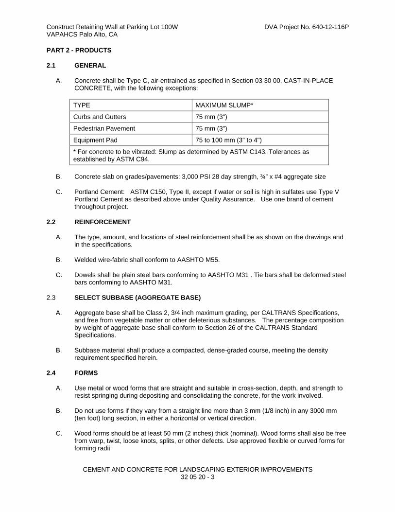
Construct Retaining Wall at Parking Lot 100W DVA Project No. 640-12-116P VAPAHCS Palo Alto, CA
CEMENT AND CONCRETE FOR LANDSCAPING EXTERIOR IMPROVEMENTS
32 05 20 - 3
PART 2 - PRODUCTS
2.1 GENERAL
A. Concrete shall be Type C, air-entrained as specified in Section 03 30 00, CAST-IN-PLACE CONCRETE, with the following exceptions:
TYPE MAXIMUM SLUMP*
Curbs and Gutters 75 mm (3")
Pedestrian Pavement 75 mm (3")
Equipment Pad 75 to 100 mm (3" to 4")
* For concrete to be vibrated: Slump as determined by ASTM C143. Tolerances as established by ASTM C94.
B. Concrete slab on grades/pavements: 3,000 PSI 28 day strength, ¾” x #4 aggregate size
C. Portland Cement: ASTM C150, Type II, except if water or soil is high in sulfates use Type V Portland Cement as described above under Quality Assurance. Use one brand of cement throughout project.
2.2 REINFORCEMENT
A. The type, amount, and locations of steel reinforcement shall be as shown on the drawings and in the specifications.
B. Welded wire-fabric shall conform to AASHTO M55.
C. Dowels shall be plain steel bars conforming to AASHTO M31 . Tie bars shall be deformed steel bars conforming to AASHTO M31.
2.3 SELECT SUBBASE (AGGREGATE BASE)
A. Aggregate base shall be Class 2, 3/4 inch maximum grading, per CALTRANS Specifications, and free from vegetable matter or other deleterious substances. The percentage composition by weight of aggregate base shall conform to Section 26 of the CALTRANS Standard Specifications.
B. Subbase material shall produce a compacted, dense-graded course, meeting the density requirement specified herein.
2.4 FORMS
A. Use metal or wood forms that are straight and suitable in cross-section, depth, and strength to resist springing during depositing and consolidating the concrete, for the work involved.
B. Do not use forms if they vary from a straight line more than 3 mm (1/8 inch) in any 3000 mm (ten foot) long section, in either a horizontal or vertical direction.
C. Wood forms should be at least 50 mm (2 inches) thick (nominal). Wood forms shall also be free from warp, twist, loose knots, splits, or other defects. Use approved flexible or curved forms for forming radii.

Construct Retaining Wall at Parking Lot 100W DVA Project No. 640-12-116P VAPAHCS Palo Alto, CA
CEMENT AND CONCRETE FOR LANDSCAPING EXTERIOR IMPROVEMENTS
32 05 20 - 4
2.5 COLOR ADDITIVES
A. Color Additives/Pigments: Insoluble minerals, light fast, at least 95 percent passing #325 sieve complying with ASTM C979: Match Davis Colors, Los Angeles, CA ;(800) 356-4848; Color(s) shall be as shown on Drawings.
B. Color additives containing carbon black are not acceptable.
2.6 CURING COMPOUNDS FOR COLORED CONCRETE
A. Curing Compound for Colored Concrete: Water-base acrylic type, free of permanent color, oil or wax, complying with ASTM C309: Match Davis Colors, Los Angeles, CA (800) 356-4848; or equal.
2.7 CONCRETE CURING MATERIALS
A. Concrete curing materials shall conform to one of the following:
1. Burlap conforming to AASHTO M182 having a weight of 233 grams (seven ounces) or more per square meter (yard) when dry.
2. Impervious Sheeting conforming to AASHTO M171.
3. Liquid Membrane Curing Compound conforming to AASHTO M148 (ASTM C309), Type 2 and shall be free of paraffin or petroleum.
2.8 EXPANSION JOINT FILLERS
A. Fiber Expansion Joint: A non-extruding resilient filler, saturated with high quality bituminous materials having preserving characteristics. Conform to ASTM-D1751-04.
PART 3 - EXECUTION
3.1 SUBGRADE PENETRATION
A. Prepare, construct, and finish the subgrade as specified in Section 31 20 00, EARTH MOVING.
B. Maintain the subgrade in a smooth, compacted condition, in conformance with the required section and established grade until the succeeding operation has been accomplished.
3.2 SELECT SUBBASE (WHERE REQUIRED)
A. Mixing: Proportion the select subbase by weight or by volume in quantities so that the final approved job-mixed formula gradation, liquid limit, and plasticity index requirements will be met after subbase course has been placed and compacted. Add water in approved quantities, measured by weight or volume, in such a manner to produce a uniform blend.
B. Placing:
1. Place the mixed material on the prepared subgrade in a uniform layer to the required contour and grades, and to a loose depth not to exceed 200 mm (8 inches), and that when compacted, will produce a layer of the designated thickness.
2. When the designated compacted thickness exceeds 150 mm (6 inches), place the material in layers of equal thickness. Remove unsatisfactory areas and replace with satisfactory mixture, or mix the material in the area.

Construct Retaining Wall at Parking Lot 100W DVA Project No. 640-12-116P VAPAHCS Palo Alto, CA
CEMENT AND CONCRETE FOR LANDSCAPING EXTERIOR IMPROVEMENTS
32 05 20 - 5
3. In no case will the addition of thin layers of material be added to the top layer in order to meet grade.
4. If the elevation of the top layer is 13 mm (1/2 inch) or more below the grade, excavate the top layer and replace with new material to a depth of at least 75 mm (3 inches) in compacted thickness.
C. Compaction:
1. Perform compaction with approved equipment (hand or mechanical) well suited to the material being compacted.
2. Moisten or aerate the material as necessary to provide the moisture content that will readily facilitate obtaining the specified compaction with the equipment used.
3. Compact each layer to at least 95 percent or 100 percent of maximum density as determined by AASHTO T180 or AASHTO T99 respectively.
D. Smoothness Test and Thickness Control: Test the completed subbase for grade and cross section with a straight edge.
1. The surface of each layer shall not show any deviations in excess of 10 mm (3/8 inch).
2. The completed thickness shall be within 13 mm (1/2 inch) of the thickness as shown.
E. Protection:
1. Maintain the finished subbase in a smooth and compacted condition until the concrete has been placed.
2. When Contractor's subsequent operations or adverse weather disturbs the approved compacted subbase, excavate, and reconstruct it with new material meeting the requirements herein specified, at no additional cost to the VA.
3.3 SETTING FORMS
A. Base Support:
1. Compact the base material under the forms true to grade so that, when set, they will be uniformly supported for their entire length at the grade as shown.
2. Correct imperfections or variations in the base material grade by cutting or filling and compacting.
B. Setting:
1. Set forms sufficiently in advance of the placing of the concrete to permit the performance and approval of all operations required with and adjacent to the form lines.
2. Set forms to true line and grade and use stakes, clamps, spreaders, and braces to hold them rigidly in place so that the forms and joints are free from play or movement in any direction.
3. Forms shall conform to line and grade with an allowable tolerance of 3 mm (1/8 inch) when checked with a straightedge and shall not deviate from true line by more than 6 mm (1/4 inch) at any point.
4. Do not remove forms until removal will not result in damaged concrete or at such time to facilitate finishing.
5. Clean and oil forms each time they are used.
Construct Retaining Wall at Parking Lot 100W DVA Project No. 640-12-116P VAPAHCS Palo Alto, CA
CEMENT AND CONCRETE FOR LANDSCAPING EXTERIOR IMPROVEMENTS
32 05 20 - 6
C. The Contractor’s Registered Professional Land Surveyor, shall establish and control the alignment and the grade elevations of the forms or concrete slipforming machine operations.
1. Make necessary corrections to forms immediately before placing concrete.
2. When any form has been disturbed or any subgrade or subbase has become unstable, reset and recheck the form before placing concrete.
3.4 EQUIPMENT
A. The Resident Engineer shall approve equipment and tools necessary for handling materials and performing all parts of the work prior to commencement of work.
B. Maintain equipment and tools in satisfactory working condition at all times.
3.5 PLACING REINFORCEMENT
A. Reinforcement shall be free from dirt, oil, rust, scale or other substances that prevent the bonding of the concrete to the reinforcement.
B. Before the concrete is placed, the Resident Engineer shall approve the reinforcement, which shall be accurately and securely fastened in place with suitable supports and ties. The type, amount, and position of the reinforcement shall be as shown.
3.6 PLACING CONCRETE - GENERAL
A. Obtain approval of the Resident Engineer before placing concrete.
B. Plain non-colored, exposed concrete shall contain lampblack, approximately 3/4 pound of lampblack per cubic yard, as accepted by Resident Engineer.
C. Remove debris and other foreign material from between the forms before placing concrete. Obtain approval of the Resident Engineer before placing concrete.
D. Before the concrete is placed, uniformly moisten the subgrade, base, or subbase appropriately, avoiding puddles of water.
E. Convey concrete from mixer to final place of deposit by a method which will prevent segregation or loss of ingredients. Deposit concrete so that it requires as little handling as possible.
F. While being placed, spade or vibrate and compact the concrete with suitable tools to prevent the formation of voids or honeycomb pockets. Vibrate concrete well against forms and along joints. Over-vibration or manipulation causing segregation will not be permitted. Place concrete continuously between joints without bulkheads.
G. Install a construction joint whenever the placing of concrete is suspended for more than 30 minutes and at the end of each day's work.
H. Workmen or construction equipment coated with foreign material shall not be permitted to walk or operate in the concrete during placement and finishing operations.

Construct Retaining Wall at Parking Lot 100W DVA Project No. 640-12-116P VAPAHCS Palo Alto, CA
CEMENT AND CONCRETE FOR LANDSCAPING EXTERIOR IMPROVEMENTS
32 05 20 - 7
3.7 PLACING CONCRETE FOR CURB AND GUTTER, PEDESTRIAN PAVEMENT AND EQUIPMENT PADS
A. Place concrete in the forms in one layer of such thickness that, when compacted and finished, it will conform to the cross section as shown.
B. Deposit concrete as near to joints as possible without disturbing them but do not dump onto a joint assembly.
C. After the concrete has been placed in the forms, use a strike-off guided by the side forms to bring the surface to the proper section to be compacted.
D. Consolidate the concrete thoroughly by tamping and spading, or with approved mechanical finishing equipment.
E. Finish the surface to grade with a wood or metal float.
F. All Concrete pads and pavements shall be constructed with sufficient slope to drain properly.
3.8 CONCRETE FINISHING - GENERAL
A. The sequence of operations, unless otherwise indicated, shall be as follows:
1. Consolidating, floating, straight-edging, troweling, texturing, and edging of joints.
2. Maintain finishing equipment and tools in a clean and approved condition.
3.9 CONCRETE FINISHING PEDESTRIAN PAVEMENT
A. Walks: Medium Sandblast Finish.Perform in as continuous an operation as possible, utilizing the same work crew to maintain continuity of finish.
Use and abrasive grit of the proper type and gradation to expose the aggregate and surrounding matrix surfaces to match the sample panel, as follows:
Medium Cut: approximately 1/8” to 3/16” depth
B. Finish the surfaces to grade and cross section with a metal float, trowled smooth and finished with a broom moistened with clear water.
C. Finish all slab edges, including those at formed joints, carefully with an edger having a radius as shown on the Drawings.
D. Unless otherwise indicated, edge the transverse joints before brooming. The brooming shall eliminate the flat surface left by the surface face of the edger. Execute the brooming so that the corrugation, thus produced, will be uniform in appearance and not more than 2 mm (1/16 inch) in depth and non-slip in conformance with ADA requirements.
E. The completed surface shall be uniform in color and free of surface blemishes, form marks, and tool marks. The finished surface of the pavement shall not vary more than 5 mm (3/16 inch) when tested with a 3000 mm (10 foot) straightedge.
F. The thickness of the pavement shall not vary more than 6 mm (1/4 inch).
Construct Retaining Wall at Parking Lot 100W DVA Project No. 640-12-116P VAPAHCS Palo Alto, CA
CEMENT AND CONCRETE FOR LANDSCAPING EXTERIOR IMPROVEMENTS
32 05 20 - 8
G. Remove and reconstruct irregularities exceeding the above for the full length between regularly scheduled joints.
3.10 CONCRETE FINISHING CURB AND GUTTER
A. Round the edges of the gutter and top of the curb with an edging tool to a radius of 6mm (1/4 inch) or as otherwise detailed.
B. Float the surfaces and finish with a smooth wood or metal float until true to grade and section and uniform in textures.
C. Finish the surfaces, while still wet, with a bristle type brush with longitudinal strokes.
D. Immediately after removing the front curb form, rub the face of the curb with a wood or concrete rubbing block and water until blemishes, form marks, and tool marks have been removed. Brush the surface, while still wet, in the same manner as the gutter and curb top.
E. Except at grade changes or curves, finished surfaces shall not vary more than 3 mm (1/8 inch) for gutter and 6 mm (1/4 inch) for top and face of curb, when tested with a 3000 mm (10 foot) straightedge.
F. Remove and reconstruct irregularities exceeding the above for the full length between regularly scheduled joints.
G. Correct any depressions which will not drain.
H. Visible surfaces and edges of finished curb and gutter shall be free of blemishes, form marks, and tool marks, and shall be uniform in color, shape, and appearance.
3.11 JOINTS - GENERAL
A. Place joints, where shown, conforming to the details as shown, and perpendicular to the finished grade of the concrete surface.
B. Joints shall be straight and continuous from edge to edge of the pavement.
3.12 CONTRACTION JOINTS
A. Unless otherwise indicated as sawcut on drawings, cut joints to depth as shown with a grooving tool or jointer of a radius as shown. Sawcut joints shall be sawn with a blade producing the required width and depth.
B. Plates shall remain in place until concrete has set sufficiently to hold its shape and shall then be removed.
C. Finish edges of all joints with an edging tool having the radius as shown, unless otherwise indicated as sawcut.
D. Score pedestrian pavement with a standard grooving tool or jointer.
3.13 EXPANSION JOINTS
A. Use a preformed expansion joint filler material of the thickness as shown to form expansion joints.
Construct Retaining Wall at Parking Lot 100W DVA Project No. 640-12-116P VAPAHCS Palo Alto, CA
CEMENT AND CONCRETE FOR LANDSCAPING EXTERIOR IMPROVEMENTS
32 05 20 - 9
B. Material shall extend the full depth of concrete, cut and shaped to the cross section as shown, except that top edges of joint filler shall be below the finished concrete surface where shown to allow for sealing.
C. Anchor with approved devices to prevent displacing during placing and finishing operations.
D. Round the edges of joints with an edging tool with 1/8" maximum radius.
E. Form expansion joints as follows:
1. Without dowels, about structures and features that project through, into, or against any site work concrete construction.
2. Using joint filler of the type, thickness, and width as shown.
3. Installed in such a manner as to form a complete, uniform separation between the structure and the site work concrete item.
3.14 CONSTRUCTION JOINTS
A. Locate longitudinal construction joints between slabs of vehicular pavement as shown.
B. Place transverse construction joints of the type shown, where indicated and whenever the placing of concrete is suspended for more than 30 minutes.
C. Use a butt-type joint with dowels in curb and gutter if the joint occurs at the location of a planned joint.
D. Use keyed joints with tiebars if the joint occurs in the middle third of the normal curb joint interval.
3.15 FORM REMOVAL
A. Forms shall remain in place at least 12 hours after the concrete has been placed. Remove forms without injuring the concrete.
B. Do not use bars or heavy tools against the concrete in removing the forms. Promptly repair any concrete found defective after form removal.
3.16 CURING OF CONCRETE
A. Cure concrete by one of the following methods appropriate to the weather conditions and local construction practices, against loss of moisture, and rapid temperature changes for at least seven days from the beginning of the curing operation. Protect unhardened concrete from rain and flowing water. All equipment needed for adequate curing and protection of the concrete shall be on hand and ready to install before actual concrete placement begins. Provide protection as necessary to prevent cracking of the pavement due to temperature changes during the curing period. If any selected method of curing does not afford the proper curing and protection against concrete cracking, remove and replace the damaged pavement and employ another method of curing as directed by the Resident Engineer.
B. Burlap Mat: Provide a minimum of two layers kept saturated with water for the curing period. Mats shall overlap each other at least 150 mm (6 inches).
C. Impervious Sheeting: Use waterproof paper, polyethylene-coated burlap, or polyethylene sheeting. Polyethylene shall be at lease 0.1 mm (4 mils) in thickness. Wet the entire exposed

Construct Retaining Wall at Parking Lot 100W DVA Project No. 640-12-116P VAPAHCS Palo Alto, CA
CEMENT AND CONCRETE FOR LANDSCAPING EXTERIOR IMPROVEMENTS
32 05 20 - 10
concrete surface with a fine spray of water and then cover with the sheeting material. Sheets shall overlap each other at least 300 mm (12 inches). Securely anchor sheeting.
D. Liquid Membrane Curing:
1. For colored concrete, refer to CURING COMPOUNDS FOR COLORED CONCRETE above in PART 2- PRODUCTS. Apply as recommended by manufacturer.
3.17 CLEANING
A. After completion of the curing period:
1. Remove the curing material (other than liquid membrane).
2. Sweep the concrete clean.
3. After removal of all foreign matter from the joints, seal joints as herein specified.
4. Clean the entire concrete of all debris and construction equipment as soon as curing and sealing of joints has been completed.
3.18 PROTECTION
A. The contractor shall protect the concrete against all damage prior to final acceptance by the Government. Remove concrete containing excessive cracking, fractures, spalling, or other defects and reconstruct the entire section between regularly scheduled joints, when directed by the Resident Engineer, and at no additional cost to the Government. Exclude traffic from vehicular pavement until the concrete is at least seven days old, or for a longer period of time if so directed by the Resident Engineer.
3.19 FINAL CLEAN-UP
A. Remove all debris, rubbish and excess material from the Station.
- - - E N D - - -
Construct Retaining Wall at Parking Lot 100W DVA Project No. 640-12-116P Palo Alto Division VA Palo Alto Health Care System
ASPHALT PAVING 32 12 16 - 1
SECTION 32 12 16
ASPHALT PAVING
PART 1 - GENERAL
1.1 DESCRIPTION
A. This work shall cover the composition, mixing, construction upon the prepared subgrade, and the protection of hot asphalt concrete pavement. The hot asphalt concrete pavement shall consist of an aggregate or asphalt base course and asphalt surface course constructed in conformity with the lines, grades, thickness, and cross sections as shown. Each course shall be constructed to the depth, section, or elevation required by the drawings and shall be rolled, finished, and approved before the placement of the next course.
1.2 RELATED WORK
A. Laboratory and field testing requirements: Section 01 45 29, TESTING LABORATORY SERVICES.
B. Subgrade Preparation: Paragraph 3.3 and Section 31 20 00, EARTH MOVING.
C. Pavement Markings: Section 32 17 23, PAVEMENT MARKINGS.
1.3 INSPECTION OF PLANT AND EQUIPMENT
A. Resident Engineer shall have access at all times to all parts of the material producing plants for checking the mixing operations and materials and the adequacy of the equipment in use.
1.4 ALIGNMENT AND GRADE CONTROL
A. Contractor’s Registered Professional Land Surveyor shall establish and control the pavement (aggregate or asphalt base course and asphalt surface course) alignments, grades, elevations, and cross sections as shown on the Drawings.
1.5 SUBMITTALS
A. In accordance with Section 01 33 23, SHOP DRAWINGS, PRODUCT DATA, AND SAMPLES, furnish the following:
B. Data and Test Reports:
1. Aggregate Base Course: Sources, gradation, liquid limit, plasticity index, percentage of wear, and other tests required by the Caltrans Standard Specifications.
2. Asphalt Base/Surface Course: Aggregate source, gradation, soundness loss, percentage of wear, and other tests required by the Caltrans Standard Specifications.
3. Job-mix formula.
C. Certifications:
1. Asphalt prime and tack coat material certificate of conformance to the Caltrans Standard Specifications.
2. Asphalt cement certificate of conformance to the Caltrans Standard Specifications.
Construct Retaining Wall at Parking Lot 100W DVA Project No. 640-12-116P Palo Alto Division VA Palo Alto Health Care System
ASPHALT PAVING 32 12 16 - 2
3. Job-mix certification - Submit plant mix certification that mix equals or exceeds the Caltrans Standard Specifications.
D. Provide MSDS (Material Safety Data Sheets) for all chemicals used on ground.
PART 2 - PRODUCTS
2.1 GENERAL
A. Aggregate base and asphalt concrete materials shall conform to the requirements of the following and other appropriate sections of the latest version of the Caltrans Standard Specifications, including amendments, addenda and errata. Where the term "Engineer" or "Commission" is referenced in the Caltrans Standard Specifications, it shall mean the VA Resident Engineer.
2.2 AGGREGATES
A. Provide aggregates consisting of crushed stone, gravel, sand, or other sound, durable mineral materials processed and blended, and naturally combined. Conform to Caltrans Standard Specifications, section 26-1.02, Class 2, 3/4" maximum aggregate size.
B. Aggregates for asphaltic concrete paving: in conformance with Caltrans Standard Specifications, section 39-1.02E. 3/4" HMA. Aggregates for asphaltic concrete paving: in conformance with Caltrans Standard Specifications, section 39-1.02E. 3/4" HMA.
2.3 ASPHALTS
A. In conformance with Caltrans Standard Specifications, Sections 92 and 94.
1. Asphalt binder: Grade PG 64-10 or PG 64-16.
2. Tack coat: Uniformly emulsified, grade SS-1H
2.4 SEALER
A. Provide a sealer consisting of suitable fibrated chemical type asphalt base binders and fillers having a container consistency suitable for troweling after thorough stirring, and containing no clay or other deleterious substance.
B. Where conflicts arise between this specification and the requirements in the latest version of the State Highway Specifications, the State Specifications shall control.
PART 3 - EXECUTION
3.1 GENERAL
A. Asphalt Concrete Paving equipment, weather limitations, job-mix formula, mixing, construction methods, compaction, finishing, tolerance, and protection shall conform to the requirements of the appropriate sections of the State Highway Specifications for the type of material specified.
3.2 MIXING ASPHALTIC CONCRETE MATERIALS
A. Provide hot plant-mixed asphaltic concrete paving materials.
1. Temperature leaving the plant: 143 degrees C(290 degrees F) minimum, 160 degrees C(320 degrees F) maximum.
Construct Retaining Wall at Parking Lot 100W DVA Project No. 640-12-116P Palo Alto Division VA Palo Alto Health Care System
ASPHALT PAVING 32 12 16 - 3
2. Temperature at time of placing: 138 degrees C(280 degrees F) minimum.
3.3 SUBGRADE
A. Shape to line and grade and compact with self-propelled rollers.
B. All depressions that develop under rolling shall be filled with acceptable material and the area re-rolled.
C. Soft areas shall be removed and filled with acceptable materials and the area re-rolled.
D. Should the subgrade become rutted or displaced prior to the placing of the subbase, it shall be reworked to bring to line and grade.
E. Proof-roll the subgrade with maximum 45 tonne (50 ton) gross weight dump truck as directed by VA Resident Engineer or VA Contracting Officer under the review of the Geotechnical Engineer. If pumping, pushing, or other movement is observed, rework the area to provide a stable and compacted subgrade.
3.4 BASE COURSES
A. Base
1. Spread and compact to the thickness shown on the drawings.
2. Rolling shall begin at the sides and continue toward the center and shall continue until there is no movement ahead of the roller.
3. After completion of the base rolling there shall be no hauling over the base other than the delivery of material for the top course.
B. Thickness tolerance: Provide the compacted thicknesses shown on the Drawings within a tolerance of minus 0.0mm (0.0") to plus 12.7mm (0.5").
C. Smoothness tolerance: Provide the lines and grades shown on the Drawings within a tolerance of 5mm in 3m (3/16 inch in ten feet).
D. Moisture content: Use only the amount of moisture needed to achieve the specified compaction.
3.5 PLACEMENT OF ASPHALTIC CONCRETE PAVING
A. Remove all loose materials from the compacted base.
B. Apply the specified tack coat where required, and allow to dry in accordance with the manufacturer’s recommendations as approved by the Architect or Engineer.
C. Receipt of asphaltic concrete materials:
1. Do not accept material unless it is covered with a tarpaulin until unloaded, and unless the material has a temperature of not less than 130 degrees C(280 degrees F).
2. Do not commence placement of asphaltic concrete materials when the atmospheric temperature is below 10 degrees C (50 degrees F), not during fog, rain, or other unsuitable conditions.
D. Spreading:
Construct Retaining Wall at Parking Lot 100W DVA Project No. 640-12-116P Palo Alto Division VA Palo Alto Health Care System
ASPHALT PAVING 32 12 16 - 4
1. Spread material in a manner that requires the least handling.
2. Where thickness of finished paving will be 76mm (3") or less, spread in one layer.
E. Rolling:
1. After the material has been spread to the proper depth, roll until the surface is hard, smooth, unyielding, and true to the thickness and elevations shown own the drawings.
2. Roll in at least two directions until no roller marks are visible.
3. Finished paving smoothness tolerance:
a. No depressions which will retain standing water.
b. No deviation greater than 3mm in 1.8m (1/8" in six feet).
3.6 APPLICATION OF SEAL COAT
A. Prepare the surfaces, mix the seal coat material, and apply in accordance with the manufacturer’s recommendations as approved by the Architect or Engineer.
B. Apply one coat of the specified sealer.
C. Achieve a finished surface seal which, when dry and thoroughly set, is smooth, tough, resilient, of uniform black color, and free from coarse textured areas, lap marks, ridges, and other surface irregularities.
3.7 PROTECTION
A. Protect the asphaltic concrete paved areas from traffic until the sealer is set and cured and does not pick up under foot or wheeled traffic.
3.8 FINAL CLEAN-UP
A. Remove all debris, rubbish, and excess material from the work area.
--- E N D---
Construct Retaining Wall at Parking Lot 100W DVA Project No. 640-12-116P Palo Alto Division VA Palo Alto Health Care System
PAVEMENT MARKINGS 32 17 23 - 1
SECTION 32 17 23 PAVEMENT MARKINGS
PART 1 - GENERAL
1.1 DESCRIPTION
A. This work shall consist of furnishing and applying paint and reflective glass beads on pavement surfaces, in the form of traffic lanes, parking bays, areas restricted to handicapped persons, crosswalks, and other detail pavement markings, in accordance with the details as shown or as prescribed by the Resident Engineer. Conform to the Manual on Uniform Traffic Control Devices for Streets and Highways, published by the U.S. Department of Transportation, Federal Highway Administration, for details not shown.
1.2 SUBMITTALS
A. In accordance with Section 01 33 23, SHOP DRAWINGS, PRODUCT DATA, AND SAMPLES, furnish Manufacturer's Certificates and Data certifying that the following materials conform to the requirements specified.
B. Paint.
C. Reflective Glass Beads
1.3 APPLICABLE PUBLICATIONS
A. The publications listed below form a part of this specification to the extent referenced. The publications are referenced in the text by the basic designation only.
B. Federal Specifications (Fed. Spec.):
1. TT-B-1325C Beads (Glass Spheres); Retro-Reflective
2. TT-P-1952D Paint, Traffic Black, and Airfield Marking, Waterborne
C. Master Painters Institute (MPI):
1. Approved Product List - 2010
D. Caltrans: State Standard Specifications, Section 84, Traffic Stripes and Pavement Markings
PART 2 - PRODUCTS
2.1 PAINT
A. Paint for marking pavement (parking lot and zone marking) shall conform to MPI No. 97, color as shown. Paint for obliterating existing markings shall conform to Fed. Spec. TT-P-1952D. Paint shall be in containers of at least 18 L (5 gallons). A certificate shall accompany each batch of paint stating compliance with the applicable publication.
2.2 REFLECTIVE GLASS BEADS
A. Beads shall conform to Fed. Spec. TT-B-1325C, Type I, Gradation A. When used in regions of high humidity, coat beads with silicone or other suitable waterproofing material to assure free flow. Furnish the glass beads in containers suitable for handling and strong enough to prevent

Construct Retaining Wall at Parking Lot 100W DVA Project No. 640-12-116P Palo Alto Division VA Palo Alto Health Care System
PAVEMENT MARKINGS 32 17 23 - 2
loss during shipment. A certificate shall accompany each batch of beads stating compliance with this section.
2.3 PAINT APPLICATOR
A. Apply all marking by approved mechanical equipment. The equipment shall provide constant agitation of paint and travel at controlled speeds. Synchronize one or more paint "guns" to automatically begin and cut off paint flow in the case of skip lines. The equipment shall have manual control to apply continuous lines of varying length and marking widths as shown. Provide pneumatic spray guns for hand application of paint in areas where a mobile paint applicator cannot be used. If the equipment does not have a glass bead dispenser, use a separate piece of equipment. Adjust and synchronize the equipment with the paint applicator so that the reflective beads are distributed uniformly on the paint lines within ten seconds without any waste. An experienced technician that is thoroughly familiar with equipment, materials, and marking layouts shall control all painting equipment and operations.
2.4 SANDBLASTING EQUIPMENT
A. Sandblasting equipment shall include an air compressor, hoses, and nozzles of proper size and capacity as required for cleaning surfaces to be painted. The compressor shall furnish not less than 0.08 m3/s (150 cfm) of air at a pressure of not less than 625 kPa (90 psi) at each nozzle used.
PART 3 - EXECUTION
3.1 SURFACE PREPARATION
A. Allow new pavement surfaces to cure for a period of not less than 14 days before application of marking materials.
B. Thoroughly clean all surfaces to be marked before application of paint. Remove dust, dirt, and other granular surface deposits by sweeping, blowing with compressed air, rinsing with water, or a combination of these methods. Completely remove rubber deposits, existing paint markings, and other coatings adhering to the pavement with scrapers, wire brushings, sandblasting, mechanical abrasion, or approved chemicals as directed by the Resident Engineer. The application of paint conforming to Fed. Spec. TT-P-1952D is an option to removal of existing paint markings on asphalt pavement. Apply the black paint in as many coats as necessary to completely obliterate the existing markings. Where oil or grease are present on old pavements to be marked, scrub affected areas with several applications of trisodium phosphate solution or other approved detergent or degreaser, and rinse thoroughly after each application. After cleaning, seal oil-soaked areas with cut shellac to prevent bleeding through the new paint. Pavement marking shall follow as closely as practicable after the surface has been cleaned and dried, but do not begin any marking until the Resident Engineer has inspected the surface and gives permission to proceed. The Contractor shall establish control points for marking and provide templates to control paint application by type and color at necessary intervals. The Contractor is responsible to preserve and apply marking in conformance with the established control points.
3.2 APPLICATION
A. Apply uniformly painted and reflective pavement marking of required color(s), length, and width with true, sharp edges and ends on properly cured, prepared, and dried surfaces in conformance with the details as shown and established control points. The length and width of lines shall conform within a tolerance of plus or minus 75 mm (3 inches) and plus or minus 3 mm (1/8 inch),
Construct Retaining Wall at Parking Lot 100W DVA Project No. 640-12-116P Palo Alto Division VA Palo Alto Health Care System
PAVEMENT MARKINGS 32 17 23 - 3
respectively, in the case of skip markings. The length of intervals shall not exceed the line length tolerance. Temperature of the surface to be painted and the atmosphere shall be above 10°C�(50°F� and less than 35°C�(95°F�. Apply the paint at a wet film thickness of 0.4 mm (0.015 inch). Disperse reflective glass beads evenly on the wet paint at a rate of 720 g/L (6 pounds per gallon) of paint. Apply paint in one coat. At the direction of the Resident Engineer, markings showing light spots may receive additional coats. The maximum drying time requirements of the paint specifications will be strictly enforced, to prevent undue softening of asphalt, and pick-up, displacement, or discoloration by tires of traffic. If there is a deficiency in drying of the marking, discontinue paint operations until cause of the slow drying is determined and corrected. Remove and replace marking that is applied at less than minimum material rates; deviates from true alignment; exceeds stipulated length and width tolerances; or shows light spots, faulty distribution of beads, smears, or other deficiencies or irregularities. Use carefully controlled sand blasting, approved grinding equipment, or other approved method to remove marking so that the surface to which the marking was applied will not be damaged.
3.3 PROTECTION
A. Conduct operations in such a manner that necessary traffic can move without hindrance. Protect the newly painted markings so that, insofar as possible, the tires of passing vehicles will not pick up paint. Place warning signs at the beginning of the wet line, and at points well in advance of the marking equipment for alerting approaching traffic from both directions. Place small flags or other similarly effective small objects near freshly applied markings at frequent intervals to reduce crossing by traffic. Efface and replace damaged portions of markings at no additional cost to the Government.
3.4 DETAIL PAVEMENT MARKING
A. Use Detail Pavement Markings, exclusive of actual traffic lane marking, at exit and entrance islands and turnouts, on curbs, at crosswalks, at parking bays, and at such other locations as shown. Show the International Handicapped Symbol at indicated parking spaces. Color shall be as shown. Apply paint for the symbol using a suitable template that will provide a pavement marking with true, sharp edges and ends. Place detail pavement markings of the color(s), width(s) and length(s), and design pattern at the locations shown.
3.5 TEMPORARY PAVEMENT MARKING
A. When shown or directed by the Resident Engineer, apply Temporary Pavement Markings of the color(s), width(s) and length(s) shown or directed. After the temporary marking has served its purpose and when so ordered by the Resident Engineer, remove temporary marking by carefully controlled sandblasting, approved grinding equipment, or other approved method so that the surface to which the marking was applied will not be damaged. As an option, an approved preformed pressure sensitive, reflective, adhesive tape type of temporary pavement marking of the required color(s), width(s) and length(s) may be furnished and used in lieu of temporary painted and reflective marking. The Contractor shall be fully responsible for the continued durability and effectiveness of such marking during the period for which its use is required. Remove any unsatisfactory tape type marking and replace with painted and reflective markings at no additional cost to the Government.
3.6 FINAL CLEAN-UP
A. Remove all debris, rubbish and excess material from the Station.
--- E N D---

Construct Retaining Wall at Parking Lot 100W DVA Project No. 640-12-116P VAPAHCS Palo Alto, CA
PLANTING IRRIGATION
32 84 00 - 1
SECTION 32 84 00
PLANTING IRRIGATION
PART 1 - GENERAL
1.1 DESCRIPTION
A. An automatically-controlled irrigation system, complete, including controller, piping, , drip emitters, sprinkler heads, valves, controls, control wiring, fittings, electrical connections and necessary accessories.
1.2 RELATED WORK
A. Concrete: Section 32 05 20, CEMENT AND CONCRETE FOR LANDSCAPE EXTERIOR IMPROVEMENTS
B. Planting: Section 32 90 00, PLANTING
C. Maintenance of Existing Utilities: Section 01 00 00, GENERAL REQUIREMENTS.
D. Excavation, Trench Widths, Pipe Bedding, Backfill, Shoring, Sheeting, Bracing: Section 31 20 00, EARTH MOVING.
E. Division 26, ELECTRICAL.
1.3 QUALITY ASSURANCE
A. Criteria:
1. Manufacturer regularly and presently manufactures the item submitted as one of their principal products.
2. There is a permanent service organization, maintained or trained by the manufacturer, which will render satisfactory service within eight hours of receipt of notification that service is requested.
3. Installer, or supplier of a service, has technical qualifications, experience, and trained personnel and facilities to perform the specified work.
B. Products Criteria:
1. Multiple Units: When two or more units of the same type or class of materials or equipment are required, these units are products of one manufacturer.
2. Assembled Units: Manufacturers of equipment assemblies, which use components made by others, assume complete responsibility for the final assembled product.
a. All components of an assembled unit need not be products of the same manufacturer but component parts which are alike are the product of a single manufacturer.
b. Components are compatible with each other and with the total assembly for the intended service.
3. Nameplates: Nameplate bearing manufacturer's name or identification trademark securely affixed in a conspicuous place on equipment, or name or trademark cast
Construct Retaining Wall at Parking Lot 100W DVA Project No. 640-12-116P VAPAHCS Palo Alto, CA
PLANTING IRRIGATION
32 84 00 - 2
integrally with equipment, stamped, or otherwise permanently marked on each item of equipment.
C. System Requirements:
1. Full and complete coverage is required. Contractor shall, at no additional cost to the Government, make necessary adjustments to layout required to achieve full coverage of irrigated areas without overthrow on roadways, sidewalks, window wells, or buildings and to protect trees from close high spray velocity.
2. Layout work as closely as possible to drawings. Drawings are diagrammatic to the extent that swing joints, offsets and all fittings are not shown. Lines are to be common trenched wherever possible.
3. Locations of remote control valves is schematic. Remote control valves shall be grouped wherever possible and aligned at a set dimension back of curb along roads.
4. Irrigation lines and control wire shall run through designated utility lanes or beside roadways where most appropriate.
5. Connect new pipe systems to existing mains where shown and specified. Disconnect and abandon existing irrigation system to be abandoned.
6. Connect existing and new RCV wires to new controllers where shown and as specified as accepted by Resident Engineer.
D. Maintenance and Operating Instructions: Prior to final acceptance, verbal instructions, for a period of not less than 8 hours, shall be provided to the operating personnel. Provide two additional years of software support for one hour each month. Provide manuals as specified in Section 01 00 00, GENERAL REQUIREMENTS.
E. Completely program controller and satellites according to approved irrigation schedule.
F. Follow manufacturer's instructions for installation.
G. Manufacturer of Control Systems to certify Control System is complete, including all related components, and totally operational. Submit certificate to Resident Engineer.
H. As-Built Record Drawings: Maintain a complete set of as-built drawings which shall be corrected daily to show changes in locations of all pipe, valves, pumps and related irrigation equipment. Valves shall be shown with dimensions to reference points.
I. Controller Chart:
1. Prepare a map diagram showing location of all valves, lateral lines, and route of the control wires. Identify all valves as to size, station, number and type of irrigation. "As-built" drawings must be approved before charts are prepared.
2. Provide one controller chart showing the area covered by controller for each automatic controller supplied at the maximum size controller door will allow. Chart shall be a reduced drawing of the actual "as-built" system. If controller sequence is not legible when the drawing is reduced to door size, the drawing shall be enlarged to a size that is readable and placed folded, in a sealed plastic container, inside the controller door.
3. Chart shall be a blackline print with a different color used to show area of coverage for each station. Charts must be completed and approved prior to final inspection of the irrigation system.
Construct Retaining Wall at Parking Lot 100W DVA Project No. 640-12-116P VAPAHCS Palo Alto, CA
PLANTING IRRIGATION
32 84 00 - 3
1.4 SUBMITTALS
A. Submit as one package in accordance with Section 01 33 23, SHOP DRAWINGS, PRODUCT DATA, AND SAMPLES.
B. Manufacturers' Literature and Data:
1. Piping.
2. Jointing materials.
3. Valves.
4. Frames and covers.
5. Strainers.
6. Pressure gages.
7. Automatic control equipment.
8. Sprinkler heads.
9. Quick couplers.
10. Valve boxes.
C. Complete detailed layout shop drawings covering design of system showing pipe sizes and lengths; fittings, locations, types and sizes of sprinkler heads; controls; valves; location and mounting details of electrical control equipment; complete wiring diagram showing routes and wire sizes; wiring details and source of current and connections to existing services. Do not start work before final shop drawing approval.
D. Name and address of a permanent service organization maintained or trained by the manufacturers that will render satisfactory service within eight hours of receipt of notification that service is requested.
E. Reproducible "as-built" drawings.
F. After "as-built" drawings have been approved, submit print of controller chart.
1.5 APPLICABLE PUBLICATIONS
A. The publications listed below form a part of this specification to the extent referenced. The publications are referenced in the text by the basic designation only.
B. Federal Specifications (Fed. Spec.):
1. A-A-60005 Frames, Covers, Gratings, Steps, Sump And Catch Basin, Manhole
C. American National Standard Institute (ANSI):
1. B40.100-05 Gauges-Pressure Indicating Dial Type-Elastic Element
D. American Society of Sanitary Engineers (ASSE):
1. 1013-2009 Reduced Pressure Principle Backflow Preventers
E. American Society for Testing and Materials (ASTM):
1. B61-08 Steam or Valve Bronze Castings
Construct Retaining Wall at Parking Lot 100W DVA Project No. 640-12-116P VAPAHCS Palo Alto, CA
PLANTING IRRIGATION
32 84 00 - 4
2. B62-09 Composition Bronze or Ounce Metal Castings
3. D1785-06 Poly(Vinyl Chloride) (PVC) Plastic Pipe, Schedule 40, 80, and 120
4. D2241-05 Poly(Vinyl Chloride) (PVC) Pressure-Rated Pipe (SDR Series)
5. D2464-06 Threaded Poly (Vinyl Chloride) (PVC) Plastic Pipe Fittings, Schedule 80
6. D2466-06 Poly(Vinyl Chloride) (PVC) Plastic Pipe Fittings, Schedule 40
7. D2564-04 Solvent Cements for Poly (Vinyl Chloride) (PVC) Plastic Piping Systems
8. D2855-96(R2002) Making Solvent Cemented Joints with Poly(Vinyl Chloride) (PVC) Pipe and Fittings
9. F477-08 Elastomeric Seals (Gaskets) for Joining Plastic Pipe
F. American Water Works Association (AWWA):
1. C110/A21.10-08 Ductile-Iron and Gray-Iron Fittings, 3-Inch Through 48-Inch for Water
2. C111/A21.11-06 Rubber-Gasket Joints for Ductile-Iron Pressure Pipe and Fittings.
3. C115/A21.15-05 Flanged Ductile-Iron Pipe with Ductile-Iron or Gray-Iron Threaded Flanges
4. C151/A21.51-09 Ductile-Iron Pipe, Centrifugally Cast, for Water C153/A21.53-00
5. C504-06 Rubber Seated Butterfly Valves
6. C600-05 Installation of Ductile-Iron Water Mains and Their Appurtenances
7. C900-07 Polyvinyl Chloride (PVC) Pressure Pipe and Fabricated Fittings 4in. Through 12in.
G. Manufacturers Standardization Society (MSS):
1. SP-70-06 Gray Iron Gate Valves, Flanged and Thread Ends
H. References, Codes and Standards: 1. AB 325 and 1881 State of California Model Water Efficient Landscape Ordinance,
California Code of Regulations Title 23. 2. California Environmental Quality Act (CEQA) 3. Water Use Classification of Landscape Species (WUCOLS). 4. American Society of Irrigation Consultants (ASIC) Design Guidelines. 5. California Landscape Standards, California Landscape Contractors Association, (CLCA)
Sacramento, California. 6. CAL-OSHA, title 8, Subchapter 4-Construction Safety Orders and Subchapter 7-General
Industry Safety Orders. 7. California Electric Code. 8. California Plumbing Code (UPC) published by the Association of Western Plumbing
Officials. 9. NFPA 24, Section 10.4, Depth of Cover. 10. Underwriters Laboratories (UL): Electrical wiring, controls, motors and devices, UL listed
and so labeled. 11. American Society of Testing Materials (ASTM)
Construct Retaining Wall at Parking Lot 100W DVA Project No. 640-12-116P VAPAHCS Palo Alto, CA
PLANTING IRRIGATION
32 84 00 - 5
PART 2 - PRODUCTS
2.1 PIPING
A. Irrigation Mains: Polyvinyl Chloride, Schedule 40, solvent welded.
Irrigation Laterals: Polyvinyl Chloride, Schedule 40, solvent welded.
B. Threaded Pipe: Polyvinyl Chloride, ASTM D1785, PVC 1120, Schedule 80, for threaded connections, risers and swing joints.
C. Above Grade and in Concrete Pit: AWWA C115, flanged joints and fittings working pressure 1025 kPa (150 psi).
D. Fittings:
1. Irrigation Mains (Ductile Iron and PVC Pipe): Ductile Iron, AWWA C110.
2. Irrigation Laterals: PVC, schedule 40, solvent welded socket type, ASTM D2466.
3. Threaded Pipe: PVC, schedule 80, ASTM D2464.
4. Swing Joints: Threaded fittings with elastomeric seals that allow 360 degree rotation, and designed for minimum 1375 kPa (200 psig) working pressure.
E. Jointing Materials:
1. Irrigation Laterals: Solvent cement, ASTM D2564.
2.2 VALVES (EXCEPT REMOTE CONTROL VALVES)
A. Underground Shut-Off Valves: Provide One of the Following:
1. Gate valves 50 mm (2 inches) and larger: Iron body, bronze mounted, double disc with parallel or inclined seats, non-rising stem turning clockwise to close, 1025 kPa (150 psi) minimum working pressure. AWWA C504.
2. Butterfly valves 80 mm (3 inches) and larger: cast iron body with stainless steel shaft, ductile iron valve disc and resilient rubber coated, 1025 kPa (150 psi) minimum pressure. AWWA C504.
3. Ball valves (for isolation valves 1-1/2" and smaller): Full-port ball valves with bronze body, PTFE seats, and 90 degree on/off handle. Ball valves to have NPT female end connections.
B. Operations:
1. Underground: furnish valves with 50 mm (2 inch) nut for T-Handle socket wrench operation.
2. Above ground and in pits: MSS SP-70, with handwheels.
3. All butterfly valves 150 mm (6 inches) and above shall have enclosed gear drive operators.
4. Ends of valves shall accommodate the type of pipe installed.
C. Check: Swing.
1. Smaller than 100 mm (4 inches): Bronze body and bonnet, ASTM B61 or B62, 850 kPa (125 pound) WSP.
Construct Retaining Wall at Parking Lot 100W DVA Project No. 640-12-116P VAPAHCS Palo Alto, CA
PLANTING IRRIGATION
32 84 00 - 6
2. One hundred mm (4 inches) and larger: Iron body, bronze trim, vertical or horizontal installation, flange connection, 1375 kPa (200 pound) WOG.
D. Pressure Reducing Valve: Cast steel body with renewable seats, with stainless steel trim. Flow passages and all parts designed to withstand high velocity applications, flange connected.
2.3 VALVE BOX
A. Gate and Butterfly Valve: Valve boxes shall be precast concrete (from Rigid Cast Iron Forms) with compressive strength of the concrete in excess of 30 Mpa (4000 psi). Box shall be of such length to be adapted to depth of cover required over pipe at valve location. Mark box cover to differentiate between lawn irrigation system and domestic water supply system and set flush with finished grade. Provide 2 "T" handle socket wrenches of 15 mm (5/8 inch) round stock with sufficient length to extend 600 mm (2 feet) above top of deepest valve box cover.
B. Remote Control Valves: When in pavement, valve boxes shall be precast concrete (from Rigid Cast Iron Forms) with compressive strength of the concrete in excess of 30 MPa (4000 psi). In planter areas, valve boxes shall be HDPE structural foam Type A, Class III, black in color. Box shall be minimum 475 mm (19 inches) long by 350 mm (14 inches) deep with key-lockable hinged cast iron cover.
1. After installation, label boxes with two 80 mm (3 inch) size stencils designated controller and circuit numbers with permanent white epoxy paint. Numbers shall be placed at center of valve cover and shall face nearest main road or service road.
2. Furnish 2 750 mm (30 inch) long valve adjustment keys.
2.4 STRAINERS
A. Basket or "Y" type with brass strainer basket. Body smaller than 70 mm (2-1/2 inch) shall be brass or bronze; 70 mm (2-1/2 inch) and larger shall be cast iron or semi-steel. Strainer cover to be furnished with blow-off connection and shut-off valve to accommodate 20 mm (3/4 inch) diameter hose connection.
2.5 PRESSURE GAUGES:
A. ANSI B40 .100, 114 mm (4-1/2 inch) diameter, all metal case, bottom connected. Dial shall be either dead black or white lacquered throughout. Provide shut-off cocks. Maximum graduations of 10 kPa (2 psi).
2.6 Flow Meter
A. Housing to be a Sch 80 polyvinyl chloride tee or bronze tee.
B. Have a pulsing output which operates at 9VDC and a pulse rate which is proportional to the GPM.
C. Fully compatible with the internal interface at each field controller.
D. Powered by the controller.
E. Replaceable metering insert.

Construct Retaining Wall at Parking Lot 100W DVA Project No. 640-12-116P VAPAHCS Palo Alto, CA
PLANTING IRRIGATION
32 84 00 - 7
F. Output wire shall be underground 14 AWG feeder wire.
G. Flow meter data can be accurately read by the controller up to 2,000 feet.
H. By the same manufacturer as the irrigation controller.
I. Shall feature a six-bladed design with a proprietary, non-magnetic sensing mechanism.
2.7 Moisture Sensors:
A. Solid-state tensiometer type.
B. Include data transmission circuitry which sends moisture level readings back to the irrigation controller using valve field wires.
C. Entire unit encased in epoxy.
D. Require no calibration for the life of the sensor.
E. Unaffected by temperature, salinity or changes in pH.
F. Accurately transmit moisture levels up to 3000 ft. across 14 AWG wire.
2.8 ET Measurement Device:
A. Powered by the field controller.
B. Measures ET directly in 0.01" increments and sends pulses directly to field controller.
C. Fully compatible with the internal interface at the field controller.
D. Mounted inside a stainless steel, vandal-resistant enclosure specifically designed for the device.
2.9 Rain Measurement Device:
A. Accurately measures rainfall in 0.01" increments by means of a tipping and emptying device mounted below the center of the collection dish.
B. Fully compatible with the internal interface at the field controller.
C. Operate between 32 deg F�and 125 deg F
D. Be constructed of anodized aluminum.
E. The controller shall provide the following programming parameters for rain.
1. Stop Irrigation after x.xx inches.
2. Maximum Rain in One Hour is x.xx inches.
3. Maximum Rain in 24 Hours is x.xx inches.
4. Let Rain only build up to x.xx inches.
Construct Retaining Wall at Parking Lot 100W DVA Project No. 640-12-116P VAPAHCS Palo Alto, CA
PLANTING IRRIGATION
32 84 00 - 8
2.10 AUTOMATIC CONTROL EQUIPMENT—INDEPENDENT ELECTRIC CONTROLLERS
A. Product as manufactured by Hydropoint (WeatherTRAK ET Pro2S Central) and conforming to this specification is acceptable.
B. Overall Control Concept. The electric automatic control system shall consist of one or more independent controllers which operate individual remote control valves in accordance with timing schedules programmed into the independent units. The number of units and location of the installations are shown on the drawings. The system shall have two-way, central Internet management with remote programming; monitoring and real-time notification of field alerts anywhere Internet access can be obtained. Whether data shall be collected from over 40,000 government regulated and privately owned weather stations across the US to combine with local wind, temperature, solar radiation and humidity variables to model a virtual on-site weather station.
C. The Control System consists of an Independent controller, Flow Meter, master valve and all accessories necessary to operate the irrigation system. All of these components and software shall be a standard package
D. Independent controller shall have the following characteristics:
1. Each controller shall be programmed automatically, daily over the Internet, based upon an ET micro zone representing approximately one square kilometer that is associated with the controllers exact longitude and latitude coordinates.
2. Station base watering time shall be developed by user selection of various sprinkler, soil, slope, and plant factors. Controller will develop watering station from the input factors. The controller will automatically decide whether to irrigate or not based upon the current day’s ET and the depletion of each station independent of one another
3. The stations shall allow for a rapid programming of a block of stations with the same watering time.
4. The controller shall have four programs with seven independent water day patterns and schedules. Each program has to start times with up to 20 cycles, with one water window per program. A second start time shall be available for high ET requirements in “auto mode" only.
5. The controller shall have independent station watering and watering day adjustment from -50% to +25% in 5% increments. Able to communicate with normally closed wired or wireless rain and rain/freeze switches, flow sensors and normally open or normally closed master valves.
6. Continuous flow monitoring and alert notification at the individual station and mainline levels. Preview mode that displays flow data and irrigation schedules for each station.
7. Report menu providing accumulated totals of flow usage and station runtime on a daily, weekly and monthly basis. Valve wire diagnostic circuit that identifies field wiring issues such as valve shorts or valve no-connects.
8. The ability to extend watering to following days when water window maximum has been reached. Coordinate a minimum of two flow monitors and master valves.
9. The controller shall be UL and C-UL approved.
10. Daily up dated ET irrigation schedules with an eight week go forward schedule for observing schedules for low-water use or other deep-rooted plant materials The controller shall have direct compatibility with hand-held remotes by simply connecting to a 32 pin connector.
Construct Retaining Wall at Parking Lot 100W DVA Project No. 640-12-116P VAPAHCS Palo Alto, CA
PLANTING IRRIGATION
32 84 00 - 9
11. The controller shall monitor the flow rate and be furnished with the following features: main line break flow detection, unscheduled flow detection, station upper limit flow detection, programmable flow check delay from one (1) to six (6) minutes, monitor and display measured flow in GPM, automatic flow learn mode for setting individual station limits or manual entry or semi-automatic monitor/set mode, global percentage adjust to automatically factor upper flow limits for stations, automatic station advancement for station overflow, audible and visual alert for all flow violations, intelligent upper-limit processing for concurrent station operation, automatic closure of normally open master valve on main line breaks or unscheduled overflow.
12. The controller shall be furnished with a feature for tracking water consumption in gallons to pinpoint specific water savings and conservation efforts. The controller shall be furnished with the following:
a. Programmable master valve either normally open or normally closed.
b. Programmable pump.
c. Programmable stacking or no stacking.
d. Programmable timer delay.
e. Programmable security code.
f. Programmable alarm to either enable or disable an audible alarm in the event of a flow violation.
g. Programmable flow check delay to set up a delay after any station changes, from one (1) minute to six (6) minutes, during which time no flow limits are checked.
h. View and clear accumulated gallons.
2.11 CONTROLLER ENCLOSURE PAD
A. The controller enclosure mounting pad assembly shall consist of a reinforced plastic support base, a 3/16 inch thick 5052 H 32 Marine grade aluminum mounting pad and stainless steel fastening breackets.
2.12 REMOTE CONTROL VALVES:
A. Each sprinkler section shall be automatically operated by a remote control valve installed underground and operated by a 24-volt AC electric solenoid Valves shall be of heavy duty construction and shall have manual shut-off and flow control adjustment and provide for manual operation. Install valves with union on one side to allow for easy removal. Valves shall have a minimum of 1025 kPa (150 psi) working pressure.
B. Valve body shall be cast-iron with brass bonnet, trim and renewable seat and have two inlet tappings (furnished with one plugged) to allow installation as either a straight or angle pattern valve.
C. Valves shall be diaphragm type designed to operate in water containing sand and debris, without the use of scrubbers or filters. To ensure this, the flush rod shall be tapered to vary the size of the port opening as the diaphragm raises and lowers, thus allowing trapped material to escape. Rod to be finished with a serrated surface to help scrub trapped material out. A The effective diaphragm working area/valve seating opening ratio must be a minimum of 3 to 1. Valves shall be completely serviceable from the top without removing valve body from the system. Furnish 2 750 mm (30 inch) long adjustment keys. Valves to operate at no more than 50 kPa (7 psi) pressure loss at manufacturers maximum recommended flow rate.
Construct Retaining Wall at Parking Lot 100W DVA Project No. 640-12-116P VAPAHCS Palo Alto, CA
PLANTING IRRIGATION
32 84 00 - 10
2.13 SPRINKLER HEADS
A. Shall be of make, type and performance as indicated on drawings. The entire internal assembly including filter screen, to be capable of removal from the top without removing the sprinkler case from the riser.
B. Rotator Pop-up Sprinklers:
C. Rotator to have multi-trajectory rotating stream delivery system. Body shall be pressure compensating at 40 psi and constructed of corrosion and UV resistant heavy-duty ABS. Body to have factory installed drain check valve capable of checking up to 14 feet in elevation change. Nozzles are shall have fully adjustable arcs and radius reduction up to 25%. Nozzle distances shall reign from 8 to 30 feet with corner, side strips and corner side strips. Precipitation rate to be low below 0.5 in./hr. at head-to-head coverage.
D. Shrub Spray Heads: Bodies to have an internal flow regulation in the pop-up stems at 30 PSI. The pop-up stem to have a shutoff device restricting water loss by 99% if the nozzle is removed or damaged. The body shall include a check valve to prevent low head drainage up to 10 feet in elevation change. The nozzles shall have a precipitation rate of 1 in./hr. or less. The nozzles to include a wide variety of arcs including 60°, 120°, 150°, 210°, 240°, side strip, left and right corner strips. The nozzles shall be match precipitation rate within each size and with other sizes. The nozzles shall be capable of achieving a minimum of 70% DU at standard head-to-head spacing. The sprinkler body, stem, nozzle and screen shall be constructed of heavy-duty, ultraviolet resistant plastic. It shall have a heavy duty stainless steel retract spring and a ratcheting system for alignment of the pattern. The sprinkler shall have a soft elastomer pressure-activated comolded wiper seal for cleaning debris from the pop-up stem.
2.14 QUICK COUPLERS
A. Shall have all parts contained in a two-piece unit and shall consist of a coupler water seal valve assembly and a removable upper body to allow the spring and key track to be serviced without shut down of the main.
B. Metal parts shall be brass.
C. Lids shall be lockable vinyl covered and have springs for positive closure on key removal.
D. Furnish 2 hose swivels and operating keys for each size coupler to the Resident Engineer.
2.15 LOW VOLTAGE CONTROL VALVE WIRE
A. Wire: Solid copper wire, Underwriters Laboratories Inc. approved for direct burial in ground. Size of wire shall be in accordance with manufacturer's recommendations, but in no case less than No. 14.
2.16 SPLICING MATERIALS: EPOXY WATERPROOF SEALING PACKET. LOW VOLTAGE CONTROLLER CABLE
A. Multi-strand cable, Underwriters Laboratories Inc. approved for direct burial in ground. Size and type of wire shall be in accordance with manufacturer’s recommendations.
2.17 SLEEVE MATERIAL
A. PVC-1120-5DR 17, Schedule 40.

Construct Retaining Wall at Parking Lot 100W DVA Project No. 640-12-116P VAPAHCS Palo Alto, CA
PLANTING IRRIGATION
32 84 00 - 11
2.18 WARNING TAPE
A. Standard, 4-Mil polyethylene 76 mm (3 inch) wide tape, detectable blue and imprinted with "CAUTION BURIED IRRIGATION WATER LINE BELOW"."
B. TRACER WIRES
1. No. 14, Green, Type TW plastic-coated copper tracer wire shall be installed with non-metallic irrigation main lines.
PART 3 - EXECUTION
3.1 PIPE LAYING - GENERAL
A. Do not lay pipe on unstable material, in wet trench or when, in the opinion of Resident Engineer, trench or weather conditions are unsuitable for the work.
B. Allow a minimum of 80 mm (3 inches) between parallel pipes in the same trench.
C. Hold pipe securely in place while joint is being made.
D. Do not work over, or walk on, pipe in trenches until covered by layers of earth well tamped in place to a depth of 300 mm (12 inches) over pipe.
E. Full length of each section of pipe shall rest upon the pipe bed with recesses excavated to accommodate bells or joints. Do not lay pipe on wood blocking.
F. Install sprinkler lines to avoid heating trenches, electric ducts, storm and sanitary sewer lines, and existing water and gas mains, all of which have right of way.
G. Clean interior of pipe of foreign matter before installation. Keep pipe clean during laying operations by means of plugs or other methods. When work is not in progress, securely close open ends of pipe and fittings to prevent water, earth, or other substances from entering.
H. Control valves shall never be less than 80 mm (3 inches) below finished grade.
I. Existing sidewalks and curbs shall not be cut during trenching and installation of pipe. Install pipe under sidewalks and curbs by jacking, auger boring, or by tunneling. Repair or replace any concrete that cracks, due to settling, during the warranty period.
J. Close pipe openings with caps or plugs during installation. Tightly cover and protect fixtures and equipment against dirt, water and chemical or mechanical injury. At completion of all work thoroughly clean fixtures, exposed materials and equipment.
K. Warning tape shall be continuously placed 300 mm (12 inches) above sprinkler system water mains and laterals.
3.2 LAYING PLASTIC PIPE
A. Shall be snaked in trench at least 1 meter to 100 meters (1 foot per 100 feet) to allow for thermal construction and expansion and to reduce strain on connections.
B. Joints
Construct Retaining Wall at Parking Lot 100W DVA Project No. 640-12-116P VAPAHCS Palo Alto, CA
PLANTING IRRIGATION
32 84 00 - 12
1. Solvent Welded Socket Type: ASTM D2855.
2. Threaded Type: Apply liquid teflon thread lubricant of teflon thread type. After joint is made hand tight (hard), a strap wrench should be used to make up to one half additional full turn.
3.3 INSTALLATION OF SPRINKLERS AND QUICK COUPLERS
A. Install sprinkler heads and quick couplers at ground surface as detailed.
B. Place part-circle sprinkler heads no more than 150 mm (6 inches) from edge, of and flush with top of adjacent walks, header boards, curbs, and mowing aprons, or paved areas at time of installation.
C. Install all shrub sprays, sprinklers and quick couplers on swing joints as detailed on plans.
D. Shrub heads shall be pop-up types and set (1 foot) from edge of curb or pavement and walls except as otherwise shown.
3.4 INSTALLATION OF CONTROL WIRING
A. Wiring from master controllers to satellites and stub-cuts for future extension shall be located in trench with new mains or in separate trench at back of curb, unless cross-country route is shown. Locate in trench with mains when possible on cross-country routes.
B. Wiring bundles located with piping shall be set with top of the bundle below top of the pipe. No two wires in any bundle shall be of the same color. Wires shall be bundled, and tied or taped at 4.5 m (15 foot) intervals. A numbered tag shall be provided at each end of a wire, i.e., at valve, at field located controllers and at master controller. The number at each end of wire to be the same.
C. Splicing shall be held to a minimum. A pullbox shall be provided at each splice. No splices will be allowed between field located controllers and remote control valves.
D. Provide 300 mm (12 inch) expansion loops in wiring at each wire connection or change in wire direction. Provide 600 mm (24 inch) loop at remote control valves.
E. Power wiring for the operation of irrigation system shall not be run in same conduit as control wiring.
3.5 TRACER WIRE INSTALLATION
A. Tracer wire shall be installed on bottom of trench, adjacent to vertical pipe projections, carefully installed to avoid stress from backfilling, and shall be continuous throughout length of pipe with spliced joints soldered and covered with insulation type tape.
B. Tracer wire shall follow main line pipe and branch lines and terminate in yard box with gate valve controlling these main irrigation lines. Provide sufficient length of wire to reach finish grade, bend back end of wire to make a loop and attach a Dymo-Tape type plastic label with designation "Tracer Wire."
C. Record locations of tracer wires and their terminations on project record documents.

Construct Retaining Wall at Parking Lot 100W DVA Project No. 640-12-116P VAPAHCS Palo Alto, CA
PLANTING IRRIGATION
32 84 00 - 13
3.6 SETTING OF VALVES
A. No valves shall be set under roads, pavement or walks.
B. Clean interior of valves of foreign matter before installation.
C. Where pressure control valves are installed adjacent to remote control valve, they shall be housed in the same valve box.
D. Set valve box cover flush with finished grade.
3.7 SLEEVING
A. Furnish and install where pipe and control wires pass under walks, paving, walls, and other similar areas.
B. Sleeving to be twice line size or greater to accommodate retrieval for repair of wiring or piping and shall extend 300 mm (12 inches) beyond edges of paving or construction.
C. Bed sleeves with a minimum of 100 mm (4 inches) of sand backfill above top of pipe.
3.8 TEST AND FLUSHING
A. Pressure Test: Pressure test lines before joint areas are backfilled. Backfill a minimum of 300 mm (12 inches) over the pipe to maintain pipe stability during test period. Test piping at hydraulic pressure of 1025 kPa (150 psi) for two hours. Maximum loss shall be 3 L/25 mm pipe diameter/300 m (0.8 gallons/inch pipe diameter/1000-feet). Locate pump at low point in line and apply pressure gradually. Install pressure gage shut-off valve and safety blow-off valve between pressure source and piping. Inspect each joint and repair leaks. Line shall be retested until satisfactory.
B. Flushing: After testing, flush system with a minimum of 150 percent of operating flow passing through each pipe beginning with larger mains and continuing through smaller mains in sequence. Flush lines before installing sprinkler heads and quick couplers.
C. Operation Test: Upon completion of the final adjustment of the sprinkler heads to permanent level at ground surface, test each sprinkler section by the pan test and visual test to indicate a uniform distribution within any one sprinkler head area and over the entire area. Operate the entire installation to demonstrate the complete and successful operation of all equipment.
3.9 MAINTENANCE AND WARRANTIES
A. The entire sprinkler irrigation system shall be under full automatic operation for a period of 2 days prior to any planting.
B. The Resident Engineer reserves the right to waive or shorten the operation period.
C. Maintain/repair system for full duration of plant maintenance period.
D. Include one year contractor's warranty from the date of Final Project Acceptance, to remedy any defect due to faulty material or workmanship, and pay for any damage to other work resulting there from.

Construct Retaining Wall at Parking Lot 100W DVA Project No. 640-12-116P VAPAHCS Palo Alto, CA
PLANTING IRRIGATION
32 84 00 - 14
- - - E N D - - -
Construct Retaining Wall at Parking Lot 100W DVA Project No. 640-12-116P VAPAHCS Palo Alto, CA
PLANTING 32 90 00 - 1
SECTION 32 90 00
PLANTING
PART 1 - GENERAL
1.1 DESCRIPTION
A. This work consists of furnishing and installing all planting materials required for landscaping hereinafter specified in locations as shown.
1.2 TESTING LABORATORY SERVICES
A. Materials testing activities and inspection services required during project construction to be provided by a Testing Laboratory retained and paid for by Contractor.
1.3 EQUIPMENT
A. Maintain all equipment, tools and machinery while on the project in sufficient quantities and capacity for proper execution of the work.
1.4 RELATED WORK
A. Section 32 84 00, PLANTING IRRIGATION.
B. Section 01 57 19, TEMPORARY ENVIRONMENTAL CONTROLS.
1.5 SUBMITTALS
A. Product Data: Manufacturer's current catalog cuts and specifications of the following:
1. Fertilizers
2. Tree Tie and Stake
3. Tree Root Barrier
4. Iron Sulfate
5. Tree Guy Material
6. Filter Fabric
7. Erosion Control Netting
8. Perforated Drain Pipe
B. Samples: Submit following samples along with certificates of compliance / analytical data from approved laboratory for degree of compliance:Plants: Submit typical sample of each variety or entire quantity to site for approval by Resident Engineer.
1. Organic Mulch: Submit 1-pint sample with list of ingredients.
2. Organic (Soil) Amendment: Submit 1-pint sample with Technical Data Sheet and STA certification.
3. Permeable Backfill (Filter Rock): Submit 1-pint sample.

Construct Retaining Wall at Parking Lot 100W DVA Project No. 640-12-116P VAPAHCS Palo Alto, CA
PLANTING 32 90 00 - 2
4. Imported Planting Soil: Submit 1-pint sample
5. Submit 1 quart sample of composted organic amendment along with composter's Compost Technical Data Sheet and STA certification to soil and plant laboratory for analytical packages as specified in Part 2 - Products below. Upon approval of the Laboratory's recommendations by the Resident Engineer, the recommendations in the report shall become a part of the Specifications.
C. Delivery Receipts
1. Provide delivery receipts for quantities of organic soil amendments delivered to the site.
D. Topsoil Analysis (Soil Management) Report
1. After approval of rough grading and topsoil placement, obtain minimum of four representative one quart samples of topsoil taken from accepted site locations at depth of 4" to 6" below finish grade and submit to an accredited Soils Laboratory for evaluation of physical and chemical properties of soil including all major nutrients; pH, salinity, boron, sodium, micronutrients, copper, zinc, manganese and iron; and infiltration rate, soil texture and organic content, along with a summary describing the degree of compliance with the specified requirements. The report shall also include recommendations for modification of the soil for agricultural suitability.
2. Upon request by Owner, submit documentation verifying implementation of soil analysis report recommendations to the local agency with Certificate of Completion as required by the State of California Model Water Ordinance
E. Subsoil Analysis
1. Besides the above required soil samples, take one representative sample of any subgrade soil that is to receive a layer of imported planting soil over it. The laboratory report shall include the subgrade soil's total combined silt and clay content for determining the total desirable combined silt and clay content of the final imported planting soil cover specified herein.
F. Imported Planting Soil Analysis
1. See Imported Planting Soil Analysis requirements elsewhere in this specification for comparison to existing soil analysis.
G. Approval of Laboratory Report
1. Upon approval of the Laboratory's report by the Resident Engineer, the recommendations in the report shall become a part of the Specifications and the quantities of soil amendment, fertilizer and other additives shall be adjusted to conform with the report at no additional cost to the owner. Request Testing Laboratory to send one copy of test results directly to Resident Engineer. Note that there is a minimum quantity of organic amendment specified elsewhere in this specification section.
1.6 PROJECT/SITE CONDITIONS
A. Site Visit: At beginning of work, visit and walk the site with the Resident Engineer to clarify scope of work and understand existing project/site conditions.
B. Protection of Plants from Deer: Contractor shall be responsible for protection of all planting from deer.
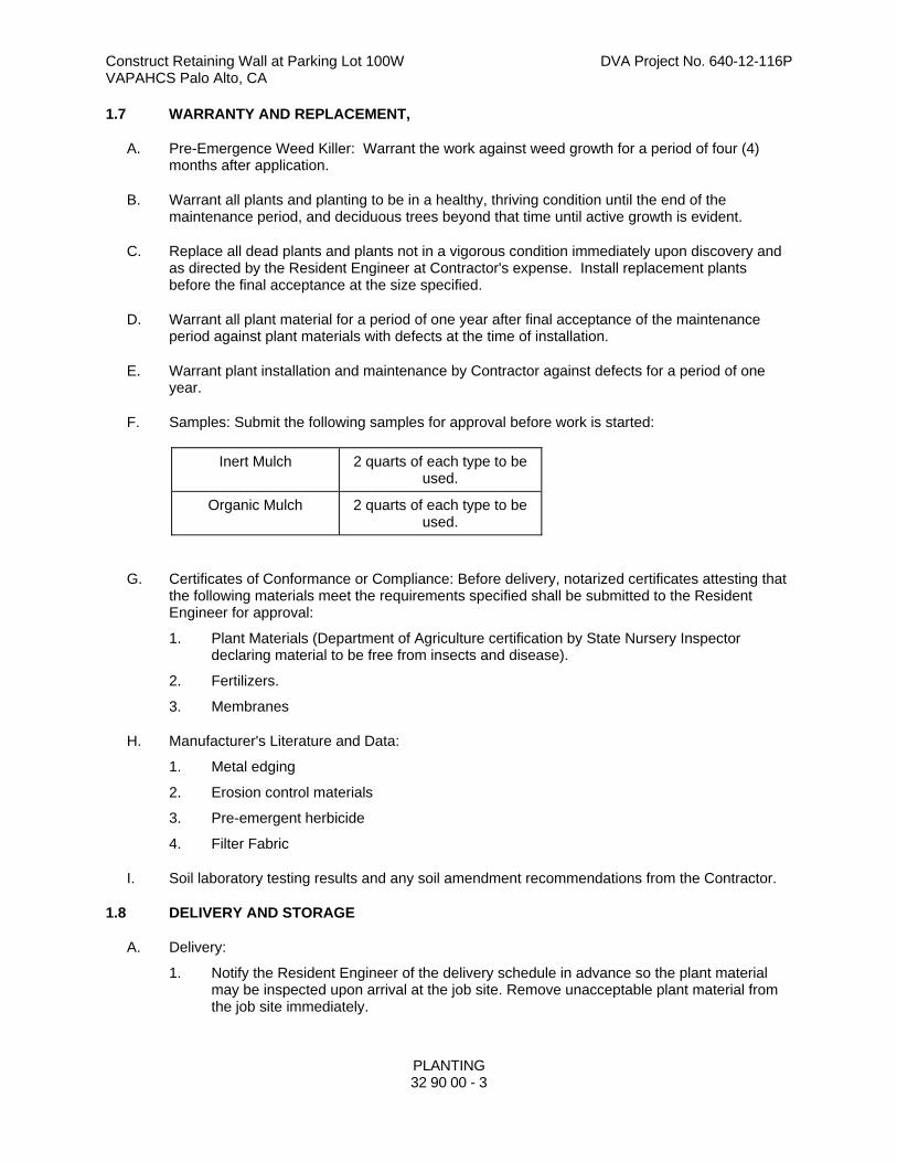
Construct Retaining Wall at Parking Lot 100W DVA Project No. 640-12-116P VAPAHCS Palo Alto, CA
PLANTING 32 90 00 - 3
1.7 WARRANTY AND REPLACEMENT,
A. Pre-Emergence Weed Killer: Warrant the work against weed growth for a period of four (4) months after application.
B. Warrant all plants and planting to be in a healthy, thriving condition until the end of the maintenance period, and deciduous trees beyond that time until active growth is evident.
C. Replace all dead plants and plants not in a vigorous condition immediately upon discovery and as directed by the Resident Engineer at Contractor's expense. Install replacement plants before the final acceptance at the size specified.
D. Warrant all plant material for a period of one year after final acceptance of the maintenance period against plant materials with defects at the time of installation.
E. Warrant plant installation and maintenance by Contractor against defects for a period of one year.
F. Samples: Submit the following samples for approval before work is started:
Inert Mulch 2 quarts of each type to be used.
Organic Mulch 2 quarts of each type to be used.
G. Certificates of Conformance or Compliance: Before delivery, notarized certificates attesting that the following materials meet the requirements specified shall be submitted to the Resident Engineer for approval:
1. Plant Materials (Department of Agriculture certification by State Nursery Inspector declaring material to be free from insects and disease).
2. Fertilizers.
3. Membranes
H. Manufacturer's Literature and Data:
1. Metal edging
2. Erosion control materials
3. Pre-emergent herbicide
4. Filter Fabric
I. Soil laboratory testing results and any soil amendment recommendations from the Contractor.
1.8 DELIVERY AND STORAGE
A. Delivery:
1. Notify the Resident Engineer of the delivery schedule in advance so the plant material may be inspected upon arrival at the job site. Remove unacceptable plant material from the job site immediately.
Construct Retaining Wall at Parking Lot 100W DVA Project No. 640-12-116P VAPAHCS Palo Alto, CA
PLANTING 32 90 00 - 4
2. Protect plants during delivery to prevent damage to root balls or desiccation of leaves. Protect trees during transport by tying in the branches and covering all exposed branches.
3. Deliver fertilizer to the site in the original, unopened containers bearing the manufacturer's warranteed chemical analysis, name, trade name or trademark, and in conformance to state and federal law.
4. During delivery: Protect seed from contamination.
B. Storage:
1. Keep fertilizer in dry storage away from contaminants.
2. Store plants not installed on the day of arrival at the site as follows:
a. Shade and protect plants from the wind when stored outside
C. Keep plants in a moist condition until planted.
1.9 LIME TREATMENT OF SUBSOIL
1. Refer to PART 3 -EXECUTION for mitigation of any lime treatment of soils.
1.10 PLANTING AND TURF INSTALLATION CONDITIONS
A. Perform planting operations after the irrigation system is installed, tested, and approved.
B. No work shall be done when the ground is too wet or in an otherwise unsuitable condition for planting. Special conditions may exist that warrants a variance. Submit a written request to the Resident Engineer stating the special conditions and proposal variance.
1.11 PLANT ESTABLISHMENT PERIOD
A. The Establishment Period for plants shall begin immediately after installation, with the approval of the Resident Engineer, and continue until the date that the Government accepts the project or phase for beneficial use and occupancy. During the Plant Establishment Period the Contractor shall:
1. Water all plants to maintain an adequate supply of moisture within the root zone. An adequate supply of moisture is the equivalent of 25 mm (1 inch) of absorbed water per week either through natural rainfall or augmented by periodic watering. Apply water at a moderate rate so as not to displace the mulch or flood the plants and turf.
2. Prune plants and replace mulch as required.
3. Replace and restore stakes, guy wires, and eroded plant saucers as required.
4. In plant beds and saucers, remove grass, weeds, and other undesired vegetation, including the root growth, before they reach a height of 75 mm (3 inches).
5. Spray with approved insecticides and fungicides to control pests and ensure plant survival in a healthy growing condition, as directed by the Resident Engineer.
6. Remove plants that die during this period and replace each plant with one of the same size and species.
Construct Retaining Wall at Parking Lot 100W DVA Project No. 640-12-116P VAPAHCS Palo Alto, CA
PLANTING 32 90 00 - 5
1.12 PLANT WARRANTY
A. All work shall be in accordance with the terms of the Paragraph, "Warranty" of FAR clause 52.246-21, including the following supplements:
1. A One Year Plant Warranty will begin on the date that the Government accepts the project or phase for beneficial use and occupancy. The Contractor shall have completed, located, and installed all plants and turf according to the plans and specifications. All plants and turf are expected to be living and in a healthy condition at the time of final inspection.
2. The Contractor will replace any dead plant materialimmediately. A one year warranty for the plants that was replaced, will begin on the day the work is completed.
3. Replacement of relocated plants, that the Contractor did not supply, is not required unless they die from improper handling and care during transplanting. Loss through Contractor negligence requires replacement in kind and size.
4. The Government will reinspect all plants at the end of the One Year Warranty. The Contractor will replace any dead, missing, or defective plant material and turf immediately. The Warranty will end on the date of this inspection provided the Contractor has complied with the work required by this specification. The Contractor shall also comply with the following requirements:
a. Replace dead, missing or defective plant material prior to final inspection.
b. Mulch and weed plant beds and saucers. Just prior to this inspection, treat these areas to a second application of approved pre-emergent herbicide.
c. From plants having been installed for one year, remove stakes, guy wires and any required tree wrappings.
d. Complete remedial measures directed by the Resident Engineer to ensure plant and turf survival.
e. Repair damage caused while making plant replacements.
1.13 APPLICABLE PUBLICATIONS
A. The publications listed below, form a part of this specification to the extent referenced. The publications are referenced in the text by basic designation only.
B. Ordinances and Regulations: All local, municipal and state laws, codes and regulations governing or relating to all portions of this work are hereby incorporated into and made a part of these Specifications. Anything contained in these Specifications shall not be construed to conflict with any of the herein listed codes, regulations or requirements of the same. However, when these Specifications and Drawings call for or describe materials, workmanship or construction of a better quality, higher standard than is required by the above mentioned codes and regulations, the provisions of these Specifications and Drawings shall take precedence. Furnish without extra charge additional materials and labor required to comply with above rules and regulations
C. American National Standards Institute (ANSI) Publications:
1. Z60.1-04 Nursery Stock
2. Z133.1-06 Tree Care Operations-Pruning, Trimming, Repairing, Maintaining, and Removing Trees and Cutting Brush- Safety Requirements
D. Hortus Third, A Concise Dictionary of Plants Cultivated in the U.S. and Canada.
Construct Retaining Wall at Parking Lot 100W DVA Project No. 640-12-116P VAPAHCS Palo Alto, CA
PLANTING 32 90 00 - 6
E. Contractor shall be familiar with and follow the State of California Model Water Ordinance, California Code of Regulations, Title 23 Waters, Division 2, Department of Water Resources, Chapter 2.7. Also, the Contractor is responsible to follow all local water ordinances and the Soil Management/Analysis Report with verifying implementation.
F. American Society for Testing and Materials (ASTM) Publications:
1. C136-06 Sieve Analysis of Fine and Coarse Aggregates
G. U. S. Department of Agriculture Federal Seed Act.
1. Rules and Regulations
H. American Wood Protection Association (AWPA):
1. C2-02 Lumber, Timbers, Bridge Ties and Mine Ties, Pressure Treatment
I. "Sunset Western Garden Book," Lane Publishing Co., Menlo Park, California; current edition.
J. Alameda Countywide Clean Water Program (ACCWP) or member agency having jurisdiction over the project work
K. US Composting Council Compost analysis Program (CAP)
L. Test Methods for the Evaluation of Composting and Compost (TMECC)
M. International Society of Arboriculture, Guide for Plant Appraisal, latest version.
N. United States Composting Council (USCC) Seal of Testing Assurance (STA) program.
O. TMECC: Refers to "Test Methods for the Examination of Composting and Compost," published by the United States Department of Agriculture and the United States Compost Council (USCC)
P. References to "Caltrans Standard Specifications" shall mean the Standard Specifications of the State of California, Business and Transportation Agency, Department of Transportation, CALTRANS.
Q. Manufacturer's recommendations
PART 2 - PRODUCTS
2.1 GENERAL
A. All plant material shall conform to the varieties specified or shown in the plant list and be true to botanical name as listed in Hortus Third.
2.2 PLANTS
A. Plants shall be nursery grown in containers and in accordance with ANSI Z60.1, except as otherwise stated in the specifications or shown on the plans. Where the drawings or specifications are in conflict with ANSI Z60.1, the drawings and specification shall prevail.
Construct Retaining Wall at Parking Lot 100W DVA Project No. 640-12-116P VAPAHCS Palo Alto, CA
PLANTING 32 90 00 - 7
B. Plant the variety, quantity and size indicated. The total quantity tabulated on the drawings are considered approximate and furnished for convenience only. Contractor shall perform his/her own plant quantity calculations and shall provide all plants shown on the Drawings.
C. Tag plants of the type or name indicated and in accordance with the standard practice recommended by the American Association of Nurserymen.
D. Install healthy, shapely and well rooted plants with no evidence of having been root-bound, restricted or deformed.
E. Take precautions to ensure that the plants will arrive at the site in proper condition for successful growth. Protect plants in transit from windburn and sunburn. Protect and maintain plants on site by proper storage and watering.
F. Substitutions will not be permitted, except as follows:
1. If proof is submitted to the Resident Engineer that any plant specified is not obtainable, a proposal will be considered for use of nearest equivalent size or variety with an equitable adjustment of contract price.
2. Substantiate and submit proof of plant availability in writing to the Resident Engineer within 10 days after the effective date of Notice to Proceed.
G. Tree Form: Trees shall have a symmetrical form as typical for the species/cultivar and growth form.
1. Central Leader for Single Trunk Trees: Trees shall have a single, relatively straight central leader and tapered trunk, free of co dominant stems and vigorous, upright branches that compete with the central leader. Preferably, the central leader should not have been headed; however, in cases where the original leader has been remove, an upright branch at least ½ the diameter of the original leader just below the pruning point shall be present.
2. Potential Main Branches: Braches shall be evenly distributed radially around and appropriately spaced vertically along the trunk, forming a generally symmetrical crown typical for the species.
3. Headed temporary branches should be distributed around and along the trunk as noted above and shall be no greater than 3/8” diameter, and no greater than ½ diameter of the trunk at point of attachment.
H. Tree Trunk
1. Trunk diameter and taper shall be sufficient so that the tree will remain vertical without the support of a nursery stake.
2. Trunk shall be free of wounds (except properly-made pruning cuts), sunburned areas, conks (fungal fruiting-bodies), wood cracks, bleeding areas, signs of boring insects, galls, cankers and/or lesions.
3. Tree trunk diameter at 6” above the soil surface shall be within the diameter range shown for each container size below, except where shown otherwise: Container Trunk Diameter in inches Soil level from Container Top 5 gallon 0.5” to 0.75” 1.25 to 2” 15 gallon 0.75” to 1.0” 1.75 to 2.75” 24” Box 1.5” to 2. 5” 2.25 to 3”
4. Tree trunks shall be undamaged and uncut with all old abrasions and cuts completely
Construct Retaining Wall at Parking Lot 100W DVA Project No. 640-12-116P VAPAHCS Palo Alto, CA
PLANTING 32 90 00 - 8
callused over. Do not prune plants prior to delivery.
I. Tree Roots
1. Trunk root collar (root crown) and large roots shall be free of circling and/or kinked roots. Contractor may be required to remove soil near the root collar in order to verify that circling and/or kinked roots are not present.
2. The tree shall be well rooted in the container. When the trunk is lifted the trunk and root system shall move as one and the rootball shall remain intact.
3. The top-most roots or root collar shall be within 1” above or below the soil surface. The soil level in the container shall be within the limits shown in above table.
4. The rootball periphery shall be free of large circling and bottom-matted roots.
5. On grafted or budded trees, there shall be no suckers from the root stock.
J. Shrubs
1. Each shrub must stand upright without support.
2. All container shrubs shall be free of girdling roots, defined as those roots greater than 1/8” diameter circling the periphery of the rootball. The top of the rootball shall be free of “Knees” (roots) protruding above the soil, and the bottom shall be free of matted roots.
K. Measure trees and shrubs with branches in normal position. Height and spread dimensions indicated refer to the main body of the plant, and not from branch tip to tip.
L. Make substitutions only when a plant (or its alternates as specified) is not obtainable and the Resident Engineer authorizes a change order providing for use of the nearest equivalent obtainable size or variety of plant having the same essential characteristics with an equitable adjustment of the contract price.
2.3 FERTILIZERS
A. Commercial fertilizer, pelleted or granular form, conform to the requirements of Chapter 7, Article 2, of the Agricultural Code of the State of California for fertilizing materials as follows:
1. Type A: 6% Nitrogen, 20% Phosphorus Acid and 20% Potash, (6-20-20).
2. Type B: 21 gram planting tablets 20% Nitrogen, 10% Phosphoric Acid and 5% Potash (20-10-5) available from Agriform or 10gm BestPacks packets 20% Nitrogen, 10% Phosphoric Acid and 5% Potash (20-10-5) available from Best Fertilizer Co.
3. Type C: Complete fertilizer 21% Nitrogen, 7% Phosphoric Acid and 14% Potash (21-7-14).
4. If commercial fertilizer having this analysis is not obtainable, other similar commercial fertilizer may be used providing it meets the approval of the Resident Engineer.
B. Maintenance Fertilizer: Type C
2.4 ORGANIC AMENDMENT FOR IN SITU SOILS (ON-GRADE):
A. Ground Redwood or Ground Fir Bark with the following properties:
Construct Retaining Wall at Parking Lot 100W DVA Project No. 640-12-116P VAPAHCS Palo Alto, CA
PLANTING 32 90 00 - 9
1. Percent Passing Sieve Designation 100 9.51 mm 3/8" 50-60 6.35 mm 1/4" 20-40 4.76 mm No. 4 0-20 2.38 mm No. 8 8 mesh Redwood Sawdust Dry bulk density, lbs. per cu. yd., 260-280 Nitrogen stabilized - dry weight basis, min. 0.4% Salinity (ECe): 4.0 maximum Organic Content: 90% minimum Reaction (pH): 4.0 minimum Ground Fir and/or Pine Bark Dry bulk density, lbs. per cu. yd., Min. 350 Nitrogen stabilized - dry weight basis, min. 0.5% Salinity (ECe): 4.0 maximum Organic Content: 90% minimum Reaction (pH): 4.0 minimum
B. Submit sample along with analytical data from an approved laboratory for degree of compliance to the Resident Engineer within two weeks after award of Contract.
2.5 COMPOSTED YARD WASTE AMENDMENT:
A. The above Ground Redwood or Ground Fir Bark or Ground Pine Bark (ORGANIC AMENDMENT FOR IN SITU SOILS) is the specified organic amendment material required. Acceptance of Composted Yard Waste Amendment in lieu of the above specified ORGANIC AMENDMENT FOR IN SITU SOILS (ON-GRADE) material will be considered if the in situ planting soil salinity and soil structure is favorable for the inclusion of recycled yard waste organic matter, as approved by the Resident Engineer. It is the Contractor's responsibility to secure test samples of both the planting soil and the proposed composted yard waste amendment (2 quart samples) and submit to Soils and Plant Laboratory for evaluation and recommendations. The composted yard waste amendment sample shall be a grab sample from the currently available material that has been tested within the last 30 days and shall include the composter's Compost Technical Data Sheet that includes lab analytical test results and directions for product use along with list of incredients. The composted yard waste amendment shall be a mixture of feedstock materials including green material consisting of chipped, shredded, or ground vegetation and mixed food waste, or clean processed recycled wood products. Single source, Biosolids (sewage waste) compost will not be acceptable.
B. Based on the Soils and Plant Laboratory evaluation, the addition of composted yard waste amendment shall not be acceptable if it creates a leaching requirement.
C. The addition of the compost shall result in a final ECe of the amended soil of less than 4.0 dS/m @ 25 degrees C. as determined in a saturation extract. Use the following table to determine the maximum allowable Ece (dS/m of saturation extract) of compost at desired use rate and allowable Ece increase.
DESIRED USE RATE MAXIMUM ALLOWABLE Ece INCREASE FROM AMENDMENT
Cu. Yds. Amendment Per 1000 Sq. Ft. for
Volume percentage of
1 dS/m 2 dS/m 3 dS/m
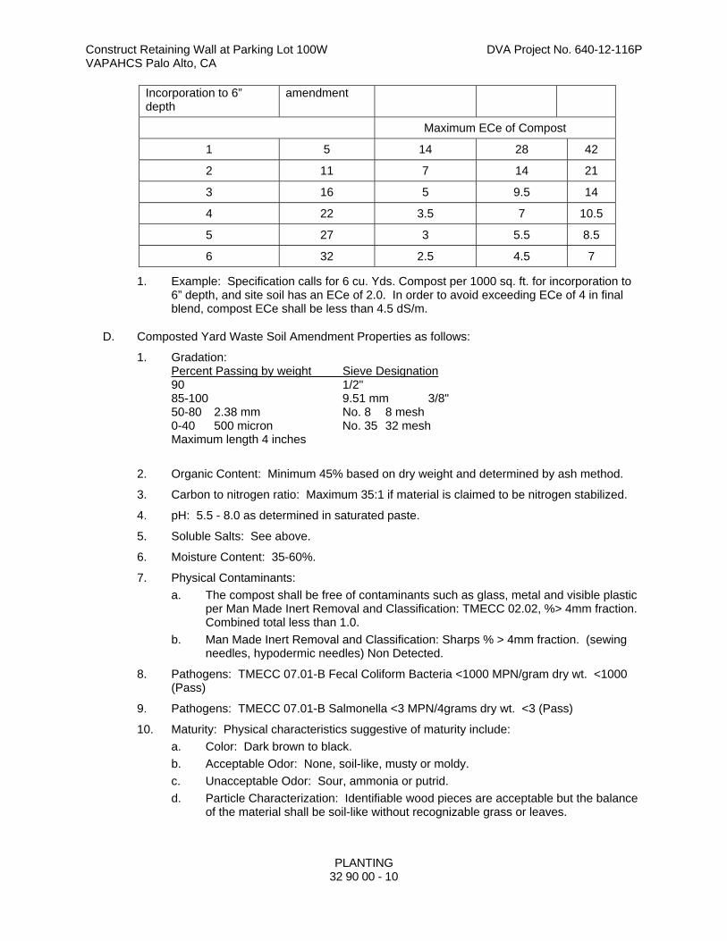
Construct Retaining Wall at Parking Lot 100W DVA Project No. 640-12-116P VAPAHCS Palo Alto, CA
PLANTING
32 90 00 - 10
Incorporation to 6” depth
amendment
Maximum ECe of Compost
1 5 14 28 42
2 11 7 14 21
3 16 5 9.5 14
4 22 3.5 7 10.5
5 27 3 5.5 8.5
6 32 2.5 4.5 7
1. Example: Specification calls for 6 cu. Yds. Compost per 1000 sq. ft. for incorporation to 6” depth, and site soil has an ECe of 2.0. In order to avoid exceeding ECe of 4 in final blend, compost ECe shall be less than 4.5 dS/m.
D. Composted Yard Waste Soil Amendment Properties as follows:
1. Gradation: Percent Passing by weight Sieve Designation 90 1/2" 85-100 9.51 mm 3/8" 50-80 2.38 mm No. 8 8 mesh 0-40 500 micron No. 35 32 mesh Maximum length 4 inches
2. Organic Content: Minimum 45% based on dry weight and determined by ash method.
3. Carbon to nitrogen ratio: Maximum 35:1 if material is claimed to be nitrogen stabilized.
4. pH: 5.5 - 8.0 as determined in saturated paste.
5. Soluble Salts: See above.
6. Moisture Content: 35-60%.
7. Physical Contaminants:
a. The compost shall be free of contaminants such as glass, metal and visible plastic per Man Made Inert Removal and Classification: TMECC 02.02, %> 4mm fraction. Combined total less than 1.0.
b. Man Made Inert Removal and Classification: Sharps % > 4mm fraction. (sewing needles, hypodermic needles) Non Detected.
8. Pathogens: TMECC 07.01-B Fecal Coliform Bacteria <1000 MPN/gram dry wt. <1000 (Pass)
9. Pathogens: TMECC 07.01-B Salmonella <3 MPN/4grams dry wt. <3 (Pass)
10. Maturity: Physical characteristics suggestive of maturity include:
a. Color: Dark brown to black.
b. Acceptable Odor: None, soil-like, musty or moldy.
c. Unacceptable Odor: Sour, ammonia or putrid.
d. Particle Characterization: Identifiable wood pieces are acceptable but the balance of the material shall be soil-like without recognizable grass or leaves.
Construct Retaining Wall at Parking Lot 100W DVA Project No. 640-12-116P VAPAHCS Palo Alto, CA
PLANTING
32 90 00 - 11
e. TMECC 07.01-A Germination and Vigor, % Relative to Positive Control for Seed Emergence and Seedling Vigor: 80 or above.
E. Submit planting soil and composted yard waste amendment samples along with laboratory report from Soils and Plant Laboratory for degree of compliance as specified above and composter's Compost Technical Data Sheet that includes lab analytical test results and directions for product use along with list of ingredients to the Resident Engineer a minimum of 3 weeks prior to beginning soil prep. The laboratory report shall include recommendations for adjusting fertilizer and amendment quantities. Upon approval of the Laboratory's report by the Resident Engineer, the recommendations in the report shall become a part of the Specifications and the quantities of soil amendment and fertilizer shall be adjusted to conform with the report at no additional cost to the owner.
2.6 IRON SULFATE
A. Type: Dry form.
2.7 PLANT BACKFILL
A. Except for acid loving plants (Azaleas, Rhododendrons, Ferns, Camellias, etc.), use a mixture of 2 parts soil from the hole, and 1 part amendment with iron added at the following rates:
1. Size Rate 1 gallon can plants iron, 1/4 cup 5 gallon can plants iron, 1/3 cup 15 gallon can plants iron, 1/2 cup 24" box and larger iron, 1 cup
2. Mix the iron, amendment and soil thoroughly for use only in the top 8 inches of backfill around plants. For acid loving plants, mixture to be 1/2 soil from the hole and 1/2 amendment only in the top 8 inches.
2.8 MULCH
A. Organic Mulch: Fir tree or pine tree bark, dark gray or black in color; 3/4-inch to 1-inch size.
B. Submit samples of organic mulch to the Resident Engineer for approval within two weeks of award of Contract. Resubmit until acceptable to Resident Engineer, at no extra cost.
2.9 TREE SUPPORT POLES
A. Type: Peeled lodge pole pine logs, clean, smooth, new, and sized as follows:
1. Two-inch (2") diameter by eight feet (8') long for trees less than 8' high and 1" caliper.
2. Three-inch (3") diameter by eight to ten feet (8' - 10') long for trees greater than 8' high and 1" caliper.
2.10 TIES
A. Rubber strap, 24-inch minimum length without sharp edges adjacent to trunk.
Construct Retaining Wall at Parking Lot 100W DVA Project No. 640-12-116P VAPAHCS Palo Alto, CA
PLANTING
32 90 00 - 12
2.11 TREE GUYING:
A. For trees up to 3" caliper, 3/16" galvanized steel cable, with rubber tree collar, 12" minimum long, and secured with cable clamp, and attached to anchor for below-grade location.
B. For trees 3" to 6" caliper, 1/8" galvanized steel cable with rubber tree collar, 21" minimum long, and secured with cable clamp, 3" take-up eye to eye turnbuckle, and attached to anchor for below-grade location.
C. For trees in raised planters, provide expansion bolt anchors into concrete planter walls and secure cables to anchor bolts.
2.12 TREE ROOT BARRIER
A. Root Barrier shall be black injection molded panels of .080" wall thickness in modules 24d" long by 18"deep manufactured with a minimum 50% post consumer recycled polypropylene plastic with added ultraviolet inhibitors, recyclable
B. Each panel shall have not less than 4 molded integral vertical root deflecting ribs of at least 0.06" thickness protruding 1/2" at 90 degrees from interior of the barrier panel, spaced 6" apart. A double top edge consisting of two parallel, integral, horizontal ribs at the top of the panel of a minimum 0.06" thickness 3/8" wide and 1/4" apart. A minimum of 9 anti-lift tabs consisting of integral horizontal ridges of a minimum 0.06" thickness.
C. Panels shall have an instant assembly system by sliding one panel into another.
2.13 PLANTING SOIL (TOPSOIL):
A. Planting soil is defined as screened imported soil. Satisfactory planting soil shall be free of subsoil, clay, lumps, stones, and other objects over 2" in diameter, and without weeds, roots, and other objectionable material.
2.14 IMPORTED PLANTING SOIL (TOPSOIL):
A. Imported planting soil shall be fertile, friable, natural, productive soil containing a normal amount of humus, and shall be capable of sustaining healthy plant life. Planting soil shall be free of subsoil, heavy or stiff clay, rocks, gravel, brush, roots, weeds, noxious seeds, sticks, trash, and other deleterious substances. Soil shall not be infested with nematodes or with other noxious animal life or toxic substances. Soil shall be obtained from well-drained, arable land, and shall be of an even texture. Soil shall not be taken from areas on which are growing any noxious weeds such as Morning Glory, Sorrel, or Bermuda Grass.
B. Imported planting soil shall have a pH value of between 6.0 and 7.5, a boron concentration of the saturation extract of less than 1 ppm, salinity of the saturation extract at 25 degrees C. of less than 4.0 millimoles, and a sodium absorption rate (SAR) of less than 8.
C. The silt and clay content of imported planting soil shall not exceed that of the existing soil it is to be placed over. It shall be a "Sandy Loam" as classified in accordance with USDA Standards with a combined total of between 25%to 40% Clay and Silt. Provide existing site soil sample analysis report for comparison with the imported soil report.
D. Make the site of the source of supply of planting soil available to the Resident Engineer for observation and approval prior to any hauling or placing of soil. In addition, submit for approval a 1-quart sample of soil, together with a standard soil analysis report by an accredited soils
Construct Retaining Wall at Parking Lot 100W DVA Project No. 640-12-116P VAPAHCS Palo Alto, CA
PLANTING
32 90 00 - 13
analyst showing chemical analysis stating source, fertility, agricultural suitability and particle size distribution of the soil. Deliver the sample to the Resident Engineer two weeks before starting the contemplated hauling of the soil. Following approval of the sample, provide a one-half cubic yard sample, which shall be stored at the site of work for comparison with subsequent loads of soil. The comparison sample shall be protected by a cover until the furnishing of all soil has been completed and accepted. Should the soil submittal lack certain requirements which can be added to the soil, the Resident Engineer will consider a request by the Contractor to amend the soil as recommended by the Soils Analyst at the Contractor's expense.
2.15 PRE-EMERGENCE WEED KILLER
A. Clean non-staining as recommended by a licensed pest control specialist.
2.16 FILTER FABRIC
A. Needle punched nonwoven geotextile Filter Fabric composed of polypropylene fibers, which are formed into a stable network such that the fibers retain their relative position. Inert to biological degradation and resists naturally encountered chemicals, alkalis, and acids weighing 18 grams per square meter. Meets Aashto M288-06 Class 3 for elongation > 50%.
2.17 PIPE:
A. Polyvinyl Chloride (PVC) pipe and pipe fittings shall meet extra strength minimum of SDR-35 of the requirements of ASTM Specification D3034.
B. Perforated and non-perforated corrugated polyethylene pipe, 3- to 10-inch diameter, shall meet the requirements of ASTM D883 and ASTM F412, and shall conform to Section 68 of the Standard Specifications.
1. Corrugated polyethylene pipe fittings shall comply with all requirements of AASHTO M-252-85I for 3- to 10-inch diameter pipe. Couplings shall be split or snap-on type for perforated pipe and split couplings with gaskets for non-perforated pipe. Cutting pipe with integral couplings will not be allowed.
2. Corrugated polyethylene pipe and fittings manufactured by Advanced Drainage Systems, Inc., shall be considered the standard to determine compliance to this specification.
C. Inspection Tube Cap
1. Paint cap one coat chocolate-brown color using Flat, exterior grade latex paint as accepted by Resident Engineer.
2.18 PERMEABLE BACKFILL (FILTER ROCK)
A. Permeable backfill used in subsurface drain installations to be Class 2 permeable material in conformance with Section 68 "Subsurface Drains" of the Caltrans Standard Specifications; gradation to 3/4" maximum size. Submit Sample for approval.
2.19 EROSION CONTROL NETTING
A. New, with a uniform, open plain-weave, flame-retardant mesh. The mesh shall be [natural brown-tan] [dyed green] and made from unbleached single jute yarn. The yarn shall be of loosely twisted construction and shall not vary in thickness by more than one-half its normal diameter. Furnish jute mesh in rolled strips to meet the following requirements:
1. Width: 48 inches, with a tolerance of one-inch wider or narrower.
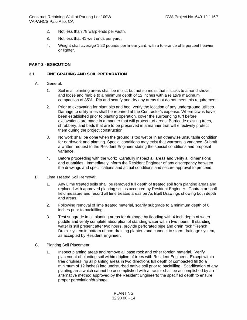
Construct Retaining Wall at Parking Lot 100W DVA Project No. 640-12-116P VAPAHCS Palo Alto, CA
PLANTING
32 90 00 - 14
2. Not less than 78 warp ends per width.
3. Not less that 41 weft ends per yard.
4. Weight shall average 1.22 pounds per linear yard, with a tolerance of 5 percent heavier or lighter.
PART 3 - EXECUTION
3.1 FINE GRADING AND SOIL PREPARATION
A. General:
1. Soil in all planting areas shall be moist, but not so moist that it sticks to a hand shovel, and loose and friable to a minimum depth of 12 inches with a relative maximum compaction of 85%. Rip and scarify and dry any areas that do not meet this requirement.
2. Prior to excavating for plant pits and bed, verify the location of any underground utilities. Damage to utility lines shall be repaired at the Contractor's expense. Where lawns have been established prior to planting operation, cover the surrounding turf before excavations are made in a manner that will protect turf areas. Barricade existing trees, shrubbery, and beds that are to be preserved in a manner that will effectively protect them during the project construction
3. No work shall be done when the ground is too wet or in an otherwise unsuitable condition for earthwork and planting. Special conditions may exist that warrants a variance. Submit a written request to the Resident Engineer stating the special conditions and proposal variance.
4. Before proceeding with the work: Carefully inspect all areas and verify all dimensions and quantities. Immediately inform the Resident Engineer of any discrepancy between the drawings and specifications and actual conditions and secure approval to proceed.
B. Lime Treated Soil Removal:
1. Any Lime treated soils shall be removed full depth of treated soil from planting areas and replaced with approved planting soil as accepted by Resident Engineer. Contractor shall field measure and record all lime treated areas on As Built Drawings showing both depth and areas.
2. Following removal of lime treated material, scarify subgrade to a minimum depth of 6 inches prior to backfilling.
3. Test subgrade in all planting areas for drainage by flooding with 4 inch depth of water puddle and verify complete absorption of standing water within two hours. If standing water is still present after two hours, provide perforated pipe and drain rock "French Drain" system in bottom of non-draining planters and connect to storm drainage system, as accepted by Resident Engineer.
C. Planting Soil Placement:
1. Inspect planting areas and remove all base rock and other foreign material. Verify placement of planting soil within dripline of trees with Resident Engineer. Except within tree driplines, rip all planting areas in two directions full depth of compacted fill (to a minimum of 12 inches) into undisturbed native soil prior to backfilling. Scarification of any planting area which cannot be accomplished with a tractor shall be accomplished by an alternative method approved by the Resident Engineerto the specified depth to ensure proper percolation/drainage.
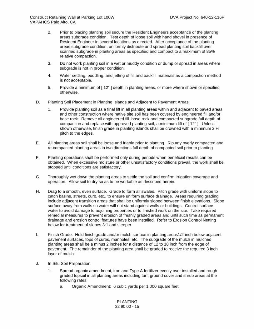
Construct Retaining Wall at Parking Lot 100W DVA Project No. 640-12-116P VAPAHCS Palo Alto, CA
PLANTING
32 90 00 - 15
2. Prior to placing planting soil secure the Resident Engineers acceptance of the planting areas subgrade condition. Test depth of loose soil with hand shovel in presence of Resident Engineer in several locations as directed. After acceptance of the planting areas subgrade condition, uniformly distribute and spread planting soil backfill over scarified subgrade in planting areas as specified and compact to a maximum of 85% relative compaction.
3. Do not work planting soil in a wet or muddy condition or dump or spread in areas where subgrade is not in proper condition.
4. Water settling, puddling, and jetting of fill and backfill materials as a compaction method is not acceptable.
5. Provide a minimum of [ 12” ] depth in planting areas, or more where shown or specified otherwise.
D. Planting Soil Placement in Planting Islands and Adjacent to Pavement Areas:
1. Provide planting soil as a final lift in all planting areas within and adjacent to paved areas and other construction where native site soil has been covered by engineered fill and/or base rock. Remove all engineered fill, base rock and compacted subgrade full depth of compaction and replace with approved planting soil, a minimum lift of [ 12” ]. Unless shown otherwise, finish grade in planting islands shall be crowned with a minimum 2 % pitch to the edges.
E. All planting areas soil shall be loose and friable prior to planting. Rip any overly compacted and re-compacted planting areas in two directions full depth of compacted soil prior to planting.
F. Planting operations shall be performed only during periods when beneficial results can be obtained. When excessive moisture or other unsatisfactory conditions prevail, the work shall be stopped until conditions are satisfactory.
G. Thoroughly wet down the planting areas to settle the soil and confirm irrigation coverage and operation. Allow soil to dry so as to be workable as described herein.
H. Drag to a smooth, even surface. Grade to form all swales. Pitch grade with uniform slope to catch basins, streets, curb, etc., to ensure uniform surface drainage. Areas requiring grading include adjacent transition areas that shall be uniformly sloped between finish elevations. Slope surface away from walls so water will not stand against walls or buildings. Control surface water to avoid damage to adjoining properties or to finished work on the site. Take required remedial measures to prevent erosion of freshly graded areas and until such time as permanent drainage and erosion control features have been installed. Refer to Erosion Control Netting below for treatment of slopes 3:1 and steeper.
I. Finish Grade: Hold finish grade and/or mulch surface in planting areas1/2-inch below adjacent pavement surfaces, tops of curbs, manholes, etc. The subgrade of the mulch in mulched planting areas shall be a minus 2 inches for a distance of 12 to 18 inch from the edge of pavement. The remainder of the planting area shall be graded to receive the required 3 inch layer of mulch.
J. In Situ Soil Preparation:
1. Spread organic amendment, iron and Type A fertilizer evenly over installed and rough graded topsoil in all planting areas including turf, ground cover and shrub areas at the following rates:
a. Organic Amendment: 6 cubic yards per 1,000 square feet

Construct Retaining Wall at Parking Lot 100W DVA Project No. 640-12-116P VAPAHCS Palo Alto, CA
PLANTING
32 90 00 - 16
b. Fertilizer: Type A (6-20-20) at 20 lbs. per 1,000 square feet.
c. Iron Sulfate: 10 lbs. per 1,000 square feet
2. Rototill above additives into soil 6 to 8 inches deep. Keep iron sulfate off pavement and other surfaces to prevent rust staining. Correct all rust damage to work.
3. Planting soil shall have a pH range of 6.5 to 7.5.
K. After the rototill work, float areas to a smooth, uniform grade as indicated on the drawings. Slope all planting areas to drain. Roll, scarify, rake and level as necessary to obtain true, even planting surfaces. Remove rocks, sticks and debris 1 inch and larger in size in turf areas and 2 inches or larger in shrub and ground cover areas. Secure approval of the grade by the Resident Engineer before any planting.
3.2 EROSION CONTROL NETTING
A. Verify finished grades and provide Jute Mesh and single grind Redwood bark mulch on all slopes 3:1 and steeper as accepted by the Resident Engineer. Install jute mesh loosely up and down the slope in accordance with manufacturer's specifications and as follows. Fit the soil surface contour and hold in place with 12-inch long, 11-gauge (minimum) steel wire staples driven vertically into the soil at 18- to 24-inch spacing. Jute mesh strips shall overlap along all edges at least 6 inches. Ends of side strips shall be buried into the soil at least 6 inches. Drive staples along edges to securely anchor mesh to ground.
3.3 ALUMINUM EDGING
A. Install in continuous strips as indicated and in accordance with manufacturer's recommendations with stakes spaced 48 inches on center maximum and at all joints.
3.4 TREE AND SHRUB PLANTING
A. Mark tree and shrub locations on site using stakes, gypsum or similar approved means and secure location approval by the Resident Engineer before plant holes are dug. Review location of plants in relationship to irrigation heads and adjust location(s) that interfere with the function of the spray heads as accepted by the Resident Engineer prior to planting.
B. Test drainage of plant pits by filling with water (minimum 6"). The retention of water in planting beds and plant pits for more than two (2) hours shall be brought to the attention of the Resident Engineer. If rock, underground construction work, tree roots, poor drainage, or other obstructions are encountered in the excavation of plant pits, alternate locations may be selected by Resident Engineer.
C. Excavate tree, shrub and vine pits as follows (Note square Tree Pit pattern required below):
1. Excavation for Width Depth Boxed Trees Box + 24" Box depth Canned Trees (15 gc) Can + 18" Can depth Canned Shrubs/Vines (1 or 5 gc) Can + 12" Can depth
D. Break and loosen the sides and bottom of the pit to ensure root penetration and water test hole for drainage as required above.
E. Backfill plant holes with mix as specified, free from rocks, clods or lumpy material. Backfill native soil free of soil amendments under rootball and foot tamp to prevent settlement. Backfill remainder of the hole with soil mix and place plant tablets or packets (Type B fertilizer) 3 inches below finish grade and 1/2-inch from roots at the following rates:

Construct Retaining Wall at Parking Lot 100W DVA Project No. 640-12-116P VAPAHCS Palo Alto, CA
PLANTING
32 90 00 - 17
1. Size Rate 1 gallon can plant - 1 tablet or packet 5 gallon can plant 3 tablets or packet 15 gallon can plant 6 tablets or packet 24-inch box plant - 6 tablets or packet 36-inch box plant - 8 tablets or packet
F. Carefully remove and set plants without damaging the rootball. Superficially cut edge roots vertically on three sides. Remove bottom of plant boxes before planting. Remove sides of boxes after positioning the plant and partially backfilling.
G. Set plants in backfill with top of the rootball 2 inches above finished grade. Backfill remainder of hole and soak thoroughly by jetting with a hose and pipe section. Water backfill until saturated the full depth of the hole.
H. Build 6" high watering basin berms around trees and shrubs to drain through rootball. Basins are not required around trees in turf areas.
I. Stake and/or guy trees as detailed and noted herein. Drive stake(s) until solid (at least 12" beyond bottom of rootball) and remove excess stake protruding above top tree tie to prevent rubbing against branches. Avoid driving stakes through rootball. If subgrade does not accept stakes to a stable degree, delete stakes and guy the trees as specified herein and as detailed. Locate tree ties to avoid contact with tree branches. Locate top tie at tree flex point.
J. Where tree guying is required, Guy Trees using 3 cables with below grade anchors and rubber collars secured with cable clamps.
K. Remove any soil from top of plant rootballs and secure Resident Engineer's approval of rootball height prior to mulching.
L. After approval of rootball height, install mulch as required below.
3.5 GROUND COVER PLANTING
A. Plant in neat, straight, parallel and staggered rows as indicated on plan. Plant first row one-half required ground cover spacing behind adjacent curbs, structures, or other plant bed limits. Plant ground cover to edge of water basins of adjacent trees and shrubs.
3.6 MULCH
A. Except where rock mulch is required, mulch all tree, shrub and ground cover areas with organic mulch to a 3-inch depth, except adjacent to walkways where soil grade is 2 inches below top of pavement, mulch shall be 2 inches deep, and 2-inches deep where planting ground cover plants from flats. Hold bark mulch away from base (trunk) of plant 4" or as directed by the Resident Engineer. Individual trees and/or shrubs planted in non-irrigated areas shall, at minimum, receive bark mulch over their watering basin and berm. No mulch is required around trees in turf areas, bioswales, or biodetention basins.
3.7 ROOT BARRIER
A. Install in linear fashion along and adjacent to the edges of the planting area as detailed or, if not shown, in accordance with manufacturer's recommendations. Set top of barrier approximately ½-inch above finished soil surface to allow concealment with mulch, as accepted by Resident Engineer.

Construct Retaining Wall at Parking Lot 100W DVA Project No. 640-12-116P VAPAHCS Palo Alto, CA
PLANTING
32 90 00 - 18
3.8 PRE-EMERGENCE WEED KILLER
A. Apply pre-emergence weed killer in all areas to receive ground cover planting. Work shall be done under the supervision of a person licensed by the State of California as a pest control applicator and holding a qualified applicator license or a Qualified Applicator Certificate. Obtain approval of the finish grades prior to applying weed killer and coordinate planting and watering with the pest control specialist prior to planting. Take care to keep weed killer off areas to be seeded.
3.9 WATERING
A. Water trees, shrubs and ground cover immediately after planting. Apply water to plants as often and in sufficient amount as conditions may require to keep the plants in a healthy vigorous growing condition until completion of the Contract. Do supplemental hand watering of trees and shrubs during the first 3 weeks of plant establishment.
3.10 RESTORATION AND CLEAN-UP
A. Where existing or new turf areas have been damaged or scarred during planting and construction operations, restore disturbed area to their original condition. Keep at least one paved pedestrian access route and one paved vehicular access route to each building clean at all times. In areas where planting and turf work have been completed, clear the area of all debris, spoil piles, and containers. Clear all other paved areas when work in adjacent areas is completed. Remove all debris, rubbish and excess material from the station.
3.11 ENVIRONMENTAL PROTECTION
A. All work and Contractor operations shall comply with the requirements of Section 01 57 19, TEMPORARY ENVIRONMENTAL CONTROLS.
- - - E N D - - -
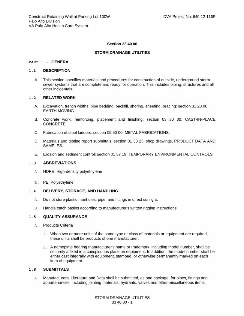
Construct Retaining Wall at Parking Lot 100W DVA Project No. 640-12-116P Palo Alto Division VA Palo Alto Health Care System
STORM DRAINAGE UTILITIES 33 40 00 - 1
Section 33 40 00
STORM DRAINAGE UTILITIES
PART 1 - GENERAL
1.1 DESCRIPTION
A. This section specifies materials and procedures for construction of outside, underground storm sewer systems that are complete and ready for operation. This includes piping, structures and all other incidentals.
1.2 RELATED WORK
A. Excavation, trench widths, pipe bedding, backfill, shoring, sheeting, bracing: section 31 20 00, EARTH MOVING.
B. Concrete work, reinforcing, placement and finishing: section 03 30 00, CAST-IN-PLACE CONCRETE.
C. Fabrication of steel ladders: section 05 50 00, METAL FABRICATIONS.
D. Materials and testing report submittals: section 01 33 23, shop drawings, PRODUCT DATA AND SAMPLES.
E. Erosion and sediment control: section 01 57 19, TEMPORARY ENVIRONMENTAL CONTROLS.
1.3 ABBREVIATIONS
A. HDPE: High-density polyethylene
B. PE: Polyethylene
1.4 DELIVERY, STORAGE, AND HANDLING
A. Do not store plastic manholes, pipe, and fittings in direct sunlight.
B. Handle catch basins according to manufacturer's written rigging instructions.
1.5 QUALITY ASSURANCE
A. Products Criteria
1. When two or more units of the same type or class of materials or equipment are required, these units shall be products of one manufacturer.
2. A nameplate bearing manufacturer's name or trademark, including model number, shall be securely affixed in a conspicuous place on equipment. In addition, the model number shall be either cast integrally with equipment, stamped, or otherwise permanently marked on each item of equipment.
1.6 SUBMITTALS
A. Manufacturers’ Literature and Data shall be submitted, as one package, for pipes, fittings and appurtenances, including jointing materials, hydrants, valves and other miscellaneous items.

Construct Retaining Wall at Parking Lot 100W DVA Project No. 640-12-116P Palo Alto Division VA Palo Alto Health Care System
STORM DRAINAGE UTILITIES 33 40 00 - 2
1.7 APPLICABLE PUBLICATIONS
A. The publications listed below form a part of this specification to the extent referenced. The publications are referenced in the text by the basic designation only.
B. American Society for Testing and Materials (ASTM):
A185/A185M-07 ......................... Steel Welded Wire Reinforcement, Plain, for Concrete
A242/A242M-04(2009) ............... High-Strength Low-Alloy Structural Steel
A536-84(2009) ........................... Ductile Iron Castings
A615/A615M-09b ....................... Deformed and Plain Carbon-Steel Bars for Concrete Reinforcement
A760/A760M-10 ......................... Corrugated Steel Pipe, Metallic-Coated for Sewers and Drains
A798/A798M-07 ......................... Installing Factory-Made Corrugated Steel Pipe for Sewers and Other Applications
A849-10 ...................................... Post-Applied Coatings, Paving, and Linings for Corrugated Steel Sewer and Drainage Pipe
A929/A929M-01(2007) ............... Steel Sheet, Metallic-Coated by the Hot-Dip Process for Corrugated Steel Pipe
B745/B745M-97(2005) ............... Corrugated Aluminum Pipe for Sewers and Drains
B788/B788M-09 ......................... Installing Factory-Made Corrugated Aluminum Culverts and Storm Sewer Pipe
C14-07 ....................................... Non-reinforced Concrete Sewer, Storm Drain, and Culvert Pipe
C33/C33M-08 ............................. Concrete Aggregates
C76-11 ....................................... Reinforced Concrete Culvert, Storm Drain, and Sewer Pipe
C139-10 ..................................... Concrete Masonry Units for Construction of Catch Basins and Manholes
C150/C150M-11 ......................... Portland Cement
C443-10 ..................................... Joints for Concrete Pipe and Manholes, Using Rubber Gaskets
C478-09 ..................................... Precast Reinforced Concrete Manhole Sections
C506-10b ................................... Reinforced Concrete Arch Culvert, Storm Drain, and Sewer Pipe
C507-10b ................................... Reinforced Concrete Elliptical Culvert, Storm Drain, and Sewer Pipe
C655-09 ..................................... Reinforced Concrete D-Load Culvert, Storm Drain, and Sewer Pipe

Construct Retaining Wall at Parking Lot 100W DVA Project No. 640-12-116P Palo Alto Division VA Palo Alto Health Care System
STORM DRAINAGE UTILITIES 33 40 00 - 3
C857-07 ..................................... Minimum Structural Design Loading for Underground Precast Concrete Utility Structures
C891-09 ..................................... Installation of Underground Precast Concrete Utility Structures
C913-08 ..................................... Precast Concrete Water and Wastewater Structures
C923-08 ..................................... Resilient Connectors Between Reinforced Concrete Manhole Structures, Pipes, and Laterals
C924-02(2009) ........................... Testing Concrete Pipe Sewer Lines by Low-Pressure Air Test Method
C990-09 ..................................... Joints for Concrete Pipe, Manholes, and Precast Box Sections Using Preformed Flexible Joint Sealants
C1103-03(2009) ......................... Joint Acceptance Testing of Installed Precast Concrete Pipe Sewer Lines
C1173-08 ................................... Flexible Transition Couplings for Underground Piping Systems
C1433-10 ................................... Precast Reinforced Concrete Monolithic Box Sections for Culverts, Storm Drains, and Sewers
C1479-10 ................................... Installation of Precast Concrete Sewer, Storm Drain, and Culvert Pipe Using Standard Installations
D448-08 ..................................... Sizes of Aggregate for Road and Bridge Construction
D698-07e1 ................................. Laboratory Compaction Characteristics of Soil Using Standard Effort (12 400 ft-lbf/ft3 (600 kN-m/m3))
D1056-07 ................................... Flexible Cellular Materials—Sponge or Expanded Rubber
D1785-06 ................................... Poly(Vinyl Chloride) (PVC) Plastic Pipe, Schedules 40, 80, and 120
D2321-11 ................................... Underground Installation of Thermoplastic Pipe for Sewers and Other Gravity-Flow Applications
D2751-05 ................................... Acrylonitrile-Butadiene-Styrene (ABS) Sewer Pipe and Fittings
D2774-08 ................................... Underground Installation of Thermoplastic Pressure Piping
D3034-08 ................................... Type PSM Poly(Vinyl Chloride) (PVC) Sewer Pipe and Fittings
D3350-10 ................................... Polyethylene Plastics Pipe and Fittings Materials
D3753-05e1 ............................... Glass-Fiber-Reinforced Polyester Manholes and Wetwells
D4101-11 ................................... Polypropylene Injection and Extrusion Materials
D5926-09 ................................... Poly (Vinyl Chloride) (PVC) Gaskets for Drain, Waste, and Vent (DWV), Sewer, Sanitary, and Storm Plumbing Systems
F405-05 ...................................... Corrugated Polyethylene (PE) Pipe and Fittings
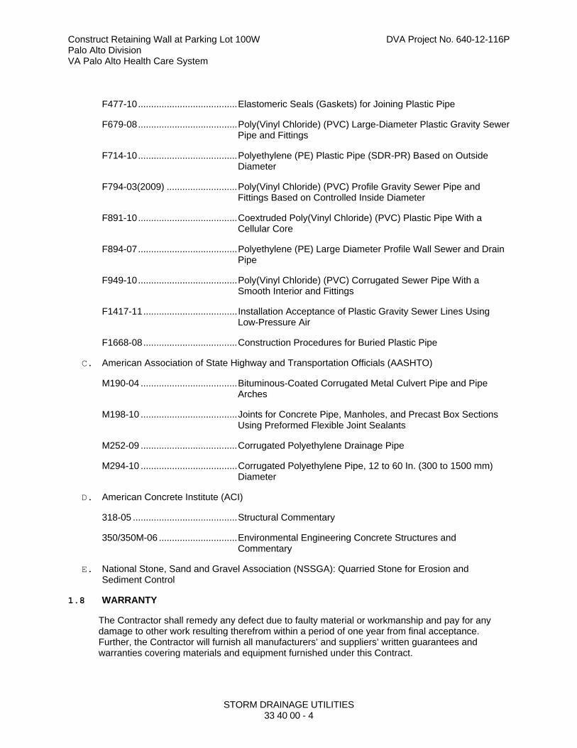
Construct Retaining Wall at Parking Lot 100W DVA Project No. 640-12-116P Palo Alto Division VA Palo Alto Health Care System
STORM DRAINAGE UTILITIES 33 40 00 - 4
F477-10 ...................................... Elastomeric Seals (Gaskets) for Joining Plastic Pipe
F679-08 ...................................... Poly(Vinyl Chloride) (PVC) Large-Diameter Plastic Gravity Sewer Pipe and Fittings
F714-10 ...................................... Polyethylene (PE) Plastic Pipe (SDR-PR) Based on Outside Diameter
F794-03(2009) ........................... Poly(Vinyl Chloride) (PVC) Profile Gravity Sewer Pipe and Fittings Based on Controlled Inside Diameter
F891-10 ...................................... Coextruded Poly(Vinyl Chloride) (PVC) Plastic Pipe With a Cellular Core
F894-07 ...................................... Polyethylene (PE) Large Diameter Profile Wall Sewer and Drain Pipe
F949-10 ...................................... Poly(Vinyl Chloride) (PVC) Corrugated Sewer Pipe With a Smooth Interior and Fittings
F1417-11 .................................... Installation Acceptance of Plastic Gravity Sewer Lines Using Low-Pressure Air
F1668-08 .................................... Construction Procedures for Buried Plastic Pipe
C. American Association of State Highway and Transportation Officials (AASHTO)
M190-04 ..................................... Bituminous-Coated Corrugated Metal Culvert Pipe and Pipe Arches
M198-10 ..................................... Joints for Concrete Pipe, Manholes, and Precast Box Sections Using Preformed Flexible Joint Sealants
M252-09 ..................................... Corrugated Polyethylene Drainage Pipe
M294-10 ..................................... Corrugated Polyethylene Pipe, 12 to 60 In. (300 to 1500 mm) Diameter
D. American Concrete Institute (ACI)
318-05 ........................................ Structural Commentary
350/350M-06 .............................. Environmental Engineering Concrete Structures and Commentary
E. National Stone, Sand and Gravel Association (NSSGA): Quarried Stone for Erosion and Sediment Control
1.8 WARRANTY
The Contractor shall remedy any defect due to faulty material or workmanship and pay for any damage to other work resulting therefrom within a period of one year from final acceptance. Further, the Contractor will furnish all manufacturers’ and suppliers’ written guarantees and warranties covering materials and equipment furnished under this Contract.
Construct Retaining Wall at Parking Lot 100W DVA Project No. 640-12-116P Palo Alto Division VA Palo Alto Health Care System
STORM DRAINAGE UTILITIES 33 40 00 - 5
PART 2 - PRODUCTS
2.1 FACTORY-ASSEMBLED PRODUCTS
A. Standardization of components shall be maximized to reduce spare part requirements. The Contractor shall guarantee performance of assemblies of components, and shall repair or replace elements of the assemblies as required to deliver specified performance of the complete assembly.
2.2 PE PIPE AND FITTINGS
A. Corrugated PE drainage pipe and fittings, NPS 3 to NPS 10 (DN 80 to DN 250); ASTM F714, SDR 21 with smooth waterway for coupling joints.
1. Soil-tight Couplings: AASHTO M252, corrugated, matching tube and fittings.
B. Corrugated PE pipe and fittings, NPS 12 to NPS 60 (DN 300 to DN 1500); AASHTO M294, Type S, with smooth waterway for coupling joints. Pipe shall be produced from PE certified by the resin producer as meeting the requirements of ASTM D3350, minimum cell class 335434C.
1. Soil-tight Couplings: AASHTO M252, corrugated, matching tube and fittings.
2. Water tight joints shall be made using a PVC or PE coupling and rubber gaskets as recommended by the pipe manufacturer. Rubber gaskets shall conform to ASTM F477. Soil tight joints shall conform to requirements in AASHTO HB-17, Division II, for soil tightness and shall be as recommended by the manufacturer.
C. PVC Type PSM Sewer Piping
1. Pipe: ASTM D3034, SDR 35, PVC Type PSM sewer pipe with bell-and-spigot ends.
2. Fittings: ASTM D3034, PVC with bell ends.
3. Gaskets: ASTM F477, elastomeric seals.
2.3 PERFORATED-WALL PIPES AND FITTINGS
A. Perforated PVC Sewer Pipe and Fittings shall be ASTM D3034.
2.4 DRAINAGE PANELS
A. Molded-Sheet Drainage Panels shall be Prefabricated geocomposite, 36 to 60 inches (915 to 1525 mm) wide with drainage core faced with geotextile filter fabric.
1. Drainage Core shall be Three-dimensional, nonbiodegradable, molded plastic.
a. Minimum Compressive Strength shall be 18,000 lbf/sq. ft. (862 kPa) when tested according to ASTM D1621.
b. Minimum In-Plane Flow Rate shall be 7 gpm/ft (87 L/min. per m) of unit width at hydraulic gradient of 1.0 and compressive stress of 25 psi (172 kPa) when tested according to ASTM D4716.
2. Filter Fabric shall be nonwoven geotextile fabric, manufactured for subsurface drainage, made from polyolefins or polyesters; with elongation greater than 50 percent; complying with the following properties determined according to ASTM D6707.
Construct Retaining Wall at Parking Lot 100W DVA Project No. 640-12-116P Palo Alto Division VA Palo Alto Health Care System
STORM DRAINAGE UTILITIES 33 40 00 - 6
a. Survivability shall be Class 2.
b. Apparent Opening Size shall be No. 70 (0.212 mm) sieve, maximum.
c. Permittivity shall be 0.5 per second, minimum.
3. Film Backing shall be Polymeric film bonded to drainage core surface.
2.5 SOIL MATERIALS
A. Drainage Material
1. Bedding shall be crushed stone, 3/4 inch (20 mm) to No. 4 per ASTM D448, at a minimum or as per geotechnical recommendations.
2. Fill to 1 foot (300 mm) above pipe shall be Crushed stone, 3/4 inch (20 mm) to No. 4 per ASTM D448, at a minimum or as per geotechnical recommendations.
2.6 NONPRESSURE TRANSITION COUPLINGS
A. Comply with ASTM C1173, elastomeric, sleeve-type, reducing or transition coupling, for joining underground non-pressure piping. Include ends of same sizes as piping to be joined, and corrosion-resistant-metal tension band and tightening mechanism on each end.
B. Sleeve Materials
1. For plastic pipes: ASTM F477, elastomeric seal or ASTM D5926, PVC.
2. For dissimilar pipes: ASTM D5926, PVC or other material compatible with pipe materials being joined.
C. Unshielded, Flexible Couplings: Couplings shall be an elastomeric sleeve with stainless-steel shear ring and corrosion-resistant-metal tension band and tightening mechanism on each end.
D. Shielded, flexible couplings shall be elastomeric or rubber sleeve with full-length, corrosion-resistant outer shield and corrosion-resistant-metal tension band and tightening mechanism on each end.
E. Ring-Type, flexible couplings shall be elastomeric compression seal with dimensions to fit inside bell of larger pipe and for spigot of smaller pipe to fit inside ring.
2.7 CATCH BASINS
A. Standard Precast Concrete Catch Basins:
1. Description: ASTM C478 (ASTM C478M), precast, reinforced concrete, of depth indicated, with provision for sealant joints.
2. Concrete: Concrete for precast sections shall have a minimum compressive strength of 35 MPa (5,000 psi) at 28 days, ASTM A615, Grade 60 reinforcing steel, rated for AASHTO HS20-44 loading with 30 percent impact, and conform to ASTM C-857.
3. Size: As noted on the plans.
4. Base Section: 6 inch (150 mm) minimum thickness for floor slab and 4-inch (102 mm) minimum thickness for walls and base riser section.
Construct Retaining Wall at Parking Lot 100W DVA Project No. 640-12-116P Palo Alto Division VA Palo Alto Health Care System
STORM DRAINAGE UTILITIES 33 40 00 - 7
5. Riser Sections: 4 inch (102 mm) minimum thickness, and lengths to provide depth indicated.
6. Flexible sealing compound shall be packaged in extruded preformed shape, sized to completely fill the joint between precast sections, and form permanently flexible watertight seal. The sealing compound shall be non-shrink and meet AASHTO M-198B.
7. Resilient Pipe Connectors: ASTM C923 (ASTM C923M), cast or fitted into walls, for each pipe connection.
8. Frame and Cover for Gratings:
a. Galvanized steel: conforming to ASTM A123.
b. Cast iron: conforming to ASTM A48
c. Weight, shape, size, and waterway openings for grates shall be as indicated on the drawings.
2.8 WARNING TAPE
A. Standard, 4-Mil polyethylene 3 inch (76 mm) wide tape detectable type, purple with black letters, and imprinted with “CAUTION BURIED STORM SEWER BELOW”.
PART 3 - EXECUTION
3.1 PIPE BEDDING
A. The bedding surface of the pipe shall provide a firm foundation of uniform density throughout the entire length of pipe. When necessary, the bedding shall be tamped. Bell holes and depressions for joints shall not be more than the length, depth, and width required for properly making the particular type of joint. Plastic pipe bedding requirements shall meet the requirements of ASTM D2321. Bedding, haunching and initial backfill shall be either Class IB or Class II material.
3.2 PIPING INSTALLATION
A. Drawing plans and details indicate general location and arrangement of underground storm drainage piping. Install piping as indicated, to extent practical. Where specific installation is not indicated, follow piping manufacturer's written instructions.
B. Install piping beginning at low point, true to grades and alignment indicated with unbroken continuity of invert. Place bell ends of piping facing upstream. Install gaskets, seals, sleeves, and couplings according to manufacturer's written instructions for use of lubricants, cements, and other installation requirements.
1. Do not lay pipe on unstable material, in wet trench or when trench and weather conditions are unsuitable for the work.
2. Support pipe on compacted bedding material. Excavate bell holes only large enough to properly make the joint.
3. Inspect pipes and fittings, for defects before installation. Defective materials shall be plainly marked and removed from the site. Cut pipe shall have smooth regular ends at right angles to axis of pipe.
Construct Retaining Wall at Parking Lot 100W DVA Project No. 640-12-116P Palo Alto Division VA Palo Alto Health Care System
STORM DRAINAGE UTILITIES 33 40 00 - 8
4. Clean interior of all pipe thoroughly before installation. When work is not in progress, open ends of pipe shall be closed securely to prevent entrance of storm water, dirt or other substances.
5. Lower pipe into trench carefully and bring to proper line, grade, and joint. After jointing, interior of each pipe shall be thoroughly wiped or swabbed to remove any dirt, trash or excess jointing materials.
6. Do not walk on pipe in trenches until covered by layers of shading to a depth of 12 inches (300 mm) over the crown of the pipe.
7. Warning tape shall be continuously placed 12 inches (300 mm) above storm sewer piping.
C. Install manholes for changes in direction unless fittings are indicated. Use fittings for branch connections unless direct tap into existing sewer is indicated.
D. Install proper size increasers, reducers, and couplings where different sizes or materials of pipes and fittings are connected. Reducing size of piping in direction of flow is prohibited.
E. Install gravity-flow, nonpressure drainage piping according to the following:
1. Install piping pitched down in direction of flow.
2. Install PE corrugated sewer piping according to ASTM D2321 with gasketed joints.
3. Install PVC sewer piping according to ASTM D2321 and ASTM F1668.
F. Retaining-Wall Subdrainage: When water discharges at end of wall into stormwater piping system, install piping pitched down in direction of flow, at a minimum slope of 0.5 percent and with a minimum cover of 12 inches (915 mm), unless otherwise indicated.
3.3 RETAINING-WALL DRAINAGE INSTALLATION
A. Lay flat-style geotextile filter fabric in trench and overlap trench sides.
B. Place supporting layer of drainage course over compacted subgrade to compacted depth of not less than 4 inches (100 mm).
C. Add drainage course to width of at least 6 inches (150 mm) on side away from wall and to top of pipe to perform tests.
D. After satisfactory testing, cover drainage piping to width of at least 6 inches (150 mm) on side away from footing and above top of pipe to within 12 inches (300 mm) of finish grade.
E. Place drainage course in layers not exceeding 3 inches (75 mm) in loose depth; compact each layer placed and wrap top of drainage course with flat-style geotextile filter fabric.
F. Place layer of flat-style geotextile filter fabric over top of drainage course, overlapping edges at least 4 inches (100 mm).
G. Install vertical drainage panels as follows:
1. Coordinate placement with other drainage materials.
2. Lay perforated drainage pipe at base of footing. Do not install aggregate.
Construct Retaining Wall at Parking Lot 100W DVA Project No. 640-12-116P Palo Alto Division VA Palo Alto Health Care System
STORM DRAINAGE UTILITIES 33 40 00 - 9
3. Mark horizontal chalk line on wall at a point 6 inches (150 mm) less than panel width above footing bottom. Before marking wall, subtract footing width.
4. Separate 4 inches (100 mm) of fabric at beginning of roll and cut away 4 inches (100 mm) of core. Wrap fabric around end of remaining core.
5. Wrap bottom of panel around drainage pipe.
6. Attach panel to wall at horizontal mark and at beginning of wall corner. Place core side of panel against wall. Use concrete nails with washers through product. Place nails from 2 to 6 inches (50 to 150 mm) below top of panel, approximately 48 inches (1200 mm) apart. Construction adhesives, metal stick pins, or double-sided tape may be used instead of nails.
7. If another panel is required on same row, cut away 4 inches (100 mm) of installed panel core and wrap fabric over new panel.
8. If additional rows of panel are required, overlap lower panel with 4 inches (100 mm) of fabric.
9. Cut panel as necessary to keep top 12 inches (300 mm) below finish grade.
10. For inside corners, bend panel. For outside corners, cut core to provide 3 inches (75 mm) for overlap.
H. Fill to Grade: Place satisfactory soil fill material over compacted drainage course. Place material in loose-depth layers not exceeding 6 inches (150 mm). Thoroughly compact each layer. Fill to finish grade.
3.4 CONNECTIONS TO EXISTING VA-OWNED MANHOLES
A. Make pipe connections and alterations to existing manholes so that finished work will conform as nearly as practicable to the applicable requirements specified for new manholes, including concrete and masonry work, cutting, and shaping.
3.5 CATCH BASIN INSTALLATION
A. Construct catch basins to sizes and shapes indicated.
B. Set frames and grates to elevations indicated.
3.6 CONNECTIONS
A. Make connections to existing piping and underground manholes.
1. Use commercially manufactured wye fittings for piping branch connections. Remove section of existing pipe; install wye fitting into existing piping.
2. Make branch connections from side into existing piping, NPS 4 to NPS 20 (DN 100 to DN 500). Remove section of existing pipe, install wye fitting into existing piping.
3. Make branch connections from side into existing piping, NPS 21 (DN 525) or larger, or to underground manholes and structures by cutting into existing unit and creating an opening large enough to allow 3 inches (76 mm) of concrete to be packed around entering connection. Cut end of connection pipe passing through pipe or structure wall to conform to shape of and be flush with inside wall unless otherwise indicated. On outside of pipe,
Construct Retaining Wall at Parking Lot 100W DVA Project No. 640-12-116P Palo Alto Division VA Palo Alto Health Care System
STORM DRAINAGE UTILITIES 33 40 00 - 10
manhole, or structure wall, use epoxy-bonding compound as interface between new and existing concrete and piping materials.
4. Protect existing piping, manholes, and structures to prevent concrete or debris from entering while making tap connections. Remove debris or other extraneous material that may accumulate.
B. Pipe couplings, expansion joints, and deflection fittings with pressure ratings at least equal to piping rating may be used in applications below unless otherwise indicated.
1. Use nonpressure-type flexible couplings where required to join gravity-flow, nonpressure sewer piping unless otherwise indicated.
a. Unshielded flexible couplings for same or minor difference OD pipes.
b. Unshielded, increaser/reducer-pattern, flexible couplings for pipes with different OD.
c. Ring-type flexible couplings for piping of different sizes where annular space between smaller piping's OD and larger piping's ID permits installation.
2. Use pressure-type pipe couplings for force-main joints.
3.7 IDENTIFICATION
A. Install green warning tape directly over piping and at outside edge of underground structures.
3.8 FIELD QUALITY CONTROL
A. Inspect interior of piping to determine whether line displacement or other damage has occurred.
1. Submit separate reports for each system inspection.
2. Defects requiring correction include the following:
a. Alignment: Less than full diameter of inside of pipe is visible between structures.
b. Deflection: Flexible piping with deflection that prevents passage of ball or cylinder of size not less than 92.5 percent of piping diameter.
c. Damage: Crushed, broken, cracked, or otherwise damaged piping.
d. Infiltration: Water leakage into piping.
e. Exfiltration: Water leakage from or around piping.
3. Replace defective piping using new materials, and repeat inspections until defects are within allowances specified.
4. Reinspect and repeat procedure until results are satisfactory.
3.9 TESTING OF STORM SEWERS:
A. Submit separate report for each test.
B. Test new piping systems, and parts of existing systems that have been altered, extended, or repaired, for leaks and defects.

Construct Retaining Wall at Parking Lot 100W DVA Project No. 640-12-116P Palo Alto Division VA Palo Alto Health Care System
STORM DRAINAGE UTILITIES 33 40 00 - 11
1. Do not enclose, cover, or put into service before inspection and approval.
2. Test completed piping systems according to requirements of authorities having jurisdiction.
3. Schedule tests and inspections by authorities having jurisdiction with at least 24 hours advance notice.
4. Submit separate report for each test.
5. Air test gravity sewers. Concrete Pipes conform to ASTM C924, Plastic Pipes conform to ASTM F1417, all other pipe material conform to ASTM C828 or C924, after consulting with pipe manufacturer. Testing of individual joints shall conform to ASTM C1103.
6. Test force-main storm drainage piping. Perform hydrostatic test after thrust blocks, supports, and anchors have hardened. Test at pressure not less than 1-1/2 times the maximum system operating pressure, but not less than 150 psi (1035 kPa).
a. PVC Piping: Test according to AWWA M23, "Testing and Maintenance" Chapter.
C. Leaks and loss in test pressure constitute defects that must be repaired. Replace leaking piping using new materials, and repeat testing until leakage is within allowances specified.
3.10 CLEANING
A. Clean interior of piping of dirt and superfluous materials. Flush with potable water.
--- E N D ---
Construct Retaining Wall at Parking Lot 100W DVA Project No. 640-12-116P Palo Alto Division VA Palo Alto Health Care System
SUBDRAINAGE 33 46 13 - 1
SECTION 33 46 13
SUBDRAINAGE
PART 1 - GENERAL
1.1 DESCRIPTION
A. This section specifies the subdrainage system adjacent to walls, to place of connection to storm sewer.
1.2 SUBMITTALS
A. Submit in accordance with Section 01 33 23, SHOP DRAWINGS, PRODUCT DATA, AND SAMPLES.
B. Samples: For each type of filter fabric, pipe, and fitting indicated
C. Product Data: Certifications from the manufacturers attesting that materials meet specification requirements.
1.3 RELATED WORK
A. Materials testing and inspection during construction: Section 01 45 29, TESTING LABORATORY SERVICES.
B. Safety requirements: Section 00 72 00, GENERAL CONDITIONS, Article, ACCIDENT PREVENTION.
C. Protection of existing utilities, fire protection services, existing equipment, roads, and pavements: Section 01 00 00, GENERAL REQUIREMENTS.
D. Subsurface Investigation: Section 01 00 00, GENERAL REQUIREMENTS, Article, PHYSICAL DATA.
1.4 APPLICABLE PUBLICATIONS
A. The publications listed below form a part of this specification to the extent referenced. The publications are referred in the text by basic designation only.
B. American Association of State Highway and Transportation Officials (AASHTO):
1. M252 Corrugated Polyethylene Drainage Tubing
2. M278 Class PS 50 Polyvinyl Chloride (PVC) Pipe
3. M288 Geotextile Specification for Highway Applications
4. M294 Corrugated Polyethylene Pipe, 12- to 24-in. Diameter
C. American Society for Testing and Materials (ASTM):
1. C1173 Specifications for Flexible Transition Couplings for Underground Piping System

Construct Retaining Wall at Parking Lot 100W DVA Project No. 640-12-116P Palo Alto Division VA Palo Alto Health Care System
SUBDRAINAGE 33 46 13 - 2
2. D448 Standard Classification for Sizes of Aggregate for Road and Bridge Construction
3. D1621 Test Method for Compressive Properties of Rigid Cellular Plastics
4. D1785 Poly(Vinyl Chloride) (PVC) Plastic Pipe, Schedules 40, 80, and 120
5. D2235 Solvent Cement for Acrylonitrile-Butadiene-Styrene (ABS) Plastic Pipe and fittings
6. D2321 Standard Practice for Underground Installation of Thermoplastic Pipe for Sewers and Other Gravity-Flow Applications
7. D2564 Solvent Cements for Poly(Vinyl Chloride) (PVC) Plastic Piping Systems
8. D2729 Poly(Vinyl Chloride) (PVC) Sewer Pipe and Fittings
9. D2729 Poly(Vinyl Chloride) (PVC) Sewer Pipe and Fittings
10. D2751 Acrylontrile-Butadiene-Styrene (ABS) Sewer Pipe and Fittings
11. D3034 Standard Specification for Type PSM Poly(Vinyl Chloride) (PVC) Sewer Pipe and Fittings
12. D4716 Test Method for Constant Head Hydraulic Transmissivity (in-Plane Flow) of Geotextiles and Geotextile Related Products
13. F477 Standard Specification for Elastomeric Seals (Gaskets) for Joining Plastic Pipe
14. F656 Primers for Use in Solvent Cement Joints of Poly(Vinyl Chloride) (PVC) Plastic Pipe and Fittings
15. F1336 Poly(Vinyl Chloride) (PVC) Gasket Sewer Fittings
D. Caltrans Standard Specifications:
1. Section 68 Subsurface Drains
2. Section 88 Engineering Fabrics
1.5 SUBMITTALS
A. Follow submittal procedures outlined in Section 01 33 00 – Submittal Procedures.
B. Product data for the following:
1. Perforated pipe and fittings.
2. Solid pipe and fittings.
3. Geotextile fabrics.
C. Samples:
1. Drainage Fill.
1.6 DELIVERY, STORAGE, AND HANDLING
A. Do not store plastic structures, pipe, and fittings in direct sunlight.
B. Protect pipe, pipe-fittings, and seals from dirt and damage.
C. Protect permeable material from contamination by other materials.

Construct Retaining Wall at Parking Lot 100W DVA Project No. 640-12-116P Palo Alto Division VA Palo Alto Health Care System
SUBDRAINAGE 33 46 13 - 3
PART 2 - PRODUCTS
2.1 PERFORATED WALL AND SOLID WALL PIPE
A. PE Pipe and Fittings (HDPE): 4-inch through 10-inch, AASHTO M252 Type S (Solid wall.) or SP (Perforated wall.), smooth interior and corrugated exterior. Bell and spigot joints.
1. Bell and Spigot Joint Gasket: Elastomeric seal, ASTM F 477.
2. Couplings: AASHTO M 252, corrugated band type. Engage a minimum of 4 corrugations, 2 on each side of pipe joint.
3. Perforation Size, Location, and Spacing: AASHTO M 252, Class 2.
B. PVC Pipe and Fittings:
1. Pipe: 4-inch through 15-inch, ASTM D 3034, SDR 35. Bell and spigot joints.
2. Perforation Size, Location, and Spacing: ASTM D 2729.
3. Fittings: ASTM F 1336.
4. Joint Gasket: Elastomeric seal, ASTM F 477.
2.2 SPECIAL PIPE COUPLINGS
A. Description: ASTM C 1173. Rubber or elastomeric sleeve and band assembly fabricated to match outside diameters of pipes to be joined.
2.3 DRAINAGE FILL MATERIAL
A. Caltrans Permeable Material: Class 2 conforming to Section 68-1.025 of Caltrans Standard Specifications, Class 2.
B. Washed, evenly graded mixture of crushed stone, or crushed or uncrushed gravel, ASTM D 448, coarse aggregate, Sieve No. 57, with 100 percent passing 1-1/2-inch sieve and not more than 5 percent passing No. 8 sieve.
C. Sand: Conform to Section 19-3.025B of Caltrans Standard Specifications.
2.4 FILTER FABRIC
A. When required, use filter fabric for encasing permeable material around subdrains.
1. Caltrans Filter Fabric: Section 88-1.02B of Caltrans Standard Specifications.
PART 3 - EXECUTION
3.1 EXAMINATION
A. Examine surfaces and areas for suitable conditions where subdrainage systems are to be installed.
B. Install only after unsatisfactory conditions have been corrected.
Construct Retaining Wall at Parking Lot 100W DVA Project No. 640-12-116P Palo Alto Division VA Palo Alto Health Care System
SUBDRAINAGE 33 46 13 - 4
3.2 PIPING APPLICATIONS
A. Refer to Plans for location, size, and material designation for individual subdrains.
3.3 INSTALLATION OF PERFORATED PORTIONS OF SUBDRAINS
A. Excavation: Section 6 of ASTM D 2321 and as indicated.
B. Subdrain Bedding: Place supporting layer of drainage fill over compacted subgrade to compacted depth indicated. If drainage fill requires encasement in filter fabric, lay filter fabric in trench and overlap trench sides before installing drainage fill.
C. Piping Installation: Install pipe in accordance with Section 7 of ASTM D 2321. Install piping beginning at low point of system, true to grades and alignment indicated, with unbroken continuity of invert. Excavate recesses for bottoms of bell ends of pipe. Lay pipe with bells facing upslope and with spigot end centered fully into adjacent bell. Bed piping with full pipe bearing in drainage fill material. Lay perforated pipe with perforations down. Install gaskets, seals, sleeves, and couplings in accordance with manufacturers written instructions. Use increasers, reducers, and couplings made for different sizes of materials of pipes and fittings being connected. Reduction of pipe size in direction of flow is prohibited.
D. Initial Subdrain Backfill: After installing drainage piping, add drainage fill up to top of pipe to perform tests.
E. Testing Subdrain: After installing drainage fill to top of pipe, test drain piping with water to ensure free flow before backfilling with drainage fill. Remove obstructions, replace damaged components, and repeat test until results are satisfactory.
F. Subsequent Subdrain Backfill: After satisfactory testing, cover piping with drainage fill to width and height indicated. Place drainage fill in layers not exceeding 3 inches in loose depth; compact each layer placed. If filter fabric is required complete the filter fabric encasement by bringing fabric to top and closing the encasement.
G. Fill to Grade: Place native fill material over compacted drainage fill to thickness indicated. Place material in loose-depth layers not exceeding 6 inches. Thoroughly compact each layer. Fill to finish elevations unless otherwise specified on the plans.
3.4 INSTALLATION OF NON-PERFORATED PORTIONS OF SUBDRAINS
A. Conform to Section 33 40 00 - Storm Drainage Utilities.
3.5 JOINING PIPE
A. Join PVC pipe and fittings with elastomeric seals according to ASTM D 2321.
B. Special pipe couplings: Join piping made of different materials and dimensions with special couplings made for this application. Use couplings that are compatible with and that fit both pipe materials and dimensions.
Construct Retaining Wall at Parking Lot 100W DVA Project No. 640-12-116P Palo Alto Division VA Palo Alto Health Care System
SUBDRAINAGE 33 46 13 - 5
3.6 CLEANING
A. Clear interior of installed piping and structures of dirt and other superfluous material as work progresses. Maintain swab or drag in piping and pull past each joint as it is completed. Place plugs in ends of uncompleted pipe at end of each day or when work stops.
--- E N D ---