
Springer - The Complete IS-IS Routing Protocol
548
-
Upload
independent -
Category
Documents
-
view
1 -
download
0
Transcript of Springer - The Complete IS-IS Routing Protocol
The Complete IS-IS Routing Protocol

Hannes Gredler and Walter Goralski
The Complete IS-ISRouting Protocol
123

Hannes Gredler, MA, Schwaz, AustriaWalter Goralski, Professor, Phoenix, AZ, USA
British Library Cataloguing in Publication DataA catalogue record for this book is available from the British Library
Library of Congress Cataloging-in-Publication DataGredler, Hannes.
The complete IS-IS routing protocol / Hannes Gredler, Walter Goralski.p. cm.
Includes bibliographical references and index.ISBN 1-85233-822-9 (pbk. : alk. paper)1. IS-IS (Computer network protocol) 2. Routers (Computer networks) I. Goralski, Walter. II. Title
TK5105.5675.G74 2004004.6′2--dc22 2004049147
Apart from any fair dealing for the purposes of research or private study, or criticism or review, as permittedunder the Copyright, Designs and Patents Act 1988, this publication may only be reproduced, stored or trans-mitted, in any form or by any means, with the prior permission in writing of the publishers, or in the case ofreprographic reproduction in accordance with the terms of licences issued by the Copyright Licensing Agency.Enquiries concerning reproduction outside those terms should be sent to the publishers.
ISBN 1-85233-822-9 Springer-Verlag London Berlin HeidelbergSpringer Science+Business Media springeronline.com
© Hannes Gredler 2005
The use of registered names, trademarks etc. in this publication does not imply, even in the absence of a specificstatement, that such names are exempt from the relevant laws and regulations and therefore free for general use.
The publisher makes no representation, express or implied, with regard to the accuracy of the information con-tained in this book and cannot accept any legal responsibility or liability for any errors or omissions that maybe made.
Typesetting: Gray Publishing, Tunbridge Wells, Kent, UKPrinted and bound in the United States of America34/3830-543210 Printed on acid-free paper SPIN 10962268

To Caroline, for making sense of it all.
Walter J. Goralski is a Senior Member of Technical Staff with Juniper Networks Inc.and an Adjunct Professor of Computer Science at Pace University Graduate School inNew York. He has spent more than 30 years in the data communications field, including 14years with AT&T, and is the author of several books on DSL, the Internet, TCP/IP andSONET, as well as of articles on data communications and other technology issues.
Hannes Gredler is a Professional Services Consultant at Juniper Networks Inc., wherehe is deploying/advising for numerous carriers and ISPs running the IS-IS, BGP andMPLS suite of protocols in their core backbones. He has been in the telecom industry for7 years and holds a Master’s degree for Manufacturing and Automation from the TechnicalUniversity of Graz (Austria). Hannes holds a CCIE certification (#2866) since 1997 aswell as JNCIE (#22) certification since 2001. Besides his engagement at Juniper Networks,Inc., Hannes is actively involved in Open-Source Developments of networking decoders,where he contributed large parts of the Routing and Signaling Protocol Engines for tcpdump/libpcap http://www.tcpdump.org/ and Etherreal http://www.ethereal.com.
Hannes currently lives near Innsbruck, Austria. He is married and has three daughters.

Foreword
IS-IS has always been my favourite Interior Gateway Protocol. Its elegant simplicity, itswell-structured data formats, its flexibility and easy extensibility are all appealing – IS-ISepitomizes link-state routing. Whether for this reason or others, IS-IS is the IGP of choicein some of the world’s largest networks. Thus, if one is at all interested in routing, it is wellworth the time and effort to learn IS-IS.
However, it is hazardous to call any routing protocol “simple”. Every design decision,be it in architecture, implementation or deployment, has consequences, some unantici-pated, some unknowable, some dire. Interactions between different implementations, thedynamic nature of routing, and new protocol features all contribute to making routingprotocols complex to design, write and deploy effectively in networks. For example, IS-ISstarted as a link-state routing protocol for ISO networks. It has since evolved signifi-cantly: IS-IS has IPv4 and IPv6 (and IPX) addressing; IS-IS can carry information aboutmultiple topologies; link attributes have expanded to include traffic engineering parame-ters; a new methodology for restarting IS-IS gracefully has been developed. IS-IS evenhas extensions for use in “non-packet networks”, such as SONET and optical networks,as part of the Generalized Multi-Protocol Label Switching (G-MPLS) protocol suite.
Understanding all of what IS-IS offers and keeping abreast of the newer protocol fea-tures is a weighty endeavour, but one that is absolutely essential for all serious network-ing engineers, whether they are developing code or running networks. For a long time,there were excellent books on OSPF, but very little on IS-IS. This encyclopaedic workchanges that. Now, at last, there is a book that does IS-IS justice, explaining the theoret-ical aspects of IS-IS, practical real-life situations, and quirks in existing implementa-tions, and gives glimpses into some troubleshooting tools.
You couldn’t ask for a better-matched pair of guides, either. Hannes: intense, passionate,expert; and Walter: calm, clear, expert. Between the two, they have produced a compre-hensive, up-to-date text that can be used for in-depth protocol study, as a reference, or to catchup with the latest developments in IS-IS.
Happy reading!
Kireeti KompellaDistinguished Engineer, Juniper Networks Inc.
Common Control and Measurement Plane (ccamp) IETF Working Group Chair
vii
Credits and Thanks
The authors would specifically thank the following individuals for their direct or indirectsupport for this book:
Walter
First of all, thanks to Hannes for giving me the opportunity to be involved in this project.What I know about IS-IS, I have learned from the Master. Patrick Ames made this book areality, and Aviva Garrett provided inspired leadership. My wife Camille provided support,comfort, and the caring that all writers need.
Hannes
My biggest personal thank-you goes to my beloved wife Caroline. While she did so manygood things for me, most importantly she created the environment for me that allowedme to write. Without her ongoing, loving support this book would never have been writtenup and finally published.
Patrick Ames has left a profound footprint on that book. While he had possibly thehardest job on earth (chasing part-time authors for manuscripts beyond due dates) healways kept calm, professional and provided care and input on all stages of this book.Without him this book would not have made its way.
Next I want to thank probably the best review team on IS-IS in the industry: first, theJuniper Engineering Team, most notably Dave Katz, Ina Minei, Nischal Sheth, KireetiKompella and Pedro Marquez who always took time and answered my questions in greatdetail. Tony Przygienda kept an eye from the IETF perspective on content accuracy andgave numerous suggestions to improve the text. The Service Provider Reviewing Team(Dirk Steinberg, Markus Schumburg, Ruediger Volk/Deutsche Telekom) and NicolasDubois (France Telekom) gave a lot of design inputs from the operational perspective.
Finally, I want to thank my Home Base, the Juniper Customer Service Europe Team:Jan Vos who initially helped in advocating writing a book and generously donatedCompany Lab and Team Resources; Anton Bernal for teaching me a lot about ATM; JosefBuchsteiner supported my work everyday by several useful discussions and help with labsetups. Finally, my team mate, Peter Lundqvist, for sharing a lot of his vast knowledgewith me and being always good for a good laugh.
ix

Contents
Foreword viiCredits and Thanks ix
1 Introduction, Motivation and Historical Background 11.1 Motivation 11.2 Routing Protocols History in the 1990s 2
1.2.1 DECNET Phase V 21.2.2 NSFNet Phase I 31.2.3 OSPF 41.2.4 NLSP 51.2.5 Large-scale Deployments 61.2.6 IETF ISIS-WG 6
1.3 Sample Topology, Figures and Style 7
2 Router Architecture 112.1 Architecture and the Global Routing Paradigm 122.2 General Router Model 152.3 Routing and Forwarding Tables 172.3.1 Forwarding Plane Architectures 182.3.2 Control Plane Architectures 21
2.4 Router Technology Examples 262.4.1 Cisco 7500 Series 272.4.2 Cisco 7500 Series � VIP Processors 292.4.3 Cisco GSR Series 302.4.4 Cisco IOS Routing Software 312.4.5 Juniper Networks M-Series Routers 312.4.6 JUNOS Routing Software 33
2.5 Conclusion 33
3 Introduction to the IOS and JUNOS Command Line Interface 353.1 Common Properties of Command Line Interfaces (CLI) 35
3.1.1 Operational Mode 363.1.2 Configuration Mode 393.1.3 Emacs Style Keyboard Sequences 403.1.4 Debugging 40
xi

3.1.5 IP Troubleshooting Tools 413.1.6 Routing Policy 413.1.7 Logging 41
3.2 Cisco Systems IOS CLI 423.2.1 Logging into the System, Authentication, Privilege Level 423.2.2 IS-IS-related Show Commands 433.2.3 Interface Name-space 443.2.4 Changing Router Configuration 473.2.5 IS-IS-related Configuration Commands 503.2.6 Troubleshooting Tools 503.2.7 Routing Policy and Filtering of Routes 553.2.8 Further Documentation 56
3.3 Juniper Networks JUNOS CLI 563.3.1 Logging into the System and Authentication 573.3.2 IS-IS-related Show Commands 593.3.3 Interface Name-space 603.3.4 IS-IS-related Configuration Commands 633.3.5 Changing the Configuration 653.3.6 Activating a Configuration 683.3.7 Troubleshooting Tools 693.3.8 Routing Policy 733.3.9 Further Documentation 77
3.4 Conclusion 77
4 IS-IS Basics 794.1 IS-IS and the OSI Reference Model 794.2 Areas 834.3 Levels 85
4.3.1 IS-IS Routing Hierarchy Rule 864.3.2 Route Leaking Between Levels 87
4.4 Area Migration Scenarios 904.4.1 Merging Areas 924.4.2 Splitting Areas 924.4.3 Renumbering Areas 92
4.5 Local SPF Computation 944.6 IS-IS Addressing 96
4.6.1 IP Addressing 964.6.2 IP Addressing Model 984.6.3 OSI Addressing 1004.6.4 Examples of OSI Addressing 1044.6.5 Configuring NETs 104
4.7 Names, System-, LAN- and LSP-IDs 1054.8 Summary 107
xii Contents

5 Neighbour Discovery and Handshaking 1095.1 Hello Message Encoding 109
5.1.1 LAN Hello Messages 1115.1.2 Point-to-point Hello Messages 114
5.2 MTU Check 1165.3 Handshaking 119
5.3.1 The 3-way Handshake on LAN Circuits 1205.3.2 The 2-way Handshake on Point-to-point Circuits 1235.3.3 The 3-way Handshake on Point-to-point Circuits 128
5.4 Sub-net Checking 1315.5 Finite State Machine 1335.6 Neighbour Liveliness Detection 135
5.6.1 IGP Hellos 1355.6.2 Interface Tracking 1375.6.3 Bi-directional Fault Detection (BFD) 137
5.7 Summary 140
6 Generating, Flooding and Ageing LSPs 1416.1 Distributed Databases 1416.2 Local Computation 1446.3 LSPs and Revision Control 146
6.3.1 Sequence Numbers 1476.3.2 LSP Lifetimes 1496.3.3 Periodic Refreshes 1496.3.4 Link-state PDUs 152
6.4 Flooding 1646.4.1 Is Flooding Harmful? 1656.4.2 Mesh-Groups 168
6.5 Network-wide Purging of LSPs 1726.5.1 DIS Election 1736.5.2 Expiration of LSPs 1746.5.3 Duplicate System-IDs 175
6.6 Flow Control and Throttling of LSPs 1756.6.1 LSP-transmit-interval 1766.6.2 LSP-generation-interval 1786.6.3 Retransmission Interval 181
6.7 Conclusion 182
7 Pseudonodes and Designated Routers 1837.1 Scaling Adjacencies on Large LANs 183
7.1.1 The Self-synchronization Problem 1837.1.2 Scheduling Hellos 1857.1.3 Applying Jitter to Timers 185
Contents xiii

7.2 Pseudonodes 1867.2.1 The N2 Problem 1867.2.2 Pseudonode Representation 1887.2.3 Pseudonode ID Selection 1917.2.4 Link-state Database Modelling 1937.2.5 Pseudonode Suppression on p2p LANs 196
7.3 DIS and DIS Election Procedure 1997.3.1 Pre-emption 2007.3.2 Purging 2017.3.3 DIS Redundancy 202
7.4 Summary 203
8 Synchronizing Databases 2058.1 Why Synchronize Link-state Databases? 2058.2 Synchronizing Databases on Broadcast LAN Circuits 2088.3 Synchronizing Databases on p2p Links 2168.4 Periodic Synchronization on p2p Circuits 2188.5 Conclusion 222
9 Fragmentation 2239.1 Fragmentation and the OSI Reference Model 2239.2 The Too-small MTU Problem for IP 2279.3 The Too-small MTU Problem for IS-IS 2309.4 IS-IS Application Level Fragmentation 234
9.4.1 Hellos (IIHs) 2349.4.2 Sequence Number Packets (SNPs) 2369.4.3 Link-state Packets (LSPs) 240
9.5 Summary 245
10 SPF and Route Calculation 24710.1 Route Calculation 24710.2 The SPF Algorithm 248
10.2.1 Working Principle 24810.2.2 Example 24910.2.3 Pseudonode Processing 254
10.3 SPF Calculation Diversity 25710.3.1 Full SPF Run 25810.3.2 Partial SPF Run 26710.3.3 Incremental SPF Run 270
10.4 Route Resolution 27310.4.1 BGP Recursion and Route Dependency 27310.4.2 BGP Route Selection 274
10.5 Prefix Insertion 27610.5.1 Flat Forwarding Table 27610.5.2 Hierarchical Forwarding Table 278
10.6 Conclusion 279
xiv Contents

11 TLVs and Sub-TLVs 28111.1 Taxonomy for Extensibility 281
11.1.1 Current Software Maturation Models 28111.1.2 Ramifications of Non-extensible Routing Protocols 28311.1.3 What Does it Mean When a Routing Protocol Is
Called Extensible? 28411.2 Analysis of OSPF Extensibility 28511.3 Analysis of IS-IS Extensibility 289
11.3.1 TLV Format 28911.3.2 TLV Encoding 29111.3.3 Sub-TLVs 29311.3.4 TLV Sanity Checking 295
11.4 Conclusion 299
12 IP Reachability Information 30112.1 Old-style Topology (IS-Reach) Information 30112.2 Old-style IP Reach (RFC 1195) Information 304
12.2.1 Internal IP Reachability TLV #128 30412.2.2 Protocols Supported TLV #129 30712.2.3 External IP Reachability TLV #130 30912.2.4 Inter-Domain Information Type TLV #131 31312.2.5 Interface Address TLV #132 31412.2.6 IP Authentication TLV #133 317
12.3 New-style Topology (IS-Reach) Information 31812.3.1 Automatic Metric Calculation 31912.3.2 Static Metric Setting 320
12.4 New-style Topology (IP-Reach) Information 32412.5 Old-, New-style Interworking Issues 32712.6 Domain-wide Prefix Distribution 329
12.6.1 Leaking Level-2 Prefixes into Level 1 33112.6.2 Leaking Level-1 External Prefixes into Level 2 33712.6.3 Use of Admin Tags for Leaking Prefixes 339
12.7 Conclusion 344
13 IS-IS Extensions 34513.1 Dynamic Hostnames 34513.2 Authenticating Routing Information 351
13.2.1 Simple Text Authentication 35113.2.2 HMAC-MD5 Authentication 35313.2.3 Weaknesses 35313.2.4 Point-to-Point Interfaces 35513.2.5 Migration Strategy 35613.2.6 Running Authentication Using IOS 35813.2.7 Running Authentication Using JUNOS 36113.2.8 Interoperability 364
Contents xv

13.3 Checksums for Non-LSP PDUs 36713.3.1 PDUs Missing Checksum? 368
13.4 Ipv6 Extensions 37013.4.1 IOS Configuration 37313.4.2 JUNOS Configuration 37413.4.3 Deployment Scenarios 376
13.5 Multi Topology Extensions 37913.5.1 JUNOS Configuration 38313.5.2 IOS Configuration 38613.5.3 Summary and Conclusion 387
13.6 Graceful Restart 38813.7 Summary 391
14 Traffic Engineering and MPLS 39314.1 Traffic Engineering by IGP Metric Tweaking 39314.2 Traffic Engineering by Layer-2 Overlay Networks 39514.3 Traffic Engineering by MPLS 402
14.3.1 Introduction to MPLS 40214.4 MPLS Signalling Protocols 408
14.4.1 RSVP-TE 40814.4.2 Simple Traffic Engineering with RSVP-TE 40914.4.3 LDP 41714.4.4 Conclusion 422
14.5 Complex Traffic Engineering by CSPF Computations 42214.6 LDP over RSVP-TE Tunnelling 42814.7 Forwarding Adjacencies 43314.8 Diffserv Aware Traffic Engineering 43514.9 Changed IS-IS Flooding Dynamics 43614.10 Conclusion 437
15 Troubleshooting 43915.1 Methodology 43915.2 Tools 441
15.2.1 Show Commands 44215.2.2 Debug Logs 44915.2.3 Configuration File 45215.2.4 Network Analyzers 455
15.3 Case Studies 46015.3.1 Broken IS-IS Adjacency 46015.3.2 Injecting Full Internet Routes into IS-IS 469
15.4 Summary 474
16 Network Design 47516.1 Topology and Reachability Information 47516.2 Router Stress 479
xvi Contents
16.2.1 Flooding 47916.2.2 SPF Stress 48016.2.3 Forwarding State Change Stress 48116.2.4 CPU and Memory Usage 483
16.3 Design Recommendations 48416.3.1 Separate Topology and IP Reachability Data 48416.3.2 Keep the Number of Active BGP Routes per Node Low 48516.3.3 Avoid LSP Fragmentation 48516.3.4 Reduce Background Noise 48816.3.5 Rely on the Link-layer for Fault Detection 48916.3.6 Simple Loopback IP Address to System-ID Conversion
Schemes 49016.3.7 Align Throttling Timers Based on Global Network Delay 49216.3.8 Single Level Where You Can – Multi-level Where You Must 49316.3.9 Do Not Rely on Default Routes 49716.3.10 Use Wide-metrics Only 49816.3.11 Make Use of the Overload Bit 49916.3.12 Turn on HMAC-MD5 Authentication 49916.3.13 Turn on Graceful Restart/Non-stop Forwarding 501
16.4 Conclusion 501
17 Future of IS-IS 50317.1 Who Should Evolve IS-IS? 50317.2 G-MPLS 504
17.2.1 Problems in the Optical Network Today 50517.2.2 Cost of Transport 50617.2.3 Overlay (UNI) G-MPLS Model 50617.2.4 Peer G-MPLS Model 50917.2.5 IS-IS G-MPLS Extensions 51317.2.6 G-MPLS Summary 514
17.3 Multi-level (8-level) IS-IS 51517.4 Extended Fragments 51817.5 iBGP Peer Auto-discovery 52017.6 Capability Announcement 52317.7 Conclusion 524
Index 527
Contents xvii
The Intermediate System to Intermediate System (IS-IS) routing protocol is the de factostandard for large service provider network backbones. IS-IS is one of the few remnantsof the Open System Interconnect (OSI) Reference Model that have made their way intomainstream routing. How IS-IS got there makes a colourful story, a story that was deter-mined by a handful of routing protocol engineers. So in this very first chapter, it makessense to explore the need for a book about IS-IS, cover some recent routing protocol historyand give an overview about various IS-IS development stages. Finally, the chapter intro-duces a sample network and explains the style used in the figures throughout the book.
1.1 Motivation
One of the oddities of IS-IS is that there are hardly any materials available covering theentire protocol and how IS-IS is used for routing Internet Protocol (IP) packets. The basespecification of the protocol was first published as ISO 10589 in 1987 and did not applyto IP packets at all. From then on, however, most of the work on the protocol has beendone in the IS-IS working group of the Internet Engineering Task Force (IETF). TheIETF was responsible for two major changes to the OSI vision of IS-IS. First, theyextended the protocol by defining additional Type-Length-Values (TLVs) carrying newfunctionality. But then the IETF went much further and clarified many operationalaspects of IS-IS. For example, adjacency management had not been exactly defined inRFC 1195, the first request for comment (RFC) to relate IS-IS to an IP environment. Thelack of details caused implementers to code behaviours differently from what the basicspecification required the protocol to do. As a result, there is a lot of good IS-IS literatureavailable that covers the base IS-IS protocol and its extensions, but not the implementa-tion details. However, discussing IS-IS purely on a theoretical basis is not enough.Throughout this chapter, you will find that a lot of the reasons why things are the way theyare in IS-IS is dependent on implementation choices (often caused by router operatingsystem (OS) constraints), not the fundamentals of the IS-IS specification. And that is thewhole reason for this book.
Real-world IS-IS implementations are the main focus of this book. The two vendorsshipping all but a tiny fraction of the IS-IS code used for IP routing on the Internet areCisco Systems, Inc. and Juniper Networks, Inc. The routing OS suite of Juniper Networks
1
Introduction, Motivation and Historical Background
1
Inc. (JUNOS Internet software) and Cisco Systems (IOS) are subjected to close examinationthroughout this book. We will compare implementation details, and compare the overallimplementation against the specification. Furthermore, both IOS and JUNOS carry scal-ability improvements for IS-IS, which will be highlighted as well.
The purpose of this book is to provide a good start for the self-education of both thenovice and the seasoned network engineer in the IS-IS routing protocol. The consistentapproach is to explain the theory and then show how things are implemented in major vendor routing OSs. That way, we hope to close the gap between barely specified speci-fication and undocumented vendor-specific behaviour.
1.2 Routing Protocols History in the 1990s
IS-IS started off as a research project of Digital Equipment Corporation (DEC) in 1986.Radia Perlman, Mike Shand and Dave Oran had worked on a successor network archi-tecture for Digital’s proprietary minicomputer system family. The suite of protocols wasnamed DECNET. By the time the product became DECNET phase IV, it was obviousthat the architecture lacked support for large address spaces and displayed slow conver-gence times after re-routing events like link failures. Clearly, a new approach to theseproblems, which occurred in all networks and with all routing protocols at the time, wasdesperately needed.
1.2.1 DECNET Phase VThe new architecture called DECNET Phase V was based on an entirely new routing tech-nology called link-state routing. All previous packet-based network technology at thattime was based on variations of distance-vector routing (sometimes also referred to asBellman-Ford routing) or the Spanning Tree Algorithm. The idea of routers disseminat-ing and maintaining a topological database on which they all performed a Dijkstra (ShortestPath First, or SPF) calculation was a revolutionary approach to networking. This databaseprocessing demanded a certain amount of sophistication in router CPUs (central process-ing units) and not all routers had what it took. However, all of the urban legends revolv-ing around the “CPU-intensive” and cycle-wasting properties of link-state algorithmsmostly had their origin in subjective opinions about router power at that time. Certainlyno modern router needs to worry about the CPU cycles needed for link-state algorithms.
The most interesting property about DECNET Phase V was that it was – and is –a very extensible protocol. It runs directly on top of the OSI Data Link Layer protocol.That makes the protocol inherently independent of any higher Network Layer Reach-ability Protocol. In 1987, the International Organization for Standardization (usually abbre-viated as ISO) adopted the protocols used in DECNET Phase V as the basis for the OSIprotocol suite. A whole array of networking protocols was standardized at the time. A brieflist of the adopted protocols would include:
• Transport Layer (TP2, TP4)• Network Layer Reachability (CLNP)• Router to Host (ES-IS)
2 1. Introduction, Motivation and Historical Background
• Router to Router, Interdomain (IDRP)• Router to Router, Intradomain (IS-IS)
Finally, the Intermediate to Intermediate System Intradomain Routing ExchangeProtocol (to give IS-IS its official name) was published as ISO specification ISO 10589.First-time readers tend to get confused by the sometimes arcane “ISO-speak” used in thedocument. IS-IS itself, in contrast to its specification, is actually a fine, lean protocol. Afterlearning which sections of ISO 10589 to avoid, readers find that IS-IS is a simple protocolwith almost none of the complicated state transitions that make other interior gateway protocols (IGPs) so difficult to operate properly under heavy traffic loads today. Besides theISO jargon in the specification, readers often get caught up in and confused by the distinc-tions between the routing protocol definitions (IS-IS itself) and the higher-level networkreachability definitions (known as the connectionless network protocol, or CLNP) and thismakes differentiating IS-IS and CLNP more difficult. Henk Smit, a well-respected imple-menter of the IS-IS protocol, once with Cisco Systems, noted on the NANOG Mailing List:
IS-IS is defined in ISO document 10589. It defines the base structures of the protocol (adjacencies,flooding, etc). Unfortunately it also defines lots of CLNP specific TLVs. So it looks like IS-IS is arouting protocol for CLNP, and the IP thing is an add-on. That is partly true, but the ability to carryrouting info for any layer 3 protocol is a well designed feature. I suspect IS-IS might be easier tounderstand if the CLNP specific part was separated from the base protocol.
So IS-IS can be used for routing IP packets just as well as the other major link-stateprotocol, the Open Shortest Path First (OSPF) protocol. But why bother having anotherlink-state IGP for routing TCP/IP, especially if it is so similar to OSPF? At first sight,supporting both OSPF and IS-IS seems to be a double effort. Only by looking back canit be easily understood why IS-IS has its place in today’s Internet.
1.2.2 NSFNet Phase IIn 1988, the NSFNet backbone of the Internet was commissioned and deployed. TheNSFNet was the first nationwide network that routed TCP/IP traffic. The IGP of choice forthe NSFNet was a lightweight knockoff version of IS-IS, which was later documented inRFC 1074 as “The NSFNET Backbone SPF based Interior Gateway Protocol”. Theimplementer and author of the document is now a famous name in the history of inter-networking: Dr Yakov Rekhter, at this time working at IBM on networking protocols atthe Thomas Watson Research Center. The main differences between the IS-IS as definedin ISO 10589 and that used on the NSFNet were encapsulation, addressing, media sup-port and the number of IS-IS levels. The NSFNET backbone IGP ran on top of IP ratherthan directly on top of the OSI Link Layer, and IP Protocol Type 85 was used as a trans-porting envelope. ISO 10589 only specified a CLNP-related address space called theNetwork Service Access Point (NSAP). Rather than defining an extra TLV that carriedIPv4 addresses and administrative domain information, both types of information arefolded into a 9-byte NSAP string which is illustrated in Figure 1.1.
The next NSFNet compromise in total IS-IS functionality involved the support for only point-to-point (p2p) interfaces. This greatly simplified the program coding as theadjacency management code did not have to worry about things like Designated Routers
Routing Protocols History in the 1990s 3

(DRs) and what IS-IS called “pseudonode” origination. Pseudonode origination and LAN“circuits” will be covered in greater detail in Chapter 7, “Pseudonodes and DesignatedRouters”. At that time, this change was perceived as no big deal as the NSFNet was apure WAN network consisting of a bunch of T1 (1.544 Mbps) lines.
The NSFNet link-state routing protocol gave NSFNet its first experience with thesometimes catastrophic dynamics of link-state protocols and resulted in network-widemeltdowns. We will cover the robustness issues and the lessons learned from the infancyof link-state routing protocols in Chapter 6, “Generating Flooding and Ageing LSPs”.But early bad experiences ultimately provided a good education for the early imple-menters, and their knowledge of “how not to do things” helped to create better imple-mentations the second time around.
1.2.3 OSPFIn 1988, the IETF began work on a replacement for the Routing Information Protocol(RIP), which was proving insufficient for large networks due to its “hop count” metriclimitations. Also, the limited nature of the Bellman-Ford algorithm with regard to con-vergence time provided serious headaches in the larger networks at that time. It was clearthat any replacement for RIP had to be based on link-state routing, just like IS-IS. TheOpen Shortest Path First Working Group was born. The OSPF-WG group closelywatched the IS-IS developments and both standardization bodies, the IETF and ISO,effectively copied ideas from each other. This was no major surprise, as mostly the sameindividuals were working on both protocols.
The first implementation of OSPF Version 1 was shipped by router vendor Proteon. A short while later, both DECNET Phase V (which was effectively IS-IS) and OSPF werebeing deployed. Controversy and dispute raged within the IETF concerning whether toadopt IS-IS or OSPF as the officially endorsed IGP of the Internet. At that time, there wasmuch fear expressed by some influential individuals about the perceived “OSI-fication” ofthe Internet. Those fears were fed by the belief on the part of the OSI camp that IPv4 wasjust a temporary, “non-standard” phenomenon that ultimately would go away, replaced byfirm international standards like CLNP, CMIP and TP2, TP4. Most discussions aboutwhat was the best protocol were based on emotions rather than facts. At one IETF meetingthere was bickering and shouting, and even a T-shirt distributed displaying the equation:
IS-IS � 0
4 1. Introduction, Motivation and Historical Background
Administrative Domain
Bytes
2
2
4
Reserved
IPv4 Address
Reserved 4
FIGURE 1.1. The early NSFNet protocol maps an IPv4 address in the NSAP field for IP routing

It is hard to believe today that there were ever any serious doubts about the future of IP.But things did not change until 1992. With the rise of the World Wide Web as the “killerapplication” for the new, global, public Internet, it was evident that the Network Layerprotocol of choice was to be the Internet Protocol (IP) and not CNLP. The projected demiseof CNLP nurtured the belief that the entire OSI suite of protocols would disappear soon.
The IETF reckoned that there should be native IP support for IS-IS and formed the IS-IS for IP Internets working group. In 1990, IS-IS had become “IP-aware” with the pub-lication of RFC 1195, authored by Ross Callon, a distinguished protocol engineer nowwith Juniper Networks. RFC 1195 describes a set of IP TLVs for Integrated IS-IS whichcan transport both CLNP and IP routes. These early IP TLVs and their current successorsare discussed in greater detail in Chapter 12, “IP Reachability Information” and Chapter13, “IS-IS Extensions”.
The IETF continued both IGP working groups (OSPF-WG, ISIS-WG) and wisely leftthe decision which protocol to adapt to the marketplace. The IETF declared both proto-cols as equal, which proved in fact not to be really true, since there was some soft, but per-sistent, pressure to give OSPF preference for Internet applications. Hence people oftensay, “IS-IS and OSPF are equal, but OSPF is more equal.” Ultimately, Cisco Systemsstarted to ship routers with support for both OSPF and CLNP-only IS-IS (useless for IP),but commenced work on Integrated IS-IS, which could be used with IP.
1.2.4 NLSPIn the 1980s, LAN software vendor Novell gained popularity and finally emerged as the pri-mary vendor of PC-based server software. The Novell Packet Architecture was composed ofboth a Network Layer protocol they called the Internet Packet Exchange (IPX) protocol anda routing protocol to properly route packets between sub-nets. Novell’s first generation rout-ing protocol was based on RIP and used distance vector technology. Novell then decided toaugment their network architecture with link-state routing. At that time, DEC was widelyknown for their link-state routing experience, and so Novell recruited Neil Castagnoli, whowas one of the key scientists at DEC responsible for DECNET Phase V.
One of the prime goals of IS-IS from the very start was independence from NetworkLayer routing protocols. In other words, IS-IS just distributed route information, and didnot particularly care which protocol was actually used to transport traffic. Novell cameup with NLSP, which was effectively an IS-IS clone. Many of the original IS-IS mechan-isms and protocol data unit (PDU) types were retained. For IPX-specific routing infor-mation and Novell-specific service location protocols (used to find which stations on theLANs were servers) the TLVs from 190 to 196 have been allocated for Novell-specificrouting needs. Although NLSP looks largely the same as IS-IS, some of the mechanisms,particularly the “stickiness” of the DR election process, make NLSP incompatible withregular IS-IS routers.
Both the IP and the NSLP extensions demonstrate the flexibility built into IS-IS from thevery start. Adding another protocol family, for example IPv6, is just a matter of adding a fewhundred lines of code, rather than having to rewrite the entire code base. OSPF, on the otherhand, needed to be re-engineered twice until it got to be both extensible and IPv6-ready. AndOSPF is still not completely neutral towards Network Layer protocols other than IP.
Routing Protocols History in the 1990s 5

Responding to increasing demand from customers, Cisco Systems began shippingNLSP in 1994. Because NLSP and IS-IS are so similar, Cisco’s engineering departmentdecided to do some internal code housekeeping and merged the base functions of the twoprotocols in one “tree”. This rewriting work was the springboard for one of the mostrespected IGP routing protocol engineers in the world. Cisco Systems hired a softwareengineer named Dave Katz from Merit, the management company of the NSFNet backbone.Merit was, in the early 1990s, the place where many of the huge talents in Internet historygot their routing expertise.
1.2.5 Large-scale DeploymentsCisco gained a lot of momentum in the early 1990. The company attracted all the key talent in routing protocol and IP expertise and finally got more than a 98 per cent marketshare in the service provider equipment space. When the first big router orders wereplaced and the routers deployed for the Web explosion, Internet service provider (ISP)customers started to ask their first questions about scalability. Service providers wereinterested in a solid, quickly converging protocol that could scale to a large topologycontaining hundreds or even thousands of routers. Cisco’s proprietary, distance-vectorEIGRP was not really a choice because the convergence times and stability problems ofdistance-vector-based protocols were well known from word-to-mouth in the serviceprovider community. Ironically, it was Cisco’s recent code rewrite that made IS-IS morestable than the implementations of OSPF available at the time. For a while, IS-IS wasbelieved to be as dead as the OSI protocols. However, the 1980s mandate of the US gov-ernment for supporting OSI protocols under the Government OSI Profile (GOSIP) speci-fication (which was still in effect), plus recently gained stability, made IS-IS the logicalchoice for any service provider that needed an IGP for a large number of nodes.
From about 1995 to 1998 the popularity of IS-IS within the ISP niche continued togrow, and some service providers switched from OSPF. Even in large link-state areas,IS-IS proved to be a stable protocol. At the beginning of 1998, the European serviceproviders switched from their trying EIGRP and OSPF experiences to IS-IS, mostnotably because of the better experiences that the US providers had with IS-IS. Thattrend continues today. All major European networks are running routing protocols basedon IS-IS.
1.2.6 IETF ISIS-WGFrom 1999, most of the IS-IS extensions for IP are done within the IETF and not withinITU-T or ISO committees. Most of the basic IS-IS protocol is maintained in ITU-T, butlittle of it has changed in the past decade. The IS-IS working group inside the IETF(http://www.ietf.org/html.charters/isis-charter.html) maintains the further developmentof IS-IS. Most IETF work is typically carried out in the form of mailing lists. There arefurther details about this split of responsibilities and the resulting issues in Chapter 17,“Future of IS-IS”.
There is a small group of individuals from vendors and ISPs interested in the furtherdevelopment of IS-IS. Because the community is so small, consensus is reached very fast
6 1. Introduction, Motivation and Historical Background

and the standardization process itself is often just a matter of documenting the existingbehaviour that has already been deployed in the field.
All the most recent enhancements to IS-IS have initially been published as Internetdrafts. At the end of the year, all the major extensions are either republished as an RFCor are placed in the RFC editors’queue for release. Activity on the IETF mailing list is nowa-days moderate to low, as all of the most pressing problems and extension behaviours havealready been solved. Chapter 17 deals with the future of the protocol and highlights someof the not-yet deployed extensions, which concern service discovery and aids to networkoperations.
1.3 Sample Topology, Figures and Style
In an effort to make the individual chapters more concise and to be consistent, we haveapplied a common style and topology to illustrations. In order to put the different scen-arios that are explained throughout into perspective, we refer to a small service providernetwork as illustrated in Figure 1.2. We believe that a realistic reference topology is of
Sample Topology, Figures and Style 7
Area 49.0001Level 2-only
Area49.0200
Area49.0100
Pennsauken
Frankfurt
London
Washington
NewYork
Paris
Milan
Rome
Madrid
Barcelona
AtlantaSan Fran
MiamiSan Jose
Chicago
Montreal
Quebec
Boston
Amsterdam Stockholm
ViennaMunich
IOS
JUNOSJUNOS
IOS
IOS
IOSJUNOS
JUNOS JUNOS
JUNOS
JUNOS
JUNOS
JUNOS
JUNOS
JUNOSIOS
IOS
IOS
IOS
IOS
IOS
IOS
Area49.0400
Area49.0300
FIGURE 1.2. Throughout the book a consistent Multivendor Sample Network is used for better illustration

much more use than symbolic names like Router A or Router B, particularly when itcomes to explaining complex procedures like flooding in a distributed environment.
The reader will also find a vast amount of debug, show command and tcpdump outputcontaining IPv4 addresses. Figure 1.3 illustrates the IPv4 sub-net address allocation forthe sample topology. Although the majority of display output has been taken from liverouters on the Internet, we have changed the addressing to a common scheme. Althoughin a real network one would never deploy addressing based on non-routable RFC 1918addresses, this is done throughout the book in order to protect the integrity of public,routable address spaces. The 172.16.33/24 address range has been allocated to linkaddressing and the 192.168.0/27 pool is allocated for router loopback addresses.
8 1. Introduction, Motivation and Historical Background
172.16.33.16/30
172.
16.3
3.0/
30
172.16.33.12/30
172.16.33.4/30
172.16.33.20/30
172.16.33.28/30
172.
16.3
3.24
/30
172.16.33.8/30
New York London
Pennsauken
Wash D.C.
Pennsauken
Frankfurt
London
Washington
New York
Paris
192.168.0.17
192.168.0.19 192.168.0.12
192.168.0.21 192.168.0.8
192.168.0.22
FIGURE 1.3. IP sub-net addressing in the sample network

This book should also serve as a reference for people learning about the encoding styleof the IS-IS protocol. Too often the authors found the entire TLV and sub-TLV structuredifficult to understand. Figure 1.4 illustrates the shading style used to colour all protocol-related illustrations. The darker the background colour, the lower the field is located inthe OSI protocol stack. So the dark gray shading indicates link-layer encapsulation suchas Ethernet or PPP or C-HDLC. Then gray tones are used for the IS-IS common header,IS-IS PDU specific headers, the TLVs and its sub-TLVs.
Sample Topology, Figures and Style 9
Layer-2 Header
IS-IS common header
TLV
PDU
subTLV
FIGURE 1.4. The shading of the fields in the illustrations indicates the layering in the OSI Reference Model
2
Router Architecture
11
Every networking professional knows the situation. You’re at a party with relatives wherepeople always seem to know somehow that you deal with the Internet (probably thoserelatives). If you have bad luck, at some stage the conversation at the table is about theInternet and how it might work. The trickiest task is then to explain to Grandma in fiveminutes how the Internet works. Not that Grandma bothers to try and understand. In fact,she still thinks that all those cables that disappear into the wall go all the way under theAtlantic and that’s the way that it works.
But the truth is, explaining how the Internet works is surprisingly easy: the Internetconsists of a vast collection of hosts and routers. Routers are the “glue” that holds thesehosts together. The routers form a meshed network, very much like the road systemwhere the routers can be compared to interchanges or junctions and the fibre optic cablesin between the routers are the highways. The host computers are like houses placed onsmaller roads (these side roads are smaller networks or sub-nets), each having a uniqueaddress.
Surprisingly, Internet hosts and routers are almost completely isolated from eachother. Hosts do not generally exchange any signalling information with routers. All thathosts need to know (normally by static configuration) is the address of the router on theirlocal sub-net. Hosts can forward any non-local traffic for hosts on other networks to thisdefault router or default gateway. Almost everyone reading this book has probably con-figured this default on their local PC or workstation. In contrast to the hosts, whichalmost have no routing information at all besides the default route, the routers have allthe routing information they need. However, the routers do not have any idea about theapplications (such as a Web browser) or the transport protocols (such as TCP) thatapplications rely upon. It is the hosts that do indeed have to know about the state of thetransport protocol and how applications access the network. This is the first instancewhere, for the sake of simplicity, a clever partitioning of the problem has occurred. Thischapter presents more examples where you realize that there is more than one place inthe overall Internet and router architecture where partitioning the original problem hashelped to resolve the issue. Partitioning is the architectural tool that helps scale the IPuniverse further than at first appears possible.
In the last 20 years the Internet has scaled from just a bunch of hosts to a global meshof hundreds of millions of computers. This chapter discusses the architecture of theglobal public Internet and the global routing paradigm. Next, it takes a close look at thebuilding block of the Internet, which is the router. Common router architectures, andterms like control plane and forwarding plane and why partitioning a router into acontrol plane and forwarding plane makes sense, will all be explained. For further

illustration, common routing platforms from both Cisco Systems and Juniper Networkswill be discussed at the end of the chapter.
2.1 Architecture and the Global Routing Paradigm
The current routing and forwarding architecture follows a datagram-based, End-System(host) controlled, unidirectional, destination-oriented, hop-by-hop routing paradigm.Don’t worry, all of these technical terms are explained piece-by-piece below.
1. Datagram-based: Routers only think in terms of datagrams, which are packets thatflow independently from host to host without regard for sequence or content integrity.In this respect routers are unlike End Systems which have to track the state of con-nections, perform all kind of transport protocol (TCP) functions like making surearriving packets are in sequence, asking for resends of missing packets, and so on.A router is completely oblivious to the sessions that it has to transport between hosts.Early routers had knobs (small, on/off configuration tags like “disable/enable”) forpacket lookup, filtering and accounting on a per-flow (session) basis. However, theimpact of introducing a session or flow orientation to core routers and the resultingload of the system was just too big. Today, flow orientation, which demands sessionawareness in every router, and high-speed circuits are mutually exclusive. Flow orien-tation is only enabled on low-bandwidth circuits (2 Mbps or less), due to its high CPUimpact. Core routers today are completely unaware of any sessions or flows. Thisstateless behaviour means that a route lookup for a packet at time N � 1 is totallyindependent of the packet lookup at time N. The router just tries to deliver the packetas fast as it can. If a packet cannot be delivered because the outbound interface is con-gested, then the packet will be queued. If the queues (some call them buffers) are satu-rated then the packet will be silently discarded. Silent discard is a technique that doesnot send explicit congestion messages to the sender. Suppressing explicit congestionmessages does not further harm the networks’ resources if the network is already satu-rated. Although core routers should not worry about individual flows they must notchange reorder packets within a given flow. Typically, it is expected that the endsystems receive packets in sequence. There might be situations, as in re-routingscenarios or badly implemented load-sharing mechanisms, where packets in a singleflow are re-sequenced by the transit routers. The IP routing architecture completelyoffloads key functions like flow control, reliable transmission, and re-sequencing tothe End Systems. This allows simpler router functions.
2. End System controlled: Sometimes the term end-to-end principle is used when dis-cussing transport protocols like TCP. In the TCP architecture, all of the complexity ofproviding a reliable streaming service is on the shoulders of the end systems.Functions like flow control, reliable transmission and re-sequencing of messages(packet content) in a stream are the duties of the transport protocol. An End Systemopens a session, transmits data and eventually closes the session. For the transmissionof data all it relies upon is the unreliable datagram relaying service that the routersoffer to the End Systems. Figure 2.1 shows how an application like the Simple Mail
12 2. Router Architecture

Transfer Protocol (SMTP) augments the stream with transport protocol level infor-mation like sequence numbers. The augmented transport stream next is passed downthe network protocol stack to the IP layer where each message segment is prependedwith an IP header. The packet then leaves the End System and is either sent directlyto the receiving end system (if it is on the same network) or passed to the defaultrouter. Then the transport protocol just hopes that the message segment eventuallyarrives at the receiving end system. All the transport protocols can do on both sides is detect a missing segment. By looking at the sequence numbers, the transport proto-col detects a missing segment and requests retransmission if desired (some forms of real-time traffic, like voice and video, do not have the luxury of this option). Evenmore sophisticated actions are performed by the transport protocols. For example, if the pace of the receiving segments is varying, typically an indication of congestion,the receiver can signal back to the sender to back off and reduce the transmit rate. Theonly way of communicating congestion from the routers to the End Systems isincreased delay or packet loss, which is just a case of infinite delay.
3. Unidirectional: Some communication architectures like ATM or Frame Relay havethe implicit assumption that the circuit going from End System A to End System B isutilized for the opposite direction. This means that traffic from End System B to EndSystem A follows exactly the same path (a connection) through the network. In the IProuting world, this is not necessarily the case. Routing information, which are point-ers to traffic sources, are always unidirectional. For working communication a routerneeds to have two routes: one route pointing to the sender’s network and one routepointing to the receiver’s network. Popular networking troubleshooting tools like theping program always check to see if there is bidirectional connectivity between a pairof hosts.
Architecture and the Global Routing Paradigm 13
TCP stream TCP stream
End systems
Unreliable datagramrelaying service
Application (SMTP)
Sequencenumbers
IP datagram IP header
Routers
Application (SMTP)
Sequencenumbers
IP header
Sender Receiver
IP datagram
FIGURE 2.1. A basic networking stack, showing the different responsibilities for hosts and routers

4. Destination-oriented: Each router along the transmission path between a pair of EndSystems has to make a decision where to forward the packets. This decision could,hypothetically speaking, be based upon any field in the IP header, such as marked inFigure 2.2. All of the bright-gray fields like destination IP address, source IP addressand precedence bits (also called the Type of Service (TOS) byte) could form the basisfor a routing decision. But today on the Internet, only the destination IP address isused by routers for making forwarding decisions. Since the early 1990s there havebeen efforts to use the TOS byte for routing lookups as well; however, this routingparadigm has had no great success. Today the TOS (or Diffserv byte, as it is oftencalled today) only helps to control the queuing schedule of packets inside a router, butcannot influence the forwarding decision. Both Cisco Systems and Juniper Networksoffer features called policy routing or filter based forwarding, where the networkoperator can override the default destination-based routing scheme by specifyingarbitrary fields in the IP header to influence the routing decision. But these featuresare typically deployed at the edge or access portions of the network. It is safe to saythat the core of the Internet is purely destination-oriented.
5. Hop-by-hop routing: Communication architectures like ATM rely on a connectionsetup where the sender predetermines the route to the destination. Once a message isput on a previously established Switched Virtual Connection (SVC) the message willbe relayed straight from the source to the destination without complex routing deci-sions in the intermediate systems (usually called switches in such connection-orientedarchitectures). The whole transmission path is pre-computed by the source. The ATMforwarding paradigm thereby follows a source routing model. The IP routing archi-tecture is very different. Clearly there are common ideas, such as that the packetshould use the shortest path from the source to the destination. But contrary to ATMswitches, IP routers each compute independently what the best route is from A to B.Obviously, this must follow a common scheme that each router follows, otherwiseforwarding loops could result from conflicting path selection algorithms. The com-mon path selection algorithms are various forms of least-cost routing. Each routingprotocol defines a set of metrics, and if there is more than one next hop with equalmetrics, a tie-breaking scheme allows each router to determine the “best” route to a
14 2. Router Architecture
Version Headerlength
TOS Total length
Identification Flags Fragment offset
Time to live Protocol Header checksum
Source address
Destination address
Bytes
4
4
4
4
4
FIGURE 2.2. In the IP routing paradigm forwarding decisions are based on the destination IP insidethe IP header
given destination, but only from the viewpoint of the local router. This concerted, but stillindependent, computing of forwarding tables in routers is called hop-by-hop routing.
Four of the above five points specify how routers should “think” in terms of forward-ing traffic. In 1985, when the first commercial routers shipped, peak processing of packetsat 1000 packets per second (pps) were feasible. With the explosion of Internet traffic,routers today must offer sustained packet processing rates of hundreds of millions pps.What has changed? While the original forwarding paradigms are still in place, routerhardware and architectures have constantly improved a router built in 2004 can forwardat a factor of 10,000 more traffic than a router made in 1992.
2.2 General Router Model
In the Internet model, smaller networks are connected to bigger networks throughrouters. Originally routers were implemented on general purpose workstations (typicallyUNIX-based platforms; PCs running DOS or Windows were much too slow). Theseearly routers had a single CPU, which had to do two things:
• Routing• Forwarding
Routing means discovering the network topology and disseminating informationabout directly connected sub-nets to other neighbour routers. Forwarding refers to thelook-up and transfer of packets to the matching outbound next-hop for a given packet.Routing, as defined here, mainly concerns signalling information and forwarding mainlyconcerns user information.
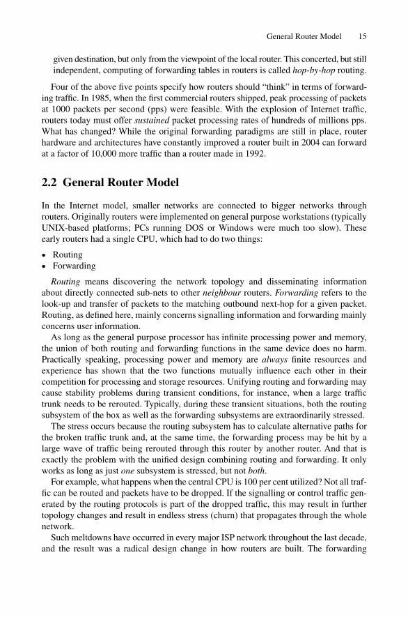
As long as the general purpose processor has infinite processing power and memory,the union of both routing and forwarding functions in the same device does no harm.Practically speaking, processing power and memory are always finite resources andexperience has shown that the two functions mutually influence each other in their competition for processing and storage resources. Unifying routing and forwarding maycause stability problems during transient conditions, for instance, when a large traffictrunk needs to be rerouted. Typically, during these transient situations, both the routingsubsystem of the box as well as the forwarding subsystems are extraordinarily stressed.
The stress occurs because the routing subsystem has to calculate alternative paths forthe broken traffic trunk and, at the same time, the forwarding process may be hit by alarge wave of traffic being rerouted through this router by another router. And that isexactly the problem with the unified design combining routing and forwarding. It onlyworks as long as just one subsystem is stressed, but not both.
For example, what happens when the central CPU is 100 per cent utilized? Not all traf-fic can be routed and packets have to be dropped. If the signalling or control traffic gen-erated by the routing protocols is part of the dropped traffic, this may result in furthertopology changes and result in endless stress (churn) that propagates through the wholenetwork.
Such meltdowns have occurred in every major ISP network throughout the last decade,and the result was a radical design change in how routers are built. The forwarding
General Router Model 15

subsystem was separated from the general purpose platform, and migrated to customhardware that can forward hundreds of millions of packets per second. Customized hard-ware development was necessary as the Internet growth outperformed any PC-basedarchitecture based on, for example, PCI buses.
Figure 2.3 shows essentially how modern routers are structured. The router is parti-tioned into a dedicated control plane and a forwarding plane. The control plane holds thesoftware that the router needs to interact with other routers and human operators. Routerstypically employ a powerful command line interface (CLI), which is used for provision-ing services, configuration management, router troubleshooting and debugging pur-poses. Operator actions are written down in a central configuration file. Changes of theconfiguration file are propagated to the routing processes that “speak” router-to-routerprotocols like OSPF or IS-IS or Border Gateway Protocol (BGP). If the same routingprotocol is provisioned on both ends of a direct router-to-router link, then the routersstart to discover each other in their network. Next, IP routing information is exchanged.The remote network information is entered in the local routing table of the route processor.Next, the forwarding table entries in the control plane and the packet forwarding planehave to be synchronized. Based on this routing table, the forwarding plane starts to program the router hardware, which consists of Application Specific IntegratedCircuits (ASICs) or Field Programmable Gate Arrays (FPGAs), with a subset of the rout-ing table, which is now called the forwarding table. The forwarding table is usually aconcise version of the full routing table containing all IP networks. The forwarding tableonly needs to know routes useful for packet forwarding.
The fowarding plane consists of a number of “input interfaces” (IIF) and a number of“output interfaces” (OIF). The router itself thinks in terms of logical interfaces. Thephysical interface is the actual wire (or fibre) over which the packets flow. In order toactually use a physical interface for forwarding traffic, there needs to be at least one IPaddress assigned to the interface. The IP address combined with a physical interface iscalled a logical interface. There can be more than one logical interface per physical inter-face if the underlying physical media supports channel multiplexing like 801.1Q, Frame
16 2. Router Architecture
Control plane
Forwarding plane
Routingprocess(es) CLI
SNMPprocess
OS kernel
Transit traffic Transit trafficLookup Fabric QueuingIIF OIF
FIGURE 2.3. A blueprint of a modern router showing a clear separation of control plane andforwarding plane

Relay DLCIs or ATM VCs, since each can have an IP address associated with it. If thereis no IP address assigned to a logical interface, then any traffic arriving on that interfacewill be discarded.
Once traffic arrives on the input interface there is typically a lookup engine that triesto determine the next-hop for a given IP address prefix (the prefix is the network portionof the IP address). The next-hop information consists of an outgoing interface plus Layer2 data link framing information. Since the outgoing interface is not enough for multi-access networks like Ethernet LANs, the router needs to prepend the destination MediaAccess Control (MAC) address of the receiver as well.
Next, the packet is transported inside the router chassis by any form of switch fabric.Common switch fabric designs are crossbars, shared memory, shared bus and multistagenetworks. The last stage before final sending of a packet to the next-hop router is thequeuing stage. This buffers packets if the interface is congested, schedules and deliverpackets to an outgoing interface.
2.3 Routing and Forwarding Tables
Just what is the difference between a routing and a forwarding table? The short answer issize and amount of origin information. The routing table of a well-connected Internetcore router today uses dozens of megabytes (MB) of memory to store complete infor-mation about all known Internet routes. Figure 2.4 shows why such a massive amount ofmemory is needed. A router needs to store all the routes that it receives from each neigh-bour. So for each neighbour an Input Routing Information Base (RIB-in) is kept. Due topath redundancy in network cores, a prefix will most likely be known by more than one
Routing and Forwarding Tables 17
RIB-in (1)
Controlplane
Forwardingplane
Transit traffic
Route decisionprocess
Lookup Fabric QueuingIIF OIF
RIB-in (2)
RIB-in (3)
RIB-in (N)
RIB-local
RIB-in (1)
RIB-in (2)
RIB-in (3)
RIB-in (N)CP-FIB
FP-FIB
FIGURE 2.4. Internet core routers need to store what routes have been learned and advertised on aper neighbour basis
path. What the routing software does is to determine the “best” path for a given prefix,sometimes through a complicated tie-breaking process when metrics are the same. Afterthis route selection process the routing software knows the outgoing interface for all ofthe prefixes it has learned from all of its neighbours. This processed table is called theLocal Routing Information Base (RIB-local). The RIB-local table also stores a largeamount of data associated with the prefix, information such as through which protocolwas the route learned, which ISP originated the route information, if the route is subjectto frequent failures (flapping), and so on. Modern routers store about 50–300 bytes ofadditional administrative information for each route, useful for troubleshooting routingproblems, but adding to the resource requirements of the router.
A full-blown Internet routing table from a single upstream contains about 140,000routes consumes about 20–30 MB of memory. This is still a massive amount of memoryif it has to be implemented in an expensive semiconductor technology. For example, theultra fast SRAMs typically used for CPU caches provide faster lookup speeds thanDRAM memory chips, but at great cost, so DRAM is often used for this purpose. Thebenefit of DRAMs is smaller cost per bit of storage compared to SRAM chips. The routerdesigner has to make a call between speed and size to keep the cost competitive and isalways looking for tradeoffs like this.
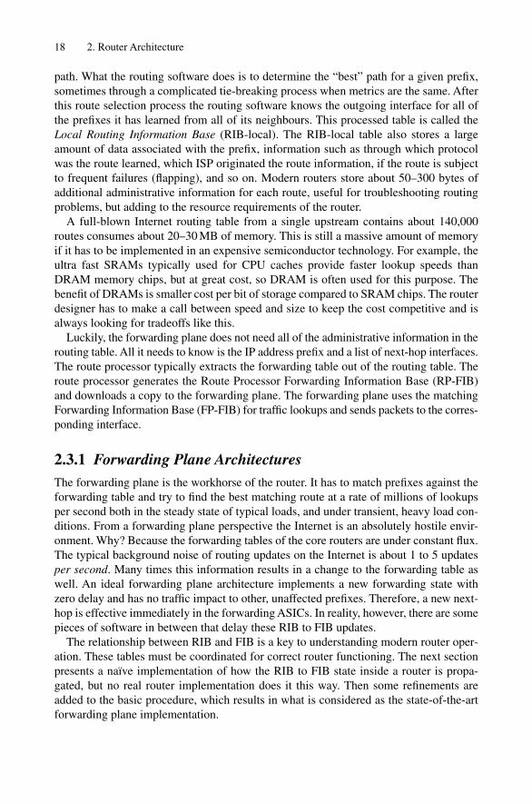
Luckily, the forwarding plane does not need all of the administrative information in therouting table. All it needs to know is the IP address prefix and a list of next-hop interfaces.The route processor typically extracts the forwarding table out of the routing table. Theroute processor generates the Route Processor Forwarding Information Base (RP-FIB)and downloads a copy to the forwarding plane. The forwarding plane uses the matchingForwarding Information Base (FP-FIB) for traffic lookups and sends packets to the corres-ponding interface.
2.3.1 Forwarding Plane ArchitecturesThe forwarding plane is the workhorse of the router. It has to match prefixes against theforwarding table and try to find the best matching route at a rate of millions of lookupsper second both in the steady state of typical loads, and under transient, heavy load con-ditions. From a forwarding plane perspective the Internet is an absolutely hostile envir-onment. Why? Because the forwarding tables of the core routers are under constant flux.The typical background noise of routing updates on the Internet is about 1 to 5 updatesper second. Many times this information results in a change to the forwarding table aswell. An ideal forwarding plane architecture implements a new forwarding state withzero delay and has no traffic impact to other, unaffected prefixes. Therefore, a new next-hop is effective immediately in the forwarding ASICs. In reality, however, there are somepieces of software in between that delay these RIB to FIB updates.
The relationship between RIB and FIB is a key to understanding modern router oper-ation. These tables must be coordinated for correct router functioning. The next sectionpresents a naïve implementation of how the RIB to FIB state inside a router is propa-gated, but no real router implementation does it this way. Then some refinements areadded to the basic procedure, which results in what is considered as the state-of-the-artforwarding plane implementation.
18 2. Router Architecture
2.3.1.1 Naïve Implementation of RIB to FIB Propagation
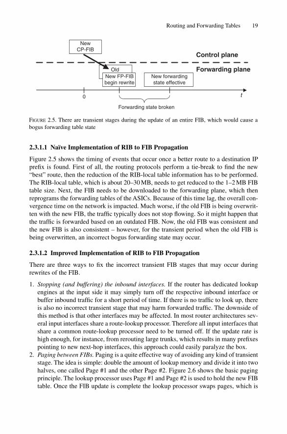
Figure 2.5 shows the timing of events that occur once a better route to a destination IPprefix is found. First of all, the routing protocols perform a tie-break to find the new“best” route, then the reduction of the RIB-local table information has to be performed.The RIB-local table, which is about 20–30 MB, needs to get reduced to the 1–2 MB FIBtable size. Next, the FIB needs to be downloaded to the forwarding plane, which thenreprograms the forwarding tables of the ASICs. Because of this time lag, the overall con-vergence time on the network is impacted. Much worse, if the old FIB is being overwrit-ten with the new FIB, the traffic typically does not stop flowing. So it might happen thatthe traffic is forwarded based on an outdated FIB. Now, the old FIB was consistent andthe new FIB is also consistent – however, for the transient period when the old FIB isbeing overwritten, an incorrect bogus forwarding state may occur.
2.3.1.2 Improved Implementation of RIB to FIB Propagation
There are three ways to fix the incorrect transient FIB stages that may occur duringrewrites of the FIB.
1. Stopping (and buffering) the inbound interfaces. If the router has dedicated lookupengines at the input side it may simply turn off the respective inbound interface orbuffer inbound traffic for a short period of time. If there is no traffic to look up, thereis also no incorrect transient stage that may harm forwarded traffic. The downside ofthis method is that other interfaces may be affected. In most router architectures sev-eral input interfaces share a route-lookup processor. Therefore all input interfaces thatshare a common route-lookup processor need to be turned off. If the update rate ishigh enough, for instance, from rerouting large trunks, which results in many prefixespointing to new next-hop interfaces, this approach could easily paralyze the box.
2. Paging between FIBs. Paging is a quite effective way of avoiding any kind of transientstage. The idea is simple: double the amount of lookup memory and divide it into twohalves, one called Page #1 and the other Page #2. Figure 2.6 shows the basic pagingprinciple. The lookup processor uses Page #1 and Page #2 is used to hold the new FIBtable. Once the FIB update is complete the lookup processor swaps pages, which is
Routing and Forwarding Tables 19
Old
Forwarding state broken
NewCP-FIB
New FP-FIBbegin rewrite
New forwardingstate effective
Control plane
Forwarding plane
t0
FIGURE 2.5. There are transient stages during the update of an entire FIB, which would cause abogus forwarding table state
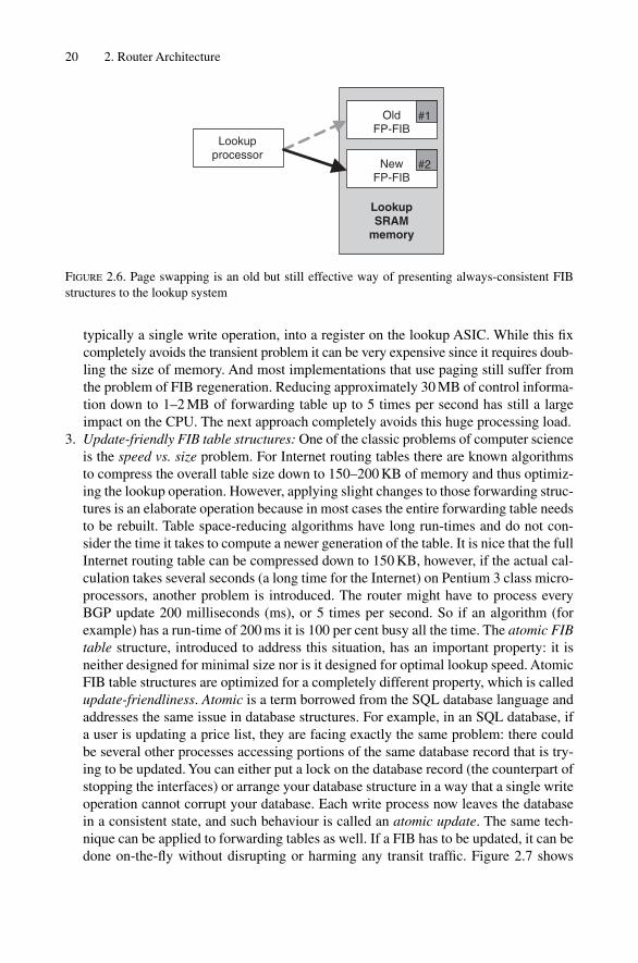
typically a single write operation, into a register on the lookup ASIC. While this fixcompletely avoids the transient problem it can be very expensive since it requires doub-ling the size of memory. And most implementations that use paging still suffer fromthe problem of FIB regeneration. Reducing approximately 30 MB of control informa-tion down to 1–2 MB of forwarding table up to 5 times per second has still a largeimpact on the CPU. The next approach completely avoids this huge processing load.
3. Update-friendly FIB table structures: One of the classic problems of computer scienceis the speed vs. size problem. For Internet routing tables there are known algorithmsto compress the overall table size down to 150–200 KB of memory and thus optimiz-ing the lookup operation. However, applying slight changes to those forwarding struc-tures is an elaborate operation because in most cases the entire forwarding table needsto be rebuilt. Table space-reducing algorithms have long run-times and do not con-sider the time it takes to compute a newer generation of the table. It is nice that the fullInternet routing table can be compressed down to 150 KB, however, if the actual cal-culation takes several seconds (a long time for the Internet) on Pentium 3 class micro-processors, another problem is introduced. The router might have to process everyBGP update 200 milliseconds (ms), or 5 times per second. So if an algorithm (forexample) has a run-time of 200 ms it is 100 per cent busy all the time. The atomic FIBtable structure, introduced to address this situation, has an important property: it isneither designed for minimal size nor is it designed for optimal lookup speed. AtomicFIB table structures are optimized for a completely different property, which is calledupdate-friendliness. Atomic is a term borrowed from the SQL database language andaddresses the same issue in database structures. For example, in an SQL database, ifa user is updating a price list, they are facing exactly the same problem: there couldbe several other processes accessing portions of the same database record that is try-ing to be updated. You can either put a lock on the database record (the counterpart ofstopping the interfaces) or arrange your database structure in a way that a single writeoperation cannot corrupt your database. Each write process now leaves the databasein a consistent state, and such behaviour is called an atomic update. The same tech-nique can be applied to forwarding tables as well. If a FIB has to be updated, it can bedone on-the-fly without disrupting or harming any transit traffic. Figure 2.7 shows
20 2. Router Architecture
OldFP-FIB
Lookupprocessor
NewFP-FIB
LookupSRAM
memory
#1
#2
FIGURE 2.6. Page swapping is an old but still effective way of presenting always-consistent FIBstructures to the lookup system

how an entire branch of new routing information is first stored in the lookup SRAM,and then a new sub-tree is built up. This operation does not harm any transit trafficlookups at all, because the new sub-tree is not yet linked to the old tree. A final writeoperation switches a single pointer between the old sub-tree and the new sub-tree.
Not all of these three approaches are mutually exclusive. In later examples of realrouters, it will be shown that sometimes more than one of these techniques is used inorder to speed up RIB to FIB convergence.
It is clear from this forwarding plane discussion that updating even simple data struc-tures like forwarding tables on-the-fly, particularly on routers that have to carry fullInternet routes, is not an easy task and requires careful system design. Similar diligenceis necessary when writing software for the control plane, or routing engine, and the nextsection considers these architectures.
2.3.2 Control Plane ArchitecturesControl plane software suffers from similar problems first encountered on first-generationrouters implemented on general purpose routing platforms. There are several sub-systemsthat compete for CPU and memory resources. In first-generation routers the forwardingsub-system always hogged CPU cycles. Partitioning the system into a forwarding planeand control plane avoided the packet processing stress placed on the routing protocols.However, a modern control plane has to do more than just run a single instance of a routingprotocol. It usually also has to run a variety of software modules like:
• Several instances of the command line interface (CLI)• Several instances of multiple routing protocols including OSPF, IS-IS and BGP• Several instances of MPLS-related signalling protocols like RSVP and LDP
Routing and Forwarding Tables 21
LookupSRAM
memory
Forwarding plane
(Binary tree data structure)
Old pointer New pointer
Deleted sub-tree New sub-tree
Lookupprocessor
FIGURE 2.7. An atomic update of a routing table sub-tree does not harm any transit traffic

• Several instances of accounting processes, such as the Simple Network ManagementProtocol (SNMP) stack
2.3.2.1 Routing Sub-system Design
Each process that runs on a router operating system (OS) has time-critical events thatneed to be executed in real-time, otherwise the neighbour routers might miss one “Hello”message and declare the router down, causing a ripple effect that destabilizes the entirerouter network. Therefore, all OSs have a scheduler which dispatches CPU cyclesdepending on how timely the process needs to get revisited in order to meet time-criticalevents like sending out IGP Hellos.
Historically the scheduler has been implemented inside the routing protocol module.That design decision has important consequences. First, the routing protocols need to beimplemented in a way that is cooperative to the scheduler. Figure 2.8 shows that routingsoftware and their schedulers work almost like the old Windows 3.11, offering a form ofcooperative multitasking. An application can run as long as it passes control back to thescheduler. In order for the scheduling to work it has to cooperate with the scheduler andtry not to run too long. Often the routing protocols processes need to be sliced and run apiece at a time in order to meet timing constraints.
On busy boxes sometimes the individual sub-processes do not return control in timeback to the scheduler, which causes the following well-known message logs. In the caseof a sub-process not returning control in a timely manner to the scheduler, Cisco Systemsrouters would log a CPU-HOG message like the following:
IOS logging outputAug 7 01:24:07.651: %SYS-3-CPUHOG: Task ran for 7688msec (126/40),
process = ISIS Router, PC = 32804A8.
22 2. Router Architecture
Process A Process BApplicationscheduler
Applicationscheduler
FIGURE 2.8. Per-application scheduling requires that the routing software is written in a cooperative way
A similar message type exists for Juniper Networks routers where the sub-processescannot be revisited in time. The Routing Protocol Daemon (RPD) logs an RPD-SCHEDULER-SLIP message to its local logging facility:
JUNOS logging outputAug 7 03:19:07 rpd[201]: task_monitor_slip: 4s scheduler slip
Special code adjustments need to be taken to avoid CPU-HOGS and scheduler slips. Therouting code constantly needs to sanity check itself to make sure it is not using too manyresources and so harming other sub-processes in the system that may be more critical,like sending OSPF or IS-IS Hellos. In the carrier-class routing code expected by largeISPs, a lot of the code base just deals with timing and avoiding all sorts of what are calledrace conditions, which adds a lot of complexity to the code.
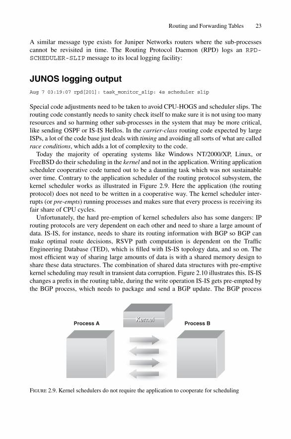
Today the majority of operating systems like Windows NT/2000/XP, Linux, orFreeBSD do their scheduling in the kernel and not in the application. Writing applicationscheduler cooperative code turned out to be a daunting task which was not sustainableover time. Contrary to the application scheduler of the routing protocol subsystem, thekernel scheduler works as illustrated in Figure 2.9. Here the application (the routingprotocol) does not need to be written in a cooperative way. The kernel scheduler inter-rupts (or pre-empts) running processes and makes sure that every process is receiving itsfair share of CPU cycles.
Unfortunately, the hard pre-emption of kernel schedulers also has some dangers: IProuting protocols are very dependent on each other and need to share a large amount ofdata. IS-IS, for instance, needs to share its routing information with BGP so BGP canmake optimal route decisions, RSVP path computation is dependent on the TrafficEngineering Database (TED), which is filled with IS-IS topology data, and so on. Themost efficient way of sharing large amounts of data is with a shared memory design toshare these data structures. The combination of shared data structures with pre-emptivekernel scheduling may result in transient data corruption. Figure 2.10 illustrates this. IS-ISchanges a prefix in the routing table, during the write operation IS-IS gets pre-empted bythe BGP process, which needs to package and send a BGP update. The BGP process
Routing and Forwarding Tables 23
BProcess A Process B
KernelKernel
FIGURE 2.9. Kernel schedulers do not require the application to cooperate for scheduling
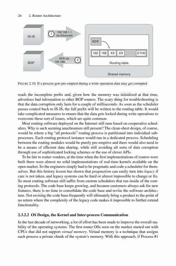
reads the incomplete prefix and, given how the memory was initialized at that time,advertises bad information to other BGP routers. The scary thing for troubleshooting isthat the data corruption only lasts for a couple of milliseconds. As soon as the schedulerpasses control back to IS-IS, the full prefix will be written to the routing table. It wouldtake complicated measures to ensure that the data gets locked during write operations toovercome these sort of issues, which are quite common.
Most routing software deployed on the Internet still runs based on cooperative sched-ulers. Why is such seeming anachronism still present? The clean-sheet design, of course,would be where a big “all protocols” routing process is partitioned into individual sub-processes. Each routing protocol instance would run in a dedicated process. Schedulingbetween the routing modules would be purely pre-emptive and there would also need tobe a means of efficient data sharing, while still avoiding all sorts of data corruptionthrough use of sophisticated locking schemes or the use of clever APIs.
To be fair to router vendors, at the time when the first implementations of routers werebuilt there were almost no solid implementations of real-time kernels available on theopen market. So the engineers simply had to be pragmatic and code a scheduler for them-selves. But this history lesson has shown that pragmatism can easily turn into legacy ifcare is not taken, and legacy systems can be hard or almost impossible to change or fix.So most routing software still suffer from custom schedulers that run inside of the rout-ing protocols. The code base keeps growing, and because customers always ask for newfeatures, there is no time to consolidate the code base and revise the software architec-ture. Not revising the code base frequently will ultimately bring a product to the point ofno return where the complexity of the legacy code makes it impossible to further extendfunctionality.
2.3.2.2 OS Design, the Kernel and Inter-process Communication
In the last decade of networking, a lot of effort has been made to improve the overall sta-bility of the operating systems. The first router OSs seen on the market started out withCPUs that did not support virtual memory. Virtual memory is a technique that assignseach process a private chunk of the system’s memory. With this approach, if Process #1
24 2. Router Architecture
Shared memory
Routing table
192.168.1.1via Ethernet0
192
IS-IS
BGP62/8 via
192.168.XX.XX
ETH0
1
2
168 XX XX
62/8
FIGURE 2.10. If a process gets pre-empted during a write operation data may get corrupted

tries to access Process #2’s memory, then Process #1 is immediately terminated. Whythen is virtual memory today imperative? Virtual memory greatly enhances the overallsystem stability by limiting local damage.
No matter how much time and resources put into testing efforts, there will be alwayssome bugs that are only unveiled in a production environment. So there is some residualrisk that certain processes will crash. What virtual memory helps is to mitigate theimpact that a crashed piece of software has to the overall system. In early router OSs, forexample, a tiny bug in relatively unimportant parts of the system, like the CLI, couldoverwrite another process’s BGP neighbor tables. The result would be incorrect adver-tisements and incorrect processing of incoming data that might cause not only the entirerouter to crash, but also affect other routers as incorrect information is propagated in turnand ripples through the network to crash other routers.
Modern control plane software typically consists of 1–2 millions line of code, whichleaves plenty of room for lots of bugs. A software design technique called graceful degra-dation is becoming more important for distributed systems like router networks. The basicidea is that a big piece of software is broken down in small atomic modules. – To provideisolation each module gets its own process and virtual-memory. However, sometimesprocesses need to share data being held by another process. For example, listing a neigh-boring router’s route advertisements requires the CLI to ask the BGP process what routesit received from neighbors. All the processes need to use a common exchange mechanismlike a message-passing API in order to interact with each other. The message-passing APIis one of the things that each modern kernel offers to its processes. The kernel itself is theroot of the operating system. It starts and stops processes and passes messages alongbetween processes.
Figure 2.11 shows an example of a message-passing atomic-module system. The ker-nel offers a generalized, uniform messaging system for interaction and thereby providesunmatched stability. Do not be misled: the kernel does not stop individual processes fromcrashing. But it does help limit the impact of the crashed piece of software on otherprocesses in the same system. After a process dies, the kernels watchdog waits a coupleof seconds and restarts the broken software again. It is common practice to write a logentry into the system’s log that a process has been crashed and restarted, ultimately alert-ing the Network Operation Center (NOC) to the problem.
The advantage is clear: a single network incident like, for example, a bug in IGPAdjacency Managements crashes only one Adjacency and does not take out the entirerouter for 2–3 minutes to complete a reboot.
No of the two Vendors implementation discussed in this book encompasses the idea ofatomic modules communicating through the kernel. The main argument of the propo-nents of monolithic software is that the amount of data sharing that is required for exam-ple in the routing subsystem will overload the inter-process communication system ofthe kernel. The traditional vehicle is to share memory between modules inside a process.The disadvantage here is full fate-sharing: If there is a single software problem in theprocess the entire process will crash and render the router control-plane unusable forminutes.
However it remains to be seen if the atomic modules and massive inter-process commu-nication model can perform at a similar performance level than today’s shared-memory
Routing and Forwarding Tables 25

model. If atomic-modules get close to par they are the next logical step to evolve routercontrol plane software.
In summary, proper partitioning of the control plane software helps prevent local bugsfrom spreading to a system-wide crisis. Virtual memory shields the processes and theirassociated memory from each other. In order to exchange information betweenprocesses, the kernel offers a message-passing API. Once again, scaling by partitioninghas helped to solve the problem of OS instability.
2.4 Router Technology Examples
Building routers is a complicated and daunting task. There are probably only a few dozenpeople in the industry that really know how to architect and design a modern router,because of the inherent complexity. A lot of the insight on how to build routers that scalewas gathered by actually deploying premature implementations of software and usingthe feedback that the deployment experience provided into the design of next-generationrouters. In the next few sections, popular router models and their design concepts will beoutlined.
26 2. Router Architecture
IS-ISAdj-Mnt
Instance 0
IS-ISSPF-run
Instance 0
BGPresolver
Instance 0
BGPsess-mgrInstance 0
Kernel (message-passing)
OSPFAdj-MntInstanceVRF-blue
OSPFSPF-runInstanceVRF-blue
Kernel
Shared Memory CLI SNMP
IS-IS
LDP BGP
OSPF
FIGURE 2.11. Modern OSs offer a message-passing API for processes to communicate to each other

2.4.1 Cisco 7500 SeriesThe Cisco 7500 series of router was the most successful router ever built for Internet coreapplications. Figure 2.12 shows the overall structure of the box. Basically, it is a redun-dant shared bus system with one element dual-homed to both buses. The shared buseshave different speeds, depending on the revision level. Bus speeds range from the CxBus(533 Mbit/s half-duplex) to the CyBus (1.2 Gbit/s half-duplex) and finally the CzBus(2.5 Gbit/s half-duplex).
The Route Switch Processor (RSP) has to run both the routing software and also needsto switch packets. The first-generation interface cards are called Interface Processors andare from Network-Layer viewpoint purely passive devices. The IPs perform Layer-1(Physical Layer) and Layer-2 (MAC Layer) related tasks like verifying CRC checksums,SONET messaging or ATM SAR functions. If a packet enters the box, an interrupt is sig-nalled to the RSP. The RSP fetches the packet and does a route-lookup to find the corre-sponding outbound interface. All relevant modifications to the IP header, such as TTLdecrementing and recalculating the IP header’s checksum, are done by the RSP. Then thepacket is copied to the outgoing interface where it ultimately leaves the chassis.
The RSP forwarding module needs to have efficient route-lookup structures in orderto spend minimum lookup times before making forwarding decisions. The forwardinginformation base (FIB) is known to Cisco Systems as the Cisco Express Forwarding(CEF) Table. In Figure 2.13 there are two examples of how the lookup for IP address4.6.2.1 traverses the CEF Table. The basic structure is a 256-way 4-level structure calledan M-tree. The four levels are located at the /8, /16, /24 and /32 prefix boundaries. Each
Router Technology Examples 27
• • •
Routeswitch
processor
Passive (IP)line card
Passive (IP)line card
Passive (IP)line card
1
2
FIGURE 2.12. The first generation Interface Processor (IP) Cards did not embed route-lookup func-tionality. All the traffic has been passed via the Route Switch Processor (RSP).
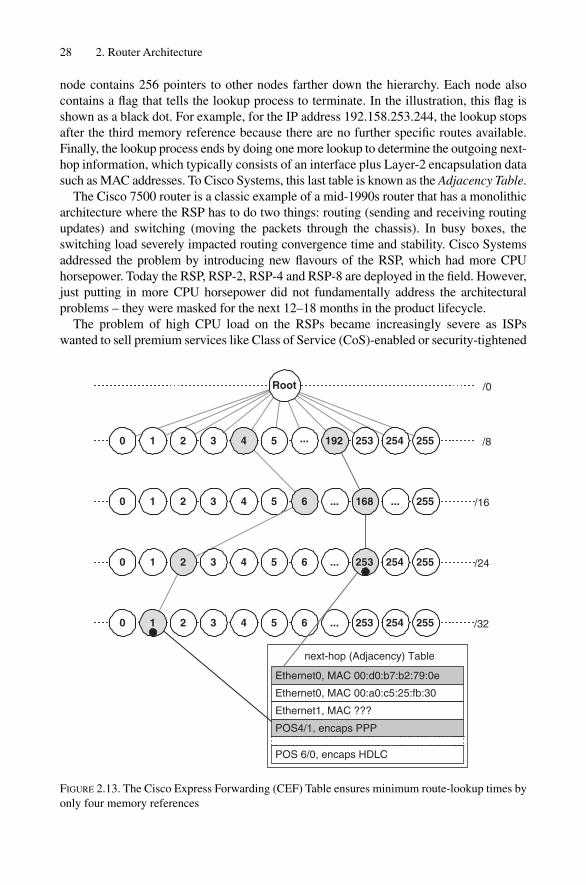
node contains 256 pointers to other nodes farther down the hierarchy. Each node alsocontains a flag that tells the lookup process to terminate. In the illustration, this flag isshown as a black dot. For example, for the IP address 192.158.253.244, the lookup stopsafter the third memory reference because there are no further specific routes available.Finally, the lookup process ends by doing one more lookup to determine the outgoing next-hop information, which typically consists of an interface plus Layer-2 encapsulation datasuch as MAC addresses. To Cisco Systems, this last table is known as the Adjacency Table.
The Cisco 7500 router is a classic example of a mid-1990s router that has a monolithicarchitecture where the RSP has to do two things: routing (sending and receiving routingupdates) and switching (moving the packets through the chassis). In busy boxes, theswitching load severely impacted routing convergence time and stability. Cisco Systemsaddressed the problem by introducing new flavours of the RSP, which had more CPUhorsepower. Today the RSP, RSP-2, RSP-4 and RSP-8 are deployed in the field. However,just putting in more CPU horsepower did not fundamentally address the architecturalproblems – they were masked for the next 12–18 months in the product lifecycle.
The problem of high CPU load on the RSPs became increasingly severe as ISPswanted to sell premium services like Class of Service (CoS)-enabled or security-tightened
28 2. Router Architecture
next-hop (Adjacency) Table
POS 6/0, encaps HDLC
/80 1 2 3 5 ... 253 254 255
/160 1 2 3 4 5 ... 255...
/240 1 4 5 6 254 255...
/320 2 3 4 5 6 254 255
2
... 253
4
3
6
Ethernet0, MAC 00:d0:b7:b2:79:0e
Ethernet0, MAC 00:a0:c5:25:fb:30
Ethernet1, MAC ???
POS4/1, encaps PPP
/0Root
1
192
168
253
FIGURE 2.13. The Cisco Express Forwarding (CEF) Table ensures minimum route-lookup times byonly four memory references

networks. Doing additional classification and firewalling work besides the plain-vanilladestination IP address route lookups resulted in decreased forwarding performance, insome cases down to several 10K pps. The 7500 architecture had to be extended to offloadmuch of the switching decisions down to the interface level. With the next generation ofInterface Ports, the Versatile Interface Processor (VIP) was born.
2.4.2 Cisco 7500 Series � VIP ProcessorsThe VIP concept is an improvement to the passive line card architecture of the plain 7500series. The slots of the routers are populated with VIP cards, which are essentially carriercards that hold Port Adapters (PAs). The PAs perform similar low-level functions to theolder IP line cards. The VIP adapter itself runs a custom, stripped down version of IOSthat harbours mostly switching and classification functions in order to offload the RSPfrom switching the packets. The VIP architecture was a real step forward in improvingswitching performance and bus utilization. Using the old-style IP line cards, the bus wasused twice, as shown in Figure 2.12: once for the IP to RSP transfer, and then for the RSPto IP transfer. Figure 2.14 shows that if the packet is transferred direct from one VIP toanother, the bus is traversed only a single time.
The distributed VIP architecture revealed an interesting issue: how to replicate the FIBtable to several line cards? As the route lookup was done in a distributed fashion, a pieceof software needed to make sure that the local FIB gets replicated to all the VIP adaptersin the system. Distributed CEF (dCEF) was developed to provide the proper care andfeeding of VIP line cards. But deployment of dCEF in the field revealed a weakness inthe way that FIB tables are built: the VIP card is a pure switching entity, and as such it
Router Technology Examples 29
• • •
RouteRouteswitch
processor
Active (VIP)line card
Active (VIP)line card
Active (VIP)line card
1
FIGURE 2.14. The Versatile Interface Processor transfers VIP to VIP traffic without Route SwitchProcessor intervention

also needs a piece of software that calculates the FIB based on the RIB. During transientconditions when, for example, a large part of Internet traffic is rerouted, FIB computationturns out to be a fairly expensive task. The VIP card does local switching and the RSPperforms control plane functionality, plus building the FIBs on behalf of the VIPadapters. And that is exactly the weak point of the architecture, because the RSP stillneeds to do too much work that would be done better at the VIP card level. There is notrue decoupling of forwarding and control functions here. For better stability, it probablywould have been a better design choice to replicate the local RIB to the VIP cards and letthem do the FIB generation.
Around the same time, it became apparent that the enormous growth of the Internetwas outpacing advances in bus speeds. So the 7500s, which had once been the corerouters, moved to the edge and began performing customer traffic and route aggregationfunctions. The concept of the shared bus had to be replaced by a true fabric enabling linecard speeds beyond OC-12/STM-4 speeds of 622 Mbps, which is still the architecturallimit of the 7500 � VIP series. It was clear that changing the heart of the router, whichis the fabric, leads to a change of the line-cards, the VIPs and the PAs. Essentially awhole new router needed to be designed.
2.4.3 Cisco GSR SeriesThe Cisco 12000 Series, sometimes referred to as the Gigabit Switch Router (GSR), is basi-cally a meshof high-speed VIPs that perform independent, local route and classificationlookups. Figure 2.15 illustrates the concept in brief. The glue that holds these line cardstogether is a single-stage crossbar that provides up to 80 Gbit/s I/O bandwidth. The succes-sor of the 12000 Series is the 12400, which offers an increased crossbar bandwidth of320 Gbit/s. The route processor and the crossbar fabric are designed redundant. If one com-ponent breaks the other will take over. There are four different types of line cards for theGSR Series, starting with Engine-0 line cards, which offer only software processing like theVIP processors on the 7500 series. There are also Engine-2 line cards using custom ASIChardware and Engine-3 cards are the second generation of ASIC hardware. Finally, Engine-4 line cards are targeted for the new high-speed fabric of the Cisco 12400 Series intended to
30 2. Router Architecture
• • •
Routeprocessor
Activeline card
Activeline card
• • •
Crossbarfabric
Routeprocessor
Activeline card
Activeline card
FIGURE 2.15. The GSR 12000 Series concept is a crossbar fabric surrounded by active line cards
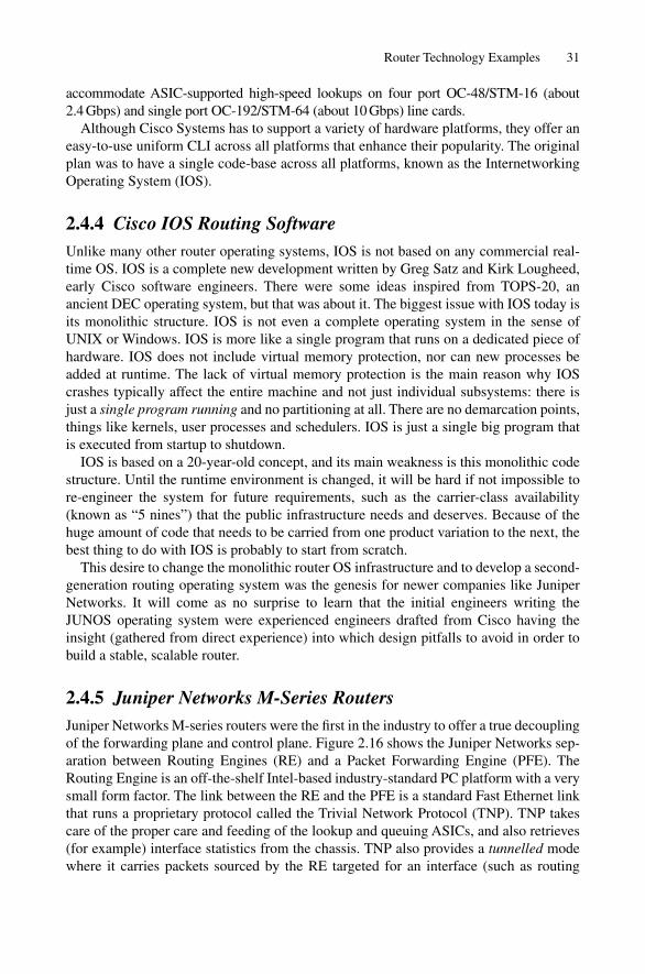
accommodate ASIC-supported high-speed lookups on four port OC-48/STM-16 (about2.4 Gbps) and single port OC-192/STM-64 (about 10 Gbps) line cards.
Although Cisco Systems has to support a variety of hardware platforms, they offer aneasy-to-use uniform CLI across all platforms that enhance their popularity. The originalplan was to have a single code-base across all platforms, known as the InternetworkingOperating System (IOS).
2.4.4 Cisco IOS Routing SoftwareUnlike many other router operating systems, IOS is not based on any commercial real-time OS. IOS is a complete new development written by Greg Satz and Kirk Lougheed,early Cisco software engineers. There were some ideas inspired from TOPS-20, anancient DEC operating system, but that was about it. The biggest issue with IOS today isits monolithic structure. IOS is not even a complete operating system in the sense ofUNIX or Windows. IOS is more like a single program that runs on a dedicated piece ofhardware. IOS does not include virtual memory protection, nor can new processes beadded at runtime. The lack of virtual memory protection is the main reason why IOScrashes typically affect the entire machine and not just individual subsystems: there isjust a single program running and no partitioning at all. There are no demarcation points,things like kernels, user processes and schedulers. IOS is just a single big program thatis executed from startup to shutdown.
IOS is based on a 20-year-old concept, and its main weakness is this monolithic codestructure. Until the runtime environment is changed, it will be hard if not impossible tore-engineer the system for future requirements, such as the carrier-class availability(known as “5 nines”) that the public infrastructure needs and deserves. Because of thehuge amount of code that needs to be carried from one product variation to the next, thebest thing to do with IOS is probably to start from scratch.
This desire to change the monolithic router OS infrastructure and to develop a second-generation routing operating system was the genesis for newer companies like JuniperNetworks. It will come as no surprise to learn that the initial engineers writing theJUNOS operating system were experienced engineers drafted from Cisco having theinsight (gathered from direct experience) into which design pitfalls to avoid in order tobuild a stable, scalable router.
2.4.5 Juniper Networks M-Series RoutersJuniper Networks M-series routers were the first in the industry to offer a true decouplingof the forwarding plane and control plane. Figure 2.16 shows the Juniper Networks sep-aration between Routing Engines (RE) and a Packet Forwarding Engine (PFE). TheRouting Engine is an off-the-shelf Intel-based industry-standard PC platform with a verysmall form factor. The link between the RE and the PFE is a standard Fast Ethernet linkthat runs a proprietary protocol called the Trivial Network Protocol (TNP). TNP takescare of the proper care and feeding of the lookup and queuing ASICs, and also retrieves(for example) interface statistics from the chassis. TNP also provides a tunnelled modewhere it carries packets sourced by the RE targeted for an interface (such as routing
Router Technology Examples 31
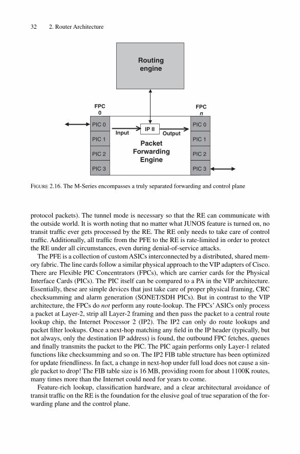
protocol packets). The tunnel mode is necessary so that the RE can communicate withthe outside world. It is worth noting that no matter what JUNOS feature is turned on, notransit traffic ever gets processed by the RE. The RE only needs to take care of controltraffic. Additionally, all traffic from the PFE to the RE is rate-limited in order to protectthe RE under all circumstances, even during denial-of-service attacks.
The PFE is a collection of custom ASICs interconnected by a distributed, shared mem-ory fabric. The line cards follow a similar physical approach to the VIP adapters of Cisco.There are Flexible PIC Concentrators (FPCs), which are carrier cards for the PhysicalInterface Cards (PICs). The PIC itself can be compared to a PA in the VIP architecture.Essentially, these are simple devices that just take care of proper physical framing, CRCchecksumming and alarm generation (SONET/SDH PICs). But in contrast to the VIParchitecture, the FPCs do not perform any route-lookup. The FPCs’ASICs only processa packet at Layer-2, strip all Layer-2 framing and then pass the packet to a central routelookup chip, the Internet Processor 2 (IP2). The IP2 can only do route lookups andpacket filter lookups. Once a next-hop matching any field in the IP header (typically, butnot always, only the destination IP address) is found, the outbound FPC fetches, queuesand finally transmits the packet to the PIC. The PIC again performs only Layer-1 relatedfunctions like checksumming and so on. The IP2 FIB table structure has been optimizedfor update friendliness. In fact, a change in next-hop under full load does not cause a sin-gle packet to drop! The FIB table size is 16 MB, providing room for about 1100K routes,many times more than the Internet could need for years to come.
Feature-rich lookup, classification hardware, and a clear architectural avoidance oftransit traffic on the RE is the foundation for the elusive goal of true separation of the for-warding plane and the control plane.
32 2. Router Architecture
Routingengine
FPC0
FPCn
IP IIInput Output
PacketForwarding
Engine
PIC 0
PIC 1
PIC 2
PIC 3
PIC 0
PIC 1
PIC 2
PIC 3
FIGURE 2.16. The M-Series encompasses a truly separated forwarding and control plane

2.4.6 JUNOS Routing SoftwareThe JUNOS operating system is built around a FreeBSD 4.2-STABLE UNIX operatingsystem. The kernel is different to the usual FreeBSD kernel. Special care has been takento ensure scalability and the kernel is modified to support multiple routing tables, mil-lions of routes and thousands of interfaces. Because UNIX offers full virtual memoryprotection, the system is split up in many different user processes, as illustrated in Figure2.17. The routing code is still bundled in a single process for all the routing protocolsacross all routing instances, so the issue of scheduling is still present. If a large wave ofBGP updates hits the system, it is possible to miss sending IGP Hellos. But the UNIX-based package also provides a way around this issue. There is a dedicated daemon(server process) in JUNOS called the Periodic Packet Management Daemon (PPMD).The IGPs register with PPMD, which sends out the IGP Hellos on their behalf. PPMDcompletely offloads Hello processing from the RPD, and the RPD does not need to han-dle periodic Hellos at all. The RPD is notified by PPMD if an important event like anadjacency expiration occurs. PPMD runs with the highest scheduling priority in the systemand may pre-empt any process to make sure that every IGP Hello is delivered in time.
In summary, JUNOS is a true example of a second-generation router operatingSystem. Many lessons learned from deployment experience with Cisco IOS have beenincorporated into the software. The software is modular in order to overcome the fate-sharing problems in monolithic designs. At the time of writing, the number of activeprocesses in a functioning router was 37, an extraordinary number. Partitioning the codecarefully ensures that each single subsystem becomes maintainable and protects theoverall system from avalanche effects caused by local bugs.
2.5 Conclusion
The evolution of the Internet is so fast that it is difficult for core routers to keep up. Both forwarding user traffic and processing control traffic in a network that doubles inspeed and size every nine months is a daunting task. To tackle the problem of scaling,
Conclusion 33
KernelKernel
rpdrpd mgdmgd chassidchassid ….. ppmdppmd
Real-timecode pieces
FIGURE 2.17. JUNOS software is partitioned across many user level processes

one common technique is repeatedly used: partitioning. The first occurrence of parti-tioning is the Internet routing paradigm itself. Hosts need to perform more dissimilarfunctions than routers have to do. Partitioning is the tool of choice to scale router scala-bility problems. In modern routers, the control plane has been separated from theforwarding plane. This separation does not rely on shared resources like CPU cycles andmemory. Next, clever ways of manipulating forwarding table structures while forward-ing traffic at full speed have been developed. Partitioning the route lookup and tablemaintenance functions addressed the challenges of an ever-and-yet-never-quite converg-ing Internet. Finally, control plane software has been partitioned twice. First, the interac-tion and memory protection of routing software inside the system is secured via a kernelthat each process relies upon, greatly minimizing the impact of broken software. Second,the routing protocols are split up into a real-time component and a non-real-time com-ponent, further improving convergence time granularity as well as removing a lot ofcomplexity from the routing code.
All in all, partitioning is the prevailing scaling method that helps to scale the Internetand its building block, the router.
34 2. Router Architecture

3
Introduction to the IOS and JUNOSCommand Line Interface
35
In the router world, ISPs and carriers got used to the fact that routers are configured andmanaged using an ASCII-based command line interface. Even if this seems scary the firsttime, especially when used to fancy graphical user interfaces (GUI), command line inter-faces give unmatched control over the router and provide a powerful troubleshootingtool.
The Internet is a network that is constantly under flux – somebody somewhere is alwayschanging something. Moreover, new protocol standards evolve, new releases of routingsoftware are deployed, peering policy may change as a result of business constraints oracquisitions, and so on. All this makes for a challenging environment that, at least not upto now, could be modelled in the form of a GUI. In this chapter we will give a basicoverview of how to interact with this kind of interface. You will learn in this chapter how to upload a new configuration, how to query IS-IS related status and finally how totroubleshoot and debug adjacency formation and link-state databases.
3.1 Common Properties of Command Line Interfaces (CLI)
When Cisco Systems shipped it first product called “ISH” back in 1986, no one imaginedthat the company would be redefining how operators interacted with routers for the nexttwo decades. At first sight a command line interface might look primitive; however, thereare important aspects and elements that helped the company achieve its breathtakingsuccess. There are many theories about why Cisco Systems got to where they are in theindustry today. From a technical viewpoint, two key properties helped people feel com-fortable with the Cisco router’s interface. The first is that after changing the router’s con-figuration, everything was written into a single file that is kept in the Non-Volatile RAM(NVRAM) of the router. Virtually everything that the router does, for example runningrouting protocols, performing access control, or using static routes, is controlled by thissingle file. The second important aspect is that the router’s configuration file was anASCII file and is therefore human-readable. Unlike other router companies who storedtheir configuration file in binary form, the IOS configuration files could be read out onthe fly and everybody understood exactly what the router was supposed to do.
There are two other main advantages of single ASCII configuration files. First, supportgets easier. It is a matter of fact that a large fraction of support calls are configurationrelated. An ASCII configuration file enabled operators to simply copy and paste their
router configuration into an email when requesting support. The Technical AssistanceCentre (TAC) could then very quickly see if this was a configuration issue or if the soft-ware had a bug and further analysis of the problem was required. There are even those inthe industry who argue that ASCII-based configuration files make the support organiza-tion scale more effectively and work most efficiently.
The second main advantage is that customers did not need to have a live router to gen-erate configuration files. If the router’s configuration was stored in binary form, there isno opportunity for a third-party application or a “quick-hack” script to generate a validconfiguration file. Router configurations that could be generated by standard UNIX toolslike SED, AWK and PERL were a first-generation way of eventually making a provi-sioning API available for configuration robot tools.
Perhaps Proteon (an ancient router vendor from the 1980s) had an interface that pro-vides the best example of how not to do router configuration:
• Configuration was purely done using menus that never showed you where you werein the configuration statement hierarchy.
• Configuration and show commands had a totally different look and feel (for those whoare familiar with this, just recall the jumping between T5 and T6 command shells).
• Everything was stored in a binary file.• There was no possibility to employ external provisioning tools.
Cisco overtook Proteon in the market at the end of 1980s for various reasons. But onereason was definitely the odd command line interface of Proteon routers. Not that a soundCLI automatically paves the way for success in the router industry, but it clearly does help.
The two ASCII-based command line interfaces of IOS and JUNOS are similar to eachother in some respects, and different in others. The following sections highlight thesecommon elements. Then the differences between IOS and JUNOS (and also the intendedimprovements JUNOS made to IOS) will be discussed as well.
Routers are typically accessed in three ways:
• RS232 serial console• In-band access via telnet or Secure Shell (SSH)• Out-of-band access via telnet or SSH.
Once you have logged on the router, there are two general modes of talking to the router.The first one is called the operational mode. This mode is mainly used to explore what therouter and its environment are doing, what routes are being installed in the system and ifinterfaces are carrying traffic. The other mode is the configuration mode. In the configura-tion mode the router’s behaviour is controlled, for example, what IP address does it have,what routing protocols parameters are used, who can access the router or network, and so on.
3.1.1 Operational ModeOnce you log into a router you usually find yourself in operational mode. The trailing“�” sign indicates that you are working in operational mode. In JUNOS the promptlooks like this:
hannes@New-York>
36 3. Introduction to the IOS and JUNOS Command Line Interface
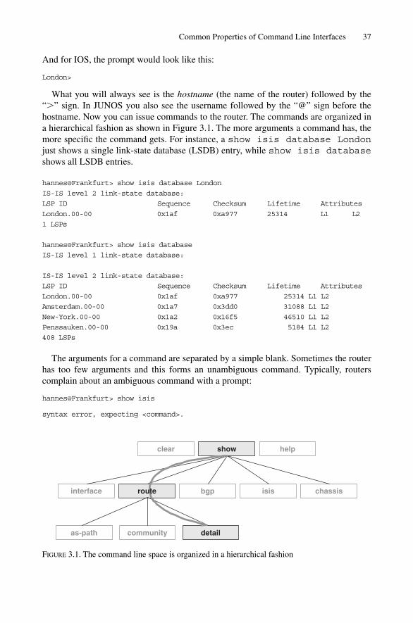
And for IOS, the prompt would look like this:
London>
What you will always see is the hostname (the name of the router) followed by the“�” sign. In JUNOS you also see the username followed by the “@” sign before thehostname. Now you can issue commands to the router. The commands are organized ina hierarchical fashion as shown in Figure 3.1. The more arguments a command has, themore specific the command gets. For instance, a show isis database Londonjust shows a single link-state database (LSDB) entry, while show isis databaseshows all LSDB entries.
hannes@Frankfurt> show isis database London
IS-IS level 2 link-state database:
LSP ID Sequence Checksum Lifetime Attributes
London.00-00 0x1af 0xa977 25314 L1 L2
1 LSPs
hannes@Frankfurt> show isis database
IS-IS level 1 link-state database:
IS-IS level 2 link-state database:
LSP ID Sequence Checksum Lifetime Attributes
London.00-00 0x1af 0xa977 25314 L1 L2
Amsterdam.00-00 0x1a7 0x3dd0 31088 L1 L2
New-York.00-00 0x1a2 0x16f5 46510 L1 L2
Penssauken.00-00 0x19a 0x3ec 5184 L1 L2
408 LSPs
The arguments for a command are separated by a simple blank. Sometimes the routerhas too few arguments and this forms an unambiguous command. Typically, routerscomplain about an ambiguous command with a prompt:
hannes@Frankfurt> show isis
syntax error, expecting <command>.
Common Properties of Command Line Interfaces 37
show
bgp isis chassisinterface
community detailas-path
clear help
route
FIGURE 3.1. The command line space is organized in a hierarchical fashion

This is from a router running JUNOS and
Munich>show isis
% Incomplete command.
is from an IOS-based router. However, there is an easy way to discover what kinds ofcommands the router gives you: context-sensitive help.
3.1.1.1 Context-sensitive Help
At any time, you can enter a question mark (?) at the user prompt, which makes the CLIdisplay all the options that are available at this point in the command-line hierarchy:
hannes@Frankfurt> show isis ?
Possible completions:
adjacency Show the IS-IS adjacency database
database Show the IS-IS link-state database
hostname Show IS-IS hostname database
interface Show IS-IS interface information
route Show the IS-IS routing table
spf Show information about IS-IS SPF calculations
statistics Show IS-IS performance statistics
You will see the keywords that are available, plus a brief descriptive text about whatkind of information is displayed by the respective option.
If the question mark is keyed in the middle of an argument, the CLI shows you whatvalid completions are still left. Note above that there are two keywords after show isisstarting with the letter “S”. The keywords “spf” and “statistics” both start with the sameletter. What you can do is issue a show isis s command and then type the question mark:
hannes@Frankfurt> show isis s?
Possible completions:
spf Show information about IS-IS SPF calculations
statistics Show IS-IS performance statistics
The router shows you the two possible completions. If there are no valid completionsthen the router simply responds with:
hannes@Frankfurt > show isis j?
No valid completions
Sometimes the keywords available in the CLI can be very long and the command lineinterfaces often offer shortcuts to the keywords. That is, it is not really a shortcut, it ismore that the command line parser looks to see if your input is unambiguous and thenaccepts the keyword. So the commands do not have to be specified to the full extent:
London> sh is d
produces the same output as:
London> show isis database
38 3. Introduction to the IOS and JUNOS Command Line Interface

3.1.1.2 Auto-complete
Sometimes these shortcuts are also known as auto-complete functionality. It is not quitethe same thing, however. What auto-complete means is that you can press the �TAB� keyevery time you want to check if you have supplied enough characters for a keyword sothe command is unambiguous. For example, if you enter:
London> show i<TAB>
then you get:
London> show i
In other words, nothing happens if the letters supplied are ambiguous. However, if yousupply enough letters like:
London> show is<TAB>
then you get:
London> show isis
Auto-complete proved to be a powerful tool for experienced users quickly needingoutput, for instance, when troubleshooting a network problem.
The second major mode of router CLI operation is the configuration mode that con-trols the router’s behaviour.
3.1.2 Configuration ModeYou can switch from the operational mode to the configuration mode by issuing commandslike configure or configure terminal. On JUNOS routers you see that you arenow in configuration mode because the prompt has been changed from “�” to “#”
hannes@New-York> configure
Entering configuration mode
[edit]
hannes@New-York#
You also can see that you are in the configuration mode because each time you pressthe �ENTER� key your prompt is prepended by [EDIT], which always indicates thatyou are in the configuration mode.
On IOS platforms you cannot get directly to configuration mode. You first get intowhat is called the privileged enable mode.
London>enable
Password: *******
London#conf terminal
Enter configuration commands, one per line. End with CNTL/Z.
London(config)#
Just as in JUNOS there is the # indication in the prompt that tells you that you are inconfiguration mode. You also see the config keyword in parentheses after the router’shostname and the prompt.
Common Properties of Command Line Interfaces 39
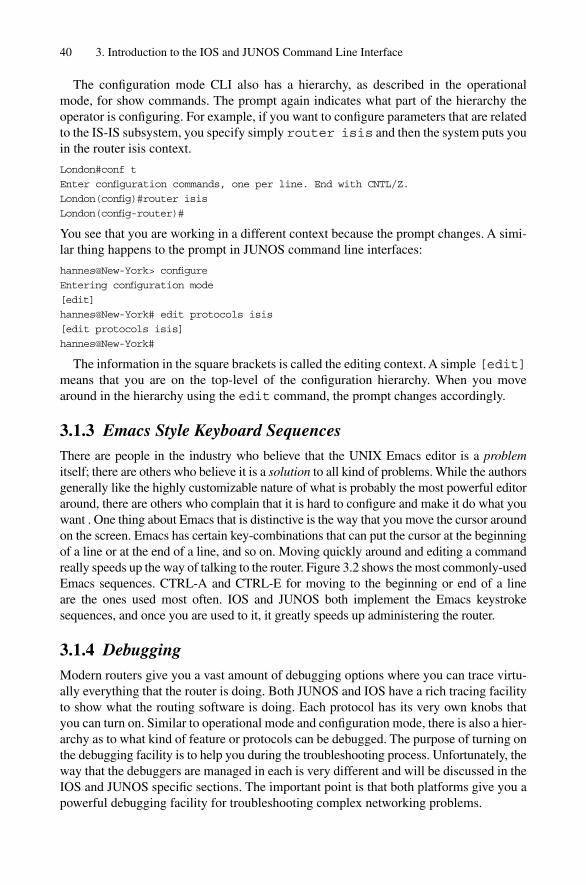
The configuration mode CLI also has a hierarchy, as described in the operationalmode, for show commands. The prompt again indicates what part of the hierarchy theoperator is configuring. For example, if you want to configure parameters that are relatedto the IS-IS subsystem, you specify simply router isis and then the system puts youin the router isis context.
London#conf t
Enter configuration commands, one per line. End with CNTL/Z.
London(config)#router isis
London(config-router)#
You see that you are working in a different context because the prompt changes. A simi-lar thing happens to the prompt in JUNOS command line interfaces:
hannes@New-York> configure
Entering configuration mode
[edit]
hannes@New-York# edit protocols isis
[edit protocols isis]
hannes@New-York#
The information in the square brackets is called the editing context. A simple [edit]means that you are on the top-level of the configuration hierarchy. When you movearound in the hierarchy using the edit command, the prompt changes accordingly.
3.1.3 Emacs Style Keyboard SequencesThere are people in the industry who believe that the UNIX Emacs editor is a problemitself; there are others who believe it is a solution to all kind of problems. While the authorsgenerally like the highly customizable nature of what is probably the most powerful editoraround, there are others who complain that it is hard to configure and make it do what youwant . One thing about Emacs that is distinctive is the way that you move the cursor aroundon the screen. Emacs has certain key-combinations that can put the cursor at the beginningof a line or at the end of a line, and so on. Moving quickly around and editing a commandreally speeds up the way of talking to the router. Figure 3.2 shows the most commonly-usedEmacs sequences. CTRL-A and CTRL-E for moving to the beginning or end of a line are the ones used most often. IOS and JUNOS both implement the Emacs keystrokesequences, and once you are used to it, it greatly speeds up administering the router.
3.1.4 DebuggingModern routers give you a vast amount of debugging options where you can trace virtu-ally everything that the router is doing. Both JUNOS and IOS have a rich tracing facilityto show what the routing software is doing. Each protocol has its very own knobs thatyou can turn on. Similar to operational mode and configuration mode, there is also a hier-archy as to what kind of feature or protocols can be debugged. The purpose of turning onthe debugging facility is to help you during the troubleshooting process. Unfortunately, theway that the debuggers are managed in each is very different and will be discussed in theIOS and JUNOS specific sections. The important point is that both platforms give you apowerful debugging facility for troubleshooting complex networking problems.
40 3. Introduction to the IOS and JUNOS Command Line Interface
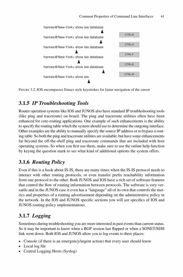
3.1.5 IP Troubleshooting ToolsRouter operation systems like IOS and JUNOS also have standard IP troubleshooting tools(like ping and traceroute) on board. The ping and traceroute utilities often have beenenhanced for core-routing applications. One example of such enhancements is the abilityto specify the routing table which the system should use to determine the outgoing interface.Other examples are the ability to manually specify the source IP address or to bypass a rout-ing table. So both the ping and traceroute utilities are available, but have some enhancementsfar beyond the off-the-shelf ping and traceroute commands that are included with hostoperating systems. So when you first use them, make sure to use the online help functionby keying the question mark to see what kind of additional options the system offers.
3.1.6 Routing PolicyEven if this is a book about IS-IS, there are many times when the IS-IS protocol needs tointeract with other routing protocols, or even transfer prefix reachability informationfrom one protocol to the other. Both JUNOS and IOS have a rich set of software featuresthat control the flow of routing information between protocols. The software is very ver-satile and in the JUNOS case it even has a “language” all of its own that controls the met-rics and properties of a routing advertisement depending on the administrative policy inthe network. In the IOS and JUNOS specific sections you will see specifics of IOS andJUNOS routing policy implementations.
3.1.7 LoggingSometimes during troubleshooting you are more interested in past events than current status.So it may be important to know when a BGP session last flapped or when a SONET/SDHlink went down. Both IOS and JUNOS allow you to log events to three places:
• Console (if there is an emergency/urgent action) that every user should know• Local log file• Central Logging Hosts (Syslog)
Common Properties of Command Line Interfaces 41
CTRL-B
CTRL-A
CTRL-F
CTRL-E
hannes@New-York> show isis database
CTRL-W
hannes@New-York> show isis database
hannes@New-York> show isis database
hannes@New-York> show isis database
hannes@New-York> show isis database
hannes@New-York> show isis
FIGURE 3.2. IOS encompasses Emacs style keystrokes for faster navigation of the cursor
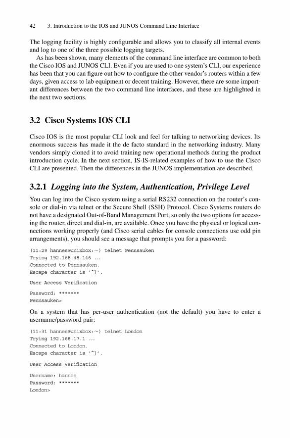
The logging facility is highly configurable and allows you to classify all internal eventsand log to one of the three possible logging targets.
As has been shown, many elements of the command line interface are common to boththe Cisco IOS and JUNOS CLI. Even if you are used to one system’s CLI, our experiencehas been that you can figure out how to configure the other vendor’s routers within a fewdays, given access to lab equipment or decent training. However, there are some import-ant differences between the two command line interfaces, and these are highlighted inthe next two sections.
3.2 Cisco Systems IOS CLI
Cisco IOS is the most popular CLI look and feel for talking to networking devices. Itsenormous success has made it the de facto standard in the networking industry. Manyvendors simply cloned it to avoid training new operational methods during the productintroduction cycle. In the next section, IS-IS-related examples of how to use the CiscoCLI are presented. Then the differences in the JUNOS implementation are described.
3.2.1 Logging into the System, Authentication, Privilege LevelYou can log into the Cisco system using a serial RS232 connection on the router’s con-sole or dial-in via telnet or the Secure Shell (SSH) Protocol. Cisco Systems routers donot have a designated Out-of-Band Management Port, so only the two options for access-ing the router, direct and dial-in, are available. Once you have the physical or logical con-nections working properly (and Cisco serial cables for console connections use odd pinarrangements), you should see a message that prompts you for a password:
(11:29 hannes@unixbox:�) telnet Pennsauken
Trying 192.168.48.146 ...
Connected to Pennsauken.
Escape character is ‘^]’.
User Access Verification
Password: *******
Pennsauken>
On a system that has per-user authentication (not the default) you have to enter a username/password pair:
(11:31 hannes@unixbox:�) telnet London
Trying 192.168.17.1 ...
Connected to London.
Escape character is ‘^]’.
User Access Verification
Username: hannes
Password: *******
London>
42 3. Introduction to the IOS and JUNOS Command Line Interface

IOS assigns every terminal session a privilege level between 1 and 15. You can displaythe privilege level anytime using the command show privilege:
London>show privilege
Current privilege level is 1
You cannot really cause any harm to the system or modify its configuration and dis-rupt traffic using a privilege level of 1. It is a privilege level dedicated to monitoring pur-poses only. If you want to modify the system’s configuration or turn on debugging forin-depth troubleshooting then you have to change this low privilege level. You can askyour network administrator to change the privilege level either for your user-id or for thespecific terminal line used to configure the router.
If you know the enable password you can jump immediately to privilege level 15, whichlets you do everything within the router, for example, changing the configuration, reboot-ing the box, resetting line cards, and so on:
London>enable
Password:
Then this will verify the enable privilege level:
London#show privilege
Current privilege level is 15
London#
Now you are in enable mode, which means that you have the full set of show and con-figuration commands available, as discussed in the next section.
3.2.2 IS-IS-related Show CommandsAt the end of the 1980s, IS-IS was being used as the routing protocol in a purely CLNPprotocol environment. This was also the time when Cisco because successful in the enter-prise marketplace with its multiprotocol router products. No one initially had in mind touse the IS-IS routing protocol for routing IP, not even the engineers at Cisco. Because ofthat, there is still some non-IP legacy in the user interface left. Moreover, Cisco alwayswanted to keep the router configurations portable from IOS release to IOS release, andthis desire had by that time caused configuration statements to become scattered over sev-eral different places in the user interface. In IOS, IS-IS support for CLNP came first, andsupport for IP, and the necessary troubleshooting tools, came later. So a lot of IS-IS-related commands are found under the show clns command and not at the showisis branch which would be more obvious from today’s perspective.
Do not be confused about the CLNP/CLNS abbreviations. CLNP is the NetworkLayer Protocol of the OSI suite. CLNS is the name of the entire suite of protocols. If onewants to compare this with the IP protocols then CLNP would be equivalent to IP andCLNS to TCP/IP which is also the name of the entire family of protocols and not limitedto only the IP and TCP protocol.
Cisco Systems IOS CLI 43
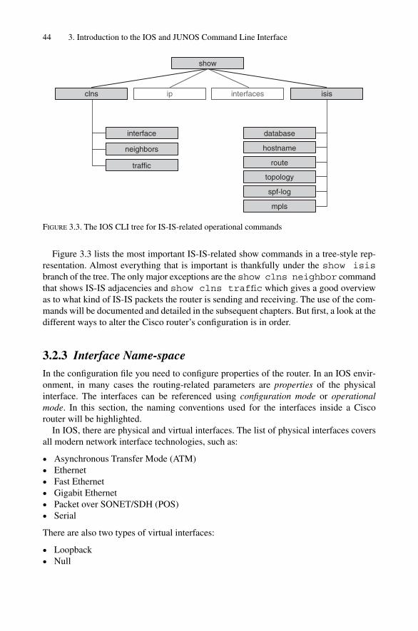
Figure 3.3 lists the most important IS-IS-related show commands in a tree-style rep-resentation. Almost everything that is important is thankfully under the show isisbranch of the tree. The only major exceptions are the show clns neighbor commandthat shows IS-IS adjacencies and show clns traffic which gives a good overviewas to what kind of IS-IS packets the router is sending and receiving. The use of the com-mands will be documented and detailed in the subsequent chapters. But first, a look at thedifferent ways to alter the Cisco router’s configuration is in order.
3.2.3 Interface Name-spaceIn the configuration file you need to configure properties of the router. In an IOS envir-onment, in many cases the routing-related parameters are properties of the physicalinterface. The interfaces can be referenced using configuration mode or operationalmode. In this section, the naming conventions used for the interfaces inside a Ciscorouter will be highlighted.
In IOS, there are physical and virtual interfaces. The list of physical interfaces coversall modern network interface technologies, such as:
• Asynchronous Transfer Mode (ATM)• Ethernet• Fast Ethernet• Gigabit Ethernet• Packet over SONET/SDH (POS)• Serial
There are also two types of virtual interfaces:
• Loopback• Null
44 3. Introduction to the IOS and JUNOS Command Line Interface
ip
show
interfaces isisclns
interface
neighbors
traffic
database
hostname
route
topology
spf-log
mpls
FIGURE 3.3. The IOS CLI tree for IS-IS-related operational commands

Virtual interfaces, in contrast to physical interfaces, have the nice feature that theynever go down. Because of this property, the loopback interface especially is used for ter-minating TCP-oriented routing and signalling protocols like BGP or MSDP. Because theloopback interface never goes down (as long as the router is functional), the routing pro-tocol packets are able to enter the router over any physical interface. After all, the func-tion of the IGP (OSPF, IS-IS) is to route around those interfaces that have gone down.This approach is much better than to terminate router 2 router sessions on interfaceaddresses.
The second virtual interface is the null interface. It also never goes down, but is usedfor different purposes. There are two applications for the null interface:
• Trashing traffic• Announcing aggregate routes
Generally, a router should forward packet traffic. However, there are times when arouter should route traffic to the “bit bucket”. A good example for this is traffic targetedto the RFC1918 private address spaces, which should never appear in packet headers onthe global public Internet. These addresses are intended for local use, and packets withthis source or destination address must not be forwarded to the Internet. It is commonpractice to install static routes for the private network addresses that point to a NULLinterface on each border router inside your Autonomous System (AS):
London# show running-configuration
[ … ]
ip route 10.0.0.0 255.0.0.0 Null0
ip route 172.16.0.0 255.240.0.0 Null0
ip route 192.168.0.0 255.255.0.0 Null0
In an IP environment, it is one of the duties of the routing protocols to report that a certain sub-net is unreachable. The routing protocols propagate this change and all routersalong the path recompute their IP routing tables. From an Internet perspective, this behav-iour is a real issue. In Chapter 10, there will be more details regarding why a re-computationof routes can be an expensive (in technical, not commercial terms) process. Typically, theInternet is not interested in an update that a /24 prefix from the other side of the planet isunavailable, because it keeps so many routers busy updating their new forwarding state.So the more common practice is to announce aggregate routes and to suppress all the spe-cific routes that may be internal to a network, as shown in Figure 3.4. But in order to existat all, routes, aggregate or not, need to refer to a next-hop interface, which leads to the nextrouter to forward traffic to. The null interface serves this next-hop purpose for aggre-gates: it is always up. And you get another feature for free – the null interface trashes alltraffic to destinations that do not have more specific routes. If sub-net (for example)192.168.33/24 is not known internally (that is, no more specific routes are known), andthere is a port-scanning source from the Internet, then the null interface trashes all thattraffic. However, the main purpose of this feature is to suppress announcements of specificroutes as shown in Figure 3.4, which shows the flapping of 192.168.44/24 towards theInternet.
Cisco Systems IOS CLI 45

Returning to physical interfaces, all of the high-end Cisco router models (7500 and12000 Series) have several slots that can hold up to 16 line cards depending on the exactrouter model. On the line card there may be one or more ports. The number of ports varieswith the line speed of the ports. The lower the line speed, the higher the port density.
The physical ports are referred to in a slot-number/port-number fashion. The follow-ing are examples of complete interface names in the IOS name-space:
• GigabitEthernet3/0• POS5/1• ATM0/0• Serial 1/0
The numbering of the slots and ports starts at 0. So the first slot position in the routerchassis is referred to as 0. In the digital world counting typically starts at zero.
The simplest way to access the properties and current state of an interface is to use theshow interface �interface-name� command:
London# show Interface POS3/0
POS3/0 is up, line protocol is up
Hardware is Packet over SONET
Description: “Interface to Amsterdam POS4/1”
Internet address is 172.16.25.1/30
MTU 4470 bytes, BW 155000 Kbit, DLY 100 usec, rely 255/255, load 1/255
Encapsulation HDLC, crc 16, loopback not set
Keepalive set (10sec)
Scramble enabled
Last input 00:00:00, output 00:00:07, output hang never
Last clearing of “show interface” counters never
Queueing strategy: fifo
Output queue 0/40, 0 drops; input queue 0/75, 0 drops
5 minute input rate 120457000 bits/sec, 28800 packets/sec
5 minute output rate 130429920 bits/sec, 26107 packets/sec
46 3. Introduction to the IOS and JUNOS Command Line Interface
Internet
Aggregate192.168/16
portscan to 192.168.33/24
192.168.44/24 flaps
San Fran
Atlanta
Miami
San Jose
FIGURE 3.4. Aggregate routes are typically advertised by AS border routers

412058846 packets input, 4066852672395 bytes, 0 no buffer
Received 0 broadcasts, 0 runts, 0 giants, 0 throttles
0 parity
1 input errors, 1 CRC, 0 frame, 0 overrun, 0 ignored, 0 abort
627685025 packets output, 4025356699702 bytes, 0 underruns
0 output errors, 0 applique, 4 interface resets
0 output buffer failures, 0 output buffers swapped out
3 carrier transitions
The output contains information about the Layer-2 encapsulation, maximum trans-mission unit (MTU), the current forwarding rate (expressed in packets and bytes), pluscounters for the aggregate number of bytes and packets that have been processed throughthis interface.
For IS-IS-related purposes, you will often see the interface names, for example, incommands like show clns neighbor:
London# show clns neighbor
System Id Interface SNPA State Holdtime Type Protocol
Frankfurt PO3/0 *PPP* Up 22 L2 IS-IS
Munich PO4/1 *PPP* Up 20 L2 IS-IS
3.2.4 Changing Router ConfigurationIn IOS you tell the router to take configuration input and to transfer it to the central con-figuration file using the configure command. The standalone configure commandwill prompt you to enter the way that you want to input the configuration file:
London#configure
Configuring from terminal, memory, or network [terminal]?
Enter configuration commands, one per line. End with CNTL/Z.
London(config)#
The memory option lets you source the configuration file from a memory storagedevice inside the router, such as flash-disks or the NVRAM. But a more typical way isfrom the network or from the terminal. From the network means that you have to specifya trivial FTP (TFTP) server and a filename, and the router will then attempt to pull downthe file using the TFTP protocol.
London#conf network
Address or name of remote host [255.255.255.255]? 192.168.1.1
Source filename [London-confg]?
Configure using tftp://192.168.1.1/London-confg? [confirm]
The most common way is to put the router into configuration mode and then enter theconfiguration statements manually from the terminal. This is the most likely way ofinteracting with the router in day-to-day operation:
London#configure terminal
Enter configuration commands, one per line. End with CNTL/Z.
London(config)#
Cisco Systems IOS CLI 47
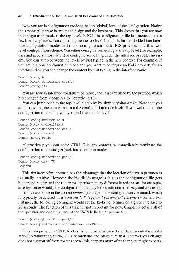
Now you are in configuration mode at the top (global) level of the configuration. Noticethe (config) phrase between the # sign and the hostname. This shows that you are nowin configuration mode at the top level. In IOS, the configuration file is structured into afew hierarchy levels. You can configure the top level, but this is further divided into inter-face configuration modes and router configuration mode. IOS provides only this two-level configuration scheme. You either configure something at the top level (for example,user and access information) or configure something under the interface or router hierar-chy. You can jump between the levels by just typing in the new context. For example, ifyou are in global configuration mode and you want to configure an IS-IS property for aninterface, then you can change the context by just typing in the interface name:
London(config)#
London(config)#interface pos5/3
London(config-if)
You are now in interface configuration mode, and this is verified by the prompt, whichhas changed from (config) to (config-if).
You can jump back to the top-level hierarchy by simply typing exit. Note that youare just exiting the context and not the configuration mode itself. If you want to exit theconfiguration mode then you type exit at the top level:
London(config)#router isis
London(config-router)#exit
London(config)#interface pos5/3
London(config-if)#exit
London(config)#exit
Alternatively you can enter CTRL-Z in any context to immediately terminate the configuration mode and get back into operation mode:
London(config)#interface pos5/3
London(config-if)# ^Z
London#
This flat hierarchy approach has the advantage that the location of certain parametersis usually intuitive. However, the big disadvantage is that as the configuration file getsbigger and bigger, and the router must perform many different functions (as, for example,an edge router would), the configuration file may look unstructured, messy and confusing.
In any case, once in the correct context, just type in the configuration command, whichis typically structured in a keyword N * [optional-parameter] parameter format. Forinstance, the following command would set the IS-IS hello timer on a given interface to20 seconds. The function of this timer is not important for now, Chapter 5 details all ofthe specifics and consequences of the IS-IS hello timer parameter.
London(config)#interface pos5/3
London(config-if)#isis hello-interval 20<ENTER>
Once you press the <ENTER> key the command is parsed and then executed immedi-ately. So whatever you do, think beforehand and make sure that whatever you changedoes not cut you off from router access (this happens more often than you might expect).
48 3. Introduction to the IOS and JUNOS Command Line Interface

There are configuration changes that require an entire set of commands to be entered on a router. And if you enter them in the wrong order, then your in-band terminal (telnet)session might be cut off. A good example of this is authentication of routing updates.Typically, you have to specify a shared secret password that is stored locally on the router.The second configuration step is a reference to the password, which makes the router sendauthenticated information, but also makes the router expect authenticated routing informa-tion with the shared secret. Imagine what happens if you mix up the order: first you tell therouter that everything has to be authenticated, and so is also expected to arrive authenti-cated. What happens is that you will receive a few Hello messages and then your routerdrops the adjacency because nothing has been actually authenticated because there is nopassword yet! If you are relying on the network for configuration access, hope that thereis someone local you can reach to correct the problem through a direct console connection.
The authentication example is basically a two-step configuration transaction. Theterm transaction was borrowed from SQL database environments, which faced the prob-lem everyday that structured, multi-field data are not entered and stored all at once.Because of transient conditions like two users modifying the same database records atthe same time, corrupted data was often the result. All modern databases offer transac-tional integrity, which locks the database until the entire transaction is finished. In therouter world, this would mean that you can finish all the commands that belong togetherfor a desired functionality and the session would never be disrupted. Unfortunately, theIOS user interface does not give you transactional integrity, which means that you can-not configure a set of commands in any order without risk of disrupting your in-band tel-net session. For a configuration transaction that involves more than one configurationstep, finding out the proper order of the commands is a daunting task and sometimes noteven possible! This is especially true if machines like provisioning systems or config-uration robots are doing the configuration of the router more or less unsupervised, thenthe provisioning software gets infinitely complex.
What can be done about this IOS immediate-change feature? The best current practiceis that the provisioning systems overwrite not the active configuration, but the Ciscostartup-configuration file and reboot the router at 3:00 am in the morning. Modifying thestartup-configuration file has the advantage that the configuration does not get effectiveimmediately. As the name implies, it only becomes active the next time the router isrebooted. The following command loads a file named “London-startup-config” and over-writes the startup configuration file of the router:
London#copy tftp://192.168.1.1/London-startup-config startup-config
What you have to do for this new configuration to become active is to reboot the router(either automated or manually). This of course implies that you have designed enoughredundancy into the network so that you do not cause any major outages by the routergoing out of service for the approximately 3 to 4 minutes it takes for the reboot, which isa common time for large core routers like the GSR 12000 series:
London#reload
Proceed with reload? [confirm]
Connection closed by foreign host.
Cisco Systems IOS CLI 49
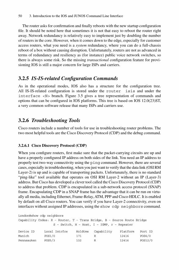
The router asks for confirmation and finally reboots with the new startup configurationfile. It should be noted here that sometimes it is not that easy to reboot the router rightaway. Network redundancy is relatively easy to implement just by doubling the numberof routers in the core. However, when it comes down to the edge, especially for customeraccess routers, what you need is a system redundancy, where you can do a full-chassisreboot of a box without causing disruption. Unfortunately, routers are not as advanced interms of redundancy and resiliency as (for instance) public voice network switches, sothere is always some risk. So the missing transactional configuration feature for provi-sioning IOS is still a major concern for large ISPs and carriers.
3.2.5 IS-IS-related Configuration CommandsAs in the operational modes, IOS also has a structure for the configuration tree. All IS-IS-related configuration is stored under the router isis and under theinterface <N> branch. Figure 3.5 gives a tree representation of commands andoptions that can be configured in IOS platforms. This tree is based on IOS 12.0(23)ST,a very common software release that many ISPs and carriers use.
3.2.6 Troubleshooting ToolsCisco routers include a number of tools for use in troubleshooting router problems. Thetwo most helpful tools are the Cisco Discovery Protocol (CDP) and the debug command.
3.2.6.1 Cisco Discovery Protocol (CDP)
When you configure routers, first make sure that the packet-carrying circuits are up andhave a properly configured IP address on both sides of the link. You need an IP address toproperly test two-way connectivity using the ping command. However, there are severalcases, especially in troubleshooting, when you just want to verify that the data link (OSI RMLayer-2) is up and is capable of transporting packets. Unfortunately, there is no standard“ping-like” tool available that operates on OSI RM Layer-2 without an IP (Layer-3)address. But Cisco has developed a clever tool called the Cisco Discovery Protocol (CDP)to address that problem. CDP is encapsulated in a sub-network access protocol (SNAP)frame. Encapsulating CDP in a SNAP frame has the advantage that it can be run on virtu-ally all media, including Ethernet, Frame-Relay, ATM, PPP and Cisco-HDLC. It is enabledby default on all Cisco routers. You can verify if you have Layer-2 connectivity, even oninterfaces without assigned IP addresses, using the show cdp neighbors command.
London#show cdp neighbors
Capability Codes: R – Router, T – Trans Bridge, B – Source Route Bridge
S – Switch, H – Host, I – IGMP, r – Repeater
Device ID Local Intrfce Holdtme Capability Platform Port ID
Munich POS1/0 171 R 12416 POS6/0
Pennsauken POS5/3 132 R 12416 POS12/0
50 3. Introduction to the IOS and JUNOS Command Line Interface
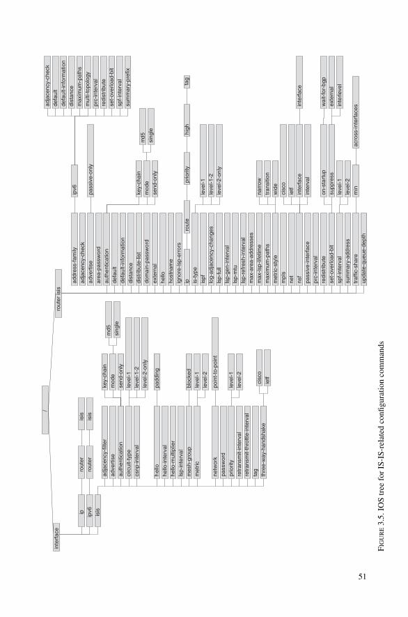
/
rout
er is
isin
terf
ace
isis
auth
entic
atio
n
defa
ult-
info
rmat
ion
dist
ance
dist
ribut
e-lis
t
exte
rnal
hello
host
nam
e
igno
re-ls
p-er
rors
is-t
ype
log-
adja
cenc
y-ch
ange
s
lsp-
gen-
inte
rval
lsp-
mtu
lsp-
refr
esh-
inte
rval
max
-are
a-ad
dres
ses
max
-lsp-
lifet
ime
max
imum
-pat
hs
met
ric-s
tyle
mpl
s
net
pass
ive-
inte
rfac
e
prc-
inte
rval
redi
strib
ute
set-
over
load
-bit
spf-
inte
rval
sum
mar
y-ad
dres
s
traf
fic-s
hare
upda
te-q
ueue
-dep
th
key-
chai
n
mod
e
send
-onl
y
md5
sing
le
adv
ertis
e
adja
cenc
y-ch
eck
addr
ess-
fam
ily
area
-pas
swor
d
defa
ult
dom
ain-
pass
wor
d
ip ispf
lsp-
full
leve
l-1
leve
l-1-2
leve
l-2-o
nly
nsf
cisc
o
ietf
inte
rfac
e
inte
rval
inte
rfac
e
ipv6
mul
ti-to
polo
gy
adja
cenc
y-ch
eck
defa
ult-
info
rmat
ion
defa
ult
dist
ance
max
imum
-pat
hs
prc-
inte
rval
redi
strib
ute
set-
over
load
-bit
spf-
inte
rval
sum
mar
y-pr
efix
rout
epr
iorit
yhi
ghta
g
on-s
tart
upw
ait-
for-
bgp
supp
ress
exte
rnal
inte
rleve
l
min
acro
ss-in
terf
aces
leve
l-1
leve
l-2
wid
e
tran
sitio
n
narr
ow
pass
ive-
only
ipro
uter
isis
ipv6
rout
eris
is
adja
cenc
y-fil
ter
adve
rtis
e
auth
entic
atio
n
circ
uit-
type
csnp
-inte
rval
hel
lo
hello
-inte
rval
hello
-mul
tiplie
r
lsp-
inte
rval
mes
h-gr
oup
met
ric
netw
ork
pass
wor
d
prio
rity
retr
ansm
it-in
terv
alre
tran
smit-
thro
ttle-
inte
rval
tag
thre
e-w
ay-h
ands
hake
key-
chai
n
mod
e
send
-onl
y
md5
sing
le
cisc
o
ietf
poin
t-to
-poi
nt
bloc
ked
padd
ing
leve
l-1
leve
l-1-2
leve
l-2-o
nly
leve
l-1
leve
l-2
leve
l-1
leve
l-2
FIG
UR
E3.
5.IO
S tr
ee f
or I
S-IS
-rel
ated
con
figur
atio
n co
mm
ands
51
The output shows you the hostname of the neighbouring device, the local interface to theremote device, the “platform name” of the router, and the port that the remote device isusing for your connection. The port is particularly interesting if you are doing low-leveltroubleshooting with field personnel at the remote end. You can direct them to the portconfiguration or even submit a configuration snippet that the remote personnel shouldload on the router. Often field personnel are not used to configuring routers, and if asked toconfigure an IP address or a certain line card setting, they sometimes decline. This is notintended as an insult to field teams, who can’t be experts in everything, but it is a fact of life.However, knowing the interface name, you can say to the field team “This is the config-uration. Just plug in your laptop, login, do a configure terminal and then copy andpaste the configuration in.” This is a simple procedure that every field technician feelscomfortable with. CDP also conveys additional parameters like software versions and IPaddresses. The show cdp neighbor detail command reveals those details:
London#show cdp neighbor detail
------------
Device ID: Munich
Entry address(es):
IP address: 192.168.48.151
Platform: cisco 12416, Capabilities: Router
Interface: POS1/0, Port ID (outgoing port): POS6/0
Holdtime : 161sec
Version :
Cisco Internetwork Operating System Software
IOS (tm) GS Software (GSR-P-M), Version 12.0(17)ST6
Copyright (c) 1986-2002 by cisco Systems, Inc.
Compiled Tue 07-May-02 00:49 by dchih
In the show cdp neighbor command there is also a column giving some infor-mation about the router’s capabilities. Cisco of course has a whole variety of productsavailable that process packets at many layers of the OSI Reference Model. The showcdp neighbor detail command shows you in a capabilities line at which layersthe device operates. For Internet routers, which are according to the OSI ReferenceModel Layer-3 devices, the word “Router” should be listed here.
3.2.6.2 Debugging
Cisco IOS was the first commercial router operating system that had very powerfuldebugging messages available. The debugging sub-system of the router works very simply. You enter a structured command like debug <keyword>. This sets an inter-nal flag in the software to log every event that matches that keyword. The output is thenwritten to a local logging buffer. The administrator can read out the logging buffer inreal-time on his vty (virtual terminal, just another term for telnet) session or on the con-sole. Additionally, all logs can be stored on an external syslog server and logged by therouter to this particular server with the syslog protocol. The debugging flags are struc-tured in a tree-like fashion, just like the operational and configuration commands. Thestructure of debug-tree is shown in Figure 3.6.
52 3. Introduction to the IOS and JUNOS Command Line Interface

For example, if you do not know if your router is sending and receiving Hello packets,you could set a debug flag to record all output in a logging buffer. Make sure that you arein privileged (enable) mode before setting any debug flag, otherwise the system wouldrefuse to do so. This is a kind of safety check to avoid abuse and service degradation byexcessive logging, which places an additional load on the router. The assumption is ifyou are given the enable password then you should know what you are doing. The set-ting of certain debug flags can even make the router freeze because it is so busy writinglog messages to the logging buffer. Here is an IS-IS example of debug use:
London#debug isis adj-packets
IS-IS Adjacency related packets debugging is on
London#
Initially, nothing seems to be happening because you do not see any output on thescreen. However, the system is logging sent or received Hello packets, which are thepackets that bring up IS-IS adjacencies. You can examine the contents of the loggingbuffer by issuing a show logging command:
London#show logging
Syslog logging: enabled (2 messages dropped, 0 messages rate-limited,
0 flushes, 0 overruns)
Console logging: level debugging, 1894 messages logged
Monitor logging: level debugging, 143 messages logged
Buffer logging: level debugging, 1894 messages logged
Logging Exception size (4096 bytes)
Trap logging: level informational, 1810 message lines logged
Cisco Systems IOS CLI 53
debug
isisip
access-list
bgp
interface
tcp
adj-packets
checksum-errors
local-updates
mpls
protocol-errors
snp-packets
spf-statistics
spf-triggers
update-packets
traffic-engadvertisements
events
terse
authentication
nsf
information
cisco
detail
ietf
spf-events
FIGURE 3.6. IOS CLI for IS-IS-related debug commands

Log Buffer (16384 bytes):
*Jul 12 21:38:27.216 UTC: ISIS-Adj: Sending serial IIH on Serial3/0, length 4469
*Jul 12 21:38:29.056 UTC: ISIS-Adj: Rec serial IIH from *HDLC* (Serial3/0),
cir type L2, cir id 01, length 58
*Jul 12 21:38:29.056 UTC: ISIS-Adj: rcvd state UP, old state UP, new state UP
*Jul 12 21:38:29.056 UTC: ISIS-Adj: Action � ACCEPT
The bottom of the output displays the most recent events and which parts of the soft-ware (here it is the ISIS-Adj sub-system) logged the message. If you do not want toalways monitor the logging buffer, another technique is to open up a second telnetsession to the router. You use the first for troubleshooting the router and changing theconfiguration, and the second to read the output of the debugger. Additionally, becauserepeatedly typing in the command show logging is a bit tedious, you can make therouter log all the messages to the second telnet session. You can make the router do thisby issuing the command terminal monitor:
London#terminal monitor
London#
*Jul 12 21:51:20.072 UTC: ISIS-Adj: Sending serial IIH on Serial3/0, length 4469
*Jul 12 21:51:21.228 UTC: ISIS-Adj: Rec serial IIH from *HDLC* (Serial3/0),
cir type L2, cir id 01, length 58
*Jul 12 21:51:21.228 UTC: ISIS-Adj: rcvd state UP, old state UP, new state UP
*Jul 12 21:51:21.228 UTC: ISIS-Adj: Action � ACCEPT
If you now issue a show logging command, you see your most recent logs as well as an indication that the system is writing the logging buffer to a virtual terminal (telnetsession):
London#show logging
Syslog logging: enabled (2 messages dropped, 0 messages rate-limited,
0 flushes, 0 overruns)
Console logging: level debugging, 1856 messages logged
Monitor logging: level debugging, 109 messages logged Logging to: vty2(91)
Buffer logging: level debugging, 1856 messages logged
Logging Exception size (4096 bytes)
Trap logging: level informational, 1808 message lines logged
Additionally, it may sometimes be interesting to see what kind of debug flags therouter has set. The show debugging command displays you all debug flags currentlycatching events, which are logged to the logging buffer:
London#show debugging
CLNS:
IS-IS Adjacency related packets debugging is on
London#
54 3. Introduction to the IOS and JUNOS Command Line Interface
Once you have finished your troubleshooting session, make sure that you turn offdebugging! Excessive debugging may degrade performance of the control plane andhence seriously harm the system. The quickest command to turn off all debug flags is theundebug all command.
London#undebug all
All possible debugging has been turned off
London#
3.2.7 Routing Policy and Filtering of RoutesA router running all different kinds of routing protocols is still not enough for today’smarketplace. Modern routing OSs have a strong support for controlling what kinds ofroutes are accepted and advertised in turn to neighbours. What sounds so easy to do atfirst is actually one of the most complex parts of a vendor’s routing code. Handling rout-ing policy often requires a dedicated language to specify every detail of what type ofrouting policy you need in your routing domain.
Looking at the IOS command line style and hierarchy, you can see that there is no sin-gle place where routing policies are configured. That’s no big surprise – with IOS, becauseof its multiprotocol nature, each routing protocol implements its own routing policy pro-cessing as part of the protocol’s specific routing code. So one policy module is there forRIP, one for IS-IS, and another one for BGP. This design choice is actually very conven-ient as long as your routing policy stays simple. However, for more complex policies,this approach quickly becomes difficult to maintain, given the different styles sometimesused in the protocol’s redistribution policy. With the rise of BGP as an interdomain pro-tocol and the protocol for policy processing, it was clear that a new, common way of con-figuring routing policies had to be implemented in IOS. That common routing paradigmin IOS is called route-maps. We will discuss only IS-IS-specific routing policies androute-maps, and only briefly. But this is fine. Due to the way IS-IS is used by serviceprovider’s routing policies, which is as a pure topology discovery protocol, there are notmany IP routes in the IS-IS routing protocol to worry about distributing, because BGPdoes that job much better. We do not need policy processing in IS-IS as much as wewould need it in a book about BGP. Typically, in an ISP’s IS-IS network, there is onlyone place where policy processing takes place: when passing down routes from IS-ISLevel 2 to Level 1. But let’s keep that aside for a while – there is more about IS-IS hier-archical routing levels in Chapters 4 and 12.
A good example of an IS-IS protocol-specific policy is the redistribute isis iplevel-2 into level-1 distribute-list 101 metric-style widecommand. This seems like a very complex statement, but it is really quite simple. It justtells the router to send (redistribute) any IS-IS Level-2 IP routing information to theLevel-1 routers (isis ip level-2 into level-1) and use a larger metric fieldthan originally specified (metric-style wide). The details of the redistribute command are covered in Chapter 12. For now, the important part of the command is thedistribute-list 101 statement. The distribute-list refers to an extended-access-list,which is a list of IP prefixes. In IOS, many sometimes complex policy operations can be
Cisco Systems IOS CLI 55

done with a single command plus an extended-access-list. In the following example, theextended-access-list referred to by the distribute-list 101 command is shown:
London# show running-config
[ … ]
access-list 101 permit ip 192.168.1.0 0.0.0.255 any
access-list 101 permit ip 192.168.3.0 0.0.0.255 any
[ … ]
Confusingly, IOS can also use route-maps, which are the more flexible IOS routingpolicy language. The route-map command introduces a multi-line sequence of match/action pairs ordered by a sequence number. The most important clauses are the matchand set statements. These allow you to match on arbitrary prefix properties, such as the interface it was learned (received) from, associated BGP community lists, or evenreference other access lists. The permit anddeny keyword control the action if and whena prefix is matched. The permit keyword means that the prefix generally is accepted bythe router and can only be modified by means of the set command. The deny keywordmeans that a prefix is dropped upon match. An example route-map looks like this:
London# show running-config
[ … ]
route-map hannes permit 10
match community 2
set metric 20
route-map hannes deny 20
match community 13
[ … ]
3.2.8 Further DocumentationThere is a huge set of IOS-related material around. Probably the best starting site isCisco’s online manuals, which can be accessed at http://www.cisco.com/univercd/cc/td/doc/product/software/index.htm.
3.3 Juniper Networks JUNOS CLI
The IOS-style CLI is the standard in the industry and many vendors copied it for their ownproducts. When Juniper Networks released the first version of its routing software namedJUNOS Internet software, many industry observers believed that it would be a clone ofthe IOS CLI as well. However, the engineers at Juniper Networks who were in charge ofthe user interface did not want to create just another clone of the IOS CLI. Being mostlyex-Cisco employees, they had developed a good understanding of the limitations (espe-cially the provisioning aspect) of the IOS software. For them it was crystal clear that theywanted to create something new. So they replaced parts of the user interface that did notwork well and kept the properties that made IOS so successful.
56 3. Introduction to the IOS and JUNOS Command Line Interface

3.3.1 Logging into the System and AuthenticationWhen you first log into a router running JUNOS, the first difference you see from IOS isthat the system prompts you in a UNIX fashion for a username and a password:
(20:45 hannes@unixbox:�) telnet frankfurt
Trying 192.168.77.12...
Connected to frankfurt.
Escape character is ‘^]’.
Frankfurt (ttyp0)
login: hannes
Password: *********
--- JUNOS 5.3R2.4 built 2002-06-03 18:59:57 UTC
hannes@Frankfurt>
This is because the underlying base OS for JUNOS is a heavily modified FreeBSD.FreeBSD is a free UNIX clone just like the more popular Linux UNIX. Your can get fur-ther information about FreeBSD at http://www.freebsd.org/.
But make no mistake: JUNOS and the original FreeBSD are different OSs, and largeparts of the networking-related kernel routines have been changed. FreeBSD is targetedfor a host operating system environment, much like a networked PC. Typically, hostoperating systems have:
• A single routing table• 1–3 network interfaces• Tens of routes to handle
An operating system targeted for both edge and core routing functions has to handlemany more of each. Specifically, these needs are:
• Hundreds of routing tables• Thousands of interfaces• 100,000s of routes
However, there are still lots of things that remained in JUNOS, such as all the net-working tools (telnet, SSH, ping and traceroute utilities) or, as in the previous example,the login procedure.
Once you are logged in with your username, you have a set of privileges that are asso-ciated with your username, similar to IOS. You can display those privileges by issuing ashow cli authorization command.
hannes@Frankfurt> show cli authorization
Current user: ‘hannes’ class ‘super-user’
Permissions:
admin -- Can view user accounts
admin-control -- Can modify user accounts
clear -- Can clear learned network information
Juniper Networks JUNOS CLI 57
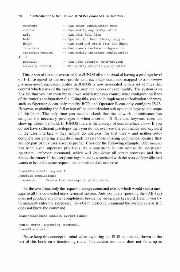
configure -- Can enter configuration mode
control -- Can modify any configuration
edit -- Can edit full files
field -- Special for field (debug) support
floppy -- Can read and write from the floppy
interface -- Can view interface configuration
interface-control -- Can modify interface configuration
[ … ]
security –- Can view security configuration
security-control –- Can modify security configuration
This is one of the improvements that JUNOS offers. Instead of having a privilege levelof 1–15 assigned to the user-profile with each IOS command mapped to a minimumprivilege-level, each user profile in JUNOS is now associated with a set of flags thatcontrol which parts of the system the user can access or even modify. The system is soflexible that you can even break down which user can control what configuration lines of the router’s configuration file. Using this, you could implement authorization schemes,such as Operator A can only modify BGP, and Operator B can only configure IS-IS.However, explaining the full extent of the authorization sub-system is beyond the scopeof this book. The only time you need to check that the network administrator hasassigned the necessary privileges is when a certain IS-IS-related keyword does not show up where it should. In JUNOS there is the concept of user interface views. If youdo not have sufficient privileges then you do not even see the commands and keyword in the user interface – they simply do not exist for that user – and neither auto-complete nor entering a question mark reveals those missing commands because they are not part of this user’s access profile. Consider the following example. User hanneshas been given superuser privileges. As a superuser, he can access the requestsystem reboot command, which will shut down all server processes and then reboot the router. If the user frank logs in and is associated with the read-only profile andwants to issue the same request, the command does not exist:
frank@Frankfurt> request ?
Possible completions:
message Send a text message to other users
For the user frank only the request message command exists, which would send a mes-sage to all the connected users terminal session. Auto complete (pressing the TAB key)does not produce any other completions beside the message keyword. Even if you tryto manually enter the request system reboot command the system acts as if itdoes not know the command.
frank@Frankfurt> request system reboot
^
syntax error, expecting <command>.
frank@Frankfurt>
Please keep this concept in mind when exploring the IS-IS commands shown in therest of this book on a functioning router. If a certain command does not show up as
58 3. Introduction to the IOS and JUNOS Command Line Interface

expected, it could be that the network administrator has not granted you the access levelrequired to reveal one of the commands you might be looking for.
3.3.2 IS-IS-related Show CommandsOnce you are logged into the JUNOS system, you are first placed into operational mode, as in IOS. You know that you are in operational mode by looking at the prompt. If the prompt is terminated using a “�” character then you are in operational mode,just as in IOS:
hannes@Frankfurt>
Figure 3.7 shows the commands that are available in operational mode.Unlike the Cisco implementation of the IS-IS Protocol, the JUNOS version was written
only to transport IP and not CLNP reachability information. Therefore all operationalcommands are accommodated under the show isis branch of the CLI tree. Almost
Juniper Networks JUNOS CLI 59
route
show
interfacesisis
adjacencydatabase
interface
route
spf
statistics
briefdetailextensiveinstance
briefdetailextensiveinstancelevel
briefdetailextensiveinstance
instance
topology unicastmulticast
brief
log
results
instance
chassis cli
topology
topology
topology
ipv6-unicast
unicast
multicastipv6-unicast
unicastmulticast
ipv6-unicast
unicast
multicast
ipv6-unicast
logical-router
logical-router
logical-router
logical-router
logical-router
inetinet6
instance
levellogical-router
instance
levellogical-router
instance
levellogical-router
logical-router
hostname
FIGURE 3.7. The JUNOS CLI tree for IS-IS-related operational commands

every command in the hierarchy has a command-modifier as the last argument. Commandmodifiers control the level of output that the command provides to the user. For example,if you issue a show isis interface brief command, then the output shows youall interfaces that have IS-IS configured. The keyword brief at the end of the commandtells the router that you only wish to see-minimal information available for the interface:
hannes@Frankfurt> show isis interface brief
IS-IS interface database:
Interface L CirID Level 1 DR Level 2 DR L1/L2 Metric
so-2/1/0.0 2 0x2 Disabled Point to Point 10/3500
so-3/0/0.0 2 0x1 Disabled Point to Point 10/240
[ … ]
The extensive command modifier tells the router that you wish to see all informationthat the router maintains for a given interface including timers and much more:
hannes@Frankfurt> show isis interface extensive
IS-IS interface database:
so-2/1/0.0
Index: 16, State: 0x6, Circuit id: 0x1, Circuit type: 2
LSP interval: 100ms, CSNP interval: disabled
Level 2
Adjacencies: 1, Priority: 64, Metric: 3500
Hello Interval: 9 s, Hold Time: 27 s
so-3/0/0.0
Index: 14, State: 0x6, Circuit id: 0x1, Circuit type: 2
LSP interval: 100ms, CSNP interval: disabled
Level 2
Adjacencies: 1, Priority: 64, Metric: 240
Hello Interval: 9s, Hold Time: 27s
[ … ]
JUNOS interface names, like so-3/0/0.0, are also different than in IOS. In JUNOSthere is an underlying interface naming convention that has to be learned to correctlyconfigure the router and interpret the CLI output.
3.3.3 Interface Name-spaceJUNOS has four types of interfaces:
• Logical interfaces• Permanent interfaces• Virtual interfaces• Physical interfaces
The only logical interfaces inside JUNOS are instances of the loopback (lo0) inter-face, used for terminating control traffic like BGP, MSDP, management protocols like theSimple Network Management Protocol (SNMP), Telnet and Secure Shell (SSH). Thereis no NULL interface as in IOS that can be used to trash traffic. Instead, JUNOS has aspecial next-hop type for trashing traffic. JUNOS also has a special aggregate facility for
60 3. Introduction to the IOS and JUNOS Command Line Interface

the announcement of aggregate routes. However, a detailed explanation of these isbeyond the scope of this book.
The two permanent interfaces are the fxp0 and the fxp1 interfaces. Juniper NetworksRouting Engines (REs) are off-the-shelf, industry-standard PCs that take care of the careand feeding of the Packet Forwarding Engine (PFE). The REs have two Fast-EthernetInterfaces, one of them exposed to the outside world and one of them connected to thepacket-forwarding complex. Those Fast Ethernet Interfaces are based on Intel chipsetsand, in good FreeBSD tradition, those interfaces are referred to using the name fxp.
You can configure the fxp0 interface (the one exposed to the outside world) only.Don’t attempt to configure the fxp1 interfaces: your configuration change might very wellinterfere with internal RE to PFE communication. The typical application of the fxp0interface is to use it for out-of-band (OOB) management access. This interface can beused to send out all kinds of routing and signalling information, however, it cannot be usedto carry transit traffic. Figure 3.8 shows why JUNOS does not allow this. Traffic enteringthe router would have to be squeezed through the fxp1 interface (the internal FastEthernet Segment), which is dedicated to carrying control traffic only. Whenever the PFErealizes that a route should use the fxp1 port as a next-hop for transit traffic, then the fab-ric generates an ICMP unreachable packet back to the sender. Because of this designchoice, you get a modest amount of security for your management segment, which nowcannot be accessed from the Internet.
JUNOS makes a clear distinction between physical interfaces and logical interfaces.On the physical interface level you can control properties of OSI Reference Model Layer1 and 2. Examples of such properties are:
• Link MTU size• Encapsulation method• Frame checksum computation• Layer 1 framing format• Full/Half duplex operation
Juniper Networks JUNOS CLI 61
Internet
172.
16.1
3/24RE
fxp0fxp1PFE
172.16.13/24 via FXP1 -> REJECT
FIGURE 3.8. Sub-nets connected to the fxp0 management port are not reachable from the Internet

Logical interfaces typically have properties from OSI Reference Model Layer 3.Examples of such properties are:
• IP addresses/Prefix lengths• ISO NETs• Filters• ICMP behaviour (redirect suppression)• And many more…
First, consider the interface naming for the physical interfaces. (The logical interfacesare a superset of the physical interfaces, so we start with the simple things first). JUNOShas a structure similar to IOS as far as the interface naming is concerned: the first two letters always describe what media type the interface is. Table 3.1 shows the two-letterabbreviations and the corresponding fully specified interface media types. What follows(after a dash) are three numbers separated by slashes. The three numbers represent the FPCSlot, the PIC slot and the port number. If you are not familiar with Juniper Networkshardware don’t worry: the FPC card is a carrier card like the VIP card for the Cisco 7500Series. The FPC mostly contains buffering memory as well as classification and queuinghardware. The PIC card is then mounted on top of the FPC card. This is how the FPC gotits name of Flexible PIC Concentrator.
PIC is an abbreviation for Physical Interface Connector. It is the place where the fibreand copper lines are connected to the router. The reason the physical lines do not directlyconnect to the FPC is flexibility. You can populate your FPC with PICs of arbitrary media-types like Ethernet, Packet over SONET/SDH and ATM in a mix-and-match fashion.
Figure 3.9 shows how a physical port is referenced in JUNOS. The first part is theinterface media type: “at” stands for an ATM interface. It is inserted into FPC chassis slotNumber 3 (counting starts at 0, so the first slot is slot #0 and slot #3 is the fourth slot) onthe second PIC slot (#1) and finally on the third port (#2).
The good news about the JUNOS interface-naming scheme is that it is consistentthroughout all the platforms (M- and T-Series). On every platform from the little M5 upto the T640, the interface naming stays consistent: FPC, then PIC, and finally the port number. Below is an example of how the status of an interface is displayed using theshow interface �interface-name� command:
hannes@Pennsauken> show interfaces so-0/0/0
Physical interface: so-0/0/0, Enabled, Physical link is Up
62 3. Introduction to the IOS and JUNOS Command Line Interface
TABLE 3.1. JUNOS uses two-letter names for its different interface media types.JUNOS interface abbreviation Interface media/type
at ATM over SONET/SDH portse1 E1 portse3 E3 portsfe Fast Ethernet portsso SONET/SDH portst1 T1 portst3 DS-3 portsge Gigabit Ethernet portst3 Aggregated Ethernet ports

Interface index: 11, SNMP ifIndex: 14
Description: to-New-York-so-7/0/1
Link-level type: Cisco-HDLC, MTU: 4474, Clocking: Internal, SDH mode,
Speed: OC3, FCS: 16,
Payload scrambler: Disabled
Device flags : Present Running
Interface flags: Point-To-Point SNMP-Traps
Link flags : Keepalives
Keepalive settings: Interval 10 seconds, Up-count 1, Down-count 3
Keepalive: Input: 507921 (00:00:06 ago), Output: 510818 (00:00:05 ago)
Last flapped : 2002-08-07 13:58:35 CEST (2d 08:58 ago)
Input rate : 42783824 bps (21297 pps)
Output rate : 58047120 bps (15777 pps)
SONET alarms : None
SONET defects : None
3.3.4 IS-IS-related Configuration CommandsLike IOS, JUNOS has a configuration mode. You need to get into configuration mode first(if you have the related privileges to do so) to modify the router’s central configuration file.
You can get into configuration mode by issuing the configure command:
hannes@Frankfurt>] configure
Entering configuration mode
[edit]
hannes@Frankfurt#
You know you are in configuration mode in two ways – first the prompt terminateswith the hash (#) sign, and second the line before the prompt displays the configurationlevel (or context) you are in. In JUNOS there is a multi-level hierarchy of configurationcommands. This is unlike Cisco IOS where the configuration file is only structured intotwo levels. Figure 3.10 shows a full overview of the IS-IS-related configuration optionsavailable in JUNOS configuration mode.
All options are under the protocols isis {} branch. When you want to configurethe protocols isis {} context you have to change to that context first using the edit command.
Juniper Networks JUNOS CLI 63
Physical interfaces have standard names
– Type
– FPC slot
– PIC slot
– Port number
at 3 2 1
FIGURE 3.9. JUNOS interface names are notated in interface-type/FPC slot/PIC slot/port numberorder
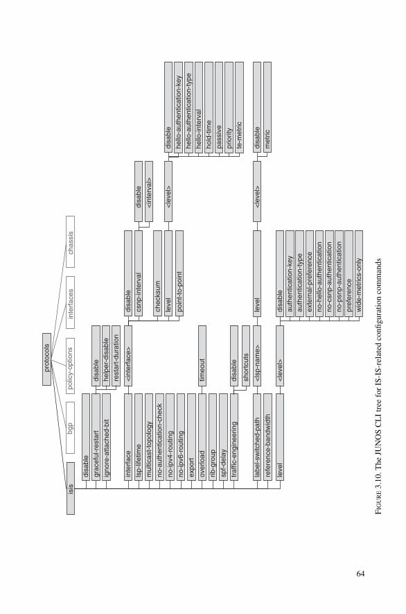
bgp
prot
ocol
s
polic
y-op
tions
isis
disa
ble
expo
rt
grac
eful
-res
tart
leve
l
mul
ticas
t-to
polo
gy
no-ip
v6-r
outin
g
over
load
disa
ble
help
er-d
isab
le
rest
art-
dura
tion
timeo
ut
<ls
p-na
me>
inte
rfac
esch
assi
s
igno
re-a
ttach
ed-b
it
inte
rfac
e
labe
l-sw
itche
d-pa
th
no-a
uthe
ntic
atio
n-ch
eck
lsp-
lifet
ime
no-ip
v4-r
outin
g
refe
renc
e-ba
ndw
idth
rib-g
roup
spf-
dela
y
traf
fic-e
ngin
eerin
g
<in
terf
ace>
disa
ble
csnp
-inte
rval
<in
terv
al>
disa
ble
chec
ksum
leve
l
poin
t-to
-poi
nt
<le
vel>
disa
ble
hello
-aut
hent
icat
ion-
key
hello
-aut
hent
icat
ion-
type
hello
-inte
rval
hold
-tim
e
pass
ive
prio
rity
te-m
etric
leve
l<
leve
l>
disa
ble
shor
tcut
s
disa
ble
met
ric
<le
vel>
disa
ble
auth
entic
atio
n-ke
yau
then
ticat
ion-
type
exte
rnal
-pre
fere
nce
no-c
snp-
auth
entic
atio
nno
-psn
p-au
then
ticat
ion
no-h
ello
-aut
hent
icat
ion
pref
eren
cew
ide-
met
rics-
only
FIG
UR
E3.
10.T
he J
UN
OS
CL
I tr
ee f
or I
S-IS
-rel
ated
con
figur
atio
n co
mm
ands
64

[edit]
hannes@Frankfurt# edit protocols isis
[edit protocols isis]
hannes@Frankfurt#
The context displayed between the brackets changes to the protocols isiscontext. Imagine the configuration hierarchy as a file system, and the different contextsare the directories. The edit command behaves like the UNIX cd command, which isused for changing directories.
If you want to go from there and edit the IS-IS Level-2 configuration then you simplyenter the following command:
[edit protocols isis]
hannes@Frankfurt# edit level 2
[edit protocols isis level 2]
hannes@Frankfurt#
You can go back to the top level using the top command. The top commandcompares best to the UNIX cd / command which puts you at the root of a UNIX filesystem tree:
[edit protocols isis level 2]
hannes@Frankfurt# top
[edit]
hannes@Frankfurt#
If you want to exit the configuration mode, type at any level exit configuration-mode, which puts you back in operation mode. The prompt then changes back to “�”.
[edit protocols isis level 2]
hannes@Frankfurt# exit configuration-mode
Exiting configuration mode
hannes@Frankfurt>
Using the edit and top command, you can move around in the configuration hier-archy without altering any configuration elements.
3.3.5 Changing the ConfigurationThe file system analogy explains the JUNOS configuration concept most clearly. The cdcommand is used to move around in the file system hierarchy but it does not change anyof the files. In a UNIX file system, you create new files (for example) by using text edi-tors like Emacs or Vi. But you do not need to learn the often cryptic Emacs and Vi key-board sequences to configure a JUNOS router. This is just an analogy. The text editorequivalents in JUNOS are the set and delete commands. With the set commandyou do actually set a flag in the configuration hierarchy.
Reconsider Figure 3.10. If you want to configure an interface to perform checksum-ming, in the protocols isis {} context you would type:
[edit protocols isis]
hannes@Frankfurt# set interface so-3/0/0.0 checksum
Juniper Networks JUNOS CLI 65

[edit protocols isis]
hannes@Frankfurt#
Going back to the file-system analogy, this command simply sets the checksum flag inthe protocols isis interface so-3/0/0.0 folder.
One of the most interesting concepts in JUNOS is that you can display the configurationany time you are in configuration mode by using the show command. In IOS, this is notpossible, and you would have to exit configuration mode and type a show running-configuration command to verify that your command has been properly acceptedand is part of the configuration file. Most network administrators compensate by havingtwo IOS terminal sessions open for each Cisco router. On the first you put yourself intoconfiguration mode, and on the second you stay in operational mode and issue the showrunning-configuration commands to check your configuration changes.
But in JUNOS, the show command displays the configuration file at this context leveland all levels below:
[edit protocols isis]
hannes@Frankfurt# show
interface so-3/0/0.0 {
checksum;
}
[edit protocols isis]
Don’t get scared by the curly braces. They are just another representation of the folder-like structure, and are very familiar to C-language programmers. They just help to visu-alize the configuration hierarchy, as their use in programs helps to visualize codinglevels. For instance, if we change the editing context back to the top-level, then we wouldsee the folder structure (plus more curly braces) from the top-level perspective:
[edit protocols isis]
hannes@Frankfurt# top
[edit]
hannes@Frankfurt# show
[ … ]
protocols {
isis {
interface so-3/0/0.0 {
checksum;
}
}
}
[ … ]
[edit]
hannes@Frankfurt#
66 3. Introduction to the IOS and JUNOS Command Line Interface
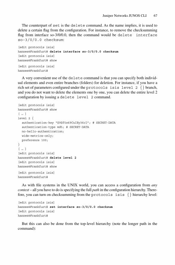
The counterpart of set is the delete command. As the name implies, it is used todelete a certain flag from the configuration. For instance, to remove the checksummingflag from interface so-3/0/0.0, then the command would be delete interface so-3/0/0.0 checksum:
[edit protocols isis]
hannes@Frankfurt# delete interface so-3/0/0.0 checksum
[edit protocols isis]
hannes@Frankfurt# show
[edit protocols isis]
hannes@Frankfurt#
A very convenient use of the delete command is that you can specify both individ-ual elements and even entire branches (folders) for deletion. For instance, if you have arich set of parameters configured under the protocols isis level 2 {} branch,and you do not want to delete the elements one by one, you can delete the entire level 2configuration by issuing a delete level 2 command.
[edit protocols isis]
hannes@Frankfurt# show
[ … ]
level 2 {
authentication-key “$9$f5z69CuIEy36cl”; # SECRET-DATA
authentication-type md5; # SECRET-DATA
no-hello-authentication;
wide-metrics-only;
preference 100;
}
[ … ]
[edit protocols isis]
hannes@Frankfurt# delete level 2
[edit protocols isis]
hannes@Frankfurt# show
[edit protocols isis]
hannes@Frankfurt#
As with file systems in the UNIX world, you can access a configuration from anycontext – all you have to do is specifying the full path in the configuration hierarchy. There-fore, you can turn on checksumming from the protocols isis {} hierarchy level:
[edit protocols isis]
hannes@Frankfurt# set interface so-3/0/0.0 checksum
[edit protocols isis]
hannes@Frankfurt#
But this can also be done from the top-level hierarchy (note the longer path in the command):
Juniper Networks JUNOS CLI 67
[edit]
hannes@Frankfurt# set protocols isis interface so-3/0/0.0 checksum
[edit]
hannes@Frankfurt#
Unlike IOS, when you enter the set and delete commands your JUNOS config-uration does not become active immediately. You can modify the configuration file asmuch and as often as you like, even deleting it fully and starting from scratch (not oftena good idea, but possible). Even complete deletion will not do any harm or disrupt yourconnectivity to the router – yet.
3.3.6 Activating a ConfigurationJUNOS changes its configuration on a transactional model. You really have two config-urations in the system:
• The active configuration• A candidate configuration
The active configuration is the one that the router currently executes. The candidateconfiguration is originally a copy of the active configuration created when you enter con-figuration mode, and it is the candidate configuration which is modified. Think of it like a document that you open and modify – nothing changes until you do a SAVE onyour wordprocessor. The analogy of the wordprocessor’s SAVE in JUNOS is the commit command. The commit command does a syntax and sanity check of the can-didate configuration and, if satisfied, copies the candidate configuration to the activeconfiguration.
[edit protocols isis]
hannes@Frankfurt# commit
commit complete
[edit protocols isis]
hannes@Frankfurt#
Do not forget to commit your changes when you start working with JUNOS. Youmight wonder why the changes did not take effect. If you are used to an IOS environ-ment, forgetting to do a commit is a frequent mistake.
In wordprocessors there is the UNDO function if you made a change and you want getback to a previous version of your document. JUNOS has a similar mechanism, which isexecuted using the rollback command. You can go back to up to nine versions of theconfiguration history by specifying a number after the rollback command.
[edit]
hannes@Frankfurt# rollback 3
[edit]
hannes@Frankfurt#
Note that the rollback command loads a historical configuration as just another can-didate configuration. It is only re-activated using the commit command again.
68 3. Introduction to the IOS and JUNOS Command Line Interface
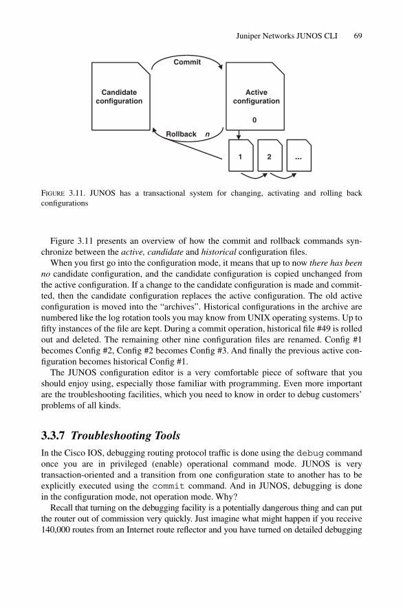
Figure 3.11 presents an overview of how the commit and rollback commands syn-chronize between the active, candidate and historical configuration files.
When you first go into the configuration mode, it means that up to now there has beenno candidate configuration, and the candidate configuration is copied unchanged fromthe active configuration. If a change to the candidate configuration is made and commit-ted, then the candidate configuration replaces the active configuration. The old activeconfiguration is moved into the “archives”. Historical configurations in the archive arenumbered like the log rotation tools you may know from UNIX operating systems. Up tofifty instances of the file are kept. During a commit operation, historical file #49 is rolledout and deleted. The remaining other nine configuration files are renamed. Config #1becomes Config #2, Config #2 becomes Config #3. And finally the previous active con-figuration becomes historical Config #1.
The JUNOS configuration editor is a very comfortable piece of software that youshould enjoy using, especially those familiar with programming. Even more importantare the troubleshooting facilities, which you need to know in order to debug customers’problems of all kinds.
3.3.7 Troubleshooting ToolsIn the Cisco IOS, debugging routing protocol traffic is done using the debug commandonce you are in privileged (enable) operational command mode. JUNOS is very transaction-oriented and a transition from one configuration state to another has to beexplicitly executed using the commit command. And in JUNOS, debugging is done in the configuration mode, not operation mode. Why?
Recall that turning on the debugging facility is a potentially dangerous thing and can putthe router out of commission very quickly. Just imagine what might happen if you receive140,000 routes from an Internet route reflector and you have turned on detailed debugging
Juniper Networks JUNOS CLI 69
Commit
Rollback n
Candidateconfiguration
Activeconfiguration
1 2 ...
0
FIGURE 3.11. JUNOS has a transactional system for changing, activating and rolling back configurations

for each and every BGP packet. Most likely the router will be busier writing the debug out-put to the local hard disk than doing something more useful, like routing packets. Therefore,many network administrators are very cautious about permitting operators to use debug.
So one of the JUNOS design choices was that debugging should be part of the config-uration file. There are actually several reasons for this:
• You can at least track who turned on a certain debug output, in case the routerbecomes unstable.
• A router’s full configuration state (including the debugging state) is stored in one file.For certain events, it may be desired to monitor the events constantly, like protocolerrors. In IOS the debugging state is lost after a reboot and so you need to manuallyturn on all the debugging states that you want to monitor after a router reboot.
• Because it is part of the configuration file, you can take advantage of the commitconfirmed command. The commit confirmed command performs an automaticrollback of the router to a safer state after a certain amount of time if the routerbecomes unstable or unreachable. (This rollback is indeed automatic: you have to makethe change explicitly permanent to countermand this action.)
Each configuration branch in the JUNOS command line hierarchy like interfaces,protocols isis, protocols bgp has a dedicated traceoptions branchwhere you can configure all the events you want to debug. But first you have to specify a file where all the debugging output is written. In JUNOS, you can’t just tell the routerto (for instance) put out all debug output directly to the console. You have to firstwrite the entire debug output into a file. However, you can make the CLI display all thenew lines in the file and display those on the console in real-time. The configuration snip-pet below shows a typical configuration for tracing (debugging) the IS-IS routingprocess:
[edit]
hannes@Frankfurt# show
[ … ]
protocols {
isis {
traceoptions {
file isis-trace size 10m;
flag error;
flag state;
flag normal;
flag lsp;
}
[ … ]
}
}
The traceoptions configuration branch always consists of two mandatory statements. The file statement specifies the filename plus arbitrary properties like pro-tection, maximum file size until it is rolled over and so on. The flag statement describes
70 3. Introduction to the IOS and JUNOS Command Line Interface

feature-specific event triggers that make the router log a line in the specified file. Eachrouting protocol has different flags: BGP has different traceoption flags to IS-IS,and so on, since routing protocols can work in fundamentally different ways. Figure 3.12list the current layout of the traceoptions for the protocols isis {} branch.
You can examine the entries in the log file using the show log �logfile-name�command:
hannes@Frankfurt> show log isis-trace
Aug 9 23:06:25 trace_on: Tracing to “/var/log/isis-trace” started
Aug 9 23:06:26 Received L2 CSN, source London, interface so- 2/1/0.0
Aug 9 23:06:26 LSP range Penssauken.00-01 to ffff.ffff.ffff.ff-ff
Aug 9 23:06:26 packet length 179
Aug 9 23:06:26 ERROR: CSN from London without authentication
Aug 9 23:06:26 Sending L2 CSN on interface so-3/0/0.0
Aug 9 23:06:26 LSP range 0000.0000.0000.00-00 to Stockholm.00-00
Aug 9 23:06:26 packet length 1478
The show log command starts displaying the file from the beginning, but it does not display any additions to the end of the file made in real-time as the display scrolls.You know the log file is displayed from the beginning because the first line contains the
Juniper Networks JUNOS CLI 71
bgp
protocols
policy-optionsisis
file
flag
interfaces chassis
traceoptionsall
csn
error
general
graceful-restart
hello
lsp
lsp-generation
normal
packets
policy
psn
route
spf
state
task
timer
FIGURE 3.12. The IS-IS traceoption flags control the verbosity of the logfile

statement that tracing has just started. However, if you want to display the most recentadditions to the end of the file in real-time, you need to start a monitor job.
hannes@Frankfurt> monitor start isis-trace
hannes@Frankfurt>
*** isis-trace ***
Aug 10 00:14:29 ERROR: IIH from London without authentication
Aug 10 00:14:29 Received L2 LSP Stockholm.00-00, interface so-3/0/0.0
Aug 10 00:14:29 from London
Aug 10 00:14:29 sequence 0x7c2, checksum 0x55bf, lifetime 65522
Aug 10 00:14:29 Updating L2 LSP Stockholm.00-00 in TED
Aug 10 00:14:29 Sending L2 LSP Stockholm.00-00 on interface fe-2/1/0.0
Aug 10 00:14:29 sequence 0x7c2, checksum 0x55bf, lifetime 65522
The router now continuously displays any new traces that are written to the file. Ifthere is a lot of routing protocol activity in the network, your console might get over-whelmed by all the logging messages and you won’t even be able to type anything to stopthe flood. To stop the output from overwhelming your console, simply type ESC Q andthen the output immediately stops;
Aug 10 00:22:01 ERROR: CSN from London without authentication
Aug 10 00:22:01 ERROR: CSN from London without authentication
Aug 10 00:22:01 ERROR: CSN from London without authentication
*** monitor and syslog output disabled, press ESC-Q to enable ***
The output is now suspended, and resumes when the ESC Q toggle is used again. Buteven with console output suspended, the monitoring job is still active, as shown by issu-ing the monitor list command:
hannes@Frankfurt> monitor list
monitor start “isis-trace” (Last changed Aug 00:23:37 20)
hannes@Frankfurt>
Finally, to stop the output to the console, issue a monitor stop isis-tracecommand. Don’t forget to unsuspend the output by pressing ESC Q again, otherwise youmay wonder when you issue your next monitor start command why there is nooutput appearing on the screen:
hannes@Frankfurt> monitor stop isis-trace
hannes@Frankfurt>
*** monitor and syslog output enabled, press ESC-Q to disable ***
The traceoptions tell you about system internal events as seen by the routing software.Sometimes the routing protocol messages seen from an interface perspective (as opposedto the router perspective) may be critical for troubleshooting purposes. JUNOS has built-inprotocol analyzer software, which is basically an enhanced version of the UNIX tcpdump
72 3. Introduction to the IOS and JUNOS Command Line Interface
utility. It is invoked using the monitor traffic interface <interface-name>command. There are a lot of additional options for the monitor traffic command. Themost important is the size option, as the tcpdump default only captures 68 bytes of apacket, typically enough to display the headers of an IP packet, but not always enoughfor a complete analysis of problems. If you need to troubleshoot routing protocols youshould specify at least the maximum size of the packet, because all of the information iscritical – not just the headers. For IS-IS this maximum size is 1492 bytes:
Tcpdump outputhannes@frankfurt> monitor traffic interface fe-0/0/1 size 1492
Listening on fe-0/0/1
00:37:30.219626 OSI, IS-IS, length: 77
L2 Lan IIH, hlen: 27, v: 1, pdu-v: 1, sys-id-len: 6 (0), max-area: 3 (0)
source-id: 1921.6807.7003, holding time: 120s, Flags: [Level 1, Level 2]
lan-id: 1921.6807.7003.02, Priority: 70, PDU length: 77
IS Neighbor(s) TLV #6, length: 6
SNPA: 00d0.b7b2.71cc
Protocols supported TLV #129, length: 2
NLPID(s): IPv4 (0xcc), IPv6 (0x8e)
IPv4 Interface address(es) TLV #132, length: 4
IPv4 interface address: 172.17.33.1
IPv6 Interface address(es) TLV #232, length: 16
IPv6 interface address: fe80::7777:69ff:fea0:8001
Area address(es) TLV #1, length: 4
Area address (length: 3): 49.0001
Restart Signaling TLV #211, length: 3
Flags [none], Remaining holding time 0s
Checksum TLV #12, length: 2
checksum: 0x5dfd (correct)
The monitor traffic command is very useful for diagnosing low-level protocolerrors. Because it provides very detailed output (as shown in the previous example), it isalso a good tool for learning about the IS-IS protocol.
3.3.8 Routing PolicyJUNOS probably has the most powerful language for controlling routing informationflow between routers. Because subsequent chapters modify the default behaviour as tohow IS-IS passes on routes to other routers, some familiarity with the JUNOS RoutingPolicy Language (RPL) is required.
In JUNOS virtually every flow of routing information, even the flow of prefixes inter-nal to the routing protocol (like the transfer of routes on an OSPF Area Border Router(ABR) from one area to another) is subject to policy processing. Policies are present simply everywhere in the routing sub-system.
In order not to reinvent the semantics of policy processing a new for each protocol, JuniperNetworks’ engineers took a different approach. Policies are stored in a protocol-neutral way
Juniper Networks JUNOS CLI 73
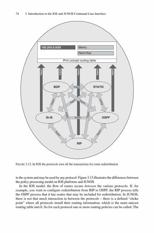
in the system and may be used by any protocol. Figure 3.13 illustrates the differences betweenthe policy processing model on IOS platforms and JUNOS.
In the IOS model, the flow of routes occurs between the various protocols. If, forexample, you want to configure redistribution from RIP to OSPF, the RIP process tellsthe OSPF process that it has routes that may be included for redistribution. In JUNOS,there is not that much interaction in between the protocols – there is a defined “chokepoint” where all protocols install their routing information, which is the main unicastrouting table inet.0. So for each protocol one or more routing policies can be called. The
74 3. Introduction to the IOS and JUNOS Command Line Interface
Imp
ort
IS-IS
BGP
OSPF
RIP
STATIC
Imp
ort
Imp
ort
Exp
ort
Export
Export Export
Export
Exp
ort
Export Expo
rt
Exp
ort
Exp
ort
Imp
ort
Imp
ort
IPv4 unicast routing table
Metric:193.203.0.0/25
Next-Hop:
FIGURE 3.13. In IOS the protocols own all the transactions for route redistribution
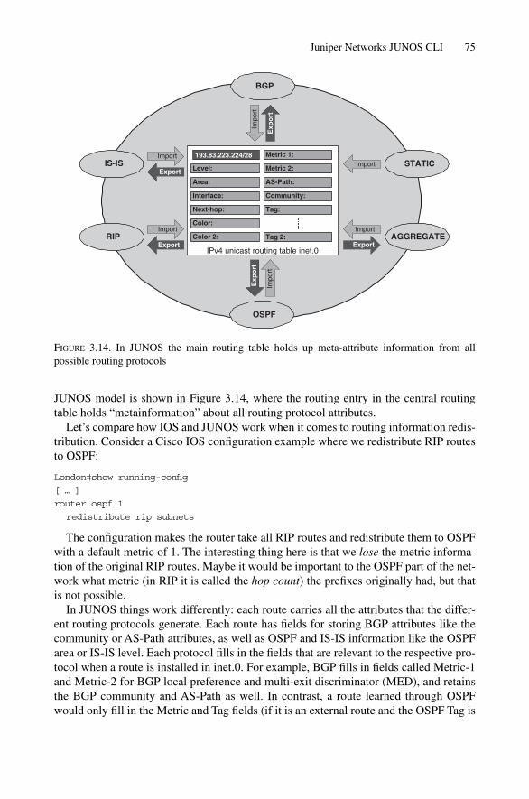
JUNOS model is shown in Figure 3.14, where the routing entry in the central routingtable holds “metainformation” about all routing protocol attributes.
Let’s compare how IOS and JUNOS work when it comes to routing information redis-tribution. Consider a Cisco IOS configuration example where we redistribute RIP routesto OSPF:
London#show running-config
[ … ]
router ospf 1
redistribute rip subnets
The configuration makes the router take all RIP routes and redistribute them to OSPFwith a default metric of 1. The interesting thing here is that we lose the metric informa-tion of the original RIP routes. Maybe it would be important to the OSPF part of the net-work what metric (in RIP it is called the hop count) the prefixes originally had, but thatis not possible.
In JUNOS things work differently: each route carries all the attributes that the differ-ent routing protocols generate. Each route has fields for storing BGP attributes like thecommunity or AS-Path attributes, as well as OSPF and IS-IS information like the OSPFarea or IS-IS level. Each protocol fills in the fields that are relevant to the respective pro-tocol when a route is installed in inet.0. For example, BGP fills in fields called Metric-1and Metric-2 for BGP local preference and multi-exit discriminator (MED), and retainsthe BGP community and AS-Path as well. In contrast, a route learned through OSPFwould only fill in the Metric and Tag fields (if it is an external route and the OSPF Tag is
Juniper Networks JUNOS CLI 75
IPv4 unicast routing table inet.0
Metric 1:
Metric 2:
AS-Path:
Community:
Tag:
193.83.223.224/28
Level:
Area:
Interface:
Next-hop:
Color:
Color 2:
IS-IS
BGP
OSPF
RIP
STATIC
AGGREGATE
Impo
rt
Exp
ort
Impo
rt
Exp
ort
Import
Export
Import
Export
Import
Export
Import
Tag 2:
FIGURE 3.14. In JUNOS the main routing table holds up meta-attribute information from all possible routing protocols

present). Because of this routing table-centric approach, you do not lose information likethe routing metric when passing on information from one protocol to the other, becausesome fields are common to all routes. Furthermore, you can even install an attribute thatdoes not exist in the source protocol. For example, you could set the AS-Path when cer-tain routes are passed on from Level-1 to Level-2 in IS-IS. (Not that this particular exam-ple is of practical relevance, it just demonstrates how powerful and flexible the JUNOSpolicy language is.)
JUNOS policies work fairly directly: all they can do is either reject or modify incom-ing routing updates, or alter or suppress outgoing routing updates. Policies can thereforebe applied on the inbound and on the outbound side of a routing protocol. In JUNOS aninbound policy is called an import policy and an outbound policy is called an exportpolicy. Figure 3.15 shows where import and export policies take effect.
The import policy controls which routes get installed in the unicast routing table. Anexport policy controls which routes are advertised to neighbouring routers. Note thatonly routes that are installed in the routing table inet.0 are exportable to other routers. A route that is known to JUNOS but not installed in inet.0 is called a hidden route inJUNOS. Many issues arise when routes can plainly be seen arriving at the router, but arenever advertised because for one reason or another they have become hidden routes andseem to have been swallowed up by the router in question.
In JUNOS, there is no interaction directly between the protocols. There is just interaction between an individual routing protocol and the routing table as shown inFigure 3.15. Each routing protocol may call one or more import and export policies. The interesting thing is that there is a common syntax for routing policies irrespectivewhich routing protocol calls the policy. For illustration, create a simple policy that selects the entire set of static routes present on a router. Routing policies consist of amatch clause and an action clause. The JUNOS keyword for the match clause is from,and the action clause is introduced by the keyword then:
policy-options {
policy-statement all-statics {
from protocol static;
then accept;
}
}
76 3. Introduction to the IOS and JUNOS Command Line Interface
Neighbors
Protocol
Forwardingtable
Neighbors
Protocol
ImportRoutes Routes
PFE
ExportRouting
table
FIGURE 3.15. JUNOS controls route advertisements via import and export policies

The above example shows a very simple policy. It creates a policy named all-statics underthe policy-options branch of the configuration hierarchy. Next, it defines the match and actionclauses. If the route’s originating protocol is “from” static, then accept that prefix. Note thatin the “then” part no detailed action is actually specified for the prefix. This is largely depend-ent on which routing protocol has called the policy, and where the policy is applied.
For example, if the policy is applied as an export policy within OSPF:
protocols {
ospf {
export all-statics;
}
}
This means that all prefixes that are installed in the inet.0 routing table and are staticroutes (these alone match the policy all-statics) will be redistributed into OSPFand announced to all OSPF neighbours.
But if the same policy is applied as an export policy within BGP:
protocols {
bgp {
group internal {
export all-statics;
neighbor 172.26.250.2;
neighbor 172.26.244.11;
[ … ]
}
}
}
This means that all the static routes present in the inet.0 table are not announced to allOSPF neighbors as in the previous example, but only to the BGP peers present in thepeer-group internal. So the ultimate result depends on where the policy is applied.
Policy processing is typically deployed for filtering BGP routes. Generally, IS-IS poli-cies are simple, one-to-three term policies, which are easily readable. To learn moreabout the JUNOS routing policy language and policy processing in general, the JuniperNetworks Book Initiative (JNBI) lists pointers to good books with more detailed elabo-ration on about policy processing.
3.3.9 Further DocumentationThe entire documentation about Juniper Networks Routers is available on the JuniperNetworks public website at http://www.juniper.net/techpubs/. Further documentation andbooks about JUNOS routing technology is posted at http://www.juniper.net/company/jnbi/.
3.4 Conclusion
Both JUNOS and IOS offer the network operator powerful user interfaces to provision,troubleshoot and change the network and router configurations. Interestingly, although
Conclusion 77

both IOS and JUNOS) user interfaces are different, there are plenty of common ele-ments, such as plain-text ASCII configuration files, two working modes (operationalmode and configuration mode), auto-completion of commands, Emacs-style keyboardsequences, and a rich debugging facility. Experience from training NOC teams has shownthat because of these common elements, an engineer that is used to one router OS can,after a short learning and introduction phase, pick up the necessary skills to adapt to a newenvironment quickly and easily.
78 3. Introduction to the IOS and JUNOS Command Line Interface
4
IS-IS Basics
79
The main challenge for people wanting to learn about IS-IS is that the specifications arescattered across multiple standardization bodies. There is no single place to look at andget a quick overview about IS-IS and how it routes the IP protocols. Meanwhile, all theextensions to the base IS-IS protocol are documented in more than 25 documents, whichmakes it difficult for novice users to get a quick overview.
This chapter provides a quick overview of IS-IS. A lot of the topics introduced in thischapter will be explained in more detail in subsequent chapters. If you just want to get aquick overview of how IS-IS works all you have to do is read this chapter.
Readers of the basic specification of IS-IS (ISO 10589) will most likely be surprised bythe constant use of OSI jargon that tries to invent an OSI counterpart for every term andacronym used in IP and the Internet. So reading this often arcane language for under-standing can be very difficult. Also, there is a lot of extra information contained in thebase specification unrelated to the protocol itself, like implementation details and evenadvice on how to code. However, most of this advice is completely outdated and it hasbecome common to ignore most of the specification text. Once you have developed anunderstanding about the jargon and what paragraphs not to read and consider, you willfind that IS-IS is a lean but powerful protocol, easy to use and even simpler to understand.
However, jargon cannot be completely avoided in IS-IS. This chapter also assumesthat readers are familiar with the basic concepts of the OSPF routing protocol and theterms used in the IP protocol family. At first, there will be translation of OSI jargon to IPterminology, but later in the book we use the OSI terms, which should become familiaras the book progresses.
4.1 IS-IS and the OSI Reference Model
IS-IS is very different than other network routing protocols because it runs natively onLayer 2 of the OSI Reference Model. What does that mean? Unlike the IP routing proto-cols like RIP, OSPF and BGP, IS-IS does not need valid interface addressing informationto transmit a message. Of course IS-IS needs some information to properly transmit rout-ing messages, but compared to other IP routing protocols, the IS-IS configuration file isfar smaller.
Running natively on Layer 2 of the OSI Reference Model has another importantaspect, which is suitability for routing multiple protocols. In fact IS-IS is totally agnosticabout what kind of prefixes it transports in its message. Figure 4.1 shows the position ofIS-IS in the networking stack. Here, IS-IS messages are directly encapsulated for an

802.3 Ethernet. And in the message is reachability information from the various networklayer protocols such as IPv4, IPv6 and even IPX. Netware uses a clone of IS-IS calledNetware Link State Routing Protocol (NLSRP), which shares most of the message typeswith IS-IS, and it is used for conveying Netware’s IPX reachability information. Figure 4.1also shows, somewhat surprisingly for those used to IP, that ISO’s Layer 3 protocol, CLNP,is dependent on IS-IS and not the other way around as it would be with IP and OSPF.
This misconception is common, as we have learned over and over again when givingIS-IS training classes. Most students think that running CLNP is the prerequisite for run-ning IS-IS. This belief is reinforced if the students first learn about IS-IS on Cisco’s IOS.For code legacy reasons, you have to enable CLNS routing first before you can run IS-ISon IOS platforms. Even for the majority of IOS show commands there is still only theshow clns … syntax instead of show isis …. Therefore most people think that IS-ISruns over CLNP, even though the contrary is the case. IS-IS is an independent protocoland CLNP is just one of the many protocol address families it can transport.
IS-IS only understands two interface types: broadcast and point-to-point (p2p) media.The most common example of broadcast media is of course the family of Ethernet speeds(10, 100, 1000, 10,000 Mbps). But there are also older technologies like Token Ring, andFDDI. In recent years there has been increased demand for Resilient Packet Ring (RPR)technology, which is mostly an FDDI knockoff, but augmented with SONET/SDH head-ers, which makes the frames transportable using SONET/SDH Time Division Multiplexing(TDM) equipment. Resilient Packet Rings appear to IS-IS as broadcast media using theusual LAN 48-bit IEEE MAC addresses. Of all these media types, Ethernet is the mostcommonplace by far and is also the only broadcast media type that will be referencedthroughout the book. Figure 4.2 shows how a native IS-IS message is encapsulated inEthernet frames. All IS-IS messages are sent to one of the two well-known multicastMAC addresses 0180:c200:0014 or 0180:c200:0014. On broadcast media such as Ethernetthere are no IS-IS unicast messages. IS-IS wants to make sure that every router con-nected to the LAN hears all of its messages. The source MAC address is typically theburned-in-address (BIA) of the sending Ethernet port. Next is the length field, which tellsthe receiver how long the entire Ethernet frame will be. The next two bytes indicate thedestination service attachment point (DSAP) and source service attachment point(SSAP). Each major networking protocol has an SAP code point assigned. The twoSAPs indicate which parts of the system talk to each other. A DSAP of 0xFE and a SSAPof 0xFE means that an OSI protocol on the sender side wants to talk to an OSI protocolon the receiver side (oddly, the DSAP and SSAP don’t have to match, but most protocols
80 4. IS-IS Basics
IS-IS common header
OSI Reference Model Layer 2
IP IPXIPv6CLNP
IEEE 802.3
Physical Layer OSI Reference Model Layer 1
FIGURE 4.1. IS-IS is a true multiprotocol IGP as it runs native on Layer-2

only understand other versions of themselves). The last byte before the common IS-ISheader is the control byte which tells the receiver if the sender desires flow-control at theEthernet level. IS-IS does not do flow-control at the MAC level, and turns it off using thecode point value of 3.
For Ethernet there are in general three different methods of encapsulating higher layer information (packets) inside Ethernet frames. The encapsulation method shown inFigure 4.2 is called 802.3 or, in Cisco Systems-IOS-speak, SAP encapsulation. There isalso the Ethernet II encapsulation also known as DIX or ARPA encapsulation, whichreplaces the length field of the 802.3 encapsulation format with a 16-bit type code.Assigning all type codes with values greater than 1500 (the limit for the length field)avoids collisions between code points and valid frame lengths, which must be less than1518 bytes altogether. The final encapsulation method is called sub-network access proto-col (SNAP), and is an extension of the IEEE 802.3 encapsulation. The DSAP and SSAPare set to 0xAA (the “SNAP SAP”) and this indicates that another 5-byte header follows,which gives the protocols inside more room for type information and eases the allocationof code points for vendor-proprietary protocols. This is achieved by prepending the 3-byte organizational unit identifier (OUI) that each Ethernet vendor has been assignedbefore the 2-byte protocol code point (which is actually the DIX Ethernet type field thatthe length field replaced!).
Interestingly, IS-IS never used any other encapsulation than 802.3. So although thereare OSI code points for the two other encapsulation methods (Ethernet II and SNAP)they have never been widely used for IS-IS. Most IS-IS implementations did not evenaccept IS-IS messages with a non-IEEE 802.3 encapsulation style. Today, IEEE 802.3encapsulation is the only possible Ethernet encapsulation for IS-IS and the two others areconsidered to be “illegal”.
IS-IS and the OSI Reference Model 81
Destination MAC Address 0180:c200:0014or 0180:c200:0015
Bytes
6
6
2
1
1
1
min.: 27max.: Link MTU-21
Source MAC Address
IEEE 802.3 Length field
IEEE 802.3 DSAP
IEEE 802.3 SSAP
IEEE 802.3 Control
IS-IS common header & TLVs
FCS
0xFE
0xFE
0x03
4
FIGURE 4.2. IS-IS messages are transported over Ethernet using IEEE 820.3 (802.2 LLC) encap-sulation only
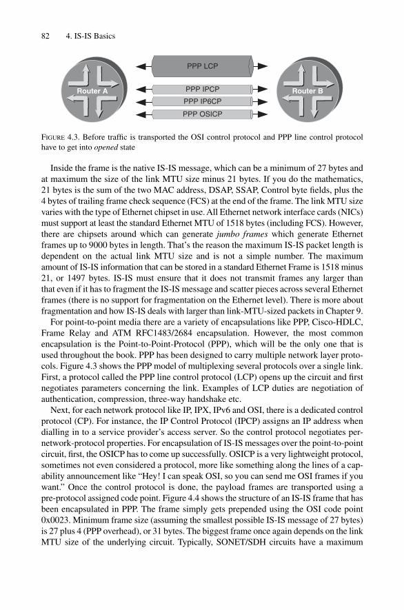
Inside the frame is the native IS-IS message, which can be a minimum of 27 bytes andat maximum the size of the link MTU size minus 21 bytes. If you do the mathematics,21 bytes is the sum of the two MAC address, DSAP, SSAP, Control byte fields, plus the4 bytes of trailing frame check sequence (FCS) at the end of the frame. The link MTU sizevaries with the type of Ethernet chipset in use. All Ethernet network interface cards (NICs)must support at least the standard Ethernet MTU of 1518 bytes (including FCS). However,there are chipsets around which can generate jumbo frames which generate Ethernetframes up to 9000 bytes in length. That’s the reason the maximum IS-IS packet length isdependent on the actual link MTU size and is not a simple number. The maximumamount of IS-IS information that can be stored in a standard Ethernet Frame is 1518 minus21, or 1497 bytes. IS-IS must ensure that it does not transmit frames any larger than that even if it has to fragment the IS-IS message and scatter pieces across several Ethernetframes (there is no support for fragmentation on the Ethernet level). There is more aboutfragmentation and how IS-IS deals with larger than link-MTU-sized packets in Chapter 9.
For point-to-point media there are a variety of encapsulations like PPP, Cisco-HDLC,Frame Relay and ATM RFC1483/2684 encapsulation. However, the most commonencapsulation is the Point-to-Point-Protocol (PPP), which will be the only one that isused throughout the book. PPP has been designed to carry multiple network layer proto-cols. Figure 4.3 shows the PPP model of multiplexing several protocols over a single link.First, a protocol called the PPP line control protocol (LCP) opens up the circuit and firstnegotiates parameters concerning the link. Examples of LCP duties are negotiation ofauthentication, compression, three-way handshake etc.
Next, for each network protocol like IP, IPX, IPv6 and OSI, there is a dedicated controlprotocol (CP). For instance, the IP Control Protocol (IPCP) assigns an IP address whendialling in to a service provider’s access server. So the control protocol negotiates per-network-protocol properties. For encapsulation of IS-IS messages over the point-to-pointcircuit, first, the OSICP has to come up successfully. OSICP is a very lightweight protocol,sometimes not even considered a protocol, more like something along the lines of a cap-ability announcement like “Hey! I can speak OSI, so you can send me OSI frames if youwant.” Once the control protocol is done, the payload frames are transported using a pre-protocol assigned code point. Figure 4.4 shows the structure of an IS-IS frame that hasbeen encapsulated in PPP. The frame simply gets prepended using the OSI code point0x0023. Minimum frame size (assuming the smallest possible IS-IS message of 27 bytes)is 27 plus 4 (PPP overhead), or 31 bytes. The biggest frame once again depends on the linkMTU size of the underlying circuit. Typically, SONET/SDH circuits have a maximum
82 4. IS-IS Basics
PPP LCP
PPP IPCP
PPP IP6CP
PPP OSICP
Router A Router B
FIGURE 4.3. Before traffic is transported the OSI control protocol and PPP line control protocolhave to get into opened state

transmission unit of 4474 bytes. By subtracting the PPP overhead (4 bytes) from the 4474bytes, this results in 4470 being the maximum MTU size on most point-to-point circuits.
IS-IS skipped all the hassle of complicated varieties of encapsulation and interfacemodels by specifying very clearly in the specification how the format of the final framelooks. This clearly helped interoperable implementations to exist right from the beginning.
4.2 Areas
OSI structures its network topology in a distinctive way. IS-IS is much more flexiblewhen it comes down to migrating parts of the network to another routing protocol orgrooming existing ones. The tool to make that happen is called an area.
In the infancy of link-state protocols, the whole network consisted of a single set ofrouters that all shared a common database to compute the best paths through the network.At this time almost everybody working in standardization bodies seemed to be concernedabout the nature of the SPF algorithm and doubted the scaling abilities of link-state routingprotocols in general. In light of the exponential nature of the SPF algorithm, where theCPU demand seemed to grow infinite, the IS-IS protocol developers made an interest-ing move.
The idea was to structure a large network in smaller parts called areas. The topologi-cal horizon of the IS-IS routers becomes smaller to keep the CPU less busy during theroute calculation process. But if a bigger network is split into smaller networks, then aset of disjoint sub-networks results. In order to connect these islands there need to berouters that route traffic between the areas. Even if the topological horizon and hence thecomputational complexity of the SPF run has been reduced, the network still has to retainall available reachability information and the routers at the area borders inject that reach-ability information into each other’s areas. Figure 4.5 shows how this is done. The BigIS-IS network 4711 is split into two areas: Area 47 and Area 11. The computational com-plexity has been halved; however, in order to ensure full connectivity the router betweenArea 47 and Area 11, Router A, summarizes and injects all the reachable prefixes fromArea 47 to Area 11, and Router B does the reverse. The IP prefixes in this exampleassume the reader is familiar with IP addressing and style. However, the transported pre-fixes are not restricted to just IP, they could be from any address family. Router A andRouter B summarize their local prefixes and advertise them into the other areas. Router Asends a summary route 172.16/16 representing the local 172.16.X/24 prefixes (including
Areas 83
Bytes
2
2
min.: 31max.: Link MTU-4
PPP Header
PPP OSI Protocol
IS-IS common header & TLVs
0xFF03
0x0023
FIGURE 4.4. IS-IS over PPP

its own) towards Area 11 and Router B sends a summary route 172.17/16, resulting fromall the local 172.17.X/24 prefixes in Area 11, to Area 47.
The effect is remarkable – today, 1000–2000 routers in a single area are said to repre-sent the upper boundary of IS-IS. With support of areas the network can grow to arbitrarysize – today the biggest multi-area networks have about 12,000–15,000 routers. Theauthors do not endorse these optimistic area numbers, since a lot, is dependent on otherfactors than just the raw number of routers. But the above example should make it clearthat by splitting up a large network into several smaller areas, the result is a network thatis much more scalable than with a single-area approach.
Note that in Figure 4.5 Router A and Router B are members of their assigned areas andare not part of both areas. To those familiar with OSPF, this may seem odd at first, but IS-ISmakes a distinction between area boundaries and the routing hierarchy levels that result.Decoupling area boundaries from routing hierarchy levels allows greater flexibility formigrating, joining, or splitting areas. The tool in IS-IS for creating routing hierarchies iscalled a level.
84 4. IS-IS Basics
Area 11Area 47
Area 4711
172.16.4/24Router A Router B
172.17.7/24
172.17.8/24
172.17.9/24
172.16.1/24
172.16.2/24
172.16.3/24
172.16.1/24
172.16.2/24
172.16.3/24
172.17.7/24
172.17.8/24
172.17.9/24
172.16.4/24 172.17.6/24
172.16/16 172.17/16
FIGURE 4.5. For a working hierarchical routing, the border routers need to summarize the reacha-bility information of their areas and inject it to the other areas
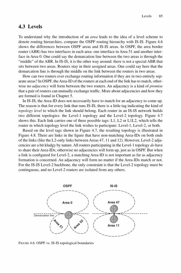
4.3 Levels
To understand why the introduction of an area leads to the idea of a level scheme todenote routing hierarchies, compare the OSPF routing hierarchy with IS-IS. Figure 4.6shows the differences between OSPF areas and IS-IS areas. In OSPF, the area borderrouter (ABR) has two interfaces in each area: one interface in Area 51 and another inter-face in Area 0. One could say the demarcation line between the two areas is through the“middle” of the ABR. In IS-IS, it is the other way around: there is not a special ABR thatsits between two areas. Routers stay in their assigned areas. One could say here that thedemarcation line is through the middle on the link between the routers in two areas.
How can two routers ever exchange routing information if they are in two entirely sep-arate areas? In OSPF, the Area-ID of the routers at each end of the link has to match, other-wise no adjacency will form between the two routers. An adjacency is a kind of promisethat a pair of routers can mutually exchange traffic. More about adjacencies and how theyare formed is found in Chapter 5.
In IS-IS, the Area-ID does not necessarily have to match for an adjacency to come up.The reason is that for every link that runs IS-IS, there is a little tag indicating the kind oftopology level to which the link should belong. Each router in an IS-IS network buildstwo different topologies: the Level-1 topology and the Level-2 topology. Figure 4.7shows this. Each link carries one of three possible tags: L1, L2 or L1L2, which tells therouter in which topology level the link wishes to participate: Level-1, Level-2, or both.
Based on the level tags shown in Figure 4.7, the resulting topology is illustrated inFigure 4.8. There are links in the figure that have non-matching Area-IDs on both endsof the links (like the L2-only links between Areas 47, 11 and 12). However, Level-2 adja-cencies are a bit kludgy by nature. All routers participating in the Level-1 topology do haveto share their Area-IDs; otherwise no adjacencies will form up, just as in OSPF. But whena link is configured for Level-2, a matching Area-ID is not important as far as adjacencyformation is concerned. An adjacency will form no matter if the Area-IDs match or not.For the IS-IS Level-2 backbone, the only constraint is that the Level-2 topology must becontinguous, and no Level-2 routers are isolated from any others.
Levels 85
Area 51
Area 0
Demarcation line
Area 11
Area 47
Area
52
OSPF IS-IS
FIGURE 4.6. OSPF vs. IS-IS topological boundaries
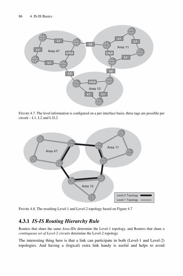
4.3.1 IS-IS Routing Hierarchy RuleRouters that share the same Area-IDs determine the Level-1 topology, and Routers that share acontinguous set of Level-2 circuits determine the Level-2 topology
The interesting thing here is that a link can participate in both (Level-1 and Level-2)topologies. And having a (logical) extra link handy is useful and helps to avoid
86 4. IS-IS Basics
Area 11
Area 12
Area 47L1L2
L2
L1L2
L2
L1L2
L2
L1L1
L1
L1
L1
L1
L1L1
FIGURE 4.7. The level information is configured on a per interface basis; three tags are possible percircuit – L1, L2 and L1L2
Area 11
Area 12
Area 47
Level 2 Topology
Level 1 Topology
FIGURE 4.8. The resulting Level-1 and Level-2 topology based on Figure 4.7

sub-optimal routing. Figure 4.9 shows how OSPF routes inter-area versus intra-area traf-fic. Consider traffic flowing between the two leaf-sites S (source) and D (destination).Traffic arrives at the ABR and OSPF has two routes available to route that traffic – onedirect route (the intra-area) over two low-speed T1 circuits, and another route that leadsover the backbone (the inter-area route), which has one T1 segment less and plenty ofbandwidth available, as there is a Gigabit Ethernet segment in the path. But just like anyother hierarchical routing protocol, OSPF prefers to get inter-area backbone traffic tointra-area routes as soon as possible. So ultimately the traffic takes the path indicated bythe gray arrow.
Common practice to fix that problem in OSPF is to spend money to put another linkbetween the two Area Border Routers as indicated by the thick black dotted line. Thislink is configured to run in Area 52 and produces a lot of new, low-cost paths to avoid theslower T1 hopping of traffic. In IS-IS the problem is solved similarly, except that you donot have to expense two Gigabit Ethernet router ports! Figure 4.10 shows how IS-ISavoids this expense by the level between the routers that were OSPF Area Border RoutersIS-IS L1L2 capable. Now, over the same physical circuit (the Gigabit Ethernet Segment),IS-IS forms adjacencies on a per-level basis, and both Level-1 and Level-2 adjacenciesform on the same link. Therefore, the Gigabit Ethernet link is an integral part of Area 52and preferred when traffic travels from S to D.
4.3.2 Route Leaking Between LevelsEvery routing protocol passes a certain amount of routing information up the routinghierarchy, and other routing information is passed down the routing hierarchy. There is abi-directional flow of routing information known as route leaking. To better understandhow IS-IS leaks routes between levels, first look at how OSPF passes routing informationup and down. Figure 4.11 shows how OSPF leaks information between levels. For sim-plicity reasons, this example uses the default behaviour of how OSPF leaks routes. Of
Levels 87
Area 52
Area 0(Backbone)
1000 Mbps
1.544 Mbps
1.54
4 M
bps
1.54
4 M
bps
Area 51
1.544 Mbps
D
S
FIGURE 4.9. The OSPF constraint that one interface can only be in one area can cause sub-optimalrouting

88 4. IS-IS Basics
Area 52
1000 Mbps
1.544 Mbps
1.54
4 M
bps
1.54
4 M
bps
S
D
Level 2 Topology
Level 1 Topology1.
544
Mbp
s
FIGURE 4.10. IS-IS can share a link between Level-1 and Level-2 topologies – this fixes the sub-optimal routing problem in a cost-effective way
rout
es to
BB
Area 51 Area 52
Area 53
Area 0
routes to BB
routes to BB
rout
es fr
om B
B
routes from BB
routes from BB
FIGURE 4.11. OSPF short-circuits reachability information between all areas, which can be a scaling harm

course, there are lots of other ways to leak OSPF routes between areas, such as Totally-Stubby-Areas, Stub-Areas and Not-So-Stubby-Areas (NSSA), but this is just an example.In our example network, there are three areas interconnected by three OSPF Area BorderRouters, and the backbone is OSPF Area 0. In OSPF, each ABR takes the routes it cal-culated from the non-zero areas and redistributes it automatically to the backbone. Thegray arrow indicates this step. The backbone in turn redistributes all the routes it haslearned from all of the areas and feeds back that information to each as well. Ultimately,each router gets all the routing information. This is one of the scaling issues of OSPF: thefact that each area sees all the routes. This has resulted in all the add-on OSPF concepts(Totally-Stubby-Areas, NSSA) to fix that behaviour.
IS-IS is very different in this respect. Similarly to OSPF, it leaks information from Level-1 to Level-2. However, IS-IS does not leak down any information from Level-2 toLevel-1. Figure 4.12 shows how IS-IS deals with route distribution in a hierarchical routingenvironment. IS-IS sets a bit in its routing messages for the respective areas. This particu-lar bit is called the Attach bit or, for short, the ATT bit. Any router that is part of the Level-2topology (that is, the router has at least one adjacency on a Level-2 circuit in the “Up” state)must set the ATT bit on messages. The routers in the areas simply calculate their shortest
Levels 89
Area 11 Area 12
Area 13
routes to BB
AT
T
ATT
ATT routes to BB
rout
es to
BB
FIGURE 4.12. IS-IS does not distribute all reachability information down to the Level-2. Routes just flow up and never down the hierarchy, which is a good scaling property

path to the closest router that has sent messages with the ATT bit set and installs a default0/0 route in its routing/forwarding table pointing to the closest L1L2 router. This is exactlythe behaviour of Totally-Stubby-Areas in OSPF, and no wonder, since both address thesame issue. However, in IS-IS you can do a few things that cannot be achieved usingTotally-Stubby-Areas in OSPF, like injecting external routing information into the cloud.Luckily, OSPF NSSAs fix that problem. So to quickly explain to those familiar with OSPFthe way that IS-IS leaks its routing information, it is safe to say “Almost like NSSA!”.There will be more details on how exactly route leakage works in IS-IS, using a lot ofexamples and router configurations, in Chapter 12 “IP Reachability Information”.
Assigning links arbitrarily to the two topologies proved to be a very flexible designtool that today no network designer would be without. It would seem, then, that address-ing and address allocation is not an important aspect of an IS-IS network design, but donot be misled. A careful area design is what prepares an IS-IS network for all kinds ofmigration and expansion. A clear understanding of the differences between area address-ing and the routing hierarchy is at first a bit difficult to understand in IS-IS. However,there is also a lot of operational flexibility that results from this differentiation, particu-larly when it comes to migrating areas.
4.4 Area Migration Scenarios
In contrast to OSPF, an IS-IS router can be in multiple areas at the same time. Havingsupport for more than one area is mandatory to migrate area addresses. If a routing proto-col has only support for one area at a time, then the change of area addresses becomeshighly disruptive. Just think about the disruptive nature of migrating an OSPF area,which is a routing protocol that supports just one area address per adjacency. You cannotmigrate an OSPF network’s area during normal business hours: you need to allocate amaintenance window for it.
IS-IS is friendlier to migrations in this respect. In the IS-IS Hello messages there isroom enough to support more than one Area-ID. In each IS-IS message, the first 8 bytes arecalled the common header. Figure 4.13 shows the common header that is prepended toall IS-IS messages. The last byte in the common header is a pre-indicator of the maximumamount of Area-IDs the system is going to advertise. However, most IS-IS implementa-tions (including IOS and JUNOS) do not support more than 3 areas in these messages (of course, the total number of areas in the network is another matter).
This is no real limitation in practice, as support for three areas for one router at thesame time supports all the area migration scenarios of interest, which are:
• Merging two areas into a single area• Splitting one area into two areas• Renumbering two areas to a new area
How does IS-IS treat a pair of routers that have different Area-IDs? And how is adja-cency formation affected by different Area-IDs? IS-IS does not require that the Area-IDmatches before a Level-1 adjacency comes up – support for multiple Area-IDs has beenmentioned already. So there is no single Area-ID that has to match. But first IS-IS collects
90 4. IS-IS Basics

the advertised Area-IDs from both sides of the link. Then IS-IS looks to see if there is anArea-ID in common. If there is at least one matching area address then the Level-1 adja-cency goes into the Up state. Figure 4.14 shows four routers (A, B, C, D), and not all ofthem are in the same area. No problem! As long as there is at least a single pair of routersthat is present in both areas (Router A and B), the adjacency between A and B goes into theUp state and the routes of all four routers get distributed and finally received by all therouters in the Level-1 network.
Area Migration Scenarios 91
Intra-domain Routing Protocol Discriminator
Header Length Indicator
Version/Protocol ID Extension
0x83
Bytes
1
1
1
1
1
1
1
1
1
ID Length
PDU TypeR0
R0
R0
PDU Version
Reserved
Maximum Area Addresses
6 (0)
1
3 (0)
0
PDU specific fields 17–33
TLV section 0–1467
FIGURE 4.13. The IS-IS common header consists of 8 bytes that are contained in every IS-IS message.The last byte consists of the number of areas that the router supports
Area 11 Area 12
A B
DC
Level 2 TopologyLevel 1 Topology
FIGURE 4.14. In an IS-IS Level-1 network there can even be multiple area addresses as long thereis at least a pair of routers present in both areas

Before going into the details of the migration scenarios, it will be helpful to show someconfiguration snippets from JUNOS and IOS and also show for the first time the ISONetwork Entity Titles (NETs), which may be new. All you really need to know is that thefirst few bytes of the NET specify the Area-ID, but the exact number of bytes varies. Thereason why there is no fixed mapping of the Area-ID into the NET is because the NETs arevariable in size and, depending on the address format, the Area-ID size also varies. There isa more detailed presentation of NETs later in this chapter, in the “OSI Addressing” section.
The most common migration scenarios will demonstrate how flexible IS-IS interpretsthe term area.
4.4.1 Merging AreasFigure 4.15 shows two disjoint Areas 11 and 12, which are ultimately to be joined into acommon Area 11. The figure shows the network before and after the migration. Next tothe router there is the corresponding configuration snippet – a snippet far from beingcomplete – just the IS-IS-related configuration commands are presented. This migrationis rather simple. First, there are two pairs of routers, each pair is disjoint to the other pair.As this is a multivendor book, there are configuration snippets from the two dominant(IOS and JUNOS) IS-IS implementations in the Internet included.
The migration does not happen atomically (in a single step). Several transient configu-rations have to be followed for a smooth transition. To be non-disruptive, first an additionalNET is configured on Router A. For a short period of time Router A is configured with twoNETs: 11.aaaa.aaaa.aaaa.00 and 12.aaaa.aaaa.aaaa.00. In the next step, add the commonAreas NETs to Router C as well. Now all the routers have Area-ID 12 configured. Now wecan clean up existing configurations and remove the Area 11 NET off Routers A and C. Sothe areas have been merged into a common area in a non-disruptive way.
4.4.2 Splitting AreasSplitting areas is done in a similar fashion to merging areas, just (in a sense) in the oppos-ite direction. Figure 4.16 gives an example of how to break an existing area into twosmaller areas. First, the pair of routers has to be determined that will have both Area-IDs.In this example, Routers A and B are the routers which have both Area-IDs configured.The migration “style” here is again from the centre to the edge. So, first, the Area 11 NETsare configured on the Routers B, A, and D. Finally, Area 12 is removed from Router C.Again, the whole area can be configured in a non-disruptive fashion as long as the con-figuration order is maintained.
4.4.3 Renumbering AreasRenumbering areas means that one or more areas get a new Area-ID. This examplechange of Area-IDs does not just affect some routers in the network, but all routers in thenetwork. Nevertheless, if the correct order is followed, even this complex migration canbe accomplished in a simple and non-disruptive fashion.
92 4. IS-IS Basics
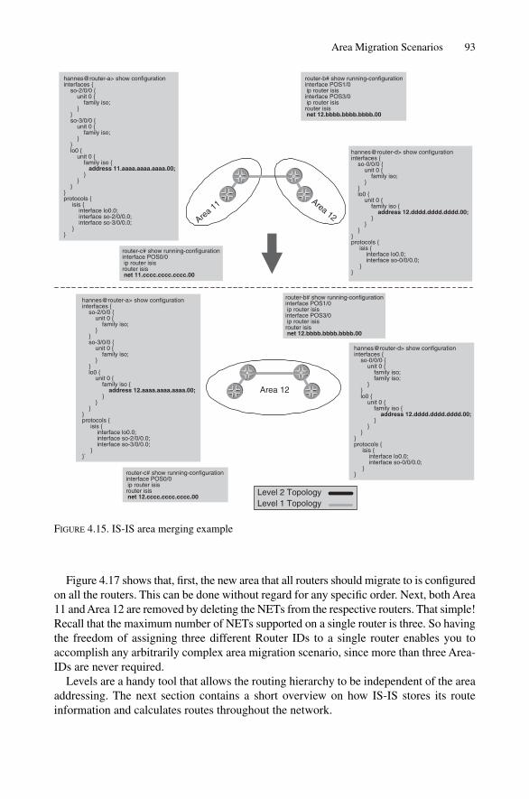
Figure 4.17 shows that, first, the new area that all routers should migrate to is configuredon all the routers. This can be done without regard for any specific order. Next, both Area11 and Area 12 are removed by deleting the NETs from the respective routers. That simple!Recall that the maximum number of NETs supported on a single router is three. So havingthe freedom of assigning three different Router IDs to a single router enables you toaccomplish any arbitrarily complex area migration scenario, since more than three Area-IDs are never required.
Levels are a handy tool that allows the routing hierarchy to be independent of the areaaddressing. The next section contains a short overview on how IS-IS stores its routeinformation and calculates routes throughout the network.
Area Migration Scenarios 93
Area 11 Area 12
router-c# show running-configurationinterface POS0/0 ip router isisrouter isis net 11.cccc.cccc.cccc.00
hannes@router-a> show configurationinterfaces { so-2/0/0 { unit 0 { family iso; } } so-3/0/0 { unit 0 { family iso; } } lo0 { unit 0 { family iso { address 11.aaaa.aaaa.aaaa.00; } } }}protocols { isis { interface lo0.0; interface so-2/0/0.0; interface so-3/0/0.0; }}
Area 12
router-b# show running-configurationinterface POS1/0 ip router isisinterface POS3/0 ip router isisrouter isis net 12.bbbb.bbbb.bbbb.00
router-c# show running-configurationinterface POS0/0 ip router isisrouter isis net 12.cccc.cccc.cccc.00
hannes@router-a> show configurationinterfaces { so-2/0/0 { unit 0 { family iso; } } so-3/0/0 { unit 0 { family iso; } } lo0 { unit 0 { family iso { address 12.aaaa.aaaa.aaaa.00; } } }}protocols { isis { interface lo0.0; interface so-2/0/0.0; interface so-3/0/0.0; }}`
hannes@router-d> show configurationinterfaces { so-0/0/0 { unit 0 { family iso; family iso; } } lo0 { unit 0 { family iso { address 12.dddd.dddd.dddd.00; } } }}protocols { isis { interface lo0.0; interface so-0/0/0.0; }}
A B
DC
Level 2 TopologyLevel 1 Topology
A B
DC
router-b# show running-configurationinterface POS1/0 ip router isisinterface POS3/0 ip router isisrouter isis net 12.bbbb.bbbb.bbbb.00
hannes@router-d> show configurationinterfaces { so-0/0/0 { unit 0 { family iso; } } lo0 { unit 0 { family iso { address 12.dddd.dddd.dddd.00; } } }}protocols { isis { interface lo0.0; interface so-0/0/0.0; }}
FIGURE 4.15. IS-IS area merging example

4.5 Local SPF Computation
IS-IS follows a simple principle called distributed databases and local computation.Distributed databases means that all routers agree how many routers are in the networkand how they are connected with each other. Local computation means that each routerreceivers the same topological information and prefixes unaltered. So, for example, norouter is allowed to change the originator’s information.
IS-IS stores all information about other routers and links in the link-state database(LSDB). There is a dedicated LSDB per Level: one for the Level-1 and one for the Level-2.
94 4. IS-IS Basics
Area 12
router-b# show running-configurationinterface POS1/0 ip router isisinterface POS3/0 ip router isisrouter isis net 12.bbbb.bbbb.bbbb.00
router-c# show running-configurationinterface POS0/0 ip router isisrouter isis net 12.cccc.cccc.cccc.00
hannes@router-a> show configurationinterfaces { so-2/0/0 { unit 0 { family iso; } } so-3/0/0 { unit 0 { family iso; } } lo0 { unit 0 { family iso { address 12.aaaa.aaaa.aaaa.00; } } }}protocols { isis { interface lo0.0; interface so-2/0/0.0; interface so-3/0/0.0; }}
hannes@router-d> show configurationinterfaces { so-0/0/0 { unit 0 { family iso; } } lo0 { unit 0 { family iso { address 12.dddd.dddd.dddd.00; } } }}protocols { isis { interface lo0.0; interface so-0/0/0.0; }}
Area 11 Area 12
router-b# show running-configurationinterface POS1/0 ip router isisinterface POS3/0 ip router isisrouter isis net 12.bbbb.bbbb.bbbb.00 net 11.bbbb.bbbb.bbbb.00
router-c# show running-configurationinterface POS0/0 ip router isisrouter isis net 11.cccc.cccc.cccc.00
hannes@router-a> show configurationinterfaces { so-2/0/0 { unit 0 { family iso { address 12.aaaa.aaaa.aaaa.00; } } } so-3/0/0 { unit 0 { family iso; } } lo0 { unit 0 { family iso { address 11.aaaa.aaaa.aaaa.00; } } }}protocols { isis { interface lo0.0; interface so-2/0/0.0; interface so-3/0/0.0; }}
hannes@router-d> show configurationinterfaces { so-0/0/0 { unit 0 { family iso; } } lo0 { unit 0 { family iso { address 12.dddd.dddd.dddd.00 } } }}protocols { isis { interface lo0.0; interface so-0/0/0.0; }}
Level 2 Topology
Level 1 Topology
A B
DC
A B
DC
FIGURE 4.16. Area splitting example

You can display the contents of the database using the show isis database com-mand on both IOS and JUNOS.
IOS commandThe show isis database command shows first the Level-1 and next the Level-2database.
Local SPF Computation 95
Area 11 Area 12
router-b# show running-configurationinterface POS1/0 ip router isisinterface POS3/0 ip router isiser isisrout net 12.bbbb.bbbb.bbbb.00 net 11.bbbb.bbbb.bbbb.00
router-c# show running-configurationinterface POS0/0 ip router isisrouter isis net 11.cccc.cccc.cccc.00
hannes@router-a> show configurationinterfaces { so-2/0/0 { unit 0 { family iso { address 12.aaaa.aaaa.aaaa.00; } } } so-3/0/0 { unit 0 { family iso; } } lo0 { unit 0 { family iso { address 11.aaaa.aaaa.aaaa.00; } } }}protocols { isis { interface lo0.0; interface so-2/0/0.0; interface so-3/0/0.0; }}
hannes@router-d> show configurationinterfaces { so-0/0/0 { unit 0 { family iso; } } lo0 { unit 0 { family iso { address 12.dddd.dddd.dddd.00; } } }}protocols { isis { interface lo0.0; interface so-0/0/0.0; interface so-0/0/0.0; }}
Area 13
router-b# show running-configurationinterface POS1/0 ip router isisinterface POS3/0 ip router isisrouter isis net 13.bbbb.bbbb.bbbb.00
router-c# show running-configurationinterface POS0/0 ip router isisrouter isis net 13.cccc.cccc.cccc.00
hannes@router-a> show configurationinterfaces { so-2/0/0 { unit 0 { family iso; } } so-3/0/0 { unit 0 { family iso; } } lo0 { unit 0 { family iso { address 13.aaaa.aaaa.aaaa.00; } } }}protocols { isis { interface lo0.0; interface so-2/0/0.0; interface so-3/0/0.0; }}
hannes@router-d> show configurationinterfaces { so-0/0/0 { unit 0 { family iso; } } lo0 { unit 0 { family iso { address 13.dddd.dddd.dddd.00; } } }}protocols { isis { interface lo0.0; interface so-0/0/0.0; }}
Level 2 TopologyLevel 1 Topology
A B
DC
A B
DC
FIGURE 4.17. Area renumbering example – during configuration the worst case is that 3 areas arenecessary, which is the reason that 3 areas is the default that every vendor does support
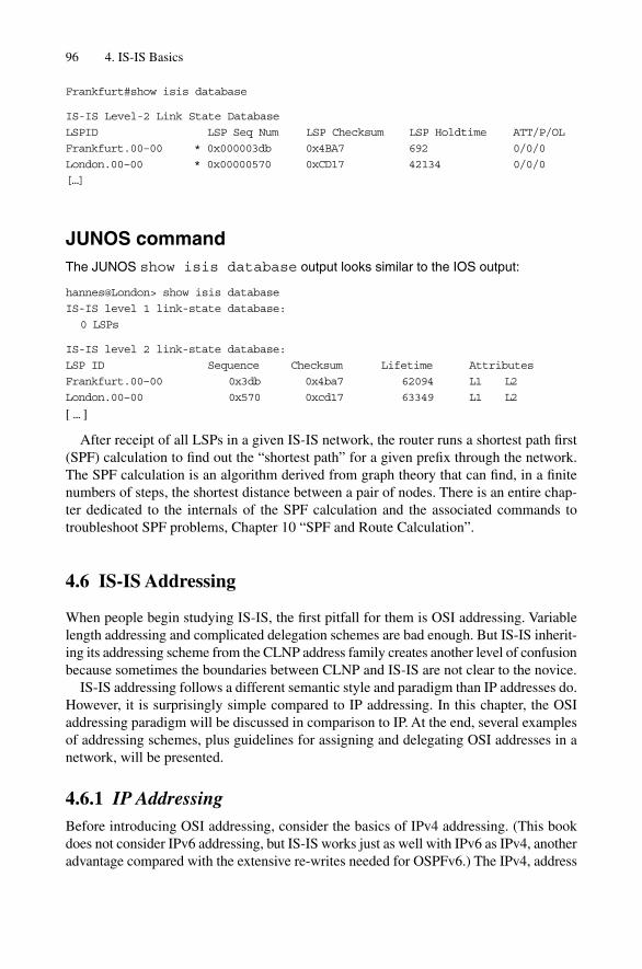
Frankfurt#show isis database
IS-IS Level-2 Link State Database
LSPID LSP Seq Num LSP Checksum LSP Holdtime ATT/P/OL
Frankfurt.00–00 * 0x000003db 0x4BA7 692 0/0/0
London.00–00 * 0x00000570 0xCD17 42134 0/0/0
[…]
JUNOS commandThe JUNOS show isis database output looks similar to the IOS output:
hannes@London> show isis database
IS-IS level 1 link-state database:
0 LSPs
IS-IS level 2 link-state database:
LSP ID Sequence Checksum Lifetime Attributes
Frankfurt.00–00 0x3db 0x4ba7 62094 L1 L2
London.00–00 0x570 0xcd17 63349 L1 L2
[ … ]
After receipt of all LSPs in a given IS-IS network, the router runs a shortest path first(SPF) calculation to find out the “shortest path” for a given prefix through the network.The SPF calculation is an algorithm derived from graph theory that can find, in a finitenumbers of steps, the shortest distance between a pair of nodes. There is an entire chap-ter dedicated to the internals of the SPF calculation and the associated commands to troubleshoot SPF problems, Chapter 10 “SPF and Route Calculation”.
4.6 IS-IS Addressing
When people begin studying IS-IS, the first pitfall for them is OSI addressing. Variablelength addressing and complicated delegation schemes are bad enough. But IS-IS inherit-ing its addressing scheme from the CLNP address family creates another level of confusionbecause sometimes the boundaries between CLNP and IS-IS are not clear to the novice.
IS-IS addressing follows a different semantic style and paradigm than IP addresses do.However, it is surprisingly simple compared to IP addressing. In this chapter, the OSIaddressing paradigm will be discussed in comparison to IP. At the end, several examplesof addressing schemes, plus guidelines for assigning and delegating OSI addresses in anetwork, will be presented.
4.6.1 IP AddressingBefore introducing OSI addressing, consider the basics of IPv4 addressing. (This bookdoes not consider IPv6 addressing, but IS-IS works just as well with IPv6 as IPv4, anotheradvantage compared with the extensive re-writes needed for OSPFv6.) The IPv4, address
96 4. IS-IS Basics

is a fixed, 32-bit entity. It has a different meaning for routers and for hosts like PCs orworkstations. Please note that the term “hosts” in this context has nothing to do withmainframe technology. It is simply a term borrowed from ancient IP terminology mean-ing a computer or workstation that runs IP. For a host, the address consists of two parts:The network part and the host part. The boundary between the network and host part isdefined using the network mask. The network mask is typically a continguous sequenceof bits usually written down in decimal notation. For instance, a 24-bit “netmask” couldbe written as 24 consecutive bits, or in more readable decimal representation as255.255.255.0. Since the introduction of classless interdomain routing (CIDR) in theInternet, as described in RFC 1518, it has become common not to write up the entirenetmask, but just the prefix-length. The prefix-length is the decimal representation of the“bit border” between the network and the host part of the IP address. The shorter the prefix-length, the larger the host count beyond. Table 4.1 shows the relationship between a fewselected prefix lengths (netmasks) and the potential host count.
Why is the netmask or prefix-length important? Because routers and hosts figure out,based on the prefix-length or netmask, if a destination address is on the local sub-net ornot. If the prefixes of the source and destination match, then the stations are on the samesub-net (or at least they should be for IP to work properly).
Consider the example in Figure 4.18, which shows IP address 192.168.218.133/24.The trailing /24 indicates a network/hosts border at 24 bits. The router (and other hosts)applies the netmask to find out if a given source/destination address pair in a packet is onthe same sub-net. If this example, host 192.168.218.133 wants to communicate with host192.168.218.22. Each IP device knows that the destination host is local. How? The twoIP addresses are compared, but just to the network boundary: in this case only the first24 bits are compared. The first 24 bits match (192.168.218 � 192.168.218), so the destin-ation host must be on the same sub-net. Therefore the packet is sent directly to the destin-ation host. What if the destination IP address is not on the local network (the prefixes donot match)? Then the packet needs to be forwarded to a default-router which is always
IS-IS Addressing 97
TABLE 4.1. Host count by prefix lengthPrefix length Netmask Host count
/8 255.0.0.0 16777216/12 255.240.0.0 1048576/16 255.255.0.0 65536/20 255.255.240.0 4096/21 255.255.248.0 2048/22 255.255.252.0 1024/23 255.255.254.0 512/24 255.255.255.0 256/25 255.255.255.128 128/26 255.255.255.192 64/27 255.255.255.224 32/28 255.255.255.240 16/29 255.255.255.248 8/30 255.255.255.252 4/31 255.255.255.254 2/32 255.255.255.255 1

present on every LAN connected to another IP sub-net (the Internet is the collection of allpublic IP sub-nets). The default router on the LAN runs a routing protocol like IS-IS andinterdomain routing protocols like BGP to learn where the destination prefix is located(actually, the router only cares about the next-hop closer to the destination). Based onthat information, the router builds up its routing table, extracts a forwarding state fromthat, and populates the forwarding ASICs. When traffic arrives, the router tries to find out thebest match prefix for a given IP packet destination address and forwards the traffic onehop closer to its destination. A lot of the information in this book covers how IS-IS learnsand distributes IP prefixes.
Before considering the OSI addressing scheme, the IP addressing model needs to bedetailed first. Each protocol address family differs in terms of things like: Where areaddresses applied? At the interface-level or at the box-level, do addresses have to be unique?What is the scope of addresses? How easy is renumbering? These kinds of questions andthe resulting answers is what we refer to as the addressing model. In the following sections,the IP addressing model is examined and answers provided for the above questions. Alongthe way, we discuss the differences between numbered and unnumbered interfaces andhow all of this relates to the OSI way of addressing.
4.6.2 IP Addressing ModelIn the IP world, each address on a router needs to be assigned to a sub-net, and the IPaddress it uses to attach that sub-net must be unique. In illustration, Figure 4.19 shows anIP router with five physical and one logical interfaces. The router holds two GigabitEthernet interfaces and three Packet-over-SONET/SDH (POS) interfaces. Each of thetwo physical interfaces holds an address. In the figure, both Gigabit Ethernet circuits areconfigured using /24 addresses, which is a very typical prefix length for POP LANs. ThePOS interfaces are true point-to-point interfaces and therefore do not need more than twoIP addresses (one for each end of the link). A /31 address would be the prefix of choice forpoint-to-point interfaces. Unfortunately, /31 interface routes have long been treated likea pariah among IP prefixes. When assigning IP prefixes, two special addresses in the prefix-range are reserved and must not be used, the first and the last address of the prefix range.The first address typically represents the sub-net itself and the last address is used as abroadcast address for subnet-wide broadcasts. However, a /31 address has only room for
98 4. IS-IS Basics
0–8
11111111
1920000000011111111 11111111
9–16 17–24 25–32
8 8 8 24� ��
Network/Host borderline
168 218 133
FIGURE 4.18. The border between network and host parts of the IP address

2 addresses (the one host bit). If the first one and the last one of these two addresses mustnot be used to satisfy the IP conventions, there is actually nothing left to be assigned todevices. Therefore /31 routes have never been used in the past. However, for point-to-point interfaces, no one needs a sub-net descriptor and a broadcast address because in apoint-to-point environment there is just one neighbour, which hardly requires a broadcastto reach. RFC 3021 revises the common practice of assigning the first and the lastaddress to sub-net and broadcast addresses for /31 prefixes and makes them usable again.Although modern routers all support /31 prefixes per RFC 3021, the management softwareof the most common OSS management suites lack this support and often display error mes-sages like “Illegal Network Mask” when they scan the router’s interface tables and do seea /31 allocation. So, before introducing /31 addresses in your network, check with yourNetwork Management System vendor and see if the software supports /31 netmasks. Wefind /30 addresses for point-to-point interfaces to prevail in most networks.
Before discussing the unnumbered interface POS2/0 in the figure, the Virtual Loopback0interface is discussed first. Why would anyone need a virtual interface? Virtual interfaceshave the advantage of not being tied to hardware, which can fail, and therefore never godown. In the TCP/IP family, any session between a pair of computers is tied to IP addresses,which in most cases are tied to hardware. Therefore, we want to tie our sessions to themost reliable interface. Designers of early routing software introduced the loopbackinterface for that purpose. Most session-oriented routing protocols source their BGPupdates from a loopback interface. This has the advantage that if the underlying physicalhardware fails, the BGP session can be rerouted as well, resulting in overall betterresiliency behaviour for the router’s control plane. The loopback interface is also theinterface that is used when Network Operation Centre (NOC) teams want to access therouter. Theoretically, any IP address that has been assigned to any of the interfaces canbe used to access the router. However, if the interface is currently down, this will notwork. If the router’s loopback address is used in management sessions, there is always atleast one interface in the “up” state, as long as the router is functioning at all. When IPengineering teams prepare routers for the live network, typically the first address that isconfigured on the router is the loopback interface.
IS-IS Addressing 99
Unnumbered
POS2/0
172.16.2.12/31POS2/3
172.16.32.1/24GigabitEthernet4/0
172.
16.2
.9/3
0
POS4/0
172.16.31.1/24GigabitEthernet5/0
192.168.27.3/32Loopback0
FIGURE 4.19. An IP router typically has an IP address configured on all interfaces

The unnumbered interface is an interface that does not carry IP addresses, and this prac-tice is intended to save IP addresses. Additionally, many people see the advantages ofunnumbered interfaces as less administration and housekeeping of IP addresses, whichare typically of importance at the edge of the network. Many IP protocols rely on the exis-tence of IP addresses, for instance, to terminate a TCP session. How are sessions termi-nated using unnumbered addresses? Here the loopback address performs an interestingfunction. The loopback address is used as “replacement” whenever a packet leaves therouter. For instance, if a router wants to send a logging event that a link has gone down,and the shortest path to the logging host goes out of an unnumbered interface, the routeruses its loopback IP address as the source IP address. Unnumbered interfaces do have thedisadvantage of fewer troubleshooting possibilities. If a neighbouring router does have anIP address, a simple ping will find out if it is capable of responding. However, withunnumbered interfaces, no ping to the neighbouring router helps, because there is no IPaddress assigned to the interface. What can be pinged is the neighbouring router’s loop-back address. However, this assumes a proper routing of the loopback IP address, and thisrequires a routing protocol like IS-IS. If the problem is that routing protocol does not workor does not come up, then troubleshooting gets difficult. Most networks use numberedlinks in the core and unnumbered interfaces some place at the edge, if at all. In most cases,unnumbered interfaces are not used anywhere in the network.
Why are loopback and unnumbered interfaces that important? In the OSI addressingsection, it will be shown that the IP addressing style and the OSI addressing style can becompared (and also easily explained) using the loopback and unnumbered interfaceaddressing model.
4.6.3 OSI AddressingIS-IS inherited its addressing structure from the OSI suite of networking protocols, asmany other protocols (such as ATM) did. Before the structure of OSI addresses isexplored, the addressing model of an OSI router should be discussed. Figure 4.20 showsthe way that OSI addressing is accomplished. First of all, there is just one OSI addressper router, which is typically assigned to the central routing process like in CiscoSystems’ IOS, or to a virtual loopback interface as in Juniper Networks JUNOS. Therecan be more than one OSI address assigned per router for address migration purposes,however, the scope of an assigned address is router-wide. There are no other interfaceaddresses assigned to an OSI router. End Systems (hosts in IP) discover and register their addresses with the IS-IS router using a protocol called ES–IS (End-System toIntermediate System), a protocol that exists in parallel with IS-IS and is at the same levelin the networking stack. As far as IP routing is concerned, ES–IS does not play a rolehere, because the IP End Systems use a static-allocation method to “discover” theirrouter. The term “unnumbered” is used deliberately in Figure 4.20 because that bestdescribes OSI routing works: at least one NET per router needs to be configured and thenthe router sources all routing messages with the configured NET. Compared to the IPmodel, OSI behaves exactly as if a user configured just a single address for the loopbackinterfaces and configured all the other interfaces in the chassis as unnumbered.
100 4. IS-IS Basics

This discussion has been using the terms OSI address and NET interchangeable,which is correct. The NET is technically a subset of a full OSI address structured as illus-trated in Figure 4.21. The NET consists of three parts:
• The Area-ID• The System-ID• The NET Selector (NSEL)
The NET is easier to understand when read from right to left and not from left to right asan IP address.
4.6.3.1 NSEL
The last byte of the NET is called the selector or NSEL byte. For IS-IS, without excep-tion, this byte must be zero. If it is not zero, then no adjacencies form. Compared to theIP world, the NSEL is like the protocol field in the IP header, and can further multiplexseveral sub-systems on a given NET. For IS-IS routers, the NSEL is always set to zero tomean “this system”.
4.6.3.2 System-ID
Any link-state routing protocol must ensure that each node in the network can be identi-fied uniquely. If a node cannot be identified uniquely then all subsequent functions of the
IS-IS Addressing 101
System ID(6 Bytes)
NSEL(1 Byte)
49.0001.1921.6821.1137.00variable length Area
(1-13 Bytes)
AFI(1 Byte)
FIGURE 4.21. The Network Entity Title (NET)
Unnumbered
POS2/0
UnnumberedPOS2/3
UnnumberedGigabitEthernet4/0
Unnum
bere
d
POS4/0
UnnumberedGigabitEthernet5/0
49.0001.1921.6817.4012.00Loopback0
FIGURE 4.20. IS-IS only needs one address per router

protocol will fail, including LSP origination, SPF calculation and so on. Having non-unique System-IDs in a network has one of the nastiest failure patterns troubleshooterswill ever encounter. Often it takes hours to establish that there is an ambiguity problem,and then it takes many more hours to uniquely identify the “bad guy” in the network.When contrasting then the router ID in OSPF is the functional equivalent of System-IDin IS-IS.
One of the oddities of IS-IS is that in ISO 10589 there is support for variable lengthSystem-IDs. The theory was that the ideal way to be a routing protocol for anybody is tomake the System-ID length variable. The IS-IS System-ID’s length ranges from 1 to 8 bytes,but thankfully no vendor has ever implemented IS-IS System-IDs with a length other than6 bytes. It is one of the great mysteries of IS-IS why the revised ISO 10589 specificationstill supports System-IDs of other than 6 bytes in length. The length of the System-ID isincluded in the IS-IS common header (see Figure 4.13). Today, virtually all router imple-mentations do updates from IS-IS speakers with a System-ID length other than 6 bytes.
System-ID allocations schemes, on the other hand, can be very different. Almost everynetwork we know of has a different allocation scheme. So arguing about allocation and/ordelegation schemes is a pointless exercise: most ISPs have opted for a certain schemelong ago and are going to stick with it. The problem with introducing another allocationscheme is the administration of System-IDs, of course. Uniqueness must be guaranteed,and so there are allocation schemes like picking the System-ID from a list (this veryquickly gets to its end as the network grows). Implementing a central database to gener-ate unique System-IDs for a network is better, but usually means additional implementa-tion costs. The best current practices we have seen so far are based on translation schemesthat translate the IP loopback address into an IS-IS System-ID. The IP address should beunique already, although it is a bit smaller than the System-ID (32-bit IP address vs. 48-bitSystem-ID). But a translation scheme that translates to a bigger numbering space doesnot lose information, so the property of uniqueness is retained. Calculating the System-IDbased on the IP address actually avoids all kinds of extra System-ID management work,because the System-ID is simply inherited from the IP address, and most service providersalready have tools and systems in place to administer IP address allocation. Figure 4.22shows the most common IP address conversion schemes for the IS-IS System-ID, andthese are discussed below.
1. BCD encoding. The first method is known as binary coded decimal (BCD) encoding.The idea is very simple. Write up an IP address in decimal notation. Make sure thatevery number is a 3-digit number by filling in with leading zeros. Figure 4.22 showsthe IP address 192.168.2.117 becoming the string 192168002117. Finally, just changethe position of the dots. After each 4 digits, put a dot, so the System-ID becomes1921.6800.2117. BCD encoding is by far the most common translation scheme.
2. Direct translation. In the second method, make a copy of the hex notation of the IPaddress directly into the byte positions 3, 4, 5 and 6 of the System-ID. This approach isnot very friendly to human operators, except for living hex calculators (how many readersknew instantly that 117 decimal is 0x75?). The only advantage here is that machines(probes or robots) can convert the IP addresses a bit easier, but it is not worth the effort.There is no real advantage over the first approach, so this scheme is rarely used.
102 4. IS-IS Basics

3. Direct translation and prepending with POP/Topology codes. The third scheme ismostly used to guarantee unique topologies if a system runs multiple IS-IS routingprocess instances. Similarly to the second scheme, the hex-encoded IP address iscopied down to the byte positions 3, 4, 5 and 6 of the System-ID. But then the first twobytes are filled with some sort of topology or POP code. The idea here is to guaranteeuniqueness, even among the instances of the routing process. If IS-IS is run as the rout-ing protocol between VPN customers, and even this customer should have a uniqueSystem-ID, this method makes a lot of sense. The System-ID space is big enough toafford the luxury of making multiple instances of NETs unique, even inside a router.This scheme is mostly used in very large deployments of the IS-IS protocol.
4.6.3.3 Area-ID
The Area-ID is the variable part of the NET and can range from 1 byte to 13 bytes in length.In most deployments, Area-ID sizes of 1, 3 or 5 bytes are used. The content of the firstbyte tells how to interpret the rest of the Area-ID. This first byte is called the AddressFamily Identifier (AFI).
The following well-known AFIs are defined:
39 DCC (data country code)45 E.16446 ICD (International code designator)49 private-addressing
E.164, DCC, or the ICD addressing schemes are not covered in this chapter becausethey describe pure delegation schemes either according to a phone-numbering plan (E.164),per country (DCC), or per international organization (ICD). For more about AFIs, see theATM Forum Addressing User Guide version 1.0.
IS-IS Addressing 103
Byte 1
19
192.168.2.117 0xC0.A8.02.75
Byte 2
21
Byte 3
68
Byte 4
00
Byte 5
21
Byte 6
17. .Byte 1
00
Byte 2
00
Byte 3
C0
Byte 4
A8
Byte 5
02
Byte 6
75. .Byte 1
01
Byte 2
F4
Byte 3
C0
Byte 4
A8
Byte 5
02
Byte 6
75. .
BCD conversion
direct HEX translation, leadingbytes are zeroed
direct HEX translation, leadingbytes prepended with POP/Topology code (0x1F4 � 500)
1
2
3
FIGURE 4.22. The three most common conversion schemes to calculate the System-ID based on the loopback IP address
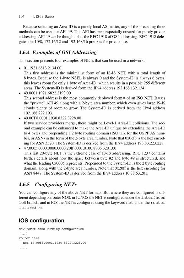
Because selecting an Area-ID is a purely local AS matter, any of the preceding threemethods can be used, or AFI 49. This AFI has been especially created for purely privateaddressing. AFI 49 can be thought of as the RFC 1918 of OSI addressing. RFC 1918 dele-gates the 10/8, 172.16/12 and 192.168/16 prefixes for private use.
4.6.4 Examples of OSI AddressingThis section presents four examples of NETs that can be used in a network.
• 01.1921.6813.2134.00This first address is the minimalist form of an IS-IS NET, with a total length of 8 bytes. Because the 1-byte NSEL is always 0 and the System-ID is always 6 bytes,this leaves room for only 1 byte of Area-ID, which results in a possible 255 differentareas. The System-ID is derived from the IPv4 address 192.168.132.134.
• 49.0001.1921.6822.2193.00This second address is the most commonly deployed format of an ISO NET. It usesthe “private” AFI 49 along with a 2-byte area number, which even gives large IS-ISclouds plenty of room to grow. The System-ID is derived from the IPv4 address192.168.222.193.
• 49.0CF8.0001.1930.8322.3228.00If two service providers merge, there might be Level-1 Area-ID collisions. The sec-ond example can be enhanced to make the Area-ID unique by extending the Area-IDto 4 bytes and prepending a 2 byte routing domain (ISO talk for the OSPF AS num-ber, or ASN) in the form of the 2-byte area number. Note that 0x0cf8 is the hex encod-ing for ASN 3320. The System-ID is derived from the IPv4 address 193.83.223.228.
• 47.0005.0000.0000.0000.20ff.0001.0100.8806.3201.00This last 20-byte NET is the extreme case of IS-IS addressing. RFC 1237 containsfurther details about how the space between byte #2 and byte #9 is structured, andwhat the leading 0x0005 represents. Prepended to the System-ID is the 2 byte routingdomain, along with the 2-byte area number. Note that 0x20ff is the hex encoding forASN 8447. The System-ID is derived from the IPv4 address 10.88.63.201.
4.6.5 Configuring NETsYou can configure any of the above NET formats. But where they are configured is dif-ferent depending on router NOS: in JUNOS the NET is configured under the interfaceslo0 branch, and in IOS the NET is configured using the keyword net under the routerisis section.
IOS configurationNew-York# show running-configuration
[ … ]
router isis
net 49.0cf8.0001.1930.8322.3228.00
[ … ]
104 4. IS-IS Basics

JUNOS configurationhannes@London> show configuration
[…]
interfaces {
lo0 {
unit 0 {
family inet {
address 172.31.208.1/32;
}
family iso {
address 49.0cf8.0001.1930.8322.3228.00;
}
}
}
}
[…]
You can configure any of these formats on JUNOS, by setting the address under thefamily iso statement on any interface. Normally, the virtual loopback interfacelo0 is used, just for consistency.
4.7 Names, System-, LAN- and LSP-IDs
Even if it is simple to derive System-IDs from IP addresses, in a modestly large networkthere might be several different types of conversion schemes. Troubleshooting such anetwork is not an easy task, as you always need to remember what conversion scheme anode’s System-ID has been based on. Troubleshooting a large set of adjacencies alsoposes a problem, because looking at a long listing of System-IDs (which have little to dowith the IP addresses on the routers), it is not always easy to find out what router corres-ponds to the Down adjacency.
JUNOS configurationhannes@London> show isis adjacency
[ … ]
show isis adjacency
Interface System L State Hold (secs) SNPA
so-4/2/0.0 1921.6800.1014 2 Up 26
so-5/2/0.0 1921.6800.1018 2 Up 27
so-5/3/0.0 1921.6800.1011 3 Up 25
so-6/2/0.0 1921.6800.1012 3 Up 28
so-6/3/0.0 1921.6800.1012 3 Up 27
[ … ]
However, exactly the same problem is also known to OSPF deployments: it is some-times very awkward to troubleshoot adjacencies from just a big list of IP addresses. Thehuman brain is simply not built for doing pattern matches on IP addresses (evolution
Names, System-, LAN- and LSP-IDs 105
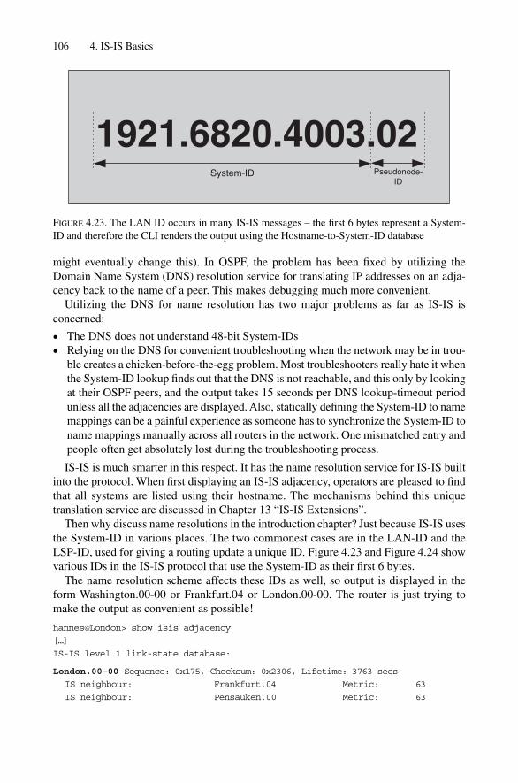
might eventually change this). In OSPF, the problem has been fixed by utilizing theDomain Name System (DNS) resolution service for translating IP addresses on an adja-cency back to the name of a peer. This makes debugging much more convenient.
Utilizing the DNS for name resolution has two major problems as far as IS-IS is concerned:
• The DNS does not understand 48-bit System-IDs• Relying on the DNS for convenient troubleshooting when the network may be in trou-
ble creates a chicken-before-the-egg problem. Most troubleshooters really hate it whenthe System-ID lookup finds out that the DNS is not reachable, and this only by lookingat their OSPF peers, and the output takes 15 seconds per DNS lookup-timeout periodunless all the adjacencies are displayed. Also, statically defining the System-ID to namemappings can be a painful experience as someone has to synchronize the System-ID toname mappings manually across all routers in the network. One mismatched entry andpeople often get absolutely lost during the troubleshooting process.
IS-IS is much smarter in this respect. It has the name resolution service for IS-IS builtinto the protocol. When first displaying an IS-IS adjacency, operators are pleased to findthat all systems are listed using their hostname. The mechanisms behind this uniquetranslation service are discussed in Chapter 13 “IS-IS Extensions”.
Then why discuss name resolutions in the introduction chapter? Just because IS-IS usesthe System-ID in various places. The two commonest cases are in the LAN-ID and theLSP-ID, used for giving a routing update a unique ID. Figure 4.23 and Figure 4.24 showvarious IDs in the IS-IS protocol that use the System-ID as their first 6 bytes.
The name resolution scheme affects these IDs as well, so output is displayed in theform Washington.00-00 or Frankfurt.04 or London.00-00. The router is just trying tomake the output as convenient as possible!
hannes@London> show isis adjacency
[…]
IS-IS level 1 link-state database:
London.00–00 Sequence: 0x175, Checksum: 0x2306, Lifetime: 3763 secs
IS neighbour: Frankfurt.04 Metric: 63
IS neighbour: Pensauken.00 Metric: 63
106 4. IS-IS Basics
1921.6820.4003.02System-ID Pseudonode-
ID
FIGURE 4.23. The LAN ID occurs in many IS-IS messages – the first 6 bytes represent a System-ID and therefore the CLI renders the output using the Hostname-to-System-ID database

The System-ID field of the LSP-ID is displayed as a name. However, the originrouter’s System-ID is displayed with the show isis hostname command (the samein IOS and JUNOS), which displays the hostname cache on the local router.
IOS commandIOS marks the local node with an asterisk (*):
Frankfurt#show isis hostname
Level System ID Dynamic Hostname
1921.6800.1013 London
* 1921.6800.1014 Frankfurt
1921.6800.1018 Washington
[…]
JUNOS commandJUNOS displays in addition if the entry has been learned via other routers, or if it hasbeen locally configured. The local node is always marked “Static”.
hannes@London> show isis hostname
IS-IS hostname database:
System ID Hostname Type
1921.6800.1013 London Static
1921.6800.1014 Frankfurt Dynamic
1921.6800.1018 Washington Dynamic
[…]
4.8 Summary
This chapter explored the foundations of IS-IS. The independence of area addressing androuting hierarchy was contrasted to the OSPF model where Area 0 implicitly makes up a
Names, System-, LAN- and LSP-IDs 107
1921.6820.4003.02-00System-ID Pseudonode-
IDFragment-
ID
FIGURE 4.24. The LSP-ID uniquely identifies an IS-IS router announcement – the first 6 bytes represent the System-ID of the sender therefore the CLI renders the output using the Hostname-to-System-ID database
routing hierarchy. The concept of an arbitrarily assigned level to the underlying physicaltopology was explained. This flexibility allows IS-IS to make very resilient POP top-ology without spending extra costs for physical intra-POP links just to heal the topology.The IP addressing model and the OSI addressing model were discussed in a comparativeway; interestingly, the IS-IS model corresponds almost exactly to the unnumbered IProuting model. IS-IS inherits its addressing structure from the OSI suite of protocols.Address assignment is a relatively easy task. The fixed part of the NET can be calculatedbased on the IP loopback address of the router and/or the POP/topology codes that areunique to each service provider. The Area-ID is the only variable part in the system, andbased on network size, most IS-IS networks use 3 or 5 byte Area-IDs. Most Area-IDsstart with 49 because the 49/8 prefix has been allocated for private use – it is the RFC1918 of the OSI suite. Finally, this chapter presented the IS-IS built-in name resolutionservice and several commands to display those ID formats which benefit from the addressresolution service as well.
108 4. IS-IS Basics

Virtually all routing (and signalling) protocols include a method of automatic neighbourdiscovery that enables a router to determine if there are any other adjacent routers runningthe same routing protocol. Once you enable IS-IS on an interface, the routing protocolwill automatically find out if there are other routers out there speaking the same protocoland version and immediately start to interact with these remote routers. Additionally therouting protocol needs to verify if the link is two-way capable (that is, equally able to passprotocol traffic in both directions) before it can announce a Reachability Information TLVin a link-state PDU (LSP) and flood it throughout the topology. This verification of linkcapabilities and bi-directional checks is done using a process known as handshaking. Thischapter examines how IS-IS routers perform neighbour discovery and handshaking onLAN and WAN circuits. Additionally, different properties of handshaking methods, such asthe simple 2-way handshake and the inherent problems of using this 2-way handshakingmethod are discussed.
You will also learn the details of adjacency finite state machine changes and networkstability improvement techniques like adjacency hold downs. Finally, requirements ofhighly resilient neighbour “liveness” checking will be presented and popular solutionswill be explored including technologies like bi-directional fault detection. Everythingwill include configuration snippets, show command and debug output, plus tcpdump out-put for a better understanding of the IS-IS protocol.
5.1 Hello Message Encoding
Each routing protocol uses Hello messages for neighbour discovery and to performhandshaking. In IS-IS, just like in any other routing protocol, this function is performedthrough the use of what IS-IS calls Intermediate System to Intermediate System Hello(IIH) messages. IS-IS uses dedicated IIH messages for the two types of topologies arouter can be configured to be a member of: there is one Hello type for the Level 1 adja-cencies and one Hello type for the Level 2 adjacencies. There are more details about theIS-IS hierarchical Level 1/Level 2 routing paradigm in Chapter 4 “IS-IS Basics”.
IS-IS supports two different circuit types: point-to-point (p2p) and broadcast LAN cir-cuits. There is a dedicated type of Hello Message for point-to-point circuits and anotherone for broadcast circuits. So in theory there should be two Hello messages for each cir-cuit type (point-to-point or broadcast) and two Hello message types for each Level, L1or L2. This should total four distinct Hello message types.
109
5
Neighbour Discovery and Handshaking

In ISO 10589, however, there was some concern that running two Hellos (one perlevel) on point-to-point links would consume too much bandwidth on narrow-band links.So IS-IS is optimized for point-to-point circuits and only uses one PDU type for both levels. Figure 5.1 shows the structure of the IS-IS common header, which starts every IS-ISmessage. The 8-bit PDU type field indicates the type of message that is carried inside theIS-IS message. On the right of the figure there is a list of the nine distinct PDU types forIS-IS. Three out of the nine PDU types are reserved for Hello messages. The point-to-point circuit types share one PDU type (17) for both levels, so there are not really four different Hello messages but only three.
What do the Hello messages look like on the wire? Each IS-IS message type isprepended with an 8-byte common header that tells the receiver about the IS-IS protocolversion being used, the header length, the maximum number of concurrent areas sup-ported, as well as other IS-IS global parameters, such as the length of the System-IDfield. Figure 5.1 shows the structure of the common header that is prepended to all IS-ISrelated messages. In the figure, you can see that some of the fields are already filled inwith number values. We have chosen not only to show the frame structure, but also toshow how the frames are populated with number values. These numbers represent con-stants and fill in the common header with typical values. It is interesting to note that someheader fields, such as the number of supported areas and the length of the System-IDfield, are set to zero. Zero has a special meaning in IS-IS. Using the zero value is equiv-alent to telling routers to use the default value for a field, which is not typically zero.
110 5. Neighbour Discovery and Handshaking
Intra-domain routing protocol discriminator
Header Length Indicator
Version/Protocol ID Extension
0x83
Bytes
1
1
1
1
1
1
1
1
1
ID Length
PDU TypeR0
R0
R0
PDU Version
Reserved
Maximum Area Addresses
6 (0)
1
3 (0)
0
PDU specific fields 17–33
TLV section 0–1467
151617182024252627
Level 1 LAN HelloLevel 2 LAN Hello p2p HelloLevel 1 Link State PDULevel 2 Link State PDULevel 1 CSNPLevel 2 CSNPLevel 1 PSNPLevel 2 PSNP
PDUType
Name
15
Level LAN circuit p2p circuit
1
2 1617
FIGURE 5.1. Three out of the nine IS-IS PDU types are allocated for Hello messages on p2p andbroadcast circuits
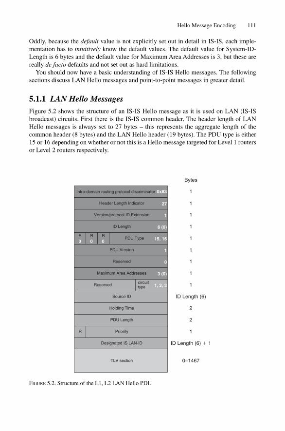
Oddly, because the default value is not explicitly set out in detail in IS-IS, each imple-mentation has to intuitively know the default values. The default value for System-ID-Length is 6 bytes and the default value for Maximum Area Addresses is 3, but these arereally de facto defaults and not set out as hard limitations.
You should now have a basic understanding of IS-IS Hello messages. The followingsections discuss LAN Hello messages and point-to-point messages in greater detail.
5.1.1 LAN Hello MessagesFigure 5.2 shows the structure of an IS-IS Hello message as it is used on LAN (IS-ISbroadcast) circuits. First there is the IS-IS common header. The header length of LANHello messages is always set to 27 bytes – this represents the aggregate length of thecommon header (8 bytes) and the LAN Hello header (19 bytes). The PDU type is either15 or 16 depending on whether or not this is a Hello message targeted for Level 1 routersor Level 2 routers respectively.
Hello Message Encoding 111
Intra-domain routing protocol discriminator
Header Length Indicator
Version/protocol ID Extension
0x83
Bytes
1
1
1
1
1
1
1
1
1
ID Length
PDU TypeR
0R
0R
0
PDU Version
Reserved
Maximum Area Addresses
6 (0)
1
3 (0)
0
Reserved
TLV section 0–1467
15, 16
27
circuittype 1, 2, 3
Source ID
Holding Time
PDU Length
PriorityR
Designated IS LAN-ID
1
ID Length (6)
2
2
1
ID Length (6) � 1
FIGURE 5.2. Structure of the L1, L2 LAN Hello PDU
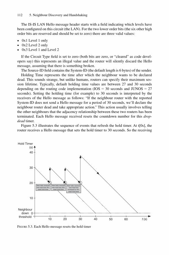
The IS-IS LAN Hello message header starts with a field indicating which levels havebeen configured on this circuit (the LAN). For the two lower order bits (the six other highorder bits are reserved and should be set to zero) there are three valid values:
• 0x1 Level 1 only• 0x2 Level 2 only• 0x3 Level 1 and Level 2
If the Circuit Type field is set to zero (both bits are zero, or “cleared” as code devel-opers say) this represents an illegal value and the router will silently discard the Hellomessage, assuming that there is something broken.
The Source-ID field contains the System-ID (the default length is 6 bytes) of the sender.Holding Time represents the time after which the neighbour wants to be declared
dead. This sounds strange, but unlike humans, routers can specify their maximum ses-sion lifetime. Typically, default holding time values are between 27 and 30 secondsdepending on the routing code implementation (IOS � 30 seconds and JUNOS � 27seconds). Setting the holding time (for example) to 30 seconds is interpreted by thereceivers of the Hello message as follows: “If the neighbour router with the reportedSystem-ID does not send a Hello message for a period of 30 seconds, we’ll declare theneighbour router dead and take appropriate action.” This action usually involves tellingthe other neighbours that the adjacency relationship between these two routers has beenterminated. Each Hello message received resets the countdown number for this drop-dead timer.
Figure 5.3 illustrates the sequence of events that refresh the hold timer. At t[0s], therouter receives a Hello message that sets the hold timer to 30 seconds. So the receiving
112 5. Neighbour Discovery and Handshaking
Neighbourdown
threshold
40
30
20
10
0
Hold Timer(s)
10 20 30 40 50 60
New hello receivednew hold time 30s,
reset hold timer
t (s)
New hello receivednew hold time 30s,
reset hold timer
New hello receivednew hold time
increased to 40s,reset hold timer
FIGURE 5.3. Each Hello message resets the hold timer
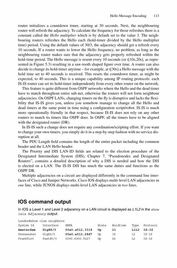
router initializes a countdown timer, starting at 30 seconds. Next, the neighbouringrouter will refresh the adjacency. To calculate the frequency for those refreshes there is aconstant called the Hello multiplier which is by default set to the value 3. The neigh-bouring routers refreshes the Hello each (hold-timer divided by the Hello multipliertime) period. Using the default values of 30/3, the adjacency should get a refresh every10 seconds. If a router wants to lower the Hello frequency, no problem, as long as theneighbouring router makes sure that the adjacency gets properly refreshed within thehold-time period. The Hello message is resent every 10 seconds (or t[10s,20s], as repre-sented in Figure 5.3) resulting in a saw-tooth shaped figure over time. A router can alsodecide to change its hold-timer anytime – for example, at t[30s] a Hello message with thehold time set to 40 seconds is received. This resets the countdown timer, as might beexpected, to 40 seconds. This is a unique capability among IP routing protocols: each IS-IS router can set its hold-timer independently from every other router on the network.
This feature is quite different from OSPF networks where the Hello and the dead timerhave to match throughout entire sub-net, otherwise the routers will not form neighbouradjacencies. On OSPF LANs, changing timers on the fly is disruptive and lacks the flexi-bility that IS-IS gives you, unless you somehow manage to change all the Hello and dead timers at the same point in time using a configuration script/robot. IS-IS is muchmore operationally friendly in that respect, because IS-IS does not rely on any otherrouters to match its timers like OSPF does. In OSPF, all the timers have to be alignedwith the designated router (DR).
In IS-IS such a change does not require any coordination/scripting effort. If you wantto change your own timers, you simply do it in a step-by-step fashion with no service dis-ruption at all.
The PDU Length field contains the length of the entire packet including the commonheader and the LAN Hello header.
The Priority and DIS LAN-ID fields are related to the election procedure of theDesignated Intermediate System (DIS). Chapter 7, “Pseudonodes and DesignatedRouters”, contains a detailed description of why a DIS is needed and how the DIS is elected on a LAN. The IS-IS DIS has much the same duties and functions as the OSPF DR.
Multiple adjacencies on a circuit are displayed differently in the command line inter-faces of Cisco and Juniper Networks. Cisco IOS displays multi-level LAN adjacencies inone line, while JUNOS displays multi-level LAN adjacencies in two lines.
IOS command outputIn IOS a Level 1 and Level 2 adjacency on a LAN circuit is displayed as L1L2 in the showisis Adjacency output.
London#show clns neighbors
System Id Interface SNPA State Holdtime Type Protocol
Amsterdam GigE8/0 00a0.a512.3318 Up 21 L1L2 IS-IS
Pennsauken GigE4/0 00a0.a512.28d7 Up 18 L2 IS-IS
Frankfurt FastE5/0 0090.6900.fe27 Up 24 L2 IS-IS
Hello Message Encoding 113
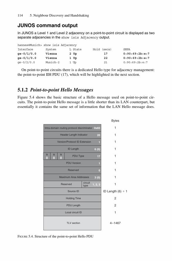
114 5. Neighbour Discovery and Handshaking
Intra-domain routing protocol discriminator
Header Length Indicator
Version/Protocol ID Extension
0x83
Bytes
1
1
1
1
1
1
1
1
1
ID Length
PDU TypeR
0R
0R
0
PDU Version
Reserved
Maximum Area Addresses
6 (0)
1
3 (0)
0
Reserved
TLV section 4–1467
17
20
circuittype 1, 2, 3
Source ID
Holding Time
PDU Length
Local circuit ID
1
ID Length (6) � 1
2
2
1
FIGURE 5.4. Structure of the point-to-point Hello PDU
JUNOS command outputIn JUNOS a Level 1 and Level 2 adjacency on a point-to-point circuit is displayed as twoseparate adjacencies in the show isis Adjacency output.
hannes@Munich> show isis Adjacency
Interface System L State Hold (secs) SNPA
ge-0/1/0.0 Vienna 2 Up 17 0:90:69:2b:e:7
ge-0/1/0.0 Vienna 1 Up 22 0:90:69:2b:e:7
ge-0/2/0.0 Munich-2 1 Up 21 0:90:69:2b:e:7
On point-to-point circuits there is a dedicated Hello type for adjacency management:the point-to-point IIH PDU (17), which will be highlighted in the next section.
5.1.2 Point-to-point Hello MessagesFigure 5.4 shows the basic structure of a Hello message used on point-to-point cir-cuits. The point-to-point Hello message is a little shorter than its LAN counterpart, but essentially it contains the same set of information that the LAN Hello message does.

For instance, the point-to-point Hello contains:
• Circuit Type• Source ID• Holding Time• PDU Length
All of these fields have the same meaning and function as in the LAN Hello. Note thatthe Designated Router and Priority fields are missing. That’s because on point-to-pointcircuits there is no election of a designated router, and so the point-to-point Hello mes-sage does not need to carry the Priority and DIS LAN-ID fields.
Additionally, there is the Local Circuit-ID field that carries the link’s circuit numberThe IS-IS specification leaves it quite open as to what value should be inserted for theLocal Circuit-ID. For example, in the IOS implementation, the Interface Index of thesender’s interface is taken as the Local Circuit-ID. The JUNOS implementation alwayssets this value to 0x1. The JUNOS implementers of this “constant” Local Circuit-IDargue that the Circuit-ID is not needed anywhere for processing, such as in SPF calcula-tions, timer countdowns, or anything else. The Local Circuit-ID is there for purely link-local informational purposes. And if something has just informational purposes, then noharm can be done by not setting it to anything other than a constant.
How can IS-IS build both Level 1 and Level 2 adjacencies on a point-to-point link with justone message type? Figure 5.2 showed that LAN Hellos have two PDU types, one for eachlevel, whereas point-to-point Hellos share one PDU type for both levels. The difference in pro-cessing the point-to-point Hello compared to the LAN Hello is that receipt of a point-to-pointHello resets the hold timers for all levels, as indicated in the Circuit Type field. For example,if the Circuit Type field indicates that this is just a Level 1 adjacency, then just the hold timerof Level 1 is reset. The same logic goes for Level 2 and Level 1/Level 2 capable circuits –whatever level is indicated in the Circuit Type, those corresponding hold timers get reset.
In contrast to point-to-point Hellos, receipt of a LAN Hello just resets the hold timeraccording to the PDU type. A received Hello containing PDU Type 15 just resets theLevel 1 hold timer, while a PDU Type 16 resets the Level 2 hold timer only.
Command line interfaces of routers have different ways of displaying a joint Level1/Level 2 adjacency. For example, JUNOS displays an L1L2 adjacency on a point-to-point circuit as Level 3. Of course there is (yet) no Level 3, but the reason for this is sim-ple: if you take the bit patterns of a Level 2 circuit (10b) plus the bit pattern of a Level 1circuit (01b) the sum equals to (11b), which is the binary value for 3.
JUNOS command outputIn JUNOS a Level 1 and Level 2 adjacency on a point-to-point circuit is displayed as Level 3 in the show isis Adjacency output.
hannes@Frankfurt> show isis Adjacency
Interface System L State Hold (secs) SNPA
so-0/0/0.0 Munich 3 Up 28
so-0/1/0.0 London 2 Up 27
so-0/2/0.0 Milan 2 Up 25
so-1/0/0.0 paris 2 Up 24
Hello Message Encoding 115
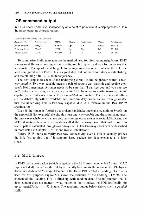
IOS command outputIn IOS a Level 1 and Level 2 adjacency on a point-to-point circuit is displayed as L1L2 inthe show clns neighbors output.
London#show clns neighbors
System Id Interface SNPA State Holdtime Type Protocol
Amsterdam PO4/0 *PPP* Up 19 L1L2 IS-IS
Pennsauken PO4/1 *PPP* Up 18 L2 IS-IS
Frankfurt PO4/1 *PPP* Up 24 L2 IS-IS
To summarize, Hello messages are the method used for discovering neighbours. IS-ISrouters send Hellos according to their configured link types, and wait for responses thatare a match. Receipt of a matching Hello message means another router on the link is atleast configured to run IS-IS. This is a good start, but not the whole story of establishingand maintaining a full IS-IS router adjacency.
The next step is to check if the underlying circuit to the neighbour router is two-way capable. Two-way capable means a pair of routers can transmit and receive theirpeer’s Hello messages. A router needs to be sure that “I can see you and you can see me”, before advertising an adjacency in its LSP. In order to verify two-way circuit capability the router needs to perform a handshaking function. There are several differ-ent handshake algorithms available and, unfortunately, some cannot even guarantee that the underlying link is two-way capable, due to a mistake in the ISO 10589 specification.
Even if the router is fooled by a broken handshake mechanism, nothing breaks onthe network if (for example) the circuit is just one-way capable and the router announcesthe one-way reachability (I can see you, but you cannot see me) in its router LSP. During theSPF calculation there is a verification called the two-way check that makes sure no transit path is calculated through a one-way circuit. The two-way check will be describedin more detail in Chapter 10 “SPF and Route Calculation”.
Before IS-IS starts to verify two-way connectivity over a link it actually probes the link first to find out if it supports large packets for data exchange at a later stage.
5.2 MTU Check
In IS-IS the largest packet (which is typically the LSP) may become 1492 bytes (MAClayer excluded). IS-IS tests the link by artificially bloating its Hello size up to 1492 bytes.There is a dedicated Message Element in the Hello PDU called a Padding TLV that isused for this purpose. Figure 5.5 shows the structure of the Padding TLV #8. The content of the Padding TLV is filled up with random data. The information that it does contain does not matter – what matters is that it makes the PDU artificially big up to maxLSPsize (�1492 bytes). The tcpdump output below shows such a paddedHello.
116 5. Neighbour Discovery and Handshaking

Tcpdump output20:16:37.411690 OSI, IS-IS, length: 1492
L1 Lan IIH, hlen: 27, v: 1, pdu-v: 1, sys-id-len: 6 (0), max-area: 3 (0)
source-id: 1921.6800.1008, holding time: 120s, Flags: [L1, L2]
lan-id: 1921.6800.1008.02, Priority: 64, PDU length: 1492
IS Neighbor(s) TLV #6, length: 6
SNPA: 0090.692b.0e52
Protocols supported TLV #129, length: 1
NLPID(s): IPv4 (0xcc)
IPv4 Interface address(es) TLV #132, length: 4
IPv4 interface address: 193.83.223.236
Area address(es) TLV #1, length: 4
Area address (length: 3): 49.0001
Restart Signaling TLV #211, length: 3
Flags [none], Remaining holding time 0s
Padding TLV #8, length: 255
Padding TLV #8, length: 255
Padding TLV #8, length: 255
Padding TLV #8, length: 255
Padding TLV #8, length: 255
Padding TLV #8, length: 150
If a router exchanges these bloated Hello PDUs in both directions then it can be surethat the underlying media sufficiently supports the maximum packet sizes necessary forIS-IS.
IOS and JUNOS do have different styles of how and when they do implement adja-cency checks. IOS pads each and every Hello that it transmits on the wire. On large WANHub Routers that terminate a lot of circuits – for example on a Router running Framerelay or ATM circuits – periodic emission of large packets can be a burden to the control plane processor. If you know that your underlying link supports at least 1492 bytes sized packets then you can turn off the artificial bloating of Hello PDUs usingthe no hello padding router configuration command.
MTU Check 117
TLV Type
TLV Length
Padding Data
8
Bytes
1
1
1–255
FIGURE 5.5. The Padding TLV #8 is used to bloat IIHs up to at least 1492 bytes
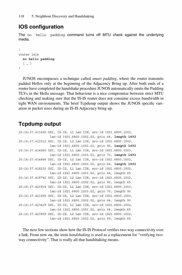
IOS configurationThe no hello padding command turns off MTU check against the underlying media.
!
router isis
no hello padding
[ … ]
!
JUNOS encompasses a technique called smart padding, where the router transmitspadded Hellos only at the beginning of the Adjacency Bring up. After both ends of arouter have completed the handshake procedure JUNOS automatically omits the PaddingTLVs in the Hello message. That behaviour is a nice compromise between strict MTUchecking and making sure that the IS-IS router does not consume excess bandwidth intight WAN environments. The brief Tcpdump output shows the JUNOS specific vari-ation in packet sizes during an IS-IS Adjacency bring up.
Tcpdump output20:16:37.411690 OSI, IS-IS, L1 Lan IIH, src-id 1921.6800.1002,
lan-id 1921.6800.1002.02, prio 64, length 1492
20:16:37.412312 OSI, IS-IS, L2 Lan IIH, src-id 1921.6800.1002,
lan-id 1921.6800.1002.02, prio 90, length 1492
20:16:37.414060 OSI, IS-IS, L1 Lan IIH, src-id 1921.6800.1003,
lan-id 1921.6800.1003.02, prio 70, length 1492
20:16:37.414466 OSI, IS-IS, L2 Lan IIH, src-id 1921.6800.1003,
lan-id 1921.6800.1003.02, prio 64, length 1492
20:16:37.418232 OSI, IS-IS, L1 Lan IIH, src-id 1921.6800.1002,
lan-id 1921.6800.1003.02, prio 64, length 65
20:16:37.418742 OSI, IS-IS, L2 Lan IIH, src-id 1921.6800.1002,
lan-id 1921.6800.1002.02, prio 90, length 65
20:16:37.420914 OSI, IS-IS, L1 Lan IIH, src-id 1921.6800.1003,
lan-id 1921.6800.1003.02, prio 70, length 90
20:16:37.421055 OSI, IS-IS, L2 Lan IIH, src-id 1921.6800.1003,
lan-id 1921.6800.1002.02, prio 64, length 90
20:16:37.423429 OSI, IS-IS, L1 Lan IIH, src-id 1921.6800.1002,
lan-id 1921.6800.1003.02, prio 64, length 65
20:16:37.423909 OSI, IS-IS, L2 Lan IIH, src-id 1921.6800.1002,
lan-id 1921.6800.1002.02, prio 90, length 65
The next few sections show how the IS-IS Protocol verifies two-way connectivity overa link. From now on, the term handshaking is used as a replacement for “verifying two-way connectivity”. That is really all that handshaking means.
118 5. Neighbour Discovery and Handshaking
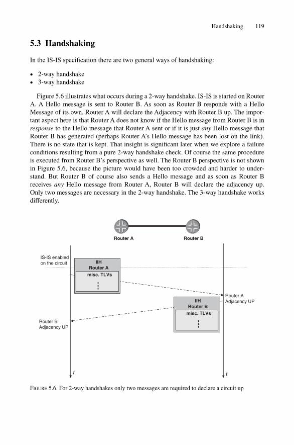
5.3 Handshaking
In the IS-IS specification there are two general ways of handshaking:
• 2-way handshake• 3-way handshake
Figure 5.6 illustrates what occurs during a 2-way handshake. IS-IS is started on RouterA. A Hello message is sent to Router B. As soon as Router B responds with a HelloMessage of its own, Router A will declare the Adjacency with Router B up. The impor-tant aspect here is that Router A does not know if the Hello message from Router B is inresponse to the Hello message that Router A sent or if it is just any Hello message thatRouter B has generated (perhaps Router A’s Hello message has been lost on the link).There is no state that is kept. That insight is significant later when we explore a failureconditions resulting from a pure 2-way handshake check. Of course the same procedureis executed from Router B’s perspective as well. The Router B perspective is not shownin Figure 5.6, because the picture would have been too crowded and harder to under-stand. But Router B of course also sends a Hello message and as soon as Router Breceives any Hello message from Router A, Router B will declare the adjacency up. Only two messages are necessary in the 2-way handshake. The 3-way handshake worksdifferently.
Handshaking 119
Router A Router B
tt
Router BAdjacency UP
IIHRouter A
misc. TLVs
IIHRouter B
misc. TLVs
IS-IS enabledon the circuit
Router AAdjacency UP
FIGURE 5.6. For 2-way handshakes only two messages are required to declare a circuit up

Figure 5.7 shows a 3-way handshake transition. Router A first sends the Hello mes-sage out, just as before. Next, Router B responds with a Hello message. Router A willknow that this Hello was not sent by accident (in the 2-way case Router A never reallyknows) because the Hello message from Router B carries an indication that this Hellohas been sent in response to Router A’s original Hello. This is done by mentioning RouterA explicitly in the message body, by means of a special TLV. Later, in the finite statemachine section such an event is described as Seenself. Router B receives Router A’sHello message and now realizes that it has been seen by the neighbour (Router A) anddeclares the adjacency up. Router A now responds by sending a third Hello messageback to Router B confirming that it has also seen Router B’s Hello message, whichcauses Router B to declare the adjacency (from its perspective) now up as well. The 3-way handshake is a stateful transition and much more robust than the simple 2-wayversion, but does require an extra message.
IS-IS uses different message elements and handshaking methods depending onwhether it is performing the handshaking on LAN or on point-to-point circuits. The following section shows where and in which environment the different handshakingmethods are used, and what TLVs are encoded in the Hello messages to convey neigh-bour adjacency state in IS-IS.
5.3.1 The 3-way Handshake on LAN CircuitsOn LANs, IS-IS uses a 3-way handshake. Figure 5.8 shows the state changes on the LANfrom Router A’s perspective. Please note that for better visibility again, only the state
120 5. Neighbour Discovery and Handshaking
tt
Router BAdjacency UP
IIHRouter A
misc. TLVs
IIHRouter B
“I have seen Router A”
&
IS-IS enabledon the circuit
IIHRouter A
“I have seen Router B”
&
Router AAdjacency UP
Router A Router B
misc. TLVs
misc. TLVs
FIGURE 5.7. The 3-way handshake is a stateful transition

tt
Ro
ute
r A
MA
C 0
090.
69aa
.aaa
aR
ou
ter
BM
AC
000
0.0c
bb
.bb
bb
Ro
ute
r C
MA
C 0
090.
69cc
.ccc
c
t
Rou
ter
CA
djac
ency
UP
IS-I
S e
nabl
edon
the
circ
uit
Rou
ter
AA
djac
ency
UP
IIHR
ou
ter
C
I’ve
See
nM
AC
009
0.69
aa.a
aaa
mis
c. T
LV
s
IIHR
ou
ter
A
mis
c. T
LV
s
IIHR
ou
ter
B
I’ve
See
nM
AC
009
0.69
aa.a
aaa
mis
c. T
LV
s
Rou
ter
BA
djac
ency
UP
IIHR
ou
ter
A
I’ve
See
nM
AC
000
0.0c
bb
.bb
bb
MA
C 0
090.
69cc
.ccc
cm
isc.
TL
Vs
Rou
ter
AA
djac
ency
UP
FIG
UR
E5.
8.O
n L
AN
s th
e ro
uter
s ne
ed to
sen
d a
list o
f vi
sibl
e ne
ighb
ours
to c
ompl
ete
the
3-w
ay h
ands
hake
121
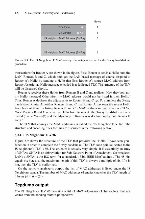
transactions for Router A are shown in the figure. First, Router A sends a Hello onto theLAN. Routers B and C, which both get the LAN-based message of course, respond toRouter A’s Hello by sending a Hello that lists Router A’s source MAC address fromRouter A’s original Hello message encoded in a dedicated TLV. The structure of the TLVwill be discussed shortly.
Router A receives these Hellos from Routers B and C and realizes “Hey, they both gotmy Hello message! Otherwise, my MAC address would not be listed in their Hello.”Thus, Router A declares the adjacencies to Router B and C up. To complete the 3-wayhandshake, Router A notifies Routers B and C that Router A has seen the recent Hellofrom both of them by listing Router B and C’s MAC address in one of its own TLVs.Once Routers B and C receive the Hello from Router A, the 3-way handshake is com-pleted (due to Seenself ) and the adjacency to Router A is declared up by both Router Band C.
The TLV that conveys the MAC addresses is called the “IS Neighbor TLV #6”. Thestructure and encoding rules for this are discussed in the following section.
5.3.1.1 IS Neighbour TLV #6
Figure 5.9 shows the structure of the TLV that provides the “Hello, I have seen you”function in order to complete the 3-way handshake. The TLV code point allocated to theIS neighbour’s TLV is #6. The structure is actually very simple. It is essentially an arrayof SNPAs. SNPA is an abbreviation for Sub-Network Point of Attachment. On broadcastLANs a SNPA is the ISO term for a standard, 48-bit IEEE MAC address. The 48-bitsequals six bytes, so the maximum length of this TLV is always a multiple of six. If it isnot, then the TLV is malformed.
On the network analyzer’s output, the list of MAC addresses is listed under the ISNeighbour stanza. The number of MAC addresses (4 entries) matches the TLV length of4 bytes (4 � 6 � 24).
Tcpdump outputThe IS Neighbour TLV #6 contains a list of MAC addresses of the routers that are visible from the sending router’s perspective:
122 5. Neighbour Discovery and Handshaking
TLV Type
TLV Length
IS Neighbor MAC Address (SNPA)
6
Bytes
1
1
6
N * 6
IS Neighbor MAC Address (SNPA) 6
FIGURE 5.9. The IS Neighbour TLV #6 conveys the neighbour state for the 3-way handshaking procedure
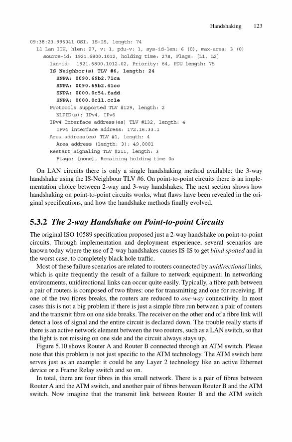
09:38:23.996041 OSI, IS-IS, length: 74
L1 Lan IIH, hlen: 27, v: 1, pdu-v: 1, sys-id-len: 6 (0), max-area: 3 (0)
source-id: 1921.6800.1012, holding time: 27s, Flags: [L1, L2]
lan-id: 1921.6800.1012.02, Priority: 64, PDU length: 75
IS Neighbor(s) TLV #6, length: 24
SNPA: 0090.69b2.71ca
SNPA: 0090.69b2.41cc
SNPA: 0000.0c54.fadd
SNPA: 0000.0c11.cc1e
Protocols supported TLV #129, length: 2
NLPID(s): IPv4, IPv6
IPv4 Interface address(es) TLV #132, length: 4
IPv4 interface address: 172.16.33.1
Area address(es) TLV #1, length: 4
Area address (length: 3): 49.0001
Restart Signaling TLV #211, length: 3
Flags: [none], Remaining holding time 0s
On LAN circuits there is only a single handshaking method available: the 3-way handshake using the IS-Neighbour TLV #6. On point-to-point circuits there is an imple-mentation choice between 2-way and 3-way handshakes. The next section shows howhandshaking on point-to-point circuits works, what flaws have been revealed in the ori-ginal specifications, and how the handshake methods finally evolved.
5.3.2 The 2-way Handshake on Point-to-point CircuitsThe original ISO 10589 specification proposed just a 2-way handshake on point-to-pointcircuits. Through implementation and deployment experience, several scenarios areknown today where the use of 2-way handshakes causes IS-IS to get blind spotted and inthe worst case, to completely black hole traffic.
Most of these failure scenarios are related to routers connected by unidirectional links,which is quite frequently the result of a failure to network equipment. In networkingenvironments, unidirectional links can occur quite easily. Typically, a fibre path betweena pair of routers is composed of two fibres: one for transmitting and one for receiving. Ifone of the two fibres breaks, the routers are reduced to one-way connectivity. In mostcases this is not a big problem if there is just a simple fibre run between a pair of routersand the transmit fibre on one side breaks. The receiver on the other end of a fibre link willdetect a loss of signal and the entire circuit is declared down. The trouble really starts ifthere is an active network element between the two routers, such as a LAN switch, so thatthe light is not missing on one side and the circuit always stays up.
Figure 5.10 shows Router A and Router B connected through an ATM switch. Pleasenote that this problem is not just specific to the ATM technology. The ATM switch hereserves just as an example: it could be any Layer 2 technology like an active Ethernetdevice or a Frame Relay switch and so on.
In total, there are four fibres in this small network. There is a pair of fibres betweenRouter A and the ATM switch, and another pair of fibres between Router B and the ATMswitch. Now imagine that the transmit link between Router B and the ATM switch
Handshaking 123
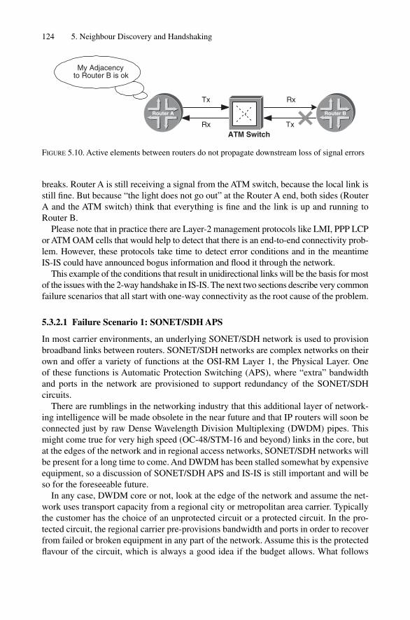
breaks. Router A is still receiving a signal from the ATM switch, because the local link isstill fine. But because “the light does not go out” at the Router A end, both sides (RouterA and the ATM switch) think that everything is fine and the link is up and running toRouter B.
Please note that in practice there are Layer-2 management protocols like LMI, PPP LCPor ATM OAM cells that would help to detect that there is an end-to-end connectivity prob-lem. However, these protocols take time to detect error conditions and in the meantime IS-IS could have announced bogus information and flood it through the network.
This example of the conditions that result in unidirectional links will be the basis for mostof the issues with the 2-way handshake in IS-IS. The next two sections describe very commonfailure scenarios that all start with one-way connectivity as the root cause of the problem.
5.3.2.1 Failure Scenario 1: SONET/SDH APS
In most carrier environments, an underlying SONET/SDH network is used to provisionbroadband links between routers. SONET/SDH networks are complex networks on theirown and offer a variety of functions at the OSI-RM Layer 1, the Physical Layer. One of these functions is Automatic Protection Switching (APS), where “extra” bandwidthand ports in the network are provisioned to support redundancy of the SONET/SDH circuits.
There are rumblings in the networking industry that this additional layer of network-ing intelligence will be made obsolete in the near future and that IP routers will soon beconnected just by raw Dense Wavelength Division Multiplexing (DWDM) pipes. Thismight come true for very high speed (OC-48/STM-16 and beyond) links in the core, butat the edges of the network and in regional access networks, SONET/SDH networks willbe present for a long time to come. And DWDM has been stalled somewhat by expensiveequipment, so a discussion of SONET/SDH APS and IS-IS is still important and will beso for the foreseeable future.
In any case, DWDM core or not, look at the edge of the network and assume the net-work uses transport capacity from a regional city or metropolitan area carrier. Typicallythe customer has the choice of an unprotected circuit or a protected circuit. In the pro-tected circuit, the regional carrier pre-provisions bandwidth and ports in order to recoverfrom failed or broken equipment in any part of the network. Assume this is the protectedflavour of the circuit, which is always a good idea if the budget allows. What follows
124 5. Neighbour Discovery and Handshaking
RxTx
Rx Tx
My Adjacencyto Router B is ok
Router BRouter A
ATM Switch
FIGURE 5.10. Active elements between routers do not propagate downstream loss of signal errors

does not require any detailed familiarity with SONET/SDH. All terms and equipmentroles are fully explained as needed.
Figure 5.11 shows a failure scenario where Router A and Router B are connected by aSONET/SDH pipe. Router A is located at the spoke site and Router B is located at thecentral hub site. Additionally, a second redundant SONET/SDH port has been pre-provisioned in case a link to one of the routers or even the router itself at the central sitefails. The SONET/SDH Add–Drop Multiplexer (ADM), the network element that links therouters at both customer sites, needs to make sure its ports are still up. In SONET/SDHnetworks, the ends of a SONET/SDH link (in this case, the routers) can send heartbeatsignalling messages in the overhead bytes of the SONET/SDH transmission frameheader for redundancy purposes. Routers A and B send heartbeat signals in order toinform the ADMs that everything is okay. If the ADM does not receive a heartbeat signalfrom the routers for a period of 50 milliseconds (ms), then the ADM will automaticallyswitch over to the backup circuit (Router C).
Note that both Router B and Router C listen on the wire for APS signalling messagesbecause the ADM connects both routers, receive fibres. However, Router C’s transmitfibre is not ordinarily active (it is not needed). This fibre only gets activated in failuremode when Router B or one of its links goes down. Realize that this is a purposeful, one-way connection for SONET/SDH APS. It is exactly this one-way connection that willcause trouble in IS-IS environments. Consider the following scenario:
1. Router A sends a Hello message2. Both Routers B and C receive the Hello message3. Router B responds with a Hello message and declares the adjacency to Router A up4. Router C also responds with a Hello message. But the Hello response does not get
through to the spoke site (no active transmit). However, Router C thinks it has suc-cessfully delivered the Hello and declares the adjacency up. So Router A knows it hasan adjacency with Router B and vice versa, which is fine. The problem is that Router Calso thinks it has an adjacency with Router A and therefore will forward trafficdown the “broken” (inactive) link, which is only to be used for APS purposes. This isa serious issue because the traffic from Router C to Router A will get black holedbecause the transmit fibre is not connected all the way through the ADM.
Handshaking 125
Central "Hub" site
Network cloud
Spoke site
Network cloud
SONET/SDHAdd drop multiplexer
(ADM)
Rx
Tx
Rx Rx
Tx
1
2
324
3Tx
Router B
Router C
Router A
FIGURE 5.11. The protected SONET circuit is creating a unidirectional link in the backup case

The whole point here is that a backup link at the Physical Layer looks like it can beused by Layer 3 (IP and IS-IS), but this is not the case. This is just a consequence of theuse of the 2-way handshake on point-to-point circuits. Scenarios like this, where trafficgets black holed, are very difficult to troubleshoot. Most Network Operation Centre(NOC) teams are fooled by the fact that the router adjacency is up and their thinking isthat the circuit must be delivering injected traffic. Trusting the 2-way handshake in thiscase leads to a serious impairment of the network.
5.3.2.2 Failure Scenario 2: Parallel Links
The previous failure scenario does not do any damage, because all the IS-IS routers in thenetwork would soon realize during the SPF calculation that Router C believes it has anadjacency with Router A, but Router A does not report an adjacency to Router C. TheSPF algorithm, which is used to calculate paths through the network, has an additionalstability rule built in. If two routers do not indicate to each other that they have an adja-cency, then the SPF algorithm disregards the adjacency between the two routers, whichmeans that no transit traffic is sent over the unidirectional link. However, based on theprevious failure condition, it is relatively easy to construct a four router scenario (tworouters on each side of the link) where both sides report a stale adjacency that ultimatelypasses the 2-way check during the SPF calculation. This example simply uses a threerouter scenario for a clearer explanation of the underlying problem. So far, we have notmentioned the details of the SPF calculation, but there will be much more about thattopic in Chapter 10 “SPF and Router Calculation”.
This section shows one other example of failure. In this example even the SPF-2-waycheck will be spoofed, which serves as a last resort protection from black holing traffic.
Consider the scenario in Figure 5.12. Here there are two routers interconnected by twocircuits composed of two fibres in each direction. Now, assume there are two fibrebreaks. The transmit fibre from Router A to Router B on circuit #1 has failed and, in addi-tion, the transmit fibre from Router B to Router A on circuit #2 is broken. Here is thesequence of events that happens:
1. Router A sends a Hello message on circuit #22. Router B responds to the Hello message on circuit #2 and declares the adjacency up3. Router B sends a Hello message on circuit #14. Router A responds to the Hello message on circuit #1 and declares the adjacency up5. Both Routers A and B tell other routers in the network that they can see each other,
when in fact they can’t because of the fibre failures mentioned earlier. This failure sce-nario passes even the check during the SPF calculation. This makes both Router A andB attract transit traffic which will be black holed by both sides.
So 2-way handshaking on point-to-point links in IS-IS suffers from robustness prob-lems in practice. Therefore the basic IS-IS protocol needs to be extended so that the morereliable 3-way handshakes are made on point-to-point circuits. Using the error-prone 2-way handshake procedure results in the set of problems generated by unidirectional linksdue to APS or multiple fibre breaks. The 3-way handshake on point-to-point circuits isdiscussed in the following section.
126 5. Neighbour Discovery and Handshaking
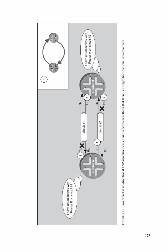
Ro
ute
r A
Ro
ute
r B
circ
uit #
1
circ
uit #
2
I hav
e an
adj
acen
cy w
ithR
oute
r B
on
circ
uit #
1
I hav
e an
adj
acen
cy w
ithR
oute
r A
on
circ
uit #
2
1
Tx
Rx
Tx
Rx
Rx
Tx Rx
Tx
23
4
5
FIG
UR
E5.
12.T
wo
repo
rted
uni
dire
ctio
nal L
SP a
dver
tisem
ents
mak
e ot
her
rout
ers
thin
k th
at th
ere
is a
sin
gle
bi-d
irec
tiona
l adv
ertis
emen
t
127

5.3.3 The 3-way Handshake on Point-to-point CircuitsIn LAN environments, the IS Neighbour TLV #6 does convey the information elementsneeded for performing the 3-way handshaking function. Unfortunately, this specific TLVis tailored to LAN environments only. Recall that the information elements to transportthe “Hello, I have seen you” message is the SNPA, a MAC address. MAC addresses aretypical to broadcast circuits such as, Ethernet, however, the typical WAN OSI-RM Layer 2protocols like PPP, Cisco-HDLC, Frame-Relay, or ATM RFC 1483-SNAP, do not havethe notion of MAC addresses. All of those WAN protocols are optimized for point-to-point environments where MAC addressing is not used or necessary. Typically the WANprotocols just need to frame a packet and transmit it to the remote end. Addressing is notneeded because there are just two speakers on the circuit: the remote router and the localrouter. Fortunately, there is an extension to the base ISO 10589 specification, RFC 3373,that specifies an optional TLV that carries adjacency states and a few other informationelements in a special TLV. The Adjacency State TLV #240 is discussed in the next section.
5.3.3.1 Adjacency State TLV #240
The main purpose of transporting adjacency states is to find out if the Hello message thata router has received was sent in response to receipt of a previous Hello, or is just anyHello sent by the remote router. If a router detects that the Hello received was sent inresponse to a previous Hello message sent, it is safe to assume the routers are on a work-ing, bi-directional circuit. This excludes the set of problems previously discussed thatresulted from the presence of unidirectional circuits.
Figure 5.13 shows the structure of the Adjacency State TLV #240 TLV. The TLV is avariable length and can span 1, 5, 11 or 15 bytes. The minimum length is 1 byte. The firstbyte conveys the current state of the adjacency, which can be one of three values:
• 0x2 Down• 0x1 Initializing• 0x0 Up
128 5. Neighbour Discovery and Handshaking
TLV Type
TLV Length
Adjacency State
240
Bytes
1
1
1
1, 5, 11, 15
Extended Local Circuit-ID 4
Neighbour System-ID 6
Neighbour Extended Local Circuit-ID 4
Optional
FIGURE 5.13. The second part of the Adjacency State TLV is optional

Figure 5.14 shows how the TLV content is changed during a 3-way handshake. Hereis how the TLV works in the 3-way handshake:
1. Router A send a Hello reporting the adjacency as Down2. Router B replies to Router A’s Hello. Router B tells Router A that this particular Hello
message was generated in response to Router A’s previous Hello message by settingthe Adjacency State to Initializing. Router A now knows that the circuit is truly bi-directional and declares the adjacency Up.
3. Router A sends a Hello back to Router B setting the Adjacency State to Up whichcauses Router B to declare the adjacency up on the Router B side as well.
There are two different flavours of the Adjacency TLV deployed in the field. The first one is derived from one of the first Internet drafts before the document was extendedand finally went to RFC state. The early version is a crippled version which just carriesa single byte adjacency state. The more recent flavour implements the full 15 bytes of RFC 3373. From the router’s debug logs and show commands you cannot tell if you receive the single or 15-byte version. Tcpdump is used to reveal the versionreceived.
Handshaking 129
tt
Router A Router B
Router BAdjacency UP
IS-IS enabledon the circuit
Router AAdjacency UP
IIHRouter B
Adj. State TLV #240“Initializing”
IIHRouter A
Adj. State TLV #240“Down”
IIHRouter A
Adj. State TLV #240“Up”
FIGURE 5.14. JUNOS always sends the 15-byte version of TLV #240, IOS per default sends the 1-byte version and optionally the 15-byte version
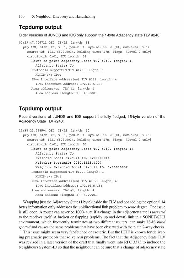
Tcpdump outputOlder versions of JUNOS and IOS only support the 1-byte Adjacency state TLV #240:
00:29:47.706711 OSI, IS-IS, length: 38
p2p IIH, hlen: 20, v: 1, pdu-v: 1, sys-id-len: 6 (0), max-area: 3(0)
source-id: 1921.6809.0034, holding time: 27s, Flags: [Level 2 only]
circuit-id: 0x01, PDU length: 38
Point-to-point Adjacency State TLV #240, length: 1
Adjacency State: Up
Protocols supported TLV #129, length: 1
NLPID(s): IPv4
IPv4 Interface address(es) TLV #132, length: 4
IPv4 interface address: 172.16.5.156
Area address(es) TLV #1, length: 4
Area address (length: 3): 49.0001
Tcpdump outputRecent versions of JUNOS and IOS support the fully fledged, 15-byte version of theAdjacency State TLV #240:
11:35:23.248504 OSI, IS-IS, length: 50
p2p IIH, hlen: 20, v: 1, pdu-v: 1, sys-id-len: 6 (0), max-area: 3 (0)
source-id: 1921.6809.0034, holding time: 27s, Flags: [Level 2 only]
circuit-id: 0x01, PDU length: 50
Point-to-point Adjacency State TLV #240, length: 15
Adjacency State: Up
Extended Local circuit ID: 0x0000001a
Neighbor SystemID: 2092.1113.4007
Neighbor Extended Local circuit ID: 0x0000005f
Protocols supported TLV #129, length: 1
NLPID(s): IPv4
IPv4 Interface address(es) TLV #132, length: 4
IPv4 interface address: 172.16.5.156
Area address(es) TLV #1, length: 4
Area address (length: 3): 49.0001
Wrapping just the Adjacency State (1 byte) inside the TLV and not adding the optional 14bytes information only addresses the unidirectional link problem to some degree. One issueis still open: A router can never be 100% sure if a change in the adjacency state is targetedto the receiver itself. A broken or flapping (rapidly up and down) link in a SONET/SDHenvironment, which frequently terminates at two different routers, can make IS-IS blindspotted and causes the same problems that have been observed with the plain 2-way checks.
This issue might seem very far-fetched or esoteric. But the IETF is known for deliver-ing pragmatic protocols that solve real problems. The fact that the Adjacency State TLVwas revised in a later version of the draft that finally went into RFC 3373 to include theNeighbours System-ID so that the neighbour can be sure that a change of adjacency state
130 5. Neighbour Discovery and Handshaking
was generated by receipt of the neighbour’s recent Hello message indicates that this wasa real concern. If there was a state change by a neighbour and the Source-ID is not listedin the Neighbor Extended Local Circuit-ID field, then it was certainly not the receipt ofthe router’s Hello change that triggered the state change.
Additionally, there was concern about the size (8 bits) of the Local Circuit-ID field inthe point-to-point Hello message. Modern routers can be configured with literally thou-sands of interfaces (usually logical interfaces, but still interfaces) and so that field neededto be extended. TLV #240 transports 32-bit Local Circuit IDs, which should give anyrouter plenty of Circuit-IDs for the time being. Normally routers insert the local interfaceindex or SNMP index into this field.
Contemporary JUNOS releases support the 15-byte version of TLV #240 only. In IOSyou can control the emission of the 1-byte or 15-byte version using the isis three-way-handshake interface configuration option.
IOS configurationThe ietf option to the isis three-way-handshake configuration command emits the15-byte version of TLV #240. The default parameter is the cisco option which generatesthe one-byte TLV payload.
interface POS4/1
[ … ]
isis three-way-handshake ietf
encapsulation ppp
[ … ]
!
If an implementation follows ISO 10589 by the letter, then the expectation would bethat after a completed 2-way or 3-way check, an adjacency goes into the Up state.However, this may not be the case. Most implementations perform additional checksbefore an adjacency is declared Up.
5.4 Sub-net Checking
IS-IS is often expected to be a true multi-protocol IGP. Because adjacency formation,database synchronization and topology calculation (through SPF) is based on Layer-2information, one would expect that it is entirely decoupled from any network layerdependencies. That assumption does not match the deployed reality. IS-IS routers indeeddo verify that the next-hop the router is announcing is valid. The receiving router checksall occurrences of the Interface Address TLV #132 and also checks it against the list oflocal IP addresses configured on that circuit. Figure 5.15 shows the structure of the IPInterface Address TLV #132 which is a simple list of IP addresses that contains a router’sprimary and secondary IP addresses.
Both IOS and JUNOS verify that there is a common IP sub-net. If there is no commonIP sub-net there is also no viable next-hop that can be entered in a routing table, andtherefore the adjacency is considered invalid and stays in the Down / Initializing state.
Sub-net Checking 131

There is unfortunately no show command in the router CLI that reports a sub-net mis-match. You need to turn on debugging in IOS and tracing in JUNOS to get any indicationthere is something wrong in this regard.
In IOS, a sub-net mismatch can be detected once the isis adj-packets debug isturned on. In JUNOS, the trace option flag list needs to include the error flag.
IOS debug outputFor IOS to detect sub-net mismatches the debug isis adj-packets needs to be turnedon. Additionally you need to run terminal monitor to display the logging output on thevty.
London#debug isis adj-packets
IS-IS Adjacency related packets debugging is on
London#terminal monitor
Oct 26 22:33:11: ISIS-Adj: Sending serial IIH on POS4/1, length 4469
Oct 26 22:33:19: ISIS-Adj: Rec serial IIH from *PPP* (POS4/0),
cir type L1L2, cir id 01, length 1492
Oct 26 22:33:19: ISIS-Adj: No usable IP interface addresses in serial IIH
from POS4/0
JUNOS debug outputFor JUNOS to detect sub-net mismatches the flag error under the proto-cols isistraceoptions {} stanza needs to be configured. The logging messages will then bewritten into the specified IS-IS logfile (isis.log)
hannes@Frankfurt> show log isis.log
Oct 26 22:16:13 trace_on: Tracing to “/var/log/isis.log” started
[ … ]
Oct 26 22:33:43 ISIS L3 periodic xmit to interface so-0/2/2.0
Oct 26 22:33:45 ISIS L3 hello from 1921.6800.1068 interface so-0/2/2.0
absorbed
Oct 26 22:33:45 ISIS ERROR: IIH from 1921.6800.1068 without matching
address, interface so-0/2/2.0
132 5. Neighbour Discovery and Handshaking
TLV Type
TLV Length
IP Address
132
Bytes
1
1
4
4
N * 4
IP Address
FIGURE 5.15. The contents of the Interface Address TLV #132 are matched against the local IPaddress to check if there is a matching sub-net

After the sub-net check is positive, and there are no other configuration mismatches,such as misaligned authentication strings or circuit types and levels, the adjacencyshould go to the Up state.
The transition from Down to Up does not occur immediately after receipt of a valid IIHmessage. There are some intermediate states in between, and there is also some dampinglogic involved, which makes sure that the network is not overwhelmed because of aflappy link. The next section is about the adjacency finite state machine and hold downlogic of adjacencies.
5.5 Finite State Machine
Most routing protocols maintain a finite state machine (FSM) for neighbour manage-ment. The FSM is a graph that describes steady states and the events that enable transi-tions from one state to another. In Figure 5.16 there is a FSM for a 2-way handshake.
The three states are:
• Down• New• Up
A receipt of a valid (level, area and authentication needs to match) IIH transitions fromDown to New and finally to Up. A mismatch of level, area and authentication, or a time-out of interface down events immediately transitions the adjacency from Up to Down.
Two-way adjacencies and hence 2-way state machines are an anachronism (as demon-strated by the previous examples) and are deprecated today. Figure 5.17 shows the FSMfor the 3-way handshake.
Finite State Machine 133
Adj. TimeoutIntf. Downbogus System-IDArea MismatchLevel Mismatch
rcvd IIH
Adj. TimeoutIntf. Downbogus System-IDArea MismatchLevel Mismatch
rcvd IIH
rcvd IIH
UpNew
Down
FIGURE 5.16. The finite state machine for a 2-way adjacency (deprecated)
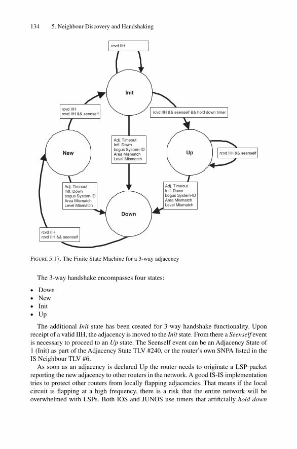
The 3-way handshake encompasses four states:
• Down• New• Init• Up
The additional Init state has been created for 3-way handshake functionality. Uponreceipt of a valid IIH, the adjacency is moved to the Init state. From there a Seenself eventis necessary to proceed to an Up state. The Seenself event can be an Adjacency State of1 (Init) as part of the Adjacency State TLV #240, or the router’s own SNPA listed in theIS Neighbour TLV #6.
As soon as an adjacency is declared Up the router needs to originate a LSP packetreporting the new adjacency to other routers in the network. A good IS-IS implementationtries to protect other routers from locally flapping adjacencies. That means if the localcircuit is flapping at a high frequency, there is a risk that the entire network will be overwhelmed with LSPs. Both IOS and JUNOS use timers that artificially hold down
134 5. Neighbour Discovery and Handshaking
Adj. TimeoutIntf. Downbogus System-IDArea MismatchLevel Mismatch
rcvd IIH && seenself
rcvd IIHrcvd IIH && seenself
rcvd IIH && seenself && hold down timer
Adj. TimeoutIntf. Downbogus System-IDArea MismatchLevel Mismatch
Adj. TimeoutIntf. Downbogus System-IDArea MismatchLevel Mismatch
rcvd IIHrcvd IIH && seenself
rcvd IIH
Up
Init
Down
New
FIGURE 5.17. The Finite State Machine for a 3-way adjacency

an adjacency that is about to enter the Up state for a limited amount of time. Typicallythose timers are in the range of 1–60 seconds depending on factors such as:
• Flapping history• Amount of LSP traffic• Number of adjacencies per interface
If an adjacency has flapped frequently in the past then it is highly likely that it will flapin the future too. It is safe to hold down adjacencies longer if they have a higher amountof transitions over time. JUNOS does, for example, measure the amount of LSPs that aretransmitted through local interfaces. If the amount of LSPs is higher than one LSP persecond then probably the network is shaky and it is not safe to contribute to further churnby announcing an additional LSP. Finally, a common action is to treat point-to-point orsingle adjacency LAN circuits better than LAN circuits with multiple adjacencies. Theidea behind that is if there are some adjacencies already in the Up state then we are prob-ably in the middle of taking up a big LAN segment and there will be more changes tocome. Waiting a little extra time here does not do a lot of harm but highly reduces thechurn if a big LAN goes down.
For high-resiliency routing, it is imperative how fast the router detects that an adja-cency is Down. In the FSM there are two events for Down transitioning: the adjacencytimeout and interface down event. In the next section there is a short overview about IS-IS neighbour liveliness detection and how that impacts high-resiliency routing.
5.6 Neighbour Liveliness Detection
The Internet has evolved from an academic playground to a business-critical infrastruc-ture. Customers and their Internet service providers are keen to tune the convergencespeed in case a backup circuit has to be engaged. The most dominant element for con-vergence behaviour is neighbour liveliness detection. Today there are several options todetect if a circuit to an adjacent router is still able to deliver packets:
• IGP Hellos• Interface Tracking• LMI Protocol
The two major IS-IS implementations treat all three sources of information equally.
5.6.1 IGP HellosThe historical way of detecting that a neighbour is down is by tracking receipt of a neigh-bour’s Hello packets. That method has two disadvantages. First, on a busy router withmany adjacencies the generation and receipt of hundreds of IIH messages may over-whelm the routing process. Second, many routing protocols do not support sub-secondtimers. Consider Figure 5.4, which displays a point-to-point IIH header. The Hold Timefield is a discrete 16-bit field which supports timer values from 1–65535 seconds, but nosub-second timers. The same problem applies to the OSPF routing protocol: The Hello
Neighbour Liveliness Detection 135

136 5. Neighbour Discovery and Handshaking
and Dead timer there needs to be conveyed in the protocol. The lowest unit are onceagain seconds. One of the nice things about IS-IS has been that the Hello timer does notneed to get encoded on the Hello message. The Hello timer is a purely local matter. Thetimer that gets transported using the IS-IS protocol is the hold timer which can go downto 1 second. The Hello timer is therefore a fraction of the hold timer.
In IOS and JUNOS sub-second Hello timers are configured differently: IOS needs the keyword isis hello-interval minimal in its interface configuration.Depending on the isis-hello-multiplier value, IOS dispatches Hellos in frac-tions of this value.
IOS configurationinterface POS4/1
[ … ]
ip router isis
encapsulation ppp
[ … ]
isis hello-multiplier 5 level-1
isis hello-interval minimal level-1
!
Unfortunately, IS-IS has no show command to display its sub-second timers. The fol-lowing Tcpdump output monitors the arrival times of the point-to-point IIH messages.Note that they are all spaced within 200 ms � a random jitter.
Tcpdump output19:15:15.246711 In OSI IS-IS, p2p IIH, length: 4469
19:15:15.440708 In OSI IS-IS, p2p IIH, length: 4469
19:15:15.700683 In OSI IS-IS, p2p IIH, length: 4469
19:15:15.896695 In OSI IS-IS, p2p IIH, length: 4469
19:15:15.1082736 In OSI IS-IS, p2p IIH, length: 4469
In JUNOS, all you can configure is the hold timer. Set it to 1 second and the systemdispatches Hellos at the hold-timer/3 frequency. Note that on point-to-point media youneed to configure the hold-time to the same value on both IS-IS levels otherwise the sys-tem will use the default hold-time values of 27 seconds. The reason for this behaviour isthe sharing of the Hello message between both levels.
JUNOS configurationprotocols {
isis {
[ … ]
interface so-0/1/2.0 {
level 1 hold-time 1;
level 2 hold-time 1;
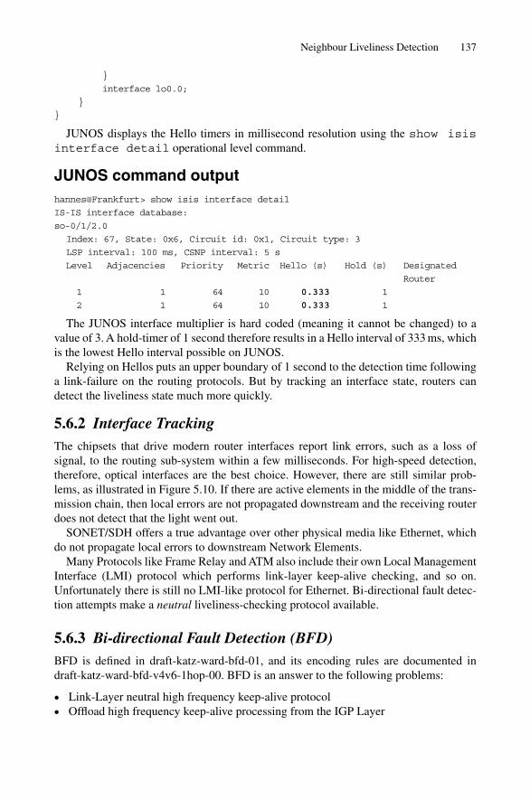
}
interface lo0.0;
}
}
JUNOS displays the Hello timers in millisecond resolution using the show isisinterface detail operational level command.
JUNOS command outputhannes@Frankfurt> show isis interface detail
IS-IS interface database:
so-0/1/2.0
Index: 67, State: 0x6, Circuit id: 0x1, Circuit type: 3
LSP interval: 100 ms, CSNP interval: 5 s
Level Adjacencies Priority Metric Hello (s) Hold (s) Designated
Router
1 1 64 10 0.333 1
2 1 64 10 0.333 1
The JUNOS interface multiplier is hard coded (meaning it cannot be changed) to avalue of 3. A hold-timer of 1 second therefore results in a Hello interval of 333 ms, whichis the lowest Hello interval possible on JUNOS.
Relying on Hellos puts an upper boundary of 1 second to the detection time followinga link-failure on the routing protocols. But by tracking an interface state, routers candetect the liveliness state much more quickly.
5.6.2 Interface TrackingThe chipsets that drive modern router interfaces report link errors, such as a loss of signal, to the routing sub-system within a few milliseconds. For high-speed detection,therefore, optical interfaces are the best choice. However, there are still similar prob-lems, as illustrated in Figure 5.10. If there are active elements in the middle of the trans-mission chain, then local errors are not propagated downstream and the receiving routerdoes not detect that the light went out.
SONET/SDH offers a true advantage over other physical media like Ethernet, whichdo not propagate local errors to downstream Network Elements.
Many Protocols like Frame Relay and ATM also include their own Local ManagementInterface (LMI) protocol which performs link-layer keep-alive checking, and so on.Unfortunately there is still no LMI-like protocol for Ethernet. Bi-directional fault detec-tion attempts make a neutral liveliness-checking protocol available.
5.6.3 Bi-directional Fault Detection (BFD)BFD is defined in draft-katz-ward-bfd-01, and its encoding rules are documented indraft-katz-ward-bfd-v4v6-1hop-00. BFD is an answer to the following problems:
• Link-Layer neutral high frequency keep-alive protocol• Offload high frequency keep-alive processing from the IGP Layer
Neighbour Liveliness Detection 137
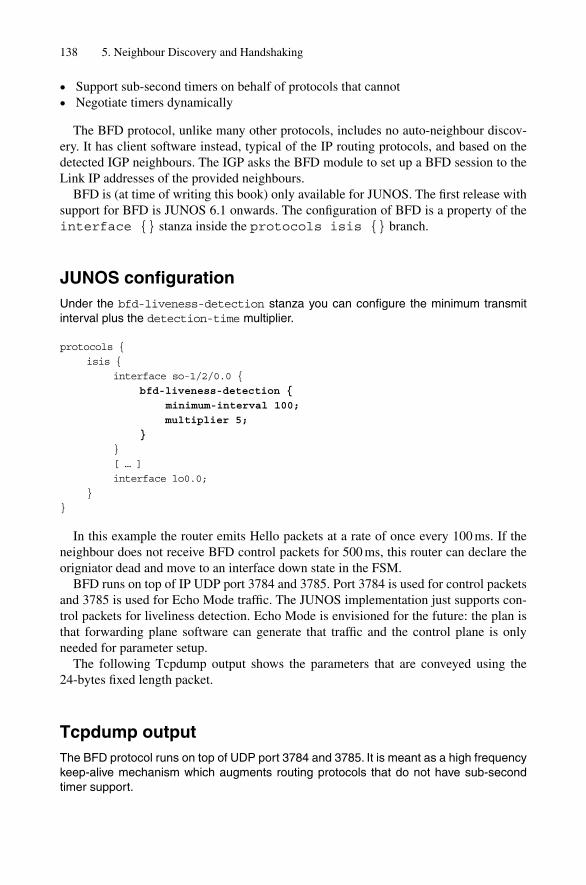
138 5. Neighbour Discovery and Handshaking
• Support sub-second timers on behalf of protocols that cannot• Negotiate timers dynamically
The BFD protocol, unlike many other protocols, includes no auto-neighbour discov-ery. It has client software instead, typical of the IP routing protocols, and based on thedetected IGP neighbours. The IGP asks the BFD module to set up a BFD session to theLink IP addresses of the provided neighbours.
BFD is (at time of writing this book) only available for JUNOS. The first release withsupport for BFD is JUNOS 6.1 onwards. The configuration of BFD is a property of theinterface {} stanza inside the protocols isis {} branch.
JUNOS configurationUnder the bfd-liveness-detection stanza you can configure the minimum transmitinterval plus the detection-time multiplier.
protocols {
isis {
interface so-1/2/0.0 {
bfd-liveness-detection {
minimum-interval 100;
multiplier 5;
}
}
[ … ]
interface lo0.0;
}
}
In this example the router emits Hello packets at a rate of once every 100 ms. If theneighbour does not receive BFD control packets for 500 ms, this router can declare theorigniator dead and move to an interface down state in the FSM.
BFD runs on top of IP UDP port 3784 and 3785. Port 3784 is used for control packetsand 3785 is used for Echo Mode traffic. The JUNOS implementation just supports con-trol packets for liveliness detection. Echo Mode is envisioned for the future: the plan isthat forwarding plane software can generate that traffic and the control plane is onlyneeded for parameter setup.
The following Tcpdump output shows the parameters that are conveyed using the 24-bytes fixed length packet.
Tcpdump outputThe BFD protocol runs on top of UDP port 3784 and 3785. It is meant as a high frequencykeep-alive mechanism which augments routing protocols that do not have sub-secondtimer support.

09:32:30.884968 IP 172.16.223.236.3784 > 172.16.223.235.3784: BFDv0,
length: 24
Control, Flags: [I Hear You], Diagnostic: Control Detection
Time Expired (0x01)
Detection Timer Multiplier: 5 (500 ms Detection time),
BFD Length: 24
My Discriminator: 0x00000001, Your Discriminator: 0x00000002
Desired min Tx Interval: 100 ms
Required min Rx Interval: 200 ms
Required min Echo Interval: 0 ms
Session state transactions are provided using the Flag contents. The Desired/Required Timer Fields are used for negotiating a common timer that both peers canaccept. The pair of discriminators is necessary to multiplex several sessions between apair of hosts.
After BFD has been enabled on both sides, one can verify if a BFD-capable neighbourhas been found on the other end and if the BFD session is Up. The show bfd ses-sion command displays the session state.
JUNOS command outputUsing the show bfd session command you can display the current state and details ofthe active BFD sessions.
hannes@Frankfurt> show bfd session extensive
Transmit
Address State Interface Detect Time Interval Multiplier
172.16.223.236 Up so-0/1/2.0 1.000 0.100 5
Client ISIS L1, TX interval 0.100, RX interval 0.100, multiplier 5
Client ISIS L2, TX interval 0.100, RX interval 0.100, multiplier 5
Session up time 12:34:22, previous down time 00:00:06
Local diagnostic CtlExpire, remote diagnostic None
Remote heard, hears us
Min async interval 0.100, min slow interval 1.000
Adaptive async tx interval 0.100, rx interval 0.200
Local min tx interval 0.100, min rx interval 0.100, multiplier 5
Remote min tx interval 0.100, min rx interval 0.100, multiplier 5
Local discriminator 1, remote discriminator 2
Echo mode disabled/inactive
1 sessions, 2 clients
Cumulative transmit rate 10.0 pps, cumulative receive rate 5.0 pps
BFD is likely to become the dominant keep-alive protocol due its open implemen-tation. It is expected to even be the protocol of choice between routers and servers. For server applications like voice-over IP or financial applications there are open-sourceBFD implementations for hosts available.
Neighbour Liveliness Detection 139

5.7 Summary
IS-IS adjacency processing has changed over the years. It started out with simple 2-wayfinite state machines and, due to the underlying problems of not detecting half-brokenlinks, it quickly evolved to a 3-way FSM. It is remarkable that the defects of the under-lying protocol have been solved with just the addition of an optional Adjacency StateTLV. Reliably detecting that a neighbour is Up or Down is not enough for today’s ser-vice provider environments. On the one hand the implementation has to be slow enoughto protect the network from flapping adjacencies that are propagated through the network –on the other hand there is a need for quick keep-alive detection mechanisms. Due to therise of Ethernet as popular core-facing interface technology, an LMI-like protocol likeBi-directional Fault Detection (BFD) had to be designed. The application of BFD toserve as an IGP detection protocol is just the start. It is expected that BFD will be usedfor other network protocols or other environments like application keep-alive detectionfor mission-critical servers.
140 5. Neighbour Discovery and Handshaking

6
Generating, Flooding and Ageing LSPs
141
Unlike distance vector protocols, such as RIP, link-state routing protocols, such as OSPFand IS-IS, don’t tell only their neighbours about the topology of the network. Link-stateprotocols distribute both their IP reachability and topological view far beyond their adja-cent neighbours, ultimately flooding this information to all routers in an area.
To keep the reachability information in the network current, link-state protocols needto have a basic set of functions available that can be used to originate, distribute andfinally revoke, or time-out topology information. In IS-IS-speak, that piece of topologyinformation is encoded in a link-state protocol data unit (LSP). This chapter covers thesefunctions and the surrounding network events th at cause the IS-IS protocol to generate,flood and finally age LSPs.
Link-state routing protocols such as IS-IS follow a paradigm that can best be describedas distributed databases with local computation, which is quite different to the way othercommon routing protocols like RIP and BGP work. Distributed databases are discussedin more detail in the following section.
6.1 Distributed Databases
Before explaining how a distributed database works, first consider what a localized data-base looks like and how routing protocols use it. Localized databases mean that everyrouter has its own local view of the network and does not know the exact topology of thenetwork as a whole. This is like a tourist in a foreign city having no clue about what theoverall topology of the city (the street layout) looks like. All the tourist has is a local viewof the places and streets that are next to the tourist’s immediate location. This makes itvery difficult to find the best path to a landmark or museum, and in the worst case situation,the tourist has to try out several paths, being careful not to circle around the same locations.Localized databases work the same way. In contrast, a distributed database approachworks differently: here all of the routers share common information about what the networklooks like. If the tourist in the example has got lost, a distributed database map would givethem a more complete map of the best way to get to a particular destination in the city (orin this case, the network).
How does IS-IS compute the map of the network? If each router just contributes itslocal view to its neighbours, and if that information can be shared among all the routersin a network, then each will ultimately have a global map of the network. Link-state rout-ing protocols, such as IS-IS, work like a jigsaw puzzle, as shown in Figure 6.1. Eachrouter in the figure represents one piece of the puzzle, and if all of the puzzle pieces arepresent, then each router can start to put the puzzle together to acquire an understanding
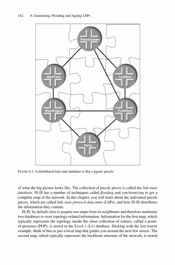
of what the big picture looks like. The collection of puzzle pieces is called the link-statedatabase. IS-IS has a number of techniques called flooding and synchronizing to get acomplete map of the network. In this chapter, you will learn about the individual puzzlepieces, which are called link-state protocol data units (LSPs), and how IS-IS distributesthe information they contain.
IS-IS, by default, tries to acquire two maps from its neighbours and therefore maintainstwo databases to store topology-related information. Information for the first map, whichtypically represents the topology inside the close collection of routers, called a point-of-presence (POP), is stored in the Level 1 (L1) database. Sticking with the lost touristexample, think of this as just a local map that guides you around the next few streets. Thesecond map, which typically represents the backbone structure of the network, is stored
142 6. Generating, Flooding and Ageing LSPs
Pennsauken
Frankfurt
London
Washington
NewYork
Paris
FIGURE 6.1. A distributed link-state database is like a jigsaw puzzle

Distributed Databases 143
in the Level 2 (L2) database. This would best compare to a nationwide map where all thefreeways and highways are shown. You can take a quick look into both of these link-statedatabases to find out exactly which puzzle pieces the database holds by issuing a showisis database command on both the IOS and JUNOS software platforms.
IOS command outputThe contents of the IS-IS link-state database can be displayed using the show isisdatabase command:
Amsterdam# show isis database
[ … ]
IS-IS Level-1 Link State Database:
LSPID LSP Seq Num LSP Checksum LSP Holdtime ATT/P/OL
New-York.00-00 0x00002fac 0xC24F 60128 1/0/0
[ … ]
IS-IS Level-2 Link State Database:
LSPID LSP Seq Num LSP Checksum LSP Holdtime ATT/P/OL
LINX-gw.00-00 0x00000128 0xB8EF 36163 0/0/1
LINX-gw.01-00 0x00000128 0x455A 42001 0/0/0
VIX-gw.00-00 0x00000123 0xEFC1 5023 0/0/0
[ … ]
The output shows you one “puzzle piece” of information in each line. Each LSP isuniquely identified by its LSP-ID. The exact format of the LSP-ID will be discussed laterin this chapter. All that is important for now is that it says something about the router thatoriginated that LSP. The sequence number is a kind of version field that tells receiverswhich information is more recent. The checksum enables to check at the receiver if theLSP has been corrupted during its long way through the network. Finally, hold-time andthe ATT/P/OL gives some information about the validity of that information and howlong it will be valid, and just like a passport it has an expiration date.
JUNOS command outputIn the JUNOS software, you can display the IS-IS database using the show isis data-base command. Watch for an inconsistency between the LSPs being sent and received,as this is a problem indication:
hannes@New-York> show isis database
IS-IS level 1 link-state database:
LSP ID Sequence Checksum Lifetime Attributes
New-York.00-00 0x2fac 0xc24f 62063 L1 Attached
[ … ]
4 LSPs
IS-IS level 2 link-state database:
LSP ID Sequence Checksum Lifetime Attributes
LINX-gw.00-00 0x128 0xb8ef 36063 L1 L2 Overload
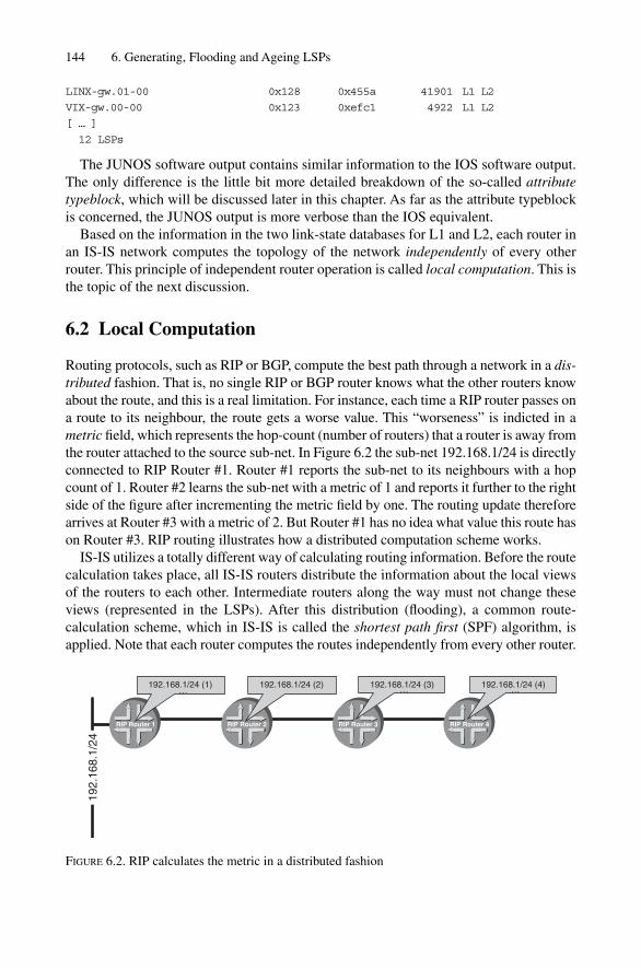
LINX-gw.01-00 0x128 0x455a 41901 L1 L2
VIX-gw.00-00 0x123 0xefc1 4922 L1 L2
[ … ]
12 LSPs
The JUNOS software output contains similar information to the IOS software output.The only difference is the little bit more detailed breakdown of the so-called attributetypeblock, which will be discussed later in this chapter. As far as the attribute typeblockis concerned, the JUNOS output is more verbose than the IOS equivalent.
Based on the information in the two link-state databases for L1 and L2, each router inan IS-IS network computes the topology of the network independently of every otherrouter. This principle of independent router operation is called local computation. This isthe topic of the next discussion.
6.2 Local Computation
Routing protocols, such as RIP or BGP, compute the best path through a network in a dis-tributed fashion. That is, no single RIP or BGP router knows what the other routers knowabout the route, and this is a real limitation. For instance, each time a RIP router passes ona route to its neighbour, the route gets a worse value. This “worseness” is indicted in ametric field, which represents the hop-count (number of routers) that a router is away fromthe router attached to the source sub-net. In Figure 6.2 the sub-net 192.168.1/24 is directlyconnected to RIP Router #1. Router #1 reports the sub-net to its neighbours with a hopcount of 1. Router #2 learns the sub-net with a metric of 1 and reports it further to the rightside of the figure after incrementing the metric field by one. The routing update thereforearrives at Router #3 with a metric of 2. But Router #1 has no idea what value this route hason Router #3. RIP routing illustrates how a distributed computation scheme works.
IS-IS utilizes a totally different way of calculating routing information. Before the routecalculation takes place, all IS-IS routers distribute the information about the local viewsof the routers to each other. Intermediate routers along the way must not change theseviews (represented in the LSPs). After this distribution (flooding), a common route-calculation scheme, which in IS-IS is called the shortest path first (SPF) algorithm, isapplied. Note that each router computes the routes independently from every other router.
144 6. Generating, Flooding and Ageing LSPs
192.
168.
1/24
…
RIP Router 1 RIP Router 2 RIP Router 3 RIP Router 4
192.168.1/24 (1) 192.168.1/24 (2) 192.168.1/24 (3)…
192.168.1/24 (4)……
FIGURE 6.2. RIP calculates the metric in a distributed fashion

Local Computation 145
You can watch the result of the SPF calculation by issuing a show ip route isis com-mand on IOS platforms and a show isis route command on Juniper Network routers.
In IOS, you cannot see the entire results of the SPF calculation – all you can see arethe results that make it into the main routing table. That excludes redundant routers thathappen to be in both IS-IS levels. The IS-IS learned routes that are active in the routingtable can be displayed using the show ip route isis command.
IOS command outputAmsterdam#show ip route isis
[ … ]
i L1 192.168.0.55 [115/10] via 172.16.144.2, POS3/0
i L1 192.168.0.57 [115/10] via 172.16.144.2, POS4/0
i L2 192.168.1.122 [115/10] via 172.16.177.18, GigabitEthernet3/0
[ … ]
The output tells us basically what routes (second column) did get installed in the localrouting and forwarding tables. Each line contains information about a single route. Thefirst column shows the level. The numbers in the brackets after the route give informa-tion about the weight or, as it is called in Cisco IOS speak, the administrative distance ofthe routing protocol that inserted this route into the routing table (in this case, IS-IS).After the “via” statement the IP address of a locally connected router appears (the next-hop). Finally the end of each line gives the physical interface through which the next-hopcan be reached and this is how packets to this destination will leave the router.
In the JUNOS software, you can display both the immediate results from the SPF calcu-lation as well as the routes installed in the routing table. The SPF results are displayed usingthe show isis route command. The IS-IS learned routes that are active in the mainrouting table can be displayed using the show route protocol isis command.
JUNOS software command outputhannes@Pennsauken> show isis route
IS-IS routing table Current version:L1: 0 L2: 485
Prefix L Version Metric Type Interface Via
172.16.44.248/30 2 485 61770 int so-3/0/0.0 London
192.168.49.5/32 2 485 67850 int so-3/0/0.0 London
192.168.49.67/32 2 485 67860 int so-3/0/0.0 London
192.168.52.177/32 2 485 127850 int so-3/0/0.0 Frankfurt
192.168.54.164/32 2 485 128510 int so-3/0/0.0 Frankfurt
172.16.176.0/24 2 485 121770 int so-3/0/0.0 Frankfurt
172.16.176.32/30 2 485 127830 int so-3/0/0.0 New-York
172.16.176.60/30 2 485 123790 int so-3/0/0.0 New-York
[ … ]
The format of the output is one route entry per line. The first column contains the routeand the second column contains information about the level where this route did resultfrom. The version field is just an internal number that tells you how the SPF run number
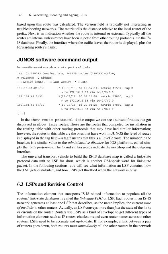
based upon this route was calculated. The version field is typically not interesting in troubleshooting networks. The metric tells the distance relative to the local router of theprefix. Next is an indication whether the route is internal or external. Typically all theroutes are internal unless routes have been injected from other routing protocols into the IS-IS database. Finally, the interface where the traffic leaves the router is displayed, plus theforwarding router’s name.
JUNOS software command outputhannes@Pennsauken> show route protocol isis
inet.0: 118243 destinations, 246129 routes (118243 active,
0 holddown, 0 hidden)
+ = Active Route, - = Last Active, * = Both
172.16.44.248/30 *[IS-IS/18] 4d 12:57:11, metric 41550, tag 2
> to 172.16.5.93 via so-3/2/0.0
192.168.49.5/32 *[IS-IS/18] 2d 07:26:54, metric 67850, tag 2
> to 172.16.5.93 via so-2/3/0.0
192.168.49.67/32 *[IS-IS/18] 1d 20:01:28, metric 67860, tag 2
> to 172.16.5.93 via so-7/0/0.0
[ … ]
In the show route protocol isis output we can see a subset of routes that gotdisplayed in show isis routes. Those are the routes that competed for installation inthe routing table with other routing protocols that may have had similar information;however, the routes in this table are the ones that have won. In JUNOS the level of routesis displayed in the tag field – a tag 2 means that this is a Level 2 route. The number in thebrackets is a similar value to the administrative distance for IOS platforms, called sim-ply the route preference. The to and via keywords indicate the next-hop and the outgoinginterface.
The universal transport vehicle to build the IS-IS database map is called a link-stateprotocol data unit or LSP for short, which is another OSI-speak word for link-statepacket. In the following sections, you will see what information an LSP contains, howthe LSP gets distributed, and how LSPs get throttled when the network is busy.
6.3 LSPs and Revision Control
The information element that transports IS-IS-related information to populate all therouters’ link-state databases is called the link-state PDU or LSP. Each router in an IS-ISnetwork generates at least one LSP that describes, as the name implies, the current stateof the links to other routers. Actually, an LSP conveys more than just the state of the linksor circuits on the router. Routers use LSPs as a kind of envelope to get different types ofinformation elements such as IP routes, checksums and even router names across to otherrouters. LSPs need to be accurate and up-to-date. If, for example, a link between a pairof routers goes down, both routers must immediately tell the other routers in the network
146 6. Generating, Flooding and Ageing LSPs

that the link is down. The other routers then update their link-state databases, schedulean SPF calculation, and remove that broken link from any transit paths in the networkthat might use the failed link.
Now, assume that a remote router gets two conflicting messages at the same time. Thatis, messages arrive almost at the same time claiming that a link is up and down. ConsiderFigure 6.3. There are three routers connected by point-to-point links. Unfortunately, thelink between Router B and Router C is constantly going down, then up, and a short timelater, it goes down again. In network-speak this a flapping link. Next, assume that RouterB is a busy router with its CPU being loaded close to the ceiling. Therefore, Router B isslower in processing the link-down/link-up events. In addition, the subsequent regener-ation of its LSPs that report the link as down or up to other routers is slower.
Figure 6.4 shows the LSP messages from Router A’s perspective. Both Router B andRouter C find out first that there is a link-up event. However, Router C processes that eventfar faster than the overloaded Router B. The trouble occurs as the link flaps again, this timetransitioning from the Up to the Down state. Router B still did not send the previous LSPout because it was too busy. Router B’s LSP is now outdated information because the linkis now in the Down state. So both LSPs (Router B’s old Up one and Router C’s accurateDown one) arrive at the same time at Router A. Now Router A needs to decide which is themost accurate report – the Up or Down state message. The LSP to use should be the mostrecent one, but in the example the most recent rule would fail because the propagationdelay from Router B to Router A made that inaccurate LSP arrive after Router C’s up-to-date LSP. The conclusion here is that LSPs need to carry some sort of version informationto explicitly tell the receiving router what is current and what is outdated LSP information.
6.3.1 Sequence NumbersLink-state routing protocols carry version information through a Sequence Numbersfield. IS-IS has a linear sequence number space starting from one and counting up. Thatmeans that the first LSP that is announced by a router has the sequence number 0x1.Each time the router issues a new view of the local environment to its neighbours, therouter will package that information in an LSP, increment the sequence number by one,and send the LSP to all of its neighbours. The neighbours compare the incoming LSPwith the LSP in the local database. If the received LSP is new to them (that is, the
LSPs and Revision Control 147
What is the most recentmessage?
Router A
Router B
Router C
FIGURE 6.3. The routers have to find out what is the most recent event

received LSP is not in the local database at all), then they unconditionally install the LSPinto their local link-state database. If the LSP is already installed in the database, thereceiving router needs to check if the sequence number is higher than the sequence num-ber of the LSP that is already installed in the link-state database. If the LSP is newer, thenthe router will flush (or discard) the existing LSP and update the LSP with the morerecent one. If it turns out (like in the previous example) that the most recent arriving LSPis older (has a lower LSP sequence number) then the one installed in the link-state data-base and therefore carries outdated information, the received LSP is silently discarded.As IS-IS is a reliable protocol, the router will of course acknowledge receipt of that LSPto the neighbour that sent it. If not acknowledged, the router will see the LSP again after5 seconds, once the neighbour retransmits it. You can learn more about acknowledgingand retransmission of LSPs in Chapter 8.
The LSP sequence number field is a 32-bit identifier, giving room for about 4 billionLSP updates. LSPs are subject to strict pacing, which means, for example, that a routermust not originate more than one LSP every 5 seconds. 2^32 times 5 seconds results inan interval of 21,474,836,480 seconds, or roughly 681 years. So the sequence numberspace is not likely to get to its end, at least not until readers are retired, which is typicallythe timeframe that engineers care about.
Seriously, it is just assumed that the LSP sequence space will not run out. Assumptionsalways cause a lot of trouble for engineers. The root-cause of the Y2K scare went back to
148 6. Generating, Flooding and Ageing LSPs
“slow”Router B
Router C
tt t
Router A
LSPRouter B
Link Up to Router C
Link “Up”
Link “Down”
Bigprocessing
delay
Bigprocessing
delay
LSPRouter B
Link Down to Router C
LSP
Link Up to Router C
Router C
LSP
Link Down to Router C
Router C
Littleprocessing
delay
Littleprocessing
delay
ConflictingMessageshit Router A
FIGURE 6.4. In distributed environments Router A can get confused if the Link-Up or Link-Downis the most recent event

assumptions about events that should not be a problem but ultimately were. The bottomline is the Y2K problem cost corporate customers a lot of money to sanity check theirapplications and to spot software problems before the millennium turnover. But IS-IS iswell prepared in that respect, since there actually is something that can be done if the LSPsequence number space is ever maxed out. So what does a router do if it wants to originatea new LSP and does hit the ceiling of the LSP sequence space? Now, the assumption isthat this ceiling will never be reached. But even if it finally is, there is a well-defined pro-cedure to handle that event: the router must simply wait for a period of max-age seconds.This sounds odd at first: why does waiting solve anything? And how long does max-agelast? As it turns out, it lasts a Lifetime – an LSP’s Lifetime.
6.3.2 LSP LifetimesIn addition to the revision information (the LSP sequence numbers), link-state protocolsinclude in their LSPs a field called the Lifetime, which helps to control the maximumvalidity span of LSPs. A router announcing an LSP does not mean that the LSP will bevalid forever, only for the number of seconds indicated in the Lifetime field of an LSP.Adding a Lifetime field to the protocol helps to protect against stale (and potentiallywrong) entries in the link-state database. Consider a scenario where a router is taken outof the network by being powered down. The LSP(s) of that powered-down router is or arestill installed in the link-state database of all the routers in the network. If the originatingrouter did not revoke or purge them (you will see shortly how this works), the LSPs wouldstay in the link-state database forever. The Lifetime field in the LSP is a 16-bit entity,which means that the Lifetime field can be set as high as 2^16-1 or in decimal notation65,535 seconds, or a little over 18 hours.
The Lifetime field provides an answer to the unlikely event of IS-IS LSP sequence num-ber space exhaustion. Before an IS-IS router can generate a new LSP with a sequencenumber of 1, the router must wait until the Lifetimes of all previous LSPs it has generatedhas expired and the LSPs have disappeared from all other routers’ link-state databases.At most, this wait (max-age) will be 18 hours. This sounds very high, but waiting 18 hoursevery 681 years should not be much of a problem for a network. And in practice, IS-ISimplementations only use the maximum 18-hour Lifetime when extreme backgroundflooding silence is needed. Most of the time, IS-IS uses the default Lifetime value of1200 seconds (20 minutes). This value can be changed in most IS-IS implementations,and often it is changed. But what stops every LSP from disappearing from the networkevery 20 minutes? A periodic LSP refresh.
6.3.3 Periodic RefreshesLSPs with maximum Lifetimes have the consequence that LSPs need to get refreshed.Refreshing means that a router has to re-originate its LSPs periodically. The re-originationinterval has, of course, to be less than the LSP’s Lifetime. For example, if the LSP isvalid for 1200 seconds (the default value), the router needs to refresh the LSP in less than1200 seconds in order to avoid removal of the LSP from the link-state database by other
LSPs and Revision Control 149

routers. The recommended max-LSP-origination-interval is the Lifetime minus 300 sec-onds. So in a default environment this would be 900 seconds.
Figure 6.5 shows in a timing diagram how and when a router refreshes its LSPs. Every900 seconds an LSP with the same information content is created. Here, Router A alwaysreports that the router has links in the Up state to Router B and C. Please note that foreach refresh, the Sequence Number is incremented by one (bumped). Each time that LSPis refreshed, the Lifetime gets prolonged for another N seconds, as described in theLifetime field (the default value is 1200 seconds).
Both Cisco IOS and JUNOS software do originate all LSPs with a default Lifetime of1200 seconds, as suggested in the ISO 10589 specification. However, you can changethis to higher values to reduce the amount of refreshes in the network (the refresh timeris seldom made a lower value). Often theses periodic LSP refreshes are called refreshnoise, and network administrators want to reduce this noise close to zero. Both CiscoIOS and JUNOS software offer configuration knobs to change the maximum Lifetime oftheir LSPs and at the same time the re-origination interval derived from this value. IOSlets you define the Lifetime and refresh intervals independently from each other. All youhave to make sure of is that the max-lsp-lifetime be a few hundred seconds higherthan the lsp-refresh-interval. If you modify the max-lsp-lifetime donot forget to set the lsp-refresh-interval accordingly (a few hundred secondslower than max-lsp-lifetime). If you forget to set the refresh interval, then theLSPs will get refreshed according to the default timer, which is 900 seconds. This willnot break anything but it also does not help to reduce the refresh noise. The outcomemight be an LSP originated with the maximum Lifetime of 65,535 seconds which willstill be refreshed each 900 seconds.
In IOS you can set the LSPs Lifetime and refresh interval independently from eachother, as shown in the following (note the bolded sections in this code listing).
IOS configurationIn IOS the max-lsp-lifetime and lsp-refresh-interval parameters need to be atleast 300 s apart.
Amsterdam# show running-config
[ … ]
router isis
max-lsp-lifetime 65535
lsp-refresh-interval 65000
[ … ]
The JUNOS software only exposes the lsp-lifetime knob to the user interface.The developers at Juniper Networks feared that inconsistent setting of Lifetime andrefresh interval might mess things up seriously. As an example, think about what mighthappen if the Lifetime is set to be smaller than the refresh interval. The refresh intervalis calculated automatically. The refresh interval in a Juniper Networks router is the LSPLifetime minus 317 seconds.
150 6. Generating, Flooding and Ageing LSPs

151
LS
PR
ou
ter
A, S
equ
ence
0x4
Lif
etim
e 12
00s
LS
P
Lin
k U
p t
o R
ou
ter
C
Lin
k U
p t
o R
ou
ter
B
Ro
ute
r A
, Seq
uen
ce
0x3
Lif
etim
e 12
00s
LS
P
Lin
k U
p t
o R
ou
ter
C
Lin
k U
p t
o R
ou
ter
B
Ro
ute
r A
, Seq
uen
ce
0x2
Lif
etim
e 12
00s
1000
2000
3000
0
LS
P
Lin
k U
p t
o R
ou
ter
CL
ink
Up
to
Ro
ute
r B
Ro
ute
r A
, Seq
uen
ce
0x1
Lif
etim
e 12
00s
Per
iodi
c re
fres
hes
bum
p th
e S
eque
nce
Num
ber
ever
y 90
0 se
cond
s
t(s)
max
LS
P li
fetim
e 12
00s
max
LS
P li
fetim
e 12
00s
max
LS
P li
fetim
e 12
00s
max
LS
P li
fetim
e 12
00s
Lin
k U
p t
o R
ou
ter
C
Lin
k U
p t
o R
ou
ter
B
FIG
UR
E6.
5. P
erio
dic
refr
eshe
s

In the JUNOS software, the refresh interval is automatically calculated as the LSP refreshinterval equal to the Lifetime minus 317 seconds. In the following listing, the relevantJUNOS software configuration is marked in bold:
JUNOS configurationhannes@New-York> show configuration
[ … ]
protocols {
isis {
lsp-lifetime 65535;
interface lo0.0;
interface so-0/0/0;
}
}
[ … ]
As we can control how long an individual LSP will last (given that there is no changein the network) we will unveil how an LSP actually looks and what particular informa-tion it contains.
6.3.4 Link-state PDUsFigure 6.6 shows the structure of a link-state PDU. In the common header, the Lengthfield is fixed to 27 bytes. The code points for the PDU type are 18 for Level 1 LSPs and20 for Level 2 LSPs. The common LSP header contains the PDU length, which is theaggregate length of the IS-IS PDU excluding Layer 2 information (such as PPP, Cisco-HDLC, and MAC addresses). In the LSP header, the four most important elements are:
• Lifetime• LSP-ID• Sequence Number• Checksum
The purpose of the Sequence Number and Lifetime fields was already discussed in theprevious sections. The 16-bit Checksum field contains an international standard X.233Fletcher Checksum. The Fletcher Checksum is a simple checksum algorithm that, in add-ition to protecting the payload of the LSP, ensures that there is no imbalance between zerosand ones in the resulting checksum. Checksums generally help to make bit errors introducedby WAN transmission more recognizable by the receiver. You can learn more aboutchecksums and what particular problems they solve in Chapter 13, which gives a goodoverview of IS-IS checksumming, failure scenarios, and checksumming related defects.
The LSP-ID field determines the LSP type. Figure 6.7 shows the structure of the LSP-ID field. The LSP-ID is a fixed 8-byte field. The first 6 bytes are set to the System-ID ofthe LSP Originator. The System-ID has the purpose of uniquely identifying a router inthe IS-IS network. If you are familiar with OSPF, the System-ID can best be comparedwith the Router-ID. The only difference is that OSPF Router IDs are 32-bits (4 bytes)
152 6. Generating, Flooding and Ageing LSPs
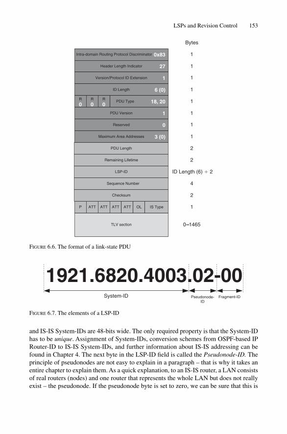
and IS-IS System-IDs are 48-bits wide. The only required property is that the System-IDhas to be unique. Assignment of System-IDs, conversion schemes from OSPF-based IPRouter-ID to IS-IS System-IDs, and further information about IS-IS addressing can befound in Chapter 4. The next byte in the LSP-ID field is called the Pseudonode-ID. Theprinciple of pseudonodes are not easy to explain in a paragraph – that is why it takes anentire chapter to explain them. As a quick explanation, to an IS-IS router, a LAN consistsof real routers (nodes) and one router that represents the whole LAN but does not reallyexist – the pseudonode. If the pseudonode byte is set to zero, we can be sure that this is
LSPs and Revision Control 153
Intra-domain Routing Protocol Discriminator
Header Length Indicator
Version/Protocol ID Extension
0x83
Bytes
1
1
1
1
1
1
1
1
1
ID Length
PDU TypeR
0R
0R
0
PDU Version
Reserved
Maximum Area Addresses
6 (0)
1
3 (0)
0
TLV section 0–1465
18, 20
27
Remaining Lifetime
LSP-ID
PDU Length
Sequence Number
2
2
ID Length (6) � 2
4
Checksum 2
P 1ATT ATT ATT ATT OL IS Type
FIGURE 6.6. The format of a link-state PDU
1921.6820.4003.02-00System-ID Pseudonode-
IDFragment-ID
FIGURE 6.7. The elements of a LSP-ID

a real router. If the pseudonode byte is non-zero then it represents the whole LAN . InIS-IS LANs are represented in the link-state database with a unique identifier. Moreinformation about pseudonodes and why they make sense is presented in Chapter 7.
The last byte in the LSP-ID field is called the Fragment ID. IS-IS runs directly on topof OSI-RM Layer 2, which does not have a built-in fragmentation function for larger-than-MTU-sized packets. IP-based routing protocols, such as OSPF, rely on IP to pro-vide this fragmentation service, but IS-IS is not IP-based. So IS-IS needs to supportfragmentation through the application itself: IS-IS. Once again, IS-IS fragmentation isworth a chapter on its own, because there are lots of interesting issues surrounding IS-ISfragmentation such as “What should be done if a fragment of an LSP is missing”, “Isthere a special meaning to fragment zero”, and “What should be done if the fragmentspace itself is exhausted?” Chapter 9 is dedicated to giving answers to these and otherquestions surrounding fragmentation.
LSP-IDs are not displayed as a string of 8 consecutive bytes. In modern routing soft-ware LSP-IDs follow certain conventions. In the next paragraphs the notation of LSP-IDs will briefly be discussed. Furthermore we spot on more detailed what bits theAttribute Type Block contains and what particular Application of the Overload Bitmay be.
6.3.4.1 LSP Notation
Typically the LSP-ID is displayed in the following format:
xxxx.xxxx.xxxx.yy-zz
Here, an x stands for the System-ID digits, y stands for the Pseudonode-ID, and z rep-resents the fragment number. Let’s have a look at a tcpdump showing an LSP header andits contents. The following shows a real-world LSP. Look especially at the notation usedfor the LSP. The fields of the LSP header are shown in bold:
Tcpdump output11:36:45.587565 OSI, IS-IS, length: 405
L2 LSP, hlen: 27, v: 1, pdu-v: 1, sys-id-len: 6 (0), max-area: 3 (0)
lsp-id: 1921.6800.0012.00-00, seq: 0x000002fd, lifetime: 1198s
chksum: 0xe984 (correct), PDU length: 405, Flags: [ L1L2 IS ]
Authentication TLV #10, length: 7
simple text password: !$xyz00
Area address(es) TLV #1, length: 4
Area address (3): 49.0001
Protocols supported TLV #129, length: 1
NLPID(s): IPv4 (0xcc)
Hostname TLV #137, length: 6
Hostname: London
IPv4 Interface address(es) TLV #132, length: 4
IPv4 interface address: 172.16.1.33
154 6. Generating, Flooding and Ageing LSPs

IPv4 Internal Reachability TLV #128, length: 84
IPv4 prefix: 10.254.47.8/30, Distribution: up, Metric: 5, Internal
IPv4 prefix: 10.252.1.0/30, Distribution: up, Metric: 5, Internal
IPv4 prefix: 10.254.1.48/30, Distribution: up, Metric: 1, Internal
IPv4 prefix: 10.254.1.20/30, Distribution: up, Metric: 5, Internal
IPv4 prefix: 10.254.3.4/30, Distribution: up, Metric: 25, Internal
IPv4 prefix: 10.254.1.72/30, Distribution: up, Metric: 2, Internal
IPv4 prefix: 10.254.1.28/30, Distribution: up, Metric: 5, Internal
Extended IS Reachability TLV #22, length: 75
IS Neighbor: 1921.6800.1001.00, Metric: 5, sub-TLVs present (64)
IPv4 interface address subTLV #6, length: 4, 10.154.1.6
IPv4 neighbor address subTLV #8, length: 4, 10.154.1.5
Unreserved bandwidth subTLV #11, length: 32
The first output of the second line shows us an LSP-ID. We recognize that this is anLSP-ID because it follows the xxxx.xxxx.xxx.yy-zz style. Only LSP-IDs follow thatstyle. The last bold argument in the tcpdump output shows the so-called Attribute TypeBlock, which has in the example two bits set.
6.3.4.2 Attribute Block
What are the Flags [ L1L2 IS] following the checksum? What are they used for? The lastbyte in the LSP header is often referred to as the attribute block. These 8 bits tell thereceiver crucial information about the nature of the LSP. These 8 bits are:
• Bit 8 – P (Partition Repair) Bit• Bit 7 – ATT-Error Bit• Bit 6 – ATT-Expense Bit• Bit 5 – ATT-Delay Bit• Bit 4 – ATT-Default Bit• Bit 3 – OL (Overload) Bit• Bit 2 and 1 – IS Type Bits
The P (Partition Repair) Bit is what is known as a capability indicator that shows if theissuing router supports the partition repair functionality (that is, this bit indicates thatcapability). Partition repair means that a broken Level 1 area can be healed through theLevel 2 IS-IS routers. It is not possible to be very specific here because Partition Repairis barely deployed and sometimes even not supported in certain IS-IS implementationssuch as JUNOS. Partition repair is left as an option to the implementer of the protocol,so this is not a major issue. Typically, if a specification says that something is optional,and if it is complicated to implement or does not solve a specific problem, this is enoughjustification to ignore that function entirely. So if you take the time and crawl throughprotocol specification, such as RFCs and Internet drafts or – even worse – ISO papersand documents, then you almost always can replace the word “should” with “can-be-ignored” in your mind.
LSPs and Revision Control 155

The next four bits in the Attribute block, Bits 7 to 4, determine if the issuing Intermediate System is attached to another area or not. Only L1L2 routers may set thisbit in their Level-1 LSPs. But why are there 4 bits denoted to this functionality, and notjust one? Because at the time when ISO 10589 was specified (in the late 1980s) manypeople believed that routing protocols should support multiple topology databases, eachset up for a particular purpose. The original idea was that IS-IS should calculate onetopology database that would have the lowest bit error rate, one topology database for the least expensive paths in the network, one that reflects the lowest delay topology,and finally one that would be used if the sender of the packet were undecided which of the topologies to pick. This is an early form of Class-of-Service (CoS) enabled routing, which ultimately did not get deployed because network engineers felt uncom-fortable (rightly so at the time) about supporting such multidimensional networks. Bits5, 6 and 7 therefore got deprecated (not quite obsolete, but not promoted at all) over time.Today, as far as IP routing is concerned both JUNOS and IOS only support the default-metric, and hence just the bit 4 default topology, which only demands a single instanceof SPF calculation. There are more places in the IS-IS specification where this CoS-based routing legacy pops up; however, in modern routing it has been entirely deprecated.
The Overload Bit is used (not surprisingly) to indicate that a router is in an overloadedcondition. Initially, this was envisioned to serve as an indicator that a router had run out of memory. Running out of memory in a router is never good, but the impact of memory shortage is especially dramatic for link-state protocols: if a router cannot storeall LSPs in its link-state database the router will not be able to calculate loop-free paths through the network. The idea behind the Overload Bit is that once the routernotices that it is running short of memory, the router will simply refuse to play SPF withneighbours and pull itself out of the game. A router holding half of the informationneeded for proper SPF calculations, and disturbing the other routers by advertising this half-knowledge does more harm than a router that reliably takes itself off the net-work topology. The effect of a router originating its LSPs with the Overload Bit set is that during the SPF calculation, the router will be disregarded for delivery of transittraffic. The nice thing here is that the local sub-nets that the router still advertises in itsLSPs are still reachable. You can read more about the advertisement of IP sub-nets in IS-IS in Chapter 12. So although the router is pruned from the network topology, therouter is still reachable by non-transit packets. Figure 6.8 shows you the network impactof a router that has the Overload Bit set. New York has the Overload Bit set in its most recent LSP. Therefore, the routers in the network re-calculate their paths and re-route around New York. For instance, Washington to Pennsauken traffic is movedthrough the Frankfurt path. However, the local prefixes (and the loopback) IP address of the New York router are still reachable. Local traffic therefore still goes directly toNew York.
The remaining two bits are the IS bits which indicate the topologies that the sender is in.Each router is always in a Level-1 topology even if the router software lets turn you offthe Level-1 entirely off a Router. This is admitted a bit odd. So Bit 1 must always be set.However, Bit 2 is variable. If it is set the router is also present in the Level 2 topology.
156 6. Generating, Flooding and Ageing LSPs

You can examine the contents of the Attribute block by issuing a show isisdatabase. This command is supported on both IOS and JUNOS routers, as shown inthe following:
IOS command outputAmsterdam# show isis database
[ … ]
IS-IS Level-1 Link State Database:
LSPID LSP Seq Num LSP Checksum LSP Holdtime ATT/P/OL
LSPs and Revision Control 157
172.16.1/24
Pennsauken
LSPNew-York, Seq 0x2fcLifetime 1200 s, OLLink Up to PennsaukenLink Up to Wash D.C.
Pennsauken
Frankfurt
London
Washington
NewYork
Paris
FIGURE 6.8. The overloaded routers’ local prefixes are still reachable while transit-traffic is kept away

New-York.00-00 0x00002fac 0xC24F 60128 1/0/0
[ … ]
IS-IS Level-2 Link State Database:
LSPID LSP Seq Num LSP Checksum LSP Holdtime ATT/P/OL
LINX-gw.00-00 0x00000128 0xB8EF 36163 0/0/1
LINX-gw.01-00 0x00000128 0x455A 42001 0/0/0
VIX-gw.00-00 0x00000123 0xEFC1 5023 0/0/0
[ … ]
In JUNOS, you can get a quick overview of the status of some of the bits by issuingthe show isis database command. If you want to see the Attribute block for one LSP specifically, then you can request a specific LSP’s extensive output by issuing a show isis <LSP> extensive. There are various levels of output for theshow isis database command. You can see the default and how the extensivemodifier changes the output in the following:
JUNOS command outputhannes@New-York> show isis database
IS-IS level 1 link-state database:
LSP ID Sequence Checksum Lifetime Attributes
New-York.00-00 0x2fac 0xc24f 62063 L1 Attached
[ … ]
4 LSPs
IS-IS level 2 link-state database:
LSP ID Sequence Checksum Lifetime Attributes
LINX-gw.00-00 0x128 0xb8ef 36063 L1 L2 Overload
LINX-gw.01-00 0x128 0x455a 41901 L1 L2
VIX-gw.00-00 0x123 0xefc1 4922 L1 L2
[ … ]
12 LSPs
hannes@New-York> show isis database LINX-gw extensive
LINX-gw.00-00 Sequence: 0x128, Checksum: 0xb8ef, Lifetime:
36063 secs
IS neighbor: London.01 Metric: 2000
IP prefix: 2.168.9.225/32 Metric: 0 Internal
IP prefix: 172.16.6.0/28 Metric: 2000 Internal
[ … ]
Packet: LSP id: Vienna-ts1.00-00, Length: 98 bytes, Lifetime:
36063 secs
Checksum: 0xb8ef, Sequence: 0x128, Attributes: 0x7 <L1 L2 Overload>
NLPID: 0x83, Fixed length: 27 bytes, Version: 1, Sysid length: 0 bytes
Packet type: 20, Packet version: 1, Max area: 0
158 6. Generating, Flooding and Ageing LSPs

The use of the Overload Bit is one of the more interesting stories of IS-IS. The reasonwhy and when this bit is set has changed dramatically over the years. At first, the use wasstraightforward: there were many router memory constraints. Memory in the late 1980scompared to today was expensive, and the chips had little capacity. In the late 1980s,most routers were running with 512 KB of memory. So memory was definitely a con-straint, and the Overload Bit was used as intended.
But what about today? Memory isn’t really an issue for IS-IS now. All modern Internetcore routers have at least 256 MB of memory, and in many cases, they have even morememory. For example, the Juniper Networks T640 router has a route-processor that hasa massive 2 GB for storing routing information. And IS-IS is not a particularly memory-intensive protocol. Massive amounts of memory are typically needed for storing BGProutes and paths. Even in the largest networks in the world, IS-IS does not consume morethan 1.5 to 2.0 MB of memory. To give an idea how big these modern IS-IS networks are,think of an L1L2 router that is on the IS-IS Level 2 backbone with 1200 or more otherrouters. In addition, consider 200 or more routers at IS-IS Level 1. Thus, the link-statedatabase is quite large. True enough, and yet it still does not consume more than between0.1% and 1% of a modern route processor’s memory. So what is it that drives the settingof the Overload Bit today? The answer to this is addressed in the next section.
6.3.4.3 Applications of the Overload Bit
In an Internet core router there are always two routing protocols running. One is for gather-ing topological knowledge and one carries a bulk amount of reachability information.The Interior Gateway Protocol (IGP) discovers the topological knowledge of the internalcore network of an ISP. IS-IS is a member of the large family of IGPs. For the reachabil-ity information about bulk routes (Internet routes and customer routes), there is theBorder Gateway Protocol (BGP), the interdomain routing protocol of the Internet. Eachprotocol does what it can do best. IS-IS quickly discovers, and then re-routes the internalnetwork. Unfortunately, IS-IS is not very good in transporting a bulk amount of routinginformation across the internal network. IS-IS is in good company in being unsuited forthis task with the rest of the IGPs (RIP, OSPF, EIGRP etc.).
All of the IGPs suffer from the same protocol defect, in that all of the IGPs do not haveany flow-control mechanisms built into the protocol. This is the reason that they failwhen a large number of routes have to be carried across the internal network. As long asthe IGP routers are loaded moderately, there is not much of a problem. However, as withhuman beings, everything is different under stress. Once the network is exposed toprotocol-related stress (a large amount of re-routing, heavy LSP processing, many flap-ping links, and so on), plus a large amount of BGP reachability information, the networkstarts to churn. Churning IGPs was the typical reason in the 1990s when people like theNOC-team managers and the Chief Technology Officer got paged out of bed in the middleof the night.
These lessons were learned and the implementations of the routing protocols did getbetter. There has also been more experience gained in network design. The pragmaticdesign rule today is that there must not be any other IP reachability information in the
LSPs and Revision Control 159

IGP other than /30, /31 (point-to-point link IP sub-nets) and /32 routes (loopback addresses).No customer routes, no server farm routes, nothing except the IP sub-nets needed to runthe internal infrastructure is put into the IGP’s database. Common practice is that all ofthe IP reachability information is injected into BGP, which, because BGP runs on top ofTCP, is very good in terms of flow-control. So if a BGP peer wants to throttle down aneighbouring speaker that is too fast, the router simply delays the TCP acknowledgements.Delayed TCP ACKs emulate a small bandwidth link. The fast speaker will back off andreduce the pacing of the route transmission.
But if BGP is so good, then why do we need IGPs like IS-IS? To answer this, you haveto understand that there is some mutual dependency between the IGP and BGP. First ofall, BGP runs on top of TCP, and in order for TCP to work, you need valid internal routesto get your BGP session up and running. Furthermore BGP needs some informationabout how far a BGP speaker is away to determine the best route – it is the IGP that sup-plies that information. On the downside BGP converges (produces consistent informa-tion in all BGP routers) very slowly particularly because it is not very good in detectingthat a neighbour is down as it has very slow paced keep-alive timers. Once the BGPneighbour is determined to be down in the worst case, it can take up to 2 minutes for aBGP router to declare a neighbour down. IS-IS is much quicker (orders of 10–30 sec-onds) to detect absent peers. It is the slowness of BGP, more precisely the slowness ofiBGP (BGP distributing information to the internal network), that mandates the use theOverload Bit today.
Consider the scenario shown in Figure 6.9. It shows a transit provider providing ser-vice to the customer ASs 2 and 3. The iBGP connections as they should be in the converged state are represented in the diagram as dotted curves. However, the internalBGP sessions to Core Router #2 are down because we had to reboot Core Router #2 (thereason for this reboot is unimportant, but happens occasionally). The router reboots,starts its routing processes (IS-IS and BGP), and tries to get the iBGP sessions up, but itcan’t! This is because IS-IS has not yet learned about the internal topology to acquire thenecessary routing information in order to get the internal BGP sessions, which rely onTCP, up. IS-IS starts to discover its directly connected neighbours (Core Router #1, #3,Border Router A, B) and starts to synchronize its link-state databases. Database synchro-nization is discussed in more detail in Chapter 8.
After database synchronization, the IS-IS routing process schedules an SPF calcula-tion and feeds the routing information resulting from that calculation into its local routing table. This is the beginning of the black hole state where packets flowing into arouter have no place to go. Border Routers A and B immediately send Core Router #2 traffic targeted to local AS 2 and 3. The problem is that Core Router #2 does not yet have the transit BGP routes to know where to forward that traffic, as the iBGP sessions are not established yet. After a while, the sessions to the iBGP speakers areestablished (this can last up to several minutes) and Core Router #2 will have built upaccurate forwarding states to pass on the traffic and so as not to black hole the packetsany longer.
What can be done in IS-IS to help avoid entering a black-hole scenario? Consider whatwould happen if Core Router #2 sets the Overload Bit when sending its first LSP. Duringthe subsequent SPF calculation, the Border Routers A and B will detect the Overload Bit
160 6. Generating, Flooding and Ageing LSPs
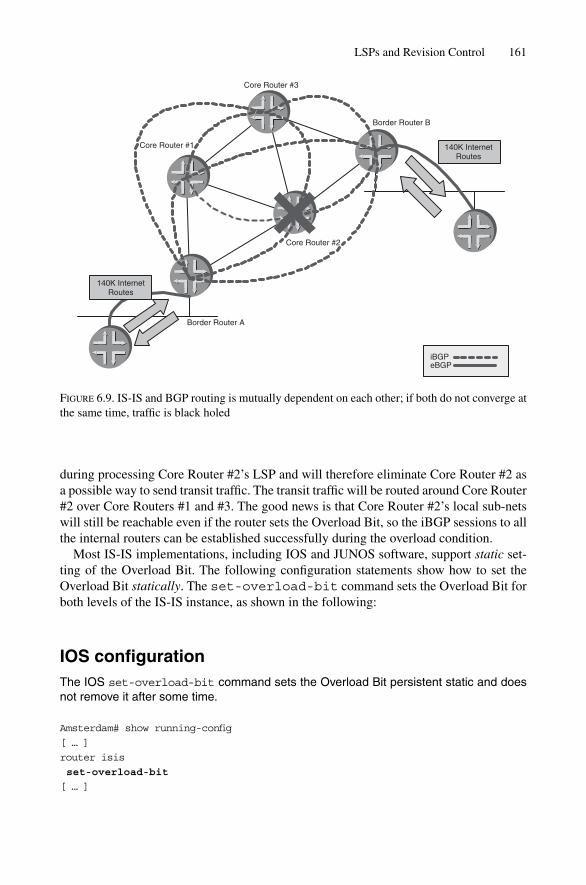
during processing Core Router #2’s LSP and will therefore eliminate Core Router #2 asa possible way to send transit traffic. The transit traffic will be routed around Core Router#2 over Core Routers #1 and #3. The good news is that Core Router #2’s local sub-netswill still be reachable even if the router sets the Overload Bit, so the iBGP sessions to allthe internal routers can be established successfully during the overload condition.
Most IS-IS implementations, including IOS and JUNOS software, support static set-ting of the Overload Bit. The following configuration statements show how to set theOverload Bit statically. The set-overload-bit command sets the Overload Bit forboth levels of the IS-IS instance, as shown in the following:
IOS configurationThe IOS set-overload-bit command sets the Overload Bit persistent static and doesnot remove it after some time.
Amsterdam# show running-config
[ … ]
router isis
set-overload-bit
[ … ]
LSPs and Revision Control 161
FIGURE 6.9. IS-IS and BGP routing is mutually dependent on each other; if both do not converge atthe same time, traffic is black holed
140K InternetRoutes
Core Router #1
Core Router #3
Border Router B
Border Router A
Core Router #2
iBGPeBGP
140K InternetRoutes
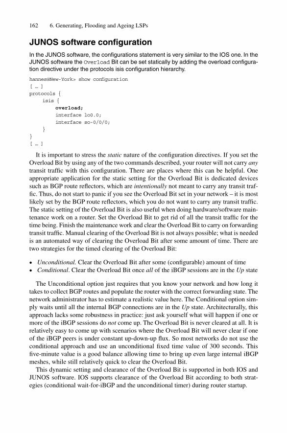
JUNOS software configurationIn the JUNOS software, the configurations statement is very similar to the IOS one. In theJUNOS software the Overload Bit can be set statically by adding the overload configura-tion directive under the protocols isis configuration hierarchy.
hannes@New-York> show configuration
[ … ]
protocols {
isis {
overload;
interface lo0.0;
interface so-0/0/0;
}
}
[ … ]
It is important to stress the static nature of the configuration directives. If you set theOverload Bit by using any of the two commands described, your router will not carry anytransit traffic with this configuration. There are places where this can be helpful. Oneappropriate application for the static setting for the Overload Bit is dedicated devicessuch as BGP route reflectors, which are intentionally not meant to carry any transit traf-fic. Thus, do not start to panic if you see the Overload Bit set in your network – it is mostlikely set by the BGP route reflectors, which you do not want to carry any transit traffic.The static setting of the Overload Bit is also useful when doing hardware/software main-tenance work on a router. Set the Overload Bit to get rid of all the transit traffic for thetime being. Finish the maintenance work and clear the Overload Bit to carry on forwardingtransit traffic. Manual clearing of the Overload Bit is not always possible; what is neededis an automated way of clearing the Overload Bit after some amount of time. There aretwo strategies for the timed clearing of the Overload Bit:
• Unconditional. Clear the Overload Bit after some (configurable) amount of time• Conditional. Clear the Overload Bit once all of the iBGP sessions are in the Up state
The Unconditional option just requires that you know your network and how long ittakes to collect BGP routes and populate the router with the correct forwarding state. Thenetwork administrator has to estimate a realistic value here. The Conditional option sim-ply waits until all the internal BGP connections are in the Up state. Architecturally, thisapproach lacks some robustness in practice: just ask yourself what will happen if one ormore of the iBGP sessions do not come up. The Overload Bit is never cleared at all. It isrelatively easy to come up with scenarios where the Overload Bit will never clear if oneof the iBGP peers is under constant up-down-up flux. So most networks do not use theconditional approach and use an unconditional fixed time value of 300 seconds. Thisfive-minute value is a good balance allowing time to bring up even large internal iBGPmeshes, while still relatively quick to clear the Overload Bit.
This dynamic setting and clearance of the Overload Bit is supported in both IOS andJUNOS software. IOS supports clearance of the Overload Bit according to both strat-egies (conditional wait-for-iBGP and the unconditional timer) during router startup.
162 6. Generating, Flooding and Ageing LSPs
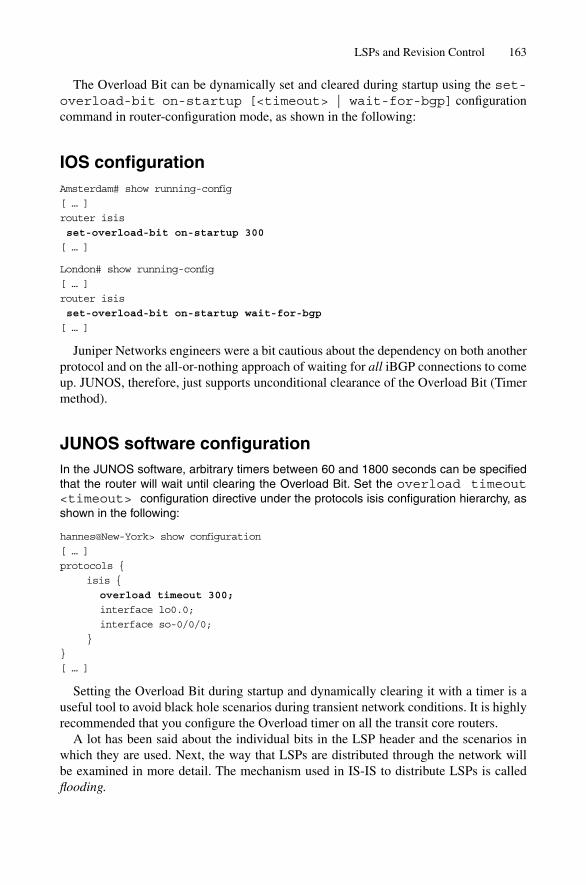
The Overload Bit can be dynamically set and cleared during startup using the set-overload-bit on-startup [<timeout> | wait-for-bgp] configurationcommand in router-configuration mode, as shown in the following:
IOS configurationAmsterdam# show running-config
[ … ]
router isis
set-overload-bit on-startup 300
[ … ]
London# show running-config
[ … ]
router isis
set-overload-bit on-startup wait-for-bgp
[ … ]
Juniper Networks engineers were a bit cautious about the dependency on both anotherprotocol and on the all-or-nothing approach of waiting for all iBGP connections to comeup. JUNOS, therefore, just supports unconditional clearance of the Overload Bit (Timermethod).
JUNOS software configurationIn the JUNOS software, arbitrary timers between 60 and 1800 seconds can be specifiedthat the router will wait until clearing the Overload Bit. Set the overload timeout<timeout> configuration directive under the protocols isis configuration hierarchy, asshown in the following:
hannes@New-York> show configuration
[ … ]
protocols {
isis {
overload timeout 300;
interface lo0.0;
interface so-0/0/0;
}
}
[ … ]
Setting the Overload Bit during startup and dynamically clearing it with a timer is auseful tool to avoid black hole scenarios during transient network conditions. It is highlyrecommended that you configure the Overload timer on all the transit core routers.
A lot has been said about the individual bits in the LSP header and the scenarios inwhich they are used. Next, the way that LSPs are distributed through the network will be examined in more detail. The mechanism used in IS-IS to distribute LSPs is calledflooding.
LSPs and Revision Control 163
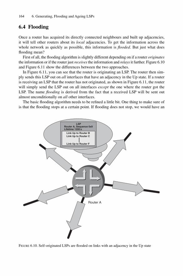
6.4 Flooding
Once a router has acquired its directly connected neighbours and built up adjacencies,it will tell other routers about its local adjacencies. To get the information across thewhole network as quickly as possible, this information is flooded. But just what doesflooding mean?
First of all, the flooding algorithm is slightly different depending on if a router originatesthe information or if the router just receives the information and relays it further. Figure 6.10and Figure 6.11 show the differences between the two approaches.
In Figure 6.11, you can see that the router is originating an LSP. The router then sim-ply sends this LSP out on all interfaces that have an adjacency in the Up state. If a routeris receiving an LSP that the router has not originated, as shown in Figure 6.11, the routerwill simply send the LSP out on all interfaces except the one where the router got theLSP. The name flooding is derived from the fact that a received LSP will be sent outalmost unconditionally on all other interfaces.
The basic flooding algorithm needs to be refined a little bit. One thing to make sure ofis that the flooding stops at a certain point. If flooding does not stop, we would have an
164 6. Generating, Flooding and Ageing LSPs
LSP
Link Up to Router BLink Up to Router C
Link Up to Router F
Router A, Sequence 0x9Lifetime 1200 s
Router A
FIGURE 6.10. Self-originated LSPs are flooded on links with an adjacency in the Up state
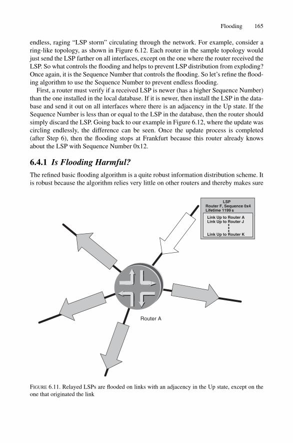
endless, raging “LSP storm” circulating through the network. For example, consider aring-like topology, as shown in Figure 6.12. Each router in the sample topology wouldjust send the LSP farther on all interfaces, except on the one where the router received theLSP. So what controls the flooding and helps to prevent LSP distribution from exploding?Once again, it is the Sequence Number that controls the flooding. So let’s refine the flood-ing algorithm to use the Sequence Number to prevent endless flooding.
First, a router must verify if a received LSP is newer (has a higher Sequence Number)than the one installed in the local database. If it is newer, then install the LSP in the data-base and send it out on all interfaces where there is an adjacency in the Up state. If theSequence Number is less than or equal to the LSP in the database, then the router shouldsimply discard the LSP. Going back to our example in Figure 6.12, where the update wascircling endlessly, the difference can be seen. Once the update process is completed(after Step 6), then the flooding stops at Frankfurt because this router already knowsabout the LSP with Sequence Number 0x12.
6.4.1 Is Flooding Harmful?The refined basic flooding algorithm is a quite robust information distribution scheme. Itis robust because the algorithm relies very little on other routers and thereby makes sure
Flooding 165
LSP
Link Up to Router ALink Up to Router J
Link Up to Router K
Router F, Sequence 0x4Lifetime 1199 s
Router A
FIGURE 6.11. Relayed LSPs are flooded on links with an adjacency in the Up state, except on theone that originated the link
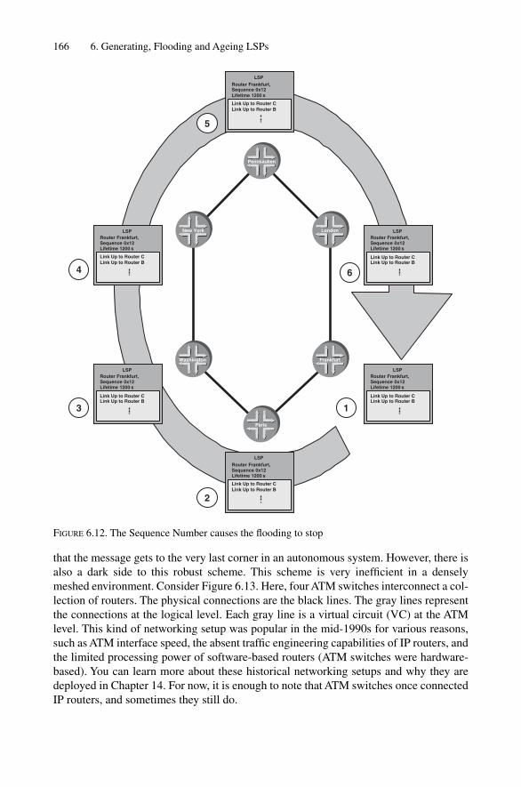
that the message gets to the very last corner in an autonomous system. However, there isalso a dark side to this robust scheme. This scheme is very inefficient in a denselymeshed environment. Consider Figure 6.13. Here, four ATM switches interconnect a col-lection of routers. The physical connections are the black lines. The gray lines representthe connections at the logical level. Each gray line is a virtual circuit (VC) at the ATMlevel. This kind of networking setup was popular in the mid-1990s for various reasons,such as ATM interface speed, the absent traffic engineering capabilities of IP routers, andthe limited processing power of software-based routers (ATM switches were hardware-based). You can learn more about these historical networking setups and why they aredeployed in Chapter 14. For now, it is enough to note that ATM switches once connectedIP routers, and sometimes they still do.
166 6. Generating, Flooding and Ageing LSPs
LSP
Link Up to Router CLink Up to Router B
Router Frankfurt,Sequence 0x12Lifetime 1200s
LSP
Link Up to Router CLink Up to Router B
Router Frankfurt,Sequence 0x12Lifetime 1200 s
LSP
Link Up to Router CLink Up to Router B
Router Frankfurt,Sequence 0x12Lifetime 1200s
LSP
Link Up to Router CLink Up to Router B
Router Frankfurt,Sequence 0x12Lifetime 1200 s
LSP
Link Up to Router CLink Up to Router B
Router Frankfurt,Sequence 0x12Lifetime 1200s
LSP
Link Up to Router CLink Up to Router B
Router Frankfurt,Sequence 0x12Lifetime 1200 s
LSP
Link Up to Router CLink Up to Router B
Router Frankfurt,Sequence 0x12Lifetime 1200s
LSP
Link Up to Router CLink Up to Router B
Router Frankfurt,Sequence 0x12Lifetime 1200 s
LSP
Link Up to Router CLink Up to Router B
Router Frankfurt,Sequence 0x12Lifetime 1200s
LSP
Link Up to Router CLink Up to Router B
Router Frankfurt,Sequence 0x12Lifetime 1200 s
LSP
Link Up to Router CLink Up to Router B
Router Frankfurt,Sequence 0x12Lifetime 1200s
LSP
Link Up to Router CLink Up to Router B
Router Frankfurt,Sequence 0x12Lifetime 1200 s
6
5
4
3
2
1
Pennsauken
Frankfurt
London
Washington
New York
Paris
FIGURE 6.12. The Sequence Number causes the flooding to stop

Each router in the Figure 6.13 setup forms an adjacency with the other routers, effectivelyforming a full-mesh. So far, so good. Now, consider the following scenario: the ATM vir-tual circuit between Seattle and Los Angeles breaks for some reason, as indicated by thedotted gray line. Both Seattle and LA notice the break and therefore generate a new LSP(incrementing the Sequence Number and removing the adjacency between Seattle andLA). The new LSP is sent according to the flooding rule on all interfaces where there areadjacencies in the Up state. Thus, both Seattle and LA send four copies (gray arrows) oftheir new LSPs into the network. Next, the four other routers will receive the two LSPs(white arrows). Here is where the trouble starts: because the flooding algorithm is so sim-ple, the algorithm does not yet know that all the other routers already been have updatedand know that the adjacency between Seattle and LA is down. What follows is a multi-plication of LSPs due to the simplicity of the flooding algorithm. All of the routersreceive the two new LSPs and re-send the LSP to all the logical interfaces except on theones on which they got the LSP (gray arrows). What results is that 32 LSPs are sent fora single broken ATM VC. This does not sound too stressful for a modern router’s controlplane; however, just think if there are not six routers, but 100 routers in the network. Theproblem is that the number of LSPs grows by the square of the number of routers, or inmathematical speak O(N 2). Thus, a single failing VC in the network may generate up to10,000 LSP updates, all flying around in a relatively short amount of time. This is anawful lot of stress for the control plane of a router, no matter how powerful.
Flooding 167
tx LSP
rx LSP
Seattle
Los Angeles
San Francisco New York
Atlanta
Chicago
FIGURE 6.13. ATM overlay networks and flooding stress

Things get even worse with another failure scenario: what if not a single VC, but anentire router is going down (due to a reboot, for example)? The amount of LSPs growsby O(N3). In a network of 100 routers spanning a full-mesh, this means that a single fail-ing router generates up to 1,000,000 LSPs in a short amount of time. Ironically, 99 percent of the LSPs hold information that is already known by some other neighbour. Sowhat can be done to mitigate the dark side of flooding? The answer to this is discussed inthe next section.
6.4.2 Mesh-GroupsLet’s go back to the basic flooding algorithm and change it a little bit. Now the ruleis: Do not send out a received LSP on all the links where we have an adjacency in the Upstate. Rather, send out the LSP on some of these links. Figure 6.14 shows a router that is not sending out an LSP on all of the possible links. Instead, some links have been prunedoff the flooding topology. The result is that all routers still see LSP updates, but the exces-sive multiplication of LSPs is avoided. The official name for this kind of functionality isknown as Mesh-Groups and has been documented in RFC 2973. The Mesh-Group pruningis done based on the topology of the network and is not automatic.
There are two basic concepts behind Mesh-Groups. The first concept is blocking aninterface entirely, as shown in Figure 6.14. Here, one or a set of interfaces is removedfrom the flooding list. It is also very straightforward to configure on IOS and JUNOSsoftware, as shown in the following two configuration snippets. Both vendors share thesame spirit in their implementation of the Mesh-Group functionality. The LSP floodingin both vendors’ implementations is an interface property. In IOS, you configure everythingat the physical/logical interfaces prepended by the keyword isis. In JUNOS software,all the logical interfaces can be referenced directly under the protocols isisinterface configuration branch, which is very practical, as the relevant informationis then at one place.
168 6. Generating, Flooding and Ageing LSPs
tx LSP
rx LSP
Pruned "flooding" links
FIGURE 6.14. Mesh-Group blocks remove certain links from the flooding topology

IOS configurationIn IOS, LSP flooding can be reduced using the isis mesh-group blocked configurationcommand in interface-configuration mode, as shown in the following:
London# show running-config
[ … ]
interface atm 1/2.1
ip router isis
isis mesh-group blocked
[ … ]
In JUNOS the configurations statement is very similar. The first flavour of Mesh-Groups can be enabled by use of the mesh-group blocked config-uration directiveunder the protocols isis interface <interface-name> configurationhierarchy, as shown in the following:
JUNOS software configurationhannes@Frankfurt> show configuration
[ … ]
protocols {
isis {
interface at-4/0/0.200 {
mesh-group blocked;
}
}
}
[ … ]
You may ask why the word Group is contained in Mesh-Group. So far we have not con-figured a Group number. What is the Group number related to? This number is related to therefined version of Mesh-Groups where the flooding is not turned off entirely for an interface.Some LSPs are still sent. How is this second flavour of Mesh-Groups configured? First, allthe logical interfaces on an IS-IS router have to be organized in groups of interfaces. InFigure 6.15 you can see that the first three interfaces have been grouped together in Mesh-Group #11 and the second three interfaces have been grouped together in Mesh-Group #47.Once an LSP is received over a logical interface (white arrow), the IS-IS router first deter-mines the Mesh-Group number that the receiving interface belongs to. In our example thereceiving interface belongs to Mesh-Group #11. When this LSP is now flooded to all neigh-bours, the router does flood the LSP on interfaces belonging to that specific group (Mesh-Group #11 with the gray arrows). This solves the multiplicative effect of basic flooding.
The second flavour of Mesh-Groups that has just been described can be configured ina similar way on IOS and in the JUNOS software. The only difference here is that aMesh-Group Number replaces the keyword blocked. Similar to the mesh-groupblocked command, this is configured under interface configuration mode.
Flooding 169
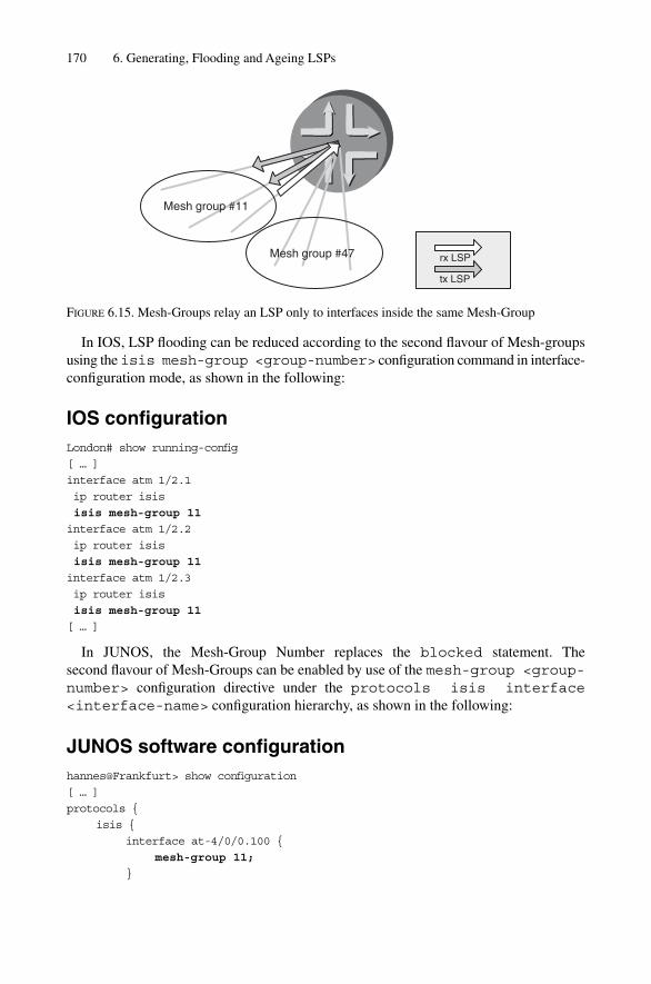
In IOS, LSP flooding can be reduced according to the second flavour of Mesh-groupsusing the isis mesh-group <group-number> configuration command in interface-configuration mode, as shown in the following:
IOS configurationLondon# show running-config
[ … ]
interface atm 1/2.1
ip router isis
isis mesh-group 11
interface atm 1/2.2
ip router isis
isis mesh-group 11
interface atm 1/2.3
ip router isis
isis mesh-group 11
[ … ]
In JUNOS, the Mesh-Group Number replaces the blocked statement. The second flavour of Mesh-Groups can be enabled by use of the mesh-group <group-number> configuration directive under the protocols isis interface<interface-name> configuration hierarchy, as shown in the following:
JUNOS software configurationhannes@Frankfurt> show configuration
[ … ]
protocols {
isis {
interface at-4/0/0.100 {
mesh-group 11;
}
170 6. Generating, Flooding and Ageing LSPs
Mesh group #11
Mesh group #47
tx LSP
rx LSP
FIGURE 6.15. Mesh-Groups relay an LSP only to interfaces inside the same Mesh-Group

Flooding 171
interface at-4/0/0.101 {
mesh-group 11;
}
interface at-4/0/0.102 {
mesh-group 11;
}
}
}
[ … ]
Mesh-Groups help to reduce the flooding explosion in densely meshed environments.However, keep in mind that flooding is a necessity to get information across the internalnetwork. In a sense, it is “too-much” flooding that causes harm. However, a “too-little”flooding strategy can cause harm in a different way. Thus, be very careful when settingup Mesh-Groups. Mesh-Groups cannot be so “tight” that they result in desynchronizedlink-state databases. In Chapter 8 you will learn about the impact of desynchronizedlink-state databases and what can be done to avoid them. At the end of the chapter, arefinement of ISO 10589 is presented to make sure that routers that have been acciden-tally pruned off the flooding topology (due to a wrong Mesh-Group configuration, forexample) still receive good information for synchronization.
Although Mesh-Groups must be hand-configured by a network administrator, it iseasy to determine if Mesh-Groups are needed by looking at the statistics that IOS and theJUNOS software can provide. For example, the relevant IS-IS statistics can be displayedusing the show clns traffic command, as shown in the following:
IOS command outputAmsterdam# show clns traffic
[ … ]
IS-IS: Time since last clear: never
IS-IS: Level-1 Hellos (sent/rcvd): 115/19
IS-IS: Level-2 Hellos (sent/rcvd): 120/14
IS-IS: PTP Hellos (sent/rcvd): 0/0
IS-IS: Level-1 LSPs sourced (new/refresh): 10/0
IS-IS: Level-2 LSPs sourced (new/refresh): 14/0
IS-IS: Level-1 LSPs flooded (sent/rcvd): 2/2
IS-IS: Level-2 LSPs flooded (sent/rcvd): 3/2
IS-IS: LSP Retransmissions: 0
IS-IS: Level-1 CSNPs (sent/rcvd): 0/2
IS-IS: Level-2 CSNPs (sent/rcvd): 3/0
IS-IS: Level-1 PSNPs (sent/rcvd): 0/0
IS-IS: Level-2 PSNPs (sent/rcvd): 0/0
IS-IS: Level-1 DR Elections: 3
IS-IS: Level-2 DR Elections: 2
IS-IS: Level-1 SPF Calculations: 7
IS-IS: Level-2 SPF Calculations: 7
172 6. Generating, Flooding and Ageing LSPs
IS-IS: Level-1 Partial Route Calculations: 0
IS-IS: Level-2 Partial Route Calculations: 0
IS-IS: LSP checksum errors received: 0
IS-IS: Update process queue depth: 0/200
IS-IS: Update process packets dropped: 0
[ … ]
In every case, a big disparity between the LSPs being sent and the LSPs being receivedis an indication that there is excess flooding in the network that needs to be controlled viaMesh-Groups.
In the JUNOS software, you can display the global lS-IS statistics using the show isisstatistics command. Watch for a disparity between LSPs being sent and received:
JUNOS software command outputhannes@Frankfurt> show isis statistics
IS-IS statistics for Frankfurt:
PDU type Received Processed Drops Sent Rexmit
LSP 220201 220201 0 152846 381
IIH 5640823 5640823 0 3762071 0
CSNP 5486953 5486953 0 9893412 0
PSNP 32766 32766 0 192857 0
Unknown 0 0 0 0 0
Totals 11380743 11380743 0 14001186 381
Total packets received: 11380743 Sent: 14001567
SNP queue length: 0 Drops: 0
LSP queue length: 0 Drops: 0
SPF runs: 121371
Fragments rebuilt: 336
LSP regenerations: 151
Purges initiated: 0
Mesh-Groups solved a big problem in ATM or Frame-Relay overlay networks of themid-1990s. However, today Mesh-Groups are of limited use because ATM and FR trans-port networks connecting routers have gone away for the most part. Today, routers aretypically interconnected by packet-over-SONET/SDH links in a sparse-meshed fashion.A typical core router these days has on average no more than four or five interfaces facingother core routers. In these environments, Mesh-Groups are a nice tuning capability, butnot the necessity they were only a few years ago when networks were melting down inthe absence of a sound LSP flooding scheme.
6.5 Network-wide Purging of LSPs
The flooding of LSP updates the network with the most accurate state information. Thelink-state database is therefore continually increasing as new or updated information is

added to it. If a link is down, issue a new LSP. When it comes back up, issue another newLSP. So far there have been no negative LSPs that make the database shrink in size. Butwhat if IS-IS wants to remove a router from the distributed link-state database in all ofthe other routers in the network? There is always the option to wait until the LSP agesout, but that can take up to 65,535 seconds (18 hours, 12 minutes). For certain events,such as router removal, IS-IS needs to have the capability to issue a negative LSP update.This negative LSP, or purge LSP, exists and is a “crippled” version of the original LSP.All the purge LSP contains is the LSP header without any further information. TheHeader and the Checksum fields of the purge LSP header are set to zero to indicate thatthis is a purge. This negative LSP update, which is called a network-wide purge, is usedfor a variety of events. One of these events is DIS election.
6.5.1 DIS ElectionOn IS-IS broadcast links there is at least one router performing a special function. ThisIS-IS router is called the Designated Intermediate System (DIS). The role of the DIS was first discussed in Chapter 5. Each DIS borrows an ID that is unique across the net-work from the LAN on which it is the DIS. The DIS floods that LAN-ID throughout the network to tell other routers that there is connectivity to the LAN. Now, if the DIS ischanged (re-elected) due to changes, such as a higher DIS election priority or the time-out of the old DIS, then the new DIS must generate a new LAN-ID and flood thisthroughout the network. The has-been DIS needs to remove the old LAN-ID from the network in order to ensure that it does not lead to corrupt network information.Figure 6.16 shows the chain of LSPs that are generated to accomplish this. In order to remove the stale LSP from the former DIS, the old DIS generates an LSP with thesequence number incremented by one, but with the Checksum and Lifetime set to zero. Each router that receives this purge LSP will remove the referenced LSP-ID fromits link-state database.
Network-wide Purging of LSPs 173
Local LAN
Oldpseudonode
Old DIS
Newpseudonode
Old DIS
FIGURE 6.16. At DIS re-election the old pseudo node LSP gets purged

6.5.2 Expiration of LSPsWhenever a router ages-out an LSP whose Lifetime has become zero, it needs to tell theother routers that the LSP has been aged out. Recall that each router has an internal clockand those clocks are subject to clock drifts. At the same time, all the routers in a given IS-IS level fundamentally rely on the fact that its link-state database is synchronized with allothers. So for further robustness in the face of clock drift, the first router that detects thatan LSP’s Lifetime has gone to zero, initiates a network-wide purge of that expired LSP.Lifetime expiration of LSPs is common for routers that have been removed from the net-work for one reason or another. Recall that under normal conditions, each LSP getsrefreshed by the Originator before it expires and therefore should never countdown theLifetime field to zero. This should only happen during the purge of an LSP.
If a router purges an LSP from the link-state database, the LSP is not removed imme-diately. Instead, the LSP is retained for a ZeroAgeLifetime of 60 seconds. Keeping thepurged LSP for 60 seconds ensures that an LSP is not re-learned (for instance) throughan adjacency that has been Down and is now transitioning to Up again.
You can recognize a purged LSP that is still in the database if its Lifetime value is inbrackets. This is similar to the accounting world, where red numbers are in brackets aswell. And this is exactly what the User Interfaces do as well: they essentially show you azombie – an LSP that is already dead but we keep it alive for visibility, helping us in thetroubleshooting case.
IOS command outputAmsterdam# show isis database
[ … ]
IS-IS Level-1 Link State Database:
LSPID LSP Seq Num LSP Checksum LSP Holdtime ATT/P/OL
New-York.02-00 0x00002fb1 0x6f71 (23) 1/0/0
[ … ]
JUNOS software command outputhannes@New-York> show isis database
IS-IS level 1 link-state database:
LSP ID Sequence Checksum Lifetime Attributes
New-York.02-00 0x2fb1 0x6f71 (48) L1 Attached
[ … ]
4 LSPs
Typically you do not see much purged LSPs in your database as this is a very rare case(DIS routers do not change very often). However, if you see a lot of bracketed LPSs orone LSP always containing a bracketed Lifetime then probably a malicious event like aflood-purge storm is raging because of duplicate System-IDs.
174 6. Generating, Flooding and Ageing LSPs

6.5.3 Duplicate System-IDsWhenever a router receives an LSP that contains its own System-ID as Originator, andthe router is sure that it did not generate this LSP, the router must assume that there isanother router on the network that is configured with a duplicate System-ID. All thereceiving router can do is to log this event and generate a purge LSP. The other router willmost likely try to re-originate this LSP with a higher Sequence Number. Of course, thispurge process needs to be carefully paced. Otherwise a flood-purge-storm will start torage as the two routers continually try to update and purge each other’s wrong LSP. Youwill see in the next section how these storms can be prevented. Actually, the LSP will bepurged because duplicate System-IDs are also an obstacle for a clean SPF calculation.This ensures that the network itself stays clean.
6.6 Flow Control and Throttling of LSPs
In link-state routing protocols, the implementer needs to make an effort not to over-whelm neighbours with excessive LSP updates. Excessive LSPs might churn the net-work. In typical transport protocols such as TCP there is a built-in feedback mechanismthat makes the sender slow down if the receiver feels overwhelmed. This is called flowcontrol. However, virtually all IGPs (including IS-IS) have no way to tell a neighbourthat the IS-IS router is busy and make the other neighbouring routers throttle down LSPtransmissions. It is beyond the scope of this book as to why the protocol designers did notaddress flow control in the IS-IS specification. But this lack of flow control means thatan IS-IS router has to carefully pace (spread out in time) LSPs toward a neighbour. Ingood IS-IS implementations there are a lot of built-in throttles that make the IS-IS routerwell behaved, even when the network is in a transient stage and several LSP updates areflying around. Additionally, there are also limits for how frequently a router can originateLSP updates. A router not only has to take care that it does not overwhelm its directlyconnected neighbours, but the router needs to take care that it does not overwhelm all therouters that are beyond the immediately adjacent neighbouring routers. Recall that allrouters in a given IS-IS level need to dedicate some resources (such as CPU cycles,bandwidth and so on) to process and relay LSPs farther across the network. So let’s benice to these routers and not overload them, as we need them to distribute reachabilityinformation of all types.
Most modern implementations of the IS-IS protocol support a variety of control knobsthat makes an IS-IS router slower instead of faster. Realize that going slower when thereare transient conditions or LSP storms is the only option that a router has left if the routeris to continue running. There are a couple of big “Must-Not’s” that an implementation ofIS-IS should never do.
We must not trash our neighbours. IS-IS Hellos must always be sent. If a router doesnot send IS-IS Hellos in time, the adjacency times out. Losing an adjacency in transientsituations will additionally contribute more LSPs to a network that is already shaky tobegin with.
Flow Control and Throttling of LSPs 175

We must not forget to acknowledge LSPs of a neighbour. Even when a router is underpressure in the form of extreme packet loads, not acknowledging an LSP update meansthat after five seconds the LSP will be retransmitted. So it is much better to acknowledgethe LSP the first time before the LSP gets retransmitted. A retransmission consumes theresources of the neighbouring router as well as the receiving router because an LSP hasto be retransmitted by the neighbour and re-processed on the receiving side as well.
So if making things slower is the only thing a router can do, exactly what kind ofevents need to be made slower or throttled? The important events to throttle are in theareas of:
• The LSPs on an interface• Frequency of originating (generating) LSPs per router• Retransmissions on a interface
Each of these is discussed in the following sections.
6.6.1 LSP-transmit-intervalThe LSP transmit interval is one form of pacing that was originally mentioned in ISO10589. The specification says that an implementation of IS-IS should make sure not to sendmore than 30 LSPs per second on a given broadcast link. Both IOS and JUNOS softwareextended this requirement that LSPs are paced on every IS-IS interface type (broadcast andpoint-to-point). You can tweak that throttling timer in both JUNOS software and IOS.
In IOS, LSP throttling can be enabled using the isis lsp-interval <time>configuration command in interface-configuration mode. The time is a constantexpressed in milliseconds (ms). The default value is 33 ms. This example sets the LSP pacing so as not to exceed 20 LSPs per second (pacing of 50 ms means 20 LSPs per second).
IOS configurationLondon# show running-config
[ … ]
interface atm 1/2.1
ip router isis
isis lsp-interval 50
[ … ]
In JUNOS software, the throttling of LSPs can be enabled by use of the isis lsp-interval <time> configuration directive under the protocols isis interface<interface-name> configuration hierarchy. The default value is 20 ms and gener-ates 50 LSPs per second, which means that JUNOS software is contrary to the original20 LSP-per-second specification, but this limit is fairly old in that respect. Modern routersshould easily handle 50 LSPs per second. This example sets the JUNOS software value tothe specification limit of 50 ms (20 LSPs per second).
176 6. Generating, Flooding and Ageing LSPs

JUNOS software configurationhannes@Frankfurt> show configuration
[ … ]
protocols {
isis {
interface at-4/0/0.100 {
lsp-interval 50;
}
}
}
[ … ]
LSP throttling by use of the lsp-interval command is a powerful mechanism tocontrol the flooding pace to neighbouring routers in order to not overload them. There isanother issue that has not yet been discussed: control traffic (LSP and related packets)may “push back” the user traffic (information packets) because control traffic always hasprecedence in terms of scheduling on the router interface cards. Unfortunately, the con-trol traffic transmission rate does not get lower on low-bandwidth interfaces such as DS0or fractional T1/E1 line – control traffic stays the same. You can easily imagine that on alow-bandwidth circuit transmitting 30 full-MTU sized packets does not leave muchroom for other types of packets. So it would be nice if there were a way to tell the routerjust to utilize a certain percentage of the interface bandwidth for control traffic. In IOS,you can configure the bandwidth <bw> statement on a (sub)-interface so that therouter makes sure that there is not more than 50 per cent (for instance) of the interfacebandwidth utilized for LSP transmission. This is the recommended option to use for low-bandwidth circuits.
IOS configurationIn IOS, LSP throttling is calculated automatically by setting the bandwidth parameterin interface configuration mode – this makes sure that not more than 50 per cent (forexample) of the configured interface Bandwidth is dedicated to the routing protocol. Thisexample sets the total bandwidth available for IS-IS traffic to 256 Kbps, which might beonly a fraction of the total bandwidth available on the link (perhaps 2 Mbps):
London# show running-config
[ … ]
interface Serial1/2
ip router isisu
bandwidth 256
[ … ]
JUNOS software does not support automated calculation of LSP throttling because thelowest-speed interface cards on a Juniper Networks router starts at T1/E1 speeds (1.5 and2 Mbps) and it is assumed that even with an LSP pacing of 20 ms this will not consumemore than 50 per cent of the interface bandwidth. However, there may be fractional
Flow Control and Throttling of LSPs 177

T1/E1 circuits (less than the full bandwidth) configured as well, where LSP pacing mighthave to be adjusted.
However, the JUNOS software lsp-interval knob really helps to solve two prob-lems: regulating the control-traffic-to-user-traffic ratio, and protecting neighbours duringtransient situations. So the lack of direct bandwidth control is not really an issue: thesame knob can be used to solve both problems.
Note that the traffic subject to this pacing was non-self-originated traffic, which is traf-fic that has been originated by other routers, not the local router. In the next section, youlearn about pacing of self-originated LSPs that come from the local router.
6.6.2 LSP-generation-intervalRouters need to limit how fast they announce changes to the network. A router does not justsend an LSP and move on. Sending an LSP to the network essentially requests a replicationservice from the network to flood the LSP. So any LSP sent consumes tremendous resourcesfrom the network. The LSP sent may be replicated by hundreds of routers over thousandsof links. By inserting pacing rules on the individual routers, you can make sure that the net-work does not melt down once more than one router has to say something. The ISO 10589specification describes an architectural constant called minimumLSPGenerationIntervalthat serves this purpose. In vendor’s documentation this is sometimes referred to as LSPholddown. The IS-IS specification recommends setting this value to 30 seconds. Higherintervals may lead to routers that are not responsive to changes in the network, whereaslower values may generate too much churn in the network.
For a long time, IOS has implemented a 5 second holddown interval to keep a good balance between the two extremes. Today, the frequency of LSP origination can be controlled using the lsp-gen-interval <holddown> [<initial-wait><minimum-holddown>] configuration command. The first argument specifies thetime between LSP builds. This is the timer that ISO 10589 mentions and is discussed pre-viously. The interesting thing about LSP build holddown is that this is not enforced statically today. Modern implementations have a dynamic approach and try to strike a balance between responsiveness and stability. So there are two LSP holddown timers:a fast holddown and a slow holddown timer. Depending on how busy the network is, arouter switches from fast behaviour to slow behaviour. The first couple of LSP builds arescheduled very quickly without LSP build holddown consideration. However, if moreLSP builds are requested, then the router is probably in trouble and the router backs offto the normal slow LSP origination behaviour. The initial-wait timer specifieshow fast the router fires off an LSP after first building it. In transient situations a routerprobably needs to update its LSP a few times and this initial-wait timer helps byaccumulating a few builds. Minimum-wait controls the LSP build holddown in thefast phase.
How many LSPs need to be built until IOS switches from fast to slow behaviour? IOSuses a technique called exponential back off to toggle gradually between the two modes.Consider the IOS configuration snippet shown here. In IOS, there are three timers to con-trol LSP holddown. The first timer specifies the LSP holddown in the slow phaseexpressed in units of seconds. The second timer specifies how many milliseconds to wait
178 6. Generating, Flooding and Ageing LSPs

before sending the LSP. The third timer specifies the LSP holddown in the fast phaseexpressed in milliseconds.
IOS configurationLondon# show running-config
[ … ]
router isis
lsp-gen-interval 5 200 1000
[ … ]
Figure 6.17 shows the timing behaviour of the exponential back off algorithm. Afterthe first LSP is built it is delayed for 200 ms (second value given) until it gets sent. Next,the holddown timer kicks in, therefore the second LSP originated will be delayed for atleast 1000 ms (a full second) as specified in the third argument of the lsp-gen-interval configuration command. All subsequent LSP builds will be delayed bytwice the previous holddown time: 2 seconds for the third LSP, 4 seconds for the fourth,and so on. The holddown time is limited to the first argument (5 seconds) of the lsp-gen-interval command as a precaution that the interval does not grow to an infinitevalue. So for every fast-build the LSP-Origination-Interval gets larger until it hits theceiling of 5 seconds. After a particular router has stopped issuing LSPs for 20 seconds,the LSP holddown will be reset. This means that from here on any further LSP origin-ations will receive fast holddowns again, but only for the first couple of LSPs.
The JUNOS software scheme has a two-step rate limit. First, there is a global LSPthrottling similar to the one specified in ISO 10589. All the LSPs are paced using a 20 mstimer. Additionally, there is additional logic that damps adjacency and makes sure thatthe adjacency is reliably up for some time before advertising the adjacency. The globalLSP gating is hard-coded; there is no user interface knob to change the value. The slowLSP holddown value is a base value 10 seconds with 25 per cent jitter (timing variation)applied. That means that subsequent LSP builds will be randomly delayed between 7.5and 10 seconds. Jittering a timer makes the Event always happening earlier but neverlater than the original base value. This variation is useful to avoid global synchronizationand the associated LSP storms and router churn. Recall that a new LSP makes all routersdo several things at the same time (flooding, SPF calculation, and more), which in turnsynchronizes the CPU peaks in a network. Smearing the CPU peaks across routers byadding some timer jitter helps to avoid churn across all routers.
In JUNOS software, there are also a number of fast builds, which are currently hard-coded to three fast builds of LSPs. The initial wait timer is hard-coded to 20 ms beforethe LSP is sent. The reason why there are no configuration knobs is the JUNOS softwarehas adjacency holddown logic to make sure that the root cause of dynamic LSP changes(adjacency changes), will be damped (suppressed). Exactly how does this adjacencyholddown logic work? After a successful three-way handshake, the router does notdeclare the adjacency Up immediately. The router will wait to see if it can sustain theLSP stress generated from the new adjacency. Each new adjacency can generate a lot ofLSPs. Just think of a partitioned network that starts to heal. The healing router brings up
Flow Control and Throttling of LSPs 179

180
FIG
UR
E6.
17. E
xpon
entia
l hol
ddow
n gr
adua
lly s
upre
sses
LSP
s,ge
nera
tion
2000
4000
6000
8000
1000
012
000
t (m
s)
0
Firs
tLS
Pbu
ild
Sec
ond
LSP
build
and
sen
d
Firs
t LS
Pse
nt 2
00m
saf
ter
build
1000
ms
hold
dow
n20
00m
sho
lddo
wn
Thi
rd L
SP
build
and
sen
d
4000
ms
hold
dow
n
Fou
rth
LSP
build
and
sen
d
3200
0
5000
ms
hold
dow
n (m
ax h
oldd
own)
Afte
r 20
s fa
llbac
k to
fas
t be
havi
our

the adjacency and is exposed to a massive amount of new LSPs sent to it from the newpeer. In Chapter 8 you will acquire more insight as to just how IS-IS exchanges LSPs andthe mechanisms that synchronize link-state databases.
Can the router sustain the stress generated from all the new LSPs hammering at it? Therouter does not know yet. Does it make sense to advertise a new LSP if the network is influx? Probably not – so the router delays its own LSPs until the network is quieter. Justto be safe, the JUNOS software waits at least 20 seconds after an adjacency is declaredUp before doing anything further with the to-be-generated LSP. Next, the router starts tomeasure the arrival rate of LSPs to see if things have become more stabilized. JUNOSsoftware still holds the adjacency down until the LSP reception rate has gone down to 5LSPs/per 5 seconds. After the maximum holddown period of 60 seconds, which beginsafter the IS-IS 3-way handshake, the adjacency will finally be advertised in the LSP.
That two-level approach (LSP gating plus adjacency holddowns) has proven to be a goodmechanism that works in a variety of networking environements. The Juniper Networksdevelopment engineers felt that it was not necessary to expose a knob to change this behav-iour to the user. (Knobs are good – but the knobs that I do not need are even better.)
6.6.3 Retransmission IntervalAccording to ISO 10589, each IS-IS router has to acknowledge LSPs within a five-second window or else the neighbouring router will re-transmit that new LSP. A routerthat is in trouble may not be able to respond within the five seconds. Therefore it makessense to increase that retransmission timer to higher values for lower-powered, CPU-based routers. In JUNOS software, the five-second retransmission interval is hard codedand cannot be changed. In Cisco IOS the retransmission interval is configurable and canbe controlled on a per-interface basis.
IOS configurationIn IOS, the retransmission timer is configurable. Setting the isis retransmit-interval<interval> command in interface configuration mode controls this timer, as shown in thefollowing:
London# show running-config
[ … ]
router isis
isis retransmit-interval 5
[ … ]
In Cisco IOS, you can also control how fast LSPs are sent once a router is in theretransmission window. This is another mechanism that helps a busy neighbour andmakes sure that a sender does not overwhelm the receiving router with LSPs once thesender starts retransmitting LSPs. Here the router takes a non-acknowledgement of anLSP previously sent as a sign of trouble and therefore throttles down the LSP transmis-sion rate. Recall that the default LSP transmission rate in Cisco IOS is 33 ms betweenLSPs. The default retransmission-throttling interval increases that value by a factor of 3,
Flow Control and Throttling of LSPs 181

up to 100 ms. That should be sufficient to back off a troubled router. It is not recom-mended to go beyond 333 ms because the LSP pacing gets so slow that the networkbecomes unresponsive in terms of reaction to changes.
In IOS, the retransmission-throttling timer is configurable. Setting the isisretransmit-throttle-interval <interval> command in interface con-figuration mode controls this timer.
IOS configurationLondon# show running-config
[ … ]
router isis
isis isis retransmit-throttle-interval 200
[ … ]
6.7 Conclusion
The way in which an IS-IS implementation handles LSP dynamics separates amateurenthusiast code from professional developer’s routing code. LSP dynamics is perhaps themost important feature to focus on when evaluating IS-IS vendors. Interestingly, there isalmost nothing in the ISO 10589 specification that tells you how to implement IS-IS in a scalable and robust manner. For many router startups, the lack of experience in how todo this right has been a barrier to entrance in the high-end router market and it probablystill is. Ironically, in the world of open specifications, there are still barely a dozen routingprotocol software engineers who have the necessary experience to get the IS-IS coderight the first time. Do not be misled. I am not asserting that no other engineers but thesefew can ever get IS-IS right. With enough time, and with customers willing to take thepain to obtain that operational experience with regard to what works and what does not,sooner or later every implementation of IS-IS can get to a level of what is called Carrier-Class-Code. There are a number of interesting routing software approaches used byother vendors, but these are not discussed in this book. Time and operational experiencewill tell what implementation of IS-IS will finally prevail in the Internet.
182 6. Generating, Flooding and Ageing LSPs

7
Pseudonodes and Designated Routers
183
Historically routers were used to network local sub-nets to each other. Routing protocolsare optimized to run in a wide area network (WAN) environment which are typically point-to-point links like Serial Lines, Frame Relay or ATM. Due to the popularity of Ethernetsince the mid-1980s routing protocols are required to operate and scale on broadcast cir-cuits like Ethernet.
Broadcast networks allow multiple devices to see each other. For link-state routingprotocols like IS-IS multipoint capability means additional forms of stress in the domainsof Hello processing, database storage size dynamics like link-state database churn.
In this chapter you will learn how LAN circuits are different from p2p circuits, andwhat scaling challenges there are on p2p circuits. You will learn about the pseudonodeconcept, its nodal representation in the IS-IS link-state database and implications in theSPF algorithm. Finally the purpose of a Designated Intermediate System (DIS) and itselection, pre-emption and timing details will be highlighted.
7.1 Scaling Adjacencies on Large LANs
Whenever there is a large number of routers on a LAN, lots of care must be taken. Thereare several aspects of the protocol to worry about: first, if there is a large number ofspeakers on the LAN there is a lot amount of Hellos to process. Just imagine a LAN with100 IS-IS speakers generating in total 300 Hellos per second. If those 300 Hellos areevenly spread at one Hello each 3 milliseconds, as illustrated in Figure 7.1, no problem –this won’t stress the internal scheduling of the Router OS too much.
However, the environment, especially once it comes down to routing protocols is notnice and far from being ideal. Therefore we may never assume ideal working conditions.
7.1.1 The Self-synchronization ProblemMurphy’s Law dictates “If things can go wrong they will go wrong”. The worst case scenario is that 99 Hellos hit the control plane of the receiving router at once as shown in Figure 7.2. Although the average CPU stress remains moderate if all the Hellos areevenly spread, there could be a short time shortage of resources (buffer memory andCPU) if a large number of Hellos arrives at once. The last line of defence in a peak loadsituation is to drop incoming Hellos. Arguably the buffers should be made big enough toabsorb any peak load condition. So how big is big enough? One needs to make a trade-off here as well. Due to stability reasons a router should not buffer an almost infinite queueof incoming protocol packets. Processing very large queues may keep the router busy with

updates that are a few packets later withdrawn. On the other side there should be someminimum buffer to absorb short time bursts.
The worst case was previously described as “one Router hit by all Hellos of 99 Routersat once” and on first sight this might seem as unrealistic, artificial scenario. The reality isthat without precautions in the routing code generates Hellos there will be a resultingeffect called self-synchronization. Self-synchronization means that a router is immediatelyanswering with a Hello to network events like adjacency changes and new neighbours.This behaviour tends to add up by all the speakers on the LAN and as a side-effect all theHellos are scheduled at the same point, which is artificially generating an unwanted formof peak-stress followed by seconds of silence, as illustrated in Figure 7.2.
184 7. Pseudonodes and Designated Routers
Hello Receivedfrom 1921.6800.1005
t (ms)3 96 12 150
Hello Receivedfrom 1921.6800.1002
Hello Receivedfrom 1921.6800.1001
Hello Receivedfrom 1921.6800.1003
Hello Receivedfrom 1921.6800.1004
15
Hello Receivedfrom 1921.6800.1006
FIGURE 7.1. Even spread Hello arrival times are an ideal, desired environment
t (ms)3 60
Hello Receivedfrom 1921.6800.1004
Hello Receivedfrom 1921.6800.1003
Hello Receivedfrom 1921.6800.1001
Hello Receivedfrom 1921.6800.1002
Hello Receivedfrom 1921.6800.1005
Hello Receivedfrom 1921.6800.1006
FIGURE 7.2. A lot of Hellos hitting the control plane CPU at the same time may exhaust resources

7.1.2 Scheduling HellosHow is the Hello scheduled? This depends on the Hold timer which controls adjacencyexpiration. In order to avoid adjacency expiration each neighbouring router sends Hellosto reset the Hold timer before it expires. In every implementation of IS-IS there is an internalconstant called the Hello-Multiplier. The Hello Interval is calculated by dividing theHold timer by the Hello-Multiplier. The Hold timer reset by receipt of an Hello is illus-trated in Figure 5.3 in Chapter 5 “Neighbour Discovery and Handshaking”.
For example, a Hold timer of 30 s and a Hello-Multiplier of 3 results in a Hello Intervalof 10 s. If the system dispatches exactly each 10 s a Hello then there may be risk that thesystem is starting to self-synchronize and after some local network events all routers onthe LAN will generate their Hellos at the same point in time.
To avoid the effect of self-synchronization ISO 10589 mandates to jitter timers forscheduling Hellos.
7.1.3 Applying Jitter to TimersWhat does applying a jitter to timers mean and how does it attempt to solve the self-synchronization problem?
Applying a jitter means scheduling a Hello before it must be sent. The trick is that eachrouter on a LAN deducts a random time off the original Hello timer. Because each routercomputes its own independent random number it is made sure that routers never sendHellos at the same point in time.
ISO 10589 mandates to apply a 25 per cent jitter on Hellos. The 25 per cent mean thata random number between the 0 and 25 per cent mark of the original timer is computed.The random number should be truly random in the sense that the numbers the random-generator produces have a uniform distribution over the entire space that it covers. Forexample, a 25 per cent jitter of an underlying 10 s Hello timer would result in a randomtime between 0 and 2.5 seconds. Finally the jitter is subtracted from the original timer. InFigure 7.3 the jitter calculation is illustrated.
Both IOS and JUNOS do apply a 25 per cent jitter to their Hello timer before schedulingthe Hello for transmission. In the following tcpdump output you can see that the Timestampsare not spaced in discrete 10 s intervals – it is always varying a little less than 10 s.
Tcpdump output00:11:39.391338 OSI, IS-IS, L1 Lan IIH, src-id 0000.0000.0002,
lan-id 0000.0000.0001.02, prio 65, length 74
00:11:48.951503 OSI, IS-IS, L1 Lan IIH, src-id 0000.0000.0002,
lan-id 0000.0000.0001.02, prio 65, length 74
00:11:57.061652 OSI, IS-IS, L1 Lan IIH, src-id 0000.0000.0002,
lan-id 0000.0000.0001.02, prio 65, length 74
00:12:05.451811 OSI, IS-IS, L1 Lan IIH, src-id 0000.0000.0002,
lan-id 0000.0000.0001.02, prio 65, length 74
00:12:14.671953 OSI, IS-IS, L1 Lan IIH, src-id 0000.0000.0002,
lan-id 0000.0000.0001.02, prio 65, length 74
Scaling Adjacencies on Large LANs 185

Applying a jitter on the timers offers a good distribution of the scheduled Hellos among theLAN routers over time. It is used in many other places as well. IOS and JUNOS go much fur-ther as required by ISO 10589. For almost every one-time and periodic event the systemapplies jitter. Virtually all IS-IS packet dispatching routines apply between 5 per cent and 25per cent jitter for Hellos (IIHs), Sequence Number PDUs (SNPs) and link-state PDUs (LSPs).
As soon as the router maintains a high number of adjacencies on the LAN circuit it needsto advertise them in its link-state PDU. A large number of LAN adjacencies raises the ques-tion of how to represent all the router-to-router relationships in the link-state database.
7.2 Pseudonodes
See Figure 7.4 for an illustration of six routers that are located on the same LAN. The LANis transitive; this means that all the routers can see each other. Each of the routers gener-ates an LSP and tells the world that it has five neighbours on the LAN by explicitly list-ing them inside the IS Reachability TLV #2 or #22.
Any-to-any connectivity lets grow the size of the link-state database by an order ofO(N 2). This is often referred to as the N2 problem.
7.2.1 The N2 ProblemFigure 7.5 illustrates the relationship between the size of IS-reach information in thelink-state database and the number of routers on a LAN. Arguably the absolute size of thelink-state database is a moderate problem compared to the dynamic effects of a full-meshadvertisement. Every time a new router N gets on the LAN, all the other routers (N � 1)that have been on the LAN previously need to update their LSPs to list the adjacency tothe new router. This results in a massive LSP update storm because all the routers on theLAN need to tell the network that there has been a change in adjacencies. The sameupdate storm happens if a router is disconnected from the LAN.
The dynamic component (routers joining or leaving the sub-net) is a more importantproblem than database storage size.
186 7. Pseudonodes and Designated Routers
10s
Hello Timer
t (s)2 100 4 6 8
Randomjitter
1 3 5 7 9
2.5s
FIGURE 7.3. A 25 per cent jitter on the basis of a 10 s timer results in a random Hello between 7.5 and 10 s
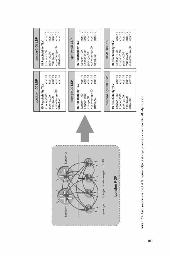
Lo
nd
on
PO
P
Lond
on-1
Lond
on-2
peer
-gw
vpn-
gwcu
stom
er-g
wB
RA
S
IS R
each
abili
ty T
LV
Lond
on-1
.00
LS
P
cost
10
cost
10
cost
10
cost
10
cost
10
Lond
on-2
.00
peer
-gw
.00
vpn-
gw.0
0cu
stom
er-g
w.0
0B
RA
S.0
0
IS R
each
abili
ty T
LV
peer
-gw
.00
LS
P
cost
10
cost
10
cost
10
cost
10
cost
10
Lond
on-1
.00
Lond
on-2
.00
vpn-
gw.0
0cu
stom
er-g
w.0
0B
RA
S.0
0
IS R
each
abili
ty T
LV
Lond
on-2
.00
LS
P cost
10
cost
10
cost
10
cost
10
cost
10
Lond
on-1
.00
peer
-gw
.00
vpn-
gw.0
0cu
stom
er-g
w.0
0B
RA
S.0
0
IS R
each
abili
ty T
LV
vpn-
gw.0
0L
SP co
st 1
0co
st 1
0co
st 1
0co
st 1
0co
st 1
0
Lond
on-1
.00
Lond
on-2
.00
peer
-gw
.00
cust
omer
-gw
.00
BR
AS
.00
IS R
each
abili
ty T
LV
cust
omer
-gw
.00
LS
P
cost
10
cost
10
cost
10
cost
10
cost
10
Lond
on-1
.00
Lond
on-2
.00
peer
-gw
.00
vpn-
gw.0
0B
RA
S.0
0
IS R
each
abili
ty T
LV
BR
AS
.00
LS
P cost
10
cost
10
cost
10
cost
10
cost
10
Lond
on-1
.00
Lond
on-2
.00
peer
-gw
.00
vpn-
gw.0
0cu
stom
er-g
w.0
0
FIG
UR
E7.
4.Fi
ve r
oute
rs o
n th
e L
AN
req
uire
O(N
2 ) s
tora
ge s
pace
to a
ccom
mod
ate
all a
djac
enci
es
187

The IS-IS protocol design team was challenged to turn this N2 problem into a linearproblem in order to scale more nicely. The solution to this problem is changing the rep-resentation of the LAN in the link-state database. The LAN is represented by so-calledpseudonodes. Pseudonodes are comparable to the Network LSA Type #2 in OSPF andare a very common concept in link-state routing protocols.
7.2.2 Pseudonode RepresentationThe solution the IS-IS design team came up with is quite straightforward: the router-to-router relationship is modelled in the link-state database just like the real physical con-nection relationship:
• Each router is connected to the LAN• The LAN is connected to all the routers
So the idea of giving the LAN a nodal representation in the link-state database wasborn. Figure 7.6 shows how the LAN is represented in the link-state database as a nodesimilar to a router.
The question is now who inserts the LAN node in the link-state database? How can wemake the LAN node speak and perform all the necessary tasks that a real IS-IS router hasto do, like generating, refreshing and if necessary removing LSPs?
One thing is clear: a LAN is a dumb piece of wire and has no logic to perform said tasks.Therefore some router on the LAN has to represent the LAN in the link-state database. Itis almost like lending the LAN its voice. On each LAN circuit a Designated IntermediateSystem (DIS) is elected. The DIS is a router among the IS-IS routers on the LAN, whichhas, additionally to its normal duties, the purpose of representing the LAN in the link-statedatabase. Because the node that the DIS generates in addition to its very own node is nota real routing node it is called a pseudonode.
Changing the representation from an any-to-any IS-reach mesh to a star topology withthe pseudonode in the middle, greatly reduces the amount of adjacencies that routers on
188 7. Pseudonodes and Designated Routers
IS-IS adjacencies on broadcast LANs
0100200300400500600700800900
1 5 9 13 17 21 25 29 33 37
Speakers
Ad
cace
nci
es p2p adjacencies tokeep on a LAN
p2p adjacencies tokeep on a LAN with apseudonode
FIGURE 7.5. The number of required IS relationships grows by N2
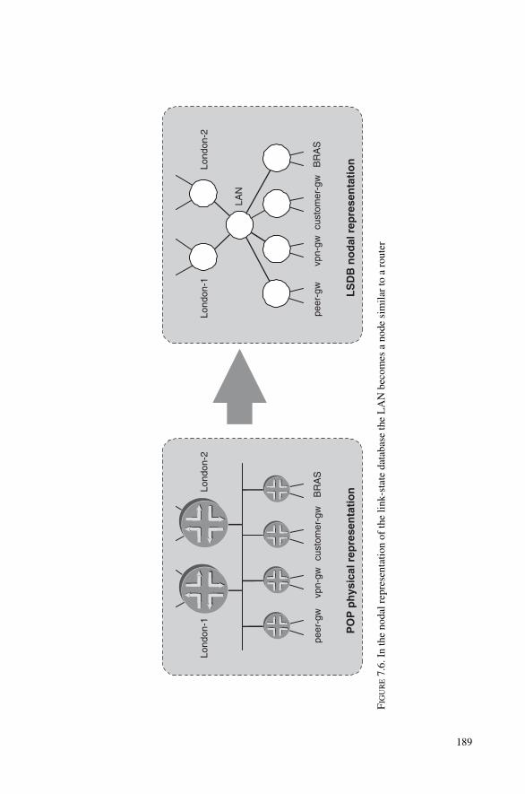
PO
P p
hys
ical
rep
rese
nta
tio
n
Lond
on-1
Lond
on-2
peer
-gw
vpn-
gwcu
stom
er-g
wB
RA
S
LS
DB
no
dal
rep
rese
nta
tio
n
Lond
on-1
Lond
on-2
peer
-gw
vpn-
gwcu
stom
er-g
wB
RA
S
LAN
FIG
UR
E7.
6. I
n th
e no
dal r
epre
sent
atio
n of
the
link-
stat
e da
taba
se th
e L
AN
bec
omes
a n
ode
sim
ilar
to a
rou
ter
189

the LAN have to report. The original O(N2) scaling property turns into a O(N) scalingbehaviour. The LSP dynamics are improved as well. Once a new router comes online anddeclares the adjacency with the DIS up only two new LSPs will be generated.
In the tcpdump output you can see that after processing the adjacency only two newLSPs are generated. The first LSP is the pseudonode and contains the LAN to Router #3IS Reachability. The second LSP describes the Router #3 to LAN Reachability.
Tcpdump outputOn this LAN there is an established adjacency between Router #1 and #2. Next, Router#3 comes online and after processing all the 3-way handshake and padding procedurestwo new LSPs are generated.
17:37:45.769638 OSI, IS-IS, L1 CSNP, src-id 0000.0000.0001, length 99
17:37:45.799403 OSI, IS-IS, L1 Lan IIH, src-id 0000.0000.0001, lan-id
0000.0000.0001.02, prio 120, length 56
17:37:48.619494 OSI, IS-IS, L1 Lan IIH, src-id 0000.0000.0001, lan-id
0000.0000.0001.02, prio 120, length 56
17:37:50.204522 OSI, IS-IS, L1 Lan IIH, src-id 0000.0000.0002, lan-id
0000.0000.0001.02, prio 65, length 74
17:37:51.089607 OSI, IS-IS, L1 Lan IIH, src-id 0000.0000.0001, lan-id
0000.0000.0001.02, prio 120, length 56
17:37:51.273316 OSI, IS-IS, L1 Lan IIH, src-id 0000.0000.0003, lan-id
0000.0000.0003.02, prio 64, length 78
17:37:51.276579 OSI, IS-IS, L1 Lan IIH, src-id 0000.0000.0001, lan-id
0000.0000.0001.02, prio 120, length 1492
17:37:51.278286 OSI, IS-IS, L1 Lan IIH, src-id 0000.0000.0002, lan-id
0000.0000.0001.02, prio 65, length 1492
17:37:51.282142 OSI, IS-IS, L1 Lan IIH, src-id 0000.0000.0003, lan-id
0000.0000.0003.02, prio 64, length 1492
[ … ]
17:37:51.364655 OSI, IS-IS, L1 Lan IIH, src-id 0000.0000.0002, lan-id
0000.0000.0001.02, prio 65, length 1492
17:37:51.365221 OSI, IS-IS, L1 Lan IIH, src-id 0000.0000.0001, lan-id
0000.0000.0001.02, prio 120, length 1492
17:37:51.367212 OSI, IS-IS, L1 Lan IIH, src-id 0000.0000.0003, lan-id
0000.0000.0001.02, prio 64, length 1492
17:37:51.370734 OSI, IS-IS, L1 Lan IIH, src-id 0000.0000.0001, lan-id
0000.0000.0001.02, prio 120, length 62
17:37:51.374205 OSI, IS-IS, L1 Lan IIH, src-id 0000.0000.0002, lan-id
0000.0000.0001.02, prio 65, length 80
17:37:51.374484 OSI, IS-IS, L1 Lan IIH, src-id 0000.0000.0003, lan-id
0000.0000.0001.02, prio 64, length 92
17:37:51.376143 OSI, IS-IS, L1 Lan IIH, src-id 0000.0000.0001, lan-id
0000.0000.0001.02, prio 120, length 62
17:37:51.379266 OSI, IS-IS, L1 Lan IIH, src-id 0000.0000.0002, lan-id
0000.0000.0001.02, prio 65, length 80
190 7. Pseudonodes and Designated Routers
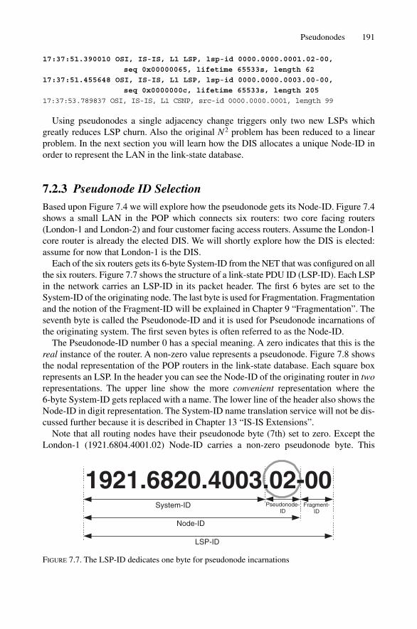
17:37:51.390010 OSI, IS-IS, L1 LSP, lsp-id 0000.0000.0001.02-00,
seq 0x00000065, lifetime 65533s, length 62
17:37:51.455648 OSI, IS-IS, L1 LSP, lsp-id 0000.0000.0003.00-00,
seq 0x0000000c, lifetime 65533s, length 205
17:37:53.789837 OSI, IS-IS, L1 CSNP, src-id 0000.0000.0001, length 99
Using pseudonodes a single adjacency change triggers only two new LSPs whichgreatly reduces LSP churn. Also the original N2 problem has been reduced to a linearproblem. In the next section you will learn how the DIS allocates a unique Node-ID inorder to represent the LAN in the link-state database.
7.2.3 Pseudonode ID SelectionBased upon Figure 7.4 we will explore how the pseudonode gets its Node-ID. Figure 7.4shows a small LAN in the POP which connects six routers: two core facing routers(London-1 and London-2) and four customer facing access routers. Assume the London-1core router is already the elected DIS. We will shortly explore how the DIS is elected:assume for now that London-1 is the DIS.
Each of the six routers gets its 6-byte System-ID from the NET that was configured on allthe six routers. Figure 7.7 shows the structure of a link-state PDU ID (LSP-ID). Each LSPin the network carries an LSP-ID in its packet header. The first 6 bytes are set to theSystem-ID of the originating node. The last byte is used for Fragmentation. Fragmentationand the notion of the Fragment-ID will be explained in Chapter 9 “Fragmentation”. Theseventh byte is called the Pseudonode-ID and it is used for Pseudonode incarnations ofthe originating system. The first seven bytes is often referred to as the Node-ID.
The Pseudonode-ID number 0 has a special meaning. A zero indicates that this is thereal instance of the router. A non-zero value represents a pseudonode. Figure 7.8 showsthe nodal representation of the POP routers in the link-state database. Each square boxrepresents an LSP. In the header you can see the Node-ID of the originating router in tworepresentations. The upper line show the more convenient representation where the 6-byte System-ID gets replaced with a name. The lower line of the header also shows theNode-ID in digit representation. The System-ID name translation service will not be dis-cussed further because it is described in Chapter 13 “IS-IS Extensions”.
Note that all routing nodes have their pseudonode byte (7th) set to zero. Except theLondon-1 (1921.6804.4001.02) Node-ID carries a non-zero pseudonode byte. This
Pseudonodes 191
System-ID Pseudonode-ID
Fragment-ID
1921.6820.4003.02-00
Node-ID
LSP-ID
FIGURE 7.7. The LSP-ID dedicates one byte for pseudonode incarnations

Lo
nd
on
PO
P
Lond
on-1
Lond
on-2
peer
-gw
vpn-
gwcu
stom
er-g
wB
RA
S
IS R
each
abili
ty T
LV
Lond
on-1
.00
LS
P19
21.6
804.
4001
.00
cost
10
Lond
on-1
.02
peer
-gw
.00
LS
P19
21.6
804.
4012
.00
Lond
on-2
.00
LS
P19
21.6
804.
4002
.00
vpn-
gw.0
0L
SP
1921
.680
4.40
10.0
0
cust
omer
-gw
.00
LS
P19
21.6
804.
4010
.00
BR
AS
.00
LS
P19
21.6
804.
4011
.00
IS R
each
abili
ty T
LV
Lond
on-1
.02
LS
P19
21.6
804.
4001
.02
cost
0co
st 0
cost
0co
st 0
cost
0co
st 0
Lond
on-1
.00
Lond
on-2
.00
peer
-gw
.00
vpn-
gw.0
0cu
stom
er-g
w.0
0B
RA
S.0
0
IS R
each
abili
ty T
LV co
st 1
0Lo
ndon
-1.0
2
IS R
each
abili
ty T
LV co
st 1
0Lo
ndon
-1.0
2IS
Rea
chab
ility
TL
V cost
10
Lond
on-1
.02
IS R
each
abili
ty T
LV co
st 1
0Lo
ndon
-1.0
2IS
Rea
chab
ility
TL
V cost
10
Lond
on-1
.02
FIG
UR
E7.
8. T
he p
seud
onod
e bo
rrow
sth
e Sy
stem
-ID
fro
m th
e D
IS
192
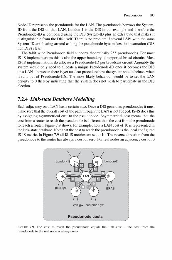
Node-ID represents the pseudonode for the LAN. The pseudonode borrows the System-ID from the DIS on that LAN. London-1 is the DIS in our example and therefore thePseudonode-ID is composed using the DIS System-ID plus an extra byte that makes itdistinguishable from the DIS itself. There is no problem if several LSPs with the sameSystem-ID are floating around as long the pseudonode byte makes the incarnation (DISnon DIS) clear.
The 8-bit wide Pseudonode field supports theoretically 255 pseudonodes. For most IS-IS implementations this is also the upper boundary of supported broad circuits. MostIS-IS implementations do allocate a Pseudonode-ID per broadcast circuit. Arguably thesystem would only need to allocate a unique Pseudonode-ID once it becomes the DIS on a LAN – however, there is yet no clear procedure how the system should behave whenit runs out of Pseudonode-IDs. The most likely behaviour would be to set the LAN priority to 0 thereby indicating that the system does not wish to participate in the DISelection.
7.2.4 Link-state Database ModellingEach adjacency on a LAN has a certain cost. Once a DIS generates pseudonodes it mustmake sure that the overall cost of the path through the LAN is not fudged. IS-IS does thisby assigning asymmetrical cost to the pseudonode. Asymmetrical cost means that thecost from a router to reach the pseudonode is different than the cost from the pseudonodeto reach a router. Figure 7.9 shows, for example, how a LAN cost of 10 is represented inthe link-state database. Note that the cost to reach the pseudonode is the local configuredIS-IS metric. In Figure 7.9 all IS-IS metrics are set to 10. The reverse direction from thepseudonode to the router has always a cost of zero. For real nodes an adjacency cost of 0
Pseudonodes 193
Pseudonode costs
London-1 London-2
peer-gw
vpn-gw customer-gw
BRAS
LAN
1010
10
1010
10 0
00
0
00
FIGURE 7.9. The cost to reach the pseudonode equals the link cost – the cost from the pseudonode to the real node is always zero
is an illegal value, accept for pseudonodes. You will see later in Chapter 10 “SPF andRoute Calculation” that the pseudonode needs a special treatment during the SPF calcu-lation because of those zero cost adjacencies.
The cost of adjacencies can be checked on the router’s command line interface. Youcan check the cost between the Nodes using the show isis database detailcommand:
JUNOS command outputThe JUNOS show isis database detail command displays how the routers are linkedto the pseudonodes. The IOS command show isis database detail provides a sim-ilar output.
hannes@Stockholm> show isis database detail
IS-IS level 1 link-state database:
Amsterdam.00-00 Sequence: 0x187, Checksum: 0xbda7,
Lifetime: 59556 secs
IS neighbor: Stockholm.02 Metric: 10
IP prefix: 172.16.1.0/24 Metric: 0 Internal Up
IP prefix: 192.168.1.1/32 Metric: 0 Internal Up
The first node is a real router carrying the Amsterdam.00 Node-ID. The router islinked to a Pseudonode Stockholm.02. Note the cost of 10 to reach the pseudonode.
Stockholm.00-00 Sequence: 0x2e, Checksum: 0x7157,
Lifetime: 59554 secs
IS neighbor: Stockholm.02 Metric: 10
IP prefix: 172.16.0.4/24 Metric: 0 Internal Up
IP prefix: 192.168.1.2/32 Metric: 0 Internal Up
The second node is a real router carrying the Stockholm.00 Node-ID. The router isalso linked to the Stockholm.02 Pseudonode. Note the cost of 10 to reach the pseudonode.
Stockholm.02-00 Sequence: 0x69, Checksum: 0x2d26,
Lifetime: 59556 secs
IS neighbor: Amsterdam.00 Metric: 0
IS neighbor: Stockholm.00 Metric: 0
The third node is a pseudonode carrying the Stockholm.02 Node-ID. Note the zerocost which connects the pseudonode back to the two real routers. The pseudonode alsodoes not carry any higher-level protocol information like IP addresses. The pseudonodecan be seen as a protocol independent node which only carries IS-Reach and optionalauthentication information. Arguably the notion of protocol independence matches alsothe physical setup: the pseudonode represents a LAN and a LAN can carry any Layer-3protocol.
194 7. Pseudonodes and Designated Routers

Eth
ern
etA
mst
erd
am.0
0S
tock
ho
lm.0
0
Sto
ckh
olm
.00
Am
ster
dam
.00
LA
N
Sto
ckh
olm
.00
Am
ster
dam
.00
Sto
ckh
olm
.02
FIG
UR
E7.
10.
Two
rout
ers
conn
ecte
d by
an
Eth
erne
t lin
k ca
n be
rep
rese
nted
in tw
o w
ays
in th
e IS
-IS
link
stak
e da
taba
se
195

196 7. Pseudonodes and Designated Routers
Pseudonodes were intended to relieve routers from additional processing overhead.However, there are deployment scenarios where the generation and maintenance of apseudonode generates more overhead than the original point-to-point behaviour.
7.2.5 Pseudonode Suppression on p2p LANsWith the rise of Gigabit Ethernet (GE) the once for-access-only media has become acheap and fast router-to-router pipe. The overall cost of transmission for a Gigabit Ethernetpipe is lower than for a pipe which was the major driver that GE is being deployed in p2pfashion. Historically, transmission of the odd sized (in the sense that it does not fitexactly in the SONET/SDH digital hierarchy) Gigabit Frames turned out to be an expen-sive operation. Today there are affordable DWDM systems available that allow a serviceprovider to multiplex dozens of GE pipes on a single fibre.
The mandate to generate a pseudonode on the LAN circuit even if there are just two speakers on a LAN seems to be a useless exercise. Consider Figure 7.10 which illus-trates how two routers connected by a p2p broadcast circuit need to generate a third nodein order to represent the LAN in the link-state database. The nodal graph is shown in thetop left corner. It is evident that for just two routers pseudonode generation is more thana overhead than a contribution to scaling LAN adjacencies, which was the original goalof pseudonodes. In the IETF the idea of pseudonode suppression has been born. Internetdraft draft-ietf-isis-igp-p2p-over-lan-03 gives describes a method to avoid sending thepseudonode generation.
How can a system avoid generating a pseudonode by not breaking things? The idea ofthe draft is simple: Just send a p2p Hello encapsulated in an Ethernet frame. Recall thep2p PDU type is only used on p2p media like ATM, POS or Frame Relay. If a p2p-IIH isencapsulated in an Ethernet frame and both sides agree to suppress the pseudonode thenno DIS election and subsequently no pseudonode generation needs to be executed.
The tcpdump output shows the odd frame. First the frame is sent to the MAC addressAll-IS (09.00:2b:00:00:05). Normally this MAC address is never used as the L1-LAN-IIH and L2-LAN-IIH is sent to the ALL-L1-IS (01:80:C2:00:00:14) and All-L2-IS(01:80:C2:00:00:15) functional MAC address. Next the PDU type is the p2p IIH whichis otherwise never used on LAN circuits. Finally there is the p2p Adjacency State TLVwhich is also sent on p2p circuits only. Recall on LAN media the IS Neighbour TLV #6is typically used for the 3-way handshake.
Tcpdump outputIf an isis interface is marked as point-to-point then the router will pack a p2pHello containing p2p relevant TLVs on the Ethernet frame and ship it to the All-IS LANmulticast Address.
23:41:19.490748 00:90:69:b2:58:2d > 09:00:2b:00:00:05, OSI, IS-IS, length: 58
p2p IIH, hlen: 20, v: 1, pdu-v: 1, sys-id-len: 6 (0), max-area: 3 (0)
source-id: 0000.0000.0002, holding time: 27s, Flags: [Level 1, Level 2]
circuit-id: 0x01, PDU length: 58

Point-to-point Adjacency State TLV #240, length: 15
Adjacency State: Up (0)
Extended Local circuit-ID: 0x00000041
Neighbor System-ID: 0000.0000.0003
Neighbor Extended Local circuit-ID: 0x0000005e
Protocols supported TLV #129, length: 2
NLPID(s): IPv4 (0xcc), IPv6 (0x8e)
IPv4 Interface address(es) TLV #132, length: 4
IPv4 interface address: 172.16.0.5
Area address(es) TLV #1, length: 4
Area address (length: 3): 49.0001
Restart Signaling TLV #211, length: 3
Flags [none], Remaining holding time 0s
Both IOS and JUNOS support pseudonode suppression. In JUNOS you need to configure the point-to-point keyword inside the protocol isis interface{} stanza.
JUNOS configurationIn JUNOS pseudonode suppression is activated by adding the point-to-point keywordinside the protocols isis interface {} stanza.
hannes@Stockholm> show configuration
[ … ]
protocols {
isis {
[ … ]
interface ge-2/2/0.0 {
point-to-point;
}
interface lo0.0;
}
}
You can verify if the circuit was assigned to be a p2p media using the show isisinterface command.
JUNOS command outputOnce a broadcast circuit is configured for pseudonode suppression the Point to Pointflag is listed instead of the DIS.
hannes@Stockholm> show isis interface
IS-IS interface database:
Interface L CirID Level 1 DR Level 2 DR L1/L2 Metric
[ … ]
ge-2/2/0.0 3 0x1 Point to Point Point to Point 10000/10000
lo0.0 0 0x1 Passive Passive 0/0
Pseudonodes 197

The IOS configuration is similar to JUNOS. Pseudonode suppression is once again aninterface property and can be configured using the isis network point-to-point configuration statement.
IOS configurationThe IOS configuration requires the isis network point-to-point statement to sup-press pseudonodes.
Amsterdam# show running-config
[ … ]
!
interface GigabitEthernet0/0
ip address 172.16.26.170 255.255.255.0
ip router isis
[ … ]
isis network point-to-point
!
Unfortunately there is no explicit hint in IOS to display if the interface is actually run-ning in p2p mode. The only difference to a regular broadcast interface is that the DR IDline is missing in the output.
IOS command outputOn a point-to-point network configuration the output of the show clns interface com-mand does omit the DR IDs.
Amsterdam#show clns interface GigabitEthernet0/0
GigabitEthernet0/0 is up, line protocol is up
Checksums enabled, MTU 1497, Encapsulation SAP
ERPDUs enabled, min. interval 10 msec.
CLNS fast switching disabled
CLNS SSE switching disabled
DEC compatibility mode OFF for this interface
Next ESH/ISH in 30 seconds
Routing Protocol: IS-IS
Circuit Type: level-1-2
Interface number 0x6, local circuit ID 0x2
Neighbor System-ID: Stockholm
Level-1 Metric: 10, Priority: 64, Circuit ID: Amsterdam.02
Number of active level-1 adjacencies: 1
Neighbor System-ID: Stockholm
Level-2 Metric: 10, Priority: 64, Circuit ID: Amsterdam.02
Number of active level-2 adjacencies: 1
Next IS-IS LAN Level-1 Hello in 2 seconds
Next IS-IS LAN Level-2 Hello in 1 seconds
Another possibility is actually looking at the link-state database if one of the tworouters on the LAN generates a pseudonode.
198 7. Pseudonodes and Designated Routers

IOS command outputThe database output shows that there is no pseudonode generated by either theStockholm or Amsterdam router in the database. Additional evidence is that the tworouters did link their adjacencies directly (targeting the .00 incarnation) to each other.
Amsterdam#show isis database detail
IS-IS Level-1 Link State Database
LSPID LSP Seq Num LSP Checksum LSP Holdtime ATT/P/OL
Amsterdam.00-00 * 0x0000019A 0xF613 818 0/0/0
Area Address: 49.0001
NLPID: 0xCC
Router ID: 192.168.1.17
IP Address: 192.168.1.17
Hostname: Amsterdam
Metric: 10 IS-Extended Stockholm.00
Metric: 10 IP 172.16.1.0/24
Metric: 0 IP 192.168.1.17/32
Stockholm.00-00 0x0000c1E9 0xE448 414 0/0/0
Area Address: 49.0001
NLPID: 0xCC
Hostname: Stockholm
Router ID: 192.168.1.8
IP Address: 192.168.1.8
Metric: 10 IS-Extended Amsterdam.00
Metric: 10 IP 172.16.1.0/24
Metric: 0 IP 192.168.1.8/32
The output reveals that no pseudonode is in the database and two routers are linkeddirectly to each other as shown in the top right corner of Figure 7.10.
If we allow pseudonode generation then we have silently assumed so far that there isa DIS on the LAN that generates the pseudonode on behalf of the LAN. Before that hap-pens a DIS needs to get elected. The following paragraph describes DIS election proced-ures and timing.
7.3 DIS and DIS Election Procedure
The good news is that the DIS election procedure is a very simple process. Due to its state-less nature a receiving router can immediately determine the DIS on the LAN. For DISelections there are two fields in the LAN IIH header (see Figure 5.2) that are relevant:
• Priority field in the LAN-IIH• The Source SNPA (�MAC address) of the sender
The Priority field is 7-bits wide and therefore Priority values between 0 and 127 canbe configured. A Priority value of zero means that this system does not wish to becomea DIS at all. In case there are many routers with the same Priority competing for the DIS
DIS and DIS Election Procedure 199

then the Source SNPA (� the MAC address) tie breaks. The system with the numericallyhighest source MAC address then wins the beauty contest.
Each router computes the DIS locally after receipt of IIH messages by comparing itagainst its current DIS Priority and SNPA. For debugging purposes there is also a field inthe LAN-IIH where each router on a LAN writes its current DIS belief.
7.3.1 Pre-emptionThe DIS is pre-emptive. That means, if a router with a higher Priority comes online itimmediately resigns from DIS ownership. To document that it has resigned it puts thewinning router’s Node-ID in its LAN-ID field. The following tcpdump output shows anexample of how a router changes its LAN Priority and commences DIS ownership.
Tcpdump output21:51:17.716553 OSI, IS-IS, L1 Lan IIH, src-id 0000.0000.0002, lan-id
0000.0000.0002.02, prio 65, length 74
21:51:19.813231 OSI, IS-IS, L1 Lan IIH, src-id 0000.0000.0001, lan-id
0000.0000.0002.02, prio 64, length 56
21:51:20.583435 OSI, IS-IS, L1 Lan IIH, src-id 0000.0000.0002, lan-id
0000.0000.0002.02, prio 65, length 74
21:51:22.557163 OSI, IS-IS, L1 CSNP, src-id 0000.0000.0002, length 83
21:51:23.516664 OSI, IS-IS, L1 Lan IIH, src-id 0000.0000.0002, lan-id
0000.0000.0002.02, prio 65, length 74
21:51:24.193870 OSI, IS-IS, L1 Lan IIH, src-id 0000.0000.0001, lan-id
0000.0000.0001.02, prio 120, length 56
Router #1 changes the LAN priority from 64 to 120, and becomes the highestPriority router on the LAN
21:51:24.196787 OSI, IS-IS, L1 Lan IIH, src-id 0000.0000.0002, lan-id
0000.0000.0001.02, prio 65, length 74
21:51:24.197468 OSI, IS-IS, L1 LSP, lsp-id 0000.0000.0002.02-00, seq
0x00000017, lifetime 0s, length 43
Router #2 resigns and purges the old pseudonode
21:51:24.220793 OSI, IS-IS, L1 LSP, lsp-id 0000.0000.0002.00-00, seq
0x0000001b, lifetime 1199s, length 158
21:51:24.444682 OSI, IS-IS, L1 LSP, lsp-id 0000.0000.0001.00-00, seq
0x00000120, lifetime 1198s, length 210
21:51:24.473860 OSI, IS-IS, L1 LSP, lsp-id 0000.0000.0001.02-00, seq
0x00000004, lifetime 1198s, length 76
Router #1 & #2 re-link their LSPs to the new pseudonode
21:51:24.484541 OSI, IS-IS, L1 Lan IIH, src-id 0000.0000.0001, lan-id
0000.0000.0001.02, prio 120, length 56
21:51:26.773307 OSI, IS-IS, L1 Lan IIH, src-id 0000.0000.0001, lan-id
0000.0000.0001.02, prio 120, length 56
200 7. Pseudonodes and Designated Routers
21:51:29.373384 OSI, IS-IS, L1 Lan IIH, src-id 0000.0000.0001, lan-id
0000.0000.0001.02, prio 120, length 56
21:51:30.963776 OSI, IS-IS, L1 Lan IIH, src-id 0000.0000.0002, lan-id
0000.0000.0001.02, prio 65, length 74
21:51:31.773442 OSI, IS-IS, L1 Lan IIH, src-id 0000.0000.0001, lan-id
0000.0000.0001.02, prio 120, length 56
21:51:32.893696 OSI, IS-IS, L1 CSNP, src-id 0000.0000.0001, length 83
The new DIS (Router #1) sends a full CSNP report
7.3.2 PurgingAfter Router #2 resigns from ownership it purges its pseudonode. Purging means remov-ing from the database. A new DIS has been elected and therefore the DIS wants to cleanup its remnants.
A purged LSP contains nothing but the LSP header (and optionally authenticationinformation if configured). Both the Lifetime and Checksum fields are set to zero. Bothare illegal values. The Fletcher Checksumming Algorithm and the Lifetime can neverbecome zero for a regular LSP packet.
Tcpdump outputA purged pseudonode LSP contains nothing but the LSP header and the Checksum andLifetime fields are set to zero.
01:34:01.544481 OSI, IS-IS, length: 43
L1 LSP, hlen: 27, v: 1, pdu-v: 1, sys-id-len: 6 (0), max-area: 3 (0)
lsp-id: 0000.0000.0002.02-00, seq: 0x00000001, lifetime: 0s
chksum: 0x0000 (purged), PDU length: 27, L1L2 IS
Purging is described in more detail in Chapter 6 “Generating, Flooding and AgeingLSPs”.
The DIS ID can be easily spotted on JUNOS routers using the show isis inter-face detail command.
JUNOS command outputThe last column of the show isis interface detail output lists the designated routersfor each level on that LAN circuit.
hannes@Stockholm> show isis interface detail
IS-IS interface database:
ge-2/2/0.0
Index: 64, State: 0x6, Circuit id: 0x2, Circuit type: 3
LSP interval: 100 ms, CSNP interval: 10 s
DIS and DIS Election Procedure 201
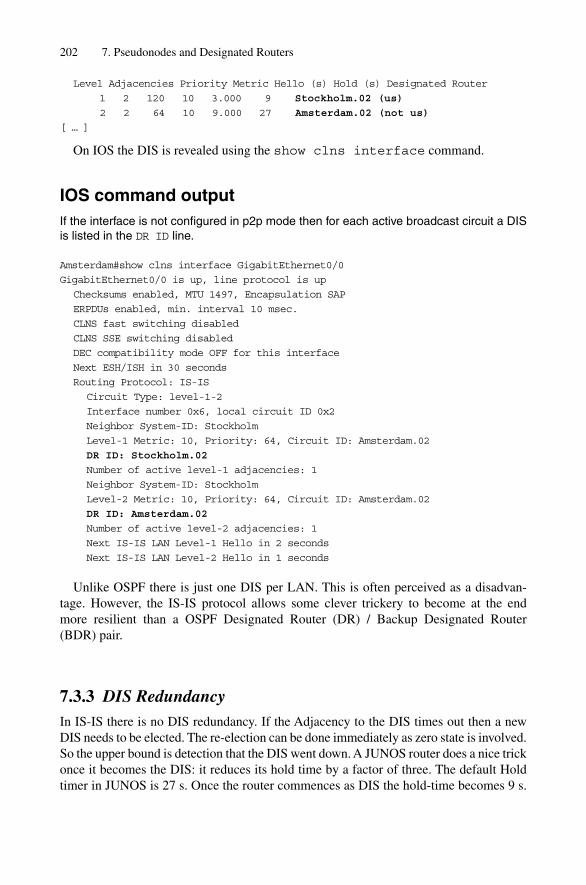
Level Adjacencies Priority Metric Hello (s) Hold (s) Designated Router
1 2 120 10 3.000 9 Stockholm.02 (us)
2 2 64 10 9.000 27 Amsterdam.02 (not us)
[ … ]
On IOS the DIS is revealed using the show clns interface command.
IOS command outputIf the interface is not configured in p2p mode then for each active broadcast circuit a DISis listed in the DR ID line.
Amsterdam#show clns interface GigabitEthernet0/0
GigabitEthernet0/0 is up, line protocol is up
Checksums enabled, MTU 1497, Encapsulation SAP
ERPDUs enabled, min. interval 10 msec.
CLNS fast switching disabled
CLNS SSE switching disabled
DEC compatibility mode OFF for this interface
Next ESH/ISH in 30 seconds
Routing Protocol: IS-IS
Circuit Type: level-1-2
Interface number 0x6, local circuit ID 0x2
Neighbor System-ID: Stockholm
Level-1 Metric: 10, Priority: 64, Circuit ID: Amsterdam.02
DR ID: Stockholm.02
Number of active level-1 adjacencies: 1
Neighbor System-ID: Stockholm
Level-2 Metric: 10, Priority: 64, Circuit ID: Amsterdam.02
DR ID: Amsterdam.02
Number of active level-2 adjacencies: 1
Next IS-IS LAN Level-1 Hello in 2 seconds
Next IS-IS LAN Level-2 Hello in 1 seconds
Unlike OSPF there is just one DIS per LAN. This is often perceived as a disadvan-tage. However, the IS-IS protocol allows some clever trickery to become at the end more resilient than a OSPF Designated Router (DR) / Backup Designated Router (BDR) pair.
7.3.3 DIS RedundancyIn IS-IS there is no DIS redundancy. If the Adjacency to the DIS times out then a newDIS needs to be elected. The re-election can be done immediately as zero state is involved.So the upper bound is detection that the DIS went down. A JUNOS router does a nice trickonce it becomes the DIS: it reduces its hold time by a factor of three. The default Holdtimer in JUNOS is 27 s. Once the router commences as DIS the hold-time becomes 9 s.
202 7. Pseudonodes and Designated Routers

Because of the hard-coded Hello-Multiplier of 3 the Hellos are scheduled at 3-secondintervals. There is no similar function in the IOS Implementation of IS-IS.
Tcpdump outputThe DIS (0000.0000.0001.02) sends its Hellos three times as fast as the other router.
02:40:10.009492 OSI, IS-IS, L1 Lan IIH, src-id 0000.0000.0001,
lan-id 0000.0000.0001.02, prio 120, length 62
02:40:12.879672 OSI, IS-IS, L1 Lan IIH, src-id 0000.0000.0001,
lan-id 0000.0000.0001.02, prio 120, length 62
02:40:15.509631 OSI, IS-IS, L1 Lan IIH, src-id 0000.0000.0001,
lan-id 0000.0000.0001.02, prio 120, length 62
02:40:16.227864 OSI, IS-IS, L1 Lan IIH, src-id 0000.0000.0002,
lan-id 0000.0000.0001.02, prio 65, length 80
02:40:17.789689 OSI, IS-IS, L1 Lan IIH, src-id 0000.0000.0001,
lan-id 0000.0000.0001.02, prio 120, length 62
02:40:20.239755 OSI, IS-IS, L1 Lan IIH, src-id 0000.0000.0001,
lan-id 0000.0000.0001.02, prio 120, length 62
02:40:22.619829 OSI, IS-IS, L1 Lan IIH, src-id 0000.0000.0001,
lan-id 0000.0000.0001.02, prio 120, length 62
02:40:23.847965 OSI, IS-IS, L1 Lan IIH, src-id 0000.0000.0002,
lan-id 0000.0000.0001.02, prio 65, length 80
02:40:24.889888 OSI, IS-IS, L1 Lan IIH, src-id 0000.0000.0001,
lan-id 0000.0000.0001.02, prio 120, length 62
02:40:27.429931 OSI, IS-IS, L1 Lan IIH, src-id 0000.0000.0001,
lan-id 0000.0000.0001.02, prio 120, length 62
02:40:29.690077 OSI, IS-IS, L1 Lan IIH, src-id 0000.0000.0001,
lan-id 0000.0000.0001.02, prio 120, length 62
02:40:31.828099 OSI, IS-IS, L1 Lan IIH, src-id 0000.0000.0002,
lan-id 0000.0000.0001.02, prio 65, length 80
The DIS is tuning itself to provide faster resiliency. With 9 seconds of detecting thatthe DIS is broken and no state for the re-election IS-IS is far more superior than OSPFeven without a Backup Designated Router. The DIS convergence is only dependend of thedead interval (hold-timer) of the old DIS. Unlike IS-IS, OSPF cannot set its dead-intervalto an arbitrary value because all those values need to match on a given LAN. Arguablyone could tune down all the OSPF Hello and Dead timers but that would increase thestress on the LAN by a factor of three to get comparable results.
7.4 Summary
Broadcast interfaces like Ethernet are becoming increasingly popular as router-to-routerlink technology. Both multipoint and point-to-point setups have unique requirements tothe IS-IS protocol. In a multipoint environment careful Hello scheduling and applying ofjitter needs to be performed to avoid peak-stress through self-synchronization. Because
DIS and DIS Election Procedure 203

of storage requirements and LSP churn avoidance the LAN needs to get nodal represen-tation as a pseudonode. The pseudonode is deterministically elected and generates thepseudonode on behalf the LAN circuit which cannot speak for itself.
In multipoint setups the pseudonode functionality generates more overhead than gainand is often required to be turned off. A recent Internet draft describes how to build point-to-point adjacency on a 2-party LAN circuit without pseudonode generation.
204 7. Pseudonodes and Designated Routers

9
Fragmentation
Modern communication relies on packet networks. On each layer in the OSI referencemodel a message from higher layers needs to get packetized by lower layers. The under-lying packet switching hardware that finally transports the frames across the Internet hasmost certain packet size constraints. Ethernet is a good example for these constraints, bynot allowing individual packets to be bigger than 1518 bytes. Each layer in the OSIReference Model needs to deal with the fundamental question: how will messages that donot fit the transport circuit packet be transported? In this chapter you will see some exam-ples how IP and the IS-IS routing protocol solves the underlying problem by choppingmessages into pieces and reassembling them at the receiver. Additionally the side effects ofsuch chopping and reassembly techniques, which have been observed in big operationalnetworks, will be highlighted.
9.1 Fragmentation and the OSI Reference Model
The OSI Reference Model relies on a layering technique. The purpose of the layeringarchitecture is to hide the actual packet transport infrastructure from the driving application.The result is that the application does not need to care what packet-switching hardware, evenwhat network protocol is used to convey the applications message as long as the receiveron the other end can de-multiplex the layering of message. The Transmission ControlProtocol (TCP) is a good example for this. Figure 9.1 shows an example application likethe Simple Mail Transfer Protocol (SMTP). SMTP relies on TCP for doing end-to-endflow control, re-sequencing and retransmission. TCP is dependent on a networking pro-tocol like IPv4 or IPv6 to get packets finally relayed from Client A to Server B. Duringits journey from Client A to Client B the packet will be transported using various layersof Layer-2 transport networks such as (but not limited to) Ethernet, SONET/SDH, FrameRelay, ATM.
If you take a look how the original message (the email) is packaged into finally Ethernet,or SONET/SDH frames, you will notice that the message first is split by the transport pro-tocol. Splitting the original application stream is necessary to get packets from streamswhich finally get packaged and repackaged several times. Think of it like putting a letter inan envelope, which is then put in a larger envelope, which is put in a larger envelope untilthe packet finally gets delivered. The envelope analogy works also when it comes down toframe sizes. When you want to put a message in an envelope then the envelope has to belarger for the message to fit into.
223
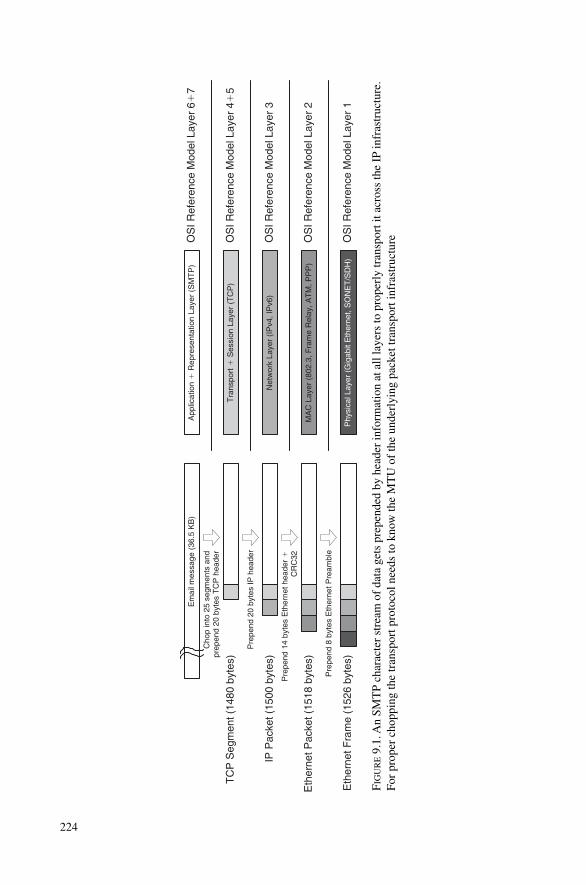
OS
I Ref
eren
ce M
odel
Lay
er 2
Net
wor
k La
yer
(IP
v4, I
Pv6
)
Tra
nspo
rt�
Ses
sion
Lay
er (
TC
P)
MA
C L
ayer
(80
2.3,
Fra
me
Rel
ay, A
TM
, PP
P)
Phy
sica
l Lay
er (
Gig
abit
Eth
erne
t, S
ON
ET
/SD
H)
OS
I Ref
eren
ce M
odel
Lay
er 1
App
licat
ion
� R
epre
sent
atio
n La
yer
(SM
TP
)
OS
I Ref
eren
ce M
odel
Lay
er 3
OS
I Ref
eren
ce M
odel
Lay
er 4
�5
OS
I Ref
eren
ce M
odel
Lay
er 6
�7
Em
ail m
essa
ge (
36.5
KB
)
Cho
p in
to 2
5 se
gmen
ts a
ndpr
epen
d 20
byt
es T
CP
hea
der
Pre
pend
20
byte
s IP
hea
der
Pre
pend
14
byte
s E
ther
net h
eade
r �
CR
C32
Pre
pend
8 b
ytes
Eth
erne
t Pre
ambl
e
IP P
acke
t (15
00 b
ytes
)
TC
P S
egm
ent (
1480
byt
es)
Eth
erne
t Pac
ket (
1518
byt
es)
Eth
erne
t Fra
me
(152
6 by
tes)
FIG
UR
E9.
1. A
n SM
TP
char
acte
r st
ream
of
data
get
s pr
epen
ded
by h
eade
r in
form
atio
n at
all
laye
rs to
pro
perl
y tr
ansp
ort i
t acr
oss
the
IP in
fras
truc
ture
.Fo
r pr
oper
cho
ppin
g th
e tr
ansp
ort p
roto
col n
eeds
to k
now
the
MT
U o
f th
e un
derl
ying
pac
k et t
rans
port
infr
astr
uctu
re
224
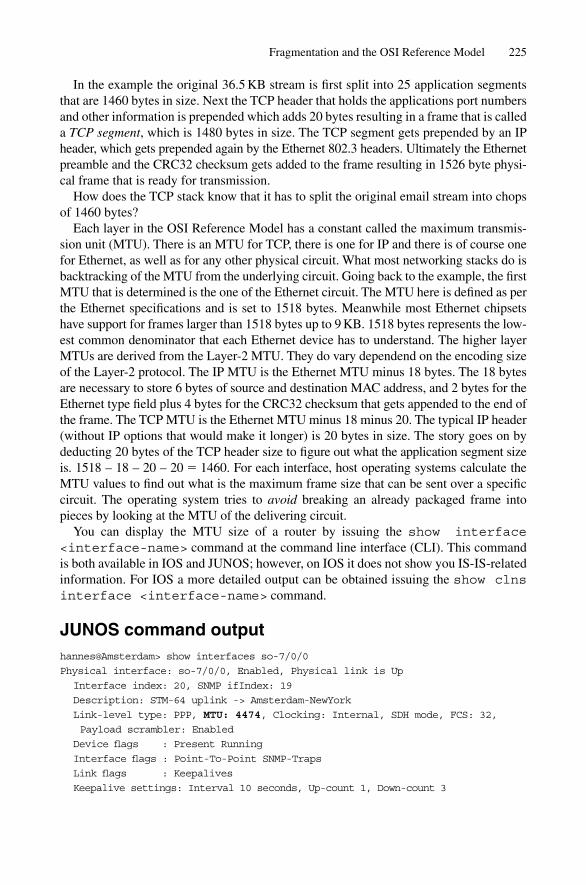
In the example the original 36.5 KB stream is first split into 25 application segmentsthat are 1460 bytes in size. Next the TCP header that holds the applications port numbersand other information is prepended which adds 20 bytes resulting in a frame that is calleda TCP segment, which is 1480 bytes in size. The TCP segment gets prepended by an IPheader, which gets prepended again by the Ethernet 802.3 headers. Ultimately the Ethernetpreamble and the CRC32 checksum gets added to the frame resulting in 1526 byte physi-cal frame that is ready for transmission.
How does the TCP stack know that it has to split the original email stream into chopsof 1460 bytes?
Each layer in the OSI Reference Model has a constant called the maximum transmis-sion unit (MTU). There is an MTU for TCP, there is one for IP and there is of course onefor Ethernet, as well as for any other physical circuit. What most networking stacks do isbacktracking of the MTU from the underlying circuit. Going back to the example, the firstMTU that is determined is the one of the Ethernet circuit. The MTU here is defined as perthe Ethernet specifications and is set to 1518 bytes. Meanwhile most Ethernet chipsetshave support for frames larger than 1518 bytes up to 9 KB. 1518 bytes represents the low-est common denominator that each Ethernet device has to understand. The higher layerMTUs are derived from the Layer-2 MTU. They do vary dependend on the encoding sizeof the Layer-2 protocol. The IP MTU is the Ethernet MTU minus 18 bytes. The 18 bytesare necessary to store 6 bytes of source and destination MAC address, and 2 bytes for theEthernet type field plus 4 bytes for the CRC32 checksum that gets appended to the end ofthe frame. The TCP MTU is the Ethernet MTU minus 18 minus 20. The typical IP header(without IP options that would make it longer) is 20 bytes in size. The story goes on bydeducting 20 bytes of the TCP header size to figure out what the application segment sizeis. 1518 – 18 – 20 – 20 � 1460. For each interface, host operating systems calculate theMTU values to find out what is the maximum frame size that can be sent over a specificcircuit. The operating system tries to avoid breaking an already packaged frame intopieces by looking at the MTU of the delivering circuit.
You can display the MTU size of a router by issuing the show interface<interface-name> command at the command line interface (CLI). This commandis both available in IOS and JUNOS; however, on IOS it does not show you IS-IS-relatedinformation. For IOS a more detailed output can be obtained issuing the show clnsinterface <interface-name> command.
JUNOS command outputhannes@Amsterdam> show interfaces so-7/0/0
Physical interface: so-7/0/0, Enabled, Physical link is Up
Interface index: 20, SNMP ifIndex: 19
Description: STM-64 uplink -> Amsterdam-NewYork
Link-level type: PPP, MTU: 4474, Clocking: Internal, SDH mode, FCS: 32,
Payload scrambler: Enabled
Device flags : Present Running
Interface flags : Point-To-Point SNMP-Traps
Link flags : Keepalives
Keepalive settings: Interval 10 seconds, Up-count 1, Down-count 3
Fragmentation and the OSI Reference Model 225

Keepalive: Input: 96933 (00:00:04 ago), Output: 97571 (00:00:04 ago)
LCP state: Opened
NCP state: inet: Opened, inet6: Not-configured, iso: Opened, mpls: Not-
configured
Input rate : 268007728 bps (84371 pps)
Output rate : 376305576 bps (86296 pps)
SONET alarms : None
SONET defects: None
Logical interface so-7/0/0.0 (Index 14) (SNMP ifIndex 28)
Flags: Point-To-Point SNMP-Traps Encapsulation: PPP
Protocol inet, MTU: 4470, Flags: None
Addresses, Flags: Is-Preferred Is-Primary
Destination: 192.168.5.144/30, Local: 192.168.5.146
Protocol iso, MTU: 4470, Flags: None
You can see in the JUNOS output that there is a clear separation between the physicalinterface and the logical interfaces and what kinds of protocols are spoken on the inter-faces. The physical interface so-3/0/0.0 has got a Link-MTU of 4474 bytes. The logicalinterface so-7/0/0.0 (not the trailing additional trailing zero) has two protocols configured– ISO for running the complex of ISO protocols (but limited to IS-IS and ISHs in JUNOS)and IPv4. The Protocol MTU is 4 bytes less (4470) the Link MTU due to the PPP overhead.
In IOS you can display the IS-IS MTU for a given interface using the show clnsinterface command. Because the default encapsulation 802.3 LLC, which is in Cisco’sterminology also called the SAP, is used, the MTU is being set to 1497 bytes.
IOS command outputLondon>show clns interface
Ethernet0 is up, line protocol is up
Checksums enabled, MTU 1497, Encapsulation SAP
ERPDUs enabled, min. interval 10 msec.
CLNS fast switching enabled
CLNS SSE switching disabled
DEC compatibility mode OFF for this interface
Next ESH/ISH in 32 seconds
Routing Protocol: IS-IS
Circuit Type: level-2
Interface number 0x2, local circuit ID 0x3
Level-2 Metric: 10, Priority: 64, Circuit ID: London.03
Number of active level-2 adjacencies: 3
Next IS-IS LAN Level-2 Hello in 79 milliseconds
[ … ]
As you have seen, JUNOS calculates the MTU on a per protocol basis as well. Generallyspeaking, it is important to understand that the MTU is a property of both physical inter-faces and protocols related interfaces – there is no single MTU value per router interface.Whenever you hear somebody talking just about an MTU then you have to ask straight
226 9. Fragmentation

“what MTU are you talking about?” Ethernet, PPP, IP, MPLS, IPv6 MTU? An individualcircuit can hold up to five different MTU values – true multiprotocol enterprise routerslike the Cisco 7500 series calculate probably even more than five MTUs per circuit.There is one MTU for each protocol for each physical interface.
9.2 The Too-small MTU Problem for IP
The sender of the email message in the example tries to package the frame in order to fit per-fectly to the maximum frame sizes of the underlying physical interface. What will happen ifthe sender is located on a physical circuit with a big physical MTU and one of the transitrouters does not support that big-sized MTU? Consider Figure 9.2. The sender is located ata network segment that can transmit to a maximum packet size of 9172 packets. Typicalexamples for such a circuit would be Gigabit Ethernet “Jumbograms” or an ATM circuit.According to Figure 9.1 the operating system calculates the Maximum Segment Size (MSS)that TCP can accept in order to avoid sending oversized frames. The MSS is calculated bydeducting the ATM overhead (SNAP frame size) and the IP plus TCP overhead resulting ina 9127 byte original application segment. Finally the sender dispatches the frame and itarrives at Router A. Next Router A determines the outgoing interface by doing an IP lookup.Before Router A starts to transmit the frame it first checks if the outgoing interface supports the frame size of the frame to be forwarded. The Interlink between Router AS andRouter B is a SONET/SDH link, which has an MTU of 4474 bytes. From the IP perspective,the frame is 9167 bytes, does not fit on the outgoing circuit and cannot be transmitted.
There are three general ways of solving the varying-MTU problem:
1. Assume a minimum MTU that every circuit has to support2. Design the carrying protocol to support fragmentation3. Run an MTU discovery protocol
The TCP/IP family of protocols makes use of all three techniques. First of all it guar-antees that each IP circuit can have at least an IP MTU of 576 bytes. If an application doesnot want to probe the path for maximum MTU or avoid any complex fragmentation andreassembly schemes then it simply does not send IP frames longer than 576 bytes over thewire. All the networking media that IP runs on has to have a mandatory support of 576bytes otherwise the physical media would not be standardized by IP standardization com-mittees like the IETF. That is the simplest but also most effective way of fragmentationavoidance. The drawback here is that there may be a lot of overhead: 45 bytes of transportoverhead (TCP, IP and ATM SNAP header) compared to a total frame size of 9172 bytesmeans an overhead of 0.5 per cent. However, 45 bytes of transport overhead compared to a “coward” MTU of 576 means an overhead of 7.8 per cent. Quite a difference if you
The Too-small MTU Problem for IP 227
MTU 9172 MTU 1518MTU 4474Sender ReceiverRouter A Router B
FIGURE 9.2. How does the sender know the MTUs of all the intermediate network segments?

consider for instance file-sharing applications (such as Gnutella, Kazaa and Morpheus),which are so common these days on the Internet.
The second way of dealing with too-small MTUs is that the underlying network pro-tocol supports fragmentation methods that can be executed by intermediate routers.Fragmentation means that even an Intermediate System in the transmission path like arouter may further chop the IP packet to transmit it over smaller MTU circuits. Duringthe fragmentation process the router figures out how many fragments it needs and then ithas to figure out the position of the fragment relative to the original packet. The IP pro-tocol was designed from day one to have the capability of fragmentation. In the IP pro-tocol there are several fields dedicated to fragmentation. See Figure 9.3 for an overviewof the IP header and which fields are dedicated to fragmentation.
The first field is the Fragment ID. Each frame that is fragmented gets a unique 16-bitID so that the receiver can correctly reassemble it. That is necessary, for instance, if youhave two flows between a pair of hosts and both flows get fragmented. This ID identifiesthe two flows and helps the receiver to separate the fragments of the two flows. In hard-ware-based routers this is typically a simple counter that is simply incremented. Is this aperfect scheme? No – there may still be collisions – imagine a massive amount of flowsthat need to get fragmented and by accident the first flow and the 65,536th flow (this iswhen the 16-bit ID space overlaps) belongs to the same host. However, operational expe-rience has proven that even such a simple scheme proved to be good enough. The right-most 13 bits is called the Fragment-offset field. The Fragment-offset field is encoded inunits of 8 bytes. Using 3 bits, 2^13 � 8192 unique offsets can be represented. Each offsetis multiplied by 8 bytes which results in 65,536 bytes – the maximum size of an IP packet.The Flags field consists of 3 bits. The MSB must be set to 0. The DF (Don’t Fragment) bitis used to indicate if the sender of the packet does not want to have it fragmented. If oneof the circuits has too small an MTU and the DF bit is set then the router will respond
228 9. Fragmentation
Source IP Address
Destination IP Address
TTL
Identification
Total Length
Protocol Header Checksum
Fragment OffsetFlags
TOSVersion HeaderLength
R
0DF MF
FIGURE 9.3. The gray-shaded fields are used for fragmentation-related purposes
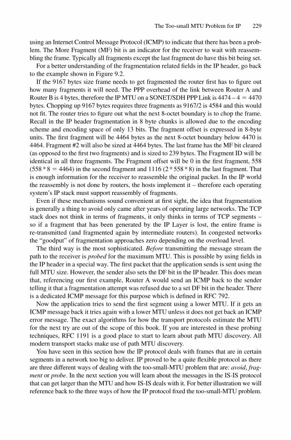
using an Internet Control Message Protocol (ICMP) to indicate that there has been a prob-lem. The More Fragment (MF) bit is an indicator for the receiver to wait with reassem-bling the frame. Typically all fragments except the last fragment do have this bit being set.
For a better understanding of the fragmentation related fields in the IP header, go backto the example shown in Figure 9.2.
If the 9167 bytes size frame needs to get fragmented the router first has to figure outhow many fragments it will need. The PPP overhead of the link between Router A andRouter B is 4 bytes, therefore the IP MTU on a SONET/SDH PPP Link is 4474 – 4 � 4470bytes. Chopping up 9167 bytes requires three fragments as 9167/2 is 4584 and this wouldnot fit. The router tries to figure out what the next 8-octet boundary is to chop the frame.Recall in the IP header fragmentation in 8 byte chunks is allowed due to the encodingscheme and encoding space of only 13 bits. The fragment offset is expressed in 8-byteunits. The first fragment will be 4464 bytes as the next 8-octet boundary below 4470 is4464. Fragment #2 will also be sized at 4464 bytes. The last frame has the MF bit cleared(as opposed to the first two fragments) and is sized to 239 bytes. The Fragment ID will beidentical in all three fragments. The Fragment offset will be 0 in the first fragment, 558(558 * 8 � 4464) in the second fragment and 1116 (2 * 558 * 8) in the last fragment. Thatis enough information for the receiver to reassemble the original packet. In the IP worldthe reassembly is not done by routers, the hosts implement it – therefore each operatingsystem’s IP stack must support reassembly of fragments.
Even if these mechanisms sound convenient at first sight, the idea that fragmentationis generally a thing to avoid only came after years of operating large networks. The TCPstack does not think in terms of fragments, it only thinks in terms of TCP segments –so if a fragment that has been generated by the IP Layer is lost, the entire frame is re-transmitted (and fragmented again by intermediate routers). In congested networksthe “goodput” of fragmentation approaches zero depending on the overload level.
The third way is the most sophisticated. Before transmitting the message stream thepath to the receiver is probed for the maximum MTU. This is possible by using fields inthe IP header in a special way. The first packet that the application sends is sent using thefull MTU size. However, the sender also sets the DF bit in the IP header. This does meanthat, referencing our first example, Router A would send an ICMP back to the sendertelling it that a fragmentation attempt was refused due to a set DF bit in the header. Thereis a dedicated ICMP message for this purpose which is defined in RFC 792.
Now the application tries to send the first segment using a lower MTU. If it gets anICMP message back it tries again with a lower MTU unless it does not get back an ICMPerror message. The exact algorithms for how the transport protocols estimate the MTUfor the next try are out of the scope of this book. If you are interested in these probingtechniques, RFC 1191 is a good place to start to learn about path MTU discovery. Allmodern transport stacks make use of path MTU discovery.
You have seen in this section how the IP protocol deals with frames that are in certainsegments in a network too big to deliver. IP proved to be a quite flexible protocol as thereare three different ways of dealing with the too-small-MTU problem that are: avoid, frag-ment or probe. In the next section you will learn about the messages in the IS-IS protocolthat can get larger than the MTU and how IS-IS deals with it. For better illustration we willreference back to the three ways of how the IP protocol fixed the too-small-MTU problem.
The Too-small MTU Problem for IP 229
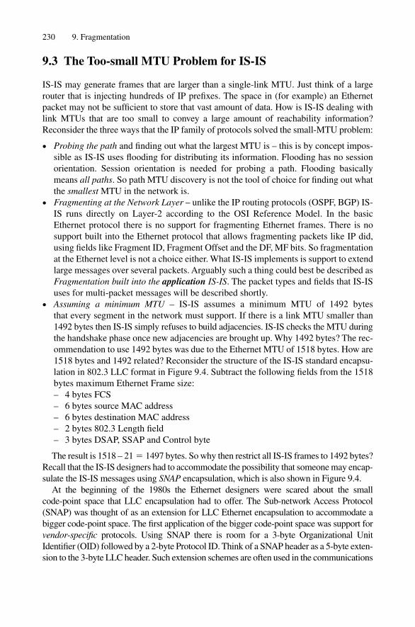
9.3 The Too-small MTU Problem for IS-IS
IS-IS may generate frames that are larger than a single-link MTU. Just think of a largerouter that is injecting hundreds of IP prefixes. The space in (for example) an Ethernetpacket may not be sufficient to store that vast amount of data. How is IS-IS dealing withlink MTUs that are too small to convey a large amount of reachability information?Reconsider the three ways that the IP family of protocols solved the small-MTU problem:
• Probing the path and finding out what the largest MTU is – this is by concept impos-sible as IS-IS uses flooding for distributing its information. Flooding has no sessionorientation. Session orientation is needed for probing a path. Flooding basicallymeans all paths. So path MTU discovery is not the tool of choice for finding out whatthe smallest MTU in the network is.
• Fragmenting at the Network Layer – unlike the IP routing protocols (OSPF, BGP) IS-IS runs directly on Layer-2 according to the OSI Reference Model. In the basicEthernet protocol there is no support for fragmenting Ethernet frames. There is nosupport built into the Ethernet protocol that allows fragmenting packets like IP did,using fields like Fragment ID, Fragment Offset and the DF, MF bits. So fragmentationat the Ethernet level is not a choice either. What IS-IS implements is support to extendlarge messages over several packets. Arguably such a thing could best be described asFragmentation built into the application IS-IS. The packet types and fields that IS-ISuses for multi-packet messages will be described shortly.
• Assuming a minimum MTU – IS-IS assumes a minimum MTU of 1492 bytes that every segment in the network must support. If there is a link MTU smaller than1492 bytes then IS-IS simply refuses to build adjacencies. IS-IS checks the MTU duringthe handshake phase once new adjacencies are brought up. Why 1492 bytes? The rec-ommendation to use 1492 bytes was due to the Ethernet MTU of 1518 bytes. How are1518 bytes and 1492 related? Reconsider the structure of the IS-IS standard encapsu-lation in 802.3 LLC format in Figure 9.4. Subtract the following fields from the 1518bytes maximum Ethernet Frame size:– 4 bytes FCS– 6 bytes source MAC address– 6 bytes destination MAC address– 2 bytes 802.3 Length field– 3 bytes DSAP, SSAP and Control byte
The result is 1518 – 21 � 1497 bytes. So why then restrict all IS-IS frames to 1492 bytes?Recall that the IS-IS designers had to accommodate the possibility that someone may encap-sulate the IS-IS messages using SNAP encapsulation, which is also shown in Figure 9.4.
At the beginning of the 1980s the Ethernet designers were scared about the small code-point space that LLC encapsulation had to offer. The Sub-network Access Protocol(SNAP) was thought of as an extension for LLC Ethernet encapsulation to accommodate abigger code-point space. The first application of the bigger code-point space was support forvendor-specific protocols. Using SNAP there is room for a 3-byte Organizational UnitIdentifier (OID) followed by a 2-byte Protocol ID. Think of a SNAP header as a 5-byte exten-sion to the 3-byte LLC header. Such extension schemes are often used in the communications
230 9. Fragmentation

Des
tinat
ion
MA
C A
ddre
ss01
80:c
200:
0014
or
018
0:c2
00:0
015
Byt
es 6 6 2 1 1 1
min
.:
27
max
.: Li
nk M
TU
-21
Sou
rce
MA
C A
ddre
ss
IEE
E 8
02.3
Len
gth
field
IEE
E 8
02.3
DS
AP
IEE
E 8
02.3
SS
AP
IEE
E 8
02.3
Con
trol
IS-I
S c
omm
on h
eade
r &
TLV
s
FC
S
0xF
E
0xF
E
0x03
4
Des
tinat
ion
MA
C A
ddre
ss01
80:c
200:
0014
or
018
0:c2
00:0
015
Byt
es 6 6 2 1 1 1
min
.:
27
max
.: Li
nk M
TU
-21
Sou
rce
MA
C A
ddre
ss
IEE
E 8
02.3
Len
gth
field
IEE
E 8
02.3
DS
AP
IEE
E 8
02.3
SS
AP
IEE
E 8
02.3
Con
trol
IS-I
S c
omm
on h
eade
r &
TLV
s
FC
S
0xA
A
0xA
A
0x03
4
SN
AP
hea
der
OU
I3
0
SN
AP
hea
der
PID
0x80
FE
2
802.
3S
NA
P E
ncap
sula
tion
802.
3L
LC
Enc
apsu
latio
n
FIG
UR
E9.
4. I
S-IS
for
mal
ly s
peci
fied
enca
psul
atio
n ov
er 8
02.3
LL
C a
nd 8
02.3
SN
AP
Lay
er-2
enc
apsu
latio
n; h
owev
er,a
ll im
plem
enta
tions
toda
y us
e80
2.3
LL
C e
ncap
sula
tion
231

industry. Most protocols have a special code-point reserved for further extension. In the LLCprotocol, it is 0xAA that indicates that there is a 5-byte SNAP header to parse.
This is where the 5-byte difference between 1497 and 1492 comes from. The ironicthing here is that although absolutely no vendor ever implemented IS-IS over SNAPencapsulation, all implementations honour the 1492 bytes size of this “would-be-SNAP-encapsulated” boundary. Virtually all IS-IS implementations support just the LLC encap-sulation, which leaves room for 1497 bytes for an IS-IS frame over standard Ethernettechnology.
Figure 9.5 shows the output of a real-word IS-IS frame decoded by Ethereal, a public-domain protocol analyzer (http://www.ethereal.com).
Frequently students in classes notice that a router sends out the first set of Hellos up tothe maximum size of an Ethernet frame to detect the MTU of the link, that the length ofthe IS-IS frame is 1497 bytes. You can check that out using the following debug andmonitoring commands.
Tcpdump/JUNOS command outputhannes@London> monitor traffic Interface fe-0/0/0
00:01:36.850702 OSI, IS-IS, length: 1497
L1 Lan IIH, hlen: 27, v: 1, pdu-v: 1, sys-id-len: 6 (0), max-area: 3 (0)
source-id: 0000.0000.0002, holding time: 13s, Flags: [Level 1, Level 2]
lan-id: 0000.0000.0002.02, Priority: 64, PDU length: 1497
IS Neighbor(s) TLV #6, length: 6
IS Neighbor: 0002.b32b.0e52
Protocols supported TLV #129, length: 1
NLPID(s): IPv4
IPv4 Interface address(es) TLV #132, length: 4
IPv4 interface address: 193.83.223.236
Area address(es) TLV #1, length: 4
Area address (3): 49.0001
Padding TLV #8, length: 255
Padding TLV #8, length: 255
Padding TLV #8, length: 255
Padding TLV #8, length: 255
Padding TLV #8, length: 255
Padding TLV #8, length: 160
On a router running IOS you can find out how big the packets that the router sends outare by using the debug isis adj-packets command.
IOS command outputLondon#debug isis adj-packets
IS-IS Adjacency related packets debugging is on
Jun 9 20:25:14.319 UTC: ISIS-Adj: Sending L2 LAN IIH on Ethernet0, length 1497
Jun 9 20:25:14.575 UTC: ISIS-Adj: Rec L2 IIH from 00d0.ba58.7e4b (Ethernet0), cir
type L2, cir id 0010.0100.1005.03, length 1497
232 9. Fragmentation

FIG
UR
E9.
5. A
n IS
-IS
Fram
e re
cord
ed b
y E
ther
eal,
a pu
blic
dom
ain
Prot
ocol
Ana
lyze
r
233

It has already been mentioned that the official MTU that each circuit must support is1492, as defined in the IS-IS base specification ISO 10589. However, as all vendors onlyimplement LLC encapsulation, the unofficial MTU (don’t quote us on that) that each IS-IS may use is 1497 bytes.
The next section takes a closer look to the term application level fragmentation andwhat it means. All the different IS-IS packets and how they are prepared for multi-packetmessaging will be discussed.
9.4 IS-IS Application Level Fragmentation
IS-IS uses three different packet types for various purposes:
1. Hellos (IIHs) for neighbour discovery and MTU check2. Sequence number packets (SNPs) for synchronization and reliable updates3. Link-state packets (LSPs) for conveying reachability information
9.4.1 Hellos (IIHs)The Intermediate System to Intermediate System Hello PDU, or IIH, is used for neigh-bour and MTU discovery. The purpose of neighbour discovery was explained in Chapter5, “Neighbour Discovery and Handshaking”. There is also an MTU check that verifies ifboth ends of an IS-IS adjacency comply with the minimum MTU of 1492 bytes. IS-ISachieves that check by using a technique called padding. Using padding, the Hello mes-sage is artificially pumped up to the MTU size of the link, or 1492 bytes. Whether theupdate gets pumped up to just 1492 bytes or the full MTU size is a decision that is solelydependent on the implementation of the IS-IS protocol. For instance, JUNOS only padsup to 1492 bytes but IOS always tries to pad to the maximum MTU size. A typical IIH(Hello message) is between 40–70 bytes these days. The size of the Hello message mayvary as all new capabilities are added to the base IS-IS protocol are indicated in the Hellomessage, and it therefore gets bigger through the years as capabilities are added to IS-IS.There has been a trend in the past that the IS-IS Hello message gets bigger on average by5 bytes each year. Ultimately, this is not an issue as there is quite a lot of headroom togrow until the max IIH packet size of (worst-case) 1497 bytes is reached. Some imple-mentations like IOS can even utilize the full-link MTU for Hellos, which is nice becauseit postpones worries like these even more. Changing the Hello size is a purely link-localdecision and as long as both parties do not complain about the large Hellos, everythingwill be fine and the adjacency goes into Up state.
However, even when an IS-IS Hello is 70 bytes in size, it is still far off the minimumMTU size of 1492 bytes that every IS-IS circuit has to support. How does IS-IS pad from70 bytes of content to 1492 bytes? There is a special Padding TLV that helps to add nonsense data in a structured way just to make the frame bigger. In Figure 9.6 you cansee the structure of the Padding TLV.
There is more about TLV encoding in Chapter 11 “TLVs and Sub-TLVs”. The PaddingTLV may contain an arbitrary set of data. The Padding TLV can also occur several times
234 9. Fragmentation

in the Hello message. Actually, it has to occur several times in the Hello because a singlePadding TLV can only hold, and therefore pad, up to 255 bytes. So there may be up tofive full-sized Padding TLVs necessary to make the frame big enough. The followingtcpdump output shows several occurrences of the Padding TLV #8.
Tcpdump output00:58:53.561521 OSI, IS-IS, length: 1497
L1 Lan IIH, hlen: 27, v: 1, pdu-v: 1, sys-id-len: 6 (0), max-area: 3 (0)
Point-to-point Adjacency State TLV #240, length: 1
Adjacency State: Up
Protocols supported TLV #129, length: 2
NLPID(s): IPv4, IPv6
IPv4 Interface address(es) TLV #132, length: 4
IPv4 interface address: 193.83.223.237
Area address(es) TLV #1, length: 4
Area address (3): 49.0001
Restart Signaling TLV #211, length: 3
Restart Request bit clear, Restart Acknowledgement bit clear
Remaining holding time: 0s
Checksum TLV #12, length: 2
checksum: 0xadbb (correct)
IS-IS Application Level Fragmentation 235
TLV Type
TLV Length
Remaining Lifetime
9
Bytes
1
1
ID Length (6) +2
2
4
2
LSP-ID
Sequence Number
Checksum
N * 16
Remaining Lifetime
ID Length (6) +2
2
4
2
LSP-ID
Sequence Number
Checksum
FIGURE 9.6.

Padding TLV #8, length: 255
Padding TLV #8, length: 255
Padding TLV #8, length: 255
Padding TLV #8, length: 255
Padding TLV #8, length: 255
Padding TLV #8, length: 168
There is no mechanism in the Hello protocol to support more information than fits in asingle packet. There is no concept of distributing (for instance) certain capability codes overseveral Hello messages. In IS-IS each preceding Hello message entirely supersedes the pre-vious one. There is simply no support for multi-part Hello messages. That gives also theupper boundary of 1492 bytes that each neighbour may advertise. Luckily, IS-IS today uti-lizes only 5 per cent of that space. In Hello messages there is no need to support multi-packetmessages and therefore in the application IS-IS there is no hook for multi-part Hello mes-sages specified.
9.4.2 Sequence Number Packets (SNPs)Sequence Number Packets (SNPs) have two flavours, complete (CSNP) and partial(PSNP), and three purposes:
1. Acknowledging receipt of a link-state packet (a job for PSNP)2. Requesting a more recent version of LSPs due to detection of a mismatch of some
LSPs in the link-state database (also PSNP)3. Publishing all the headers of the link-state database (this is for CSNP)
There is more information about the details of synchronizing link-state databases andthe use of CSNPs and PSNPs in Chapter 8. All you have to know is that IS-IS reports ele-ments from the link-state database using a special envelope called the LSP Entry TLV #9.In Figure 9.7 you can see the structure of TLV #9. In the above-mentioned three uses ofSNPs, all transport one, many or all LSP headers that the link-state database holds.
For an acknowledgement, typically only one occurrence of the LSP Entry TLV #9 is needed. The following tcpdump output shows you a PSNP that serves as an acknowledgement.
Tcpdump output01:30:05.788280 OSI, IS-IS, length: 44
L2 PSNP, hlen: 17, v: 1, pdu-v: 1, sys-id-len: 6 (0), max-area: 3 (0)
source-id: 6b01.c219.07fa.00
LSP entries TLV #9, length: 16
lsp-id: 011c.9a4f.0d02.00-00, seq: 0x000014f4, lifetime:
65522s, chksum: 0xb1cf
Authentication TLV #10, length: 8
simple text password: Juniper
236 9. Fragmentation

This PSNP message was generated in response to an LSP with the LSP-ID of011c.9a4f.0d02.00-00. There is just one occurrence of TLV #9 and it holds justone entry. Finally, it is properly authenticated.
However, an implementation may decide to wait for a certain amount of time and thenbundle a few acknowledgements together. There can be more than one LSP-ID in aPSNP frame mentioned using the LSP Entry TLV #9. What if all the acknowledged LSP-IDs in a PSNP frame do not fit into a single packet? No problem – as the atomic elementin the PSNP is the LSP Entry field itself. In other words: All the LSP Entries are totallyunrelated to each other. The particular order of an LSP-Entry TLV in a PSNP is totallymeaningless. Unlike Hello messages where there are many different TLVs in a Hellomessage the entire Hello message is the atomic element – some TLVs are related to eachother and therefore must occur in the same packet.
In the PSNP there is not much that may be related – there is only the LSP Entry TLVs(plus the authentication and checksum TLV) and it is not related to any other TLV. Thatis the reason why IS-IS may spread a large amount of acknowledgements over severalpackets – they are not related to each other.
The second application for PSNPs is requesting a more recent version of LSPs. Duringthe adjacency formation phase an IS-IS router may detect that the other router holds newerversions of certain LSP Entries in the link-state database. By explicitly enumerating theLSP Entries that the router is interested in it is requesting a retransmission of the LSPs inquestion. The tcpdump shows a request of more recent LSPs.
IS-IS Application Level Fragmentation 237
TLV Type
TLV Length
Remaining Lifetime
9
Bytes
1
1
ID Length (6) � 2
2
4
2
LSP-ID
Sequence Number
Checksum
N * 16
Remaining Lifetime
ID Length (6) � 2
2
4
2
LSP-ID
Sequence Number
Checksum
FIGURE 9.7. The LSP Entry TLV #9
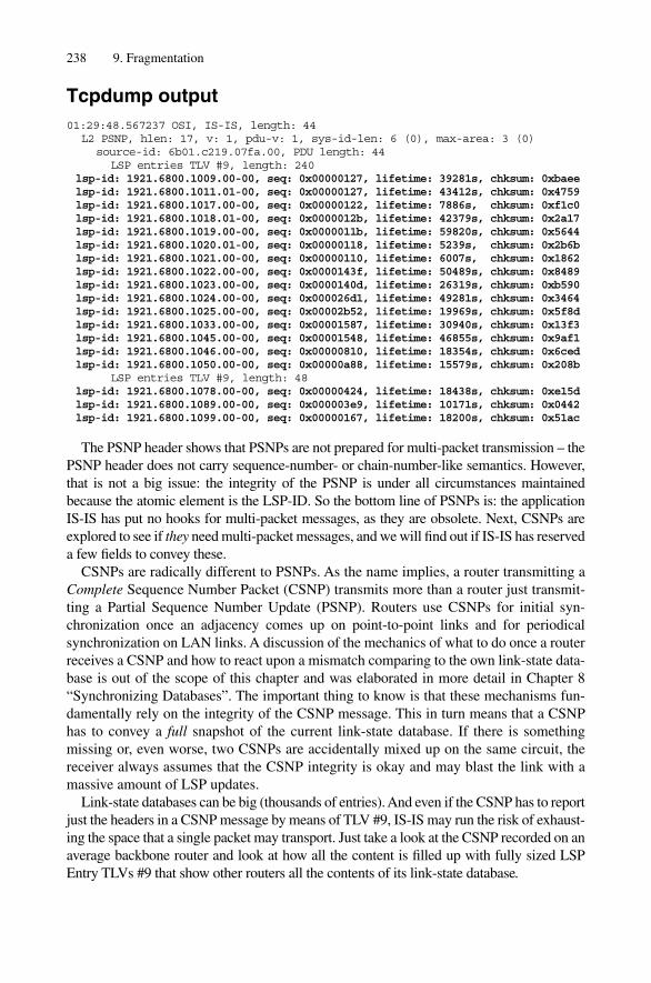
Tcpdump output01:29:48.567237 OSI, IS-IS, length: 44
L2 PSNP, hlen: 17, v: 1, pdu-v: 1, sys-id-len: 6 (0), max-area: 3 (0)source-id: 6b01.c219.07fa.00, PDU length: 44
LSP entries TLV #9, length: 240lsp-id: 1921.6800.1009.00-00, seq: 0x00000127, lifetime: 39281s, chksum: 0xbaeelsp-id: 1921.6800.1011.01-00, seq: 0x00000127, lifetime: 43412s, chksum: 0x4759lsp-id: 1921.6800.1017.00-00, seq: 0x00000122, lifetime: 7886s, chksum: 0xf1c0lsp-id: 1921.6800.1018.01-00, seq: 0x0000012b, lifetime: 42379s, chksum: 0x2a17lsp-id: 1921.6800.1019.00-00, seq: 0x0000011b, lifetime: 59820s, chksum: 0x5644lsp-id: 1921.6800.1020.01-00, seq: 0x00000118, lifetime: 5239s, chksum: 0x2b6blsp-id: 1921.6800.1021.00-00, seq: 0x00000110, lifetime: 6007s, chksum: 0x1862lsp-id: 1921.6800.1022.00-00, seq: 0x0000143f, lifetime: 50489s, chksum: 0x8489lsp-id: 1921.6800.1023.00-00, seq: 0x0000140d, lifetime: 26319s, chksum: 0xb590lsp-id: 1921.6800.1024.00-00, seq: 0x000026d1, lifetime: 49281s, chksum: 0x3464lsp-id: 1921.6800.1025.00-00, seq: 0x00002b52, lifetime: 19969s, chksum: 0x5f8dlsp-id: 1921.6800.1033.00-00, seq: 0x00001587, lifetime: 30940s, chksum: 0x13f3lsp-id: 1921.6800.1045.00-00, seq: 0x00001548, lifetime: 46855s, chksum: 0x9af1lsp-id: 1921.6800.1046.00-00, seq: 0x00000810, lifetime: 18354s, chksum: 0x6cedlsp-id: 1921.6800.1050.00-00, seq: 0x00000a88, lifetime: 15579s, chksum: 0x208b
LSP entries TLV #9, length: 48lsp-id: 1921.6800.1078.00-00, seq: 0x00000424, lifetime: 18438s, chksum: 0xe15dlsp-id: 1921.6800.1089.00-00, seq: 0x000003e9, lifetime: 10171s, chksum: 0x0442lsp-id: 1921.6800.1099.00-00, seq: 0x00000167, lifetime: 18200s, chksum: 0x51ac
The PSNP header shows that PSNPs are not prepared for multi-packet transmission – thePSNP header does not carry sequence-number- or chain-number-like semantics. However,that is not a big issue: the integrity of the PSNP is under all circumstances maintainedbecause the atomic element is the LSP-ID. So the bottom line of PSNPs is: the applicationIS-IS has put no hooks for multi-packet messages, as they are obsolete. Next, CSNPs areexplored to see if they need multi-packet messages, and we will find out if IS-IS has reserveda few fields to convey these.
CSNPs are radically different to PSNPs. As the name implies, a router transmitting aComplete Sequence Number Packet (CSNP) transmits more than a router just transmit-ting a Partial Sequence Number Update (PSNP). Routers use CSNPs for initial syn-chronization once an adjacency comes up on point-to-point links and for periodicalsynchronization on LAN links. A discussion of the mechanics of what to do once a routerreceives a CSNP and how to react upon a mismatch comparing to the own link-state data-base is out of the scope of this chapter and was elaborated in more detail in Chapter 8“Synchronizing Databases”. The important thing to know is that these mechanisms fun-damentally rely on the integrity of the CSNP message. This in turn means that a CSNPhas to convey a full snapshot of the current link-state database. If there is somethingmissing or, even worse, two CSNPs are accidentally mixed up on the same circuit, thereceiver always assumes that the CSNP integrity is okay and may blast the link with amassive amount of LSP updates.
Link-state databases can be big (thousands of entries). And even if the CSNP has to reportjust the headers in a CSNP message by means of TLV #9, IS-IS may run the risk of exhaust-ing the space that a single packet may transport. Just take a look at the CSNP recorded on anaverage backbone router and look at how all the content is filled up with fully sized LSPEntry TLVs #9 that show other routers all the contents of its link-state database.
238 9. Fragmentation

Tcpdump output01:29:48.567237 OSI, IS-IS, length: 1478
L2 CSNP, hlen: 33, v: 1, pdu-v: 1, sys-id-len: 6 (0), max-area: 3 (0)source-id: 6b01.c219.07fa.00, PDU length: 1478start lsp-id: 1921.6800.1001.00-00end lsp-id: 1921.6802.0022.00-00
LSP entries TLV #9, length: 240lsp-id: 1921.6800.1001.01-00, seq: 0x000003ac, lifetime: 15110s, chksum: 0xd551lsp-id: 1921.6800.1001.02-00, seq: 0x0000011c, lifetime: 17576s, chksum: 0x47a0lsp-id: 1921.6800.1001.03-00, seq: 0x00000166, lifetime: 21751s, chksum: 0x96c8lsp-id: 1921.6800.0011.00-00, seq: 0x000000b9, lifetime: 27108s, chksum: 0xb43d[ … ]lsp-id: 1921.6801.0046.00-00, seq: 0x000006c7, lifetime: 47027s, chksum: 0x2c71lsp-id: 1921.6801.0057.00-00, seq: 0x000003cc, lifetime: 39228s, chksum: 0xa5c3lsp-id: 1921.6801.0063.00-00, seq: 0x000003ac, lifetime: 45114s, chksum: 0x4d09lsp-id: 1921.6801.0074.00-00, seq: 0x00000393, lifetime: 64927s, chksum: 0x048d
LSP entries TLV #9, length: 240lsp-id: 1921.6801.0074.00-00, seq: 0x00000453, lifetime: 21053s, chksum: 0xcc1alsp-id: 1921.6801.0074.02-00, seq: 0x000002fc, lifetime: 14740s, chksum: 0x67belsp-id: 1921.6801.0074.03-00, seq: 0x000002d5, lifetime: 5065s, chksum: 0x97a2lsp-id: 1921.6801.0088.00-00, seq: 0x0000033e, lifetime: 59876s, chksum: 0xd3cc[ … ]lsp-id: 1921.6802.0012.03-00, seq: 0x000000dc, lifetime: 43654s, chksum: 0xfc64lsp-id: 1921.6802.0018.00-00, seq: 0x00000530, lifetime: 56270s, chksum: 0x8b39lsp-id: 1921.6802.0018.00-00, seq: 0x00000494, lifetime: 14156s, chksum: 0xdd6a
LSP entries TLV #9, length: 240lsp-id: 1921.6802.0019.00-00, seq: 0x0000041f, lifetime: 59421s, chksum: 0x985dlsp-id: 1921.6802.0019.02-00, seq: 0x000000d3, lifetime: 54186s, chksum: 0xde3alsp-id: 1921.6802.0019.03-00, seq: 0x000000d4, lifetime: 44940s, chksum: 0xf814lsp-id: 1921.6802.0022.00-00, seq: 0x000019a1, lifetime: 12688s, chksum: 0x26f9[ … ]
A single packet cannot hold up all the LSP headers of a fully blown link-state databaseof the sizes in the Internet today. However, if you take a look at the tcpdump above youmay find, contrary to PSNPs, some mechanisms in the header that support multi-packetmessages. Those are the Start-LSP and End-LSP fields in the CSNP header. CSNPs areprepared from day one to fully support multi-packet messages. Therefore it needs amarker to find out when the synchronization process is over and when the receivingrouter can start to compute the difference to its local link-state database and either floodor request more recent instances of a LSP. The Start-LSP-ID and End-LSP-ID fields helpto indicate when a synchronization process is over. The Start-LSP-ID field of the firstmessage in a multi-message CSNP is set to 0000.0000.0000.00-00 and the End-LSP-IDfield is set to FFFF.FFFF.FFFF.FF-FF. If your environment is a very small one (like oursample topology) the full CSNP fits into a single packet and most probably looks like thefollowing.
Tcpdump output00:33:02.536076 OSI, IS-IS, length: 99
L2 CSNP, hlen: 33, v: 1, pdu-v: 1, sys-id-len: 6 (0), max-area: 3 (0)source-id: 0000.0000.0002.00, PDU length: 99start lsp-id: 0000.0000.0000.00-00end lsp-id: ffff.ffff.ffff.ff-ff
IS-IS Application Level Fragmentation 239
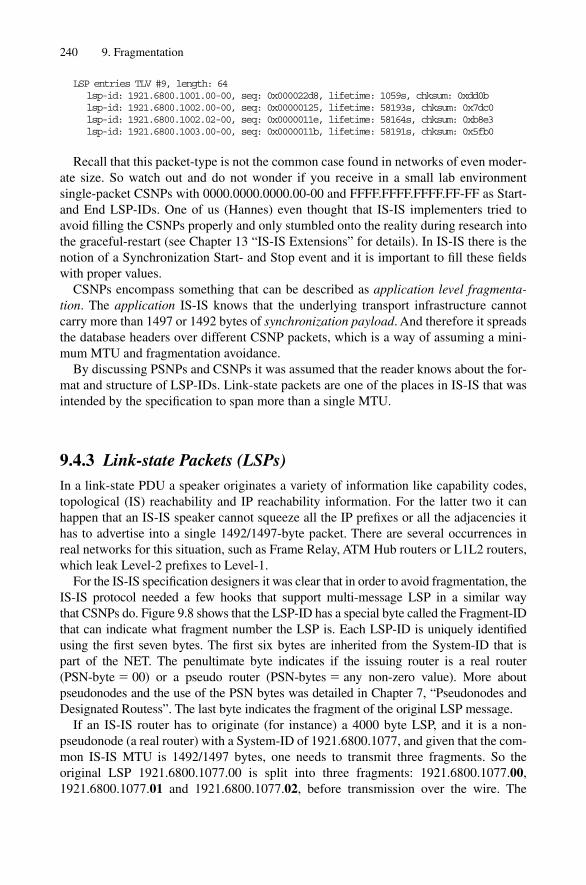
LSP entries TLV #9, length: 64lsp-id: 1921.6800.1001.00-00, seq: 0x000022d8, lifetime: 1059s, chksum: 0xdd0blsp-id: 1921.6800.1002.00-00, seq: 0x00000125, lifetime: 58193s, chksum: 0x7dc0lsp-id: 1921.6800.1002.02-00, seq: 0x0000011e, lifetime: 58164s, chksum: 0xb8e3lsp-id: 1921.6800.1003.00-00, seq: 0x0000011b, lifetime: 58191s, chksum: 0x5fb0
Recall that this packet-type is not the common case found in networks of even moder-ate size. So watch out and do not wonder if you receive in a small lab environment single-packet CSNPs with 0000.0000.0000.00-00 and FFFF.FFFF.FFFF.FF-FF as Start-and End LSP-IDs. One of us (Hannes) even thought that IS-IS implementers tried toavoid filling the CSNPs properly and only stumbled onto the reality during research intothe graceful-restart (see Chapter 13 “IS-IS Extensions” for details). In IS-IS there is thenotion of a Synchronization Start- and Stop event and it is important to fill these fieldswith proper values.
CSNPs encompass something that can be described as application level fragmenta-tion. The application IS-IS knows that the underlying transport infrastructure cannotcarry more than 1497 or 1492 bytes of synchronization payload. And therefore it spreadsthe database headers over different CSNP packets, which is a way of assuming a mini-mum MTU and fragmentation avoidance.
By discussing PSNPs and CSNPs it was assumed that the reader knows about the for-mat and structure of LSP-IDs. Link-state packets are one of the places in IS-IS that wasintended by the specification to span more than a single MTU.
9.4.3 Link-state Packets (LSPs)In a link-state PDU a speaker originates a variety of information like capability codes,topological (IS) reachability and IP reachability information. For the latter two it canhappen that an IS-IS speaker cannot squeeze all the IP prefixes or all the adjacencies ithas to advertise into a single 1492/1497-byte packet. There are several occurrences inreal networks for this situation, such as Frame Relay, ATM Hub routers or L1L2 routers,which leak Level-2 prefixes to Level-1.
For the IS-IS specification designers it was clear that in order to avoid fragmentation, theIS-IS protocol needed a few hooks that support multi-message LSP in a similar way that CSNPs do. Figure 9.8 shows that the LSP-ID has a special byte called the Fragment-IDthat can indicate what fragment number the LSP is. Each LSP-ID is uniquely identifiedusing the first seven bytes. The first six bytes are inherited from the System-ID that is part of the NET. The penultimate byte indicates if the issuing router is a real router (PSN-byte � 00) or a pseudo router (PSN-bytes � any non-zero value). More aboutpseudonodes and the use of the PSN bytes was detailed in Chapter 7, “Pseudonodes andDesignated Routess”. The last byte indicates the fragment of the original LSP message.
If an IS-IS router has to originate (for instance) a 4000 byte LSP, and it is a non-pseudonode (a real router) with a System-ID of 1921.6800.1077, and given that the com-mon IS-IS MTU is 1492/1497 bytes, one needs to transmit three fragments. So theoriginal LSP 1921.6800.1077.00 is split into three fragments: 1921.6800.1077.00,1921.6800.1077.01 and 1921.6800.1077.02, before transmission over the wire. The
240 9. Fragmentation

receiving router simply installs all three fragments in the link-state database and IS-ISembedded synchronization mechanisms (CSNPs and PSNPs) make sure that all the frag-ments are known to all the routers in a network. Of course, everything that can go wrongwith LSPs will go wrong in practice. IS-IS is very liberal in that respect. It does not careif all the fragments finally arrive at the receiver or delay an SPF calculation for route cal-culation because of a missing fragment. The embedded CSNP and PSNP mechanismsare considered to be robust enough to make sure that ultimately all LSPs get delivered.There is one exception to this rule: handling of Fragment zero has a few rules that everyIS-IS speaker has to obey.
9.4.3.1 Fragment Zero
IS-IS does not care if any non-zero fragment is lost – nothing gets delayed or declaredbogus because of that. Fragment zero, however, has some rules and restrictions.
First of all, if Fragment zero is not present, then the entire set of fragments will bedeclared invalid, as there is some mandatory information in Fragment zero that is vital,for example, to SPF computation. There are further restrictions such as: if it is not inFragment zero, it must also not be contained anywhere else. And if Fragment zero ismissing, then the SPF computation cannot start to process the link-state database. Themost important information that needs to be present in SPF runs is:
1. The union of all L1 Areas encoded in the Area TLV #12. If Multi-Topologies extensions are enabled (see Chapter 13 “IS-IS Extensions”), the
Multi-Topologies Supported TLV #229
Those two LSPs contain information that are vital to SPF processing (most importantare the Overload and ATTach bits) if the state of information in Fragment zero is notknown it becomes irrelevant to process an SPF operation. Fragment zero is the centraldogma of IS-IS, everybody has to comply with the rules and properly advertise the AreaTLV #1 and Multi-Topology Supported TLV #229, otherwise the entire LSP’s non-zerofragments will be disregarded and thereby purged off the forwarding topology. On theother hand, those two TLVs are considered to be illegal in any non-zero fragment and areat best ignored. This behaviour comes from Jon Postel’s famous rule about protocolinteroperability: “Be tolerant what you receive and strict in what you send”. Both IOSand JUNOS follow this rule and only evaluate these two TLVs in Fragment zero.
IS-IS Application Level Fragmentation 241
1921.6820.4003.02-00System-ID Pseudonode-
IDFragment-
ID
FIGURE 9.8. The application IS-IS has dedicated one byte in its LSP-ID format to include packetfragment numbers

9.4.3.2 Fragment “Wander” Problems
The atomic element for a trigger that leads to an SPF calculation is a change in an LSP’s fragment. For example, if an adjacency is present in LSP-ID 1921.6800.1077.00-01 and it is not present in an updated LSP 1921.6800.1077.00-01, then an SPF calcula-tion is scheduled as the trigger condition is met. However, an IS-IS LSP is a linear streamof data and a change in size of a stream element (TLV) may need to organize the entirestream, as all the fragments need to be rebuilt. This problem is described as fragment“wander” and today modern IS-IS implementations have come up with “clue” logic toprevent that.
Naive IS-IS implementations build up a stream of TLV-encoded information and breakit apart afterwards for transmission on the circuits that have MTUs of 1492/1497 bytes.The word “naive” is used here because, although it does fulfil what is in the specification,it can create a lot amount of churn in the network by doing more than is mentioned in thespecification.
Consider Figure 9.9 for a better illustration of fragmentation as a way of post-pro-cessing a TLV stream. An IS-IS router generates a set of TLV-encoded informationincluding IS or IP Reachability TLVs. Now one adjacency goes down. A naive imple-mentation builds the entire stream from scratch and chops everything into pieces after-wards. What happens is that even adjacencies that have been stable like Adjacency #27are squeezed back into Fragment zero. That means that two fragments have to be rebuilt:Fragment zero and Fragment 1.
A “cluey” implementation builds the stream and fragments it first hand. When it has to re-originate one of its fragments, this approach tries to be as conservative as possible to save thenetwork portions that do not necessarily involve a change of link-state updates. Remember,
242 9. Fragmentation
Area Adj #1 Adj #2 Adj #3 Adj #27 Adj #28
Fragment 00, 1492 bytes Fragment 01120 bytes
Area Adj #1 Adj #3 Adj #28
Fragment 00, 1492 bytes Frag. 0170 bytes
Adj #4Naive implementation
Cluey implementation Adj #27 Adj #28
Fragment 01120 bytes
Area Adj #1 Adj #3
Fragment 00, 1492 bytes
Adj #4
FIGURE 9.9. Naive implementation can generate a lot of churn in the network by blindly re-buildingevery fragment on every change in adjacencies or IP reachability.
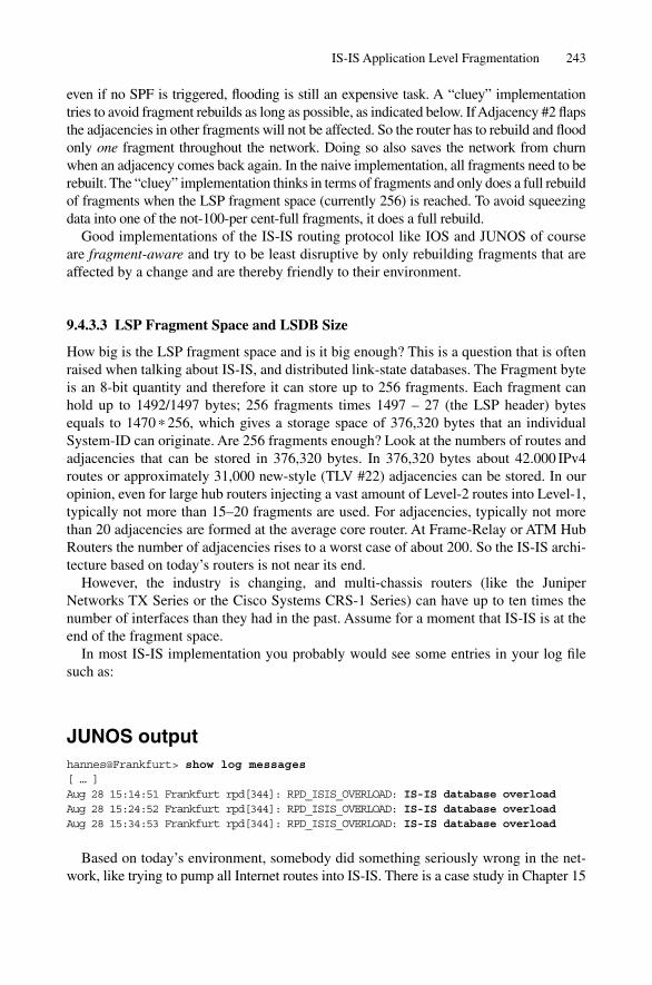
even if no SPF is triggered, flooding is still an expensive task. A “cluey” implementationtries to avoid fragment rebuilds as long as possible, as indicated below. If Adjacency #2 flapsthe adjacencies in other fragments will not be affected. So the router has to rebuild and floodonly one fragment throughout the network. Doing so also saves the network from churnwhen an adjacency comes back again. In the naive implementation, all fragments need to berebuilt. The “cluey” implementation thinks in terms of fragments and only does a full rebuildof fragments when the LSP fragment space (currently 256) is reached. To avoid squeezingdata into one of the not-100-per cent-full fragments, it does a full rebuild.
Good implementations of the IS-IS routing protocol like IOS and JUNOS of courseare fragment-aware and try to be least disruptive by only rebuilding fragments that areaffected by a change and are thereby friendly to their environment.
9.4.3.3 LSP Fragment Space and LSDB Size
How big is the LSP fragment space and is it big enough? This is a question that is oftenraised when talking about IS-IS, and distributed link-state databases. The Fragment byteis an 8-bit quantity and therefore it can store up to 256 fragments. Each fragment canhold up to 1492/1497 bytes; 256 fragments times 1497 – 27 (the LSP header) bytesequals to 1470 * 256, which gives a storage space of 376,320 bytes that an individualSystem-ID can originate. Are 256 fragments enough? Look at the numbers of routes andadjacencies that can be stored in 376,320 bytes. In 376,320 bytes about 42.000 IPv4routes or approximately 31,000 new-style (TLV #22) adjacencies can be stored. In ouropinion, even for large hub routers injecting a vast amount of Level-2 routes into Level-1,typically not more than 15–20 fragments are used. For adjacencies, typically not morethan 20 adjacencies are formed at the average core router. At Frame-Relay or ATM HubRouters the number of adjacencies rises to a worst case of about 200. So the IS-IS archi-tecture based on today’s routers is not near its end.
However, the industry is changing, and multi-chassis routers (like the JuniperNetworks TX Series or the Cisco Systems CRS-1 Series) can have up to ten times thenumber of interfaces than they had in the past. Assume for a moment that IS-IS is at theend of the fragment space.
In most IS-IS implementation you probably would see some entries in your log filesuch as:
JUNOS outputhannes@Frankfurt> show log messages[ … ]Aug 28 15:14:51 Frankfurt rpd[344]: RPD_ISIS_OVERLOAD: IS-IS database overloadAug 28 15:24:52 Frankfurt rpd[344]: RPD_ISIS_OVERLOAD: IS-IS database overloadAug 28 15:34:53 Frankfurt rpd[344]: RPD_ISIS_OVERLOAD: IS-IS database overload
Based on today’s environment, somebody did something seriously wrong in the net-work, like trying to pump all Internet routes into IS-IS. There is a case study in Chapter 15
IS-IS Application Level Fragmentation 243
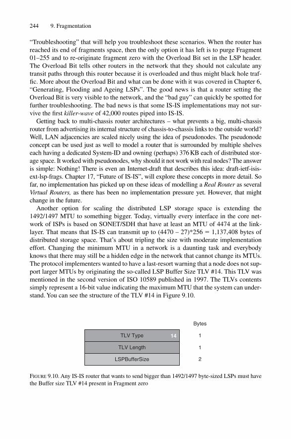
“Troubleshooting” that will help you troubleshoot these scenarios. When the router hasreached its end of fragments space, then the only option it has left is to purge Fragment01–255 and to re-originate fragment zero with the Overload Bit set in the LSP header.The Overload Bit tells other routers in the network that they should not calculate anytransit paths through this router because it is overloaded and thus might black hole traf-fic. More about the Overload Bit and what can be done with it was covered in Chapter 6,“Generating, Flooding and Ageing LSPs”. The good news is that a router setting theOverload Bit is very visible to the network, and the “bad guy” can quickly be spotted forfurther troubleshooting. The bad news is that some IS-IS implementations may not sur-vive the first killer-wave of 42,000 routes piped into IS-IS.
Getting back to multi-chassis router architectures – what prevents a big, multi-chassisrouter from advertising its internal structure of chassis-to-chassis links to the outside world?Well, LAN adjacencies are scaled nicely using the idea of pseudonodes. The pseudonodeconcept can be used just as well to model a router that is surrounded by multiple shelveseach having a dedicated System-ID and owning (perhaps) 376 KB each of distributed stor-age space. It worked with pseudonodes, why should it not work with real nodes? The answeris simple: Nothing! There is even an Internet-draft that describes this idea: draft-ietf-isis-ext-lsp-frags. Chapter 17, “Future of IS-IS”, will explore these concepts in more detail. Sofar, no implementation has picked up on these ideas of modelling a Real Router as severalVirtual Routers, as there has been no implementation pressure yet. However, that mightchange in the future.
Another option for scaling the distributed LSP storage space is extending the1492/1497 MTU to something bigger. Today, virtually every interface in the core net-work of ISPs is based on SONET/SDH that have at least an MTU of 4474 at the link-layer. That means that IS-IS can transmit up to (4470 – 27)*256 � 1,137,408 bytes ofdistributed storage space. That’s about tripling the size with moderate implementationeffort. Changing the minimum MTU in a network is a daunting task and everybodyknows that there may still be a hidden edge in the network that cannot change its MTUs.The protocol implementers wanted to have a last-resort warning that a node does not sup-port larger MTUs by originating the so-called LSP Buffer Size TLV #14. This TLV wasmentioned in the second version of ISO 10589 published in 1997. The TLVs contentssimply represent a 16-bit value indicating the maximum MTU that the system can under-stand. You can see the structure of the TLV #14 in Figure 9.10.
244 9. Fragmentation
TLV Type
TLV Length
LSPBufferSize
14
Bytes
1
1
2
FIGURE 9.10. Any IS-IS router that wants to send bigger than 1492/1497 byte-sized LSPs must havethe Buffer size TLV #14 present in Fragment zero

9.5 Summary
Contrary to IP routing protocols, IS-IS cannot rely on a network layer to do fragmentationfor it. IS-IS runs directly on the link-layer, which has no possibility of fragmenting frames.IS-IS therefore needs to apply a few techniques to get around the too-small MTU problemif it has to transmit a message that is larger than the MTU. The two techniques IS-IS usesfall under the category of fragmentation avoidance and application level fragmentation. IS-IS assumes a minimum MTU that every link has to support. This limit today is theoreti-cally 1492 and in practice 1497 bytes. Additionally in several packet types in IS-IS thereis support for multi-packet messages like CSNPs and LSPs. There are also details of howthe application IS-IS should fragment in order to avoid network-wide churn. “Cluey”implementations think in terms of fragments and try only to rebuild fragments that havebeen affected by an adjacency change. In current network architectures, the distributedLSP storage space is typically only utilized at 10 per cent, and even if the space couldbecome exhausted, the IS-IS working group has come up with a solution that is similar tomodelling adjacencies on a large LAN. There is also the possibility of raising the 1492byte limit of LSP buffer size as all modern interface cards, especially in core environ-ments, support MTUs up to 4474 bytes. Although not needed today, these developmentsare a good proof that the IS-IS infrastructure will exist for a long time to come in networks.
IS-IS Application Level Fragmentation 245

8
Synchronizing Databases
Link-state protocols rely fundamentally on the fact that each router in a given area hasthe same view of the topology. Sharing the same view is the foundation for computingconverged routes. Convergence means that each router computes routes in a way that movespackets one hop closer to the destination. If routes are not convergent, packets can takeextra hops in the network to reach the final destination. The worst case for misalignedroutes is a forwarding loop where packets are bounced back and forth between a pair ofrouters. In a changing network it is therefore paramount to get to a synchronized view of the topology as quickly as possible. New routers connected to the network need toquery their neighbour’s link-state databases to get on the same page as quickly as pos-sible. This chapter discusses the IS-IS mechanisms to initially synchronize link-statedatabases between routers and periodically update the databases.
This chapter starts with a detailed discussion of the consequences of link-state data-base misalignments. It continues with a detailed explanation of database synchronizationon point-to-point and broadcast links. Finally, refinements to ISO 10589 for increasingthe robustness of the link-state database synchronization process are presented.
8.1 Why Synchronize Link-state Databases?
Unlike distance vector or path vector protocols, such as RIP or BGP, which compute theirroutes by travelling through the network, link-state protocols make a local computationbased on shared and identical topological information. To contrast this difference better,let’s consider the following example: Figure 8.1 shows how RIP calculates the distance to anetwork. Router A is locally connected to the sub-net 192.168.1/24. The router is distribut-ing its reachability information to the prefix 192.168.1/24 by sending a RIP update to all ofits neighbours (Router B and Router C) with a metric of 1. Routers B and C distribute theinformation further to other neighbouring routers by incrementing the metric field by one.Routers D and E, which receive the update, install the prefix 192.168.1/24 with a metric of2 in their routing and forwarding tables. Observe that the actual calculation of the metrichappens in a distributed fashion: Routers D and E do not know where the prefix origin-ated. All they know is that it is two routers away and that Routers B and C have receivedthe prefix. So Routers D and E do not have any topological visibility with regard to the pre-fix. Each router modifies the original advertisement by incrementing the metric field.
Link-state protocols, like IS-IS, work differently. Each IS-IS router in a given routingdomain has to generate its own view of the local network to its neighbours. Next, all these
205

individual, local views are passed on to the other routers. No router is allowed to change theoriginal information. Ultimately, each router has the view of all other routers’ neighbours.Based on all topological information that is available, the router can now independentlyconstruct a network topology graph and extract IP reachability information.
If the link-state databases are not synchronized, routers do not calculate routes that bringpackets to their ultimate destination. Figure 8.2 shows the effect of desynchronized link-state databases.
The link between Washington and Frankfurt is broken. The Washington router knowsimmediately that the link is broken because it is directly connected and therefore sensesa link loss in the following three ways:
• Missing IIHs• Missing Layer-2 keep-alive packets• Loss of carrier or loss of framing (on SONET/SDH circuits only)
In the first case, routers exchange IIHs to verify at the Network Layer that the exchangeof control traffic works. The neighbour router is declared down after the hold time period.The hold time period is not a fixed value and may vary. An adjacent router will indicatethe hold time period inside IIH packets.
The second indicator concerns the fact that routers periodically exchange Layer 2(Data Link Layer) keep-alive messages to verify the integrity of the link. Virtually all
206 8. Synchronizing Databases
Router B Router C
Router D Router E
Router A
192.168.1/24via Router AMetric 1
192.168.1/24via Router CMetric 2
192.168.1/24via Router AMetric 1
192.168.1/24via Router BMetric 2
192.168.1/24via ETH 0/0Metric 0
192.168.1/24
FIGURE 8.1. RIP sends out information about local networks plus remote networks by incrementingthe metric field
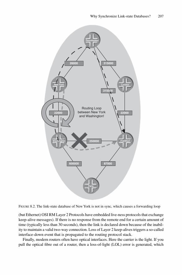
(but Ethernet) OSI RM Layer 2 Protocols have embedded live-ness protocols that exchangekeep-alive messages). If there is no response from the remote end for a certain amount oftime (typically less than 30 seconds), then the link is declared down because of the inabil-ity to maintain a valid two-way connection. Loss of Layer 2 keep-alives triggers a so-calledinterface-down event that is propagated to the routing protocol stack.
Finally, modern routers often have optical interfaces. Here the carrier is the light. If youpull the optical fibre out of a router, then a loss-of-light (LOL) error is generated, which
Why Synchronize Link-state Databases? 207
Pennsauken
Frankfurt
LondonNew York
Paris
22000
31500026000
250000
87000600000
22000
Routing Loopbetween New Yorkand Washington!
Washington
315000
FIGURE 8.2. The link-state database of New York is not in sync, which causes a forwarding loop

triggers an interface-down event. Serial interfaces, such as T1/E1, E3/T3, and Packet-over-SONET (POS) links, have strict framing requirements where even idle link data (no livepackets) have to be framed in a certain format. The advantage is that a receiver can detectproblems with the transmission framing even during idle periods without packet traffic. Thisis in contrast (for example) to Ethernet framing where idle periods (that is, where there is notransmission of packets) do not generate any signal. In addition, a loss-of-framing (LOF)error generates an interface-down event, which is propagated to the routing protocol stack.
Next, Washington schedules an SPF run based on the new topology information. TheWashington router re-calculates the new best paths to reach all IP sub-nets in the network.Both Washington and Frankfurt (working on the same task in parallel) on the other side willdisseminate their new view towards their neighbours. In the meantime, strange things beginto happen. Consider the traffic that flows from Washington to Amsterdam. Before the linkbreak, the traffic was routed over the intact link by way of Frankfurt. After the SPF recalcu-lation, the best path to Amsterdam is through New York and London. The problem is that thenetwork has not yet converged. So New York does not know about the changed topology.Based on New York’s latest SPF calculation (which still assumes that the link betweenWashington and Frankfurt is working), the best path to Amsterdam is through Washington.So traffic to Amsterdam is sent to New York, then it is sent back to Washington, then the traf-fic is sent again to New York and so on – a temporary or transient forwarding loop hasformed and the forwarding loop will persist until the updated topology view has arrived atNew York and New York can then recalculate its routing table. Based on the new routingtable, packets will be forwarded to London instead of being bounced back to Washington.
Synchronized link-state databases and the resulting routing tables are crucial forbringing packets closer to their final destination. IS-IS has two PDU types for synchron-izing databases: the CSNP (Complete Sequence Number Packet) and the PSNP (PartialSequence Number Packet). The following section illustrates how these packet types areused for synchronizing link-state databases over LAN and point-to-point circuits.Unfortunately the mechanisms and the use of CSNPs and PSNPs are different dependingon the media-type, which can be broadcast LAN or point-to-point.
8.2 Synchronizing Databases on Broadcast LAN Circuits
When IS-IS is activated on a router’s interface, the router first sends some IIHs to its neigh-bours to find out whether the circuit is capable of transporting packets in both directions. Ineach of its IIHs the router embeds what it believes to be the Designated Intermediate System(DIS). In Figure 8.3 you can see the structure of a LAN IIH and the DIS field at the end.
The DIS has a special role on an IS-IS broadcast circuit. Besides the modelling of theLAN as a topology graph (as you saw in Chapter 7 “Pseudonodes and Designated Routers”,the DIS has another function relevant to proper synchronization of link-state databaseson LANs. Periodically (typically every 10 seconds), the DIS has to send a directory of itslink-state database, which is received by all the routers on a LAN. Figure 8.4 shows thestructure of a CSNP PDU.
The CSNP Interval is not a hard coded value and can be changed accordingly. BothIOS and JUNOS permit to set the csnp-interval to an arbitrary value between
208 8. Synchronizing Databases

1–65535 seconds. Low values indicate a high load of generating and receiving CSNPs.The general recommendation on both platforms is to stick with the default values orincrease the csnp-interval if there are lots of broadcast circuits on the router whichneed to be supplied with fresh CSNPs. Note that in IOS you can set the csnp-intervalper level while JUNOS does not permit you to do that.
IOS configurationinterface GigabitEthernet0/2
isis csnp-interval 30 level-1
isis csnp-interval 40 level-2
!
JUNOS configurationprotocols {
isis {
Synchronizing Databases on Broadcast LAN Circuits 209
Intra-domain Touting Protocol Discriminator
Header Length Indicator
Version/Protocol ID Extension
0x83
Bytes
1
1
1
1
1
1
1
1
1
ID Length
PDU TypeR
0R
0R
0
PDU Version
Reserved
Maximum Area Addresses
6 (0)
1
3 (0)
0
Reserved
TLV section 0–1467
15, 16
27
circuittype 1, 2, 3
Source ID
Holding Time
PDU Length
PriorityR
Designated IS LAN-ID
1
ID Length (6)
2
2
1
ID Length (6) � 1
FIGURE 8.3. Each IS-IS router sends what it believes is the Designated Intermediate System at agiven time

interface ge-2/0/0.0 {
csnp-interval 30;
interface lo0.0;
}
}
You can verify the settings by issuing a show isis interface <ifname>detail command on JUNOS.
hannes@London> show isis interface ge-0/2/0.0 detail
IS-IS interface database:
ge-0/2/0.0
Index: 1, State: 0x6, Circuit id: 0x2, Circuit type: 3
LSP interval: 100ms, CSNP interval: 10s
Level Adjacencies Priority Metric Hello (s) Hold (s) Designated Router
1 2 64 1200 9.000 40 Amsterdam.02 (not us)
2 1 64 22000 3.000 40 London.02 (us)
210 8. Synchronizing Databases
Intra-domain Routing Protocol Discriminator
Header Length Indicator
Version/Protocol ID extension
0x83
Bytes
1
1
1
1
1
1
1
1
1
ID Length
PDU TypeR0
R0
PDU Version
Reserved
Maximum Area Addresses
6 (0)
1
3 (0)
0
TLV section 34–1459
24, 25
33
Source ID
Start LSP-ID
PDU Length
End LSP-ID
2
ID Length (6) � 1
ID Length (6) � 2
ID Length (6) � 2
R0
1, 2, 3
FIGURE 8.4. CSNP PDUs are used for conveying the headlines of the link-state database
You cannot verify the csnp-interval settings on an IOS router because the csnp-interval is not displayed under the show clns interface <ifname> command.
The CSNP on LAN circuits is sent using the well-known functional address AllL1ISs(0180:c200:0014) or to the well-known functional address AllL2ISs (0180:c200:0015)depending on the IS-IS level. The IS-IS common header that provides the receiver withthe following information starts the CSNP PDU:
• Header length (this is always 33 bytes for the CSNP header)• IS-IS protocol version that is used (always 1)• Length of the System-ID (0 means the standard 6 bytes)• Level (L1 CSNPs use PDU type 24, L2 PSNPs use PDU type 25)• CSNP protocol version that is used (always 1)• Number of area addresses that this IS supports (0 means support for 3 addresses)
The CSNP header holds the following information:
• PDU length (this is the length of the entire PDU including the common header, theCSNP header, and the payload)
• Source-ID (the System-ID plus a trailing zero byte)• The Start LSP-ID plus the End LSP-ID (The LSP-ID describe Elements in the link-
state database of the router)
After the CSNP header the rest of the PDU is filled using TLVs. You can learn moreabout TLVs in Chapter 11. In CSNP PDUs only two TLVs are used. The LSP-ID TLV #9is used for link-state database synchronization and the Authentication TLV #10 are usedfor integrity checking.
If the entire LSP database fits into a single CSNP PDU, meaning there are no morethan 90 LSP-IDs in the CSNP PDU, then the Start LSP-ID is set to 0000.0000.0000.00-00and the End-LSP-ID is set to FFFF.FFFF.FFFF.FF-FF (the entire range possible). This ishow the sender tells the receiver that this CSNP contains the full range of LSP-IDs that arepresent in the sender’s database. Where does the maximum number of 90 LSP-IDs perCSNP PDU come from? Recall that 15 LSP-entries fill an LSP-entry TLV with 240 bytes.Add 2 bytes for TLV overhead to come up with 242 bytes. The LSP-entry TLV can repeatup to 6 times until the packet is completely full. Now, 6 * 242 � 1452 bytes plus 33 bytesof header length � 1485 bytes. Therefore, 6 LSP-entry TLVs per packet * 15 LSP-IDsper LSP-entry TLV, comes out to 90 LSP-IDs per packet:
Link-state databases that contain more than 90 entries send more than one CSNP PDU.The first CSNP PDU, Start LSP-ID, is set to 0000.0000.0000.00-00 and the End LSP-IDof the last CSNP PDU is set to FFFF.FFFF.FFFF.FF-FF. This all ones ending tells thereceiver that this CSNP is the last one to describe the link-state database, and the trans-mission of LSP-IDs is completed. Between the first PDU and the last, other CSNP-PDUsinsert the LSP-ID of the first and the last LSP-ID reported using the LSP-entry-TLV #9in the CSNP header in the Start LSP-ID and End LSP-ID fields. It is assumed that theLSP-IDs are ordered by LSP-ID and they arrive in sequence.
6LSP-Entry TLVs
packet * 15
LSP-IDs
LSP-Entry TLV 90
LSP-IDs
packet�
Synchronizing Databases on Broadcast LAN Circuits 211

CS
NP
TL
Vs
1921
.680
1.40
01.0
0-00
Seq
uen
ce 0
x289
Lif
etim
e
324
Ch
ecks
um
0xf
c11
1921
.680
2.71
52.0
0-00
Seq
uen
ce
0x2b
Lif
etim
e 1
2058
Ch
ecks
um
0x6
2a1
CS
NP
Hea
der
:S
tart
LS
P-I
D00
00.0
000.
0000
.00-
00E
nd
LS
P-I
D19
21.6
802.
7152
.00-
00
CS
NP
TL
Vs
1921
.681
7.71
39.0
0-00
Seq
uen
ce 0
x135
Lif
etim
e 4
9653
Ch
ecks
um
0xc
c16
1921
.681
7.82
22.0
0-00
Seq
uen
ce 0
x2c4
Lif
etim
e 3
8894
Ch
ecks
um
0x7
80c
CS
NP
Hea
der
:S
tart
LS
P-I
D19
21.6
817.
7139
.00-
00E
nd
LS
P-I
D19
21.6
817.
8222
.00-
00
CS
NP
TL
Vs
1921
.681
7.82
23.0
0-00
Seq
uen
ce 0
xcf6
Lif
etim
e 6
3449
C
hec
ksu
m 0
x948
f
1921
.681
7.90
58.0
0-00
Seq
uen
ce 0
x2a0
9 L
ifet
ime
634
49C
hec
ksu
m 0
xb91
8
CS
NP
Hea
der
:S
tart
LS
P-I
D19
21.6
817.
8223
.00-
00E
nd
LS
P-I
D19
21.6
817.
9058
.00-
00
CS
NP
CS
NP
Hea
der
:S
tart
LS
P-I
D19
21.6
818.
1211
.00-
00E
nd
LS
P-I
Dff
ff.f
fff.
ffff
.ff-
ff
TL
Vs
1921
.681
8.12
11.0
0-00
Seq
uen
ce 0
x357
L
ifet
ime
333
84C
hec
ksu
m 0
xb69
4
1921
.681
8.12
55.0
0-00
Seq
uen
ce 0
x38a
L
ifet
ime
252
25C
hec
ksu
m 0
xcab
a
t
CS
NP
#1
(firs
t)
CS
NP
#2
CS
NP
#3
CS
NP
#4
(last
)
FIG
UR
E8.
5. L
ink-
stat
e da
taba
ses
bigg
er th
an 9
0 L
SPs
need
mul
tiple
CSN
P PD
Us
for
a fu
ll re
port
212

Synchronizing Databases on Broadcast LAN Circuits 213
Figure 8.5 shows an example of a multi-packet CSNP, which is sent as a sequence offour frames. The first CSNP has the Start LSP-ID set to all zeros. The End LSP-ID is set tothe last LSP-ID that is reported in the first CSNP (1921.6802.7152.00-00). The inter-mediate CSNPs set their Start and LSP-ID fields according to the first and last LSP-IDthat is reported in the PDU. Finally, the last CSNP of the full update sets the End-LSP IDto all ones (FFFF.FFFF.FFFF.FF-FF) indicating that the full-report of all LSP-IDs is nowcompleted.
The payload section of the CSNP PDU is filled with an information element called theLSP Entry. The LSP Entry is placed in the CSNP PDU by use of TLV encoding. You canfind more information about TLV encoding in Chapter 11 “TLVs and sub-TLVs”. Figure 8.6shows the structure of the LSP Entry TLV. The TLV header consists of two bytes – theType and the Length value. The Type value is #9 and the Length value is always a mul-tiple of 16. The LSP Entry is a structure of 16 bytes that can be repeated up to 15 timesin a TLV. The LSP Entry holds the header information of an LSP in the link-state data-base. This information is:
• LSP-ID (6 byte System-IDs plus 1 byte node-ID plus 1 byte fragment number)• Sequence number (4 bytes)• Remaining lifetime (2 bytes)• Checksum of the corresponding LSP (2 bytes, standard Fletcher checksum)
By using these four parameters, an LSP can uniquely be identified in a link-state database.Additionally, for each LSP, two informative flags are kept for each circuit in order to con-trol flooding, re-flooding, and acknowledging LSP updates. These two flags are called
TLV Type
TLV Length
Remaining Lifetime
9
Bytes
1
1
ID Length (6) � 2
2
4
2
LSP-ID
Sequence Number
Checksum
N * 16
Remaining Lifetime
ID Length (6) � 2
2
4
2
LSP-ID
Sequence Number
Checksum
FIGURE 8.6. The LSP Entry TLV is a container for LSP headline figures like Sequence Number,Lifetime and Checksum
the SRM (Send Routing Message) and the SSN (Send Sequence Numbers) flag and aredefined in ISO 10589. If the SRM is set on a link, this means that the corresponding LSPhas to be sent out on that link. If the SSN flag is set, the corresponding LSP should beincluded in the next PSNP PDU. Note that these two flags are kept strictly internal to therouter. They do not show up in any PDU that the router generates. However, what theflags do is influence the link on which LSPs and PSNPs are being sent.
Getting back to the header fields proper, the DIS extracts this header information fromits link-state database and packages up to 15 LSP-IDs in a single TLV. Given an IS-ISMTU of 1497 bytes over Ethernet LANs, a DIS can package up to 6 times an LSP EntryTLV #9, resulting in up to 90 LSP-IDs in a single CSNP. So even in the largest networksin the world there are just a few CSNP packets going over the wire every 10 seconds. Next,each router on the LAN compares its own link-state database to the CSNP received fromthe DIS. If the DIS reports the same sequence number for an LSP-ID, then everything isfine. If not, then there are three basic mismatch conditions that can occur:
• The CSNP reporting an older version of a LSP• The CSNP reporting a more recent version of a LSP• The CSNP reporting an unknown LSP
If the CSNP received is an older version, then the action is simple. Because it appears thatthe DIS is not up to date, just tell the DIS about the new version of the LSP by re-floodingthe most recent version of the LSP onto the LAN. Figure 8.7 illustrates the chain of events.Router B notices that Router A is still carrying an older version of the LSP RouterX.00-00in its link-state database. So Router B floods the LSP RouterX.00-00 with the most recentsequence number (0x7a). Note, however, that no receiver acknowledges the re-flooded LSP.This principle is sometimes referred to as implicit acknowledgement. So how can the updatebe made more reliable? Just wait for a maximum of 10 seconds, which is the regular CSNPinterval. If the LSP RouterX.00-00 is mentioned in the CSNP with the sequence number(0x7a) and the checksum is correct as well, then the update is successful. IS-IS is veryunique in that respect, in that IS-IS tries to keep state-related information very low. Theperiodic transmission of CSNPs is fundamental to well-synchronized databases.
If the CSNP reported is a more recent version of the LSP, the receiving router needs totell the DIS that it is out of sync by internally setting the SRM flag for this LSP. Settingthe SRM flag triggers the sending of a PSNP to the DIS. Figure 8.8 shows the basic struc-ture discussed earlier in this section. The only difference from the CSNP PDU is that thePSNP PDUs are using different code points than the CSNP. IS-IS PDU type 24 indicatesa Level-1 PSNP and IS-IS PDU type 25 is used for a Level-2 PSNP. Once the PSNP PDUis formed, all the LSP-IDs that are more recent are packaged again in TLV #9s. Once thePSNP PDU is received at the DIS, the DIS re-floods the most recent version of the requestedLSP back onto the LAN. Figure 8.9 illustrates the chain of events. Router A reports anLSP (RouterX-00.00) that is unknown to Router B. So Router B sends a PSNP mentioningRouterX-00.00, but with a Sequence Number 0, Checksum 0, and Lifetime 0. SequenceNumber 0 is specially reserved for the case where a router wants to get its database synchron-ized. By setting Sequence Number, Lifetime, and Checksum to zero, a router on a LAN isindicating that it wants to get a copy of that LSP. Therefore Router A re-floods the latestcopy of the LSP RouterX.00-00 onto the LAN. Once again, this re-flooding is done using
214 8. Synchronizing Databases

Synchronizing Databases on Broadcast LAN Circuits 215
Router A(DIS)
Router B
tt
CSNPRouterX.00-00
Sequence # 0x79Lifetime 974
Checksum 0x64fa
LSPRouterX.00-00
Sequence # 0x7aLifetime 1146
Checksum 0x3cce
CSNPRouterX.00-00
Sequence # 0x7aLifetime 1136
Checksum 0x3cce
10s
FIGURE 8.7. Router A reports an outdated LSP in its CSNP, which causes a re-flood of Router B andfinally Router A reports that it is in sync again by reporting the latest sequence number
Intra-domain Routing Protocol Discriminator
Header Length Indicator
Version/Protocol ID Extension
0x83
Bytes
1
1
1
1
1
1
1
1
1
ID length
PDU TypeR0
R0
R0
PDU Version
Reserved
Maximum Area Addresses
6 (0)
1
3 (0)
0
TLV section 18–1475
26,27
17
Source ID
PDU Length 2
ID Length (6) � 1
FIGURE 8.8. The PSNP PDU reports just a subset of the LSP in the link-state database

“implicit acknowledgments”. What might happen is that the LSP does not arrive at RouterB, but this is not a problem: Router B would simply resend the PSNP after 5 seconds.
If the DIS reports a new or unknown LSP-ID in its CSNP PDU, then the router thatdetects the mismatch sends a PSNP requesting the missing LSP-ID by setting the threefields of Sequence Number, Lifetime and Checksum to zero, indicating to the receiver thatthe sender does not know anything specific about this LSP. The DIS will again re-flood themissing LSP. This procedure is typically executed when a new router becomes online.
Synchronization of LSPs on LAN segments is both simple and lean. Contrary toOSPF, which needs to keep a lot of state information for synchronizing link-state data-bases, IS-IS uses only two flags for each link: the SRM and the SSN flag.
Next, IS-IS synchronization on point-to-point circuits is discussed. Point-to-pointlinks make different use of PSNPs and CSNPs than broadcast links, such as LANs.
8.3 Synchronizing Databases on p2p Links
All link-state routing protocols start their first synchronization after one common event:once an adjacency is declared up. Once an adjacency is up on a point-to-point link, the router
216 8. Synchronizing Databases
Router A(DIS) Router B
tt
CSNPRouterX.00-00
Sequence # 0x79Lifetime 974
Checksum 0x64fa
PSNPRouterX.00-00
Sequence # 0x0Lifetime 0
Checksum 0x0000
CSNPRouterX.00-00
Sequence # 0x7aLifetime 1136
Checksum 0x3cce
10s
LSPRouterX.00-00
Sequence # 0x7aLifetime 1146
Checksum 0x3cce
FIGURE 8.9. Router B requests a re-flood of new or unknown LSPs by sending a PSNP withSequence Number and Checksum set to zero

will jitter a 5-second timer by 25 per cent before sending a CSNP from its own database.Jittering by 25 per cent means that the router computes a random number between 75–100per cent of the underlying timer; 75 per cent of 5 seconds equals 3.75 seconds. The resultis a random timer between 3.75 and 5 seconds. The other router does the same thing.Jittering timers decouple any kind of synchronization effects causing traffic spikes betweenthe two routers. See Figure 8.10 with a hub router and many spoke routers for an illustrationof how immediate dispatch of PDUs might harm IS-IS peak load performance. If allspoke routers immediately generate a CSNP after the adjacency is up, then the hub routerhas to process a large number of CSNPs in a relatively short timeframe. This leads to ashort-term peak-load on the hub router. Also, sending all this control traffic at once mightharm other user traffic that runs on the physical link. Just imagine if the spoke links werenot physical links but logical Frame Relay circuits (DLCIs) all on one physical link. Thisresult might be short-term congestion or an abrupt increase in delay for user traffic.However, if routers jitter the timer before the CSNP is sent after the adjacency-up event,this reduces the short-term congestion and peak CPU utilization. After routers have sentthe CSNP it will hang around for a few seconds until routers get the CSNP from the other
Synchronizing Databases on p2p Links 217
Hub Router
Spoke Router #1
Spoke Router #2
Spoke Router #3
Spoke Router #4
Spoke Router #N
t
CSNP
0 Adj-UP
t
CSNP
0 Adj-UP
t
CSNP
0 Adj-UP
Spoke Router #1
Spoke Router #2
Spoke Router #N
t
CSNP
0 Adj-UP
t
CSNP
0 Adj-UP
t
CSNP
0 Adj-UP
Spoke Router #1
Spoke Router #2
Spoke Router #N
All CSNPs hit the Hub Routerat the same time
CSNPs are spreadover a time window
FIGURE 8.10. Jittering timers helps to spread the processing load over a broader time window
neighbour. If the router does not wait for the other CSNP, then another CSNP is sched-uled after 5 seconds (minus jitter) and so on.
However, if the sending router does receive the remote end’s CSNP, then the router cancompute the differences between the two link-state databases. For any LSPs that are miss-ing with respect to the sender’s link-state database, no action is taken. Just sending theCSNP is enough because the other router will see the sender’s CSNP and realize that inthe sender’s link-state database there are a couple of LSPs missing. What does the otherrouter do once detecting a database mismatch? – It re-floods the missing LSPs, of course.
On point-to-point links, the LSP updates are required to be reliable and therefore mustbe acknowledged. This is achieved by setting the SRM flag internally for the LSP beingsent. Setting the SRM flag translates into a waiting for an acknowledgement state. Assoon as an acknowledgement for the LSP arrives (by a listing in a PSNP or CSNP), theSRM flag is cleared, or it is removed from the retransmission list. If no acknowledgementarrives, then the IS-IS router will periodically check the SRM flags on all links andretransmit LSPs that have not yet been acknowledged.
See Figure 8.11 for the detailed chain of events that happen once the LSP-IDs in theCSNPs do not match. Router A sends its CSNP. Router B sends its CSNP. Next, Router Are-floods LSP 0000.0000.0005.00-00. Router B re-floods LSP 0000.0000.0006.00-00and LSP 0000.0000.0006.00-01. Then, Router B sends a PSNP containing LSP-ID0000.0000.0005.00-00 formatted in the LSP Entry TLV #9 as an acknowledgement forthe LSP. Finally, Router A sends a PSNP containing the LSP-IDs 0000.0000.0006.00-00and 0000.0000.0006.00-01 packaged in the LSP Entry TLV #9 as an acknowledgementfor the two LSP fragments.
ISO 10589 does not mandate sending CSNPs except for the initial synchronizationprocedure on point-to-point links. However, sending CSNPs periodically after the startupevent results in better synchronization of the link-state database. The following sectionexplains how IS-IS link-state database synchronization is improved by sending periodicCSNPs.
8.4 Periodic Synchronization on p2p Circuits
In the IS-IS world of ISO 10589, there is an assumption that each link that can carry IS-IS Hellos can also carry IS-IS LSPs. At first sight, the previous sentence might soundodd and you may think, “Sure, why should a link that can carry a certain IS-IS packettype, not carry arbitrary IS-IS packet types?” But as demonstrated in Chapter 6“Generating, Flooding and Ageing LSPs”, there can be situations where the IS-IS flood-ing topology may get pruned. Mesh-groups are a good example of this situation. Certainredundant links are removed from the flooding topology in mesh-groups. As a result,there might be situations where parts of the network may get de-synchronized becausethe LSPs do not get through. In this environment especially, it might be a good idea tosend some additional CSNPs to make sure that the neighbours are well synchronized. Ofthe two implementations of IS-IS from Cisco Systems and Juniper Networks that are thesubject of this book, only Juniper Networks implements a more robust synchronizationscheme.
218 8. Synchronizing Databases

P2p
cir
cuit
tt
CS
NP
Adj
-UP
5s
del
ay25
% ji
tter
0000
.000
0.00
06.0
0-00
Seq
uen
ce 0
x101
Lif
etim
e 10
22C
hec
ksu
m 0
x99f
e
CS
NP
LS
P
PS
NP
PS
NP
5s
del
ay25
% ji
tter
0000
.000
0.00
05.0
0-00
Seq
uen
ce 0
x142
Lif
etim
e 10
99C
hec
ksu
m 0
xab
d4
0000
.000
0.00
05.0
0-00
Seq
uen
ce 0
x143
Lif
etim
e 11
88C
hec
ksu
m 0
x318
b
0000
.000
0.00
06.0
0-00
Seq
uen
ce 0
x102
Lif
etim
e 11
78C
hec
ksu
m 0
x881
2
0000
.000
0.00
05.0
0-00
Seq
uen
ce 0
x143
Lif
etim
e 11
88C
hec
ksu
m 0
x318
b
LS
P
0000
.000
0.00
06.0
0-00
Seq
uen
ce 0
x102
Lif
etim
e 1
178
Ch
ecks
um
0x8
812
Mis
mat
ch in
CS
NP
!O
ur v
ersi
on o
f00
00.0
000.
0006
.00-
00is
new
er
Ok
– go
t it !
sen
d a
PS
NP
as
AC
K
Ok
– go
t it !
sen
d a
PS
NP
as
AC
K
Mis
mat
ch in
CS
NP
!O
ur v
ersi
on o
f00
00.0
000.
0005
.00-
00is
new
er
Adj
-UP
FIG
UR
E8.
11. A
fter
the
3-w
ay h
ands
hake
eac
h ro
uter
sen
ds a
CSN
P. I
f th
e tw
o ro
uter
s’L
SDB
s ar
e de
-syn
ced
both
rou
ters
will
L
SP-r
e-flo
od th
e m
issi
ng L
SPs
and
send
sub
sequ
ent P
SNPs
for
ack
now
ledg
ing
thos
e
219

220 8. Synchronizing Databases
JUNOS software periodically transmits CSNPs at both IS-IS levels on all (includingp2p) circuits. The time base is not fixed, that is, the JUNOS software does not transmitits CSNP at a hard-coded rate. What JUNOS software does is take a base value of 5 sec-onds and multiplies that number by the number of interfaces that have adjacencies in theUp state. This technique is called smearing because one timer is smeared over severalinterfaces. For an illustration of this technique, look at Figure 8.12. The router has sevenadjacencies, four interfaces (two broadcast links and two point-to-point circuits). Eachinterface carries one or more adjacencies in the Up state. Therefore, 5 seconds times 4interfaces � a 20-second timer started on each of the interfaces. On average, every 5 sec-onds, a CSNP is sent, resulting in good synchronization. Even if a link is pruned from theflooding topology, for example by use of mesh-groups, periodical CSNPs ensure goodsynchronization.
Fortunately ISO 10589 neither mandates the sending of periodic CSNPs nor does itstrictly discourage sending them. This hole in the specification is utilized by the smearinghack described previously. There are no known interoperability issues between Cisco IOSand JUNOS software. Except for the support calls that are generated by NOC teams that findthe amount of CSNPs being generated suspiciously high, there are no relevant issues.
A typical show isis statistics output resulting from hooking up a JUNOS toan IOS router looks like this on the JUNOS side.
JUNOS command outputjuniper@London> show isis statistics
IS-IS statistics for London:
PDU type Received Processed Drops Sent Rexmit
LSP 41034 41034 0 95 0
IIH 36 36 0 34 0
CSNP 1 1 0 420859 0
PSNP 87 87 0 5125 0
Unknown 0 0 0 0 0
Totals 41159 41159 0 426113 0
Total packets received: 41158 Sent: 426079
SNP queue length: 0 Drops: 0
LSP queue length: 0 Drops: 0
SPF runs: 10772
Fragments rebuilt: 104
LSP regenerations: 27
Purges initiated: 0
London only received a single CSNP and sent hundreds of thousands of CSNPs. Bylooking at this output you can easily see that there must be lots of Cisco routers on theother end, which typically just generate a single CSNP, once an adjacency comes up.
Finally, it should be noted that generating CSNPs comes at almost no cost because theyare not difficult to build. CSNPs can be constructed by traversing internal tables in a singlepass, and require no complex multi-field operations like checksum calculations. In addition,

CS
NP
20s
tt
CS
NP
tt
CS
NP
CS
NP
CS
NP
CS
NP
CS
NP
CS
NP
020
05
2 50
1030
015
35
20s
20s
20s
FIG
UR
E8.
12. J
UN
OS
send
s a
peri
odic
al C
SNP
each
5s
per
rout
ing
proc
ess
and
dist
rib u
tes
the
load
acr
oss
all a
ctiv
e in
terf
aces
221

the content of the CSNP does not change frequently. Therefore the CSNP frame can bepre-computed and when the CSNP timer fires, the pre-computed frames are just transmittedover the wire. The pre-computed PDU needs only to change if there is an update in thelink-state database. To be completely honest, CSNP construction is not that simple: the LSPlifetimes need to be adjusted as well, because all the LSPs age every second – however,once again inserting of lifetimes values is just a simple copy operation.
8.5 Conclusion
CSNPs and PSNPs are very simple and powerful mechanisms to synchronize IS-IS link-state databases. In contrast to OSPF, almost no state information needs to be kept forsynchronizing link-state databases. Just two bits per LSP/per interface are required. Theopenness of the base IS-IS spec ensures that more robust synchronization mechanismscan be implemented and all surrounding routers can cooperate and interoperate.
Because of the inherent simplicity of the IS-IS protocol there are practically no inter-operability issues for database synchronization. Ultimately, a robust synchronizationscheme is the main prerequisite for loop-free forwarding paths through the network.
222 8. Synchronizing Databases

10
SPF and Route Calculation
In order for the hop-by-hop routing paradigm to work, link-state routers need a commonalgorithm to determine a loop-free path to all destinations in a network. In this chapteryou will gain insight as to how the IS-IS related route-calculation and route-resolutionalgorithms work. There will be a step-by-step explanation of the main three elements inthe route calculation process that is SPF calculation, route resolution and prefix insertion.
The SPF calculation process has been practically demonized in the past. There is noneed to view this process negatively, in the authors’ opinion. This chapter includes a per-formance assessment of each of the three elements needed for SPF calculation to correctthis unfortunate perception. Also, common router OS implementation knobs for mitigatingthe CPU overload side-effects of the SPF calculation and route resolution will be discussed.
Finally there will be an implementation assessment of the most dominant perform-ance-related element of the process, which is prefix insertion. The two common schemesfor prefix insertion are presented and finally the cost of inserting a prefix and the metricsof current router hardware will be highlighted.
10.1 Route Calculation
From the time that a link-state PDU arrives to the time traffic is flowing through thechanged path in a router, a lot of actions need to be taken. Figure 10.1 shows the threedifferent steps that are applied for each route.
First, the SPF calculation needs to be run. Depending on the location in the networktopology and which information has changed (topology, prefix), there are three choicesof SPF runs:
• Full• Partial• Incremental
247
SPFcalculation
Routeresolution
Prefixinsertion
FIGURE 10.1. The three operations for calculating routes
Then, after executing the SPF calculation, the router needs to find out if there aredependent routes.
The route resolver determines if a change of the IS-IS-supplied topology and routesalso results in a change of dependent routes. Routing protocols like BGP rely on a workingIGP to map the reachability information to a topology in order to calculate the path costproperly. Finally, after the affected dependent routes have been determined, the routerproceeds to the third stage, which is prefix insertion.
At the prefix insertion stage the router inserts, deletes or changes prefixes of alladdress families (IPv4, IPv6) and their corresponding Next-hops, then downloads thenew forwarding tables to the line-cards and ASICs of the packet forwarding complex ofthe router.
The next sections explore all three elements both from a theoretical and practical per-spective. At the end of each section performance considerations for the network designerare highlighted.
10.2 The SPF Algorithm
The Shortest Path First algorithm was invented and first documented by Edser Dijkstra,a Dutch mathematician who was researching the topic of graph theory and looking for analgorithm to determine the shortest spanning distance between two points on a graph.The SPF algorithm is perhaps one of the best-analyzed algorithms in computer science,and its scaling properties are well understood. There are many resources available on theInternet that explain and illustrate how the SPF algorithm works. A good tutorial to learnmore about the algorithm, even running through an animated SPF calculation, can befound at http://www.tutor.ms.unimelb.edu.au/dijkstra/dijkstra.html
Briefly, SPF is based on a database of node-to-node costs and, using three lists, theSPF algorithm can determine the shortest path to all nodes in N steps, where N is thenumber of nodes in the network.
10.2.1 Working PrincipleThe SPF algorithm maintains three lists:
• UNKNOWN• TENTative• PATHs
All nodes currently in the link-state database are first moved to the UNKNOWN list.The node currently being evaluating is placed on the TENTative list, and the local routerexecuting the SPF calculation puts itself on the TENTative list. The TENTative list consistsof triplets in the form of neighbour, neighbours-cost and cost to root (the router runningSPF). Once SPF determines the best path (lowest cost back to the root) to a node, thenode is moved to the PATHs list. The PATHs list sometimes is called the Known list.
248 10. SPF and Route Calculation

The list of explored PATHS starts at zero. Next, a loop of at most N steps starts, whereN is the number of nodes in the link-state database. Each loop through the algorithm hasthese steps:
1. Find the node with the lowest cost and move it into PATHs2. Find all neighbours reachable from that node and move the neighbours from
UNKNOWN into TENTative, but …3. Before a node is moved from UNKNOWN into TENTative, apply a two-way check. If
Node A claims that it can see Node B, re-verify that Node B also reports to see Node A.If not, ignore that adjacency.
4. For each node that moves onto the TENTative list, maintain the cost to get there andstore the first-hop information. The first-hop is needed for populating the routing-tablewith routes when SPF is done. The forwarding-engine of a router thinks only in termsof prefixes and directly connected next-hops (the first-hop).
10.2.2 ExampleThe SPF algorithm can be very abstract. Consider the sample topology shown inFigure 10.2. For a better illustration of SPF calculation, we will do an SPF calculation
The SPF Algorithm 249
UNKNOWN List
Area 49.0001Level 2-only
oc192/STM-64
87000
oc12/STM-4
600000
oc192/STM-64
250000
oc768/STM-256
22000
oc768/STM-256
22000
oc48/STM-16
315000
oc48/STM-16
315000
oc192/STM-64
26000
315000Pennsauken-�London
Pennsauken-�Frankfurt
Pennsauken-�New York
315000
26000
315000London-�Pennsauken
London-�Frankfurt 22000
Frankfurt-�London 22000
Frankfurt-�Pennsauken 315000
Frankfurt-�Washington D.C. 250000
Frankfurt-�Paris 87000
Paris-�Frankfurt 87000
Paris-�Washington D.C. 600000
Washington D.C.-�Paris 600000
Washington D.C.-�Frankfurt 250000
Washington D.C.-�New York 22000
New York-�Washington D.C. 22000
New York-�Pennsauken 26000
TENTative List
LSDB entry cost cost to root
empty 0 0
PATH List
empty - 0
Destination via cost to root
Pennsauken
Frankfurt
London
Washington
New York
Paris
FIGURE 10.2. At initialization all information in the LSDB is moved on the UNKNOWN list

just as a router in this sample topology would, in this example, the Pennsauken router.The figure shows all the Level-2 routers and eight links to connect them. Those linkshave speeds varying from OC-12/STM-4 (622Mbit/s) up to OC-768/STM-256 (40Gbit/s).The link cost has been assigned on a composite bandwidth/cost scheme. (Thosebandwidth-to-IGP cost values are taken from Figure 12.10 in Chapter 12 “IP ReachabilityInformation.”)
The full link-state database consists of six routers reporting eight links. Due to theseeight links, the router holds 8 * 2 � 16 unidirectional link-states in the link-state data-base (LSDB). At the beginning of the SPF calculation, all 16 links are moved, togetherwith their respective cost field, into the UNKNOWN list, as shown in Figure 10.2.
Then the list of explored PATHs is cleared and each router performing the SPF calcula-tion puts itself as the first entry into the TENTative list. In our example, we will executethe SPF calculation from Pennsauken’s point of view as illustrated in Figure 10.3. Alladjacencies that are reported via Pennsauken are moved into the TENTative list.
250 10. SPF and Route Calculation
87000600000
250000
22000
oc768/STM-256
22000
315000
31500026000
315000Pennsauken-�London
Pennsauken-�Frankfurt
Pennsauken-�New York
315000
26000
315000London-�Pennsauken
London-�Frankfurt 22000
Frankfurt-�London 22000
Frankfurt-�Pennsauken 315000
Frankfurt-�Washington D.C. 250000
Frankfurt-�Paris 87000
Paris-�Frankfurt 87000
Paris-�Washington D.C. 600000
Washington D.C.-�Paris 600000
Washington D.C.-�Frankfurt 250000
Washington D.C.-�New York 22000
New York-�Washington D.C. 22000
New York-�Pennsauken 26000
TENTative List
PATH List
LSDB entry cost
315000Pennsauken-�London 315000
Pennsauken-�Frankfurt 315000 315000
Pennsauken-�New York 26000 26000
26000
via
2
1
Frankfurt
Pennsauken
oc192/STM-64 oc48/STM-16
New Yorkoc48/STM-16
London
Area 49.0001Level 2-only
oc768/STM-256
Washington
oc192/STM-64
oc12/STM-4 oc192/STM-64
Paris
UNKNOWN List
cost to root
Destination
New York New York
cost to root
FIGURE 10.3. New York has the least-cost path to root and is moved onto the PATH list
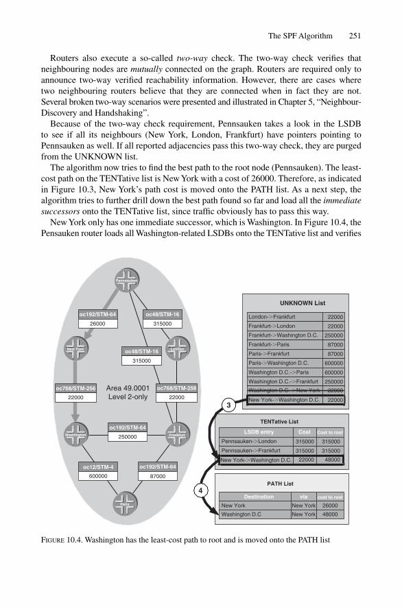
The SPF Algorithm 251
Routers also execute a so-called two-way check. The two-way check verifies thatneighbouring nodes are mutually connected on the graph. Routers are required only toannounce two-way verified reachability information. However, there are cases wheretwo neighbouring routers believe that they are connected when in fact they are not.Several broken two-way scenarios were presented and illustrated in Chapter 5, “Neighbour-Discovery and Handshaking”.
Because of the two-way check requirement, Pennsauken takes a look in the LSDB to see if all its neighbours (New York, London, Frankfurt) have pointers pointing toPennsauken as well. If all reported adjacencies pass this two-way check, they are purgedfrom the UNKNOWN list.
The algorithm now tries to find the best path to the root node (Pennsauken). The least-cost path on the TENTative list is New York with a cost of 26000. Therefore, as indicatedin Figure 10.3, New York’s path cost is moved onto the PATH list. As a next step, thealgorithm tries to further drill down the best path found so far and load all the immediatesuccessors onto the TENTative list, since traffic obviously has to pass this way.
New York only has one immediate successor, which is Washington. In Figure 10.4, thePensauken router loads all Washington-related LSDBs onto the TENTative list and verifies
87000600000
250000
22000 22000
315000
31500026000London-�Frankfurt 22000
Frankfurt-�London 22000
Frankfurt-�Washington D.C. 250000
Frankfurt-�Paris 87000
Paris-�Frankfurt 87000
Paris-�Washington D.C. 600000
Washington D.C.-�Paris 600000
Washington D.C.-�Frankfurt 250000
Washington D.C.-�New York 22000
New York-�Washington D.C. 22000
TENTative List
LSDB entry Cost
315000Pennsauken-�London 315000
Pennsauken-�Frankfurt 315000 315000
22000New York-�Washington D.C. 48000
PATH List
New York 26000
Destination via cost to root
Washington D.C 48000
3
4
Pennsauken
oc192/STM-64 oc48/STM-16
New York oc48/STM-16 London
oc768/STM-256 Area 49.0001Level 2-only
oc768/STM-256
Washington
oc192/STM-64
oc12/STM-4 oc192/STM-64
Frankfurt
Paris
UNKNOWN List
Cost to root
New York
New York
FIGURE 10.4. Washington has the least-cost path to root and is moved onto the PATH list

each claimed adjacency using the two-way check again. After the two-way check, theentries are deleted from the UNKNOWN list. The link from New York to Washingtonhas a cost of 22000 and the link from the Pennsauken root to New York comes to26000, which the router already determined. The aggregate path cost therefore is22000 � 26000 � 48000 which is written into the cost-to-root field. Washington is theshortest path to the root and is therefore moved onto the PATH list.
Next, Washington’s successors are explored. In Figure 10.5, the nodes Paris and Frankfurtare moved onto the TENTative list, but only after satisfying the two-way condition. Two-way-check-related LSDB entries are then deleted from the UNKNOWN list. Now, thereare two paths to Frankfurt on the TENTative list. One path goes directly and one goes viaNew York. SPF adds the shortest path by cost, which is via New York. Frankfurt via NewYork moves onto the PATH list with a cost of 298000. Additionally, the higher cost pathto Frankfurt, which is the direct OC-48/STM-16 link, is deleted from the TENTative list.
In Figure 10.6, the last step of the SPF calculation is described. The last node that has been put onto the PATH list is Frankfurt. Therefore, all nodes that are reported
252 10. SPF and Route Calculation
UNKNOWN List
87000600000
250000
22000 22000
315000
31500026000
London-�Frankfurt 22000
Frankfurt-�London 22000
Frankfurt-�Washington D.C. 250000
Frankfurt-�Paris 87000
Paris-�Frankfurt 87000
Paris-�Washington D.C. 600000
Washington D.C.-�Paris 600000
Washington D.C.-�Frankfurt 250000
TENTative List
LSDB entry cost
315000Pennsauken-�London 315000
Pennsauken-�Frankfurt 315000 315000
Washington D.C.-�Paris 600000
Washington D.C.-�Frankfurt 250000
648000
298000
PATH List
New York 26000
Destination via
Washington D.C 48000
Frankfurt 298000
5
6
Pennsauken
oc192/STM-64 oc48/STM-16
New York oc48/STM-16 London
oc768/STM-256 Area 49.0001Level 2-only
oc768/STM-256
Washington
oc192/STM-64Frankfurt
oc12/STM-4 oc192/STM-64
Paris
cost to root
cost to root
New York
New York
New York
FIGURE 10.5. Frankfurt is routed via New York although a direct line exists

The SPF Algorithm 253
via Frankfurt are further examined. The two remaining LSDB entries Frankfurt reportsare the adjacencies to Paris and London. After passing the two-way check, the two linksare moved onto the TENTative list. There are two ways to London: one direct link andone by way of New York to Washington and then to Frankfurt. The direct link has, inspite of the lower bandwidth, precedence in SPF over the indirect path. The direct linkhas a cost of 315000, which is better than the 320000 of the composite path. Finally,there are two paths to Paris, one by way of New York to Washington to Frankfurt at a costof 385000, and one via New York to Washington at a cost of 648000. The path throughFrankfurt is, due to the lower cost, moved into the PATH list.
Finally, there is no further information on the TENTative list, which is the conditionthat terminates the SPF calculation. Fortunately, the UNKNOWN list is also empty, butit does not necessarily have to be. There could be “stale” LSDB entries on it, which havenot yet aged out, but also could list nodes that did not pass the two-way check. Anyway,
UNKNOWN List
87000600000
250000
22000 22000
315000
31500026000
London-�Frankfurt 22000
Frankfurt-�London 22000
Frankfurt-�Paris 87000
Paris-�Frankfurt 87000
TENTative List
LSDB entry cost cost to root
315000Pennsauken-�London 315000
Washington D.C.-�Paris 600000 648000
Frankfurt-�London 22000
Frankfurt-�Paris 87000
320000
385000
PATHs List
New York New York 26000
Destination via cost to root
Washington D.C 48000
Frankfurt 298000
London
Paris
315000
385000
7
8
9
Pennsauken
oc192/STM-64 oc48/STM-16
New York oc48/STM-16 London
oc768/STM-256 Area 49.0001Level 2-only
oc768/STM-256
Washington
oc192/STM-64Frankfurt
oc12/STM-4 oc192/STM-64
Paris
New York
New York
New York
London
FIGURE 10.6. If the TENTative list is empty, the SPF calculation is terminated

those do no harm, as long as all nodes are reachable. Eventually these “extra” entries willage out of the link-state database.
10.2.3 Pseudonode ProcessingIn the example network topology illustrated in Figure 10.1, there are only real nodes inthe network. There is no pseudonode on the topology, because a WAN network typicallycontains point-to-point links, which do not require pseudonode generation. You can findcomplete information about pseudonodes, their background, and how to suppress them,in Chapter 7, “Pseudonodes and Designated Routers”.
The pseudonode requires special treatment during the SPF calculation. Figure 10.7 showsan example scenario. Amsterdam and Stockholm are connected by two circuits. The first oneis a point-to-point circuit and the second one is a broadcast circuit. Both circuits have an IGPcost of 10 assigned. On the left-hand side of the figure, this is represented inside the link-state database. Note that the cost from the non-pseudonode to the pseudonode is the IGPmetric that has been assigned to the interface, in this case 10. The cost from the pseudonodeto the non-pseudonode is always zero.
Figure 10.8 shows an illustration of the SPF run at Amsterdam on this network. The SPFcalculation starts with moving all reported adjacencies to the UNKNOWN list. In thissmall, sample network there are six reported adjacencies between the three nodes. Next thecalculating router (Amsterdam) puts all local adjacencies into the TENTative list (1). Bothadjacencies pass the two-way check and the links are removed from the UNKNOWN list(2). Next, the Amsterdam router randomly decides to move a node from the TENTative tothe PATH list, as both have equal cost. In the example, the Amsterdam.00 to Stockholm.00element is moved onto the PATH list (3). (We will see later that this random decision wasa mistake.) The immediate successors of Stockholm.00, which is now the node underconsideration in the PATH list, are moved from the UNKNOWN list onto the TENTativelist (4). Stockholm.02 passes the two-way check and its links are removed from theUNKNOWN list (5). Now the Amsterdam router realizes it already has a path toStockholm.00 with a cost of 10, so this link is discarded (6). As there are no further ele-ments in the UNKNOWN list, the SPF calculation terminates and as a result just one path(the point-to-point link) is used between the two routers.
254 10. SPF and Route Calculation
LSDB representation
1010
10 10
10
0
1010
100
Amsterdam.00 Stockholm.00
LAN
Stockholm.02 Amsterdam.00
p2p circuit
Ethernet Stockholm.00
1010
00
10
10
10 10
10
FIGURE 10.7. Two equal cost paths over a p2p and a broadcast circuit and its representation in thelink-state database

255
TE
NT
ativ
e L
ist
LS
DB
en
try
cost
cost
to
ro
ot
10A
mst
erda
m.0
0-�
Sto
ckho
lm.0
010
Am
ster
dam
.00-
�S
tock
holm
.02
1010
PA
TH
Lis
t
cost
to
ro
ot
10
Un
kno
wn
Lis
t
LS
DB
en
try
cost
Sto
ckho
lm.0
0-�
Am
ster
dam
.00
10
Sto
ckho
lm.0
2-�
Sto
ckho
lm.0
00
Sto
ckho
lm.0
0-�
Sto
ckho
lm.0
2
0S
tock
holm
.02-
�A
mst
erda
m.0
0
10
Am
ster
dam
.00-
�S
tock
holm
.00
10
Am
ster
dam
.00-
�S
tock
holm
.02
10
1 3
TE
NT
ativ
e L
ist
LS
DB
en
try
cost
cost
to
ro
ot
10
Am
ster
dam
.00-
�S
tock
holm
.02
1010
PA
TH
Lis
t
LS
DB
en
try
via
cost
to
ro
ot
Sto
ckho
lm.0
0S
tock
holm
.00
10
Un
kno
wn
Lis
t
LS
DB
en
try
cost
Sto
ckho
lm.0
2-�
Sto
ckho
lm.0
00
Sto
ckho
lm.0
0-�
Sto
ckho
lm.0
210
4
Sto
ckho
lm.0
0-�
Sto
ckho
lm.0
2
LS
DB
en
try
via
Sto
ckho
lm.0
0S
tock
holm
.00
2
5
6
2
FIG
UR
E10
.8.I
f th
e ps
eudo
node
is n
ot p
rior
itize
d on
the
TE
NT
to P
AT
H m
o ve
then
an
equa
l cos
t pat
h is
lost

256
TE
NT
ativ
e L
ist
LS
DB
en
try
cost
cost
to
ro
ot
10A
mst
erda
m.0
0-�
Sto
ckho
lm.0
010
Am
ster
dam
.00-
�S
tock
holm
.02
1010
PA
TH
Lis
t
cost
to
ro
ot
10
Un
kno
wn
Lis
t
LS
DB
en
try
cost
Sto
ckho
lm.0
0-�
Am
ster
dam
.00
10
Sto
ckho
lm.0
2-�
Sto
ckho
lm.0
00
Sto
ckho
lm.0
0-�
Sto
ckho
lm.0
2
0S
tock
holm
.02-
�A
mst
erda
m.0
0
10
Am
ster
dam
.00-
�S
tock
holm
.00
10
Am
ster
dam
.00-
�S
tock
holm
.02
10
1 3
TE
NT
ativ
e L
ist
LS
DB
en
try
cost
cost
to
ro
ot
PA
TH
Lis
t
LS
DB
en
try
via
cost
to
ro
ot
10
Un
kno
wn
Lis
t
LS
DB
en
try
cost
Sto
ckho
lm.0
2-�
Sto
ckho
lm.0
00
Sto
ckho
lm.0
0-�
Sto
ckho
lm.0
210
4
LS
DB
en
try
via
Sto
ckho
lm.0
2S
tock
holm
.02
10A
mst
erda
m.0
0-�
Sto
ckho
lm.0
010
Sto
ckho
lm.0
2S
tock
holm
.02
Sto
ckho
lm.0
2-�
Sto
ckho
lm.0
00
10
Sto
ckho
lm.0
0S
tock
holm
.00
10
6
2
5
2
Sto
ckho
lm.0
0S
tock
holm
.02
10
7
8
FIG
UR
E10
.9.I
f th
e ps
eudo
node
is p
rior
itize
d on
the
TE
NT
to P
AT
H m
ove
then
mul
tiple
equ
al c
ost p
aths
are
cal
cula
ted
SPF Calculation Diversity 257
Figure 10.9 illustrates another SPF run, but this time no random decision is madewhen moving a node from the TENTative list to the PATH list. Steps (1) and (2) areprocessed exactly as in the previous example. The difference now is that the systemprefers the pseudonode (3) when moving an equal cost node from the TENTative to thePATH list. The router knows that the pseudonode will connect to a real node with a costof zero, and so is a path of interest. Next, the router evaluates immediate successors fromStockholm.02 and puts them onto the TENTative list (4). After passing the two-waycheck, the links are removed (5). Next, the router evaluates the TENTative list and movesStockholm.00 onto the PATH list (6). The remaining node in the TENTative list has acost of 0 to a node (Stockholm.02) that is already on the PATH list. After summing up 0plus the cost to reach Stockholm.02, it turns out that there is another path at cost 10 toAmsterdam.00 available, and this one moved into the PATH list (7). The TENTative andUNKNOWN lists are empty, which is the terminating condition for the SPF calculation.The result this time is that both paths are available, which is the desired result.
The above example has shown that any sane SPF implementation must prioritize thepseudonode when moving it from the TENTative to PATH list. Otherwise, paths in anequal cost multi-path environment get lost. The interesting thing is that the pseudonodeprioritization is never mentioned in ISO 10589. Many implementers therefore make thismistake, and years later it is discovered in the field. JUNOS, for example, contained thisoversight for 3 years until it was addressed in JUNOS 5.7.
The SPF calculation itself has been optimized during the course of networking history.So there are three different kinds of SPF calculations around. The next sections explorethem and their particular performance and resource consumption properties.
10.3 SPF Calculation Diversity
There are two passes in the SPF calculation. The purpose of the first pass is to calculatethe topological grid in an area. This tries to determine which routers are connected toeach other. In the first pass, any prefix information is considered to be irrelevant for thestructure of the grid and hence is disregarded. The router does its calculation of the topological grid purely on the information found in the IS Reachability and/or the ExtendedIS Reachability TLVs that are contained in each router’s LSPs. In the previous section,this first pass was described in great detail.
In the second pass, all the leaf information is extracted. The router tries to find out if agiven node speaks the correct Network Layer protocol. Each Network Layer protocol hasto perform a leaf calculation. For instance, if a router does not speak IPv4, its IPv4-related TLVs (128,130,135), are completely disregarded during the second pass leaf calcu-lation. At worst, an IS-IS router needs to calculate prefixes for three distinct addressfamilies (IPv4, IPv6 and CLNS). However, it is uncommon to run all three address proto-cols in an area. The most typical deployments are two protocols (IPv4 and IPv6 or IPv4and CLNS) together in an area. In most SPF implementations of the IS-IS protocol theterms full SPF run and partial SPF run are used, which are different names for the firstpass and the second pass, or leaf extraction.

10.3.1 Full SPF RunThe full SPF run is the heavyweight of SPF flavours. It both re-computes the topologicalgrid in an area as well as re-computes the reachable IP prefixes. Full SPF runs are typi-cally triggered by the following events:
• Local configuration change• Update to a known LSP, which contains an adjacency change• Local aged adjacency• Receipt of a new/unknown LSP• New Area-ID in the Level-1 network• Link metric change• Purging an LSP• Periodically for additional robustness (every 15 minutes)
The full SPF run is not scheduled immediately after the above trigger events. Instead it isdelayed for a configurable minimum amount of time. The most typical event from theabove list is a new or updated LSP. In IS-IS networks, as in any other network runninglink-state routing protocols, there is a general observation that single LSP updates arevery rare. They are almost always accompanied by other LSPs, which follow shortlyafter the first LSP shows up. The reason behind this is very clear: if a link fails there arealways two routers that need to re-originate their LSPs. So it is better to wait a couple ofmilliseconds before starting an SPF calculation, which may tie the router down on theorder of 100s of milliseconds.
So routers delay the SPF calculation. The typical pre-SPF delay value is 100 or 200 ms(depending on IOS or JUNOS). After the pre-SPF delay, the router freezes the link-statedatabase and does the SPF calculation. Freezing means that during this time, no LSPadditions or changes can be made.
10.3.1.1 Link-state Database Locking
It is absolutely mandatory for an IS-IS implementation to freeze the database during anSPF calculation run. An LSP change inserted during a run of the SPF calculation mayresult in bogus routes. Consider Figure 10.10 to get an idea what will happen if the link-state database is not locked. We are in the middle of an SPF calculation. The early stagesof the SPF calculation considered the path through Washington the best path in the network.Now it is exploring the network downstream from Washington. Suddenly, the link betweenWashington and New York goes down. Unfortunately, the New York–Washington path isour best-path candidate. The SPF calculation does not backtrack through path candidatesto see if the path properties have changed. If the router does not lock the link-state databasethen the result will be most likely bogus routes. Of course, IOS and JUNOS both lock thedatabase (as any serious IS-IS implementation has to) and queue any incoming LSPs forinsertion once the database is unlocked.
After the SPF calculation has completed, the router starts an SPF hold-down timerwhich blocks further SPF runs for self-protection reasons.
258 10. SPF and Route Calculation
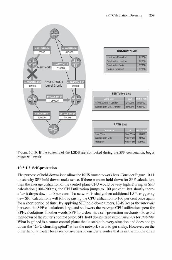
SPF Calculation Diversity 259
10.3.1.2 Self-protection
The purpose of hold-downs is to allow the IS-IS router to work less. Consider Figure 10.11to see why SPF hold downs make sense. If there were no hold-down for SPF calculation,then the average utilization of the control plane CPU would be very high. During an SPFcalculation (100–200 ms) the CPU utilization jumps to 100 per cent. But shortly there-after it drops down to 0 per cent. If a network is shaky, then additional LSPs triggeringnew SPF calculations will follow, raising the CPU utilization to 100 per cent once againfor a short period of time. By applying SPF hold-down timers, IS-IS keeps the intervalsbetween the SPF calculations large and so lowers the average CPU utilization spent forSPF calculations. In other words, SPF hold-down is a self-protection mechanism to avoidmeltdown of the router’s control plane. SPF hold downs trade responsiveness for stability.What is gained is a router control plane that is stable in every situation and does not godown the “CPU churning spiral” when the network starts to get shaky. However, on theother hand, a router loses responsiveness. Consider a router that is in the middle of an
87000600000
250000
22000 22000
315000
31500026000
London-�Frankfurt 22000
Frankfurt-�London 22000
Frankfurt-�Paris 87000
Paris-�Frankfurt 87000
LSDB entry cost
315000Pennsauken-�London 315000
Washington D.C.-�Paris 600000 648000
26000
via
Washington D.C 48000
298000
Pennsauken
oc192/STM-64 oc48/STM-16
New York
New Yorkoc48/STM-16
London
oc768/STM-256 Area 49.0001Level 2-only
oc768/STM-256
Washington
oc192/STM-64Frankfurt
oc12/STM-4 oc192/STM-64
Paris
UNKNOWN List
TENTative List
cost to root
Destination
New York New York
New York
New York
cost to root
Frankfurt
PATH List
FIGURE 10.10. If the contents of the LSDB are not locked during the SPF computation, bogusroutes will result

260
aver
age
uti
lizat
ion
1520
25t (
s)0
5s
hold
dow
n
2040100
CP
U lo
ad [%
]
5s
hold
dow
n5
s ho
ld d
own
5s
hold
dow
n5
s ho
ld d
own
6080
510
Peak utilization
Peak utilization
Peak utilization
Peak utilization
Peak utilization
Peak utilization
FIG
UR
E10
.11.
SPF
hold
-dow
ns s
moo
th th
e C
PU u
tiliz
atio
n

SPF hold-down period: even if plenty of LSPs do rush in, the router has to wait until thehold down period is over before scheduling the SPF calculation again. Then there areconsiderations like “How short should the hold-down time be to still be responsive?” and“How long should the hold-timer be to be stable enough?” and even “What is the optimalhold-down timer value?”
Unfortunately there is no universal hold-down timer value that applies to all networkingscenarios. Hold-down timers are always a compromise between stability and responsive-ness. Look at stability to start with: this mostly depends on network size and link stabil-ity. Network engineers used to say “In a quiet environment, OSPF and IS-IS are quietprotocols”.
In the infancy of link-state routing protocols there was usually a static SPF hold-downtimer of 5 seconds between SPF runs. This was a conservative timer, the better to scalefor large networks. Today, adaptive timers, which take into account the churn in the network,are more common. The basic idea behind the new schemes is that the first couple of SPFcalculations are scheduled immediately without any notable delay and only subsequent,persistent SPF runs are delayed. The more SPF runs need to be scheduled, the longer thehold-down timer gets. Such schemes are a much better compromise between responsivenessand stability than static timers can ever be.
The typical adaptive timer algorithm implementation reacts very fast, and is veryresponsive at first. This covers 99 per cent of the typical network-changing events, whichare link failures. That means that two LSPs arrive within a very short window. For theremaining 1 per cent of failure scenarios, the algorithm falls back to the older SPF hold-down static intervals for self-protection reasons.
JUNOS and IOS have different ways of implementing hold-down timers. IOS imple-ments a technique called exponential back off. Here the hold-down interval gets doubledeach time an SPF calculation is executed. The initial delay, the max-delay and the mini-mum hold-down interval can be configured using the using the spf-interval<max-holddown> [<initial-wait> <minimum-holddown>] configura-tion command. The following shows a custom configuration of the SPF hold downbehaviour in IOS. This works as follows:
IOS configurationIn IOS there are three timers to control SPF hold-down. The first timer specifies the SPFhold-down in the slower phase expressed in units of seconds. The second timer specifieshow many milliseconds to wait before scheduling the very first SPF calculation. The thirdtimer specifies the minimum SPF hold-down in the fast phase. The last two timers areexpressed in units of milliseconds.
London# show running-config
[ … ]
router isis
spf-interval 5 200 1000
[ … ]
SPF Calculation Diversity 261
Figure 10.12 shows the timing behaviour of the exponential back-off algorithm comparedto the JUNOS style, called a “3 � fast back-off” method. In IOS, the first SPF run isdelayed for 200 ms. Next, the minimum-hold-down timer kicks in, so scheduling of thesecond SPF run will take at least 1000 ms as specified in the third argument of the spf-interval configuration command. All subsequent SPF runs will get delayed for doublethe previous hold-down time, 2 seconds for the third SPF run, 4 seconds for the fourthSPF run, and so on. Similarly, the LSP origination interval, which was explained inChapter 6, “Generating, Flooding and Ageing LSPs”, also has a precaution that the hold-down does not grow to infinite value. Clipping of the hold-down timer is done with thefirst argument (5 seconds) of the spf-interval command. During every fast-build,the SPF interval gets bigger until it hits the ceiling of 5 seconds. After a particular routerhas not scheduled an SPF run for 20 seconds, the SPF hold-down state will be reset. Thismeans that from here on, any further SPF calculations will be scheduled “fast”, like thefirst couple of SPF runs.
JUNOS takes a different approach. Instead of gradually getting slower, there is a fixednumber of fast runs, and after that the router falls back into slow scheduling mode. Theengineers at Juniper Networks argue that this linear form of back off has worked fine forthe past 10 years, and more sophisticated methods are not needed. In most implementations,the static SPF hold-down period is set to 5 seconds and by straight switching between thetwo modes, fast and slow, no harm is done.
JUNOS has an initial pre-SPF timer that defaults to 200 ms. It can be changed usingthe spf-delay configuration command, which is available under the protocolsisis stanza. This command affects both the partial and the full SPF calculation and canbe changed in the range from 50 ms to 1000 ms.
JUNOS configurationIn JUNOS there is only one timer that controls SPF scheduling. The spf-interval con-figuration command determines in units of milliseconds the initial-wait and inter-SPF waitperiod when scheduling SPF calculations.
hannes@Vienna> show configuration
[ … ]
protocols {
isis {
spf-delay 100;
interface lo0.0;
interface so-0/0/0;
}
}
All other values are hard coded into JUNOS. The number of fast runs is 3 and the min-imum pre-SPF timer can go as low as 50 ms. In the above configuration example, therouter has to wait 100 ms before an SPF calculation is scheduled, and 100 ms betweenSPF calculations.
262 10. SPF and Route Calculation

263
2000
4000
6000
8000
1000
012
000
027
000
5000
ms
hold
dow
n (m
ax h
old
dow
n)
Afte
r 20
s fa
llbac
k to
fast
beh
avio
ur
IOS
exp
on
enti
al h
old
-do
wn
beh
avio
ur
2000
4000
6000
8000
1000
012
000
024
000
Afte
r 20
s fa
llbac
k to
fast
beh
avio
ur
JUN
OS
(3x
sh
ort
, aft
er t
hat
lon
g)
ho
ld-d
ow
n b
ehav
iou
r
Firs
tLS
Prc
vd
Sec
ond
LSP
rcvd
Firs
tS
PF
run
Sec
ond
SP
Fru
n
Thi
rdLS
Prc
vd Thi
rdS
PF
run
Fou
rth
LSP
rcvd Fou
rth
SP
Fru
n
1000
ms
hold
dow
n20
00m
sho
ld d
own
4000
ms
hold
dow
nt (
ms)
t (m
s)
Firs
tLS
Prc
vd
Sec
ond
LSP
rcvd
Thi
rdLS
Prc
vd
Firs
tS
PF
run
Sec
ond
SP
Fru
n
Thi
rdS
PF
run
1000
ms
hold
dow
n10
00m
sho
ld d
own
1000
ms
hold
dow
n50
00m
sho
ld d
own
(max
hol
d do
wn)
FIG
UR
E10
.12.
IOS
mak
es th
e ho
ld-d
own
inte
rval
exp
onen
tially
long
er –
JU
NO
S st
arts
with
thre
e sh
ort a
nd a
fter
that
use
s lo
ng h
old-
dow
n in
terv
als

10.3.1.3 Timer Compatibility Issues
It is recommended to keep at least the initial-wait timer the same across the IOS andJUNOS routers in a network. Once they are the same it is certain that the SPF calculationsstart and finish almost simultaneously. Due to the hop-by-hop routing paradigm, nearsimultaneous SPF calculations and re-routing is desired to avoid transient loops. However,it can never be guaranteed that two routers converge at the same time, but keeping thetimers current is usually good enough, or at least does not break the desired global conver-gence intentionally.
The following two IOS and JUNOS configuration files are a good tradeoff between thetwo schemes and have proven to work well even in large multi-vendor networks.
JUNOS configurationAn SPF delay of 100 ms means that the SPF algorithm converges fast and still providesreasonable protection. The typical SPF run in large networks does not last longer than100 ms. This 100 ms of quiet takes the average utilization down to 50 per cent.
hannes@Vienna> show configuration
[… ]
protocols {
isis {
spf-delay 100;
interface lo0.0;
interface so-0/0/0;
}
}
IOS configurationThe two 100 ms arguments make the initial-wait and minimum hold-down behaviourexactly like JUNOS. The first argument specifies the maximum SPF hold-down value,which is hard-coded in JUNOS as well.
London# show running-config
[ … ]
router isis
spf-interval 5 100 100
[ … ]
10.3.1.4 Performance and CPU Usage
The CPU cost of a plain, un-optimized SPF run is probably one of the most well-examinedalgorithms in computer science. Before assessing worst-case figures, first consider twofactors: how many routers and how many links are in the network. Let the number ofrouters be N and the number of links be L.
264 10. SPF and Route Calculation

SPF Calculation Diversity 265
It is actually very hard to predict the SPF runtime, as it is highly dependent on thetopology, that is, how the routers are meshed to each other. It has been shown above thatthe tracking of nodes on the PATH list consumes the most cycles. So what is done is topresent a worst-case and an average-case scenario, considering the number of routers (N)or the number of links (L). To find out what the real SPF runtime will be, and it will besomewhere between the two figures, how densely meshed the network is has to be takeninto account.
For a router-based, worst case estimate, simply take a look at the number of routersand the number of search operations, assuming that every router is in the worst case con-nected to every other router (a full mesh). Therefore, for a total of N nodes, at maximumN–1 iterations steps are needed for the search operation to find out if the actual path isbetter than the TENTative path. This is quite intuitive. Mathematically speaking, the runtimerequirements of the SPF run equals N * N–1 or O(N^2). Squared growth is really, reallythe worst case.
Exploring all the feasible path scales directly, along with the absolute number of linksit can be shown that the SPF computation time is proportional to the number of links inthe network. Mathematically speaking, O(L * log(L)).
For example, let the number of routers be 100 and the numbers of links be 400. Thenthe worst-case estimate would be that O(N^2) CPU-time-units (100 * 100 � 10000) arespent. The abstract unit “CPU-time units” is used because such observations only makesense in a comparative way. If there is a given number of nodes and a given number oflinks in a network, and the current SPF run time, a good estimate of the CPU runtime inthe future, when the number of routers and the number of links is higher, can be made.The pure link-based observation results in a computational complexity of L * log(L),which is 400 * (log(400)) � 1040 of CPU time-units.
So there is a factor of 10 deviation between the two estimates. In reality both the numberof links and the number of routers need to be considered. Both figures are needed for themeshing factor, that is, how densely a given set of routers is meshed. It will be shownshortly that the link-based model is a much better approximation than the worst-caseestimate.
The model where the total SPF runtime equals N (log(N)*2*log(L)) turns out to workbest in practice. In this formula, both the number of links and the number of nodes plusa factor of two go into the formula. The factor of two is needed because the two-waycheck is part of the path selection algorithm. Based on that formula, the resulting calcula-tions come very close to reality. See Table 10.1 for the best model of route-processorCPU prediction around today.
The theoretical model was verified using a lab test based on two common routeprocessors: the Juniper Networks RE 3.0 taken from the M & T-Series of Routers, andthe GRP Routing Engine taking from the Cisco GSR 12000 series. The two route processorswere exercised using the Agilent QA Robot Router Control-Plane Stress Testing Software.The Router Tester produces a grid, as shown in Figure 10.13.
Every 25 seconds, one link of the virtual topology was changed and the SPF runtimeshave been recorded using the show isis spf-log operational level CLI commandon IOS and show isis spf log on JUNOS.

IOS command outputLondon#show isis spf-log
Level 1 SPF log
When Duration Nodes Count Last trigger LSP Triggers
04:17:46 0.021189 408 1 virtual-5-3.00-00 DELADJ
TLVCODE
04:15:46 0.021224 408 1 PERIODIC
04:00:46 0.021712 408 1 PERIODIC
03:45:46 0.021323 408 1 PERIODIC
[ … ]
JUNOS command outputhannes@Frankfurt> show isis spf log
IS-IS level 1 SPF log:
Start time Elapsed (secs) Count Reason
Sat Nov 1 15:04:34 0.017179 1 Periodic SPF
Sat Nov 1 15:19:03 0.017067 1 Periodic PF
Sat Nov 1 15:31:47 0.017081 1 Periodic SPF
Sat Nov 1 15:44:19 0.017334 1 Periodic SPF
[ … ]
Sat Nov 1 15:45:07 0.017365 1 Updated LSP
[ … ] virtual-5-3.00-00
Both outputs show the reason (trigger) and the duration of the SPF calculation.The disparity between the theoretical prediction model and the simulation on the virtual
topology has been less than 3 per cent. Therefore, the model gives a good prediction of howlong the full SPF run will last in practice. The result of the simulation and the prediction
266 10. SPF and Route Calculation
TABLE 10.1. A prediction of real-world SPF runtime on common control plane CPUs.Routers Links SPF runtime (ms) Juniper SPF runtime (ms) Cisco
Networks Routing Engine 3.0 Systems GRP 12000
100 250 1,92 4,80200 500 4,97 12,42400 1000 12,49 31,22600 1500 21,18 52,94800 2000 30,67 76,671000 2500 40,78 101,941500 3750 68,11 170,272000 5000 97,68 244,212500 6250 128,98 322,453000 7500 161,69 404,224000 10000 230,53 576,335000 12500 303,09 757,726000 15000 378,67 946,677000 17500 456,82 1142,048000 20000 537,19 1342,989000 22500 619,55 1548,8610000 25000 703,67 1759,18
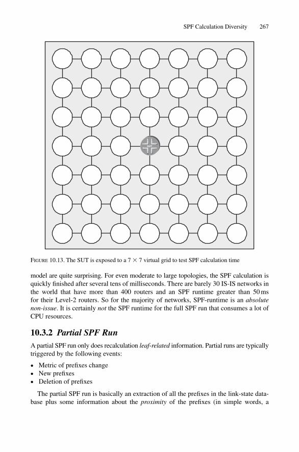
model are quite surprising. For even moderate to large topologies, the SPF calculation isquickly finished after several tens of milliseconds. There are barely 30 IS-IS networks inthe world that have more than 400 routers and an SPF runtime greater than 50 ms for their Level-2 routers. So for the majority of networks, SPF-runtime is an absolutenon-issue. It is certainly not the SPF runtime for the full SPF run that consumes a lot ofCPU resources.
10.3.2 Partial SPF RunA partial SPF run only does recalculation leaf-related information. Partial runs are typicallytriggered by the following events:
• Metric of prefixes change• New prefixes• Deletion of prefixes
The partial SPF run is basically an extraction of all the prefixes in the link-state data-base plus some information about the proximity of the prefixes (in simple words, a
SPF Calculation Diversity 267
SUT
FIGURE 10.13. The SUT is exposed to a 7 � 7 virtual grid to test SPF calculation time
metric). Based on that, the partial run is basically a search operation, which tries to findout the lowest metric for a given prefix. Figure 10.14 illustrates the simplicity of a partialSPF calculation. All the leaf information from the routers on the PATH list, plus thePennsauken root router, extract their IPv4 prefixes and move them to a table. Next, thelist is sorted and duplicate entries with a worse cost are eliminated. Finally, the prefixesare sorted by their cost in ascending order. This simple search operation is computationallymuch less complex than the topological section of the full SPF run.
Both JUNOS and IOS support partial runs for IPv4 and IPv6. In IOS, you can alsocontrol the SPF delay for partial route calculations (PRCs). PRC is an IOS term and canbe controlled using the prc-interval router isis configuration command. Thesetimers can be more aggressive (shorter) than the spf-interval <a> <b> <c>timers. This is because the burden that a partial SPF run adds to a control plane is not ashigh as a full run, so the router does not need to self-protect so much. The following con-figuration example sets the router pre-SPF timer (initial wait) before doing a partial SPFcalculation to 100 ms. For the second run, the router holds down for 250 ms. The PRCalso employs an exponential back-off timer. That means after the second run, the hold-down value is now 500 ms. The first argument of the command controls the maximumhold-down value of one second.
IOS configurationIn IOS there are three timers to control partial SPF hold down. The three timers work sim-ilarly to the timers for the spf-interval configuration command.
London# show running-config
[ … ]
router isis
prc-interval 1 100 250
[ … ]
JUNOS does not have a dedicated control knob to control the PRC behaviour. InJUNOS, there is just one hold-down logic path. For partial SPF runs, therefore, the samehold-down logic applies as for full SPF runs. it is recommended setting the three IOSparameters 5, 200 and 200 for compatiblity to the JUNOS default behaviour.
10.3.2.1 Performance and CPU Usage
Partial SPF runs are pretty cheap from the calculation point of view. A router has to scanthrough all the routers in its link-state database, extract the prefix information, add theprefix cost of the distance to the originating router, and sort the prefixes to find out whichis closest. This exhibits absolutely linear behaviour, meaning the CPU processing time isdirectly proportional to the number of routes in the network. Mathematically speaking,this would be O(R) with R being the number of prefixes of an address family. In practicalimplementations, the cost of the partial SPF run nears zero cost. Typically, the partial runis less than 10 ms execution time, even if R is unreasonably high (like 10,000) routes. Sopartial runs are even less of an issue than full SPF runs.
268 10. SPF and Route Calculation

269
172.16.33.16/30
172.16.33.0/30
172.16.33.12/30
172.16.33.4/30
172.16.33.28/30
172.16.33.24/30
172.16.33.8/30
SP
F R
esu
lt li
st
via
cost
Ext
ract
ed IP
v4 P
refi
x lis
t
New
Yor
k26
000
Was
hing
ton
4800
0
Fra
nkfu
rt29
8000
Lond
on
Par
is
3150
00
3850
00
Des
tin
atio
no
rig
inco
st
Pen
nsau
ken
-0
192.
168.
0.19
/32
172.
16.3
3.0/
3017
2.16
.33.
16/3
0
192.
168.
0.8/
3217
2.16
.33.
8/30
172.
16.3
3.12
/30
172.
16.3
3.20
/30
172.
16.3
3.24
/30
192.
168.
0.12
/32
172.
16.3
3.4/
3017
2.16
.33.
12/3
0
So
rted
IPv4
pre
fix
list
Des
tin
atio
nco
st19
2.16
8.0.
17/3
20
172.
16.3
3.0/
300
172.
16.3
3.4/
300
192.
168.
0.19
/32
172.
16.3
3.16
/30
2600
0
172.
16.3
3.8/
300
192.
168.
0.21
/32
4800
017
2.16
.33.
20/3
017
2.16
.33.
28/3
019
2.16
8.0.
8/32
2980
0017
2.16
.33.
24/3
029
8000
192.
168.
0.12
/32
3150
0017
2.16
.33.
12/3
031
5000
192.
168.
0.22
/32
3850
0017
2.16
.33.
24/3
038
5000
192.
168.
0.17
/32
017
2.16
.33.
0/30
017
2.16
.33.
4/30
017
2.16
.33.
8/30
0
192.
168.
0.21
/32
172.
16.3
3.16
/30
172.
16.3
3.20
/30
172.
16.3
3.28
/30
192.
168.
0.22
/32
172.
16.3
3.24
/30
172.
16.3
3.28
/30
Pen
nsa
uke
n
192.
168.
0.17
New
Yo
rk
192.
168.
0.19
Lo
nd
on
192.
168.
0.12
Was
hin
gto
n
192.
168.
0.21
172.
16.3
3.20
/30
Fra
nkf
urt
192.
168.
0.8
Par
is
192.
168.
0.22
Des
tin
atio
n
New
Yor
k
New
Yor
k
New
Yor
k
New
Yor
k
Lond
on
Was
hing
ton
Was
hing
ton
Was
hing
ton
Was
hing
ton
New
Yor
kN
ew Y
ork
New
Yor
kP
aris
Par
isP
aris
Pen
nsau
ken
Pen
nsau
ken
Pen
nsau
ken
Pen
nsau
ken
Fra
nkfu
rtF
rank
furt
Fra
nkfu
rtF
rank
furt
Fra
nkfu
rtLo
ndon
Lond
onLo
ndon
4800
048
000
4800
048
000
2600
026
000
2600
038
5000
3850
0038
5000
2980
0029
8000
2980
0029
8000
2980
0031
5000
3150
0031
5000
Par
tial S
PF
calc
ulat
ion
ori
gin
Pen
nsau
ken
Pen
nsau
ken
Pen
nsau
ken
Pen
nsau
ken
New
Yor
kN
ew Y
ork
Was
hing
ton
Was
hing
ton
Was
hing
ton
Fra
nkfu
rtF
rank
furt
Lond
onLo
ndon
Par
isP
aris
2600
0
4800
048
000
FIG
UR
E10
.14.
A p
artia
l rou
te c
alcu
latio
n (P
RC
) is
bas
ical
ly a
sim
ple,
com
puta
tiona
l che
ap s
ort o
pera
tion
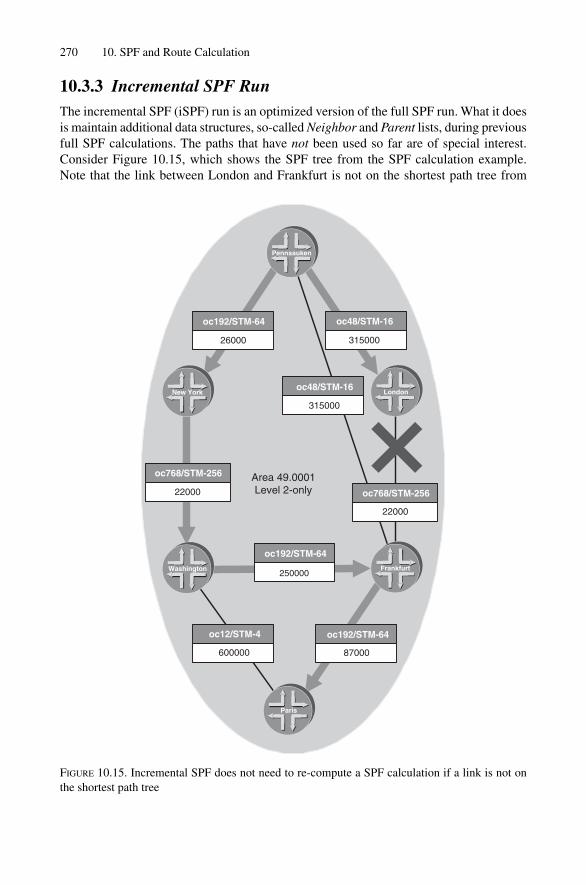
10.3.3 Incremental SPF RunThe incremental SPF (iSPF) run is an optimized version of the full SPF run. What it doesis maintain additional data structures, so-called Neighbor and Parent lists, during previousfull SPF calculations. The paths that have not been used so far are of special interest.Consider Figure 10.15, which shows the SPF tree from the SPF calculation example.Note that the link between London and Frankfurt is not on the shortest path tree from
270 10. SPF and Route Calculation
Pennsauken
Paris
oc192/STM-64
26000
New York
oc768/STM-256
22000
Washington
oc12/STM-4
600000
oc192/STM-64
87000
250000
oc192/STM-64
Area 49.0001Level 2-only
Frankfurt
oc768/STM-256
22000
Londonoc48/STM-16
315000
oc48/STM-16
315000
FIGURE 10.15. Incremental SPF does not need to re-compute a SPF calculation if a link is not onthe shortest path tree
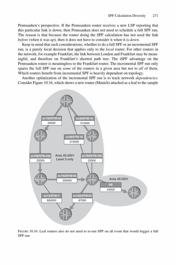
Pennsauken’s perspective. If the Pennsauken router receives a new LSP reporting thatthis particular link is down, then Pennsauken does not need to schedule a full SPF run.The reason is that because the router doing the SPF calculation has not used the linkbefore (when it was up), then it does not have to consider it when it is down.
Keep in mind that such considerations, whether to do a full SPF or an incremental SPFrun, is a purely local decision that applies only to the local router. For other routers in the network, for example Frankfurt, the link between London and Frankfurt may be mean-ingful, and therefore on Frankfurt’s shortest path tree. The iSPF advantage on thePennsauken router is meaningless to the Frankfurt router. The incremental SPF run onlyspares the full SPF run on some of the routers in a given area but not to all of them.Which routers benefit from incremental SPF is heavily dependent on topology.
Another optimization of the incremental SPF run is to track network dependencies.Consider Figure 10.16, which shows a new router (Munich) attached as a leaf to the sample
SPF Calculation Diversity 271
87000600000
250000
22000 22000
oc48/STM-16
315000
31500026000
43000
GE
Pennsauken
oc192/STM-64 oc48/STM-16
LondonNew York
oc768/STM-256 Area 49.0001Level 2-only
oc768/STM-256
Washington
oc192/STM-64
oc12/STM-4 oc192/STM-64
Frankfurt
Paris
Area 49.0001
Munich
FIGURE 10.16. Leaf routers also do not need to re-run SPF on all event that would trigger a fullSPF run
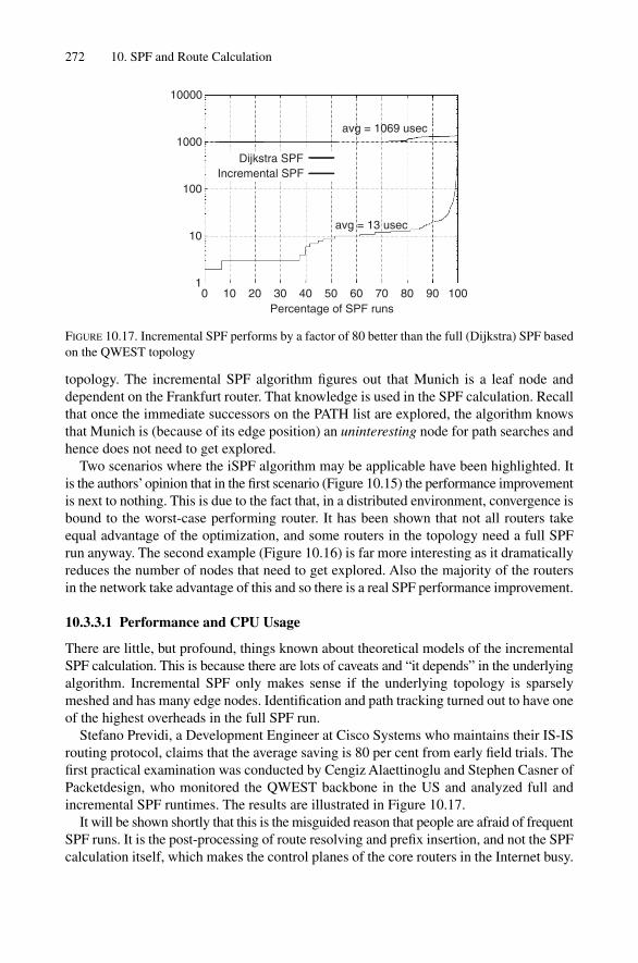
topology. The incremental SPF algorithm figures out that Munich is a leaf node anddependent on the Frankfurt router. That knowledge is used in the SPF calculation. Recallthat once the immediate successors on the PATH list are explored, the algorithm knowsthat Munich is (because of its edge position) an uninteresting node for path searches andhence does not need to get explored.
Two scenarios where the iSPF algorithm may be applicable have been highlighted. Itis the authors’opinion that in the first scenario (Figure 10.15) the performance improvementis next to nothing. This is due to the fact that, in a distributed environment, convergence isbound to the worst-case performing router. It has been shown that not all routers takeequal advantage of the optimization, and some routers in the topology need a full SPFrun anyway. The second example (Figure 10.16) is far more interesting as it dramaticallyreduces the number of nodes that need to get explored. Also the majority of the routersin the network take advantage of this and so there is a real SPF performance improvement.
10.3.3.1 Performance and CPU Usage
There are little, but profound, things known about theoretical models of the incrementalSPF calculation. This is because there are lots of caveats and “it depends” in the underlyingalgorithm. Incremental SPF only makes sense if the underlying topology is sparselymeshed and has many edge nodes. Identification and path tracking turned out to have oneof the highest overheads in the full SPF run.
Stefano Previdi, a Development Engineer at Cisco Systems who maintains their IS-ISrouting protocol, claims that the average saving is 80 per cent from early field trials. Thefirst practical examination was conducted by Cengiz Alaettinoglu and Stephen Casner ofPacketdesign, who monitored the QWEST backbone in the US and analyzed full andincremental SPF runtimes. The results are illustrated in Figure 10.17.
It will be shown shortly that this is the misguided reason that people are afraid of frequentSPF runs. It is the post-processing of route resolving and prefix insertion, and not the SPFcalculation itself, which makes the control planes of the core routers in the Internet busy.
272 10. SPF and Route Calculation
10000
1000
100
10
10 10 20 30 40 50 60 70 80 90 100
Percentage of SPF runs
avg = 13 usec
Dijkstra SPFIncremental SPF
avg = 1069 usec
FIGURE 10.17. Incremental SPF performs by a factor of 80 better than the full (Dijkstra) SPF basedon the QWEST topology
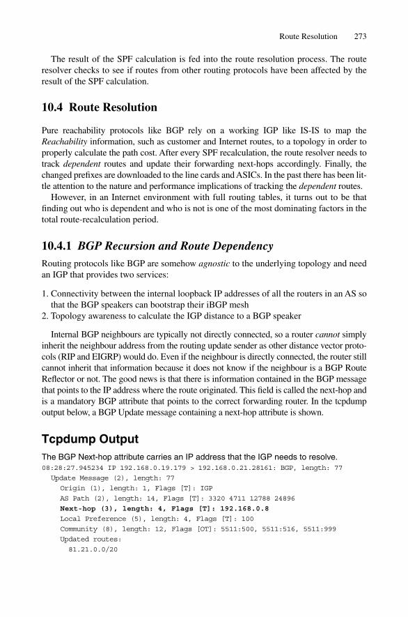
The result of the SPF calculation is fed into the route resolution process. The routeresolver checks to see if routes from other routing protocols have been affected by theresult of the SPF calculation.
10.4 Route Resolution
Pure reachability protocols like BGP rely on a working IGP like IS-IS to map theReachability information, such as customer and Internet routes, to a topology in order toproperly calculate the path cost. After every SPF recalculation, the route resolver needs totrack dependent routes and update their forwarding next-hops accordingly. Finally, thechanged prefixes are downloaded to the line cards and ASICs. In the past there has been lit-tle attention to the nature and performance implications of tracking the dependent routes.
However, in an Internet environment with full routing tables, it turns out to be thatfinding out who is dependent and who is not is one of the most dominating factors in thetotal route-recalculation period.
10.4.1 BGP Recursion and Route DependencyRouting protocols like BGP are somehow agnostic to the underlying topology and needan IGP that provides two services:
1. Connectivity between the internal loopback IP addresses of all the routers in an AS sothat the BGP speakers can bootstrap their iBGP mesh
2. Topology awareness to calculate the IGP distance to a BGP speaker
Internal BGP neighbours are typically not directly connected, so a router cannot simplyinherit the neighbour address from the routing update sender as other distance vector proto-cols (RIP and EIGRP) would do. Even if the neighbour is directly connected, the router stillcannot inherit that information because it does not know if the neighbour is a BGP RouteReflector or not. The good news is that there is information contained in the BGP messagethat points to the IP address where the route originated. This field is called the next-hop andis a mandatory BGP attribute that points to the correct forwarding router. In the tcpdumpoutput below, a BGP Update message containing a next-hop attribute is shown.
Tcpdump OutputThe BGP Next-hop attribute carries an IP address that the IGP needs to resolve.08:28:27.945234 IP 192.168.0.19.179 > 192.168.0.21.28161: BGP, length: 77
Update Message (2), length: 77
Origin (1), length: 1, Flags [T]: IGP
AS Path (2), length: 14, Flags [T]: 3320 4711 12788 24896
Next-hop (3), length: 4, Flags [T]: 192.168.0.8
Local Preference (5), length: 4, Flags [T]: 100
Community (8), length: 12, Flags [OT]: 5511:500, 5511:516, 5511:999
Updated routes:
81.21.0.0/20
Route Resolution 273
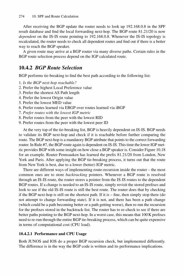
After receiving the BGP update the router needs to look up 192.168.0.8 in the SPFresult database and find the local forwarding next-hop. The BGP route 81.21/20 is nowdependent on the IS-IS route pointing to 192.168.0.8. Whenever the IS-IS topology isrecalculated, the router needs to check all dependent routes and find out if there is a betterway to reach the BGP speaker.
A given route may arrive at a BGP router via many diverse paths. Certain rules in theBGP route selection process depend on the IGP calculated route.
10.4.2 BGP Route SelectionBGP performs tie-breaking to find the best path according to the following list:
1. Is the BGP next-hop reachable?2. Prefer the highest Local Preference value3. Prefer the shortest AS Path length4. Prefer the lowest Origin value5. Prefer the lowest MED value6. Prefer routes learned via EBGP over routes learned via iBGP7. Prefer routes with the lowest IGP metric8. Prefer routes from the peer with the lowest RID9. Prefer routes from the peer with the lowest peer ID
At the very top of the tie-breaking list, BGP is heavily dependent on IS-IS. BGP needsto validate its BGP next-hop and check if it is reachable before further comparing theroute. The BGP next-hop is a mandatory BGP attribute that points to the correct forwardingrouter. In Rule #7, the BGP route again is dependent on IS-IS. This time the lower IGP met-ric provides BGP with some insight on how close a BGP speaker is. Consider Figure 10.18for an example. Router Pennsauken has learned the prefix 81.21/20 from London, NewYork and Paris. After applying the BGP tie-breaking process, it turns out that the routefrom New York is best, due to a lower (better) IGP metric.
There are different ways of implementing route-recursion inside the router – the mostcommon ones are to store backtracking pointers. Whenever a BGP route is resolvedthrough an IS-IS route, the router stores a pointer from the IS-IS routes to the dependentBGP routes. If a change is needed to an IS-IS route, simply revisit the stored prefixes andlook to see if the old IS-IS route is still the best route. The router does that by checkingif the BGP next-hop is still on the shortest path. If it is – fine, then simply stop there (donot attempt to change forwarding state). If it is not, and there has been a path change(which could be a path becoming better or a path getting worse), then re-run the recursionfor the prefixes stored in the backtrack-list. The router has to re-check to see if there arebetter paths pointing to the BGP next-hop. In a worst case, this means that 100 K prefixesneed to re-run through the entire BGP tie-breaking process, which can be quite expensivein terms of computational cost (CPU load).
10.4.2.1 Performance and CPU Usage
Both JUNOS and IOS do a proper BGP recursion check, but implemented differently.The difference is in the way the BGP code is written and its performance implications.
274 10. SPF and Route Calculation

In IOS the BGP code is job-based. That means whenever there is a change to a BGPlearned prefix only a flag in the data-structure of the prefix is set or cleared. Then thereis a job that scans the BGP table for changed entries (called the BGP walker). Why is thisinformation relevant for a book about IS-IS? It means that even if IS-IS has detected thata link has been broken, and must perform all the relevant actions (flooding, scheduling ofan SPF full run etc.), it takes in the worst case the BGP walker duration in IOS (50 sec-onds) until the Cisco router starts to change prefixes, update forwarding states, and so on.So the implementation style of the BGP implementation dictates the convergence behaviourof the BGP routes. Perhaps this is not the best design choice. In all fairness, the firstimplementation of BGP in IOS was coded at a time when the Internet consisted of noteven 1000 routes. So it is probably not bad design, but a legacy effect.
In contrast, JUNOS routing software is event-driven. That means that whenever a sub-system in the router notices that something has gone wrong, or is up again, that changeis propagated throughout the system immediately and without any delay. Immediatelyafter the SPF run, JUNOS does BGP recursion.
Both implementations result in a list of prefixes that need to change in the main routingtable. After that, the router updates the forwarding state in the forwarding plane. Updatingthe forwarding plane is the most daunting task of all because it makes both the forwardingand control plane CPUs really busy. The reason this keeps both CPUs busy is the sheeramount of data and table sizes that has to be pumped through a router’s chassis. Currently
Route Resolution 275
Area 49.0001Level 2-only
oc192/STM-64
87000
oc12/STM-4
600000
oc192/STM-64
250000
oc768/STM-256
22000
oc768/STM-256
22000
oc48/STM-16
315000
oc48/STM-16
315000
oc192/STM-64
26000
Origin: IGPAS Path: 5511 2874 12788 24896Next-hop: 192.168.0.12Local preference: 100
81.21.0.0/20Origin: IGPAS Path: 701 702 12788 24896Next-hop: 192.168.0.19Local preference: 100
81.21.0.0/20
Origin: IGPAS Path: 3320 8847 12788 24896Next-hop: 192.168.0.8Local preference: 100Community: 3320:4711
81.21.0.0/20
LondonNew york
Pennsauken
New York
Paris
Community: 5511:500, 5511:516, 5511:999
Washington Frankfurt
London
FIGURE 10.18. The transit route 81.21/20 via Pennsauken wins the BGP tie-breaking process
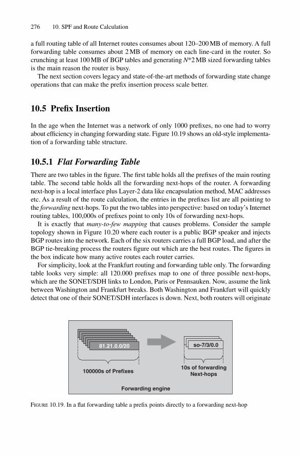
a full routing table of all Internet routes consumes about 120–200 MB of memory. A fullforwarding table consumes about 2 MB of memory on each line-card in the router. Socrunching at least 100 MB of BGP tables and generating N*2 MB sized forwarding tablesis the main reason the router is busy.
The next section covers legacy and state-of-the-art methods of forwarding state changeoperations that can make the prefix insertion process scale better.
10.5 Prefix Insertion
In the age when the Internet was a network of only 1000 prefixes, no one had to worryabout efficiency in changing forwarding state. Figure 10.19 shows an old-style implementa-tion of a forwarding table structure.
10.5.1 Flat Forwarding TableThere are two tables in the figure. The first table holds all the prefixes of the main routingtable. The second table holds all the forwarding next-hops of the router. A forwardingnext-hop is a local interface plus Layer-2 data like encapsulation method, MAC addressesetc. As a result of the route calculation, the entries in the prefixes list are all pointing tothe forwarding next-hops. To put the two tables into perspective: based on today’s Internetrouting tables, 100,000s of prefixes point to only 10s of forwarding next-hops.
It is exactly that many-to-few mapping that causes problems. Consider the sampletopology shown in Figure 10.20 where each router is a public BGP speaker and injectsBGP routes into the network. Each of the six routers carries a full BGP load, and after theBGP tie-breaking process the routers figure out which are the best routes. The figures inthe box indicate how many active routes each router carries.
For simplicity, look at the Frankfurt routing and forwarding table only. The forwardingtable looks very simple: all 120.000 prefixes map to one of three possible next-hops,which are the SONET/SDH links to London, Paris or Pennsauken. Now, assume the linkbetween Washington and Frankfurt breaks. Both Washington and Frankfurt will quicklydetect that one of their SONET/SDH interfaces is down. Next, both routers will originate
276 10. SPF and Route Calculation
Forwarding engine
81.21.0.0/20 so-7/3/0.0
100000s of Prefixes10s of forwarding
Next-hops
FIGURE 10.19. In a flat forwarding table a prefix points directly to a forwarding next-hop

a new LSP declaring the adjacency down. Because of the default values of the SPF hold-down timers in the network, the SPF run will be scheduled after 100 ms. As the numberof nodes and links is low, in less than one millisecond the results will be available. Nowthe scary part begins: the recursion and change of forwarding state in the forwardingplane. The routing tables are traversed in 1–2 seconds and the control plane realizes thatit has to change 40,000 prefixes. The route processor computes new forwarding tablesand loads them down to the line-cards. Because of the fact that the router has to update
Prefix Insertion 277
Area 49.0001Level 2-only
LondonNew York
BGP
13K activeroutes
Pennsauken
Frankfurt
London
Washington
New York
Paris
BGP
40K activeroutes
BGP
18K activeroutes
BGP
17K activeroutes
BGP
22K activeroutes
BGP
10K activeroutes
FIGURE 10.20. Each router in the sample topology is a BGP router and carries several thousandactive paths

40 K prefixes, the total convergence time until the last prefix is updated takes about40 seconds (if not minutes) depending on the router hardware. Updating forwardingtables under load is hard and quite expensive to achieve.
10.5.2 Hierarchical Forwarding TableThe alternate solution does not map the prefixes directly to the forwarding next-hops.There is instead the notion of an indirect next-hop. An indirect Next-hop is the originatorof a prefix that is not directly connected to the router. It is a different way of modellingthe dependency from BGP routes to IS-IS routes at a forwarding table level. Consider thesample network again, where there are six BGP speakers. Therefore the number of indirectnext-hops equals six. Figure 10.21 shows how the forwarding table is implemented. The120,000 prefixes do not point to the forwarding next-hop directly anymore, but rather totheir corresponding indirect next-hops. The indirect next-hops finally point to the forward-ing next-hop. This is the key point: 120.000 interfaces point to six indirect next-hops,which point to only three physical interfaces. What is gained from that, except anothermemory lookup in the forwarding path to find out the indirect next-hop? Actually, a lotis gained once it comes down to changing the fowarding state. Look at the previousexample where the link between Washington and Frankfurt fails and assume the forwardingtable is structured as in Figure 10.21. After LSP propagation, a full SPF run, and BGPrecursion some BGP speakers (most notably Washington) are found to have a differentpath. Previously the link outage traffic to Washington has been routed straight, but nowit is re-routed via Paris. The good news is that now at least 40.000 pointers that pointfrom the prefixes to the forwarding next-hops do not have to be changed. The only thingthat the router needs to do is flip one pointer!
The hierarchical scheme does trade some forwarding lookup latency (less than 1microsecond) against maintainability and convergence of the forwarding tables. However,given that there are multiservice networks deployed today transporting all kinds of traffic,convergence considerations are always important and need to be considered.
There is one case when the abstraction of indirect next-hops to next-hops does nothelp, which is the case when an indirect next-hop (a BGP speaker) goes down. Then BGPneeds to find out during the recursion run which BGP routes have to change their next-
278 10. SPF and Route Calculation
Forwarding engine
81.21.0.0/20 192.168.0.8 so-7/3/0.0
100s of BGP Next-hops100000s of Prefixes 10s of forwardingNext-hops
FIGURE 10.21. In a hierarchical forwarding table a prefix points first to an indirect next-hop, whichmaps finally to a forwarding next-hop

hop information and reassign these prefixes to other indirect next-hops. Ultimately thiswill result in a massive amount of forwarding state changes at the forwarding plane. Thespeed of the raw forwarding table changes at about 5000–6000 prefixes per second. Acommon design practice is (if possible) to balance the number of active BGP pathsevenly across a network by incorporating a good and solid peering mesh with other ASs.Reducing the number of active routes per-AS makes sure that if an indirect next-hop(BGP speaker) goes down, the re-routing is done within several seconds.
10.6 Conclusion
The CPU impact of the SPF algorithm really has been “demonized” in the past. Fears thatan SPF calculation may lock up a router entirely are not justified today. Modern controlplane processors have sufficient CPU power to recalculate even large topologies in thesub-second range, so the bare SPF algorithm itself is not the problem anymore. The associ-ated BGP recursion check can be completed in sub-second range as well. What persistsas a challenge is the final stage of the post-processing cycle of the SPF results. Forwardingtable maintenance in modern routers can fully engage the CPUs for several seconds,much more than SPF ever could do. This challenge can be tackled from two sides: on thevendor side, by applying clever implementation techniques like indirect Next-hops in theforwarding path and, on the service provider side, by doing a proper network design.With proper balancing of active BGP paths evenly across the network, a network carryingeven 120,000 routes converges in a both fast and stable manner.
Conclusion 279

11
TLVs and Sub-TLVs
Charles Darwin’s classic theory of evolution and its basic mechanism of natural selectionthrough mutation can be re-applied to technology and the Internet. As the environmentchanges, entities within the environment must change as well or become extinct. Indeed,the relationship between the evolution of living creatures and the evolution of Internettechnology is impressive. Each age of technology builds upon the discoveries of the pre-vious age resulting in a constant change, which also helps humankind to adapt to or copewith their technological environment. Experience from the last decade of networking hasshown that Darwin’s Law is just as present and active in networking as anywhere else inlife. When Darwin is translated to the routing protocols environment this means that notthe strongest, most lightweight or most optimal routing protocol, algorithm and imple-mentation at a fixed, given time will prevail in the end. The routing protocol that wins thetechnology prize for survival of the fittest will be the one that adapts best to its changingInternet environment and can add features mandated by passing time. Based on the his-torical development of the OSPF routing protocol, it will be shown why Darwin’s Law isvalid in the technology environment.
11.1 Taxonomy for Extensibility
First of all, the term extensibility as used in this chapter will be defined in more detail. In any discussion of extensibility, there are three things that need to be considered:
• How do current software maturation models work?• What are the ramifications if a routing protocol is barely or not extensible at all?• What does it mean when a routing protocol is called extensible?
Software quality assurance is still a young topic in computer science. This is especiallytrue for the additional complexity of distributed systems, where one failing node mayimpact others, no really clueful model has been found. Best common practice to ensuresoftware quality is hardening by deploying. This essentially means that if software isdeployed frequently, all the inherent bugs will finally go away after a maturation cycle. Inthe next paragraph, a typical software maturation cycle is described.
11.1.1 Current Software Maturation ModelsThe most common software maturation model applicable in the last decade is brieflydescribed in Figure 11.1 and explained as follows:
1. Develop the base (alpha) code. This is the first engineering cut at the program and willnot be released publicly. This software is tested at the router vendor’s internal test bed.
281
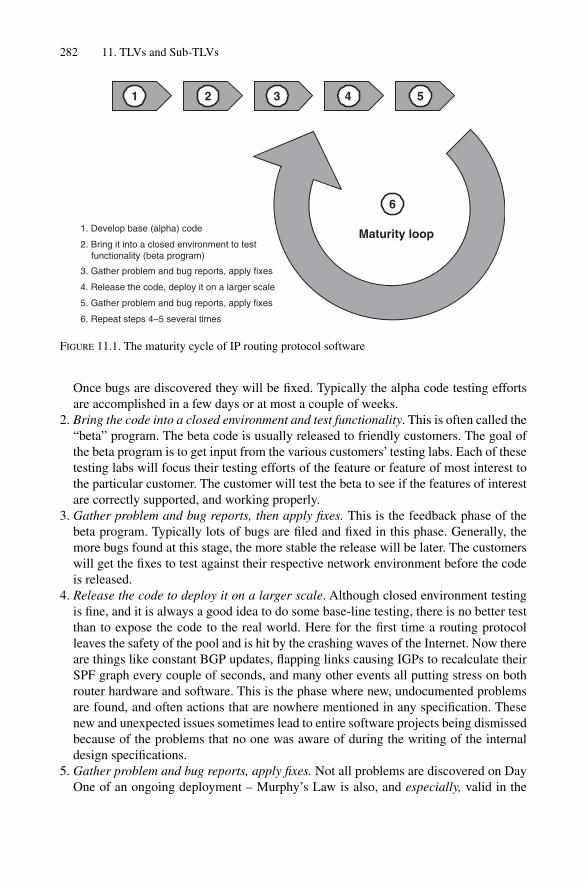
Once bugs are discovered they will be fixed. Typically the alpha code testing effortsare accomplished in a few days or at most a couple of weeks.
2. Bring the code into a closed environment and test functionality. This is often called the“beta” program. The beta code is usually released to friendly customers. The goal ofthe beta program is to get input from the various customers’ testing labs. Each of thesetesting labs will focus their testing efforts of the feature or feature of most interest tothe particular customer. The customer will test the beta to see if the features of interestare correctly supported, and working properly.
3. Gather problem and bug reports, then apply fixes. This is the feedback phase of thebeta program. Typically lots of bugs are filed and fixed in this phase. Generally, themore bugs found at this stage, the more stable the release will be later. The customerswill get the fixes to test against their respective network environment before the codeis released.
4. Release the code to deploy it on a larger scale. Although closed environment testingis fine, and it is always a good idea to do some base-line testing, there is no better testthan to expose the code to the real world. Here for the first time a routing protocolleaves the safety of the pool and is hit by the crashing waves of the Internet. Now thereare things like constant BGP updates, flapping links causing IGPs to recalculate theirSPF graph every couple of seconds, and many other events all putting stress on bothrouter hardware and software. This is the phase where new, undocumented problemsare found, and often actions that are nowhere mentioned in any specification. Thesenew and unexpected issues sometimes lead to entire software projects being dismissedbecause of the problems that no one was aware of during the writing of the internaldesign specifications.
5. Gather problem and bug reports, apply fixes. Not all problems are discovered on DayOne of an ongoing deployment – Murphy’s Law is also, and especially, valid in the
282 11. TLVs and Sub-TLVs
1. Develop base (alpha) code
2. Bring it into a closed environment to test functionality (beta program)
3. Gather problem and bug reports, apply fixes
4. Release the code, deploy it on a larger scale
5. Gather problem and bug reports, apply fixes
6. Repeat steps 4–5 several times
Maturity loop
1 2 3 4 5
6
FIGURE 11.1. The maturity cycle of IP routing protocol software

networking environment. Typically, more problems are discovered when the last fewrouters in a customer’s network are updated with the new software. If there is improp-erly functioning software in the customer’s live network, then it is the router vendor’sresponsibility to provide fast, “hot” fixes for the problems being discovered. This is ascary phase for the ISP, because sometimes the hot fix has not been subjected to thefull internal test bed, mostly because of urgency to bring the fix into the field. A fullregression test of routing software can last from a few days to many weeks, dependingon the complexity of the overall software architecture.
6. Repeat steps 4 and 5 (deploy and fix) several times. This is probably the most importantphase of all. Because this software development activity concerns the Internet, an everexpanding and growing thing, there is no such thing as software that is working andcomplete at the same time. It might be that during the software life cycle the Internetas a whole or the ISP’s network is hitting a new scaling barrier for the routing software.This is the development phase that one large router vendor refers to as the “Internetclassroom” where both ISPs and router vendors have to learn every day about thechanging environment. But this results in a feedback loop of constant improvementthrough extensibility.
The full deployment and fixing steps in the process and the repeated iteration of thesekey deploy and fix steps are increasingly important for the overall quality and maturity ofthe routing protocol software. Even if this software maturation model sounds expensiveat first for the customers, who are asked to deploy software that is admittedly incomplete,there is really no other way to complete the process. Some customer agents buying soft-ware and hardware from the router vendors might ask if the software should or could betested better and more rigorously before going into general release for customer use. Thisis a valid point. But experience has shown that even the most rigorous of testing environ-ments cannot detect all bugs or lack of needed functions in a routing protocol. Now, forthe first public release after the beta-program, enough experience and testing should havebeen done to avoid a large percentage of “severe” bugs, which are bugs that cause thefailure of the routing protocol and/or router. But less severe bugs, or feature shortcomingsin the routing protocol, often only reveal themselves during extensive and large-scaleoperations in the Internet environment.
What the deploy-and-fix steps really boil down to is the repeated application of the fol-lowing related steps:
• Deploying routing software• Getting further experience (sometimes based on a slightly changed environment), and• Improving routing software
These steps are very important for the maturity – and continued survival – of the proto-cols. Ideally, routing protocols should be almost like good wine – the older, the better.
11.1.2 Ramifications of Non-extensible Routing ProtocolsThe allowance for constant improvement of the routing protocol through added featuresand bug fixes forms the essence of the extensible routing protocol. How do non-extensible
Taxonomy for Extensibility 283

routing protocols negatively impact the maturity cycle of routing protocol software? A routing protocol becomes stable after spending enough cycles in the maturity (deploy-and-fix) loop. So what happens if this maturity cycle is disrupted by (for example) the needto add new features to the protocol? It is clear that there will always be enhancements, newcapabilities and features requested by customers dictating innovation by voting with theirdollars. No router vendor (or any type of company, for that matter) can withstand customer-originated pressure and refuse to add needed and desirable functionality to an already stableprotocol. Ironically, one of the toughest challenges for the router vendors is to strike a bal-ance between the customers desiring rock-solid, stable routing protocols and the customersat the edge of the technology pushing for innovation. So the question turns into “How do Iintroduce new functionality without harming the existing code base?” It is important to real-ize what the last part of this question states – due to the prevailing software developmentmodel, vendors do not want to disrupt the maturity cycle by creating something radicallydifferent, and so incompatible, with the existing routing protocol. It turns out that thisdesired property (extensible, but not harmful) is solely dependent on the routing protocol’sarchitecture. This architecture determines how easy it is (or is not) for the developer to incor-porate new features into the routing protocol. First of all it is hard to extend a protocol whosearchitecture was never prepared for extension. The ramification of this uphill battle will beadditional demand for time and resources for bringing the protocol to a mature state, whichmay delay new enhancements to your network. Competitively speaking, it may be that acompetitor is already provisioning services while other vendors are still testing in the labs toverify the protocol and the accompanying new features are prime-time ready.
11.1.3 What Does it Mean When a Routing Protocol Is Called Extensible?
How can anyone tell if a routing protocol is really extensible or not? There are two placesto look at in order to determine if a routing protocol is friendly to the developer (that is,ready for extensions). The two places are:
• Hellos and Capability Announcement messages• NLRI (Network Layer Reachability Information) messages
11.1.3.1 Hellos and Capability Announcement Messages
Hellos are the packets that are regularly exchanged between routers to determine if thereis basic connectivity between the routers. Since these types of packets are common andexchanged whenever adjacencies are established between routers, Hello packets are alsoa good place to indicate new capabilities in the routing protocol. These capabilities mightinclude, but are not limited to, things such as:
• Support for additional networking protocols beside IPv4 (for example, IPv6, CNLP,IPX, and so on).
• Changes and modifications to the protocol interaction (for example, the basic hand-shake procedures for the protocol).
• Changes and modifications to the topological understanding of the routing protocol (forexample, support for multiple topologies and link types, more than one area, and so on).
284 11. TLVs and Sub-TLVs
• Changes and modifications to the basic timers such as establishing a different baselinefor the timers. Think of an extension to the routing protocol that allows for sub-secondconvergence and requires other routers to re-interpret their own timers, sometimes inviolation of the original specification. For instance, a router wanting to indicate thatthe dead-timer value of 300 should not be interpreted in units of seconds (300 seconds),but should be now interpreted as a 300-millisecond dead-timer.
• Changes to the authentication scheme used on the link (for example, public-key authen-tication used instead of a simple password).
• Non-stop forwarding (also known as graceful restart) behaviour that allows neigh-bouring node to still forward traffic through a router with a failing control plane, asdescribed in draft-ietf-isis-restart-05.
11.1.3.2 NLRIs
NLRI (Network Layer Reachability Information) is a term borrowed from BGP and usedwith IGPs like ISIS and OSPF. But the idea of an NLRI can be used for virtually any net-working and routing protocol that has to pass on OSI-RM Layer 3 (L3) network prefixes(routes). The NLRI is basically a per-Layer3 protocol envelope for passing on reachabilityinformation (“if you have any packets for the IP addresses that follow, you can send themhere. I know how to reach them.”). Keeping the eventual need to transition to IPv6 in mind,any protocol should support multiprotocol extensions to a degree that one can convey bothIPv4 and IPv6 NLRIs concurrently. The concept of a per-protocol container is neededbecause, virtually every network layer protocol has different L3 address formats and rules thatrouters follow to parse them. For instance, the bit string 192.168.1/24 could and does meansomething totally different in IPv4 than in IPv6. So each prefix has to be packaged in a dedi-cated envelope telling the other routers what network layer protocol the prefix is targeted for.
It would be nice if Hellos and NLRIs formed two completely independent mechanismsof extensibility. Unfortunately, Hellos and NLRIs are related to each other. For example,if a node sends IPv6 reachability information inside an IPv6 NLRI to another router, thereceiving router has to have a way of finding out ahead of time which of its neighbourscan forward IPv6 in order to route the traffic closer to the destination. So a single look tosee if a routing protocol supports a different NLRI type is only half the story. This makesit clear that a truly extensible routing protocol must easily accommodate both new cap-abilities in its Hello Messages as well as support for different NLRIs during route prefixupdate exchanges to facilitate extensions.
Two routing protocols often cited as models of extensibility and for their ease ofadding new features while remaining stable are OSPF and IS-IS. The rest of this chapteris an analysis of how OSPF and then IS-IS achieve their extensibility.
11.2 Analysis of OSPF Extensibility
The analysis in this section is based on RFC 2328 “OSPF Version 2” Appendix A “OSPFData Formats”, and also RFC 2370 The OSPF Opaque LSA Option.
What this section basically does is try to pose some hypothetical questions of the routingprotocol. For instance, we could ask, “in what parts or fields of the routing protocol could
Analysis of OSPF Extensibility 285

OSPF extensions be placed?” Now, no one really would do this in real life. This procedureis just an exercise for the sake of finding out if a protocol is truly extensible or not. Ifthere is no place to put extensions, then the routing protocol is just not extensible, nomatter what the standard might say in this regard.
Figure 11.2 shows a generic OSPF header and an OSPF Hello in detail. One feature of the OSPF routing protocol is immediately obvious just by glancing at the figure. TheOSPF routing protocol has a frame structure aligned to 32-bit (4 bytes) boundaries. Today,32-bit alignment is merely a legacy from the times when CPU processing power wassmall and realigning a byte stream would have had a serious CPU impact. This optimiza-tion effort is considered to be a non-issue in modern networks. For CPU architectures thatstore 32-Bit integers in non-network order format (like for example the Intel x86Architecture) this optimization is even more irrelevant because for network order to hostorder conversion the stream is read in 8-bit quantities anyway). The generic OSPF headeras well as the OSPF Hello header has some occurrences of IPv4 addresses without explicitfields establishing that these addresses are in the IPv4 format. This is a bad thing, becauseit means that OSPF cannot send Hellos for any other address family such as IPv6. Howwould the parser in the receiving router know what’s inside a field like the DesignatedRouter field without implicitly expecting an IPv4 address? What if inside the address fieldis an IPv6 address, or even something else? Simply put, current OSPF extension mech-anisms cannot be extended in that way to indicate multiple address families in the header.
286 11. TLVs and Sub-TLVs
Neighbour List
Version
Router ID
Area
Hello Interval
2
Bytes
2
4
4
2
2
8
4
2
Checksum
Authentication Data
Network Mask
Options
1
4
Priority
Dead Interval
Packet Length
Type
Authentication Type
1
1
1
1
Designated Router
Backup Designated Router
4
4
N * 4
Bit01234567
Option Bit NameReservedOpaqueDemand CircuitExternal AttributesNSSA supportMulticast SupportExternalType of Service Support
Options
FIGURE 11.2. The OSPF Hello packet has no provisions for optional fields and the 8-bit optionsfield is almost fully populated

But what about using fields after the Hello message? There is plenty of room in an IPpacket (65,515 bytes for the IPMAX size field in the IP packet header. A good idea, but itwon’t work. The last field in the Hello message is the Neighbour List. The Neighbour Listis an implementation of a 3-way handshake protocol. Consider when Router A and Router Bfirst communicate. In the Hellos exchange, the Neighbour List basically lists routers,including Router A, by IP address in Router B’s Hellos in order to indicate that there isbi-directional connectivity between Router A and Router B. However, the NeighbourList lacks a Length indicator field. How does the receiver then know where the “NeighbourList” ends? Recall that the software parsing the Hello knows the length of the entireOSPF packet. Knowing this, the router simply subtracts the OSPF generic header plusthe OSPF Hello, which are in total 44 bytes. The result divided by four (each entry in theNeighbour-ID list is a 32-bit IPv4 address) and so reveals the number of neighbours thatthis specific router has “seen”.
From a purely bit-field perspective the OSPF Hello is not extensible at all. This is becauseneither re-interpretation of existing fields nor attaching new fields at the end of the frameworks to extend OSPF to other address families without breaking the base OSPF proto-col. If such a multi-family feature were added to OSPF, the result would be incompatiblewith older versions of OSPF.
Right from it first version, OSPF included an 8-bit field called the “Options Field”,which can be seen in Figure 11.2. Throughout the last decade, the Options field has beenutilized for several extensions to OSPF. These extensions include:
• O – The router supports the Opaque LSA Types 9,10,11 which are mainly used forTraffic Engineering applications
• DC – Demand circuits (circuits that are not up all the time, such as dial-ups)• EA – External LSA (deprecated, this option must no longer be used)• N/P – NSSA support (allows external routes in a stub area)• MC – Multicast OSPF (using OSPF to distribute multicast routing information)• E – Indicating ASBRs (routers redistributing routes from another routing source such
as RIP)• T – TOS (type of service) routing support
As shown in Figure 11.2, the Options field has only three unused (Reserved) bits left.So there is not-much room to extend the protocol in a backward-compatible way. Theoption negotiating mechanism in OSPF is solved quite nicely because a router receivingHellos and not having certain capabilities replies in its own Hellos with the Options fieldbits that are not supported cleared.
In the common OSPF frame there are fields indicating the Version and the Packet-Type. In Figure 11.2, the Packet-Type for the Hello is set to 1 (Hello Packet-Type) andthe Version field is set to 2 indicating OSPF protocol version 2.
Mention has just been made of the OSPF Packet-Type field. A value of 1 indicates anOSPF Hello packet. In the base specification OSPF supports five different packet types:
1. Hello2. Database description3. Link-state request
Analysis of OSPF Extensibility 287

4. Link-state update5. Link-state acknowledgment
Database description, link-state update, and link-state acknowledgment are purely forsynchronizing the link-state databases on demand. The element carrying network layerreachability information, the main source of detailed link state information, is the link-state update packet. If OSPF wants to announce IP prefixes and their related metrics,the vehicle to get this information across to other OSPF routers is the link-state updatepackets (LSAs).
The next step in exploring the extensibility of OSPF is to make sure the link-state updatepacket can be extended. Figure 11.3 shows that there is a field called Link-State Type.Simply adding new Link-State Types can extend OSPF. It is not necessary to go deeperinto what link-state types exist today and what the various packet formats look like tounderstand that this is how OSPF can be extended for new features and functions. Thisinformation is available from a number of sources. After all, this is a book about IS-ISand not a book about OSPF.
288 11. TLVs and Sub-TLVs
Version
Router ID
Area
LSA age
2
Bytes
2
4
4
2
2
8
4
2
Checksum
Authentication Data
LSA Count
Options
1
4
LSA Type
Link State ID
Packet Length
Type
Authentication Type
1
1
1
4
Advertising Router
Sequence Number
4
4
Checksum
Length
2
2
FIGURE 11.3. The LSA type field would be a possibility for extending OSPF

Consider extending OSPF by adding a new, hypothetical LSA type. The number couldbe anything not currently used or defined – LSA type 53, for example. Now, what if a routerrunning older OSPF software does not recognize the new, hypothetical LSA type 53?Should the router flood the LSA further across the network or should the router simplydiscard the update? To explain what OSPF does with extensions that the router does notunderstand, it is necessary to borrow a term from BGP terminology. The term is calledtransitivity. Certain BGP attributes are transitive as the attributes flow from BGP routerto BGP router. But the term can be applied to protocols other than BGP. Transitivity meansthat if a router cannot interpret a given message, the router will flood the message furtheracross the network anyway. Non-transitive behaviour means that a router does not for-ward an LSA that the router cannot interpret in terms of the LSA payload.
OSPF is a strictly non-transitive protocol. OSPF routers will not flood LSA types thatthe routers themselves do not understand. The ramifications of that are a bit depressing.Non-transitive OSPF behaviour means that a new feature cannot be rolled out unless allOSPF routers in a given link-state domain are updated with the new software. Given thefact that the role of the IGP is changing from the narrow role of distributing NLRI infor-mation towards a wider role with regard to a topology discovery function, it might benecessary for new OSPF features of increasing interest to use the flooding sub-system ofOSPF for distributing network-wide information. And this information must be spreadall over the network, information that not each OSPF speaker must necessarily see. I won’t flood because I do not understand behaviour is not migration-friendly, and there-fore causes a lot of headache for preparing migrations.
Fortunately, the issue of OSPF transitivity has been addressed. RFC 2370, The OSPFOpaque LSA Option, describes an enhancement to base OSPF. A set of opaque LSAs isdefined in this RFC that correct the problem with OSPF being non-transitive. Instead ofusing the BGP terminology of transitive, OSPF uses the concept of an LSA that is visible(and understandable) to some OSPF routes and yet not visible to all OSPF routers. Thenew LSAs are not transparent to all OSPF routers, but opaque to some routers, routers thatmust still pass on this LSA type through flooding nonetheless. With RFC 2370, type 9, 10and 11 LSAs now become the universal transport vehicle for routing and topology-relateddata that need to get distributed by the flooding sub-system of OSPF. With those extensionsin place, arbitrary data, including reachability information from other address families suchas IPv6, could theoretically be distributed about an OSPF routing domain. A full discus-sion of opaque LSA types in OSPF is not needed in a book on IS-IS. It is enough to notethe presence of opaque LSA types in OSPF for the purposes of extensibility.
11.3 Analysis of IS-IS Extensibility
IS-IS uses TLVs to encode Hellos, NLRIs, as well as miscellaneous other informationneeded for the IS-IS routing protocol to function properly. Virtually all these message elem-ents use Type-Length-Value (TLV) encoding to get their data across to other IS-IS routers.
11.3.1 TLV FormatFigure 11.4 shows the basic elements for TLV encoding.
Analysis of IS-IS Extensibility 289
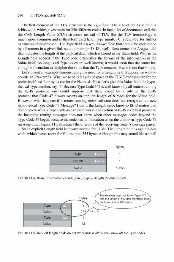
The first element of the TLV structure is the Type field. The size of the Type field is 8-bits wide, which gives room for 256 different codes. In fact, a lot of documents call thisthe Code-Length-Value (CLV) structure instead of TLV. But the TLV terminology ismuch more common and is therefore used here. Type number 0 is reserved for furtherexpansion of the protocol. The Type field is a well-known field that should be understoodby all routers in a given link-state domain (� IS-IS level). Next comes the Length fieldthat indicates the length of the payload data, which is stored in the Value field. Why is theLength field needed if the Type code establishes the format of the information in theValue field? As long as all Type codes are well known, it would seem that the router hasenough information to decipher the value that the Type contains. But it is not that simple.
Let’s invent an example demonstrating the need for a Length field. Suppose we want toencode an IPv4 prefix. What we need is 8 bytes of space in the TLV. Four bytes are for theprefix itself and four bytes are for the Netmask. Next, let’s give this Value field the hypo-thetical Type number, say 47. Because Type Code #47 is well known by all routers runningthe IS-IS protocol, one could suppose that there could be a rule in the IS-IS protocol that Code 47 always means an implicit length of 8 bytes for the Value field.However, what happens if a router running older software does not recognize our newhypothetical Type Code 47 Message? How is the Length made know to IS-IS routers thatdo not know what a Type Code 47 is? Even worse, the section of IS-IS code that parses allthe incoming routing messages does not know when other messages-codes beyond theType Code 47 begin, because the code has no indication when the unknown Type Code 47message ends. Figure 11.5 illustrates the dilemma of the receiving router’s message parser.
So an explicit Length field is always needed for TLVs. The Length field is again 8-bitswide, which leaves room for Values up to 255 bytes. Although this may sound like a small
290 11. TLVs and Sub-TLVs
Type
Length
Value
1–255
Bytes
1
1
1–255
1–255
FIGURE 11.4. Basic information encoding in (T)ype (L)ength (V)alue triplets
Type
Value
47
Bytes
1
???
1Type
Value
53
12
The receiver does not know Type #47,and the length of #47 and therefore doesnot know where #53 starts
FIGURE 11.5. Implicit length fields do not work unless all routers know all the Type codes

number (just think of a router that has hundreds of adjacencies to advertise) it has turnedout to be a sufficient size for most message types.
11.3.2 TLV EncodingFor the case of messages larger than 255 bytes, smaller message elements are scatteredacross multiple occurrences of a given Type Code. Figure 11.6 shows how a large chunk (30in this case) of IPv4 prefixes are scattered over two occurrences of Type Code 128 messages.Type Code 128, which is not hypothetical, will be discussed in more detail in Chapter 12.The only thing a router needs to know is that the basic message format of TLV #128 isrepeated occurrences of IPv4 prefixes, metrics and net masks having a fixed length of 12bytes. So each IPv4 prefix consumes 12 bytes space in the message. What the TLV encod-ing engine needs to know is the maximum amount of IPv4 prefix data that can be stored in a255 bytes sized message. As it turns out, the densest packaging is reached when 21 prefixesare squeezed into one TLV encoded message, filling up the message to 252 bytes. That stillresults in a TLV message space utilization of 98.4 per cent, which is fine for a routing proto-col. The remaining nine prefixes get stored in a second occurrence of a Type #128 message.
Interestingly, IS-IS has a uniform Type Code space for both Hellos and NLRIs. Thismeans that an arbitrary TLV can theoretically be present both in all three IS-IS packettypes. The three packet types that IS-IS generates are:
• IIHs (Hellos)• SNPs (sequence number PDUs)• LSPs (link-state PDUs)
Although this uniform Type Code space makes it easier for humans to memorize thedefined TLVs, not all TLVs are present in all three IS-IS PDU types. For instance, forauthentication information it makes no sense to limit authentication only to IIH packets,because an attacker can do a lot of harm by forging any of the PDU types.
Analysis of IS-IS Extensibility 291
Bytes
30 IPv4 prefixes(30 � 12) � 252 bytes
Type
Length
Value
21 IPv4 prefixes(21 � 12) � 252 bytes
128 1
1
252
252
Value
9 IPv4 prefixes(9 � 12) � 108 bytes
108
Type
Length
128 1
1108
FIGURE 11.6. A large chunk of IPv4 prefixes, not fitting in a single TLV encoded message, is scat-tered across multiple occurrences of the same Type Code

292
TAB
LE
11.1
.The
list
of
TLV
s th
at m
oder
n ro
uter
OSs
sup
port
.PD
U ty
pe
1516
1718
2024
2526
27L
AN
p2
p T
LVH
ello
Hel
loL
SPC
SNP
PSN
P
IS-I
S T
LVs
#So
urce
L1
L2
L1
L2
L1
L2
L1
L2
Are
a A
ddre
ss1
ISO
1058
9X
XX
XX
IS R
each
abili
ty2
ISO
1058
9X
XIS
Nei
ghbo
rs6
ISO
1058
9X
XPa
ddin
g8
ISO
1058
9X
XX
LSP
Ent
ry9
ISO
1058
9X
XX
XA
uthe
ntic
atio
n10
ISO
1058
9,R
FC35
67X
XX
XX
XX
XX
Che
cksu
m12
RFC
3358
XX
XX
XX
XE
xten
ded
IS R
each
abili
ty22
RFC
3784
XX
IS A
lias
24R
FC37
86X
XIP
inte
rnal
Rea
chab
ility
128
RFC
1195
,RFC
2966
XX
Prot
ocol
s Su
ppor
ted
129
RFC
1195
XX
XX
XIP
ext
erna
l Rea
chab
ility
130
RFC
1195
,RFC
2966
(*)
X(*
)X
IDR
P In
form
atio
n13
1R
FC11
95X
XIP
Int
erfa
ce A
ddre
ss13
2R
FC11
95X
XX
XX
TE
Rou
ter
ID13
4R
FC37
84X
XE
xten
ded
IP R
each
abili
ty13
5R
FC37
84X
XD
ynam
ic h
ostn
ame
137
RFC
2763
XX
Shar
ed li
nk r
isk
grou
p13
8dr
aft-
ietf
-isi
s-gm
pls-
exte
nsio
ns-1
9X
XR
esta
rt S
igna
ling
211
RFC
3847
XX
XM
ulti
Topo
logy
IS
Rea
chab
ility
222
draf
t-ie
tf-i
sis-
wg-
mul
ti-to
polo
gy-0
7X
XM
ulti
Topo
logi
es S
uppo
rted
229
draf
t-ie
tf-i
sis-
wg-
mul
ti-to
polo
gy-0
7X
XX
XX
IPv6
Int
erfa
ce A
ddre
ss23
2dr
aft-
ietf
-isi
s-ip
v6-0
6X
XX
XX
Mul
ti To
polo
gy I
P R
each
abili
ty23
5dr
aft-
ietf
-isi
s-w
g-m
ulti-
topo
logy
-07
XX
IPv6
Rea
chab
ility
236
draf
t-ie
tf-i
sis-
ipv6
-05
XX
Mul
ti To
polo
gy I
Pv6
Rea
chab
ility
237
draf
t-ie
tf-i
sis-
wg-
mul
ti-to
polo
gy-0
7X
Xp2
p ad
jace
ncy
stat
e24
0R
FC33
73X
IIH
Seq
uenc
e N
umbe
r24
1dr
aft-
shen
-isi
s-iih
-seq
uenc
e-00
XX
XV
endo
r Pr
opri
etar
y25
0dr
aft-
ietf
-isi
s-ex
peri
men
tal-
tlv-0
1X
XX
XX
XX
XX
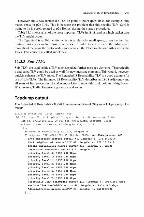
However, the 3-way handshake TLV on point-to-point (p2p) links, for example, onlymakes sense in p2p IIHs. This is because the problem that this specific TLV #240 is trying to fix is purely related to p2p Hellos, during the startup procedure.
Table 11.1 shows a list of the most important TLVs in IS-IS, and in which packet typethe TLV might occur.
The Type field is an 8-bit entity, which is a relatively small space, given the fact thatrouting protocols can live dozens of years. In order to not exhaust the 8-bit spacethroughout the years the protocol designers carried the TLV orientation further inside theTLVs. This concept is called sub-TLVs.
11.3.3 Sub-TLVsSub-TLVs are used inside a TLV to encapsulate further message elements. Theoreticallya dedicated TLV could be used as well for new message elements. This would, however,quickly exhaust the TLV space. The Extended IS Reachability TLV is a good example foruse of sub-TLVs. The Extended IS Reachability TLV describes an IS-IS Adjacency andall sorts of link properties like Maximum Link Bandwidth, Link colours, Neighbours,IP addresses, Traffic Engineering metrics and so on.
Tcpdump outputThe Extended IS Reachability TLV #22 carries an additional 69 bytes of link property infor-mation.
11:36:45.587565 OSI, IS-IS, length: 405
L2 LSP, hlen: 27, v: 1, pdu-v: 1, sys-id-len: 6 (0), max-area: 3 (0)
lsp-id: 1921.6800.1019.00-00, seq: 0x000002fd, lifetime: 1198s
chksum: 0xe984 (correct), PDU length: 405, L1L2 IS
[ … ]
Extended IS Reachability TLV #22, length: 75
IS Neighbor: 1921.6800.1021.00, Metric: 22000, sub-TLVs present (69)
IPv4 interface address subTLV #6, length: 4, 172.16.33.6
IPv4 neighbor address subTLV #8, length: 4, 172.16.33.5
Traffic Engineering Metric subTLV #18, length: 3, 22000
Unreserved bandwidth subTLV #11, length: 32
priority level 0: 9953.280 Mbps
priority level 1: 9953.280 Mbps
priority level 2: 9953.280 Mbps
priority level 3: 9953.280 Mbps
priority level 4: 9953.280 Mbps
priority level 5: 9953.280 Mbps
priority level 6: 9953.280 Mbps
priority level 7: 9953.280 Mbps
Reservable link bandwidth subTLV #10, length: 4, 9953.280 Mbps
Maximum link bandwidth subTLV #9, length: 4, 9953.280 Mbps
Administrative groups subTLV #3, length: 4, 0x00000000
[ … ]
Analysis of IS-IS Extensibility 293

In Table 11.2 you can see all current defined sub-TLVs. Chapter 14, “Traffic Engineeringand MPLS”, gives a more thorough discussion of the extended IS Reachability TLVwhich is just discussed here for the aspect of sub-TLVs.
Figure 11.7 shows a real-world example of the Extended IS Reachability TLV. In ourexample TLV, two adjacencies are reported. The first link adjacency is describing linkcharacteristics to Neighbour 1921.6800.1008.00. The cost of using this link during theSPF cycle is 250,000 as described in the Metric field. After the Metric field each TLV ter-minates with an optional sub-TLV length. If the length field is zero, then no further linkcharacteristic are reported for this adjacency. In our example there is indication that thereare 11 further bytes of link properties.
The next byte contains the first sub-TLV type. Code-point #8 is used to indicate a remoteneighbour’s IP address. The sub-TLV Code is followed by a sub-TLV Length which is setto 4. What finally follows is the value of 4 bytes describing the actual Neighbor IP Address.
The encoding of the first sub-TLV consumed 1 � 1 � 4 � 6 bytes. So there is still 5 bytes left of sub-TLV information to decode.
The next sub-TLV is code-type 18 and the sub-TLV length field indicates 3 bytes ofMetric Information. This sub-TLV carries a kind of metric information that is purelyrelated to constrained based routing (CSPF) which is further illustrated in Chapter 14,“Traffic Engineering and MPLS”.
The encoding of the second sub-TLV consumed 1 � 1 � 3 � 5 bytes. The originalsub-TLVs field of the IS reach adjacency indicated a total sub-TLV length of 11 bytes.
What the router tries to find out next is to determine the remaining size of subTLVs –it does so by subtracting the actual offset from the entire TLV length of 33 bytes. So far22 bytes (the first TLV plus the two sub-TLVs) have been processed so there must be 11
294 11. TLVs and Sub-TLVs
TABLE 11.2. The list of sub-TLVs that modern router OSs support.Sub-TLV
IS Reach Sub-TLVs # Source
Administrative Group 3 RFC3784Link Local/Remote Identifier 4 RFC3784, draft-ietf-isis-gmpls-extensions-19Link Remote Identifier 5 RFC3784IPv4 interface address 6 RFC3784IPv4 neighbor address 8 RFC3784Maximum link bandwidth 9 RFC3784Reservable link bandwidth 10 RFC3784Unreserved bandwidth 11 RFC3784Traffic Engineering Metric 18 RFC3784Link Protection Type 20 draft-ietf-isis-gmpls-extensions-19Interface Switching Capability 21 draft-ietf-isis-gmpls-extensions-19
Sub-TLV IP Reach Sub-TLVs # Source
32-Bit Administrative Tag 1 draft-ietf-isis-admin-tags-0164-Bit Administrative Tag 2 draft-ietf-isis-admin-tags-01Management Prefix Color 117 draft-ietf-isis-wg-multi-topology-07

Analysis of IS-IS Extensibility 295
bytes left. The parser therefore knows that the next 10 bytes is another IS adjacencypointing to neighbour 1921.6800.1019.00 plus an SPF metric of 22000. This second linkis not carrying any sub-TLVs hence the sub-TLV length field is being set to zero.
It has already been shown that there are several levels of information packaging insideTLVs. The Extended IS Reachability TLV #22 is a good example. It contains several ISneighbours which may contain further sub-TLVs. There is lots of room for all sort ofthings that can go wrong here. Just imagine what happens if the sub-TLV length is big-ger than the TLV length. Of course this can be avoided by all sorts of clever boundarychecking. However, no specification expresses a mandate for boundary checking. In the next section you will learn about IS-IS TLV sanity checking and how vendors havehardened their implementations to catch corrupted information.
11.3.4 TLV Sanity CheckingJon Postel postulated a famous guidance about protocol interoperability:
“Be tolerant of what you receive and strict in what you send!”
The background was that a protocol’s implementations should never assume that thereceiver will get it right and should encode its information as concisely as possible. Onthe receiving side the rule mandates that the protocol should support error detection and
Type
Length
Neighbor ID
sub LV Value
22
Bytes
1
1
ID Length (6) � 1
3
1
1
1
4
Metric
subTLVs Length
subTLV Type
subTLV Length
33
1921.6800.1008.00
250000
8
4
172.16.33.12
subTLV Value
subTLV Type
subTLV Length
18
3
12000
1
1
3
Neighbour ID ID Length (6) � 1
3
1
Metric
subTLVs Length
1921.6800.1019.00
22000
0
11
FIGURE 11.7. The sub-TLV length field of the Extended IS Reachability TLV #22 determines ifthere are any sub-TLVs following the basic IS reachability information

296 11. TLVs and Sub-TLVs
be tolerant about slightly malformed information structures. Link-state routing protocolsdo not allow implementers to follow that guidance, because of their highly distributednature.
Consider the following example: A router receives a malformed TLV and detects thatTLV is malformed. What should the router do? – further flood it or silently discard it andlog an error message? ISO 10589 mandates that flooding should be transparent through-out the area. If the flooding stops what might be the biggest harm? Worst case, a routingloop. What happens if the router floods the LSP containing the malicious LSP further?Worst case, it may crash other routers in the network who do not encompass proper TLVsanity checking. In the past 10 years of IS-IS deployment there have been at least 20 majornetwork meltdowns because corrupted LSPs got flooded further across the network. Thefirst occurrence was back in the NSFNet backbone. Dr Rekhter, now a DistinguishedEngineer with Juniper Networks, relates the following story:
“One thing that happened in the NSFNET backbone concerns the way my code han-dled ISIS link state updates. When a router received an ISIS link state update, the routerwould do some processing on that update, then flood the update to its neighbors, and thencomplete the rest of the processing on this update. Due to some bug in the code the lastpart (“the rest of the processing”) caused router crash. But since the router crashed afterit flooded the link state update to its neighbors, the update also caused the neighbors tocrash as well, resulting in the overall network meltdown.”
Implementers of the IS-IS protocol decided, because of the high inherent risk, to takea closer look to known TLVs and tightly check their formatting. The most commonfound TLV format tests are discussed in the next three subsections.
11.3.4.1 Maximum Length Checking
Each TLV and sub-TLV reports a certain length. The length field is typically an 8-bit fieldthat can express Value fields between 0 and 255 bytes. However, not all TLVs and sub-TLVs can actually consume the full range of 255 bytes.
For example, in March 2001 there was a big meltdown in a large US transit carrier’snetwork. The root cause was that a failing piece of hardware generated a malformed AreaTLV #1. Figure 11.8 illustrates the structure of the Area TLV #1. The TLV contains a setof Area Lengths and their corresponding Area-IDs. In the OSI world only Area-IDsbetween 1–13 bytes length are supported. If the Area-ID is outside that range, then theentire TLV, if not the entire LSP, is highly likely to be corrupted. After parsing the TLVthe receiving router did not check for the maximum Area-ID length and overwrote datastructures in the SPF algorithm implementation, which were expecting Area-IDs notlarger then 13 bytes. The routing software crash did not manifest itself immediately –there was unfortunately enough time to flood the killer LSP further, enough time to crashthe entire network.
Since that incident, maximum length checking is employed for the Area TLV #1.Continuing that thought there would be other TLVs that could get checked for Minimum
and Maximum Length Fields. Table 11.3 lists the minimum and maximum length valuesfor all TLVs.
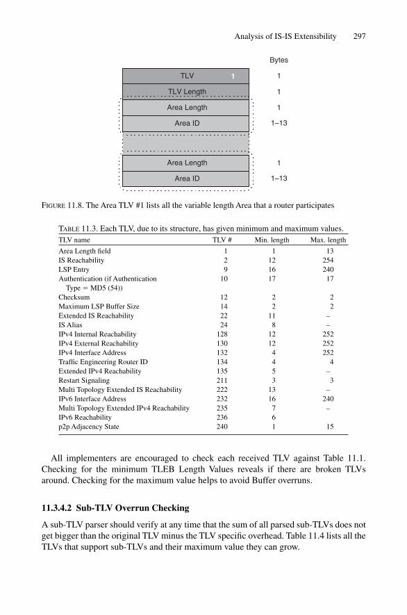
Analysis of IS-IS Extensibility 297
TLV
TLV Length
1
Bytes
1
1
1
1–13
Area Length
Area ID
1
1–13
Area Length
Area ID
FIGURE 11.8. The Area TLV #1 lists all the variable length Area that a router participates
TABLE 11.3. Each TLV, due to its structure, has given minimum and maximum values.TLV name TLV # Min. length Max. length
Area Length field 1 1 13IS Reachability 2 12 254LSP Entry 9 16 240Authentication (if Authentication 10 17 17
Type � MD5 (54)) Checksum 12 2 2Maximum LSP Buffer Size 14 2 2Extended IS Reachability 22 11 –IS Alias 24 8 –IPv4 Internal Reachability 128 12 252IPv4 External Reachability 130 12 252IPv4 Interface Address 132 4 252Traffic Engineering Router ID 134 4 4Extended IPv4 Reachability 135 5 –Restart Signaling 211 3 3Multi Topology Extended IS Reachability 222 13 –IPv6 Interface Address 232 16 240Multi Topology Extended IPv4 Reachability 235 7 –IPv6 Reachability 236 6p2p Adjacency State 240 1 15
All implementers are encouraged to check each received TLV against Table 11.1.Checking for the minimum TLEB Length Values reveals if there are broken TLVsaround. Checking for the maximum value helps to avoid Buffer overruns.
11.3.4.2 Sub-TLV Overrun Checking
A sub-TLV parser should verify at any time that the sum of all parsed sub-TLVs does notget bigger than the original TLV minus the TLV specific overhead. Table 11.4 lists all theTLVs that support sub-TLVs and their maximum value they can grow.
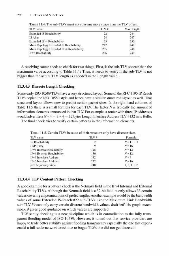
298 11. TLVs and Sub-TLVs
TABLE 11.4. The sub-TLVs must not consume more space than the TLV offers.TLV name TLV # Max. length
Extended IS Reachability 22 244IS Alias 24 247Extended IPv4 Reachability 135 250Multi Topology Extended IS Reachability 222 242Multi Topology Extended IPv4 Reachability 235 248IPv6 Reachability 236 249
A receiving router needs to check for two things. First, is the sub-TLV shorter than themaximum value according to Table 11.4? Then, it needs to verify if the sub-TLV is notbigger than the actual TLV length as encoded in the Length value.
11.3.4.3 Discrete Length Checking
Some early ISO 10589 TLVs have a very structured layout. Some of the RFC 1195 IP ReachTLVs copied the ISO 10589 style and hence have a similar structured layout as well. Thatstructured layout allows now to predict certain packet sizes. In the right-hand columns ofTable 11.5 there is a small formula for each TLV. The factor N is typically the amount ofinformation elements announced in that TLV. For example, a router with three IP addresseswould advertise a N * 4 � 3 * 4 � 12 bytes Length Interface Address TLV #132 in is Hello.
The final check tries to verify certain patterns in the information elements.
TABLE 11.5. Certain TLVs because of their structure only have discrete sizes.TLV name TLV # Formula
IS Reachability 2 N * 11 � 1LSP Entry 9 N * 16IPv4 Internal Reachability 128 N * 12IPv4 External Reachability 130 N * 12IPv4 Interface Address 132 N * 4IPv6 Interface Address 232 N * 16p2p Adjacency State 240 1, 5, 11, 15
11.3.4.4 TLV Content Pattern Checking
A good example for a pattern check is the Netmask field in the IPv4 Internal and ExternalReachability TLVs. Although the Netmask field is a 32-bit field, it only allows 33 certainvalues covering all permutations of prefix lengths. Another example would be the bandwidthvalues of some Extended IS-Reach #22 sub-TLVs like the Maximum Link Bandwidthsub-TLV #9 can only carry certain discrete bandwidth values. draft-ietf-isis-gmpls-exten-sion-19 gives good guidance on which values are supported.
TLV sanity checking is a new discipline which is in contradiction to the fully trans-parent flooding model of ISO 10589. However, it turned out that service providers arehappy to trade better stability against flooding transparency especially the one that experi-enced a full-scale network crash due to bogus TLVs that did not get detected.
Conclusion 299
299
11.4 Conclusion
Based upon this chapter’s examination of the Hellos and the NLRI carrying packets, inboth OSPF and IS-IS, OSPFv2 is not quite as extensible as IS-IS.
On the Hello side, OSPFv2 in general lacks extensibility. For the NLRI carrying packets,OSPF now contains a set of so-called “Opaque LSAs” that could be used to carry exten-sible information for additional address families. But to address the non-extensibility inOSPF in conjunction with the ongoing deployment of IPV6, the OSPF protocol design-ers had to develop a whole new version of OSPF. And unfortunately, OSPFv3 does nothave much in common with OSPFv2, since the code was mostly a rewrite from scratch,so it doesn’t use all the stable code of the OSPFv2 version. All routing software has toundergo a maturity process to become stable enough for productive use in the Internetbackbones of the world and OSPFv3 maturity may take a little longer as it tries to be allthings to all packets.
Compared to OSPF, IS-IS is almost like a case study on how to do it right the first time.From day one, IS-IS has been designed to stay neutral no matter which Network Layerprotocol information it had to transport. IS-IS has always been effectively multi-protocolready: in the 1980s it was used for routing CNLP traffic; in the 1990s IPv4 traffic wasadded; and, since 2001, IPv6 has been efficiently carried. It helps when the message elem-ents and packet types of the base IS-IS routing protocol use the proper TLV encoding. Inaddition, special precautions have been made not to exhaust the small 8-bit code spacethrough use of sub-TLVs, even in the newer TLVs. TLVs and sub-TLVs turn out to be apowerful vehicle to further extend the protocol. Due to the extra complexity of sub-TLVencoding and tight sanity checks based on known TLV structure, before loading TLVcontents into the link-state database are recommended.
Finally, the code changes from the IPv4 to an IS-IS supporting IPv6 required only400–600 lines of code, not an entire rewrite of the protocol. It is unlikely that active rout-ing of IPv6 prefixes will do any harm to the base stability of the IS-IS code.
Adapting in a constantly changing environment is what Darwin’s Law is all about.When it comes to routing protocols, extensibility is a prerequisite for routing protocolevolution. It is the authors opinion that IS-IS adapts better than OSPF, which is why itwill continue to prevail in the largest routed networks in the world.

12
IP Reachability Information
IS-IS was ready from day one for extensibility. Originally intended to route CLNP pre-fixes, today IS-IS carries routing information about a variety of networking protocolsincluding IPv4 and IPv6. In this chapter you will learn about the various places where IPprefixes or IP reachability information, which is the IS-IS term, is encoded. Support for IP prefixes came in three waves. The chapter covers both the old-style (first generation)and the new-style (second generation) TLVs. Additionally, the limitations of the first-generation IPv4-related TLVs defined in the Integrated IS-IS Routing specification (RFC1195) will be highlighted. Finally, some of the reasoning surrounding the particular prob-lems that the more recent traffic-engineering TLVs solve will be explained.
IS-IS has multiple places to convey IP reachability information. To understand why theIP-related TLVs have been re-engineered continually, it is necessary to take advantage ofhindsight and consider the times when a specific protocol decision was made. Therefore,before exploring the style of the IP TLVs, a look at one of the original ISO 10589 TLVs isneeded. Of course ISO 10589 is totally unrelated to IP; however, to acquire an understand-ing of how ISO 10589 encodes information, it is a good idea to also get a better under-standing of why the first generation of IP TLVs are the way they are.
12.1 Old-style Topology (IS-Reach) Information
Figure 12.1 shows how IS-IS encodes neighbour reachability information in the ISReachability TLV #2. The TLV conveys pure router-to-router connectivity informationand is unrelated to IP. The first byte is the Virtual Flag, which is either set to zero or one.Typically this is set to zero. It is only set to 1 in Level 2 LSPs and indicates that this linkis used to repair an area partition. However, partition repair isn’t something that a proto-col should address. Typically partitioning of Level 1 areas is avoided by putting enoughlinks in the area. IOS supports area partitioning for CLNP. However, JUNOS lacks sup-port for healing broken, partitioned areas. Therefore the least common denominator isthe simplistic design rule: “Never let an area get partitioned”, and try to avoid partitioningof an area by throwing enough links at the problem.
After the virtual flag there is a basic structure of 11 bytes that may be repeated through-out the TLV. That 11-byte structure holds 4 bytes of metric-related information and 6 bytes of System-ID appended with the one-byte Pseudonode-ID. Interestingly, the basicISO 10589 specification supports multidimensional metrics. There are distinct metrics
301

for Delay, Error, Expense and a mandatory default metric. The basic idea behind this schemeis that each router computes four distinct “topologies” by running a dedicated SPF oper-ation for each. However, at the time IS-IS was first deployed (end of the 1980s) peoplewere cautious about using CPU cycles and therefore only computed the mandatory SPFtopology, which is the default topology. If IS-IS would have been first deployed at theend of the 1990s, computing distinct SPF trees probably would have not been much ofan issue due to the massive processing power available even in embedded router systems.For routing IP, the IS-IS implementation of IOS and JUNOS does not support computa-tion of anything but the default topology. Both only propagate the default metric andignore any other metrics during receipt and during the SPF run. IOS, however, does sup-port multidimensional metrics for routing CLNP, as already mentioned.
Each of the four possible metrics is represented by a dedicated byte. The most signifi-cant bit (MSB) of the respective metric byte indicates what additional metrics an individ-ual router supports. Typically the MSB is set in the Delay, Expense and Error metrics, whichindicate that the metric is not supported. Next to the MSB there is the Internal/Externalbit, which expresses whether the Metric is comparable or not. Internal means it is compar-able, while External means it is not. (Internal metrics are always based on the same rout-ing protocol, while externals metrics are independent of IS-IS.) Typically the I/E bit is set to
302 12. IP Reachability Information
TLV Type
TLV Length
Virtual Flag
Neighbour ID
2
Bytes
1
1
1
1
1
1
1
ID Length (6) �1
N*11 � 1
0
Default MetricR0
I/E0
Delay MetricS1
I/E0
Expense MetricS1
I/E0
Error MetricS1
I/E0
Neighbour ID
1
1
1
1
ID Length (6) �1
Default MetricR0
I/E0
Delay MetricS1
I/E0
Expense MetricS1
I/E0
Error MetricS1
I/E0
FIGURE 12.1. The IS-Reachability TLV is the blueprint for all the old-style Reachability TLVsencompassing 6-bit metrics

zero, indicating that the metric is comparable. Confused? Don’t worry! Simply assume theI/E bit is always set to zero – in this TLV the I/E bit has no real practical meaning. Next,there are 6 bits that hold the metric information. Six bits can only express routing metricsranging from 0 to 63, which is quite limited these days. Once again, the design choice ofusing 6 bits goes back to the anxiousness about the SPF calculation consuming too manyCPU cycles.
In every step of the SPF calculation a sorting function needs to be executed. One canoptimize that sorting function through the use of linear arrays. Consider Figure 12.2 wherea router’s preliminary metric during the SPF calculation is 456. Now the process needsto find out if there are any other routers offering a better path to a given destination (theSystem-ID) by applying a sorting function. Using index arrays, one can skip that sortingfunction. All that need be done is store a pointer to the System-ID at the 456th entry inthe array. If the array gets traversed from zero to the end, the first non-null pointer mustbe the highest value. This implementation has the disadvantage that it consumes mem-ory. By limiting the Link Metric to 63 and the Aggregated Metric to 1023, IS-IS makessure that the indexing function does not consume too much memory. This is another placewhere CPU/memory constraints have made their way into the IS-IS protocol. In hindsight,almost always where protocol designers tried to address a particular CPU/memory/environment shortage issue of the time by protocol properties, those protocol propertiesfinally got deprecated over time. It turned out that protocols live much longer than micro-processors or memory chip restrictions do.
Old-style Topology (IS-Reach) Information 303
0
SysID 1921.6800.1008.00Metric 456
1
2
3
4
5
455
1023
456
FIGURE 12.2. Index arrays helped to speed up search operations
For lower bandwidth links the limitation to just 63 distinct metric values was not muchof an issue, because there was not much disparity between the smallest and the largestbandwidth links in a network. Consider (for instance) a DS0 (64 Kbps) circuit and a T1(1.544 Mbps) circuit. The T1 has 24 times the bandwidth of the DS0. Inverse bandwidth
metric schemes are commonly used (since the lower the metric, the more attractive theroute), so setting the T1 line to a metric of 1 and the DSO to a metric of 24 provides gooddifferentiation between the two bandwidths in the metric space. Now, consider that thehighest bandwidth in the network becomes an OC-3/STM-1 circuit capable of carrying155 Mbps. Assign the lowest-cost metric to the high-speed circuit, as before. About 100times the capacity of a single T1 circuit fits into an OC-3/STM-1 circuit, so assign a met-ric of 100 to the T1. Stop! Assigning a metric of 100 doesn’t work because there are only6 bits available. The metric must be “clipped” to 63. Continuing with the 155 Mbpsexample, re-doing the calculation for the DS0 again exposes the limitations of a 6-bit met-ric space. About 2400 DS0s fit into an OC-3/STM-1 circuit. However, since there is nobigger metric, once again clip the metric to 63. The end result is that, from an IS-IS per-spective, the DS0 link becomes now indistinguishable to the T1 line, as both metrics arenow 63. That increasing disparity of IGP metrics became the motivation to introduce newTLVs that have a broader metric field than just 6 bits (called wide-metrics in IS-IS).
12.2 Old-style IP Reach (RFC 1195) Information
It is best to demonstrate the way of thinking embodied in the ISO 10589-defined TLVsfirst. Then it is easier to catch the spirit of the IP reachability information, which is verysimilar to the IS-Reach TLV #2.
RFC 1195 specifies six new IP-related TLVs that are used to convey IP reachabilityinformation. Two of the 6 TLVs became deprecated and are not used anymore. Theremaining 4 TLVs are used for a variety of functions, like transporting IP routes, inform-ing neighbours of new capabilities and troubleshooting ease.
12.2.1 Internal IP Reachability TLV #128The Internal IP Reachability TLV #128 is probably the most important of the RFC 1195-defined TLVs. It conveys internal routing information, which is to say, directly con-nected routes. Figure 12.3 shows the basic structure of TLV #128. Please refer to Figure12.1 for comparison. Correct – they look very similar. The structure basically starts, as inISO 10589, with the same 4 bytes of metric information. The Metric fields are still 6 bits.Although broader metrics would not have an impact on CPU cycles (this is just leaf-information), the protocol designers decided to stay consistent with the spirit of ISO10589. The IP Network Number and the Netmask follow after the 4 Metric bytes. Thesefields have these names because it was common at the beginning of the 1990s to specifyIP reachability information not as prefixes and prefix lengths but rather as networks andnetwork masks.
The internal IP Reachability TLV gets automatically advertised when IS-IS is run onan interface with a configured IP address, or through use of the passive option.
Whenever IS-IS is run on an interface, once an adjacency forms, all IPv4 addresses onthat interface are encoded using TLV #128 in the router’s LSP. Alternatively, if the routerneeds to be configured to advertise a sub-net but not form an adjacency (there are validreasons to do this, as discussed in Chapter 16), use the passive option. The passive
304 12. IP Reachability Information

option is a way to include an IP sub-net in the link-state announcement, however, thereis no attempt to establish an adjacency over that link. This is achieved by suppressing allIntermediate Systems to Intermediate Systems Hellos (IIHs).
The passive option is available on both IOS and JUNOS. Consider the followingtwo configuration examples.
JUNOS configurationIn JUNOS the passive option is a per-level or alternatively a per-interface property.
[edit]
hannes@Frankfurt# show
[ … ]
protocols {
isis {
interface fe-4/2/0.0 {
level 2 passive;
}
Old-style IP Reach (RFC 1195) Information 305
TLV Type
TLV Length
IP Address
128
Bytes
1
1
1
1
1
1
4
4
N*12
Default MetricR0
I/E0
Delay MetricS1
I/E0
Expense MetricS1
I/E0
Error MetricS1
I/E0
1
1
1
1
Default MetricR0
I/E0
Delay MetricS1
I/E0
Expense MetricS1
I/E0
Error MetricS1
I/E0
SUbnet Mask
IP Address 4
4SUbnet Mask
FIGURE 12.3. Structure of the IP Reachability TLV #128
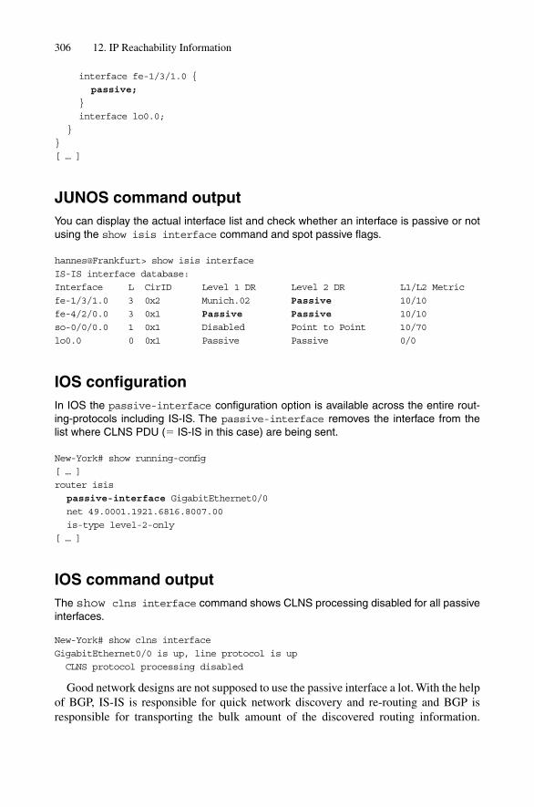
interface fe-1/3/1.0 {
passive;
}
interface lo0.0;
}
}
[ … ]
JUNOS command outputYou can display the actual interface list and check whether an interface is passive or notusing the show isis interface command and spot passive flags.
hannes@Frankfurt> show isis interface
IS-IS interface database:
Interface L CirID Level 1 DR Level 2 DR L1/L2 Metric
fe-1/3/1.0 3 0x2 Munich.02 Passive 10/10
fe-4/2/0.0 3 0x1 Passive Passive 10/10
so-0/0/0.0 1 0x1 Disabled Point to Point 10/70
lo0.0 0 0x1 Passive Passive 0/0
IOS configurationIn IOS the passive-interface configuration option is available across the entire rout-ing-protocols including IS-IS. The passive-interface removes the interface from thelist where CLNS PDU (� IS-IS in this case) are being sent.
New-York# show running-config
[ … ]
router isis
passive-interface GigabitEthernet0/0
net 49.0001.1921.6816.8007.00
is-type level-2-only
[ … ]
IOS command outputThe show clns interface command shows CLNS processing disabled for all passiveinterfaces.
New-York# show clns interface
GigabitEthernet0/0 is up, line protocol is up
CLNS protocol processing disabled
Good network designs are not supposed to use the passive interface a lot. With the helpof BGP, IS-IS is responsible for quick network discovery and re-routing and BGP isresponsible for transporting the bulk amount of the discovered routing information.
306 12. IP Reachability Information

In newer versions of IOS there is even a knob called passive-only which reduces theannouncements of IP reachability information in IS-IS to a bare minimum, which is toannounce the loopback interface only. In JUNOS similar behaviour can be created usingrouting policies. More about routing policy design philosophy and use of the passive-only knob appears in Chapter16.
12.2.2 Protocols Supported TLV #129The Protocols Supported TLV makes IS-IS a true multiprotocol IGP. Using this TLV anIS-IS router can tell other routers what protocols it speaks. It is basically an envelope forProtocol Capability Codes. The Protocols Supported TLV is transmitted in Hellos andalso in LSPs. It contains 1-byte Network Layer Protocol IDs (NLPIDs, one for each proto-col that a router speaks on a per-interface (IIH), or on a per router basis (LSP)). The two most important NLPIDs are 0xCC, indicating IPv4 forwarding capability, and 0x8eindicating IPv6 forwarding capability. Table 12.1 shows a list of common NLPIDs.
For example, if an IS-IS v4-only router does not find this TLV or the NLPID contain-ing IPv4 (0xCC) in the Hello from one of its neighbours, it keeps the adjacency down.Similarly, if a router speaks IPv4 on any interface, it will tell others that it globallyspeaks IPv4 and announce that capability in its LSP. If the NLPID is missing in theProtocol Supported TLV, then the router will be disregarded entirely during a SPF run.Chapter 13, “IS-IS Extensions”, takes a closer look into this TLV and discusses the lim-itation specifically with regard to transport of new Network Layer Protocols like IPv6. Itwill be shown that, especially given the “router-global” nature of that TLV in LSPs, thereis a problem when computing non-congruent Network Layer topologies. Furthermore, inChapter 10 the exact steps and the role of TLV#129 during the SPF run was explored ingreat detail.
Old-style IP Reach (RFC 1195) Information 307
TABLE 12.1. In the OSI world every protocol has a one-byteNetwork Protocol ID, even for non-OSI protocols.Code point Code point name
0x00 NULL0x01 T.700x02 X.290x03 X.6330x08 Q.931, Q.932, Q.933,
X.36, ISO 11572,ISO 11582
0x09 Q.29310x0c Q.21190x81 CLNP0x82 ES-IS0x83 IS-IS0x85 IDRP0x8a X25 ES-IS0x8e IPv60xcc IPv40xcf PPP

IOS and JUNOS work very differently with regard to when this TLV is sent in a Hellomessage and when it will be suppressed. IOS makes a general differentiation if an interfaceis used for pure CLNP routing or also for integrated IP routing. As soon as the iprouter isis and a valid ip address <address> <mask> are configured onan IOS platform this TLV appears in the Hello PDUs. If one of the two statements ismissing, generation of that TLV is suppressed.
Tcpdump outputAs soon as the ip router isis configuration statement plus a valid ip address<address> <mask> is configured on an IOS platform you will see the Protocols SupportedTLV in IIHs indicating that this router understands IPv4 on this circuit.
11:35:23.248504 OSI, IS-IS, length: 63
p2p IIH, hlen: 20, v: 1, pdu-v: 1, sys-id-len: 6 (0), max-area: 3 (0)
source-id: 1921.6800.0012, holding time: 30s, Flags: [Level 2 only]
circuit-id: 0x01, PDU length: 63
Point-to-point Adjacency State TLV #240, length: 1
Adjacency State: Up (0)
Protocols supported TLV #129, length: 1
NLPID(s): IPv4 (0xcc)
IPv4 Interface address(es) TLV #132, length: 4
IPv4 interface address: 172.16.12.14
Area address(es) TLV #1, length: 4
Area address (length: 3): 49.0001
JUNOS had the advantage of being introduced to the market at a time when there wasno need to support CLNP routing any longer. Therefore the pure-CLNP-routing case couldeasily be ignored. IS-IS in JUNOS is meant to transport IPv4 and IPv6 prefixes only. IS-IS is by definition multiprotocol, so JUNOS always generates the Protocols SupportedTLV #129 irrespective of whether an IPv4 or IPv6 address is configured on that interface.The explanation why the NLPIDs are set unconditionally is deferred to Chapter 13, “IS-ISExtensions”, which gives a better overview by example of the IPv6 transition.
Tcpdump outputSince Version 5.1 JUNOS unconditionally generates a Protocols Supported TLV with theNLPIDs of IPv4 (0xCC) and IPv6 (0x8e) in both Hello and LSP PDUs.
01:32:47.162118 OSI, IS-IS, length: 63
p2p IIH, hlen: 20, v: 1, pdu-v: 1, sys-id-len: 6 (0), max-area: 3 (0)
source-id: 1921.6800.0008, holding time: 27s, Flags: [Level 2 only]
circuit-id: 0x01, PDU length: 63
Point-to-point Adjacency State TLV #240, length: 15
Adjacency State: Up (0)
308 12. IP Reachability Information
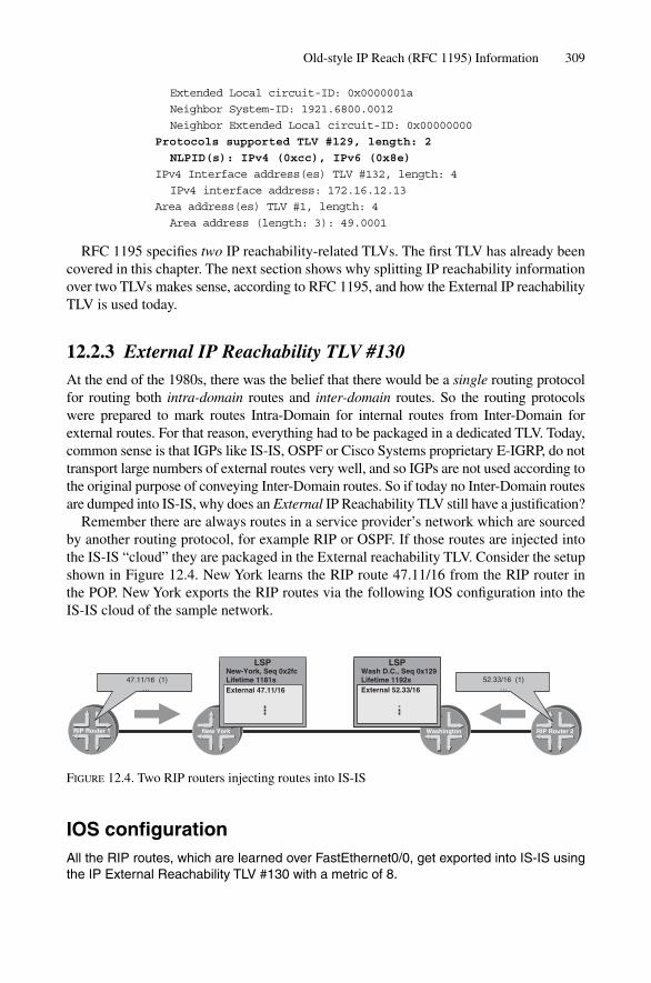
Extended Local circuit-ID: 0x0000001a
Neighbor System-ID: 1921.6800.0012
Neighbor Extended Local circuit-ID: 0x00000000
Protocols supported TLV #129, length: 2
NLPID(s): IPv4 (0xcc), IPv6 (0x8e)
IPv4 Interface address(es) TLV #132, length: 4
IPv4 interface address: 172.16.12.13
Area address(es) TLV #1, length: 4
Area address (length: 3): 49.0001
RFC 1195 specifies two IP reachability-related TLVs. The first TLV has already beencovered in this chapter. The next section shows why splitting IP reachability informationover two TLVs makes sense, according to RFC 1195, and how the External IP reachabilityTLV is used today.
12.2.3 External IP Reachability TLV #130At the end of the 1980s, there was the belief that there would be a single routing protocolfor routing both intra-domain routes and inter-domain routes. So the routing protocolswere prepared to mark routes Intra-Domain for internal routes from Inter-Domain forexternal routes. For that reason, everything had to be packaged in a dedicated TLV. Today,common sense is that IGPs like IS-IS, OSPF or Cisco Systems proprietary E-IGRP, do nottransport large numbers of external routes very well, and so IGPs are not used according tothe original purpose of conveying Inter-Domain routes. So if today no Inter-Domain routesare dumped into IS-IS, why does an External IP Reachability TLV still have a justification?
Remember there are always routes in a service provider’s network which are sourcedby another routing protocol, for example RIP or OSPF. If those routes are injected intothe IS-IS “cloud” they are packaged in the External reachability TLV. Consider the setupshown in Figure 12.4. New York learns the RIP route 47.11/16 from the RIP router in the POP. New York exports the RIP routes via the following IOS configuration into the IS-IS cloud of the sample network.
Old-style IP Reach (RFC 1195) Information 309
RIP Router 1 RIP Router 2
47.11/16 (1)…
52.33/16 (1)…
WashingtonNew York
LSP
External 47.12/16
New- York, Seq 0x2fcLifetime 1181s
LSP
External 47.11/16
New-York, Seq 0x2fcLifetime 1181s
LSP
External 47.12/16
Wash D.C., Seq 0x129Lifetime 1192s
LSP
External 52.33/16
Wash D.C., Seq 0x129Lifetime 1192s
FIGURE 12.4. Two RIP routers injecting routes into IS-IS
IOS configurationAll the RIP routes, which are learned over FastEthernet0/0, get exported into IS-IS usingthe IP External Reachability TLV #130 with a metric of 8.

New-York# show running-config
[ … ]
! this is the interface to the RIP router
interface FastEthernet0/0
ip address 172.16.67.133 255.255.255.252
router rip
network 172.16.0.0
router isis
net 49.0001.1921.6800.1189.00
redistribute rip metric 8
[ … ]
New York’s LSP looks in the tcpdump packet trace as follows:
Tcpdump outputA redistributed RIP route shows up in the LSP as an IP External Reachability TLV:
14:48:32.234806 OSI, IS-IS, length: 405
L2 LSP, hlen: 27, v: 1, pdu-v: 1, sys-id-len: 6 (0), max-area: 3 (0)
lsp-id: 1921.6800.1189.00-00, seq: 0x000002fd, lifetime: 1198s
chksum: 0xe984 (correct), PDU length: 405, Flags: [ L1L2 IS ]
[ … ]
IP External reachability TLV #130, length: 12
IPv4 prefix: 47.11/16
Default Metric: 8, Internal, Distribution: up
IS Reachability TLV #2, length: 67
IsNotVirtual
IS Neighbor: 0000.0000.0003.02, Default Metric: 10, Internal
IS Neighbor: 0000.0000.0003.02, Default Metric: 10, Internal
[ … ]
You can also spot the IP External TLVs by looking into the isis database using theshow isis database command.
IOS command outputThe bold marked output represents the content transported using the IP ExternalReachability LSP, which can be displayed using the show isis database command.
Amsterdam# show isis database verbose
[ … ]
IS-IS Level-2 Link State Database
LSPID LSP Seq Num LSP Checksum LSP Holdtime ATT/P/OL
Amsterdam.00–00 0x00000762 0x6467 732 0/0/0
NLPID: 0xCC 0x8E
310 12. IP Reachability Information

Area Address: 49.0001
IP Address: 192.168.1.1
Metric: 10 IS London.02
Metric: 10 IP-External 172.16.33.2 255.255.255.252
[ … ]
In JUNOS the external prefixes can be spotted at two places of the show isisdatabase extensive command line output.
JUNOS command outputJUNOS yields information at two places of the show isis database command line out-put. First, at the LSP Overview Section next to LSP-Name, Sequence Number, Checksumand Lifetime Information and then in the detailed TLV Breakdown.
hannes@olive-2> show isis database extensive
[...]
IS-IS level 2 link-state database:
New-York.00-00 Sequence: 0x3a, Checksum: 0x249e, Lifetime: 64986 secs
IS neighbor: Wash-D.C..02 Metric: 24
IP prefix: 47.11.0.0/16 Metric: 8 External
IP prefix: 172.16.1.0/24 Metric: 24 Internal
IP prefix: 192.168.1.2/32 Metric: 0 Internal
[ … ]
TLVs:
Area address: 49.0001 (3)
Speaks: IP
Speaks: IPv6
IP router id: 192.168.1.2
IP address: 192.168.1.2
Hostname: olive-2
IS neighbor: Wash-D.C., Internal, Metric: default 24
IP prefix: 192.168.1.2/32, Internal, Metric: default 0
IP prefix: 172.16.1.0/24 Metric: default 63
IP external prefix: 47.11.0.0/16, Internal, Metric: default 8
No queued transmissions
Finally, look at a configuration example for JUNOS, which has the same effect as theabove described IOS configuration.
In JUNOS all exchange of routes between routing protocols have to go through policieswhich are defined under the policy-options configuration branch. Each policyconsists of one or more from and then parts. The from clause means more like “if”,which is a bit counterintuitive, as one would understand from as something like “origin”at first. However the from statement always takes the inet.0 Routing Table as input andcomputes a subset of these routes. The then portion tells what to do with the prefixes thatmatch the from part. In our example, the policy rip-routes-to-isis takes all
Old-style IP Reach (RFC 1195) Information 311

routes in the main routing table inet.0 that match the from part. The from part matches allroutes, all of which have been learned through RIP, and computes a list of prefixes plus rele-vant attributes like Metrics. Once the policy is called under the protocols isis sectionthe previously computed list of routes will get inserted into an IS External ReachabilityTLV #130.
JUNOS configurationIn JUNOS a policy needs to scan the main routing table inet.0 for all routes that arelearned via RIP. They get set to a metric of 8 and, through use of the export statementunder the protocols isis section, are exported into IS-IS using the IP ExternalReachability TLV #130.
New-York# show configuration
[ … ]
protocols {
isis {
export rip-routes-to-isis
interface so-7/0/0.0;
interface lo0.0;
}
rip {
group washington-POP {
neighbor fe-0/1/0.0;
}
}
}
policy-options {
policy-statement rip-routes-to-isis {
from protocol rip;
then {
metric 8;
accept;
}
}
}
[ … ]
Figure 12.5 shows that the External IP Reachability TLV #130 shares exactly the same format as the IP Internal Reachability TLV #128. The only difference is that certaincombinations of the TLV Type and the Internal/External Bit of the Metric Bytes are not valid.
More about the valid and invalid combinations of the both TLVs, which finally led to thedemise of the old-style IP-Reach TLVs, is covered in the section that discussed the extendedIP Reachability TLV 135.
312 12. IP Reachability Information

12.2.4 Inter-Domain Information Type TLV #131The Inter-Domain Type TLV is related to the belief that Inter-Domain routes should betransported in the External IP Reachability TLV #130. It ought to give further evidenceabout the routing domain from where these routes have been obtained. This TLV hasbecome obsolete, as Inter-Domain routes are not dumped into IS-IS anymore. Figure 12.6shows the basic structure of that TLV.
The first byte contains information about the format of the Inter-Domain InformationValue that follows. Three types are defined: Type 0 and 1 indicate reserved or local usageand Type 2 indicates that a two-byte AS number follows. Typically this Information TLVis inserted before an IP External Reachability TLV #130 and helps the receiving router tostore AS-related information (where the route came from) with the external routes. NeitherIOS nor JUNOS make use of this TLV, due to the harm to scaling that redistribution ofInter-Domain routes into IS-IS causes.
Old-style IP Reach (RFC 1195) Information 313
TLV Type
TLV Length
IP Address
130
Bytes
1
1
1
1
1
1
4
4
N*12
Default MetricR0
I/E0
Delay MetricS1
I/E0
Expense MetricS1
I/E0
Error MetricS1
I/E0
1
1
1
1
Default MetricR0
I/E0
Delay MetricS1
I/E0
Expense MetricS1
I/E0
Error MetricS1
I/E0
SUbnet Mask
IP Address 4
4SUbnet Mask
FIGURE 12.5. Structure of the External IP Reachability TLV #130
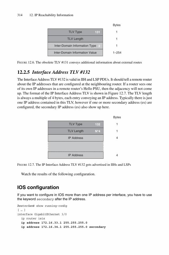
12.2.5 Interface Address TLV #132The Interface Address TLV #132 is valid in IIH and LSP PDUs. It should tell a remote routerabout the IP addresses that are configured at the neighbouring router. If a router sees oneof its own IP addresses in a remote router’s Hello PSU, then the adjacency will not comeup. The format of the IP Interface Address TLV is shown in Figure 12.7. The TLV lengthis always a multiple of 4 bytes, each entry conveying an IP address. Typically there is justone IP address contained in this TLV, however if one or more secondary address (es) areconfigured, the secondary IP address (es) also show up here.
314 12. IP Reachability Information
TLV Type
TLV Length
Inter-Domain Information Type
131
Bytes
1
1
1
1–254
2
Inter-Domain Information Value
FIGURE 12.6. The obsolete TLV #131 conveys additional information about external routes
TLV Type
TLV Length
IP Address
132
Bytes
1
1
4
4
N*4
IP Address
FIGURE 12.7. The IP Interface Address TLV #132 gets advertised in IIHs and LSPs
Watch the results of the following configuration.
IOS configurationIf you want to configure in IOS more than one IP address per interface, you have to usethe keyword secondary after the IP address.
Amsterdam# show running-config[ … ]
interface GigabitEthernet 3/0
ip router isis
ip address 172.16.33.1 255.255.255.0
ip address 172.16.34.1 255.255.255.0 secondary

router isis
net 49.0001.1921.6801.1001.00
is-type level-1
[ … ]
Once we start tcpdump on a workstation, which is on the LAN, we will get a similaroutput. Note that the number in brackets behind the TLV is the length of that TLV.
Tcpdump outputAll the configured IP addresses are listed in the IP Interface Address TLV.
16:19:27.486634 OSI, IS-IS, length: 84
L1 Lan IIH, hlen: 27, v: 1, pdu-v: 1, sys-id-len: 6 (0), max-area: 3 (0)
source-id: 0000.0000.0003, holding time: 40s, Flags: [Level 1, Level 2]
lan-id: 0000.0000.0003.02, Priority: 70, PDU length: 84
IS Neighbor(s) TLV #6, length: 6
IS Neighbor: 0002.b32b.0e52
Protocols supported TLV #129, length: 1
NLPID(s): IPv4
IP Interface address(es) TLV #132, length: 8
IPv4 interface address: 172.16.33.1
IPv4 interface address: 172.16.34.1
Area address(es) TLV #1, length: 4
Area address (3): 49.0001
You can also display the contents of the IP Interface Address TLV through use of aCLI command. In JUNOS the show isis adjacency detail command revealsinformation about the IP address that the neighbour holds.
JUNOS command outputIn JUNOS you can explore the IP address of a neighbour using the show isis adja-cency command.
hannes@New-York> show isis adjacency detail
NY-Access4
Interface: ge-4/0/1.0, Level: 2, State: Up, Expires in 8 secs
Priority: 70, Up/Down transitions: 1, Last transition: 2d
21:54:18 ago
Circuit type: 2, Speaks: IP, IPv6, MAC address:
00:90:69:2b:0e:52
Restart capable: Yes
LAN id: NY-Access4.02, IP addresses: 172.16.33.1
IPv6 addresses: fe80::7777:69ff:fea0:8001
[ … ]
In Cisco IOS you can display the IP addresses of your neighbour by issuing the showclns neighbor detail command.
Old-style IP Reach (RFC 1195) Information 315

IOS command outputIn IOS you can display the contents of TLV #132, which are the IP address (es) of a neigh-bour, using the show clns neighbor detail command.
Amsterdam#show clns neighbors detail
System Id Interface SNPA State Holdtime Type Protocol
New-York POS4/0 *HDLC* Up 2 L2 IS-IS
Area Address(es): 49.0001
IP Address(es): 172.16.34.1*
Uptime: 04:04:52
[ … ]
The IS-IS router will refuse to build an adjacency if the Hello message from any of theneighbouring routers contains an IP addresses that is local to the local router, assumingthat there is something broken. IOS logs that event once you start turning on debug out-put for isis adj-packets.
IOS debug outputIOS logs if it receives a Hello PDU from a neighbour holding bogus IP addresses.
Amsterdam# debug isis adj-packets
IS-IS Adjacency related packets debugging is on
Amsterdam #
1d08h: ISIS-Adj: Rec L1 IIH from 0090.6994.a43e
(GigabitEthernet3/0), cir type L1L2, cir id
1921.6800.1133.02, length 1492
1d08h: ISIS-Adj: No usable IP interface addresses in LAN IIH from
GigabitEthernet3/0
1d08h: ISIS-Adj: Sending L2 LAN IIH on GigabitEthernet3/0, length 1497
[ … ]
In JUNOS you can log a sub-net mismatch by setting the error flag under the protocols isis traceoptions branch.
JUNOS debug outputJUNOS shows you in the isis-log messagefile that it could not find a matching IP sub-net.
protocols {
[ … ]
isis {
traceoptions {
file isis-log size 1m microsecond-stamp;
316 12. IP Reachability Information

flag error;
flag packets detail;
}
[ … ]
}
}
Jun 16 10:24:18.154351 Received PTP IIH, source id Amsterdam on so-7/0/0.0
Jun 16 10:24:18.154430 intf index 2
Jun 16 10:24:18.154455 max area 0, circuit type l1l2, packet length 56
Jun 16 10:24:18.154476 hold time 27, circuit id 1
Jun 16 10:24:18.154500 ptp adjacency tlv length 5
Jun 16 10:24:18.154521 neighbor state down
Jun 16 10:24:18.154542 neighbor extended local circuit id 1
Jun 16 10:24:18.154563 speaks IP
Jun 16 10:24:18.154587 speaks IPV6
Jun 16 10:24:18.154615 IP address 10.0.0.6
Jun 16 10:24:18.154705 area address 49.0001 (3)
Jun 16 10:24:18.154730 restart RR reset RA reset holdtime 0
Jun 16 10:24:18.154772 ERROR: IIH from Amsterdam without matching
addresses, interface so-7/0/0.0
From an IS-IS perspective, a multiprotocol IGP like IS-IS should not police adjacen-cies based on Layer 3 information such as IP sub-nets. Many developers argue that, par-ticularly on broadcast interfaces, the forwarding next-hop resolver relies on a protocol tosupply MAC addresses for correctly framing a routed packet. In the IP world this is typ-ically the ARP protocol. The router OS kernel relies on ARP solely to resolve L3 next-hop to MAC address mapping, because such IP addresses belonging to the same sub-netneed to be present in order for the next-hop resolution sub-system to work correctly.While this violates the multiprotocol nature of IS-IS a bit, it is common consensusamong implementers of routing protocols to do it that way.
12.2.6 IP Authentication TLV #133The IP Authentication TLV was meant to be a dedicated authentication method onlyapplied for IP Reachability Information. The IOS and JUNOS implementers howevernever implemented that dedicated Authentication TLV. Instead they implemented the farmore general Authentication TLV #10 that authenticates all TLVs in a given PDU.Because no vendor ever supported the IP Authentication TLV #133, it finally got depre-cated. Now in the official TLV Code Point Allocation scheme (RFC 3359) it is marked asillegal.
Deployment experience in the mid 1990s has revealed the deficiencies of the RFC1195 and ISO 10589 defined TLVs. Beside the obviously too small 6-bit Metrics, themess surrounding Internal/External Routes and the limited functionality to add link-related information into the LSP caused the IS-IS community to define some new- and
Old-style IP Reach (RFC 1195) Information 317
redefine some old TLVs. This set of TLVs is mostly referred to as New-Style Metrics, con-trasting to the historical Old-Style Metrics.
12.3 New-style Topology (IS-Reach) Information
The IS Reachability TLV that was proposed in ISO 10589 actually has two major limita-tions. Besides the obvious limitation of the 6-bit metric space there is another limitation,which does not allow adding any link-related information to an adjacency. The old-style(ISO 10589 and RFC 1195) TLVs are quite strictly formatted: each neighbour adjacencyconsumes 11 bytes and so does not have any place where additional information could be attached to a particular adjacency. Given that, it was clear that a revision of both the IS-Reachability and IP-Reachability TLVs needed to have a bigger metric space andmore importantly, it needed to be ready for further extensions.
The IETF revised the existing IS Reachability TLV #2 and IP Reachability TLVs #128and #130 to correct these deficiencies and provide further extensibility mechanisms.RFC 3784 mentions two new TLVs:
• Extended IS Reachability TLV #22• Extended IP Reachability TLV #135
These metrics are also known as wide-metrics.Figure 12.8 show the basic structure of the extended IS Reachability TLV. The first
seven bytes hold the System-ID plus pseudonode number. Next there is room for a 24-bitmetric. Why 24-bits and not 32-bits? The basic idea behind that scheme was to be able todo all the calculations during an SPF run using 32-bit unsigned integers without exhaust-ing the integer space. Therefore, the extended IS Reach TLV #22 theoretically supportsup to 255 hops (1 byte), each at a maximum metric of 16.7 million, without wrapping the32-bit integer space. Twenty-four bits are also enough for expressing a bandwidth rangeof 64 KBit/s to 1 Terabit/s in the inverse bandwidth metric scheme. The calculation forthis is straightforward: just assume the lowest bandwidth (64 KBit/s) and assign it to thehighest metric (2^24).
64 Kbit/s * 2^24 � 1073741824 Kbit/s/1024 � 1048576 Mbit/s � 1024 GBit/s � 1 Tbit/s
The next byte is probably the most powerful of this TLV. If this is non-zero then there isadditional information included about this link/adjacency. In fact, the Extended IS ReachTLV #22 is the first TLV to have a variable length, including so-called sub-TLVs that carryadditional information about the link. Please note that generally in IS-IS there is no notionof a link. All that IS-IS can express is adjacencies. In WAN environments the mapping ofadjacencies to links is typically a one-to-one mapping. In LAN environments this can be aone-to-one relationship but does not have to be. Practically speaking, 95 per cent of all thecircuits in a service provider core topology are pure point-to-point links, so in most envir-onments the term link and adjacency can be used interchangeably. There is more detailedinformation about TLVs and sub-TLVs in Chapter 11, “TLVs and Sub-TLVs”.
318 12. IP Reachability Information

12.3.1 Automatic Metric CalculationThe Metric field is typically a dimensionless scalar, which expresses the preference of usingthat link. Typically it is calculated according to the inverse bandwidth of that link. Eachimplementation allows to set an internal Reference Bandwidth parameter. The ReferenceBandwidth is the base value which will be divided by the bandwidth of the interface toyield the metric. So, for instance, if the Reference Bandwidth is 1 Gbit/s, then a 10 Mbit/scircuit will be assigned a metric of 100. Similarly a Fast Ethernet circuit will be assigneda metric of 100.
The problem with Reference Bandwidth is that they are constantly changing, dependinghow fast the circuits in the network are being upgraded. Assume there are OC-192/STM-64 circuits deployed in the network, which are capable of transporting roughly 10 Gbit/s.As soon as the network turns on its first OC-768/STM-256 the metric scheme has to berevised. For instance, for a long time OSPF used to have the Reference-Bandwidth of100 Mbps, because at the time when OSPF was specified the architects of the protocolthought that 100 Mbps would be sufficient forever. One could argue that what could be
New-style Topology (IS-Reach) Information 319
TLV Type
TLV Length
Neighbour ID
optional subTLV Value
22
Bytes
1
1
ID Length (6) � 1
3
1
1
1
1–242
Metric
subTLVs Length
optional subTLV Type
optional subTLV Length
Neighbour ID
optional subTLV Value
ID Length (6) � 1
3
1
1
1
1�*
Metric
subTLVs Length
optional subTLV Type
optional subTLV Length
FIGURE 12.8. The most significant change of the Extended IS Reachability TLV #22 is the supportfor sub-TLVs and 24-bit metrics
learned from that mistake was to simply define a Reference Bandwidth that will mostlikely not hit the ceiling in the next 10 years: like 100 Terabits per second. But the problemwith setting the Reference Bandwidth too high is that most routing protocols (includingIS-IS and OSPF) have finite and limited Metric fields. This is a problem similar to the 6-bit metric space of the original ISO 10589 TLVs, where all the low-speed links getclipped to the maximum value and thereby do not provide any further differentiation.
Today the most common Auto-Bandwidth setting for IS-IS is 1 Terabit per second (or1000 Gigabit per second), which can, through the use of 24-bit metric fields, go down to64 KBit/s without clipping the metrics. Manual setting of the Reference Bandwidth is notsupported on IOS. In JUNOS you can configure it through use of the reference-bandwidth <bandwidth> command under the protocols isis configurationbranch.
JUNOS configurationIn JUNOS you can automatically calculate the metric that IS-IS is using by configuring thereference-bandwidth <bandwidth> command.
hannes@New-York> show configuration
[ … ]
protocols {
isis {
reference-bandwidth 1000g;
interface so-0/0/0.0;
interface lo0.0;
}
}
[ … ]
In very large IS-IS networks the policy to set the routing metric is not as simple as adivision of the Reference Bandwidth. Typically the routing metrics should be controlledmanually to have tighter control about the impact of all kinds of re-routing scenarios.
12.3.2 Static Metric SettingService providers do not always want IS-IS to calculate its own routing metrics with a sim-ple formula such as inverse bandwidth. Typically for very expensive links like transat-lantic links, there is an additional de-preference or negative bias expressed in an increasedrouting metric. Consider Figure 12.9 where one of the most important links in the Europeantopology goes down. The SP does not want to heal the European core over the transatlanticlinks, as from a cost-per-bit perspective, it is not very economical to route traffic fromFrankfurt to London via Pennsauken.
In order to avoid suboptimal rerouting there are tables similar to the one shown inFigure 12.10, which consider both bandwidth and cost of links. In the first column thedifferent line speeds that are today typically deployed in service provider networks arelisted. In the rows the routing metrics according to that line speed, depending on whatkind of circuit type it is, are shown. If it is an intercontinental (expensive) link a very high
320 12. IP Reachability Information

routing metric is assigned, if it is a cheap circuit like a pair of fibres inside a POP, it getsa low routing metric. These per circuit-type metrics are not computed linearly. Typicallythere is an exponential function involved, which controls the offset and the gradient ofthe metric curve. The routing metrics shown in Figure 12.10 represent rounded-downvalues which follow an inverse logarithmic curve. Such logarithmic cost/bandwidth
New-style Topology (IS-Reach) Information 321
Area 49.0001Level 2-only
Pennsauken
Frankfurt
London
Washington
New York
Paris
FIGURE 12.9. From a cost perspective not every possible path is a feasible path
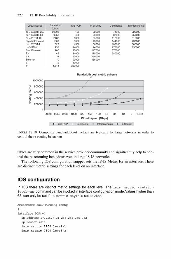
tables are very common in the service provider community and significantly help to con-trol the re-rerouting behaviour even in large IS-IS networks.
The following IOS configuration snippet sets the IS-IS Metric for an interface. Thereare distinct metric settings for each level on an interface.
IOS configurationIn IOS there are distinct metric settings for each level. The isis metric <metric>level-<n> command can be invoked in interface configur-ation mode.Values higher than63, can only be set if the metric-style is set to wide.
Amsterdam# show running-config
[ … ]
interface POS4/0
ip address 172.16.7.21 255.255.255.252
ip router isis
isis metric 1700 level-1
isis metric 2800 level-2
322 12. IP Reachability Information
Circuit Speed Bandwidth(Mbps)
Intra-POP In-country Continental Intercontinental
220000250000315000430000600000950000
7400087000
112000141000185000275000370000580000
220002600035000430005000074000
117000175000250000435000
oc-768/STM-256oc-192/STM-64oc-48/STM-16Gigabit Ethernetoc-12/STM-4oc-3/STM-1Fast EthernetT3E3EthernetE1T1
398089952248810006221551004534102
1,544
125400
130030004500
14000200003400060000
100000150000220000
Bandwidth cost metric scheme
0
200000
400000
600000
800000
1000000
39808 9952 2488 1000 622 155 100 45 34 10 2 1,544
Circuit speed (Mbps)
Ro
uti
ng
met
ric
Intra POP In-CountryContinental Intercontinental
FIGURE 12.10. Composite bandwidth/cost metrics are typically for large networks in order to control the re-routing behaviour
!
router isis
net 49.0001.0010.0100.1004.00
metric-style wide
!
[ … ]
The metric information can only be set if the metric style is set to “wide”. If you (forexample) unconfigure the metric style wide (metric-style narrow) and forget to changethe metric down to below 63, the system will log the following message and fallback toautomatic metric calculation:
IOS command outputUnconfiguring the metric-style wide back to metric-style narrow causes IOS todrop every static metrics at the interface level.
Amsterdam (config-router) #metric-style narrow
%Removing wide metrics also removes ‘isis metric 1700 level-1’
configured on POS4/0
%Removing wide metrics also removes ‘isis metric 2800 level-2’
configured on POS4/0
Below is a JUNOS configuration, which sets the IS-IS metrics on a given logical interface.
JUNOS configurationIn JUNOS all IS-IS related information is located under the protocols isis configura-tion branch. The routing metrics are properties of a given logical IS-IS interface.
hannes@New-York> show configuration
[ … ]
protocols {
isis {
interface so-7/0/0.0 {
level 1 metric 1700;
level 2 metric 2400;
}
interface lo0.0;
}
}
[ … ]
The JUNOS configuration interface accepts all values ranging from 0 to 16777215.However, if an IS or IP reachability needs to get packaged in old-style TLVs, then
New-style Topology (IS-Reach) Information 323

JUNOS simply clips those values to 63. The above configuration generates an LSP,which looks like the following using tcpdump:
Tcpdump outputJUNOS silently clips metrics bigger than 63 down to 63. In order to produce congruenttopologies between ISs supporting old or new-style TLVs JUNOS even clips the new-styleTLVs down to 63.
11:36:49.609255 OSI, IS-IS, length: 270
L2 LSP, hlen: 27, v: 1, pdu-v: 1, sys-id-len: 6 (0), max-area: 3 (0)
lsp-id: 2092.1113.4007.00-00, seq: 0x000006b2, lifetime: 1199s
chksum: 0xb2a6 (correct), PDU length: 270, Flags: [ L1L2 IS ]
[ … ]
IS Reachability TLV #2, length: 12
IsNotVirtual
IS Neighbor: 1921.6800.1004.00, Metric: 63, Internal
Extended IS Reachability TLV #22, length: 10
IS Neighbor: 1921.6800.1004.00, Metric: 63, no sub-TLVs present
IP Internal reachability TLV #128, length: 12
IPv4 prefix: 192.168.1.2/32, Distribution: up,
Metric: 63, Internal
Extended IPv4 Reachability TLV #135, length: 9
IPv4 prefix: 10.254.47.8/30, Distribution: up, Metric: 63
[ … ]
The Extended IS Reach TLV #22 was just the first outcome of the Traffic EngineeringExtensions. As the RFC 1195 Style IP reachability TLVs #128 and #130 also suffer fromthe same set of problems a new Extended IP Reachability TLV has been defined.
12.4 New-style Topology (IP-Reach) Information
The Extended IP Reachability TLV #135 collapses the two old-style IP reachabilityTLVs #128 and #130 together. Figure 12.11 shows the structure of the Extended IPReachability TLV #135. The first four bytes is the Metric field which is 32 bits in size.The reason why it is 32 bits wide and not 24 bits wide is to stay compatible to other rout-ing protocols like BGP and OSPF, which also have 32-bit metrics for their routing infor-mation. By picking a compatible metric size, the protocol designers made sure that theimported metric from these protocols does not get clipped. Next, there is the Header bytewhich consists of the Up/Down Bit, the Sub-TLV Indicator Bit, and 6 bits for storing theprefix length. The purpose of the Up/Down Bit will be explained in more detail inSection 12.6. The Sub-TLV Bit indicates if there are any further sub-TLVs stored afterthe prefix. As of writing this book, only three sub-TLVs have been defined. Most of themaddress a way to tag routes for administrative purposes. draft-martin-neal-policy-isis-admin-tags and draft-ietf-isis-wg-multi-topology specify the sub-TLVs 1, 2 and 117.
324 12. IP Reachability Information

Next follow 6 bits of prefix length. It would appear at first that since 2^6 � 64, 5 bitsshould be doing fine, but do not be misled. Although IP prefixes are 32 bits in size, thereare still 33 distinct prefix lengths, keeping in mind that the default route (0/0) is a uniqueprefix as well. So only the values 0 to 32 are valid for encoding the prefix length. Nextthere are 0 to 4 bytes holding the prefix information. The extended IP Reachability TLVallowed variable packaging of IP prefixes for the first time. Recall that the old-style TLVsalways consumed 12 bytes for the entire prefix, regardless of how many bits were redun-dant due to the network mask masking the bits out.
In the Extended IP Reachability TLV #135 the idea is to only encode the bytes that con-tain useful information. Consider Figure 12.12 where the example prefix 172.16.64/19 isencoded. The first question is: how many bits really contain information? To find that out,just map the prefix length to the grid shown in Figure 12.12. The /19 line goes through the
New-style Topology (IP-Reach) Information 325
TLV Type
TLV Length
metric
Prefix Length
Prefix
optional all-subTLVs Length
optional subTLV Type
optional subTLV Length
optional subTLV Value
metric
Prefix Length
Prefix
optional all-subTLVs Length
optional subTLV Type
optional subTLV Length
optional subTLV Value
135
U/D sub
Bytes
1
1
4
1
0�4
1
1
1�247
4
1
0�4
1
1
1�*
U/D sub
1
1
FIGURE 12.11. The Extended IP Reachability TLV #135 uses variable-length packaging of prefixinformation

3rd byte. So byte number 3 is the last byte that contains useful information. Byte 4 does notcontain anything useful – there are just zeros. Therefore, only three bytes need to be stored.So by looking at the prefix length a receiver knows how many bytes to decode before the next prefix starts in the TLV. If there are no further sub-TLVs (as indicated by the sub-TLV bit) and the length in the TLV Header indicates that there are still some prefixesleft, the receiving decoder starts to read out the same structure once again, starting with the4-byte metric value.
The beginning of this section indicated that both the Internal and the External IPReachability TLV got collapsed to TLV #135. However, there is no internal/external dif-ferentiation in the TLV anymore. Protocol engineers argue that prefixes are typicallyeither internal or external, but not both. Quite the contrary: if the same prefix is known asboth internal and external, there is something really broken in the network. Should arouting protocol support ugly corner cases? Probably not. However, there is another(non-obvious) reason why there is no further internal/external differentiation in the TLV.Henk Smit, one of the authors of RFC 3784, noted once on a posting to the ISIS-WGmailing list:
I have never really understood the need for both TLV128 and TLV130. This was also one of thereasons why we decided to not carry the I/E metric bit semantics forward into TLV135 (the new IPprefix TLV defined in the IS-IS TE extensions draft). The most important reason was of course thefact that we had no bits left, and did not want to spend another byte per prefix.
Routing software is typically not upgraded frequently. Therefore it is clear that theold-style and new-style TLVs need to coexist for quite a while. Simply because it is prac-tic-ally neither possible nor feasible to upgrade an IS-IS network with several thousandrouters on a flag day. Unfortunately RFC 3784 gives no guidance about how the old- andnew-style TLVs should interoperate, and therefore vendors have come up with schemesthat are specified nowhere, which is bad, as it by definition prevents clean, interoperablesolutions.
326 12. IP Reachability Information
Byte 1
172
32
Byte 2 Byte 3 Byte 4
241680
16 64
172.16.64/19
Prefix Length
19
FIGURE 12.12. Variable packaging means that only the significant bits (byte chunks) are stored

12.5 Old-, New-style Interworking Issues
Recent releases of IOS and JUNOS support both the old-style and the new-style behav-iour. However, the implementations came up with different default behaviours as to howthe old-style and the new-style TLVs are advertised.
IOS by default advertises only the old-style information. The old-, new-style gener-ation can be controlled using the metric-style <narrow|transition|wide>level <1|2|1–2> router configuration command.
IOS configurationIn IOS you can control generation of old- and new-style TLVs using the metric-style<narrow|transition|wide> [level-<1|2>] router configuration knob. If the optionallevel statement is omitted then the metric-style applies to both levels.
Amsterdam# show running-config
[ … ]
router isis
metric-style wide level-2
metric-style transition level-1
[ … ]
The metric-style commands controls what information that IOS is advertising, but alsoimplicitly what kind of information IS-IS accepts. If you set the metric style to wide,then IOS in turn also accepts wide TLVs from other routers. The behaviour is similar forthe narrow metric style. If IOS only generates “narrow” style TLVs then it also justaccepts narrow style TLVs from other routers. The metric-style transition sends both old-and new-style TLVs and accepts both. If you think that the plain narrow and wide modesare too restrictive for your network migration, then you can weaken the strictness by addingthe keyword transition to the metric-style configuration command. The fol-lowing IOS configuration sends new-style TLVs in the Level 2 but does accept both old- and new-style TLVs at receipt of LSPs.
IOS configurationIn IOS you can weaken the strict checking nature of non-matching TLVs (non-matchingmeans receipt of old-style TLVs if wide metrics are configured, and receipt of new-styleTLVs if narrow metrics are configured) through adding the transition statement after themetric-style configuration.
Amsterdam# show running-config
[ … ]
router isis
metric-style wide transition level-2
[ … ]
Old-, New-style Interworking Issues 327

JUNOS is more migration-friendly in that respect. First of all, JUNOS always acceptsboth old-style and new-style TLVs. If (for example) a prefix or IS reachability informationis present in both old- and new-style TLVs, then the new-style TLVs take precedence overthe old-style TLVs. This accept-everything behaviour can’t be changed. What can be con-trolled is what JUNOS advertises. By default, both old and new-style metrics are adver-tised. Considering the previous example, one could best describe the JUNOS behaviour in(IOS words) as metric-style transition. In JUNOS, suppression of the old-style TLVs can be enabled using the wide-metrics-only configuration com-mand which is located under the protocols isis configuration branch. Sorryfor the awkward wording, “suppression can be enabled” – this wording tries to emphasizethe default behaviour and how the behaviour can be changed.
JUNOS configurationIn JUNOS suppression of old-style TLVs can be enabled on a per-level basis through useof the wide-metrics-only keyword.
hannes@New-York> show configuration
[ … ]
protocols {
isis {
level 1 wide-metrics-only;
interface lo0.0;
interface so-0/0/0;
}
}
[ … ]
JUNOS can also suppress generation of the new-style TLVs, although this is almostnever used in practice. Everybody wants to leverage the broader metrics and additional func-tionality, which is encoded into the sub-TLVs that are found only in the new-style TLVs.Suppression of new-style TLVs is only available on an IS-IS global basis. It is not pos-sible to turn the new-style TLVs off on a per level basis. The following JUNOS configur-ation shows how to turn off generation of new-style TLVs on a router-global basis.
JUNOS configurationIn JUNOS suppression of new-style TLVs can be enabled on a router-global basis throughuse of the traffic-engineering disable keywords. The newstyle TLVs have beendefined in RFC 3784 as the first application of one of the new-style TLVs was conveyingTraffic Engineering related information.
hannes@New-York> show configuration[ … ]protocols {
isis {traffic-engineering disable;
328 12. IP Reachability Information
interface lo0.0;interface so-0/0/0;
}}[ … ]
In today’s networks there is a combination of the old- and new-style TLVs and both willco-exist for quite a while to come. Some of the original RFC 1195 old-style TLVs havebeen refined in order to support domain-wide prefix distribution, which is defined in RFC2966. RFC 2966 re-defines the IP Reachability TLVs #128, #130 and also loosens a fewrestrictions of the original old-style TLVs. The following section clarifies why tradingscalability versus optimal routing makes sense.
12.6 Domain-wide Prefix Distribution
The designers of IS-IS had scalability in mind during the drafting of the specification.There are several different places to look for scalability in IS-IS, and one is the way thatprefixes get leaked between levels. Before explaining how IS-IS does this, it is best to firstdescribe how OSPF, another link-state protocol, leaks routing information between OSPFareas. The assumption is a bit of familiarity with OSPF, enough to appreciate the differ-ences between the two protocols. Consider Figure 12.13 to see how OSPF leaks prefixesbetween areas. The sample topology was introduced in Chapter 1, “Introduction”, and isredesigned here as an OSPF network – the two networks almost look the same. The sig-nificant difference is that the borderline between the backbone and the non-backbone areasis in IS-IS on the link (for example, between Atlanta and New York) whereas in OSPF itis inside the Area Border Router (New York). There are three OSPF areas defined: thebackbone Area 0, and two leak Areas 47 and 11. Now, explore how routes are leakedthrough the OSPF domain. First, the Area Border Routers (New York, Washington DC)between Area 47 and the backbone transfer (or leak) an internal route from Area 47 to thebackbone. The two Area Border Routers re-package the internal route from a Type-1LSA to a Type-3 LSA (Step 1). LSAs are information carriers in OSPF, similar to LSPsin IS-IS. A side effect of re-packaging New York and Washington is also to replace the Router-ID in the LSA field by the router’s loopback IP address. Next, the route getspropagated through the backbone by means of the Type-3 LSA. Then the two Area BorderRouters between Area 0 and Area 11 (London, Frankfurt) take the route that was pack-aged in the Type-3 LSA and translate them into the Area 11 (Step 2). Again, the two AreaBorder Routers replace the originating Router-ID by their own Router-ID which is typi-cally the loopback address. Finally, all internal routes from Area 47 get propagatedthrough area 0 and all attached non-zero areas like Area 11. A similar flow of routes goesin the reverse direction: internal routes from Area 11 get re-packaged into the backboneArea 0 as Type-3 LSAs by the Area Border Routers London and Frankfurt (Step 3). Onthe left-hand side of Area 0 the two Area Border Routers New York and Washington pickup the Type-3 LSA and inject it into Area 47 (Step 4). Finally, all the areas see all routes.
This behaviour is exactly the problem with scaling in a plain-vanilla OSPF setup:Smaller routers in the non-zero area get overwhelmed by a massive amount of routes.
Domain-wide Prefix Distribution 329

OS
PF
Are
a 11
OS
PF
Are
a 47
OS
PF
Are
a 0
Bac
kbon
e
Pen
nsa
uke
n
Fra
nkf
urt
Lo
nd
on
Was
hin
gto
n
New
Yo
rk
Par
is
Am
ster
dam
Sto
ckh
olm
Vie
nn
aM
un
ich
Atl
anta
Mia
mi
San
Jo
se
San
Fra
n
12
34
12
43
FIG
UR
E12
.13.
OSP
F le
aks
all p
refix
es in
to a
ll ar
eas,
whi
ch is
one
of
OSP
Fs s
calin
g ha
rms
330

Domain-wide Prefix Distribution 331
Typically, leakage of all routes into the non-zero areas is not necessary. All that the non-zero area needs to know is the area internal routes and a default route that points to theArea Border Routers.
IS-IS has much better scaling properties in that respect. Consider Figure 12.14. Verymuch like OSPF, IS-IS passes on Level 1 information to Level 2. However, the otherdirection is by default blocked: Level 1 routers have to rely on a default route generatedby the L1L2 routers.
Flooding just a default route is clearly a very scalable approach; however, the use ofthe default route as the only routing information pointing towards the ATTached Level 2router is very unspecific information. Sometimes it is necessary to trade protocol scal-ability for optimality of traffic flow. The side effect of unspecific information can be sub-optimal routing, as shown in Figure 12.15. Traffic towards 192.168.1.13/32 gets attractedto the closest L1L2 router, which is Router Barcelona, due to a lower metric of thedefault-route 0/0 of 2000, although from a total routing metric perspective, sending the traf-fic straight to the L1L2 Router Milan would be more optimal. The sub-optimal path-costMadrid-Barcelona-Paris-Frankfurt is 22000. The more optimal path would be Madrid-Milan-Frankfurt with a composite path-cost of 11500. The use of unspecific routing-information makes IS-IS have a kind of “blind spot” and results in sub-optimal routing.
RFC 2966 lifts that strict requirement to pass just the default 0/0 route down to Level 1 andallows leaking of prefixes from Level 1 to Level 2. Additionally, RFC 2966 allows externalroutes to exist in Level 1, which was strictly forbidden according to RFC 1195. But allowingthe routes to flow from Level 2 to Level 1 is still not enough, as shown in Figure 12.16.
Suppose some router, located beyond Paris in Level 2 originates (among others) itsloopback IP address, either in the internal IP Reachability TLV #128 or the Extended IPReachability TLV #135. Barcelona re-distributes the 192.168.1.1/32 prefix into Level 1.The Level-1 LSP travels through Level 1 finally arriving at Milan. Milan does what everyL1L2 router has to do, and accepts unconditionally all Level-1 IP prefixes and injectsthem into Level 2. This creates a wonderful routing loop as from this point on nobody reallyknows where the route really did originate. Therefore a Marker Bit is needed to markroutes that have been marked as Leaked from Level 2 to Level 1. Additionally, all L1L2routers need to suppress prefixes where the Marker Bit is set and not propagate them fur-ther. The Marker Bit is called, in RFC 2966 terminology, the Up/Down Bit. The ExtendedIP Reachability TLV #135 has had support for the Up/Down Bit from the beginning.
The old (RFC 1195) style TLVs do not have support for the Up/Down Bit in the ori-ginal specification, because none of the original authors was aware that too much scal-ability could lead to a problem. RFC 2966 also redefines the MSB of the default-metricfor the two old-style IP Reachability TLVs #128 and #130. Per RFC 1195, the MSB ofthe default-metric was specified as Reserved and should therefore be set to zero. SeeFigure 12.17 and Figure 12.18 for the revised version of the old-style TLVs.
12.6.1 Leaking Level-2 Prefixes into Level 1In both IOS and JUNOS the default behaviour of IS-IS is RFC 1195 compliant and doesnot leak L2 prefixes from Level 2 to Level 1. When you want certain prefixes to leakthrough you have to explicitly configure that.

Are
a 49
.000
1Le
vel 2
-onl
yA
rea
49.0
200
Are
a49
.010
0
Pen
nsa
uke
n
Fra
nkf
urt
Lo
nd
on
Was
hin
gto
n
New
Yo
rk
Par
is
Am
ster
dam
Sto
ckh
olm
Vie
nn
aM
un
ich
Atl
anta
Mia
mi
San
Jo
se
San
Fra
n
1
3
1
3
0/0
0/0
0/0
0/0
FIG
UR
E12
.14.
IS-I
S su
ppre
sses
per
def
ault
Lev
el 2
rou
ting
info
rmat
ion
to L
e vel
1
332
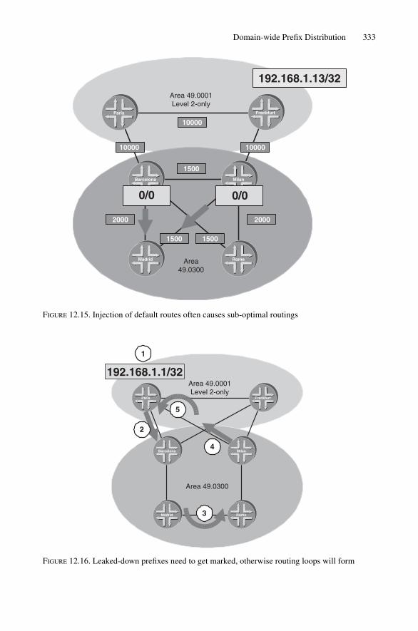
Domain-wide Prefix Distribution 333
Area 49.0001Level 2-only
Area49.0300
192.168.1.13/32
Barcelona Milan
RomeMadrid
FrankfurtParis
0/0 0/0
10000
1000010000
1500
20002000
1500 1500
FIGURE 12.15. Injection of default routes often causes sub-optimal routings
Area 49.0001Level 2-only
Area 49.0300
192.168.1.1/32
Barcelona Milan
RomeMadrid
FrankfurtParis
1
3
4
5
2
FIGURE 12.16. Leaked-down prefixes need to get marked, otherwise routing loops will form
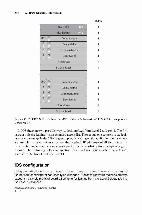
334 12. IP Reachability Information
TLV Type
TLV Length
IP Address
128
Bytes
1
1
1
1
1
1
4
4
N*12
Default MetricI/E0
Delay MetricS1
I/E0
Expense MetricS1
I/E0
Error MetricS1
I/E0
1
1
1
1
Default MetricI/E0
Delay MetricS1
I/E0
Expense MetricS1
I/E0
Error MetricS1
I/E0
SUbnet Mask
IP Address 4
4SUbnet Mask
U/D
U/D
FIGURE 12.17. RFC 2966 redefines the MSB of the default-metric of TLV #128 to support theUp/Down Bit
In IOS there are two possible ways to leak prefixes from Level 2 to Level 1. The firstone controls the leaking via an extended access list. The second one controls route leak-ing via a route-map. In the following examples, depending on the application, both methodsare used. For smaller networks, where the loopback IP addresses of all the routers in anetwork fall under a common network prefix, the access-list options is typically goodenough. The following IOS configuration leaks prefixes, which match the extendedaccess list 166 from Level 2 to Level 1.
IOS configurationUsing the redistribute isis ip level-2 into level-1 distribute-list commandthe network administrator can specify an extended IP access list which matches prefixesbased on a simple prefix/wildcard bit scheme for leaking from the Level 2 database intothe Level 1 database.
Amsterdam# show running-config
[ … ]
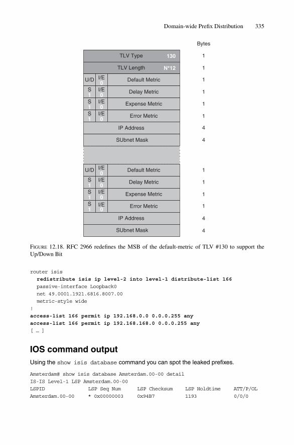
Domain-wide Prefix Distribution 335
TLV Type
TLV Length
IP Address
130
Bytes
1
1
1
1
1
1
4
4
N*12
Default MetricI/E0
Delay MetricS1
I/E0
Expense MetricS1
I/E0
Error MetricS1
I/E0
1
1
1
1
Default MetricI/E0
Delay MetricS1
I/E0
Expense MetricS1
I/E0
Error MetricS1
I/E0
SUbnet Mask
IP Address 4
4SUbnet Mask
U/D
U/D
FIGURE 12.18. RFC 2966 redefines the MSB of the default-metric of TLV #130 to support theUp/Down Bit
router isis
redistribute isis ip level-2 into level-1 distribute-list 166
passive-interface Loopback0
net 49.0001.1921.6816.8007.00
metric-style wide
!
access-list 166 permit ip 192.168.0.0 0.0.0.255 any
access-list 166 permit ip 192.168.168.0 0.0.0.255 any
[ … ]
IOS command outputUsing the show isis database command you can spot the leaked prefixes.
Amsterdam# show isis database Amsterdam.00-00 detail
IS-IS Level-1 LSP Amsterdam.00-00
LSPID LSP Seq Num LSP Checksum LSP Holdtime ATT/P/OL
Amsterdam.00-00 * 0x00000003 0x94B7 1193 0/0/0

336 12. IP Reachability Information
Area Address: 49.0001
NLPID: 0xCC
Hostname: Amsterdam
IP Address: 192.168.0.166
Metric: 0 IP 192.168.0.166/32
Metric: 10 IP 172.26.26.0/24
Metric: 10 IS-Extended London.00
Metric: 40 IP-Interarea 192.168.168.3/32
Metric: 30 IP-Interarea 192.168.168.4/32
Metric: 20 IP-Interarea 192.168.168.5/32
Metric: 20 IP-Interarea 192.168.168.6/32
Leaked IP prefixes are prepended via the keyword IP-Interarea that is printed ifthe Down Bit is found in one of the IP Reach TLVs.
In JUNOS policy processing there is always a default policy for each routing protocol.The default policy for IS-IS is to reject Level 2 routers from inclusion in the Level 1 data-base. If you want to change that behaviour then you need to write a policy and call itusing the export statement. This causes your Level 2 prefixes being evaluated beforethe default policy has chance to reject it.
JUNOS configurationIn JUNOS the most important task is writing the policy. The policy-statement leak-L2-to-L1 is a single term policy and it consists of three parts.The from portion reads like “if”and the keywords route-filter, protocol, level are ANDed together. That is, if theprefix is originated within protocol isis AND it is Level 2 AND it falls under the route-filter192.168.0/24 OR 192.168.168/24 THEN put it into the IS-IS Level 1 database.
[edit]
hannes@Frankfurt# show
[ … ]
protocols {
isis {
export leak-L2-to-L1;
}
}
policy-options {
policy-statement leak-L2-to-L1 {
from {
route-filter 192.168.0.0/24 orlonger;
route-filter 192.168.168.0/24 orlonger;
protocol isis;
level 2;
}
to {
protocol isis;
level 1;
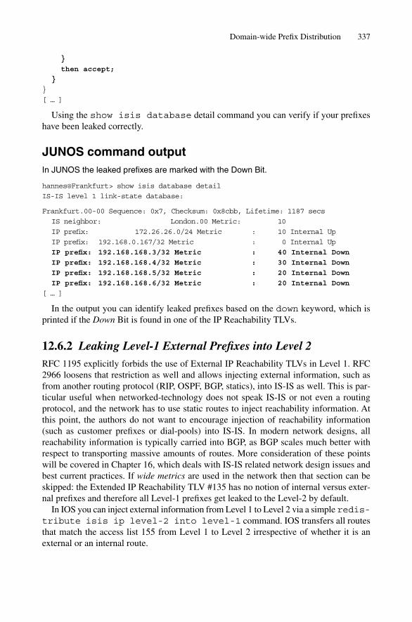
Domain-wide Prefix Distribution 337
}
then accept;
}
}
[ … ]
Using the show isis database detail command you can verify if your prefixeshave been leaked correctly.
JUNOS command outputIn JUNOS the leaked prefixes are marked with the Down Bit.
hannes@Frankfurt> show isis database detail
IS-IS level 1 link-state database:
Frankfurt.00-00 Sequence: 0x7, Checksum: 0x8cbb, Lifetime: 1187 secs
IS neighbor: London.00 Metric: 10
IP prefix: 172.26.26.0/24 Metric : 10 Internal Up
IP prefix: 192.168.0.167/32 Metric : 0 Internal Up
IP prefix: 192.168.168.3/32 Metric : 40 Internal Down
IP prefix: 192.168.168.4/32 Metric : 30 Internal Down
IP prefix: 192.168.168.5/32 Metric : 20 Internal Down
IP prefix: 192.168.168.6/32 Metric : 20 Internal Down
[ … ]
In the output you can identify leaked prefixes based on the down keyword, which isprinted if the Down Bit is found in one of the IP Reachability TLVs.
12.6.2 Leaking Level-1 External Prefixes into Level 2RFC 1195 explicitly forbids the use of External IP Reachability TLVs in Level 1. RFC2966 loosens that restriction as well and allows injecting external information, such asfrom another routing protocol (RIP, OSPF, BGP, statics), into IS-IS as well. This is par-ticular useful when networked-technology does not speak IS-IS or not even a routingprotocol, and the network has to use static routes to inject reachability information. Atthis point, the authors do not want to encourage injection of reachability information(such as customer prefixes or dial-pools) into IS-IS. In modern network designs, allreachability information is typically carried into BGP, as BGP scales much better withrespect to transporting massive amounts of routes. More consideration of these pointswill be covered in Chapter 16, which deals with IS-IS related network design issues andbest current practices. If wide metrics are used in the network then that section can beskipped: the Extended IP Reachability TLV #135 has no notion of internal versus exter-nal prefixes and therefore all Level-1 prefixes get leaked to the Level-2 by default.
In IOS you can inject external information from Level 1 to Level 2 via a simple redis-tribute isis ip level-2 into level-1 command. IOS transfers all routesthat match the access list 155 from Level 1 to Level 2 irrespective of whether it is anexternal or an internal route.

338 12. IP Reachability Information
IOS configurationLike the Level 2 to Level 1 redistribution in IOS you can specify a Level 1 to Level 2 redis-tribution list which points either to a route-map or to an extented access list.
Amsterdam# show running-config
[ … ]
router isis
redistribute isis ip level-2 into level-1 distribute-list 155
passive-interface Loopback0
net 49.0001.1921.6816.8007.00
metric-style wide
!
access-list 155 permit ip 10.0.0.0 0.0.255.255 any
[ … ]
JUNOS makes distinction between internal or external prefixes. If you want to injectexternal prefixes into the Level 2 of your network you need to match against the exter-nal keyword in your routing-policy.
JUNOS configurationThe default policy for leaking external prefixes from Level 1 to Level 2 is reject. If youwant to pre-empt the default policy you have to chain-in a policy called leak-ext-L1-to-L2 which catches all external Level 1 routes which match the 10.0/16 prefix.
[edit]
hannes@Frankfurt# show
[ … ]
protocols {
isis {
export leak-ext-L1-to-L2;
}
}
policy-options {
policy-statement leak-ext-L1-to-L2{
from {
route-filter 10.0.0.0/16 orlonger;
protocol isis;
external;
level 1;
}
to {
protocol isis;
level 2;
}
then accept;
}
}
[ … ]

Domain-wide Prefix Distribution 339
Notice the access lists and route filters that control the leakage between the two levels.It turned out that managing these access lists is a particular pain for large networks. Everytime you deploy new routers whose loopback IP addresses need to be leaked then youneed to touch all L1L2 routers in your network adjusting the access lists. Most ISPs mit-igated the problem by assigning blocks of loopback addresses to different POPs. Theaccess lists on the L1L2 routers therefore only need to be touched if a block in the POPis fully allocated. Another common practice is to filter based on a prefix length such as/32. Therefore only the loopback IP addresses get leaked – while this may seem as amodest approach for medium-sized networks it clearly does not scale for large networks.The largest networks in the world consist of about 7000–8000 IS-IS speaking routers.Leaking all 8000 prefixes at every L1L2 router may overwhelm the smaller routers in thePOP. So what is needed is a more selective way of picking off the /32s from Level 2.
12.6.3 Use of Admin Tags for Leaking PrefixesMost routing protocols support a tagging mechanism to enforce a route-redistributionpolicy. IS-IS has a similar extension formulated in draft-martin-neal-policy-isis-admin-tags.txt. The draft mentions two optional sub-TLVs to the Extended IP Reachability TLV#135 carrying 32-bit and 64-bit tags. Figure 12.19 shows how these administrative tagsare being used in large-scale deployments. First, each interesting /32 prefix (in the figureit is Quebec’s prefix 192.168.1.13/32) is tagged on the default leakage from Level 1 toLevel 2. Interesting typically means all those routers that rely on a proper IGP metric likepublic Internet routing. In our example, the Tag #200 is used for all Internet routers thatcarry Internet routes. The L1L2 routers Boston and Chicago attach the Tag #200 along withthe route. Next, those tagged prefixes travel through the Level-2. On the egress L1L2routers (Frankfurt and Paris) the leaking policy now gets very simple as all we have tolook for is Tag #200 to find out whether to leak the prefix or not. The policy needs to beconfigured only once and then all you have to do is properly tag the prefixes and yournetwork will act accordingly.
In the following two configurations you will see two configurations for IOS and twoconfigurations for JUNOS. The first of the two respective configurations does the taggingand the second one does the leakage based on the existence of a tag.
Applying admin tags is fairly simple in IOS. An admin tag is typically an interface prop-erty and can be set using the keyword isis tag <tag>.
IOS configurationIn IOS you set the Admin tag typically on the Loopback Interface. Using the show isisdatabase London.00-00 level-1 verbose you can verify if the Admin tag has beensuccessfully attached to your Loopback route.
London# show running-config
[ … ]
interface Loopback0
ip address 192.168.0.166 255.255.255.255
isis tag 200
!

340 12. IP Reachability Information
Area 49.0001Level 2-only
Area
49.
0300
Area
49.
0400
Pennsauken
Frankfurt
London
Washington
New York
Paris
Tag 200
Tag 200
Barcelona
Milan
Rome
Madrid
Montreal
Chicago
Boston
Quebec
192.168.1.13/32
192.168.1.13/32
�Tag 200
192.168.1.13/32
�Tag 200
FIGURE 12.19. Admin tags are a convenient way of implementing an AS-wide policy for leaking /32s
IOS command outputLondon#show isis database London.00-00 level-1 verbose
IS-IS Level-1 LSP London.00-00
LSPID LSP Seq Num LSP Checksum LSP Holdtime ATT/P/OL
London.00-00 * 0x00000010 0x574C 819 0/0/0
Area Address: 49.0001
NLPID: 0xCC
Hostname: London
IP Address: 192.168.0.166
Metric: 0 IP 192.168.0.166/32
Route Admin Tag: 200

Domain-wide Prefix Distribution 341
Metric: 10 IP 172.26.26.0/24
Metric: 10 IS-Extended London.00
[ … ]
The second IOS policy now needs to match against all previously tagged prefixes. Seethe example below, which uses a route-map for achieving that purpose.
IOS configurationTo match against the previously tagged prefixes you need to unconfigure the redistributeisis ip level-2 into level-1 distribute-list 166 command and use the redis-tribute isis ip level-2 into level-1 route-map command instead. This com-mands points to a route-map, which has far more fine-grained control than an access listwould offer.
London# show running-config
router isis
redistribute isis ip level-2 into level-1 route-map
leak-tagged-L2-to-L1
passive-interface Loopback0
net 49.0001.1921.6816.8007.00
metric-style wide
!
route-map leak-tagged-L2-to-L1 permit 10
match tag 200
!
[ … ]
The route-map leak-tagged-L2-to-L1 is fairly simple. It permits all prefixes,which carry the tag 200 and report it back to the IS-IS redistribution process for inclu-sion in the Level-1 database.
You can verify the results of your policy by using the show isis database <lsp-id> verbose command. The verbose modifier also displays the Admintags, which the detail modifier does not.
IOS command outputLondon#show isis database London.00-00 level-1 verbose
IS-IS Level-1 LSP London.00-00
LSPID LSP Seq Num LSP Checksum LSP Holdtime ATT/P/OL
London.00-00 * 0x0000000D 0x8140 797 0/0/0
Area Address: 49.0001
NLPID: 0xCC
Hostname: London
IP Address: 192.168.0.166

342 12. IP Reachability Information
Metric: 0 IP 192.168.0.166/32
Metric: 10 IP 172.26.26.0/24
Metric: 10 IS-Extended Frankfurt.00
Metric: 20 IP-Interarea 192.168.168.5/32
Route Admin Tag: 200
[ … ]
In JUNOS we need to perform the same two steps. First all the routers in the networkneed to tag all their loopback networks using the tag #200. This is achieved by applyingthe policy tag-lo0.
JUNOS configurationIn JUNOS the tagging is done once again via a policy. The policy tag-lo0 reads as: takeall IP addresses from your logical interface lo0.0 and apply an IS-IS tag #200 to it.
[edit]
hannes@Frankfurt# show
[ … ]
protocols {
isis {
export tag-lo0;
}
}
policy-options {
policy-statement tag-lo0 {
from {
interface lo0.0;
}
then {
accept;
tag 200;
}
}
}
[ … ]
You can verify if the tag has been correctly applied using the show isis databaseextensive output and spot the TLVs section of that output.
hannes@Frankfurt> show isis database Frankfurt extensive
IS-IS level 1 link-state database:
Frankfurt.00-00 Sequence: 0x5, Checksum: 0x47da, Lifetime: 1171 secs
[ … ]
TLVs:
Area address: 49.0001 (3)
Speaks: IP

Domain-wide Prefix Distribution 343
Speaks: IPv6
IP router id: 192.168.168.5
IP address: 192.168.168.5
Hostname: Frankfurt
[ … ]
IP extended prefix: 192.168.168.5/32 metric 0 up
6 bytes of subtlvs
Administrative tag 1: 200
IP extended prefix: 172.16.33.5/30 metric 0 up
No queued transmissions
If your policy is working correctly you should see the tag #200 applied to your loop-back IP prefix. The tag is encoded using a sub-TLV to the Extended IP Reach TLV #135.
Now if everything is tagged correctly we change our leak-L2-to-L1 policy to matchagainst the presence of Admin tags rather than specifying a list of cumbersome and error-prone route-filters.
JUNOS configurationThe old leak-L2-to-L1 policy is renamed to leak-tagged-L2-to-L1 – additionally thefrom route-filter statements are removed and the tag statement is inserted as pri-mary identifier for routes that need to get leaked.
[edit]
hannes@Frankfurt# show
[ … ]
protocols {
isis {
export leak-tagged-L2-to-L1;
}
}
policy-options {
policy-statement leak-tagged-L2-to-L1 {
from {
tag 200;
protocol isis;
level 2;
}
to {
protocol isis;
level 1;
}
then accept;
}
}
[ … ]
Using Admin tags for route leaking is a powerful tool that you will not like to miss inmedium-to large-sized networks. Also interoperability between IOS and JUNOS is

344 12. IP Reachability Information
mature now and there are no reasons not to deploy it. As with the introduction of com-munities for iBGP routing it takes some time to set up all the tagging policies but oncedone you will enjoy not needing to administer access lists any more.
12.7 Conclusion
The IP Reachability TLVs have been facing constant evolution and change. First intro-duced in RFC 1195, later redefined in RFC 2966 and today obsoleted by the traffic engin-eering drafts, a variety of TLVs conveying IP reachability information is found in today’sIS-IS networks. There is no indication that this evolution will stop and when looking atall these changes one thing remains certain: the process of change itself. The open natureof the Extended IP Reachability TLVs make sure that the protocols can and will be fur-ther extended. The Admin tag and multitopology drafts continue to further evolve the IP Reachability TLVs.

Comparing IS-IS based on the root specification ISO 10589 to how IS-IS is deployedtoday shows that almost none of the original TLVs are in use anymore. What still isalmost unchanged are the original frame formats and PDU headers, another proof thatIS-IS is an easily extended routing protocol.
In recent years many extensions for a variety of diverse applications have been speci-fied and then deployed. Those enhancements are sometimes of a very different nature,ranging from name resolution functions, which are aimed to ease operations and man-agement, to supporting new network address families like IPv6. There are even exten-sions that put “band-aids” on general protocol weaknesses like missing checksums incertain PDU types. Some go as far as to question the suitability of a single SPF calcula-tion operation for a joint IPv4 and IPv6 topology.
This chapter covers the major IS-IS protocol extensions that have not yet been cov-ered. It highlights recent enhancements, for example for IPv6, additional checksum pro-tection, stronger authentication, multitopology SPF and graceful restart capability.
13.1 Dynamic Hostnames
The entity to uniquely describe an IS-IS router in a given topology is the System-ID. TheSystem-ID is a 48-bit (6 byte) field that really does not fit in anywhere in the IP universe.This reveals two operational problems regarding the System-ID once deployed:
• It is hard to memorize• It is hard to translate (resolve) to a name
Consider the CLI output below. If a NOC engineer needs to verify if a certain adja-cency is up, they need to check lists and manually map the System-IDs to a router name.Luckily in our example the routers’ loopback addresses are mapped to the System-IDusing a binary coded decimal (BCD) scheme.
JUNOS command outputhannes@Frankfurt> show isis adjacency
Interface System L State Hold (secs) SNPA
so-0/0/0.0 1921.6800.1017 2 Up 25
so-0/2/0.0 1921.6800.1012 2 Up 26
345
13
IS-IS Extensions

so-1/0/0.0 1921.6800.1019 2 Up 22
so-1/1/0.0 1921.6800.1018 1 Up 20
so-1/2/0.0 1921.6800.1021 2 Up 22
so-2/0/0.0 1921.6800.1022 2 Up 24
so-2/1/0.0 1921.6800.1023 1 Up 26
[ … ]
It is often possible to make the router translate Network Layer addresses to namesusing the Domain Name System (DNS). While utilizing the DNS for IPv4 and IPv6addresses may be a viable solution, it is not for System-IDs. No DNS software today, norany client resolver at the router, supports translation for these 48-bit entities.
To get a name translation service up and running, network service providers started tomaintain mapping tables for name resolution.
In IOS you can manually configure those mapping tables using the clns host con-figuration command.
IOS configurationThe clns host configuration option translates names to a NSAP prefix. If you want touse it just for System-ID translation then enter the minimal NSAP (8-bytes) and set theArea-ID (first byte) and Selector Byte (last byte) to zero.
London#show running-config
[ … ]
clns host Pennsauken 00.1921.6800.1021.00
clns host New-York 00.1921.6800.1021.00
clns host Washington 00.1921.6800.1021.00
clns host Frankfurt 00.1921.6800.1021.00
clns host Paris 00.1921.6800.1021.00
[ … ]
In JUNOS you can manually configure static name to System-ID mappings using thestatic-host-mapping keyword under the system {} stanza:
JUNOS configurationhannes@Frankfurt> show configuration
system {
[ … ]
static-host-mapping {
Pennsauken sysid 1921.6800.1017;
London sysid 1921.6800.1012;
New-York sysid 1921.6800.1019;
Washington sysid 1921.6800.1021;
Paris sysid 1921.6800.1022;
}
}
[ … ]
346 13. IS-IS Extensions

Maintaining a mapping table on all of the routers is an easy thing if the network consistsjust of six routers like the example network does. However, over time it is very awkward todistribute mapping information each time a router is added, changed or removed. Relying onan external server like the DNS is not a viable choice either. If you troubleshoot your IS-ISnetwork because there is a problem, then there may be a situation where connectivity to thename resolution server is disrupted and you have to fall back to manual translation. The besttroubleshooting tool can be a problem if it does not work as expected when you need it most.
The ISIS-WG of the IETF found that the best place for a System-ID to name transla-tion service is actually the routing protocol itself. RFC 2763 describes a TLV to advertisehostnames along with a router’s LSP to distribute name to System-ID mapping informa-tion throughout a given level. The dynamic Hostname TLV is illustrated in Figure 13.1.The TLV is nothing but a freeform string that conveys the router’s hostname. Usually thehostname is one of the very first things initially configured on a router.
IOS configurationSetting of the hostname causes not only the prompt to change. Additionally the host-name is advertised using TLV #137.
London#show running-config
[ … ]
hostname London
!
JUNOS configurationIn JUNOS the hostname is set inside the system {} stanza using the hostname key-word.
hannes@Frankfurt> show configuration
system {
host-name Frankfurt;
[ … ]
}
Dynamic Hostnames 347
Type
Length
Hostname
137
Bytes
1
1
1–255
FIGURE 13.1. The dynamic Hostname TLV #137 is an envelope for transporting a simple ASCII string

As soon as you change the router’s hostname two things happen:
• The router prompt changes to use the new name• A new LSP is issued, and the Hostname TLV #137 contains the new name
Once a router receives an LSP and it detects the presence of a Hostname TLV #137, itstarts to maintain a hostname to System-ID cache. As soon as the router synchronizeswith one of its adjacent routers it learns all LSPs and, as a side benefit, all the knownSystem-ID to name mapping information is learned.
The tcpdump output shows the Washington LSP.
Tcpdump output11:36:45.587565 OSI, IS-IS, length: 405
L2 LSP, hlen: 27, v: 1, pdu-v: 1, sys-id-len: 6 (0), max-area: 3 (0)
lsp-id: 1921.8900.1021.00-00, seq: 0x000002fd, lifetime: 1198s
chksum: 0xe984 (correct), PDU length: 405, Flags: [ L1L2 IS ]
Area address(es) TLV #1, length: 4
Area address (length: 3): 49.0001
Protocols supported TLV #129, length: 2
NLPID(s): IPv4 (0xcc), IPv6 (0x8e)
Traffic Engineering Router ID TLV #134, length: 4
Traffic Engineering Router ID: 192.168.1.21
IPv4 Interface address(es) TLV #132, length: 4
IPv4 interface address: 192.168.1.21
Hostname TLV #137, length: 10
Hostname: Washington
Extended IS Reachability TLV #22, length: 75
IS Neighbor: 2092.1113.4007.00, Metric: 5, sub-TLVs present (64)
IPv4 interface address subTLV #6, length: 4, 172.16.33.6
IPv4 neighbor address subTLV #8, length: 4, 172.16.33.5
[ … ]
All receiving routers extract the first six bytes of the LSP-ID (System-ID) plus thecontent of the Hostname TLV #137 to populate the hostname cache.
You can display the hostname to System-ID mapping cache using the show isishostname command which is available both on IOS and JUNOS.
JUNOS command outputIn JUNOS you can display the System-ID to name cache using the show isis host-name command. The output shows if the mapping has been learnt by receipt of a Hostname TLV #137 (Type � Dynamic) or a static mapping defined under the system{} stanza (Type � Static). The local router always has its type set to Static.
348 13. IS-IS Extensions

hannes@Frankfurt> show isis hostname
IS-IS hostname database:
System ID Hostname Type
1921.6800.1017 Pennsauken Dynamic
1921.6800.1012 London Dynamic
1921.6800.1019 New-York Dynamic
1921.6800.1021 Washington Dynamic
1921.6800.1008 Frankfurt Static
1921.6800.1022 Paris Dynamic
1921.6800.1018 Stockholm Dynamic
1921.6800.1023 Munich Dynamic
1921.6800.1024 Vienna Dynamic
[ … ]
IOS command outputIOS lists additionally from which level it learned the hostname mappings. The asteriskindicates that the information originated locally.
London# show isis hostname
Level System ID Dynamic Hostname (notag)
* 1921.6800.1012 London
2 1921.6800.1017 Pennsauken
2 1921.6800.1019 New-York
2 1921.6800.1021 Washington
2 1921.6800.1008 Frankfurt
2 1921.6800.1022 Paris
1 1921.6800.1018 Stockholm
1 1921.6800.1023 Munich
1 1921.6800.1024 Vienna
If there is no hostname in the hostname cache, then most likely the router in questiondoes not originate the Hostname TLV as part of its link-state PDU.
Dynamic Hostnames 349
TABLE 13.1. The IS-IS Name Resolver replaces the System-ID by the cachedHostname string.
Hexadecimal representation Name representation
System-ID 1921.6800.1017 PennsaukenNode-ID 1921.6800.1017.00 Pennsauken.00LSP-ID 1921.6800.1017.00-00 Pennsauken.00-00
You can verify that the dynamic Hostname TLV is present by looking into the link-state database:
JUNOS command outputThe presence of a Hostname line in the show isis database extensive output showsthat the originating system did add the Hostname TLV.

hannes@Frankfurt> show isis database extensive
[ … ]
TLVs:
Area address: 49.0001 (3)
Speaks: IP, IPv6
IP router id: 192.168.1.18
IP address: 192.168.1.18
Hostname: Stockholm
IS neighbor: Frankfurt.00, Metric: 1
IP address: 172.16.33.45
[ … ]
IOS command outputLondon#show isis database verbose 1921.6800.1047.00-00
IS-IS Level-2 Link State Database:
LSPID LSP Seq Num LSP Checksum LSP Holdtime ATT/P/OL
1921.6800. * 0x00000040 0xD323 491 0/0/0
1047.00-00
Area Address: 49.0001
NLPID: 0x81
IS neighbor: Vienna.02, Metric: 63
[ … ]
The LSP shown in the IOS command output does not contain the Hostname TLV. Asit does not list any IP-related TLVs it may be that this is a CLNS-only router that is prob-ably running older software that does not support the Hostname TLV.
If the hostnames made their way into the hostname cache, then all IS-IS occurrences of theSystem-ID are replaced using their respective name. See Table 13.1 for how Pennsauken’sSystem, Node and LSP-IDs are represented using the new name resolution service.
Today IS-IS is one of the most convenient routing protocols. It aids the network engin-eer and troubleshooter by offering a kind of distributed name service. All of the IS-IS-related display functions like displaying adjacencies, examining the link-state databaseor logging functions make use of a System-ID to hostname translation cache and displaySystem-IDs, Node-IDs and LSP-IDs with their name rather than their hexadecimal rep-resentation.
The next extension to IS-IS will cover the authentication scheme of LSPs and theirimplementation.
350 13. IS-IS Extensions

13.2 Authenticating Routing Information
Authenticating routing protocol messages is a basic building block for every networksecurity strategy. Some people argue that authentication is pushing the envelope for IS-IS since all the messages run natively on Layer 2, which means that the protocol cannot be exposed to a remote attack from the Internet because there is simply no possi-bility for transporting a Layer-2 frame over the Layer-3 infrastructure. This is justanother way to say “you can’t route a frame”.
An attacker needs to have local, physical access to inject malicious information.Others argue that an additional barrier like authentication helps to keep out the errorsintroduced by, for example, unskilled NOC personnel. One application is that new IS-ISadjacencies cannot be created on an interface without knowing the password beforehand(this is just one example).
Both attacks and errors are cases where the use of authenticating PDUs makes sense.ISO 10589 defines a dedicated Authentication TLV for confirming the authenticity of thePDU. Figure 13.2 shows the structure of this TLV.
The Authentication TLV uses a field called Authentication Type to further indicatehow the password is encoded. Currently there are two encoding methods defined:
• Simple Text Authentication• HMAC-MD5
The left-hand side of Figure 13.2 shows the formatting of the TLV if Simple TextAuthentication is used. The password is a free-form string that can be between 1 and 254bytes in size. On the right-hand side there is the formatting of TLV #10 if HMAC-MD5Authentication is used. The size is fixed to 16 bytes and contains a MD5 sum of the entirepacket.
Authenticating Routing Information 351
Type
Length
Authentication Type
10
Bytes
1
1
1–254
Type
Length
Authentication Type
10
Bytes
1
1
16Plain Text Password HMAC-MD5 Password
1 1
17
171
FIGURE 13.2. The Authentication TLV #10 supports two different authentication types
13.2.1 Simple Text AuthenticationCode point 1 indicates simple text encoding of the password. Simple text encodingmeans that the password is encoded clear text. The following tcpdump output shows thatthe password contained in the IIH is transported clear text over the circuit.
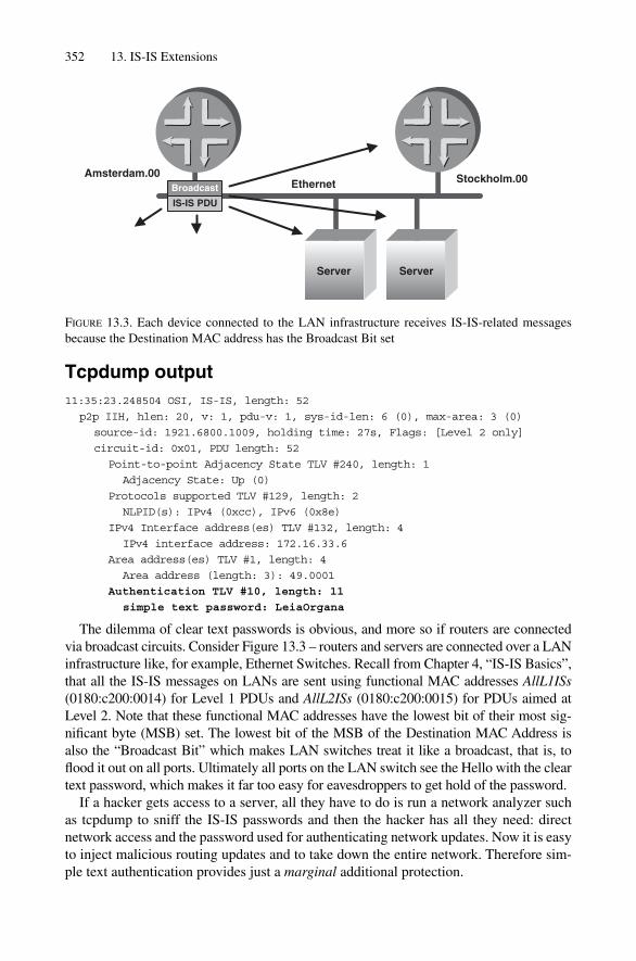
Tcpdump output11:35:23.248504 OSI, IS-IS, length: 52
p2p IIH, hlen: 20, v: 1, pdu-v: 1, sys-id-len: 6 (0), max-area: 3 (0)
source-id: 1921.6800.1009, holding time: 27s, Flags: [Level 2 only]
circuit-id: 0x01, PDU length: 52
Point-to-point Adjacency State TLV #240, length: 1
Adjacency State: Up (0)
Protocols supported TLV #129, length: 2
NLPID(s): IPv4 (0xcc), IPv6 (0x8e)
IPv4 Interface address(es) TLV #132, length: 4
IPv4 interface address: 172.16.33.6
Area address(es) TLV #1, length: 4
Area address (length: 3): 49.0001
Authentication TLV #10, length: 11
simple text password: LeiaOrgana
The dilemma of clear text passwords is obvious, and more so if routers are connected via broadcast circuits. Consider Figure 13.3 – routers and servers are connected over a LANinfrastructure like, for example, Ethernet Switches. Recall from Chapter 4, “IS-IS Basics”,that all the IS-IS messages on LANs are sent using functional MAC addresses AllL1ISs(0180:c200:0014) for Level 1 PDUs and AllL2ISs (0180:c200:0015) for PDUs aimed atLevel 2. Note that these functional MAC addresses have the lowest bit of their most sig-nificant byte (MSB) set. The lowest bit of the MSB of the Destination MAC Address is also the “Broadcast Bit” which makes LAN switches treat it like a broadcast, that is, toflood it out on all ports. Ultimately all ports on the LAN switch see the Hello with the cleartext password, which makes it far too easy for eavesdroppers to get hold of the password.
If a hacker gets access to a server, all they have to do is run a network analyzer such as tcpdump to sniff the IS-IS passwords and then the hacker has all they need: direct network access and the password used for authenticating network updates. Now it is easyto inject malicious routing updates and to take down the entire network. Therefore sim-ple text authentication provides just a marginal additional protection.
352 13. IS-IS Extensions
EthernetAmsterdam.00 Stockholm.00
IS-IS PDU
Broadcast
Server Server
FIGURE 13.3. Each device connected to the LAN infrastructure receives IS-IS-related messagesbecause the Destination MAC address has the Broadcast Bit set

13.2.2 HMAC-MD5 AuthenticationThe second encoding scheme is to use HMAC-MD5 hashes for securing the routingupdates. By using MD5 hashes the password does not travel clear text over the circuit.The HMAC-MD5 algorithm is documented in RFC 2104. It describes a one-way opera-tion to get a hash based on a bit field and a shared secret password. One-way functionmeans that, based on the hash and the bit field, the password cannot be reconstructed.
The authentication type for HMAC-MD5 is 54 and it is always using a fixed length of 16bytes. The following tcpdump output shows the 16-byte output of the hash. Note the TLVlength is 17 bytes because the first byte is reserved for the Authentication Type field.
Tcpdump output11:35:27.216425 OSI, IS-IS, length: 58
p2p IIH, hlen: 20, v: 1, pdu-v: 1, sys-id-len: 6 (0), max-area: 3 (0)
source-id: 1921.6800.1008, holding time: 27s, Flags: [Level 2 only]
circuit-id: 0x01, PDU length: 58
Point-to-point Adjacency State TLV #240, length: 1
Adjacency State: Up (0)
Protocols supported TLV #129, length: 2
NLPID(s): IPv4 (0xcc), IPv6 (0x8e)
IPv4 Interface address(es) TLV #132, length: 4
IPv4 interface address: 172.16.33.6
Area address(es) TLV #1, length: 4
Area address (length: 3): 49.0001
Authentication TLV #10, length: 17
HMAC-MD5 password: a933242e676df1275e323b648ab5e387
13.2.3 WeaknessesIn contrast to OSPF, IS-IS lacks cryptographic sequence numbers. This means IS-IS is notprone to so-called “replay attacks”. A replay attack means that an attacker is recordingmessages and replaying them at a later time in order to do something harmful. Usingreplay attacks it is quite easy to tear down an existing adjacency. Consider Figure 13.4.The hacker is constantly eavesdropping on a LAN and trying to record IS-IS IIH (Hello)messages in order to launch a replay attack. The first set of packets for adjacency estab-lishment are of particular interest. Consider the adjacency finite state machine mentionedin Figure 5.16 in Chapter 5, “Neighbour Discovery and Handshaking”. The idea is tocatch the message when the router is transitioning from the New to the Init state and toreplay that message at a later time.
Replaying a pre-recorded Hello that reports an Init state when the adjacency is alreadyestablished immediately moves it to the Down state. The receiver has no chance ofdetecting that this is an attack, as the IIH is properly authenticated.
Of course, a few packet exchanges after the attack, the adjacency would move again to theUp state as the periodic Hellos from both Amsterdam and Stockholm declare the adjacencyUp again. However, flapping adjacencies have a severe impact on the rest of the networkbecause new LSPs need to be generated; they need to get flooded throughout the network,SPF calculations need to be scheduled and finally the new FIB state needs to get propagated
Authenticating Routing Information 353

to the forwarding planes. Even if the router OS supports protection techniques like adja-cency hold down, the attack disrupts adjacencies for a period of time.
The way to prevent replay attacks is to add an element that is changed for every Hellothat is transmitted. By including a counter or Sequence Number (not to be confused withthe Sequence Number of the LSP) in the hashing, a replay attacker needs to wait 232
IS-IS packets in order to repeat an attack. Depending on the implementation-specificprotection timers, an attacker needs to wait more than a hundred years before he can suc-cessfully repeat a pre-recorded message. The assumption here is that a router does notgenerate more than one IS-IS PDU per second in order not to cycle too fast through thesequence space. This assumption is absolutely valid, as most of the IS-IS PDU types arerate-limited by the specification, like the LSP-min-generation-, CSNP- or Hello-Interval.
Up until now, no such sequencing mechanism has been deployed. Naiming Shen, adevelopment engineer with Redback, came up with a proposal for a new TLV on the IS-IS-WG list in the IETF. Figure 13.5 illustrates the proposed Sequence Number TLV. Thebasis structure of the TLV is to wrap a 32-bit number that is monotonically increasing.
Even if IS-IS is lacking in robustness against replay attacks, it is recommended to useMD5 authentication when deploying an IS-IS network. Most of the harm that can be donebased on replay attacks can be avoided by network design techniques, such as not usingbroadcast circuits in the core. Using replay attacks, an attacker can create some moderatestress in other parts of the network. After all, modern routers have enough processingpower to withstand such moderate attacks. So the most impacted place in the network will
354 13. IS-IS Extensions
EthernetAmsterdam.00 Stockholm.00
IIHAmsterdam
AllL1IS
Up
IIHStockholm
AllL1IS
Up
IIHStockholm
AllL1IS
Init
Server Server
FIGURE 13.4. An attacker replays a previously recorded message where the adjacency was in Initstate to tear it down
Type
Length
Sequence Number
241
Bytes
1
1
4
4
FIGURE 13.5. A monotonically increasing Sequence Number makes sure that the MD5-hash variesfor each transmitted Hello

be where the hacker is trying to cycle adjacencies through the Down state, which puts thehacker on the spot because he needs to have a direct link to that network.
However, not using authentication may put a hacker in the position to attack any sys-tem he wants to in the network and cause network-global stress that is not easily detectedin the first place. A nightmare for any NOC team.
13.2.4 Point-to-point InterfacesRunning authentication on point-to-point interfaces requires some explanation and caveats.First, point-to-point interfaces are different from LAN interfaces regarding their PDU types.Hello PDUs from the two levels need to share the point-to-point PDU type rather than hav-ing their own, like LAN IIHs do. Those constraints were further explained in Chapter 5,“Neighbour Discovery and Handshaking”. The fact that both levels need to share a PDUtype also has implications for authentication. Authentication in IS-IS always applies to theentire PDU. If the PDU type is shared between levels, then a single password needs to beshared for both levels as well. There is a potential for conflict in the configuration too, as (forexample) if two passwords (one for each level) are configured, then the router needs to makea decision. In IS-IS the rule set is simple: for Hello authentication, the Level-1 password isused. If there is no Level-1 password configured, then no Hello authentication is performed.
In the configuration example authentication for Hellos is turned on for both levelsusing different passwords.
JUNOS configurationThe authentication-key HanSolo is configured for Level 2 and LeiaOrgana for Level 1interface authentication. Because JUNOS scrambles all passwords, in the example wehave written down the password as commentary.
hannes@Frankfurt> show configuration
[ … ]
protocols {
isis {
[ … ]
interface so-0/1/2.0 {
level 2 {
hello-authentication-key “$9$dyVgJiHmTF/.P”; # HanSolo
hello-authentication-type simple; # SECRET-DATA
}
level 1 {
hello-authentication-key “$9$c-PSvLdVYoZjs25Q”; # LeiaOrgana
hello-authentication-type simple; # SECRET-DATA
}
}
interface lo0.0;
}
}
The tcpdump output reveals that only the Level-1 authentication key is used.
Authenticating Routing Information 355

Tcpdump outputFor point-to-point IIH authentication the Level-1 password is used.
20:10:22.699068 OSI, IS-IS, length: 61
point-to-point IIH, hlen: 20, v: 1, pdu-v: 1, sys-id-len: 6 (0),
max-area: 3 (0)
source-id: 1921.6800.1008, holding time: 27s, Flags: [Level 1, Level 2]
circuit-id: 0x01, PDU length: 61
[ … ]
Restart Signaling TLV #211, length: 3
Flags [none], Remaining holding time 0s
Authentication TLV #10, length: 11
simple text password: LeiaOrgana
Authentication is today imperative for securing routing protocols. Most authenticationmigrations have network-wide impact and require a strategy for gradually transitioningthe network.
13.2.5 Migration StrategyThere are three main authentication-related migration scenarios. All three migration sce-narios have one assumption in common: it is not possible to change the entire network inone “flag day” and there must not be any outage longer than (to cite a common example)a single adjacency reset.
13.2.5.1 General Decisions and Routing Software Selection
Before starting to implement authentication in an IS-IS, two questions need to beanswered:
• What IS-IS PDU types need to be authenticated?• What authentication type should be used?
The most likely answer is that HMAC-MD5 should be used as the authentication methodfor all PDU types. Unfortunately, there are some restrictions in older routing software.Particularly in IOS, IS-IS authentication has been neglected in the past. There are manycaveats as to what PDUs are authenticated and which authentication types are supportedin older releases of the IOS software. That has recently changed – as of 2004 there is fullauthentication support for all PDU types and both authentication methods. Full supporthas been available in versions equal or higher than IOS:
• 12.0(21)ST• 12.2(11)S• 12.0(22)S• 12.2(13)T• 12.2(14)S
356 13. IS-IS Extensions

If you do not have the choice, and are tied for some reason to a particularly IOS software release, then please proceed to Section 13.2.7, “Interoperability”, which willdiscuss an approach for making authentication work using older IOS releases.
Here are three authentication migration scenarios for an IS-IS network. The first of the three migration scenarios is the “Greenfield” approach: transition from an entirelyunauthenticated IS-IS network to an authenticated one.
13.2.5.2 Greenfield Migration
The Greenfield migration strategy uses asymmetric authentication. The term “asymmet-ric” refers to the ways how and if authentication information is sent and verified.Asymmetric authentication sends authentication information, but does not verify it. Thatway routers can be configured gradually to send their PDUs augmented with authentica-tion information. But they do not verify if the password is correct upon receipt. Once allthe routers in the network send the correct authentication information, the routers cangradually switch to symmetric authentication that does check to see if the suppliedauthentication string is correct. If it is not, then the PDU is discarded.
The second migration scenario covers the case of changing an authentication key in alive network.
13.2.5.3 Key Migration
Any good security policy can change passwords over time. A core network – which isadmittedly a cumbersome environment for any change – should change the authenticationon a periodic basis as well. For authentication key migration there are two possibilities:
• Asymmetrical authentication• Multiple key verification
Asymmetrical key verification is the panacea that works for all migration scenarios. Thismay even be a viable solution for the Greenfield scenario; however, for the key migrationmethod, the drawback is that a door is opened during the migration phase.
An implementation can decide to store many authentication keys on the router. One ofthose keys is used for sending authenticated PDUs. The remaining keys represent olderversions of the authentication string and each one is used against an incoming PDU. Thatway, network operators do not need to open the security gates for migrating keys.
Multiple key verification is clearly the preferred option to keep the security level of thenetwork intact. IOS supports keychains with their initial support for HMAC-MD5. JUNOS6.2 has no multiple keys available which means that as soon as JUNOS is introduced intothe network, the network must fall back to asymmetrical authentication schemes and hopethat during password migration there is no attack on the infrastructure (as slight as this vul-nerability might be, it is nonetheless real).
The last migration scenario is presented for completeness. It is not even discussed inthe IETF, but is still relevant.
13.2.5.4 Authentication Type Migration
Older IOS software only supports simple text authentication. For the time being this low-est common denominator (simple text authentication) is what both IOS and JUNOS has
Authenticating Routing Information 357

deployed. Network operators feel increasingly concerned about the non-existent securitythat simple text authentication provides and desperately want to switch to HMAC-MD5.
From a protocol perspective, nothing would prohibit the encoding of two versions ofthe Authentication TLV #10. The first one would carry the authentication key using MD5authentication and the second would carry the same authentication key using simple textauthentication. The biggest problem is that the deployed code only expects oneAuthentication TLV and there is little research into how the installed base of softwarewould react to multiple occurrences of Authentication TLVs. The IETF has so far notcoped with the problem, and typically refers inquiring parties to asymmetrical authenti-cation for solving problems of that kind.
In the next two sections there are practical examples of how to turn on IS-IS authenti-cation on IOS and JUNOS.
13.2.6 Running Authentication Using IOSIn Cisco IOS there are two general forms of authentication for IS-IS: interface authenti-cation and per-level authentication. Interface configuration applies to a specific interfaceonly, and authenticates IIH PDUs. Per-level authentication authenticates LSP and SNPPDUs. A pair of routers only needs to share the same password to successfully run inter-face authentication. Per-level authentication makes it necessary for all routers in a givenlevel to share the same password.
13.2.6.1 Per-interface Authentication
We use a simple networking scenario such as that illustrated in Figure 13.6 for the authen-tication examples. Two routers are connected via a Gigabit Ethernet interface. Pseudonodesuppression is turned on. The following configures an interface authentication betweenMadrid and Rome. All IIHs between the two routers on their Gigabit Ethernet interface are authenticated using MD5 authentication. Note that because the isis networkpoint-to-point keyword has been configured, only Level-1 passwords are sent.
In IOS you first need to define a key chain. Key chains are generic IOS functionsused for holding several authentication keys that can be configured for key rollover.Next, you need to configure the isis authentication mode and point to a keychain using the isis authentication key-chain command. Optionally, you can con-figure a level after the two commands. If you omit the level keyword then IOS takesthe key chain for authenticating both IS-IS levels.
358 13. IS-IS Extensions
EthernetMadrid.00 Rome.00
FIGURE 13.6. The simple setup will be used throughout the configuration examples

IOS configurationMadrid#show running-config
[ … ]
key chain MY-INTF-PASSWD
key 100
key-string 0 ManInTheM00n
[ … ]
interface GigabitEthernet4/0
ip address 172.16.34.5 255.255.255.252
ip router isis
isis authentication mode md5
isis authentication key-chain MY-INTF-PASSWD
isis network point-to-point
!
!
router isis
net 49.0300.1921.6800.3003.00
[ … ]
Now, you need to verify that your IIHs are properly authenticated. If you see debug messages like
IIH no change, use the same hmac value
then an Authentication TLV #10 containing a HMAC-MD5 value is applied to your outgoing IIHs.
IOS debug outputIf the router emits periodical messages like this after turning debug authentica-tion information on, then authenticated Hellos are sent.
Madrid#debug isis authentication information
IS-IS authentication information debugging is on
Madrid#
Nov 5 00:48:07.233: ISIS-AuthInfo: IIH no change, use the same hmac value
Nov 5 00:48:16.781: ISIS-AuthInfo: IIH no change, use the same hmac value
Nov 5 00:48:24.609: ISIS-AuthInfo: IIH no change, use the same hmac value
If your adjacency does not come up due to bogus authentication information then the outputof the debug isis authentication information reveals what the problem is.
IOS debug outputThe output of the debug isis authentication information command reveals if thereis a password mismatch.
Madrid#debug isis authentication information
IS-IS authentication information debugging is on
snail#
Nov 5 00:48:01.011: ISIS-AuthInfo: Packet failed the md5 check, 77 bytes, type 17
Authenticating Routing Information 359

Nov 5 00:48:09.095: ISIS-AuthInfo: Packet failed the md5 check, 77 bytes, type 17
Nov 5 00:48:17.059: ISIS-AuthInfo: Packet failed the md5 check, 77 bytes, type 17
From a configuration keyword point of view, the per-level authentication is very similar to the per-interface configuration. The only difference is in what PDU types areauthenticated.
13.2.6.2 Per-level Authentication
Applying per-level authentication authenticates all SNP and LSP PDUs on a per-levelbasis. The keywords are similar to the per-interface configuration.
The configuration example shows a simple text authentication for Level-1 SNP andLSP PDUs and a HMAC-MD5 authentication for Level-2 SNP and LSP PDUs.
IOS configurationMadrid#show running-config
[ … ]
key chain MY-LEVEL1-PASSWD
key 100
key-string 0 ObiWanhelpMEyouAREmyLastHope
!
key chain MY-LEVEL2-PASSWD
key 100
key-string 0 DoITorDONTdoitThereisnoTry
!
router isis
net 49.0300.1921.6800.3003.00
authentication mode text level-1
authentication mode md5 level-2
authentication key-chain MY-LEVEL1-PASSWD
authentication key-chain MY-LEVEL2-PASSWD
metric-style wide
passive-interface Loopback0
!
[ … ]
If an incoming LSP does not contain proper authentication then the output of thedebug isis authentication information commandwill report a Packetfailed the md5 checkmessage. If you receive PDUs containing no authenticationTLV at all then the debug output looks as follows:
IOS debug outputThe No auth TLV found debug message indicates that no Authentication TLV #10 ispresent in the PDU.
Madrid#debug isis authentication information
IS-IS authentication information debugging is on
360 13. IS-IS Extensions
Nov 5 01:50:25.776: ISIS-AuthInfo: No auth TLV found in received packet
Nov 5 01:50:25.848: ISIS-AuthInfo: No auth TLV found in received packet
Nov 5 01:50:25.900: ISIS-AuthInfo: No auth TLV found in received packet
13.2.6.3 Suppressing Authentication Checks
In the previous migration strategies there was a need to suppress authentication checking.In IOS suppression can be configured using the isis authentication send-only configuration keyword under the interface stanza to suppress IIH checking. Forsuppressing SNP and LSP checking the authentication send-only command isapplicable in the router isis stanza. Note that the command also suppresses gener-ation of errors in the log file. So you may run the risk that you mask a security hole.
The configuration of authentication on JUNOS is very similar to IOS.
13.2.7 Running Authentication Using JUNOSJUNOS also has two ways of authenticating IS-IS messages: per-interface and per-levelconfiguration. The basic difference is the set of PDU types authenticated. Per-interfaceauthentication authenticates interface Hellos.
13.2.7.1 Per-interface Authentication
Per-interface authentication is applied using the hello-authentication-key andhello-authentication-type configuration keyword in the protocols isisinterface level <*> stanza.
JUNOS configurationThe hello-authentication-key and hello-authentication-type configurationkeyword control authentication password and type for IIHs.
hannes@Stockholm> show configuration
[ … ]
protocols {
isis {
interface ge-4/0/0.0 {
point-to-point;
level 1 {
hello-authentication-key “$9$/tjmCu1SyK7NbApRSeW-dk.PQz6pu1”; #
ManInTheM00n
hello-authentication-type md5; # SECRET-DATA
}
}
interface lo0.0;
}
}
Authenticating Routing Information 361

13.2.7.2 Per-level Authentication
Unlike Cisco IOS, JUNOS authenticates all three PDU types by default. (Recall CiscoIOS only authenticates LSPs and SNPs). Because JUNOS per-level authentication alsoauthenticates IIHs, this is also a convenient way to do per-interface authentication on arouter with many interfaces. (Why only authenticate Hellos?)
JUNOS configurationThe authentication-key and authentication-type configuration keyword controlAuthentication-Key and Type for SNPs and LSPs.
hannes@Stockholm> show configuration
[ … ]
protocols {
isis {
level 1 {
authentication-key “$9$3qTB/CuRhrKWxvW”; #
ObiWanhelpMEyouAREmyLastHope
authentication-type md5; # SECRET-DATA
}
level 2 {
authentication-key “$9$fT390OReK8QFA0IcvMaZUHkPF39”; #
DoITorDONTdoitThereisnoTry
authentication-type md5; # SECRET-DATA
}
interface lo0.0;
}
}
If the adjacency does not come up, and you suspect an authentication problem, thenyou need to set up JUNOS traceoptions. Bogus authentications are logged with anerror flag.
JUNOS configurationIf you want to gather evidence that the authentication is broken you need to configure thetraceptions {} stanza
hannes@Stockholm> show configuration
[ … ]
protocols {
isis {
traceoptions {
file isis.log;
flag error;
}
}
}
362 13. IS-IS Extensions

Next you need to check the log file or set up a monitor job that displays any recentadditions to the file on the console.
JUNOS debug outputhannes@Stockholm> show log isis.log
Nov 5 04:16:02 trace_on: Tracing to “/var/log/isis.log” started
Nov 5 04:16:05 ERROR: LSP authentication failure
Nov 5 04:16:10 ERROR: LSP authentication failure
Nov 5 04:16:15 ERROR: LSP authentication failure
Nov 5 04:16:20 ERROR: LSP authentication failure
As you have seen in the migration examples, sometimes suppressing authenticationchecks is the only transition strategy you have got.
13.2.7.3 Suppressing Authentication Checks
JUNOS offers a single knob for suppressing all IS-IS-related authentication checks perrouting instance. So in JUNOS the provisions for asymmetric authentication are muchmore coarse than in IOS, which allows suppression of authentication on a per-interfaceand per-level basis.
JUNOS configurationThe no-authentication-check reverts the entire IS-IS process so as to not verify anyauthentication information.
hannes@Stockholm> show configuration
[ … ]
protocols {
isis {
no-authentication-check;
level 1 {
authentication-key “$9$3qTB/CuRhrKWxvW”; #
ObiWanhelpMEyouAREmyLastHope
authentication-type md5; # SECRET-DATA
}
level 2 {
authentication-key “$9$fT390OReK8QFA0IcvMaZUHkPF39”; #
DoITorDONTdoitThereisnoTry
authentication-type md5; # SECRET-DATA
}
interface lo0.0;
}
}
Unfortunately JUNOS does not feature chaining of several authentication keys. In orderto transition between authentication keys you need to utilize the no-authentication-check knob to turn authentication on and off during a single key transition.
Authenticating Routing Information 363

IS-IS was often the routing protocol of choice because of its high multivendor inter-operability, which is no surprise, since the specification was lean and well written.However, in the field of authentication, IOS and JUNOS were once not interoperable atall when it came to authentication. That has changed recently, and the next sectionexplores the remaining interoperability caveats.
13.2.8 InteroperabilityJUNOS supports MD5 and simple text authentication from the start, when the softwareshipped as JUNOS 3.0. Back in 1998, there was the conviction that authentication alwayshad to apply for all three PDU types (IIHs, SNPs, LSPs). That behaviour did not match theIOS behaviour at that time, which only authenticated LSPs. Optionally IOS also allowedconfiguration of interface authentication, but that bought authentication of only two out ofthe three PDU types involved. JUNOS authenticated symmetrically and expected authen-tication also on those PDU types that it sends as Authenticated PDUs. This led to a prob-lem, as IOS had no provision to authenticate SNPs – The only workaround was toconfigure no-authentication-check on JUNOS. Juniper Network’s engineerswere thinking of changing the behaviour, but that was not an option, because changing adefault behaviour is always a dangerous thing, and service provider customers are notvery happy if their vendor does change defaults very often. So with JUNOS 5.4, new knobswere introduced that suppress the all-PDU authentication styles. The three knobs are:
• no-hello-authentication
• no-csnp-authentication
• no-psnp-authentication
Originally, just a no-hello-authentication and no-snp-authenticationknob was planned, but it turned out that there is IOS software deployed in the field thatsupports authentication of CSNPs. In order to adapt to any environment, three knobswere released. An older-IOS compatible configuration turns on all three knobs whichfinally sends just authenticated LSPs and also just expects LSPs to be authenticated.
JUNOS configurationThe no-<*>-authentication knobs are used for adapting any sort of IOS behaviourfrom past releases.
hannes@Stockholm> show configuration
[ … ]
protocols {
isis {
level 1 {
authentication-key “$9$3qTB/CuRhrKWxvW”; #
ObiWanhelpMEyouAREmyLastHope
authentication-type md5; # SECRET-DATA
no-hello-authentication;
no-csnp-authentication;
364 13. IS-IS Extensions

no-psnp-authentication;
}
level 2 {
authentication-key “$9$fT390OReK8QFA0IcvMaZUHkPF39”; #
DoITorDONTdoitThereisnoTry
authentication-type md5; # SECRET-DATA
no-hello-authentication;
no-csnp-authentication;
no-psnp-authentication;
}
interface lo0.0;
}
}
Networking engineers often believe that because IS-IS is still a somewhat “secret”protocol and that this “security by obscurity” works well. Also, no known hacking toolsare able to handcraft IS-IS packets. But do not be misled! There are packet injection pro-grams around that can handcraft any IS-IS packet (it’s just that so far hackers have notused them to attack IS-IS). For example, the Nemesis Project is a toolset suite for craft-ing routing protocols of all kinds including IS-IS, RIP and OSPF. To learn more aboutNemesis check out the Nemesis homepage at http://sourceforge.net/projects/nemesis/.While tools like this may be a threat to networks, it is the authors’ opinion that they areuseful tools to harden and secure existing networks. Deploying MD5 authentication isimperative when running IS-IS. What still needs to be done on the IETF is adding crypto-graphic sequence numbers to be robust against all sort of attacks.
• A corrupted CSNP may trigger excessive PSNPs and LSPs because the receiver of thebroken CSNP thinks there are lots of unknown LSPs that it has to learn about. SeeChapter 8, “Synchronizing Databases” for the dynamics of SNPs requesting LSPs.
• About the worst thing that can happen is that the corrupt frame does not get detectedfor the time being. If routing control traffic gets corrupted, then it is also highly likelythat user payload traffic may be corrupted too. Most likely customer complaints aboutbad throughput will hit your desk.
In order to overcome this limitation of the base IS-IS protocol, the IETF has come upwith an optional Checksumming TLV which is defined in RFC 3358. The idea of theChecksum TLV is to protect IIHs and SNPs. Figure 13.7 shows the basic structure of the
Authenticating Routing Information 365
Type
Length
16 Bit “Fletcher” checksum
12
Bytes
1
1
2
2
FIGURE 13.7. The optional Checksum TLV #12 conveys an additional Fletcher Checksum that protects IIHs and SNPs
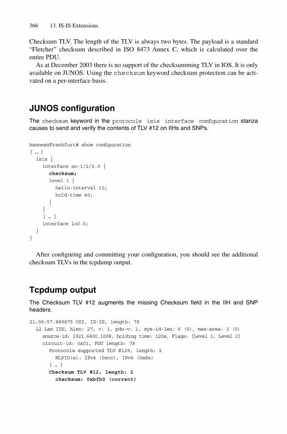
Checksum TLV. The length of the TLV is always two bytes. The payload is a standard“Fletcher” checksum described in ISO 8473 Annex C, which is calculated over the entire PDU.
As at December 2003 there is no support of the checksumming TLV in IOS. It is onlyavailable on JUNOS. Using the checksum keyword checksum protection can be acti-vated on a per-interface basis.
JUNOS configurationThe checksum keyword in the protocols isis interface configuration stanzacauses to send and verify the contents of TLV #12 on IIHs and SNPs.
hannes@Frankfurt# show configuration
[ … ]
isis {
interface so-1/2/0.0 {
checksum;
level 1 {
hello-interval 10;
hold-time 40;
}
}
[ … ]
interface lo0.0;
}
}
After configuring and committing your configuration, you should see the additionalchecksum TLVs in the tcpdump output.
Tcpdump outputThe Checksum TLV #12 augments the missing Checksum field in the IIH and SNP headers.
21:06:57.889875 OSI, IS-IS, length: 78
L2 Lan IIH, hlen: 27, v: 1, pdu-v: 1, sys-id-len: 6 (0), max-area: 3 (0)
source-id: 1921.6800.1008, holding time: 120s, Flags: [Level 1, Level 2]
circuit-id: 0x01, PDU length: 78
Protocols supported TLV #129, length: 2
NLPID(s): IPv4 (0xcc), IPv6 (0x8e)
[ … ]
Checksum TLV #12, length: 2
checksum: 0xbfb0 (correct)
366 13. IS-IS Extensions

21:17:30.950224 OSI, IS-IS, length: 135
L2 CSNP, hlen: 33, v: 1, pdu-v: 1, sys-id-len: 6 (0), max-area: 3 (0)
source-id: 0000.0000.0002.00, PDU length: 135
start lsp-id: 0000.0000.0000.00-00
end lsp-id:ffff.ffff.ffff.ff-ff
Checksum TLV #12, length: 2
checksum: 0x2d8f (correct)
LSP entries TLV #9, length: 96
lsp-id: 1921.6800.1017.00-00, seq: 0x000001a8, lifetime:
63177s, chksum: 0xebb1
13.3 Checksums for Non-LSP PDUs
Almost all kinds of networking protocols protect their message content with checksums.Protecting messages through a checksum follows a simple recipe. Both the sender andthe receiver of a message have to rely on a common way to build the checksum, thechecksum algorithm. Popular checksum algorithms are CRC16, CRC32 and, for IS-IS,the ISO X.233/ISO 8473-1 “Fletcher” checksum. Each of these checksum algorithmshas different properties. What they have in common is that all of them can detect at leastone bit error. While the primary purpose of checksums is to detect bit errors, some algo-rithms, for example, try additionally to balance the proportion of zeros and ones in amessage to help the transmission devices not to lose clock synchronization. Note that allmodern communication infrastructure devices have extra payload scramblers before put-ting the bit-stream on the wire, so higher layers do not need to care if the frame containsa healthy proportion of zeros and ones any longer.
This section focuses just on the error-detecting properties of checksum algorithms andwill not further discuss other applications like zero and one balancing. The checksumprocedure works very simply.
First, the field in the message where the checksum is stored needs to be initialized toa common value, typically zero. Next, the sender and the receiver need to agree what partof the message needs to be protected. Typically, it is the entire frame excluding Layer-2encapsulation like MAC addresses or PPP headers. In IS-IS the LSP checksum does notencompass the entire PDU. The checksumming starts at an offset of 12 bytes relative tothe beginning of the IS-IS common header. This was done to exclude fields like the LSPAge, which may be subject to local time drift.
Finally, the checksum is calculated and inserted at the previously zeroed position.The receiver needs to perform the checksum operation in a similar way: First, save the
received checksum for later comparison. Set the original checksum position to zero.Next, calculate the checksum based on the agreed parts of the frame with the same algo-rithms that is typically defined in the protocol’s specification. Finally, compare the self-calculated checksum to the previously saved original checksum that was received withthe frame. If the two checksums match, then pass the frame on for further processing. Ifthey do not match, discard the frame and increment a counter telling the operator that
Checksums for Non-LSP PDUs 367

there must be something wrong. Not protecting routing protocol messages via check-sums is a bad idea because it does not give the receiver a chance to differentiate betweengood and corrupted messages.
13.3.1 PDUs Missing Checksum?IS-IS uses a total of five different PDU types (actually, there are nine, but some share theformat like dedicated Level 1 and Level 2 PDUs). Take a look at those five PDU headersillustrated in Figure 13.8. Only one PDU type, the LSP, contains a Checksum field. Allthe other PDU types are not protected by a Checksum field.
Serious harm can result if a corrupt message is not recognized as such. Consider (forexample) an adjacency between two routers. Now suppose a few bits in the arrivingframe got flipped by (for example) a transmission problem. Depending on what TLVs arecorrupted, the adjacency could be at best torn down or, worst, corrupted information isconveyed, as these examples show:
An adjacency that is reportedly in the Up state could be perceived to be in the Down statedue to corruption of the Adjacency State TLV #240. The result is a broken adjacencywhich will trigger a new LSP which is flooded network-wide.
lsp-id: 1921.6800.1012.00-00, seq: 0x0000003c, lifetime: 64166s, chksum: 0x0e2b
lsp-id: 1921.6800.1019.00-00, seq: 0x000001a2, lifetime: 62579s, chksum: 0xba03
lsp-id: 1921.6800.1021.00-00, seq: 0x00000d31, lifetime: 63277s, chksum: 0x1dc4
lsp-id: 1921.6800.1008.00-00, seq: 0x00000124, lifetime: 61291s, chksum: 0xb30f
lsp-id: 1921.6800.1022.00-00, seq: 0x00000117, lifetime: 63277s, chksum: 0x5acf
The use of the Checksum TLV is optional. The only place where the specification isfirm is that as soon as a receiver supports the Checksum TLV and the checksum is cor-rupt, it must discard the frame. RFC 3358 also discusses the case of a “checksummingcollision”. The collision of checksum occurs if both HMAC-MD5 authentication andchecksumming is configured on an interface. HMAC-MD5 is nothing more than a verywide checksum under the inclusion of a shared secret. Which checksumming functionshould be prioritized? One of the rules of TLV encoding is that each TLV is independentof any other. In the authentication/checksumming case, the order does matter and wouldbe a violation to that requirement. Final consensus was either to suppress or set the valueof the Checksum TLV #12 to zero once the router knows that HMAC-MD5 authentica-tion needs to be added to PDU. This is an acceptable behaviour, and is the mindset ofmany network engineers that HMAC-MD5 is nothing but a big checksum that makes surethat multiple bit flips get detected, which conventional checksumming methods are notcapable of, so there is no problem there. A 128-bit checksum is simply stronger than a 16-bit one. The tcpdump output shows occurrence of both an Authentication TLV #10 and aChecksumming TLV #12 in an IIH message. Note that the contents of the ChecksumTLV are set to zero, which is an indication that the receiver does not need to attempt toverify it. Also, one interesting side effect of the Fletcher sum is that it can never be zero.Zero is therefore a clear indication of an exception.
368 13. IS-IS Extensions

369
Intr
a-do
mai
n R
outin
g P
roto
col D
iscr
imin
ator
Hea
der
Leng
th In
dica
tor
Ver
sion
/Pro
toco
l ID
Ext
ensi
on
0�83 1
ID L
engt
h
PD
U T
ype
R 0R 0
R 0
PD
U V
ersi
on
Res
erve
d
Max
imum
Are
a A
ddre
sses
6 (0
) 1
3 (0
)0
Res
erve
d
TLV
sec
tion
LA
N II
H P
DU
15, 1
627
circ
uit
type
1, 2
, 3
Sou
rce
ID
Hol
ding
Tim
e
PD
U L
engt
h
Prio
rity
R
Des
igna
ted
IS L
AN
-ID
Byt
es 1 1 1 1 1 1 1 1
0–14
67
1
ID L
engt
h (6
)
2 2 1
ID L
engt
h (6
) �
1
Intr
a-do
mai
n R
outin
g P
roto
col D
iscr
imin
ator
Hea
der
Leng
th In
dica
tor
Ver
sion
/Pro
toco
l ID
Ext
ensi
on
0�83 1
ID L
engt
h
PD
U T
ype
R 0R 0
R 0
PD
U V
ersi
on
Res
erve
d
Max
imum
Are
a A
ddre
sses
6 (0
) 1
3 (0
)0
TLV
sec
tion
18, 2
027
Rem
aini
ng L
ifetim
e
LSP
-ID
PD
U L
engt
h
Seq
uenc
e N
umbe
r
Ch
ecks
um
P
Byt
es 1 1 1 1 1 1 1 1
0–14
65
2 2
ID L
engt
h (6
) �
2
4 2 1A
TT
AT
TA
TT
AT
TO
LIS
Typ
e
LS
P P
DU
Intr
a-do
mai
n R
outin
g P
roto
col D
iscr
imin
ator
Hea
der
Leng
th In
dica
tor
Ver
sion
/Pro
toco
l ID
Ext
ensi
on
0�83 1
ID L
engt
h
PD
U T
ype
R 0R 0
R 0
PD
U V
ersi
on
Res
erve
d
Max
imum
Are
a A
ddre
sses
6 (0
) 1
3 (0
)0
TLV
sec
tion
24, 2
533
1,2,
3
Sou
rce
ID
Sta
rt L
SP
-ID
PD
U L
engt
h
End
LS
P-I
D
Byt
es 1 1 1 1 1 1 1 1
34–1
459
2
ID L
engt
h (6
) �
1
ID L
engt
h (6
) �
2
ID L
engt
h (6
) �
2
CS
NP
PD
U
Intr
a-do
mai
n R
outin
g P
roto
col D
iscr
imin
ator
Hea
der
Leng
th In
dica
tor
Ver
sion
/Pro
toco
l ID
Ext
ensi
on
0�83 1
ID L
engt
h
PD
U T
ype
R 0R 0
R 0
PD
U V
ersi
on
Res
erve
d
Max
imum
Are
a A
ddre
sses
6 (0
) 1
3 (0
)0
TLV
sec
tion
26, 2
717
1,2,
3
Sou
rce
ID
PD
U L
engt
h
Byt
es 1 1 1 1 1 1 1 1
18–1
475
2
ID L
engt
h (6
) �
1
PS
NP
PD
U
p2p
IIH
PD
U
Intr
a-do
mai
n R
outin
g P
roto
col D
iscr
imin
ator
Hea
der
Leng
th In
dica
tor
Ver
sion
/Pro
toco
l ID
Ext
ensi
on
0�83
Byt
es 1 1 1 1 1 1 1 1
1
ID L
engt
h
PD
U T
ype
R 0R 0
R 0
PD
U V
ersi
on
Res
erve
d
Max
imum
Are
a A
ddre
sses
6 (0
) 1
3 (0
)0
Res
erve
d
TLV
sec
tion
4–14
67
1720
circ
uit
type
1, 2
, 3
Sou
rce
ID
Hol
ding
Tim
e
PD
U L
engt
h
Loca
l circ
uit I
D
1
ID L
engt
h (6
) �
1
2 2 1
1, 2
, 3
FIG
UR
E13
.8. O
nly
the
LSP
PD
U is
pro
tect
ed b
y a
16-b
it C
heck
sum
fiel
d
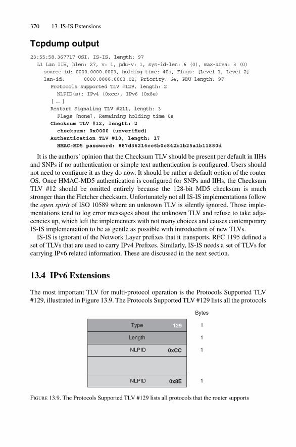
Tcpdump output23:55:58.367717 OSI, IS-IS, length: 97
L1 Lan IIH, hlen: 27, v: 1, pdu-v: 1, sys-id-len: 6 (0), max-area: 3 (0)
source-id: 0000.0000.0003, holding time: 40s, Flags: [Level 1, Level 2]
lan-id: 0000.0000.0003.02, Priority: 64, PDU length: 97
Protocols supported TLV #129, length: 2
NLPID(s): IPv4 (0xcc), IPv6 (0x8e)
[ … ]
Restart Signaling TLV #211, length: 3
Flags [none], Remaining holding time 0s
Checksum TLV #12, length: 2
checksum: 0x0000 (unverified)
Authentication TLV #10, length: 17
HMAC-MD5 password: 887d36216cc6b0c842b1b25a1b11880d
It is the authors’ opinion that the Checksum TLV should be present per default in IIHsand SNPs if no authentication or simple text authentication is configured. Users shouldnot need to configure it as they do now. It should be rather a default option of the routerOS. Once HMAC-MD5 authentication is configured for SNPs and IIHs, the ChecksumTLV #12 should be omitted entirely because the 128-bit MD5 checksum is muchstronger than the Fletcher checksum. Unfortunately not all IS-IS implementations followthe open spirit of ISO 10589 where an unknown TLV is silently ignored. Those imple-mentations tend to log error messages about the unknown TLV and refuse to take adja-cencies up, which left the implementers with not many choices and causes contemporaryIS-IS implementation to be as gentle as possible with introduction of new TLVs.
IS-IS is ignorant of the Network Layer prefixes that it transports. RFC 1195 defined aset of TLVs that are used to carry IPv4 Prefixes. Similarly, IS-IS needs a set of TLVs forcarrying IPv6 related information. These are discussed in the next section.
13.4 IPv6 Extensions
The most important TLV for multi-protocol operation is the Protocols Supported TLV#129, illustrated in Figure 13.9. The Protocols Supported TLV #129 lists all the protocols
370 13. IS-IS Extensions
Type
Length
NLPID
129
Bytes
1
1
1
NLPID
0xCC
0x8E 1
FIGURE 13.9. The Protocols Supported TLV #129 lists all protocols that the router supports

that an individual router supports. This TLV is found both in IIHs and LSPs. However, itwill be shown later that the inclusion of this TLV in the router’s LSP is a next to uselessexercise. The TLV contains a list of one-byte Network Layer Protocol ID (NLPID). Eachmajor Network Protocol has an NLPID assigned. In modern networks, you will mostlikely see the NLPID for IPv4 (� 0xCC), CLNS (� 0x81) or IPv6 (� 0x8E).
The IPv6 extensions are specified in draft-ietf-isis-ipv6-06. This Internet draft men-tions two TLVs which are aligned to their IPv4 counterparts, but just bigger in size. Anice touch of the IS-IS WG was to emphasize this similarity by picking a similar numberfor this TLV. Figure 13.10 illustrates the IPv6 Interface TLV #232. The TLV shares thesemantics of its little sibling, the IPv4 Address TLV #132 that is described in Chapter 5,“Neighbour Discovery and Handshaking”, in Figure 5.14.
The TLV holds one or several IPv6 addresses that are assigned on the sending inter-face. Hence the TLV is in multiples of 16 bytes. Typically only a single address, the IPv6link-local address, is conveyed.
Surprisingly, there is not much to configure in order to run IPv6 over IS-IS. Configuringan IPv6 Address and activating the IS-IS on that interface is enough. The router starts tosend IIHs that contain the IPv6 address on that interface, plus the IPv6 NLPID in theProtocol Supported TLV #129. The tcpdump output highlights the IPv6 additions.
Tcpdump output23:55:58.367717 OSI, IS-IS, length: 72
L1 Lan IIH, hlen: 27, v: 1, pdu-v: 1, sys-id-len: 6 (0), max-area: 3 (0)
source-id: 1921.6800.1008, holding time: 40s, Flags: [ L1L2 IS]
lan-id: 1921.6800.1008.02, Priority: 64, PDU length: 72
Protocols supported TLV #129, length: 2
NLPID(s): IPv4 (0xcc), IPv6 (0x8e)
[ … ]
IPv4 Interface address(es) TLV #132, length: 4
IPv4 interface address: 172.16.33.237
IPv6 Interface address(es) TLV #232, length: 16
IPv6 interface address: fe80::7777:69ff:fea0:8001
Area address(es) TLV #1, length: 4
Area address (length: 3): 49.0001
IPv6 Extensions 371
TLV Type
TLV Length
IP6 Address
232
Bytes
1
1
16
16
N * 16
IP6 Address
FIGURE 13.10. The IPv6 Interface Address #232 shares similar semantics to the IPv4 InterfaceAddress TLV #132

After the adjacency has formed, the router sends an updated LSP that contains the sec-ond IPv6 TLV that is defined in draft-ietf-isis-ipv6-06. Figure 13.11 illustrates the IPv6Reachability TLV. The TLV structure does seem similar and is borrowed from theExtended IPv4 Reachability TLV #135 explained in Figure 12.11 of Chapter 12, “IPReachability Information”.
TLV #236 is not as densely packed as TLV #135, but mostly because the maximumprefix length of an IPv6 prefix (128 bytes) could not be stuffed into a single byte alongwith the Flag bit information like the Up/Down bit and Sub-TLV Indicator bit. Tcpdumpoutput is shown below for the IPv6 Reachability TLV.
372 13. IS-IS Extensions
TLV Type
TLV Length
metric
Reserved
Prefix
optional all-subTLVs Length
optional subTLV Type
U/D
optional subTLV Length
optional subTLV Value
236
Bytes
1
1
4
1
0–16
1
1
1–246
E S
Prefix Length 1
1
metric
Reserved
Prefix
optional all-subTLVs Length
optional subTLV Type
U/D
optional subTLV Length
optional subTLV Value
4
1
0–16
1
1
1�*
E S
Prefix Length 1
1
FIGURE 13.11. The IPv6 Reachability TLV #236 took the Extended IPv4 Reachability TLV #135 as its blueprint

Tcpdump output01:15:43.232457 OSI, IS-IS, length: 182
L2 LSP, hlen: 27, v: 1, pdu-v: 1, sys-id-len: 6 (0), max-area: 3 (0)
lsp-id: 1921.6800.1008.00-00, seq: 0x00000033, lifetime: 65530s
chksum: 0xdde3 (correct), PDU length: 182, Flags: [ L1L2 IS ]
Area address(es) TLV #1, length: 4
Area address (length: 3): 49.0001
Protocols supported TLV #129, length: 2
NLPID(s): IPv4 (0xcc), IPv6 (0x8e)
[ … ]
IPv6 Reachability TLV #236, length: 22
IPv6 prefix: 2001:600::3/128, Distribution: up, Metric: 0, Internal,
no sub-TLVs
Extended IS Reachability TLV #22, length: 17
IS Neighbor: 1921.6800.1021.00, Metric: 250000, sub-TLVs present (6)
IPv4 interface address subTLV #6, length: 4, 172.16.33.237
In the following two sections there will be IPv6 configuration examples for both IOS andJUNOS.
13.4.1 IOS ConfigurationIn IOS the configuration is aligned to the IPv4 style: configuring an IP address and acti-vating IS-IS on the router is enough. For IPv6, the ipv6 address and the ipv6router isis configuration command include the IPv6 prefix in the router’s link-statedatabase and rebuilds the router’s LSP.
IOS configurationFor including an IPv6 Address in IS-IS all you need to do is configure the ipv6 routerisis keyword in the interface stanza.
London# show running-config
[ … ]
interface FastEthernet0/0
[ … ]
ipv6 address 2001:708:0:FF19::1/64
ipv6 router isis
!
Next you may want to verify that the prefix gets installed in the link-state database.
IOS command outputYou need to spot on IPv6 prefixes in the show isis database detail output.
IPv6 Extensions 373

London#show isis database detail
IS-IS Level-2 LSP
LSPID LSP LSP LSP Holdtime ATT/P/OL
Seq Num Checksum
Frankfurt.00-00 0x00000023 0xBA64 3555 0/0/0
Area Address: 49.0001
NLPID: 0xCC 0x8E
Router ID: 192.168.1.8
IP Address: 192.168.1.8
Hostname: Frankfurt
Metric: 250000 IS-Extended Washington.00
[ ... ]
Metric: 250000 IPv6 2001:708:0:FF19::2/64
[ ... ]
Finally you need to check if the route made its way in the IPv6 routing table.
IOS command outputThe show ipv6 route isis command limits the output to the isis installed routes.
London# show ipv6 route isis
IPv6 Routing Table - 9 entries
Codes: C - Connected, L - Local, S - Static, R - RIP, B - BGP
U - Per-user Static route
I1 - ISIS L1, I2 - ISIS L2, IA - ISIS interarea
O - OSPF intra, OI - OSPF inter, OE1 - OSPF ext 1, OE2 - OSPF ext 2
I2 2001:708:0:FF19::2/64 [115/13]
via FE80::2A0:A5FF:FE12:3398, GigabitEthernet2/0
[ … ]
The JUNOS configuration is similar, but simpler than the IOS configuration.
13.4.2 JUNOS ConfigurationIn JUNOS you need to configure two different stanzas. First, you need to configure theIPv6 address on a logical interface. Next, you add “family ISO” in order to be able toexchange IS-IS PDUs over that link. Finally, that interface is added to the interface listthat the IS-IS router builds when IS-IS is enabled.
JUNOS configurationAs soon as family inet6 is configured on a referenced iso interface JUNOS starts toannounce IPv6 Reachability Information.
374 13. IS-IS Extensions

hannes@Frankfurt> show configuration
[ … ]
interfaces {
so-1/2/0.0 {
unit 0 {
[ … ]
family iso;
family inet6 {
address 2001:708:0:FF19::2/64;
}
}
}
}
protocols {
isis {
interface so-0/1/2.0;
}
}
JUNOS command outputIP6 Reachability Information are indicated by the V6 prefix string of the show isisdatabase detail operational command output.
hannes@Frankfurt> show isis database detail
[ ... ]
Frankfurt.00-00 Sequence: 0x23, Checksum: 0xba64, Lifetime: 3433 secs
IS neighbor: Washington.00 Metric: 250000
[ … ]
V6 prefix: 2001:708:0:FF19::2/64 Metric: 0 Internal Up
Finally you can verify if the route was installed in the main routing table. You can dis-play the route using the show route table inet6.0 operational level command.
JUNOS command outputThe show route table inet6.0 protocol isis limits the output to isis installed routes.
hannes@Frankfurt> show route table inet6.0 protocol isis
inet6.0: 5 destinations, 5 routes (5 active, 0 holddown, 0 hidden)
� � Active Route, � � Last Active, * � Both
2001:708:0:FF19::2 *[IS-IS/18] 00:24:29, metric 15 > to
fe80::203:fdff:fec8:3c00 via so-1/2/0.0
So far it was assumed that the router is running IPv4 and IPv6 in dual mode. Dualmode is a term borrowed from RFC 1195 which means that two protocols share a singleSPF topology calculation and there is an assumption that the topology is congruent. Thatassumption may not be always correct, and there are scenarios where the dual assump-tion breaks even simple things like adjacency formation.
IPv6 Extensions 375
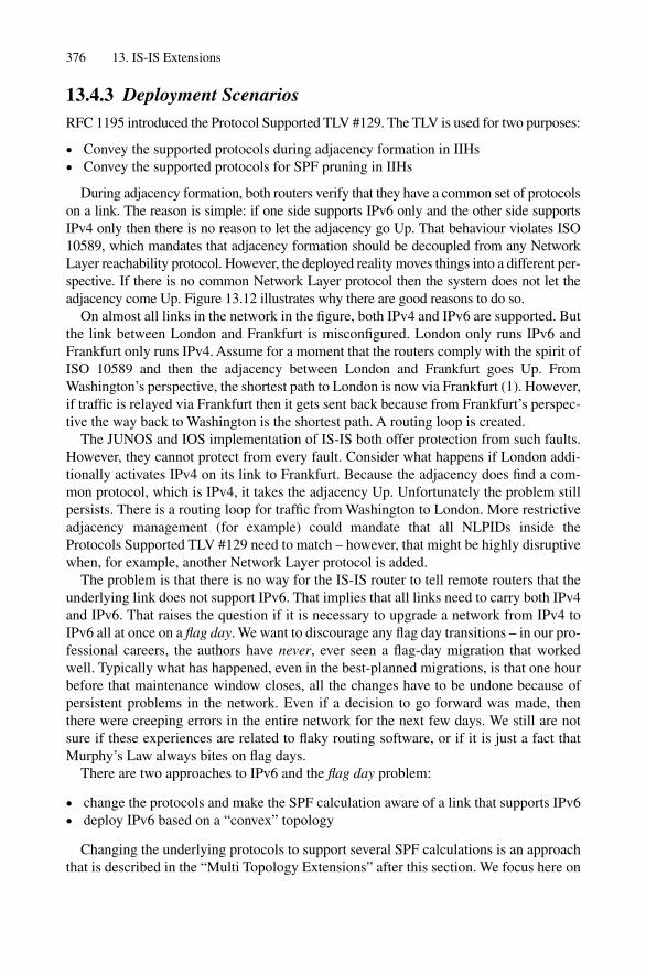
13.4.3 Deployment ScenariosRFC 1195 introduced the Protocol Supported TLV #129. The TLV is used for two purposes:
• Convey the supported protocols during adjacency formation in IIHs• Convey the supported protocols for SPF pruning in IIHs
During adjacency formation, both routers verify that they have a common set of protocolson a link. The reason is simple: if one side supports IPv6 only and the other side supportsIPv4 only then there is no reason to let the adjacency go Up. That behaviour violates ISO10589, which mandates that adjacency formation should be decoupled from any NetworkLayer reachability protocol. However, the deployed reality moves things into a different per-spective. If there is no common Network Layer protocol then the system does not let theadjacency come Up. Figure 13.12 illustrates why there are good reasons to do so.
On almost all links in the network in the figure, both IPv4 and IPv6 are supported. Butthe link between London and Frankfurt is misconfigured. London only runs IPv6 andFrankfurt only runs IPv4. Assume for a moment that the routers comply with the spirit ofISO 10589 and then the adjacency between London and Frankfurt goes Up. FromWashington’s perspective, the shortest path to London is now via Frankfurt (1). However,if traffic is relayed via Frankfurt then it gets sent back because from Frankfurt’s perspec-tive the way back to Washington is the shortest path. A routing loop is created.
The JUNOS and IOS implementation of IS-IS both offer protection from such faults.However, they cannot protect from every fault. Consider what happens if London addi-tionally activates IPv4 on its link to Frankfurt. Because the adjacency does find a com-mon protocol, which is IPv4, it takes the adjacency Up. Unfortunately the problem stillpersists. There is a routing loop for traffic from Washington to London. More restrictiveadjacency management (for example) could mandate that all NLPIDs inside theProtocols Supported TLV #129 need to match – however, that might be highly disruptivewhen, for example, another Network Layer protocol is added.
The problem is that there is no way for the IS-IS router to tell remote routers that theunderlying link does not support IPv6. That implies that all links need to carry both IPv4and IPv6. That raises the question if it is necessary to upgrade a network from IPv4 toIPv6 all at once on a flag day. We want to discourage any flag day transitions – in our pro-fessional careers, the authors have never, ever seen a flag-day migration that workedwell. Typically what has happened, even in the best-planned migrations, is that one hourbefore that maintenance window closes, all the changes have to be undone because ofpersistent problems in the network. Even if a decision to go forward was made, thenthere were creeping errors in the entire network for the next few days. We still are notsure if these experiences are related to flaky routing software, or if it is just a fact thatMurphy’s Law always bites on flag days.
There are two approaches to IPv6 and the flag day problem:
• change the protocols and make the SPF calculation aware of a link that supports IPv6• deploy IPv6 based on a “convex” topology
Changing the underlying protocols to support several SPF calculations is an approachthat is described in the “Multi Topology Extensions” after this section. We focus here on
376 13. IS-IS Extensions

IPv6 Extensions 377
oc192/STM-64
87000
oc12/STM-4
600000
oc192/STM-64
250000
oc768/STM-256
22000
oc768/STM-256
22000
oc48/STM-16
315000
oc48/STM-16
315000
oc192/STM-64
26000
6464
64
64
4
6
64
IPv4 only circuit
IPv6 only circuit
dual circuit
Pennsauken
Frankfurt
London
Washington
New York
Paris
4
664
64
64 64
64 64
6464
12
FIGURE 13.12. Protocol dependent adjacency management is imperative to avoid routing loops

deploying a convex style. Figure 13.13 illustrates how the IPv6 protocol is enabled infour steps. First, IPv6 is activated on the link between Pennsauken and London (1). Next,Pennsauken to New York is included (2). In the next two steps, (3) and (4), it is importantto include all nodes in expanding circles. Whenever there is a mesh, it needs to beincluded in the circle, otherwise it may be outside the best path.
Convex topologies are not always easy to compute (at least not for humans). In mod-erate to complex topologies it is recommended to let the router figure out where the linktopology can carry IPv6 and where it can not. A similar problem exists for IPv4 unicasttopologies. There are links and nodes that do support multicast processing and others that
378 13. IS-IS Extensions
New York London
Pennsauken
Frankfurt
London
Washington
New York
Paris
2
3
4
1
FIGURE 13.13. Convex topologies are required to rollout IPv6 in an incremental fashion

do not. For learning about the per-protocol processing capabilities of an IS-IS networkthe IETF has defined the multi topology extensions.
13.5 Multi Topology Extensions
The IGP evaluates all the paths in a single topology per level and selects by means of theSPF algorithm the best path among all the feasible paths. Topology discovery and SPFcalculation is carried out in a protocol neutral fashion because it is done at the OSI-RMLayer 2. If we load the topology with a certain protocol (for example IP) reachabilityinformation then the assumption is that the circuits that are supposed to provide reachability between routers can also carry the respective protocol. Since the first IP migra-tions, it was clear to the ISP community that a new paradigm was needed in order toavoid flag-day style migrations. What is necessary to get around the assumptions of RFC1195 is a proper per-address family orientation rather than a pure per-link orientation. Asa result of that, a per-protocol SPF calculation is required also, which means additionalCPU load. Today multiple SPF runs are easy to do because plenty of processing power isavailable on router control plane CPUs.
The multi topology extensions remodel existing TLVs and augment them with a so-called Topology ID. Each router in a given topology maintains its adjacencies and runsa per-topology SPF calculation. A topology is the set of joined nodes. The specificationmentions a list of well-known topologies, which are:
• IPv4 Unicast (#0)• In-Band Management (#1)• IPv6 Unicast (#2)• Multicast (#3)• IETF Consensus (#4-#3995)• Experimental (#3996-#4095)
We will focus here on the IPv4 and IPv6 Unicast topology. Consider Figure 13.14. The black lines indicate link membership in the IPv6 topology. And the gray line indi-cates membership to the IPv4 topology. Note that the two topologies are neither con-gruent nor convex.
Using regular TLVs, it would not be possible to build multiple topologies and run anSPF calculation based on it. The multi topology extensions first describe an extension tocarry the set of supported protocols in the Hello. Figure 13.15 shows the structure of theTopology Supported TLV #229, which is a vector of 12-bit wide Topology IDs. Afteractivating multi topology support on a link, it should carry all the topologies that theunderlying circuit is able to relay. The tcpdump output shows a IIH after multi topologyactivation.
IPv6 Extensions 379
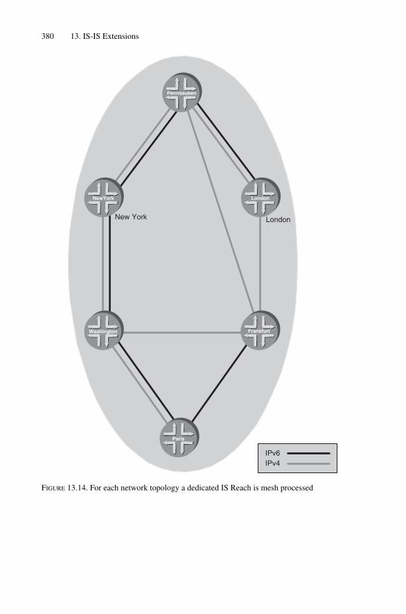
380 13. IS-IS Extensions
New York London
Pennsauken
Frankfurt
London
Washington
NewYork
Paris
IPv6IPv4
FIGURE 13.14. For each network topology a dedicated IS Reach is mesh processed
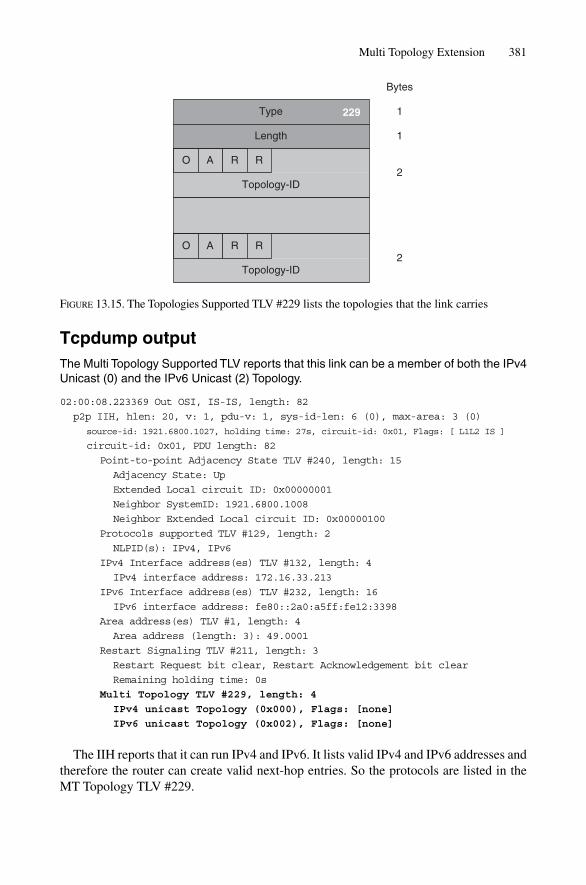
Multi Topology Extension 381
Tcpdump outputThe Multi Topology Supported TLV reports that this link can be a member of both the IPv4Unicast (0) and the IPv6 Unicast (2) Topology.
02:00:08.223369 Out OSI, IS-IS, length: 82
p2p IIH, hlen: 20, v: 1, pdu-v: 1, sys-id-len: 6 (0), max-area: 3 (0)
source-id: 1921.6800.1027, holding time: 27s, circuit-id: 0x01, Flags: [ L1L2 IS ]
circuit-id: 0x01, PDU length: 82
Point-to-point Adjacency State TLV #240, length: 15
Adjacency State: Up
Extended Local circuit ID: 0x00000001
Neighbor SystemID: 1921.6800.1008
Neighbor Extended Local circuit ID: 0x00000100
Protocols supported TLV #129, length: 2
NLPID(s): IPv4, IPv6
IPv4 Interface address(es) TLV #132, length: 4
IPv4 interface address: 172.16.33.213
IPv6 Interface address(es) TLV #232, length: 16
IPv6 interface address: fe80::2a0:a5ff:fe12:3398
Area address(es) TLV #1, length: 4
Area address (length: 3): 49.0001
Restart Signaling TLV #211, length: 3
Restart Request bit clear, Restart Acknowledgement bit clear
Remaining holding time: 0s
Multi Topology TLV #229, length: 4
IPv4 unicast Topology (0x000), Flags: [none]
IPv6 unicast Topology (0x002), Flags: [none]
The IIH reports that it can run IPv4 and IPv6. It lists valid IPv4 and IPv6 addresses andtherefore the router can create valid next-hop entries. So the protocols are listed in theMT Topology TLV #229.
Type
Length
229
Bytes
1
1
Topology-ID
O2
A R R
Topology-ID
O2
A R R
FIGURE 13.15. The Topologies Supported TLV #229 lists the topologies that the link carries

Each router advertises an adjacency for a common topology adjacency using the MultiTopology IS-Reachability TLV #222 (see Figure 13.16).
Tcpdump output02:10:39.192433 OSI, IS-IS, length: 151
L1 LSP, hlen: 27, v: 1, pdu-v: 1, sys-id-len: 6 (0), max-area: 3 (0)
lsp-id: 1921.6800.1027.00-00, seq: 0x00000050, lifetime: 1199s
chksum: 0x1477 (correct), PDU length: 151, Flags: [ L1L2 IS ]
[ ... ]
Multi Topology TLV #229, length: 4
IPv4 unicast Topology (0x000), Flags: [none]
IPv6 unicast Topology (0x002), Flags: [none]
Protocols supported TLV #129, length: 2
382 13. IS-IS Extensions
TLV Type
TLV Length
Neighbor ID
optional subTLV Value
222
Bytes
1
1
ID Length (6) � 1
3
1
1
1
1–240
Metric
subTLVs Length
optional subTLV Type
optional subTLV Length
Neighbor ID
optional subTLV Value
ID Length (6) � 1
3
1
1
1
1�*
Metric
subTLVs Length
optional subTLV Type
optional subTLV Length
Topology-ID2
Reserved
FIGURE 13.16. The Multi Topology IS Reachability TLV #222 is similar to the Extended IS Reachabil-ity TLV #22
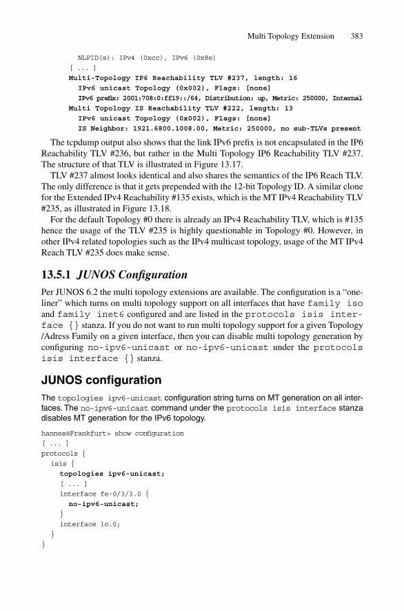
Multi Topology Extension 383
NLPID(s): IPv4 (0xcc), IPv6 (0x8e)
[ ... ]
Multi-Topology IP6 Reachability TLV #237, length: 16
IPv6 unicast Topology (0x002), Flags: [none]
IPv6 prefix: 2001:708:0:ff19::/64, Distribution: up, Metric: 250000, Internal
Multi Topology IS Reachability TLV #222, length: 13
IPv6 unicast Topology (0x002), Flags: [none]
IS Neighbor: 1921.6800.1008.00, Metric: 250000, no sub-TLVs present
The tcpdump output also shows that the link IPv6 prefix is not encapsulated in the IP6Reachability TLV #236, but rather in the Multi Topology IP6 Reachability TLV #237.The structure of that TLV is illustrated in Figure 13.17.
TLV #237 almost looks identical and also shares the semantics of the IP6 Reach TLV.The only difference is that it gets prepended with the 12-bit Topology ID. A similar clonefor the Extended IPv4 Reachability #135 exists, which is the MT IPv4 Reachability TLV#235, as illustrated in Figure 13.18.
For the default Topology #0 there is already an IPv4 Reachability TLV, which is #135hence the usage of the TLV #235 is highly questionable in Topology #0. However, inother IPv4 related topologies such as the IPv4 multicast topology, usage of the MT IPv4Reach TLV #235 does make sense.
13.5.1 JUNOS ConfigurationPer JUNOS 6.2 the multi topology extensions are available. The configuration is a “one-liner” which turns on multi topology support on all interfaces that have family isoand family inet6 configured and are listed in the protocols isis inter-face {} stanza. If you do not want to run multi topology support for a given Topology/Adress Family on a given interface, then you can disable multi topology generation byconfiguring no-ipv6-unicast or no-ipv6-unicast under the protocolsisis interface {} stanza.
JUNOS configurationThe topologies ipv6-unicast configuration string turns on MT generation on all inter-faces. The no-ipv6-unicast command under the protocols isis interface stanzadisables MT generation for the IPv6 topology.
hannes@Frankfurt> show configuration
[ ... ]
protocols {
isis {
topologies ipv6-unicast;
[ ... ]
interface fe-0/3/3.0 {
no-ipv6-unicast;
}
interface lo.0;
}
}
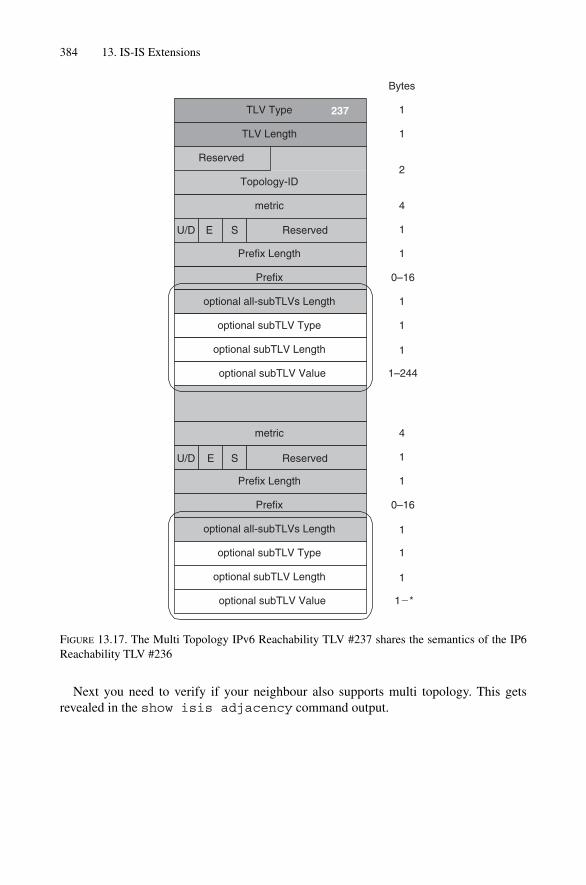
384 13. IS-IS Extensions
Next you need to verify if your neighbour also supports multi topology. This getsrevealed in the show isis adjacency command output.
TLV Type
TLV Length
metric
Reserved
Prefix
optional all-subTLVs Length
optional subTLV Type
U/D
optional subTLV Length
optional subTLV Value
237
Bytes
1
1
4
1
0–16
1
1
1–244
E S
Prefix Length 1
1
metric
Reserved
Prefix
optional all-subTLVs Length
optional subTLV Type
U/D
optional subTLV Length
optional subTLV Value
4
1
0–16
1
1
1�*
E S
Prefix Length 1
1
Topology-ID2
Reserved
FIGURE 13.17. The Multi Topology IPv6 Reachability TLV #237 shares the semantics of the IP6Reachability TLV #236

JUNOS command outputThe neighbour also supports multi topology for the IPv6 Unicast topology.
hannes@Frankfurt> show isis adjacency detail
[ … ]
London
Interface: so-1/2/0.0, Level: 2, State: Up, Expires in 23 secs
Priority: 0, Up/Down transitions: 11, Last transition: 00:24:12 ago
Circuit type: 3, Speaks: IP, IPv6
Topologies: Unicast, IPV6-Unicast
Restart capable: Yes
IP addresses: 172.16.33.29
IPv6 addresses: fe80::203:fdff:fec8:3c00
[ … ]
Multi Topology Extension 385
TLV Type
TLV Length
metric
Prefix Length
Prefix
optional all-subTLVs Length
optional subTLV Type
optional subTLV Length
optional subTLV Value
metric
Prefix Length
Prefix
optional all-subTLVs Length
optional subTLV Type
optional subTLV Length
optional subTLV Value
135
U/D sub
Bytes
1
1
4
1
0–4
1
1
1–245
4
1
0–4
1
1
1�*
U/D sub
1
1
Topology-ID2
Reserved
FIGURE 13.18. The Multi Topology IPv4 Reachability TLV #235 shares the semantics of theExtended IP Reachability TLV #135

386 13. IS-IS Extensions
The router has now received LSPs from neighbouring routers and processed them in aper-protocol SPF calculation. The output of all the show isis spf <*> commandshas changed. It now displays the statistics and results on a per-topology breakdown.
JUNOS command outputThe output of the show isis spf log command encompasses results for each topology.
hannes@Frankfurt> show isis spf log
IS-IS level 2 SPF log:
Start time Elapsed (secs) Count Reason
Fri Nov 7 01:58:29 0.000120 1 Updated LSP Paris.00-00
Fri Nov 7 01:58:33 0.000141 1 Updated LSP Frankfurt. 00-00
Fri Nov 7 01:58:38 0.000118 1 Updated LSP London.00-00
Fri Nov 7 01:59:54 0.000114 1 Updated LSP London.00-00
Fri Nov 7 01:59:59 0.000219 2 Lost adjacency London on so-1/2/0.0
Fri Nov 7 02:45:22 0.000084 1 Reconfig
IPV6 Unicast IS-IS level 2 SPF log:
Start time Elapsed (secs) Count Reason
Fri Nov 7 01:58:15 0.000066 7 Lost adjacency Pennsauken on so-7/0/0.0
Fri Nov 7 01:58:16 0.000095 2 Updated LSP Frankfurt. 00-00
Fri Nov 7 01:58:19 0.000098 1 Lost adjacency London on so-1/2/0.0
Fri Nov 7 01:59:54 0.000084 1 Updated LSP London.00-00
Fri Nov 7 02:23:46 0.000202 1 Periodic SPF
Fri Nov 7 02:34:45 0.000113 1 Reconfig
Fri Nov 7 02:45:22 0.000267 1 Reconfig
The configuration in IOS is equally simple.
13.5.2 IOS ConfigurationIOS now supports per-address family configuration. By configuring the multi-topology command under the address-family ipv6 stanza, multi topologysupport is turned on all interfaces that have the ipv6 router isis command listed.
IOS configurationLondon# show running-config
[ … ]
router isis
net 49.0001.1921.6800.1012.00
metric-style wide
passive-interface Loopback0
!
address-family ipv6
multi-topology
exit-address-family
!

Multi Topology Extension 387
Next you may want to verify that the peer supports multi topologies as well. Similar tothe JUNOS example, in IOS the show clns neighbors detail command yourneighbour states.
IOS command outputLondon# show clns neighbors detail
System Id Interface SNPA State Holdtime Type Protocol
Frankfurt POS2/0 PPP Up 25 L2 M-ISIS
Area Address(es): 49.0001
IP Address(es): 172.16.33.213*
IPv6 Address(es): FE80::2A0:A5FF:FE12:3398
Uptime: 00:13:42
NSF capable
Topology: IPv4, IPv6
Finally, you want to check how the processing of the IPv6 topology went. You can see thelog for the IPv6 MT Topology using the show isis ipv6 spf-log command.
IOS command outputThe show isis ipv6 spf-log command shows the SPF duration and reason for thelast calculations based on the IPv6 Unicast Topology.
London#show isis ipv6 spf-log
IPv6 level 2 SPF log
When Duration Nodes Count First trigger LSP Triggers
01:03:10 8 6 3 Frankfurt.00-00 NEWADJ DELADJ LVCONTENT
00:53:03 4 6 1 PERIODIC
00:52:49 5 1 2 London.00-00 DELADJ TLVCODE
00:52:34 4 6 2 London.00-00 NEWADJ TLVCODE
00:38:01 4 6 1 PERIODIC
00:28:24 4 6 1 Frankfurt.00-00 TLVCODE
00:22:57 4 6 1 PERIODIC
00:17:46 4 2 2 London.00-00 DELADJ TLVCODE
00:07:54 4 1 1 PERIODIC
13.5.3 Summary and ConclusionBecause of the stringent requirements of RFC 1195, which requires that all routers support all Network Layer protocols, it is hard to deploy IPv6 (for example) increment-ally. Convex migration schemes help to avoid routing loops during a network rollout.However, if there is mis-configuration then it is relatively easy to break a multi protocolenvironment in IS-IS. For that purpose, the IS-IS WG defined four additional TLVs thatmake each router build distinct topologies and perform a per Network Layer protocolSPF calculation. Multi topologies are a viable solution for deploying IPv6 incrementally

388 13. IS-IS Extensions
in the network, however, there is serious concern in the Service Provider community asto whether this complexity is necessary at all.
Most service providers have MPLS as the uniform transport vehicle, and MPLS isalready deployed in their networks. The idea is that the inner core topology runs on IPv4only and IPv6 Reachability Information is exchanged via BGP. BGP uses IPv4 to resolvethe next-hops and then traffic is relayed between a pair of BGP speakers using the MPLSmagic carpet. It is the authors’ opinion that if there is a possibility to re-use that MPLSmagic carpet, then there should be serious consideration whether an IPv6 control planeis required, necessary and worth the hassle.
13.6 Graceful Restart
The Internet is about to become the new public infrastructure. When the Internet willreplace today’s communication infrastructure is not as easy to predict. Common sensesays that you can pull the plug when the new infrastructure is better, faster and moreresilient than the old infrastructure. However, especially in terms of availability and soft-ware stability, IP switching platforms in the past lacked the resiliency and redundancy ofthe old infrastructure, like TDM multiplex networks and voice switches. Typically it isthe software that makes systems fail (assuming that the hardware designers have done their job well). When it comes to software, TDM multiplexers do not expose any weak-nesses due to their almost static configuration and so naturally avoiding any complex signalling software. On the other hand, voice switches have to rely on signalling proto-cols like SS7. Unfortunately, stability and “feature velocity” negatively impact eachother. It is relatively easy to freeze code and do some bug fixing in order to get to stablesignalling code and release the stable code in the hope that it does not break in the livenetwork. In a fast progressing world like the IP world, that approach is not feasiblebecause there will be always further enhancements/bug fixes to the base protocol.Modern software release models apply careful testing to the code base before it isreleased to the public. However, it turned out that there is a no more brutal reality-checkto verify if the code works than exposing it to the live Internet. Furthermore, the supportteams of the vendors had to be very responsive to fix any kind of problem really fast. Dueto the 24 � 7 nature of the Internet (non-business hours traffic is just 70 per cent of thepeak traffic during business hours) almost no maintenance window can be established.The necessary software upgrades are really painful for the users and operators, as a soft-ware upgrade always means about 60–180 seconds outage until the entire router complex(control plane and forwarding plane) is rebooted. A reboot of a routing node results in achanged topology. This topology change will have a negative impact on other routers,entailing AS-global SPF runs, BGP route flaps and subsequent route damping by externalBGP peering partners.
Modern routers are based upon a clear separation between the control plane and forwarding planes. The two entities can work independently from each other for a shortperiod of time. For example, the forwarding plane can easily keep forwarding state whilethe control plane (in Cisco, it is the Route-Processor; Juniper Networks calls it theRouting Engine) is rebooting. Keeping forwarding state means that the forwarding plane

Graceful Restart 389
forwards packets based on the last good routing information, effectively freezing the for-warding table. The control plane can next reboot, while the forwarding engine is stillpassing traffic.
The trouble starts when the control processor is coming up again. Because it justrebooted, it does not have any state knowledge of its adjacencies nor does it have anytopological insight (that is, the link-state database is empty). If a router is in that state andit generates an IIH and does not demonstrate that it has achieved 3-way state by listingits neighbour’s adjacency state or SNPA (for more on adjacency management seeChapter 5, “Neighbour Discovery and Handshaking”), then the adjacency will be imme-diately disrupted and global SPF recalculation will occur.
Graceful restart attempts to fix the problem of missing state during reboot. It does not make a difference why the control plane processor has been rebooted. It could bebecause of a software crash or due to a controlled operation like a software upgrade.Figure 13.19 illustrates the timing after a reboot.
Router B requests Router A to stay quiet for 180 seconds. In that 180 seconds it needsto re-instate all adjacencies, bring up the BGP mesh and recalculate its routes. Finally itneeds to compare the previously frozen forwarding plane information with the new cal-culated prefix list and apply, if necessary the required changes.
Amsterdam Stockholm
tt
IIH
Restart Request,New holdtime180 s
IIH
Restart Acknowlegement,Newholdtime180 s
FIGURE 13.19. Router Stockholm requests a grace period of 180 seconds
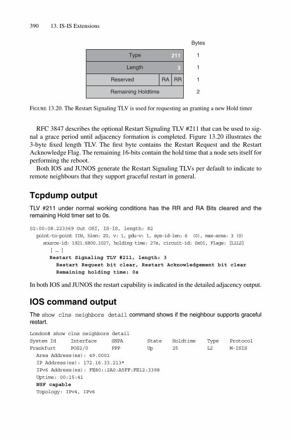
390 13. IS-IS Extensions
RFC 3847 describes the optional Restart Signaling TLV #211 that can be used to sig-nal a grace period until adjacency formation is completed. Figure 13.20 illustrates the 3-byte fixed length TLV. The first byte contains the Restart Request and the RestartAcknowledge Flag. The remaining 16-bits contain the hold time that a node sets itself forperforming the reboot.
Both IOS and JUNOS generate the Restart Signaling TLVs per default to indicate toremote neighbours that they support graceful restart in general.
Tcpdump outputTLV #211 under normal working conditions has the RR and RA Bits cleared and theremaining Hold timer set to 0s.
02:00:08.223369 Out OSI, IS-IS, length: 82
point-to-point IIH, hlen: 20, v: 1, pdu-v: 1, sys-id-len: 6 (0), max-area: 3 (0)
source-id: 1921.6800.1027, holding time: 27s, circuit-id: 0x01, Flags: [L1L2]
[ … ]
Restart Signaling TLV #211, length: 3
Restart Request bit clear, Restart Acknowledgement bit clear
Remaining holding time: 0s
In both IOS and JUNOS the restart capability is indicated in the detailed adjacency output.
IOS command outputThe show clns neighbors detail command shows if the neighbour supports gracefulrestart.
London# show clns neighbors detail
System Id Interface SNPA State Holdtime Type Protocol
Frankfurt POS2/0 PPP Up 25 L2 M-ISIS
Area Address(es): 49.0001
IP Address(es): 172.16.33.213*
IPv6 Address(es): FE80::2A0:A5FF:FE12:3398
Uptime: 00:15:41
NSF capable
Topology: IPv4, IPv6
Type
Length
Reserved
211
Bytes
1
1
1
3
Remaining Holdtime 2
RA RR
FIGURE 13.20. The Restart Signaling TLV is used for requesting an granting a new Hold timer
Graceful Restart 391
In the IOS terminology Non Stop Forwarding (NSF) is an alternative term for gracefulrestart.
JUNOS command outputhannes@Frankfurt> show isis adjacency detail
[ … ]
London
Interface: so-1/2/0.0, Level: 2, State: Up, Expires in 23 secs
Priority: 0, Up/Down transitions: 11, Last transition: 00:24:12 ago
Circuit type: 3, Speaks: IP, IPv6
Topologies: Unicast, IPV6-Unicast
Restart capable: Yes
IP addresses: 172.16.33.29
IPv6 addresses: fe80::203:fdff:fec8:3c00
[ … ]
Graceful restart will be the foundation for higher availability in core networks. It is nota single technology, but rather a concept that allows a node to still forward during con-trol plane failure or intended downtime like router software upgrades. Because gracefulrestart is a cooperative technology (that means it needs to rely on the fact that all of itsneighbours support it) it is recommended to deploy it on a broad scale on every network.
13.7 Summary
The last 10 years were filled with extensions to the IS-IS protocol. Deficits like missingchecksums in certain PDU types got fixed. TLV #10, one of the original ISO 10589TLVs, is used as an envelope to convey HMAC-MD5 strong authentication information.IPv6 routing has been introduced albeit with the same deployment restriction that RFC1195 suffered from. Multi topology IS-IS attempts to solve that problem by definingextra TLVs and introduction per-protocol SPF runs. However, due to broad MPLSdeployment, IPv6 for control plane purposes may become obsolete. BGP in conjunctionwith MPLS as a forwarding magic carpet may finally make MT-ISIS obselete. Finally,IS-IS got the ability for gracefully restarting a control plane processor without churningthe network at all. Extensions like this are the prerequisite for the Internet becoming thedominant public infrastructure some day (soon).

14
Traffic Engineering and MPLS
393
At the end of the 1990s, the Internet was expanding at a breathtaking speed. Both capacityand geographic spread grew by factors of 2 to 4 per year. It appeared that capacity could notbe provisioned in time and the network could suffer congestion anytime. Service providersneeded to re-route traffic onto paths in the network that had been underutilized in order totake some of the load off the congested links. It quickly became evident that the IP worlduntil this time lacked a sound load-balancing tool to adapt the traffic to the underlyingtopology in the most rational manner.
MPLS provided for the first time source routing intelligence to the Internet and, due toits path orientation, the necessary control to guide traffic. However, provisioning the labelswitched paths manually proved to be a daunting task and service providers and routervendors co-developed a kind of distributed traffic control system whereby MPLS pathscan be brought up, loaded with traffic, and torn down based on constraints like bandwidthand hop count limits between POPs. The network service provider is now, for the firsttime, fully in control about the flow of transit traffic, based on high-level constraints likeshop-count, bandwidth utilization, and so on.
In this chapter the original motivations and problems for Internet traffic engineering,the limits of IGP metric balancing the rise of MPLS and the role that IS-IS plays in thedistributed traffic control system will be highlighted. In addition, this chapter coversmore advanced topics like DiffServ traffic engineering and forwarding adjacencies.
14.1 Traffic Engineering by IGP Metric Tweaking
In the IP world, routing protocols try to compute the shortest path between a pair of sub-nets.A common sense example from the real world says that the shortest path may not be the bestpath, as everybody getting stuck in the Monday morning and Friday evening traffic jamson the highways knows. The shortest path from a distance perspective means nothing if theload on that path is too high and therefore causes queuing delays. Consider Figure 14.1,where we have one “hot” link between Frankfurt and London suffering from 110 per centloading and so dropping traffic. Historically network engineers tried to load balance traf-fic by modifying the IGP costs of the links to try and get some of the load off the “hot” link.
IGPs calculate their topology in a highly distributed fashion. If a single link cost ismodified, this may have global impact in the IGP domain. This is not that much of a prob-lem in small networks. On a small network, even a human brain can process the topologyand estimate all the consequences resulting from an IGP link cost change manually.
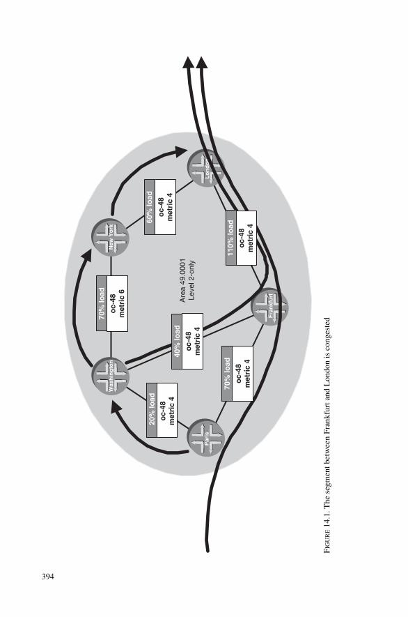
394
Are
a 49
.000
1Le
vel 2
-onl
y
oc-
48m
etri
c 4
70%
load
oc-
48m
etri
c 6
60%
load
oc-
48m
etri
c 4
Fra
nkf
urt
Lo
nd
on
Was
hin
gto
nN
ew Y
ork
Par
is
oc-
48m
etri
c 4
oc-
48m
etri
c 4
70%
load
oc-
48m
etri
c 4
40%
load
20%
load
110%
load
FIG
UR
E14
.1. T
he s
egm
ent b
etw
een
Fran
kfur
t and
Lon
don
is c
onge
sted
Traffic Engineering by Layer-2 Overlay Networks 395
However, in moderately sized networks where the number of routers and links exceeds theprocessing capability of human operators, the IGP acts as a complex system and thereforeproduces undesired side effects during route calculations.
A change in the IGP cost may result in a too drastic change of load patterns across thenetwork. It is almost like people jumping from one side of the bus to the other and almosttipping the bus over. Consider Figure 14.2, where the traffic engineer tries to offload sometraffic on the Frankfurt to London link by changing the link-metric from 4 to 11. Now threelinks (Frankfurt–Paris, Frankfurt–London, Frankfurt–Washington) become unattractive formany routers in the network, and the traffic jumps onto the Washington–London path. Inthe end, nothing is gained, as there is still an imbalance, however, this time on a differentlink in the core network. In this example the change resulted in an even worse overall utili-zation because now two network segments are congested.
The main problem here is the granularity in controlling the traffic. Often the only granu-larity the IGP gives to the traffic engineers is loading or unloading an entire trunk line.Loading and unloading in smaller increments, for example, in 5 per cent incremental stepswould be much better. Network operators need a tool where traffic engineering does not interfere with routing decisions. The first solution for decoupling routing and trafficengineering was achieved using so called Layer-2 overlay network, a popular technique during the mid-1990s.
14.2 Traffic Engineering by Layer-2 Overlay Networks
Figure 14.3 shows the basic structure of a Layer-2 overlay network. The core of the net-work is composed of a set of circuit-oriented Layer-2 switching devices (for example,ATM or Frame Relay switches). Routers sitting at the edge of the network surround theoverlay network core. In the mid-1990s, when this type of network was popular, there wasrelatively little Layer-3 forwarding power. This was the heydays of the Cisco 7500 Series,which could forward at best 200 MBit/s of traffic. Therefore there was a lot of interest tokeep the traffic as long as possible in the Layer-2 switching domain. Consequently, a full-mesh of VCs between the routers was built up. Now, traffic engineering is relatively easy:the traffic engineer simply needs to rearrange the VCs of the core network if a trunk isbecoming congested, or in service provider speak, getting hot.
The bottom of Figure 14.3 shows the router’s viewpoint from a logical perspective.Basically, each router sees each other router. This in turn severely stresses the floodingsub-system of link-state routing protocols enormously. Chapter 6, “Generating, Floodingand Ageing LSPs”, presented more details as to the catastrophic effects such full-meshsetups have during re-routing conditions. Ultimately, the flooding-explosion described inChapter 6 were solved by a technique called mesh-groups.
What remained was not a technical but an administrational problem. In order to managethe router network, service providers needed to run two teams. The ATM team running thecore network was responsible for traffic engineering, and the IP team was responsible forrunning the router infrastructure. Unfortunately, those two responsibilities cannot be strictlyseparated. Traffic engineering in the core is one thing, the other (and more important) aspectis interdomain traffic engineering, which controls the entrance point where traffic enters the

396
Are
a 49
.000
1Le
vel 2
-onl
y
180%
load
oc-
48m
etri
c 6
0% lo
ad
oc-
48m
etri
c 4
0% lo
ad
oc-
48m
etri
c 11
0% lo
ado
c-48
met
ric
4
Fra
nkf
urt
Lo
nd
on
Was
hin
gto
nN
ewY
ork
Par
is
90%
load
oc-
48m
etri
c 4
170%
load
oc-
48m
etri
c 4
FIG
UR
E14
.2. A
cha
nge
of a
sin
gle
IGP
cost
may
hav
e a
glob
al im
pact
on
the
utili
zatio
n of
oth
er tr
unks
in th
e ne
twor
k

IP Network. Consider Figure 14.4, where router New York becomes very attractive byadvertising a lower MED value than router London, and now large traffic volumes arerelayed to router New York. As soon as the traffic arrives at New York, it may become a prob-lem because the only thing left to do is balancing over the existing, internal VC infrastruc-ture. In order to balance traffic efficiently, traffic engineers need to also control the externallink with regard to how much traffic is flowing into the network. This is not an unsolvableproblem; it is a matter of coordination between departments inside a service provider. Butexperience has shown that even this level of minimal coordination is often lacking or just didnot work out very well. Aside from those coordination issues, service providers wanted tohave an integrated solution so that they could perform both traffic engineering and routingon a single platform if for no other reason than cost.
The lack of router knowledge of the underlying topology also causes sometimes weirdre-routing behaviour. Consider Figure 14.5, where the direct VC between Paris andFrankfurt fails. In the IGP topology every VC has a cost of 1. Because there is no directalternate path (cost 1) available, the network takes the next best path which is at a cost of 2.Unfortunately, there are now a whole set of feasible paths available:
• Via Washington DC• Via New York• Via London
Traffic Engineering by Layer-2 Overlay Networks 397
Physical Topology
Logical Topology
Seattle
San Fran
Atlanta
Seattle
San Fran
Atlanta
FIGURE 14.3. In overlay networks all routers are directly connected to each other from a networklayer perspective

Depending on the Paris router configuration, either a random single path or limited setof paths will be picked. In the example, New York has been elected as the backup path,which causes an additional trans-Atlantic delay. The customers were used to havingdelays of about 5 ms between Paris and Frankfurt, and not the resulting 40 ms. And the
398 14. Traffic Engineering and MPLS
AS 65001Area 49.0001Level 2-only
AS 1239
Frankfurt
London
Washington NewYork
Paris
NewYork
London
105% loadoc-48MED 4
20% loadoc-48MED 6
FIGURE 14.4. Interdomain traffic engineering cannot be done using local VC path changes andhence the IP group of a Network Service Provider still has traffic engineering responsibilities
Area 49.0001Level 2-only
1
1
1
1
1
1 11
1
Frankfurt
Washington NewYork
Paris London
1
FIGURE 14.5. Because of lack of topological insight a single failing VC may impose additional delay
trans-Atlantic routes are, by the way, very expensive because this capacity comes at apremium. The other constraint is that routers limit the number of equal cost paths thatthey use for path calculation. IOS used to limit this to six equal cost paths, and JUNOSlimits it to 16 equal cost paths. Now, consider a full-mesh between 40 POPs and only thefirst 6 or 16 equal cost paths are being considered once a single VC fails. This results incompletely unpredictable backup behaviour and is a capacity planner’s nightmare.
In addition to those cost and delay problems, there is also the problem of the Layer-2overhead in ATM networks. An ATM cell consists of a 5-byte header and a 48-byte pay-load. IP packets need to get chopped into pieces to fit in those ATM payload bytes. Asequencing scheme which numbers the fragments and detects the start and end of an IPpacket is needed to reassemble the packet at the end of the cell-switching domain. In theATM world those functions are performed by the ATM Adaptation Layer 5 (AAL-5).Before the IP packet is passed to the segmentation and reassembly (SAR) chip for gen-eration of an ATM AAL-5 compliant cell-stream, a Layer-2 header has to be prependedfor Layer-2 demultiplexing. Recall that at least two protocols are necessary in the net-work: IPv4 and OSI (for conveying the non-IP IS-IS packets). Typically, Layer-2 isimplemented by prepending a Sub Network Access Protocol (SNAP) header for mux-ing/demuxing purposes. A SNAP header ensures that the receiver can differentiatebetween IPv4 and IS-IS packets on the wire. The SNAP, plus the AAL-5 information,represents a certain level of static overhead. However, there is also a dynamic overheadthat results from inefficient packaging of IP packets into cells. Figure 14.6 shows a histogram of the packet size distribution on the Internet as measured by probes on pub-lic peering points. There is a peak of 35.5 per cent at the 40 bytes mark, which accountsfor all the TCP Acknowledgements (ACKs). This is no big surprise as the majority of IPapplications (and hence the majority of traffic) are based on TCP as the transport proto-col. And that is where the problem begins.
Figure 14.7 shows a very good example of the inefficiencies resulting from the dynamicoverhead contribution. Consider a TCP ACK of 40 bytes (20 bytes IP header plus 20 bytesof TCP header) that needs to have a SNAP header prepended, an AAL-5 trailer appended,and finally packaged in ATM cells. A single 40-byte packet with the entire static overheadcontributed by the SNAP header and AAL-5 trailer cannot be squeezed into a single cell,and therefore has to use a second cell. However, in the second cell the majority of infor-mation is padding information. Clearly this is an extreme situation, in the sense that a single 40-byte packet consumes 106 bytes on the carrying media, which is an overhead of 63 per cent! However, there are dynamic overhead peaks resulting from “cell-ification” every48 bytes across the entire packet size distribution histogram. Common experience is thatthe nominal overhead on an Internet traffic mix is about 20 per cent. In other words, only115 MBit/s out of the potential channel capacity of an 148.5 MBit/s SONET/SDH pipecan only be used for transporting IP data. Extrapolating those numbers shows that on anOC-48/STM-16 trunk, roughly 500 MBits of capacity is burned due to cell-ification. Thatrepresents a lot of extra traffic, and also a lot of extra money that service providers couldearn, if they could transport that traffic and not needing to purchase higher-speed trans-mission links, ATM and router equipment.
The third big problem resulting from ATM overlay cores is the reality that router vendors did not make ATM-interfaces with speeds higher than OC-12/STM-4 available.
Traffic Engineering by Layer-2 Overlay Networks 399

Although ATM engineers often claim that this is purely the result of a conspiracy fromthe router vendors (!); the reality is that on the semiconductor supplier market today thereare still no SAR chips available that can segment and reassemble IP packets/cell-streamswith a speed higher than OC-12/STM-4. The main reason for ATM SAR chips trailingbehind the Internet growth curve is due to the technical complexity of generating AAL-5frames at higher wire-speeds.
From an overhead and speed reality point of view, service providers quickly decidedthat the ATM road was a dead-end and provisioned their cores mainly using IP overSONET/SDH technology, thus making the ATM layer essentially obsolete. Somewhatironically, Layer-2 overlay networks were not that bad from a control perspective. Thenicest feature was the level of granularity available to control traffic flow in the core. Theservice provider could easily relay a single portion of City A to City B traffic, without hav-ing any impact on the AS-wide traffic distribution. This can be mainly accounted for bythe path-orientation of ATM VC and Frame Relay DLCIs. It was now clear from thisexperience that any potential integrated traffic engineering solution for IP had to have apath orientation as well.
400 14. Traffic Engineering and MPLS
Internet traffic mixPacket size
(Bytes) Proportion of total Bandwidth (Load)
28 1,20% 0,08%40 35,50% 3,51%44 2,00% 0,22%48 2,00% 0,24%52 3,50% 0,45%
552 0,80% 1,10%576 11,50% 16,40%628 1,00% 1,50%
1420 3,00% 10,50%1500 10,00% 37,10%
Internet packet size/Bandwidth distribution
0,00%
5,00%
10,00%
15,00%
20,00%
25,00%
30,00%
35,00%
40,00%
28 40 44 48 52 552
576
628
1420
1500
Proportion of Total Bandwidth (Total)
FIGURE 14.6. The majority of packets in the Internet are 40-byte sized

401
TC
P A
CK
(40
)A
TM
Hd
r (5
)
AA
L-5
Tra
iler
(8)
LL
CH
ead
er (
3)
AT
M H
dr
(5)
(las
t ce
ll)A
AL
5 p
ad (
40)
53
SN
AP
Hea
der
(5)
5340
40/1
06�
37%
TC
P A
CK
(40
) TC
P A
CK
(40
)48
L3
L2
AA
L5
TC
P A
CK
(40
)A
AL
-5T
raile
r (8
)p
adp
adN
x48
AT
M
LL
CH
ead
er (
3)S
NA
PH
ead
er (
5)
LL
CH
ead
er (
3)S
NA
PH
ead
er (
5)
FIG
UR
E14
.7. T
he w
orst
cas
e sc
enar
io is
a 4
0-by
te p
aylo
ad s
ize,
whi
ch r
equi
res
two
AT
M c
ells

14.3 Traffic Engineering by MPLS
The first big application for MPLS is traffic engineering. Service providers should beable to guide traffic between any two points inside their network. To deviate from theprevailing hop-by-hop routing paradigm that always guides the traffic along the shortestpath through a network, a new forwarding paradigm had to be introduced.
14.3.1 Introduction to MPLSThe forwarding decisions in ATM and Frame Relay networks are truly independent fromthe Network Layer protocol. The forwarding engine itself does not see the NetworkLayer protocol; all it sees is the ATM cell or Frame Relay header. Based on the VPI/VCIor DLCI field, the Layer-2 switch looks up the outgoing port and just as importantly, anoutgoing VPI/VCI or DLCI. Based on this information, the VPI/VCI or DLCI is rewrit-ten before the cell or the packet leaves the router. The VPI/VCI or DLCI field has purelylocal meaning and is only valid on the interface downstream to the receiver. The conceptof label swapping comes from the original ability of ATM and Frame Relay Switches to change the VPI/VCI or DLCI descriptor as the traffic leaves the chassis. It was clear tothe designers of the new MPLS suite of protocols that each IP packet and frame had to bepreceded by an MPLS header in order to support label swapping in the IP protocol family.
The big question today is at what layer the MPLS header needs to exist. There areroughly two, unfortunately, fundamentally different views in the industry:
• MPLS is a Layer-2 technology• MPLS is a Layer-3 technology
In order not to further confuse readers with multiple layering terminologies (ISO layers,ATM layers, IP layers, MPLS layers), this book will typically use the terms cell-basedMPLS for the ATM switch vendors’ view of MPLS as a Layer-2 technology, and packet-based MPLS for the router vendors’ view of MPLS being a Layer-3 technology.
14.3.1.1 Cell-based MPLS
The proponents of MPLS as a Layer-2 technology argue that this transition path for exist-ing ATM networks is the smoothest. The vision is that an existing ATM network whichruns Q.2931 signalling and PNNI for internal routing will be replaced by an IP stack ofsignalling protocols. Figure 14.8 illustrates the control plane transformation of an ATMnetwork to running IS-IS and the combination of one or both of the two major signallingprotocols used with MPLS: LDP and RSVP-TE. As the combination of Q.2931 and PNNIestablished VCIs in the ATM world, now an IP stack sets up the labels in MPLS.
So the main question here is: what is a label in the cell-based MPLS world? In the con-trol plane, much has been changed by radically replacing the prevailing ATM controlplane with an IP one. However, on the forwarding plane, almost nothing has changed.Figure 14.8 shows that cell-based MPLS makes use of the VPI/VCI fields for MPLS aswell. The label will be written into the VPI/VCI fields and the forwarding paradigm staysthe same. The label look up determines the outgoing port and outgoing label, with whichthe cell will be rewritten upon transmission.
402 14. Traffic Engineering and MPLS

403
PN
NI
Q.2
931
Rou
ting
Sig
nalli
ng
Cel
l Hea
der
OS
PF
/IS-I
S
RS
VP
/LD
P
GF
C
VP
I
VC
IP
TC
LP
HE
C
GF
C
Lab
el
PT
CL
PH
EC
FIG
UR
E14
.8. I
n th
e ce
ll-ba
sed
MPL
S w
orld
,IP
prot
ocol
s do
the
labe
l set
up
Although cell-based MPLS may sound as being the panacea for smoothly rolling over toMPLS, there are important caveats to consider. First, cell-Based MPLS cores still need aSAR function at the ingress point of the network for converting IP frames to cells. And thesemiconductor supplier market still lacks SAR chips faster than OC-12/STM-4. So theconclusion is that cell-based MPLS precludes itself for consideration as backbone technol-ogy for high-speed cores. The second important point is that, due to the finite size of thecell-header, there is no possibility for label stacking where multiple path labels are “pushed”and “popped” onto and off packets as they flow in an MPLS network. In large networks itturned out that label stacking is the foundation for scaling the distribution mesh for MPLS-based services. As a brief example, consider Figure 14.9, where for each customer VPN aset of LSPs is set up in the core. To add another customer, another distribution mesh thatconnects all the Provider Edge devices through the core network is needed. Although ATMvendors tune their control planes to process thousands of label setups per second, the sys-tem does not scale in the long run due to its label forwarding state explosion in the core.Consider, for example, 64 customers needing 10 applications which results in more than20,000 connected paths – that amount of customers and paths will stress the control planeseverely and in the long run will exhaust the label space due to the finite cell-header size.
Today, cell-based networks are rarely used for IP transport. Network operators mainlyshare the router vendors’ view that MPLS and its stacking ability are the foundation forscaling services across the network.
14.3.1.2 Packet-based MPLS
In the packet-based MPLS world, MPLS is a fully fledged protocol type that runs on top oflink-layers such as ATM, C-HDLC, Ethernet and PPP. Figure 14.10 shows examples ofhow MPLS is encapsulated on those link-layer protocols. After the Link-Layer Header, a4-byte MPLS “shim header” is added. Interestingly, the MPLS shim header can also bepresent on ATM frames. The nature of MPLS is packet based, however the link-layer isMPLS. Note that packet-based MPLS does not modify the VPI/VCI labels of the ATMheader. The only information that a packet-based MPLS router modifies is the shim header.The MPLS shim header consists of a 20-bit label value plus EXP, S and TTL bits. The labelinformation inside the MPLS shim header is constantly rewritten along the switching pathas in ATM or Frame Relay switch networks. The TTL field carries the same semantics asthe IP TTL field. The main purpose is to prevent harm resulting from persistent forwardingloops. The Experimental or short EXP bits typically carry COS-related information likeForwarding Class Name and drop probability. The last piece of information is only a singlebit, but it gives MPLS its scaling abilities. The Bottom of Stack bit, if set, indicates thatafter the MPLS shim header the Payload (typically the IP packet) is stored. Reverse logicimplies that if the Bottom of Stack bit is not set, then an additional MPLS shim header isfound inside. In other words, MPLS supports label stacking. Those stacking capabilitiesare used for a variety of applications such as VPNs, and also for Traffic Engineering tun-nels for LDP over RSVP-TE tunnelling, which are typically used in large-scale networks.
In order for IP to take advantage of MPLS, IP packets need to get wrapped in MPLSpackets by prepending an MPLS shim header before the IP packet. Adding an MPLS shimto the potential stack of MPLS shims is called a push operation. Consequently, taking off
404 14. Traffic Engineering and MPLS

405
Sha
red
LSP
dis
trib
utio
n m
esh
Pen
nsa
uke
n
Fra
nkf
urt
Was
hin
gto
nN
ew Y
ork
Par
is
Pen
nsau
ken
Lond
onF
rank
furt
Par
is
Lo
nd
on
Per
app
licat
ion
dist
ribut
ion
mes
h
Pen
nsa
uke
n
Fra
nkf
urt
Was
hin
gto
nN
ew Y
ork
Par
is
Pen
nsau
ken
Lond
onF
rank
furt
Par
is
Lo
nd
on
FIG
UR
E14
.9. C
ell-
base
d M
PLS
requ
ires
for
eac
h se
rvic
e a
dedi
cate
d la
bel s
witc
hed
path
mes
h

406
Eth
erne
tD
esti
nat
ion
Mac
So
urc
e M
acE
ther
typ
e0x
8848
4848
16
Pro
toco
l0x
8848
16
HD
LC
0x00
FF
HD
LC
0xF
F03
Pro
toco
l0x
0281
16 1616
Lab
elE
XP
ST
TL
203
18
Lab
elE
XP
ST
TL
203
18
Lab
elE
XP
ST
TL
203
18
Cis
co H
DLC
PP
P
16
Lab
elE
XP
ST
TL
203
18
sub
Pro
to-I
D0x
8848
OU
I0x
0P
roto
-ID
0xA
AA
A03
2424
AT
M S
NA
P
MP
LS
sh
im h
ead
er
FIG
UR
E14
.10.
The
MPL
S sh
im h
eade
r is
trea
ted
like
an O
SI-R
M L
ayer
-3 p
roto
col a
nd c
an b
e ru
n o v
er a
var
iety
of
link-
laye
r pr
otoc
ols
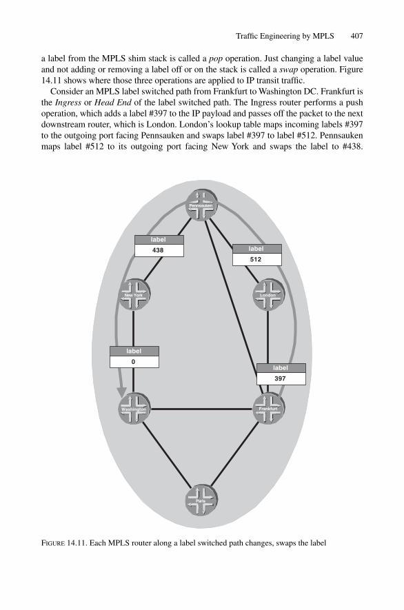
a label from the MPLS shim stack is called a pop operation. Just changing a label valueand not adding or removing a label off or on the stack is called a swap operation. Figure14.11 shows where those three operations are applied to IP transit traffic.
Consider an MPLS label switched path from Frankfurt to Washington DC. Frankfurt isthe Ingress or Head End of the label switched path. The Ingress router performs a pushoperation, which adds a label #397 to the IP payload and passes off the packet to the nextdownstream router, which is London. London’s lookup table maps incoming labels #397to the outgoing port facing Pennsauken and swaps label #397 to label #512. Pennsaukenmaps label #512 to its outgoing port facing New York and swaps the label to #438.
Traffic Engineering by MPLS 407
Pennsauken
Frankfurt
London
Washington
New York
Paris
label
397
label
512
label
438
label
0
FIGURE 14.11. Each MPLS router along a label switched path changes, swaps the label

Pennsauken is the penultimate router on the forwarding path and therefore it has to tell theegress router to unwrap the packet. It does so by swapping the label to zero and forward-ing it to Washington. The Egress or tail end router in Washington knows now to POP thetop label off the stack and do a regular IP lookup on the packet inside.
14.4 MPLS Signalling Protocols
Now the next big question is: how are label switched paths established? As in the routingprotocol world, there are generally two ways to bring up label switched paths:
• Static setup• Dynamic (signalled) setup
Static setups have no real practical relevance: they are difficult to coordinate and to setup and cumbersome to maintain. Additionally they do not have the possibility to re-routetraffic in case the primary path fails. The majority of network operators deployed sig-nalled setup of label switched paths using one or both of the following protocols: LDPand RSVP-TE.
Path control is one of the prime necessities of traffic engineering. LDP is not directlyrelated to traffic engineering because LDP lacks support for traffic path control. Althoughthere is an extension to LDP that allows traffic path control based on constraints calledCR-LDP the new extensions never materialized in real networks. Finally the CR-LDP gotabandoned by the IETF. Today’s protocol of choice for traffic-path control is RSVP, aug-mented with a Traffic Engineering Extension, called RSVP-TE. This chapter covers onlyLDP basics, and just to provide a better understanding about how LDP fits in with moreadvanced concepts like LDP over RSVP-TE tunnelling, which is related to traffic engin-eering and IS-IS.
14.4.1 RSVP-TERSVP was originally defined in RFC 2205, however, with completely different intentionsthan using it for traffic engineering purposes. Originally it was thought of as being the toolto make the Internet CoS aware. The application running on End Systems should be madeCoS aware and signal bandwidth and delay requirements to the network, which wasexpected to provide for these requirements. The RSVP message travels throughout thenetwork and, if the receiver confirms that it is willing to accept traffic according to theflow request, then admission is granted. Then all routers across the path are required to setup per-flow schedulers to guarantee that the individual application can transmit the trafficwith the requirements granted by the network. The per-flow model failed due to the inher-ent scaling problems of implementing it in hardware. This was to some degree compar-able to ATM networks, where a similar mistake was made – dynamic signalling of ATM VCsand the subsequent introduction of forwarding state does not scale. Consider that today onan OC-192c circuit there are typically millions of flows transported, then the limits of thedesign are immediately apparent. A hardware-scheduling engine that operates at such highspeeds on so many flows cannot be built. RSVP was considered dead by the mid-1990s
408 14. Traffic Engineering and MPLS
MPLS Signalling Protocols 409
and there was no broader deployment of flow-aware networks. Finally, the vision of aflow-aware Internet was abandoned for the time being. However, there were three thingsabout RSVP that still attracted interest within the developer community.
1. Extensibility. First of all, RSVP is a very extensible protocol. Like IS-IS, the RSVPheader is quite generic and all the information is encoded using TLV containers calledObjects. More about the advantages of TLV encoding were discussed in Chapter 13.Virtually all successful networking protocols have a TLV orientation. RSVP is actu-ally a very good example of a protocol that, if it is just extensible enough, can be usedfor a totally different purpose many years later. All that is required is to define a dif-ferent set of TLVs, and functionality is added as developers move forward with theprotocol.
2. Forwarding State Model. RSVP uses two basic messages for requesting and grantingforwarding state: the PATH and the RESV messages. The Path message describes what the sender wants to transmit to the receiver, and the RESV message describeswhat the receiver is willing to accept. The PATH message travels hop-by-hop down-stream to the receiver and the RESV message travels upstream from the receiver to thesender along the path established. The receiver can set up forwarding state in a step-by-step fashion and, as soon the RESV message arrives at the requester, everything isready and then the forwarding path can immediately be used. That property is a widedeviation from the usual “signalling” and routing paradigm found in IP networks.Routing typically does not get any feedback – at best a routing protocol tells its neigh-bour that it has received the routing update by sending back an Acknowledgement.However, the router cannot tell if the path will ever be used. RSVP is different. Therouter that requests a certain forwarding state from the network also gets immediatefeedback that the network has set up the requesting state and now it is ready for use.For fast converging networks especially, fast feedback about whether a path can beused or not is imperative.
3. Unidirectional Notion. A flow was originally thought of as a unidirectional path betweentwo nodes. Also, routed paths in the IP world are always unidirectional relationships.Therefore the IETF similarly defined a label switched path as a unidirectional rela-tionship. As the RSVP flow-based model implied unidirectional operation as well, itwas a natural choice for setting up label forwarding state between a pair of routers.
14.4.2 Simple Traffic Engineering with RSVP-TERSVP had a lot of interesting ingredients to serve as the protocol for setting up labelswitched paths across the Internet. However, a few changes and extra objects had to bedefined before RSVP could be used to set up label switched paths. The most importantchange was that RSVP is not run between a pair of End Systems. Rather, RSVP-TE forMPLS is run between a pair of routers. The next evolutionary step was to get rid of someof the per-flow objects and to define a set of new objects that could be used for trafficengineering purposes. In RSVP, Objects is the term that is interchangeably used for TLVs.
Table 14.1 shows the additional RSVP-TE objects that are defined in RFC 3209 andused with MPLS.
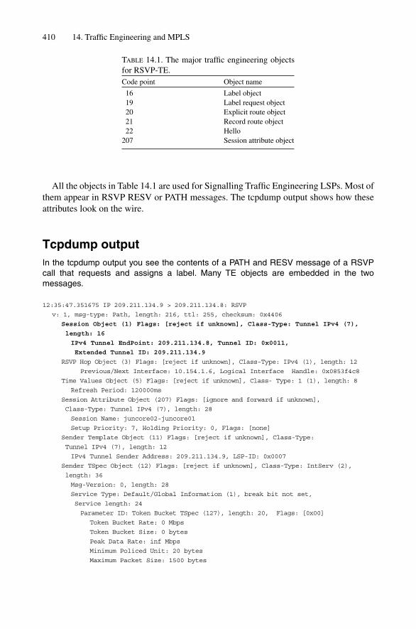
All the objects in Table 14.1 are used for Signalling Traffic Engineering LSPs. Most ofthem appear in RSVP RESV or PATH messages. The tcpdump output shows how theseattributes look on the wire.
Tcpdump outputIn the tcpdump output you see the contents of a PATH and RESV message of a RSVP call that requests and assigns a label. Many TE objects are embedded in the two messages.
12:35:47.351675 IP 209.211.134.9 > 209.211.134.8: RSVP
v: 1, msg-type: Path, length: 216, ttl: 255, checksum: 0x4406
Session Object (1) Flags: [reject if unknown], Class-Type: Tunnel IPv4 (7),
length: 16
IPv4 Tunnel EndPoint: 209.211.134.8, Tunnel ID: 0x0011,
Extended Tunnel ID: 209.211.134.9
RSVP Hop Object (3) Flags: [reject if unknown], Class-Type: IPv4 (1), length: 12
Previous/Next Interface: 10.154.1.6, Logical Interface Handle: 0x0853f4c8
Time Values Object (5) Flags: [reject if unknown], Class- Type: 1 (1), length: 8
Refresh Period: 120000ms
Session Attribute Object (207) Flags: [ignore and forward if unknown],
Class-Type: Tunnel IPv4 (7), length: 28
Session Name: juncore02-juncore01
Setup Priority: 7, Holding Priority: 0, Flags: [none]
Sender Template Object (11) Flags: [reject if unknown], Class-Type:
Tunnel IPv4 (7), length: 12
IPv4 Tunnel Sender Address: 209.211.134.9, LSP-ID: 0x0007
Sender TSpec Object (12) Flags: [reject if unknown], Class-Type: IntServ (2),
length: 36
Msg-Version: 0, length: 28
Service Type: Default/Global Information (1), break bit not set,
Service length: 24
Parameter ID: Token Bucket TSpec (127), length: 20, Flags: [0x00]
Token Bucket Rate: 0 Mbps
Token Bucket Size: 0 bytes
Peak Data Rate: inf Mbps
Minimum Policed Unit: 20 bytes
Maximum Packet Size: 1500 bytes
410 14. Traffic Engineering and MPLS
TABLE 14.1. The major traffic engineering objectsfor RSVP-TE.Code point Object name
16 Label object19 Label request object20 Explicit route object21 Record route object22 Hello
207 Session attribute object

Adspec Object (13) Flags: [reject if unknown], Class-Type: IntServ (2),
length: 48
Msg-Version: 0, length: 40
Service Type: Default/Global Information (1), break bit not set,
Service length: 32
Parameter ID: IS hop cnt (4), length: 4, Flags: [0x00]
IS hop cnt: 1
Parameter ID: Path b/w estimate (6), length: 4, Flags: [0x00]
Path b/w estimate: 0 Mbps
Parameter ID: Minimum path latency (8), length: 4, Flags: [0x00]
Minimum path latency: don’t care
Parameter ID: Composed MTU (10), length: 4, Flags: [0x00]
Composed MTU: 1500 bytes
Service Type: Controlled Load (5), break bit not set, Service length: 0
ERO Object (20) Flags: [reject if unknown], Class-Type: IPv4 (1), length: 28
Subobject Type: IPv4 prefix, Strict, 10.154.1.5/32, Flags: [none]
Subobject Type: IPv4 prefix, Strict, 10.154.6.1/32, Flags: [none]
Subobject Type: IPv4 prefix, Strict, 10.254.1.45/32, Flags: [none]
Label Request Object (19) Flags: [reject if unknown], Class- Type: without
label range (1), length: 8
L3 Protocol ID IPv4
RRO Object (21) Flags: [reject if unknown], Class-Type: IPv4 (1), length: 12
Subobject Type: IPv4 prefix, Strict, 10.154.1.6/32, Flags: [none]
This is the response to the previous Label Setup Message. Note that the Session objectcontents need to match in order for the router to match the RSVP message to a certainsession.
12:35:51.199611 IP (tos 0xc0, ttl 255, id 6344, offset 0, flags [none], length: 164)
10.154.1.5 > 10.154.1.6: RSVP
v: 1, msg-type: Resv, length: 144, ttl: 255, checksum: 0x2efc
Session Object (1) Flags: [reject if unknown], Class-Type: Tunnel IPv4 (7),
length: 16
IPv4 Tunnel EndPoint: 209.211.134.10, Tunnel ID: 0x0013, Extended
Tunnel ID: 209.211.134.9
RSVP Hop Object (3) Flags: [reject if unknown], Class-Type: IPv4 (1), length: 12
Previous/Next Interface: 10.154.1.5, Logical Interface Handle: 0x0853f4c8
Time Values Object (5) Flags: [reject if unknown], Class-Type: 1 (1), length: 8
Refresh Period: 30000ms
Style Object (8) Flags: [reject if unknown], Class-Type: 1 (1), length: 8
Reservation Style: Fixed Filter, Flags: [0x00]
Flowspec Object (9) Flags: [reject if unknown], Class-Type: IntServ (2),
length: 36
Msg-Version: 0, length: 28
Service Type: Controlled Load (5), break bit not set, Service length: 24
Parameter ID: Token Bucket TSpec (127), length: 20, Flags: [0x00]
Token Bucket Rate: 0 Mbps
Token Bucket Size: 0 bytes
Peak Data Rate: inf Mbps
Minimum Policed Unit: 20 bytes
Maximum Packet Size: 1500 bytes
MPLS Signalling Protocols 411
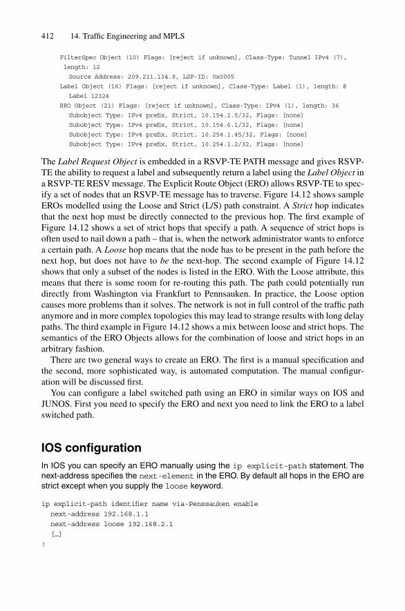
FilterSpec Object (10) Flags: [reject if unknown], Class-Type: Tunnel IPv4 (7),
length: 12
Source Address: 209.211.134.9, LSP-ID: 0x0005
Label Object (16) Flags: [reject if unknown], Class-Type: Label (1), length: 8
Label 12324
RRO Object (21) Flags: [reject if unknown], Class-Type: IPv4 (1), length: 36
Subobject Type: IPv4 prefix, Strict, 10.154.1.5/32, Flags: [none]
Subobject Type: IPv4 prefix, Strict, 10.154.6.1/32, Flags: [none]
Subobject Type: IPv4 prefix, Strict, 10.254.1.45/32, Flags: [none]
Subobject Type: IPv4 prefix, Strict, 10.254.1.2/32, Flags: [none]
The Label Request Object is embedded in a RSVP-TE PATH message and gives RSVP-TE the ability to request a label and subsequently return a label using the Label Object ina RSVP-TE RESV message. The Explicit Route Object (ERO) allows RSVP-TE to spec-ify a set of nodes that an RSVP-TE message has to traverse. Figure 14.12 shows sampleEROs modelled using the Loose and Strict (L/S) path constraint. A Strict hop indicatesthat the next hop must be directly connected to the previous hop. The first example ofFigure 14.12 shows a set of strict hops that specify a path. A sequence of strict hops isoften used to nail down a path – that is, when the network administrator wants to enforcea certain path. A Loose hop means that the node has to be present in the path before thenext hop, but does not have to be the next-hop. The second example of Figure 14.12shows that only a subset of the nodes is listed in the ERO. With the Loose attribute, thismeans that there is some room for re-routing this path. The path could potentially rundirectly from Washington via Frankfurt to Pennsauken. In practice, the Loose optioncauses more problems than it solves. The network is not in full control of the traffic pathanymore and in more complex topologies this may lead to strange results with long delaypaths. The third example in Figure 14.12 shows a mix between loose and strict hops. Thesemantics of the ERO Objects allows for the combination of loose and strict hops in anarbitrary fashion.
There are two general ways to create an ERO. The first is a manual specification andthe second, more sophisticated way, is automated computation. The manual configur-ation will be discussed first.
You can configure a label switched path using an ERO in similar ways on IOS andJUNOS. First you need to specify the ERO and next you need to link the ERO to a labelswitched path.
IOS configurationIn IOS you can specify an ERO manually using the ip explicit-path statement. Thenext-address specifies the next-element in the ERO. By default all hops in the ERO arestrict except when you supply the loose keyword.
ip explicit-path identifier name via-Penssauken enable
next-address 192.168.1.1
next-address loose 192.168.2.1
[…]
!
412 14. Traffic Engineering and MPLS

MPLS Signalling Protocols 413
Area 49.0001Level 2-only
ERO
Paris strict;Frankfurt strict;London strict;Pennsauken strict;
Area 49.0001Level 2-only
ERO
Frankfurt loose;Pennsauken loose;
Area 49.0001Level 2-only
ERO
Frankfurt strict;Pennsauken loose;
Pennsauken
Frankfurt London
Washington New York
Paris
Pennsauken
Frankfurt London
Washington New York
Paris
Pennsauken
Frankfurt London
Washington New York
Paris
FIGURE 14.12. The ERO consists of a mix and match list of Strict and/or Loose Hops

After defining the ERO you need to link it to an existing tunnel using the path-option explicit argument to the tunnel mpls traffic-eng command.
IOS configurationIn order to switch from dynamic computation to an explicit execution use the tunnel mplstraffic-eng path-option 5 explicit command.
interface Tunnel0
description TE Tunnel to Washington via Penssauken
ip unnumbered Loopback0
tag-switching ip
tunnel destination 192.168.20.1
tunnel mode mpls traffic-eng
tunnel mpls traffic-eng autoroute announce
tunnel mpls traffic-eng path-option 5 explicit name via-Penssauken
!
In JUNOS the configuration is very similar – first you specify the ERO.
JUNOS configurationIn JUNOS you configure manual EROs under the protocols mpls path {} configura-tion branch.
protocols {
mpls {
path via-Penssauken {
192.168.1.1 strict;
192.168.2.1 loose;
}
}
}
Next you link the ERO into an existing label switched path. You need to declare thepath as a primary or secondary path.
JUNOS configurationThe tunnel is configured under the protocols mpls label-switched-path {} state-ment. JUNOS has the notion of a primary/secondary path where you can specify abackup path that is immediately used if the primary path fails.
protocols {
mpls {
label-switched-path “TE Tunnel to Washington via Pennsauken” {
to 192.168.20.1;
primary via-Pennsauken;
}
}
}
414 14. Traffic Engineering and MPLS
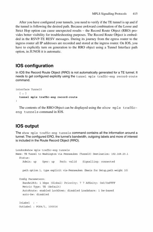
After you have configured your tunnels, you need to verify if the TE tunnel is up and ifthe tunnel is following the desired path. Because awkward combination of the Loose andStrict Hop option can cause unexpected results – the Record Route Object (RRO) pro-vides better visibility for troubleshooting purposes. The Record Route Object is embed-ded in the RSVP-TE RESV messages. During its journey from the egress router to theingress router all IP addresses are recorded and stored at the ingress router. On IOS, youhave to explicitly turn on generation to the RRO object using a Tunnel Interface pathoption, in JUNOS it is automatic.
IOS configurationIn IOS the Record Route Object (RRO) is not automatically generated for a TE tunnel. Itneeds to get configured explicitly using the tunnel mpls traffic-eng record-routecommand.
interface Tunnel0
[ … ]
tunnel mpls traffic-eng record-route
!
The contents of the RRO Object can be displayed using the show mpls traffic-eng tunnels command in IOS.
IOS outputThe show mpls traffic-eng tunnels command contains all the information around atunnel. The configured ERO, the tunnel’s bandwidth, outgoing labels and more of interestis included in the Route Record Object (RRO).
London#show mpls traffic-eng tunnels
Name: TE Tunnel to Washington via Pennsauken (Tunnel0) Destination: 192.168.20.1
Status:
Admin: up Oper: up Path: valid Signalling: connected
path option 1, type explicit via-Pennsauken (Basis for Setup,path weight 10)
Config Parameters:
Bandwidth: 1 kbps (Global) Priority: 7 7 Affinity: 0x0/0xFFFF
Metric Type: TE (default)
AutoRoute: enabled LockDown: disabled Loadshare: 1 bw-based
auto-bw: disabled
InLabel : -
OutLabel : POS4/1, 100016
MPLS Signalling Protocols 415

RSVP Signalling Info:
Src 192.168.1.2, Dst 192.168.20.1, Tun_Id 0, Tun_Instance 511
RSVP Path Info:
My Address: 192.168.1.2
Explicit Route: 192.168.1.1 192.168.168.3
Record Route:
Tspec: ave rate�1 kbits, burst�1000 bytes, peak rate�1 kbits
RSVP Resv Info:
Record Route: 172.16.33.1 172.16.38.1
Fspec: ave rate�1 kbits, burst�1000 bytes, peak rate�1 kbits
History:
Tunnel:
Time since created: 12 days, 17 hours, 39 minutes
Time since path change: 1 minutes, 13 seconds
Current LSP:
Uptime: 1 minutes, 13 seconds
Most often you will notice a difference between the configured ERO and the recordedPATH. It is common practice to use a router’s loopback ID as the address for a loose hop. However, the route recorder in the PATH message thinks entirely in terms of linkaddresses. So even if we used in our example the 192.168/16 addresses, the ones actuallyreported back in the RRO are from the link-address space 172.16/16.
In JUNOS you can also display the recorded path using the show mpls lspingress detail command.
JUNOS outputhannes@Frankfurt> show mpls lsp ingress detail
Ingress LSP: 1 sessions
192.168.1.1
From: 192.168.1.2, State: Up, ActiveRoute: 0, LSPname: to-Washington
ActivePath: (primary)
LoadBalance: Random
Encoding type: Packet, Switching type: Packet, GPID: IPv4
*Primary State: Up
Computed ERO (S [L] denotes strict [loose] hops): (CSPF metric: 20)
192.168.1.1 192.168.168.3 S
Received RRO (ProtectionFlag 1�Available 2�InUse 4�B/W 8�Node):
172.16.33.1 172.16.38.1
Total 1 displayed, Up 1, Down 0
JUNOS behaves similarly to IOS, where the Route Path Recording is done using linkaddresses.
If you want to achieve any-to-any MPLS connectivity between all routers in your network, then the consequence is to deploy a full-mesh of RSVP-TE tunnels. However,there are severe scaling implications with that approach. To overcome these scaling limitations a more lightweight MPLS label setup protocol called the Label DistributionProtocol (LDP) is used.
416 14. Traffic Engineering and MPLS

14.4.3 LDPLDP is defined in RFC 3036 and it describes a lean, lightweight protocol that brings up afull-mesh of connectivity to all LDP speakers in the network. Generally, the term full-mesh raises warning flags in every network engineer’s head due to the perceived scalingproblems. However, LDP uses a technique called label-merging which is very conserva-tive with label allocation. Consider the right-hand side of Figure 14.13. There are fivedrawings inside the figure, one for each possible egress router. The egress router is markedwith an E, and the metric on each link is 4.
MPLS Signalling Protocols 417
Frankfurt
Pa
LDP label allocation
6
4
4
4
4
4
6
4
4
4
4
4
6
4
4
4
4
4
6
4
4
4
4
4
6
4
4
4
4
4
RSVP label allocation
6
4
4
4
4
4
6
4
4
4
4
4
6
4
4
4
4
4
6
4
4
4
4
4
6
4
4
4
4
4
Frankfurt
London
Washington NewYork
Paris
E
E
Frankfurt
London
Washington New York
Paris
Frankfurt
London
Washington NewYork
Paris
Frankfurt
London
Washington NewYork
Paris
Frankfurt
London
Washington New York
Paris
Frankfurt
London
Washington New York
Paris
Frankfurt
London
Washington NewYork
Paris
Frankfurt
London
Washington NewYork
Paris
Frankfurt
London
Washington New York
Paris
Frankfurt
London
Washington NewYork
Paris
E
E
E E
E
E
E
E
FIGURE 14.13. LDP consumes less forwarding state per link than RSVP does

The figure describes the LSPs and the necessary forwarding state to set up full-meshconnectivity between all five routers in the core network. Using RSVP-TE, we wouldneed at least N * (N – 1)/2 � 10 explicitly configured tunnels. Because LDP supports labelmerging, some labels can be re-used by other label switched paths. Unlike RSVP-TE,LDP signals its label using a mode called downstream unsolicited, which means that the labels are signalled from the egress router to the ingress router. Each LDP speakeradvertises prefixes according to the egress policy. In JUNOS, the default egress policy isjust to advertise the loopback IP address. The IOS default egress policy is to advertise boththe loopback and all the directly connected interfaces. Upstream nodes create MPLSSWAP states and pass on the label-mapping message to their upstream nodes, which cre-ate again MPLS SWAP states, and pass them on to further upstream nodes, and so on. Theresulting shape of the merged tree is called a sink tree. (In datacom speech the egress ordestination point is sometimes called the sink.) And because the root of the tree is at theegress router, it is therefore a sink tree.
Figure 14.14 shows the number of forwarding entries (FE) that the sum of all labelswitched paths generates. Even in the small topology, LDP behaves better than RSVP-TE. LDP has an average of 3 FEs per link versus RSVP-TE, which consumes anaverage of 4.33 FEs per link. LDP is therefore the protocol of choice for edge systemslike VPN and/or customer access routers, due to LDP’s ability to supply a full-mesh con-nectivity to all the other LDP speakers with no setup complexity at all.
The configuration of LDP is a simple one: just enable it on a per-interface basis. AnLDP configuration for router London on IOS could look like the following:
IOS configurationIn IOS two configuration lines are necessary for running LDP. First turn on MPLS pro-cessing on an interface plus the necessary Layer-2 Supporting Protocols like MPLSCPover PPP using the tag-switching ip keyword. The mpls label protocol ldp key-word tells the system to run LDP rather than TDP (Cisco’s proprietary predecessor to LDP).
London#sh running-config
[ … ]
!
interface POS4/1
ip address 172.17.0.5 255.255.255.252
ip router isis
encapsulation ppp
mpls label protocol ldp
tag-switching ip
!
Shortly after configuration, a remote LDP neighbour should be detected and an LDPsession is then set up automatically. You can verify the neighbour state using the showmpls ldp neighbor operational level command.
418 14. Traffic Engineering and MPLS

419
Fo
rwar
din
g s
tate
/LD
P la
bel
allo
cati
on
Fo
rwar
din
g s
tate
/RS
VP
lab
el a
lloca
tio
n
8 F
E
4 F
E
4 F
E
4 F
E
3 F
E
3 F
E
4 F
E
2 F
E
3 F
E
3 F
E
3 F
E
3 F
E
avg
. 3 F
E/L
INK
avg
. 4.
33 F
E/L
INK
Fra
nkf
urt
Lo
nd
on
Was
hin
gto
nN
ew Y
ork
Par
is
Fra
nkf
urt
Lo
nd
on
Was
hin
gto
nN
ew Y
ork
Par
is
FIG
UR
E14
.14.
The
sum
of
all f
orw
ardi
ng s
tate
s sh
ow th
at L
DP
is m
ore
frug
al th
an R
SVP

IOS outputUnder the show mpls ldp <*> hierarchy several commands are available to verify neigh-bour state and timers.
London#show mpls ldp neighbor
Peer LDP Ident: 192.168.0.1:0; Local LDP Ident 192.168.13.8:0
TCP connection: 192.168.0.1.646 - 192.168.13.8.11000
State: Oper; Msgs sent/rcvd: 207/179; Downstream
Up time: 00:28:43
LDP discovery sources:
POS4/0, Src IP addr: 172.16.0.2
Addresses bound to peer LDP Ident:
172.16.0.2
The display output shows whether the session is up and what IP addresses are beingused. LDP uses link IP addresses for discovery and loopback IP addresses for sessionsetup. If a session does not come up due to addressing conflicts the output of this com-mand is providing valuable information for troubleshooting.
In JUNOS we need to make sure that family mpls is configured under the logicalinterface branch. In addition we add a list of interfaces where we want to speak LDPunder the protocols ldp stanza.
JUNOS configurationIn JUNOS you need to specify the interface where you want to run LDP both under theprotocols mpls {} and protocols ldp {} stanza. Alternatively you can set the mplsinterface list to all which allows allocation of labels on all interfaces. In addition everylogical interface needs to have the family mpls configured.
hannes@Frankfurt# show
[ … ]
interface ge-0/0/0 {
unit 0 {
family mpls;
}
}
protocols {
mpls {
interface all;
}
ldp {
interface so-0/1/2.0;
}
}
[ … ]
It remains unknown why mpls interface all {} is not the default option,since this does not break anything by being turned on. On the other hand, it does break
420 14. Traffic Engineering and MPLS
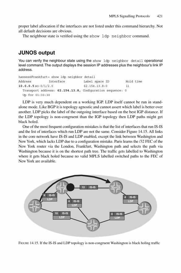
proper label allocation if the interfaces are not listed under this command hierarchy. Notall default decisions are obvious.
The neighbour state is verified using the show ldp neighbor command.
JUNOS outputYou can verify the neighbour state using the show ldp neighbor detail operationallevel command.The output displays the session IP addresses plus the neighbour’s link IPaddress.
hannes@Frankfurt> show ldp neighbor detail
Address Interface Label space ID Hold time
10.0.0.5 so-0/1/2.0 62.154.13.8:0 11
Transport address: 62.154.13.8, Configuration sequence: 0
Up for 01:33:30
LDP is very much dependent on a working IGP. LDP itself cannot be run in stand-alone mode. Like BGP it is topology agnostic and cannot assert which label is better overanother. LDP picks the label of the outgoing interface based on the best IGP distance. Ifthe LDP topology is non-congruent than the IGP topology then LDP paths might getblack holed.
One of the most frequent configuration mistakes is that the list of interfaces that run IS-ISand the list of interfaces which run LDP are not the same. Consider Figure 14.15. All linksin the core network have IS-IS and LDP enabled, except the link between Washington andNew York, which lacks LDP due to a configuration mistake. Paris learns the /32 FEC of theNew York router via the London, Frankfurt, Washington path and selects the path viaWashington because it is on the shortest path tree. The traffic gets labelled to Washingtonwhere it gets black holed because no valid MPLS labelled switched paths to the FEC of New York are available.
MPLS Signalling Protocols 421
10 IS-IS
LDP
4 IS-IS
LDP
12 IS-IS
4 IS-ISLDP
4 IS-IS
LDP
Frankfurt
London
Washington NewYork
Paris
4 IS-IS
LDP
FIGURE 14.15. If the IS-IS and LDP topology is non-congruent Washington is black holing traffic
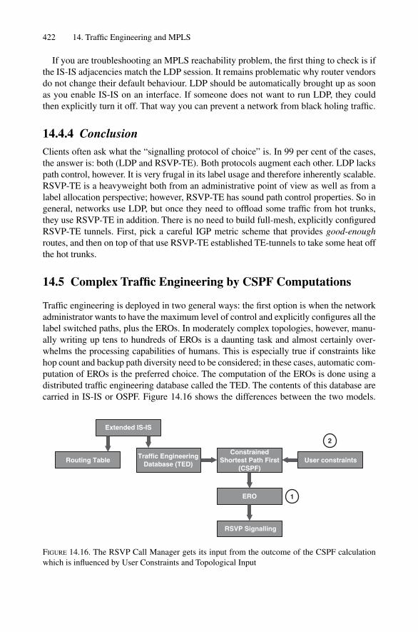
If you are troubleshooting an MPLS reachability problem, the first thing to check is ifthe IS-IS adjacencies match the LDP session. It remains problematic why router vendorsdo not change their default behaviour. LDP should be automatically brought up as soonas you enable IS-IS on an interface. If someone does not want to run LDP, they couldthen explicitly turn it off. That way you can prevent a network from black holing traffic.
14.4.4 ConclusionClients often ask what the “signalling protocol of choice” is. In 99 per cent of the cases,the answer is: both (LDP and RSVP-TE). Both protocols augment each other. LDP lackspath control, however. It is very frugal in its label usage and therefore inherently scalable.RSVP-TE is a heavyweight both from an administrative point of view as well as from alabel allocation perspective; however, RSVP-TE has sound path control properties. So ingeneral, networks use LDP, but once they need to offload some traffic from hot trunks,they use RSVP-TE in addition. There is no need to build full-mesh, explicitly configuredRSVP-TE tunnels. First, pick a careful IGP metric scheme that provides good-enoughroutes, and then on top of that use RSVP-TE established TE-tunnels to take some heat offthe hot trunks.
14.5 Complex Traffic Engineering by CSPF Computations
Traffic engineering is deployed in two general ways: the first option is when the networkadministrator wants to have the maximum level of control and explicitly configures all thelabel switched paths, plus the EROs. In moderately complex topologies, however, manu-ally writing up tens to hundreds of EROs is a daunting task and almost certainly over-whelms the processing capabilities of humans. This is especially true if constraints likehop count and backup path diversity need to be considered; in these cases, automatic com-putation of EROs is the preferred choice. The computation of the EROs is done using adistributed traffic engineering database called the TED. The contents of this database arecarried in IS-IS or OSPF. Figure 14.16 shows the differences between the two models.
422 14. Traffic Engineering and MPLS
Extended IS-IS
Routing TableTraffic Engineering
Database (TED)
ConstrainedShortest Path First
(CSPF)User constraints
ERO
RSVP Signalling
2
1
FIGURE 14.16. The RSVP Call Manager gets its input from the outcome of the CSPF calculationwhich is influenced by User Constraints and Topological Input

In the first method, the network administrator supplies the ERO data, and in the second theEROs are calculated using a Constrained Shortest Path First Calculation (CSPF) based onuser constrained TED input from the routers. The final result is an ERO which gets passedto RSVP-TE for LSP setup.
You can display the contents of the TED database using the show mpls traffic-eng topology command in IOS and show ted database extensive com-mand in JUNOS.
IOS command outputLondon#show mpls traffic-eng topologyMy_System_id: 1921.6800.1008.00 (isis level-2)
Signalling error holddown: 10 sec Global Link Generation 5
IGP Id: 1921.6800.1012.00, MPLS TE Id:192.168.0.12 Router Node (isis level-2)link[0]: Point-to-Point, Nbr IGP Id: 1921.6800.1008.00, nbr_node_id:1, gen:2
frag_id 0, Intf Address:172.16.0.2, Nbr Intf Address:172.16.0.1TE metric:10, IGP metric:10, attribute_flags:0x0physical_bw: 2488320 (kbps), max_reservable_bw_global: 2488320 (kbps)max_reservable_bw_sub: 0 (kbps)
Global Pool Sub PoolTotal Allocated Reservable ReservableBW (kbps) BW (kbps) BW (kbps)--------------- ----------- ----------
bw[0]: 0 2488320 0bw[1]: 0 2488320 0bw[2]: 0 2488320 0bw[3]: 0 2488320 0bw[4]: 0 2488320 0bw[5]: 0 2488320 0bw[6]: 0 2488320 0bw[7]: 0 2488320 0
The TED database contains all IP addresses, links and current bandwidth reservationstates. The data found here is the foundation for the CSPF calculation which produces apath described by an ERO.
JUNOS command outputhannes@Frankfurt> show ted database extensive
TED database: 3 ISIS nodes 3 INET nodes
NodeID: Frankfurt.00(192.168.0.8)
Type: Rtr, Age: 189 secs, LinkIn: 1, LinkOut: 1
Protocol: IS-IS(2)
To: London.00(192.168.0.8), Local: 172.16.0.1, Remote: 172.16.0.2
Color: 0 <none>
Metric: 10
Static BW: 2488.32Mbps
Reservable BW: 2488.32Mbps
Complex Traffic Engineering by CSPF Computations 423

Available BW [priority] bps:
[0] 2488.32Mbps [1] 2488.32Mbps [2] 2488.32Mbps [3] 2488.32Mbps
[4] 2488.32Mbps [5] 2488.32Mbps [6] 2488.32Mbps [7] 2488.32Mbps
Interface Switching Capability Descriptor(1):
Switching type: Packet
Encoding type: Packet
Maximum LSP BW [priority] bps:
[0] 2488.32Mbps [1] 2488.32Mbps [2] 2488.32Mbps [3] 2488.32Mbps
[4] 2488.32Mbps [5] 2488.32Mbps [6] 2488.32Mbps [7] 2488.32Mbps
Why isn’t the data for CSPF calculations taken straight from the link-state database ofthe routing protocol? Well, there still may be OSPF deployed in parts of the network. TheTED is a unified view to the topology of the network, so no matter which IGP (OSPF,IS-IS, or even vendor-proprietary protocols) supplied the topology data. The TED is aunified, abstracted view and knows only about nodes, links and link attributes.
How does IS-IS generate and encode the data in the TED output? How does it knowthat a certain interface is an OC-48 interface? As soon as RSVP-TE is enabled on aninterface, a lot of extra information is generated and conveyed using IS-IS.
Consider the following tcpdump output of a LSP before RSVP-TE has been turned on.
Tcpdump outputIf RSVP-TE is not enabled on a core interface then no bandwidth relevant information isgenerated inside the Extended IS Reach TLV.
00:27:20.871975 OSI, IS-IS, length: 104
L2 LSP, hlen: 27, v: 1, pdu-v: 1, sys-id-len: 6 (0), max-area: 3 (0)
lsp-id: 0620.0000.0001.00-00, seq: 0x00000030, lifetime: 1196s
chksum: 0x1d9d (correct), PDU length: 104, L1L2 IS
Area address(es) TLV #1, length: 4
Area address (length: 3): 49.0001
Protocols supported TLV #129, length: 1
NLPID(s): IPv4
Traffic Engineering Router ID TLV #134, length: 4
Traffic Engineering Router ID: 62.0.0.1
IPv4 Interface address(es) TLV #132, length: 4
IPv4 interface address: 62.0.0.1
Hostname TLV #137, length: 9
Hostname: Frankfurt
Extended IS Reachability TLV #22, length: 23
IS Neighbor: 0621.5401.3008.00, Metric: 10, sub-TLVs present (12)
IPv4 interface address subTLV #6, length: 4, 10.0.0.2
IPv4 neighbor address subTLV #8, length: 4, 10.0.0.1
Extended IPv4 Reachability TLV #135, length: 18
IPv4 prefix: 62.0.0.1/32, Distribution: up, Metric: 0
IPv4 prefix: 10.0.0.0/30, Distribution: up, Metric: 10
424 14. Traffic Engineering and MPLS
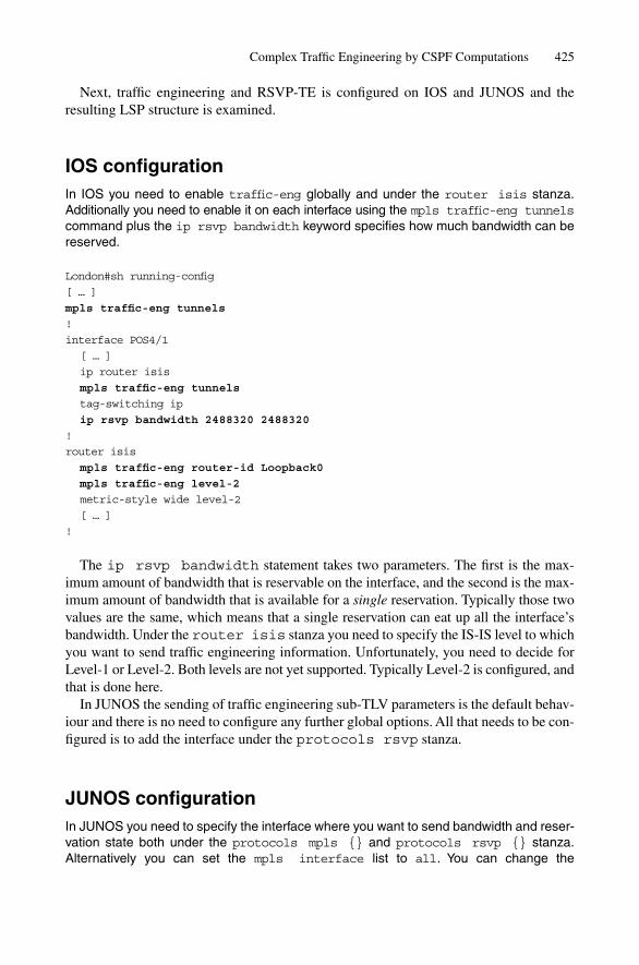
Complex Traffic Engineering by CSPF Computations 425
Next, traffic engineering and RSVP-TE is configured on IOS and JUNOS and theresulting LSP structure is examined.
IOS configurationIn IOS you need to enable traffic-eng globally and under the router isis stanza.Additionally you need to enable it on each interface using the mpls traffic-eng tunnelscommand plus the ip rsvp bandwidth keyword specifies how much bandwidth can bereserved.
London#sh running-config
[ … ]
mpls traffic-eng tunnels
!
interface POS4/1
[ … ]
ip router isis
mpls traffic-eng tunnels
tag-switching ip
ip rsvp bandwidth 2488320 2488320
!
router isis
mpls traffic-eng router-id Loopback0
mpls traffic-eng level-2
metric-style wide level-2
[ … ]
!
The ip rsvp bandwidth statement takes two parameters. The first is the max-imum amount of bandwidth that is reservable on the interface, and the second is the max-imum amount of bandwidth that is available for a single reservation. Typically those twovalues are the same, which means that a single reservation can eat up all the interface’sbandwidth. Under the router isis stanza you need to specify the IS-IS level to whichyou want to send traffic engineering information. Unfortunately, you need to decide forLevel-1 or Level-2. Both levels are not yet supported. Typically Level-2 is configured, andthat is done here.
In JUNOS the sending of traffic engineering sub-TLV parameters is the default behav-iour and there is no need to configure any further global options. All that needs to be con-figured is to add the interface under the protocols rsvp stanza.
JUNOS configurationIn JUNOS you need to specify the interface where you want to send bandwidth and reser-vation state both under the protocols mpls {} and protocols rsvp {} stanza.Alternatively you can set the mpls interface list to all. You can change the

426 14. Traffic Engineering and MPLS
oversubscription of RSVP bandwidth by changing the default value of 100% using thesubscription keyword.
hannes@Frankfurt# show
[ … ]
protocols {
mpls {
interface all;
}
rsvp {
interface so-0/1/2.0 {
subscription 120;
}
}
}
[ … ]
As soon as you enable RSVP-TE on an interface on which the router has establishedan adjacency, then the LSP gets updated with a lot of extra information, encoded byadding several sub-TLVs to the extended IS Reachability TLV #22.
Tcpdump outputAn RSVP-TE enabled IS-IS adjacency shows the interface speed plus current reservationstate using 8 pre-emption classes.
00:28:20.760649 OSI, IS-IS, length: 156
hlen: 27, v: 1, pdu-v: 1, sys-id-len: 6 (0), max-area: 3 (0), pdu-type: L2 LSP
lsp-id: 0620.0000.0001.00-00, seq: 0x00000031, lifetime: 1196s
chksum: 0x2674 (correct), PDU length: 156, L1L2 IS
Area address(es) TLV #1, length: 4
Area address (length: 3): 49.0001
Protocols supported TLV #129, length: 1
NLPID(s): IPv4
Traffic Engineering Router ID TLV #134, length: 4
Traffic Engineering Router ID: 62.0.0.1
IPv4 Interface address(es) TLV #132, length: 4
IPv4 interface address: 62.0.0.1
Hostname TLV #137, length: 9
Hostname: Frankfurt
Extended IS Reachability TLV #22, length: 75
IS Neighbor: 0621.5401.3008.00, Metric: 10, sub-TLVs present (64)
IPv4 interface address subTLV #6, length: 4, 10.0.0.2
IPv4 neighbor address subTLV #8, length: 4, 10.0.0.1
Unreserved bandwidth subTLV #11, length: 32
priority level 0: 2488.320 Mbps
priority level 1: 2488.320 Mbps
priority level 2: 2488.320 Mbps
priority level 3: 2488.320 Mbps

Complex Traffic Engineering by CSPF Computations 427
priority level 4: 2488.320 Mbps
priority level 5: 2488.320 Mbps
priority level 6: 2488.320 Mbps
priority level 7: 2488.320 Mbps
Reservable link bandwidth subTLV #10, length: 4, 2488.320 Mbps
Maximum link bandwidth subTLV #9, length: 4, 2488.320 Mbps
Administrative groups subTLV #3, length: 4, 0x00000000
Extended IPv4 Reachability TLV #135, length: 18
IPv4 prefix: 62.0.0.1/32, Distribution: up, Metric: 0
IPv4 prefix: 10.0.0.0/30, Distribution: up, Metric: 10
Figure 14.17 shows the contents of the Traffic Engineering Router ID TLV #134. Itbasically contains a single unique 32-bit ID in order to uniquely identify a router in theTED. The TE Router ID TLV #134 corresponds to the OSPF Router-ID and puts thetopology gathered by the two protocols into a relationship in the TED. The underlyingproblem is that IS-IS identifies its nodes through System-IDs (48-bit) and OSPF does itusing Router-IDs (32-bit). By issuing a TLV #134 the IS-IS speaker tells other routerswhat would be the corresponding OSPF router-ID in case one router is running bothOSPF and IS-IS for transition purposes.
In Table 14.2 there is a list of sub-TLVs to the extended Reachability TLV #22. Theseare used for conveying various pieces of link information like Admin (Affinity) Groups,bandwidth parameters and IPv4 endpoint addresses. Chapter 11 “TLVs and Sub-TLVs”explores more about TLVs and sub-TLV nesting.
TLV Type
TLV Length
Traffic engineering router ID
132
Bytes
1
1
4
4
FIGURE 14.17. The Traffic Engineering TLV #134 contains a unique ID which identifies a TEspeaker throughout disjoint TE domains
TABLE 14.2. Sub-TLV code points.Sub-TLV Sub-TLV name
3 Administrative (Affinity) Group4 Link Local ID5 Link Remote ID6 IPV4 Interface Address8 IPV4 Remote Interface Address9 Maximum Link Bandwidth
10 Reserve Able Bandwidth11 Unreserved Bandwidth18 TE-Metric20 Link Protection Type (GMPLS)21 Switching Capability (GMPLS)Not yet assigned by IANA Bandwidth Constraints

428 14. Traffic Engineering and MPLS
After the TED has been populated with the above link-related information, the routersengage in a CSPF calculation based on the network operator’s constraints. The CSPF isa two-pass calculation where in the first pass all the links that do not fit a certain con-straint are removed, and the second pass is a vanilla SPF calculation as was described inChapter 10, “SPF and Route Calculation”.
See Figure 14.18 for an example of CSPF. The network needs to compute a labelswitched path between Washington and New York which can only run on links carrying the “Internet” Link Colour (Affinity Group) and must not run on links carrying the“Maintenance” Link Colour (Affinity Group). The amount of reserved bandwidth is600 MBit/s. In the first pass of the CSPF calculation all the links that do not belong to therequired “Internet” administrative group are removed. The direct link between Washingtonand New York does not fit the constraint because it carries the “Maintenance” Link Colour.Next, all the links that do not have sufficient bandwidth are removed. The reservation ofadditional 600 MBit/s would oversubscribe the link between Washington and Frankfurt andis removed as well.
Based on the resulting “skeleton”, the routers run an SPF calculation and try to find theshortest path node between the source and the destination point. In our example, the pathvia Paris, Frankfurt and London fits all the constraints and therefore the tunnel comes up.The result of the SPF calculation does not really matter because in this case there is onlya single path left which fulfils all constraints.
If there are too many constraints during the first pass and there are no feasible paths atall, then the result of the SPF calculation will be that there is no shortest path between apair of nodes. Note that in CSPF calculations, there is not any type of crank-back proced-ure where the systems try to find a path at all costs. This was common practice for voicenetworks, but crank-back schemes run the risk of sending traffic around the continent sev-eral times, like the overlay networks of the 1990s did. Sometimes the result of the CSPFcalculation is even no result at all and then no tunnel will be signalled.
14.6 LDP over RSVP-TE Tunnelling
Which signalling protocol (LDP or RSVP-TE) to use is one of the first questions that net-work operators raise when deploying MPLS. Many people like the “call-oriented” notionof RSVP-TE and the amount of control the network operator has over traffic. On the otherhand, LDP works like a charm – you turn it on and seconds later you have got labelswitched paths to every corner of your network at almost no cost and with nice scalingproperties. To achieve the same connectivity matrix that LDP creates, one would have todeploy RSVP-TE in a full-mesh fashion with a dedicated tunnel between all the MPLSedge routers. In moderate size networks full-mesh RSVP-TE may be a design choice, how-ever, in medium-to large-sized networks, this may be a scaling nightmare. Recall that in afull-mesh network with 1000 edge routers, one would need 1000 * (1000 – 1)/2 � 499,500label switched paths! The refresh noise alone from repeating each reservation every 30 sec-onds, which will be processed twice (PATH and RESV messages from all the core routersalong the label switched path), would result in approximately 30,000 messages per secondbeing processed by each core router. Although there are extensions to aggregate refreshes

LDP over RSVP-TE Tunnelling 429
0 MBit/s rsvd.
Internet, Maintenance400 MBit/s rsvd.
Internet
280 MBit/s rsvd.
Internet
1900 MBit/s rsvd.
Internet
1250 MBit/s rsvd.
Internet
1100 MBit/s rsvd.
Internet
4
4
6
4
4
4
400 MBit/s rsvd.
Internet
280 MBit/s rsvd.
Internet
1900 MBit/s rsvd.
Internet
1250 MBit/s rsvd.
Internet
1100 MBit/s rsvd.
Internet
4
4
4
4
4
Prune all links that do not have Internet and Maintenance set1
Prune all links that do not fit Bandwidth requirements2
280 MBit/s rsvd.
Internet
4 4
1100 MBit/s rsvd.
Internet
4
1250 MBit/s rsvd.
Internet
Frankfurt
London
Washington New York
Paris
Frankfurt
London
Washington New York
Paris
Frankfurt
London
Washington New York
Paris
400 MBit/s rsvd.
Internet
4
FIGURE 14.18. In the CSPF calculation all paths that do not meet any of the constraints are prunedoff the final topology

430 14. Traffic Engineering and MPLS
LDP
RSVP
POP
POP
POP
POP POP
LDP over RSVP tunneling3
Frankfurt
London
Washington NewYork
Paris
TE Tunnel 2
1
FIGURE 14.19. Traffic from Paris to London does not take the TE tunnel path
(see RFC 2961 for details), and thereby reduce the refresh noise, the underlying problem(which is the familiar networking “N^2” problem) is not addressed by aggregation alone.For scalability reasons, network operators are tempted to use the more scaleable LDP,which sets up a kind of full-mesh matrix (based on sink trees). But LDP label selection isdictated by the IGP, and that translates to a lack of traffic path-control because no one wantsto tweak IGP metrics anymore.
So the answer to the signalling protocol question is most often to use both protocolswhere they fit best. LDP is used for setting up lightweight labels switched paths acrossthe network, and RSVP-TE is used for traffic engineering.
Consider Figure 14.19, where both protocols are deployed. LDP is deployed acrossthe core for establishing label switched paths between all routers in the network (1).Additionally, there is a Traffic Engineering Tunnel between the core router in Paris andLondon (2). If traffic is loaded on that path, then all the traffic will be guided throughLDP paths and the single RSVP-TE TE tunnel in the core is completely ignored. Why?Because MPLS is a source routing technique. The ingress router makes the choice as towhich label switched path is used for traffic forwarding. If an edge (ingress) router doesnot know about a TE tunnel path in the core, then it will not use it.
The trick is now to make LDP use the TE tunnel in the core for forwarding. A tech-nique called LDP over RSVP-TE tunnelling is used for that purpose. Previously, LDPwas deployed in a hop-by-hop fashion – the LDP speakers propagate their label mappingmessages from node to adjacent node. In order to make LDP use the TE tunnel, an add-itional LDP session is brought up between the Paris and London core router (3). For set-ting up a session between a pair of non-adjacent routers, an LDP option called targetedHellos is used. Targeted Hellos are similar to internal BGP sessions. The two LDP speak-ers at the edge send a Hello across several hops. If the two speakers at the edge agree onthe capabilities reported in the Hello message, then an LDP session (using TCP) is estab-lished to advertise label mappings. All label advertisements learned via the multi-hop

LDP over RSVP-TE Tunnelling 431
LDP session are now associated with the TE tunnel and then used for traffic forwarding.When Paris advertises a label back to its local POP routers, then a SWAP/PUSH state onthe forwarding plane is generated. The label of the TE tunnel is PUSHed as top levellabel and the label learned via the multi-hop LDP session is the SWAPed label. The edgerouters send their traffic down the LDP established paths and do not even know that theirtraffic is being engineered in the core topology. As soon as the traffic arrives at theingress of the TE tunnel (Paris), an additional label is PUSHed on top of the label stackand the traffic is sent down the TE tunnel. The penultimate TE tunnel router (New York)removes the top label and the LDP label underneath becomes visible and is used for fur-ther relaying traffic towards the LDP egress router.
Configuration of LDP over RSVP-TE tunnelling is done using the mpls ldpneighbor <address> targeted ldp keyword in IOS and the ldp-tunnelingkeyword in JUNOS.
IOS configurationIn IOS LDP tunnelling is a global option which can be configured using the mpls ldpneighbor <address> targeted statement.
London# show running-config
[ … ]
mpls ldp neighbor 192.168.1.1 targeted ldp
[ … ]
!
If the multi-hop LDP session comes up and there is an RSVP-TE tunnel to this des-tination, then the resolver will automatically set up the SWAP/PUSH state. In JUNOSLDP over RSVP-TE tunnelling is a property of the TE tunnel and is configured under theprotocols mpls label-switched-path <name> {} stanza.
JUNOS configurationIn JUNOS the ldp-tunneling keyword automatically sets up a session between twoends of a TE tunnel.
[edit]
hannes@Frankfurt# show
[ … ]
protocols {
mpls {
label-switched-path to-London {
to 192.168.0.8;
ldp-tunneling;
}
interface so-1/2/0;
interface l00.0;
}
[ … ]
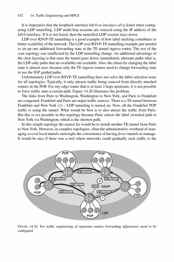
432 14. Traffic Engineering and MPLS
It is imperative that the loopback interface lo0.0 or interface all is listed when config-uring LDP tunnelling. LDP multi-hop sessions are sourced using the IP address of thelo0.0 interface. If it is not listed, then the tunnelled LDP session stays down.
LDP over RSVP-TE tunnelling is a good example of how label stacking contributes tobetter scalability of the network. The LDP over RSVP-TE tunnelling example just neededto set up one additional forwarding state at the TE tunnel ingress router. The rest of thecore topology was unaffected by the LDP tunnelling change. An additional advantage ofthe clear layering is that once the tunnel goes down, immediately alternate paths (that is,the LDP-only paths that are available) are available. Also, the churn for changing the labelstate is almost zero, because only the TE ingress routers need to change forwarding stateto use the IGP guided paths.
Unfortunately LDP over RSVP-TE tunnelling does not solve the label selection issuefor all topologies. Typically, it only attracts traffic being sourced from directly attachedrouters in the POP. For any edge router that is at least 2 hops upstream, it is not possibleto force traffic onto a certain path. Figure 14.20 illustrates the problem.
The links from Paris to Washington, Washington to New York, and Paris to Frankfurtare congested. Frankfurt and Paris are major traffic sources. There is a TE tunnel betweenFrankfurt and New York (1) – LDP tunneling is turned on. Now, all the Frankfurt POPtraffic is using the tunnel. What would be best is to also attract the traffic from Paris. But this is not possible in this topology because Paris selects the label switched path toNew York via Washington, which is the shortest path.
In this simple topology the easiest fix would be to install another TE tunnel from Paristo New York. However, in complex topologies, often the administrative overhead of man-aging several local tunnels outweighs the convenience of having fewer tunnels to manage.It would be nice if there was a tool where networks could gradually suck traffic to the
RSVP
2
1
LDP
POP
POP
POP
POP POP
Frankfurt
London
Washington NewYork
Paris
120% load
95% load
25% load4
4
4
6
4
1-10
30% load
20% load
110% load42
FIGURE 14.20. For traffic engineering of upstream routers forwarding adjacencies need to beconfigured

LDP over RSVP-TE Tunnelling 433
head-end of a TE tunnel. But to affect non-local forwarding decisions, the network needsto find a way to modify the route computation. And there is one. Forwarding adjacenciesare a way of re-advertising a label switched path in the IS-IS database.
14.7 Forwarding Adjacencies
The Edge MPLS routers, which speak LDP, have to rely on the IGP (IS-IS) to find theshortest path to the destination. Recall that the general problem of traffic engineering is thatthe shortest path is not always the best path. The tunnel must be made somewhat attractiveto the edge systems’ traffic. One way of doing this is to model the core TE tunnel as a directlink and make the tunnels cost a little better than the resulting IGP cost. Because of thatslight difference, the edge systems will prefer to load traffic onto the tunnel.
A decade ago it was common to run IGPs over a tunnel. But running dynamic routingprotocols over a tunnel is almost always a recipe for disaster. Things behave really badlyif the total IGP cost over the tunnel undermines the total topologies’ cost. What happensnext is that the tunnel “wraps” around itself, ultimately causing a meltdown of the entirenetwork. Having those glorious meltdowns in mind, designers put a few restrictions on re-advertising a TE tunnel as part of the IS-IS topology. First of all, no IS-IS Hellos are sentdown a tunnel. The router considers this forwarding adjacency to be up when the tunnel isup. If there is a change in topology and the tunnel goes down, then the forwarding adja-cency will go down as well. Because no Hellos are sent down the tunnel there is no infin-ite recursion problem as there was when tunnelling IGPs in the 1990s. Still, there aresome things to watch out for. If the cost of the forwarding adjacency becomes too low(that is, more attractive to the rest of the topology) then too much traffic is sucked towardsthat tunnel. This could even totally mess up the IGP routing.
Reconsider Figure 14.20. If the TE tunnel is advertised with IS reach information inthe IS-IS database, then it seems as if there is now a direct, additional link betweenFrankfurt and New York (2). The nice thing is that the metric of this “virtual” adjacencycan be configured arbitrarily. It can be set to a metric of 10, which makes the link totallyunattractive because there are shorter paths available. However, if the forwarding adja-cency metric is set (for instance) to 1, then even non-local traffic is sucked into the tun-nel, including all the POP traffic from (for example) Paris. Depending on the IGP metricdesign, the power of forwarding adjacencies can do severe damage to the network.Consider the IGP metric proposal in Figure 12.10. A metric of 1 is not used today, mainlyto leave some headroom for high speed links like OC768/STM-256 pipes. But if theadvertised metric of the tunnel is 1, even regional traffic between cities can be suckedacross the Atlantic. A common design rule is to keep the IGP cost slightly above the costof the real topology, and it should not exceed the typical link-metric inside the POP. Theidea is to suck the entire POP destinations across the tunnel, but keep the sucking-distance low enough not to affect other region’s traffic.
In IOS forwarding adjacencies are a property of a TE tunnel and can be configuredusing the tunnel mpls traffic-eng forwarding-adjacency parameter inthe tunnel interface configuration.

434 14. Traffic Engineering and MPLS
IOS configurationIn IOS you need to tell the tunnel interface that it has to re-advertise the TE tunnel into IS-IS using the tunnel mpls traffic-eng forwarding-adjacency statement.Additionally the resulting IS-IS metric needs to be specified using the regular isismetric <*> statement.
London# show running-config
[ … ]
interface Tunnel0
mpls traffic-eng tunnels
tag-switching ip
tunnel mode mpls traffic-eng
tunnel mpls traffic-eng forwarding-adjacency
isis metric 200 level-2
!
In JUNOS, a forwarding adjacency is an IS-IS property and is configured under theprotocols isis label-switched-path {} stanza.
JUNOS configurationIn JUNOS you need to reference a valid label switched path which needs to exist underthe protocols mpls {} stanza plus the IS-IS level and metric.
hannes@Frankfurt> show configuration
[ … ]
protocols {
isis {
[ … ]
label-switched-path Paris-to-London {
level 2 metric 200;
}
}
}
[ … ]
How do the other routers know that an IS-IS adjacency is real (over physical links) or theresult of a forwarding adjacency (over a TE tunnel)? In order not to run into recursive tun-nel loop problems, there is a differentiation. If you consider the tcpdump output, then youcan easily see the difference between a physical link adjacency and a forwarding adjacency.
Tcpdump outputA forwarding adjacency enabled IS reachability information does not carry any traffic engi-neering sub-TLVs.

00:28:20.760649 OSI, IS-IS, length: 156
hlen: 27, v: 1, pdu-v: 1, sys-id-len: 6 (0), max-area: 3 (0), pdu-type: L2 LSP
lsp-id: 1921.6800.1014.00-00, seq: 0x0000df31, lifetime: 1196s
chksum: 0x2674 (correct), PDU length: 156, L1L2 IS
[ … ]
Hostname TLV #137, length: 5
Hostname: Paris
Extended IS Reachability TLV #22, length: 86
physical link → IS Neighbor: 1921.6800.1008.00, Metric: 10, sub-TLVs present (64)IPv4 interface address subTLV #6, length: 4, 172.16.0.2
IPv4 neighbor address subTLV #8, length: 4, 172.16.0.1
Unreserved bandwidth subTLV #11, length: 32
priority level 0: 2488.320 Mbps
priority level 1: 2488.320 Mbps
priority level 2: 2488.320 Mbps
priority level 3: 2488.320 Mbps
priority level 4: 2488.320 Mbps
priority level 5: 2488.320 Mbps
priority level 6: 2488.320 Mbps
priority level 7: 2488.320 Mbps
Reservable link bandwidth subTLV #10, length: 4, 2488.320 Mbps
Maximum link bandwidth subTLV #9, length: 4, 2488.320 Mbps
Administrative groups subTLV #3, length: 4, 0x00000000
Forw. Adjacency → IS Neighbor: 1921.6800.1012.00, Metric: 200, no sub-TLVs presentExtended IPv4 Reachability TLV #135, length: 18
IPv4 prefix: 62.0.0.1/32, Distribution: up, Metric: 0
IPv4 prefix: 172.16.0.0/30, Distribution: up, Metric: 10
The forwarding adjacency gets advertised as simply Extended IS Reach Adjacencywith no sub-TLVs at all attached to it. Therefore, the adjacency does not get moved to theTED. It is almost as if this virtual “link” does not exist for the TED. If a link does not existin the TED, then no adjacency can be established over it, and the tunnel recursion prob-lem is fixed. One of the key concepts of forwarding adjacencies is that the resulting vir-tual link should always be worse than a real link. Chapter 17, “Future of IS-IS”, willextend the forwarding adjacency concept to several switching layers and examine howforwarding adjacencies can be utilized for G-MPLS applications.
Forwarding adjacencies are a nice tool to offload traffic from the shortest path withminimal configuration and maximum impact. However, one problem remains: if thepath’s physical characteristics change, the delay characteristics of that path may alsochange. In order to modify traffic paths for only some classes of traffic, DiffServ TrafficEngineering needs to be deployed.
14.8 DiffServ Aware Traffic Engineering
Originally, traffic engineering was used to offload just best-effort traffic. This was fine,because at that time, only best-effort traffic was routed. In recent years, however, there has
Forwarding Adjacencies 435
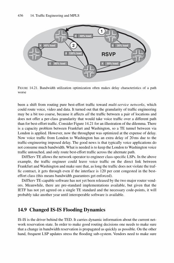
been a shift from routing pure best-effort traffic toward multi-service networks, whichcould route voice, video and data. It turned out that the granularity of traffic engineeringmay be a bit too coarse, because it affects all the traffic between a pair of locations anddoes not offer a per-class granularity that would take voice traffic over a different paththan for best-effort traffic. Consider Figure 14.21 for an illustration of the dilemma. Thereis a capacity problem between Frankfurt and Washington, so a TE tunnel between viaLondon is applied. However, now the throughput was optimized at the expense of delay.Now voice traffic from London to Washington has an extra delay of 20 ms due to thetraffic-engineering imposed delay. The good news is that typically voice applications donot consume much bandwidth. What is needed is to keep the London to Washington voicetraffic untouched, and only route best-effort traffic across the alternate path.
DiffServ TE allows the network operator to engineer class-specific LSPs. In the aboveexample, the traffic engineer could leave voice traffic on the direct link betweenFrankfurt and Washington and make sure that, as long the traffic does not violate the traf-fic contract, it gets through even if the interface is 120 per cent congested in the best-effort class (this means bandwidth guarantees get enforced).
DiffServ TE-capable software has not yet been released by the two major router vend-ors. Meanwhile, there are pre-standard implementations available, but given that theIETF has not yet agreed on a single TE standard and the necessary code-points, it willprobably take another year until interoperable software is available.
14.9 Changed IS-IS Flooding Dynamics
IS-IS is the driver behind the TED. It carries dynamic information about the current net-work reservation state. In order to make good routing decisions one needs to make surethat a change in bandwidth reservation is propagated as quickly as possible. On the otherhand, frequent LSP updates stress the flooding sub-system. Vendors need to make sure
436 14. Traffic Engineering and MPLS
RSVP
45% load
40% load
30% load
80% load4
4
4
6
4
120% load4
20% load
Frankfurt
London
Washington NewYork
Paris
1
2
FIGURE 14.21. Bandwidth utilization optimization often makes delay characteristics of a pathworse

that in the event of many LSPs flapping (down/up), the update in reservation does notchurn the network. JUNOS and IOS support throttling mechanisms in order to hold downquick reservation changes. In IOS, those throttling timers are configurable on a per inter-face basis.
JUNOS Configuration SnippetIn JUNOS the update-threshold parameter to control IGP updates based on reservationis a function of the rsvp interface {} stanza.
hannes@Frankfurt# show configuration
[ … ]
protocols {
rsvp {
interface so-7/0/0.0 {
update-threshold 10;
}
}
}
You can verify your setting by issuing the show rsvp interface <if-name> detail command.
14.10 Conclusion
IS-IS has become far more than just an IP routing protocol. It is now being used for trafficengineering purposes by sending a lot of extra topology-related information like band-width, link colours and additional TE metrics. All this information is conveyed using sub-TLVs to the Extended IS Reach TLV #22 and stored in a unified form in the TED. Basedon the TED contents, Explicit Route Objects (ERO) are pre-determined, which will then beembedded in RSVP-TE path messages. The calculations are done using a CSPF calculation,which is a modified version of the SPF algorithm. The constrained SPF algorithm firstprunes off links that do not follow certain constraints before doing a regular SPF. Settingup just the tunnel is not enough; one needs to care also about loading traffic on the tunnel.Re-advertising TE tunnels back into IS-IS is the way to attract enough traffic from otherhops further downstream from the head of the TE tunnel. Optimizing for the best networkutilization may not be desirable, especially for voice traffic, which requires low and stabledelays. DiffServ TE allows the calculation and setup of per-traffic-class tunnels for opti-mizing the different goals of each class: best-effort traffic is optimized for bandwidth utilization and voice traffic is optimized for the shortest delay. Changes in bandwidth reservations also cause an extra amount of LSP updates, which need to be taken intoaccount for assessing the overall scalability of large networks. Meanwhile, code supportingtraffic engineering has been in the field now for 3–4 years and is in a mature state now.DiffServ Traffic Engineering Code has not been deployed yet in production networks, butis expected to be the “Swiss Army knife” of traffic engineering, fulfilling the purpose forall traffic types.
DiffServ Aware Traffic Engineering 437
15
Troubleshooting
439
Now you know almost everything there is to know about IS-IS and you can go and con-figure it in your network. Seriously, IS-IS is quite easy to configure on router OSs. Mostlikely, a pair of routers will immediately start exchanging PDUs and then do an SPF cal-culation on the common set of entries in the IS-IS link-state database. If they don’t, well,just continue reading. This chapter is all about IS-IS troubleshooting. First, this chapterwill develop a common flowchart-like methodology that allows us to hunt down almostany IS-IS related problem. Next, the chapter explores the troubleshooting tools that areavailable on the router OS for gathering the information required by the troubleshootingmethodology. Finally, the chapter will end by exploring real-world case studies of IS-IS-related problems in the areas of adjacency management, database overloading, and SPFcalculations.
15.1 Methodology
Any good troubleshooting process starts with a step-by-step plan and an iterative comparison between the desired state of the network and the actual state. For example, itdoes not make sense to examine the contents of the link-state database if no adjacency isup to supply the LSDB with data. The starting assumption for this troubleshooting planof attack is that the router has a working physical circuit, free of bit errors and othertransmission-related faults.
Figure 15.1 illustrates a generic troubleshooting plan for IS-IS problems. The heart ofthe plan is an iterative comparison between results from the router’s observed operationto the intended behaviour, typically the behaviour defined in the configuration file. In theillustrations in this chapter, configuration-related information (what the router shouldbe doing) is indicated by light bubbles. Facts gathered from command outputs confirmswhat the router is actually doing, which is indicated by dark bubbles.
You start a troubleshooting session by verifying that adjacencies to other routers areup. If they are not, then there are three main sources of trouble. First, the problem couldbe related to the interface configuration (1). For example, an interface might not beincluded in the router’s IS-IS interface list or it carries wrong IS-IS level information.The problem could even be buried at lower layers in the OSI reference stack: too small aprotocol MTU or lack of OSI-CP support on point-to-point interfaces prevent IS-IS con-trol planes from exchanging any information. Next, a good place to look is the address-ing information like IPv4, IPv6 and OSI NLRIs. Most importantly, you first need to look

440 15. Troubleshooting
OK
OK
OK
TroubleshootingStart
Problemresolved
VerifyInterfaceConfig
VerifyAdjacency
Table
VerifyIPv4/IPv6/OSI
ProtocolConfig
VerifyTopology
Config
VerifyLink-StateDatabase
VerifyProtocol
PreferenceConfig
VerifySPF
results
VerifyAuthenti-
cationConfig
VerifyIP Routing
Table
1
2
3
4
FIGURE 15.1. At the heart of the troubleshooting process are iterations between comparisons ofconfiguration information and the actual state of the network

at the OSI router configuration, because that encompasses IS-IS Area- and System-IDconfiguration. If the System-ID and or Area-IDs are not configured, or wrongly defined,then any IS-IS network is condemned to failure. Unfortunately, adjacency managementis no longer a protocol-neutral function in IS-IS. Many IS-IS implementations require amatch for the IPv4 or IPv6 sub-nets in order to complete the IS-IS adjacency handshake.Also, a broken authentication configuration is a frequent reason why an adjacency doesnot come up.
The next major step is to check to see if the link-state database is filled with informa-tion (2). The major stumbling blocks here are duplicate System-IDs and mismatchedauthentication strings. After the router executes the SPF calculation, it shows you the cal-culated topology and the attached prefixes. If a node is missing in the SPF result list (3),we examine the link-state database to check for node isolation or unidirectional links andmay even spot a problem on a remote router in the network. In the age of multi-topologyIS-IS, it may be necessary to revisit the topology information and check to see if a giveninterface is in the required topology. A double check in the link-state database helps tospot missing IS Reachability Announcements and the like. If a node finally shows up in the SPF result list, and it has attached prefixes, those prefixes need to compete withprefixes from other routing protocols to become active routes. Because of its role as atopology discovery tool, IS-IS does not carry customer routes, but rather infrastructureroutes. So IS-IS routes are typically preferred to routes from other routing protocols likeBGP. However, in IOS, for example, external BGP paths have an administrative dis-tance, which has a route preference of 20 versus an IS-IS route that ranks only at distance115 of the route selection process. Particularly during routing protocol migrations (forexample from EIGRP to IS-IS) it may be the case that the other routing protocol is stillmasking the routes from the new routing protocol. A modification of the protocol prefer-ence configuration helps to unveil the IS-IS routes. If the IP routes finally show up in themain IP routing table, the troubleshooting process may end.
In our explanation of the troubleshooting process, we already mentioned two tools forinformation gathering: Examining the router configuration and looking at the output ofshow commands are important tools during the troubleshooting process. In the next sec-tion we will explore those tools and more, tools that help operators examine, understandand resolve IS-IS problems.
15.2 Tools
IS-IS troubleshooting quality and the accuracy of problem assessments is based on onemain factor: the tools that supply the network engineer with information. Based on theinformation derived from good tools, the network engineer makes a decision regardingthe parts of the configuration and the environment that are broken.
The first and most important troubleshooting tools are the show commands that therouter OS offers. Show command outputs are used on a daily basis and therefore it isimperative that each network engineer knows the meaning of each output field of thesecommands.
Tools 441
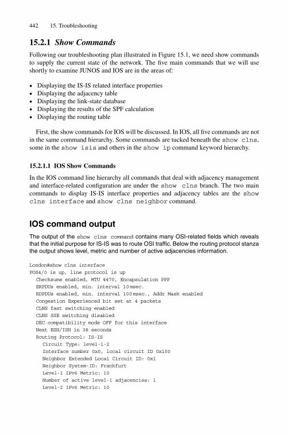
15.2.1 Show CommandsFollowing our troubleshooting plan illustrated in Figure 15.1, we need show commandsto supply the current state of the network. The five main commands that we will useshortly to examine JUNOS and IOS are in the areas of:
• Displaying the IS-IS related interface properties• Displaying the adjacency table• Displaying the link-state database• Displaying the results of the SPF calculation• Displaying the routing table
First, the show commands for IOS will be discussed. In IOS, all five commands are notin the same command hierarchy. Some commands are tucked beneath the show clns,some in the show isis and others in the show ip command keyword hierarchy.
15.2.1.1 IOS Show Commands
In the IOS command line hierarchy all commands that deal with adjacency managementand interface-related configuration are under the show clns branch. The two maincommands to display IS-IS interface properties and adjacency tables are the showclns interface and show clns neighbor command.
IOS command outputThe output of the show clns command contains many OSI-related fields which revealsthat the initial purpose for IS-IS was to route OSI traffic. Below the routing protocol stanzathe output shows level, metric and number of active adjacencies information.
London#show clns interface
POS4/0 is up, line protocol is up
Checksums enabled, MTU 4470, Encapsulation PPP
ERPDUs enabled, min. interval 10msec.
RDPDUs enabled, min. interval 100msec., Addr Mask enabled
Congestion Experienced bit set at 4 packets
CLNS fast switching enabled
CLNS SSE switching disabled
DEC compatibility mode OFF for this interface
Next ESH/ISH in 38 seconds
Routing Protocol: IS-IS
Circuit Type: level-1-2
Interface number 0x0, local circuit ID 0x100
Neighbor Extended Local Circuit ID: 0x1
Neighbor System-ID: Frankfurt
Level-1 IPv6 Metric: 10
Number of active level-1 adjacencies: 1
Level-2 IPv6 Metric: 10
442 15. Troubleshooting
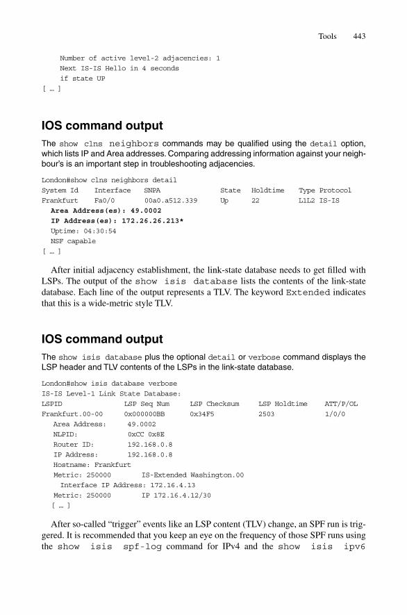
Number of active level-2 adjacencies: 1
Next IS-IS Hello in 4 seconds
if state UP
[ … ]
IOS command outputThe show clns neighbors commands may be qualified using the detail option,which lists IP and Area addresses. Comparing addressing information against your neigh-bour’s is an important step in troubleshooting adjacencies.
London#show clns neighbors detail
System Id Interface SNPA State Holdtime Type Protocol
Frankfurt Fa0/0 00a0.a512.339 Up 22 L1L2 IS-IS
Area Address(es): 49.0002
IP Address(es): 172.26.26.213*
Uptime: 04:30:54
NSF capable
[ … ]
After initial adjacency establishment, the link-state database needs to get filled withLSPs. The output of the show isis database lists the contents of the link-statedatabase. Each line of the output represents a TLV. The keyword Extended indicatesthat this is a wide-metric style TLV.
IOS command outputThe show isis database plus the optional detail or verbose command displays theLSP header and TLV contents of the LSPs in the link-state database.
London#show isis database verbose
IS-IS Level-1 Link State Database:
LSPID LSP Seq Num LSP Checksum LSP Holdtime ATT/P/OL
Frankfurt.00-00 0x000000BB 0x34F5 2503 1/0/0
Area Address: 49.0002
NLPID: 0xCC 0x8E
Router ID: 192.168.0.8
IP Address: 192.168.0.8
Hostname: Frankfurt
Metric: 250000 IS-Extended Washington.00
Interface IP Address: 172.16.4.13
Metric: 250000 IP 172.16.4.12/30
[ … ]
After so-called “trigger” events like an LSP content (TLV) change, an SPF run is trig-gered. It is recommended that you keep an eye on the frequency of those SPF runs usingthe show isis spf-log command for IPv4 and the show isis ipv6
Tools 443

spf-log command for IPv6. If there are no topology changes like metrics changes orlink flaps then you should only see the periodical SPF runs executed every 900 seconds(15 minutes).
IOS command outputIn a quiet environment without link flaps a periodic SPF run is triggered every 15 minutes.
London#show isis spf-log
IP level 1 SPF log
When Duration Nodes Count First trigger LSP Triggers
04:34:52 12 8 2 Frankfurt.00-00 ATTACHFLAG LSPHEADER
04:29:33 8 8 1 PERIODIC
04:14:30 0 8 1 PERIODIC
03:59:26 4 8 1 PERIODIC
03:44:25 4 8 1 PERIODIC
03:29:25 12 8 1 PERIODIC
03:14:24 12 8 1 PERIODIC
[ … ]
After the SPF calculation is finished a sorted list of nodes plus their associated neigh-bours (next-hops) is generated. The show isis topology command displays eachnode in the network plus the calculated cost to get there.
IOS command outputThe show isis topology output displays the result of the IPv4 calculation. The showisis ipv6 topology provides the results of the IPv6 calculation in case that multi topol-ogy has been deployed.
London#show isis topology
[ … ]
IS-IS IP paths to level-2 routers
System Id Metric Next-Hop Interface SNPA
Frankfurt 22000 Frankfurt POS4/0
Washington 272000 Frankfurt POS4/0
New York 294000 Frankfurt POS4/0
Pennsauken 315000 Pennsauken POS5/0
London —
[ … ]
The last step is to verify if the route in question has been inserted in the IP routing table.The output of the show ip route command shows if the IS-IS supplied route is thebest in the system. If it is not, then we need to adjust protocol preferences.
444 15. Troubleshooting

IOS command outputThe show ip route command displays all the contents of the IPv4 Unicast RoutingTable. Alternatively, you can append the isis qualifier to the commands, which displaysonly the IS-IS supplied routes.
London#show ip route
[ … ]
171.16.0.0/16 is variably subnetted, 2 subnets, 2 masks
i L2 171.16.33.0/29 [115/34] via 172.16.33.213, POS4/0
i L2 171.16.33.16/30 [115/18] via 172.16.33.213, POS4/0
172.16.33.0/24 is subnetted, 1 subnets
C 172.16.33.0 is directly connected, POS5/0
172.16.34.0/24 is variably subnetted, 16 subnets, 4 masks
i L2 172.16.34.8/30 [115/24] via 172.16.33.213, FastEthernet0/0
i L2 172.16.34.0/22 [115/34] via 172.16.33.213, FastEthernet0/0
i L1 172.16.34.12/30 [115/25] via 172.16.33.213, FastEthernet0/0
i L1 172.16.34.8/30 [115/15] via 172.16.33.213, FastEthernet0/0
JUNOS supplies similar command output to IOS.
15.2.1.2 JUNOS Show Commands
JUNOS does not carry any OSI forwarding legacy. As visible property of that “clean-sheet” design all the relevant IS-IS commands are under the show isis commandhierarchy. The two most important commands are again to display the current adjacencystate and the interface list with parameters.
JUNOS command outputThe show isis interface detail command displays all parameters of an IS-IS circuit.Optional qualifiers are the detail and extensive keyword. On a broadcast circuit thecommand additionally lists the designated router plus a hint if it’s us.
hannes@stockholm> show isis interface detail
IS-IS interface database:
e3-0/0/0.0
Index: 64, State: 0x46, Circuit id: 0x1, Circuit type: 2
LSP interval: 100ms, CSNP interval: 15s
Level Adjacencies Priority Metric Hello (s) Hold (s)
Designated Router
2 1 64 14 9.000 27
fe-0/3/3.0
Index: 69, State: 0x6, Circuit id: 0x2, Circuit type: 1
LSP interval: 100 ms, CSNP interval: 10 s
Level Adjacencies Priority Metric Hello (s) Hold (s)
Designated Router
1 1 64 5 3.000 9
Stockholm.02 (us)
Tools 445

The show isis adjacency command provides you with a list of the active adja-cencies on a given router. The optional command qualifiers detail and extensiveprovide more insight, such as a detailed property and timer breakdown plus an adjacencytransition table.
JUNOS command outputThe show isis adjacency command plus the optional detail and extensivequalifiers provide detailed addressing, topology and state machine output based on thecurrent Adjacency Table.
hannes@Frankfurt> show isis adjacency extensive
London
Interface: so-0/0/0.0, Level: 2, State: Up, Expires in 22secs
Priority: 0, Up/Down transitions: 3, Last transition: 3d 04:43:07 ago
Circuit type: 2, Speaks: IP, IPv6
Topologies: Unicast, IPV6-Unicast
IP addresses: 172.16.33.29
IPv6 addresses: fe80::203:fdff:fec8:3c00
Transition log:
When State Reason
Tue Nov 11 16:45:17 Up Seenself
Thu Nov 13 17:12:26 Down Interface Down
Thu Nov 13 17:13:04 Up Seenself
The output of the show isis database command lists the contents of the LSPheader and payload entries including a list of all the encoded TLVs.
JUNOS command outputThe output of the show isis database extensive gives a detailed breakdown on theLSP plus all associated internal timers like garbage collection and refresh.
hannes@Frankfurt> show isis database extensiveIS-IS level 2 link-state database:
Stockholm.02-00 Sequence: 0x13, Checksum: 0, Lifetime: 0 secs
Header: LSP ID: Stockholm.02-00, Length: 37 bytesAllocated length: 1492 bytes, Router ID: 192.168.0.17Remaining lifetime: 0 secs, Level: 2,Interface: 0Estimated free bytes: 1416, Actual free bytes: 1455Garbage collection timer expires in: 1116 secs
Packet: LSP ID: Stockholm.02-00, Length: 37 bytes, Lifetime : 0 secsChecksum: 0, Sequence: 0x13, Attributes: 0x3 <L1 L2>NLPID: 0x83, Fixed length: 27 bytes, Version: 1, Sysid length: 0 bytesPacket type: 20, Packet version: 1, Max area: 0
TLVs:Authentication data: 8 bytes
No queued transmissions
446 15. Troubleshooting
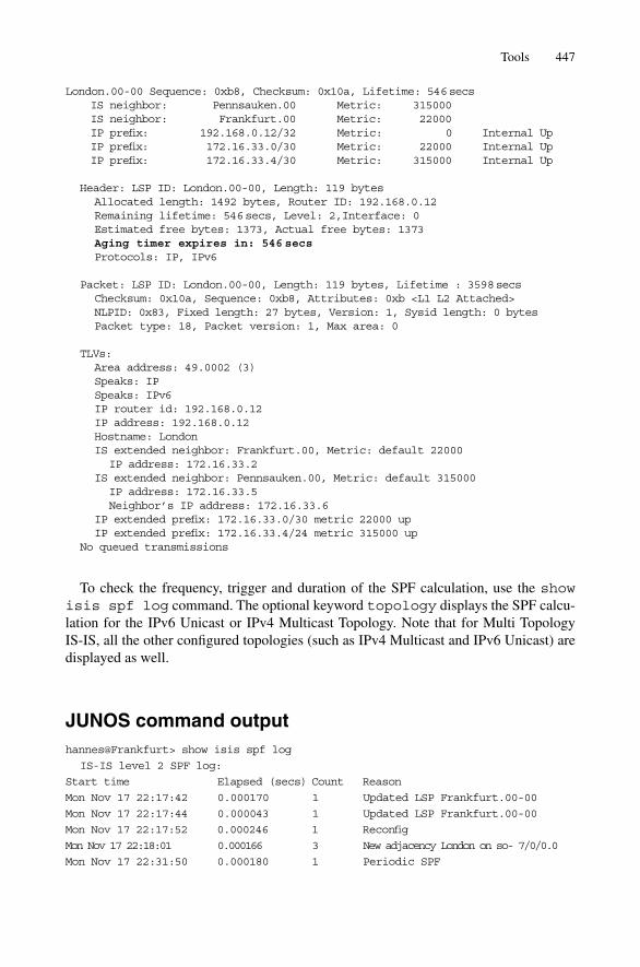
London.00-00 Sequence: 0xb8, Checksum: 0x10a, Lifetime: 546secsIS neighbor: Pennsauken.00 Metric: 315000IS neighbor: Frankfurt.00 Metric: 22000IP prefix: 192.168.0.12/32 Metric: 0 Internal UpIP prefix: 172.16.33.0/30 Metric: 22000 Internal UpIP prefix: 172.16.33.4/30 Metric: 315000 Internal Up
Header: LSP ID: London.00-00, Length: 119 bytesAllocated length: 1492 bytes, Router ID: 192.168.0.12Remaining lifetime: 546secs, Level: 2,Interface: 0Estimated free bytes: 1373, Actual free bytes: 1373Aging timer expires in: 546secsProtocols: IP, IPv6
Packet: LSP ID: London.00-00, Length: 119 bytes, Lifetime : 3598secsChecksum: 0x10a, Sequence: 0xb8, Attributes: 0xb <L1 L2 Attached>NLPID: 0x83, Fixed length: 27 bytes, Version: 1, Sysid length: 0 bytesPacket type: 18, Packet version: 1, Max area: 0
TLVs:Area address: 49.0002 (3)Speaks: IPSpeaks: IPv6IP router id: 192.168.0.12IP address: 192.168.0.12Hostname: LondonIS extended neighbor: Frankfurt.00, Metric: default 22000
IP address: 172.16.33.2IS extended neighbor: Pennsauken.00, Metric: default 315000
IP address: 172.16.33.5Neighbor’s IP address: 172.16.33.6
IP extended prefix: 172.16.33.0/30 metric 22000 upIP extended prefix: 172.16.33.4/24 metric 315000 up
No queued transmissions
To check the frequency, trigger and duration of the SPF calculation, use the showisis spf log command. The optional keyword topology displays the SPF calcu-lation for the IPv6 Unicast or IPv4 Multicast Topology. Note that for Multi Topology IS-IS, all the other configured topologies (such as IPv4 Multicast and IPv6 Unicast) aredisplayed as well.
JUNOS command outputhannes@Frankfurt> show isis spf log
IS-IS level 2 SPF log:
Start time Elapsed (secs) Count Reason
Mon Nov 17 22:17:42 0.000170 1 Updated LSP Frankfurt.00-00
Mon Nov 17 22:17:44 0.000043 1 Updated LSP Frankfurt.00-00
Mon Nov 17 22:17:52 0.000246 1 Reconfig
Mon Nov 17 22:18:01 0.000166 3 New adjacency London on so- 7/0/0.0
Mon Nov 17 22:31:50 0.000180 1 Periodic SPF
Tools 447

The output of the show isis spf results displays both the nodal as well asthe per-prefix result of the SPF calculation.
JUNOS command outputIn contrast to IOS, JUNOS also includes the per-prefix metrics in the output of the topo-logical results shown by the show isis spf results command. If Multi Topology isturned on, several SPF results are displayed.
hannes@Frankfurt> show isis spf results
IS-IS level 2 SPF results:
Node Metric Interface Via SNPA
London.00 22000 so-7/0/0.0 London
22000 192.168.0.12/32
22000 172.16.33.4/30
337000 172.16.33.12/30
Pennsauken.00 315000 so-7/1/0.100 Pennsauken
315000 192.168.0.17/32
341000 172.16.33.16/30
630000 172.16.33.24/30
[ … ]
14 nodes
The command for verifying if a route is present in the main routing tables is the showroute command. It displays both the IPv4 Unicast Routing Table (inet.0) as well as theIPv6 Unicast Routing Table (inet6.0).
JUNOS command outputhannes@Frankfurt> show route
inet.0: 48 destinations, 58 routes (48 active, 0 holddown, 0 hidden)
+ = Active Route, - = Last Active, * = Both
[ … ]
192.168.0.12/32 *[IS-IS/15] 04:51:45, metric 22000
> to 172.26.26.29 via so-7/0/0.0
172.16.33.0/30 *[IS-IS/18] 5d 10:42:00, metric 315000
> to 10.0.2.5 via so-7/1/0.0
192.168.0.19/32 *[IS-IS/18] 5d 10:44:05, metric 22200
> to 10.0.2.5 via so-7/1/0.0
172.16.33.16/30 *[IS-IS/18] 3d 04:52:56, metric 395000
> to 10.0.2.9 via so-7/1/0.0
172.16.33.20/30 *[IS-IS/15] 5d 11:25:08, metric 22000
> to 10.0.4.10 via so-7/1/0.0
[ … ]
448 15. Troubleshooting
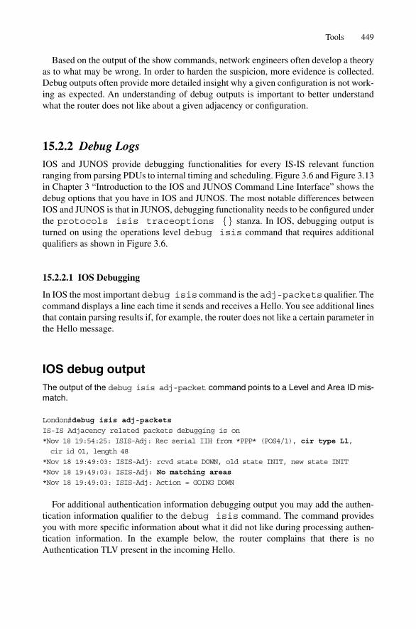
Based on the output of the show commands, network engineers often develop a theoryas to what may be wrong. In order to harden the suspicion, more evidence is collected.Debug outputs often provide more detailed insight why a given configuration is not work-ing as expected. An understanding of debug outputs is important to better understandwhat the router does not like about a given adjacency or configuration.
15.2.2 Debug LogsIOS and JUNOS provide debugging functionalities for every IS-IS relevant functionranging from parsing PDUs to internal timing and scheduling. Figure 3.6 and Figure 3.13in Chapter 3 “Introduction to the IOS and JUNOS Command Line Interface” shows thedebug options that you have in IOS and JUNOS. The most notable differences betweenIOS and JUNOS is that in JUNOS, debugging functionality needs to be configured underthe protocols isis traceoptions {} stanza. In IOS, debugging output isturned on using the operations level debug isis command that requires additionalqualifiers as shown in Figure 3.6.
15.2.2.1 IOS Debugging
In IOS the most important debug isis command is the adj-packets qualifier. Thecommand displays a line each time it sends and receives a Hello. You see additional linesthat contain parsing results if, for example, the router does not like a certain parameter inthe Hello message.
IOS debug outputThe output of the debug isis adj-packet command points to a Level and Area ID mis-match.
London#debug isis adj-packets
IS-IS Adjacency related packets debugging is on
*Nov 18 19:54:25: ISIS-Adj: Rec serial IIH from *PPP* (POS4/1), cir type L1,
cir id 01, length 48
*Nov 18 19:49:03: ISIS-Adj: rcvd state DOWN, old state INIT, new state INIT
*Nov 18 19:49:03: ISIS-Adj: No matching areas
*Nov 18 19:49:03: ISIS-Adj: Action = GOING DOWN
For additional authentication information debugging output you may add the authen-tication information qualifier to the debug isis command. The command providesyou with more specific information about what it did not like during processing authen-tication information. In the example below, the router complains that there is noAuthentication TLV present in the incoming Hello.
Tools 449

IOS debug outputLondon#debug isis adj-packets
IS-IS Adjacency related packets debugging is on
London#debug isis authentication information
IS-IS authentication information debugging is on
*Nov 19 22:56:48: ISIS-Adj: Rec serial IIH from *PPP* (POS4/1), cir type L1,
cir id 01, length 58
*Nov 19 22:56:48: ISIS-AuthInfo: No auth TLV found in received packet
*Nov 19 22:56:48: ISIS-Adj: Authentication failed
Once the adjacency has been established it is also interesting to check if the LSP dataexchange works and find out if Acknowledgements (PSNPs) are properly sent. The debugisis update-packets provides information about the parsing of LSP and buildingof PSNP packets.
IOS debug outputLondon#debug isis update-packets
IS-IS Update related packet debugging is on
*Nov 20 12:52:06: ISIS-Update: Rec L1 LSP 1921.6800.0021.00-00, seq 46, ht 65533,
*Nov 20 12:52:06: ISIS-Update: from SNPA *PPP* (POS4/1)
*Nov 20 12:52:06: ISIS-Update: LSP newer than database copy
*Nov 20 12:52:06: ISIS-Update: TLV code mismatch (2, 80)
*Nov 20 12:52:06: ISIS-Update: TLV code mismatch (2, 80)
*Nov 20 12:52:06: ISIS-Update: TLV contents different, code 0x2
*Nov 20 12:52:06: ISIS-Update: TLV code mismatch (16, 87)
*Nov 20 12:52:06: ISIS-Update: TLV contents different, code 0x16
*Nov 20 12:52:06: ISIS-Update: TLV code mismatch (80, 2)
*Nov 20 12:52:06: ISIS-Update: TLV contents different, code 0x80
*Nov 20 12:52:06: ISIS-Update: TLV code mismatch (87, 16)
*Nov 20 12:52:06: ISIS-Update: TLV contents different, code 0x87
*Nov 20 12:52:06: ISIS-Update: full SPF required
*Nov 20 12:52:06: ISIS-Update: IPv6 no change
*Nov 20 12:52:07: ISIS-Update: Build L1 PSNP entry for 1921.6800.0021-00, seq 46
*Nov 20 12:52:07: ISIS-Update: Sending L1 PSNP on POS4/1
15.2.2.2 JUNOS Debugging
JUNOS reveals its debugging output indirectly. You first need to configure the events youare interested in using the flag keyword underneath the protocols isis traceop-tions {} stanza. The output is then written to a file which can be specified using thefile qualifier.
JUNOS configurationIn JUNOS the flag keyword determines the amount of information that is written into theisis-trace.log file.
450 15. Troubleshooting

hannes@Frankfurt> show configuration
[ … ]
protocols {
isis {
file isis-trace.log size 1m microsecond-stamp;
flag lsp receive detail;
flag lsp-generation detail;
flag error;
flag hello detail;
flag csn detail;
flag psn detail;
}
}
}
You can specify a further qualifier after each flag. The receive or send qualifierlets you control the output of the debug log depending on the packets direction. Theoptional detail qualifier makes the output very verbose by giving you TLV and sub-TLVdetails. JUNOS offers you a nice tool when, for example, debugging LSP specificproperties – you can differentiate between self-originated LSPs and LSPs that you floodfurther. The above combination of the lsp receive detail and lsp-generationdetail knob does the trick. It displays all incoming LSPs and suppresses unnecessaryoutput once it floods it out on every core-facing interface (which can involve massiveoutput). On the other hand, outgoing self-originated LSPs are indeed interesting. IfJUNOS would just trace down LSPs and not make the differentiation between self-originated and flooded, then your debug file would get overwhelmed after a LSP storm.If you want to see a detailed breakdown of all the packets, then just setting the flagpackets detail can replace the lsp, hello, csn, psn flags.
JUNOS debug outputThe detail qualifier after each flag in the JUNOS traceoptions generates a wealth ofinformation. You can see the TLV contents of an outgoing Hello message plus the TLVLength of a Level 1 LSP build.
hannes@Frankfurt> monitor start isis-trace.log
*** isis-trace.log ***
Nov 20 18:47:03.340358 Sending P2P IIH on so-0/0/0.0
Nov 20 18:47:03.340431 max area 0, circuit type l1l2
Nov 20 18:47:03.340463 hold time 27, circuit id 0x01
Nov 20 18:47:03.340490 neighbor 0:2:b3:2b:e:7
Nov 20 18:47:03.340513 neighbor 0:2:b3:2b:e:52
Nov 20 18:47:03.340537 speaks IP
Nov 20 18:47:03.340557 speaks IPv6
Nov 20 18:47:03.340583 IP address 172.16.33.236
Nov 20 18:47:03.340617 IPv6 address fe80::7777:69ff: fea0:8002
Nov 20 18:47:03.340650 area address 49.0001 (3)
Tools 451

Nov 20 18:47:03.340680 restart RR reset RA reset holdtime 0
Nov 20 18:47:03.340711 1386 bytes of total padding
Nov 20 18:47:03.340752 checksum 0x6b7f
Nov 20 18:47:03.360591 Rebuilding L1 fragment Frankfurt.00-00, sequence 0x69
Nov 20 18:47:03.361195 Rebuilding LSP Frankfurt.00-00, free bytes 1320
Nov 20 18:47:03.361310 Next type: 1, estimated free bytes 1455,
free bytes 1455
Nov 20 18:47:03.361463 Next type: 129, estimated free bytes 1449,
free bytes 1449
Nov 20 18:47:03.361795 Next type: 134, estimated free bytes 1445,
free bytes 1445
Nov 20 18:47:03.361880 Next type: 137, estimated free bytes 1433,
free bytes 1433
Nov 20 18:47:03.362003 Next type: 22, estimated free bytes 1424,
free bytes 1424
Nov 20 18:47:03.362100 Next type: 128, estimated free bytes 1353,
free bytes 1353
Nov 20 18:47:03.362149 IP TLVs generated, used 29 bytes
Nov 20 18:47:03.362195 Rebuilt L1 fragment Frankfurt.00-00, size 168
After acquiring an understanding of what the network is doing wrong, perhaps the pre-requisite for further troubleshooting is to know what the network is supposed to do. Assuch, you need to know where the router keeps IS-IS-related configurations and how tomodify them.
15.2.3 Configuration FileThe IS-IS-related configuration is scattered across many places in a router configuration.There is interface related configuration, router process related configuration, authentica-tion information and finally routing-policies, route-maps and access-lists that deal withprefix exchange with other protocols.
In IOS most of the relevant IS-IS configuration is accommodated in the routerisis and interface section. Authentication information (key chains) is present inthe top level context and policies are defined as route-maps. In the configuration out-put below you can see an example of a full-blown IOS IS-IS configuration.
IOS configurationIn the IOS configuration most command parameters are set in the interface and routerisis command hierarchy. Policies are defined inside route-maps and access-lists.The Authentication strings are stored within a key chain. Static host-name mapping isstored at the end of the configuration file underneath the clns host prefix.
London#show running-config
[ … ]
key chain MY-SECRET-KEYSTRING
key 100
key-string 7 0702244B4F0F16171417
452 15. Troubleshooting

!
interface FastEthernet0/0
ip address 172.16.33.29 255.255.255.252
ip router isis
ipv6 router isis
[ … ]
isis authentication mode md5
isis authentication key-chain MY-SECRET-KEYSTRING
isis network point-to-point
isis three-way-handshake ietf
!
router isis
net 49.0002.1720.2602.6029.00
authentication mode md5 level-2
authentication key-chain MY-SECRET-KEYSTRING level-2
metric-style wide
passive-interface Loopback0
redistribute level-2 route-map isis_leak
!
address-family ipv6
multi-topology
exit-address-family
!
access-list 1 permit 192.168.0.0 0.0.0.255
access-list 1 deny any
!
route-map isis_leak permit 1
match ip route-source 1
!
clns host London 00.1921.6800.1019.00
[ … ]
The JUNOS configuration file follows a slightly different logic. Most notably routingprotocol specific parameters are not in the interfaces {} hierarchy. There is an additional protocols isis interface {} stanza that holds IS-IS exclusiveparameters. Almost all IS-IS behaviour is configured in the protocols isis {}stanza. The only IS-IS relevant configuration is the family iso {} stanza underneatha logical interface which tells the Packet Forwarding Engine (PFE) that we would like to receive IS-IS PDUs on this interface. One interface, preferably the lo0 interface,also holds one or more family iso address statements that control the Area and System-ID settings of the router. IS-IS specific authentication strings are confi-gured under the protocols isis level or protocols isis interfacelevel stanza, depending on which PDU type you want to configure. In JUNOS, policyprocessing is a protocol-independent thing and so all policy relevant configuration isdone in the policy-options {} stanza. Finally static-host-mappingsfor System-ID to Host Name translation services are configured in the systemstanza {}.
Tools 453

JUNOS configurationThe most notable difference between JUNOS and IOS is that the majority of IS-IS param-eters are configured under the protocols isis {} stanza. For IS-IS interface relatedconfigurations JUNOS features a protocol isis interface {} hierarchy that exclu-sively carries IS-IS per-circuit configuration.
hannes@Frankfurt> show configuration
[ … ]
system {
static-host-mapping {
London sysid 1921.6800.1019;
}
}
interfaces {
ge-0/5/0 {
unit 0 {
family inet {
address 172.16.33.10/30;
}
family iso;
}
}
lo0 {
unit 0 {
family inet {
address 192.168.0.8/32;
}
family iso {
address 49.0001.1921.6800.1008.00;
}
}
}
}
protocols {
isis {
traceoptions {
file isis-trace size 10m;
flag error;
flag lsp;
flag state;
}
export lo0-only;
level 1 {
authentication-key “$9$I7ShyKX7V4aUM8aUjH5TRhS”; #
SECRET-DATA
authentication-type simple; # SECRET-DATA
wide-metrics-only;
}
level 2 wide-metrics-only;
454 15. Troubleshooting

interface all;
interface ge-0/5/0.0 {
point-to-point;
}
}
}
policy-options {
policy-statement lo0-only {
term 1 {
from {
interface lo0.0;
}
then accept;
}
term final {
then reject;
}
}
}
Seeing the configuration and debug logs provides good insight for the majority oftroubleshooting scenarios. Sometimes even the debug output, which often shows just aninterpretation of the data, does not provide sufficient insight into what the router does notlike about a given packet. Network analyzers can display every bit of a given packet andprovide additional intelligence during the troubleshooting process.
15.2.4 Network AnalyzersNetwork analyzers are an excellent tool for the experienced network troubleshooterbecause they unveil what is really transported over the wire. The main disadvantage ofevaluating debug logs is that they show only an interpretation of the protocol and not theactual content. If you need to deal with (for example) a malformed TLV, then the informa-tion that the debug log provides is probably not more than a line saying “bogus TLV”. Thenetwork analyzer in contrast does provide you with the exact data, and your vendor supportorganization can look for evidence as to what went wrong and how the data is corrupted.
When capturing data using commercial network analyzers, the authors found that alltoo often the network analyzer incorrectly interprets some of the newer TLVs, such as theExtended IS Reach, Multi-Topology IS Reach and their nested sub-TLVs. Surprisingly,the two open-source network analyzers, tcpdump and Ethereal, have sound support forIS-IS. Because the software is free and maintained on an ongoing basis, the authorswarmly recommend use of tcpdump and/or Ethereal to troubleshoot your network andlearn about IS-IS at the same time. Another reason to learn about tcpdump is that JUNOSembeds tcpdump as part of its router software.
Tcpdump in JUNOS is wrapped inside the monitor traffic interfacecommand. If you enter that command, then tcpdump (with its default settings) will startproducing single line output. If the output does not immediately start, then you shouldprobably turn off DNS resolution, as the screen output may need to wait for a DNSresponse. The no-resolve knob turns off name resolution and makes the analyzer
Tools 455

report one packet per line. Tcpdump also features a multi-line output if the detail flag isprovided as a command option. Note that tcpdump by default only captures the first 96bytes of an IP packet. While this short capture of the IP packet is sufficient to interpret theTCP headers (which are the origin of the name “tcpdump”), it is not enough to display thecontent of a control plane packet. For example, just recall that a link-state PDU may be upto hundreds of bytes in size. The size parameter controls the capture length of the data.For IS-IS, the highest possible packet size is 1492 bytes. However, specifying a capture sizeof 1492 is not enough because tcpdump does its capturing on the data-link layer and thisimplies that this 1492-byte frame length is the total length of the packet. For Ethernet, youneed to add 17 bytes (Destination MAC Address, Source MAC Address, Length, DSAP,SSAP, Control – see Figure 4.2 for details) which results in a capture size of 1509. Manypeople just use the “default” Ethernet MTU of 1514 instead, as it also catches all IP controlplane packets that can fit on an Ethernet. Tcpdump also allows you to filter the output usingthe matching keyword. Unfortunately, the filter string support for IS-IS is not very richin the packet-capture library that Juniper is using. It only allows specifying the keywordisis for filtering just IS-IS frames. The public version of tcpdump has much broader sup-port for IS-IS: it can filter based on level, PDU type and combinations of those.
Analyzing the traffic on a Gigabit Ethernet interface (for example) would require thefollowing command string.
JUNOS command outputhannes@Frankfurt> monitor traffic interface ge-0/1/0.0 size 1514 no-resolve
matching isis
08:04:12.675185 In OSI, IS-IS, L2 Lan IIH, src-id 1921.6800.0008, lan-id
1921.6800.0024.02, prio 64, length 1492
08:04:12.972945 Out OSI, IS-IS, L1 Lan IIH, src-id 1921.6800.0024, lan-id
1921.6800.0008.02, prio 64, length 1492
08:04:14.262970 Out OSI, IS-IS, L2 Lan IIH, src-id 1921.6800.0024, lan-id
1921.6800.0024.02, prio 64, length 1492
08:04:14.295254 In OSI, IS-IS, L1 Lan IIH, src-id 1921.6800.0008, lan-id
1921.6800.0008.02, prio 120, length 1492
08:04:16.783397 In OSI, IS-IS, L1 Lan IIH, src-id 1921.6800.0008, lan-id
1921.6800.0008.02, prio 120, length 1492
08:04:16.933018 Out OSI, IS-IS, L2 Lan IIH, src-id 1921.6800.0024, lan-id
1921.6800.0024.02, prio 64, length 1492
08:04:17.734220 In OSI, IS-IS, L1 CSNP, src-id 1921.6800.0008, length 96
08:04:19.525291 In OSI, IS-IS, L1 Lan IIH, src-id 1921.6800.0008, lan-id
1921.6800.0008.02, prio 120, length 1492
08:04:19.732283 Out OSI, IS-IS, L2 CSNP, src-id 1921.6800.0024, length 113
08:04:19.943063 Out OSI, IS-IS, L2 Lan IIH, src-id 1921.6800.0024, lan-id
1921.6800.0024.02, prio 64, length 1492
08:04:20.015298 In OSI, IS-IS, L2 Lan IIH, src-id 1921.6800.0008, lan-id
1921.6800.0024.02, prio 64, length 1492
You can write the captured data to a file which can later be examined using third partyanalyzers like Ethereal.
456 15. Troubleshooting
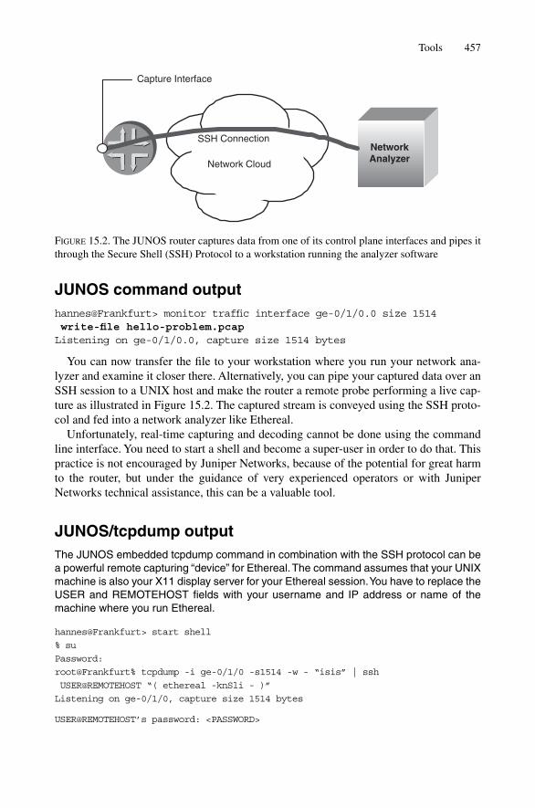
JUNOS command outputhannes@Frankfurt> monitor traffic interface ge-0/1/0.0 size 1514 write-file hello-problem.pcapListening on ge-0/1/0.0, capture size 1514 bytes
You can now transfer the file to your workstation where you run your network ana-lyzer and examine it closer there. Alternatively, you can pipe your captured data over anSSH session to a UNIX host and make the router a remote probe performing a live cap-ture as illustrated in Figure 15.2. The captured stream is conveyed using the SSH proto-col and fed into a network analyzer like Ethereal.
Unfortunately, real-time capturing and decoding cannot be done using the commandline interface. You need to start a shell and become a super-user in order to do that. Thispractice is not encouraged by Juniper Networks, because of the potential for great harmto the router, but under the guidance of very experienced operators or with JuniperNetworks technical assistance, this can be a valuable tool.
JUNOS/tcpdump outputThe JUNOS embedded tcpdump command in combination with the SSH protocol can bea powerful remote capturing “device” for Ethereal.The command assumes that your UNIXmachine is also your X11 display server for your Ethereal session.You have to replace theUSER and REMOTEHOST fields with your username and IP address or name of themachine where you run Ethereal.
hannes@Frankfurt> start shell
% su
Password:
root@Frankfurt% tcpdump -i ge-0/1/0 -s1514 -w - “isis” | ssh
USER@REMOTEHOST “( ethereal -knSli - )”
Listening on ge-0/1/0, capture size 1514 bytes
USER@REMOTEHOST’s password: <PASSWORD>
Tools 457
Network Cloud
NetworkAnalyzer
Capture Interface
SSH Connection
FIGURE 15.2. The JUNOS router captures data from one of its control plane interfaces and pipes itthrough the Secure Shell (SSH) Protocol to a workstation running the analyzer software

After 1–2 seconds you should see Ethereal starting up, as illustrated in Figure 15.3.Two windows will be opened. On the foreground capture window you can see brief per-protocol statistics. The background window is divided into three parts. The top windowis the packet browser which shows a packet per line. The middle section decodes theselected packet. In the third window there is a hex dump of the packet. A nice functionof Ethereal is that once you select a branch in the middle section, for example a TLV, thenthe corresponding hex dump digits do get highlighted.
If the screen output needs to get redirected to a remote station using the X11 protocol,you first need to give a hint where the display server is located. You need to properly set theDISPLAY environment variable for specifying the IP address of the X11 server. Changingenvironment variables depends on the UNIX shell type. The example shows a remote X11server and assumes that the shell for changing the DISPLAY variable is the Bourne AgainShell (bash) that is today the preferred shell on many UNIX-based systems.
JUNOS/tcpdump outputIf your display server is not the machine where Ethereal is running, you need to specifythe IP address of the X11 server. Replace the XSERVERHOST string with the name or IPaddress of your X11 server.
hannes@Frankfurt> start shell
% su
Password:
root@Frankfurt% tcpdump -i ge-0/1/0 -s1514 -w - “isis” | ssh USER@REMOTEHOST
“( export DISPLAY = XSERVERHOST:0; ethereal -knSli - )”
Listening on ge-0/1/0, capture size 1514 bytes
USER@REMOTEHOST’s password: <PASSWORD>
Ethereal comes in two flavours: the first one features a graphical user interface (GUI).The GUI version has been utilized in the previous examples. The second one renders theentire packet as a text-only output that may be used for users that just have terminalaccess to a UNIX station. The text version of Ethereal is called Tethereal and displaysthe full networking stack, including Layer 2 information of a given packet.
JUNOS/Ethereal outputT-Ethereal provides a very nice text-only output variant displaying the full NetworkingStack and all of its details.
hannes@Frankfurt> start shell
% su
Password:
root@Frankfurt% tcpdump -i ge-0/1/0 -s1514 -w - “isis” | ssh
USER@REMOTEHOST “( tethereal -nVli - )”
Listening on ge-0/1/0, capture size 1514 bytes
USER@REMOTEHOST’s password: <PASSWORD>
458 15. Troubleshooting
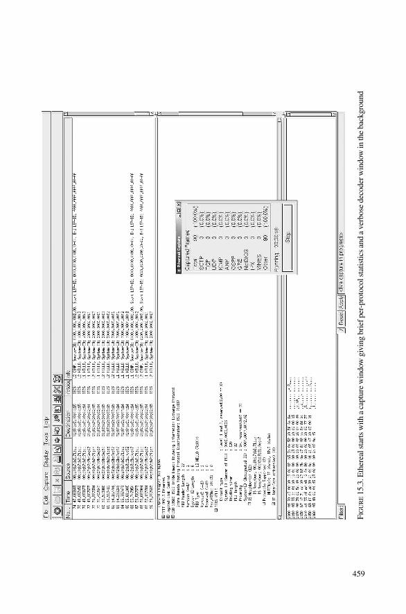
FIG
UR
E15
.3.E
ther
eal s
tart
s w
ith a
cap
ture
win
dow
giv
ing
brie
f per
-pro
toco
l sta
tistic
s an
d a
v erb
ose
deco
der w
indo
w in
the
back
grou
nd
459

Capturing on -
Frame 1 (1509 bytes on wire, 1509 bytes captured)
Arrival Time: Nov 20, 2003 11:39:56.002525000
Time delta from previous packet: 0.000000000 seconds
Time since reference or first frame: 0.000000000 seconds
Frame Number: 1
Packet Length: 1509 bytes
Capture Length: 1509 bytes
[ … ]
ISO 10589 ISIS InTRA Domain Routeing Information Exchange Protocol
Intra Domain Routing Protocol Discriminator: ISIS (0x83)
PDU Header Length : 27
Version (==1) : 1
System ID Length : 6
PDU Type : L2 HELLO (R:000)
Version2 (==1) : 1
Reserved (==0) : 0
Max.AREAs: (0==3) : 0
ISIS HELLO
Circuit type : Level 1 and 2, reserved(0x00 == 0)
System-ID {Sender of PDU} : 0000.0000.0001
Holding timer : 27
PDU length : 1492
Priority : 64, reserved(0x00 == 0)
System-ID {Designated IS} : 0000.0000.0002.02
IS Neighbor(s) (12)
IS Neighbor: 00:d0:b7:b2:71:cc
IS Neighbor: 00:02:b3:2b:0e:52
[ … ]
15.3 Case Studies
In this section you will see examples of broken IS-IS configurations. The majority ofproblems revolve around adjacency and sub-net configuration which mostly have router-local impact only. There is, however, a devastating example that can cause an entire net-work meltdown. Frequent encounters with this latter problem even caused the routervendors to provide a protection knob that should be turned on.
Most IS-IS problems are problems bringing up an adjacency. Therefore, we will dis-cuss the main six problems on the topic of adjacencies and how to quickly diagnose whatthe problem is.
15.3.1 Broken IS-IS AdjacencyRather than comparing individual configurations against another, we will start out withtwo configurations that encompass in total five mistakes and incrementally troubleshootthe two configurations.
460 15. Troubleshooting
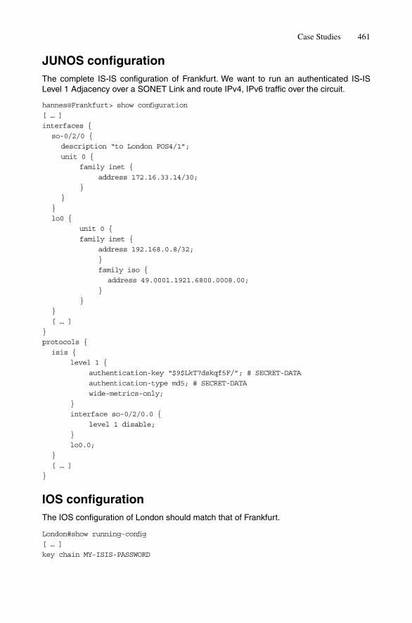
JUNOS configurationThe complete IS-IS configuration of Frankfurt. We want to run an authenticated IS-ISLevel 1 Adjacency over a SONET Link and route IPv4, IPv6 traffic over the circuit.
hannes@Frankfurt> show configuration
[ … ]
interfaces {
so-0/2/0 {
description “to London POS4/1”;
unit 0 {
family inet {
address 172.16.33.14/30;
}
}
}
lo0 {
unit 0 {
family inet {
address 192.168.0.8/32;
}
family iso {
address 49.0001.1921.6800.0008.00;
}
}
}
[ … ]
}
protocols {
isis {
level 1 {
authentication-key “$9$LkT7dskqf5F/”; # SECRET-DATA
authentication-type md5; # SECRET-DATA
wide-metrics-only;
}
interface so-0/2/0.0 {
level 1 disable;
}
lo0.0;
}
[ … ]
}
IOS configurationThe IOS configuration of London should match that of Frankfurt.
London#show running-config
[ … ]
key chain MY-ISIS-PASSWORD
Case Studies 461

key 1
key-string 0 secret789
!
interface POS4/1
description “to Frankfurt so-0/2/0”
ip address 172.16.33.17 255.255.255.252
ip router isis
encapsulation ppp
crc 16
clock source internal
pos scramble-atm
isis circuit-type level-1
!
router isis
net 49.0010.1921.6800.0012.00
authentication mode md5
authentication key-chain MY-ISIS-PASSWORD
metric-style wide
is-type level-1
passive-interface Loopback0
!
Let’s see if the two configurations are working. Nope, neither router sees the other. Whatcould be wrong?
London#sh clns neighbors
System Id Interface SNPA State Holdtime Type Protocol
hannes@Frankfurt> show isis adjacency
hannes@Frankfurt> show isis interface
IS-IS interface database:
Interface L CirID Level 1 DR Level 2 DR L1/L2 Metric
lo0.0 0 0x1 Disabled Passive 0/0
15.3.1.1 Missing PPP-OSICP Configuration
In our phased troubleshooting approach, first we’ll check the underlying physical andlogical interface:
IOS command outputOnly IPCP is up – The OSICP state is listening.
London#show interfaces pos4/1
POS4/1 is up, line protocol is up
Hardware is Packet over SONET
Description: “to Frankfurt so-0/2/0”
Internet address is 172.16.33.13/30
MTU 4470 bytes, BW 155000Kbit, DLY 100 usec, rely 255/255,
load 1/255
462 15. Troubleshooting

Encapsulation PPP, crc 16, loopback not set
Keepalive set (10sec)
Scramble enabled
LCP Open
Listen: CDPCP, OSICP
Open: IPCP
[ … ]
JUNOS command outputOn the JUNOS side we do not even attempt to open up the OSICP because the router isnot configured to do so!
hannes@Frankfurt> show interfaces so-0/2/0
Physical interface: so-0/2/0, Enabled, Physical link is Up
Interface index: 148, SNMP ifIndex: 66
Description: to London POS4/1
Link-level type: PPP, MTU: 4474, Clocking: Internal, FCS: 16,
Payload scrambler: Enabled
Device flags : Present Running
Interface flags: Point-To-Point SNMP-Traps
Link flags : Keepalives
Keepalive settings: Interval 10 seconds, Up-count 1, Down-count 3
Keepalive: Input: 291 (00:00:04 ago), Output: 296 (00:00:03 ago)
LCP state: Opened
NCP state: inet: Opened, inet6: Not-configured, iso: Not-
configured, mpls: Not-configured
CHAP state: Not-configured
[ … ]
On the IOS side, we encounter a circuit that is eager to speak OSICP, but does notreceive any OSI frame from the other side. We can also rule out physical problems at thispoint as the Line Control Protocol (LCP) and IP Control Protocol (IPCP) are both up andrunning. On the JUNOS side, the output tells us that OSI support is not even configured.Checking the configuration reveals that we forgot to set the family iso keyword atthe logical interface level (you’d be surprised how often this happens).
JUNOS configuration changeWe forgot the family iso on the SONET interface on the JUNOS side. So the PPP-OSICPdid not get started.
hannes@Frankfurt# show | compare
[edit interfaces so-0/2/0 unit 0]
+ family iso;
After adding the family iso statement at the logical interface Level, OSICP comesup, but our adjacency is still down. What else could be wrong?
Case Studies 463

15.3.1.2 Non-matching Level
Next, we check to see if there is a mismatch in our Level configuration by checking thedebug logfiles.
JUNOS configuration/debug outputThe JUNOS trace log reveals that there is a Level mismatch.
hannes@Frankfurt> show configuration protocols isis
traceoptions {
file isis-trace.log;
flag hello detail;
flag error;
}
[ … ]
*** isis-trace.log ***
Nov 21 23:53:11 Received PTP IIH, source id 1921.6800.0012 on so-0/2/0.0
Nov 21 23:53:11 intf index 69
Nov 21 23:53:11 max area 0, circuit type l1, packet length 4469
Nov 21 23:53:11 hold time 30, circuit id 1
Nov 21 23:53:11 ERROR: IIH from 1921.6800.0012 with no matching
level, interface so-0/2/0.0, circuit type 1
The Frankfurt router complains that it got a Hello from London and there is a circuitmismatch reported.
IOS debug outputIOS does not detect any Level mismatches.
London#debug isis adj-packets
IS-IS Adjacency related packets debugging is on
*Nov 22 00:49:12: ISIS-Adj: Rec serial IIH from *PPP* (POS4/1), cir type L2,
cir id 01, length 67
*Nov 22 00:49:12: ISIS-Adj: rcvd state DOWN, old state INIT, new state INIT
*Nov 22 00:49:12: ISIS-Adj: Action = GOING DOWN
Note that in the IOS debug file there is no indication for a Level mismatch. But check-ing the JUNOS configuration, we find out that somebody must have set the Level 1 dis-able knob on the interface, which prevents a common Level to be found between therouters during the adjacency establishment process.
JUNOS configuration diffClearing the Level 1 disable flag makes the circuit a L1L2 circuit so that both peershave a common circuit type.
hannes@Frankfurt# show | compare
[edit protocols isis interface so-0/2/0.0]
- level 1 disable;
464 15. Troubleshooting
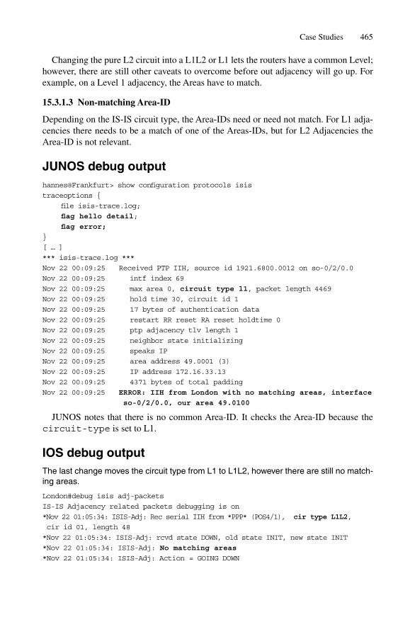
Changing the pure L2 circuit into a L1L2 or L1 lets the routers have a common Level;however, there are still other caveats to overcome before out adjacency will go up. Forexample, on a Level 1 adjacency, the Areas have to match.
15.3.1.3 Non-matching Area-ID
Depending on the IS-IS circuit type, the Area-IDs need or need not match. For L1 adja-cencies there needs to be a match of one of the Areas-IDs, but for L2 Adjacencies theArea-ID is not relevant.
JUNOS debug outputhannes@Frankfurt> show configuration protocols isis
traceoptions {
file isis-trace.log;
flag hello detail;
flag error;
}
[ … ]
*** isis-trace.log ***
Nov 22 00:09:25 Received PTP IIH, source id 1921.6800.0012 on so-0/2/0.0
Nov 22 00:09:25 intf index 69
Nov 22 00:09:25 max area 0, circuit type l1, packet length 4469
Nov 22 00:09:25 hold time 30, circuit id 1
Nov 22 00:09:25 17 bytes of authentication data
Nov 22 00:09:25 restart RR reset RA reset holdtime 0
Nov 22 00:09:25 ptp adjacency tlv length 1
Nov 22 00:09:25 neighbor state initializing
Nov 22 00:09:25 speaks IP
Nov 22 00:09:25 area address 49.0001 (3)
Nov 22 00:09:25 IP address 172.16.33.13
Nov 22 00:09:25 4371 bytes of total padding
Nov 22 00:09:25 ERROR: IIH from London with no matching areas, interface
so-0/2/0.0, our area 49.0100
JUNOS notes that there is no common Area-ID. It checks the Area-ID because thecircuit-type is set to L1.
IOS debug outputThe last change moves the circuit type from L1 to L1L2, however there are still no match-ing areas.
London#debug isis adj-packets
IS-IS Adjacency related packets debugging is on
*Nov 22 01:05:34: ISIS-Adj: Rec serial IIH from *PPP* (POS4/1), cir type L1L2,
cir id 01, length 48
*Nov 22 01:05:34: ISIS-Adj: rcvd state DOWN, old state INIT, new state INIT
*Nov 22 01:05:34: ISIS-Adj: No matching areas
*Nov 22 01:05:34: ISIS-Adj: Action = GOING DOWN
Case Studies 465
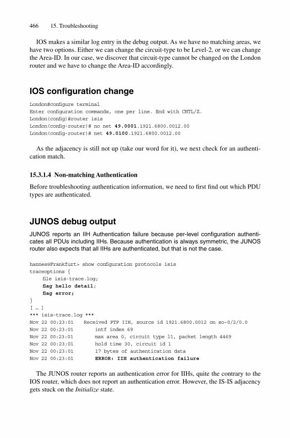
IOS makes a similar log entry in the debug output. As we have no matching areas, wehave two options. Either we can change the circuit-type to be Level-2, or we can changethe Area-ID. In our case, we discover that circuit-type cannot be changed on the Londonrouter and we have to change the Area-ID accordingly.
IOS configuration changeLondon#configure terminal
Enter configuration commands, one per line. End with CNTL/Z.
London(config)#router isis
London(config-router)# no net 49.0001.1921.6800.0012.00
London(config-router)# net 49.0100.1921.6800.0012.00
As the adjacency is still not up (take our word for it), we next check for an authenti-cation match.
15.3.1.4 Non-matching Authentication
Before troubleshooting authentication information, we need to first find out which PDUtypes are authenticated.
JUNOS debug outputJUNOS reports an IIH Authentication failure because per-level configuration authenti-cates all PDUs including IIHs. Because authentication is always symmetric, the JUNOSrouter also expects that all IIHs are authenticated, but that is not the case.
hannes@Frankfurt> show configuration protocols isis
traceoptions {
file isis-trace.log;
flag hello detail;
flag error;
}
[ … ]
*** isis-trace.log ***
Nov 22 00:23:01 Received PTP IIH, source id 1921.6800.0012 on so-0/2/0.0
Nov 22 00:23:01 intf index 69
Nov 22 00:23:01 max area 0, circuit type l1, packet length 4469
Nov 22 00:23:01 hold time 30, circuit id 1
Nov 22 00:23:01 17 bytes of authentication data
Nov 22 00:23:01 ERROR: IIH authentication failure
The JUNOS router reports an authentication error for IIHs, quite the contrary to theIOS router, which does not report an authentication error. However, the IS-IS adjacencygets stuck on the Initialize state.
466 15. Troubleshooting

IOS debug outputOn the IOS side, no authentication error is logged because IOS does not expect its Hellosto be authenticated.
London#debug isis authentication information
IS-IS authentication information debugging is on
London#debug isis adj-packets
IS-IS Adjacency related packets debugging is on
*Nov 22 01:19:34: ISIS-Adj: Rec serial IIH from *PPP* (POS4/1),
cir type L1L2, cir id 01, length 67
*Nov 22 01:19:34: ISIS-Adj: rcvd state DOWN, old state INIT, new state INIT
*Nov 22 01:19:34: ISIS-Adj: Action = GOING UP, new type = L1
Although IOS has enabled MD5 authentication, it authenticates only LSPs and SNPsand not IIHs. But JUNOS does authenticate all PDU types and also expects authentica-tion from others, which breaks the adjacency in this case. There are two strategies to overcome this.
IOS configuration changeLondon#conf t
Enter configuration commands, one per line. End with CNTL/Z.
London(config)#int pos4/1
London(config-if)# isis authentication key-chain MY-ISIS-PASSWORD
London(config-if)# isis authentication mode md5
The first is to configure an additional IIH authentication on the interface.
JUNOS configuration changehannes@Frankfurt# show | compare
[edit protocols isis level 1]
+ no-hello-authentication;
Most network administrators are too lazy to maintain an additional IS-IS configurationstatement, and it is decided decide to suppress the authentication of IIH PDUs throughuse of the no-hello-authentication on the JUNOS router.
15.3.1.5 Non-matching IP Sub-net
As our adjacency is still not up, we check the IP sub-net information using show com-mands. Additionally we keep an eye on the debug outputs.
JUNOS debug outputhannes@Frankfurt> show configuration protocols isis
traceoptions {
Case Studies 467
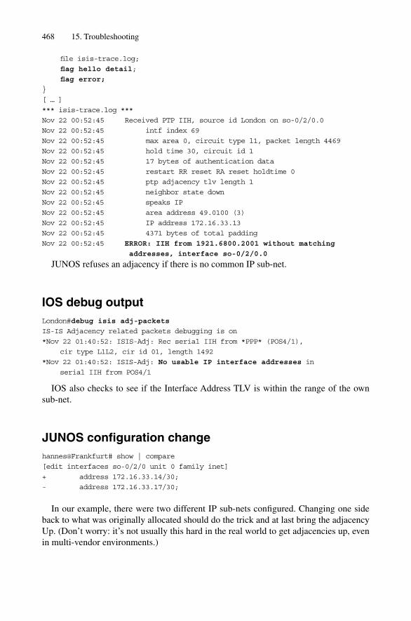
file isis-trace.log;
flag hello detail;
flag error;
}
[ … ]
*** isis-trace.log ***
Nov 22 00:52:45 Received PTP IIH, source id London on so-0/2/0.0
Nov 22 00:52:45 intf index 69
Nov 22 00:52:45 max area 0, circuit type l1, packet length 4469
Nov 22 00:52:45 hold time 30, circuit id 1
Nov 22 00:52:45 17 bytes of authentication data
Nov 22 00:52:45 restart RR reset RA reset holdtime 0
Nov 22 00:52:45 ptp adjacency tlv length 1
Nov 22 00:52:45 neighbor state down
Nov 22 00:52:45 speaks IP
Nov 22 00:52:45 area address 49.0100 (3)
Nov 22 00:52:45 IP address 172.16.33.13
Nov 22 00:52:45 4371 bytes of total padding
Nov 22 00:52:45 ERROR: IIH from 1921.6800.2001 without matching
addresses, interface so-0/2/0.0
JUNOS refuses an adjacency if there is no common IP sub-net.
IOS debug outputLondon#debug isis adj-packets
IS-IS Adjacency related packets debugging is on
*Nov 22 01:40:52: ISIS-Adj: Rec serial IIH from *PPP* (POS4/1),
cir type L1L2, cir id 01, length 1492
*Nov 22 01:40:52: ISIS-Adj: No usable IP interface addresses in
serial IIH from POS4/1
IOS also checks to see if the Interface Address TLV is within the range of the own sub-net.
JUNOS configuration changehannes@Frankfurt# show | compare
[edit interfaces so-0/2/0 unit 0 family inet]
+ address 172.16.33.14/30;
- address 172.16.33.17/30;
In our example, there were two different IP sub-nets configured. Changing one sideback to what was originally allocated should do the trick and at last bring the adjacencyUp. (Don’t worry: it’s not usually this hard in the real world to get adjacencies up, evenin multi-vendor environments.)
468 15. Troubleshooting

IOS debug output*Nov 22 01:54:50: ISIS-Adj: Rec serial IIH from *PPP* (POS4/1),cir type
L1L2, cir id 01,length 1492
*Nov 22 01:54:50: ISIS-Adj: rcvd state INIT, old state DOWN, new state INIT
*Nov 22 01:54:50: ISIS-Adj: Action = GOING UP, new type = L1
*Nov 22 01:54:50: ISIS-Adj: New serial adjacency
*Nov 22 01:54:50: ISIS-Adj: Sending serial IIH on POS4/1, length 4469
*Nov 22 01:54:50: ISIS-Adj: Rec serial IIH from *PPP* (POS4/1), cir type
L1L2, cir id 01, length 58
*Nov 22 01:54:50: ISIS-Adj: rcvd state UP, old state INIT, new state UP
*Nov 22 01:54:50: ISIS-Adj: Action = GOING UP, new type = L1
*Nov 22 01:54:50: ISIS-Adj: L1 adj count 1
The debug output shows the state transition from the Down to the Up state. Once weare there, our routers can talk to their neighbours and exchange LSPs. Sometimes routersexchange a bit too many LSPs, which is undesirable, too – there is a closer description ofthis problem in the following case study.
15.3.2 Injecting Full Internet Routes into IS-ISIt is the nightmare of every network operation engineer: getting paged in the middle ofthe night and all routers are unreachable. The iBGP mesh is collapsing and the networkis literally falling to pieces. Particularly on JUNOS routers, there was a dangerous trapthat many service providers ran into. In 2002, the Juniper Technical Assistance Center(JTAC) noticed several incidents of the type we describe here: through human error, arouter attempts to inject the full set of Internet routes into IS-IS Level 2. The generatedflooding and processing load eventually melts down the entire network.
During a network-wide failure, it is hard at first to determine where to look initially fortraces and clues. A good place is the central syslog server. Often a few syslog messagesthat are logged just before the network go haywire and these provide a good startingpoint.
Syslog server logfileThe Munich router is logging every second that its IS-IS database is overloaded.
[ … ]
Nov 21 18:22:22 Munich rpd[2235]: RPD_ISIS_OVERLOAD: IS-IS database overload
Nov 21 18:22:23 Munich rpd[2235]: RPD_ISIS_OVERLOAD: IS-IS database overload
Nov 21 18:22:24 Munich rpd[2235]: RPD_ISIS_OVERLOAD: IS-IS database overload
Nov 21 18:22:25 Munich rpd[2235]: RPD_ISIS_OVERLOAD: IS-IS database overload
Nov 21 18:22:26 Munich rpd[2235]: RPD_ISIS_OVERLOAD: IS-IS database overload
[ … ]
Case Studies 469
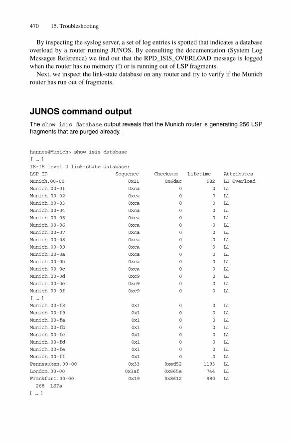
By inspecting the syslog server, a set of log entries is spotted that indicates a databaseoverload by a router running JUNOS. By consulting the documentation (System LogMessages Reference) we find out that the RPD_ISIS_OVERLOAD message is loggedwhen the router has no memory (!) or is running out of LSP fragments.
Next, we inspect the link-state database on any router and try to verify if the Munichrouter has run out of fragments.
JUNOS command outputThe show isis database output reveals that the Munich router is generating 256 LSPfragments that are purged already.
hannes@Munich> show isis database
[ … ]
IS-IS level 2 link-state database:
LSP ID Sequence Checksum Lifetime Attributes
Munich.00-00 0x11 0x6dac 982 L1 Overload
Munich.00-01 0xca 0 0 L1
Munich.00-02 0xca 0 0 L1
Munich.00-03 0xca 0 0 L1
Munich.00-04 0xca 0 0 L1
Munich.00-05 0xca 0 0 L1
Munich.00-06 0xca 0 0 L1
Munich.00-07 0xca 0 0 L1
Munich.00-08 0xca 0 0 L1
Munich.00-09 0xca 0 0 L1
Munich.00-0a 0xca 0 0 L1
Munich.00-0b 0xca 0 0 L1
Munich.00-0c 0xca 0 0 L1
Munich.00-0d 0xc9 0 0 L1
Munich.00-0e 0xc9 0 0 L1
Munich.00-0f 0xc9 0 0 L1
[ … ]
Munich.00-f8 0x1 0 0 L1
Munich.00-f9 0x1 0 0 L1
Munich.00-fa 0x1 0 0 L1
Munich.00-fb 0x1 0 0 L1
Munich.00-fc 0x1 0 0 L1
Munich.00-fd 0x1 0 0 L1
Munich.00-fe 0x1 0 0 L1
Munich.00-ff 0x1 0 0 L1
Pennsauken.00-00 0x33 0xed52 1193 L1
London.00-00 0x3af 0x865e 744 L1
Frankfurt.00-00 0x19 0x8612 980 L1
268 LSPs
[ … ]
470 15. Troubleshooting

The output looks odd – the Munich router is generating in total 256 fragments, and therouter is overloaded. Why? Inspecting the non-zero fragments shows another interestingtrace:
JUNOS command outputAll the Munich non-zero LSP fragments have the garbage collection timer set.
hannes@Frankfurt> show isis database Munich.00-01 extensive
IS-IS level 2 link-state database:
[ … ]
Munich.00-01 Sequence: 0xca, Checksum: 0, Lifetime: 0secs
Header: LSP ID: Munich.00-01, Length: 40 bytes
Allocated length: 284 bytes, Router ID: 0.0.0.0
Remaining lifetime: 0secs, Level: 1,Interface: 64
Estimated free bytes: 209, Actual free bytes: 244
Garbage collection timer expires in: 1134secs
[ … ]
The LSP fragments do not contain any data anymore. All of them are still in the database for their maximum LSP lifetime to avoid re-learning them in case the networkgets partitioned. For our further troubleshooting, this means that somebody has purged the Munich LSP fragments. In IS-IS the only router that purges LSPs is the orig-inating router. So we next inspect the Munich router and check out its router configura-tion file.
JUNOS configurationThe IS-IS configuration looks alright, but there is also an export policy configured whichshould be further inspected.
hannes@Munich> show configuration
[ … ]
protocols {
isis {
export static-to-isis;
level 2 {
wide-metric-only;
}
interfaces {
[ … ]
lo0.0;
}
[ … ]
}
}
Case Studies 471

The IS-IS configuration looks alright – all interfaces are referenced. At the top there isa pointer to an export policy which we will examine closer.
JUNOS configurationOn first sight the static-to-isis policy looks good, however once you check the inden-tation of the terms and accept statements you will find out that the policy does not do whatthe network operator wanted it to do.
hannes@Munich> show configuration policy-options
[ … ]
policy-statement static-to-isis {
term reject_management {
from {
route-filter 10.0.0.0/8 orlonger;
}
then reject;
}
term static {
from protocol static;
}
then accept;
}
At first sight this policy looks good. However, once we start to compare the indenta-tion of the then part we realize that the term static does not have a valid then state-ment. Due to a misconfiguration, it got inserted at the wrong level in the policy. What thestandalone then accept term does is accept every unicast route in the inet.0 routingtables and mark it for export into the IS-IS link-state database. Because there is no fromstatement at the same indentation level as the final then accept statement, we havean unconditional export of the entire Internet routing table into IS-IS. (The final “then”logic is executed when no terms match the routes. The logic is here “Is the route 10/8 orlonger?” No, that’s a private address. “Is the route static?” No, it’s an Internet route.“Okay, then unconditionally accept the route into IS-IS.”)
The distributed storage space that each node may allocate is 1492(–27) * 256 �375 Kbytes. How many IPv4 prefixes do fit in those 375 Kbytes? Figure 12.11 in Chapter12 “IP Reachability Information” illustrates the structure and storage requirements of theExtended IP Reachability TLV #135. Worst case, the TLV consumes 9 bytes and bestcase 5 bytes due to variable prefix length packing. For the average Internet route we canassume a prefix length between /16 and /24 and safely assume a total storage requirementof 8 bytes per prefix. In a single TLV, on average, 31 TLVs fit, which requires 31 * 8 + 2(TLV Overhead) � 250 bytes to store. An LSP fragment is at maximum 1492 bytes insize. For TLV information there is 1492 – Header size (�27) � 1465 space. That meansin total we can store 31 * 5 + 26 � 181 routes per fragment. Inside 256 fragments we canstore around 46 K routes, which is too little to hold the entire Internet routing table. Assoon as the routers hit that limit, it pulls the “emergency brake” and sets the overload bit.
472 15. Troubleshooting

Finally, it cleans up the mess by purging the previously generated LSPs off the distrib-uted link-state database. And that’s what the router was showing us.
In order to fix the problem, the then accept statement is moved into the termstatic.
JUNOS configurationhannes@Munich> show configuration
[ … ]
policy-statement static-to-isis {
term reject_management {
from {
route-filter 10.0.0.0/8 orlonger;
}
then reject;
}
term static {
from protocol static;
then accept;
}
}
After committing the change, you will still see all those stale fragments in the data-base. They will be kept in the database until the garbage collection timer times out. Usingdefault values, after a period of 20 minutes they are removed automatically.
JUNOS command outputAfter the router has changed, the broken routing policy the Overload Bit is automaticallycleared.
hannes@Munich> show isis database
IS-IS level 2 link-state database:
LSP ID Sequence Checksum Lifetime Attributes
Munich.00-00 0x1c2 0x2d3b 1192 L1 L2
Pennsauken.00-00 0xc77 0xec5e 711 L1 L2
Frankfurt.00-00 0x198 0xdd86 933 L1 L2
14 LSPs
[ … ]
The database looks normal again, and the Overload Bit has automatically beencleared.
Because that problem was encountered many times in the field, Juniper Networksfinally introduced a prefix-export limiter that optionally controls the export behaviourand suspends route export if a predefined threshold is reached.
Case Studies 473

474 15. Troubleshooting
JUNOS configurationThe prefix-export-limit knob protects the rest of the network from a maliciouspolicy by applying a threshold filter for exported routed.
hannes@Munich> show configuration
[ … ]
protocols {
isis {
export static-to-isis;
level 2 {
wide-metrics-only;
prefix-export-limit 2500;
}
}
}
The amount of prefixes heavily depends on the size of your network. Good designadvice is to set it to double the total number of IS-IS Level 1 and Level-2 routers in yournetwork – The minimum number of routes should be 1000 and the maximum number ofroutes about 10,000. Then you have some growth for even larger numbers of routes thatneed to get leaked from Level 1 to Level 2.
15.4 Summary
Most IS-IS problems can be resolved quickly if you stick to a troubleshooting plan andcheck from Layer-1 of the OSI Reference Model right up to the Application Layer. In IS-IS, the Application Layer represents the link-state database that holds the network’slink state PDUs. The network engineer needs to develop an understanding of what func-tions each layer is performing and what tools he has available to gather information.After information gathering, the collected data needs to be analyzed and interpreted,which requires knowledge of the show commands and debug outputs. For detecting mis-configuration on a router, the network engineer needs to understand where the IS-IS rele-vant data in the configuration are stored.
The majority of IS-IS problems are related to adjacency formation. The network engineerneeds to get familiar with all sorts of debug output for IOS and JUNOS. Just looking atthe IS-IS specific configuration is often not enough to resolve a problem. We havedemonstrated in the Internet route export case study that understanding of route exportand policy processing is paramount for resolving complex problems.

16
Network Design
For a long time, link-state protocols were believed not to scale. However, today there areoperational networks with more than 1200 routers in a single level. Still, networks that runlink-state protocols need to be carefully designed and a lot of factors need to be consideredto get to such a scale. By ignoring certain reasonable constraints, you can easily break anetwork in certain scenarios. In this chapter you will learn about the critical IS-IS networkdesign factors, all forms of router stress, including flooding stress, SPF stress and forward-ing state change stress, as well as what things to consider to build robust, fast-convergingnetworks.
16.1 Topology and Reachability Information
In service provider networks there are always at least two protocols in use. The first is anIGP (which could be OSPF or IS-IS), and the other is BGP. One of the first questionsasked by networking novices is why do we need both? It turns out that all IGPs (IS-IS,OSPF, EIGRP) lack one fundamental thing, which is flow-control. For IGPs, there is noway to tell an adjacent router that their updates have overwhelmed the receiver and thesender should throttle down. The only way to deal with the situation is to throw away theupdates and wait for re-transmission. However, that is still a dangerous game, as it mayoffload stress at the expense of the sending router, which needs to queue retransmissionsand therefore consumes CPU and memory. Careful protocol heuristics need to be imple-mented to make sure that both the sending and receiving router do not take themselvesout of service. Dave Katz, a software engineer with Juniper Networks, who can beblamed for writing the majority of IGP implementations on the Internet (his own self-definition) puts the complexity around finding the right heuristics in a single quote:
Link State Protocols are hard! (Dave Katz)
What network engineers at service providers have been doing is to apply a divide andconquer strategy and separating topology from reachability information. Topology infor-mation contains the skeleton of the network – it is a graph that describes how the routing-nodes are connected to each other. It does not contain any information about customernetworks and server networks, or so on. Ideally, it does not even contain informationabout the directly connected sub-nets. Figure 16.1 shows that the only information that therouters advertise is their loopback IP address, which is necessary to bring up an iBGP full-mesh distribution network which handles bulk transport of the routing information.
475
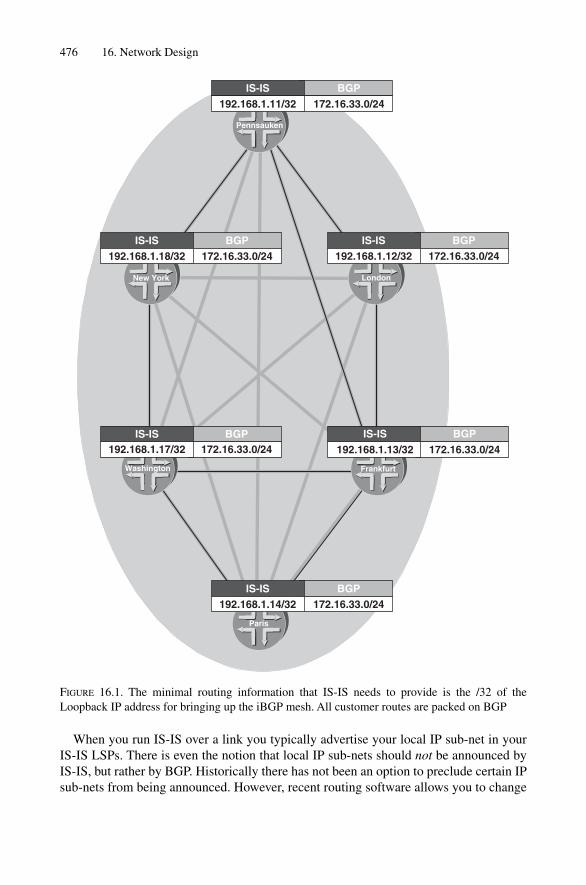
476 16. Network Design
When you run IS-IS over a link you typically advertise your local IP sub-net in yourIS-IS LSPs. There is even the notion that local IP sub-nets should not be announced byIS-IS, but rather by BGP. Historically there has not been an option to preclude certain IPsub-nets from being announced. However, recent routing software allows you to change
BGPBGP
BGP
BGPBGP
BGP
Washington
IS-ISIS-IS
IS-IS
IS-ISIS-IS
IS-IS
192.168.1.11/32 172.16.33.0/24
Pennsauken
192.168.1.18/32 172.16.33.0/24
New York
192.168.1.12/32 172.16.33.0/24
London
192.168.1.17/32 172.16.33.0/24 192.168.1.13/32 172.16.33.0/24
Frankfurt
192.168.1.14/32 172.16.33.0/24
Paris
FIGURE 16.1. The minimal routing information that IS-IS needs to provide is the /32 of theLoopback IP address for bringing up the iBGP mesh. All customer routes are packed on BGP

that behaviour. In IOS, there is a single knob that changes the advertising behaviour ofdirectly connects sub-nets. Once you configure the passive-only knob, the routingsoftware walks down the list of configured interfaces and looks for interfaces that aremarked as passive. Recall that passive means that you include that interface’ssub-net in your routing update, but you do not try to establish a neighbour relationship oran adjacency over that interface. The loopback interface is by default passive and soif you configure the passive-only option, only the loopback IP address of the routeris advertised in its LSP.
IOS configurationIn IOS controlling whether directly connected route get advertised is provided using thepassive-only knob.
New-York# show running-config
[ … ]
router isis
advertise passive-only
!
[ … ]
In JUNOS there is no specific knob to control advertising behaviour. In JUNOS youwrite a policy for achieving that task. Later you call that policy as export policy in theprotocols isis {} branch.
JUNOS configurationIn JUNOS you need to write an explicit policy that rejects all routes beside sub-nets on thelo0.0 interface.
hannes@Frankfurt# show
[ … ]
protocols {
isis {
export lo0-only;
[ … ]
}
}
policy-options {
policy-statement lo0-only {
term lo0 {
from interface lo0.0;
then accept;
}
term final {
then reject;
}
[ … ]
Topology and Reachability Information 477

The nice thing about the JUNOS policy is that you may explicitly control the level tosuppress direct routes by introduction of a to {} statement. The following exampleshows how to restrict to the loopback0 interface related routes inside Level 2 LSPs only.
policy-options {
policy-statement lo0-only {
term lo0 {
from interface lo0.0;
to {
protocol isis;
level 2;
}
then accept;
}
term final {
then reject }
}
}
[ … ]
}
BGP has perfected flow-control capabilities because it runs on top of the TransmissionControl Protocol (TCP). Flow control at the TCP level is built into the protocol: as soonas a receiver cannot keep up processing inbound routing updates, it can easily slow downtransmission of acknowledgements or even drop the inbound update and indirectly indi-cate that the sender should back off and send information at a lower speed. OriginallyBGP was intended to process a certain maximum of routes. Yakov Rekhter, an Internetarchitect with Juniper Networks relates:
Kirk Lougheed (Cisco Systems) and myself’s goal was to build a routing protocol ableto convey 1000 routes and not fall into pieces – If you consider the total routes beingtoday in the Internet we pushed the envelope a bit (Yakov Rekhter)
Based on BGP’s superb scaling capabilities, the idea here is to “borrow” the existingBGP distribution mesh being used for transport of Internet routes for internal routes as well.
The conclusion as to why you always need two protocols is therefore: IS-IS scales too poorly for conveying a bulk amount of routes, however, it can quickly discover a topology and provide routing connectivity between router loopback IP addresses. BGPheavily depends on these IGP-supplied routes to bring up the iBGP. Second, BGP isreally in the dark when it comes to ascertaining the distance between a pair of routers.Internal BGP sessions are not “targeted” and therefore need an IGP to resolve routes andto give BGP speakers directions.
In order to come up with a design recommendation, let’s first evaluate the forms ofstress that routers are exposed to and develop a set of critical design factors based onthose insights. From there we will set up some rules to follow when designing an IS-ISnetwork.
478 16. Network Design

16.2 Router Stress
Generally routing software can exhaust resources in three possible areas:
1. Bandwidth2. CPU3. Memory
The next three sections investigate IS-IS implementations to see if they suffer from anylimitations in those three areas. The first area is bandwidth – in IS-IS, the main band-width consumer is related to the flooding of LSPs.
16.2.1 FloodingUnlike link-local packets like Hellos (IIH) or Synchronization packets (SNP), transmit-ting link-state PDUs (LSPs) has a network-wide bandwidth usage impact. Once a routerfloods LSPs, it is using bandwidth equal to the number of links in a given topology timesthe size of the LSP. Worst case, it can be that network-wide transmission of an LSPcomes at a cost of using the number of all links times the size of a LSP squared. The biggap between the best and the worst case (recall the best case is linear behaviour and theworst case is N^2 behaviour) is solely explainable by the way the topology is meshed.Consider Figure 16.2, where in a strict ring topology of six routers there is no duplicate
Router Stress 479
Paris
Ring Topology Full-mesh Topology
Pennsauken
New York
Washington Frankfurt
London
Pennsauken
New York
Washington
Paris
Frankfurt
London
FIGURE 16.2. In a dense-meshed environment there are lots of duplicate LSPs to process

transmission of an LSP. As soon as a link breaks, the LSP travels round until every nodegets a copy. Note that for greater visibility the propagation of only one LSP is shown. Ofcourse, in real networks both ends of the link that breaks would originate a new LSP. Assoon as you add links to the topology, the more redundant the transmission of LSPs gets.In the ring-topology each router sees the LSP one time.
The worst case is a full-mesh of all routers, where a single router failure triggers(N – 1) LSPs being flooded over (N – 2) links (� O(N 2)) through the network. The bigproblem in a dense- or full-mesh environment is that nodes that already got a copy ofLSPs receive many redundant duplicates with the same information.
An additional source of flooding stress comes from turning on the TE extensions.Once you turn on features like Traffic Engineering, DiffServ Traffic Engineering or AutoBandwidth, then the TEDs throughout the network topology need to be updated throughthe use of the IS-IS flooding sub-system. That means that every router in the networksees (and needs to see) accurate TE information. However, if the TE implementation permits changes to flooding timers, then let having very conservative timers guide yourdesign. TE extensions are a major source of LSP updates and there should be an effort toreduce these to the minimum possible.
It is recommended that you consider the topology to evaluate the stress resulting fromreceipt of duplicate LSPs. Densely meshed environments scale poorly in flooding environ-ments. Try to avoid full-mesh or near-full mesh topologies. Sometimes a lot of extraredundancy does not turn into more resiliency.
16.2.2 SPF StressLink-state routing protocols were once believed to be CPU intense algorithms thatexhausted an embedded system’s sparse resources. Because of that belief, both link-stateIGPs (OSPF, IS-IS) have provisions to split the size of the link-state domains to smallerunits. In OSPF multiple areas, and in IS-IS two levels, are an attempt to spare the controlplane CPU when doing the SPF run.
A lot has changed in the last decade. CPUs became (in line with Moore’s Law) faster bya factor of 8000; Trunk bandwidth grew from T1 speeds to OC-192c/STM-64. The onlything that has not changed at all is the paranoid thinking that SPF may exhaust the CPUresources of a router. The fact is, the demand that SPF puts on router resources has beenoutpaced by the processing power of modern CPUs. Table 16.1 shows how SPF executionfares on modern route processors like the Cisco Systems GRP or a Juniper Networks RE3.0. The CPU requirements of an SPF operation are well understood and well documentedby computer scientists. The fundamental relationship is O(N * log(N )), which describes acurve where the CPU requirements grow a little more than linearly, with N being the num-ber of total routers in the network. In practice it is a little more than just log N due to the 2-way check that is needed to verify that a node is connected on both ends and not a dead end.
The results from the simulation in Table 16.1 are impressive. It means that processinga grid of 2000 routers, which are in total connected by 5000 links, has a typical execu-tion runtime of only 100–245 milliseconds. If you consider this table then it is obviousthat raw SPF execution time is not a problem for large IS-IS networks. So what is it then?
480 16. Network Design

Why are we all so scared of routers running excessive number of SPF runs back to back?What is it besides the SPF calculation itself that scares network operators so much?
16.2.3 Forwarding State Change StressThe purpose of the SPF calculation is to find out the shortest path to every edge of thenetwork. However, just the insight that there are better paths available is not enough.
There are no good things, unless you do them! (Erich Kästner)
The router has to pass on the new proximity results to a subsystem called the resolver,which is used to map third party next-hops to forwarding next-hops. Consider Figure16.3, if the link between Washington and New York breaks, the SPF calculation will befinished in a matter of microseconds. Each IS-IS speaker is also a BGP speaker and car-ries several thousand active BGP routes. If the IS-IS topology changes, then the BGProutes that depend on IS-IS need to get changed as well. The resolver needs now to back-track through all the BGP routes and verify that the BGP next-hop is affected by a changein the core topology. As you can imagine, walking down a table of several hundreds ofthousands of BGP route-entries is a resource intensive task. In our example, there aretons of forwarding state changes to do: all Washington and New York routes need to bechanged in a very short time.
After the BGP dependencies have been worked out, this may generate changes in theBGP topology as well: recall that the IGP distance is part of the BGP route selectionprocess. But that is only half of the story, as those things still occur on the control plane.
Router Stress 481
TABLE 16.1. Modern route processors can calculate topologies forthousands of nodes and links sub second.
SPF runtime (ms)
Juniper Networks Cisco Systems Routers Links Routing Engine 3.0 GRP 12000
100 250 1,92 4,80200 500 4,97 12,42400 1000 12,49 31,22600 1500 21,18 52,94800 2000 30,67 76,671000 2500 40,78 101,941500 3750 68,11 170,272000 5000 97,68 244,212500 6250 128,98 322,453000 7500 161,69 404,224000 10000 230,53 576,335000 12500 303,09 757,726000 15000 378,67 946,677000 17500 456,82 1142,048000 20000 537,19 1342,989000 22500 619,55 1548,8610000 25000 703,67 1759,18

The forwarding state change of tens of thousands of routes may stress several sub-systemsof an Internet core router. It turns out that changing a forwarding state is one of the mostexpensive operations in a router. Meanwhile, both Juniper and Cisco have found a way topass on third party next-hop information to the line-cards and retain the dependency ofBGP routes to IS-IS speakers to forwarding interfaces. More on passing on third party next-hop information, and why it is not always a good idea to attempt to fully resolve a route toits forwarding next-hop, can be found in Chapter 10, “SPF and Route Calculation”.
482 16. Network Design
Wash D.C.
Metric 4
Metric 2
Metric 4 Metric 2
Metric 1Metric 1
Metric 4 Metric 4
Pennsauken
Frankfurt
London
Washington
New York
Paris
BGP
40 K activeroutes
BGP
25 K activeroutes
BGP
30 K activeroutes
BGP
15 K activeroutes
BGP20 K active
routes
BGP
10 K activeroutes
FIGURE 16.3. The resolver needs to track and map BGP next-hops to the shortest path resultingfrom the SPF calculation

16.2.4 CPU and Memory UsageThe two main things that utilize the CPU most in an IS-IS router are the SPF calculationand the resolver. SPF calculation puts a short burden on the system but even in largetopologies that burden does not last more than 200 ms using modern route processors. Asdiscussed in the previous section, the far bigger CPU hog is the resolver, which maps BGProutes to forwarding next-hops. SPF execution runtime is ultimately a non-issue; however,the burden that the resolver can put on the system needs to be carefully examined.
In the 1990s, during the explosive growth of the Internet, routers were constantly shortof memory. Since then network service providers are cautious about the memory usage of their routing protocols. There is almost no IS-IS-related documentation regardingmemory consumption. The majority of IS-IS implementations use memory in three areas:
1. Link-state database2. SPF result table3. Storing neighbour information
The link-state database size is the easiest to predict. It contains mostly raw data thatwas extracted from the TLVs in an IS-IS PDU. There are also overhead and index struc-tures so the IS-IS software can quickly traverse the database when it is looking for a cer-tain LSP. As a rough guideline, one can state that the size of the link-state database isabout double the size that individual LSPs consume on the wire. For example, if the net-work knows about 100 LSPs with an average length of 400 bytes each, then the size tostore this information in the router software is 100 * 400 * 2 �80 KB.
The size of the SPF result table depends largely on how many IP prefixes are knownto IS-IS inside the network. A good estimation here is that each prefix consumes about70 bytes. For example, if you have 1600 IS-IS prefixes in your network, then the mem-ory consumption on the control plane is 112 KB.
The neighbouring table is the most complex one to calculate as all the flooding stateand retransmission list needs to be kept on a per adjacency basis. That structure is alsodependent on the size of the link-state database, because all the flooding states are tied toboth the LSP and the adjacency. There is a lot of clever pointer work involved here, andthe overhead to do efficient flooding is enormous. A good approximate figure is that thistable is about 50 times the average LSP size multiplied by the number of active adjacen-cies. For example, if the average LSP is about 400 bytes and the number of adjacenciesis eight, then the memory consumption is 400 * 50 * 8 �160 K.
If you sum the three memory areas up, then the result for a large network is unlikely to exceed 4–5 MB in total. In IS-IS, the memory consumption is minimal given that there are mainly route processors with 256 MB–2 GB memory deployed in the field.Interestingly, there are large overhead structures in the LSP databases to increase LSPlookup speed and to keep flooding state even for large numbers of adjacencies. This is justmore evidence that memory consumption for IS-IS networks with big core routers is anon-issue.
Router Stress 483
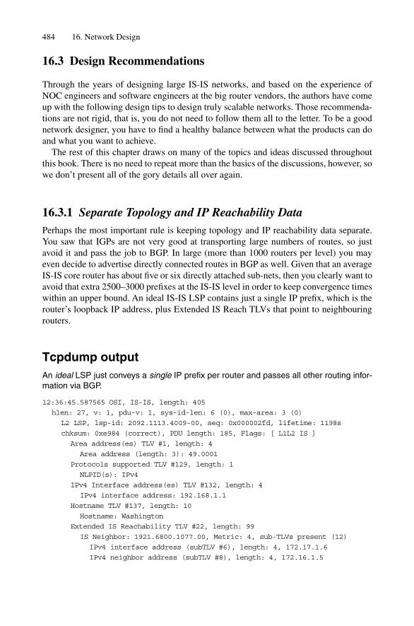
16.3 Design Recommendations
Through the years of designing large IS-IS networks, and based on the experience ofNOC engineers and software engineers at the big router vendors, the authors have comeup with the following design tips to design truly scalable networks. Those recommenda-tions are not rigid, that is, you do not need to follow them all to the letter. To be a goodnetwork designer, you have to find a healthy balance between what the products can doand what you want to achieve.
The rest of this chapter draws on many of the topics and ideas discussed throughoutthis book. There is no need to repeat more than the basics of the discussions, however, sowe don’t present all of the gory details all over again.
16.3.1 Separate Topology and IP Reachability DataPerhaps the most important rule is keeping topology and IP reachability data separate.You saw that IGPs are not very good at transporting large numbers of routes, so justavoid it and pass the job to BGP. In large (more than 1000 routers per level) you mayeven decide to advertise directly connected routes in BGP as well. Given that an averageIS-IS core router has about five or six directly attached sub-nets, then you clearly want toavoid that extra 2500–3000 prefixes at the IS-IS level in order to keep convergence timeswithin an upper bound. An ideal IS-IS LSP contains just a single IP prefix, which is therouter’s loopback IP address, plus Extended IS Reach TLVs that point to neighbouringrouters.
Tcpdump outputAn ideal LSP just conveys a single IP prefix per router and passes all other routing infor-mation via BGP.
12:36:45.587565 OSI, IS-IS, length: 405
hlen: 27, v: 1, pdu-v: 1, sys-id-len: 6 (0), max-area: 3 (0)
L2 LSP, lsp-id: 2092.1113.4009-00, seq: 0x000002fd, lifetime: 1198s
chksum: 0xe984 (correct), PDU length: 185, Flags: [ L1L2 IS ]
Area address(es) TLV #1, length: 4
Area address (length: 3): 49.0001
Protocols supported TLV #129, length: 1
NLPID(s): IPv4
IPv4 Interface address(es) TLV #132, length: 4
IPv4 interface address: 192.168.1.1
Hostname TLV #137, length: 10
Hostname: Washington
Extended IS Reachability TLV #22, length: 99
IS Neighbor: 1921.6800.1077.00, Metric: 4, sub-TLVs present (12)
IPv4 interface address (subTLV #6), length: 4, 172.17.1.6
IPv4 neighbor address (subTLV #8), length: 4, 172.16.1.5
484 16. Network Design

IS Neighbor: 1921.6800.1043.00, Metric: 4, sub-TLVs present (12)
IPv4 interface address (subTLV #6), length: 4, 172.16.33.38
IPv4 neighbor address (subTLV #8), length: 4, 172.16.33.37
IS Neighbor: 1921.6800.1018.00, Metric: 4, sub-TLVs present (12)
IPv4 interface address (subTLV #6), length: 4, 172.16.33.25
IPv4 neighbor address (subTLV #8), length: 4, 172.16.33.26
Extended IPv4 reachability TLV #135, length: 9
IPv4 prefix: 192.168.1.1/32, Distribution: up, Metric: 0
Authentication TLV #10, length: 17
HMAC-MD5 password: 68e18feb2e29257113e4bb6580169310
16.3.2 Keep the Number of Active BGP Routes per Node LowVendors have come up with smart representations of BGP routes and how those routesdepend on IS-IS routes. However, there is one fault condition where even smart routerepresentations inside a router do not gain us much. If an entire BGP speaker disappears,then when the BGP speaker goes down the BGP control plane needs to re-route all thoseprefixes, which of course takes time. If an IS-IS router is carrying a large number ofactive routes, then it takes proportionally longer if that BGP router goes down. Figure16.4 shows that, on the left-hand side, Washington is a “hotspot” BGP speaker that car-ries the majority of BGP routes. If this speaker goes down, then you need to re-route all120 K routes, which can cause a network wide outage of up to 3 minutes. The logical stepis to spread those 120 K routes among several routers as shown on the right-hand side ofFigure 16.4.
In well-developed peering meshes, the average number of routes per border router isnot more than 10 K. In our example, because of a lack of routers, we still did not put morethan 30 K routes per node. In practice, if you receive more than 10 K routes per peer, thenyou may need to consider a redundant router and spread the incoming prefixes over thetwo redundant routers. Re-routing 10 K prefixes if the active router breaks down can bedone in a matter of 5–10 seconds.
16.3.3 Avoid LSP FragmentationIS-IS has plenty of space (precisely 375,040 bytes per LSP) in the distributed database.Despite this vast amount of information that an individual IS-IS speaker can originate,you typically do not want to use that storage size – ever. You should try to accommodateall the information that you need in maxLSPsize (1492) – LSP header (27) � 1465bytes. There may be a number of additional LSP updates if you cross an LSP boundaryand have to break things up into another segment. Consider Figure 16.5 to see what happensif you are at the edge of Fragment 0 and an additional adjacency comes up. Router1921.6800.1018 decides that it needs to break up another segment. Router 1921.6800.1018 generates the fragment and floods it. The troubles start if any of the router’sother sub-nets or adjacencies become unavailable. Assume that Adjacency #4 falls down,and then the entire TLVs that follow this particular adjacency gets shifted, and also mayfall into another fragment. Considering the example in Figure 16.5, there is no need to
Design Recommendations 485

486
Fra
nkf
urt
Lo
nd
on
New
Yo
rk
Fra
nkf
urt
Lo
nd
on
BG
P
BG
PB
GP
BG
P
BG
P
BG
P
BG
P
BG
P
Pen
nsa
uke
n
20K
act
ive
rou
tes
120K
act
ive
rou
tes
Was
hin
gto
n
Par
is
20K
act
ive
rou
tes
Pen
nsa
uke
n
30K
act
ive
rou
tes
New
Yo
rk
30K
act
ive
rou
tes
Was
hin
gto
n
20K
act
ive
rou
tes
Par
is
25K
act
ive
rou
tes
15K
act
ive
rou
tes
FIG
UR
E16
.4. I
n a
wel
l-de
velo
ped
peer
ing
mes
h th
e B
GP
rout
es a
re a
lmos
t eve
nly
dist
ribu
ted
over
the
entir
e ne
twor
k

487
TLV
sE
xtd-
IS R
each
Nei
ghbo
ur #
1E
xtd-
IS R
each
Nei
ghbo
ur #
2E
xtd-
IS R
each
Nei
ghbo
ur #
3E
xtd-
IS R
each
Nei
ghbo
ur #
4E
xtd-
IS R
each
Nei
ghbo
ur #
5E
xtd-
IS R
each
Nei
ghbo
ur #
6E
xtd-
IS R
each
Nei
ghbo
ur #
7E
xtd-
IS R
each
Nei
ghbo
ur #
8E
xtd-
IS R
each
Nei
ghbo
ur #
9E
xtd-
IS R
each
Nei
ghbo
ur #
10
LS
P 1
921.
6800
.101
8.00
-00,
Seq
uen
ce 0
x1,
Lif
etim
e 12
00s
LS
P 1
921.
6800
.101
8.00
-01,
Seq
uen
ce 0
x1,
Lif
etim
e 11
95s
TLV
sE
xtd-
IS R
each
Nei
ghbo
ur #
11
TLV
sT
LVs
12
Ext
d-IS
Rea
ch N
eigh
bour
#1
Ext
d-IS
Rea
ch N
eigh
bour
#2
Ext
d-IS
Rea
ch N
eigh
bour
#3
Ext
d-IS
Rea
ch N
eigh
bour
#4
Ext
d-IS
Rea
ch N
eigh
bour
#5
Ext
d-IS
Rea
ch N
eigh
bour
#6
Ext
d-IS
Rea
ch N
eigh
bour
#7
Ext
d-IS
Rea
ch N
eigh
bour
#8
Ext
d-IS
Rea
ch N
eigh
bour
#9
Ext
d-IS
Rea
ch N
eigh
bour
#10
Ext
d-IS
Rea
ch N
eigh
bour
#11
LS
P 1
921.
6800
.101
8.00
-00,
Seq
uen
ce 0
x2,
Lif
etim
e 11
95s
LS
P 1
921.
6800
.101
8.00
-00,
Seq
uen
ce 0
x2,
Lif
etim
e 11
97s
LS
P 1
921.
6800
.101
8.00
-01,
Seq
uen
ce 0
x2,
Lif
etim
e 11
97s
empt
y T
LV b
lock
FIG
UR
E16
.5. I
S-IS
fra
gmen
tatio
n m
ay c
ause
exc
ess
LSP
upd
ates
if a
djac
enci
es w
ande
r ac
ross
sev
eral
fra
gmen
ts

use Fragment #1 now, as everything would easily fit into Fragment #0. Fragment #1 istossed using a network-wide purge. The trouble here is that a single change in a router’sadjacency may cause several fragments to get re-aligned. ISO 10589 recommends spar-ing the top 10 per cent of LSP space for problem scenarios like this. That is, when an LSP is built, then only the first 1318 bytes (1465 – 10 per cent) are used for data. The top10 per cent are reserved to take up “wandering adjacencies” from higher fragments asthose fragments shrink below a 146-byte fill level.
There is a lot of clever heuristics involved (you could even pad lost adjacencies usingthe Padding TLV #8 in order to avoid fragment shifts); however, most implementationskeep those heuristics to a minimum. In order to avoid fragment shifts, the best approachis to avoid fragmentation at all.
Tcpdump outputAn adjacency carrying full TE extensions consumes 75 bytes on the wire.
Extended IS Reachability TLV #22, length: 75
IS Neighbor: 2092.1113.4007.00, Metric: 5, sub-TLVs present (64)
IPv4 interface address (subTLV #6), length: 4, 172.16.1.6
IPv4 neighbor address (subTLV #8), length: 4, 172.16.1.5
Unreserved bandwidth (subTLV #11), length: 32
priority level 0: 9953.280 Mbps
priority level 1: 9953.280 Mbps
priority level 2: 9953.280 Mbps
priority level 3: 9953.280 Mbps
priority level 4: 9953.280 Mbps
priority level 5: 9953.280 Mbps
priority level 6: 9953.280 Mbps
priority level 7: 9953.280 Mbps
Reservable link bandwidth (subTLV #10), length: 4, 9953.280 Mbps
Maximum link bandwidth (subTLV #9), length: 4, 9953.280 Mbps
Administrative groups (subTLV #3), length: 4, 0x00000000
If you consider that you almost need no space for IP Reachability-related TLVs, thereis approximately space for 18 * 75 bytes of full-blown adjacencies using the full-set ofTE sub-TLVs, which ought to be enough even for larger core routers.
16.3.4 Reduce Background NoiseIS-IS has the nice advantage over OSPF in that IS-IS can control its own LSP refreshrate. In IS-IS the max-LSP-age is a countdown function, which is user configurable. Thatis, each router is required to refresh its LSP (refresh just means bump the sequence num-ber and leave the contents unchanged) in less than max-LSP-age. The recommendedvalue for implementers is to set the max-LSP-age refresh timer to a value less than 300seconds, but this is very low. The default value of the max-LSP-age is set to 1200 sec-onds, which is also the recommended value mentioned in ISO 10589. If you keep the
488 16. Network Design

default value, or use the 300 value, you end up tolerating a lot of “refresh noise” basedon the relatively small interval of 1200 seconds (20 minutes). For example, in a networkconsisting of 400 routers, this means on average every 3 seconds a network-wide floodof an LSP from some router even when the network is quiet (there are no link flaps, andno topology changes, and so on).
Both IOS and JUNOS allow you to change that default value of 1200 seconds to get to a lower amount of refresh noise in your network. The recommended value is to set the max-LSP-age timer to 65,535 seconds, which extends the refresh period to 18.2hours and therefore reduces the refresh noise by a factor of 50. There are no side-effects of changing the default value, and it remains an open question for router vendors as towhy this higher value is not made the default value, because every service providerchanges it to this value anyway. Keep in mind that in IOS you need to set both the lsp-age timer as well as the lsp-refresh timer and subtract the 300 seconds to get aproper refreshing. JUNOS internally calculates a “sane” timer based on the configuredlsp-age.
16.3.5 Rely on the Link-layer for Fault DetectionMany service providers believe that the key for getting to sub-second convergence is totweak all the timers in a router, particularly the Hello and Hold timers. Unfortunatelytoday some implementations of routing protocols are not real-time capable. If you makeyour non-real-time capable IS-IS implementation generate a Hello every 333 ms on hun-dreds of adjacencies, this may cause some side-effects. Consider the processing of a bigBGP batch run, where the router may not be able to revisit the code that submits theHellos, which in turn may cause network-wide churn due to missed Hellos.
Considering that not all vendors support real-time control planes for IS-IS, we have togo down the road of the lowest common denominator. In many router implementations,generation of link-layer messages like keep-alives are handled by the forwarding complex,which typically does run a real-time OS (or at least a tweaked OS that is close enough). Inorder to get real-time detection, we offload this task to the forwarding complex. Faultdetection works reasonably well on certain interface technologies like SONET/SDH. Nosurprise here! SONET/SDH have the best liveness protocol you can think of. Among theSONET/SDH overhead are bytes (K1/K2, K3, K4) that carry Remote Defect Indicator(RDI) bits which are immediately set if there is a problem along the SONET/SDH link.Due to SONET/SDH requirements, that message will be sent, worst case, within 50 ms ofa failure and travel through every node along the path.
In the ATM world, end-to-end fault detection is performed by operation and manage-ment (OAM) cells that are inserted by routers at both ends of a Virtual Connection (VC).The OAM cells are a nice liveness protocol that can perform fault-detection for IS-IS as well.
The only remaining problem is Ethernet. Because of its inherent simplicity, there is nolink-layer protocol where you could embed Ethernet keep-alive messages. Historically therewas never any possibility to get quick fault detection on Ethernet except through tuning IS-IS Hold timers. But now there is a solution called bi-directional fault detection (BFD) forthis purpose. BFD is described in draft-katz-ward-bfd-00.txt and the protocol and its
Design Recommendations 489
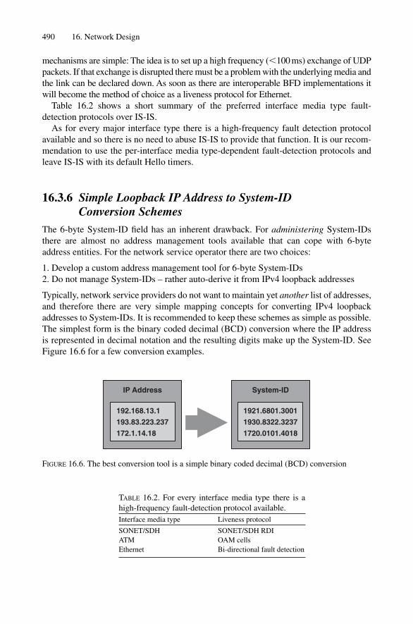
mechanisms are simple: The idea is to set up a high frequency (�100 ms) exchange of UDPpackets. If that exchange is disrupted there must be a problem with the underlying media andthe link can be declared down. As soon as there are interoperable BFD implementations itwill become the method of choice as a liveness protocol for Ethernet.
Table 16.2 shows a short summary of the preferred interface media type fault-detection protocols over IS-IS.
As for every major interface type there is a high-frequency fault detection protocolavailable and so there is no need to abuse IS-IS to provide that function. It is our recom-mendation to use the per-interface media type-dependent fault-detection protocols andleave IS-IS with its default Hello timers.
16.3.6 Simple Loopback IP Address to System-ID Conversion Schemes
The 6-byte System-ID field has an inherent drawback. For administering System-IDsthere are almost no address management tools available that can cope with 6-byteaddress entities. For the network service operator there are two choices:
1. Develop a custom address management tool for 6-byte System-IDs2. Do not manage System-IDs – rather auto-derive it from IPv4 loopback addresses
Typically, network service providers do not want to maintain yet another list of addresses,and therefore there are very simple mapping concepts for converting IPv4 loopbackaddresses to System-IDs. It is recommended to keep these schemes as simple as possible.The simplest form is the binary coded decimal (BCD) conversion where the IP addressis represented in decimal notation and the resulting digits make up the System-ID. SeeFigure 16.6 for a few conversion examples.
490 16. Network Design
TABLE 16.2. For every interface media type there is ahigh-frequency fault-detection protocol available.Interface media type Liveness protocol
SONET/SDH SONET/SDH RDIATM OAM cellsEthernet Bi-directional fault detection
192.168.13.1
193.83.223.237
172.1.14.18
IP Address System-ID
1921.6801.3001
1930.8322.3237
1720.0101.4018
FIGURE 16.6. The best conversion tool is a simple binary coded decimal (BCD) conversion
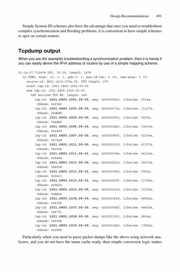
Simple System-ID schemes also have the advantage that once you need to troubleshootcomplex synchronization and flooding problems, it is convenient to have simple schemesto spot on certain routers.
Tcpdump outputWhen you are (for example) troubleshooting a synchronization problem, then it is handy ifyou can easily derive the IPv4 address of routers by use of a simple mapping scheme.
21:14:07.712478 OSI, IS-IS, length: 1478
L2 CSNP, hlen: 33, v: 1, pdu-v: 1, sys-id-len: 6 (0), max-area: 3 (0)
source-id: 6b01.c219.07fa.00, PDU length: 275
start lsp-id: 1921.6800.1001.00-00
end lsp-id: 1921.6800.1039.00-00
LSP entries TLV #9, length: 240
lsp-id: 1921.6800.1001.00-00, seq: 0x00000562, lifetime: 5014s,
chksum: 0x03dc
lsp-id: 1921.6800.1003.00-00, seq: 0x0000073a, lifetime: 31107s,
chksum: 0xdb8b
lsp-id: 1921.6800.1005.00-00, seq: 0x0000050c, lifetime: 5205s,
chksum: 0xa8bf
lsp-id: 1921.6800.1006.00-00, seq: 0x00000d20, lifetime: 30639s,
chksum: 0x2699
lsp-id: 1921.6800.1007.00-00, seq: 0x0000089f, lifetime: 52194s,
chksum: 0x74ad
lsp-id: 1921.6800.1011.00-00, seq: 0x00000319, lifetime: 61707s,
chksum: 0xc69e
lsp-id: 1921.6800.1011.00-01, seq: 0x0000008e, lifetime: 44126s,
chksum: 0x6e4d
lsp-id: 1921.6800.1013.00-00, seq: 0x000002c0, lifetime: 36610s,
chksum: 0xb05d
lsp-id: 1921.6800.1013.00-01, seq: 0x000000b0, lifetime: 5052s,
chksum: 0x0e21
lsp-id: 1921.6800.1013.00-03, seq: 0x0000029f, lifetime: 11790s,
chksum: 0x5bfa
lsp-id: 1921.6800.1033.00-00, seq: 0x00000318, lifetime: 11255s,
chksum: 0xbb6e
lsp-id: 1921.6800.1034.00-00, seq: 0x000006f4, lifetime: 48962s,
chksum: 0x634f
lsp-id: 1921.6800.1037.00-00, seq: 0x000005bf, lifetime: 44818s,
chksum: 0x4701
lsp-id: 1921.6800.1038.00-00, seq: 0x000013fc, lifetime: 8664s,
chksum: 0x93d4
lsp-id: 1921.6800.1039.00-00, seq: 0x000014b9, lifetime: 17862s,
chksum: 0x2894
Particularly when you need to parse packet dumps like the above using network ana-lyzers, and you do not have the name cache ready, then simple conversion logic makes
Design Recommendations 491

troubleshooting much easier. You are doing operations and support people a big favour ifyou avoid fancy and complicated System-ID schemes.
16.3.7 Align Throttling Timers Based on Global Network DelayIn most IS-IS implementations there are many timers that the network operator canadjust. In order to build a network that converges in the sub-second range, you often needto tweak those timers. The first thought may be the faster the better, however, that’s notalways the case. The typical throttles that are on by default are LSP origination and SPFdelay timers. Both JUNOS and IOS have a similar strategy to apply these throttles. Bothimplementations in common behave fast (almost no delay) for the first events in a series.However, the more quickly changes come, the more restrictive, and hence slower, the sys-tem behaves. This is achieved as a step function in JUNOS (the first three events are han-dled the fast way, and then the system immediately backs off to slow behaviour) and inIOS the router gets slower using an exponential curve. However, after three or four events,the system fully backs off to the slower behaviour. The art of good network design is tofind a healthy compromise so that the majority (95 per cent) of network events falls underthe fast window and you can take full advantage of the open throttles. Consider Figure16.7. When parts of a network fail, then there is always more than one LSP in flight. Oncethe link between Washington and New York breaks, both routers have to update theirLSPs. Ideally both LSPs arrive at all the routers at the same point in time.
Now you need to find a compromise between reasonably fast behaviour and waitinglong enough that you can catch and process an SPF run for all the LSPs belonging to aparticular network fault condition. How long is long enough? If you take a closer look athow an incident is processed, then the dominating element after mutual detection of alink-break is the propagation of the LSP. LSP propagation with reasonably fast circuits(greater then OC-3/STM-1 speeds) is mostly a function of the light-speed in a fibre plusthe LSP processing delay of routers. A good estimation for the average global floodingdelay is the worst case delay for network control traffic, plus the average hop count, multi-plied by 10 ms (average LSP processing delay).
Speed of light in fibres is about 200.000 km/s � 200 km/ms
Example 1: Continental network (diameter 4.000 km) spanning over average 6 routers.
4.000 km/200 km/ms � 6 * 10 ms � 20 ms � 6 * 10 ms � 80 ms
Example 2: Intercontinental network (diameter 30.000 km) spanning over an average of8 routers.
30.000 km/200 km/ms � 8 * 10 ms � 150 ms � 8 * 10 ms � 230 ms
It is recommended to change the LSP origination timer to a value that safely catches mostlink flaps. It should not be set too aggressively. A good recommendation here is 150 ms,which gives the router enough time to fully build an LSP no matter how large it may be.
It is recommended that you change the SPF delay timer based on the calculation forthe average processing and LSP propagation delay. A recommendation for delaying theSPF calculation is between 50 ms and 250 ms depending on network size.
492 16. Network Design
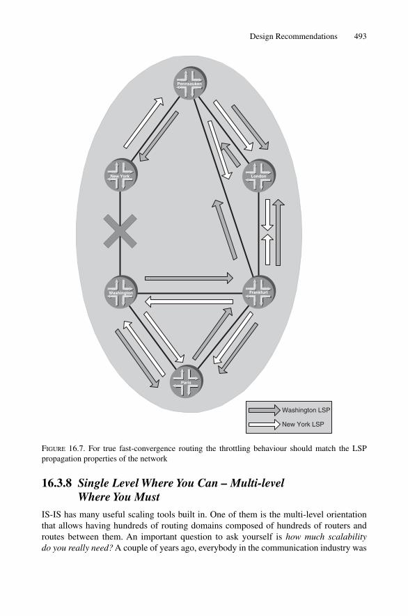
Design Recommendations 493
New York LSP
Washington LSP
Pennsauken
Frankfurt
London
Washington
New York
Paris
FIGURE 16.7. For true fast-convergence routing the throttling behaviour should match the LSPpropagation properties of the network
16.3.8 Single Level Where You Can – Multi-level Where You Must
IS-IS has many useful scaling tools built in. One of them is the multi-level orientationthat allows having hundreds of routing domains composed of hundreds of routers androutes between them. An important question to ask yourself is how much scalability do you really need? A couple of years ago, everybody in the communication industry was

494 16. Network Design
crazy over scaling, and even pushing the envelope for scalability was not enough forsome network service providers. Fortunately today some normality (some say sanity) hascome back to the industry, and most people now realize their true scaling needs and theassociated time-span until a next generation of network and network routers are needed.According to our experience, for the majority of networks, there is a simple design rule,which is to start with a single level of IS-IS. Unless your topological domain (IS-IS level)grows to a total number of beyond 800–1500 routers, there is no need to split things up.Do not be misled and think that splitting up a single level network into a multi-level net-work must automatically improve the scaling properties in all dimensions of that net-work. There are some examples where the additional complexity of processing twotopological domains may result in worse resource demands. A good case study is shownin Figure 16.8. In a given multi-level network, in order to still get optimal BGP routing,you need to turn on route leaking and propagate all /32 loopback routes. An individual /32prefix originating in Area 49.0100 Level 1 is leaked up to the Level 2 Area 49.0001 and,due to route leaking, it will be propagated down to Area 49.0200 Level 1. If you now sup-pose (for example) that the San Francisco router goes down, then the timing propertiesof all the individual operations are:
1. Flood inside Level 1 Area 49.0100 (20ms)2. Atlanta: SPF delay, local SPF calculation, leak to Level 2, LSP build delay
(100 ms � 10 ms � 100 ms)3. Flood inside Level 2 Area 49.0001 (20 ms)4. Amsterdam: SPF delay, local SPF calculation, leak to Level 1, LSP build delay
(100 ms � 10 ms � 100 ms)5. Flood inside Level 1 Area 49.0200 (20 ms)6. Stockholm: SPF delay, local SPF calculation (10 ms � 10 ms)
If you sum up all of these operations then the total Level-1-to-Level-1 convergencetakes 500 ms compared to the single level flooding delay, plus SPF delay and SPF calcu-lation (130 ms). Although the network should behave better, it actually got worse by afactor of 4 in terms of convergence.
Typically, you start a green-field design with a single Level-2 IS-IS network. You mayask why to start with Level 2 first and not with Level 1, and extend it later to a Level-2network? Figure 16.9 shows the two transitioning examples. On the top, the migrationfrom a Level-2 to a multi-level network works without any disruption at all. Only twolevel settings need to be changed. On the bottom the conversion from a Level-1 to Level-2 is troublesome, because Level-1 adjacencies require that the Area address matches onboth ends, and in order to create several Level-1 areas you need to renumber the areasand touch every router. This means that for a short time you must disrupt your service. Inthe top example we assume that the network administrator has allocated the appropriatedistinct Area-IDs so that they can change the level anytime. In Level 2 routing, differentArea-IDs are tolerated – the Area-ID does not need to match. A little piece of toleranceis generally a good recipe for easy transitioning, and here it helps to be able to renumberthe Area-IDs without any disruption. That is good news, as you do not need to worryabout addressing from the start. You can at a later stage change the entire IS-IS Areaaddressing and add anything at any time.

495
Fra
nkf
urt
Lo
nd
on
Was
hin
gto
n
New
Yo
rk
Par
is
Mia
mi
San
Jo
seV
ien
na
Mu
nic
h
Am
ster
dam
Atl
anta
San
Fra
n
Are
a49
.010
0A
rea
49.0
001
Leve
l 2-o
nly
Pen
nsa
uke
n
Sto
ckh
olm
Are
a 49
.020
0
FIG
UR
E16
.8.I
n a
two
leve
l IS-
IS n
etw
ork
prop
agat
ion
thro
ugh
all l
evel
s do
es s
low
dow
n co
nver
genc
e
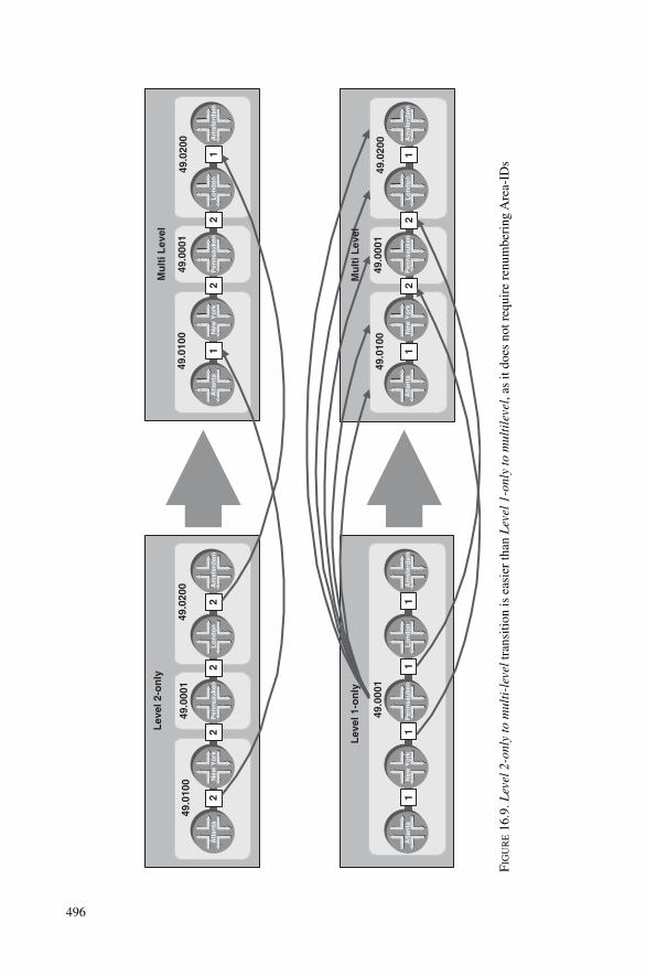
22
22
11
11
12
21
12
21
Am
ster
dam
Lo
nd
on
Atl
anta
New
Yo
rkA
mst
erd
amL
on
do
nA
tlan
taN
ew Y
ork
Am
ster
dam
Lo
nd
on
Atl
anta
New
Yo
rkA
mst
erd
amL
on
do
nA
tlan
taN
ew Y
ork
49.0
100
Pen
nsa
uke
n
49.0
001
Lev
el 2
-on
ly
49.0
200
Mu
lti L
evel
49.0
100
Pen
nsa
uke
n
49.0
001
49.0
200
Lev
el 1
-on
ly
49.0
001
Pen
nsa
uke
n
49.0
100
Pen
nsa
uke
n
49.0
001
49.0
200
Mu
lti L
evel
FIG
UR
E16
.9. L
evel
2-o
nly
to m
ulti
-lev
eltr
ansi
tion
is e
asie
r th
an L
evel
1-o
nly
to m
ulti
leve
l ,as
it d
oes
not r
equi
re r
enum
beri
ng A
rea-
IDs
496

497
In the case where you have a massive number of routers, or certain smaller routerswith limited CPU and memory resources, you may decide to run a multi-level network.Best current practice is to have a point of presence (POP) where all the internal routers,reflectors, access servers and servers are routed using Level-1 routing. One or two L1L2routers provide core access as illustrated in Figure 16.10.
Note the link between the two core routers – both a Level 1 and a Level 2 adjacency isestablished between the core routers. This is an example where one physical link can beshared between two IS-IS topologies. The purpose of the link is for backup in case thereis a topology break either in the core or in the edge.
A POP-centric design has the nice advantage that there is a clean separation betweencore and edge, which is also typically run by different teams at a service provider. Sothere are almost no incidents where the edge-router department at a service providermodifies core-router related configuration and vice versa (some call this the missingcross talk problem). At large service providers it often turns out that technology has tofollow organizational requirements. The POP centric design perfectly reflects that idea.
16.3.9 Do Not Rely on Default RoutesDefault routes are a nice tool for scaling the network, particularly for routers that do nothave the CPU and memory resources to load and hold full BGP Internet routing tables.
POP design
49.0100
49.0900
2 2
12
1
11 11 1
1
1
L2
L1L2
L1
L2
L1L2
L1 L1 L1
FIGURE 16.10. Common multi-level designs have two L1L2 routers and intra-POP routing is provided using L1 routing
Design Recommendations 497

498
However, in an Internet environment, any form of default routing disturbs more than itdoes good. By introducing a default route, you are also keeping out more specific entriesthat may contain valuable information and harm network properties like convergence.Consider Figure 16.8, where San Francisco and Stockholm are BGP speakers in differ-ent areas. In order to calculate a meaningful metric between the two BGP speakers theL1L2 (Atlanta, Amsterdam) routers leak all /32 addresses down in the Level 1. Next,suppose that the San Francisco router becomes unreachable through a topology break inthe core. The Atlanta router builds a new Level 2 LSP, which does not contain SanFrancisco’s loopback IP address. Amsterdam quickly notices that San Francisco speakeris unreachable within the Level 2 domain and does not leak the prefix further down inLevel 1. The Stockholm Level 1 router now tries to resolve the BGP routes through anyother IGP route, which is in this case the default route. The default route is locally gen-erated by all L1 IS-IS routers because the L1L2 routers have the Attached (ATT) Bit setas part of their Level 1 LSP. BGP thinks that the other end is still reachable and does notrealize (due to the default route) that the San Francisco router is not available anymore.If there is a direct iBGP connection between San Francisco and Stockholm, then as a lastresort the BGP session will time out. However, if the San Francisco prefixes are learnedvia a BGP Route Reflector infrastructure, then there is no way for Stockholm to realizethat a remote BGP speaker is down.
Most router implementations have a configuration option that ignores the ATT Bit inLevel 1 LSPs and hence suppresses generation of a local default route. Going back toFigure 16.8, that means that all Level 1 BGP speakers are configured not to listen to ATTBits. Then the resolver immediately knows that there are no alternate paths available, andthe BGP routes are immediately withdrawn and alternate paths become active.
Try to design your core network so that it does not rely on a default route in any sin-gle place. Try to avoid any form of explicit 0/0 route embedded in IP Reachability TLVsand actively filter those routes on any L1L2 choke point. Also try to control all implicitdefault routes that may be locally generated through the ATT Bit. If there are no defaultroutes in the core network, then your end-customers will greatly benefit from theimproved network convergence.
16.3.10 Use Wide-metrics OnlyBoth IS-IS implementations discussed in this book ship with a compatibility mode whereboth old-style and wide-style metrics are advertised in a router’s LSP. That dual supportfor both old-style TLV #2, #128, #130 and new-style TLV #22, #135 comes at some cost.The drawback is that the metrics of the old-style topology and the new-style topologyhave to stay congruent in order to produce non-divergent topologies. The clipping ofmetrics makes the new-style metrics, although they have a broader metric width, behavelike the old-style 6-bit metrics and does not carry any advantage despite being compat-ible at all costs. The default settings of JUNOS and IOS are either small-metrics andcompatibility mode. It is recommended to turn off generation of any form of old-styleTLV. All recent routing software has support for wide metrics, and there are no disad-vantages to suppressing any old-style TLVs. Most real-world IS-IS router configurationsturn off small metric generation and it is just a matter of time before router vendors pick
498 16. Network Design

Design Recommendations 499
up the deployed reality and it becomes the default behaviour in JUNOS and IOS. Oftendownwards compatibility is preferred when changing defaults, and generally softwareengineers are reluctant to change behaviour. However, downward compatibility at allcosts is not always the smartest way to evolve a protocol.
16.3.11 Make Use of the Overload BitThe Overload (OL) Bit was intended to be an indicator that a router ran out of resources.Today it is used for administration purposes in order to avoid persistent transit traffic orto avoid the delay of transit traffic until the BGP mesh has been brought up. It is a con-venient tool to avoid traffic flowing over certain nodes. The SPF calculation tries to findthe shortest path between a pair of nodes in the IS-IS topology, however, sometimes theshortest path through a node may not be desired at all, particularly when it has to berouted over small-bandwidth routers serving (for example) as a route reflector. ConsiderFigure 16.11, where the core link between Router Munich and Router Frankfurt fail andthe traffic can be re-routed over the dual homed route reflector. However, the route reflec-tor is just attached with OC-3/STM-1 link speed, and if inadvertently abused as a transitrouter, may fully congest those links. Good connectivity of route reflectors is a desiredproperty and multi-homing is often a way of achieving this.
If you statically set the Overload Bit, then all routers consider your route reflectors asnon-viable transit paths for passing traffic. Any Edge Node, such as data centre accessrouters, may be candidates for setting the Overload Bit statically.
16.3.12 Turn on HMAC-MD5 AuthenticationIS-IS is believed to be an inherently secure protocol because it natively runs on OSIReference Model Layer 2 and hence an attacker cannot inject any malicious packetsfrom remote locations, as can be done with the IP routing protocols. But there is no such
Routereflector
30% loadoc-48
1% loadoc-3
1% loadoc-3
FrankfurtMunich
RR
Overload
FIGURE 16.11. Static setting of the Overload Bit saves the route reflector from forwarding transittraffic
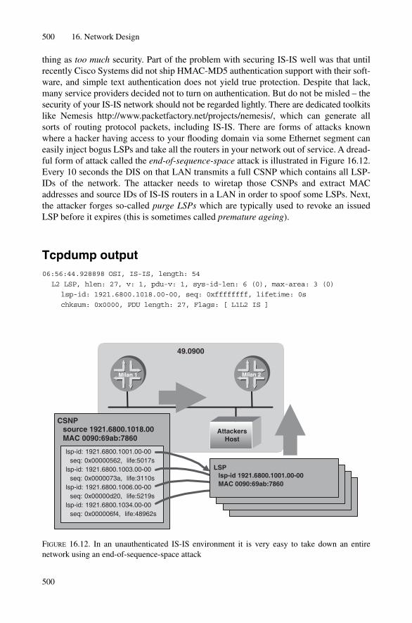
500 16. Network Design
500
thing as too much security. Part of the problem with securing IS-IS well was that untilrecently Cisco Systems did not ship HMAC-MD5 authentication support with their soft-ware, and simple text authentication does not yield true protection. Despite that lack,many service providers decided not to turn on authentication. But do not be misled – thesecurity of your IS-IS network should not be regarded lightly. There are dedicated toolkitslike Nemesis http://www.packetfactory.net/projects/nemesis/, which can generate allsorts of routing protocol packets, including IS-IS. There are forms of attacks knownwhere a hacker having access to your flooding domain via some Ethernet segment caneasily inject bogus LSPs and take all the routers in your network out of service. A dread-ful form of attack called the end-of-sequence-space attack is illustrated in Figure 16.12.Every 10 seconds the DIS on that LAN transmits a full CSNP which contains all LSP-IDs of the network. The attacker needs to wiretap those CSNPs and extract MACaddresses and source IDs of IS-IS routers in a LAN in order to spoof some LSPs. Next,the attacker forges so-called purge LSPs which are typically used to revoke an issuedLSP before it expires (this is sometimes called premature ageing).
Tcpdump output06:56:44.928898 OSI, IS-IS, length: 54
L2 LSP, hlen: 27, v: 1, pdu-v: 1, sys-id-len: 6 (0), max-area: 3 (0)
lsp-id: 1921.6800.1018.00-00, seq: 0xffffffff, lifetime: 0s
chksum: 0x0000, PDU length: 27, Flags: [ L1L2 IS ]
49.0900
lsp-id: 1921.6800.1001.00-00 seq: 0x00000562, life:5017slsp-id: 1921.6800.1003.00-00 seq: 0x0000073a, life:3110slsp-id: 1921.6800.1006.00-00 seq: 0x00000d20, life:5219slsp-id: 1921.6800.1034.00-00 seq: 0x000006f4, life:48962s
CSNPsource 1921.6800.1018.00MAC 0090:69ab:7860
LSPlsp-id 1921.6800.1001.00-00MAC 0090:69ab:7860
Milan 1 Milan 2
AttackersHost
FIGURE 16.12. In an unauthenticated IS-IS environment it is very easy to take down an entirenetwork using an end-of-sequence-space attack

The LSP in question does not contain any TLV at all. Note the sequence number0xffffffff – this is the highest sequence number possible. When the packet is floodedthrough the Level 2 domain, it is ultimately received by the router with System-ID1921.6800.1018. This router realizes that it was not the originator of that packet. Whenevera router sees non-self originated LSP carrying their very own System-ID number, they tryto increment the sequence number and re-issue an accurate version of their LSP. However,that is not possible any more because the sequence space is exhausted. ISO 10589 requiresthat a router that reaches end-of-sequence space goes dormant for a max-LSP-age period.Most routers are configured with a max-LSP-age of 65,535 seconds, which is 18.2 hours.
Can you imagine the turmoil if all your routers go dormant for 18.2 hours and youriBGP distribution mesh falls to pieces? And it does not take much in the way of resourcesto achieve that – just an open Ethernet segment and a possibility to inject spoofed packets.Realize the small effort involved: no brute force Denial of Service attack is needed totake down an entire service provider’s network, just a few hundred spoofed LSPs that caneasily be generated with common security tools.
Security through obscurity does not generally work well. Running an IS-IS networkwithout proper authentication using cryptographically strong algorithms like HMAC-MD5 is grossly negligent. Given the potential threat of an attack to the IGP, every net-working architect should be concerned and it should be mandatory to turn on IS-ISstrong authentication.
16.3.13 Turn on Graceful Restart/Non-stop ForwardingOnce the IGP fails, a network is literally breaking into pieces. If the IGP goes down, theBGP mesh will fail, and subsequently routing and forwarding is severely disrupted.Modern routing software is written where some components share a common fate. If, forinstance, there is a bug in the resolver, then the entire routing process will crash. After acouple of seconds a watchdog component may find out that the process has been fallingon its face and restart the faulty routing sub-system. The software will behave like on acold start and send out IS-IS Hellos with no neighbour-related state mentioned in theadjacency-related TLVs (#6, #240), which will cause neighbouring routers to drop thoseadjacencies. Graceful restart/non-stop forwarding helps to protect the IGP subsystem incase of a failure. After being restarted, the router will request a graceful restart by settingthe Restart Request Bit in TLV #211, which will cause neighbouring routers that supportgraceful restart/non-stop forwarding not to take down adjacencies for a grace-period (typ-ically 180 seconds). Graceful restart/non-stop forwarding is all about tolerance of nodesthat have failed previously. It is recommended to turn graceful restart/nonstop forwardingon wherever possible. You gain more availability of your network in case of local softwarefailure and the problem does not spread network-wide anymore.
16.4 Conclusion
The biggest improvement for getting to a scalable IS-IS network is separating IP reach-ability information from IS reachability information and do not let IS-IS carry IP routes,
Conclusion 501
502 16. Network Design
except for the bare minimum needed to bring up the iBGP transport mesh. Once theiBGP transport mesh has been brought up BGP carries all IP information including link-local IP sub-net prefixes. That design choice is no real choice – it is paramount – all theother options depend on what you expect from the network and what is doable with theprevailing hardware/ software combination. Ultimately, one has to listen to what end-customers are expecting and what kind of services have to be modelled on top of thatbackbone. For good network designs there are two important insights. First, you alwayshave to make a compromise. Networks are complex and changes of any kind have multi-dimensional impact. If you optimize on one direction then you deliberately have to jeop-ardize the other. So pick carefully which of the three areas you want to optimize on:scalability, stability or convergence. While it would be a highly desirable goal to maxi-mize all three, in practice you can only optimize on two. The second insight is an old ruleof systems design – keep it simple. Before exploring complex matters of route leaking andmulti-level designs, first answer the question as to whether you really need all that com-plexity. Would the network work even if you go with a single level design, and what wouldbe the overall scalability impact? Practical experience says that modern IS-IS implemen-tations are more scalable than people think, and keep some sanity, sometimes networkdesigners try to seek solutions for non-existent problems.

17
Future of IS-IS
503
Writing a book about IS-IS is a never-ending task. During the writing of this book a lotthat was originally planned for this future chapter got implemented in routing softwareand is now available and deployed in the Internet. It became clear to the authors thatwhatever we put into this chapter would just be a snapshot of the thoughts and publishedInternet drafts at one particular time. You will find a lot of proposals here that may maketheir way into final products, and some ideas that will ultimately be tossed aside. Thischapter is about a whole spectrum of IS-IS extensions, ranging from very ambitious pro-jects like Generalized MPLS (G-MPLS) to very pragmatic ones like iBGP auto-discovery.However, this chapter is not limited to just a snapshot of the Internet drafts in mid 2004. TheIS-IS universe is ever-expanding, and we will have to ask if it is a legitimate concern toenhance the IS-IS protocol at all costs, particularly for functions that it was not ori-ginally designed for.
17.1 Who Should Evolve IS-IS?
IS-IS is evolved by different standards bodies. The IETF is supposed to refine specifica-tion of IP-related extensions, and the ITU ought to take care of any modifications to thebase specification. As part of the agreement between the IETF and ITU, there is a div-ision of the assignable TLV space. The ITU is supposed to assign the lower 127 TLVs,and the IETF has been given the upper 127 TLVs. However, as shown in Chapter 13, “IS-IS Extensions”, the IETF got away from their home turf and published specifications thatare outside their assigned responsibilities – the Multi Topology Extensions and allgeneric IS-IS functions like Traffic Engineering, Authentication and Checksummingrelated TLVs (222, 22, 10, 12) violate this division. These TLVs have been specified andsubmitted in a time-to-market fashion, mostly to overcome the slow decision-makingprocess within the ITU. There are voices in the IETF that would either force the two stan-dards bodies to work together, or completely transfer responsibility for the IS-IS protocolfrom the ITU-T to the IETF. Dr Tony Li, once, IETF ISIS-WG chair, proposed just thismerging once on the IETF ISIS-WG mailing list.
Let me offer a germ of an idea: As has been pointed out, there is a great deal of overlap betweenthe actual folks doing the work in both organizations. No matter where we host it, it’s the samefolks, doing the same thing. Why then, does it really matter, where the group is hosted? Why nothave just one joint, integrated working group, which reports to two bodies? This way, the grouphas the clear authority to issue definitive documents. These documents get published as BOTH ISOstandards and RFCs.
The involvement of different standards bodies raises a plethora of issues. Because theIETF is not the “owner” of IS-IS, none of its documents go on the IETF standards trackprocess. The standards track is a multi-year process that ensures protocol maturity andinteroperability between different vendors. All the different stages of the maturity processis documented as RFCs and at the end of the standards track process there is promotionof the protocol to an Internet Standard, which not many documents achieve. As soon asthe Internet Standard status is reached, the document becomes a normative reference inthe ITU sense. Although the ITU’s standards track process may take several years, onecould argue that the ITU is much faster in this respect. The difference between the twostandardization bodies is how they approach and handle standardization. In the IETF,things are pretty much evolution driven: the IETF defines a problem, Internet drafts getpublished and in many cases the equipment vendors ship software based on the Internetdrafts, which are at this point not normative references at all. This process has the advan-tage of getting a new IS-IS feature deployed quickly, sometimes within six months (at therisk of changing the software several times unless the Internet draft has matured). In theITU, there is much more emphasis on getting the first document flawless through rigidreviews and (of course) plenty of time. The ITU believes that specifications have to befinalized before they can be used in actual product shipments. While that approach ismuch more “clean slate”, it runs the risk of missing the market during all these time-consuming review cycles. Meanwhile, the ITU has practically resigned from the task ofevolving IS-IS. All of the work is done in the IETF. But because the ITU still formally ownsthe base protocol, the IETF must not publish any IS-IS-related RFCs as standards trackRFCs, but rather as informational RFCs. Informational RFCs do not have the status of anormative specification – they are just supposed to make sure that things are documented.However, there is a paradox in that the ISIS-WG is the only valid source for further IS-ISdevelopment, and yet has to publish all IS-IS extensions as non-normative documents, theinformational RFCs. Moreover, the ITU refers to the published IS-IS informational RFCs,and therefore is blessing the “informational” RFCs as normative references!
The double standardization, or lack of it, remains a real problem in the IS-IS community.And there are no signs that the situation will get better. Reunion of the IP and opticallayer through G-MPLS will be the next severe challenge for the two IS-IS standardiza-tion bodies. Then there will be a full clash in terms of responsibility. Transmission net-works are a true domain of the ITU, and recently all the IS-IS control plane-relatedextensions have been done at the ISIS-WG inside the IETF. It is the authors’ opinion thatthe ITU should formalize what is the de facto status today and transfer responsibility forIS-IS to the ISIS-WG in the IETF and promote all IS-IS related extensions to IETF stand-ards track documents.
17.2 G-MPLS
A networking stack in a service provider’s network looks quite different today than itlooked not long ago. Figure 17.1 shows a typical networking stack of the 1990s: there areseveral layers of networking protocols transporting the IP application. IP is wrapped on topof ATM, which performed traffic engineering functions. Next, there is a SONET/SDH
504 17. Future of IS-IS
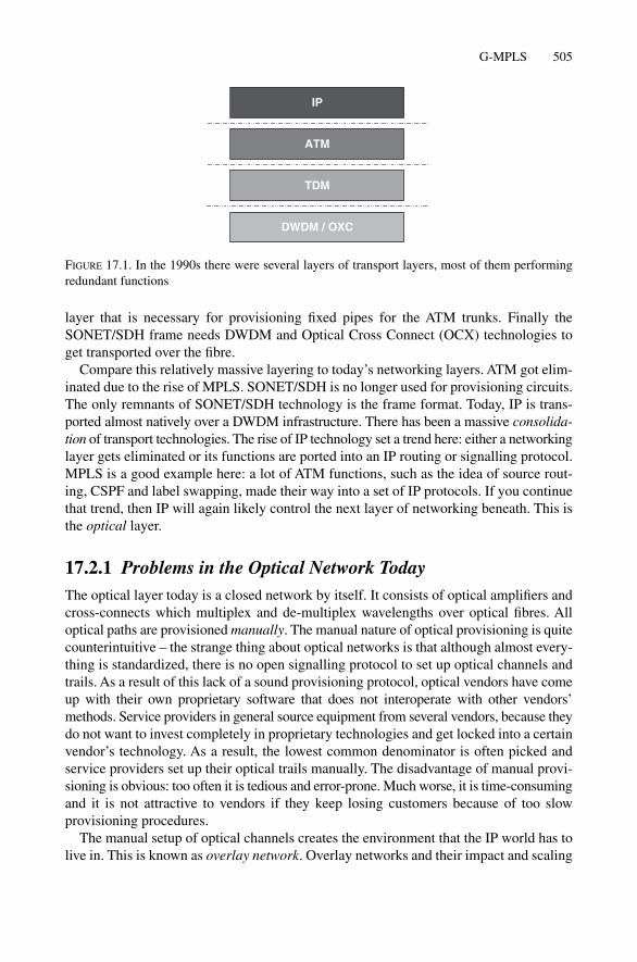
layer that is necessary for provisioning fixed pipes for the ATM trunks. Finally theSONET/SDH frame needs DWDM and Optical Cross Connect (OCX) technologies toget transported over the fibre.
Compare this relatively massive layering to today’s networking layers. ATM got elim-inated due to the rise of MPLS. SONET/SDH is no longer used for provisioning circuits.The only remnants of SONET/SDH technology is the frame format. Today, IP is trans-ported almost natively over a DWDM infrastructure. There has been a massive consolida-tion of transport technologies. The rise of IP technology set a trend here: either a networkinglayer gets eliminated or its functions are ported into an IP routing or signalling protocol.MPLS is a good example here: a lot of ATM functions, such as the idea of source rout-ing, CSPF and label swapping, made their way into a set of IP protocols. If you continuethat trend, then IP will again likely control the next layer of networking beneath. This isthe optical layer.
17.2.1 Problems in the Optical Network TodayThe optical layer today is a closed network by itself. It consists of optical amplifiers andcross-connects which multiplex and de-multiplex wavelengths over optical fibres. Alloptical paths are provisioned manually. The manual nature of optical provisioning is quitecounterintuitive – the strange thing about optical networks is that although almost every-thing is standardized, there is no open signalling protocol to set up optical channels andtrails. As a result of this lack of a sound provisioning protocol, optical vendors have comeup with their own proprietary software that does not interoperate with other vendors’methods. Service providers in general source equipment from several vendors, because theydo not want to invest completely in proprietary technologies and get locked into a certainvendor’s technology. As a result, the lowest common denominator is often picked andservice providers set up their optical trails manually. The disadvantage of manual provi-sioning is obvious: too often it is tedious and error-prone. Much worse, it is time-consumingand it is not attractive to vendors if they keep losing customers because of too slow provisioning procedures.
The manual setup of optical channels creates the environment that the IP world has tolive in. This is known as overlay network. Overlay networks and their impact and scaling
G-MPLS 505
ATM
DWDM / OXC
IP
TDM
FIGURE 17.1. In the 1990s there were several layers of transport layers, most of them performingredundant functions

damage to link-state routing protocols were explained in Chapter 14, “Traffic Engineeringand MPLS”. The cost of transporting IP data is today increasingly questioned, and themain problem of the high cost of IP transport is the lack of any real underlying topologythat is tuned to IP.
17.2.2 Cost of TransportConsider Figure 17.2, where the underlying optical topology consisting of optical ampli-fiers and cross-connects that connects the higher level IP topology is much more diverseand complex. Although to the IP topology, the trail from London to Frankfurt appears tobe attractive, considering the full network stack reveals a different picture. It is quiteexpensive to relay IP traffic between London and Frankfurt as the traffic has to passthrough several regeneration stages on its way between the two cities. The overall cost oftransmission is dominated by the number of regenerator hops of the optical topology. Ifthe IP world would have had the full picture of the underlying topology, it could producemore accurate IP costs that would reflect the real cost of transmission.
G-MPLS fixes the above two problems: it offers a unified routing and signalling layerfor both the IP and the optical world. First, IP nodes can gather the structure of the optical topology and calculate the cost for IP transport accordingly. Next, optical com-ponents can signal optical channels using a standardized protocol (RSVP-TE).
Transitioning from the prevailing method of running the optical and IP network as dis-joint networks to a full G-MPLS model requires three main migrations.
1. Transitioning from pure manual provisioning to a full signalled environment2. Transitioning from the world of vendor proprietary protocols to the IP world of open
protocols3. Opening the optical layer to devices to the routing layer
Taking those three steps requires a lot of changes. Not every network service provideris willing to take all three steps at once. There is more demand for a constant evolutionof networks than a rapid revolution, with the admirable goal of not destabilizing the net-work. Also, consolidation of networking elements has to pay off at the end of the day.Further reduction of operating expenses is the main driver for the G-MPLS ideas. However,many teams at service providers, especially optical groups, fear that their jobs may becomeobsolete if they pass on too much control to a consolidated, unified control plane. Today,full-scale G-MPLS causes much anxiety and so many service providers try to split up themigration into a two-step migration model. The first migration step is called the overlaymodel and the second step is called the peer model. The two models do not contradict eachother, they can be seen more as complementary steps. Many optical vendors use the termhybrid model to reflect the fact that both models can be implemented at the same time.
17.2.3 Overlay (UNI) G-MPLS ModelThe overlay model can best be characterized taking migration Step 1 and 2 (outlinedabove) towards G-MPLS, but not taking Step 3. So the optical topology is beefed up andnow encompasses dynamic signalling using IP routing and signalling protocols; however,
506 17. Future of IS-IS
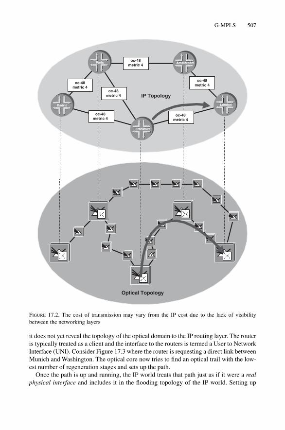
it does not yet reveal the topology of the optical domain to the IP routing layer. The routeris typically treated as a client and the interface to the routers is termed a User to NetworkInterface (UNI). Consider Figure 17.3 where the router is requesting a direct link betweenMunich and Washington. The optical core now tries to find an optical trail with the low-est number of regeneration stages and sets up the path.
Once the path is up and running, the IP world treats that path just as if it were a realphysical interface and includes it in the flooding topology of the IP world. Setting up
G-MPLS 507
Optical Topology
IP Topology
oc-48metric 4
oc-48metric 4
oc-48metric 4
oc-48metric 4
oc-48metric 4
oc-48metric 4
Frankfurt
London
Paris Amsterdam
Madrid
FIGURE 17.2. The cost of transmission may vary from the IP cost due to the lack of visibilitybetween the networking layers

many optical trails using UNI-like signalling creates about the same problem ATM net-works had, and is the reason most ATM networks have now been abandoned. As UNI inter-faces, the optical trails make you create another overlay network, only this time on theoptical layer. Chapter 14, “Traffic Engineering and MPLS”, gives some reasons as to howoverlay networks stress the IGPs and often produce strange routing decisions. Hiding thetopology creates many support-related problems too. If the IP team does not know where
508 17. Future of IS-IS
Optical Topology
IP Topology
oc-48metric 4 oc-48
metric 4
oc-48metric 4
oc-48metric 4
oc-48metric 4oc-48
metric 4
Optical UNIInterface
Optical UNIInterface
Frankfurt
London
Paris Amsterdam
Madrid
FIGURE 17.3. By connecting the router with a UNI interface the optical topology is not revealed tothe IP routers

their core trunks are routed, the Network Operations Center will have a hard time cor-relating local link faults to the global faults of the LSP mesh. Therefore it is essential toconvey how the real optical path looks to the routers. Unfortunately, due to the UNI-likeseparation between optical network and client (router), there is little room for giving suchfeedback. A place where this kind of information could live is the Route Record Object(RRO) that should return the real path that a label switched path is taking. Researchgroups have identified the modifications to the RRO necessary to accommodate opticalpaths that have been computed and set up outside the IP domain. It remains questionablefrom a philosophical standpoint why at first hiding everything, and then eventually dis-closing it, is a consistent and repeated model, but an odd one to base a networking archi-tecture upon.
The overlay (UNI) model is a nice start for deploying the new G-MPLS routing andsignalling protocols. It gives the optical engineers exposure to the IP world of addressing,signalling and routing, which is certainly a non-technical challenge. As soon as you wantto roll it out on a larger scale, the inherent technical scaling limitations of optical net-works are revealed. You clash completely with the restrictions of overlay networks and geta déjà vu of recent times when ATM overlay cores were pushing the limits of existingtechnology, a whole seven years ago.
In order to not repeat the mistakes from the past, the full-scale G-MPLS deploymentsneed to have complete vision into the underlying optical topology, which is what the peerG-MPLS model describes.
17.2.4 Peer G-MPLS ModelThe G-MPLS peer model represents the full conclusion of all three migration steps. Theidea is that all components in a network, including
• Packet switches (routers)• TDM switches (SONET/SDH cross-connects (TXC))• Optical switches (lambda and fibre cross-connects (OXC))
all run an instance of a common routing and signalling protocol. The common routingprotocol could be enhanced versions of IS-IS or OSPF. It is the authors’ opinion that IS-ISfinally will prevail as the routing protocol of choice in the unified routing cloud. IT willmost likely be IS-IS mainly because IS-IS has been successfully deployed on a larger scalein IP networks, but also because the core IP routing teams do not want to run the risk ofdestabilizing the network by introduction of a new protocol. There is a belief in the mar-ket that IS-IS scales much better than anything else, but that belief is largely because ofimplementation issues. The fact is that the only well-implemented, multivendor IGP todayis IS-IS. By continuing on its evolutionary path, IS-IS will remain, at least in the mindsof network service operators, the IP IGP that scales, and therefore will likely be the can-didate for a deployment of thousands of G-MPLS nodes in a given domain.
In G-MPLS each component in the network runs a control plane either in-band or out-of-band. That is a shift from pure IP routing, where routing protocols were alwaysrunning on an in-band channel (in-band just means the signalling and traffic travel on thesame channels). There is an Internet draft (draft-ietf-ccamp-lmp) which describes the
G-MPLS 509
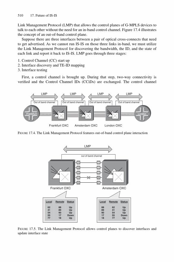
Link Management Protocol (LMP) that allows the control planes of G-MPLS devices totalk to each other without the need for an in-band control channel. Figure 17.4 illustratesthe concept of an out-of-band control plane.
Suppose there are three interfaces between a pair of optical cross-connects that needto get advertised. As we cannot run IS-IS on those three links in-band, we must utilizethe Link Management Protocol for discovering the bandwidth, the ID, and the state ofeach link and report it back to IS-IS. LMP goes through three stages:
1. Control Channel (CC) start up2. Interface discovery and TE-ID mapping3. Interface testing
First, a control channel is brought up. During that step, two-way connectivity is verified and the Control Channel IDs (CCiDs) are exchanged. The control channel
510 17. Future of IS-IS
Frankfurt OXC London OXCAmsterdam OXC
Out of band channel Out of band channel Out of band channel Out of band channel
LMP LMP LMP LMP
Frankfurt London
FIGURE 17.4. The Link Management Protocol features out-of-band control plane interaction
Frankfurt OXC Amsterdam OXC
out of band channel
62
41
54
55
77
88
89
90
17
18
Local
6241545577
Remote
8889901718
Status
UpUpUp
DownUp
Local
8889901718
Remote
6241545577
Status
UpUpUp
DownUp
LMP
FIGURE 17.5. The Link Management Protocol allows control planes to discover interfaces andupdate interface state

additionally features high-speed detection of control plane failures and generates Hellomessages typically at the pace of every 150 ms.
Figure 17.5 illustrates the next step, where both systems report and mutually discoverthe interfaces as well as the TE-IDs of those interfaces. Part of this discovery phase is alsoto find out about the interface switching type, which could be packet, TDM or lambda-based. Finally, all the interfaces are verified and reported either as up or down.
Once IS-IS learns about all the interfaces and interface properties such as bandwidth,TE-ID, and switching capability it has enough information to update its link-state PDU andadvertise the link properties between the two switching nodes as sub-TLVs in the extendedIS-Reach TLV #22. In the next section there is a list of these sub-TLVs and their contents.
IS-IS now has full visibility of all interfaces in the network and the interface switch-ing capabilities. However, relaying of user traffic is not yet possible at this point. Thehigher switching layers like the packet or TDM switching devices still rely on the bring-ing up of the optical switching layers first. Consider Figure 17.6 for an example of howthe optical switching layers are brought up.
1. The TDM cross-connect in Paris signals that it needs a lambda (wavelength) capableof transporting an OC-192c/STM-64 (10 Gbps) frame to Amsterdam via RSVP-TE.As the cross-connect in Paris now has complete knowledge of the optical topology, itcould also predetermine the route or base it on constraints like hop count, delay, etc.
2. The lambda between Paris and Amsterdam can now be used for carrying higher layertraffic. In order to make it available to the higher switching layers, the routers use a technique called forwarding adjacencies. Chapter 14, “Traffic Engineering andMPLS”, contained a short introduction to forwarding adjacencies and an example ofhow an existing TE tunnel is re-advertised in the IS-IS topology. In G-MPLS a similartechnique is used. Whenever a lower switching layer sets up a tunnel, it re-advertisesthe TE-Tunnel in the higher switching layer. The forwarding adjacency needs to bemarked so that the lambda switching layer does not “see” the adjacency anymore (for the reasons why this must happen, see Chapter 14). G-MPLS marks forwardingadjacencies by means of the Switching Capability field. In the example, the lambdatunnel between the TDM cross-connects gets advertised as an OC-192c/STM-64 pipethat has TDM switching capabilities. Each lambda cross-connect will ignore any adja-cency of a lower switching layer for consideration of LSP setups at its own level in thenetworking hierarchy.
3. The router in Madrid signals via RSVP that it needs a TDM channel of SONET/SDHOC-48c/STM-16 speed (about 2.5 Gbps) to London and provides the desired path.After successful path establishment the TE tunnel is again re-advertised as a higherswitching layer forwarding adjacency. This time the signalled OC-48c/STM-16 pipegets re-advertised and marked as an interface with packet switching capabilities. Thiswill “poison” it for any TDM switch and make it usable only by other routers.
4. The router now has a packet switching-capable tunnel between Madrid and London.The final step is to signal a packet Label Switched Path from a local POP router in theG-MPLS cloud (Madrid in this case) to any other (London) via RSVP and make use ofthe additional OC-48c/STM16 pipe by forwarding IP traffic down the packet switchingLabel Switched Path. Note that the IP routers in Paris, Amsterdam, Frankfurt are still
G-MPLS 511

512 17. Future of IS-IS
TDM Topology
Optical Topology
IP Topology
Paris Amsterdam
Madrid
Frankfurt
London
oc-48metric 4
Paris Amsterdam
Madrid London
4
Frankfurt
London
Paris Amsterdam
Madrid
2
3
1
FIGURE 17.6. Each provisioned tunnel in the switching hierarchy N is represented as a forwardingadjacency of switching capability N � 1
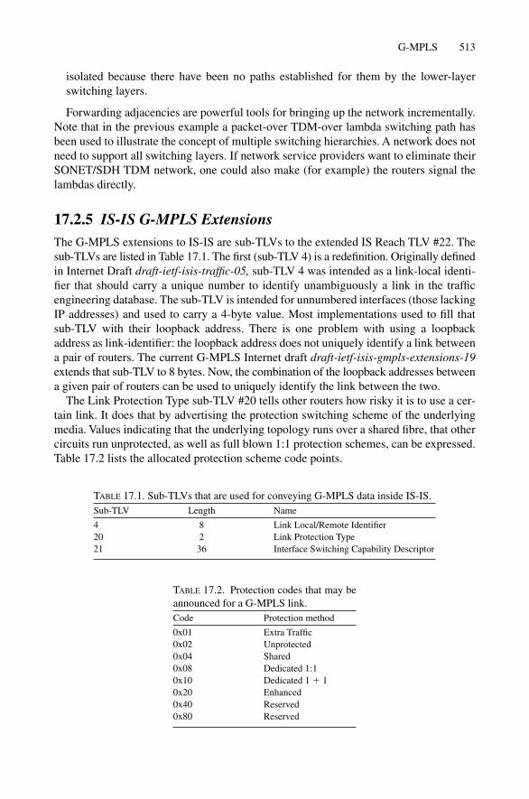
isolated because there have been no paths established for them by the lower-layerswitching layers.
Forwarding adjacencies are powerful tools for bringing up the network incrementally.Note that in the previous example a packet-over TDM-over lambda switching path hasbeen used to illustrate the concept of multiple switching hierarchies. A network does notneed to support all switching layers. If network service providers want to eliminate theirSONET/SDH TDM network, one could also make (for example) the routers signal thelambdas directly.
17.2.5 IS-IS G-MPLS ExtensionsThe G-MPLS extensions to IS-IS are sub-TLVs to the extended IS Reach TLV #22. Thesub-TLVs are listed in Table 17.1. The first (sub-TLV 4) is a redefinition. Originally definedin Internet Draft draft-ietf-isis-traffic-05, sub-TLV 4 was intended as a link-local identi-fier that should carry a unique number to identify unambiguously a link in the trafficengineering database. The sub-TLV is intended for unnumbered interfaces (those lackingIP addresses) and used to carry a 4-byte value. Most implementations used to fill thatsub-TLV with their loopback address. There is one problem with using a loopbackaddress as link-identifier: the loopback address does not uniquely identify a link betweena pair of routers. The current G-MPLS Internet draft draft-ietf-isis-gmpls-extensions-19extends that sub-TLV to 8 bytes. Now, the combination of the loopback addresses betweena given pair of routers can be used to uniquely identify the link between the two.
The Link Protection Type sub-TLV #20 tells other routers how risky it is to use a cer-tain link. It does that by advertising the protection switching scheme of the underlyingmedia. Values indicating that the underlying topology runs over a shared fibre, that othercircuits run unprotected, as well as full blown 1:1 protection schemes, can be expressed.Table 17.2 lists the allocated protection scheme code points.
G-MPLS 513
TABLE 17.1. Sub-TLVs that are used for conveying G-MPLS data inside IS-IS.Sub-TLV Length Name
4 8 Link Local/Remote Identifier20 2 Link Protection Type21 36 Interface Switching Capability Descriptor
TABLE 17.2. Protection codes that may be announced for a G-MPLS link.Code Protection method
0x01 Extra Traffic0x02 Unprotected0x04 Shared0x08 Dedicated 1:10x10 Dedicated 1 � 10x20 Enhanced0x40 Reserved0x80 Reserved

The most important sub-TLV, as far as G-MPLS is concerned, is the Interface CapabilitySwitching Descriptor sub-TLV #21. Figure 17.7 shows the structure of that sub-TLV. First,it has some information about the level of the underlying link in the optical hierarchy.
Table 17.3 shows the most common switching codes. There are values for virtuallyevery switching technology defined. Ranging from packets to TDM, and from lambdasto even raw fibres, every interface in the optical hierarchy can be expressed.
17.2.6 G-MPLS SummaryLarge parts of the standardization work for IS-IS G-MPLS have been finalized as of2003. However, neither of the two big router vendors has yet shipped routing software
514 17. Future of IS-IS
subTLV Type
subTLV Length
21
Bytes
1
1
Max LSP Bandwidth at priority 0 4
Max LSP Bandwidth at priority 1 4
Max LSP Bandwidth at priority 2 4
Max LSP Bandwidth at priority 3 4
Max LSP Bandwidth at priority 4
Max LSP Bandwidth at priority 5
Max LSP Bandwidth at priority 6
Max LSP Bandwidth at priority 7
4
4
4
4
SwitchingCapability
Encoding Res. 4
36
Switching Capability-specificinformation
variable (0–219)
FIGURE 17.7. The Interface Switching Capability Descriptor sub-TLV #21
TABLE 17.3. The Switching type indicates the multiplexing and de-multiplexing capabilities of the link.Code Switching type
1 Packet-Switch Capable-12 Packet-Switch Capable-23 Packet-Switch Capable-34 Packet-Switch Capable-451 Layer-2 Switch Capable100 Time-Division-Multiplex Capable150 Lambda-Switch Capable200 Fiber-Switch Capable

that supports G-MPLS Extensions for IS-IS. Cisco has not shipped IOS routing softwarewith G-MPLS extensions. Juniper Networks started (in JUNOS 5.6) G-MPLS supportfor OSPF, which seems to be the favourite IGP for the optical vendors for some reason.There seems to be sentiment in the optical community that IS-IS, because of its encodingstyle (Ethernet LLC, PPP-OSI) and the required operating systems infrastructure (mostoperating systems lack kernel support for OSI), was tied to OSI and therefore they stayedaway from IS-IS. The router vendors, on the other hand, did not feel any pressure fromthe market to support G-MPLS extensions due to lack of implementation on the opticalside. So one side was saying “Here’s G-MPLS for OSPF to start” and the other was saying“Don’t bother! We run IS-IS!” Neither side can figure out why the other doesn’t get it.
G-MPLS is built around the idea of an integrated environment and common routingand signalling protocols for all equipment types. The ironic thing is that today, althoughG-MPLS extensions have been specified for all protocols, there is no common denom-inator yet. The majority of packet switching networks are based on IS-IS, but all that theoptical infrastructure could support is OSPF. The authors believe that service providersare not willing to make a radical change in the core IGP, mostly because of the efforts andinvestments being made of maturing IS-IS to this point. So unless the optical vendorsclean off their glasses and provide G-MPLS IS-IS implementations, there will not be anygreat progress in the G-MPLS idea. At best, we expect first production deployments inthe 2005, 2006 timeframe.
There have always been concerns about the scalability and suitability of a 2-level rout-ing hierarchy. The next section discusses a proposal on how to extend the 2-level to amulti-level (8-level) routing hierarchy.
17.3 Multi-level (8-level) IS-IS
ISO 10589 offers two distinct levels as a tool for splitting up a topological domain into asmaller one in order to scale the network. Today the two levels are sufficient for even largenetworks with thousands of routers. However, emerging technologies like the G-MPLSpeer model, where the topology of transmission and SONET/SDH networks will be exposedto IS-IS, seriously pose the question if the two topology levels of IS-IS are enough.
Until now, no Internet drafts have been published for introducing a higher number oftopological levels to IS-IS. There has been just some remarks on the ISIS-WG mailing listthat this would be relatively easy to do. Figure 17.8 shows the structure of the IS-IS com-mon header. A key to the easy extension of IS-IS is the 8-bit wide PDU-Type field, whichmay be used to indicate up to 256 distinct PDU types. Today, the three most significantbits (MSB) are reserved for future use and could be used for specifying further PDUtypes. Only the lower 5 bits are used today for encoding the existing PDU types. Figure17.8 shows a list of the PDU types used by IS-IS today.
Table 17.4 has a listing of hypothetical code points that could be used for an 8-levelIS-IS protocol. Note that there are four code points per level that need to be allocated forpackaging Hellos, LSPs, CSNPs and PSNPs.
There is no need to make a differentiation between point-to-point (p2p) Hellos andLAN Hellos like 2-Level IS-IS does today. Proposals like running p2p PDUs over
Multi-level (8-level) IS-IS 515

516 17. Future of IS-IS
Intra-domain Routing Protocol Discriminator
Header Length Indicator
Version/Protocol ID Extension
0x83
Bytes
1
1
1
1
1
1
1
1
1
ID Length
PDU TypeR0
R0
R0
PDU Version
Reserved
Maximum Area Addresses
6 (0)
1
3 (0)
0
PDU specific fields 17–33
TLV section 0–1467
151617182024252627
Level 1 LAN HelloLevel 2 LAN Hello p2p HelloLevel 1 Link State PDULevel 2 Link State PDULevel 1 CSNPLevel 2 CSNPLevel 1 PSNPLevel 2 PSNP
Type Name
FIGURE 17.8. The PDU-Type field in the IS-IS common header has room for 256 distinct PDUtypes
LAN circuits for pseudonode elimination, as described in draft-ietf-isis-igp-p2p-over-lan-02.txt, heavily dilutes the usefulness of separating the two different Hello types. So thedraft proposes sending a p2p Hello inside an Ethernet frame. Even worse: the one-timeoptimization of running distinct p2p Hellos over a media turns out to be a legacy thatnow causes more problems than it solves. For example, because of this Hello separation,things like multi-level authentication are not possible today over p2p circuits. The low-est Level (Level 1) always contributes the authentication string for any occurrence of theAuthentication TLV #10. So the best thing would be to avoid that problematic PDU typeonce and for all and create a new common Hello PDU type that can be used for all levelsand for all circuit Figure 17.19 list such a hyptothetical PDU the LAN Hello format has
TABLE 17.4. A list of hypothetical code pointsthat could be used for an 8-level enhancementof the IS-IS protocol.PDU type PDU name
32–39 Reserved40 Level 3 Hello41 Level 3 LSP42 Level 3 CSNP43 Level 3 PSNP44 Level 4 Hello45 Level 4 LSP46 Level 4 CSNP47 Level 4 PSNP… …60 Level 8 Hello61 Level 8 LSP62 Level 8 CSNP63 Level 8 PSNP

Multi-level (8-level) IS-IS 517
all the necessary fields to run both over a LAN and a p2p infrastructure. Certain fields likethe Priority and DIS LAN-ID do not make any sense on p2p circuits and hence should beset to zero, but they do no harm by just being there.
Today there is no draft even describing a multi-level IS-IS. Just the idea that it can bedone in general exists, along with some excerpts taken from the IETF ISIS-WG MailingList. There is not even any serious discussion about multi-level IS-IS. Offloading virtuallyall of the IP reachability information to BGP has made scaling efforts to reduce the amountof IP reachability information with the introduction of additional hierarchy levels a point-less exercise. The authors have discussed the 8-level IS-IS proposal for three reasons:
1. Showing that it can be done without any major protocol rework2. Educational purposes (everybody was reminded that the PDU-type field is 8 bits wide)3. Showing protocol engineers that it is always a good idea to leave some spare bits in the
protocol headers (some actually object to this practice)
The first point is increasingly important, and once again OSPF is an example of how not to engineer a protocol. For the third time, OSPF ran out of bits again, because the
Intra-domain Routing Protocol Discriminator
Header Length Indicator
Version/Protocol ID Extension
0x83
Bytes
1
1
1
1
1
1
1
1
1
ID Length
PDU TypeR0
R0
R0
PDU Version
Reserved
Maximum Area Addresses
6 (0)
1
3 (0)
0
TLV section 0–1467
15,16
27
Circuit type 1–255
Source ID
Holding Time
PDU Length
PriorityR
Designated IS LAN-ID
1
ID Length (6)
2
2
1
ID Length (6) � 1
FIGURE 17.9. A common Hello PDU that can be used for all levels and all circuits types whichshares the semantics of the LAN Hello PDU

518 17. Future of IS-IS
architects failed to add enough spare bits which were later required to evolve and extendthe protocol further.
The next future extension to IS-IS deals with the amount of information that an indi-vidual System-ID can originate for the LSP database, and how to scale it up further.
17.4 Extended Fragments
Now, at the end of the big Internet “gloom and doom age”, service providers have begunexploring almost every aspect of how to save costs in their router infrastructure. A stillopen issue is the question of: “How do I eliminate intra-POP links and keep the cost permanaged device the lowest possible?” The best answer today is to collapse different routerfunctionalities into a bigger, consolidated router. Collapsing core transport and accessfunctionality into a single box is often called vertical pooling as opposed to the horizon-tal pooling approach which combines different edge (access) services separate from thecore. Figure 17.10 shows how an existing POP infrastructure is collapsed both horizon-tally and vertically to a single, large POP router. From a logical point of view, the smallerrouters with a few links are consolidated towards one big router with many links, repre-senting the entire POP.
Because the consolidated POP router has to terminate all the core circuits, there wassome fear in the IS-IS community that the distributed LSP storage space that each routercan originate (approximately 350 Kbytes) might get exhausted due to all the IS-ReachTLVs that need to get stored in the LSP fragments. In Chapter 6, “Generation, Floodingand Ageing LSPs”, there was a more detailed explanation of the term distributed LSPstorage space and a breakdown of how much information an individual router can ori-ginate. What can be done to avoid exhausting the LSP transport space is to make the sin-gle big router appear as multiple routers in the IS-IS topology by issuing smaller LSPswith different System-IDs. The different System-IDs are then connected using a simplestar topology, and the IS Reach cost between those aliased systems is always zero.
"Classical" POP
Core Rouer 1 Core Router 2
PublicPeeringRouter
VPNRouter
CustomerPeeringRouter
BRAS
Consolidated POP
FIGURE 17.10. The traditional POP layout gets replaced by a big all-in-one router which terminatesthe whole set of edge services

Extended Fragments 519
Draft RFC 3786 increases the breadth of a single collapsed router by making the sin-gle router appear as a set of routers, as shown in Figure 17.11. Ironically, the result froma logical perspective looks a bit like the original topology before the consolidation tookplace. The draft describes a method for a collapsed router to express zero cost adjacen-cies. However, according to ISO 10589, zero cost adjacencies are illegal for non-pseudon-ode fragments and so must not be issued in IS Reach TLV #2 and the IS-Extended ReachTLV #22.
In order to stay backwards compatible, a new IS-Alias TLV #24 is defined which canissue zero cost adjacencies. The TLV format is illustrated in Figure 17.12. The format isalmost identical to the IS-Reach TLV #22 (See Chapter 12, Figure 12.8) except the Metricfield is missing, which is no big surprise because the Metric is implicitly zero. If the routerneeds to originate a non-zero adjacency, then the sender originates this adjacency usinga regular Extended IS-Reach TLV #22.
Today there is no support in IOS and JUNOS for the IS Alias TLV #24, mainly becauseeven in the largest core routers, the typical amount of IS adjacencies easily fits in 1 or 2out of the 256 possible fragments. This may change when router vendors ship their multi-shelf systems like the HFR (Cisco) or TX (Juniper) for the first time. Given today’s routerhardware, there is no space-related problem at all for storing the adjacencies of largerouters. However, there is another place where the limit of 255 fragments may become a problem, which is the L2L1 router in combination with route leaking. When routeleaking is configured, the L2L1 router has to re-package all the /32 prefixes from the core into a Level 1 LSP. More about route leaking was covered in Chapter 123 “IPReachability Information”. In large networks today, 5000–6000 prefixes are advertised,and that takes 30–40 fragments in the Level 1 LSPs. If the 256 fragment limit is crossedsome day (around 42,000 prefixes), which is unlikely, then an L2L1 speaker could issuethe IS Alias TLV #24 for scaling the IP reachability information. Today, the extendedfragments draft does not solve a real problem. However, it is nice to know that, due to theflexibility of IS-IS, even the 256 fragments limit is not a dead-end for the protocol.
Multiple System-IDsSingle System-ID
0 0
0 00 01921.6800.1001
1921.6800.1001
1921.6800.1002 1921.6800.1003
1921.6800.1004 1921.6800.1005
1921.6800.1006 1921.6800.1007
FIGURE 17.11. A single router generates several System-IDs and connects them through zero-costadjacencies
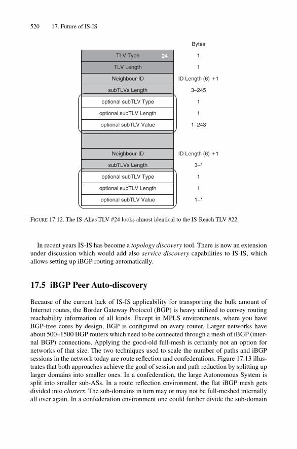
520 17. Future of IS-IS
In recent years IS-IS has become a topology discovery tool. There is now an extensionunder discussion which would add also service discovery capabilities to IS-IS, whichallows setting up iBGP routing automatically.
17.5 iBGP Peer Auto-discovery
Because of the current lack of IS-IS applicability for transporting the bulk amount ofInternet routes, the Border Gateway Protocol (BGP) is heavy utilized to convey routingreachability information of all kinds. Except in MPLS environments, where you haveBGP-free cores by design, BGP is configured on every router. Larger networks haveabout 500–1500 BGP routers which need to be connected through a mesh of iBGP (inter-nal BGP) connections. Applying the good-old full-mesh is certainly not an option fornetworks of that size. The two techniques used to scale the number of paths and iBGPsessions in the network today are route reflection and confederations. Figure 17.13 illus-trates that both approaches achieve the goal of session and path reduction by splitting uplarger domains into smaller ones. In a confederation, the large Autonomous System issplit into smaller sub-ASs. In a route reflection environment, the flat iBGP mesh getsdivided into clusters. The sub-domains in turn may or may not be full-meshed internallyall over again. In a confederation environment one could further divide the sub-domain
TLV Type
TLV Length
Neighbour-ID
optional subTLV Value
24
Bytes
1
1
ID Length (6) �1
3–245
1
1
1–243
subTLVs Length
optional subTLV Type
optional subTLV Length
Neighbour-ID
optional subTLV Value
ID Length (6) �1
3–*
1
1
1–*
subTLVs Length
optional subTLV Type
optional subTLV Length
FIGURE 17.12. The IS-Alias TLV #24 looks almost identical to the IS-Reach TLV #22

Fu
ll m
esh
iBG
P
Ro
ute
Ref
lect
ion
Clu
ster
0.0.
0.1
Clu
ster
0.0.
0.3
Clu
ster
0.0.
0.2
To
p L
evel
Fu
ll M
esh
Co
nfe
der
atio
n
sub
AS
650
01
sub
AS
650
02
sub
AS
650
03 R
RR
R
RR
RR
FIG
UR
E17
.13.
Bot
h co
nfed
erat
ions
and
rout
e re
flect
ors
redu
ce th
e ov
eral
l num
ber o
f pat
hs in
the
netw
ork
by s
plitt
ing
the
big
rout
ing
mes
h in
to s
mal
ler
dom
ains
521

522 17. Future of IS-IS
into “sub-sub-domains” by introducing a level of route reflection in the sub-AS. That wouldalso work in a Route Reflection environment. A cluster of routers can serve another clus-ter of routers.
There is no need (or desire) here to further elaborate on the different methods of iBGPscaling techniques. However, it is now obvious that the resulting iBGP mesh is a lot morecomplicated to describe once you are using one of the two iBGP scaling tools. Furthermore,maintaining the iBGP mesh, which means verifying that all routers are homed to theright cluster and are all producing consistent routing decisions, is a daunting task for theoperation teams at all service providers.
The Internet Draft draft-raszuk-isis-bgp-peer-discovery describes a method that RouteReflectors and Confederation sub-ASBRs (Autonomous System Border Routers) canuse to advertise their capabilities to terminate iBGP sessions. The magic carpet to trans-port those announcements is a TLV, the number of which has not yet been determined byIANA. This is illustrated in Figure 17.14.
The TLV is part of the LSP that is flooded inside an IS-IS level. Upon receipt of sucha TLV the receiving router checks to see if it wants to connect to that router. Figure 17.15shows an example of how iBGP provisioning times can be radically reduced.
All Level 2 routers are part of the full mesh and advertise that they want to be full-meshspeakers in the IS-IS Level 2. Once that information is received by any Level 2 router,those routers try to connect to and bring up the BGP full mesh. In Level 1 the situation isa bit different. The L1L2 router advertises that it is a route reflector and so all the Level1 routers connect to the proposed route reflectors.
TLV Type
TLV Length
IANA
Bytes
1
1
BGP Identifier 4
Frag 2
Checksum 2
Flooding Reserved 2
Autonomous System(s) orconfederation sub-AS(s) sub-TLV
variable
F D
BGP Reserved
IPv4/IPv6 Peering Addresssub-TLV
AFI/SAFI for mesh topologiessub-TLV
AFI/SAFI for reflection topologiessub-TLV
variable
variable
variable
FIGURE 17.14. The BGP discovery TLV empowers an IS-IS speaker to automatically provision theiBGP distribution mesh

Capability Announcement 523
The authors of the draft keep emphasizing that this method should not replace the cur-rently prevailing method of manual configuration, but rather should be taken in baby steps.Auto iBGP Peer discovery is seen as a complementary technique to foster a softer transi-tion for fully automated peer discovery. Especially for larger networks, this seems to bea promising technique for migration from an overly cautious route reflection design to afull-mesh BGP setup producing good routes with diverse paths.
17.6 Capability Announcement
The IS-IS working group has been busy in the last 5 years producing a lot of extensionsto the base protocol. All of the extensions are documented as Internet drafts which ultim-ately get published as informational RFCs, not normative references. There is nowincreasing concern that the extensions to IS-IS are getting to be a pick-and-choose
Route Reflection
Cluster0.0.0.1
IS-IS Level 1
Cluster0.0.0.3
IS-IS Level 1Cluster0.0.0.2
IS-IS Level 1
TopLevelFull Mesh
IS-IS Level 2
RRRR
RRRR
FIGURE 17.15. The Level 1 routers are looking for route reflector announcements, where the Level 2routers are looking for full-mesh partner announcements

self-service shop for vendors. That is, certain extensions are implemented and certainothers are not. As shown in Chapter 15, “Troubleshooting”, there are failure patterns thatresulted from the router’s ability to process and understand a TLV correctly. For the trou-bleshooting process it becomes important to assess the router’s capabilities in that regard.How does the network operations engineer know what TLVs a troublemaking routerunderstands? Logging into that router, checking the router operating system version,going to the vendor’s website, and looking what TLVs can be processed is often an awk-ward and cumbersome way of getting capability information. Figure 17.16 shows thestructure of a TLV that could convey the information that a certain router can process.
This TLV is, like the Hostname TLV, a purely informational or convenience TLV thatonly addresses informational issues. There are no routing or traffic engineering decisionsaffected by the existence or non-existence of a bit in this TLV. It is purely a tool for giv-ing the NOC engineer help supporting the network. The Capability TLV #242 triggeredan interesting question: how much information should a routing protocol really carry?This a good question especially when there is non-routing and non-topology data involved.
17.7 Conclusion
The further extension of the IS-IS protocol is not going to stop anytime soon. Additionalfunctionality is required by many service providers and will continue to force evolutionof the protocol. However, there is some recent discomfort caused by this functional growth.Many network engineers share the view that virtually all routing protocols are beingoverloaded across the board. IS-IS is no exception to that concern. Functionalities likeHostname Resolution (TLV #137), iBGP router auto-discovery and Capability Announce-ment are utilizing the flooding sub-system of IS-IS to get non-IP routing-related dataacross the network. As discussed in Chapter 13, “IS-IS Extensions”, there is always atradeoff between new functionality and stability because software needs to go through a
524 17. Future of IS-IS
Bit
0–34567891011121314–31
TLV Type
TLV Length
242
Bytes
1
1
Reserved 3
total subTLV length 1
subTLV Type 1
subTLV length 1
Capability Vector 4
F Reserved 1
other optional subTLVs variable (N * 4)
T D
1
Capability Vector
Capability Name
ReservedIS-IS graceful restart capableIS-IS and BGP blackhole avoidance capableIS-IS wide metric processing capableIS-IS short metric processing capableIS-IS hmac-md5 authentication capableIS-IS Traffic Engineering supportIS-IS point-to-point over LANIS-IS Path Computation Server discoveryM-ISIS capableIS-IS IPv6 capableFor future assignments
FIGURE 17.16. The important content of TLV 242 is the Capability Vector Sub-TLV #1 which con-tains the one set bit per supported capability

maturity cycle. IS-IS is a bit special in that respect because IS-IS represents a very criti-cal part of the routing sub-system in a service provider network. If you overload BGPwith a new functionality, then most likely bugs will stay within the given boundaries ofthat sub-system. For example, a bug in the MPLS-VPN code is unlikely to impact publicBGP routing on the Internet. However, whenever you start to add new functionality to IS-IS,then you need to touch the LSP origination code, which is a much more dangerous place toplay. The impact here may be much more catastrophic, as virtually all sub-systems in anetwork rely on a proper working IGP. If the IGP fails then everything else starts to fail:things like bogus TE databases, torn-down RSVP sessions, LDP sessions to a collapsingBGP mesh could easily result. So one needs to ask the question: How much “overloading”of the IGP is really useful? Perhaps the wise answer is to take a look at the risk versus thereward of certain functionality. In IS-IS, the risk of destabilizing things is very high and very real, so one needs to make a solid case for adding functionality to solve a realengineering problem.
While it makes perfect sense to add new functionality in order to solve engineeringproblems like producing new services for BGP, or consolidating infrastructure (as in theG-MPLS case), it is somewhat dangerous to jeopardize the stability of the current IS-IScode base for convenience or administrative functions like capability announcements. It is the authors’ opinion that the IS-IS community should stay away from the temptationto enhance such fragile portions of the network with functionality that yields, at best, aquestionable or intangible gain.
What is right or wrong, and what functionalities will finally be deployed in our net-works, will always remain an open issue.
Walter would like to close this chapter with something called Walter’s First Rule ofNetworking, formulated after more than 35 years of networking experience:
When the new stuff is more risky to deploy, and more complex than the workaround – use theworkaround!
Hannes would like to close this last chapter with an insight from Pedro Marquez, a wellrespected protocol engineer who was at Cisco Systems and now works for JuniperNetworks. Pedro was concerned about the IP-only zealots – in response he used to say:
No one is paying vendors for not doing things – however we need to still keep some commonsense!
Conclusion 525

Index
527
AAL-5 399–400Active configuration 68Addresses
In ISIS 96IP 96–98IP model 98–100IP to OSI 102–103NET 92–93, 100OSI 100–104
Example 104Private, in ISIS 103–104
Adjacency 85Failure scenario 124–129Scaling for LANs 183–186Table 28
Administrative distance 145Administrative tagging 324, 339Aggregated routes 45–46AFI 103APS, and adjacency failure 124–126Architecture, see Router architectureArea Address TLV #1 241Areas 83–84
IDs 92, 101, 103–104OSPF v. ISIS 85Merging 92Migration 90–92Multiple IDs 91Re-numbering 92Splitting 92
ASICs 16, 32ATM
AAL-5 399–400And MPLS 402–404Flooding LSPs on 166–67Overhead for TCP/IP 399Overlay networks 395–400
Atomic-module kernel 25ATT bit 89, 143Attribute typeblock 144, 155
AuthenticationImplementation 356–358Interoperability 364IOS 358IP Authentication TLV #133 317–318Of routing information 351On p2p links 355Suppression of 361TLV #10 211, 351Use recommended 499–500Weaknesses in ISIS 353
Auto-bandwidth for ISIS 320Auto-calculation of metric 319Auto-completion 39
BCD encoding of IP address 102Bellman-Ford 2, 4BFD 137BGP
And forwarding tables 276–279And ISIS 274–276, 481–482Auto-peering 522–523And the IGP 160–161Discovery TLV 522Peer discovery 522–523Recommendations for ISIS 485Route reflectors 162, 522Route resolution 273Route selection 274Scaling 479
Bidirectional fault detection 137–139Bit bucket 45Bits
ATT 89, 143EXP 404I/E 302–303, 312Overload see overload bitUp/down 331
Broadcast interface 80Buffer Size TLV #14 244
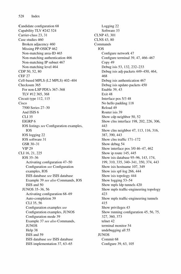
Candidate configuration 68Capability TLV #242 524Carrier-class 23, 31Case studies 460
Broken adjacency 460Missing PP-OSICP 462Non-matching area-ID 465Non-matching authentication 466Non-matching IP subnet 467Non-matching level 464
CDP 50, 52, 80CEF 27Cell-based MPLS (L2 MPLS) 402–404Checksum 365
For non-LSP PDUs 367–368TLV #12 365, 368
Circuit type 112, 115Cisco
7500 Series 27–30And ISIS 6CLI 35EIGRP 6IOS listings see Configuration examples,
IOSIOS logging 22IOS software 31GSR 30–31VIP 29
CLI 16, 21, 225IOS 35–36
Activating configuration 47–50Configuration see Configurationexamples, IOSISIS database see ISIS databaseExample 39 see also Commands, IOSISIS and 50
JUNOS 35–36, 56Activating configuration 68–69Auto-completion 39CLI 35, 56Configuration examples seeConfiguration examples, JUNOSConfiguration mode 39Example 37 see also Commands,JUNOSHelp 38ISIS and 59ISIS database see ISIS databaseISIS implementation 37, 63–65
Logging 22Software 33
CLNP 43, 301CLNS 43, 80Commands
IOSConfigure network 47Configure terminal 39, 47, 466–467Copy 49Debug isis 53, 132, 232–233Debug isis adj-packets 449–450, 464,468Debug isis authentication 467Debug isis update-packets 450Enable 39, 43Exit 48Interface pos 5/3 48No hello padding 118Reload 49Router isis 39Show cdp neighbor 50, 52Show clns interface 198, 202, 226, 306,443Show clns neighbor 47, 113, 116, 316,387, 390, 443Show clns traffic 171–172Show debug 54Show interface pos 3/0 46–47, 462Show ip route 145, 445Show isis database 95–96, 143, 174,199, 310, 335, 340–341, 350, 374, 443Show isis hostname 107, 349Show isis spf-log 266, 444Show isis topology 444Show logging 53–54Show mpls ldp tunnels 420Show mpls traffic-engineering topology423Show mpls traffic-engineering tunnels415Show privileges 43Show running configuration 45, 56, 75,327, 360, 373telnet 42terminal monitor 54undebugging all 55
JUNOSCommit 68Configure 39, 63, 105
528 Index

Delete 67Edit 65Exit 65Monitor 72, 451, 456Request 58Rollback 68Set interface 67Show 66, 70Show bfd session 139Show cli authorization 57Show interfaces 62, 225–226, 463Show isis 38Show isis adjacency 105, 106, 114, 115,315, 345, 385, 391, 446Show isis database 37, 96, 143,157–158, 174, 194, 311, 337, 342–343,350, 375, 446, 470, 471, 473Show isis hostname 107, 349Show isis interface 60, 137, 197, 201,210, 306, 445Show isis route 145Show isis spf log 266, 386, 447Show isis spf results 448Show isis statistics 172, 220Show ldp neighbor 421Show log 132, 243, 464Show log isis-trace 71Show mpls lsp ingress 416Show route 448Show route protocol isis 146Show route table inet6.0 protocol isis375Show ted database 423Show | compare 463–464, 467–468Start shell 457 telnet 57top 65, 66
Compatibility announcements 523–524Conclusions see SummariesConfiguration examples
IOSAdjacency scenario 461–462Administrative tagging 339, 341Advertise passive only 477Authorization 359Basic 40Changing configuration 47–49CSNP interval 209ERO (MPLS) 412–413
Forwarding adjacency 434Hello interval 136Host names 346–347IPv6 373ISIS (complete example) 452LDP 418LDP tunnels 431LSP bandwidth limit 177LSP generation interval 179LSP parameters 150LSP transmit interval 176Mesh group 170Mesh group blocking 169Multi-topology 386Multiple IP addresses per interface 314No hello padding 118NETs 104Overload bit (dynamic) 163Overload bit (static) 161Passive ISIS 306Policy 75PRC interval 268Pseudonode suppression 198Redistribute RIP into ISIS 310Retransmission interval 181Retransmission throttle 182Route leaking L1 to L2 338Route leaking L2 to L1 334–335RRO (MPLS) 415SPF compatibility 264SPF hold down 261Static ISIS metric 322Tagging 339, 341TE tunnels 425Three-way handshake 131
JUNOSActivating configuration 68–70Adjacency scenario 461Administrative tagging 342–342Advertise passive policy 477–478Authorization 355, 361–362Authorization suppression 363–365Area merging 93Area renumbering 95Area splicing 94Basic 39BFD liveliness 138Checksum 366Configuration mode 63–65
Index 529

Configuration examples (cont'd)CSNP interval 209ERO (MPLS) 414Export static to ISIS 471–472Flags (traceoptions) 451, 464Forwarding adjacencies 434Hello interval 136Host names 346–347IGP updates 437IPv6 374–375ISIS (basic example) 66–68ISIS (complete example) 454LDP 431LDP tunnels 431LSP parameters 152LSP transmit interval 177Mesh group 170Mesh group blocking 169Multi-topology 383NETs 105Overload bit (dynamic) 163Overload bit (static) 162Passive ISIS 305Policy see routing policy examplesPrefix export limit 474Pseudonode suppression 197Reference bandwidth 320RIP export policy 312Route leaking L1 to L2 338Route leaking L2 to L1 336Routing policy (advertise passive) 477–478Routing policy (basic) 76–77Routing policy (export static to ISIS)471–472SPF compatibility 264SPF delay 262Static ISIS metric 323Suppress authorization 363–365Suppress new-style TLVs 328Tagging 342–343TE tunnels 425–426Traceoptions (ISIS flags) 451, 464
Configuration mode 36, 39COS 28, 156
MPLS 404RSVP 408
Content checking, on TLV 298CPU load, SPF 264–265CR-LDP 408
Crankback 428CSNP 208, 218, 220, 236, 239–240
Authorization 365Header 211PDU 211–213Synchronization 214
CSPF 422Calculation 428
Datagram 12DCC 103Debug isis 53, 132, 232–233Debug isis adj-packets 449–450, 464, 468 Debug isis authentication 467Debug isis update-packets 450Debugging 40, 52
Adjacencies 132Authentication 359–360, 363Commands
Debug isis (IOS) 53, 132, 232–233Debug isis adj-packets (IOS) 449–450,464, 468Debug isis authentication (IOS) 467Debug isis update-packets (IOS) 450Monitor (JUNOS) 451, 456Show | compare (JUNOS) 463–464,467–468Show log (JUNOS) 464
Bogus IP address 316–317ISIS
In IOS 53In JUNOS 70
MTU size 232–233DEC 2, 31DECNet
Phase IV 2Phase V 2, 4
DiffServ 14 Dijkstra 2, 248Distributed database 141–142Distribution of prefixes 329–331Direct translation of IP address 102–103DIS 113, 188 (see also DR)
And psuedonodes 183Election 173, 199ID (JUNOS) 201–202Pre-emption 200Priority 199–200Redundancy 202
530 Index

DR 113, 183 (see also DIS)In OSPF 203
DraftsDraft-ietf-isis-igp-p2p-over-lan-03 (P2P
over LAN) 196Draft-ietf-isis-traffic-05 (G-MPLS)
513Draft-ietf-isis-wg-multi-topology
(multi-topology) 324Draft-katz-ward-bfd-v4v6-1hop-00 (BFD)
137Draft-martin-neal-policy-isis-admin-tags
(admin tags) 324Draft-raszuk-isis-bgp-peer-discovery (BGP
peer discovery) 522DNS 106, 347Drop-dead timer 112Dynamic hostname 345Dynamic Hostname TLV #137 347
E.164 103EBGP see BGPEIGRP 6Emacs 40Encapsulation 81End system 12, 13Equal-cost paths 399ES-IS 100Ethereal 232, 457–458Ethernet encapsulation 81Examples see Configuration examples EXP bits 404Explicit route object (ERO) 412–422Extended IP Reachability TLV #135 318,
324–325Extended IS Reachability TLV #22 293,
318Extensibility 5, 289–291
Fabric 17, 30, 32Failure scenarios, adjacency
APS 124–126Parallel links 126–127
Fault detection 489–490FIB 18, 30
And CEF 27And RIB 19–21Juniper 32
Filter-based forwarding 14
Filters, route see Routing policyFinite state machine 109, 133Flag-day migration 376Flags
IOS 53JUNOS 70
Flat forwarding table 276–277
Fletcher checksum 366–267Flooding 164–165
In OSPF 329–330Issues 165–168, 395, 479Meltdowns due to 296Mesh-groups and 168
Flow control 159–160Of LSAs 175In ISIS 436
Forwarding 15adjacencies 433In LDP 418plane 16, 18–19tables 17, 276–279
FPCs 32, 62FPGA 16Fragment 0 241
Wander 242Space 243
Fragment-ID 154, 191Fragmentation 223
Extended 518–520IP 228–229For ISIS 230–232LSPs 485–488
FreeBSD 33, 57, 61Full SPF run 258–267
Generation interval of LSPs 178
Graceful restart 388–389Use recommended 501
G-MPLS 504ISIS extensions for 513–514Issues 505–506Overlay 506–509Peer 509–512Summary 514–515
GSR 30–31GUI 35
Index 531

Handshaking 109, 1662way (P2P) 119, 123–124, 1333way 119–122, 134, 179
P2P 128–129Problems with 124–127
Header, ISIS message 110Hello messages 109–110, 124–128, 135–136,
206, 234Capabilities 284–285LAN 111, 183–184P2P 114Scheduling 185Suppressing 304–305Targeted 430
Help for commands 38Hidden routes 76Hierarchical forwarding table 278–279HMAC-MD5 351, 356, 368
Use recommended 499–500Hold down timer 134
SPF 258Holding time 112, 115, 143Hop-by-hop routing 14Hostname, dynamic 345Hosts 13
iBGP see BGPICD 103IDRP Information #131 313–314I/E bit 302–303, 312IETF, ISIS WG 6, 503–504IGP, and BGP 160–161IGP metrics see MetricsIncremental SPF run 270–272Interface address, ISO 100–104
Example 104Interface names 44
IOS 46JUNOS 60Virtual
In JUNOS 80Loopback 44–45, 99–100, 105, 339, 432,477, 490Null 45
Internal tracking 137Internet drafts see draftsInterprocess communications 24–26Interworking issues
Metrics 327
IPv6 376–378IOS 35–36, see also Cisco
Activating configuration 47–50Configuration see Configuration examples,
IOSInterface names 46ISIS database see ISIS databaseExample 39, see also Commands, IOSISIS and 50
IP address 17Model 98–100Prefix 17, 96–97
IP Authentication TLV #133 317–318IP External Reachability TLV #130 309, 313IP Interface Address TLV #132 131, 298, 314IP Internal Reachability TLV #128 304IPv6 370–372
Interoperability 376–378IPv6 Reachability TLV #236 372IS Alias TLV #24 520IS Neighbors TLV #6 122, 134IS Reachability TLV #2 109, 186, 301–302ISIS
8-level 515–516Addresses 96, 100–104
Area-ID 101Examples 104IP addresses 102–103NSEL 101Private 103–104System-ID 101–102
Areas 83–84,IDs 92, 101, 103–104OSPF v. ISIS 85Merging 92Migration 90–92Multiple IDs 91Re-numbering 92Splitting 92
ATT bit 89, 143Authentication
Implementation 356–358Interoperability 364IOS 358IP Authentication TLV #133 317–318On p2p links 355Suppression of 361TLV #10 211, 351Use recommended 499–500
532 Index

Weaknesses in ISIS 353BGP and 274–276, 481–482Cisco 6Common header 110Configuration
Basic 66–68IOS 451JUNOS 452
Configuration examples see Configurationexamples
Database 142–143, 433 see also Link-statedatabase
Defined 1DIS 113, 188 (see also DR)
And psuedonodes 183Election 173, 199ID (JUNOS) 201–202Pre-emption 200Priority 199–200Redundancy 202
Distribution of prefixes 329–331Encapsulation
802.3 81SNAP 231–232
Extended fragmentation 518–520Extensibility 5, 289–291Extensions 345Flooding and TED 436Full Internet routes 469Future of 503G-MPLS extensions 513–518Graceful restart 388–389IETF and 6Interface 80Intergration with IP 5IOS commands for see Commands, IOSIP addresses and 102–103IPv6 370JUNOS commands for see Commands,
JUNOSLDP and 421Levels
8-level ISIS 513–518Defined 85L1 85–87, 112, 142, 144, 155, 240, 331L1L2 85–87, 112, 115, 156, 159, 240,331, 339L2 85–87, 112, 143–144, 146, 155, 240,331
Recommendations 493–494Liveliness 135–136LSDB 141–142, 433 see also Link-state
databaseLSPs see LSPsMAC addresses and 80Messages
Common header 110Hello 109–110LAN hello 111P2P hello 114
Metrics 14, 193, 267, 294–295 301Auto-bandwidth 320Auto-calculation of 319–320And traffic engineering 393Interworking issues 327Example 250–253New-style 318Old-style 301–302, 304–205, 327Static 320–322Wide 304, 318, 408
MTU size 82, 230–232Checking 116Issues 230–232
Multi-topology 379Neighbor liveliness detection 135–136NETs 92–93, 100On NSFNet 3–4Origin of 2–4OSI-RM and 79–80Overload bit 154, 156–157, 159
Application 159–160Fragments and 244Setting 161–163Use recommended 499
Padding 116, 234–235Private addresses 103–104Pseudonode 153, 183, 186–187, 301
And SPF calculation 254–256Representation 188Suppression of (P2P) 196System-ID selection 191–193
PSNP 208, 218, 236–238And authorization 365
Purging LSPs 172–175Expiration of 174
Route leaking, ISIS 87–90Level 1 to Level 2 337Level 2 to Level 1 331–334
Index 533

ISIS (cont'd)Route resolution 247, 273–276Routing policy 55, 73, 76–77, 310, 312,
336, 471–472, 477–478 see also Routeleaking
Sample networkAddresses 8Topology 7
Scaling 475LANs 183–186Levels and 494–497
Show commands see CommandsSNAP encapsulation 231–232SPF calculations 94, 126, 144, 156, 208,
241, 247Stress 479
CPU and memory 483Flooding 479Forwarding state change 481SPF 480
Synchronizing database see Link-statedatabase, synchronization
TLVs see TLVsTroubleshooting 439, 460 see also
Troubleshooting, commandsBroken adjacency 460Missing PP-OSICP 462Non-matching area-ID 465Non-matching authentication 466Non-matching IP subnet 467Non-matching level 464
ISO 10589Basics 1, 3, 79, 178–179, 181Flooding 296Hellos and LSPs 220IPv6-IPv4 376Jitter 185–186MTU size 234Oddities 102, 116, 131, 156, 218
New-style metrics 318 Pseudonode priority 257TLV use 345
Reachability information 301ISPs 28, 102
Jitter, for timers 185Juniper
JNBI 77JUNOS
Activating configuration 68–69Auto-completion 39CLI 35, 56Configuration examples seeConfiguration examples, JUNOSConfiguration mode 39Example 37 see also Commands,JUNOSHelp 38ISIS and 59ISIS database see ISIS databaseISIS implementation 37, 63–65Logging 22Software 33
M-series 31T640 159
JUNOS see Juniper
Kernel 23–26Atomic-module 25
L1, L1L2, L2 see LevelsLabel request object (LRO) 412Label stacking 404Labels, MPLS 402LAN-ID 106, 173, 200LANs
Scaling ISIS for 183–186Synchronization on 208
Layer 2 MPLS (cell-based MPLS) 402–404Layer 2 overlays 395–400Layer 3 MPLS (Packet-based MPLS)
404–408LDP 408, 417–418
And ISIS 427And RSVP-TE 428–430
Length check, on TLVs 296–297Levels, ISIS
Defined 85L1 85–87, 112, 142, 144, 155, 240, 331L1L2 85–87, 112, 115, 156, 159, 240, 331,
339L2 85–87, 112, 143–144, 146, 155, 240,
331Recommendations 493–494Scaling 494–497
Link-state database 37, 94, 142, 160And fragments 243Example 250–253
534 Index
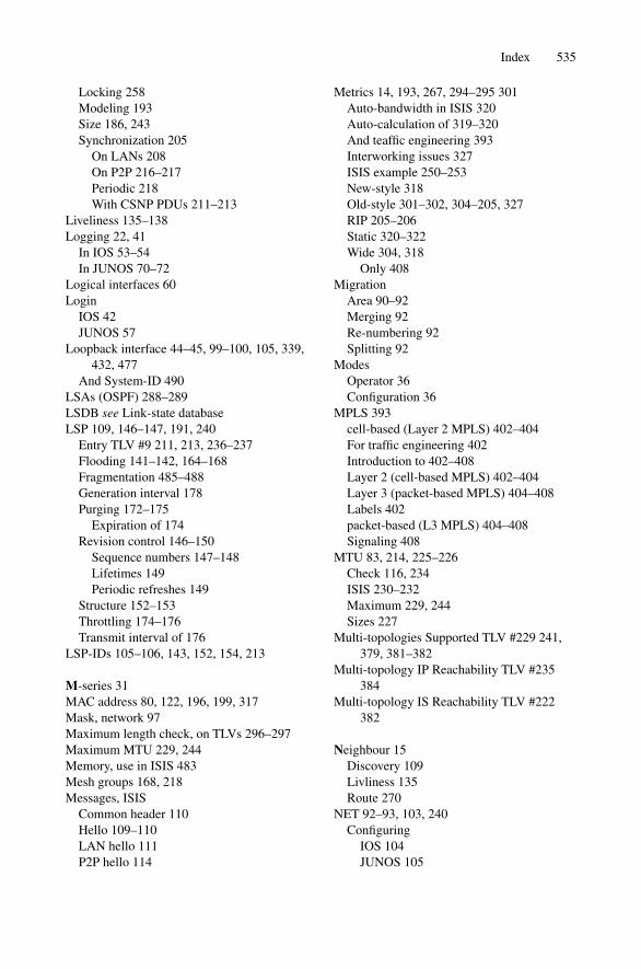
Locking 258Modeling 193Size 186, 243Synchronization 205
On LANs 208On P2P 216–217Periodic 218With CSNP PDUs 211–213
Liveliness 135–138Logging 22, 41
In IOS 53–54In JUNOS 70–72
Logical interfaces 60 Login
IOS 42JUNOS 57
Loopback interface 44–45, 99–100, 105, 339,432, 477
And System-ID 490LSAs (OSPF) 288–289LSDB see Link-state databaseLSP 109, 146–147, 191, 240
Entry TLV #9 211, 213, 236–237Flooding 141–142, 164–168Fragmentation 485–488Generation interval 178Purging 172–175
Expiration of 174Revision control 146–150
Sequence numbers 147–148Lifetimes 149Periodic refreshes 149
Structure 152–153Throttling 174–176Transmit interval of 176
LSP-IDs 105–106, 143, 152, 154, 213
M-series 31MAC address 80, 122, 196, 199, 317Mask, network 97Maximum length check, on TLVs 296–297Maximum MTU 229, 244Memory, use in ISIS 483Mesh groups 168, 218Messages, ISIS
Common header 110Hello 109–110LAN hello 111P2P hello 114
Metrics 14, 193, 267, 294–295 301Auto-bandwidth in ISIS 320Auto-calculation of 319–320And teaffic engineering 393Interworking issues 327ISIS example 250–253New-style 318Old-style 301–302, 304–205, 327RIP 205–206Static 320–322Wide 304, 318
Only 408Migration
Area 90–92Merging 92Re-numbering 92Splitting 92
ModesOperator 36Configuration 36
MPLS 393cell-based (Layer 2 MPLS) 402–404For traffic engineering 402Introduction to 402–408Layer 2 (cell-based MPLS) 402–404Layer 3 (packet-based MPLS) 404–408Labels 402packet-based (L3 MPLS) 404–408Signaling 408
MTU 83, 214, 225–226Check 116, 234ISIS 230–232Maximum 229, 244Sizes 227
Multi-topologies Supported TLV #229 241,379, 381–382
Multi-topology IP Reachability TLV #235384
Multi-topology IS Reachability TLV #222382
Neighbour 15Discovery 109Livliness 135Route 270
NET 92–93, 103, 240Configuring
IOS 104JUNOS 105
Index 535

NET (cont'd)Examples 104Selector 101
NetworkAnalysis 455–456Design 475Mask 97Recommendations 484
New-style metrics 318, 324–325, 327Next-hop 14, 17, 98, 483NLRI 285NLPID 307, 376NLSP 5NLSRP 80Node ID 191, 194, 200Non-extensible routing protocol 283–285NSEL 101NSFNet 3
Meltdown 296Null interface 44NVRAM 35, 47
Objects, RSVP-TE 410Old-style metrics 301–302, 304–205, 327Old-style TLVs
IP reachability 304–305IS reachability 301–302
Opaque LSAs 289Operator mode 36–39OS see router OSOSI-RM 1, 52, 61, 76, 124, 223–225OSPF 4
Areas 85, 89AS numbers 104DR 113Extending 285–289Hello message 286Issues 87LSA type field 288Prefix distribution 329Reference bandwidth 319Routing leaking 88
Overlay network 395–397Overload bit 154, 156–157, 159
Application 159–160Fragments and 244Setting 161–163Use recommended 499
P2P 80, 218Adjacency State TLV #240 128, 134Authorization for 355Hello message 114Over LAN 196
Packet-based MPLS (L3 MPLS) 404–408Padding TLV #8 116, 234–235Partial SPF run 267–268Partition repair 155Path MTU discovery 229–230PDU
CSNP 208Length 115PSNP 208
Penultimate router 408Permanent interface 60PFE 31–32, 61Physical interface 60PICs 32, 62Policy routing 14PRC 268Pre-emption of DIS 200Prefix
Distribution 329–331Insertion 247, 276–278IP address 97
Priority, DIS 199–200Private addresses in ISIS 103–104Privilege level 58Prompt 36, 39, 63Proteon 36Protocols Supported TLV #129 307, 370–371,
376Pseudonode 153, 183, 186–187, 301
And SPF calculation 254–256Representation 188Suppression of (P2P) 196System-ID selection 191–193
PSNP 208, 218, 236–238And authorization 365
Purging LSPs 172–175Expiration of 174
QOS see COS
Reachability information 301Recommendations
Authentication 499–500BGP for ISIS 485
536 Index
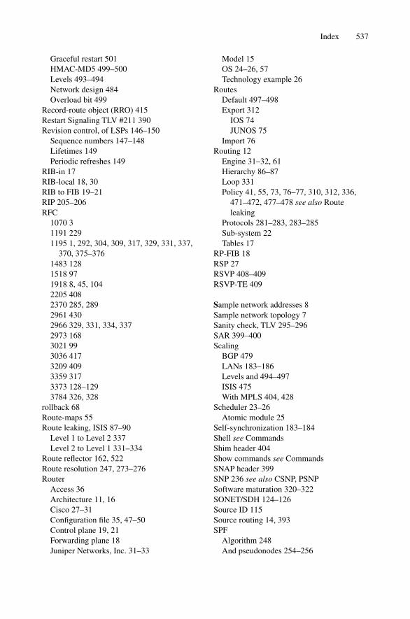
Graceful restart 501HMAC-MD5 499–500Levels 493–494Network design 484Overload bit 499
Record-route object (RRO) 415Restart Signaling TLV #211 390Revision control, of LSPs 146–150
Sequence numbers 147–148Lifetimes 149Periodic refreshes 149
RIB-in 17RIB-local 18, 30RIB to FIB 19–21RIP 205–206RFC
1070 31191 2291195 1, 292, 304, 309, 317, 329, 331, 337,
370, 375–3761483 1281518 971918 8, 45, 1042205 4082370 285, 2892961 4302966 329, 331, 334, 3372973 1683021 993036 4173209 4093359 3173373 128–1293784 326, 328
rollback 68Route-maps 55Route leaking, ISIS 87–90
Level 1 to Level 2 337Level 2 to Level 1 331–334
Route reflector 162, 522Route resolution 247, 273–276Router
Access 36Architecture 11, 16Cisco 27–31Configuration file 35, 47–50Control plane 19, 21Forwarding plane 18Juniper Networks, Inc. 31–33
Model 15OS 24–26, 57Technology example 26
RoutesDefault 497–498Export 312
IOS 74JUNOS 75
Import 76Routing 12
Engine 31–32, 61Hierarchy 86–87Loop 331Policy 41, 55, 73, 76–77, 310, 312, 336,
471–472, 477–478 see also Routeleaking
Protocols 281–283, 283–285Sub-system 22Tables 17
RP-FIB 18RSP 27RSVP 408–409RSVP-TE 409
Sample network addresses 8Sample network topology 7Sanity check, TLV 295–296SAR 399–400Scaling
BGP 479LANs 183–186Levels and 494–497ISIS 475With MPLS 404, 428
Scheduler 23–26Atomic module 25
Self-synchronization 183–184Shell see CommandsShim header 404Show commands see CommandsSNAP header 399SNP 236 see also CSNP, PSNPSoftware maturation 320–322SONET/SDH 124–126Source ID 115Source routing 14, 393SPF
Algorithm 248And pseudonodes 254–256
Index 537

SPF (cont'd)Calculation 83, 94, 126, 144–145, 147,
156, 208, 241, 247CPU load 264–265, 480–481Defined 2Diversity 257Example 249–253Incremental 270–272Partial run 267–268Runtime 266Self-protection 259–261Sorting 303–304
Start shell see CommandsStatic LSPs 408Static metrics 320–322Stress 479
CPU and memory 483Flooding 479Forwarding state change 481SPF 480
Sub-TLVs 281, 293–295And traffic engineering 427Minimum and maximum length 298Overrun checking 297–298Shading 8
SummariesAdjacency 140CLI 77–78CSNP (and PSNPs) 222Design recommendations 501–502DIS 203–204Extensions to ISIS 387, 391Fragmentation 245Future 524–525ISIS basics 107–108LSP basics 182MPLS signaling 422PSNP (and CSNPs) 222Route leaking 344Router architecture 33–34SPF runs 279TLVs 299Traffic engineering 437Troubleshooting 474
Switching 17, 28VIP 29
Synchronization 205LSPs 214On LAN 208
On P2P 216Self 183–184
System-ID 101–102, 112, 240, 301And pseudnode 191–193Duplicate 175Loopback 490
TablesAdjacency 28CEF 27Forwarding 17RIB-IN 17RIB-local (RIB) 18, 30RIB to FIB 19–21RP-FIB (FIB) 18, 30, 32Routing 17
Tagging 339Targeted hellos 430Tcpdump listings
Adjacency TLV 130Authorization 352–253, 356, 370BFD 138BGP next-hop 273Checksum 366, 370CSNP 239DIS election 200–201DIS purge 201DIS redundancy 203External reachability TLV 293Full TE extensions 488Hello timer 136Hostname 348Ideal LSP 484–485IP external TLV 310IPv6 371, 373IS neighbor TLV 123Jitter (of timers) 185–186JUNOS interface 73Loopback/system-ID mapping 491LSP 154–155, 236LSP interval timer 178MTU 232Multi-topology 381–382Multiple IP interface addresses 315New-style metrics 324Padding TLV 117, 118, 235Protocols supported TLV 308–309Pseudonode 190–191Pseudonode suppression 196–197
538 Index

PSNP 238Graceful restart 390RSVP-TE 410, 424, 426TE sub-TLVs 435
TDP (Cisco) 418TE Router ID TLV #134 427TED 422, 428Text authorization 351Throttling LSPs 174–176Timers
Adjusting 492Drop dead 112, 136Hello 136–137Hold down 134
For SPF 258Holding 112Jitter for 185
TLVContent pattern checking 298Discrete length 298Encoding 291, 293For extensibility 281Format 289–291Lost of 292Minimum-maximum length 297Sanity checking 295–296Shading 9Sub-TLV 293–295 see also Sub-TLVType
Area Address #1 241Authentication #10 211, 351BGP Discovery #IANA 522Buffer Size #14 244Capability #242 524Checksum #12 365, 368Dynamic Hostname #137 347Extended IP Reachability #135 318,324–325Extended IS Reachability #22 293, 318IDRP Information #131 313–314IP Authentication #133 317–318IP External Reachability #130 309, 313IP Interface Address #132 131, 298, 314IP Internal Reachability #128 304IPv6 Reachability #236 372IS Alias #24 520IS Neighbors #6 122, 134IS Reachability #2 109, 186, 301–302LSP Entry #9 211, 213, 236–237
Multi-topologies Supported #229 241,379, 381–382Multi-topology IP Reachability #235384Multi-topology IS Reachability #222382P2P Adjacency State #240 128, 134Padding #8 116, 234Protocols Supported #129 307, 370–371,376Restart Signaling #211 390TE Router ID #134 427
Traceoptions 70, 132ISIS flags 451
Traffic engineering 328, 393Database (TED) 422, 428DiffServ aware 435–436Objects for 410Overlays 394–396With CSPF 422With MPLS 402With RSVP-TE 409–410
Transmit interval of LSPs 176Troubleshooting 41
Case studies 460Broken adjacency 460Missing PP-OSICP 462Non-matching area-ID 465Non-matching authentication 466Non-matching IP subnet 467Non-matching level 464
CDP 50Commands for 442
Debug isis (IOS) 53, 132, 232–233Debug isis adj-packets (IOS) 449–450,464, 468 Debug isis authentication (IOS) 467Debug isis update-packets (IOS) 450Monitor (JUNOS) 451, 456Show clns interface (IOS) 443Show clns neighbor (IOS) 47Show interface (JUNOS) 463Show interface pos 3/0 (IOS) 462Show ip route (IOS) 445Show isis adjacency (JUNOS) 446Show isis database (IOS) 443Show isis database (JUNOS) 446,470–471, 473Show isis interface (JUNOS) 445
Index 539
Troubleshooting (cont'd)Show isis spf log (JUNOS) 447Show isis spf results (JUNOS) 448Show isis spf-log (IOS) 444Show isis topology (IOS) 444Show log (JUNOS) 456, 464,447Show route (JUNOS) 448Start shell (JUNOS) 457–458
Configuration (JUNOS) 69ISIS 439, 441
Flow control 440Tools for 441
MPLS 422Network analyzer 455–456System-IDs 105–106
UNIX 33, 36, 57Un-numbered interface 100Up/down bit 331
URLsCisco documentation 56Dijkstra 248Ethereal 232FreeBSD 57
VIP 29, 32Virtual interfaces
In JUNOS 80Loopback 44–45, 99–100, 105, 339, 432,
477And SYS-ID 490
Null 45VPN 404
Wander 242Weight 145Wide-metrics 304, 318
Only 408
Y2K 149
540 Index

![3. Advanced Routing Mechanisms [10pt]PA191 - IS MUNI](https://static.fdokumen.com/doc/165x107/6332ce284d54c8e1f9079371/3-advanced-routing-mechanisms-10ptpa191-is-muni.jpg)