Sportsound® Rack SSR-300 - Daktronics
42
201 Daktronics Drive PO Box 5128 Brookings, SD 57006-5128 Tel: 1-800-DAKTRONICS (1-800-325-8766) Fax: 605-697-4746 www.daktronics.com/support Sportsound ® Rack SSR-300 Operation Manual DD2324779 Rev 4 – 24 August 2016
-
Upload
khangminh22 -
Category
Documents
-
view
3 -
download
0
Transcript of Sportsound® Rack SSR-300 - Daktronics

201 Daktronics Drive PO Box 5128 Brookings, SD 57006-5128Tel: 1-800-DAKTRONICS (1-800-325-8766) Fax: 605-697-4746www.daktronics.com/support
Sportsound® RackSSR-300
Operation Manual
DD2324779 Rev 4 – 24 August 2016

DD2324779P1340
Rev 4 – 24 August 2016
daktronics, inc.Copyright © 2012-2016All rights reserved. While every precaution has been taken in the preparation of this manual, the publisher assumes no responsibility for errors or omissions. No part of this book covered by the copyrights hereon may be reproduced or copied in any form or by any means – graphic, electronic, or mechanical, including photocopying, taping, or information storage, and retrieval systems – without written permission of the publisher.
Sportsound® is a registered trademark of Daktronics, Inc. All other trademarks are property of their respective companies.

Table of Contents i
Table of ContentsSection 1: Introduction .......................................................................................................................................... 1
1.1 Resources ............................................................................................................................................................... 11.2 Daktronics Nomenclature ................................................................................................................................... 2
Section 2: SSR-300 Components ......................................................................................................................... 32.1 Overview ............................................................................................................................................................... 32.2 Standard Equipment ............................................................................................................................................ 5
Audio Mixer ................................................................................................................................................... 5Professional CD/Media Player ................................................................................................................... 5Announcer’s Interface .................................................................................................................................. 5Laptop Interface ............................................................................................................................................ 6Wireless Microphone System ...................................................................................................................... 6Distribution Amplifier .................................................................................................................................. 7Feedback Reducer ......................................................................................................................................... 7ADA Hearing Assist System ....................................................................................................................... 7Wireless Personal Stereo Monitor System ................................................................................................. 7High Gain Antenna Kit ................................................................................................................................ 8Single-Muff Headset ..................................................................................................................................... 8Self-Powered Monitor Speaker ................................................................................................................... 8USB Audio Interface ..................................................................................................................................... 8
2.3 Signal Cables ......................................................................................................................................................... 8
Section 3: Setup & Operation ..............................................................................................................................113.1 Power & Signal Connections ............................................................................................................................ 113.2 Setup ..................................................................................................................................................................... 113.3 Powering ON ...................................................................................................................................................... 113.4 Powering Down .................................................................................................................................................. 123.5 Mixer Operation ................................................................................................................................................. 123.6 Wireless Mic System Operation ....................................................................................................................... 14
Wireless Receiver ........................................................................................................................................ 14Single Receiver ..................................................................................................................................... 14Network Receivers ............................................................................................................................... 14
Wireless Mic & Bodypack Operation ....................................................................................................... 153.7 Microphone Best Practices ................................................................................................................................ 163.8 Personal Monitor System Operation ............................................................................................................... 163.9 Hearing Assist System Operation .................................................................................................................... 18
Section 4: Maintenance & Troubleshooting ...................................................................................................... 194.1 Maintenance ........................................................................................................................................................ 194.2 Troubleshooting ................................................................................................................................................. 19
Section 5: Replacement Parts ............................................................................................................................ 215.1 SSR-300 Components ......................................................................................................................................... 21
Section 6: Daktronics Exchange and Repair & Return Programs .................................................................. 236.1 Exchange Program ............................................................................................................................................. 23
Before Contacting Daktronics ................................................................................................................... 236.2 Repair & Return Program ................................................................................................................................. 24
Shipping Address........................................................................................................................................ 246.3 Daktronics Warranty & Limitation of Liability ............................................................................................. 24
Appendix A: Reference Drawings .......................................................................................................................... 25
Appendix B: Supplementary Manuals ................................................................................................................... 33
Appendix C: Daktronics Warranty and Limitation of Liability ............................................................................. 35


Introduction 1
Section 1: IntroductionThis manual explains the operation of the Sportsound® Rack (SSR) 300. For additional information regarding the safety, installation, operation, or service of this system, refer to the telephone numbers listed in Section 6. This manual is not specific to a particular installation. Project-specific information takes precedence over any other general information found in this manual.
IMPORTANT SAFEGUARDS
• Read and understand all instructions before beginning the installation process.
• Do not drop the control equipment or allow it to get wet.
• Do not disassemble control equipment or electronic controls of the system; failure to follow this safeguard will make the warranty null and void.
• Always turn off and/or unplug the control equipment when it is not in use. This keeps equipment protected from power spikes and lightning.
• Never yank the power cord from the outlet. Grasp the plug and pull to disconnect.
• Do not let any power cord touch hot surfaces or hang over the edge of a table that would damage or cut the cord. Arrange the cord with care so that it will not be tripped over.
• Inspect control equipment for shipping damage such as rattles and dents, and verify that all equipment is included as itemized on the packing slip. Immediately report any problems to Daktronics; save all packing materials if exchange is necessary.
• Keep equipment covered when possible to protect from dust and debris.
1.1 ResourcesFigure 1 illustrates a Daktronics drawing label. The drawing number is located in the lower-right corner of a drawing. This manual refers to drawings by listing the last set of digits and the letter preceding them. In the example, the drawing would be referred to as Drawing D-1007804. All references to drawing numbers, appendices, figures, or other manuals are presented in bold typeface. Any drawings referenced in a particular section are listed at the beginning of it as shown below:
Reference Drawing:System Riser Diagram ................................................................................................. Drawing D-1007804
All drawings referenced in this manual are found in Appendix A.
Daktronics identifies manuals by the DD or ED number located on the cover page. For example, this manual would be referred to as DD2324779.
Daktronics has a searchable knowledgebase of common questions and troubleshooting tips: www.daktronics.com/support
Visit the Daktronics Support YouTube channel to learn how to properly operate Sportsound racks: www.youtube.com/DaktronicsSupport
Drawing Number
Figure 1: Drawing Label
2 Introduction
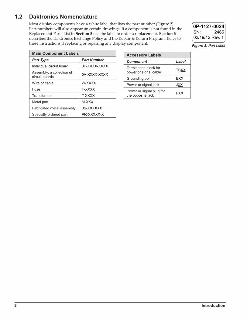
1.2 Daktronics NomenclatureMost display components have a white label that lists the part number (Figure 2). Part numbers will also appear on certain drawings. If a component is not found in the Replacement Parts List in Section 5 use the label to order a replacement. Section 6 describes the Daktronics Exchange Policy and the Repair & Return Program. Refer to these instructions if replacing or repairing any display component.
Main Component LabelsPart Type Part NumberIndividual circuit board 0P-XXXX-XXXX
Assembly; a collection of circuit boards 0A-XXXX-XXXX
Wire or cable W-XXXX
Fuse F-XXXX
Transformer T-XXXX
Metal part M-XXX
Fabricated metal assembly 0S-XXXXXX
Specially ordered part PR-XXXXX-X
0P-1127-0024SN: 246502/19/12 Rev. 1
Figure 2: Part Label
Accessory LabelsComponent LabelTermination block for power or signal cable TBXX
Grounding point EXX
Power or signal jack JXX
Power or signal plug for the opposite jack PXX
SSR-300 Components 3
Section 2: SSR-300 Components
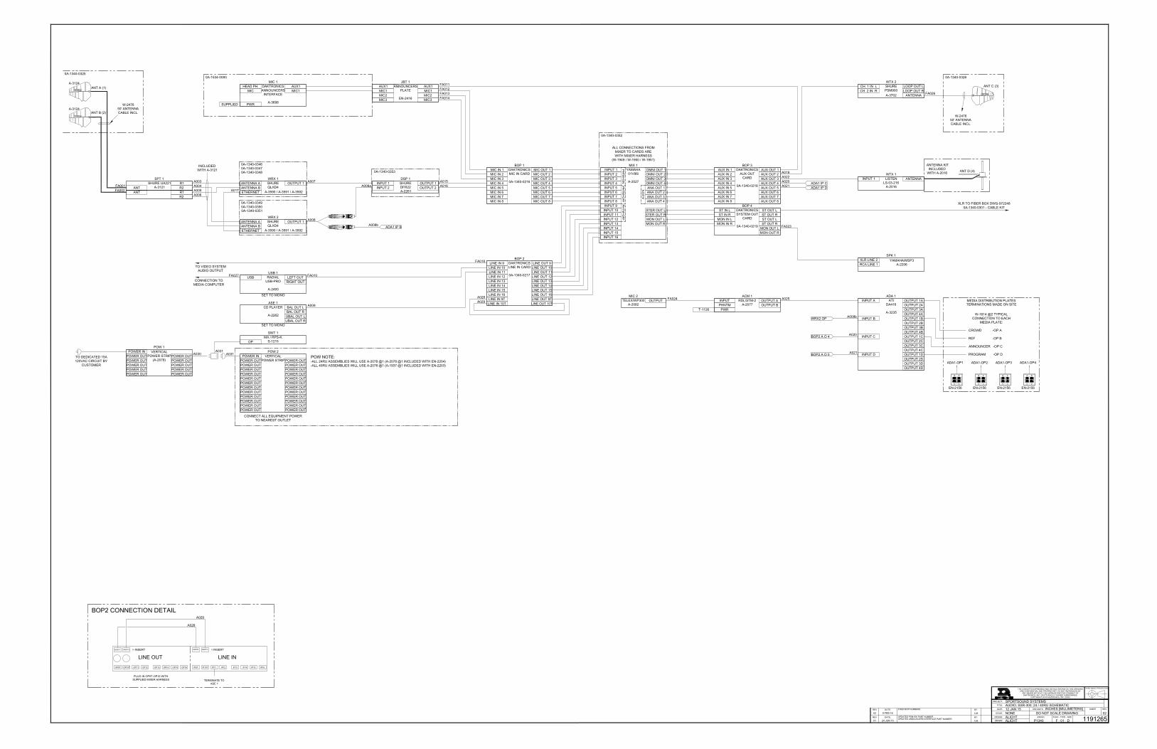
2.1 OverviewReference Drawing:
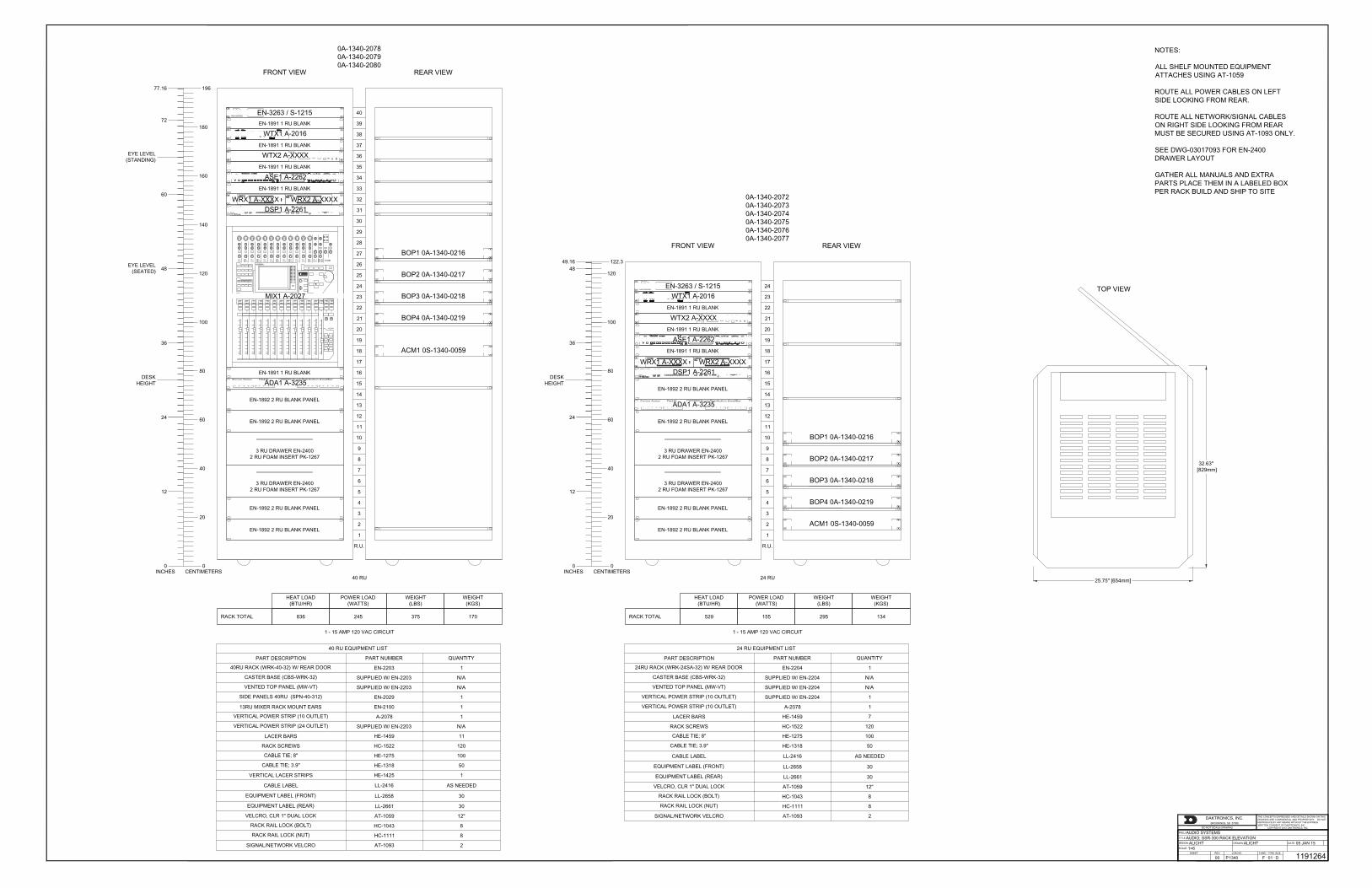
Audio; SSR-300 Rack Elevation ...................................................................................Drawing D-1191264Audio; SSR-300; 24 / 40RU Schematic ........................................................................Drawing D-1191265
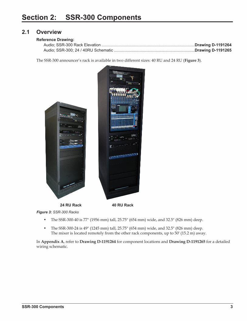
The SSR-300 announcer’s rack is available in two different sizes: 40 RU and 24 RU (Figure 3).
• The SSR-300-40 is 77" (1956 mm) tall, 25.75" (654 mm) wide, and 32.5" (826 mm) deep.
• The SSR-300-24 is 49" (1245 mm) tall, 25.75" (654 mm) wide, and 32.5" (826 mm) deep. The mixer is located remotely from the other rack components, up to 50' (15.2 m) away.
In Appendix A, refer to Drawing D-1191264 for component locations and Drawing D-1191265 for a detailed wiring schematic.
2 1
5
3
6
4
8
9
7
40 RU Rack24 RU Rack
Figure 3: SSR-300 Racks
4 SSR-300 Components
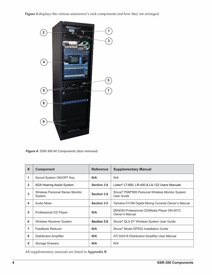
Figure 4 displays the various announcer’s rack components and how they are arranged.
# Component Reference Supplementary Manual
1 Sound System ON/OFF Key N/A N/A
2 ADA Hearing Assist System Section 3.9 Listen® LT-800, LR-400 & LA-122 Users Manuals
3 Wireless Personal Stereo Monitor System Section 3.8 Shure® PSM®900 Personal Wireless Monitor System
User Guide
4 Audio Mixer Section 3.5 Yamaha 01V96 Digital Mixing Console Owner’s Manual
5 Professional CD Player N/A DENON Professional CD/Media Player DN-501C Owner’s Manual
6 Wireless Receiver System Section 3.6 Shure® QLX-D® Wireless System User Guide
7 Feedback Reducer N/A Shure® Model DFR22 Installation Guide
8 Distribution Amplifier N/A ATI DA416 Distribution Amplifier User Manual
9 Storage Drawers N/A N/A
All supplementary manuals are listed in Appendix B.
2 1
5
3
6
4
8
9
7
40 RU Rack24 RU RackFigure 4: SSR-300-40 Components (door removed)

SSR-300 Components 5
2.2 Standard EquipmentAudio MixerThe Yamaha 01V96 Digital Mixer (Figure 5) provides the performance and reliability of digital live sound in a compact design. Small but powerful, this mixer handles up to 40 inputs and offers 24 bit/96 kHz operation for optimum resolution and quality of sound. Other features include:
• Precise 24-bit/96-kHz audio and high-performance head amps
• Up to 40 simultaneous inputs and 20 mix buses in a compact rack-size mixer
• Flexible, independent compression and gating/ducking processors
• Top-performance 24-bit/96kHz effect processors built-in
• Powerful channel functions with flexible control and digital patching capability
• Comprehensive interface with large LCD, 100 mm motor faders, and dedicated scene memory keys (up to 99 scenes)
Professional CD/Media Player
The DN-501C (Figure 6) is a professional, rack-mount CD/Media Player with a combination of flexible file formats and comprehensive inputs and outputs. Other features include:
• Supports CD-DA/WAV/MP3/AAC/AIFF audio file formats
• USB mass storage device playback, including direct digital playback from iPod/iPhone
• Balanced analog and digital AES/EBU outputs (XLR)
• Unbalanced analog and digital coaxial outputs (RCA)
• ±16% Pitch Control
• IR, RS-232c (9-pin D-sub), and GPIO (25-pin D-sub) controllable
Announcer’s InterfaceThe Daktronics Announcer’s Interface (Figure 7) includes one (1) balanced MIC output, one (1) balanced AUX input, and headphone jacks; headphone volume control knob; and momentary or continuous microphone activation buttons. Microphone and headphones are provided.
Figure 5: Audio Mixer
Figure 6: Professional CD Player
Figure 7: Announcer’s Interface Kit
6 SSR-300 Components
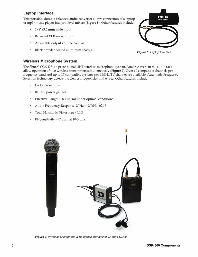
Laptop InterfaceThis portable, durable balanced audio converter allows connection of a laptop or mp3/music player into pro-level mixers (Figure 8). Other features include:
• 1/8" (3.5 mm) male input
• Balanced XLR male output
• Adjustable output volume control
• Black powder-coated aluminum chassis
Wireless Microphone SystemThe Shure® QLX-D® is a professional UHF wireless microphone system. Dual receivers in the audio rack allow operation of two wireless transmitters simultaneously (Figure 9). Over 60 compatible channels per frequency band and up to 17 compatible systems per 6 MHz TV channel are available. Automatic Frequency Selection technology detects the clearest frequencies in the area. Other features include:
• Lockable settings
• Battery power gauges
• Effective Range: 328' (100 m) under optimal conditions
• Audio Frequency Response: 20Hz to 20kHz, ±2dB
• Total Harmonic Distortion: <0.1%
• RF Sensitivity: -97 dBm at 10-5 BER
Figure 8: Laptop Interface
Figure 9: Wireless Microphone & Bodypack Transmitter w/ Mute Switch
SSR-300 Components 7
Distribution AmplifierThe ATI DA416S Quad Distribution Amplifier is a four-input, sixteen-output distribution amplifier that accepts four input signals and distributes each input to four individually adjustable, active balanced outputs. Other features include:
• Separate LEDs for each 1x4 channel indicate input signal presence
• Phoenix connectors for easy pre-wiring and flexible output channel assignment
• Individual wide range audio taper output level controls
Feedback ReducerThe Shure® DFR22 is a two-input, two-output digital audio processor with feedback reduction. The 2 x 2 matrix mixer allows either or both inputs to be routed to either or both outputs, with additional controls for levels and polarity. The unit stores sixteen presets and provides 24-bit conversion, 48kHz sampling and a minimum dynamic range of 100 dB. Other features include:
• Digital feedback reducer, in both mono and stereo processors
• Automatic gain control
• Parametric and graphic equalizers
• Mono & stereo compressor/limiter
• Ducker
• Two-way crossover & splitter
• Subwoofer control
• Peak stop limiter
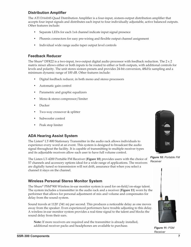
ADA Hearing Assist SystemThe Listen® LT-800 Stationary Transmitter in the audio rack allows individuals to experience every word at an event. This system is designed to broadcast the audio signal throughout the facility. It is capable of transmitting to multiple receiver types and its adjustable receivers allow each user to have full volume control.
The Listen LT-4200 Portable FM Receiver (Figure 10) provides users with the choice of 57 channels and accessory options ideal for a wide range of applications. The receivers are digitally tuned so transmission will not drift, assurance that when you select a channel it stays on the channel.
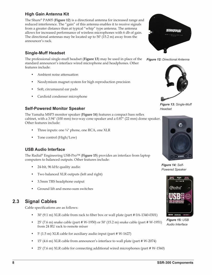
Wireless Personal Stereo Monitor SystemThe Shure® PSM®900 Wireless in-ear monitor system is used for on-field/on-stage talent. The system includes a transmitter in the audio rack and a receiver (Figure 11) worn by the performer that allows for personal adjustment of mix and volume and compensates for delay from the sound system.
Sound travels at 1120' (341 m) per second. This produces a noticeable delay as one moves away from the speaker. Even experienced performers have trouble adjusting to this delay. A wireless in-ear monitor system provides a real-time signal to the talent and blocks the sound delay from their ears.
Note: If more receivers are required and the transmitter is already installed, additional receiver packs and headphones are available to purchase.
Figure 10: Portable FM Receiver
Figure 11: PSM Receiver
8 SSR-300 Components
High Gain Antenna KitThe Shure® PA805 (Figure 12) is a directional antenna for increased range and reduced interference. The “gain” of this antenna enables it to receive signals from a greater distance than at typical “whip” type antenna. The antenna allows for increased performance of wireless microphones with 6 db of gain. The directional antennas may be located up to 50' (15.2 m) away from the announcer’s rack.
Single-Muff HeadsetThe professional single-muff headset (Figure 13) may be used in place of the standard announcer’s interface wired microphone and headphones. Other features include:
• Ambient noise attenuation
• Neodymium magnet system for high reproduction precision
• Soft, circumaural ear pads
• Cardioid condenser microphone
Self-Powered Monitor SpeakerThe Yamaha MSP3 monitor speaker (Figure 14) features a compact bass reflex cabinet, with a 3.94" (100 mm) two-way cone speaker and a 0.87" (22 mm) dome speaker. Other features include:
• Three inputs: one ¼" phone, one RCA, one XLR
• Tone control (High/Low)
USB Audio InterfaceThe Radial® Engineering USB-Pro™ (Figure 15) provides an interface from laptop computers to balanced outputs. Other features include:
• 24-bit, 96 kHz quality audio
• Two balanced XLR outputs (left and right)
• 3.5mm TRS headphone output
• Ground lift and mono-sum switches
2.3 Signal CablesCable specifications are as follows:
• 30' (9.1 m) XLR cable from rack to fiber box or wall plate (part # 0A-1340-0301)
• 25' (7.6 m) snake cable (part # W-1950) or 50' (15.2 m) snake cable (part # W-1951) from 24 RU rack to remote mixer
• 5' (1.5 m) XLR cable for auxiliary audio input (part # W-1627)
• 15' (4.6 m) XLR cable from announcer’s interface to wall plate (part # W-2074)
• 25' (7.6 m) XLR cable for connecting additional wired microphones (part # W-1560)
Figure 12: Directional Antenna
Figure 13: Single-Muff Headset
Figure 14: Self-Powered Speaker
Figure 15: USB Audio Interface
SSR-300 Components 9
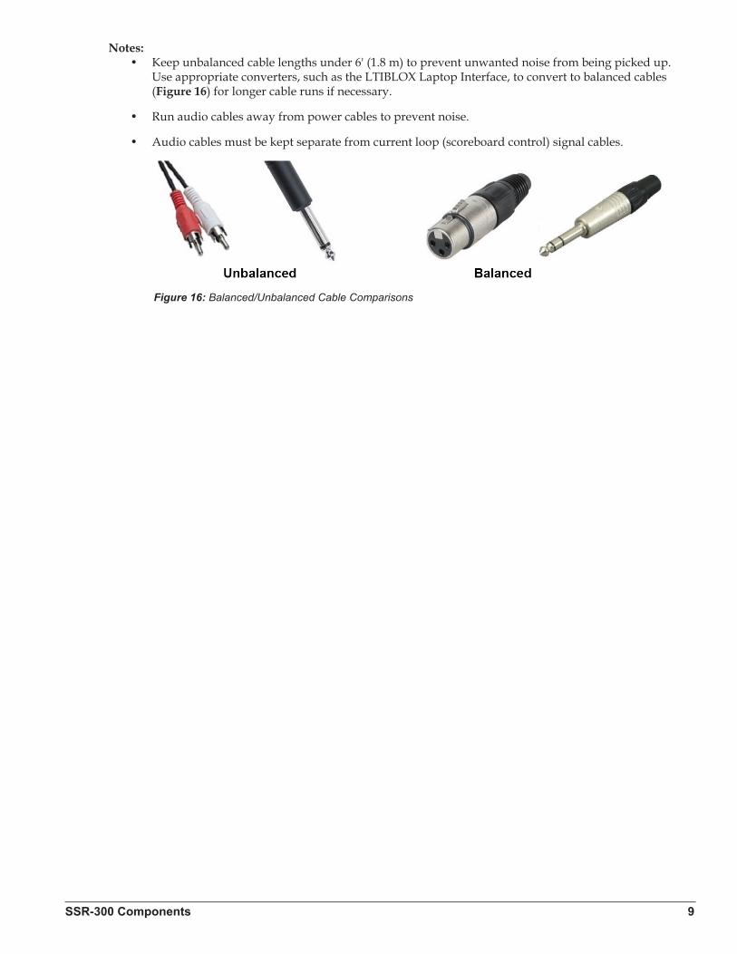
Notes:• Keep unbalanced cable lengths under 6' (1.8 m) to prevent unwanted noise from being picked up.
Use appropriate converters, such as the LTIBLOX Laptop Interface, to convert to balanced cables (Figure 16) for longer cable runs if necessary.
• Run audio cables away from power cables to prevent noise.
• Audio cables must be kept separate from current loop (scoreboard control) signal cables.
Figure 16: Balanced/Unbalanced Cable Comparisons

Setup & Operation 11
Section 3: Setup & Operation
3.1 Power & Signal ConnectionsReference Drawing:
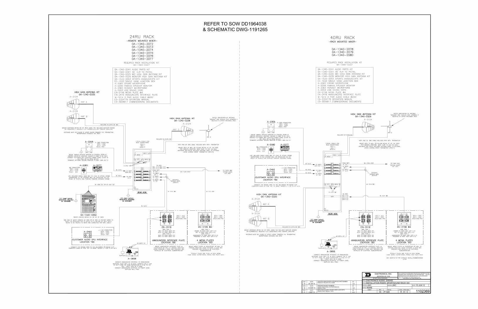
Installation Riser; Sportsound Rack 300 .......................................................................Drawing C-1102369
All connections are made upon installation. Some equipment may be connected and disconnected each time it is used. Drawing C-1102369 in Appendix A shows a general overview of how standard and optional equipment connects to the rack. Note that every project is unique, so be sure to follow any site-specific riser drawings and documentation for the facility to determine the exact layout of system components.
3.2 SetupThe Announcer’s Interface equipment is typically kept in the bottom storage drawers along with other accessories. Follow the steps below to properly reconnect it to the rack. For more information, refer also to the quick guide (DD3083838) shipped with the device.
1. Connect the 2' (610 mm) XLR cable between the microphone and the MIC 1 INPUT jack.
2. Connect headphones to the 1/4" or 1/8" jack.
3. Connect the provided 12 VAC wallpack transformer to the power input jack, and then plug the other end into a standard 120 VAC outlet. Use the tab above the power jack as a strain relief for the power cord.
4. Connect the 15' (4.6 m) XLR cable from MIC 1 & AUX 1 on the announcer’s interface to Mic 1 & Aux 1 on the announcer's plate.
For the 24 RU rack only, there will be a 25' (7.6 m) or 50' (15.2 m) cable harness factory wired to the rack. Route this cable to the desired mixer location and connect each plug to the appropriate jack on the mixer according to the wire labels. Plug the mixer into a standard power outlet.
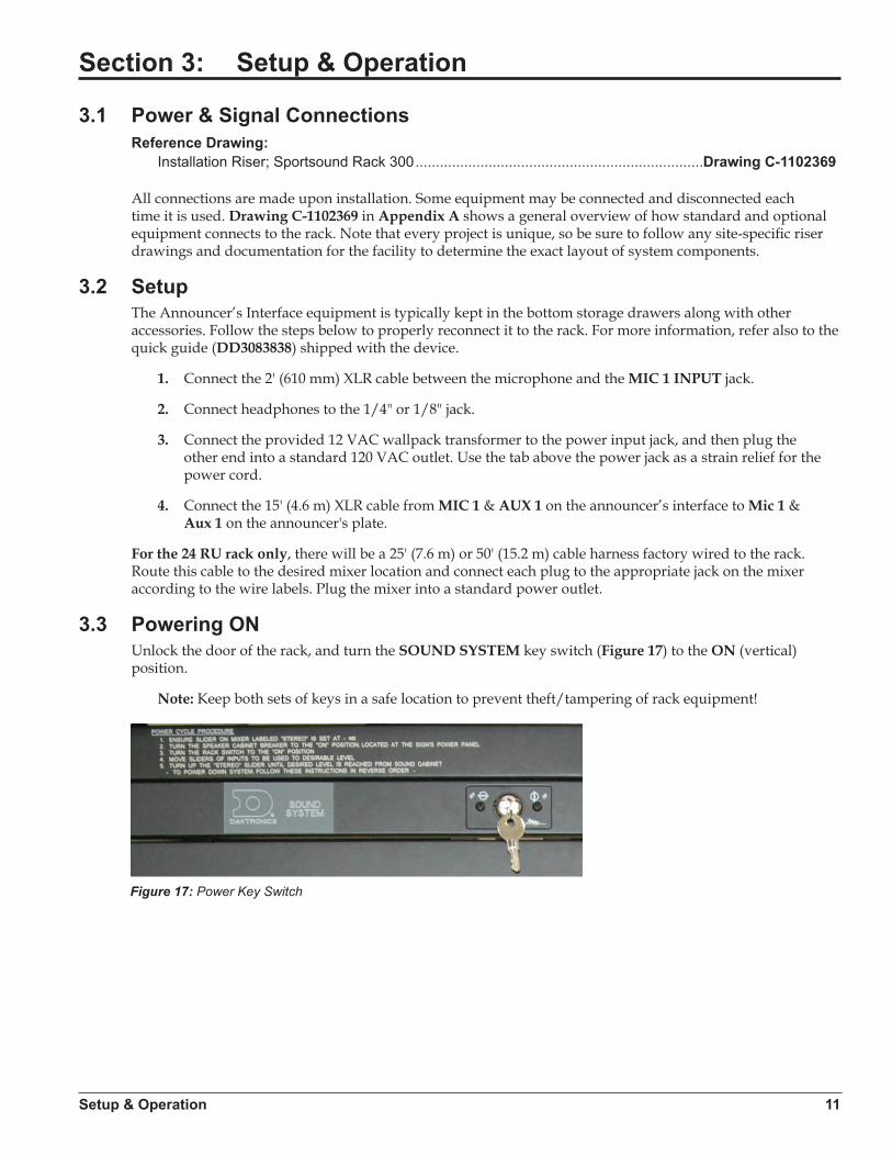
3.3 Powering ONUnlock the door of the rack, and turn the SOUND SYSTEM key switch (Figure 17) to the ON (vertical) position.
Note: Keep both sets of keys in a safe location to prevent theft/tampering of rack equipment!
Figure 17: Power Key Switch

12 Setup & Operation
3.4 Powering Down1. Press the USER DEFINED KEY on mixer labeled OFF (Figure 18).
2. Turn the SOUND SYSTEM key switch to the OFF (horizontal) position.
3. If the system will not be used for some time, unplug the power cord.
4. Place all accessories back in the appropriate slots of the storage drawers to keep them safe and organized.
5. Close and lock the rack door.
3.5 Mixer OperationBasic instructions are described below. For more information about audio mixer operation, refer to the Yamaha 01V96 Digital Mixing Console Owner’s Manual.
1. Press the USER DEFINED KEY labeled GAME (Figure 19).
Note: Custom keys (presets) may have been set up during training. Press the desired key as needed for a specific application. The creation of additional presets is recommended for advanced users only.
2. Ensure all source equipment is turned on and operational (refer to the appropriate sections of this manual and/or manufacturers’ manuals).
3. Verify gain knobs for the channels in use are adjusted so the SIGNAL light is green and the PEAK light is not lit (Figure 20).
4. Ensure the ON buttons for the channels in use and for the STEREO slider are illuminated; also verify no SOLO buttons are illuminated (Figure 21).
Figure 18: OFF Key
Figure 19: GAME Key
Figure 20: Gain Knobs & PEAK/SIGNAL Indicators
Figure 21: Channel & SOLO Buttons
Setup & Operation 13
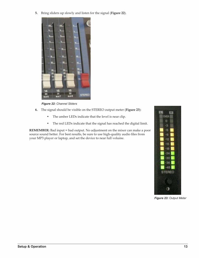
5. Bring sliders up slowly and listen for the signal (Figure 22).
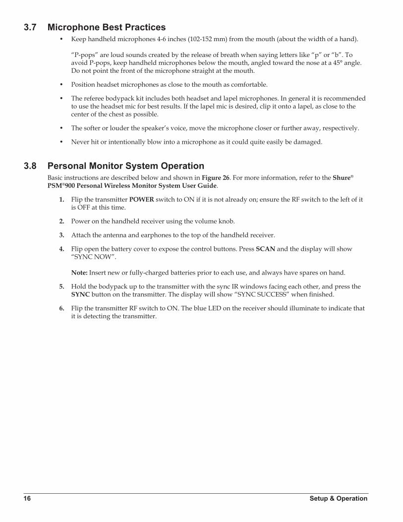
6. The signal should be visible on the STEREO output meter (Figure 23):
• The amber LEDs indicate that the level is near clip.
• The red LEDs indicate that the signal has reached the digital limit.
REMEMBER: Bad input = bad output. No adjustment on the mixer can make a poor source sound better. For best results, be sure to use high-quality audio files from your MP3 player or laptop, and set the device to near full volume.
Figure 22: Channel Sliders
Figure 23: Output Meter

14 Setup & Operation
3.6 Wireless Mic System OperationBasic instructions are described below. For more information about wireless mic system operation, refer to the Shure® QLX-D® Wireless System User Guide.
Note: For systems built prior to January 2015, refer to the Shure® ULX® Wireless System User Guide for setup and operation instructions.
Wireless Receiver
The unit displays the following information (Figure 24):
a. Transmitter Battery Lifeb. TV Channelc. Frequencyd. Group Numbere. Channel Numberf. RF Signal Strengthg. Transmitted Audio Levelh. Gain Level
Single Receiver1. Ensure all transmitters are powered off. Press the power button to turn on the receiver if it is not
already on. 2. Press menu until “scan” displays on the LCD.3. Press enter to start frequency scan. When scan is complete, Group and Channel will display on
the LCD.
Network Receivers1. Ensure all transmitters are powered off. Turn on all receivers and wait one minute to allow time to
connect to the network. 2. Press menu on one receiver until group number flashes.3. Use the arrow buttons to select a group to scan.4. Press enter, wait for channel, and then press enter again5. Press menu until “network scan” displays on the LCD.6. Press enter twice to deploy channels to other receivers.
Note: Perform a scan on all of the wireless units just minutes before the game! If a scan is performed too far ahead of time, frequencies set up by the media later on may interfere with previously configured wireless microphone settings.
PowerIR Window
a
e
b c
d gf h
Power ON/OFF
Power ON/OFF
IR Window
Figure 24: Wireless Receiver LCD & Controls

Setup & Operation 15
Wireless Mic & Bodypack Operation
1. Open the battery cover. Insert new or fully-charged AA batteries prior to each use, and always have spares on hand.
2. Power on the transmitter device (Figure 25).
3. Hold the transmitter device up close to one receiver in the rack, ensuring the infrared (IR) windows are aligned.
4. Press sync on the receiver; “good” will display if sync was successful.
5. Repeat steps 1-4 to pair another transmitter device with an additional receiver (if present).
Note: Plug the referee mute switch into the jack on top of the bodypack unit and plug headphones/lapel mic into the referee mute switch.
Verify Reception: With a transmitter and the receiver both turned on and having matching GROUP and Channel numbers, the RF meter on the receiver should be indicating signal. Speak into the microphone and the TX AUDIO meter should indicate signal presence.
Additional Tips:
• Perform a group and channel scan to obtain the best available channel for microphones.
• Check that battery levels are adequate to prevent wireless equipment from powering off during use.
• Program one microphone per receiver; multiple microphones on the same channel will cause interference and microphones will drop out.
• Always use quality batteries to prevent battery leaks that can corrode and shorten the life of the equipment.
PowerIR Window
a
e
b c
d gf h
Power ON/OFF
Power ON/OFF
IR Window
Figure 25: Wireless Mic & Bodypack Controls
16 Setup & Operation
3.7 Microphone Best Practices• Keep handheld microphones 4-6 inches (102-152 mm) from the mouth (about the width of a hand).
“P-pops” are loud sounds created by the release of breath when saying letters like “p” or “b”. To avoid P-pops, keep handheld microphones below the mouth, angled toward the nose at a 45° angle. Do not point the front of the microphone straight at the mouth.
• Position headset microphones as close to the mouth as comfortable.
• The referee bodypack kit includes both headset and lapel microphones. In general it is recommended to use the headset mic for best results. If the lapel mic is desired, clip it onto a lapel, as close to the center of the chest as possible.
• The softer or louder the speaker’s voice, move the microphone closer or further away, respectively.
• Never hit or intentionally blow into a microphone as it could quite easily be damaged.
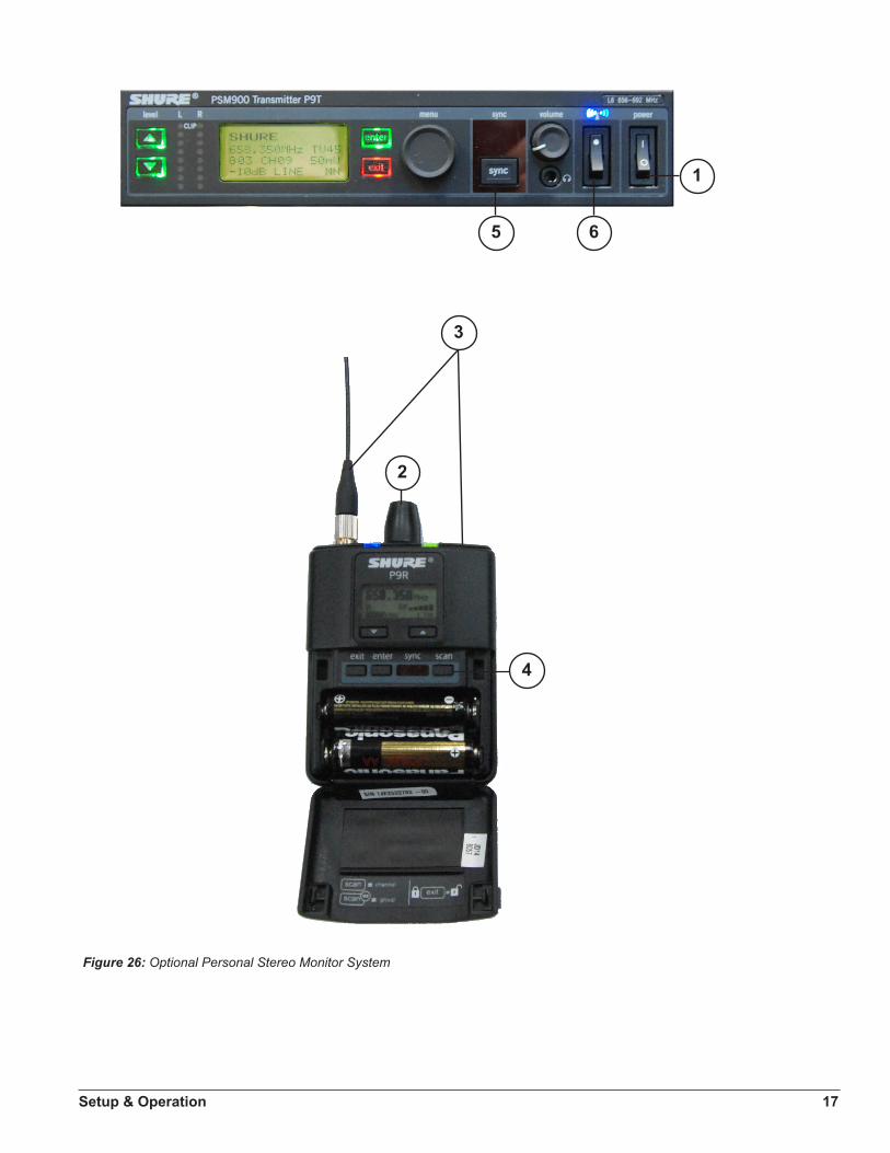
3.8 Personal Monitor System OperationBasic instructions are described below and shown in Figure 26. For more information, refer to the Shure® PSM®900 Personal Wireless Monitor System User Guide.
1. Flip the transmitter POWER switch to ON if it is not already on; ensure the RF switch to the left of it is OFF at this time.
2. Power on the handheld receiver using the volume knob.
3. Attach the antenna and earphones to the top of the handheld receiver.
4. Flip open the battery cover to expose the control buttons. Press SCAN and the display will show “SYNC NOW”. Note: Insert new or fully-charged batteries prior to each use, and always have spares on hand.
5. Hold the bodypack up to the transmitter with the sync IR windows facing each other, and press the SYNC button on the transmitter. The display will show “SYNC SUCCESS” when finished.
6. Flip the transmitter RF switch to ON. The blue LED on the receiver should illuminate to indicate that it is detecting the transmitter.
Setup & Operation 17
1
5 6
3
2
4
Figure 26: Optional Personal Stereo Monitor System
18 Setup & Operation
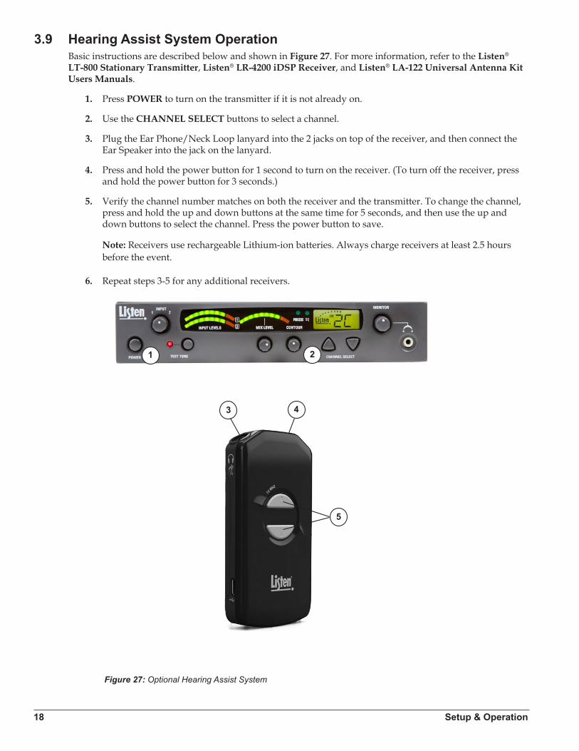
3.9 Hearing Assist System OperationBasic instructions are described below and shown in Figure 27. For more information, refer to the Listen® LT-800 Stationary Transmitter, Listen® LR-4200 iDSP Receiver, and Listen® LA-122 Universal Antenna Kit Users Manuals.
1. Press POWER to turn on the transmitter if it is not already on.
2. Use the CHANNEL SELECT buttons to select a channel.
3. Plug the Ear Phone/Neck Loop lanyard into the 2 jacks on top of the receiver, and then connect the Ear Speaker into the jack on the lanyard.
4. Press and hold the power button for 1 second to turn on the receiver. (To turn off the receiver, press and hold the power button for 3 seconds.)
5. Verify the channel number matches on both the receiver and the transmitter. To change the channel, press and hold the up and down buttons at the same time for 5 seconds, and then use the up and down buttons to select the channel. Press the power button to save.
Note: Receivers use rechargeable Lithium-ion batteries. Always charge receivers at least 2.5 hours before the event.
6. Repeat steps 3-5 for any additional receivers.
1 2
3 4
5
Figure 27: Optional Hearing Assist System
Maintenance & Troubleshooting 19
Section 4: Maintenance & Troubleshooting
4.1 Maintenance• Unplug rack (and fiber box, if included) from power during periods of non-use.
• Store equipment in a clean dry place free from moisture, debris, and extreme temperatures.
• Keep announcers rack and equipment covered from dust and debris when not in use.
• Clean equipment annually or as needed using electronic equipment duster and a dry cloth.
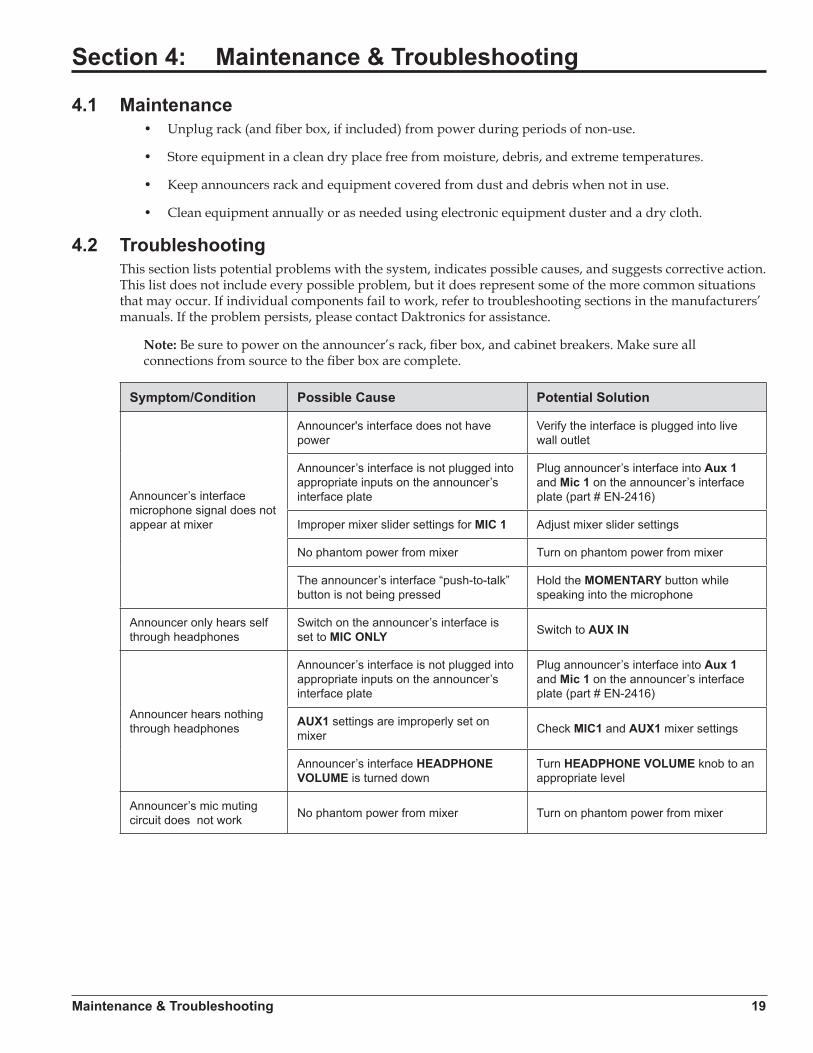
4.2 TroubleshootingThis section lists potential problems with the system, indicates possible causes, and suggests corrective action. This list does not include every possible problem, but it does represent some of the more common situations that may occur. If individual components fail to work, refer to troubleshooting sections in the manufacturers’ manuals. If the problem persists, please contact Daktronics for assistance.
Note: Be sure to power on the announcer’s rack, fiber box, and cabinet breakers. Make sure all connections from source to the fiber box are complete.
Symptom/Condition Possible Cause Potential Solution
Announcer’s interface microphone signal does not appear at mixer
Announcer's interface does not have power
Verify the interface is plugged into live wall outlet
Announcer’s interface is not plugged into appropriate inputs on the announcer’s interface plate
Plug announcer’s interface into Aux 1 and Mic 1 on the announcer’s interface plate (part # EN-2416)
Improper mixer slider settings for MIC 1 Adjust mixer slider settings
No phantom power from mixer Turn on phantom power from mixer
The announcer’s interface “push-to-talk” button is not being pressed
Hold the MOMENTARY button while speaking into the microphone
Announcer only hears self through headphones
Switch on the announcer’s interface is set to MIC ONLY Switch to AUX IN
Announcer hears nothing through headphones
Announcer’s interface is not plugged into appropriate inputs on the announcer’s interface plate
Plug announcer’s interface into Aux 1 and Mic 1 on the announcer’s interface plate (part # EN-2416)
AUX1 settings are improperly set on mixer Check MIC1 and AUX1 mixer settings
Announcer’s interface HEADPHONE VOLUME is turned down
Turn HEADPHONE VOLUME knob to an appropriate level
Announcer’s mic muting circuit does not work No phantom power from mixer Turn on phantom power from mixer

20 Maintenance & Troubleshooting
Symptom/Condition Possible Cause Potential Solution
For Wireless
No signal present at mixer from wireless microphones
The battery is not installed properly in the transmitter Reinstall the battery properly
The battery is not providing full power Charge or replace battery
The transmitter is not switched to the ON position Switch the transmitter to the ON position
The transmitter and receiver are set to different channels Set to same channel
Interference on wireless equipment
Competing RF equipment within frequency band
1. Scan for clearest group/channel on microphone receiver.
2. Switch wireless receiver and transmitter to an available clear channel (Section 3.6).
Low audio signal from wireless device
Improper gain adjustment on mixer input Set proper mixer input gain levels
Improper gain adjustment on transmitter output
Set proper transmitter output gain levels (refer to Shure® Wireless System User Guide)
Wireless microphone is cutting out
The battery is not providing full power. Charge or replace battery.
Transmitter and Receiver Antenna are not in line of sight.
Relocate receiver antenna to be in clear line of sight to field.
Note: If signal goes through tinted glass, antennas may need to be relocated outside (High Gain Antenna Kit required).
Ensure referee is placing transmitter on belt properly. Refer to Referee Mic Best Practice (DD2945 863).
Proper wireless frequency is not selected for the area.
1. Go to http://www.shure.com/americas/support/tools/wireless-frequency-finder
2. Enter the ZIP Code of the facility, select QLX-D as the Wireless Series, and then click Search.
3. Ensure the wireless receiver is set to the proper Group & (Reserved) Channel for the Band in use, and then sync the transmitter(s) to the receiver.
Low wireless signal strengthIf all of the above solutions have been performed, order a High Gain Antenna kit to increase signal strength.
Replacement Parts 21
Section 5: Replacement Parts
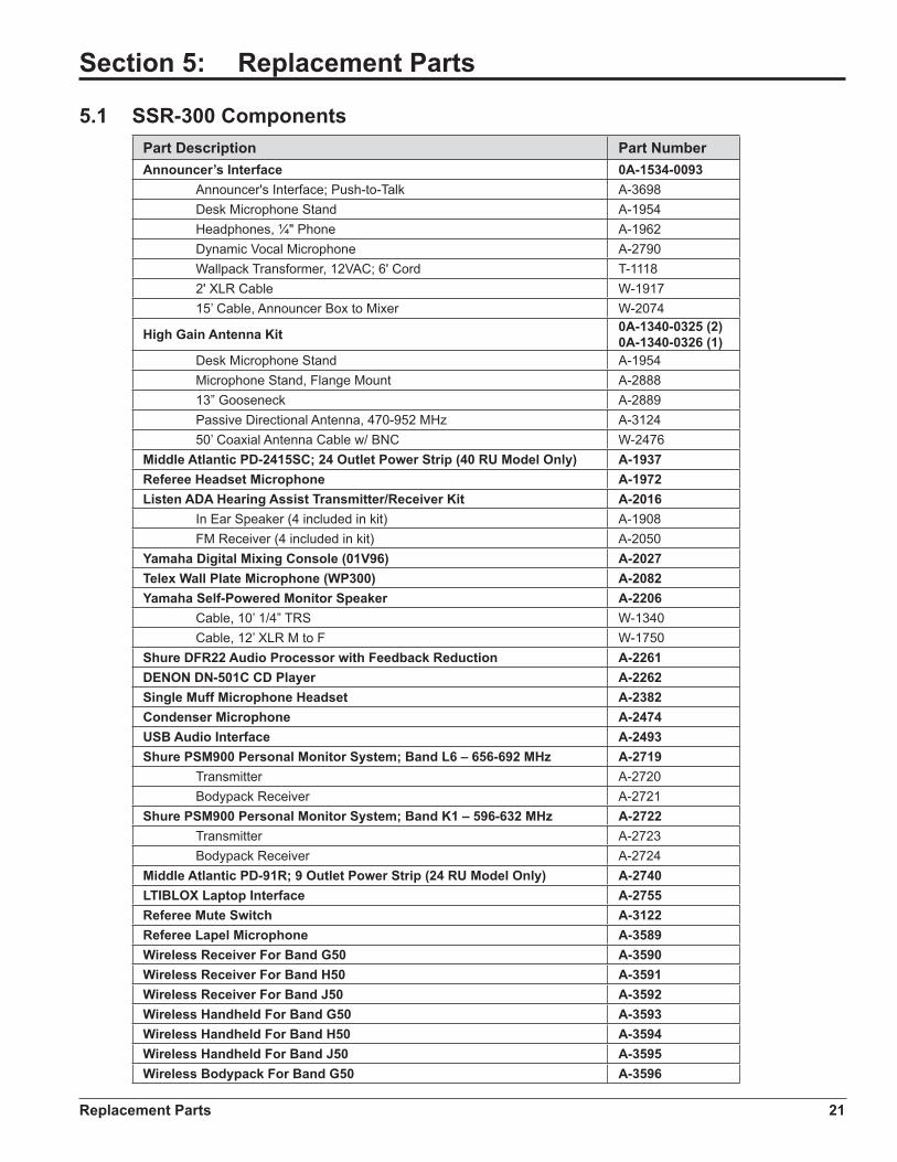
5.1 SSR-300 ComponentsPart Description Part NumberAnnouncer’s Interface 0A-1534-0093 Announcer's Interface; Push-to-Talk A-3698 Desk Microphone Stand A-1954 Headphones, ¼" Phone A-1962 Dynamic Vocal Microphone A-2790 Wallpack Transformer, 12VAC; 6' Cord T-1118 2' XLR Cable W-1917 15’ Cable, Announcer Box to Mixer W-2074
High Gain Antenna Kit 0A-1340-0325 (2)0A-1340-0326 (1)
Desk Microphone Stand A-1954 Microphone Stand, Flange Mount A-2888 13” Gooseneck A-2889 Passive Directional Antenna, 470-952 MHz A-3124 50’ Coaxial Antenna Cable w/ BNC W-2476Middle Atlantic PD-2415SC; 24 Outlet Power Strip (40 RU Model Only) A-1937Referee Headset Microphone A-1972Listen ADA Hearing Assist Transmitter/Receiver Kit A-2016 In Ear Speaker (4 included in kit) A-1908 FM Receiver (4 included in kit) A-2050Yamaha Digital Mixing Console (01V96) A-2027Telex Wall Plate Microphone (WP300) A-2082Yamaha Self-Powered Monitor Speaker A-2206 Cable, 10’ 1/4” TRS W-1340 Cable, 12’ XLR M to F W-1750Shure DFR22 Audio Processor with Feedback Reduction A-2261DENON DN-501C CD Player A-2262Single Muff Microphone Headset A-2382Condenser Microphone A-2474USB Audio Interface A-2493Shure PSM900 Personal Monitor System; Band L6 – 656-692 MHz A-2719 Transmitter A-2720 Bodypack Receiver A-2721Shure PSM900 Personal Monitor System; Band K1 – 596-632 MHz A-2722 Transmitter A-2723 Bodypack Receiver A-2724Middle Atlantic PD-91R; 9 Outlet Power Strip (24 RU Model Only) A-2740LTIBLOX Laptop Interface A-2755Referee Mute Switch A-3122Referee Lapel Microphone A-3589Wireless Receiver For Band G50 A-3590Wireless Receiver For Band H50 A-3591Wireless Receiver For Band J50 A-3592Wireless Handheld For Band G50 A-3593Wireless Handheld For Band H50 A-3594Wireless Handheld For Band J50 A-3595Wireless Bodypack For Band G50 A-3596

22 Replacement Parts
Part Description Part NumberWireless Bodypack For Band H50 A-3597Wireless Bodypack For Band J50 A-3598Wireless Accessories Passive Antenna Combiner A-3121 Black Cloth Pouch for Bodypack A-3123ATI Quad Distribution Amplifier (DA416S) A-3235Media Panel Jack Plate EN-2156Announcer’s Interface Plate EN-2416Cable, 25’ XLR M to F W-1560Cable, 5’ XLR M to F W-1627
Daktronics Exchange and Repair & Return Programs 23
Section 6: Daktronics Exchange and Repair & Return Programs
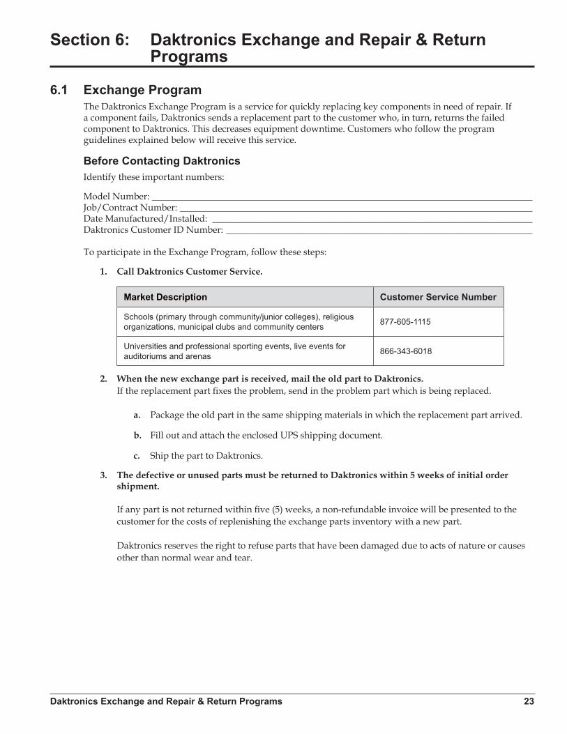
6.1 Exchange ProgramThe Daktronics Exchange Program is a service for quickly replacing key components in need of repair. If a component fails, Daktronics sends a replacement part to the customer who, in turn, returns the failed component to Daktronics. This decreases equipment downtime. Customers who follow the program guidelines explained below will receive this service.
Before Contacting DaktronicsIdentify these important numbers:
Model Number: __________________________________________________________________________________Job/Contract Number: ____________________________________________________________________________Date Manufactured/Installed: _____________________________________________________________________Daktronics Customer ID Number: __________________________________________________________________
To participate in the Exchange Program, follow these steps:
1. Call Daktronics Customer Service.
Market Description Customer Service Number
Schools (primary through community/junior colleges), religious organizations, municipal clubs and community centers 877-605-1115
Universities and professional sporting events, live events for auditoriums and arenas 866-343-6018
2. When the new exchange part is received, mail the old part to Daktronics. If the replacement part fixes the problem, send in the problem part which is being replaced.
a. Package the old part in the same shipping materials in which the replacement part arrived.
b. Fill out and attach the enclosed UPS shipping document.
c. Ship the part to Daktronics.
3. The defective or unused parts must be returned to Daktronics within 5 weeks of initial order shipment. If any part is not returned within five (5) weeks, a non-refundable invoice will be presented to the customer for the costs of replenishing the exchange parts inventory with a new part. Daktronics reserves the right to refuse parts that have been damaged due to acts of nature or causes other than normal wear and tear.

24 Daktronics Exchange and Repair & Return Programs
6.2 Repair & Return ProgramFor items not subject to exchange, Daktronics offers a Repair & Return Program. To send a part for repair, follow these steps:
1. Call or fax Daktronics Customer Service. Refer to the appropriate market phone number in the chart on the previous page. Fax: 605-697-4444
2. Receive a case number before shipping. This expedites repair of the part.
3. Package and pad the item carefully to prevent damage during shipment. Electronic components, such as as printed circuit boards, should be placed in an antistatic bag before boxing. Daktronics does not recommend using packing peanuts when shipping.
4. Enclose:• name• address• phone number• the case number• a clear description of symptoms
Shipping AddressDaktronics Customer Service[Case #]201 Daktronics Drive, Dock EBrookings, SD 57006
6.3 Daktronics Warranty & Limitation of LiabilityThe Daktronics Warranty & Limitation of Liability is located in Appendix C. The Warranty is independent of Extended Service agreements and is the authority in matters of service, repair, and display operation.
Reference Drawings 25
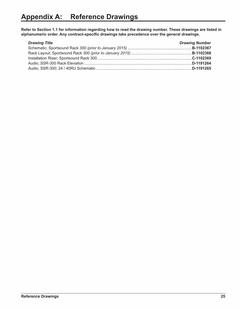
Appendix A: Reference DrawingsRefer to Section 1.1 for information regarding how to read the drawing number. These drawings are listed in alphanumeric order. Any contract-specific drawings take precedence over the general drawings.
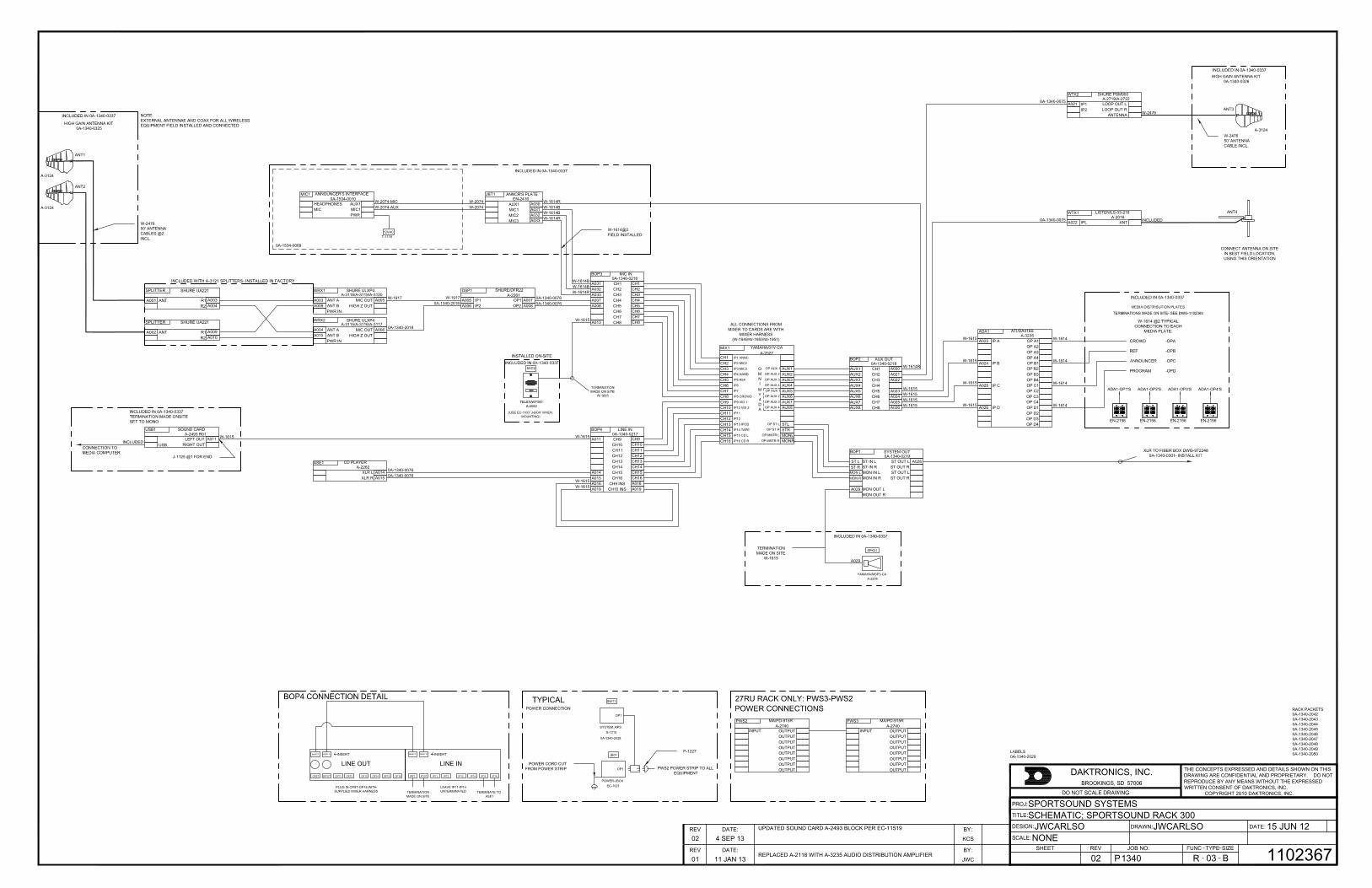
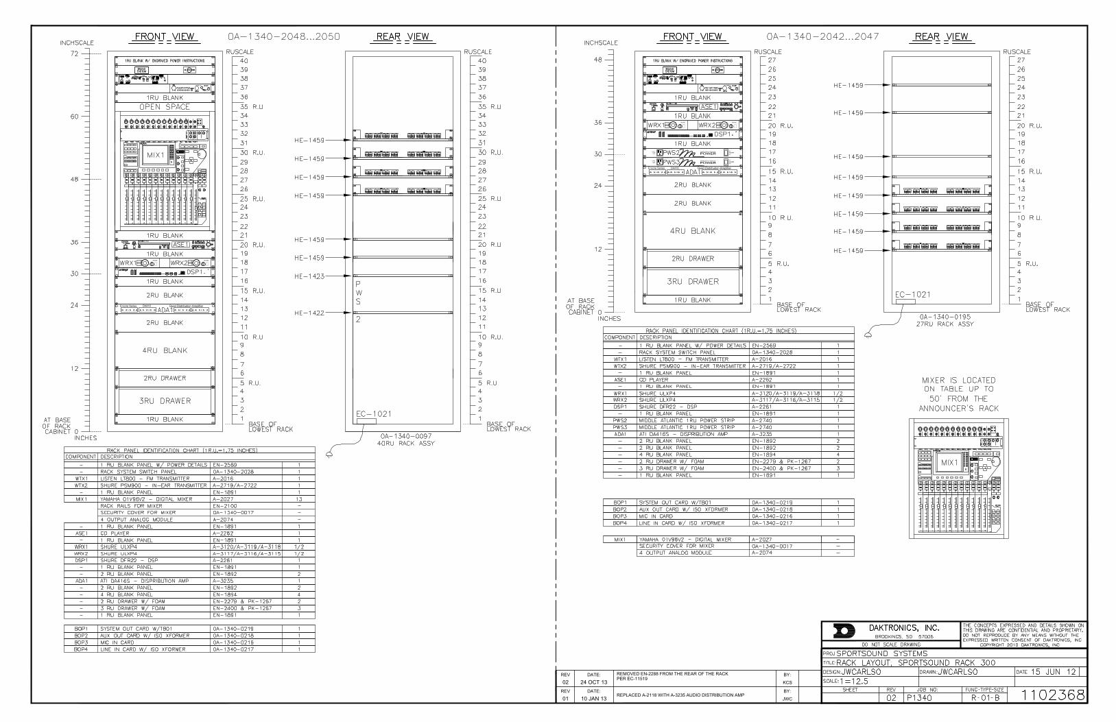
Drawing Title Drawing NumberSchematic; Sportsound Rack 300 (prior to January 2015) ...........................................................B-1102367Rack Layout; Sportsound Rack 300 (prior to January 2015) ........................................................B-1102368Installation Riser; Sportsound Rack 300 .......................................................................................C-1102369Audio; SSR-300 Rack Elevation ...................................................................................................D-1191264Audio; SSR-300; 24 / 40RU Schematic ........................................................................................D-1191265

ALL CONNECTIONS FROMMIXER TO CARDS ARE WITH
MIXER HARNESS(W-1949/W-1950/W-1951)
OP1
OP1 PWS2 POWER STRIP TO ALLEQUIPMENT
LABELS0A-1340-2029
EN-2156
ADA1-OP1'S ADA1-OP2'S ADA1-OP3'S
EN-2156 EN-2156
EC-1021POWER-JBOX
JB01
S-1215SYSTEM_RPS
SWT1
ANT2
0A-1340-2028
(USE EC-1033 'J-BOX' WHENMOUNTING)
RACK PACKETS0A-1340-20420A-1340-20430A-1340-20440A-1340-20450A-1340-20460A-1340-20470A-1340-20480A-1340-20490A-1340-2050
OP9T OP10T OP11 OP13OP12 OP14 OP15 OP16 IP9T IP10T IP11 IP12 IP13 IP14 IP15 IP16
LINE INLINE OUTINSRT9 INSRT10 INSRT9 INSRT10INSERT INSERT
TERMINATIONMADE ON SITE
PLUG IN OP9T-OP16 WITHSUPPLIED MIXER HARNESS TERMINATE TO
ASE1
LEAVE IP11-IP14UNTERMINATED
ADA1-OP4'S
EN-2156
YAMAHA/01V-CA
IP1 ANNC.IP2 MIC2IP3 MIC3IP4 HAND
OP AUX 1OP AUX 2
OP AUX 3OP AUX 4
IP7
IP5 REF
IP6
IP9 VID 1
IP8 CROWD
OP ST LOP ST R
OP MNTR L
OP MNTR R
IP10 VID 2IP11IP12
IP13 IPODIP14 TAPEIP15 CD L
IP16 CD R
A-2027
OMNI
OP AUX 1OP AUX 2
OP AUX 3OP AUX 4
MY4DA
MIX1
CH1CH2CH3CH4CH5CH6CH7CH8CH9CH10CH11CH12CH13CH14CH15CH16
AUX1AUX2AUX3AUX4AUX5AUX6AUX7AUX8
STLSTRMONLMONR
SHURE/DFR22
IP1 OP1OP2
A-2261
IP2
DSP1
A005A006
A007A008
W-19170A-1340-2018
0A-1340-00760A-1340-0076
LISTEN/LS-03-216
IPL ANTA-2016
WTX1
A0220A-1340-0075 INCLUDED
AUX OUT0A-1340-0218
CH3CH4CH5CH6CH7CH8
CH2CH1
BOP2
AUX1AUX2AUX3AUX4AUX5AUX6AUX7AUX8
A030A021A022
A023A024A025A026
W-1614R
W-1615W-1615W-1615W-1615
LINE IN0A-1340-0217
CH11CH12CH13CH14CH15CH16
CH10CH9
CH9 INSCH10 INS
BOP4
A011
A014A015A016A019
CH9CH10CH11CH12CH13CH14CH15CH16A016A019
W-1615
W-1615W-1615
MIC IN0A-1340-0216
CH3CH4CH5CH6CH7CH8
CH2CH1
BOP3
A031A032A033A007A008
A013
CH1CH2CH3CH4CH5CH6CH7CH8
W-1614BW-1614BW-1614R
W-1615
ANT A MIC OUT
SHURE ULXP4
ANT B HIGH Z OUTPWR IN
WRX1A-3118/A-3119/A-3120
A003A009
A005 W-1917
ANT A MIC OUT
SHURE ULXP4
ANT B HIGH Z OUTPWR IN
WRX2A-3115/A-3116/A-3117
A004A010
A006 0A-1340-2018
CD PLAYER
XLR LXLR R
ASE1A-2262
A014A015
0A-1340-00760A-1340-0076
HEADPHONES AUX1
ANNOUNCER'S INTERFACE
MIC MIC1
T-111812VAC
PWR
0A-1534-0069
MIC1
W-2074-MICW-2074-AUX
0A-1534-0010ANNCR'S PLATE
AUX1MIC1MIC2
EN-2416
MIC3
JBT1
A030A031A032A033
W-2074W-2074
W-1614RW-1614BW-1614BW-1614R
SHURE PSM900
IP1IP2
LOOP OUT LLOOP OUT R
ANTENNA
WTX2A-2719/A-2722
A0210A-1340-0075
W-2476
YAMAHA/MSP3-CAA-2206
SPK01
A029
TERMINATIONMADE ON SITE
W-1615
SHURE UA221
ANT R1R2
SPLITTER
A001 A003A004
SHURE UA221
ANT R1R2
SPLITTER
A002 A009A010
INCLUDED WITH A-3121 SPLITTERS- INSTALLED IN FACTORY
CONNECT ANTENNA ON SITEIN BEST FIELD LOCATION,USING THIS ORIENTATION
HIGH GAIN ANTENNA KIT0A-1340-0325
W-247650' ANTENNACABLES @2INCL.
A-3124
ANT1
A-3124
HIGH GAIN ANTENNA KIT0A-1340-0326
A-3124
ANT3
W-247650' ANTENNACABLE INCL.
ANT4
W-1614@2FIELD INSTALLED
P-1227
POWER CORD CUTFROM POWER STRIP
MA/PD-915R
INPUT OUTPUTOUTPUTOUTPUTOUTPUTOUTPUTOUTPUTOUTPUTOUTPUT
PWS2A-2740
MA/PD-915R
INPUT OUTPUTOUTPUTOUTPUTOUTPUTOUTPUTOUTPUTOUTPUTOUTPUT
PWS3A-2740
INCLUDED IN 0A-1340-0337
THE CONCEPTS EXPRESSED AND DETAILS SHOWN ON THISDRAWING ARE CONFIDENTIAL AND PROPRIETARY. DO NOTREPRODUCE BY ANY MEANS WITHOUT THE EXPRESSEDWRITTEN CONSENT OF DAKTRONICS, INC.
COPYRIGHT 2010 DAKTRONICS, INC.
DAKTRONICS, INC.
BH
DRAWN: DATE:
SHEET JOB NO:REV
SPORTSOUND SYSTEMSSCHEMATIC; SPORTSOUND RACK 300
JWCARLSO 15 JUN 12
P1340 R 03 B
NONEJWCARLSO
110236702DATE:REV BY:
01 11 JAN 13 JWCREPLACED A-2118 WITH A-3235 AUDIO DISTRIBUTION AMPLIFIER
SOUND CARD
USBLEFT OUT
RIGHT OUT
A-2493 R01USB1
A011INCLUDED
W-1615
J-1125 @1 FOR END
DATE:REV BY:02 4 SEP 13 KCS
UPDATED SOUND CARD A-2493 BLOCK PER EC-11519
ST LST RMON LMON R
ST IN R ST OUT RST OUT LST OUT R
SYSTEM OUT0A-1340-0219
MON IN LMON IN R
MON OUT LMON OUT R
ST IN L ST OUT L
BOP1
A029
A028
ATI/DA416S
IP A
OP B1OP B2
OP A1OP A2OP A3OP A4
OP B3OP B4
IP B
OP C1OP C2
IP C
OP C3OP C4OP D1OP D2OP D3OP D4
IP D
ADA1
A023
A024
A025
A026
W-1615
W-1615
W-1615
W-1615
W-1614
W-1614
W-1614
W-1614
A-3235
SHURE
SET
POWERSHURE
SET
POWER
SHURE
SET
POWERSHURE
SET
POWER
ON
OFF
115 VOLT15 AMP
60 HZ
POWER CENTER PD-915R
MASTER
ON
OFF
115 VOLT15 AMP
60 HZ
POWER CENTER PD-915R
MASTER
DATE:REV BY:01 10 JAN 13 JWC
REPLACED A-2118 WITH A-3235 AUDIO DISTRIBUTION AMP
A1 2 3 4
B4321
D4321
C1 2 3 4
Quad Distribution AmplifierEncore Series DA416
A1 2 3 4
B4321
D4321
C1 2 3 4
Quad Distribution AmplifierEncore Series DA416
DATE:REV BY:02 24 OCT 13 KCS
REMOVED EN-2288 FROM THE REAR OF THE RACKPER EC-11519
+6 BALANCED
REFCROWD
ANNCR
MEDIA PANEL
PROGRAM
REFER TO SOW DD1964038& SCHEMATIC DWG-1191265
THE CONCEPTS EXPRESSED AND DETAILS SHOWN ON THISDRAWING ARE CONFIDENTIAL AND PROPRIETARY. DO NOTREPRODUCE BY ANY MEANS WITHOUT THE EXPRESSEDWRITTEN CONSENT OF DAKTRONICS, INC.
COPYRIGHT 2012 DAKTRONICS, INC.
DAKTRONICS, INC.
CH
DRAWN: DATE:
SHEET JOB NO:REV
DAKTRONICS AUDIO; 2000HDINSTALLATION RISER; SPORTSOUND RACK 300
JWC 15 JUN 12
P1340 R 01 C
NONEJWC
110236903
Mic 1
Mic 3
Mic 2
Aux 1 +6 BALANCED
REFCROWD
ANNCR
MEDIA PANEL
PROGRAM
Mic 1
Mic 3
Mic 2
Aux 1
DATE:REV BY:01 4 SEP 13 KCS
REPLACED M-AUDIO SOUND CARD A-2493 WITH RADIAL PART PER EC-11519
DATE:REV BY:02 10 MAR 15 CJB
UPDATED PACKET NUMBERSADDED ADDITIONAL DD REFERENCESPER EC-17354
DATE:REV BY:03 26 JUN 15 CJB
UPDATED ANNOUNCER'S INTERFACE PART NUMBERFROM 0A-1534-0010 TO A-3698
THE CONCEPTS EXPRESSED AND DETAILS SHOWN ON THISDRAWING ARE CONFIDENTIAL AND PROPRIETARY. DO NOTREPRODUCE BY ANY MEANS WITHOUT THE EXPRESSWRITTEN CONSENT OF DAKTRONICS, INC.
COPYRIGHT 2015 DAKTRONICS, INC.
DAKTRONICS, INC.
DH
DRAWN: DATE:
SHEET JOB NO:REV
AUDIO SYSTEMSAUDIO; SSR-300 RACK ELEVATION
ALICHT 05 JAN 15
P1340 F 01 D
1=6ALICHT
119126400
12
24
36
48
60
72
20
40
60
80
100
120
140
160
180
00CENTIMETERSINCHES
DESKHEIGHT
EYE LEVEL(SEATED)
EYE LEVEL(STANDING)
19677.16
FRONT VIEW REAR VIEW
1
2
3
4
5
6
7
8
9
10
11
12
13
14
15
16
17
18
19
20
21
22
23
24
25
26
27
28
29
30
31
32
33
34
35
36
37
38
39
40
R.U.
40 RU
TOP VIEW
25.75" [654mm]
32.63" [829mm]
HEAT LOAD(BTU/HR)
POWER LOAD(WATTS)
WEIGHT(LBS)
WEIGHT(KGS)
RACK TOTAL
- 15 AMP 120 VAC CIRCUIT
836 245 375 170
1
EN-1892 2 RU BLANK PANEL
EN-1892 2 RU BLANK PANEL
3 RU DRAWER EN-24002 RU FOAM INSERT PK-1267
3 RU DRAWER EN-24002 RU FOAM INSERT PK-1267
EN-1892 2 RU BLANK PANEL
EN-1892 2 RU BLANK PANEL
24 RU
12
24
36
48
20
40
60
80
100
120
00CENTIMETERSINCHES
DESKHEIGHT
122.349.16
FRONT VIEW REAR VIEW
1
2
3
4
5
6
7
8
9
10
11
12
13
14
15
16
17
18
19
20
21
22
23
24
R.U.
HEAT LOAD(BTU/HR)
POWER LOAD(WATTS)
WEIGHT(LBS)
WEIGHT(KGS)
RACK TOTAL
- 15 AMP 120 VAC CIRCUIT
529 155 295 134
1
NOTES:
ALL SHELF MOUNTED EQUIPMENTATTACHES USING AT-1059
ROUTE ALL POWER CABLES ON LEFTSIDE LOOKING FROM REAR.
ROUTE ALL NETWORK/SIGNAL CABLESON RIGHT SIDE LOOKING FROM REARMUST BE SECURED USING AT-1093 ONLY.
SEE DWG-03017093 FOR EN-2400DRAWER LAYOUT
GATHER ALL MANUALS AND EXTRAPARTS PLACE THEM IN A LABELED BOXPER RACK BUILD AND SHIP TO SITE
SHURE powermenuPSM900 TRANSMITTER P9T
L R
sync volume
A1 2 3 4 POWER
B4321POWER
D4321POWER
C1 2 3 4 POWER
Quad Distribution AmplifierEncore Series DA416
WTX1 A-2016
WTX2 A-XXXX
DSP1 A-2261
ASE1 A-2262
ADA1 A-3235EN-1891 1 RU BLANK
MIX1 A-2027
EN-1891 1 RU BLANK
EN-1891 1 RU BLANK
EN-1891 1 RU BLANK
BOP1 0A-1340-0216
BOP2 0A-1340-0217
BOP3 0A-1340-0218
BOP4 0A-1340-0219
1-800-325-8766
CONTROLRACK
POWEREN-3263 / S-1215EN-1891 1 RU BLANK
1-800-325-8766
CONTROLRACK
POWEREN-3263 / S-1215WTX1 A-2016
SHURE powermenuPSM900 TRANSMITTER P9T
L R
sync volume
WTX2 A-XXXXEN-1891 1 RU BLANK
ASE1 A-2262EN-1891 1 RU BLANK
DSP1 A-2261
A1 2 3 4 POWER
B4321POWER
D4321POWER
C1 2 3 4 POWER
Quad Distribution AmplifierEncore Series DA416ADA1 A-3235
3 RU DRAWER EN-24002 RU FOAM INSERT PK-1267
3 RU DRAWER EN-24002 RU FOAM INSERT PK-1267
EN-1892 2 RU BLANK PANEL
EN-1892 2 RU BLANK PANEL
EN-1891 1 RU BLANK
WRX1 A-XXXX WRX2 A-XXXX
WRX1 A-XXXX WRX2 A-XXXX
BOP1 0A-1340-0216
BOP2 0A-1340-0217
BOP3 0A-1340-0218
BOP4 0A-1340-0219
40 RU EQUIPMENT LIST
PART DESCRIPTION PART NUMBER QUANTITY
40RU RACK (WRK-40-32) W/ REAR DOOR EN-2203 1
CASTER BASE (CBS-WRK-32) SUPPLIED W/ EN-2203 N/A
VENTED TOP PANEL (MW-VT) SUPPLIED W/ EN-2203 N/A
SIDE PANELS 40RU (SPN-40-312) EN-2029 1
13RU MIXER RACK MOUNT EARS EN-2100 1
VERTICAL POWER STRIP (10 OUTLET) A-2078 1
VERTICAL POWER STRIP (24 OUTLET) SUPPLIED W/ EN-2203 N/A
LACER BARS HE-1459 11
RACK SCREWS HC-1522 120
CABLE TIE; 8" HE-1275 100
CABLE TIE; 3.9" HE-1318 50
VERTICAL LACER STRIPS HE-1425 1
CABLE LABEL LL-2416 AS NEEDED
EQUIPMENT LABEL (FRONT) LL-2658 30
EQUIPMENT LABEL (REAR) LL-2661 30
VELCRO, CLR 1" DUAL LOCK AT-1059 12"
RACK RAIL LOCK (BOLT) HC-1043 8
RACK RAIL LOCK (NUT) HC-1111 8
SIGNAL/NETWORK VELCRO AT-1093 2
ACM1 0S-1340-0059
ACM1 0S-1340-0059
0A-1340-20780A-1340-20790A-1340-2080
0A-1340-20720A-1340-20730A-1340-20740A-1340-20750A-1340-20760A-1340-2077
24 RU EQUIPMENT LIST
PART DESCRIPTION PART NUMBER QUANTITY
24RU RACK (WRK-24SA-32) W/ REAR DOOR EN-2204 1
CASTER BASE (CBS-WRK-32) SUPPLIED W/ EN-2204 N/A
VENTED TOP PANEL (MW-VT) SUPPLIED W/ EN-2204 N/A
VERTICAL POWER STRIP (10 OUTLET) SUPPLIED W/ EN-2204 1
VERTICAL POWER STRIP (10 OUTLET) A-2078 1
LACER BARS HE-1459 7
RACK SCREWS HC-1522 120
CABLE TIE; 8" HE-1275 100
CABLE TIE; 3.9" HE-1318 50
CABLE LABEL LL-2416 AS NEEDED
EQUIPMENT LABEL (FRONT) LL-2658 30
EQUIPMENT LABEL (REAR) LL-2661 30
VELCRO, CLR 1" DUAL LOCK AT-1059 12"
RACK RAIL LOCK (BOLT) HC-1043 8
RACK RAIL LOCK (NUT) HC-1111 8
SIGNAL/NETWORK VELCRO AT-1093 2
EN-1892 2 RU BLANK PANEL
EN-1892 2 RU BLANK PANEL
OP9T OP10T OP11 OP13OP12 OP14 OP15 OP16 IP9T IP10T IP11 IP12 IP13 IP14 IP15 IP16
LINE INLINE OUTINSRT9 INSRT10 INSRT9 INSRT10INSERT INSERT
PLUG IN OP9T-OP16 WITHSUPPLIED MIXER HARNESS TERMINATE TO
ASE 1
ANT A (1)
ANT B (2)
A-3124
W-247650' ANTENNACABLE INCL.
A-3124
ANTSHURE UA221
A-3121R1R2
ANT R1R2
SPT 1OUTPUT 1
ANTENNA BANTENNA A
ETHERNET
SHUREQLXD4
A-3590 / A-3591 / A-3592
WRX 1
OUTPUT 1ANTENNA BANTENNA A
ETHERNET
SHUREQLXD4
A-3590 / A-3591 / A-3592
WRX 2
INCLUDEDWITH A-3121
INPUT 2INPUT 1
OUTPUT 2OUTPUT 1SHURE
DFR22A-2261
DSP 1
MIC1AUX1DAKTRONICS
ANNOUNCERSINTERFACE
A-3698
HEAD PH.MIC
PWRSUPPLIED
MIC 1
MIC1AUX1
MIC2MIC3
ANNOUNCERSPLATE
EN-2416
MIC1AUX1
MIC2MIC3
JBT 1
OUTPUT 4AOUTPUT 3AOUTPUT 2AOUTPUT 1AATI
DA416
A-3235
INPUT A
INPUT B
INPUT C
INPUT D
OUTPUT 4BOUTPUT 3BOUTPUT 2BOUTPUT 1B
OUTPUT 4COUTPUT 3COUTPUT 2COUTPUT 1C
OUTPUT 4DOUTPUT 3DOUTPUT 2DOUTPUT 1D
EN-2156
ADA1-OP1 ADA1-OP2 ADA1-OP3
+6 BALANCED
2 W
REF
AF
32
1
CTH
CRI
SW
T
S
CROWD
31
CTHC
RAF
I
T
C
32
CTH
I
SW
1
RAFT
PA
MEDIA PANEL
TFAR
1
WSI
HTC
23
C
PROGRAM
EN-2156+6 BALANCED
2 W
REF
AF
32
1
CTH
CR
I
S W
T
S
CROWD
31
CTHC
RAF
I
T
C
32
CTH
I
SW
1
RAFT
PA
MEDIA PANEL
TFA R
1
WSI
HTC
23
C
PROGRAM
EN-2156+6 BALANCED
2 W
REF
AF
32
1
CTH
CRI
SW
T
S
CROWD
31
CTHC
RAF
I
T
C
32
CTH
I
S W
1
RAFT
PA
MEDIA PANEL
TFAR
1
WS
I
HTC
23
C
PROGRAM
ADA1-OP4
EN-2156+6 BALANCED
2 W
REF
AF
32
1
CTH
CRI
SW
T
S
CROWD
31
CTHC
RAF
I
T
C
32
CTH
I
SW
1
RAFT
PA
MEDIA PANEL
TFAR
1
WSI
HTC
23
C
PROGRAM
MEDIA DISTRIBUTION PLATESTERMINATIONS MADE ON SITE
ADA 1
BAL OUT RBAL OUT LCD PLAYER
A-2262
SET TO MONOUBAL OUT RUBAL OUT L
ASE 1
MIC IN 4MIC IN 3
MIC IN 6MIC IN 5
MIC IN 8MIC IN 7
MIC IN 2MIC IN 1
MIC OUT 2MIC OUT 1DAKTRONICS
MIC IN CARD
0A-1340-0216 MIC OUT 4MIC OUT 3
MIC OUT 6MIC OUT 5
MIC OUT 8MIC OUT 7
BOP 1
LINE IN 12LINE IN 11
LINE IN 14LINE IN 13
LINE IN 16LINE IN 15
LINE IN 10LINE IN 9
LINE OUT 10LINE OUT 9DAKTRONICS
LINE IN CARD
0A-1340-0217 LINE OUT 12LINE OUT 11
LINE OUT 14LINE OUT 13
LINE OUT 16LINE OUT 15
LINE IN 10TLINE IN 9T
LINE OUT 10TLINE OUT 9T
BOP 2
DAKTRONICSAUX OUT
CARD
0A-1340-0218AUX IN 4AUX IN 3
AUX IN 6AUX IN 5
AUX IN 8AUX IN 7
AUX IN 2AUX IN 1
AUX OUT 2AUX OUT 1
AUX OUT 4AUX OUT 3
AUX OUT 6AUX OUT 5
AUX OUT 8AUX OUT 7
BOP 3
MON IN RMON IN LST IN RST IN L
ST OUT RST OUT LDAKTRONICS
SYSTEM OUTCARD
0A-1340-0219ST OUT RST OUT L
MON OUT RMON OUT L
BOP 4
ANTENNALISTENLS-03-216
A-2016
INPUT 1WTX 1
LOOP OUT RLOOP OUT LSHURE
PSM900CH. 1 IN LCH. 2 IN R
ANTENNA
WTX 2
A-3702
OUTPUTTELEX/WP300A-2082
MIC 2
XLR LINE 2RCA LINE 1
YAMAHA/MSP3A-2206
SPK 1
STER OUT R
MON OUT R
OMNI OUT 2OMNI OUT 3OMNI OUT 4ANA OUT 1ANA OUT 2ANA OUT 3ANA OUT 4
MON OUT L
STER OUT L
OMNI OUT 1INPUT 2INPUT 1
INPUT 3INPUT 4INPUT 5
YAMAHA01V96i
A-2027
INPUT 7INPUT 6
INPUT 8INPUT 9INPUT 10
INPUT 12INPUT 11
INPUT 13INPUT 14INPUT 15INPUT 16
A-20
74
MIX 1
PHTM
=ON
PHTM
=OFF
PHTM
=OFF
PHNTMINPUT
OUTPUT BOUTPUT ARDL/STM-2
A-2077PWRT-1126
ACM 1
W-247650' ANTENNACABLE INCL.
ANT C (3)
ANTENNA KITINCLUDED
WITH A-2016 ANT D (4)
A025
WRX2 OP
ADA1 IP B
BOP2 A O 4
BOP2 A O 5
ADA1 IP CADA1 IP D
RIGHT OUTLEFT OUTRADIAL
USB-PRO
A-2493
USBCONNECTION TO
MEDIA COMPUTER
SET TO MONO
USB 1
TO VIDEO SYSTEMAUDIO OUTPUT
0A-1534-0093
A015A016A008a
A007
FA010
A019
A020A021FA001
FA002 A017
A003A004A005A006
A008
A008b
A020
A021
A009
FA011FA012FA013FA014
ALL CONNECTIONS FROMMIXER TO CARDS AREWITH MIXER HARNESS
(W-1949 / W-1950 / W-1951)
FA023
FA024
POWER OUT POWER OUTPOWER OUT POWER OUTPOWER OUT POWER OUTPOWER OUT POWER OUTPOWER OUT POWER OUTPOWER OUT POWER OUTPOWER OUT POWER OUTPOWER OUT POWER OUTPOWER OUT POWER OUTPOWER OUT POWER OUT
POWER IN
POWER OUT POWER OUTPOWER OUT POWER OUT
VERTICALPOWER STRIP
POW 2
OPMA / RPS-K
S-1215
SWT 1
TO DEDICATED 15A120VAC CIRCUIT BY
CUSTOMER
CONNECT ALL EQUIPMENT POWERTO NEAREST OUTLET
0A-1340-03250A-1340-0326
FA026
FA018
XLR TO FIBER BOX DWG-9722480A-1340-0301 - CABLE KIT
FA027
POW NOTE:-ALL 24RU ASSEMBLIES WILL USE A-2078 @1 (A-2078 @1 INCLUDED WITH EN-2204)-ALL 40RU ASSEMBLIES WILL USE A-2078 @1 (A-1937 @1 INCLUDED WITH EN-2203)
A028A029
A030A031
A031
A028
A029
NC*M
XNC
*MX
A008b
A022
POWER OUT POWER OUTPOWER OUT POWER OUTPOWER OUT POWER OUTPOWER OUT POWER OUTPOWER OUT POWER OUT
POWER IN VERTICALPOWER STRIP
(A-2078)
POW 1
0A-1340-0352
0A-1340-0353
0A-1340-03460A-1340-03470A-1340-0348
0A-1340-03490A-1340-03500A-1340-0351
DATE:REV BY:01 24 JUN 15 CJB
UPDATED PSM-900 PART NUMBERUPDATED ANNOUNCERS INTERFACE PART NUMBER
DH
THE CONCEPTS EXPRESSED AND DETAILS SHOWN ON THIS DRAWINGARE CONFIDENTIAL AND PROPRIETARY. DO NOT REPRODUCE BY
ANY MEANS WITHOUT THE EXPRESS WRITTEN CONSENT OFDAKTRONICS, INC. OR ITS WHOLLY OWNED SUBSIDIARIES.
COPYRIGHT 2016 DAKTRONICS, INC. (USA)
THIRD ANGLE PROJECTION
REV
TITLE:
PROJECT:
INCHES [MILLIMETERS]
DESIGN:
SCALE:
DIM UNITS:DATE: SHEET
DO NOT SCALE DRAWINGFUNC - TYPE - SIZE
DRAWN: -JOB NO.
-
SPORTSOUND SYSTEMSAUDIO; SSR-300; 24 / 40RU SCHEMATIC
ALICHT
12 JAN 15
P1340 F 01 D
NONEALICHT 1191265
02DATE:REV BY:
02 9 FEB 16 CJB
FIXED BOP NUMBERS

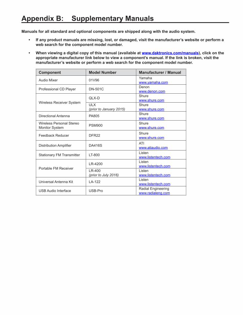
Appendix B: Supplementary ManualsManuals for all standard and optional components are shipped along with the audio system.
• If any product manuals are missing, lost, or damaged, visit the manufacturer’s website or perform a web search for the component model number.
• When viewing a digital copy of this manual (available at www.daktronics.com/manuals), click on the appropriate manufacturer link below to view a component’s manual. If the link is broken, visit the manufacturer’s website or perform a web search for the component model number.
Component Model Number Manufacturer / Manual
Audio Mixer 01V96 Yamahawww.yamaha.com
Professional CD Player DN-501C Denonwww.denon.com
Wireless Receiver SystemQLX-D Shure
www.shure.comULX (prior to January 2015)
Shurewww.shure.com
Directional Antenna PA805 Shurewww.shure.com
Wireless Personal Stereo Monitor System PSM900 Shure
www.shure.com
Feedback Reducer DFR22 Shurewww.shure.com
Distribution Amplifier DA416S ATIwww.atiaudio.com
Stationary FM Transmitter LT-800 Listenwww.listentech.com
Portable FM ReceiverLR-4200 Listen
www.listentech.comLR-400 (prior to July 2016)
Listenwww.listentech.com
Universal Antenna Kit LA-122 Listenwww.listentech.com
USB Audio Interface USB-Pro Radial Engineeringwww.radialeng.com


Appendix C: Daktronics Warranty and Limitation of Liability

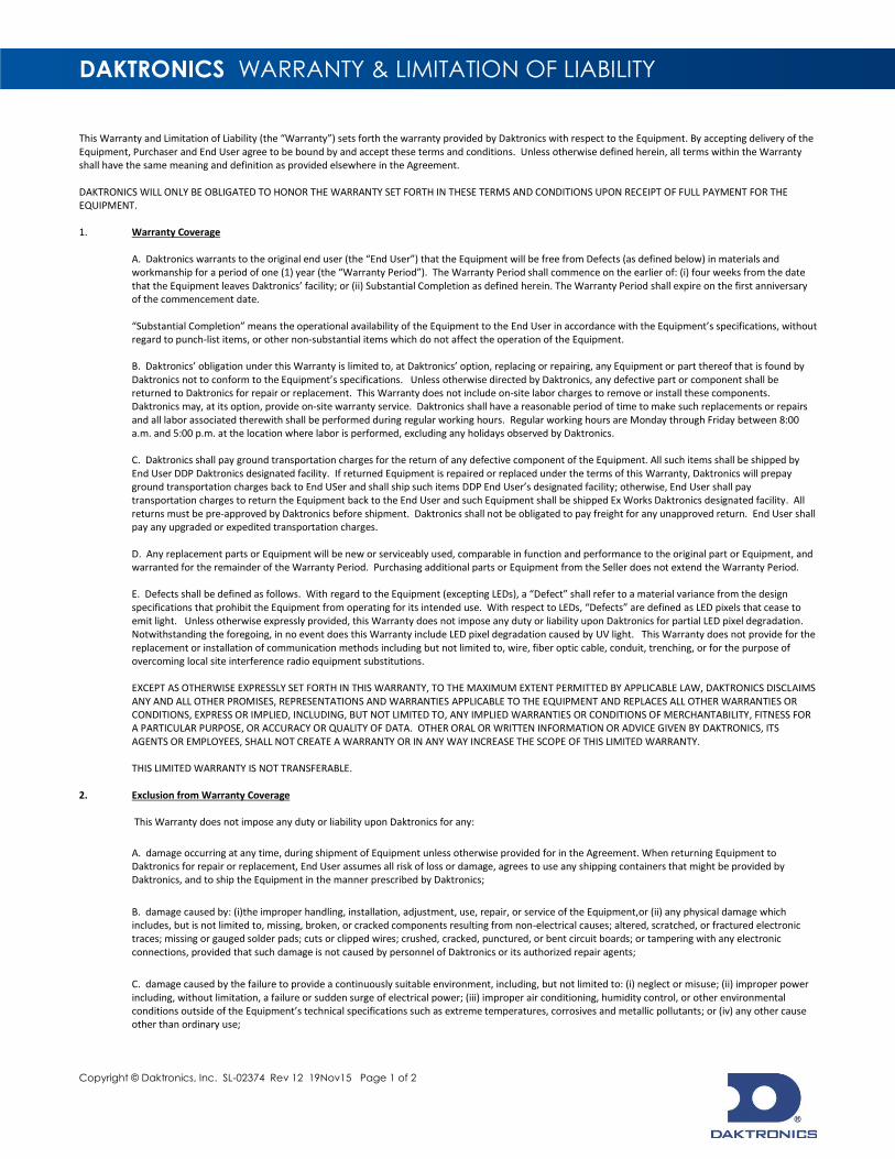
DAKTRONICS WARRANTY & LIMITATION OF LIABILITY
Copyright © Daktronics, Inc. SL-02374 Rev 12 19Nov15 Page 1 of 2
This Warranty and Limitation of Liability (the “Warranty”) sets forth the warranty provided by Daktronics with respect to the Equipment. By accepting delivery of the Equipment, Purchaser and End User agree to be bound by and accept these terms and conditions. Unless otherwise defined herein, all terms within the Warranty shall have the same meaning and definition as provided elsewhere in the Agreement. DAKTRONICS WILL ONLY BE OBLIGATED TO HONOR THE WARRANTY SET FORTH IN THESE TERMS AND CONDITIONS UPON RECEIPT OF FULL PAYMENT FOR THE EQUIPMENT. 1. Warranty Coverage
A. Daktronics warrants to the original end user (the “End User”) that the Equipment will be free from Defects (as defined below) in materials and workmanship for a period of one (1) year (the “Warranty Period”). The Warranty Period shall commence on the earlier of: (i) four weeks from the date that the Equipment leaves Daktronics’ facility; or (ii) Substantial Completion as defined herein. The Warranty Period shall expire on the first anniversary of the commencement date. “Substantial Completion” means the operational availability of the Equipment to the End User in accordance with the Equipment’s specifications, without regard to punch-list items, or other non-substantial items which do not affect the operation of the Equipment.
B. Daktronics’ obligation under this Warranty is limited to, at Daktronics’ option, replacing or repairing, any Equipment or part thereof that is found by Daktronics not to conform to the Equipment’s specifications. Unless otherwise directed by Daktronics, any defective part or component shall be returned to Daktronics for repair or replacement. This Warranty does not include on-site labor charges to remove or install these components. Daktronics may, at its option, provide on-site warranty service. Daktronics shall have a reasonable period of time to make such replacements or repairs and all labor associated therewith shall be performed during regular working hours. Regular working hours are Monday through Friday between 8:00 a.m. and 5:00 p.m. at the location where labor is performed, excluding any holidays observed by Daktronics. C. Daktronics shall pay ground transportation charges for the return of any defective component of the Equipment. All such items shall be shipped by End User DDP Daktronics designated facility. If returned Equipment is repaired or replaced under the terms of this Warranty, Daktronics will prepay ground transportation charges back to End USer and shall ship such items DDP End User’s designated facility; otherwise, End User shall pay transportation charges to return the Equipment back to the End User and such Equipment shall be shipped Ex Works Daktronics designated facility. All returns must be pre-approved by Daktronics before shipment. Daktronics shall not be obligated to pay freight for any unapproved return. End User shall pay any upgraded or expedited transportation charges. D. Any replacement parts or Equipment will be new or serviceably used, comparable in function and performance to the original part or Equipment, and warranted for the remainder of the Warranty Period. Purchasing additional parts or Equipment from the Seller does not extend the Warranty Period. E. Defects shall be defined as follows. With regard to the Equipment (excepting LEDs), a “Defect” shall refer to a material variance from the design specifications that prohibit the Equipment from operating for its intended use. With respect to LEDs, “Defects” are defined as LED pixels that cease to emit light. Unless otherwise expressly provided, this Warranty does not impose any duty or liability upon Daktronics for partial LED pixel degradation. Notwithstanding the foregoing, in no event does this Warranty include LED pixel degradation caused by UV light. This Warranty does not provide for the replacement or installation of communication methods including but not limited to, wire, fiber optic cable, conduit, trenching, or for the purpose of overcoming local site interference radio equipment substitutions. EXCEPT AS OTHERWISE EXPRESSLY SET FORTH IN THIS WARRANTY, TO THE MAXIMUM EXTENT PERMITTED BY APPLICABLE LAW, DAKTRONICS DISCLAIMS ANY AND ALL OTHER PROMISES, REPRESENTATIONS AND WARRANTIES APPLICABLE TO THE EQUIPMENT AND REPLACES ALL OTHER WARRANTIES OR CONDITIONS, EXPRESS OR IMPLIED, INCLUDING, BUT NOT LIMITED TO, ANY IMPLIED WARRANTIES OR CONDITIONS OF MERCHANTABILITY, FITNESS FOR A PARTICULAR PURPOSE, OR ACCURACY OR QUALITY OF DATA. OTHER ORAL OR WRITTEN INFORMATION OR ADVICE GIVEN BY DAKTRONICS, ITS AGENTS OR EMPLOYEES, SHALL NOT CREATE A WARRANTY OR IN ANY WAY INCREASE THE SCOPE OF THIS LIMITED WARRANTY. THIS LIMITED WARRANTY IS NOT TRANSFERABLE.
2. Exclusion from Warranty Coverage
This Warranty does not impose any duty or liability upon Daktronics for any:
A. damage occurring at any time, during shipment of Equipment unless otherwise provided for in the Agreement. When returning Equipment to Daktronics for repair or replacement, End User assumes all risk of loss or damage, agrees to use any shipping containers that might be provided by Daktronics, and to ship the Equipment in the manner prescribed by Daktronics; B. damage caused by: (i)the improper handling, installation, adjustment, use, repair, or service of the Equipment,or (ii) any physical damage which includes, but is not limited to, missing, broken, or cracked components resulting from non-electrical causes; altered, scratched, or fractured electronic traces; missing or gauged solder pads; cuts or clipped wires; crushed, cracked, punctured, or bent circuit boards; or tampering with any electronic connections, provided that such damage is not caused by personnel of Daktronics or its authorized repair agents; C. damage caused by the failure to provide a continuously suitable environment, including, but not limited to: (i) neglect or misuse; (ii) improper power including, without limitation, a failure or sudden surge of electrical power; (iii) improper air conditioning, humidity control, or other environmental conditions outside of the Equipment’s technical specifications such as extreme temperatures, corrosives and metallic pollutants; or (iv) any other cause other than ordinary use;

DAKTRONICS WARRANTY & LIMITATION OF LIABILITY
Copyright © Daktronics, Inc. SL-02374 Rev 12 19Nov15 Page 2 of 2
D. damage caused by fire, flood, earthquake, water, wind, lightning or other natural disaster, strike, inability to obtain materials or utilities, war, terrorism, civil disturbance, or any other cause beyond Daktronics’ reasonable control; E. failure to adjust, repair or replace any item of Equipment if it would be impractical for Daktronics personnel to do so because of connection of the Equipment by mechanical or electrical means to another device not supplied by Daktronics, or the existence of general environmental conditions at the site that pose a danger to Daktronics personnel;
F. statements made about the product by any salesperson, dealer, distributor or agent, unless such statements are in a written document signed by an officer of Daktronics. Such statements as are not included in a signed writing do not constitute warranties, shall not be relied upon by End User and are not part of the contract of sale; G. damage arising from the use of Daktronics products in any application other than the commercial and industrial applications for which they are intended, unless, upon request, such use is specifically approved in writing by Daktronics; H. replenishment of spare parts. In the event the Equipement was purchased with a spare parts package, the parties acknowledge and agree that the spare parts package is designed to exhaust over the life of the Equipment, and as such, the replenishment of the spare parts package is not included in the scope of this Warranty; I. security or functionality of the End User’s network or systems, or anti-virus software updates;
J. performance of preventive maintenance; K. third-party systems and other ancillary equipment, including without limitation front-end video control systems, audio systems, video processors and players, HVAC equipment, batteries and LCD screens; L. incorporation of accessories, attachments, software or other devices not furnished by Daktronics; or M. paint or refinishing the Equipment or furnishing material for this purpose.
3. Limitation of Liability
Daktronics shall be under no obligation to furnish continued service under this Warranty if alterations are made to the Equipment without the prior written approval of Daktronics.
It is specifically agreed that the price of the Equipment is based upon the following limitation of liability. In no event shall Daktronics (including its subsidiaries, affiliates, officers, directors, employees, or agents) be liable for any claims asserting or based on (a) loss of use of the facility or equipment; lost business, revenues, or profits; loss of goodwill; failure or increased cost of operations; loss, damage or corruption of data; loss resulting from system or service failure, malfunction, incompatibility, or breaches in system security; or (b) any special, consequential, incidental or exemplary damages arising out of or in any way connected with the Equipment or otherwise, including but not limited to damages for lost profits, cost of substitute or replacement equipment, down time, injury to property or any damages or sums paid to third parties, even if Daktronics has been advised of the possibility of such damages. The foregoing limitation of liability shall apply whether any claim is based upon principles of contract, tort or statutory duty, principles of indemnity or contribution, or otherwise. In no event shall Daktronics be liable for loss, damage, or injury of any kind or nature arising out of or in connection with this Warranty in excess of the Purchase Price of the Equipment. The End User’s remedy in any dispute under this Warranty shall be ultimately limited to the Purchase Price of the Equipment to the extent the Purchase Price has been paid.
4. Assignment of Rights
The Warranty contained herein extends only to the End User (which may be the Purchaser) of the Equipment and no attempt to extend the Warranty to any subsequent user-transferee of the Equipment shall be valid or enforceable without the express written consent of Daktronics.
5. Governing Law The rights and obligations of the parties under this Warranty shall not be governed by the provisions of the United Nations Convention on Contracts for the International Sales of Goods of 1980. The parties consent to the application of the laws of the State of South Dakota to govern, interpret, and enforce each of the parties’ rights, duties, and obligations arising from, or relating in any manner to, the subject matter of this Warranty, without regard to conflict of law principles.
6. Availability of Extended Service Agreement
For End User’s protection, in addition to that afforded by the warranties set forth herein, End User may purchase extended warranty services to cover the Equipment. The Extended Service Agreement, available from Daktronics, provides for electronic parts repair and/or on-site labor for an extended period from the date of expiration of this warranty. Alternatively, an Extended Service Agreement may be purchased in conjunction with this Warranty for extended additional services. For further information, contact Daktronics Customer Service at 1-800-DAKTRONics (1-800-325-8766).