" $300 - World Radio History
96
SME FOR TECHNICAL AND ENGINEERING MANAGEMENT AN ACT III PUBLICATION MARCH 1989 " $300 RECOMMENDATIONS ON AUDIO FOR THE VISUAL MEDIUM n. Le..: ti . e ' .. '.1 " 40 .. >$. " c..3. ' .a. It q 1 -. . .t, .e- . . e . e - 10%.. oe .. *C '* f; v.. * e It.eit - . . .24. yy y ..-44 *. a a ' . - a ; *4. .a L '4. .P ? ; ;* ,.".' :11 a F cu:k4!....,. '
-
Upload
khangminh22 -
Category
Documents
-
view
0 -
download
0
Transcript of " $300 - World Radio History

SMEFOR TECHNICAL AND ENGINEERING MANAGEMENT
AN ACT III PUBLICATION MARCH 1989 " $300
RECOMMENDATIONS ONAUDIO FOR THEVISUAL MEDIUM
n.
Le..:
ti . e ' .. '.1 " 40 ..
>$. " c..3. ' .a.It q 1 -. . .t, .e-. . e .
e - 10%.. oe.. *C '*
f;v.. *
eIt.eit
- . ..24. yy
y ..-44 *. a a ' .- a ; *4..a
L'4. .P
? ;;* ,.".':11 a
F
cu:k4!....,.
'

WHY DIDN'T SOMEONE THINK 0THIS BEFORE?
A FAST -PACED PRODUCTION CONSOLE
THE WHEATSTONE SP -6 AUDIO CONSOLElets production people quickly accomplish
8 and 16 -track work, yet easily handle routinetransfers and dubbing operations. With itsunique track monitor section it can facilitatesimultaneous stereo mixdown during the multi-track bed session - almost halving typical pro-duction time cycles. Input channels are laid outJust like an air console, with machine startsbelow the channel fader, so staff familiar withon -air consoles can quickly become comfort-able in the production environment.
For those interested in more advanced tech-niques, the SP -6 employs a powerful talentmonitor section designed to rapidly call up livemic and track combinations, making difficultpunch -ins a breeze. Standard SP -6 input chan-nel equalizers are more comprehensive than
those supplied as optional items on compet-ing products, allowing much greater creativefreedom. Input channel auxiliary send sectionsare designed to be the most versatile in theindustry, providing 4 different auxiliary buses toallow digital delay, reverb, talent foldback, andmix -minus feeds. Stereo input channels canprovide either mono or stereo effects sends.Even more, the SP -6 has 4 auxiliary effectsreturn inputs that allow effects to be recordedonto the multitrack or sent to the monitor buses.
%At
The SP -6 provides independent headphonecontrol room and studio monitor feeds, as welas stereo cue/solo. Control room and studimute and tally functions are independentldipswitch selectable on individual input channels. Additional studio modules may be ordereto accommodate larger, multi -studio installsLions. The SP -6 may be configured with ancombination of mono and stereo input mod-ules, in mainframe sizes ranging from 16 t32 or more inputs. The console is availablein either an 8 -track production format or a 4stereo subgroup TV master control configura-tion. So why not profit from Wheatstone'sexperience and reputation? Call us today andlearn more.
re'--''-iri-1PY-
----3.4-- -
-.'1"--;-----------
---:.7ihiW'
'rtrc . __' . .
Pr
-P.r.. t-..t-.-PP-''-to-_______._.._..4._____1__________/1hpi -t--I-
. ... lir`....---- ),- tril.-' Y.--,...,,..... , , Prob. ' ----_____
---*7 l' 'P:b! -'.-,... - I' &---.._ ,
..... slk,.. Pr p.,.
kil..t2,-.
' av,
' Z.
4 4-... t"+" ',e...
khaL l
4 4
16.4
NVVheotrton Cor oration
--=---_-;-
_ .
-L
-
"-I:-
V.I.P.P oy,Circle 100 on Reader Service Card Page 63
TEL 315 -455 -7740 -FAX 315-454-8104

Over thirty years of large capability RFtransmission line installations .... proven world wide.
iramigimP!
11 the early 1950's we developed the word'sf rst semi -flexible RF coaxial cables with arevolutionary new technique of seam weldedcorrugated construction. This new type ofcable fabrication offered not only flexibility,strength and improved electrical benefits outalso considerable advantages in the transporta-tion and installation of long runs of RFtransmission lines. By 1961 we again were thefirst with the development and manufactwe ofcorrugated elliptical waveguide. Today seamwelded corrugated RF transmission lines areknown by the trade name Flexwell and are
produced and marketed worldwide bymember companies of the international RadioFrequency Systems Group.
For more nformation on the Flexwell familyof RF transmission lines, contact CablewaveSystems div'sion Df Radio Frequency SystemsInc. North America. 60 Dodge Avenue, NorthHaven, CT 06473 (203) 239-3311.
Cablewave Systems
Circle 101 on Reader Service Card Page 53
And only one number to call. For more information on Sony's latest innovations in its line of quality

MON.
FOR,
i 641:+bie 1111111111111111111
1111111111111111w
MINEIMOMMEEMBEIMBIZM
CHOOSE.MONITOR
monitors, dial (800) 523 -SONY. S CO Sony Communications Products Company, 1600 QueenAnne Road, Teaneck, NJ 07666. ©1989 Sony Corporationof America. Sony is a trademark of Sony.
PROFESSIONAL VIDEOCircle 102 on Reader Service Card Page 63

Big FX.
Small Package.,
-0"
ranm III.
ft -Oh OFT:1 ,
-
L A -Cy- ,11111MILtlf3ir "185 Eiraziaj,vlI ?"'
A C E
If fitting all this capability into sucha remarkably compact switcheris a piece of cake, everyoneshould be offering you one.
They aren't.
Not with true linear keying viadual linear keyers... standard.
To assure compatability with anti-aliased graphic systems.These switchers would also offer over 80 wipe patterns.Including rotary and clock wipes. As well as dualpattern generators for wipe within wipe effects, a non-volatile fx memory with 64 set-up capability, and toomuch more to list in this ad.
1111117 WTI
1111" 111
And if that kind of compact capability is as hard toachieve as it seems to be, the T8 should cost a bundle.
It doesn't.
Which should mean the T8 is going to sell like theproverbial hot cakes.
It already has.
Maybe you should giveyour Midwest representa-tive a little call.
To get the big picture onthe T8.
Circle 103 on Reader Service Card Page 63
MIDIVISTCommunications Corp.
One Sperti DriveEdgewood, KY 41017
(606) 331-8990
the0 RC

BMW
On the cover:"CAVEAT:
White Paper II,"cover illustrationby Tom Cushwa.
41 Dial -Up R-ENG
BMEFOR TECHNICAL AND ENGINEERING MANAGEMENT
MARCH 1989VOL. 25, NO. 3
Features
28 Public PerfectionDespite its reputation for high -quality production,WGBH hadn't upgraded its routing facilities sincethe early 1960s. A new rebuild has propelled thestation into the 1990s and beyond.
33 CAVEAT: White Paper II-Recommendations on Audio for theVisual MediumA BME exclusive: Full printing of the Chicago,Chapter of the ITS's white paper suggestions forstandardization of audio for video.
37 Radio Engineering
38 Radio NewsRDS Radio Comes On -Stream in Europe....NewRecording Instruction Videotapes....MIT ProfessorSlams FM Stereo, FMX
41 Improved R-ENG Using Dial -Up LinesThe economics of R-ENG and other radio remoteshave changed dramatically since the AT&T divesti-ture. Using frequency shifters to improve the fidel-ity of dial -up lines can save time, money and audioquality.
47 Designing Efficient Medium -WaveTransmittersRF efficiency is an important component of cost-ef-fective station operation. Digital modulation tech-niques can improve operating efficiency by one-third.
28 WGBH: PBS FlagshipBME March 1989 7

DESIGNED FOR RADIO BY PEOPLE WHO KNOW RADIO...
MIX TRAK 9ON -AIR CONSOLE
Unlike other consoles that try to be all things forall applications, the new Mix Trak 90 modular consolefrom Broadcast Electronics is strictly designed foron -air use!
Mix Trak 90 features include: Split Program Buss Three Telephone Mix -Minus Busses Balanced Patch Points Throughout On -card Voltage Regulation Transformerless Inputs and Outputs
Another Mix Trak 90 value feature is the optionalSource Sequencer. The Source Sequencer permitsyour on -air talent to automatically execute an entireseries of events (such as a multi -spot commercial
TM
break) with the touch of a single switch. When theSource Sequencer is at work, your DJ's are free toconcentrate on what they do best: communicate!
The Mix Trak 90 offers full VCA gain control, Penny& Giles precision faders, independent Audition andProgram metering, silent Hall Effect switching,automatic monitor dimming for easier cueing anda wide range of accessory modules.
For more information about the new consoledesigned with your special needs in mind contactyour Broadcast Electronics Representative orcall Bob Arnold at 217-224-9600.
Circlle 104 on Reader Service Card Page 63
=EO
BROADCASTELECTRONICS INC.
4100 N. 24th ST., P.O. BOX 3606, QUINCY, IL 62305, (217) 224-9600, TELEX: 250142, FAX: (217) 224-9607

EGroup Publisher
KEVIN J. CONDON
PublisherMICHAEL D. BAILENSON
EditorEVA J. BLINDER
Senior EditorBETH JACQUES
Technical EditorJAMES A. ACKERLEY
Managing EditorMICHAEL D. ESPINDLE
Copy EditorPATRICK D. O'NEILL
Contributing EditorSKIP PIZZI
Art DirectorDONALD H. KROGMAN
Production DirectorNICK TARTAGLIA
Assistant Production ManagerMARGOT SUYDAM
Associate PublisherPATRICK J. MOLONEY
Northern District Sales ManagerWILLIAM P. DEY
Western District Sales ManagerDENICE NICHOLS
ControllerJOSEPH M. PANNULLO
Circulation ManagerJOSEPH SCHILLMOELLER
Executive AssistantSHARON PORGES
Act III Publishing
PresidentPAUL DAVID SCHAEFFER
Senior Vice President,Technical Division
KEVIN J. CONDON
Senior Vice President,Corporate Development & Planning
MARTHA LORINI
Senior Vice President, CorporatePlanning & International Development
GERARD A. BYRNE
Vice President,Finance & Administration
SAM SCHECTER
Act III Publishing, Technical Division295 Madison Ave., New York. NY 10017
(212) 685-5320 Telex: 64-4001Fax: (212) 679-0919Also publishers of:
World Broadcast NewsCorporate Video Decisions
is publishedinc.pu BMEblishedMP imMonEthlyI by NBB 2°NBB A5cq-3uislit)io
A is circulated without charge to those re-r" sponsible for station operation and forspecifying and authorizing the purchase of equipmentused in broadcast facilities in the U.S. and Canada.These facilities include AM, FM and TV broadcast sta-tions. CATV systems, ETV stations, networks and stu-dios, audio and video recording studios. teleproductionfacilities, consultants, etc. Subscription prices to oth-ers: $36.00 one year, $50.00 two years. Foreign: $50.00one year, $75.00 two years. Air Mail rates on request.Copyright 1989 by NBB Acquisitions. Inc.. New YorkCity. Second class postage paid New York. NY. andadditional mailing offices.
POSTMASTER: send address changes to BME, P.O.Box 6056, Duluth. MN 55806.
Columns & Departments
11 ViewpointBehind the White Paper
13 UpdateABC HDTV Standard Appeal Denied....BME GetsNew Publisher....NOAA Weather Satellite GoesDead....Paltex Acquires EECOIConuergence....FCC,Broadcasters Battle EPA for RF RadiationStandards
21 Crosstalk: An EngineeringManagement JournalSBE Holds Mid -Winter Forum...TowerTumbles...Hi-Def for the Masses?
26 Tech Watch'Digital Paper- Sets New Storage Standard
67 ComputeMonitoring Point Vector Analysis for DirectionalAntennas
70 Spectrum: The RegulatoryEnvironmentHow to Go Dark
72 New EquipmentNeumann's New Mw Series...Desktop Audio fromSonic Solutions...ICI Digital Paper...Sony InfraredCamera..And More New Products
80 Business BriefsAES honors Per V. Bruel
81 Advertisers Index
82 Currents: A GuestEditorialState -of -the -Month: TheChallenge of StayingCurrent
13 GOES -6 Goes Dead
BME March 1989 9

No dropoutsTape dropouts mean trouble
for videotape professionals.No wonder so many of themchoose to work with SonyProfessional Videotape. Including the producersof two recent documentaries shot in Russia,who minimized dropouts by shooting withSony Videocassettes.
Sony cassettes were never at a loss forpicture, whether covering sub -zero,Northern Riissia nights or getting impromptuinterviews with people on the street inMoscow.
Not that this surprises those of us at Sony ProfessionalVideotape. After all, we've designed all our productsaround one basic premise: durability. To be frank, thedemanding shooting conditions of Russia aren't as toughon our tape as we are.
in XBR U-matic' cassettes, forinstance, feature a molded -inussia, anti -static cassette shell and
IF components to reduce transientdropout potential by neutralizing staticcharges. Combine this with base film that'sbeen given Sony's exclusive Carbonmirror""back coating and dropout potential isreduced even further.
No matter which Sony Professional Video-tape you're working with, there's one thingyou know for sure. Its greatest ability isdurability. Whether it's U-matic, Betacam,
1" or Digital tape. So take on the world. With SonyVideotape. On location in Moscow, Russia or in astudio in Moscow, Idaho, you need a tape that's toughas Sony. After all, there's no better SONYway to lower the dropout rate.
THE ONE AND ONLY.1988 Sony Corporation of America, Sony, Betacam, U-matic, Carbonmirror and The One and Only are trademarks of Sony.
Circle 105 on Reader Service Card Page 63

In the six years thathave elapsed since
the publication of theoriginal White Paper,
audio for video hasundergone an
amazingtransformation.
VIEWPOINT
few months ago, members of the Chicago chapter of the Inter-national Teleproduction Society approached BME with an unusual request: topublish a greatly expanded and updated version of the White Paper on Audiofor the Visual Medium. We were interested, not only because of the obviousvalue of the work itself, but because of the opportunity it afforded to serve anoften -neglected segment of our industry, the teleproduction engineers.
The original 1982 paper, a four -page pamphlet developed by a group knownas the "Chicago Coalition," already had proven beneficial by encouraginggreater program interchangeability and cooperation among video and audiofacilities. In the six years that have elapsed since the publication of the originalWhite Paper, however, audio for video has undergone an amazing transforma-tion. While many audio -conscious video engineers were producing stereosoundtracks even in 1982, the advent of multichannel television sound has _made stereo production standard operating procedure. Digital audio has movedbeyond the high -end recording studio and into television facilities with thedevelopment of digital VTRs. The evolution of entirely new equipment catego-ries, such as random-access digital audio workstations, has changed the audiopicture profoundly.
It is our great pleasure and honor, therefore, to present White Paper II-in itsfull, unabridged form-in this month's BME. The Chicago Coalition, nowknown as C.A.V.E.A.T. (for Concerned Audio and Video Engineers and Techni-cians), has produced a handbook that should prove a valuable addition to thelibrary of engineers around the country.
The recommendations of the C.A.V.E.A.T. committee, while designed to fos-ter cooperation among facilities, are careful to leave facilities' own proceduresand processes untouched. They deal strictly with ways to streamline the inter-change of audio program material. We feel that their suggestions will be of useto teleproduction facilities everywhere, and also to television station engineersmaking their way through the maze of improved audio.
We're proud to have this opportunity to serve the industry by publishing theC.A.V.E.A.T. White Paper II. Our hats go off to the authors, who overcamecompetition and professional differences to produce a guide that will provebeneficial to the entire industry.
Eva J. BlinderEditor
BME March 1989 11

ONE SMALL STEP FOR SONY.For Sony, it's a small addi-
tion to the world's finest line ofbroadcast cameras. But itmeans a long jump for EFP.
With the new CCU -355Control Unit, you can have thefreedom of triax while using
the best broadcast portableCCD cameras in the world-the Sony BVP-7 and BVP-50.
Sony has offered leading-
edge CCD broadcast cameratechnology for over two years,bringing you the reliability
and consistent picture qualityyou expect from Sony -plusthe portability and freedomof triax.
No one else sells as manybroadcast cameras as Sony.And it's hardly surprising-

ONE GIANT LEAP FOR EFP.considering the broad rangeof leading edge productsSony offers.
So take the plunge into theinherent reliability and stabil-ity of solid state technology.Check into the Sony broadcast
portable CCD camera family:the BVP-5, BVP-7 and BVP-50.And the BVW-200 single -unit
SONY
camera-recorder. The first stepis a demonstration. Just con-tact your Sony BroadcastSales Engineer. Or call us at(800) 635 -SONY.Sony Communications Products Company. 1600 QueenAnne Road. Teaneck, NJ 07666. 1988 Sony Corporationof America. Sony is a registered trademark of Son),
BROADCAST PRODUCTS

Get the complete pictureon your picture.
Leader's new 5854 Battery -PoweredVectorscope is small and light enough tomonitor and phase cameras anywhere...even places your EFP/ENG van can't go.It provides all the important capabilities ofhalf -rack mount vectorscopes. View andtrigger from either of two loop -throughinputs. There's variable gain control.And it reads Differential Gain ±1%while Differential Phase is ±
Carry a test system fromyour shoulder.
And, you can take along other confi-dence builders as well. Like Leader's
equally portable and versatile LBO -5864EFP Waveform Monitor. You can alsoget the waveform monitor with Leader'smatching Portable Color Picture/AudioMonitor. And, as a separate component,an NTSC Pattern Generator with sourceidentification. All use any 12 Vdc source.
In the hand or in the van.Because this is a configurable system,
you can use each unit alone, in selected2 or 3 -unit combinations, or rack mounted.A convenient 2 -unit carrying case evenincorporates a single 12 V battery pack.You get maximum total -studio convenience
111111:10t
The smallestvectorscopeever built.
in a minimum of space, whether station-ary or mobile.
Whatever you need, look at Leaderand see the difference. Backed by aTWO-YEAR WARRANTY and factoryservice depots on both coasts.
Phone now for our catalog, an evalua-tion unit, and the name of your nearest"Select" Leader Distributor.
Call toll -free
1 800 645-51045 16
In2N3Y1
State0 0
Leader Instruments Corporation380 Oser Avenue, Hauppauge, New York 11788
Regional Offices:Chicago, Dallas, Los Angeles, Boston, AtlantaIn Canada call Omnitronix Ltd. 416 828-6221
LEADERSEE LEADER INSTRUMENTS AT THE NAB SHOW,
BOOTHS 5371-5374
FOR PROFESSIONALS WHO KNOWTHE DIFFERENCE
Circle 106 on Reader Service Card Page 63 for DemonstrationCircle 107 on Reader Service Card Page 63 for Literature

UPDATE
ABC HDTV Standard Appeal Denied....BME Gets NewPublisher....NOAA Weather Satellite Goes Dead....
Paltex Acquires EECO/Convergence....FCC, Broadcasters Battle EPA for RF Radiation Standards
ABC HDTV Standard Appeal Deniedhe American National Standards Institute(ANSI) has denied an appeal filed by CapitolCities/ABC Television to revoke SMPTE 240Mas an American standard for high definitionvideo production. SMPTE standard 240M coversthe 1125 line/60 Hz format. The appeal was filed
October 14, 1988 and rejected February 2, 1989. SMPTEand ANSI standards are voluntary and nonexclusive.
Documentation filed by ABC stated that 240M shouldbe a SMPTE standard but not an American nationalstandard. The companysaid that 240M did notmeet essential industrycriteria. Its three com-plaints were that thestandard "did not achieveindustry consensus," thatit "was not suitable for na-tional use", and that "therequirements of due pro-cess were not satisfied in "No stature!"-Cap Cities/ABCthe procedures followedby SMPTE inpromulgating the standard."
"It's interesting that a broadcast corporation appealeda standard for high definition production," added one ex-ecutive who asked to remain anonymous. 240M was de-clared an ANSI standard in August 1988. Initial workin SMPTE committee began in 1983. Industry sourcessay ABC was eligible to participate in working groupsand meetings but did not do so.
"We don't have any problem with 240M as a SMPTE-recommended practice," said Tony Uyttendaele, directorof allocations and rf systems for Cap Cities/ABC. "Wejust don't think it should have the stature of a U.S. na-tional standard. In our opinion, it doesn't deserve that."ABC had "not been very involved" in the standards -making process, according to the BO&E office.
"ANSI had accepted 240M as an accredited Americanproduction standard. The fact that there was an appealat all is out -of -the -ordinary," said Alec Shapiro, coordi-nator for the Washington, DC -based 1125/60 Group.
"We find this very difficult to understand becausefrankly if anything went through due process, this was
I
1125/GROUP
it," Shapiro said. Two hundred and sixty-seven engi-neers participated in creating 240M over a five year pe-riod, he added. The 1125/60 Group is a consortium ofmanufacturers whose goals include promoting imple-mentation of the 1125/60 format as an HDTV video pro-duction standard worldwide.
SMPTE is the official certifying body for ANSI. TheSociety would say only that it approved the format as astandard and was therefore able to submit it to ANSI.Appeals of ANSI standardization are relatively commonin some industries-notably the computer industry-butthey are rare in the broadcast, film and video industries.
NOM WeatherSatellite GoesDeadThe failure on January 21of the GOES -6 weathersatellite which transmit-ted pictures of cloud coverover the Pacific and West-ern UnitedStates caused atemporary par-tial interruptionof service to tele-vision weatherforecasters. Fail-ure was due tothe unavoidablewearing out ofscanning lampsused in the sat-ellite to activatethe TV imagingprocess.
According to astatement issuedby the NationalOceanic and At-mospheric Ad-
ministration (NOAA), thesatellite was launched onApril 28, 1983 with a lifeexpectancy of five years.Actual life was extendednine months beyond expec-tations by shutting downthe TV imaging processduring periods when nopictures were needed, thus
The GOES -6 weather information satellite.
BME March 1989 15
Wouldn't it be great ifsomebody built a routingswitcher that could handleALL of your switchingrequirements today with-out becoming obsoletetomorrow?
SOMEBODY DOES.UTAH SCIENTIFIC.
Utah Scientific routing systems perform to the best specsin the industry. Reliability, ease of operation and long-term stability have been proven in more than 500 instal-lations around the world.
Whether you need a simple 10x10 audio/video router, ora large, multi -level matrix to handle timecode, tally, andRS -422 control switching, Utah Scientific can provide arouter configuration to meet your needs.
Controlling the router is easy with the industry's broadestselection of control panels, computer interface equipment,and automatic control systems, all of which are user repro-grammable. And, the uniquely flexible design of the UtahScientific system ensures that you will have a router whichcan be easily expanded as your systems requirementschange.
Call us today for more information.
LITF?/-1sciEr7TIFIC
Circle 108 on Reader Service Card Page 63
DYNATECH Broadcast Group1685 West 2200 South, Salt Lake City, Utah 84119(801) 973-6840 Toll -Free: 1-800-453-8782

extending the life of thescanning lamps. NOAAwill launch a replacementsatellite in mid -1990 con-taining light emitting di-odes (LEDs) which will beused to supplement andextend the life of the stan-dard scanning lamp ele-ments on the satellite.
In the meantime, a sur-viving satellite, GOES -7,will be moved from itspresent position at 79.5degrees west longitude toa new position at 108 de-grees west longitudewhere it will cover the en-tire country plus majorportions of both the Atlan-tic and Pacific. In thespring, the remaining sat-ellite will be moved back10 degrees to watch forAtlantic hurricanes andnext fall it will be movedwestward again to watchfor western winter storms.
Major suppliers of satel-lite weather imaging and
UPDATE
data to the television in-dustry report only minorinconveniences, if any, totheir customers. GeorgeCares, senior meteorolo-gist for Weather ServiceInternational (WSI) says,"We have not been af-fected by the loss ofGOES -6 and if the plan toreposition GOES -7 pro-ceeds smoothly, there
should be no interruptionof service."
Jim Menard, manager ofsystem operations forEnvironmental SatelliteData (ESD) reports, "Serv-ice to Hawaii was lost al-together and the WesternStates experienced a one-half -hour delay in servicewhile our computerswitched over to receiving
data from the GOES -East(GOES -7) satellite only.As the GOES -East isrepositioned, storms nor-mally picked up over Af-rica will be picked up overthe Atlantic. In order tocompensate, we plan tosupplement GOES -Eastcoverage with data fromthe European Meteosatand others."
11111F -- -"1=1111111111111=111111111111111111111111111111111111111111111111111111
FCC,BroadcastersBathe EPA forRF RadiationStandardsThe FCC, NAB and theElectromagnetic EnergyPolicy Alliance (EEPA)are pulling out all thestops to induce the Envi-ronmental ProtectionAgency (EPA) to recon-
1.1.101kBME Gets New Publisher
ct III Publishing (Technical Division) has namedMichael D. Bailenson the new publisher of Mg
ME. Bailenson joins Act III from Intertec,where he was most recently publisher of ElectricalConstruction Technology.
"Michael is a real pro andhis enthusiasm and energy,"said Kevin Condon, grouppublisher for Act III's tech-nical publishing division.Condon continues as grouppublisher and Pat Moloneycontinues as associate pub-lisher for BME.
Bailenson, once also withLebhar-Friedman, is marriedand lives in New York City.
we look forward to
sider its decision to dropwork on the establishmentof radiofrequency (rf) radi-ation guidelines. The EPAmade its decision to stopwork last fall in responseto budgetary consider-ations and the need to fo-cus limited resources onselected issues, accordingto an EPA statement.
Ralph Justus, NAB di-rector of engineering forregulatory and interna-tional affairs, explainedthe danger by saying, "Inthe absence of federalstandards, localities willadopt a patchwork of localregulations not based onscientific fact that ad-versely affect broadcasterswith no clear offsettingpublic benefit.
"Scientific literature isuncertain of preciselywhere and under whatconditions rf radiation con-stitutes a hazard tohumans, but standards ofsafety such as have beenadopted by the AmericanNational Standards Insti-tute (ANSI) can be estab-lished on the basis of sci-entific best guesses."
FCC chairman DennisR. Patrick, in a letter lastNovember to EPA admin-istrator Lee M. Thomas,
requested that the EPAreview its decision to deferthe rf radiation programand stated, "In manycases, the lack of federalstandards has already ledlocal officials to favor sig-nificant restrictions on rftransmitters that are notsupported by scientific evi-dence and that can delayand disrupt telecommuni-cations services."
Patrick also noted thatconsiderable progress hadalready been made in theresearch and that re-estab-lishing the effort at a laterdate would be difficult andtime-consuming.
The EEPA, whose boardof directors represents theNAB and such industrialgiants as GTE, GE, SRI,Rockwell, NBC, Raytheon,Motorola and AT&T, isadding its weight to thestruggle. In his Novemberletter to the EPA'sThomas, EEPA presidentJay J. Brandinger wrote,"Failure to use the com-paratively few manhoursnow needed to completethe electromagnetic guid-ance document constitutesunconscionable waste."
In a January reply toPatrick, EPA assistant ad-ministrator Don R. Clay
BME March 1989 17

UNWANTED FRAMEGRABBING STOPS HERE
STATLE
EXTERNAL REFERENCEHIE 5E10 LOCK. SI ASS
INFO VIDEO
5E10 CAL IMPUI LEV, CUROYACI=
DFS-3000N Digital Frame Synchronizer
If your video synchronizer lets youdown on a noisy feed, you need the
new Leitch DFS-3000N. This digitalframe synchronizer incorporates inputprocessing circuitry that uses the latestin digital auto -correlation techniques toprevent intermittent frame grabbing orswitching to black. Only Leitch offersthis capability.
LEITCH
°WPM' PEASE;PI DFS-MOON
DIGITAL FRAMEsyNctin SNITER
Now you know one of the features of theLeitch DFS-3000N. But the advantagesdon't stop there. Neither should you.Write or call (toll free) for furtherinformation.
In U.S.A. 1.800-231-9673In Canada 1-800-387-0233
Leitch Video of America, Inc.825k Greenbrier CircleChesapeake, VA 23320(804) 424-7920
Leitch Video International Inc.10 Dyas Road, Don MillsOntario, Canada M3B 1V5(416) 445-9640
Progressive Concepts in Television TechnologyCircle 109 on Reader Service Card Page 63

wrote, "At this time I donot think we will be ableto go forward with the rule -making procedures." Can-cer fears were expressedby Norton Nelson, chair-man of the Executive Com-mittee of the Science Advi-sory Board of the EPA, inhis July letter to adminis-trator Thomas. Nelson said,in part, "The agency mustnot totally abandon itswork in the area of non -ionizing radiation. Thisrecommendation is par-ticularly relevant in thelight of two studies deal-ing with non -ionizing radi-ation reported in the cur-rent issue of the AmericanJournal of Epidemiology,which evidence both thecontinuing interest in thisfield and the ambiguous na-ture of most current data."
Last July in Massachu-setts, the lack of federalstandards led local offi-cials to put into force theirown non -ionizing radiation
UPDATE
law. Huck Hodgkins, pres-ident of WBRK-AM inPittsfield, MA said, "Iwould support the NABposition in regard to theneed for a federal rf radia-tion standard. As far asthe present law is con-cerned, I don't know ofanyone who had troublewith the inspection, butyou do have to go off theair to perform any mainte-nance on the antenna."
Marc Peters, chief engi-neer of WHRB-FM, Cam-bridge, MA, said a na-tional standard isnecessary. "The FCC iscorrect, a more compre-hensive national standardis best," Peters said. "Acity law, for instance,would not affect the areaoutside the city limits, butthis might be the veryplace the station has itsantenna. The EPA or theFCC should set the stan-dards which would then beavailable to all cities."
CAUTIONHIGH LEVEL
RADIO FREQUENCY ENERGY AREA
NO TRESPASSING
Paltex Acquires EE CO/Convergence
With the major acquisition of EECO/Convergence, Paltex International hasgained a leading share of the market in vid-
eotape editors, joining such giants as Ampex, CMX,Sony and Grass Valley. The sale involves onlyEECO's video editing business which EECO acquiredtwo and a half years ago when it took over Conver-gence. In a January 20 statement, EECO explainedthat divestiture of this and other business units willpermit it to concentrate on its core business of manu-facturing electro-mechanical switches, computer key-boards, membrane keyboards and avionics products.
Sale of the video editing business, which has beenunprofitable, will result in a $7.7 million one-timepre-tax loss. Also on the block are the company's ho-tel computer property management subsidiary and itseighteen -acre Santa Ana, CA, headquarters. Thesetransactions, when completed, will allow EECO to re-alize substantial cash proceeds. Operating losses areexpected to continue through the fourth quarter.
Industry reaction to the takeover has beenguarded. Ampex public relations manager DaveDetmers said, "The acquisition is indicative of someof the changes taking place in the industry." Users ofConvergence products also took a wait and see atti-tude. Eliot Reed, director of ENG operations at ABC(which uses several Convergence units) commented,"Time will tell how Paltex continues the Convergenceline and how they will deal with the network."
Paltex has assured owners of Convergence equip-ment that the newly reformed Convergence Corp. willassume all customer service activities, providing fullsystem and software support, and that Convergenceediting systems will continue to be represented bythe current distributors.
In the scant ten years of its existence, Paltexclaims to have become the largest independent manu-facturer of video systems in the world. The companywill manufacture all products in Tustin, CA.
In looking to the future, Roger Bailey, chairmanand managing director, stated, "We will certainly notdrop any product and in the long term hope to addnew lines. At the sustaining level, we have alreadyintegrated manufacturing and engineering and wealso intend to integrate R&D. Convergence productswill continue to be marketed under the Convergencename, including the IVES and EMME editors whichwere originally EECO products."
BME March 1989 19

Designed for production quality...With an eye on your budget.
Panasonic presents two very versatile, high-gradecolor monitors --the BT-D191OY and the BT-M1310Y. Builtfor performance, these BT -Series monitors offer you thequality and reliability you've come to expect from Pana-sonic. Not to mention a wide array of features at an af-fordable price.
Our BT -Series provides you with the controls andconnections necessary for studio applications --whileserving a host of industrial, educational and professionalvideo needs.
For maximum performance and versatility, both moni-tors offer complete, direct compatibility with the newS -VHS format --in addition to conventional signals. Andvideo reproduction on the BT -Series is superb. As amatter of fact, the BT-M1310Y boasts a horizontal reso-lution of more than 560 lines, while the BT-D1910Y offersyou greater than 550 lines.
SVHSWhat's more, each monitor provides you with a full set
of front panel controls. Like Line A/B split, S -Video inputconnectors, Blue signal -only switch, pulse -cross circuit,preset picture off/on, comb/trap filter selectable and nor-mal/underscan switch, just to name a few.
So when you are looking for professional quality, butstill need to keep an eye on your budget, look into thePanasonic BT -Series high-grade monitors. For more in-formation, call Panasonic Industrial Company at 1-800-553-7222. Or contact your local Panasonic Professional/Industrial Video Dealer.
PanasonicProfessional/Industrial Video
Circle 110 on Reader Service Card Page 63

CROSSTALKAN ENGINEERING MANAGEMENT JOURNAL
SBE Holds Mid -Winter Forum....TowerTumbles....Hi-Def for the Masses?
SBE Holds Mid -Winter Forum
everal issues of interest to thebroadcast community were dis-cussed at a forum held by the So-
ciety of Broadcast Engineers in Wash-ington, DC on January 11, 1989.Panelists were Lex Felker of theFCC's Mass Media Bureau, WallaceE. Johnson of the consulting firmMoffet, Larson and Johnson, and Mi-chael Rau of NAB's Science and Tech-nology Division. Bob Van Buhler,SBE executive VP, chaired the panel.
Felker listed the major items cur-rently in motion at the FCC, whichincluded AM interference, the ex-tended AM band, FM class -of -serviceupgrades, movement toward contourassignment methodology for FM, andhigh definition television broadcaststandardization. On HDTV, Felkersaid the Commission will rely heavilyon the recently formed AdvancedTelevision Test Center for its data,praising the ATTC as a great exampleof private sector cooperation. A finaldecision on the National Radio Stan-dards Committee (NRSC) AM recom-mendations will be made in early1989, according to Felker.
Wally Johnson, who also serves asexecutive director of the Associationfor Broadcast Engineering Standards(ABES), raised concerns about trendsin recent broadcast regulation that hefelt seemed to protect the entrepre-neurial interests of broadcasters atthe expense of the public good. Hequestioned the current validity of theFCC's traditional notion that inter-ference should only be dealt with ifsufficient public complaints arereceived.
"Those days are long gone," saidJohnson. "With so many choices to-day, the audience just tunes else-
where if interference is noted. Yet aservice is lost." He exhorted the Com-mission to avoid making allocations"with Vaseline and shoehorns," andurged them to continue updatingtheir calculation methods.
Mike Rau voiced the NAB's interestin pending FM directional antenna(DA) regulation. He expressed sup-port for proposed FM contour -protec-tion allocation methods, similar tothose currently inuse for AM. Raualso announcedthat the SBE andNAB will jointlysponsor a series ofUplink Seminarsfor broadcast earthstation personnel.The five-dayevents will be heldat various loca-tions and accept 20attendees on afirst -come, first -served basis. Sem-inar content willstress safety andinterference man-agement in alltypes of uplinkhardware, C band and Ku, fixed andportable. One day of hands-on with aportable uplink will be included. Con-tact Janet Elliott at the NAB for fur-ther information at (202) 429-5346.
SBE personnel reported that theSociety's search for an executive di-rector and the consideration of a pos-sible HQ move from St. Louis, MO toWashington, DC are both still under-way. The SBE's engineer certificationprogram continues to gain momen-tum, according to the society. Moreclassified ads mentioning the certi-fication as a criterion for employment
are appearing, the SBE notes. In addi-tion, the Broadcast Education Associ-ation has approached the SBE to dis-cuss the possibility of establishing anoperator's -class certification, approxi-mating the function of the old FCCThird -Class license. A survey of sta-tion managers is under developmentto determine whether this is a worth-while undertaking. Meanwhile, theSBE has established a committee on
Panelists at the SBE's Mid -Winter Forum, from left: MichaelRau, NAB vice president, science and technology; consulting en-gineer Wallace E. Johnson, executive director of the Associationfor Broadcast Engineering Standards; Bob Van Buhler, execu-tive vice president, Society of Broadcast Engineers; and LexFelker, FCC mass media bureau chief
minority training, inviting EllisTerry of WETA-FM, Arlington, VA,to chair. (See Terry's Guest Editorialon the subject in the November 1988BM E. )
Tower Tumbles
E' ngineers at WBRE-TV, Ch. 28 inWilkes-Barre, PA, faced one of, their worst nightmares early in
January when the station's 849 -foottower collapsed during an ice storm.
The accident occurred between 6:30and 6:45 a.m. on the morning of Sun-
BME March 1989 21

LIGHTNING STRIKES: RATINGS GO UP
"What's the weather gonna be?"
Every day, 80% of the people in your localmarket ask that question. Their preference inprogramming may change, but not their interestin the weather especially stormy weather.
LDISTM - Lightning Data and InformationSystems - is a satellite delivered, affordabledata service that helps your station gain a com-petitive edge by providing the most interesting,accurate and up-to-the-minute severe weatherinformation in your market.
LDIS has some very attractive fringebenefits: opportunities for image building byproviding outstanding public service, backing upyour stories when lightning bolts make newsand providing special services for the travelingand outdoors public. Your station's technicalstaff will like the fact that LDIS keeps theminformed on electrical storms and allows themto get backup systems on line. LDIS will bothmake you money and save you money.
LDIS can help enhance your station's repu-tation for reliable information and qualityprogramming, attributes which usually translateinto new sponsors, increased market shares,more revenues - and the ultimate proof ofgood broadcasting: audience loyalty.
"My listeners are often outdoors and very con-cerned about the weather. With LDIS, I can accu-rately pinpoint when lightning is striking and tell themif it is headed in their direction."
Bill Endersen, WCCO Radio/TV Weather CenterMinneapolis/St. Paul
LDIS - a service for tracking, communicating, displaying and archivinginformation on lightning - the nation's #1 severe weather killer
For more information about LDIS, call or write:
RSCAN CorporationMN Supercomputer Center 1200 Washington Ave. S.
Minneapolis, MN 55415-1258 (612) 333-1424
=1 d --- . IM, = .I4I ,V Il 'WI MII=P- ,if ti ,m/O,.IO. Z., . .11E \ .11, 7 ,..... ,, .,,... = .,. .... .,,,,.......1,:' ......., ,...,,. ... is Ammoom imm Inow,, =. ,. ,. ,, ,.
Cl ) Pr71=?A7-1(-)INICircle 111 on Reader Service Card Page 63

day, January 8, just minutes beforeCh. 28's scheduled 7:00 a.m. signon.That's an hour when WBRE normallyoperates its transmitter by remotecontrol, so no one was injured. An-other piece of luck was that the towerfell away from the transmitter build-ing, which minimized the damage.Three equipment racks were pulledinto the air when transmission linesto radio relays and ENG equipmentfailed to separate, but most of the re-sulting damage was to connectors.The only other damage was to theroof, caused by the tower guys.
According to WBRE's assistantchief engineer, Barry Erick, the toweroriginally was designed to withstand125 mph winds, but with no spec forice. Ice storms are fairly frequent inthe winter on Mt. Penobscot, wherethe tower was located, but generallydon't involve high winds. The un-usual combination of wind and iceproved too much for the two -decade -old structure.
Erick and his staff lost no time ingetting the station back on -air. By1:00 p.m. the same day, a microwavelink had been established to one of thelocal cable companies, which in turnpassed the signal to about 70 percentof the other cables that carry WBRE.It took about two days to get a tempo-rary tower into operation with a 30kW antenna. With the transmittersited atop Mt. Penobscot, 2000 feetabove sea level, a 25 -foot antenna gotthe signal out locally and to the sta-tion's two translators, at distances of60 and 90 miles.
A "permanent" 200 -foot temporarytower from Stainless and 30 kWBogner antenna with 8 dB gain wereinstalled by SG Communications twodays after that and will serve untilWBRE's engineering staff settles on adesign and supplier for the perma-nent replacement.
Hi-Def for the Masses?
ell, maybe not exactly for themasses-not yet, anyway.But Rebo Research, the new
product development subsidiary arm
CROSSTALK
of New York City's Rebo Studios, hasa few ideas on how to make HDTVproduction more flexible and afford-able for the few companies that arenow using it.
Rebo Research is introducing threeproducts for the fledgling HDTV pro-duction market, all promised for NABlate next month and all designed toaccomplish some basic needs economi-cally and in a compact package. Theyinclude a bidirectional, full -duplex,single -wire fiber optic system forHDTV camera control and signalrouting up to 12 miles; an HDTVframestore (described as a "poorman's Graphics Paintbox") built on aMacintosh II platform and enablingpicture manipulation with off -the -shelf Mac software; and an HDTV-to-NTSC downcon-verter.
While theHDTV productionmarket is small atpresent, the com-pany is lookingalso to market theproducts to otherfields, such asprint graphics andmedical imaging.
Rebo's entryinto product devel-opment, unusual(though not un-heard-of) for a pro-duction company,stemmed from thecompany's experi-ences as one of thefirst regular usersof 1125/60 HDTVproductionequipment.
According toRebo Studiosfounder BarryRebo, many of theproduction tech-niques standard inNTSC were diffi-cult or impossiblein HDTV due tolack of peripheralequipment. "We've
been spoiled by a lot of NTSC acces-sories," he said. Rebo's innovative ap-proach to field production was an-other influence; the fiber optic systemwas developed in part because of thesignal losses experienced in HDTVproduction with runs over 300 feet ormore.
All the products share two charac-teristics: low cost and small size. ReboResearch CEO Denis Bieber is stillbeing cagey about the exact priceranges, which will be announced,along with availability, at NAB. ButBarry Minnerly, chief engineer ofRebo Studios and president of ReboResearch, predicted, "The guy who'sjust spent his last dollar on an HDTVcamera and VTR will still be able toafford our equipment."
High winds may pose a danger to some towers.
BME March 1989 23

As sure as the sun rises, Switchcraft's Q -G is the most reliable audioconnector you can buy!Few things in life are as reliable asthe morning sunrise. One of thosethings is the Q -G audio connectorfrom Switchcraft. It can be countedon every time for superior connec-tions and rugged durability.
The result of years of research anddevelopment, the Q -G is designedto eliminate the day-to-day problemsfaced by audio and broadcast pro-fessionals. Ideal for use in micro-phones, PA and sound reinforcementsystems, this remarkable "quick -ground" connector establishesgrounding before the signal contactis made, eliminating acoustic noise.The exclusive captive insert screwinsures a firm and constant electri-cal connection between ground ter-minal and housing and also preventslost insert screws.
Along with advanced technologicaldesign, the Q -G connector offersoutstanding construction features.The streamlined body is built of
sturdy, die-cast zinc with your choiceof a satin nickel or "black velvet" fin-ish and is available in 3-7 pin insertconfigurations. A new high -impact,molded thermosetting plastic insertprovides high dielectric strength andsuperior resistance to heat whensoldering. Pin contacts resist tar-nishing and provide excellent con-ductivity. Our unique latchlocksystem prevents accidental discon-nect and can withstand the tough-est abuse. Cable is relieved fromstrain by dual pressure plates.
The advanced design of the Q -Gaudio connector explains why somany look -alike connectors are onthe market today. But don't be fooled-although many have copied ourfamous green insert, only one con-nector bears the name synonymouswith reliability, Switchcraft.
For quality you can depend on-timeafter time-specify the Q -G fromSwitchcraft.
SwitchcraftA Raytheon Company5555 N. Elston Ave.Chicago, IL 60630(312) 792-2700
For instant response to your questions or for additional information, FAX us at (312) 792-2129, or call (312) 792-2700.
Circle 112 on Reader Service Card Page 63
TECH WATCH
"Digital Paper" Sets NewStorage Standard
It's cheaper than magnetic media,holds more data in a smaller space,and promises to be the next big
breakthrough in optical data storage.What is this newly emerged wondermaterial? It's "digital paper."
This recording medium, which is adye polymer on a plastic substrate,has set a new standard for the amountof data that can be recorded on asquare inch and, at only half a centper Mbyte, is easily the cheapest ma-terial for the purpose. Two companiesare presently working to producedrives, one tape and the other disk,designed to use the new material.
The tape drive is being developedby Creo Products, Inc. of Burnaby,BC, and is intended for mass storageof data and document imaging includ-ing high definition video recording.Don't expect it to replace conven-tional magnetic recording techniques,however. The digital paper tape is anonerasable or "write once readmany" (WORM) medium, eliminatingany application that requires reuse ofrecorded tape.
Also, the Creo optical tape recorderis much slower than conventionalVTRs. This disadvantage may some-day be corrected by improvements indesign. For now, however, the 24megabit -per -second rate at which theCreo recorder transfers data com-pares poorly with the 115 megabit -per -second rate at which a D-2 VTRtransfers data and even more unfa-vorably with the 225 megabit -per -sec-ond data transfer rate of a D-1 VTR.At present transfer rates, the Creo re-corder will be able to handle images,but not regular video programming.
One big edge which digital papertape has over magnetic tape, how-ever, is the sheer amount of data itcan record. The Creo recorder storesone terabyte (one million Mbytes) on
By James A. Ackerley
an 880m by 35mm digital paper tapemounted on a 121/2 -inch open reel. Ifthis information were played back atthe maximum rate of 24 megabits (3Mbytes) per second, the process wouldtake four days. Impressive as thismay seem, the relative concentrationis even more noteworthy.
The density at which data may bestored on digital paper figures out to168 megabits per square inch, fargreater than the 57 megabits persquare inch data density of magnetictape. Despite the huge amount of datastorage, particular data may be ac-cessed quickly. Theaverage time to ac-cess a record is only28 seconds.
Early attempts tobuild an optical taperecorder ran intotwo major difficul-ties. Gas lasersproved unreliableand dust consis-tently obscured thebits. In the presentmachine, theseproblems have beeneffectively solved bythe use of solid statelasers and the appli-cation of an exten-sive system of errorcorrection.
Each of 33 solidstate lasers receivesa logic 1 or 0 from anencoder and emits either a high or lowlevel of infrared light. The beams oflight are reflected toward the digitalpaper tape by a mirror mounted on aslide. They then pass through lensesand impinge the digital paper tape aspoints of light in a vertical line or col-umn. These points of light are eachone IL in diameter and are spaced 1.6
p. apart, center to center. High levelsof light create pits which reflect a re-duced level of light in the read cycle.
Air bearings guide the slide, whichdoes not wander or skew more thanone tenth of a micron. A coil drive im-pels the slide at a constant speed, al-lowing 20,000 columns of bits to belaid down in one move across the tape.The tape then makes an incrementalmove forward and the slide reversesdirection and writes the next recordon previously unexposed tape by go-ing across from the other edge.
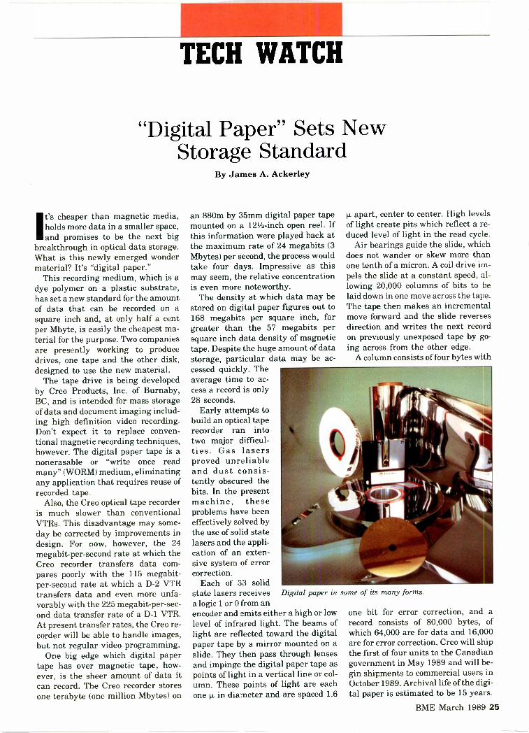
A column consists of four bytes with
Digital paper in some of its many forms.
one bit for error correction, and arecord consists of 80,000 bytes, ofwhich 64,000 are for data and 16,000are for error correction. Creo will shipthe first of four units to the Canadiangovernment in May 1989 and will be-gin shipments to commercial users inOctober 1989. Archival life of the digi-tal paper is estimated to be 15 years.
BME March 1989 25

Audio -for -video has neversounded this good.
IJ 1 4
Now you can have Grass Valley Groupcontrol in an Audio Mixer. With the AMX-170S.
If you've been working withGrass Valley Group productionswitchers and editors, you knowwhat we mean by GVG®qualityand reliability. And, you knowthat features like E-MEM® EffectsMemory and Effects Recall giveyou the best editor-to-switcher-to-peripheral communication in thebusiness.
Now, when it's time to do youraudio mix, you can have that sameGVG control. With the GVGAMX-170S Audio Mixer.
The AMX-170S is a powerful,automated audio mixer withfeatures typical of higher pricedmixing consoles. And, it providesunparalleled performance in thevideo production environmentby integrating fully with yourcomputerized editor.
So find out more about howyou can get GVG control in theeconomical and powerful AMX-170S Audio Mixer. Contact yournearest Grass Valley Grouprepresentative today.
Circle 113 on Reader Service Card Page 63
Grass Valley Group
A TEKTRONIX COMPANY
AA_THE GRASS VALLEY GROUP INC.
P.O. Box 1114, Grass Valley, CA 95945 USATelephone (916) 478-3000TRT: 160432
OFFICES: New York (201) 845-7988; District of Columbia(301) 622-6313; Atlanta (404) 493-1255; Chicago (219) 264-0931;Minneapolis (612) 483-2594; Dallas/Fort Worth (817) 483-7447;Los Angeles (818) 999-2303; San Francisco (415) 968-6680;GVG International Ltd. (U.K.) + 44-962-843939;Grass Valley Group Asia (HK) + 852-3-7396632

Two obvious areas of applicationsuggest themselves. One is the inex-pensive storage of great volumes ofdata such as is produced by medicalimaging, geophysical surveys andmeteorological, mapping and defenseimaging from satellites. The other isthe inexpensive archiving of exten-sive data such as tax and businessrecords. As Creo's marketing man-ager, Lou Misshula points out,"Availability will create new applica-tions. When the product comes on themarket, potential users will see appli-cations they don't now contemplate."
Bernoulli Optical Systems Corp. ofBoulder, CO, a subsidiary of Iomega,is developing an optical data diskdrive (ODDD) that will use digital pa-per in the form of a flexible 51/4 -inchdisk. This drive, which companyspokesman Andy Goldstein expectswill be ready for market in about ayear, takes advantage of Bernoulli'seffect, a principle of physics, to allowthe disk to come very close to the opti-cal head without danger of crashing.
Because of Bernoulli's effect, airflowing between the disk and a platelocated above the disk draws the disktoward the plate on which themicrohead is mounted and, at thesame time, provides a cushion of air tomaintain a constant distance (on theorder of 1 p.) between the disk and thehead. Any failure or interruption ofthe flow of air that maintains theseparation between disk and headalso causes the disk to fly away fromthe head-a built-in safety feature.
According to the company, the sys-tem replaces the usual focusing servowith a lightweight fixed focus and re-places the secondary fine positioningmechanisms with servo -system track-ing. Capacity of the digital paperdisks is 500 Mbytes per side.
The digital paper itself is made byImagedata, a subsidiary of the chemi-cal company ICI. This material, a 25 p.thick Melinex polyester -based sub-strate covered with a layer of dyepolymer, records the digital informa-tion transmitted by narrow beams ofinfrared laser light. According to Da-vid Owen, developments executive for
TECH WATCH
storage products at Imagedata,"Chemically bonded dye absorbs en-ergy in a narrow bandwidth, specifi-cally the 830nm infrared wavelengthof the laser. This energy, at the pointwhere a high -intensity laser beamhits the digital paper, expands the dyeand sets up a stress gradient with thesurrounding material. The resultingplastic flow forms a physical pit or de-pression 1 p. in diameter. The thin dyein the area of the pit does not reflectlight as well as it does elsewhere. Forthis reason, the recorded informationcan be read by sensing the reflectionof a laser directed to the same area."
Digital paper clearly has a brightfuture in the areas of imaging anddocumentation. Data from any activ-ity that can benefit from the mainte-nance of vast data files, such as satel-lite and other imaging, need neveragain be inaccessible or nonexistentdue to considerations of space or ex-pense. While the average broadcastengineer is more likely to be affectedby records kept on digital paper thanhe is to find himself loading it into aVTR, direct studio applications arecertainly possible in the future.
Ackerley is BME's technical editor.
9 l
Laser Diode
CollimatorLaserBeam
CREO TERABYTEOPTICAL
TAPE DRIVE
Air Bearing
OpticalEncoder
INPUT kDATA r
LASERDIODE
DRIVER
Recording data on a digital paper tape.
COILDRIVE
BME March 1989 27
vva44 d° lc.°
,ony's new digital recorder
Orkvleith
Your'111.9/09
equipment?
You can slip Sony's newcomposite digital video re-corder right into your currentediting suite. With its analoginputs and outputs, it con-nects directly to your existingequipment.
Yet it does what only digi-tal can do. For example, theSony DVR-10 composite DTTRgives you more than 20 gener-ations of transparent digitaldubbing. And with its write -
after -read capability, one
machine can operate simulta-neously as both a source andrecorder.
The DVR-10 is physicallysmall-half the size of a BVH-2000 recorder-and its priceis as compact as its size.
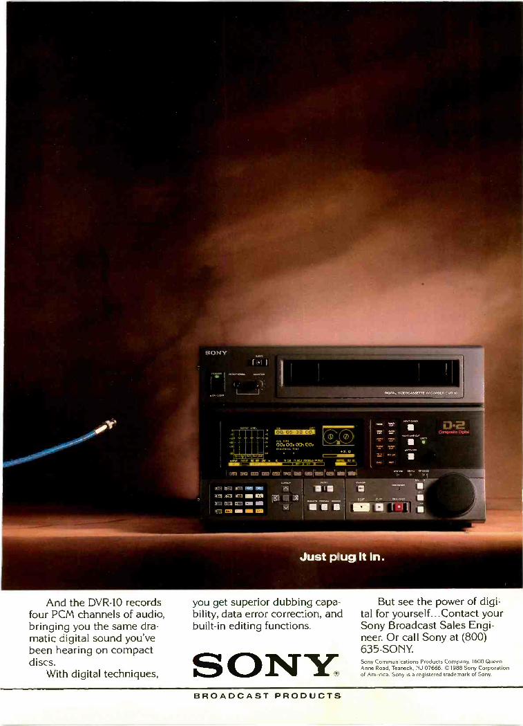
Just plug it in.
And the DVR-10 recordsfour PCM channels of audio,bringing you the same dra-matic digital sound you'vebeen hearing on compactdiscs.
With digital techniques,
you get superior dubbing capa-bility, data error correction, andbuilt-in editing functions.
SONY,BROADCAST PRODUCTS
But see the power of digi-tal for yourself...Contact yourSony Broadcast Sales Engi-neer. Or call Sony at (800)635 -SONY.Sony Communications Products Company, 1600 QueenAnne Road, Teaneck, NJ 07666. ©1988 Sony Corporationof America. Sony is a registered trademark of Sony.

PUBLICPERFECTION
A .4 .4,. *Owrzi L_ L_
Despite its reputation for high -qualityproduction, WGBH hadn't upgraded its routing
facilities since the early 1960s. A new rebuild haspropel red the station into the 1990s and beyond.
his was the lowest steer-age compartment of theTitanic. I had seen plentyof facilities coast to coast,and this was the worst."The speaker was Jo?. An-
derion, manager for production ser-vices at WGBH-TV Channel 2 andWGBX-TV Channel 44 in Boston andthe occasion was a ribbon -cutting cer-emony held last December 16 in thestation's newly rebuilt master controlroom. If the place had once been a di-
saster, there was no evidence of thatnow. Everywhere consoles, panels,equipment racks, walls, ceilings andfloors looked more like the main deckof a newly launched QE -2 than thebilge of some rotting hulk. It was ac-tually the scene of a great transfor-mation both in appearance and incapability for the present and for thefuture.
BY JAMES A. ACKERLEY
The heart of this new facility whichhas risen phoenix -like from the rav-ages of age and neglect is a remark-able routing switcher designed byBTS with the cooperation of WGBHengineers and featuring a flat re-sponse of 0.5 dB over a bandwidth of30 MHz. The new facility includes, inaddition to the new master controlroom, two completely reconstructedand modernized studios and three editsuites.
The WGBH Educational Founda-30 BME March 1989

ion in Boston is one of two main PBSroduction centers-the other is atNET in New York-and as such is
the source of about one-third of allPBS national programming. PBS pro-ductions have earned a well -deservedreputation for quality, but this has of-ten reflected the dedication of the en-gineers rather than the environmentin which they work.
Anderson recalls his first visit toWGBH some 14 years ago, "This wasthe worst place I had ever come to, itwas a hellhole. I was working on aPBS series that required captioning.There were two one -hour programsneeding 400 to 500 captions each andit couldn't be done in Hollywood with-ut doing it piecemeal and going down
a generation. This was the only placein the country that could do it. Every-thing in the WGBH engineering arealooked like it had been set up for somekind of emergency, but the attitude ofthe engineers was great." Later, asthe newly appointed head of produc-tion services at WGBH, Anderson setabout improving the working envi-ronment of the place.
The planning phase for a completerenovation began in March of 1985with the first money for design allo-cated in September of the same year.Except for layout drawings to satisfythe building code and the require-ments for the necessary permits, allelectrical and construction design wasdone in-house. Personnel resourceswere considerable. The WGBH Edu-cational Foundation employs about700 people of whom 115, including 60engineers, work in production ser-vices-the largest single departmentand the technical center for WGBH.
The problem was not the number ofengineers and others available for theproject, but the fact that everyone in-volved in the renovation effort had tocontinue his regular duties and thatall broadcast and other facilities hadto remain functional amid the din andconfusion of reconstruction. It is agreat tribute to the overall control ofthe director of engineering, DavidMacCarn, and to the day-to-day direc-tion of the engineering head of designand transmission, Dave St. Onge,that the work progressed smoothlyand that a total of only 20 seconds ofair time were lost during the entire
`As soon as highdefinition television(HDTV) technologyprogresses to the
marketplace, WGBHwill be in a position to
broadcast highdefinition and digitaltelevision."-St. Onge,
WGBH-TV
project.According to MacCarn, "[The
project] started when I got here inMarch of 1985. [It's a] plan that's go-ing to extend and extend and extend.We took all of the routing and mastercontrol in the plant [which] went backto 1963 and completely redid it. Theold system had been added onto manytimes and an update was overdue."
Planning began when it did be-cause money and people were thenavailable. The old technology re-quired heavy maintenance, also thesecond TV channel (WGBX-TVA hadno dedicated master control switcher.Planners expanded both TV channels,making many more sources availablethan with the old equipment. One im-mediate benefit of this expansion isthat WGBX-TV is now one of the fewUHF stations in the country to broad-cast stereo.
In regard to the design of the rout-ing switcher which made everythingelse possible, the station took itsspecifications to several vendors.They finally selected Bosch (BTS) asbeing best able to meet their require-ments and ended up making manytrips to Salt Lake City in order towork closely with them on the designand testing of components. As a resultof this close collaboration, the stationrequirements have become the BTSspecifications for high -end routing.
The newly developed switcher is100 x 100 in a 200 x 200 frame with100,000 cross points. It has beenadded to the BTS product line asmodel 2001. BTS and WGBH enteredinto agreement to design the switcherin the fall of 1986. The video portion
was delivered in March 1988 with theaudio portion having been deliveredearlier Frequency response is 0.5 dB,or virtually flat, over a bandwidth of30 MHz and only 3 dB over a band-width of 60 MHz. In effect, the onlything that limits the bandwidth is thecable itself.
Because all departments of WGBHmust stay competitive with the mar-ket at large, the engineering depart-ment took the opportunity of the re-build to accommodate future techno-logical requirements. A full 30 MHzbandwidth HDTV distribution systemon three channels is in now in place;when this is coupled with the BTSswitcher, the station is now able toproduce high -definition video signalsand distribute them anywhere aroundthe WGBH plant. Material which isproduced in high definition for otherclients must currently be bicycled tothem. St. Onge observes that, "Assoon as high definition television(HDTV) technology progresses to :hemarketplace, WGBH will be in a posi-tion to broadcast high definition anddigital television. We are the only sta-tion nationwide that has a routingsystem that can handle an HDTV pro-duction signal. The technology is ap-proaching at a rapid speed and we'reready."
Actual work began in the fall of1986. Everything was done in-houseusing WGBH personnel except thecarpentry work on the floors andwalls which was contracted out. Thenew master control has 40 times morecapacity for video signal distributionand over 80 times more audio capacitythan the station's old system. Thereare 132,800 different combinationsfor connections of equipment through-out the station including redundantemergency connections. Concealedbeneath the floors is over 23 miles ofnew video cable plus over 11 miles ofaudio cable.
The master control area consists inpart of the routing switcher and twoidentical master control rooms, onefor channel 2 and the other for chan-nel 44. Everything in the master con-trol rooms is brand new. In addition toitems such as the microwave switcherwhich was designed and built in-house, each room contains a BTSmodel 2000 master control switcher,
BME March 1989 31

two Tektronix model 1750 videowaveform monitors, three Ikegami14 -inch color monitors, 12 Panasonicthree-inch color monitors, sixIkegami nine -inch black -and -whitemonitors and the equipment arsenalis filled out with two Sony model BVU800 3/4 -inch VTRs.
Other new equipment for the mas-ter control area includes a Sony model3000 CCD camera for use as a filmchain and two Betacart videocassetteplayback systems. The intention is toconvert to full Betacam (SP) as far aslocal promotions and productions areconcerned.
Not only has the WGBH Educa-tional Foundation caught up with therest of the industry, the entire facilityis now in a position to move ahead ofthe industry in the rapidly developingareas of HDTV and digital processing.According to MacCarn, "We are look-ing at various projects and will proba-bly buy some HDTV equipmentwithin the next few months to a year.We will also look at composite digitalfor the next upgrade of our post -pro-duction environment."
As a nonprofit organization, WGBHis strictly accountable for the funds itexpends. It chooses, in turn, to makeeach of its departments show a returnon investment independent of theorganization as a whole. The effect isthat each department operates asthough it were an independent com-
The cost of renovatingstudio B was justified
by the increase inrevenues resulting fromthe simple expedient ofmaking the studio Bcontrol room into acombination controlroom and edit suite.
pany. Everything is on a strict cashbasis and each department rates allusers of its services even if the userhappens to be WGBH or a division ofWGBH.
Revenue for new equipment or ren-ovation must be generated by the de-partment requesting the expenditure.The new master control system hadbeen badly needed for a long time, butit could never have come into exls-tence if department revenues had notbeen sufficient to cover the expense.In the final analysis, it was Ander-son's ability to manage money thatmade it possible.
Of the various edit suites and stu-dios, all of which were in a sad state ofaging and neglect, the studio B con-trol room was the very worst. The lay-out was poor, there was little space inwhich to move around or do work, a
Opening page: Engineer Ken Corcoran in the channel 44 master control room with hishand on the microwave switcher. Like much of the new equipment, the switcher is an in-house product. Above: BTS model 2000 master control switcher located in the channel 2master control room.
number of exposed cables gave the ap-pearance of clutter and imperma-nence with much of the equipmentdating back to the early 1960s. StudioB was clearly the area of greatestneed and, as it happened, was also thearea where the greatest improvementwas possible and the greatest expen-ditures could be justified. As a result,the studio B control room has become,outside of the new master controlroom, the site of the WGBH facili-ties most dramatic broadcast chainimprovement.
The entire WGBH EducationalFoundation occupies some sevenbuildings, but because of the space re-quirements of the other departments,there was no way for support servicesto expand its space allotment. Therewas, however, a way to enlarge thefloor area of the studio B control room.This was done by sealing off a stair-way that was no longer needed. Therewas also a way to give both studio Aand studio B access to a larger num-ber of cameras. Camera control equip-ment previously shared by the twocontrol rooms was brought from themaster control room up to the secondfloor and divided between studio Aand studio B. This made it possible toshare cameras between the twostudios.
The cost of renovating studio B, theexpense of purchasing new equipmentto replace existing equipment and thepurchase of equipment not previouslyowned was all justified by the in-crease in revenues resulting from thesimple expedient of making the studioB control room into a combinationcontrol room and edit suite. The in-crease in revenues simply resultedfrom post -production work beingmore profitable than production workand, consequently, the payback on in-vestments in post -production equip-ment being greater than the paybackon similar investments in productionequipment.
Since much of the equipment isused for both functions and since thefacility is rarely used as a controlroom except at night, adding theediting function was an excellent wayto bring in the money to pay for boththe renovation and the new equip-ment. At night, as a control room, thefacility serves the nightly news and
32 BME March 1989

arriw I
You told us what youwanted, and how muchyou wanted to pay...
We did it!We called every radio station in America. Most li<ely
we tall-ed to you. We asked what you wanted in al on -the air boars and how much you wanted to pay.
We desigred and built it. We named it AP -100. t hasall you. features plus many more.
You Said you would pay between five and ten thju-sand cbllars We did it.
Check it out-we think you'll find it's just what youwantec. Circle 114 on Reader Service Card Page 63
Harriam Sy/ems Inc. P.O. Box 290157 Nashville, TN 37229
:615) 834-1184 FAX (6151834.1365

other local productions. In the day-time, as an edit suite, it serves theneeds of post -production.
In addition to the actual increase inspace for studio B, the greatly im-proved layouts, redesigned consolesand new under -the -floor cabling pro-vide all areas with a great deal morefunctional space than existed underthe old system. The feeling, totallyunknown before the renovation, is notmerely one of adequate space but ofroominess and freedom.
New equipment replacing existingequipment in the studio B controlroom/edit suite includes the GrassValley model 300 digital productionswitcher, the Grass Valley editor,model 51, the Rupert Neve model5114,24 x 4 x 2 stereo console, and theHarris VWS stillstore. New first timeequipment includes the Chyron model4100 EXB character generator andthe NEC System 10 digital video ef-fects (DVE) system.
Edit suite no. 1 also has a newChyron model 4100 EXB charactergenerator and a new NEC System 10DVE in addition to an existing Nevemodel 5114 audio production 24 x 4 x2 mixing console, a Grass Valleymodel 51 editing system with 256 kBof memory and a Grass Valley model300-2A 24 -input video productionswitcher.
Edit suite no. 2 shares a Chyronwith edit suite no. 3 and has, in addi-
The new mastercontrol system had been
badly needed for along time, but it could
never havecome into existence ifdepartment revenues
had not beensufficient to cover
the expense.
tion, a new NEC System 10 DVE, anexisting Central Dynamics model 916 -input video production switcher, aGrass Valley model 51EM editingsystem with 2 MB of memory and aTweed model 12/4 audio mixingconsole.
In addition to a new NEC System10 DVE, edit suite no. 3 has a GrassValley model 100 video productionswitcher, a CMX model 340XP editsystem with 28 kB of memory and aNeve model Kelso 10 x 2 audio mixingconsole.
Studio A shares six cameras withstudio B: five Ikegami model HK312and one Ikegami model 79D. Addi-tional studio A equipment includes aQuantel DPE 5000 DVE, a Central
These BTS power supplies provide the power to activate the BTS routing switcher.
34 BME March 1989
Dynamics model CDL 480 productionswitcher and a Neve model 5315 24 x4 x 2 audio console.
Other equipment distributedamong the three edit suites includesseven model 528, two model 1750 andtwo model 1480 Tektronix videowaveform monitors, five model 1420Tektronix video vectorscope monitorsand one model 1740 Tektronix videowaveform/vectorscope monitor. Alsoin this category are 15 Sony VCRs in-cluding five model BVH-2000 Type CVCRs, one model BVH-2500 Type CVCR, three model BVH-1100A VCRs,one model BVH-1000A VCR, fourmodel BVU-800 Umatic VCRs, onemodel BVU-200 Umatic VCR andfour Beta machines.
The transformation of WGBH fromone of the most backward to one of themost modern facilities in the nation isyet another example of what to expectwhen engineering excellence is sup-ported by progressive management.
The WGBH rebuild is remarkablefor several reasons. For one thing, it'sa public station. While known forquality programming, public stationsoften don't have the budget to produceit. Although WGBH has maintained areputation for very high -quality pro-duction, its facilities have been inpoor physical condition for a longtime. This upgrade has made its tech-nical facility one of the best in thecountry.
The WGBH rebuild is remarkablebecause in all the confusion and noiseof rebuilding, normal station opera-tions continued and, over a two-yearperiod, the station lost a total of only20 seconds of air time and even thatwas lost in several small bits ratherthan all at once. This is better thansome stations are able to do withoutdistractions and illustrates the care-ful planning that went into theproject.
The WGBH rebuild is remarkablebecause it solved the problem of inad-equate space not by adding space, butby cleverly reallocating the space ithad. And finally, the WGBH rebuildis remarkable because it was not sub-sidized by the government, or by agrant, or even by another division ordepartment within the same orga-nization, but was paid for by the prof-its from the investment.
Ci-cle No. 115 on Reader Service Card Page 63

7r/
. .
WRITTEN WORD. ALL ITS POWER UNDONE BY SLOW, TYPE-ONLY-ON-A-STRAIGHT-UNE,
..;

RID INSI

0rn3 0'690
4.k. 42 <4
> co
01)
...,c.,41
A44cr
EXPLODE

ALEX.- Truly a lexical character geneVirtually unlimited character manipulation and
real-time animation...true perspective... full antialiasingin every mode... and easy to use, with a model for every budget...
but don't read about it...SEE IT! Call or write for afree VHSdemo tape showing the full range of dynamic effects.
You'll never be satisfied with just a character generator again!Call your nearest Ampex sales office today.
GET YOUR HANDS ON ALEX AT NAB!
AM PEXAtlanta (404) 491-7112 Boston (617) 932-6201 Chicago (312) 593-6000 Dallas (214) 960-1162 Los Angeles (818) 365-8627
New Jersey (201) 825-9600 (In New York (212) 947-8633) San Francisco (415) 367-2202 Washington D.C. (301) 530-8800 Canada (416) 821-8840
C Ampex Corporation 1989

CAVEAT: WHITEPAPER II
RECOMMENDATIONS ON AUDIO FOR
THE VISUAL MEDIBIAt the onset of this decade, things were simpler. When aburgeoning audio technique caused confusion among videoproducers in Chicago, 10 people got together and discussedthe problems over a two -month period. The result was afour -page White Paper on audio for video. But thingswould never be that simple again.
Back in 1982, "audio sweetening" was already a part ofmost producers' vocabularies. The practice was technologi-cally mature, but procedures and equipment varied fromplace to place. And since terminology was nonstandardand too often misleading, producers sometimes had diffi-culty coordinating a project when multiple post facilitieswere involved. In reponse to these concerns, the ChicagoCoalition, an organization of producers and services char-tered to strengthen the local production environment, in-vited interested parties to get together to write a paperthat would recommend exchange practices between videoand audio facilities. After five evening meetings, represen-tatives of the Coalition, along with four audio and threevideo companies, had compiled a four -page documentspecifying preferred exchange formats, speeds and headertones and stressing the need to communicate with otherservices when problems occur.
The motives of the Chicago Coalition were not totallyaltruistic: if these rules of order could streamline work andreduce stress in Chicago, work would remain here. Freefrom disputes among facilities, producers could confi-dently use different facilities for differing operations.
Over time, the proliferation of audio and video formats,not to mention stereo television, begat situations the origi-nal White Paper had not addressed. In late 1986, an inde-pendent committee of engineers, which would eventuallybe called C.A.V.E.A.T., proposed an update. The commit-tee started with well -attended "town hall" meetings, thenprogressed to subcommittee field study and actual writing.The working paper was excerpted in the 1987 handbook ofthe International Teleproduction Society.
White Paper II on Audio for Video dramatically eclipses
The C.A.V.E.A.T. committee. Seated (L to R1: Rebecca Albrecht,recording secretary, Optimus, Inc.; Ric Coken, executive chairman,Zenith/db Studios. Standing (L to RI: George Slominski, video co-chairman, Optimus, Inc.; Patrick Garvey, recording secretary,Genesis Creative Group; Donald T. Adydan, video chairman,Optimus, Inc.; Tom Miller, midi.° chairman, Universal RecordingCo. Not pictured: Mike Moats, audio co-chairman, Zenith/dbStudios.
its predecessor in size and scope, much as the new technol-ogy has the old. Broadcasters, editors, mixers, technicalmanagers and engineers, as well as facility owners, con-tributed their talents for the two-year effort.
In White Paper II, C.A.V.E.A.T. has produced an excep-tional document under exceptional circumstances: com-petitive services in a single locality, freely giving of in-formation and time. C.A.V.E.A.T. will continue tochampion what has been honored since the first WhitePaper-open communication, quality in our work andpride in our industry.
Circle 115 on Reader Service Card Page 63BME March 1989 39

C.A.V.E.A.T.
CONTENTS
Section I: LABELING & STORAGE 40 Section VII: TIME CODE 53Part A: General Labeling 42Part B: Technical Labeling 42 Section VIII: NOISE REDUCTION 53Part C: Format Specifics 42Part D: Storage 42 Section IX: TIME COMPRESSION 56
Section II: HEADER GEOGRAPHY 45 Section X: STEREO & MTS 56Part A: Recording the Header 46 Part A: Format of Channels 56Part B: Playing the Header 46 Part B: Phasing 56Part C: Explanation 46 Part C: Monitoring 61Part D: Rationale 47
Section XI: TEST TAPES 61Section III: FORMATS & TRACK ASSIGNMENTS 47Part A: Exchange 47 Section XII: MONITORING & ACOUSTICS 61Part B: Dubbing 47 Part A: Signal to Noise 62Part C: Format Comparison 48 Part B: Frequency Response 62
Part C: Loudspeaker Selection 62Section IV: OPERATIONAL LEVELS 48 Part D: Acoustic Treatment 62
Part E: Electrical Treatment 63Section V: FIELD RECORDING 48 Part F: Stereo Imaging 63Part A: Format 48 Part G: Monitoring Practices 63Part B: Tones 48Part C: Level 53 Section XIII: GLOSSARY OF TERMS 63Part D: Slates 53
Section VI: BETACAM & MII 53
INTRODUCTIONThe information that is contained in this document is rep-resentative of more than a year's effort on the part of agroup of audio and video production and post -productionprofessionals. This "white paper" is evidence of a continu-ing emphasis by professionals to provide clients with thebest possible product available.
The technological and operational advances that haveoccurred in the production community, by both equipmentmanufacturers and users, have been extreme and continu-ous. With that in mind, the following is a sincere attempton the part of the authors to establish a set of recom-mended standards and procedures in the use and exchangeof audio materials for use with picture. The key word hereis recommended.
From the outset it was acknowledged that guidelinescould not be formulated that would require significant op-erational restructuring of any given facility. Instead, thefocus of the group was to limit its recommendations to a)current technology that is in place and is used as part ofthe daily operations of a facility, and, b) professionalaudio for film or video that would be used as an exchangemedium between facilities or as a finished releaseproduct.
For these reasons, as you read through the Recommen-dations on Audio for the Visual Medium, you will noticethat there are only mentions of such emerging technol-
ogies as S -VHS, D1, D2, etc. These new technologies repre-sent the newest innovations in audio and video but are notyet widespread enough in the marketplace to be consid-ered commonplace "exchange" technologies. The authorsare aware that, with rare exception, the current use of thelatest hardware is probably limited to the internal opera-tions of a facility.
The combined list of committeemen, forum attendeesand supporters in kind is too lengthy to appear here, butdoes appear in the appendices. The committeemen wouldalso like to extend a general word of thanks to all who gavetheir input and support to this effort and to you, the user,for taking the time to refer to these writings. Comments,criticisms and suggestions are encouraged and welcomed.Please send your correspondence to: CAVEAT c/o 770 N.LaSalle Street, Chicago, IL 60610.
Section I: LABELING & STORAGEAmong the items of highest concern with the committee isthe ability to recover information pertaining to the condi-tions under which a recording was made. Concise labelingand proper storage techniques are essential steps in themaintenance and exchange of quality recorded material.
In an effort to standardize label content, it is recom-mended that several items regularly be included on labelsfor both audio and visual materials. This information, ex-emplified in Figures 1 and 2, can be categorized into two
40 BME March 1989

C.A.V.E.A.T.
major areas: general and technical.
Part A: GENERAL LABELING
Company name, address and phone number (includingarea code). Client name. Product code and description. Additional space can beprovided by affixing a label or attaching a reference sheetto the interior of the reel box. Client reference number. Date of the recording. Editor, recording engineer, or company contact. Reel number and the total number of reels in the job orsession. Tape recorder and/or studio used for the recording. Tape operator, if applicable.
Part B: TECHNICAL LABELING
Qualification of the recording. The generation of record-ing should be clearly indicated. When the term "Master" isused, it should be qualified with a modifier as indicated inthe Glossary of Terms. Format and/or tape size. Tape stock manufacturer and tape type. Type of audio recording and/or number of channels. Mon-aural, stereo, N -Channel element (N = number of chan-nels) and N -Channel master are examples of types of re-cording; as indicated in the Glossary of Terms. Placement of audio signals on tracks. Reference or time code signals recorded and their place-ment, when applicable. Type of noise reduction used, if applicable. The appropri-ate reference tones should be recorded in the header whennoise reduction is used. Use of time compression, if applicable. The correspond-ing original duration and re-recorded duration should beindicated on the label. Reference level (nWb/m) used for 0 VU. Especially appli-cable to audio formats. Type and placement of reference tone sequences. A refer-ence tone sequence, such as the CAVEAT standardheader, is used for determining operational level and fre-quency response characteristics of program material.
To further clarify characteristics that are unique to indi-vidual audio and video formats, the following informationis recommended to be in the respective labeling categories.
Part C: FORMAT SPECIFICS
Audio Format Speed of the recording. Equalization of the recording. Type of digital recording, if applicable. Type of automation used in the mixing process, ifapplicable.
Video Format Presence of closed captioning material and placement ofthe encoding in the vertical interval. Indication if the product has Visual Time Code, some-times called Window Time Code or Burn -In Time Code.
Figure 1
COMPANY NAMECOMPANY ADDRESS ALSO AREA CODE AND PRONE NUMBER
CLIENT
PRODUCT.
REEL OF
CLIENTS I 0FILE /
DATE
ENGINEER
ASSISTANT
STUDIO
MONO STEREOMASTER COPY
LEVEL nI16/1.1 .4 0 1.41
TONES READ TAA.TONE 470410.10'
CAVEAT STANDARD OTHER STANDARD SPECIFY
0IANNEL DESCRIPTION
CH2- 013- 044-CHI-
Face label
SIZE 0 1/4' 0 1/2" 1' 0 rTRACK FORMAT FULL 2 4 8 18
24 32 2880/4 *SPEED 0 7.5 0 15 0 30
EC/ NAB AES IECPULSE NECPLT FM 60 HA CHSAM 3031 3014 DROP 2431
COM 7K. 04TAPE TYPE
NOISE REDUCTION TYPE
OME COMPRESSION
(DURATION ORG./DURATTON NEW)
DIGITAL TYPE AUTOMATION TYPE
SEE INSIDE
TAKE 0 TIME TITLE COMMENT
Figure 2a Face label
COMPANY NAMECOMPANY ADDRESS ALSO AREA CODE AND PHONE NUMBER
(OPTIONAL TITLE SPACE)
DATE: JOB NUMBER.TECHNICAL SPECIFICATIONS
EDITED MASTER REEL OF
SAFETY CH.1
DUB CH.2DUBBING MASTER
SUBMASTER
ORIG. FILM TRANSFER ORIG. FIELD RECORDING
SUE CODE OF/NDFLTC
CH.
VITC
UNESVISUAL T.C.
CLOSED CAPTIONUNES
RECORDING VTRREC. VTR OPT. FOR:
TAPE MEMTAPE FORMAT
BUNKING H-V-OPER NIT
AUDIO
0DUAL INDEPENDENT (MIX FOR DUBBING)
2-CH. MONO STEREO
LEFT ON CH.RIGHT ON CHNOISE REDUCTION
TYPE:TIME COMPRESSION
(DURATION ORG./DURATION NEW)TONE SECCIFNCKCAVEAT STANDARD OTHER STANDARD
SPECIFY
LEVEL nIMD/M
Figure 2b Edge label
Ev
(TITLE SPACE)
g 5U
Horizontal (ii.sec.) and vertical (lines) blanking measure-ments recorded at 4 IRE to meet RS -170 standards or 20IRE to meet RS -170A standards.
Part D: STORAGE Audiotapes should be stored "tails out" to help prevent
BME March 1989 41

C.A.V.E.A.T.
Figure 3
VIDEO
AUDIOCH -1
(LEFT)
AUDIOCH -2
(RIGHT)
TIME CODE
SEE NOTE 9
SEE NOTE I
MANDATORY -r BEEP, 1 FRAME LONG
SEE NOTE
SEE NOTE 2
SEE NOTE 3 -
BLACK 10 sec. SMPTE NTSC COLOR BARS 50 sec. 1 SLATE5 sec. E
aN0TE4
PROGRAM VIDEO MINIMUM OF10 sec. BLACK
1 kHz0 dB
10 sec.
1 kHz-5 dB5 sec.
63 Hz-5 dB5 sec.
5 kHz-5 dB5 sec.
10 kHz-5 dB5 see.
12.5kHz-5 dB5 sec.
PINK NOISE-10 dB10 sec.
1 kHz0 dB
5 sec.
SILENCE.5 sec.
°P11°NALSLAM
PROGRAM AUDIO
''>MINIMUM OF
10 sec. SILENCE
1 sec.DELAY
IkHz0 dB
IkHz-5 dB
63 Hz-5 dB
5 kHz-5 dB
10 kHz-5 dB
12.5kHz-5 dB
PINK NOISE-10 dB
1 kHz0 dB
SILENCE'5 sec.
C911°NALSLATE
GG.
PROGRAM AUDIO MINIMUM OF10 sec. SILENCE9 sec. 5 sec. 5 sec. 5 sec. 5 sec. 5 sec 10 sec. 5 sec.
CONTINUOUS ASCENDING NON-DROP FRAME SMPTE LONGITUDINAL TIME CODE ON HIGHEST NUMB:RED TRACK
NOTE 1: THE FIRST 1 KHz TONE IS FOR LEVELSETTING. THE NEXT 5 TONES AND PINKNOISE ARE FOR CHECKING FREQUENCYRESPONSE AND PHASE. THE LAST 1 KHzTONE AT 0 DB HAS THE POSITIVE PEAKCUPPED AT APPROXIMATELY 20% FORPOLARITY CHECK.
NOTE 2: TIME CODE AT FIRST FRAME OF PROGRAMVIDEO (FADE-UP) SHOULD BE ATXX: XX: 00: 00 (NON-DROP FRAME).
VIDEO HAS BLACK FOR 1 SECOND. 29 FRAMESAND AUDIO CHANNELS ARE SILENT FOR SAME.
NOTE 3: THE 10 SECONDS AT THE HEADS & TAILSIS WITH MACHINE THREADED.
NOTE 4. THE VIDEO COUNTDOWN SHOULD BE 3 SECONDSLONG, STARTING AT 5 AND ENDING WITHONE FRAME OF THE 2. AUDIO WITH THECOUNTDOWN CAN BE SILENT WITH A ONEFRAME BEEP AT THE 2, OR BEEP AT EACHSECOND UNTIL THE 2.
print -through, 70 percent of which occurs during the first24 -hours of storage. Videotape, especially cassettes, should be stored "headsout" to avoid hub impressions.
Subscribing to the use of these recommendations willcertainly aid in the best possible recovery of a recordedproduct. In any application however, the underlying ideashould be to provide the next professionals with the in-formation they need to do their jobs.
Section II: HEADER GEOGRAPHYThe CAVEAT Header serves several purposes. It is pri-marily a quality control test signal, but also serves toidentify program content and how it was recorded. Thisheader, as shown in Figure 3, contains synchronizing in-formation between picture and sound, and is designed tobe used with all audio materials intended for visual appli-cations. By using the header, operators will be able toreassure themselves and their clients of not only good au-dio, but that this audio is preserved from one generation tothe next.
Since the header test signal has been designed to havethe same duration as the currently used SMPTE color bartest signal, the additional operating cost is nominal. Theaudio header consists of eight (8) test signals, a place for aslate, and a synchronizing beep. Video tapes would alsoinclude color bars, visual slate, countdown, and a syn-chronizing mark. The header should be recorded on allaudio for use with picture.
In order to show the cumulative effect of each genera-tion, the header should be copied each time the program isduplicated. It is important that the header be kept with itsassociated program material. This practice is especiallyimportant with stereo programming, due to the sensitivityof its mono compatibility.
If the header is removed or damaged, the next user can-not guarantee that the quality of the material will bemaintained.
The main intent of the header is to flag the operator ifsomething has gone wrong in the post -production process.Operators are not expected to align equipment to match
each roll of tape that they receive. If, however, the headerindicates that a tape is questionable, the operator shouldcontact the source of the tape. The cooperative effort of thetwo companies should lead to the solution of the problemand help prevent its recurrence.
Table 1CAVEAT Header Geography
AUDIO LEVEL PLACEMENT DURATION FUNCTION(in VU) (Channel) (in seconds)
Noise optionalReduction 15 NR type ID
Tones
1.0 kHz 0 1 / 2' 10 Level set("NOTE: Right Ch. starts 1 sec. after left or Ch. identifierVoice Ch. ID for 1 sec.)
1.0 kHz -5 1 & 2 5 Equalization
Check
63.0 Hz
5.0 kHz
10.0 kHz
12.5 kHz
Pink Noise
-5
-5
-5
-5
-10
5
5
5
5
10
1.0 kHz 0 1 & 2 5
(**NOTE: Both Ch. positive sine wave topclipped approx. 20°0 from 0 axis)
Slate
Countdown
1 kHz 0
Silence
Program Material
Silence
Azimuth Check
Level,
Polarity Check
5 optional audio
3 (minimum) optional audio
1 & 2 1 FRAME SYNC
1 & 2 2 sec minus Pullup 1 FRAME
1 & 2 10 Runout
Part A: RECORDING THE HEADER
1) The header should be recorded on all audio materials forvisual use. Its use on check copies (client approval) isoptional.
42 BME March 1989

C.A.V.E.A.T.
2) The tones should be recorded simultaneously on all au-dio channels except the time code channel(s) and wherenoted.3) New tones (and/or color bars) should be created whennew program material is created, or when program mate-rial is altered (except time compression work).4) The header should be copied when material is copied(including time compression work).5) When segments are edited together, a header that isconsidered to be representative of the various parts shouldbe used.6) Multichannel film masters should include: header re-corded simultaneously on all tracks, then 5 -sec. segmentsof 1.0 kHz recorded sequentially on each channel.7) Digital recordings should have the full header since itwill be needed to check analog copies.8) If there is no time, or tone generating equipment islimited, at the very least, tones near 1.0 kHz and 10.0 kHzshould be recorded.9) For in -the -field recordings, when no oscillator is avail-able, the traditional tone at -8 on the quasi peak meter willat least provide a level reference. This tone can be treatedas 0 on a VU meter. Any additional tones would be veryhelpful to ensure that adequate transfers can be made.
Part B: PLAYING THE HEADER1) Set playback level using the first reference 1 kHz tone.2) Observe the tones that follow: frequency responseshould be better than +/-2 dB at all frequencies relative tothe -5 VU 1 kHz tone, and azimuth should be better than+/-30 degrees at 10 kHz. Tapes should meet these speci-fications when delivered to the final presenter. Thesespecs represent an error budget that has to be shared byeveryone that works with that program. Azimuth shouldbe maintained within +/-15 degrees per generation.3) If the tones are questionable, check the playback ma-chine with a test tape.
If the playback machine appears to be aligned properly,then contact the facility that supplied the recorded mate-rial. A decision can then be made as to whether a freshcopy can be made available. Notifying the source of theproblem tape also allows them to correct their equipmentto prevent further problems.
Part C: EXPLANATION
The committee decided that since the Header Geographyinformation supplied above may be quite different fromwhat your facility has been accustomed to using, an in-depth explanation of how the tone series was derivedwould be helpful.
Noise Reduction Identification Signal:Several types of noise reduction devices have an identify-ing signal. If noise reduction encoding is being used, thissignal will identify which type it is, and what the referencelevel is. Since not all units generate such a tone, its use isoptional. Therefore, it is important to refer to the labelinginformation to determine if noise reduction has been used.Since this tone is first in the header, it is easily omittedwhen a decoded copy is made; leaving this tone on a de-coded copy would cause much confusion.
Level Set Tone: 1 kHz at 0 VU:This tone represents average program level. This shouldmatch the test tape 0 VU level set tone. This is the onlytone in the header that needs to be used to adjust a ma-chine on a tape -by -tape basis. This signal will also give aclear indication of polarity match between channels.
Channel Identifier:The level set tone on the right channel starts 1 sec. afterthe left channel. The channels can be identified by listen-ing or by watching the meters. An alternate identifier is toreplace the first 1 sec. of the level set -tone with individualvoice announcements on the appropriate channels. Thetotal duration of the announcements should not exceed 1sec. Another alternative to voice announcements is onebeep on the left channel followed by two beeps on the rightchannel. The total duration of this set of beeps should notexceed 1 second.
Equalization Check: 1 kHz, 63 Hz, 5 kHz, 10 kHz, 12.5 kHzall at -5 VU:The first tone in the series is for the operator to pick areference point on his meters. The next four tones will becompared to this first tone. The EQ tones are at a reducedlevel to assure compatibility with all tape formats. Fre-quencies were chosen to display typical problems such ashead wear and alignment, electrical alignment, and choiceof equalization standard. The high frequency is also com-patible with the Altair wow and flutter analyzer.
Azimuth Check: Pink Noise at -10 VU:This provides a quick visual and audible check of headazimuth. Errors can be seen on an oscilloscope as a fuzzyball. If a mono sum is listened to, errors will be heard as ahigh frequency loss or swishing sounds. This signal mayalso be used for frequency response checks if a V3 octaveanalyzer is used. However, low frequency readings maynot settle on many analyzers within the 10 -sec. duration ofthis signal.
Level and Polarity Check: 1 kHz at 0 VU:This tone is intended mainly as a level reminder followingthe reduced level signals. In addition, the positive portionof the waveform is clipped approximately 20 percent. Thisserves to identify whether or not a signal is inverted. In-version errors are subtle if channels are matched in polar-ity. Recording formats are not standardized with respect toabsolute polarity. Therefore, inversion errors where bothchannels match can be left to the final exhibitor.
Slate:Visual and optional audio identification of program. Thisshould be a non -ambiguous description. If material is timecompressed or non -synchronous, it should be stated. A lowfrequency tone at a low level may be included to helpidentify this point on the tape when shuttling. The visualslate should be separate from the countdown. The slate canthen be revised without destroying the countdown.
Countdown:An accurate visual indication of time before program
BME March 1989 43
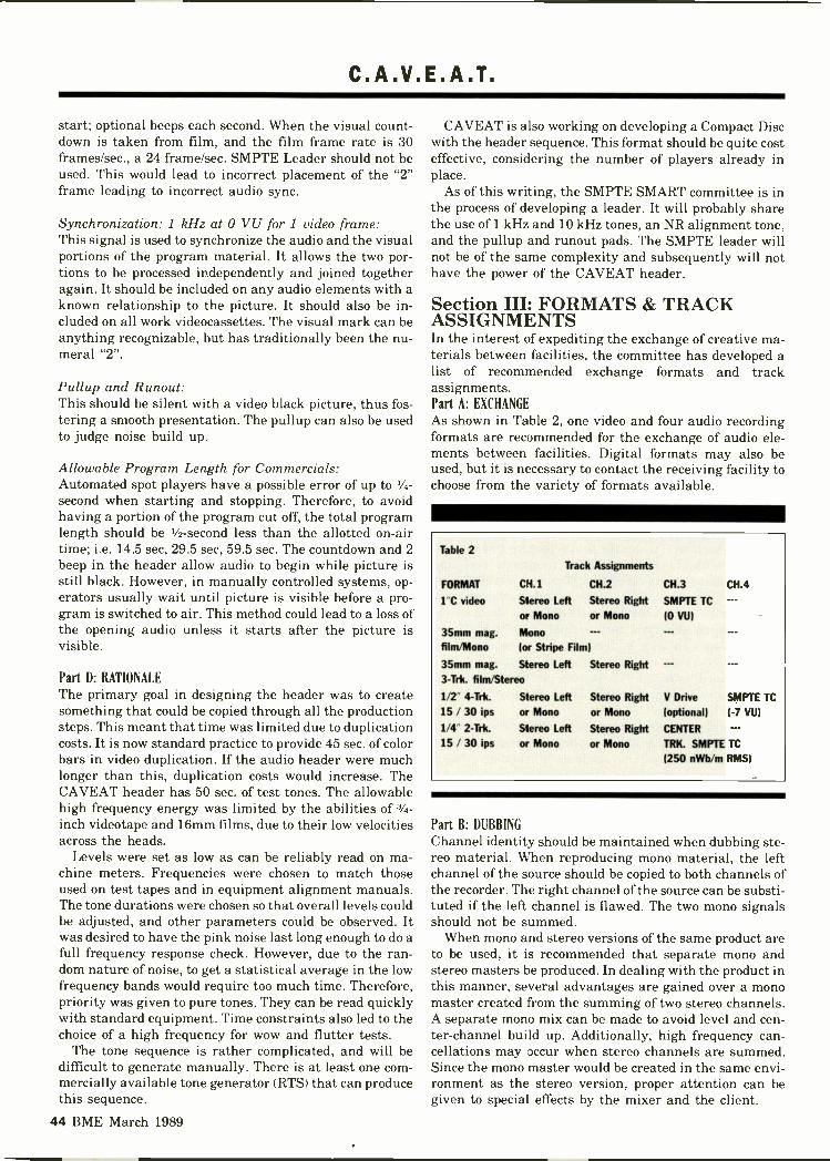
C.A.V.E.A.T.
start; optional beeps each second. When the visual count-down is taken from film, and the film frame rate is 30frames/sec., a 24 frame/sec. SMPTE Leader should not beused. This would lead to incorrect placement of the "2"frame leading to incorrect audio sync.
Synchronization: 1 kHz at 0 VU for 1 video frame:This signal is used to synchronize the audio and the visualportions of the program material. It allows the two por-tions to be processed independently and joined togetheragain. It should be included on any audio elements with aknown relationship to the picture. It should also be in-cluded on all work videocassettes. The visual mark can beanything recognizable, but has traditionally been the nu-meral "2".
Pullup and Runout:This should be silent with a video black picture, thus fos-tering a smooth presentation. The pullup can also be usedto judge noise build up.
Allowable Program Length for Commercials:Automated spot players have a possible error of up to 1/4 -second when starting and stopping. Therefore, to avoidhaving a portion of the program cut off, the total programlength should be 1/2 -second less than the allotted on -airtime; i.e. 14.5 sec, 29.5 sec, 59.5 sec. The countdown and 2beep in the header allow audio to begin while picture isstill black. However, in manually controlled systems, op-erators usually wait until picture is visible before a pro-gram is switched to air. This method could lead to a loss ofthe opening audio unless it starts after the picture isvisible.
Part D: RATIONALE
The primary goal in designing the header was to createsomething that could be copied through all the productionsteps. This meant that time was limited due to duplicationcosts. It is now standard practice to provide 45 sec. of colorbars in video duplication. If the audio header were muchlonger than this, duplication costs would increase. TheCAVEAT header has 50 sec. of test tones. The allowablehigh frequency energy was limited by the abilities of 3/4 -inch videotape and 16mm films, due to their low velocitiesacross the heads.
Levels were set as low as can be reliably read on ma-chine meters. Frequencies were chosen to match thoseused on test tapes and in equipment alignment manuals.The tone durations were chosen so that overall levels couldbe adjusted, and other parameters could be observed. Itwas desired to have the pink noise last long enough to do afull frequency response check. However, due to the ran-dom nature of noise, to get a statistical average in the lowfrequency bands would require too much time. Therefore,priority was given to pure tones. They can be read quicklywith standard equipment. Time constraints also led to thechoice of a high frequency for wow and flutter tests.
The tone sequence is rather complicated, and will bedifficult to generate manually. There is at least one com-mercially available tone generator (RTS) that can producethis sequence.
CAVEAT is also working on developing a Compact Discwith the header sequence. This format should be quite costeffective, considering the number of players already inplace.
As of this writing, the SMPTE SMART committee is inthe process of developing a leader. It will probably sharethe use of 1 kHz and 10 kHz tones, an NR alignment tone,and the pullup and runout pads. The SMPTE leader willnot be of the same complexity and subsequently will nothave the power of the CAVEAT header.
Section III: FORMATS & TRACKASSIGNMENTSIn the interest of expediting the exchange of creative ma-terials between facilities, the committee has developed alist of recommended exchange formats and trackassignments.Part A: EXCHANGE
As shown in Table 2, one video and four audio recordingformats are recommended for the exchange of audio ele-ments between facilities. Digital formats may also beused, but it is necessary to contact the receiving facility tochoose from the variety of formats available.
Table 2Track Assignments
FORMAT CH.1
1"C video Stereo Leftor Mono
35mm mag. Monofilm/Mono (or Stripe Film)
35mm mag. Stereo Left Stereo Right3-Trk. film/Stereo
1/2 4-Trk.
15 / 30 ips2-Trk.
15 / 30 ips
Stereo Leftor Mono
Stereo Left
or Mono
CH.2
Stereo Rightor Mono
Stereo Rightor Mono
Stereo Rightor Mono
CH.3
SMPTE TC
(0 VU)
V Drive
(optional)
CENTER
TRK. SMPTE TC
(250 nWb/m RMS)
CH.4
SMPTE TC
(-7 VU)
Part B: DUBBING
Channel identity should be maintained when dubbing ste-reo material. When reproducing mono material, the leftchannel of the source should be copied to both channels ofthe recorder. The right channel of the source can be substi-tuted if the left channel is flawed. The two mono signalsshould not be summed.
When mono and stereo versions of the same product areto be used, it is recommended that separate mono andstereo masters be produced. In dealing with the product inthis manner, several advantages are gained over a monomaster created from the summing of two stereo channels.A separate mono mix can be made to avoid level and cen-ter -channel build up. Additionally, high frequency can-cellations may occur when stereo channels are summed.Since the mono master would be created in the same envi-ronment as the stereo version, proper attention can begiven to special effects by the mixer and the client.
44 BME March 1989

Video That Sounds as Good as it Looks.
The video industry demands the same uncompro-mising audio quality the recording industry expects.Dolby SR signal processing and Dolby A -type noisereduction are now available on one processing boardfor the Sony BVH-3000/3100 VTR. Contact your Sony
Photographed at On Tape Productions, San Francisco, CA.
representative and inquire about the BKH-3080.Find out why recording and film studios aroundthe world rely onDolby for cleaner. DO Dolby SRquieter audio. spectral recording
Sony Communications Products Co. Phone 201-833-5200, Dolby Laboratories Inc., 100 Potrero Avenue, San Francisco,CA 94103-4813, Phone 4'5-58-0200, Telex 34409, Facsimile 415-863-1371 346 Clapham Road, London SW9 9AP
Phone 01-720-1111. Telex 919109, Facsimile 01-720-4118 Dolby and the Double -0 symbol, are trademarks of Dolby Laboratories Licensing Corporatian..4.: Dolby Laboratories Inc.1988. S88/8321/8339
Circle 116 on Reader Service Card Page 63

How Good is Our 3rd Generation?
, ,,eetTBC-200 Time Base Corrector
"pi...eV--;41-1104-4-ip-'
UTP-1 Signal Transcoder
NI' o 6-ix so to 11.:;.7,27:2
AG -7500A Editing VCR
CCD Cameras
IFP-44 Editing Inte ace
7 di
AG -7400 Portable VCR
.- \ .--..... le,......;..--. ..........-- lip.`"'" --- qiet......
\---
AG-A750 Editing Controller
SVHS Video Cassettes

Take a Look at Our 5th!
HorizontalResolution(Color Mode)
S/N Ratio (dB)
Luminance(Color Mode)
Chrominance(AM)
Chrominance(PM)
PERFORMANCE DATA(AG -7500A)
1stGeneration
57.2
51.8
44.3
3rdGeneration
w/o TBC w/TBC-200
51.7
47.5
40.1
360
52.0
51.4
43.8
5thGenerationw/TBC-200
Data represents measurements by independert engineering evaluation. VCRs taken at random frominventory.
Signal Source:Luminance:Chroma:Resolution:
Shibasoku TG -7/1 Noise Meter:50 IRE flat field w/burst Y-S/N:50 IRE w/100 IRE p -pMonoscope Shibasoku 58../1 C-S/N:
Cnom the first to the third, even toUthe 5th generation PanasonicSVHS Pro Series specificationsspeak for themselves. And theysay "outstanding:' Here are someof the reasons:
The AG -7500A editing VCRwith its new laminated amorphousheads produces superb qualitygeneration after generation.
The AG -A750 editingcontroller has everything youneed for highly accurate singleevent editing.
And the AG -7400 portable2 -hour VCR is a naturalperformer in the field.
Our TBC-200 time basecorrector has a 16 -line
Rohde & Schwarz LPSF2/UPSF2E2200 kHz HPF, subcarrier trapon1.2 MHz, LPF weighted" 00 Hz HPF500 kHz LPF unweighted
correction window, chroma plus/enhancement, chroma noisereduction and no -roll circuitry. Tomake multi -generation recordingseven better.
The UTP-1 signal transcoderis more than ready to transcodevirtually any component signalinto any other component signal.Saving you an extra generation.
The IFP-44 editing interfacecontrols Pro Series decks on boththe source and edit side. To easilyintegrate into selected 3/4"systems.
Our CCD Cameras areequally spectacular. And withthe Panasonic SVHS Pro Seriesyou not only get outstanding
350
49.0
44.5
35.2
performance, you also get theadded economy of 2 -houroperation in the field and inthe studio.
The Panasonic SVHS Pro Series.In a word it's outstanding.
For more information on thePanasonic Pro Series, callPanasonic Industrial Companyat 1-800-553-7222, or your localPanasonic Professional/IndustrialVideo dealer.
=VI -151
PanasonicProfessional/Industrial Video
Circle 117 rin Reader Service Card Page 63

C.A.V.E.A.T.
Part C: FORMAT COMPARISON
Many factors affect a recording channel's ability to repro-duce audio. Audio resolution may be influenced byattributes such as track width, linear tape speed, tapeoxides and equalization. Table 3 is representative of someof the recognized professional analog formats available.
Table 3
Recognized Professional Analog Formats
TAPE WIDTH
(inches) RECORDER TYPEAUDIO TRACK
WIDTH (inches)LINEAR
SPEED lips)
Audio Production1/4" FuII-Trk. Mono .234 30/15/1.51/4" 2-Trk. Stereo .080 30/15/*7.51/2" 2-Trk. Stereo .200 30/151/2" 4-Trk. .070 30/151" 8-Trk. .070 30/151" 16-T11c .035 30/152" 16-Trk. .070 30/152" 24-Trk. .037 30/15.125 *Stereo audio cars. .023 1.875*(Used for check copies only)
Film Production16mm Mono/edge trk. .200 7.2 @ 24 fps.(NOTE: at 30 fps. 16mm runs (a 9.0 ips.)
35mm Mono/stripe .200 18 @ 24 fps.35mm 3-Trk./full coat .200 18 @ 24 fps.35mm 4-Trk./full coat .150 18 @ 24 fps.35mm 6-Trk./full coat .100 18 @24 fps.(NOTE: at 30 fps. 35mm runs (a
Video Production
22.50 ips.)
2" Quad. .070 151" C format .0315 9.6061" B format .0315 9.6463/4"
U-matic .0315 3.751/2,, Betacam .023 4.671/2" MII .0236 2.67
Section IV: OPERATIONAL LEVELSThe purpose of setting operational levels is to ensure thatrecorded audio material can be exchanged without appre-ciable noise or distortion.Level Metering:a) Average Level should be near the 0 VU value estab-lished by the CAVEAT header tone reference level. b)Peak Level should not exceed 12.0 dB above 100 nWb/mreference 0 VU level. Recorded program levels should re-flect the level of the header tones recorded preceding theprogram. The average levels reflect perceived loudnessand will not fully show program peaks. Peak levels are ofparticular importance due to the direct relationship oflevel and distortion. It is recommended that the peak levelrecorded not exceed the 3 percent distortion point of thetape format for more than 10 milliseconds at a time. Forthe 1 -inch Type C format, a peak level of + 12 dB above100 nWb/m (0 VU reference level) will meet these criteria.
Metering of such parameters may be done in a variety ofways. The best recommendation for metering is to use adevice in which both average and peak levels can be
metered.If the preferred metering is not obtainable, a VU meter
with a peak LED indicator calibrated to 12 dB above 0 VUcan be used. Peak flashing circuits (such as the one shownin Figure 4, p. 54) can generally be made easily if themeters are not so equipped.
There are in -the -field recordings and other circum-stances that may prohibit either of the previously men-tioned metering methods from being used. In this case, atrue "VU" meter may be read using the following "meterhit" guidelines: Needle Hits (a Level
1 +3 VU 3 + 2 VU qi,) +1 vu
(NOTE: These numbers are not to be exceeded in anygiven 30 sec. time span.) In all cases, the aforementionedrecommendations are designed to minimize level distor-tions, noise, and should maintain the highest quality inthe recording process.
Section V: FIELD RECORDINGTo get the best audio from field recordings, it is recom-
mended that a double system be employed, with a separatesound and picture crew. Extra care taken in field recordingwill save much time and expense in post -production, as thefield recording may be the primary audio in the finishedproduction. Recommendations:
Part A: FORMAT
The preferred format for dialog recording is 1/4 -inch mono-phonic, full -track, at 15 ips, with Neopilot compatiblepulse. Recording should be made using a low print -through tape. When two -channel recording is warranted,arrangements should be made with the post -productionfacilities to coordinate synchronizing signals, channel us-age, and labeling.
Recording at 15 ips is strongly recommended over theuse of 7.5 ips. Although tape consumption at 15 ips isgreater, a 7 -inch reel of tape will last as long as a 1000 -footroll of 35mm film, and quality levels will be maintained tothe highest possible level. Having a higher writing speed,15 ips recordings experience one half the wow and fluttererrors and one third the high frequency losses encounteredat 7.5 ips. Further advantages are shown by increasedheadroom (10 dB over 7.5 ips) and the ability to mask tapedefects.
When shooting double system with video, the sync refer-ence frequency should be 59.94 Hz, and labeled as such.There will then be one cycle of pulse on the audio for eachfield of picture. Sixty Hz can also be made to work, butrecordings should be labeled "60 Hz audio ref. / 59.94 Hzpicture (video) ref." and special care must be taken in post -
production. In either case, the label should reflect bothcamera and audio references.
Part B: TONES
All tapes should have tones on them. Tones should berecorded at -8 as read on the quasi -peak meter on mostportable recorders. This should correspond with 0 on a VUmeter (as might be found on a mixer).
Usually the oscillator in the portable recorder is used to48 BME March 1989

C.A.V.E.A.T.
record a single tone-not enough to ensure correct play-back. Inexpensive ($60) battery -powered multifrequencyoscillators are available. Also, the CAVEAT compact disc(when available) can be used with a portable player toprovide the same header used in studios. The use of tonesis especially important when 7.5 ips must be used.
Part C: LEVELPeak levels, as read on the quasi -peak meter, should notexceed zero. This is in accordance with a SMPTE guidelineand provides a good signal-to-noise ratio, while preventingprint -through and distortion. The "-8" (peak meter) refer-ence tone should be set to 0 VU when transferring fieldrecordings, unless the program level is especially high orlow compared to the tones.
Part D: SLATESScene and take numbers should be announced at the be-ginning of each take, and two short beeps should be re-corded to signal the end of a take. This is very useful whentransfers are being made.
Section VI: BETACAM & MIIHalf -inch component video recording allows for a substan-tial reduction in tape consumption while maintaining pic-ture quality. Unfortunately, conventional longitudinalaudio recording was implemented in these recorders; thelinear speeds, slow by professional audio measure, requireextra care in the handling of audio. There is, however,movement towards the use of AFM and digital audiotracks in these formats which will greatly improve theaudio quality.1) Since these audio channels have a less forgiving naturethan professional audio recorders, it is important to mini-mize generations.2) Since Dolby C noise reduction is available on Betacamand MII, some precautions are in order: a) The expandeddynamic range provided by noise reduction allows record-ing at a conservative level which helps to prevent tapesaturation. Since the effects of tape distortion may be mag-nified by NR systems, favoring headroom seems in order.b) Some recorders have switchable NR, so every cassettemust be labeled as to whether or not NR has been used.3) If mechanical or NR mistracking is encountered, anattempt should be made to play back the recording in ques-tion on the original equipment.4) Automatic level recording (AGC) is not recommendeddue to the generally poor subjective quality to the soundand difficulties experienced in editing. Proper gain settingby a dedicated audio operator and double system recordingare recommended.
Section VII: TIME CODEThis section is concerned with Longitudinal, Vertical In-terval and windowed SMPTE Time Code; its placementand levels on recording media, relative to program mate-rial as well as recommended handling in the productionprocess is addressed.
Recommendations:1) The first frame of program should start on any exact
minute, zero seconds and zero frames, except 00:00:00:00.2) There will be a minimum of 30 sec. of continuous as-cending non -drop frame time code preceding the firstframe of program and 10 sec. of time code continuing be-yond the last frame of program.3) Do not pass through 00:00:00:00 time code.4) Longitudinal SMPTE TC Placement and Levels5) Vertical Interval Time Code (VITC)-VITC video levelsshould be between 80 and 90 IRE and are to be located onlines 16 & 18 (line 18 blanked before or during the inser-tion of dual mode closed captioning), or lines 12 & 14 (1 -inch Type C VTR with sync head). Make sure that thereare no negative excursions in the blanking portion of thevideo signal (0 IRE).
Table 4
FORMAT PLACEMENT LEVEL
2" Quad Cue Trk. 3 VU
1" Videotape Ch. 3 0 YU
3/4" Videotape Address Trk. (preferred) Saturation
Ch. 2 (sacond choice) -3 to 0 VU
Betacam & MII Address Trk. Saturation
Audio tape Highest lumbered trk. -7 VU
(except Center Trk. TC machines) 250 nWb m
(NOTE: Do not frequency modulEte time code.) RMS
6) Windowed Time Code-Windowed Time Code shouldalways match the longitudinal TC and/or VITC time codeand should always be specified in the labeling.7) Editing and Synchronizing-Non-drop frame synchro-nous time code is recommended for editing and syn-chronizing. Each frame of code should start with the cor-responding frame of picture. (NOTE: Optimally, Field 1,Line 5 should coincide with Bit 0 of the time code. Mostprofessional editing devices will accept + 1/4 field error.)8) Dubbing-When dubbing longitudinal time code, it isbest to reshape the time code to ensure proper reading ofthe code. Do not regenerate the time code unless there arebad "spots" in the code which will not copy correctly. Ifregeneration is necessary, take care to ensure identicalregeneration. VITC can be copied directly without re-processing. All copies should have identical time code withreference to the original program.9) Non -Time Code Synchronous Recordings-Pulsed tapesshould have a minimum 10 sec. of pulsed pre -roll.
Section VIII: NOISE REDUCTIONThe major problems encountered with noise reduction areknowing when it has been used and what kind was used.Some types of NR have an identifying signal. Recordingthis signal on a tape clearly shows that NR has been used.However, when an ID signal is not available, the box labelis the only way to inform people that NR has been used.There has been a problem with Betacam tapes: possiblydue to poor labeling of camera controls, there have beenmany tapes made without any labeling information re-garding the use of NR.
BME March 1989 49

C.A.V.E.A.T.
NR -encoded header tones would be confusing to inter-pret and should be avoided. Similarly, encoding a timecode signal will only serve to degrade it.
When making dubs from one tape to another, the signalshould be decoded and then encoded again. This processminimizes the error build up with generations; otherwise,slight level and frequency response errors in each tapemachine will accumulate and cause noticeablemistracking in the decoder. This method also preventslevel errors in the building's routing system from causingmistracking of the NR system.
Recommendations:1) Calibration- NR reference level (and ID signal) shouldmatch the 0 VU header tones.2) Application-a) NR should only be used on programmaterial. b) NR should not be used on header tones or timecode. c) Only decoded audio should be passed betweenequipment.3) Labeling-a) The tape box must show what type of NRis used. b) The NR identification signal should be recordedbefore the beginning of the CAVEAT header. c) No NR IDtone should be on decoded copies.
+15
1/6CD 4050
7> 6430K
0.56 f
ti 200mS
430K
0.56 f
14
430K
0.56 yif
430K
0.56
NOTES: STORES.
1. MAXIMUM SUPPLYVOLTAGE = ± 15V.
2. PARTS AVAILABLEFROM RADIO HOBBY
11
-15
3. BASED ON NATIONALSEMICONDUCTORAPPLICATION NOTE.
4. ADJUSTMENT RANGE
2
-15
15
iKn
1K f/VVVe
1K
12 1K.C1
Figure 4
FROM -30 TO +20 dBm.
5. FOR 2 CHANNELAPPLICATIONS, INPUTS3, 4 AND ASSOCIATEDCIRCUITRY ARE REMOVED.
50 BME March 1989
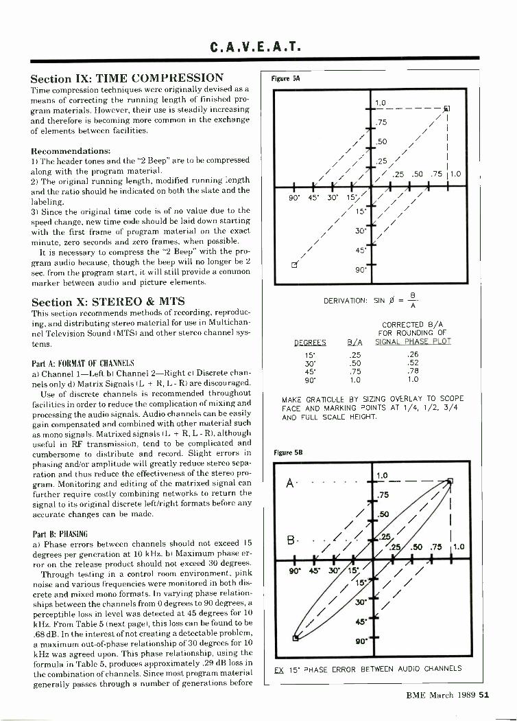
C.A.V.E.A.T.
Section IX: TIME COMPRESSIONTime compression techniques were originally devised as ameans of correcting the running length of finished pro-gram materials. However, their use is steadily increasingand therefore is becoming more common in the exchangeof elements between facilities.
Recommendations:1) The header tones and the "2 Beep" are to be compressedalong with the program material.2) The original running length, modified running lengthand the ratio should be indicated on both the slate and thelabeling.3) Since the original time code is of no value due to thespeed change, new time code should be laid down startingwith the first frame of program material on the exactminute, zero seconds and zero frames, when possible.
It is necessary to compress the "2 Beep" with the pro-gram audio because, though the beep will no longer be 2sec. from the program start, it will still provide a commonmarker between audio and picture elements.
Section X: STEREO & MTSThis section recommends methods of recording, reproduc-ing, and distributing stereo material for use in Multichan-nel Television Sound (MTS) and other stereo channel sys-tems.
Part A: FORMAT OF CHANNELSa) Channel 1-Left b) Channel 2-Right c) Discrete chan-nels only d) Matrix Signals (L + R, L - R) are discouraged.
Use of discrete channels is recommended throughoutfacilities in order to reduce the complication of mixing andprocessing the audio signals. Audio channels can be easilygain compensated and combined with other material suchas mono signals. Matrixed signals (L + R, L - R), althoughuseful in RF transmission, tend to be complicated andcumbersome to distribute and record. Slight errors inphasing and/or amplitude will greatly reduce stereo sepa-ration and thus reduce the effectiveness of the stereo pro-gram. Monitoring and editing of the matrixed signal canfurther require costly combining networks to return thesignal to its original discrete left/right formats before anyaccurate changes can be made.
Part B: PHASINGa) Phase errors between channels should not exceed 15degrees per generation at 10 kHz. b) Maximum phase er-ror on the release product should not exceed 30 degrees.
Through testing in a control room environment, pinknoise and various frequencies were monitored in both dis-crete and mixed mono formats. In varying phase relation-ships between the channels from 0 degrees to 90 degrees, aperceptible loss in level was detected at 45 degrees for 10kHz. From Table 5 (next page), this loss can be found to be.68 dB. In the interest of not creating a detectable problem,a maximum out -of -phase relationship of 30 degrees for 10kHz was agreed upon. This phase relationship, using theformula in Table 5, produces approximately .29 dB loss inthe combination of channels. Since most program materialgenerally passes through a number of generations before
Figure 5A
-..-
7"
1.0
.75 /.KI//
/ / /.50/ 7".//// // .25//
/ / 7"- / 25.50 .75 1.0
A AI I( V Vi,A90' 45' 30' 15' .// -.....l'/ -
/ / /_,, / // // ////1
3C//// 1
/ / 45'
Er 90'
DERIVATION: SIN 0 = -A
CORRECTED B/AFOR ROUNDING OF
DEGREES 13/A SIGNAL PHASE PLOT
.25 .2630' .50 .5245' .75 .7890' 1.0 1.0
MAKE GRATICULE BY SIZING OVERLAY TO SCOPEFACE AND MARKING POINTS AT 1/4, 1/2, 3/4AND FULL SCALE HEIGHT.
Figure 5B
A'"1"
1.0-----.75 /// .50/ 7" /
/I
B - . / '25// / '.25 .50 .75 1.01
r II r A/ A90' 45' 30' 15" / /
15' // // 30`'' // ..4/ 45'
L 90''
.EZ, 15' PHASE ERROR BETWEEN AUDIO CHANNELS
BME March 1989 51

C.A.V.E.A.T.
release, a 15 -degree maximum channel out -of -phase rela-tionship is recommended per generation. The additional15 -degree margin in the standard accounts for errors thatmay be encountered during final transmission.
Part C: MONITORING
All stereo material should be monitored aurally as well asvisually for mono compatibility and stereo imaging char-acteristics. The use of phase scopes or application of thegraticule, shown in Figure 5a, on a standard oscilloscope(X -Y feature) will quickly indicate the material's in -phaseand out -of -phase channel characteristics. Figure 5b illus-trates a 15 -degree phase error between audio channels.
Section XI: TEST TAPESThe objective of the committee was to establish a set ofrecommended alignment films and tapes for the profes-sional formats used in the exchange of recorded materials.
Recommendations:1) Audio Film Standards-35mm SMPTE (MF-35) 16mmSMPTE (MF-16) (NOTE: The 5 mil test films recorded at185 nWb/m were preferred over the 3 mil test films to aidin the detection and correction of head wrap problems andoverall tape path alignment.)*If not available, use Standard Tape Labs 35mm TestFilm.2) Audio Tape Standards-MRL Alignment tapes for ALLformats. A reference level of 250 nWb/m is recommended.NAB equalization should be used for 15 ips and AESequalization should be used for 30 ips. The exception tothis is 16 channel 1 -inch recording, where only IEC equal-ization will work on all machines.3) Videotape Standards (NTSC)-2-inch Quadruplex =Ampex and RCA Alignment Tapes (110 nWb/m)
Both manufacturers were chosen due to their inter-changeable nature. Although 2 -inch usage is diminishing,it is still a viable duplication and distribution format.
One -inch C Helical Reference Level = Ampex Full Trk.Audio Alignment Tape 100 nWb/m (part #1498600-03)Track Phasing, Head Height Frequency Response = SonyAlignment Tape (part #BR5-2 NTSC)
One -inch Type C helical recording is the predominantformat for editing and element exchange; however, somediscrepancies were found between manufacturer's align-ment tapes. Therefore, different tapes have been recom-mended for testing specific functions.
The Ampex Full -Track Audio Test Tape was chosen forreference level as it is the only test tape that specifies fluxdensity (100 nWb/m). This is the specified audio recordlevel for the 1 -inch Type C format.
Frequency response measurements were found to bemost consistent between samples of the Sony AlignmentTape. Use of the Ampex Full -Track Alignment Tape re-quired use of level correction factors for different frequen-cies. Although these were applicable to Ampex machines,the factors were found to be inaccurate on machines ofother manufacturers. Frequency response is to be adjustedwith the Sony Alignment Tape (part #BR5-2 NTSC).
Audio track phasing and head height adjustments arealso recommended to be done with the Sony Alignment
Table 5
Loss (db) at Sample FrequenciesFor A Given Phase Error at 10 kHz
15° 30° 45°
FREQUENCY (HZ) LOSS (dB)
1000 0.00 0.00 -.012000 D.30 0.00 -.025000 -.31 -.06 -.1610000 -.36 -.29 -.6812500 -.11 -.46 -1.0816000 -.18 -.28 -1.83
db loss 20 log['/ sin OZ + (cos; 0 + 1)2]
0=2nft
Tape (part #BR5-2 NTSC) due to the consistencies of thesamples.
Three -quarter -inch U-matic = 3/4-inch Sony AlignmentTape (part #RR5-4SB) 100 nWb/m
Sony and JVC alignment tapes were tested. For phasingtests, the Sony samples were consistent within 5 degrees.The JVC tapes showed sizeable errors. Sony produces theonly 3/4-inch test tape that specifies a reference level at10 kHz.
MII & Betacam = Equipment manufacturer's test tapesThe respective manufacturer's alignment tapes are rec-
ommended for their specific format.SummaryAlthough these findings are not definitive with regard totesting and alignment tapes, they will provide a basis forgood technical testing. Adherence to these recommenda-tions can reasonably insure a good interchange of tape andfilm media.
Section XII: MONITORING ANDACOUSTICSMonitoring systems are intended to accommodate accu-rate and consistent judgment when auditioning audio ma-terials. If the requirements for a good monitoring environ-ment are optimized, the user can be confident that what isheard is what is recorded. When certain requirements can-not be met, the user should be aware that those weak-nesses will limit the type of judgments that can be made.Recommendations:1) Signal to Noise-a) Room noise should be under NC 25.b) Maximum output should reach at least 110 dB SPLwithout clipping.2) Acoustics-a) Speakers and listeners should be awayfrom reflective surfaces. b) Speakers should be flushmounted (if designed that way). c) Listener should be atleast 5 feet from back wall.3) Electrical-a) Use short -run heavy gauge wire to con-nect amps to speakers. b) Use equalization cautiously. Tryto treat problems acoustically. c) If using SMPTE curve,make it switch-defeatable. SMPTE curve falls at 1.5dB/octave above 2 kHz and rolls off 6 dB/octave below100 Hz.
52 BME March 1989

Gold Standard.In finance, the gold standardmeans unquestioned securityand reliability. In broadcast -quality satellite receivers,it means the Agile OmniProfessional. From StandardCommunications.
Based on intelligent micro-processors, the Omni Prodoes most of the thinking foryou. You choose the desiredsatellite signal, and the OmniPro automatically sets thecorrect format of C or Kuband antenna inputs, full orhalf -transponder operation,center frequency, channelspacing, audio subcarrierfrequencies and more. Inessence, two knobs let youselect audio/video perfor-
mance without confusingconversion or referencetables, without complicatedswitches and controls, with-out hassle. But that's just thebeginning.
Order the optional RS -232computer remote controland you can change every-thing from the transponderbandwidth to the subcarrierfrequency, for a whole net-work or any individual unit,either by phone modem orEarth station uplink.
For broadcast applications,Standard offers the Omni Prowith the Broadcast Perfor-mance Package, which in-cludes proof of performance,EPROMs pre-programmed
for all domestic satellite for-mats and channels, multipleIF bandwidths, additionalaudio subcarrier demod-ulators, and more.
To get the full story, call orwrite Standard's SATCOMDivision.
And find out how littlegold it takes to get on theGold Standard.
StandardCommunicationsSATCOM Division
P.O. Box 92151Los Angeles, CA 90009-2151Telephone: (800) 243-1357In California (800) 824-7766(213) 532-5300 Telex: 67-7173
Circle 118 on Reader Service Card Page 63

Introducing the smallest,lightest broadcast Betacam®camcorder in the world.
The BVW-200 weighs only15 pounds, including lens, cas-sette, viewfinder, and lightweight
battery. So you can hold anyshot better and longer. Plus, itrecords for an entire hour on asingle NP -1A battery.
But state-of-the-art featuresare what make the BVW-200
extraordinary by any standard.Betacam SP® format. AdvancedCCD technology for higher sen-sitivity, resolution of 550 lines,and a superior S/N ratio. There'seven viewfinder playback.

RAISES TV JOURNALISM TO NEW HEIGHTS.
And all of this fits into a 15 -inch length. And a low profile forunobstructed peripheral view.The BVW-200. More compactand maneuverable than any oth-er camcorder before it.
Suddenly, the impossibleshot is yours. To find out how the
SONYBVW-200 can help your workreach new heights, see your SonyBroadcast Sales Engineer. Orcall: (800) 635 -SONY.Sony Communications Products Company, 1600 Queen AnneRoad, Teaneck, NJ 07666. © 1989 Sony Corporation of America.Sony, Betacam and Betacam SP are trademarks of Sony.
BROADCAST PRODUCTS

C.A.V.E.A.T.
4) Stereo-a) Speakers should be maximum of 60 degreesapart. b) Room should be symmetrical.5) Monitoring Practices-a) Check mixes on big and smallspeakers at loud and soft levels. b) Check stereo materialin mono and stereo over two speakers. c) Check mono ma-terial over one speaker.
Part A: SIGNAL TO NOISEThe signal-to-noise ratio of a listening room needs to ex-ceed that of the recording medium used. The power ampsshould also provide more signal than will ever be requiredduring a session.
A noise level of NC 25 is a practical level. This can bemeasured on meters made by Ivie, GenRad, Bruel & Kjaerand others. As a quick noise level test, if you cannot hearyour fingers rubbing together while your arm is at yourside, the noise level in the room is at least 10 dB too high.
At NC 25, with 0 VU set to be approximately 85 dB SPL,noises recorded at -60 VU will be audible. To achieve thisenvironment, noisy equipment (with spinning heads orfans) should be removed from the listening environment.Audio monitoring in a machine room should be restrictedto confirmation of program content, not audio quality.
A sound system should be able to achieve at least 110 dBSPL without clipping or other unwanted sounds, thus al-lowing material to be played reasonably loud withouttransients being clipped off. This measurement should bemade with C weighting and the meter set to "fast" speed.The meters mentioned above, or an inexpensive SPL me-ter (such as can be obtained from Radio Shack), will pro-vide this measurement. The clipping point can be deter-mined by observing indicators on the power amp (ifavailable), closely watching for flat tops or bottoms of thepower amp output waveform on an oscilloscope, or by lis-tening for harshness in the sound that is level dependent.
Part B: FREQUENCY RESPONSE
Several factors determine the frequency response of aroom. Unfortunately, there is no real agreed -upon way tomeasure this response. There are three primary groups ofinteracting sounds that must be measured: direct soundfrom the loudspeaker(s), a few early reflections and thegeneral diffuse or reverberant sound. Equipment that sep-arates these sounds is relatively expensive and complex tointerpret. Due to the complexity of the response and itsmeasurement, the committee did not make specific recom-mendations on what room responses are appropriate.There are, however, several ways to control frequency re-sponse: speaker selection, room treatment and electricaltreatment.
Part C: LOUDSPEAKER SELECTION
Loudspeakers should have reasonably flat on -axis fre-quency response and be free of resonances. They shouldalso have adequate power handling and reliability. Sev-eral popular monitors are listed in Table 6.
There are also two categories of speakers listed: mainmonitors and near field monitors. Near field monitors areuseful because they remove most of the effects of the roomacoustics. Near field monitors also serve as an alternativereference. Due to their often limited bass response and
power handling, however, they should not be counted on tocompletely replace the main monitors.
Some Popular Professional Loudspeakers Main Monitors
COMPANY
B&W
JBL
Tannoy
UREI
Auratone
Electro-Voice
MDM
Yamaha
MODEL NUMBER COMMENTS
808 Not appropriate forall applications.
4400 4300 series no longerseries recommended.
S.G.M. series New, not thoroughlytested.
800 series In many music rooms.
Near Field MonitorsSC Standard limited
fidelity reference.
EV100EL Self -powered version.
TA2, TA3
NS10 Popular in music
studios.
Part D: ACOUSTIC TREATMENT
The position of the loudspeaker strongly affects its sound.Most large monitors are designed to be flush -mounted inthe wall. Failure to do this can cause two problems: 1) thelack of acoustic loading from the wall will cause roughly a3 dB drop in the bass response, and 2) there will also be aseries of dips in the frequency response due to the soundreflecting off the wall behind the speaker. These notcheswill be at 282.5/(D N) in Hz, where D = distance to wall(feet) and N = 1, 3, 5...
Large objects close to the speaker will also cause reflec-tions that will interfere with the frequency response.These reflections will cause a series of dips in the fre-quency response (known as comb filtering) just as reflec-tions in a video cable do. Controlling these reflections canbe an economical way of improving the sound of a room.
The following test will locate interfering surfaces. Whileplaying pink noise over a speaker, have an assistant coverup possible troublesome surfaces with Sonex or equivalentsound absorbing material. If the sound at the listeningposition changes, the speaker or surface should be moved.Otherwise, the surface should be treated with sound ab-sorbing material (preferably not carpeting). Owens-Cor-ning 703 insulation is an effective absorber, but it is not aseffective as Sonex at grazing angles of sound incidence. Toaim the speakers, point the tweeter towards the listeningposition. This will provide maximum high frequency re-sponse.
The listening position should not be too close to objectsthat will reflect sound back to the listener. Troublesomesurfaces can be treated as described above. The listeningposition should be at least five feet from the back wall.This will prevent sound reflecting from the wall from caus-ing serious notches in the bass response.
If the listening position is less than five feet away from
56 BME March 1989

C.A.V.E.A.T.
the wall, the wall should be made as sound absorbent aspossible. This is difficult since most acoustic materials ab-sorb poorly in the bass region. If Reflection Free Zonemonitoring is desired, the listener should be closer to thespeaker than any untreated reflective surfaces.
In general, the larger a room and the more diffusingsurfaces, the smoother the frequency response of the de-caying reverberant sound, especially in the bass region.The room should also be tested for flutter echoes. This canbe done by walking around the room, clapping one's hands,and listening for a buzzy type of echo. These echoes notonly color the sound, but will also affect speech intelligibil-ity.
Since a comprehensive overall room treatment is beyondthe scope of this paper, an acoustic specialist should beconsulted if serious changes are being made to a room.
Part E: ELECTRICAL TREATMENT
There are two aspects to electrical treatment; preservingthe signal and intentionally altering it. Make sure that allspeakers are wired with the correct polarity. Failure to dothis will result in reduced bass and lack of any phantomcenter in the stereo image.
The wiring between the amplifier and the speakershould be kept short and of the heaviest gauge practical. Ifthe wire is undersized, the damping factor of the poweramplifier is defeated. This results in flabby bass and in-creased overshoot in the speaker cones. Good speaker wireis an inexpensive way to improve the performance of asound system.
Wire with a large number of strands is more flexible andmakes better contact with connectors. To connect heavygauge wire to equipment, it is suggested that spade lugs besoldered to the cable. This provides a reliable low resis-tance connection that fits all amplifiers and most speak-ers. Below is a table that shows the different lengths ofcable that have the same resistance.
Gauge and Length Equivalents
CABLE LENGTH IFT) WIRE GAUGE
20.0 10
14.5 12
8.5 14
5.5 16
Length and guage combinations which preserve an amplifier damping fac-tor of 100 with 4 Ohm speakers.
After speakers are mounted and the room treated, elec-trical equalization may be desired. The abilities of equaliz-ers have been widely oversold. Equalization does not fix:comb filters, deep notches in frequency response, poorsound diffusion, room reverb time, stereo imaging, sharpresonances in the room or speaker, and many other prob-lems. EQ does control the total energy put into the room bya speaker and can be used to adjust the frequency responsein one area of the room, with the risk of misadjusting theresponse in another area.
If an omnidirectional microphone is used in conjunctionwith a 1/2 -octave analyzer, the loudspeaker responseshould not be adjusted to measure flat. Some roll -off
should be expected at high frequencies. The microphone isresponding to indirect sounds, as well as the direct sound.These sounds will have a high frequency rolloff dependenton the wall construction.
SMPTE has a standard for monitor system electro-acoustic response in television control rooms (SMPTE222M). It consists of a 1.5 dB/octave rolloff starting at 2kHz. There is also a bass rolloff of 6 dB/octave below 100Hz. There is an overall tolerance of roughly +/- 3 dB. Itwas the opinion of some members of the committee thatthis curve included too large a rolloff. The -3 dB points of63 Hz and 8 kHz do not reflect the response of high -qualityconsumer listening rooms. If such a curve is used to equal-ize a room, it is recommended that the equalizer bedefeatable by the use of a switch.
Part F: STEREO IMAGINGThe maximum recommended angle for speaker separationis 60 degrees. Angles much smaller than this will make itdifficult to judge the stability of the phantom center im-age. Angles any larger than this may destroy the centerimage in the monitoring room. The 60 degree angle meansthat the listener and the speakers are equally spaced fromeach other. The speaker placement should be chosen sothat the room will be acoustically symmetrical from left toright. This will ensure that the sound will not change as itis panned from one speaker to the other.
Part G: MONITORING PRACTICESAll mono material should be listened to using just onespeaker at a time. An additional speaker only detractsfrom the sound quality. All stereo material should bechecked in mono (L + R) mode. Since 90 percent of theaudience is listening in mono, it is imperative that mate-rial be checked for mono compatibility. Problems such ascancellations due to polarity or phase errors, or centerchannel build up can be detected using this technique.When switching back and forth between mono and stereomode, it is less distracting if two speakers are used in bothmodes. If a center speaker is used for mono compatibilitychecks, it should be the same model as the stereo speakers.All mixes should be checked on the main monitors and ona limited fidelity speaker such as the Auratone. Mixesshould also be checked at a variety of listening levels. Thisprocedure will better assure compatibility with a varietyof home listening systems.
GLOSSARY OF TERMSALIGNMENT TAPE: A tape recorded with calibrated sig-nals made under laboratory conditions, and checkedagainst a standard for the purpose of maintaining equip-ment.ASYNCHRONOUS: Not having the exact same rate asother units; "Wild".AZIMUTH: The rotation of the tape or film head whichadjusts the head gap to be perpendicular to the direction ofthe tape/film travel. This gives the best high frequencyresponse, as well as the correct timing and phase relation-ships between the channels in the head (see HEAD
BME March 1989 57

SEE US AT NAB BOOTH #3955

Canon Answers the Needs of theBroadcast Industry Once Again.
Introducing the Canon J50X9.5BIE.Canon answers the demanding requirements of
electronic field production with the sensational newJ50X9.5BIE. The perfect lens for outdoor events likethe Super Bowl and the Calgary Olympics where theJ50X was put into action. Featuring a 50X zoom ratio,f1.4 maximum aperture, and an effective focal lengthof 9.5 to 950mm, thanks to its built-in 1.5X and 2Xextenders. Any way you look at it, the J50X9.5 givesyou incredible reach. Yet, it's great indoors too, with aminimum object distance of 7.2 feet and macrofocus-ing to 20 inches. Plus the usual high M.T.F., minimizeddistortion and chromatic aberration you've come toexpect from Canon broadcast lenses.
An optional rotary shutter provides a choice of
1/1,000th, 1/500th and 1/250th sec. high shutter speedsand will interface with most major manufacturer'scameras.
The J50X9.5BIE is designed for outstanding per-formance on both 2/3" tube and CCD cameras. Andwith a weight of just 36 lbs., these credentials are evenmore impressive. Simply stated, the J50X representsthe most advanced design in optical technology avail-able to the broadcast industry today. There is no betterlens to meet the tough professional standards of elec-tronic field production. So the next time you need abroadcast lens with the reach of a 50X zoom and unsur-passed optical quality, choose Canon. Because noother lens measures up.
Ca -nomCanon USA, Inc., New York Office: One Jericho Plaza, Jericho, NY 11753 (516) 933-6300. Dallas Office: 3200 Regent Blvd., Irving, TX 75063 (214) 8349600
Chicago Office: 100 Park Blvd., Itasca, IL 60143 (312) 250-6200. West Coast Office: 123 Paularino Avenue East, Costa Mesa, CA 92626 (714) 979-6000Canon Canada. Inc., 6390 Dixie Road, Mississauga, Ontario L5T1P7, Canada (416) 678-2730
Circle 119 on Reader Service Card Page 63

C.A.V.E.A.T.
WRAP).BLANKING LEVEL: The zero signal level in a compositevideo signal. Below this is sync information, above this isvisible picture.CAVEAT: Concerned Audio and Video Engineers andTechnicians: A Chicago -based group of professionals work-ing to provide recommended procedures and engineeringguidelines to improve the quality of audio for the visualmedium (c/o 770 N. LaSalle, Chicago, IL 60610).COUNTDOWN: A special leader, where the time remain-ing to program start is displayed. This has been standardpractice with film, and is recommended for video as well.The film "Academy Leader" has an 8 sec. countdown, but 5sec. is appropriate for video.DIGITAL (AUDIO): A signal where the audio waveform isencoded into binary numbers for processing or storage.This is a robust signal that can be copied repeatedly with-out degradation.DISTORTION: An unwanted change in signal. It can beclassified as frequency, phase or non-linear, although usu-ally non-linear is meant. Non-linear distortion is usuallymeasured as harmonic or intermodulation. Non-linear dis-tortion has an "edgy" or "grungy" sound.DOUBLE SYSTEM RECORDING: A production methodwhere the picture and the sound are recorded on separatemachinery by separate people on separate media. This al-lows a higher quality recording of the sound, at higherexpense. Great care must be taken to see that sound andpicture remain synchronous.DROP FRAME: (see TIME CODE)DROPOUT: A momentary reduction or loss of signal. Usu-ally used in reference to tape or film.DUAL CHANNEL MONO: (see MONO)DUBBING: 1) Making an identical copy of a recording. 2)Lip -syncing.DYNAMIC RANGE: 1) The difference (in dB) between theloudest and softest portions of the program. 2) The differ-ence (in dB) between the maximum permissible level andthe noise floor of a piece of equipment (see HEADROOMand SIGNAL-TO-NOISE).ELEMENT: A recording that is only one piece contribut-ing to a finished product.ELEMENT, N -CHANNEL: An unmixed multi -channelrecording, or a submaster.EQ-EQUALIZATION: The action of modifying a signalby amplifying with a different gain or loss at differentfrequencies. Equalization is also used in tape machines toovercome losses in the recording processes.FIELD (VIDEO): One half (every other line) of a singleNTSC television frame.FLUX DENSITY: The strength of a magnetic field. Intape recording, the standard units are expressed innanoWebers per meter (nWb/m). The standard units, how-ever, are defined slightly differently by the ANSI and theIEC. The ANSI definition yields level readings that are .8dB lower than the IEC definition for a given recording.The ANSI units are used by CAVEAT and SMPTE.FRINGING: A magnetic phenomenon where the multi-channel audio head picks up signal beyond the track edgesat low frequencies. Test tapes are usually made with asignal spanning the entire width of the tape, including the
area between tracks. When these tapes are played back ona multi -channel head, the low frequency tones will appearto be louder than they actually are.FULL COAT/STRIPE: Film magnetic recording stockcomes in two types. Full coat stock has oxide coated acrossthe entire width of the film. Stripe stock has oxide just inthe area where the monophonic recording takes place, anda narrower stripe called the balance stripe towards theopposite edge of the film. The balance stripe provides uni-form thickness, and should not be used for recording; therest of the film is transparent.HEADER: The leader at the beginning of a recording,before the program starts.HEADROOM: The difference in dB, between the maxi-mum permissible level and the reference level. In taperecording, the difference between 0 VU and the 3 percentharmonic distortion point. Headroom is roughly 8 dB with1 -inch videotape, and 12 dB with audio tape at 15 or 30 ipsor 35mm film.HEAD HEIGHT: An adjustment of a magnetic head tocenter a channel of the head on a track of a tape. Improperheight will lead to level loss and incomplete erasure whenexchanging materials on other machines.HEAD WRAP: A rotation of a magnetic head to ensureintimate contact of the head gap with the tape recording.Improper wrap will cause a higher incidence of dropouts,and high frequency loss. When wrap is set correctly, thehead wear pattern will be symmetrical on both sides of thehead gap.HEADS OUT: The tape is positioned on the reel so thatthe program plays without rewinding; recommended forvideotape storage.HUB IMPRESSIONS: 1) Tape damage caused by irregu-larities in the tape reels. 2) A physical impression made intape which will cause recording and/or playability prob-lems due to the irregular tape to head contact.IRE: Institute of Radio Engineers; also, a unit of videosignal amplitude. One hundred IRE equals approximately.714 V.ITS: International Teleproduction Society headquartersare at 900 Avenue of the Americas, Suite 21E, New York,NY 10018LEVELS (AVERAGE): A number numerically or physi-cally arrived at by summing a number of level readingstogether and then dividing by the number of readings.Averaging meters will not reflect the true level of shortpeaks, but will respond higher than a VU meter. Averag-ing to sort -of -peak responding meters are often found inthe audio section of VTRs, while true VU meters are oftenfound in audio consoles and professional audio recorders.LEVELS (PEAK): The maximum instantaneous level (seePEAK).LINE, HORIZONTAL (VIDEO): 1/525 of a video frame;approximately 63.5 pisec.MASTER: An original recording. Almost meaningless un-less used with a descriptive qualifying term. One person'smaster is often the next person's element.MASTER, DUPLICATION OR DUBBING: Can be theEdit Master or a copy of the Edit Master made specificallyfor the duplication process.MASTER, EDITED: The first generation of a fully edited
60 BME March 1989

C.A.V.E.A.T.
videotape.MASTER, FILM -TO -TAPE: The first generation tape re-cording from a film.MASTER, MULTI -TRACK: 1) Unmixed original multi-channel recording. 2) (see MASTER, N -TRACK/CHANNEL).MASTER, MUSIC: The mixdown of multi -track music re-cording or an edited version, such that it becomes a masterin its own right.MASTER, N-TRACK/CHANNEL (2-Trk, 3-Trk, etc.): Amulti -channel recording made such that, if all N channelsare summed, each with unity gain, the final mix will beobtained.MASTER, ORIGINAL: A first generation recording.MASTER, PRODUCTION: The finished recording, readyfor duplication.MASTER, PROTECTION: Preferably called a Safety. Acopy of a master to be used if the working master is dam-aged.MASTER, SUB: (see SUBMASTER).MASTER, SYNC OR PULSED: The first generation of anaudio tape to receive pulse or time code, which should beused for any future sync transfers.MONO, DUAL CHANNEL: A recording where a redun-dant copy of a monophonic signal is placed on anotherchannel. The primary purpose of the second channel is as abackup copy. The two tracks should not be summed to-gether, since phase differences normally occurring be-tween the channels might lead to high frequency signallosses.MONO, FULL TRACK: A monophonic recording made ona monophonic 1/4 -inch tape recorder across the full width ofthe tape.MONO, HALF TRACK: A monophonic recording made onone channel of a 2 -channel 1/4 -inch recorder. Pulse or timecode is usually placed on the other channel.MTS-Multi-channel Television Sound: A system of stereoaudio, compatible with the monophonic NTSC system. Itconsists of a pair of 15 kHz bandwidth channels for stereo(L + R, L -R), an 8 kHz bandwidth separate audio programchannel (SAP), and a narrow bandwidth professional us-age channel. A dbx-licensed noise reduction system is usedto improve perceived signal to noise ratio.NC-Noise Contour: A set of criteria used to assess thequietness of a room. Measurements of acoustic noise aremade using octave -wide filters. These are then comparedwith the NC curves to an NC rating for the room. For agiven NC rating, higher levels of noise are allowed atlower frequencies. This is to match the lower sensitivity ofthe ear at low frequencies, especially for audio at low loud-ness.NEOPILOT: Trademark of Kudelski (see PULSEDTAPE).NEAR FIELD MONITORS: A speaker developed to beused in close proximity to the user so that room acousticshave little effect on the sound.NON -DROP FRAME: (see TIME CODE).NR-Noise Reduction: A system where the noise is re-duced, usually through a complementary encoding and de-coding process. The signal is encoded through the use ofvarying gain boost and equalization, in order to put the
maximum allowable energy onto tape. The decoder thenattempts to return the signal to its original form, therebyhiding the noise. Available types of NR include Dolby A,B, C and SR; dbx Types I and II; Telecom C4 and others.nWb/m-NanoWebers per Meter: (see FLUX DENSITY)OCTAVE: A musical interval spanning eight full tones.This is a 2:1 span of frequencies. Human hearing spans tenoctaves. One-third octave is a ratio of 1.26:1.OMNIDIRECTIONAL MICROPHONE: A microphonethat is equally sensitive to sounds coming from all direc-tions. A test microphone should have a maximum diame-ter of 1/2 -inch to be truly omnidirectional.PEAK METER: A meter that is of the instant recordingtype. An ideal meter would have an instantaneous risetime, with a much slower fall time, in order to give the eyetime to read the peaks.PEAK PROGRAM METER: A meter as defined by theIEC that has a peak response designed to match humanhearing. Its response is 1 dB down with a 10 millisecondburst compared to that with a steady state tone. The re-sponse is lower with shorter peaks. This is designed tomatch the time it takes the ear to detect distortion.PHASE: Used to indicate a time delay of one signal rela-tive to another. Pure time delay will cause a phase shiftthat is linearly increasing with frequency. Phase shiftsthat are not linear are called phase distortion. Summing adelayed signal with the original one will result in a fil-tered version, referred to as phasing or flanging. The termphase reversal is often improperly used to mean polarityreversal (see POLARITY).PHASE SCOPE: Form of oscilloscope having the ability toshow phase relationships between the audio signals.PINK NOISE: A random signal with equal energy in eachoctave. The energy distribution makes it a very usefulaudio test signal for checking frequency and phase re-sponse. Its random nature also makes it representative ofactual program conditions. Pink noise is often generatedby filtering white noise with a filter that has a slope fall-ing at 3 dB/Octave (see WHITE NOISE).POLARITY: The property of a signal describing whetherits waveform is upright, or inverted (flipped) about itsaxis. Correct polarity is defined such that positive air pres-sure towards the microphone will create a positive voltageon pin 2 of the 3 pin XLR connector or the tip of a 1/4 -inchphone plug. This will in turn be amplified and become apositive signal to the speaker which will cause the cone tomove towards the listener. There is also a new SMPTErecommended practice (RP 134) describing polarity onmagnetic recordings.POLARITY, RELATIVE: Polarity of one channel withrespect to the other. An inverted relative polarity willdestroy stereo imaging and perceived bass response.PRE -ROLL: The time or tape allowed before the start ofprogram for equipment to come up to play speed or tosynchronize.PRINT -THROUGH: The inadvertent magnetization ofadjacent tape layers causing pre -echo in tapes storedheads out, and post -echo in tapes stored tails out.PULSED TAPE: An audio tape with a speed referencesignal consisting of a reference tone. A pulsed mono 1/4 -inch tape has a 60 Hz tone recorded on two narrow tracks
BME March 1989 61

C.A.V.E.A.T.
of opposite polarity such that the pulse is inaudible whenplayed on a Full -Track mono audio head. A 60 Hz tone canbe recorded on an audio channel on multi -channel ma-chines. The speed reference signal can be used to dub ortransfer the tape onto sprocketed film or time coded tapefor editing.RMS-ROOT MEAN SQUARE: A method of measuringlevel where the true power of a signal is calculated. It isusually used to specify noise signals. Short spikes or peaksin the signal have only a small effect on long-term read-ings. The signal is squared, the average taken, and thesquare root is taken (see LEVELS).RUN -UPIRUN -OUT: The blank tape or film used forthreading at the beginning and end, respectively, of a re-cording. No test signals or program should be recorded onit.SAFETY (ALSO PROTECTION MASTER): A copy of anoriginal recording. Since the quality is usually inferior tothe original recording, this is not the recording that shouldbe used in the process of finishing a project.SATURATION (AUDIO): The recording level on analogtape where the third harmonic distortion reaches 3 per-cent. At high frequencies, the third harmonic would beoutside the bandwidth of the recorder, so it is the levelwhere the sensitivity of the recorder drops 1/2 dB (the levelcompression effect).SIGNAL TO NOISE-SIN: 1) (preferred) The difference,in dB, between the maximum permissible signal level andthe noise that is present while the maximum signal ispresent. 2) The difference, in dB, between the maximumpermissible signal level and the residual noise. 3) Thedifference, in dB, between a given signal level and theresidual noise.SMPTE: Society of Motion Picture and Television Engi-neers, 595 West Hartsdale Avenue, White Plains, NY10607-1824SMPTE TIME CODE: (see TIME CODE).SPL-Sound Pressure Level: A measure of the loudness ofan acoustic sound, expressed in dB. 0 dB SPL is near thethreshold of hearing. 65-80 dB is normal conversationlevel, 120 dB peaks are reached in live music, and 130 dBis the threshold of pain.SPLIT TRACK(S): (see N-TRACK/CHANNEL MAS-TER).STEREO IMAGING: The ability to create stable and be-lievable illusionary sound sources using a stereo audiosystem.SUBMASTER: A partially mixed or edited recording usedto create a master.SUMMING (OF CHANNELS): A simple electrical addi-tion of channels, usually a unity gain, with no furtherprocessing; differs from a mix in that no gain adjustmentsare made during the summing process.TAILS OUT: The tape is positioned on the reel so thatrewinding is necessary prior to playing; often recom-mended for audio tape storage.TAKE NUMBER: A sequential numbering of the at-tempts to record a given scene or segment; not necessarilythe same as a track number on a specific tape reel.TIME CODE, ASCENDING: A code where the numberingincreases with time, and no numbers are repeated within a
reel of tape or film.TIME CODE, CONTINUOUS: A time code that has notbeen edited. The frame numbering counts in simple fash-ion with no jumps in numbering (except those allowed byDrop Frame) and no pauses, repeats or interruptions.TIME CODE, ROP FRAME: A SMPTE Time Codewhich drops frames ":00" and ":01" each minute, exceptevery tenth minute, to allow a 29.97 frame/sec (NTSC)frame rate code to keep a count matching real clock time.TIME CODE, LONGITUDINAL: A code that is recordedon an audio channel; although difficult to read at slowspeeds, it can be read at very high wind speeds. It can alsobe recorded at any time, since it is independent of thepicture and audio channels. Its disadvantage is that it tiesup one of the audio channels and is prone to dropouts atlow tape speeds; it must be processed before it is copied toanother tape.TIME CODE, NON -DROP FRAME: A SMPTE Time Codewhere the frame numbering is sequential, with no droppedframes.TIME CODE (VITC), VERTICAL INTERVAL: A SMPTETime Code that is recorded in the non -display portion ofthe video picture. This code has the advantages of beingreadable at still frames and very low speeds, and is read-able as long as the picture quality is good. It has the disad-vantage that it cannot be added after the picture is re-corded.TIME CODE, WINDOW: A recording where frame num-bering is visible in the television picture. This is not ma-chine-readable code, and cannot be used by an electroniceditor or synchronizer; also called Visible Time Code.TIME COMPRESSION: A technique where the playspeed of a recording is increased above the recorded speedto shorten the duration of a recording. Normally, a pitchchanging device is used to lower the resultant pitch backto normal, in order to prevent a "chipmunk" effect onvoices.TWO BEEP/2 BEEP: A one frame long tone burst, using atone of 1 kHz. It should occur 2 sec. before program start; isused to mark synchronization between audio and visualportions of a program.V DRIVE: Vertical Drive: A pure tone with a frequencyequal to the field rate. It is 59.94 Hz with the NTSC signal.VITC: Vertical Interval Time Code (see TIME CODE).VU METER-(VOLUME UNIT): A metering system thatis intended to indicate the perceived loudness of a signal.The meter should reach 99 percent of the steady tone read-ing when a 300 millisecond tone burst is applied. An over-shoot of 1.5 percent is allowed. There are many metersmarked in VU units that do not meet the above criteria;they are often too fast and too bouncy. When in doubt, askthe manufacturer.WOW AND FLUTTER: The speed variation of a recorderor reproducer expressed in percent. Slow changes of speed,such as an off -center record, are called wow. Fasterchanges are called flutter. Quad videotape -based cartridgeplayers are notorious for having quite audible flutter if notmaintained properly.WHITE NOISE: A random signal with equal energy perunit bandwidth. This form of noise occurs naturally intransistors and resistors.
62 BME March 1989

RADIO ENGINEERINGNUMBER SIX SPECIAL SECTION MARCH 1989
RDS Radio Comes On -Stream inEurope
Aconsortium of European radio broadcastersmounted a major demonstration of RDS (Ra-dio Data System) capabilities at the interna-tional MIDEM Radio Conference held inJanuary in Cannes, France. First generationRDS radios are now becoming available
throughout Europe, according to the EBU RDS ProgramExperts Group, which made the presentation.
RDS is the result of a 15 -year European research anddevelopment program to formulate a standardized sys-tem to add data to VHF/FM radio transmissions. Thesystem was initially devised as a method for displayingthe name of stations being received in order to make iteasier to locate them on Europe's increasingly crowdedFM waveband.
Current applications for RDS include station identifi-cation and transmission signal locking, format codingand an automatic travel information alert which also in-terrupts in -car cassette listening. RDS can also providesupplemental text to radio listeners via a homecomputer.
The standardized RDS system was developed by agroup of broadcasters appointed by the European Broad-casters Union. Participants were the British Broadcast-ing Corp., IRT (Germany) and Swedish Telecom Radio.
MIT ProfessorSlams FMStereo, FMXThe results of a joint re-search project between theMassachusetts Institute ofTechnology and the BoseCorp. call into seriousquestion the quality of FMstereo, FMX and SCAbroadcast signals in thepresence of multipath dis-tortion.
Based on a mathemati-cal model and a field testat MIT college radio sta-tion WMBR-MIT, the re-sults are contained in apaper called "A Theoreti-
cal and ExperimentalStudy of Noise and Distor-tion in the Reception ofFM Signals." It was re-leased at a "semi-publicgathering" January 25 atMIT's Media Lab in Bos-ton, MA.
The study analyzed theeffects of multipath on anyanalog modulation of anFM carrier. Based on astudy of both FM stereoand FMX, a method of FMstereo broadcasting de-signed to minimize thestereo noise penalty infringe areas, it concludesthat broadcast station areacoverage is decreased by
the FMX system. It fur-ther concludes that FMXtransmission degrades re-ception on existing FMstereo receivers. The studyalso states that FMX re-ceivers are inferior to ex-isting FM stereo receiversfor receiving FMX trans-missions.
"The FMX system wasoriginally designed to im-prove a second order prob-lem of the existing FMstereo system," said Dr.Amar Bose, who is a pro-fessor at MIT. Bose is alsochairman of the privatelyheld Bose Corp., a manu-facturer of consumer high-fidelity products. The BoseCorp. is also an OEMjoint -venture partner withcar stereo manufacturerDelco Electronics. Thepartnership supplies carstereo systems to GeneralMotors Inc., and to Nissan,Audi and Honda. TheFMX system was not "sin-gled out" for specialexamination but offeredmerely as "an example,"Bose said.
"Nothing in their math-ematics reflects the FMXequation," said EmilTorick, president of Broad-cast Technology Partners,Greenwich, Co. "Lord Kel-vin had a mathematicalmodel that proved heavier-than-air machines couldn'tfly." BTP was formed to li-cense and develop theFMX system when theCBS Technology Center,which originally developedit, was closed in 1986. Ex-ecutives of BTP weregranted special permissionfrom the Office of thePresident of MIT to attendthe presentation and par-
ticipated in a bitter Q&Asession. "This is an imped-iment and a distraction toour efforts," Torick said,"but there is so muchmerit in FMX that we be-lieve it will succeed re-gardless of what Dr. Bosesays."
Over 100 commercialand educational FM sta-tions are currently com-mitted to broadcasting inFMX. Both JVC and carstereo maker Alpinelaunched FMX products atthe Winter ConsumerElectronics Show early inJanuary; FMX ICs aremade by Sprague andSanyo. Motorola recentlyannounced manufacturingplans.
The timing and contentof the presentation hasaroused industry specula-tion that new receiverproducts incompatiblewith the FMX system maybe in development. "IfFMX doesn't work, it willdie on its own," said oneindustry analyst. "It's SCAthat needs to be throt-tled-why didn't they ex-amine that?"
BTP says it is develop-ing its own data and willrebut the Bose/MIT studyshortly.
CONTENTSRadio News 67
ImprovingRENG 68
Efficient AntennaDesign 73
BME March 1989 67

IMPROVED R-ENG USINGrve
changes to the broadcast in-dustry brought about by the di-estiture of AT&T caught many
by surprise. Immediate program cir-cuit rate increases of 300 percent ormore were common. Installationcharges soared as much as 1000 per-cent. Subsequent hikes made matterseven worse.
It didn't take long for the effects ofthis cost -spiral to reach the airwaves.Fewer remotes (or "outside broad-casts" [OB]) and more dial -up audiowere its symptoms at most stations.More RPUs were put into use bybroadcasters able to license and affordsuch an investment, primarily in lo-cations where terrain wouldn't pre-clude their use. In many markets,however, RPU frequencies areshared. This reduces their flexibility,especially at breaking news events.
Compromise resulted in greater re-liance on the dial -up system for audiofeeds. Service area was almost uni-versal, no lead time was required inmost cases and costs were minimal.But audio quality suffered terriblydue to reduced bandwidths, higherdistortion and greatly increasednoise.
The recent development of the cel-lular telephone and bandwidth exten-sion systems reduce the various com-promises broadcasters must make inthe R-ENG/OB matrix. But thesehave also increased choices whichmust be made. (Table I)
Bandwidth extension systems arean interesting and elegant method ofsqueezing the most audio quality outof the dial -up network. Three manu-facturers currently make up the mar-ketplace, which is an area that is stilldeveloping. All three share relativelysimilar techniques in accomplishingtheir objective, to wit, wider fre-quency response and in some cases
68 BME March 1989
DIAL-UP LINESThe economics of R-ENG and other radio remoteshas changed dramatically since the AT&Tdivestiture. Using frequency shifters to improvethe fidelity of dial -up lines can save time, moneyand audio quality.
lower noise levels than dial -up trans-mission. Add to this quality improve-ment AT&T's recent decision to cutback inter -city terrestrial servicedrastically and these devices becomeeven more valuable.
Bandwidth extension systems uti-lize an encode/decode approach, shift-ing frequency bands on the transmitside and unshifting them on receive,via a single-sideband suppressed -car-rier heterodyning process. This is setup so that the actual frequencies thatpass through dial -up phone lines canextend beyond their typical one de-cade (300 to 3000 Hz) response. Ofcourse, the lines' response isn't reallychanged. Rather, their cutoff frequen-cies are, in effect, moved, thereby wid-ening frequency response subjectivelywhen perceived by the human ear. Atypical single -line system will upshiftaudio by 250 Hz on transmit anddownshift by the same amount on re-ceive, so that the effective bandpass ofthe line is 50 to 2750 Hz. Note thatalthough the bandpass is still 2700 Hzwide, the low frequency cutoff has
BY SKIP PIZZI
been extended by nearly three oc-taves, at the expense of a one -sixthoctave loss on the high end.
For applications that don't requirereal-time feeding or live airing, a sin-gle -line frequency shifter can be ofeven more value when used with"half -speed transmission." Here, a re-cording is made in the field, thenplayed back through a frequencyshifter at half its original recordingspeed. At the receive end, this half -speed audio is shift -decoded and re-corded, then played back at double -speed. This provides a single octavetradeoff in the bandpass of the line,gaining an octave on the high endwhile losing one on the low end. Try-ing this without a frequency shifteron a dial -up line provides unaccept-able results, due to the low -frequencycutoff of 600 Hz. With the additionaloctaves on the low end that frequencyshifting provides, however, there ismore than enough energy to spare anoctave there in order to gain one atthe high end.
Remember that the more subjec-tively important high end is not ex-tended by a single -line frequencyshifter. With half -speed transmission,

the 50 -to -2750 Hz bandwidth of thefrequency -shifted line translates to100 to 5500 Hz. Note that this ap-proximates the response of a 5 kHzprogram circuit and provides a muchbetter tonal "balance" to voice trans-missions than does the real-time fre-quency -shifted approach. Since add-ing low end to a dial -up line withoutproportional high end increase may infact do more harm than good, someusers will only use single -line shifterswhen half -speed transmission is alsopossible. (An old guideline from theearly days of telco is the "Rule of400,000," which states that inbandlimited conditions, to maintainthe proper tonal balance required foroptimum intelligibility, any two cut-off frequencies selected should pro-vide a constant product of approxi-mately 400,000, just as the 20 -to -20,000 Hz bandpass of humanhearing does.)
Of course, feeding at half -speed re-quires twice the call -time, which willincrease costs for time -sensitive long-distance feeds. Technical personneltime is also increased, both by thelonger length of the call, and by theadditional listening/audio processingrequired as a separate second step,when the tape is played back at nor-mal (i.e. double) speed. A useful tip forhalf -speed transmissions is to do aquick trial recording and double -speed playback of the first few secondsof the feed to determine what the au-dio quality will really be like beforespending the entire half -speed feedtime potentially for naught. Also ad-visable is some low-pass filtering ofthe final product before airing, sincephone -line noise (the only thing re-corded at "real-time" in these feeds)always sounds worse when playedback an octave higher. Since suchnoise is not Gaussian ("white") in dis-tribution but rather exhibits a para-bolically rising function, it can be ofserious consequence to these feeds. Itmust therefore be carefully monitoredand filtered as necessary on playback.
Hardware Usage
Cost AvailabilityService Audio
Quality Comments
Dial -Up
Cellular
RPU
Telco Ckt.
Freq. Ext.
Dial -Up
Satellite
minimal
moderate
high
minimal
moderate
very high
low
moderate
moderate
high
high
very high
very high
moderate
poor
poor
high
high
1
2
3
4
low high mod./high 1,5
high low high 6
Comments:11 Remote site must be on dial -up network.2) Remote site must be within cellular operator's service area.31 Remote site must be in line -of -sight from receive antenna. Usage cost typically includestechnical-staff and may include venicle maintenance and operating expenses.4) Usage costs vary widely with class of service and installation fees; advance notice required.5) Multiple dial -up line access must be available at remote site for high- quality real-timetransmissions.6) Remote site must be connected to earth station or a portable uplink. U/L must be capableof illuminating proper satellite, using proper xmsn. format.
Table 1: R-ENG/OB transmission methods: a comparison.
Gentner EFT -3000, a recently released three -line frequency shifter, with autodialer andautosetup features. Provides 7.5 kHz bandwidth with noise reduction when connected toanother EFT -3000 by three dial -up phone lines.
Steeply bandlimiting (18 dB/oct.)the incoming feed at 300 to 3000 Hzahead of the decoder can provide amajor improvement as well.
Record and playback equalizationanomalies on tape recorders are en-countered when recording at onespeed and playing back at another,but with telephone audio and at thesebandwidths, it is a fairly negligibleproblem.
More recently, dual -line frequency
shifters have been developed. Thesedevices use two phone lines, one op-erating as in the single -line system,with the second used to downshifthigher frequency audio on the trans-mit end, upshifting it on receive. Inthis case the "upper line's" 2700 Hz ofbandwidth are used to pass audio ex-tending above the lower line's cutoff,typically by downshifting it by 2000Hz. This means that the upper linewill effectively pass 2300 to 5000 Hz.
BME March 1989 69
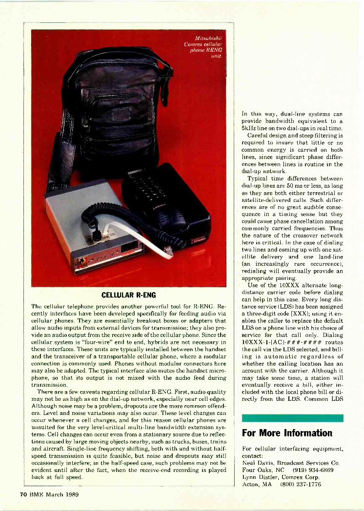
Mitsubishi,Comrex cellular
phone REND
CELLULAR R-ENG
The cellular telephone provides another powerful tool for R-ENG. Re-cently interfaces have been developed specifically for feeding audio viacellular phones. They are essentially breakout boxes or adapters thatallow audio inputs from external devices for transmission; they also pro-vide an audio output from the receive side of the cellular phone. Since thecellular system is "four -wire" end to end, hybrids are not necessary inthese interfaces. These units are typically installed between the handsetand the transceiver of a transportable cellular phone, where a modularconnection is commonly used. Phones without modular connectors heremay also be adapted. The typical interface also mutes the handset micro-phone, so that its output is not mixed with the audio feed duringtransmission.
There are a few caveats regarding cellular R-ENG. First, audio qualitymay not be as high as on the dial -up network, especially near cell edges.Although noise may be a problem, dropouts are the more common offend-ers. Level and noise variations may also occur. These level changes canoccur whenever a cell changes, and for this reason cellular phones areunsuited for the very level -critical multi -line bandwidth extension sys-tems. Cell changes can occur even from a stationary source due to reflec-tions caused by large moving objects nearby, such as trucks, buses, trainsand aircraft. Single -line frequency shifting, both with and without half -speed transmission is quite feasible, but noise and dropouts may stilloccasionally interfere; in the half -speed case, such problems may not beevident until after the fact, when the receive -end recording is playedback at full speed.
In this way, dual -line systems canprovide bandwidth equivalent to a5kHz line on two dial -ups in real time.
Careful design and steep filtering isrequired to insure that little or nocommon energy is carried on bothlines, since significant phase differ-ences between lines is routine in thedial -up network.
Typical time differences betweendial -up lines are 50 ms or less, as longas they are both either terrestrial orsatellite -delivered calls. Such differ-ences are of no great audible conse-quence in a timing sense but theycould cause phase cancellation amongcommonly carried frequencies. Thusthe nature of the crossover networkhere is critical. In the case of dialingtwo lines and coming up with one sat-ellite delivery and one land -line(an increasingly rare occurrence),redialing will eventually provide anappropriate pairing.
Use of the 10XXX alternate long-distance carrier code before dialingcan help in this case. Every long dis-tance service (LDS) has been assigneda three -digit code [XXX]; using it en-ables the caller to replace the defaultLDS on a phone line with his choice ofservice for that call only. Dialing10XXX-1-[AC]-###-#### routesthe call via the LDS selected, and bill-ing is automatic regardless ofwhether the calling location has anaccount with the carrier. Although itmay take some time, a station willeventually receive a bill, either in-cluded with the local phone bill or di-rectly from the LDS. Common LDS
111P9 VIP
For More Information
For cellular interfacing equipment,contact:Neal Davis, Broadcast Services Co.Four Oaks, NC (919) 934-6869Lynn Distler, Comrex Corp.Acton, MA (800) 237-1776
70 BME March 1989
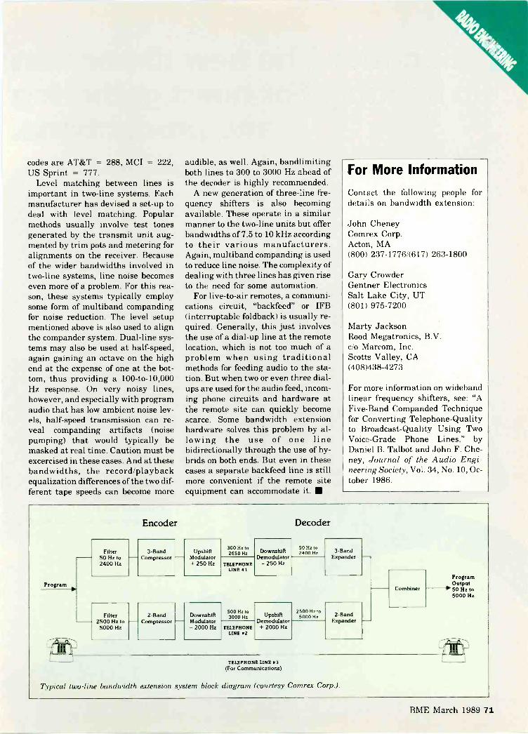
codes are AT&T = 288, MCI = 222,US Sprint = 777.
Level matching between lines isimportant in two-line systems. Eachmanufacturer has devised a set-up todeal with level matching. Popularmethods usually involve test tonesgenerated by the transmit unit aug-mented by trim pots and metering foralignments on the receiver. Becauseof the wider bandwidths involved intwo-line systems, line noise becomeseven more of a problem. For this rea-son, these systems typically employsome form of multiband compandingfor noise reduction. The level setupmentioned above is also used to alignthe compander system. Dual -line sys-tems may also be used at half -speed,again gaining an octave on the highend at the expense of one at the bot-tom, thus providing a 100 -to -10,000Hz response. On very noisy lines,however, and especially with programaudio that has low ambient noise lev-els, half -speed transmission can re-veal companding artifacts (noisepumping) that would typically bemasked at real time. Caution must beexcercised in these cases. And at thesebandwidths, the record/playbackequalization differences of the two dif-ferent tape speeds can become more
audible, as well. Again, bandlimitingboth lines to 300 to 3000 Hz ahead ofthe decoder is highly recommended.
A new generation of three -line fre-quency shifters is also becomingavailable. These operate in a similarmanner to the two-line units but offerbandwidths of 7.5 to 10 kHz accordingto their various manufacturers.Again, multiband companding is usedto reduce line noise. The complexity ofdealing with three lines has given riseto the need for some automation.
For live -to -air remotes, a communi-cations circuit, "backfeed" or IFB(interruptable foldback) is usually re-quired. Generally, this just involvesthe use of a dial -up line at the remotelocation, which is not too much of aproblem when using traditionalmethods for feeding audio to the sta-tion. But when two or even three dial -ups are used for the audio feed, incom-ing phone circuits and hardware atthe remote site can quickly becomescarce. Some bandwidth extensionhardware solves this problem by al-lowing the use of one linebidirectionally through the use of hy-brids on both ends. But even in thesecases a separate backfeed line is stillmore convenient if the remote siteequipment can accommodate it.
For More Information
Contact the following people fordetails on bandwidth extension:
John CheneyComrex Corp.Acton, MA(800) 237-1776/(617) 263-1800
Gary CrowderGentner ElectronicsSalt Lake City, UT(801) 975-7200
Marty JacksonRood Megatronics, B.V.c/o Marcom, Inc.Scotts Valley, CA(408)438-4273
For more information on widebandlinear frequency shifters, see: "AFive -Band Companded Techniquefor Converting Telephone -Qualityto Broadcast -Quality Using TwoVoice -Grade Phone Lines," byDaniel B. Talbot and John F. Che-ney, Journal of the Audio Engi-neering Society, Vol. 34, No. 10, Oc-tober 1986.
Program
Encoder Decoder
Filter 3 -Band Upshifl300 Hz to2650 Hz Downshift
50 Hz to2400 Hz 3 -Band
50 Hz to Compressor Modulator Demodulator ExpanderTELEPHONE2400 Hz + 250 Hz -250 Hz
LINE 01
Filter 2 -Band Downshift500 Hz to3000 Hz Upshift
2500 Hz to5000 Hz 2 -Band
2500 Hz to Compressor Modulator Demodulator ExpanderTELEPHONE5000 Hz - 2000 Hz + 2000 Hz
LINE 02
TELEPHONE LINE 03(For Communications)
Combiner
ProgramOutput
-1'50 Hz to5000 Hz
Typical two-line bandwidth extension system block diagram (courtesy Comrex Corp.).
BME March 1989 71

Sachtler. The new dimensionin lighting. For news gathering
and productions.Brighter, more equal distribution; lighter, more durable.
We will prove it to you atNAB '89.Open face technology with a focussingrange up to 1:6.Tungsten -halogen and flickerfree
daylight (HMI).
From 100 Watts up to 1.2 kw.For battery- and 110 AC -operation.
Switch on to Sachtler atNAB '89April 29th - May 2nd,or write for more information.
sachtlercorporation of america
55 North Main StreetFreeport, N.Y. 11520
Phone (516) 8 67-49 00
Telex 140107 sac frptFax (516) 6 23-68 44
California office:3316 West Victory Blvd.
Burbank, CA 91505Phone (818) 8 45-44 46
Circle 120 on Reader Service Card Page 63

Overall AC to RF efficiency of ahigh -power medium -wavebroadcast transmitter contrib-
utes significantly to-or detractsfrom-a radio station's profitability.Depending on a station's electricityrate and the power level of its trans-mitter, an efficiency increase of evena few percentage points can easilytrim thousands of dollars a year froma station's power bill.
Since 1967, pulse duration modula-tion (PDM) has become the standardtechnology in virtually all medium -wave transmitters. Typically a PDMtube -type transmitter has offered topoverall efficiency of about 65 percent.A PDM solid-state transmitter willgenerate about 73 per cent.
When combined with other designconsiderations, a new digital modula-tion technique developed by HarrisCorporation can result in typicaloverall AC to RF efficiency of 86 percent. Called Digital (Quantized) Am-plitude Modulation, the proprietarytechnology renders the transmissionsystem nearly transparent to inputaudio. The new transmitter designsalso greatly improve frequency re-sponse, harmonic and intermodula-tion distortion, squarewave responseas well as IQM.
The technology has been employedin the Harris DX series of 10, 25 and50 kW medium -wave transmitters.
Why do digital modulation andother design considerations so signifi-cantly increase overall efficiency? Wewill address this question by compar-ing a typical 50 kW PDM solid-statetransmitter with a 50 kW digitallymodulated model.
First, a number of factors deter-mine the efficiency of any device,which is defined as the output powerdivided by the input power: N =Po/Pin. The input power is equal to
DESIGNING EFFICIENTMEDIUM -WAVE
TRANSMITTERSRF efficiency is an important component of cost-
cffective station operation. Digitalmodulation techniques can improve operating
efficiency by one-third.
the output power plus losses in thedevice: [N = Po/(Po + Pd)] where Po= power out, Pd = power dissipatedin the device, and N = efficiency.
In a transmitter where power flowsthrough many devices in series, netefficiency is the product of each de-vice's efficiency, i.e.: N net = N1 x N2x N3...Nr. Devices normally found inan AM transmitter include:a. High -voltage power transformerb. Rectifiersc. Filter choked. Wiring to the modulator and RFamplifierse. Modulator, including modulationtransformer, or PDM filter compo-nents, PDM damper diodes, etc.f. RF power amplifiersg. Combiner (losses may be repeatedseveral times in some transmitters)h. Output filter/matching network.
Still other efficiency losses in a
BY NICHOLAS G. RICHARDSAND HILMER I. SWANSON
transmitter occur in the control cir-cuits, drivers and cooling system. Forexample, the efficiency of motors inthe cooling system can vary between60 percent and 90 percent dependingon whether they are a shaded pole sin-gle phase or high -efficiency threephase design.
In the case of a typical solid-statePDM transmitter (Figure 1), overallefficiency-the product of each de-vice's efficiency-is: (transformer N)(rectifier N) (filter choke N) (modula-tor N) (PA N) (first combiner N) (sec-ond combiner N) (output N) = N, or:(.95) (.98) (.99) (.94) (.92) (.98) (.98)(.98) = 75 per cent.
Additional power loss in the controlcircuits, drivers, cooling, etc. can beexpected to reduce overall efficiencyby about two percent, resulting in anet overall efficiency of approxi-mately 73 percent.
A modulator typically exhibits 94percent efficiency in 50 kW PDMtransmitters; a digital transmitter in-creases efficiency by eliminating the
BME March 1989 73

TYPICAL SOLID-STATE PDM TRANSMITTER EFFICIENCIES
HVXFMR
RECT FILTERCHOKE
MODU-LATOR
95% 98% 99% 94%
Figure 1: Typical solid-state PDMtransmitter efficiencies
HPAHPA -I-
PA
PA
C0
BNR
M
COMBN
92./o 98%
C
MB
N
R
- 98.,o
0UT
P
UT
98° o
modulator (see Figure 2).In brief, digital amplitude modula-
tion design replaces the modulatorwith a high-speed 12 -bit analog -to -digital (A/D) converter, a digitalmodulation encoder and a powerfuldigital -to -analog converter. This pro-duces an amplitude -modulated car-rier with a quantized envelope.
As used in radio broadcasting, anAM signal is a constant frequency rfsignal whose amplitude varies withthe audio input signal. The digitalmodulation process for this signaltakes place in four steps. First, themodulating audio signal is processedto provide an output signal that deter-mines both the carrier power leveland the modulation level of the trans-mitter. Second, the audio signal isconverted into a digital data streamsampling the audio at the carrier orsubmultiple of the rf carrier fre-quency. Third, the digital data fromthe converter is encoded to providedigital control signals to 42 of the 48
rf power amplifier modules needed,for example, for a 10 kW transmitter.Finally, the digital output of themodulation encoder switches individ-ual rf power amplifiers on and off.
Amplitude modulation is producedby switching on only the number of rfpower amplifiers needed to providethe transmitter rf power required atany instant. In a digitally modulatedtransmitter, the rf level at the trans-mitter output is changed by switchingon either a larger or smaller numberof rf power amplifiers, which are com-bined to produce total output. A fer-rite power splitter provides equal am-plitude, equal phase drive to thepower amplifiers.
In detail, the rf power amplifier sec-tion consists of 48 rf amplifier stagesfor a 10 kW transmitter. Since 48equal steps are not enough to repro-duce the modulation envelope accu-rately, binary weighted steps are usedto obtain the required resolution. The42 amplifiers controlled by the modu-
lation encoder are called "big steps"and each contributes an equal voltageto the combined output. The "binarysteps" (bits 7, 8, 9, 10, 11, 12) are con-trolled directly by the A/D converterand contribute 112, 1/4, 1/16, 1/32 and1/64 of the "big steps" respectively.The rf amplifiers are essentially con-stant voltage sources whose outputscombine in a multiturn primary, sin-gle secondary ferrite combiner to forman amplitude modulated carrier witha quantized envelope. This quantizedAM waveform is then filtered by abandpass network to remove un-wanted spectral components.
Note that the power output fromeach amplifier stage is not constant,but depends on the total number ofamplifiers or "steps" that are turnedon at any given time. The maximumpower output (for a given number of rfamplifiers) is limited by the currentrating of the rf transistors.
Each of the identical and inter-changeable RF power amplifierstages in the digitally modulated 50kW transmitter is a Class D switchingamplifier with four power MOSFETsin a bridge configuration (Figure 3).
Transistors Q1 and Q4 are driven180 -degrees out of phase to transis-tors Q2 and Q3. The amplifier outputis coupled to the output combiner viatransformer T3. During one-half ofthe RF cycle, transistors Q1 and Q4are driven into saturation (on) whileQ3 and Q4 are in cutoff (off), and dur-
OSCILLATOR
DX SERIES SIMPLIFIED BLOCK DIAGRAM
AUDIO INPUT
PREDRIVER
ANALOGINPUT
DRIVER
A/DCONVERTER
DRIVESPLITTER
MODULATIONENCODER
POWERD/A CCNV
POWERCOMBINER
OUTPUTNETWORK
Figure 2: Digitally modulated DX series simplified block diagram
74 BME March 1989

Ti
RF DRIVE
Q2
C R2
CR5
04
1 TURNSECONDARY
CR6
03
04
CR4
MODULATIONSIGNAL
01
HMODULATIONCONTROL Figure 3: RF power amplifier
T2
gRF DRIVE
0
ing the second half of the cycle, tran-sistors Q2 and Q3 are driven to satu-ration while Q1 and Q4 are in cutoff.The result is a squarewave peak -to -peak voltage of twice the bridge (DCsupply) voltage across the outputprimary.
In a Class D amplifier, there aretwo main components to loss of power:conduction loss and commutationloss. Conduction loss is equal toI(Square)Rds (Rds = drain to sourceresistance or MOSFET). It can beminimized by making the total Rds(on) as small as possible. This can beaccomplished by using a large num-ber of large transistors.
For a given power output, the trans-mitter with the largest amount of sili-con in the PA will have the lowestconduction loss. Total PA silicon areacan be obtained by multiplying thesilicon area in one PA transistor bythe total number of PA transistors,assuming similar Class D amplifiers,similar transistor construction andthe use of MOSFET transistors withratings between 100 and 500 volts.
Commutation (switching) losses in
most Class D amplifiers operating inthe broadcast band are usually aboutequal to conduction losses. Typicallycommutation loss is ordinarily aboutthree watts per transistor. The HarrisDX design uses an output networkcircuit which reduces commutationloss to about one watt per transistor.
Transistor efficiency in digitallymodulated designs measures about 96percent. As a result of efficient coolingand very little dissipation, the tran-sistor temperatures are close to ambi-ent, which results in little thermal cy-cling of the transistor. Combiner loss,outwork network loss and losses inthe "off' power amplifiers reduceoverall PA efficiency to 92 percent,however.
High voltage transformer and recti-fier designs also improve efficiency ina digital solid-state transmitter.
Rectifier efficiency is a function ofthe DC out and rectifier drop: N =(DC -2Vfm/DC) where Vfm is the di-ode voltage drop while it is conduct-ing. Efficiency will be very high if theDC voltage for the diode is high andthe voltage drop is low. A 50 kW digi-
tally modulated transmitter uses a230 VDC supply; oversized diodes areemployed to keep the diode voltagedrop low. Therefore efficiency of therectifiers in a 50 kW digitally modu-lated transmitter is approximately99 percent, where N = (230-2.2)/230.In a typical 50 kW PDM transmit-ter, rectifier efficiency is about 98percent.
Overall efficiency in a digitallymodulated 50 kW transmitter is:(transformer N) (rectifier N) (PA N) =N or: (.975) (.99) (.92) = 88.8 percent.
Power consumed by other circuitsincluding cooling, control and drivercause typical overall efficiency to beabout 86 percent.
Richards is project manager for the HarrisCorporation, Broadcast Division engineer-ing team which developed the DX digitallymodulated transmitter series. Swanson issenior scientist for Harris Corporation,Broadcast Division. He holds U.S. patentsfor the development of pulse durationmodulation, polyphase pulse durationmodulation and digital (quantized) ampli-tude modulation technologies.
BME March 1989 75

COMPUTE
Monitoring Point VectorAnalysis for Directional Antennas
By Ronald F. Balonis
n the world of the broadcast engineer theapplications and the uses for a PC canrange from the eclectic to the mundane.With programs stored in a computer,there's no need to memorize complex proce-dures and equations; these things a PC does
with ease.About half of the AM radio stations use direc-
tional antennas to either provide interferenceprotection to other stations or to provide the bestpossible coverage for themselves. This, of course,means that the ability to maintain a directionalantenna can be a required skill in a broadcastengineer's toolkit.
But the theory behind the design and the opera-tion of directional antennas is mathematicallycomplex and quite abstract. And the knowledgeproblem they pose is compounded because direc-tional antennas are custom designed for each par-ticular station ... no two are truly alike in allways, they come in all shapes and sizes.
While the initial design and adjustment isproperly the domain of expert consultant engi-neers, the maintenance and day-to-day operationof them seldom is. The day-to-day operation andmaintenance is the domain of the broadcastengineer.
This month's Compute application program is
called MPVECTOR.BAS. Itperforms vector analysis onthe monitor points of a di-rectional antenna. Vectoranalysis is the calculationof the resultant vectorfields produced by eachtower at monitoring points.The purpose of the analysisis to determine the effect that changing towerparameters has on the monitoring point fields. Itmakes for intelligent and systematic, rather thantrial and error, adjustment of directional broad-cast antennas.
Modeling the directional antenna withMPVECTOR.BAS lets you twist and tweak thecontrols to determine what control does what andby how much. This program's designed to en-hance your ability to maintain a directional ar-ray: to debug minor operational problems, to keepit adjusted to its licensed parameters, and to rec-ognize when it needs, and you need, the servicesof an "expert" consultant engineer to implementthe changes properly.
MPVECTOR.BAS is an interactive applicationprogram. First you input the data, the directionalantenna's parameters. Then you adjust towerphases and field ratios until a sequence of adjust-
ment is found, assuming there are nocomponent failures or system defects,that gives "in tolerance" parameter val-ues: loop currents, phases, and monitor-ing points.
The first part is for inputting data, ex-tends from line 100 to 625, and consistsof seven modules: The Number of Towersand the Field Ratio, Phase, Azimuthfrom true north, and the Spacing fromthe reference center of the array (a toweror a point) for each tower. Then theNumber of Monitoring Points and theirAzimuths from true north for vectoranalysis. Each data input module iscoded alike: Data input as a string vari-able and converted to a numeric valuethen tested for a valid value ... an errorcauses a top of the program restart andreentry of all the data.
+ Incremental DA Monitoring Point Vectors +
NUMBERTOWER
OF TOWERS (2# +> ++ 1 ++
to 6): ? 4
++ 2 ++ ++ 3 ++ ++ 4FIELD : 1.000 2.090 1.770 1.160PHASE : 0.0 -175.0 41.0 -109.0AZMTH 295.0 295.0 115.0 115.0SPACE 172.5 57.5 57.5 172.5
NUMBER OF MP (1 to 10): 7 5MP# +> + 1 + + 2 + + 3 + + 4 + + 5 +MP AZ: 36.8 193.2 265.7 295.0 324.33
VCTR%: +0.0 +0.0 +0.0 +0.0 +0.0 <REFVCTR%: +13.3 +13.3 +1.4 -0.2 +1.4 <FLDVCTR%: +0.0 +0.0 +0.0 +0.0 +0.0 <FLDVCTR%: +4.9 +4.9 +2.4 +1.6 +2.4 <PHVCTR%: +0.0 +0.0 +0.0 +0.0 +0.0 <PHVCTR%: -29.1 -29.1 +6.1 +3.5 +6.1 <FLDVCTR8: +0.0 +0.0 +0.0 +0.0 +0.0 <FLD
INCREMENT TOWER <1 to 4 > ?
Demo screen for MPVECTOR.BAS
++
FLD PH>1 +2% >
1 -2% >
1 +ldeg>1 -ldeg>2 +2% >
2 -2% >
76 BME March 1989

The second part does the actual vectoranalysis, it extends from lines 600 to 1030: Lines600 to 625 compute the reference vectors for theinput data fields and phases. The interactive partloops through lines 640 and 840: Lines 640 to 680display each MP vector as a percent change foreach monitoring point. Lines 700 to 840 promptfor the Tower, then Field or Phase to change andincrement: Field up or down by 2 percent andPhase up or down by 1 degree (Set in line 25,DF = .02 and DP =1.0). At the bottom of the pro-gram, lines 1000 to 1030 make up the subroutinethat calculates the directional antenna fields. Forhardcopy of a vector analysis sequence, use thePC's Print Screen key. You can do 10 calculationsbefore the results roll off the screen.
That's probably the easy part. Just follow theexample screen and sequentially enter the datafor the directional antenna to analyze. The hardpart is to effectively interpret and then to applythe analysis to the real -world directional an-tenna. To succeed at that, you've got to: 1) Docu-ment the system and it's components. 2) Thor-oughly checkout the antenna system. Be as sureas you can be that there are no faults or defects inthe system causing it not to behave as it once did.3) Make sure that the Monitoring Points are thereal ones and are "good" ones. 4) Be meticulous inrecording and logging the readings and the ad-justments that you make. 5) Make changes one ata time, to some extent they all interact with eachother. Finally, 6) know when you need, or itneeds, the services of an "expert consultantengineer."
For the theory and practice of directional an-tenna design, adjustment, and maintenance,BME has provided the forum for many of theexperts:
In the June 1978 issue, George W. Ing describesthe formulas for directional antennas in "ThePocket Calculator and the DA, Part 3," p. 86.
In the March 1980 issue, Ty H. Stites tells howto do "Vector Analysis of Directional Arrays," p.122. His method is to calculate them by hand;then plot the vector results on a sort of graphicalmap for each monitoring point. Somewhat likeMPVECTOR.BAS does, except thatMPVECTOR.BAS builds an on -screen tabulationof the vectors as percent change.
In the September 1983 issue, John H. Battisonprovides in "Facilities Design and EngineeringPart 10: Selecting and Installing an AM an-tenna," p. 75, an overview and guide on AMantennas.
And finally, in the January 1984 issue,Battison provides a one -page troubleshooting
checklist in the Great Idea Notebook: "Trouble-shooting Directional Antennas," p. 99. It's a veryuseful guide for debugging and adjusting any di-rectional antenna system.
Balonis is the chief engineer at WILK-AM, Wilkes Barre,PA.
495 '++ ENTER TRUE N. MP AZIMUTHS 0 to 360
500 PRINT 'MP AZ:":505 FOR I=1 TO MP:MP$="510 INPUT MPS:MP(I)=VAL(MP$)
515 IF MP(I)<0 OR MP(I)>360 THEN RUN 0
520 LOCATE 12,1+I*6:PRINT USING' #44.4';MP(I):
525 NEXT I:PRINT:PRINT:PRINT:PRINT595 '
600 FOR I=1 TO TWR:'+4+++ REF FIELDS & PHASES
605 DF(I)=1I:DP(I)=01610 NEXT I:'+++++ COMPUTE REF MP FIELDS615 FOR II=1 TO MP620 GOSUB 1000:E(II)=E625 NEXT II:FPWREF.:T$="FLD':D$="PH'635 '
640 '+++ DISPLAY THE it CHANGE IN MP VECTORS650 LOCATE CSRLIN-2,1:PRINT 'VCTRit:";655 FOR II=1 TO MP665 GOSUB 1000:E=100*(E-E(II))/E(II)670 IF E>99.9 THEN PRINT ' 100+ ';:GOTO 680
675 PRINT USING' +44.4";E;680 NEXT II:PRINT 0;FP$;* ";T$;" ';D$;DD$.>"690 '
695 '+++ INCREMENT A TOWER'S FIELD OR PHASE
700 PRINT SPACE$(79):PRINT:T$="705 LOCATE CSRLIN-1,1710 PRINT 'INCREMENT TOWER <1 to';TWR;'> : ';
715 INPUT T$:T=VAL(T$):IF T$=" THEN RUN 0720 IF T<1 OR T>TWR THEN 705725 FP$=":DD$=":0$="730 '
740 LOCATE CSRLIN-1,1:'++ BACKUP AND OVERWRITE PROMPT
750 PRINT 'TOWER .:T$:" <F>ield or <P>hase: ';
755 INPUT FP$760 IF FP$<>'F' AND FP$<>"P' THEN 740:++ NOT F OR P
765 IF FP$="F' THEN FP$='FLD':DDS='2%
770 IF FP$='P' THEN FP$=PH ':DD$="ldeg'
775 '
800 LOCATE CSRLIN-1,1.PRINT 'TOWER ";T$;' ';:p$="
805 PRINT FP$;' + UP or - DOWN: :
810 INPUT D$
815 IF D$<>'+' AND D$<>'-' THEN 770:++ NOT + OR -
820 IF D$='+' AND FP$=FLD' THEN DF(T)=DF(T)+DF
825 IF DS='-' AND FPWFLD' THEN DF(T)=DF(T)-DF
830 IF D$='+' AND FP$='PH ' THEN DP(T)=DP(T)+DP
835 IF D$='-' AND FP$='PH THEN DP(T)=DP(T)-DP
840 GOTO 650:+++ AND DISPLAY it CHANGE IN VECTORS
845 '
1000 '++++++ COMPUTE THE MP FIELD VECTOR
1005 E=0:X=0:Y=0:A0=MP(II)1010 FOR I=1 TO TWR
1015 SP=(PH(I)+DP(I))+SP(I)*COSHAZ(I)-A0)/RD)
1020 X=X+(FLD(I)*DF(I))*COS(SP/RD)
1025 Y=Y+(FLD(I)*DF(I))*SIN(SP/RD)
1030 NEXT I:E=SOR(X*X+Y*Y):RETURN:' PROGRAM END.
MPVECTOR.BAS, a vector calculation program.
BME March 1989 77

re11111111.11111111111.11.1.
riMMI111.111111111M111111
111,11111E11E1.11
It pays for itself...The Panasonic ME Cart
Panasonic

automatically.Machine. Available now.
AIR
Y.
OOOO
1000io C looMue..0..40n clop MD
114118=.11111 117M3o
InCiel: 33 m130 :1111131 MsIMOD:
1:101:1
anCianligE::: - m mm MI
DODD:9s a 000
,I,,,31:1.11M0001:INICI2CIENIn MBDODO;........I
. ociticio 08 ile
se MO
or
Now our most technologicallyadvanced cart machine is also oneof the most versatile. Presentingthe Panasonic WI cart machine. From 10 -second spots back to back,continuously, to two months of 24 -hourautomatic program airing. Uses 10-, 20-, 30-, 60- or 90 -minutecassettes in any desired mix. Capable of record and playback ofsingle or multiple events on the samecassette. Uses up to 5 standard MU studioVTR's plus 3 optional outside sources. Modular design-various configu-rations to sut user's needs and budget. Expandable-from 120 cassettes upto 3 rotary libraries that can hold over1,150 cassettes. User-friendly software and hardwaretailored to customer needs. Cost-effective operation and ease ofmaintenance and access. Backed by Panasonic MU 24 -hourservice support system.
PanasonicBroadcast Systems Company
Call our field offices now: Northeast: One Panasonic Way,Secaucus, NJ 07094; (201) 348-7671.Washington, D.C.; (703) 759-6900.Southeast: 1854 Shackleford Court,Suite 250, Norcross, GA 30093;(404) 925-6772.Midwest: 425 E. Algonquin Road,Arlington Heights, IL 60005;(312) 981-7325/(317) 852-3715.Southwest 4500 Amon Carter Blvd.,Fort Worth. TX 76155; (817) 685-1132.Western: 6550 Katella Avenue,Cypress, CA 90630; (714) 895-7209.Northwest: (408) 866-7974.
Circle 122 on Reader Service Card Page 63

SPECTRUMTHE REGULATORY ENVIRONMENT
How to Go DarkBy Harry Cole
t one time or another just aboutevery licensee needs to turn itsstation off-to "go dark," in thelanguage of the industry, fortechnical or occasionally finan-cial reasons. Since such in-stances are the exception ratherthan the rule, many broadcast-rs may not be completely famil-
iar with their obligations as far as the FCC isconcerned.
The Commission understands that we live in animperfect world where notwithstanding our bestefforts, things sometimes go awry. As a result, therule on going dark (Section 73.1740) anticipatesstations needing to cease operation for a shortperiod. In order not to add unnecessarily to theburden of such situations, the FCC permits a sta-tion to go off the air, or otherwise "limit" its oper-ation (presumably by operating with reducedpower, for instance), for up to thirty days withoutprior authorization from the FCC. That meansyou can just turn the station off if you feel like itfor up to 30 days. More realistically, if a tornadoblows your tower over, or if your transmitters ex-plodes, or if your studio burns down, yobOon'thave to worry about getting any kind of appAivalfrom the Commission if you are forced off -the airfor awhile.
There are two things you must keep in mind,however. First, you will be required to adherto the tower lighting requirements specifiedin your license at all times. The Commissionviews tower lighting as an extremely impor-tant safety consideration, and it expects alllicensees to take all necessary steps tomaintain compliance with thoserequirements.
Second, you must notify the Commis-sion that you have discontinued opera-tion within ten days of the discontinua-tion. This does not constitute a need toobtain approval-all you need to do isdrop the FCC a line to identify thestation and its community of licenseand advise the Commission thatthe station has discontinued
operation. You may include some details aboutthe underlying circumstances, if you wish, andadd when you expect to go back on the air.
The fact that you don't even have to notify theFCC until the tenth day is important because itcan be construed as permitting any station tocease operation for up to ten days without evennotifying the Commission. Thus if you blow atube which keeps your station dark for a daywhile a replacement is flown in, technically youwould not be required to advise the Commission.
If the station is going to be off the air for morethan 30 days, you will need to file an informalrequest for authority tokeep it off the air no laterthan the thirtieth day.Such an informal requestwould normally include adescription of the circum-stances forcing the discon-tinuation of service, andat least some projecteddate for the recommence -
men of operations. West ngly recommend that
u,nsult with yourconic counsel in preparing such a re-quesi.ekswith anything that gets filed with the
ission, it is absolutely essential that yourequ t be completely accurate and candid. Byorking with counsel, ideally you will be ableo craft a request which says what needs to besaid and which does not in and of itself createany additional risks for you.
The Commission will normally respond toa request for authority to discontinue opera-tion by sending the licensee a telegram inwhich such authority is granted through a
certain date (usually in the range of 90 to180 days from the date of the request).
Cole is partner inBechtel, Borsari, Cole& Paxson, a Washing-ton, DC -based law firm.
The telegram will also remind the li-censee that it will still have to complywith tower lighting requirements.
When you receive this authoriz-ing telegram, immediately enter thedate the authority to stay dark ex-
pires on your calendar. If
80 BME March 1989
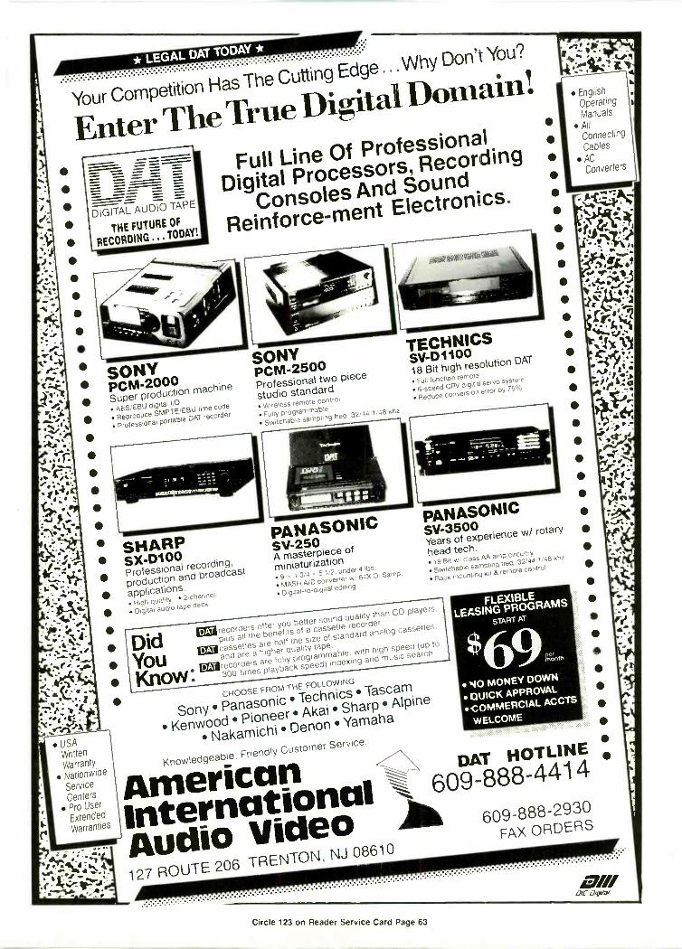
USAWrittenWarrantyNationwideServiceCenters
Pro User
ExtendedWarranties
. eye -.-71,414 Ir. e..._ -;.
.11. af 110.7.....re.
Your CompetitionHas The Cutting Edge ...Why Don't You?
EnterTheTrue DigitalDomain!
= == -== = =_ _
DIGITAL AUDIO TAPE
THE FUTUREOF
RECORDING ... TODAY!
SONYPCM-2000Super production AES/EBU
digital I/O
ReproduceSMPTE/EBU time code
Professionalportable DAT recorder
machine
Full Line Of Professional
Digital Processors, Recording
Consoles And Sound
Reinforce-mentElectronics.
410111111111111111WANNIMMIll
SHARPSX-D100Professional
recording,
productionand broadcast
applications. High quality 2 -channel
Digital audio tape deck
SONYPCM-2500Professional two piece
studio standard Wireless remote control
Fully programmable
Switchablesampling freq.
32/44.1/48 khz
PANASONICS V-250A masterpiece
of
miniaturization 9 1
3 4 5 1.2. under 4 lbs.
MASH A/D converterve 64X 0. Samp.
Digital -to -digital editing
TECHNICSSV-D110018 Bit high
resolution DAT
Full function remote
6 -speed CRV digital servo system
Reduceconversion error by 75%
PANASONICSV-3500Years of experience
w/ rotary
head tech. 18 Bit w/class AA amp circuitry
Switchablesampling freq.
32/44.1/48 khz
Rack mounting kit 8 remote control
DidYou
recorders offer you better sound qualitythan CD players
plus all thebenefits of a cassette recorder.
EN cassettesare half the size of standard
analog cassettes.
and are a higher quality tape.
Know:curecorders are fully programmable.
with highspeed (up to
300 times playback speed)indexing and music search
DAT
CHOOSE FROMTHE FOLLOWING
Sony Panasonic Technics Tascam
Kenwood Pioneer Akai Sharp Alpine
Nakamichi Denon Yamaha
Knowledgeable,Friendly Customer Service.
FLEXIBLELEASING PROGRAMS
START AT
'69mer
10 MONEY DOWN
CRACK APPROVAL
COMMERCIALACCTS
WELCOME
AmericanDAT HOTLINE
International609-888-4414
Audio Video A127 ROUTE 206 TRENTON,
NJ 08610
609-888-2930FAX ORDERS
.........................._,
Circle 123 on Reader Service Card Page 63
40:Liya--7.111.:
EnglishOperatingManuals
AllConnectingCables
ACConverters
7///0/c agra/

SPECTRUM
you're still not ready to go back on the air by thatdate, the note will remind you to file a request forextension of the authority to remain silent. Sucha request is also an informal matter which nor-mally provides the Commission with a progressreport and with an estimate of when the stationmight be expected to return to service. The FCCwill normally respond to an extension requestwith another telegram whichprovides a new date by whichthe station should resumeoperation.
When the station does re-sume operation, the licenseeis required to notify the Com-mission. This notification re-quirement applies with re-spect to any discontinuationof operation of which theCommission has been ad-vised, whether or not the dis-continuation lasted more than 30 days. In otherwords, if you have told the FCC that you're off theair, you have to tell them when you go back on theair. Your notification should specify the date youactually resumed operation. If you decide you aredefinitely not going to return the station to theair, you should also notify the Commission. Nor-mally you would send the FCC your instrument ofauthorization plus a letter indicating that you nolonger wish to operate the station and the licenseshould be cancelled.
What is the risk if you don't comply with therules? Theoretically, the willful and repeated vi-olation of any Commission rule can result in afine or forfeiture of up to $20,000. In real -lifeterms, the actual fine may be less than that. TwoCommission actions at the end of last year indi-cate the Commission's attention to such mattersisn't the most vigilant.
In the first case, the Commission ordered anAM licensee in Oregon in December 1988 to showcause why his license should not be revoked. TheCommission had learned in September 1986-more than two years before the show -cause or-der-that the station had been off the air sinceMarch 1986. Commission personnel inspected thestation site in November 1986 and found that thestation was indeed off the air, and further, thestation had been abandoned. Apparently not con-vinced that the licensee would not suddenly reap-pear, the FCC waited until July 1987 (by whichtime the station had been off the air for more than15 months) to send a letter to the station "seekinginformation as to the status of the station." Theletter was returned to the FCC stamped "Re -
82 BME March 1989
As withanything filed with the
Commission, it isessential your requestis completely accurate
and candid.
turned to Sender-Box Closed".Apparently the Commission still didn't believe
the station might really be dark for good. InMarch 1988-two years after it apparently firstwent dark and 16 months after an on -site inspec-tion revealed it abandoned-the Commission sentfield operation personnel back to the site to lookaround again. They found the station was still off
the air and so, nine monthslater, the Commission issueda show -cause order in an ap-parent effort finally to cancelthe license.
Ironically, the Commis-sion revoked the license of aWashington state AM li-cense the same week itadopted the show -cause or-der. The Washington stationhad been off the air sinceJanuary 1985. It first re-
quested authority to go dark for 90 days in Febru-ary 1985. Extensions of that authority were re-quested and granted through mid -August 1986.Apparently the licensee gave up sometimearound then, for no further extension requestswere forthcoming and a March 1987 inspection ofthe station site found it to be vacant. Still, inApril 1987 the Commission directed the licenseeto provide specific plans for the station's return tooperation. In response the licensee indicated thatit was looking for a buyer for the station. Elevenmonths later, with no assignment application onfile, the Commission ordered the licensee to showcause why its license should not be revoked. Thelicensee opted not to oppose revocation and fi-nally, in December 1988, the license was revoked.
From these two cases it is apparent that theCommission does not have a hair-trigger when itcomes to revoking licenses for failure to operate.Indeed, these two stations were off the air foryears before the Commission took any meaning-ful steps aimed at forcing the licensee itself totake steps. The FCC's willingness to let thingsslide in this area is probably attributable to avariety of factors, including the infrequency ofthis type of situation and a desire by the agencynot to be too hard-nosed when it comes to a li-censee who is having problems.
Nevertheless, you would probably be well-ad-vised to comply with the rules even if you don'tthink the Commission will penalize you if youdon't. As noted above, any decision you makeabout going dark, staying dark, or notifying theCommission etc., should be made only after con-sultation with your communications counsel.

SURPLUS EQUIPMENTFOR SALE
PURCHASED FOR OLYMPICSAVAILABLE FOR IMMEDIATE DELIVERY
VIDEODVEs, Small Production Switchers, Monitors, etc.
AUDIOAudio Consoles, Stereo Equipment, Recorders, Mics, etc.
RFMicrowave, 2 -way Radios, Wireless Mics, etc.
TESTWF Monitors, Scopes, Audio & Video Monitoring, etc.
TERMINALFrame Syncs, DAs, Clocks, etc.
For information contactNational Broadcasting Company30 Rockefeller PlazaNew York, NY 10112 Circle 124 on Reader Service Card Page 63
Surplus Olympic SalesTel: (212) 6642313Fax: (212) 664-7510

EQUIPMENT
Neumann New Mic Series....DesktopAudio with Sonic Solutions....ICI
Digital Paper....Sony InfraredCamera....And More New Products
Neumann Intros NewMicrophone Series
Microphones of the NeumannKM 100 series are modularcondenser mics with a small
diameter capsule. The active capsulewhich is only 1.5 inches long connectsto the output stage either directly orvia a thin cable up to 150 feet long.Hybrid, transforfnerless electronicsprovide 4 dB less self -noise, a 3 dBhigher output level, and a 12 dB widerdynamic range than the KM 83/84/85series. Dynamic range is 124 dB andRFI rejection is 30 to 40 dB. TheKM 140 cardioid is pricedat $600 and the KM 150 hyper-percardioid is $725.Reader Service#200
cordings with the help of a personalcomputer and applications software.The system provides all -digitalediting, mixing, EQ, dynamics andproject management functions forprofessional mastering. It allows theoperator to complete all the editing,equalizing, mixing, and CD prep func-tions with one system and engendersmore accurate editing, lessens thehassles of tape shuttling, and createsa finished master more quickly.
Reader Service#201
11
ICI LaunchesDigital Paper
Digital paper from ICIElectronics is a com-pletely new form of
Sonic Solutions DebutsNew Desktop Audio System
Using the Sonic System, record-ing engineers are able to pre-pare professional master re -
optical data storage medium. Highlyflexible, durable and low in cost, it of-fers the data density of optical disksand is readable by digital devices. Thenew medium can be slit into lengthsas tape, stamped into disks, insertedinto cassettes or cut into strips or
tags. Two drives, tape and disk, usingdigital paper as a medium have beenannounced and several more drivemanufacturers are working on imple-mentations of the new optical datastorage medium. A tape designed for atape drive being developed by CreoProducts of Vancouver will have a ca-pacity of one terabyte (one millionmegabytes).Reader Service #202
New Sony Camera WorksIn Infrared Light
Model DXC-3000IR uses CCDtechnology to capture highquality images in both infra-
red and normal light settings. Appli-cations range from investigatorywork to ENG. The remote controller,which includes both a control unit boxand filter drive unit, activates the fil-ter wheel, allowing the user to choosebetween the various light spectrummodes from a distance of up to 100meters. A five -meter cable is standardequipment. When the third filter isselected, green and blue signals areautomatically turned off and only thered channel is operational. The elec-tric charges generated in the red chipare processed by the circuits for green,including the image enhancer. Thiscontributes to the picture quality inthis mode.Reader Service #203
Lyon Lamb Presents VideoAnimation System
Lyon Lamb Video Animation Sys-tems has introduced the HR-VASystem, a new system de-
signed specifically for high -resolution84 BME March 1989

computer graphics animation andconversion to all video formats. Thesystem is comprised of the Lyon LambHRC high resolution converter, theMiniVAS animation controller, andall cabling and software for immedi-ate interface with high resolutioncomputer graphics workstations. TheHRC converts up to 1280 x 1024 60 Hznon -interlace RGB video to NTSCvideo or low resolution 525 -line RGBwith no loss of graphic information.Users of high resolution display de-vices are able to directly record or dis-play their images in standard videoformat. The HRC performs complexcompression operations and inter-faces with a wide range of high res-olution formats. The MiniVAS isdesigned to perform precise single -frame recording and frame grabbingfrom computer graphics systems to awide range of videotape recorders.The price is $17,500.Reader Service #204
N. Marshall Has GaAs FETI.L.A. Retrofit Amplifiers
N. Marshall and Associates intro-duces another member of theirmicrowave amplifier family.
The VR5964-2 and VR6471-2 amplifi-ers are a drop -in replacement for theGunn diode injection locked amplifier(I.L.A. , in video broadcast equipmentoperating at 5.9 to 7.1 GHz. Otherconfigurations are available includ-ing an amplifier with 40 dB gain at 2watts. Predicted power train M.T.B.F.is in excess of 25 years.Reader Service #205
Centro Unveils Two ENGVehicles
Centro Corporation has two newENG's. One is built around theFord E-350 Econoline Super
oitS BROADCAST SW1TCHER FOR $2995.
A
OPTIONS
SERIAL AND PARALLEL CONTROLMODULES FOR FULL EDITORCONTROL
RGB CHROMA KEYER/COLOR BARGEN. Model 6045
INTERCOM Model 6404 STEREO AUDIO FOLLOW Model 6800
SERIAL EDITOR INTERFACE
tS
AUTOMATIC WIPES AND MIXES (GPI TRIGGERABLE)
A0,E,
8
C
9. q. 141.4 111
PVWC
PVWA/B
STANDARD FEATURES
MASTER FADE TO BLACK, TWO KEYERS, MIX TO KEY OVER WIPE 12 PATTERNS BORDERED WIPES VARIABLE SOFT EDGES JOYSTICK POSITIONER
BLANKING PROCESSOR TEST MODE (FOR SYSTEM TIMING) GENILOCK SYNC GENERATOR 4 BLACK BURST OUTPUTS
CROSSPOINT LATCH CORP.
DOWNSTREAM KEYER FULL COLORIZER AUTOMATIC PREVIEW TWO FADER ARMS
SEND $15. FOR DEMO TAPE
95 PROGRESS STREET UNION, N.J. 07083 USACountry Code 1 (201) 688-1510 Telex 132850 FAX 688-8094
FINANCING AVAILABLE (SUBJECT TO CREDIT APPROVAL)
Circle 125 on Reader Service Card Page 63

1 kWFINALLY...
A FullySolid State1 kW UHF TV
Transmitter,*
NO TUBES!!!
VisitCOMARKAt NABBooth #5141To See TheLatestAdvancementsIn UHF TV
TransmitterTechnology.
S STANDARD
COMARKA 0: Thomson-CSF Company
Rt. 309 and Advance LaneColmar, PA 18915
(215) 822-0777 Fax (215) 822-9129 Telex 846075
Circle 126 on Reader Service Card Page 63
86 BME March 1989
EQUIPMENT
Van and the other around the GMCSuburban. The Ford features a 7.5 li-ter V8 engine, 347 cubic feet of cargovolume, a three -bay equipment rack,a 6.5 kW Onan generator, a 30- or 40 -foot Will -Burt mast, pan and tilt headwith remote control, work lights,HVAC, a DC to AC converter and rollaround seating. The GMC features a5.7 liter V8 engine, power steeringand brakes, two -bay equipment rack,work lights, 4.45 kW Onan generator,AC/DC distribution and monitoring,and 30- or 40 -foot Will -Burt mast.Reader Service #206
WSI Announces New RadarService
NOWrad From WSI Corp. fea-tures improved image qualityand advanced compositing. The
new system suppresses ground clutterfrom buildings and vegetation whichcan appear on the screen as precipita-tion, but does it in a new way thatdoes not suppress true weather sig-nals. Advanced compositing meansthat composite national and regionalradar images are composited simulta-neously. The system works with anyWSI-compatible graphics machineand can also be accessed at home on aPC. NOWrad users can specify morethan 800 regional images.Reader Service #207
ISS Engineering OffersSatellite Receiver
ISS Engineering has announcedthat it will soon release a new C -KU band IRD satellite receiver,
model GL5020, for the TV cable andbroadcast industries. The new re-ceiver will feature a videocypher mod-ule that can be removed from thefront panel by quick release latches.Tuning will be accomplished by eitherchannel or frequency. Audio outputswill be balanced. Provision will bemade for remote control.Reader Service #208
ACE Produces New RoutingSwitcher
,del VX164 is a 16x4 broad-cast quality video router inone rack unit featuring a local
control panel with flexible remotecontrol options. The new unit, avail-able in composite or component ver-sions, provides disturbance -free fieldor frame rate switching and DC res-toration. Multiple audio levels, joy-stick override and software config-ured serial panels are optional.Reader Service #209
ACE Markets ColorEncoders
ACE color encoders, models 204Nand 205N, convert RGB outputsfrom such sources as character
generators or paint systems into com-posite NTSC. The 204N features sixcomposite outputs, RGB or Y, R -Y, B-Y inputs and a test pattern generator,providing 32 test signals includingfull field and SMPTE color bars, redfield and pluge. The 205N has all thefeatures of the 204N plus Y, R -Y, B -Youtputs, enabling simultaneous feedsto component analog VTRs from

character generators. A TTL input op-tion is available for use with PC gen-erated pictures.Reader Service #210
MCI Intros UHF 'Hot'Switch
Micro Communications Inc. hasdesigned a small size "hot"switch and switchless com-
biner. The switchless combiner re-places the standard hybrid combineror switching combiner in dual trans-mitter systems. The hot switch allowsthe broadcaster to switch between ei-ther of two transmitter systems, simi-lar to a four -port transfer switch.Should one transmitter fail, the re-maining transmitter can be hotswitched to the output with no loss ofair time, says the manufacturer. Theunit operates with a push-button mo-mentary contact and can be remotelyoperated.Reader Service #211
Nady VHF Wireless SystemDesigned for ENG
TheNady 501 VR wireless system
is designed to provide studioquality sound anywhere, with a
compact size and light weight thatwork well in electronic news -gathering and electronic field produc-tion. The 501 VR operates on VHFhigh -band frequencies, with fivechannels between 170 and 216 MHzoffered standard, and other frequen-cies optional. Patented compandingcircuitry gives the 501 VR a dynamicrange of 120 dB and full frequency re-sponse of 25-20,000 Hz. The receiveris internally powered by a 9V battery,or externally powered from any 12Vto 35V power source. A headset out-put with volume control is designed tomake monitoring easy. Other fea-tures include a "rubber duck" an-tenna and removable belt clip. Trans-mitters are available in a choice ofminiature lavalier in a field -provenbodypack or hand-held model.Reader Service #212
GLOBAL SUPPORTdill FOR GLOBAL
COMMUNICATIONS
Ku -Band Special ApplicationTVVT AmplifierSystems
:
c.
Ito
Tested, tried and prover. by communications experts worldwide, MCLs Ku -BandSpecial Application T1Ar Amplifier Systems meet-and exceed-industryrequirements for reliable perormance under all conditions. Advanced technicaldes gn and superior mechanical layout allow MC_ equipment to operate effectivelyeven in the most extreme cases: inerference (EMI-radiation/RFI-susceptibility),electrical (power source), mechanical stress, environmental (temperature/humidity), general maintenance ano transportable applications.MCL offers a wide range of Ku -Band Spedal Application TWT Amplifier Systemsdesigned specifically fix the transportable sate'lite communications (video, voicearic data) market. For tnose who require hub -mounting or portable equipment,MCL has deliverable switch -mode Dower suppiies and a new range of specialconfiguration 1:1 redundant and VFC TVIT Amplifiers utilizing these powersupplies. Output powers range up 'o 500 Watts for a phase combined unit.
MCL is the leading manuacturer high -quality, competitively priced amplifiers,all of which are noted and proven for unsurpassed performance.
For '..echnical specifications anddetailed information about MCLs
,<u-Baid Special Application TWTAmplifier Systems, call or write
'141CL, and request your FREE copyof MCLs New Brochure #6010.
MCL, INC.501 S. Woodcreek Road3olingbrook, IL 60439312-759-9500 TWX 910-683-1899
Manufacturers of TWT and Kystron Amplifiers for Satellite Communications.24 -Hour Sales and Technical Support for Immediate Service Worldwide.
Circle 127 on Reader Service Card Page 63BME March 1989 87

Sony Adds Field -PortableU-Matic SP Recorder
Sony has introduced the VO-8800field -portable recorder with timecode capability. The new model
incorporates many of the features of
EQUIPMENT
its predecessor, the VO-6800, as wellas 330 lines of resolution and a signal-to-noise ratio of 46 dB. Additional fea-tures include Y/C interface capabilitythrough the 14 -pin camera cable,built-in rf modulator, lighted VU me-ter and C Type Dolby noise reductionfor audio signal-to-noise ratio of bet -
For AM, FM, SCAand TV modulation monitors.
WHEN ACCURACY COUNTS... COUNT ON...Call (215) 687-5550 or write for moreinformation on Belar AM, FM, Stereo, BELARSCA and TV monitors. -le CTRONIC LANCIPATORV, INC.Circle 128 on Reader Service Card Page 63 ASTER AVE AT DORSET DEVON, PA 19333
Small wonder we're usedby the giants.
ABC, NBC, KCOP, WPIX use our prime music cuts every day.Promos, spots, bumpers, PSA's, news, sports and weather-whatever you need, we've got it on one complete CD library.
With new releases added quarterly.Now you can sound like a giant with APM's Broadcast One!
Associated Production Music6255 Sunset Blvd., Suite 820 Hollywood, CA 90028(800) 543-4276 . (213) 461-3211 . FAX: (213) 461-9102
Circle 129 on Reader Service Card Page 63
ter than 72 dB. The VO-8800 also in-corporates SMPTE longitudinal tracktime code. The optional BKU-706time code generator plugs in to theunit and offers selectable free-run/record-run capability, regenera-tion to external time code and userbits entry.Reader Service #213
DSC Premieres Collage D-2Digital Compositor
Digital Services Corp.'s CollageD-2 digital compositor is de-signed for multi -channel corn -
positing of multi -layered effects andsophisticated program segments. Itfeatures a 12 -bit video path and cancomposite directly to D-2 tape ma-chines or disk recorders. The systemaccepts five video sources and threekey signals as external inputs. It com-posites three foregrounds over thebackground while controlling the pri-orities of two of the videos. Internalsources can be provided from optionalmatte generators, frame memories orDSC's DiSC digital disk system. Inputsources can be composited in a singlepass with manual or automatic dis-solves, fades, keys and cuts. Auto-matic dissolve durations and levelsare fully programmable.Reader Service #214
Telcom Compander CardWorks With Sony BVHSeries
Telcom c4 AC -27 audio compan-der card is designed to improvethe audio channels 1 and 2 of the
Type C 1 -inch video tape recorders inSony's BVH-2000/2500 series. It is areplacement card for the Sony AU -27board and plugs directly into the VTRslot requiring no modifications of theVTR. The card improves audio record-ing in dynamic range and crosstalkperformance, offering a quality com-parable to 16 -bit digital, according tothe manufacturer. The signal-to-noiseratio is referred to 250nWb/m, un-weighted. The card also corrects

frequency response errors with headbump effects, offering a frequency re-sponse of 50Hz-15kHz +/- 1 dB withNR off or on.Reader Service #215
Philips Digital OscilloscopeBrings Lab Power to Field
Anew portable 100-mHz digitalstorage oscilloscope from JohnFluke Mfg. Co., the Philips PM
3308, features an electroluminescentscreen, powerful mass storage mem-ory, and a wide range of arithmeticand analysis facilities. The PM 3308'sportability is enhanced by its clamshell construction and 14.5 -lb,.weight. Other features include ashoulder strap, battery -packed 180kBRAM disk with non-volatile memorythat can store up to 100 waveforms orsetup menus. DSO can display up to
four traces simultaneously. Verticalmeasurements include peak -to -peakand rms voltages, average DC leveland mean voltages across trace. Hori-zontal measurements include cursorto reference, cursor to trigger, rise -time, frequency, period and phase.GPIB and RS 232 interfaces are stan-dard. Delivery schedule is eightweeks; list price is $7500.Reader Service #216
Ampex Intros Pro AudioCassettes
IIntended for studio, dubs, clientcopies and other applications,Ampex Corp.'s 472 Studio Audio
Cassette is available in both Type INormal Bias and Type II High Biasconfigurations, and in 5-, 10-, 15-, 30-,45-, 60- and 90 -minute lengths.Reader Service #217
Programmable AudioSignal Generator/AnalyzerIntroduced
Sound Technology's 3100B gen-erator uses digitally controlledanalog oscillators to produce
sine and square wave signals in addi-tion to SMPTE IMD, tone -burst, andsine/step waveforms. Sine wavesrange from 1 Hz to 102.39 kHz, with0.0008 percent distortion, and squarewaves from 1 Hz to 50 kHz, with a risetime of less than 1µs, according to themanufacturer. Internal crystals in-sure frequency accuracy within 0.03percent for fixed frequency and se-lected frequency sweeps. The 3200Bautoranging audio analyzer measureslevels from below 4µv to 100 V in volts,dBM-referenced to 600 or 150Ohms-or watts (1 to 99 Ohm refer-ence), in greater than a 300 kHz band -
Ask for ourFREE CATALOG
of PRRECORDING
8LII%UPLICATING SUPPLIES
Blank -LoadedAUDIO CASSETTES
now from
STOCKin
CHICAGOand
L.A.
AGFA AMPEX3M Scotch
TDK maxellTAPE
Polyline Corp.1233 Rand Rd Des Plaines IL 60016
(312) 298.5300
The Telex LM -100 miniaturelapel mic system
The LM -100 is an omni-directional condenser mikesystem which includes the tinyLM -101 microphone and TelexPS -10 in -line phantom powersupply. This mike wasdesigned for day -in and day -out professional use under themost adverse conditions. Inenvironmental testing, theLM -130 performed perfectly inextremes such as below zerotemperatures, snowy televisioninterviews and on location inthe boiling heat of a desertHollywood movie set.
The Telex lapel mike has anon -glare black finish and issupplied with three styles ofmounting, clips. The mike hasa three foot cord terminated ina TA4F plug. This speciallydesigned cord is extra supple
and quiet to prevent irritatingclothing noise. A foam wind
screen is available as anaccessory for extra windy,outdoor use. For detailed
information writeTelex Communications, Inc.,9600 Aldrich Avenue South,
Minneapolis, Minnesota 55420.
'0 20 50 100 200 500 1k 2k 5k 10k 20k
Frequency in Hertz
Wide, flat, studio quality frequency response
TELEX®
Circle 130 on Reader Service Card Page 63
TELEX COMMUNICATIONS, INC.
Circle 131 on Reader Service Card Page 63

width. Three high-pass, four low-pass,or a weighting filter can be selected.Reader Service #218
AMX Shows Off 8 -LineRelay Controller
The AMX SX-8 + relay controlleris a trim line version of its stan-dard SX-16 + . The new unit fea-
tures eight relays instead of 16, andcommunicates with other AMX peri-pherals via the communications buss.Features include front panel controlsand rack mount capability.Reader Service #219
Vinten Has New Pedestal
11,inten's Vision pedestal offerspneumatic technology, tradi-tionally the preserve of heavy -
EQUIPMENT
weight camera systems, to users oflightweight equipment. Features in-clude a 16.5 inch on -shot columnmovement operable anywhere withina height range from 25 to 58 inches, afull 44 -lb. carrying capacity, a self -charging system for easy adjustmentof payload, detachable base with con-venient carrying handle and castoredwheels with individual brakes.Reader Service #220
RF Technology ReleasesMini MicrowaveTransmitter
RF Technology's RF-223B minia-ture portable microwave trans-mitter is available in any 250
MHz segment of the band 1.7-2.7 GHzwith rf power output switchable (1%watts at 2.0 GHz and 10/3 watts at 2.5GHz). Standard features include dual
high -quality audio channel withline/mic level switching, LPF videoinput, remote control capability,wideband (10 MHz), narrowbandvideo, baseband switching and 12VDC operation. Available options in-clude AC power supply, disc rod andparabolic antennas with gains up to25 dBi at 2.0 GHz. The unit measures4.5 x 5.0 x 7.0 inches and weighsabout eight lbs.Reader Service #221
Interface Unit ControlsChyrons
Zaxcom Video's DP800 Data Par-rot is a GPI pulse to RS422/232interface unit. When a GPI pulse
is received by the Parrot, a user -pro-grammable data string is generated,simulating keyboard keystrokes.Applications include control of older
The wireless system thatwill never leave you speechless.
ili11111111111111i
If thi ha ev r hap ned t yo , you weren't using a SonyVHF wireless microphone.
Rather than a mere one, two or ten channels, the Sonywireless system gives you up to 168. So no matter where youare, no matter how cluttered the airwaves, the signal willcome through loud and clear. And with so many open chan-nels to choose from, multi -microphone setups are a snap.
For added insurance, Sony wireless arms you with truespace diversity reception. 1Win tuners constantly compare
incoming signals for the strongest, clearestsignal. Sparing you the echoes, dead spots andother horrors that plague lesser systems.
So, if you're looking for a wireless system youcan have faith in-any time, any place-contact yourSony Professional Audio representative. Or callSony at 800 -635 -SONY. SONY;
Professional Audio
Sony Communications Products Company, Professional Audio Division, 1600 Queen Anne Rd., Teaneck, NJ 07666. 1988 Sony Corporation of America. Sony is a registered trademark of Sony Corporation.
Circle 132 on Reader Service Card Page 63
90 BME March 1989

Chyrons directly from an editor's GPIoutput. The Parrot contains eightnon-volatile memory buffers, each ofwhich may be up to 14 characters inlength.Reader Service #222
Tec Pro Intros DistributionAmp
Iris new audio distribution am-plifier from Tec Pro Technology,Inc. features a frequency re-
sponse of +/- .1 dB 10 Hz -22 kHz, S/N95 dB, distortion 1 kHz <.007, separa-tion >90 DB, input -10 to + 10 dBm,output + 20 dBm. It also featuresLED peak indicators, mono/stereobridge switch, headphone monitorjacks, two unbalanced high-level out-puts via RCA jacks, individual outputcontrols, and RF input protection.Reader Service #223
Master Control Switcher IsEntry -Level Unit
Utah Scientific's MC -501C mas-ter control switcher is an entry-level unit offering many of the
features of the company's MC -500family of switchers. The unit has 20source selectors which can be associ-ated with video only or video plus au-dio; there is an additional audio -only
function machine control system withindividual pre -roll times for eachsource machine.Reader Service #224
PCO Announces FiberOptic Data Link
PCO, a subsidiary of CorningGlass Works, has announcedthe EDL-1300 series of fiber op -
Take Me Out To The Ball GameOr just tare me out. The STLX extender/
console puts you on the air when you're onthe road.
With the STLX, when you leave the studioyou don't leave studio quality behind. Thebuilt-in Comrex Dual -Line frequencyextender with multiband noise reduction willdeliver full program audio on two dial tele-phone lines-anywhere in the world.
And everything you need is all together inone professional package. This is a studio -quality console that's rugged enough for theroad, with a four -input mixer (Penny & Giles°faders are standard), complete telephoneinterface, full monitor system with *back,AGC, PA feed and more. An optionalWerypack is available as well as a custom shippingcase that will stand up to the airlines.
For more information on how Comrex canhelp your road games, call or write ComrexCorporation, 65 Nonset Path, Acton, MA 01720(508) 263-1800. TWX 710-347-1049. FAX(508) 635-0401. 1-800-237-1776.
01/11a/11 MI ®ivirinriamma&Circle 133 on Reader Service Card Page 63

*NEWAVCOM PSA-37D PORTABLE SPECTRUM ANALYZER
AVCOM INTRODUCES THE NEW PSA-37D PORTABLE SPECTRUM ANALYZER WITH DIGITALFREQUENCY READOUT. AVCOM'S NEW PSA-37D Portable Spectrum Analyzer has a 4 digit frontpanel frequency readout and is controlled by a rotary frequency adjustment control. Frequencyranges that the PSA-37D cover are 0 to 500 MHz, 500 to 1000 MHz, 950 to 1450 MHz. 1250 to 1750MHz and 3.7 to 4.2 GHz. The PSA-37D Portable Spectrum Analyzer is lightweight, portable, batteryoperated, ideal for field test situations. A built-in DC block with a .18 VDC powers LNAs and BDCswith the flip of a switch. All other performance characteristics and features are the same as thePSA-35A which has become an industry standard for satellite communications work. $2475
AVCOM INTRODUCES A FULLY AGILE SINGLE CHANNEL PER CARRIER DEMODULATOR,THE SCPC-3000E, FOR VERSATILE AND ECONOMICAL RECEPTION OF SCPC SIGNALS. TheSCPC-3000E Demodulator features a high-performance synthesized 50-90 MHz tuning module formaximum system versatility. Frequencies are tunable in 800 steps of 50 KHz each. Standardexpansions are 31 and 2:1, other expander formats are available. Deemphasis is switchable between0. 25. 50. and 75 micro -seconds, Selectable low-pass 15. 7.5. and 5 KHz audio filters are standard.AVCOM can customize the SCPC-3000E Agile SCPC Demodulator to suit specific receiver needs.contact AVCOM with your requirements. 51378
AVCOM 500 SOUTHLAKE BOULEVARD, RICHMOND, VA 23236Tel. (904) 794-2500 FAX (804) 794-8284 Telex 701-545
Circle 134 on Reader Service Card Page 63
Misted®
FREECATALOG
Video Furniture SystemsBig, full color catalog includes complete
descriptions, pricing and ordering information on:
Editing Consoles Video Consoles Equipment Cabinets Micro Computer Stations
Tape & Film Storage Systems
Winsted Systems ... the Perfect Matchfor all professional Video Equipment
THE WINSTED CORPORATION10901 Hampshire Ave. So. Minneapolis, MN 55438
TELEX:510-601-0887
Call fohoneToll Freer
your nearest dealer(800) 447-2257P
FAX: 612-944-1546
EQUIPMENT
tic data links. The seriesconsists of two data linkmodules, the EDL-1300-TXtransmitter and the EDL-1300-RX receiver. Ideal forfirst-time users and for up-grading a coaxial or shortwavelength fiber system forgreater link distance andhigher speed, these moder-ate -speed data link mod-ules transmit serial TTLdata over multimode opti-cal fiber for link distancesin excess of two kilometersand at data rates up to 50Mbps. The benefits of highperformance and 1300-nanometer wavelength op-tical communication arecombined with the designfeatures of 16 -pin DIPhousing. Price per set inunit quantities is $320.Reader Service #225
EEV PremieresTraveling WaveTube Amplifier
EEV's latest travelingwave tube amplifierfor Ku -band SNG
applications, type N4290,provides 270 W rf output atfrom 14.0 to 14.5 GHz in anextremely compact (7 x 19 x24) and lightweight (66lbs.) package. Intended foruse in ground mobile envi-ronments, the N4290 is de-signed to be compatiblewith most environmentalconditions experienced bySNG terminals. Its operat-ing temperature range isfrom -20 to + 122 degrees F.Optional items include aweatherproof transportcase, remote control andmonitoring (including therf output power), computerinterface and phase com-biner for combining theoutputs of two N4290s.Reader Service #226
Comtech PremieresL -Band Antenna
Comtech Antenna, incooperation withSeavey Engineering,
has introduced anINMARSAT antenna sys-tem. The Model AS33-15C/U is a 33 -inch diametercollapsible antenna de-signed for L -Bandtransmit/receive applica-tions. The antenna was de-signed for airline transportand weighs just 40 pounds.It complies fully withINMARSAT SES sideloberequirements and can bedeployed by one man in ap-proximately one minute,says the company.Reader Service #227
Alta ImprovesCeleris Y/CFormat Converter
lta Group has added aluma-chroma delayorrection circuit to
their Celeris U-matic/S-VHS format converter. Thenew circuit provides bothdigital vertical and hori-zontal correction and solvesthe chroma delay problemcritical to multi -generationcopying. Celeris convertsprogramming from the U-matic and U-matic-SP for-mats to S -VHS or from thenew S -VHS format back toU-matic dub mode. Price is$1850.Reader Service #228
A.F. AssociatesPresents NewStandards Converter
International Signal In-terface System (ISIS) is asignal converter from
Circle 135 on Reader Service Card Page 63

A.F. Associates that is designed to fillthe gap between the Applied VideoSystems 6500 and ADAC. Intendedfor the mid -range post -productionmarket and the high -end corporatemarket, the new converter featuressmoothness of motion. ISIS is a three -field unit (expandable to four) offer-ing two-line interpolation. ReaderService #229
FOR -A Improves Time BaseCorrector
ir-A Corp. of America has an-nounced that its FA -740 paralleleffects time base corrector for
A/B roll editing applications can nowbe used with S -VHS systems. Operat-ing as two independent time base cor-rectors, the FA -740S integrates both1/2 -inch and 3/4 -inch U-matic VTRswith or without external sync inputsince its full frame correction range al-lows processing of non -synchronousVTRs. This also permits the combiningof a playback VTR with a studio cam-era in editing applications. Used incombination with the For -A EC -740editing controller and AS -740 audioswitcher, the FA -740S system has thecapacity to handle sophisticated A/Broll editing for Super -VHS systems.Reader Service #230
Hewlett-Packard Premieres6.5-GHz Portable SpectrumAnalyzer
Model HP 8561A from theHewlett-Packard Co. extendsthe performance of its porta-
ble spectrum -analyzer series. By us-ing solid-state electronic switching,the HP 8561A spectrum analyzer be-comes the first rf analyzer to providecontinuous sweep capability from 1kHz to 6.5 GHz. Tracking preselectionextends from 2.75 to 6.5 GHz, elimi-nating concerns about multiple re-sponses or images when analyzinghigh -frequency signals. Mean -time -between -failure rate is 10 years(based on 2000 hours per year).Reader Service #231
A Good Reason To Call RTS
When You're In The Business
Of Recordin On Tape.
Our Model 927 Programmable Reference Tone Generator adds a newdimension to tape recoding qmlity assurance.
Operating in a stem mode, it is user programmable with discrete tones,pink noise, noise reduction tones, phas check, stereo I.D. and more.
We think the 927 can mprcve your audio business. Please call or writefor descriptive literature.
PROFESSIONAL INTERCOMMUNICATIOI,S PRCFESSIONAL AUDIO PRODUCTS RTS SYSTEMS114CORP OR t ED
1100 Wxst Chestnut Street BUrbanc. California 01506 Telep lone 818 840 7119 Telex 194855 Telefax 818 842 4921

3 -Way Lounger
One of these revolutiothe world loolcs atilt%
BTS did not invent the three-way lounge chair. Barcalounge?did.But you'd be surprised at how many of the most revolutionary ideas in the history of video
did come from BTS. In fact, because we look at things differently, the whole world looks at thingsdifferently.
We introduced the first CCD film scanner, for instance. The first Plumbicon camera tube.The first software -based character generator. The B format for videotape recording. The modularrouting switcher. And of course, the first 3-D computer animation system, for which we won oneof our three Emmies.
BTS has been a technological innovator in the video industry for six decades. Our cameras,

3-D Computer Animation
switchers, videotape recorders and graphics equipment are among the best -engineered, highestquality and most reliable in the world. Our work in High Definition and CCD products is pacingan industry which faces the most sweeping technological advances since its beginning.
And we're as dedicated to better product service and support as we are to better products.So although BTS may not yet be a household word, here's a word to
the wise. In the years ahead, BTS will continue to be more forward thinking,more responsive and more innovative in our approach to video technologythan anyone else. The name behind
Including Barcalounger. what's ahead.BTS is Broadcast Television Systems, a joint company of Bosch and Philips. For more information, please call 1-800-562-1136 or write BTS. P.O. Box 30816. Salt Lake City. UT 84130-0816.
Circle 137 on Reader Service Card Page 63
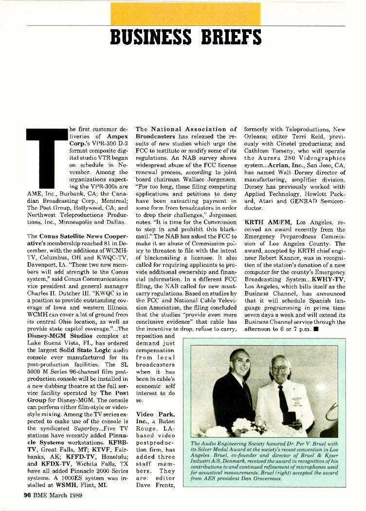
BUSINESS BRIEFS
Erihe first customer de-liveries of AmpexCorp.'s VPR-300 D-2format composite dig-ital studio VTR beganon schedule in No-vember. Among theorganizations expect-ing the VPR-300s are
AME, Inc., Burbank, CA; the Cana-dian Broadcasting Corp., Montreal;The Post Group, Hollywood, CA; andNorthwest Teleproductions Produc-tions, Inc., Minneapolis and Dallas.
The Conus Satellite News Cooper-ative's membership reached 81 in De-cember, with the additions of WCMH-TV, Columbus, OH and KWQC-TV,Davenport, IA. "These two new mem-bers will add strength to the Conussystem," said Conus Communicationsvice president and general managerCharles H. Dutcher III. "KWQC is ina position to provide outstanding cov-erage of Iowa and western Illinois.WCMH can cover a lot of ground fromits central Ohio location, as well asprovide state capitol coverage."...TheDisney -MGM Studios complex atLake Buena Vista, FL, has orderedthe largest Solid State Logic audioconsole ever manufactured for itspost -production facilities. The SL5000 M Series 96 -channel film post -production console will be installed ina new dubbing theatre at the full ser-vice facility operated by The PostGroup for Disney -MGM. The consolecan perform either film -style or video -style mixing. Among the TV series ex-pected to make use of the console isthe syndicated Superboy...Five TVstations have recently added Pinna-cle Systems workstations. KFBB-TV, Great Falls, MT; KTVF, Fair-banks, AK; KFFD-TV, Honolulu;and KFDX-TV, Wichita Falls, TXhave all added Pinnacle 2000 Seriessystems. A 1000ES system was in-stalled at WSMH, Flint, MI.
The National Association ofBroadcasters has released the re-sults of new studies which urge theFCC to institute or modify some of itsregulations. An NAB survey showswidespread abuse of the FCC licenserenewal process, according to jointboard chairman Wallace Jorgensen."For too long, those filing competingapplications and petitions to denyhave been extracting payment insome form from broadcasters in orderto drop their challenges," Jorgensennotes. "It is time for the Commissionto step in and prohibit this black-mail." The NAB has asked the FCC tomake it an abuse of Commission pol-icy to threaten to file with the intentof blackmailing a licensee. It alsocalled for requiring applicants to pro-vide additional ownership and finan-cial information. In a different FCCfiling, the NAB called for new must -carry regulations. Based on studies bythe FCC and National Cable Televi-sion Association, the filing concludedthat the studies "provide even moreconclusive evidence" that cable hasthe incentive to drop, refuse to carry,reposition anddemand justcompensationfrom localbroadcasterswhen it hasbeen in cable'seconomic selfinterest to doso.
Video Park,Inc., a BatonRouge, LA -based videopostproduc-tion firm, hasadded threestaff mem-bers. Theyare: editorDave Frentz,
formerly with Teleproductions, NewOrleans; editor Terri Reid, previ-ously with Cinetel productions; andCathleen Tomeny, who will operatethe Aurora 280 Videographicssystem...Acrian, Inc., San Jose, CA,has named Walt Dorsey director ofmanufacturing, amplifier division.Dorsey has previously worked withApplied Technology, Hewlett Pack-ard, Atari and GENRAD Semicon-ductor.
KRTH AM/FM, Los Angeles, re-ceived an award recently from theEmergency Preparedness Commis-sion of Los Angeles County. Theaward, accepted by KRTH chief engi-neer Robert Kanner, was in recogni-tion of the station's donation of a newcomputer for the county's EmergencyBroadcasting System...KWHY-TV,Los Angeles, which bills itself as theBusiness Channel, has announcedthat it will schedule Spanish lan-guage programming in prime timeseven days a week and will extend itsBusiness Channel service through theafternoon to 6 or 7 p.m.
The Audio Engineering Society honored Dr. Per V. Bruel withits Silver Medal Award at the society's recent convention in LosAngeles. Bruel, co-founder and director of Bruel & KjaerIndustri AIS, Denmark, received the award in recognition of hiscontributions to and continued refinement of microphones usedfor acoustical measurements. Bruel ( right) accepted the awardfrom AES president Dan Gravereaux.
96 BME March 1989

ADVERTISERS INDEX
Manufacturer Page Circle Manufacturer Page Circle Manufacturer Page CircleNo. No. No. No. No. No.
American International Harrison Systems 33 114 Sony Broadcast ProductsA/V 81 123 Inc. 12-13
Ampex AVSD 35 38 115 Leader Instruments 14 106,107 Sony Broadcast Products,Associated Production Leitch Video Ltd. 18 109 Inc. 28-29
Music 88 129 Sony Broadcast Products,Avcom of Virginia 92 134 MCL, Inc. 87 127 Inc. 54-55
Midwest Corporation 6 103 Sony Pro Audio 90 132Belar Electronics 88 128 Sony Tape Sales Co 10 105Broadcast Electronics, Inc. 8 104 NBC 83 124 Sony Pro -Video 4-5 102BTS Inc. 94-95 137 Standard Communications
Panasonic Broadcast Corp 53 118Cablewave Systems 3 101 Systems Co. 78-79 122 Switchcraft 24 112Canon USA, Inc. 58-59 119 Panasonic Industrial Co. 20 110
Comark Communications 86 126 Panasonic Industrial Co. 46-47 117 Telex Communications .... 89 131Comrex Corporation 91 133 Polyline Corp. 89 130Crosspoint Latch 85 125 Utah Scientific 16 108
R -Scan 22 111
Dolby Laboratories, Inc. .. 45 116 RI'S Systems 93 136 Ward -Beck Systems, Ltd. .. Coy. IVWheatstone Corp Coy. II 100
The Grass Valley Group ... Coy. III 138 Sachtler Corp. of Winsted Corporation 92 135The Grass Valley Group . . . 26 113 America 72 120
SALES OFFICES295 Madison Avenue, New York, NY 10017 Telex: 64-4001
Eastern States Western States Europe/United Kingdom Japai/Far East295 Madison Avenue 21757 Devonshire Street 33A Station Road 5-24 SanbanchoNew York, New York 10017 Suite 3 North Harrow Chiyoda-ku, Tokyo, 102 Japan212-685-5320 Chatsworth, CA 91311 Middlesex HA2 7SU England (81-3) 234-2161 Telex: J28208Telex: 64-4001 818-998-5154 (01) 427-9000 Fax: (81-3)234-1143William P. Dey Denice Nichols Telex: 21289 Takashi Kasai Sholehl Maruyama
Ric Bessford
CHIEF ENGINEER
State-of-the-art Southwest inder-indent in top 10market seeks dynamic, progressive leader withmotivational and communicative skills. Needs com-plete knowledge of broadcast operations, satellitingand transmission. Ability to work with others andmanagement.
Send resume to Phil Crow P.O. Box 2595 Fort Worth,Texas 76113.
TELECOMMUNICATIONS MANAGER
Major midtown Manhattan office building seeksknowledgeable "hands-on" supervisor of multi -type telecommunications transmission center.Engineering, leasing/licensing background essen-tial. Ability to coordinate with broadcasters, build-ing's operational staff and technical consultantsrequired. Submit detailed resume, salary history andrequirements to: BME Magazine, 295 Madison Ave.,NY, NY 10017.
CLASSIFIED
The Christian Science Monitor's Radio OperationsDepartment has immediate openings for on -air/production and Master Control engineers. Respon-sibilities include story and show assembly, on -airdrive shifts, and satellite reception and transmission.Knowledge of Pacific recorders, A MX and BMX con-soles are a plus. Our domestic programming in-cludes Monitoradio Daily edition and Weekendedition. Our international, 500Kw shortwaveprogramming includes the World Service of TheChristian Science Monitor, and the Herald of Chris-tian Science. If you're interested in applying, pleasecontact The First Church of Christ, Scientist, Person-nel Department, A130, 175 Huntington Ave., Boston,MA 02115, or call 1-800-225-7090, Ext. 3860. We arean Equal Opportunity Employer.
TV TECH
Located 12 miles outside Philadelphia, VillanovaUniversity, a private co-educational institution withan enrollment of 12,000 is seeking a TV TECH-NICIAN.
Trouble -shoot and fix systems comprised ofcameras, VCR's, generators, processors and moni-tors; perform video production and student training.
Associate's in related area, Bachelor's preferred;must have technical exp. in use/repair of mediaequipment or eng ineering background; may requireevening/weekend work.
SEARCH -TVVILLA NOVA UNIVERSITY
PERSONNEL OFFICE-STONE HALL816 LANCASTER AVENUE
VILL ANOVA, PA 19085
AA/EOE/M-F

CURRENTSA GUEST EDITORIAL
State -of -the -Month: The Challenge ofStaying Current
By Don Lockett
roadcast managers and broad-cast engineers are constantlyfaced with the challenge ofcompetition. Being competitiveis akin to being profitable forcommercial broadcasters andto being underwritten for non-commercial broadcasters. Theprogramming as well as the
technology that we use to deliver the on -air prod-uct are the principle tools of the trade. Therefore,knowledge and application of the latest broadcasttechnology becomes a basic housekeeping obliga-tion for today's broadcaster.
Integrating the best technology involves in-formation gathering and training. Broadcastersmust be able to install and maintain the new bellsand whistles and deal with compatibilities of oldand new equipment over the long term. Unless weare the recipients of large annual budgets or com-plete rebuild financing, this integration of newer,existing, and older broadcast technology becomesan artful dance. The broadcast engineer mustbe able to understand the theory of operation ofnew technology, assess its advantages and disad-vantages, and negotiatean equitable purchase.
Then comes the work-place implementationwhich often involves im-mediate training ex-penses for maintenanceand operational person-nel. Having the latest is ofno advantage if it cannotbe fully utilized. In mostcases, today's union con-tracts place stringent re-quirements on employersto provide training for op-erational personnel whennew technology is intro -
Don Lockett is the director ofengineering and operations,Program Division for Na-tional Public Radio.
duced. The training cost adds an extra, often sub-stantial, cost to the acquisition and should be con-sidered when negotiating.
The manufacturers of equipment have nothelped matters any with their rapid fire introduc-tion of new products. However, manufacturersare really not to blame because they too are thevictims of the infamous state-of-the-art factor. Aheightened competition level has been caused bythe proliferation of industry trade shows. Eachmanufacturer is advantaged by the introductionof state-of-the-art products when its target audi-ence gathers for technical expositions (i.e.,SMPTE, AES, and NAB). Consequently, we findourselves grappling with the introduction of im-proved digital video formats, more incompatibledigital audio workstations, and whatever NAB'89 will bring forth. The pressure of competitionat the major trade shows has taken on the sem-blance of the new car industry. While NAB's An-nual Convention originally established the newcar year, the frequency and importance of theother broadcast/audio/video events has created aquarterly, if not monthly, barrage of new im-proved widgets.
Staying current techno-logically also requiresstaying current profes-sionally. Continuing edu-cation is the only pre-ventative for professionalobsolescence and careerdisasters. Since broadcastengineering as a profes-sion pis being challengedon several fronts, it is upto today's broadcast engi-neer to establish, main-tain and prognosticate thelegitimacy of the vocation.The broadcast industrymust give urgent and im-mediate attention to thecontinuity of a broadcastengineering pipeline if com-petent expertise is to beavailable in the future.
98 BME March 1989

Kadenza DPP -1
The rapidly evolving GrassValley Group® range of digitalequipment is spearheaded byKadenza. TM Compatible withanalog. Ready for digital.
Kadenza is the perfectinvestment for your productionrequirements. For now. And forthe future.
Kadenza is the first real-time multi -layer compositing
device for post productio aprofessionals. Its infinitelyflexible modular design allows itto be configured to meet thechanging needs of your facility.
It reflects the Grass ValleyGroup philosophy of makingthe analog to digital transition asmooth one.
When the all -digital studiois commonplace, there will be
...in the smoothtransition
one common standard everyonecan rely on.
Trust GVG for that, it'shere now . . . and it's calledKadenza.
Contact your Grass Valley Groupdistributor for the full story.
Grass Valley Group R
A TEKTRONIX COMPANY
_tVG\_ THE GRASS VALLEY GROUP INC.P.O. Box 1114, Grass Valley, CA 95945 USATelephone (916) 478-3000, TRT: 160432Circle 138 on Reader Service Card Page 63
OFFICES: New York (201) 845-7988. District of Columbia 3011622-6313; Atlanta , 404: 493-1255; Chicago (2191264-0931;Minneapolis 1612) 483-2594; Dallas/For Werth (817)483-7447; Los Angeles ,818) 999-2303: San Francisco (415) 968-6680;GVG International Ltd. (UK) +44962-643939; Grass Valley Group Asia k HK) +852-3-7396632

.1111111.11111
Nobodydoes- it better!
Ward -Beck's all -new D8212 Audio DistributionSystem is totally Iransparent! Absolutely nothing
else on the market today can compare forprecision, performance, packaging or price!
Check these features:
Twelve high-performance modular DAseach with 8 outputs.
Dual switch -mode power supplies. 31/2" rack mounting frame..
Unique hinged/quick-release front panel. Gold-plated terminals throughout.
Integral typewriter designation strip.Unmatched overall performance specifications.
Renowned Ward -Beck Reliability and Quality.,-priced right.
First by Design.
The Ward -Beck D8212 System - An Investment in Quality!
1/1/1111 I I III \
riffitt,13.4,1 1111111 um,
Ward -Beck Systems Ltd., 841 Progress Avenue, Scarborough, Ontario, Canada M1H 2X4. Tel: (416)438-6550 Tlx: 065-25399.

![ESOPS] - World Radio History](https://static.fdokumen.com/doc/165x107/631e25131aedb9cd850f9e54/esops-world-radio-history.jpg)