HST 300 Smart
91
HST 300 Smart Versione Febbraio 2020 O.M.I.S.A. S r l Via Verga 9/11 20845 Sovico (MB) +39 039 2323028 [email protected] http://www.omisa.it Manuale d'uso • User’s Manual Bedienungsanleitung • Manual de instrucciones
-
Upload
khangminh22 -
Category
Documents
-
view
4 -
download
0
Transcript of HST 300 Smart

HST 300 Smart
Versione Febbraio 2020
O.M. I . S .A . S r lVia Verga 9/1120845 Sovico (MB)
+39 039 2323028 [email protected] http://www.omisa.it
Manuale d'uso • User’s ManualBedienungsanleitung • Manual de instrucciones

La versione tedesca qui inclusa è il testo originale del manuale, dal quale vennero elaborate le incluse traduzioni.The German version of the manual enclosed herein is the original copy, reflected in the translations herein.Inliegende deutsche Fassung der Anleitung ist der Urtext, welchen inliegende Übersetzungen wiedergeben.
La versión alemana adjunta está el texto original de las instrucciones, que también representan las traducciones de esta.

Versione Febbraio 2020 IT 3Manuale d'uso HST 300 Smart
O.M. I . S .A . S r lVia Verga 9/1120845 Sovico (MB), Italia
Indice1 Introduzione ................................................................................ 52 Messaggi di sicurezza .................................................................. 52.1 Utilizzo del terminale di connessione corretto .......................... 52.2 Uso improprio dei cavi di saldatura e di alimentazione ............ 52.3 Protezione del raccordo e del giunto ......................................... 62.4 Pulizia del prodotto ..................................................................... 62.5 Apertura dell'unità ...................................................................... 62.6 Uso di prolunghe in cantiere ...................................................... 62.7 Controllo del prodotto per danni ............................................... 62.8 Coperchio dell'interfaccia dati .................................................... 62.9 Specifiche dell'alimentazione ..................................................... 72.9.1 Alimentazione di rete .................................................................. 72.9.2 Alimentazione del generatore .................................................... 73 Assistenza e riparazione .............................................................. 73.1 Généralités ................................................................................... 73.2 Trasporto, conservazione, spedizione ........................................ 84 Principe de fonctionnement ....................................................... 85 Messa in esercizio e funzionamento .......................................... 95.1 Accensione dell'unità di saldatura .............................................. 95.2 Inserimento del codice del operatore ........................................ 95.3 Collegamento del raccordo ....................................................... 105.4 Lettura del codice raccordo con uno scanner portatile ........... 105.5 Avvio del processo di saldatura ................................................ 115.6 Processo di saldatura ................................................................. 115.7 Fine della saldatura ................................................................... 115.8 Processo di saldatura interrotto ................................................ 115.9 Tempo di raffreddamento ......................................................... 115.10 Ritorno all'inizio dell'inserimento parametri ........................... 125.11 Utilizzo di ViewWeld per gestire i protocolli delle saldature registrate e stampare le etichette ................... 126.1 Immissione di dati di tracciabilità preformattati e definiti dall'operatore ............................................................... 126.2 Immissione o modifica del numero di commissione ................ 137 Immissione manuale dei parametri di saldatura .........................137.1 Immissione manuale della tensione e del tempo di saldatura 137.2 Immissione della sequenza di numeri ...................................... 148 Download dei protocolli di saldatura ....................................... 148.1 Selezione del formato del file ................................................... 148.2 Download di tutti i protocolli ................................................... 158.3 Download per numero di commessa, intervallo di date o protocolli ................................................... 158.4 Processo del download dei protocolli ...................................... 158.5 Cancellazione dei dati dalla memoria ...................................... 168.6 Conservazione dei dati in memoria .......................................... 16
Versione Febbraio 20204 IT Manuale d'uso HST 300 Smart
O.M. I . S .A . S r lVia Verga 9/11
20845 Sovico (MB), Italia
9 Informazioni sulla saldatrice ..................................................... 169.1 Visualizzazione delle caratteristiche dalla saldatrice ....................169.2 Misurazione della resistenza ..................................................... 169.3 Interruttore di surriscaldamento .............................................. 179.4 Indicazione di un guasto dell’alimentazione durante l’ultima saldatura .......................................................... 1710 Configurazione della saldatrice ................................................ 1710.1 Comprensione del sottomenu "Impostazioni" ........................ 1810.1.1 Selezione della lingua di visualizzazione ................................. 1810.1.2 Impostazione dell'orologio ....................................................... 1910.1.3 Impostazione del volume del cicalino ...................................... 1910.1.4 Selezione dell'unità di temperatura ......................................... 1910.2 Comprensione del sottomenu "Registrazioni" ........................ 1911 Panoramica delle funzioni di automonitoraggio .......................1911.1 Errori durante l'immissione dei dati ......................................... 1911.1.1 Errore codice .............................................................................. 1911.1.2 Contatto interrotto .................................................................... 2011.1.3 Sottotensione ............................................................................. 2011.1.4 Sovvratensione ........................................................................... 2011.1.5 Saldatrice surriscaldata .............................................................. 2011.1.6 Errore di sistema ........................................................................ 2011.1.7 Errore temperatura ambiente ................................................... 2011.1.8 Rilevazione temperatura difettosa ........................................... 2011.1.9 Orologio difettoso ..................................................................... 2011.1.10 Manutenzione scaduta .............................................................. 2011.1.11 Errore inserimento ..................................................................... 2111.1.12 Memoria protocolli piena ......................................................... 2111.1.13 Scarico interrotto ....................................................................... 2111.2 Errori durante la saldatura ........................................................ 2111.2.1 Sottotensione ............................................................................. 2111.2.2 Sovvratensione ........................................................................... 2111.2.3 Errore resistenza ........................................................................ 2111.2.4 Errore frequenza ........................................................................ 2111.2.5 Errore tensione .......................................................................... 2111.2.6 Corrente molto bassa ................................................................ 2211.2.7 Corrente molto alta ................................................................... 2211.2.8 Blocco emergenza ...................................................................... 2211.2.9 Errore contatto spira ................................................................. 2211.2.10 Erogazione rete rotta all’ultima saldatura ............................... 2212 Specifiche tecniche .................................................................... 2213 Contatti per l'assistenza e la riparazione ................................. 2314 Accessori/parti del prodotto ...................................................... 23

Versione Febbraio 2020 IT 5Manuale d'uso HST 300 Smart
O.M. I . S .A . S r lVia Verga 9/1120845 Sovico (MB), Italia
1 IntroduzioneGentile cliente:
Grazie per aver acquistato il nostro prodotto. Siamo fiduciosi che soddisferà le tue aspettative.
L’unità di saldatura HST 300 Smart è progettata esclusivamente per la saldatura di raccordi per tubi in plastica con un diametro massimo di 160 mm secondo il processo di elettrofusione. L’unità è stata prodotta e controllata secondo una tecnologia all’avanguardia e regolamenti di sicurezza ampiamente rico‑nosciuti con adeguate caratteristiche di sicurezza. Prima della spedizione, è stata controllata l’affidabilità delle operazioni e la sicurezza. In caso di errori di gestione o uso improprio, tuttavia, possono essere esposti a pericoli:• la salute dell’operatore,• il prodotto e altro hardware dell’operatore,• l’efficiente funzionamento del prodotto.
Tutti i soggetti coinvolti nell’installazione, funzionamento e manutenzione del prodotto devono:• essere adeguatamente qualificati,• utilizzare il prodotto solo sotto osservazione,• rispettare e conoscere le istruzioni di questo manuale di
istruzioni prima di operare.
Grazie!
2 Messaggi di sicurezza
2.1 Utilizzo del terminale di connessione correttoUtilizzare il terminale di connessione appropriato e compatibile con il tipo di raccordo utilizzato. Assicurarsi che il contatto sia fissato saldamente e non utilizzare terminali di connessione o terminali adattatori che sono bruciati o non progettati per l’uso designato.
2.2 Uso improprio dei cavi di saldatura e di alimentazione
Non movimentare il prodotto dai cavi e non tirare il cavo di alimentazione per scollegare l’unità dalla presa. Proteggere i cavi dal calore, olio e bordi taglienti.

Versione Febbraio 20206 IT Manuale d'uso HST 300 Smart
O.M. I . S .A . S r lVia Verga 9/11
20845 Sovico (MB), Italia
2.3 Protezione del raccordo e del giuntoUtilizzare morsetti di posizionamento o un allineatore per fis‑sare il raccordo e il giunto da realizzare prima della saldatura. Le istruzioni di installazione del produttore del raccordo e le normative locali e nazionali devono essere rispettate in tutti i casi.
Un processo di saldatura non deve mai essere ripetuto con lo stesso raccordo, poiché ciò potrebbe rendere accessibili al tatto parti sotto tensione.
2.4 Pulizia del prodottoIl prodotto non deve essere bagnato o immerso in acqua.
2.5 Apertura dell'unità
Attenzone
La copertura del prodotto può essere rimossa solo da personale autorizzato del produttore o da un centro di manutenzione adeguatamente formato e approvato.
2.6 Uso di prolunghe in cantierePer estendere la lunghezza del cavo di alimentazione, utilizzare esclusivamente prolunghe approvate etichettate come tali e con le seguenti sezioni:fino a 20 m : 1,5 mm² (consigliato 2,5 mm²) ; tipo H07RN-Foltre 20 m : 2,5 mm² (consigliato 4,0 mm²) ; tipo H07RN-F
Attenzone
Quando si utilizzano prolunghe, devono essere sroto‑
late e distese completamente.
2.7 Controllo del prodotto per danniPrima di ogni utilizzo del prodotto, verificare le caratteristiche di sicurezza e possibilmente le parti esistenti con lievi danni per il corretto funzionamento. Assicurarsi che i terminali di connessione funzionino correttamente, che il contatto sia fermamente saldo e che le superfici di contatto siano pulite. Tutte le parti devono essere installate correttamente e confor‑mi affinché il prodotto funzioni come previsto. Caratteristiche o parti funzionali danneggiate devono essere adeguatamente riparate o sostituite da un centro di assistenza autorizzato.
2.8 Specifichedell'alimentazione
2.8.1 Alimentazione di reteRequisiti di cablaggio del fornitore di servizi di pubblica utilità,

Versione Febbraio 2020 IT 7Manuale d'uso HST 300 Smart
O.M. I . S .A . S r lVia Verga 9/1120845 Sovico (MB), Italia
le regole di sicurezza sul lavoro, le norme applicabili e i codici nazionali devono essere rispettati.
Attenzone
Quando si utilizzano generatori in cantiere, devono essere rispettate le norme per l’installazione degli interruttori di massa a terra (RCD) e le operazioni necessitano l’installazione di un interruttore.
La protezione del fusibile del generatore o dell’alimentazione di rete deve essere di 16 A (fusibile ritardato). L’unità deve essere protetta dalla pioggia e umidità.
2.8.2 Alimentazione del generatoreLa capacità nominale richiesta del generatore come determi‑nato dai requisiti di alimentazione del più grande raccordo da saldare dipende dalle specifiche dell’alimentazione, le condi‑zioni ambientali e il tipo di generatore stesso comprese le sue caratteristiche di regolazione.
Potenza nominale di uscita di un generatore monofase, 220 ‑ 240 V, 50/60 Hz d 20 ....d 160 3,2 kW
Avviare prima il generatore, quindi collegare la saldatrice. La tensione inattiva deve essere impostata a ca. 240 volt. Quando si spegne il generatore, scollegare prima la saldatrice.
Importante
La potenza operativa in uscita del generatore diminui‑sce di circa il 10% ogni 1.000 m di altitudine. Durante il processo di saldatura nessun altro dispositivo collegato allo stesso generatore deve essere azionato.
3 Assistenza e riparazionePoiché il prodotto viene utilizzato per applicazioni soggette a considerazioni di sicurezza, può essere riparato e revisionato solo dal produttore o dal suo partner/rivenditore debitamen‑te autorizzato e formato. In questo modo vengono garantiti elevati standard di qualità e sicurezza.
Il mancato rispetto di questa disposizione dispenserà il produttore da qualsiasi garanzia e responsabilità per re-clami sul prodotto, compreso qualsiasi eventuale danno.
Quando viene revisionata, l’unità viene automaticamente aggiornata alle specifiche tecniche del prodotto al momento della revisione e viene assicurata una garanzia funzionale di tre mesi sull’unità revisionata.
Versione Febbraio 20208 IT Manuale d'uso HST 300 Smart
O.M. I . S .A . S r lVia Verga 9/11
20845 Sovico (MB), Italia
Si consiglia di far revisionare il prodotto almeno ogni dodici mesi.
Eventuali disposizioni di legge relative a controlli di sicurezza elettrica devono essere rispettate.
4 Principe de fonctionnementLa HST 300 Smart consente la saldatura di raccordi elettrosal‑dabili che dispongono di un codice a barre. Ogni raccordo è fornito di un’etichetta con uno o due codici a barre su di esso. La struttura di questo codice è standardizzata a livello interna‑zionale. Il primo codice, codifica i dati sulla corretta saldatura, conforme alla ISO 13950, il secondo codice, se presente, codifica i dati di tracciabilità del componente, conforme alla ISO 12176.
Il microprocessore che controlla la saldatrice HST 300 Smart• controlla e monitora completamente il processo di salda‑
tura in modalità automatizzata,• determina la durata della saldatura in base alla tempera‑
tura ambiente,• mostra tutte le informazioni sul display in testo semplice.
Tutti i dati relativi alla saldatura o alla tracciabilità vengono salvati nella memoria interna e possono essere inviati a una chiavetta USB.
Il trasferimento dei dati di saldatura è abilitato tramite un’in‑terfaccia di tipo USB A, compatibile con una chiavetta USB.
Ulteriori accessori opzionali• Software per PC per il download e l’archiviazione dei
dati su PC (per tutti i comuni sistemi operativi Windows)• Stampante per etichette per la stampa di etichette
identificative della saldatura subito dopo averla effettuata• Chiavetta USB per il trasferimento dei dati dall’unità di
saldatura in cantiere alla stampante o PC in ufficio (vedere dettagli alla fine di questo opuscolo)
5 Messa in esercizio e funzionamento• Per utilizzare l’unità di saldatura, assicurarsi che sia impo‑
stata su una superficie appropriata e piana.• Accertarsi che la protezione dell’alimentazione / genera‑
tore sia di 16 A (fusibile ritardato).• Inserire il cavo di alimentazione nella presa di corrente
principale o nel generatore.• Leggere e rispettare il Manuale d’uso del generatore, se
applicabile.

Versione Febbraio 2020 IT 9Manuale d'uso HST 300 Smart
O.M. I . S .A . S r lVia Verga 9/1120845 Sovico (MB), Italia
5.1 Accensione dell'unità di saldaturaDopo aver collegato il cavo all’alimentazione principale o a un generatore, accendere l’unità di saldatura usando l’interruttore On/Off. Ciò fa visualizzare Display 1.
Quindi lo schermo passa a Display 2. Mentre è visualizzata questo schermo, la saldatrice è pronta per la connessione del raccordo.
Attenzone
ATTENZIONE in caso di errori di sistema! Se durante l’autotest eseguito dall’unità all’avvio,
viene rilevato un errore, un messaggio di “Errore di sistema” appare sul display. Quando ciò accade, la saldatrice deve essere scollegata immediatamente dall’alimentazione e dal raccordo, e deve essere spe‑dita al produttore per la riparazione.
5.2 Inserimento del codice del operatoreLa saldatrice può essere configurata per richiedere il codice identificativo dell’operatore prima dell’inserimento del codice del raccordo. Lo schermo mostra quindi il messaggio “Codice operatore” (Successivamente è possibile accedere a questa schermata con un accesso rapido; vedi sez. 6.1). È possibile inserire il codice numerico sia leggendolo da un tag con lo scanner o usando i tasti freccia ï, ð, ñ, ò. Se deve essere inserito il codice identificativo dell’operatore e, in tal caso, quando o con quale frequenza, è determinato nel sottomenu “Impostazioni” del menu di configurazione (vedi sez. 10.1).
Quando il codice operatore viene letto da un codice a barre usando lo scanner, un segnale acustico da conferma, lo scher‑mo mostra il codice letto e passa al display successivo. Quando viene inserito manualmente, viene salvato premendo START/SET. Se il codice inserito non è corretto, appare “Errore codi‑ce”; controllare la sequenza di numeri e correggere secondo necessità. Se il codice è corretto, viene salvato nella memoria di sistema e inserito nei protocolli di saldatura da scaricare.
L’unità accetta solo codice identificativi operatore conformi alla normativa ISO. Se la funzione del codice operatore è disabili‑tata, la schermata del codice operatore non verrà visualizzata.
5.3 Collegamento del raccordoCollegare i terminali al raccordo e verificare il corretto fissag‑gio. Utilizzare adattatori se necessario. Le superfici di contatto dei terminali o degli adattatori e il raccordo devono essere puli‑ti. Terminali sporchi possono portare a una saldatura impropria e anche al surriscaldamento e alla fusione dei terminali stessi. Proteggere sempre i connettori dei cavi dallo sporco. Termi‑
Display 1
OMISA HST300 Smart
Display 2
14:32:11 21.10.12Contatto interrotto
Display 3
Codice operatore********************

Versione Febbraio 202010 IT Manuale d'uso HST 300 Smart
O.M. I . S .A . S r lVia Verga 9/11
20845 Sovico (MB), Italia
nali e adattatori sono da considerarsi materiali di consumo e, pertanto, devono essere controllati prima di ogni saldatura e sostituiti se danneggiati o sporchi.
Quando il raccordo è collegato, anziché il messaggio “Contat‑to interrotto” (vedi Display 2), viene visualizzato il numero di protocollo della saldatura successiva, ad es. “Nr. prot.: 0015”.
5.4 Lettura del codice raccordo con uno scanner portatile
Deve essere utilizzato solo il codice a barre riportato sull’eti‑chetta del raccordo che deve essere saldato. Non è possibile utilizzare il codice raccordo proveniente da un raccordo diverso da quello che verrà saldato anche se esso risulta è danneggiato o illeggibile.
Leggere il codice raccordo tenendo lo scanner davanti il codice a barre a una distanza da 5 a 10 cm, dove la linea rossa indica l’area di lettura. Quindi premere il pulsante di lettura. Se i dati vengono letti correttamente, la saldatrice da conferma con un segnale acustico e visualizza il dati decodificati sullo schermo (vedi Display 4).
Info
I valori visualizzati sono i parametri di saldatura nomi‑nale contenuti nel codice a barre del raccordo o cal‑colati sulla base di questi dati. Sono visualizzati prima che venga misurata l’effettiva resistenza del raccordo per l’elettrofusione. Ciò significa che anche quando il valore ohm visualizzato è corretto, un errore della resistenza può essere ancora rilevato (vedi sez. 9.2). Solo quando inizia il processo di saldatura, il display mostra i parametri di saldatura effettivi misurati.
Il messaggio “Avviare?” indica che l’unità è pronta per l’inizio del processo di saldatura. Controllare i dati letti e se errati, cancellarli premendo il tasto STOP/RESET. I dati letti vengono eliminati anche se l’unità è scollegata dal raccordo.
5.5 Avvio del processo di saldatura
Info
Dopo aver letto il codice a barre del raccordo o è stata chiamata la funzione AutoWeld, viene richiesto dal sistema l’inserimento di tutti i dati di tracciabilità abilitati nel menu di configurazione (vedi sez. 10.2).
Dopo aver letto o inserito il codice raccordo, il processo di saldatura può essere avviato usando il tasto START/SET, quan‑do il messaggio “Avviare?” viene visualizzato e non vi sono indicazioni di un problema.
Display 4
Avviare?HST SAT 10.00V 0130s

Versione Febbraio 2020 IT 11Manuale d'uso HST 300 Smart
O.M. I . S .A . S r lVia Verga 9/1120845 Sovico (MB), Italia
Premendo il tasto START/SET si attiverà un messaggio di confer‑ma “Tubo raschiato?“, che a sua volta richiede una conferma con il tasto START/SET per iniziare la saldatura.
5.6 Processo di saldaturaIl processo di saldatura è monitorato per tutta la sua durata applicando i parametri di saldatura contenuti nel codice del raccordo. Assieme al tempo de saldatura reale (sinistra) e nominale (destra) vengono visualizzate nella riga inferiore la tensione, la resistenza e la corrente de saldatura.
5.7 Fine della saldaturaIl processo di saldatura termina correttamente se il tempo di saldatura effettiva corrisponde al tempo di saldatura nominale e il cicalino viene sentito due volte.
5.8 Processo di saldatura interrottoIl processo di saldatura ha esito negativo se viene visualizzato un testo di errore sullo schermo e il segnale acustico continua a suonare. L’errore deve essere accettato premendo il tasto STOP/RESET.
5.9 Tempo di raffreddamentoIl tempo di raffreddamento come indicato nelle istruzioni del produttore del raccordo deve essere rispettato. Se il codice a barre fornito dal produttore del raccordo contiene i dati sul tempo di raffreddamento, esso verrà visualizzato al termine del processo di saldatura e verrà contato all’indietro fino a zero. Questo conto alla rovescia può essere confermato e cancel‑lato in qualsiasi momento col pulsante STOP/RESET. Tuttavia, si prega di notare che in quel periodo di tempo il raccordo è ancora caldo e non deve essere sottoposto a sollecitazioni esterne. Nessun tempo di raffreddamento viene visualizzato, se il codice del raccordo non contiene tali informazioni.
5.10 Ritorno all'inizio dell'inserimento parametriAl termine della saldatura, scollegando il raccordo saldato dall’unità o premendo il tasto STOP/RESET l’unità si resetterà all’inizio dell’inserimento dei parametri di saldatura.
5.11 Utilizzo di ViewWeld per gestire i protocolli delle saldature registrate e stampare le etichette
La funzione ViewWeld offre la visualizzazione di una versione compatta dei protocolli di saldatura registrati durante la sal‑datura e la loro stampa su etichetta, attraverso la stampante disponibile opzionalmente, da apporre al giunto saldato. Il report ViewWeld mostra il numero di protocollo, la data e
Display 5
0009sec 0090sec10.00V 1.61Ω 6.21A

Versione Febbraio 202012 IT Manuale d'uso HST 300 Smart
O.M. I . S .A . S r lVia Verga 9/11
20845 Sovico (MB), Italia
l’ora della saldatura e i parametri di saldatura insieme a una valutazione della qualità del giunto (vedi Display 6; lo schermo visualizza solo due righe, utilizzare i tasti ñ e ò per accedere a quelle non mostrate), dove il primo report visualizzato è quello dell’ultima saldatura eseguita.
Per chiamare il report del protocollo ViewWeld di una salda‑tura, premere il tasto ñ nella schermata di inserimento del codice a barre (vedi Display 2). La navigazione tra i rapporti di saldatura salvati è quindi possibile premendo i tasti ï o ð. Per stampare un’etichetta di saldatura di cui si sta visualizzato il protocollo, la stampante per etichette deve essere collegata alla saldatrice. Poi premere il tasto START/SET nella schermata ViewWeld.
6 Informazioni aggiuntive nel protocollo di saldatura
Ogni protocollo di saldatura salvato nella memoria di sistema, che può essere scaricato come file di report PDF o in formato DataWork, contiene una serie di dati di saldatura e tracciabilità che l’operatore può decidere di inserire o meno nel menu di configurazione.
6.1 Immissione di dati di tracciabilità preformattati edefinitidall'operatore
Tutti i dati di tracciabilità abilitati nel menu di configurazione in “Registrazioni” (vedi sez. 10) devono essere inseriti prima del processo di saldatura. L’unità di saldatura richiede all’utente di inserirli prima o dopo aver inserito il codice a barre del raccor‑do (vedi Display 2). A seconda dei dati inseriti, se il un nuovo inserimento dati è obbligatorio (ad es. il codice identificativo operatore; vedi sez. 5.2) o se i dati precedentemente inseriti devono essere modificati e confermati senza modifiche (ad es. il numero commessa; vedi sez. 6.2).
È possibile accedere rapidamente ad alcuni dati di tracciabili‑tà, tramite una schermata di selezione, premendo il tasto ï (vedi Display 7), sia per visualizzarli sia per la loro immissione o modifica /conferma
6.2 Immissioneomodificadelnumerodi commissione
La schermata di inserimento del numero di commissione/commessa viene visualizzata dall’unità prima della saldatura o da parte dell’operatore accedendo nella schermata di rapido accesso (Display 7). Può essere inserito usando i tasti freccia ï, ð, ñ, ò o leggendolo da un codice a barre usando lo scanner. La lunghezza massima è di 32 caratteri. Confermare l’immis‑
Display 6
0015 24.02.13 09:33M/B MON HST 4500058s 025.0V 1.57ΩSaldatura o.k.
Display 7
>Codice operatore Numero commessa
Display 8
Numero commessa********************
Versione Febbraio 2020 IT 13Manuale d'uso HST 300 Smart
O.M. I . S .A . S r lVia Verga 9/1120845 Sovico (MB), Italia
sione premendo il tasto START/SET. Il numero del cantiere verrà salvato in memoria e verrà visualizzato nel protocollo di saldatura scaricato.
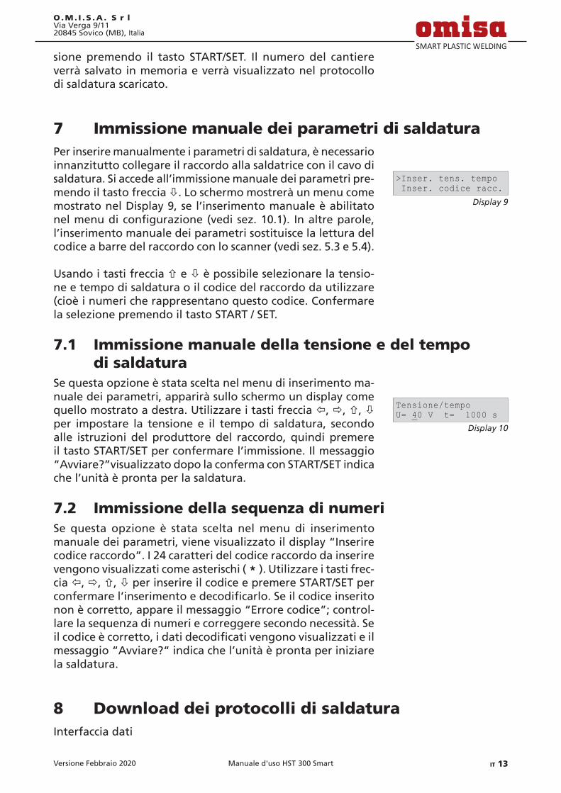
7 Immissione manuale dei parametri di saldaturaPer inserire manualmente i parametri di saldatura, è necessario innanzitutto collegare il raccordo alla saldatrice con il cavo di saldatura. Si accede all’immissione manuale dei parametri pre‑mendo il tasto freccia ò. Lo schermo mostrerà un menu come mostrato nel Display 9, se l’inserimento manuale è abilitato nel menu di configurazione (vedi sez. 10.1). In altre parole, l’inserimento manuale dei parametri sostituisce la lettura del codice a barre del raccordo con lo scanner (vedi sez. 5.3 e 5.4).
Usando i tasti freccia ñ e ò è possibile selezionare la tensio‑ne e tempo di saldatura o il codice del raccordo da utilizzare (cioè i numeri che rappresentano questo codice. Confermare la selezione premendo il tasto START / SET.
7.1 Immissione manuale della tensione e del tempo di saldatura
Se questa opzione è stata scelta nel menu di inserimento ma‑nuale dei parametri, apparirà sullo schermo un display come quello mostrato a destra. Utilizzare i tasti freccia ï, ð, ñ, ò per impostare la tensione e il tempo di saldatura, secondo alle istruzioni del produttore del raccordo, quindi premere il tasto START/SET per confermare l’immissione. Il messaggio “Avviare?”visualizzato dopo la conferma con START/SET indica che l’unità è pronta per la saldatura.
7.2 Immissione della sequenza di numeriSe questa opzione è stata scelta nel menu di inserimento manuale dei parametri, viene visualizzato il display “Inserire codice raccordo”. I 24 caratteri del codice raccordo da inserire vengono visualizzati come asterischi ( * ). Utilizzare i tasti frec‑cia ï, ð, ñ, ò per inserire il codice e premere START/SET per confermare l’inserimento e decodificarlo. Se il codice inserito non è corretto, appare il messaggio “Errore codice”; control‑lare la sequenza di numeri e correggere secondo necessità. Se il codice è corretto, i dati decodificati vengono visualizzati e il messaggio “Avviare?“ indica che l’unità è pronta per iniziare la saldatura.
8 Download dei protocolli di saldaturaInterfaccia dati
Display 9
>Inser. tens. tempo Inser. codice racc.
Display 10
Tensione/tempoU= 40 V t= 1000 s

Versione Febbraio 202014 IT Manuale d'uso HST 300 Smart
O.M. I . S .A . S r lVia Verga 9/11
20845 Sovico (MB), Italia
Porta interfaccia USB A per collegare supporti di memoria di massa (come una
chiavetta USB)
L’interfaccia è conforme alle specifiche USB versione 2.0 (velo‑cità dati massima di 480 megabit al secondo).
Importante
Prima di trasferire i dati, si consiglia vivamente di spegnere e riaccendere l’unità di saldatura. Se questo passaggio non viene eseguito, vi è il rischio di un errato o imperfetto trasferimento dei dati oppure i protocolli nell’unità di saldatura potrebbero venire danneggiati.
Importante
Quando si trasferiscono i protocolli di saldatura su una chiavetta USB, assicurarsi sempre di attendere fino a quando si mostra il messaggio “Scarico terminato” prima di disconnettere la chiavetta USB dall’unità. Se viene disconnessa troppo presto, l’unità potrebbe chie‑dere se si desidera eliminare i protocolli in memoria, sebbene non siano stati trasferiti correttamente. In questo caso, se si eliminano i contenuti della memoria, i protocolli di saldatura andrebbero irrevocabilmente persi e non sarebbero disponibili altrove.
8.1 SelezionedelformatodelfileIl collegamento del supporto di archiviazione fa apparire la schermata nella quale si può selezionare il formato del file con i protocolli di saldatura: un PDF con un estratto o una versione estesa del protocollo, il formato dati di saldatura DataWork o un file CSV. Utilizzando i tasti freccia ñ e ò, selezionare il tipo di file desiderato e confermarla premendo il tasto START/SET.
Il formato CSV consente l’importazione dei dati del protocollo in un database o un foglio di calcolo, a condizione che questa applicazione possa leggere il formato; questo è il caso, ad esempio, con il software Microsoft Excel.
L’opzione del protocollo di servizio non è importante per le normali operazioni. Nell’ambito del servizio assistito da com‑puter, questa lista elenca gli eventi relativi alle manutenzioni della saldatrice.
8.2 Download di tutti i protocolliDopo aver selezionato il tipo di file, la schermata successiva offre l’opzione “Stampa tutti i protocolli”. Selezionandola scaricherà tutti i protocolli di saldatura attualmente nella me‑moria di sistema nel formato file precedentemente selezionato.
Display 11
File DataWork>PDF prot. compresso

Versione Febbraio 2020 IT 15Manuale d'uso HST 300 Smart
O.M. I . S .A . S r lVia Verga 9/1120845 Sovico (MB), Italia
8.3 Download per numero di commessa, intervallo di date o protocolli
Dopo aver selezionato il tipo di file, la schermata successiva offre le opzioni “Per numero commessa”, “Per intervallo di date” e “Per intervallo di protocolli”. A seconda della selezione, i tasti freccia ñ e ò possono essere utilizzati per selezionare nelle commissioni attualmente nella memoria di sistema quella desiderata, di cui i protocolli devono essere scaricati oppure possono essere utilizzati i tasti freccia ï, ð, ñ, ò per inseri‑re una data di inizio e una data di fine, o il primo e l’ultimo rapporto, che definisce un intervallo di date o un intervallo di protocolli di cui i protocolli devono essere scaricati. Quando si preme il tasto START/SET, si trasferiscono i protocolli selezionati al supporto di archiviazione.
8.4 Processo del download dei protocolliIl download inizia automaticamente dopo che la selezione viene effettuata tra le varie opzioni. Attendere il trasferimento completo di tutti i protocolli selezionati e finché il messaggio “Scarico terminato” appare sullo schermo.
Se si verifica un problema durante il download, viene visua‑lizzato il messaggio “Non pronto”. Dopo che la causa del pro‑blema viene risolta, il download riprende automaticamente.
Info
Se la saldatrice riconosce un problema che non può essere risolto mentre è in corso il trasferimento dei dati, non riprende il processo e viene visualizzato il messaggio di errore “Scarico interrotto”. Per confer‑mare questo errore, premere il tasto START/SET.
8.5 Cancellazione dei dati dalla memoriaI dati dei protocolli in memoria possono essere eliminati solo dopo che tutti i protocolli di saldatura sono stati trasferiti, in‑dicato dal messaggio “Scarico terminato”. Quando il supporto di archiviazione è scollegato, viene visualizzato il messaggio “Cancellare protocolli”. Se il tasto START/SET viene premuto a questo punto, viene visualizzato un’ulteriore messaggio di conferma “Cancellare veramente?”, che deve essere confer‑mato premendo nuovamente il tasto START/SET. Quindi, i dati dei protocolli in memoria vengono eliminati.
8.6 Conservazione dei dati in memoriaQuando la stampante o il supporto di archiviazione è scolle‑gato, appare il messaggio “Cancellare protocolli”. Premere il tasto STOP/RESET per mantenere in memoria i dati dei proto‑colli correnti. Possono quindi essere stampati di nuovo.
Versione Febbraio 202016 IT Manuale d'uso HST 300 Smart
O.M. I . S .A . S r lVia Verga 9/11
20845 Sovico (MB), Italia
Importante
Prendere l’abitudine di gestire la memoria interna come descritto all’inizio della sez. 8, per mantenere l’integrità dei dati ed evitare qualsiasi cancellazione involontaria dei protocolli in memoria.
9 Informazioni sulla saldatrice
9.1 Visualizzazione delle caratteristiche dalla saldatriceLe informazioni tecniche chiave della saldatrice stessa possono essere visualizzate premendo il tasto ð alla schermata “Inserire codice barre”. Esse sono la versione del software, il numero di serie dell’unità, la data della successiva manutenzione pro‑grammata e il numero di protocolli attualmente disponibili non utilizzati. Per uscire dalla schermata, premere STOP/RESET.
Se la revisione pianificata è scaduta, viene visualizzato un messaggio di servizio sullo schermo non appena l’unità viene collegata all’alimentazione di rete o al generatore. Questo messaggio deve essere confermato premendo START/SET.
9.2 Misurazione della resistenzaQuando è stato premuto il tasto START/SET per avviare una saldatura, viene misurato il valore della resistenza del raccordo e comparato al valore immesso con la lettura del codice del rac‑cordo. Se la differenza tra i due valori è minore della tolleranza accettabile indicata nel codice, il processo di saldatura inizia. Se la differenza è maggiore della tolleranza preimpostata, la saldatrice interrompe la saldatura e visualizza il messaggio “Errore resistenza”. Inoltre, visualizza il valore di resistenza effettivo del raccordo collegato.
Il motivo di un errore della resistenza potrebbe essere lo scarso contatto e/o i terminali di collegamento usurati. Pertanto, se si verifica questo errore, controllare la corretta aderenza dei terminali e, se usurati, sostituirli con dei nuovi.
9.3 Interruttore di surriscaldamentoIl processo di saldatura si interrompe se la temperatura del trasformatore della saldatrice è troppo alta. L’interruttore di arresto per surriscaldamento interrompe la saldatura se il va‑lore della temperatura è troppo alto ed il tempo di saldatura rimanente è superiore a 800 secondi. Il display e il protocollo di saldatura mostrerà il messaggio “Surriscaldata”.
Versione Febbraio 2020 IT 17Manuale d'uso HST 300 Smart
O.M. I . S .A . S r lVia Verga 9/1120845 Sovico (MB), Italia
9.4 Indicazione di un guasto dell’alimentazione durante l’ultima saldatura
Il messaggio “Erogazione rete rotta all’ultima saldatura” indica che la precedente saldatura si è interrotta a causa di una mancanza di alimentazione. Il motivo potrebbe essere un generatore troppo debole o una prolunga troppo lunga o con sezione sottodimensionata o l’azionamento dell’interruttore automatico del dispositivo. La successiva saldatura è possibile dopo aver confermato il messaggio premendo STOP/RESET.
10 ConfigurazionedellasaldatriceCon il tag/tessera dell’operatore, la saldatrice può essere ricon‑figurata. Quando si preme il tasto MENU, il messaggio “Inserire codice menu” appare sullo schermo. Dopo che è stato letto dalla scheda, appare il menu di selezione nel Display 12.
In “Impostazioni”, i parametri relativi alla saldatrice stessa e il suo funzionamento possono essere impostati. In “Registra‑zioni”, i dati di tracciabilità che devono o non devono essere registrati e riportati nei protocolli possono essere abilitati o disabilitati. Il sottomenu desiderato viene selezionato usando le frecce ñ e ò. Quindi per accedere al sottomenu, premere il tasto MENU.
In entrambe le parti del menu di configurazione, utilizzare i tasti freccia ñ e ò per selezionare l’opzione di impostazione desiderata. Usare il tasto freccia ð per alternare tra “on” e “off” per questa opzione di configurazione.
Una “M” visualizzata accanto a un’opzione di impostazione indica che un sottomenu è accessibile qui con il tasto MENU.
Premere il tasto START/SET per confermare l’impostazione e salvarla nella memoria.
10.1 Comprensione del sottomenu "Impostazioni"“Scadenza patentino verificata ON” indica che il codice/paten‑
tino identificativo dell’operatore deve essere attivo e non scaduto (impostazione predefinita del periodo di validità 2 anni dall’emissione del codice), altrimenti l’operazione di saldatura non può essere avviata, “OFF”, che la validità del codice non viene verificata del tutto.
“Controllo memoria ON” indica che quando la memoria di sistema è piena di protocolli, l’unità verrà bloccata finché i protocolli verranno stampati o scaricati, “OFF”, che fun‑ziona ma i protocolli più vecchi verranno sovrascritti.
“Impostazione manuale ON” indica che l’inserimento manuale
Display 12
>Impostazioni -M- Registrazioni -M-
Display 13
>Scad. patentino OFF Contr. memoria ON

Versione Febbraio 202018 IT Manuale d'uso HST 300 Smart
O.M. I . S .A . S r lVia Verga 9/11
20845 Sovico (MB), Italia
dei parametri di saldatura (vedi sez. 7) è possibile, “OFF”, che l’inserimento manuale non è attivo.
“Menu del codice operatore M ” indica che premendo il tasto MENU, si può accedere a un sottomenu che consente di determinare quando il codice operatore, se abilitato alle “Registrazioni”, deve essere inserito: sempre “x”, ovvero prima di ogni singola saldatura, prima della prima salda‑tura dopo l’avvio dell’unità o solo “ogni giorni”, ovvero prima della prima saldatura di un nuovo giorno/data.
“Lingua M ” indica che premendo il tasto MENU, si può ac‑cedere a un sottomenu per selezionare la lingua utilizzata al display e nei protocolli di saldatura (vedi sez. 10.1.1).
“Data/ora M ” indica che premendo il tasto MENU, si può accedere a un sottomenu per l’impostazione dell’orologio (vedi sez. 10.1.2).
“Unità di temperatura M ” indica che premendo il tasto MENU, si può accedere a un sottomenu per la selezione dei gradi centigradi o Fahrenheit come unità per la tem‑peratura.
“Numero di inventario M ” indica che premendo il tasto ME‑NU, si può accedere a un sottomenu per inserire il numero con il quale l’unità è inventariata dalla società.
“Numero di etichette M ” indica che premendo il tasto MENU, si può accedere a un sottomenu per inserire il numero di etichette che vengono stampate automaticamente dopo la saldatura con la stampante per etichette opzionale, se collegata.
10.1.1 Selezione della lingua di visualizzazioneQuando viene selezionato il sottomenu “Lingua”, lo schermo cambia e riproduce il Display 14.
Utilizzare i tasti freccia ñ e ò per selezionare una delle opzio‑ni, “Deutsch”, “English”, “Français” e confermare premendo il tasto START/SET.
10.1.2 Impostazione dell'orologioQuando viene selezionato il sottomenu “Data/ora”, lo schermo cambia e appare il Display 15. L’ora del giorno e la data possono essere impostate utilizzan‑do la tastiera.“Ora”, “Minuto”, “Giorno”, “Mese” e “Anno” vengono impostati separatamente. Premere il tasto START/ SET per confermare l’impostazione.
10.1.3 Selezione dell'unità di temperaturaL’unità di temperatura (Celsius o Fahrenheit) può essere sele‑zionata in un sottomenu analogo alla selezione della lingua (vedi sez. 10.1.1).
Display 14
>Deutsch English
Display 15
Data/ora21.06.13 14:28
Versione Febbraio 2020 IT 19Manuale d'uso HST 300 Smart
O.M. I . S .A . S r lVia Verga 9/1120845 Sovico (MB), Italia
10.2 Comprensione del sottomenu "Registrazioni"“Codice operatore ON” indica che il codice d’identificazione
dell’operatore deve essere inserito come impostato con il “Menu del codice operatore”, “OFF”, che questo non è possibile.
”Numero di commessa ON” indica che il numero della com‑messa (lavoro, commissione, cantiere) dovrà essere inserito o confermato prima di ogni nuova saldatura, “OFF”, che non viene richiesto il suo inserimento.
“Dati aggiuntivi ON” indica che i dati aggiuntivi devono es‑sere inseriti o confermati prima di ogni nuova saldatura, “OFF”, che l’operatore non è tenuto ad inserirli.
“Codice raccordo ON” indica che il secondo, il cosiddetto co‑dice tracciabilità del raccordo per elettrofusione deve es‑sere inserito prima di ogni saldatura, “OFF”, che questo non è possibile.
“Codice tubo ON” indica che i codici di entrambi i tubi/com‑ponenti (codici di saldatura e tracciabilità conformi ISO) devono essere inseriti prima di ogni saldatura, “OFF”, che ciò non è possibile.
“Lunghezza tubo ON” indica che la lunghezza di entrambi i tubi/componenti deve essere inserita prima di ogni salda‑tura, “OFF”, che ciò non è possibile.
“Condizioni climatiche ON” indica che le condizioni meteo‑rologiche devono essere selezionate in un elenco prima di ogni saldatura, “OFF”, che questo non è possibile.
“Nome impresa ON” significa che la società che esegue il lavoro di installazione deve essere inserita prima di ogni saldatura, “OFF”, che ciò non è possibile.
“Stampare etichette M ” indica che premendo il tasto MENU, si può accedere ad un sottomenu per iniziare a stampare una o più etichette con riferimento a una data operazione di saldatura, con la stampante per etichette opzionale.
Info
Tutti i dati possono anche essere letti attraverso un codice a barre con lo scanner, a condizione che tale codice a barre sia disponibile.
11 Panoramica delle funzioni di automonitoraggio
11.1 Errori durante l'immissione dei dati
11.1.1 Errore codiceSi è verificato un inserimento errato, l’etichetta del codice è danneggiata o vi è un errore nella simbologia del codice o la lettura del codice è errata.
Display 16
Codic.operatore ON>Numero commessa ON
Versione Febbraio 202020 IT Manuale d'uso HST 300 Smart
O.M. I . S .A . S r lVia Verga 9/11
20845 Sovico (MB), Italia
11.1.2 Contatto interrottoNon vi è un contatto elettrico correttamente stabilito tra la saldatrice e il raccordo (controllare il morsetto a pressione sul raccordo) o la resistenza è difettosa.
11.1.3 SottotensioneLa tensione in ingresso è inferiore a 175 volt. Regolare la ten‑sione in uscita del generatore.
11.1.4 SovvratensioneLa tensione in ingresso è superiore a 290 volt. Ridurre la ten‑sione in uscita del generatore.
11.1.5 Saldatrice surriscaldataLa temperatura del trasformatore è troppo alta. Lasciar raf‑freddare la saldatrice per circa 1 ora.
11.1.6 Errore di sistemaATTENZIONE!La saldatrice deve essere scollegata immediatamente sia dall’a‑limentazione che dal raccordo. L’auto-test ha rilevato un errore nel sistema. La saldatrice non deve più essere accesa e deve essere inviata a un centro autorizzato per essere controllata e riparata.
11.1.7 Errore temperatura ambienteLa temperatura ambiente misurata è al di fuori del range di funzionamento dell’unità di saldatura, cioè inferiore a – 20°C (– 4°F) o oltre + 50°C (+ 140°F).
11.1.8 Rilevazione temperatura difettosaIl sensore della temperatura ambientale sul cavo di saldatura è danneggiato o difettoso.
11.1.9 Orologio difettosoL’orologio di sistema interno non funziona correttamente o è difettoso. Ripristinarlo o inviare la saldatrice al produttore per controllo e assistenza.
11.1.10 Manutenzione scadutaLa data di manutenzione consigliata per la saldatrice è scaduta. Il messaggio di scadenza deve essere confermato premendo il tasto START/SET. Inviare la saldatrice al produttore o un punto di assistenza autorizzato per l’assistenza e il controllo.

Versione Febbraio 2020 IT 21Manuale d'uso HST 300 Smart
O.M. I . S .A . S r lVia Verga 9/1120845 Sovico (MB), Italia
11.1.11 Errore inserimentoUn codice inserito non è corretto. All’inserimento manuale dei parametri di saldatura, nessun tempo di saldatura è stato inserito. È stato selezionato un valore non corretto nell’impo‑stazione della data.
11.1.12 Memoria protocolli pienaLa memoria di sistema è piena di protocolli di saldatura. Stam‑pa o scarica i rapporti in memoria o cambia il controllo della memoria per OFF. Senza controllo della memoria, un nuovo protocollo sovrascrive il protocollo più vecchio esistente.
11.1.13 Scarico interrottoDurante il trasferimento dei dati o la stampa, si è verificata un errore che non è stato possibile risolvere.
11.2 Errori durante la saldaturaTutti gli errori che si verificano mentre la saldatura è in corso, vengono segnalati da un allarme acustico.
11.2.1 SottotensioneLa tensione in ingresso è inferiore a 175 volt. Se la condizione di errore persiste per più di 15 secondi, la saldatura sarà inter‑rotta. Se la tensione scende al di sotto di 170 volt, il processo di saldatura si interromperà immediatamente.
11.2.2 SovvratensioneLa tensione in ingresso è superiore a 290 volt. Se la condizione di errore persiste per più di 15 secondi, il processo di saldatura sarà interrotto.
11.2.3 Errore resistenzaIl valore della resistenza del raccordo collegato è fuori tolle‑ranza secondo ciò che si è letto nel codice a barre.
11.2.4 Errore frequenzaLa frequenza della tensione in ingresso è fuori tolleran‑za (42 Hz ‑ 69 Hz).
11.2.5 Errore tensioneControllare la tensione e la corrente del generatore. La ten‑sione in uscita non corrisponde al valore letto in precedenza; la saldatrice deve essere inviata al produttore per il controllo.

Versione Febbraio 202022 IT Manuale d'uso HST 300 Smart
O.M. I . S .A . S r lVia Verga 9/11
20845 Sovico (MB), Italia
11.2.6 Corrente molto bassaIl messaggio viene visualizzato se c’è un momentaneo guasto di corrente o se la corrente diminuisce di oltre il 15% al secondo per 3 secondi.
11.2.7 Corrente molto altaIl valore della corrente in uscita è in eccesso; possibili cause: cortocircuito nella resistenza o nel cavo di saldatura. Durante la fase iniziale la soglia di interruzione superiore equivale a 1,18 volte del valore all’avvio, in ogni altro caso, il limite superiore dipende dal valore di carico e viene calcolato come la corrente all’avvio più il 15%.
11.2.8 Blocco emergenzaLa saldatura è stata interrotta premendo il tasto STOP/RESET.
11.2.9 Errore contatto spiraIl valore di corrente dinamica durante la saldatura differisce di più del 15% dal valore richiesto, indicando un corto circuito nella resistenza.
11.2.10 Erogazione rete rotta all’ultima saldaturaL’ultima saldatura è incompleta. La saldatrice è stata discon‑nessa dall’alimentazione mentre era in corso la saldatura. Per continuare a utilizzare la saldatrice, questo errore deve essere confermato premendo il tasto STOP/RESET (vedi anche sez. 9.4).
12 SpecifichetecnicheIntervallo operativo raccordi fino a 160 mmTensione nominale 230 VFrequenza 50 Hz / 60 HzPotenza 1680 VA in ciclo di 80%Grado di protezione IP X4Corrente primaria max. 16 ARange di temp. ambiente – 20°C a + 60°C (– 4°F a + 140°F)Tensione in uscita 8 V ‑ 48 VCorrente in uscita max. 65 AMemoria di protocolli 500 protocolli di saldaturaPorta interfaccia dati USB v 2.0 (480 mbit/s) (vedere anche le informazioni sulle porte dati all‘inizio della sez. 8)
Tolleranze: Temperatura ± 5 % Tensione ± 2 % Corrente ± 2 % Resistenza ± 5 %

Versione Febbraio 2020 IT 23Manuale d'uso HST 300 Smart
O.M. I . S .A . S r lVia Verga 9/1120845 Sovico (MB), Italia
13 Contatti per l'assistenza e la riparazione O.M.I.S.A. S r l Via Verga 9/11 Tel.: +39 039 23 23 028 20845 Sovico (MB), Italia
Web: www.omisa.it Mail: [email protected]
Info
Ci riserviamo il diritto di modificare le specifiche tec‑
niche del prodotto senza preavviso.
14 Accessori/parti del prodottoAdattatore a gomito a pressione 4,0 - 4,7 90°
216 ‑ 010 ‑ 440Borsa adattatori 216 ‑ 030 ‑ 310Tag/scheda ID dell’operatore 216 - 080 - 031Penna scanner 216 ‑ 030 ‑ 270Cavo USB 300 - 010 - 167Software DataWork per Windows 216 - 080 - 505Chiavetta USB 300 - 010 - 154

La versione tedesca qui inclusa è il testo originale del manuale, dal quale vennero elaborate le incluse traduzioni.The German version of the manual enclosed herein is the original copy, reflected in the translations herein.Inliegende deutsche Fassung der Anleitung ist der Urtext, welchen inliegende Übersetzungen wiedergeben.
La versión alemana adjunta está el texto original de las instrucciones, que también representan las traducciones de esta.

Version February 2020 EN 3HST 300 Smart User’s Manual
O.M. I . S .A . S r lVia Verga 9/1120845 Sovico (MB), Italy
Contents1 Introduction ................................................................................. 52 Safety Messages ........................................................................... 52.1 Using the Correct Connection Terminal ..................................... 52.2 Improper Use of the Welding and Power Supply Cables .......... 62.3 Securing the Fitting and the Joint .............................................. 62.4 Cleaning the Product ................................................................... 62.5 Opening the Unit ......................................................................... 62.6 Extension Cables on the Worksite .............................................. 62.7 Checking the Product for Damage ............................................. 62.8 Data Interface Cover Cap ............................................................ 72.9 PowerSupplySpecifications ........................................................ 72.9.1 Mains Power Supply .................................................................... 72.9.2 Generator Power Supply ............................................................. 73 Service and Repair ....................................................................... 73.1 General ......................................................................................... 73.2 Transport, Storage, Shipment ..................................................... 84 Principles of Operation ................................................................ 85 Check-out and Operation ............................................................ 95.1 Turning the Welding Unit on ...................................................... 95.2 Entering the Welder ID Code ...................................................... 95.3 Connecting the Fitting .............................................................. 105.4 Reading the Fitting Code with a Handheld Scanner ............... 105.5 Starting the Welding Process .................................................... 115.6 Welding Process ......................................................................... 115.7 End of Welding .......................................................................... 115.8 Aborted Welding Process .......................................................... 115.9 Cooling Time .............................................................................. 115.10 Returning to the Start of Parameter Input .............................. 125.11 Using ViewWeld to Manage Logged Welding Reports and Print Tags ............................................................................ 126 Additional Information in the Welding Report ....................... 126.1 EnteringPreformattedandUser-definedTraceabilityData ... 126.2 Entering or Changing the Job Number .................................... 137 Entering Welding Parameters Manually .................................. 137.1 Manually Entering Welding Voltage and Time ........................ 137.2 Entering the String of Numbers ................................................ 148 Downloading the Reports ......................................................... 148.1 Selecting the File Format ........................................................... 148.2 Downloading All Reports .......................................................... 158.3 Downloading by Commission Number, Date or Report Range 158.4 Understanding the Report Download Process ......................... 158.5 Deleting Data from Memory ..................................................... 158.6 Keeping Data in Memory .......................................................... 16

Version February 20204 EN HST 300 Smart User’s Manual
O.M. I . S .A . S r lVia Verga 9/11
20845 Sovico (MB), Italy
9 Dedicated Welding Unit Information ....................................... 169.1 Displaying Characteristics of the Welding Unit ....................... 169.2 Measuring Resistance ................................................................ 169.3 Overheating Switch ................................................................... 179.4 Indication of Power Supply Failure at the Last Welding ......... 1710 ConfiguringtheWeldingUnit .................................................. 1710.1 Understanding the “Settings” Sub-menu ................................ 1710.1.1 Selecting the Display Language ................................................ 1810.1.2 Setting the Clock ........................................................................ 1810.1.3 Setting the Buzzer Volume ....................................................... 1910.1.4 Selecting the Temperature Unit ................................................ 1910.2 Understanding the “Recording” Sub-menu ............................. 1911 Self-Monitoring Functions Overview ........................................ 1911.1 Errors During Data Input ........................................................... 1911.1.1 Code Error .................................................................................. 1911.1.2 No Contact ................................................................................. 1911.1.3 Low Voltage ............................................................................... 2011.1.4 Overvoltage ................................................................................ 2011.1.5 Overheated ................................................................................ 2011.1.6 System Error ............................................................................... 2011.1.7 Temperature Error ..................................................................... 2011.1.8 Temperatur Sensor Defective .................................................... 2011.1.9 Clock Error .................................................................................. 2011.1.10 Unit to Service ............................................................................ 2011.1.11 Input Error .................................................................................. 2011.1.12 Memory Full ............................................................................... 2111.1.13 Download Cancelled .................................................................. 2111.2 Errors During Welding ............................................................... 2111.2.1 Low Voltage ............................................................................... 2111.2.2 Overvoltage ................................................................................ 2111.2.3 Resistance Error .......................................................................... 2111.2.4 Frequency Error .......................................................................... 2111.2.5 Voltage Error .............................................................................. 2111.2.6 Low Current ............................................................................... 2111.2.7 Excess Current ............................................................................ 2211.2.8 Emergency Off ........................................................................... 2211.2.9 Heater Coil Error ........................................................................ 2211.2.10 Power Supply Failure at Last Welding ...................................... 2212 TechnicalSpecifications ............................................................. 2213 Service and Repair Contact ....................................................... 2314 Accessories/Parts for the Product .............................................. 23

Version February 2020 EN 5HST 300 Smart User’s Manual
O.M. I . S .A . S r lVia Verga 9/1120845 Sovico (MB), Italy
1 IntroductionDear Customer:
Thank you very much for purchasing our product. We are confident that it will meet your expectations.
The HST 300 Smart Welding Unit is designed exclusively for welding plastic pipe fittings sized max. 160 mm according to the electrofusion process.
The product was manufactured and checked according to state-of-the-art technology and widely recognized safety regulations and is equipped with the appropriate safety features.
Before shipment, it was checked for operation reliability and safety. In the event of errors of handling or misuse, however, the following may be exposed to hazards:• theoperator’shealth,• theproductandotherhardwareoftheoperator,• theefficientworkoftheproduct.
All persons involved in the installation, operation, main-tenance, and service of the product have to• beproperlyqualified,• operatetheproductonlywhenobserved,• readcarefullyandconformtotheUser’sManualbefore
working with the product.
Thank you.
2 Safety Messages
2.1 Using the Correct Connection TerminalUse the appropriate connection terminal that is compat-ible with the fitting type used. Be sure the contact is firmly established and do not use connection terminals or terminal adapters that are burnt or not designed for the intended use.
2.2 Improper Use of the Welding and Power Supply Cables
Do not carry the product by its cables and do not pull the

Version February 20206 EN HST 300 Smart User’s Manual
O.M. I . S .A . S r lVia Verga 9/11
20845 Sovico (MB), Italy
power cord to unplug the unit from the socket. Protect the cables against heat, oil, and cutting edges.
2.3 Securing the Fitting and the JointUse positioner clamps or a vice to secure the fitting and the joint to be made before welding. The fitting manufac-turer’s installation instructions, local and national regula-tions have to be respected in all cases.
A welding process must never be repeated with the same fitting, since this may cause parts under power to be ac-cessible to the touch.
2.4 Cleaning the ProductThe product must not be sprayed with or immersed in water.
2.5 Opening the Unit
Caution
The cover of the product may be removed only by specialized staff of the manufacturer or of a service shop properly trained and approved by it.
2.6 Extension Cables on the WorksiteTo extend power cord length, use exclusively properly ap-proved extension cables that are labeled as such and have the following conductor sections:up to 20 m: 1.5 mm² (2.5 mm² recommended); Type H07RN-Fover 20 m: 2.5 mm² (4.0 mm² recommended); Type H07RN-F
Caution
When using the extension cable, it has always to be rolled off completely and lie fully extended.
2.7 Checking the Product for DamageBefore every use of the product, check safety features and possibly existing parts with minor damage for proper function. Make sure that the push-on connection terminals work properly, that contact is fully established, and that the contact surfaces are clean. All parts have to be installed correctly and properly conform to all conditions in order for the product to function as intended. Damaged safety features or functional parts should be properly repaired or replaced by an approved service shop.
2.8 PowerSupplySpecifications
2.8.1 Mains Power SupplyUtility suppliers’ wiring requirements, occupational safety

Version February 2020 EN 7HST 300 Smart User’s Manual
O.M. I . S .A . S r lVia Verga 9/1120845 Sovico (MB), Italy
rules, applicable standards, and national codes have to be respected.
Caution
When using power distributions on the worksite, rules for the installation of earth-leakage circuit breakers (RCD) have to be respected, and operation requires an installed breaker.
Generator or mains power fuse protection should be 16 A (slow blow). The product has to be protected against rain and humidity.
2.8.2 Generator Power SupplyThe required nominal generator capacity as determined by the power supply requirement of the largest fitting to be welded depends on the power supply specifications, the environment conditions, and the generator type itself including its control/regulation characteristics.
Nominal output power of a generator 1-phase, 220 - 240 V, 50/60 Hz: d 20.....d 160 3.2 kW
Start the generator first, then connect the welding unit. The idle voltage should be set to approx. 240 volts. When turning the generator off, disconnect the welding unit first.
Important
The working output power of the generator de-creases by about 10% per 1,000 m of altitude. During the welding process no other device con-nected to the same generator should be operated.
3 Service and RepairAs the product is used in applications that are sensitive to safety considerations, it may be serviced and repaired only by the manufacturer or its duly authorized and trained partners. Thus, constantly high standards of operation quality and safety are maintained.
Failure to comply with this provision will dispense the manufacturer from any warranty and liability claims for the product, including any consequential damage.
When serviced, the unit is upgraded automatically to the technical specifications of the product at the moment it is serviced, and we grant a three-month functional warranty on the serviced unit.

Version February 20208 EN HST 300 Smart User’s Manual
O.M. I . S .A . S r lVia Verga 9/11
20845 Sovico (MB), Italy
We recommend having the product serviced at least every twelve months.
Any provisions in the law pertaining to an electrical safety inspection have to be complied with.
4 Principles of OperationThe HST 300 Smart allows welding electrofusion fittings that feature a bar code. Every fitting is provided with a tag with one or two bar codes on it. The structure of this code is internationally standardized. The first code, encoding the data on proper welding, complies with ISO 13950, the second code, if present, encoding the component trace-ability data, complies with ISO 12176.
The microprocessor-controlled HST 300 Smart Welding Unit• controlsandmonitors theweldingprocess ina fully
automated fashion,• determinesweldingdurationdependingonambient
temperature,• showsallinformationonthedisplayinplaintext.
All data that are relevant for the weld or for traceability are saved to the internal memory and can be sent to a USB stick.
Welding data transfer is enabled through an interface of the USB A type, which is compatible with a USB stick.
Further Optional Accessories• PC software for downloading and archiving data on
PC (for all common Windows operating systems)• Label tag printer for printing an identifier label for
the new joint right after the welding operation• USB stick for data transfer from the welding unit on
the worksite to the printer or PC in your office (see details at the end of this booklet)
5 Check-out and Operation• Tooperatetheweldingunit,besurethatitissetona
proper, level surface.• Besurethatpowersupply/generatorprotectionis16A
(slow blow).• Plug the power supply cord into themains power
supply or the generator.• ReadandcomplywiththeUser’sManualofthegen-
erator, if applicable.

Version February 2020 EN 9HST 300 Smart User’s Manual
O.M. I . S .A . S r lVia Verga 9/1120845 Sovico (MB), Italy
5.1 Turning the Welding Unit onAfter connecting the power supply cable to mains power or a generator, turn the welding unit on using the On/Off switch. This causes Display 1 to show.
Then the screen changes to Display 2. While it is showing, the welder is ready for the connection of the electrofu-sion fitting.
Caution
CAUTION in case of System Errors! If during the auto-test that the unit performs at
start-up, an error is detected, a “System Error” mes-sage shows on the display. When this happens, the welding unit has to be disconnected immediately from the power suppy and the fitting, and it has to be shipped to the manufacturer for repair.
5.2 Entering the Welder ID CodeThe welding unit can be configured to ask for the welder identification code before the fitting code is entered. The display screen then shows the message “Enter Welder Code.” (Later this screen can be accessed by a quick access routine; see Sect. 6.1.) The numeric code can be entered either by reading it from a tag with the scanner or by using the ï, ð, ñ, ò cursor keys. Whether the welder identification code has to be entered and if so, when or how often, is determined in the “Settings” sub-menu of the configuration menu (see Sect. 10.1).
When the welder code is read from a bar code using the scanner, an audible signal confirms this and the screen shows the read code and switches to the next input display. When the code is entered manually, it is saved by press-ing the START/SET key. If the code entered is not correct, a “Code Error” message appears; check the sequence of numbers and correct as needed. If the code entered is cor-rect, it is saved to system memory and inserted into the welding reports to be downloaded.
Only an ISO standard-compliant welder identification code is accepted by the unit. If the welder code feature is dis-abled, the input screen for the welder code will not show.
5.3 Connecting the FittingConnect the connection terminals to the fitting and check for proper contact. Use terminal adapters if needed. The contact surfaces of the cable connection terminals or adapt-ers and the fitting have to be clean. Dirty terminals may lead to improper welding and also to overheated and fused
Display 1
OMISA HST300 Smart
Display 2
14:32:11 21.10.12No Contact
Display 3
Welder Code********************
Version February 202010 EN HST 300 Smart User’s Manual
O.M. I . S .A . S r lVia Verga 9/11
20845 Sovico (MB), Italy
connection terminals. Protect the cable connectors against getting dirty at all times. Terminals and push-on adapters should be considered consumables and, therefore, have to be checked before every welding operation and replaced if damaged or dirty.
When the fitting is connected, instead of the “No Contact” message (see Display 2) the number of the next welding report appears, e.g., “Prot. No.: 0015.”
5.4 Reading the Fitting Code with a Handheld Scanner
Only the bar code on the tag sticking on the fitting to be welded may be used. It is not acceptable to read the fitting code tag of a fitting of a different kind if the intended one is damaged or unreadable.
Read the fitting code by holding the scanner in front of the bar code at a distance of 5 to 10 cm (2 to 4 inches), where the red line indicates the reading area. Then push the reading button. If the data are correctly read, the weld-ing unit confirms this by an audible signal and displays the decoded data on the screen (see Display 4).
Info
The displayed values are the nominal welding
parameters contained in the fitting bar code or computed based on these data. They are displayed before the actual resistance of the electrofusion fitting is measured. This means that even when the showing ohm value is o.k., a resistance error may still be detected (see Sect. 9.2). Only when the welding process starts, the display shows the actual, measured welding parameters.
The “Start ?” message means that the unit is ready to start the welding process. Check the read data and if you see that they are erroneous, delete them by pressing the STOP/RESET key. The read data are also deleted if the welding unit is disconnected from the fitting.
5.5 Starting the Welding Process
Info
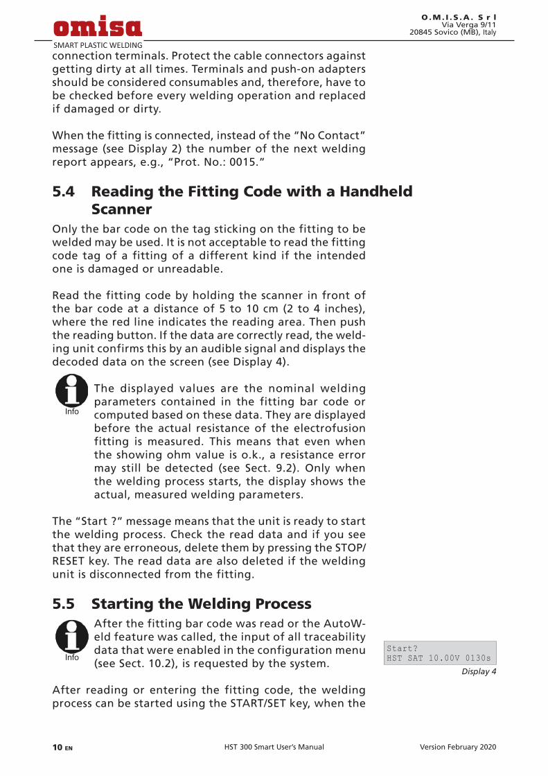
After the fitting bar code was read or the AutoW-eld feature was called, the input of all traceability data that were enabled in the configuration menu (see Sect. 10.2), is requested by the system.
After reading or entering the fitting code, the welding process can be started using the START/SET key, when the
Display 4
Start?HST SAT 10.00V 0130s

Version February 2020 EN 11HST 300 Smart User’s Manual
O.M. I . S .A . S r lVia Verga 9/1120845 Sovico (MB), Italy
“Start ?” message is displayed and there is no indication of a problem.
Pressing the START/SET key will trigger a confirmation mes-sage “Pipe treated?,” which in turn requires a confirmation with the START/SET key to start the welding proper.
5.6 Welding ProcessThe welding process is monitored for its entire duration applying the welding parameters contained in the fitting code. Along with the actual (left) and nominal (right) weld-ing time, the welding voltage, the resistance, and the weld-ing current are displayed in the lower line of the screen.
5.7 End of WeldingThe welding process ends successfully if the actual weld-ing time corresponds to the nominal welding time and the buzzer can be heard twice.
5.8 Aborted Welding ProcessThe welding process has failed if a plain-text error is dis-played on the screen and the audible signal buzzes con-tinuously. An error has to be acknowledged by pressing the STOP/RESET key.
5.9 Cooling TimeThe cooling time as given in the fitting manufacturer’s instructions has to be respected. If the bar code provided by the fitting manufacturer contains cooling time data, it will be displayed at the end of the welding process and will be counted down to zero. This countdown can be ac-knowledged and canceled at any time by the STOP/RESET key. However, note that for that time the pipe fitting joint which is still warm must not be subjected to an external force. No cooling time is displayed if the fitting code does not contain any such information.
5.10 Returning to the Start of Parameter InputAfter welding is finished, disconnecting the welded fitting from the unit or pressing the STOP/RESET key will reset the unit back to the start of entering the welding parameters.
5.11 Using ViewWeld to Manage Logged Welding Reports and Print Tags
The ViewWeld feature offers viewing an abstracted ver-sion of the welding reports recorded during the welding
Display 5
0009sec 0090sec10.00V 1.61Ω 6.21A

Version February 202012 EN HST 300 Smart User’s Manual
O.M. I . S .A . S r lVia Verga 9/11
20845 Sovico (MB), Italy
processes and printing it as a label tag to be affixed to the joint on the optionally available tag printer. The ViewWeld abstract shows the report number, the date and time of the welding and the welding parameters along with an evaluation of the quality of the joint/welding operation (see Display 6; only two lines appear on the screen, to see those not shown, press the ñ and ò keys), where the first displayed abstract is that of the last performed welding operation.
To call the ViewWeld abstract of a welding report, press the ñ key in the bar code input screen (see Display 2). Browsing through the saved welding reports is then possible by press-ing the ï or ð cursor keys. To print a tag of the welding operation of which the abstract is currently displayed, the label tag printer has to be connected to the welder. Then press the START/SET key in the ViewWeld screen.
6 Additional Information in the Welding ReportEvery welding report saved to system memory, which can be downloaded as a PDF report file or in the DataWork format, contains a number of welding and traceability data that the operator can decide to enter or not to enter in the set-up menu.
6.1 EnteringPreformattedandUser-definedTraceability Data
All traceability data enabled in the configuration menu at “Data Recording” (see Sect. 10) have to be entered before the welding process. The welding unit prompts the user to enter them either before or after entering the fitting bar code (see Display 2). Depending on what data is entered, either its repeated input is mandatory (e. g., the welder ID code; see Sect. 5.2) or previously entered data can be changed and confirmed or confirmed without changes (e. g. the commission number; see Sect. 6.2).
Certain traceability data can also be accessed quickly, via a selection screen, by pressing the ï cursor key (see Dis-play 7), either for viewing or for entering or changing/confirming them.
6.2 Entering or Changing the Job NumberThe commission number input screen is shown by the unit before welding or accessed by the user in the quick access screen (Display 7). It can be entered using the ï, ð, ñ, ò cursor keys or by reading it from a bar code using the scan-
Display 6
0015 24.02.13 09:33M/B MON HST 4500058s 025.0V 1.57ΩWelding OK
Display 7
>Welder ID Code Enter Job No.
Display 8
Enter Job No.********************
Version February 2020 EN 13HST 300 Smart User’s Manual
O.M. I . S .A . S r lVia Verga 9/1120845 Sovico (MB), Italy
ner. The maximum length is 32 characters. Confirm your input by pressing the START/SET key. The job number will be saved to memory and will appear in the downloaded welding report.
7 Entering Welding Parameters ManuallyTo be able to enter the welding parameters manually, you have first to connect the fitting to the welding unit with the welding cable. The manual input of the parameters can then be accessed by pressing the ò arrow key. The screen will show a menu as reproduced in Display 9, provided manual input is enabled in the configuration menu (see Sect. 10.1). In other words, the manual parameter input replaces reading the bar code of the fitting with a scanner.
Using the arrow keys ñ and ò you can select “Enter Volt-age/Time” or “Enter Fitting Code” (i.e., the numbers that represents the code of the fitting to be used). Confirm your selection by pressing the START/SET key.
7.1 Manually Entering Welding Voltage and TimeIf this option was chosen in the manual parameter input menu, a display like the one to the right appears on the screen. Use the ï, ð, ñ, ò cursor keys to set the welding voltage and the welding time, according to the fitting manufacturer’s instructions, then press the START/SET key to confirm your input. The “Start ?” message displayed after the confirmation by START/SET indicates that the unit is ready for welding.
7.2 Entering the String of NumbersIf this option was chosen in the manual parameter input menu, the “Enter Fitting Code” display shows. The 24 characters of the fitting code to be entered display as asterisks ( * ). Use the ï, ð, ñ, ò cursor keys to enter the code and press START/SET to confirm your input and have it decoded. If the code entered is not correct, a “Code Error” message appears; check the string of numbers and correct as needed. If the code is correct, the decoded data is displayed, and the “Start ?” message indicates that the unit is ready to start welding.
8 Downloading the ReportsInterface
Display 9
>Enter Voltage/Time Enter Fitting Code
Display 10
Voltage/TimeU= 40 V t= 1000 s

Version February 202014 EN HST 300 Smart User’s Manual
O.M. I . S .A . S r lVia Verga 9/11
20845 Sovico (MB), Italy
USB A Interface Port for connecting USB mass storage media (such as a
memory stick)
The interface port complies with the USB version 2.0 specification (i.e., maximum data rate of 480 megabits per second).
Important
Before transferring data, it is highly recommended to switch the welding unit off and on again. If this fails to happens, there is a risk of data transfer failure, or reports in the welding unit may be cor-rupted.
Important
When transferring welding reports to a USB stick,
always be sure to wait until the display shows the “Download finished” message before you discon-nect the USB stick from the product. If you discon-nect it too early, the unit may ask you whether you want to delete the reports in memory, although they were not properly transferred. In this case, if you delete the contents of the report memory, the welding reports would be irrevocably lost and would not be available elsewhere either.
8.1 Selecting the File FormatConnecting the storage media causes the the screen to appear in which the format of the output file with the welding reports can be selected: a PDF file with an ab-stracted or extended version of the report, the format of the welding data management application DataWork or a CSV file. Using the ñ and ò arrow keys, select the file type you need and confirm your selection by pressing the START/SET key.
The CSV format enables import of the report data into a database or spreadsheet application, provided this ap-plication can read the format; this is the case, e.g., with Microsoft Excel.
The Service Report option is not important for normal operation. In the scope of computer-assisted unit service, this report lists the events related to the maintenance of the welding unit.
8.2 Downloading All ReportsAfter the file type was selected, the next screen offers a “Print All Reports” option. Selecting it will download all
Display 11
DataWork File>PDF Abstract

Version February 2020 EN 15HST 300 Smart User’s Manual
O.M. I . S .A . S r lVia Verga 9/1120845 Sovico (MB), Italy
welding reports currently in system memory in the previ-ously selected file format.
8.3 Downloading by Commission Number, Date or Report Range
After the file type was selected, the next screen offers a “By Commission Number,” a “By Date Range,” and a “By Report Range” options. Depending on the selection, the ñ and ò arrow keys can be used to select from the com-missions currently in system memory the desired one, of which the reports should be downloaded, or the ï, ð, ñ, ò cursor keys can be used to enter a start date and an end date, or the first and the last report, that define a range of dates or a range of reports of which the reports should be downloaded. When you press the START/SET key, you cause the selected reports to be transferred to the stor-age media.
8.4 Understanding the Report Download ProcessThe download starts automatically after a selection was made among the options. Wait for all the selected reports to transfer and the “Download completed” message to appear on the screen.
If a problem occurs while the download is in progress, a “Not ready” message shows. After the problem condition is cleared, the download resumes automatically.
Info
If the welding unit recognizes a problem that cannot be cleared while the data transfer is in progress, it does not resume the process and dis-plays a “Download cancelled” error message. To acknowledge this error, press the START/SET key.
8.5 Deleting Data from MemoryThe report data in memory can be deleted only after all welding reports were transferred, which is indicated by the “Download completed” message. When the storage media is unplugged, a “Delete Memory” message appears. If the START/SET key is pressed at this point, a further confirma-tion message “Delete Memory, sure?” is shown, which has to be confirmed by pressing the START/SET key once again. Then, the report data in memory are deleted.
8.6 Keeping Data in MemoryWhen the cable or storage media is unplugged, a “Delete Memory” message is displayed. Press the STOP/RESET key
Version February 202016 EN HST 300 Smart User’s Manual
O.M. I . S .A . S r lVia Verga 9/11
20845 Sovico (MB), Italy
to keep the current report data in memory. They can then be printed off once again.
Important
Make a habit of handling the internal storage as described at the beginning of Sect. 8, to maintain data integrity and avoid any inadvertent deletion of the reports in memory.
9 Dedicated Welding Unit Information
9.1 Displaying Characteristics of the Welding UnitThe key technical information on the welding unit itself is displayed by pressing the ð key at the “Enter Fitting Code” screen. They are the software version, the serial number of the unit, the date of the next scheduled maintenance, and the number of currently available, unused reports. To quit this screen, press the STOP/RESET key.
If the scheduled service is overdue, a service due message appears on the screen as soon as the unit is plugged into the mains or generator power supply. This message has to be acknowledged by pressing START/SET.
9.2 Measuring ResistanceWhen the START/SET key was pressed to initiate a welding process, the resistance value of the fitting is measured and compared to the value entered as part of the read fitting code. If the gap between the two values is smaller than the acceptable tolerance given in the code, the welding process starts. If the gap is greater than the preset tol-erance, the welding unit aborts welding and displays a “Resistance Error” message. Furthermore, it displays the actual resistance value measured for the connected fitting.
The reason for a resistance error may be poorly contacting and/or worn connection terminals. Therefore, if this error occurs, check them for proper fit and, if worn, replace them with new ones.
9.3 Overheating SwitchThe welding process aborts if the temperature of the transformer in the welding unit is too high. The overheat-ing circuit breaker for the transformer stops the welding if the temperature reading is too high and the remaining welding time is longer than 800 seconds. The display and the welding report will show an “Overheated” message.
Version February 2020 EN 17HST 300 Smart User’s Manual
O.M. I . S .A . S r lVia Verga 9/1120845 Sovico (MB), Italy
9.4 Indication of Power Supply Failure at the Last Welding
The message “Power Supply Failure Last Welding” indicates that the previous welding aborted because of a power supply failure. The reason may be too weak a generator or too long or too thin an extension cable, or a tripped cut-out in the mounting box. The next welding operation is still possible after acknowledging the message by press-ing the STOP/RESET key.
10 ConfiguringtheWeldingUnitWith the operator identity card, the welding unit can be reconfigured. When the MENU key is pressed, the “Enter Menu Code” message appears on the screen. After the code was read from the card, the selection menu in Display 12 shows.
At “Settings,” the parameters related to the welding unit itself and its operation can be set. At “Recording,” the traceability data that have to or need not be recorded and written into the reports can be enabled or disabled. The desired sub-menu is selected using the ñ and ò arrow keys. Then to access that sub-menu, press the MENU key.
In both parts of the configuration menu, use the ñ and ò arrow keys to select the desired set-up option. Use the ð arrow key to toggle between “on” and “off” for that set-up option.
If a “M” is shown next to a set-up option, this indicates that a sub-menu is accessible here by pressing the MENU key.
Press the START/SET key to confirm the set-up and save it to memory.
10.1 Understanding the “Settings” Sub-menu“Check Code Expiry on” means that the welder identifica-
tion code has to be current and not expired (default period of validity 2 years from code issuance), or the welding operation cannot be started, “off,” that the validity of the code is not checked at all.
“Memory Control on” means that when the system memory is full of reports, the unit will be blocked until the reports are printed or downloaded, “off,” that it works but that the oldest report will be overwritten.
“Manual Input on” means that the manual input of weld-ing parameters (see Sect. 7) is possible, “off,” that the manual input is not allowed.
Display 12
>Settings -M- Recording -M-
Display 13
>Check Cd Expiry off Memory Control on

Version February 202018 EN HST 300 Smart User’s Manual
O.M. I . S .A . S r lVia Verga 9/11
20845 Sovico (MB), Italy
“Welder Code Options – M – ” means that by pressing the MENU key, the user can access a sub-menu that allows determining when the welder code, if it is enabled at “Recording,” has to be entered:always, i. e. before evey single welding operation, only before the first welding operation after switching the unit on or only after the first welding operation of a new day/date.
“Language – M – ” means that by pressing the MENU key, the user can access a sub-menu for selecting the display and report language (see Sect. 10.1.1).
“Date/Time – M – ” means that by pressing the MENU key, the user can access a sub-menu for setting the clock (see Sect. 10.1.2).
“Temperature Unit – M – ” means that by pressing the MENU key, the user can access a sub-menu for select-ing centigrade or Fahrenheit as the unit for the tem-perature.
“Inventory Number – M – ” means that by pressing the MENU key, the user can access a sub-menu for entering the number under which the unit is inventorized with the operating company.
“Number of Tags – M – ” means that by pressing the MENU key, the user can access a sub-menu for entering the number of tags that are printed automatically after welding with the optional label tag printer if such a printer is connected.
10.1.1 Selecting the Display LanguageWhen the “Select Language” sub-menu was selected, the screen changes and the display reproduced in Display 14 appears.
Use the arrow keys ñ and ò to select one of the options, “Deutsch,” “English,” and “Français” and confirmby press-ing the START/SET key.
10.1.2 Setting the ClockWhen the “Set Clock” sub-menu was selected, the screen changes and the display reproduced in Display 15 appears.
The time of day and the date can be set using the keypad. The portions “Hour,” “Minute,” “Day,” “Month,” and “Year” are set separately. Press the START/SET key to con-firm your settings.
10.1.3 Selecting the Temperature UnitThe unit of temperature values (Centigrade or Fahrenheit) can be selected in a sub-menu similar to the language se-lection (see Sect. 10.1.1).
Display 14
>Deutsch English
Display 15
Date/Time21.06.13 14:28

Version February 2020 EN 19HST 300 Smart User’s Manual
O.M. I . S .A . S r lVia Verga 9/1120845 Sovico (MB), Italy
10.2 Understanding the “Recording” Sub-menu“Welder Code on” means that the welder identification
code has to be entered as set with “Welder Code Op-tions,” “off,” that this is impossible.
“Commission Number on” means that the commission number (job number) will have to be entered or con-firmed before every new welding, “off” that the user is not prompted to enter it.
“Additional Data on” means that the additional data will have to be entered or confirmed before every new welding, “off” that the user is not prompted to enter them.
“Fitting Code on” means that the second, so-called trace-ability code of the electrofusion fitting has to be entered before every welding, “off,” that this is not possible.
“Pipe Codes on” means that the codes of both pipes/components (ISO-compliant welding and treaceability codes) have to be entered before every welding, “off,” that this is not possible.
“Pipe Length on” means that the length of both pipes/components has to be entered before every welding, “off,” that this is not possible.
“Weather Conditions on” means that the weather has to be selected in a list before every welding, “off,” that this is not possible.
“Installing Company on” means that the company that performs the installation work has to be entered before every welding, “off,” that this is not possible.
“Print Tags – M – ” means that by pressing the MENU key, the user can access a sub-menu for starting to print (a) label(s) with reference to a given welding operation, with the optional label tag printer.
Info
All data can also be read from a bar code with the
scanner, provided such a bar code is available.
11 Self-Monitoring Functions Overview
11.1 Errors During Data Input
11.1.1 Code ErrorAn erroneous input has occurred, a code tag is poor or has an error in code symbology or code reading was improper.
Display 16
Welder Code on>Commission No. on

Version February 202020 EN HST 300 Smart User’s Manual
O.M. I . S .A . S r lVia Verga 9/11
20845 Sovico (MB), Italy
11.1.2 No ContactThere is no properly established electric contact between the welding unit and the fitting (check push-on terminal on fitting), or the heater coil is defective.
11.1.3 Low VoltageThe input voltage is below 175 volts. Adjust generator output voltage.
11.1.4 OvervoltageThe input voltage is over 290 volts. Decrease generator output voltage.
11.1.5 OverheatedThe transformer temperature is too hot. Let the welding unit cool down for about 1 hour.
11.1.6 System ErrorCAUTION!The welding unit has to be disconnected immediately from both the power supply and the fitting. The auto-test has detected an error in the system. The unit must no longer be operated and has to be sent to an approved shop for check and repair.
11.1.7 Temperature ErrorThe ambient temperature measured is outside the operat-ing range of the welding unit, i.e., below – 20°C (– 4°F) or over + 60°C (+ 140°F).
11.1.8 Temperatur Sensor DefectiveThe ambient temperature sensor on the welding cable is damaged or defective.
11.1.9 Clock ErrorThe internal system clock works improperly or is defective. Reset it, or send the welding unit to the manufacturer for check and service.
11.1.10 Unit to ServiceThe recommended next service date for the welding unit is overdue. The service due message has to be acknowledged by pressing the START/SET key. Send the welding unit to the manufacturer or an approved service point for service and check-up.

Version February 2020 EN 21HST 300 Smart User’s Manual
O.M. I . S .A . S r lVia Verga 9/1120845 Sovico (MB), Italy
11.1.11 Input ErrorA code that was entered is incorrect. At manual welding parameter input, no welding time was entered. An incor-rect value was selected in the date setting.
11.1.12 Memory FullThe system memory is full of welding reports. Print or download the reports in memory or switch memory control off. Without memory control, a new report overwrites the oldest existing one.
11.1.13 Download CancelledDuring data transfer or printing, an error condition oc-curred which could not be cleared.
11.2 Errors During WeldingAll errors that occur while welding is in progress are also indicated by an audible alarm.
11.2.1 Low VoltageThe input voltage is below 175 volts. If the error condition persists for longer than 15 seconds, the welding process will be aborted. If the voltage goes down below 170 volts, the welding process will abort immediately.
11.2.2 OvervoltageThe input voltage is over 290 volts. If the error condition persists for longer than 15 seconds, the welding process will be aborted.
11.2.3 Resistance ErrorThe resistance value of the connected fitting is out of the read tolerance.
11.2.4 Frequency ErrorThe frequency of the input voltage is out of tolerance (42 Hz - 69 Hz).
11.2.5 Voltage ErrorCheck generator voltage and current. The output voltage does not correspond to the value previously read; the weld-ing unit has to be sent to the manufacturer for check-up.
11.2.6 Low CurrentThe message is displayed if the there is a momentary cur-

Version February 202022 EN HST 300 Smart User’s Manual
O.M. I . S .A . S r lVia Verga 9/11
20845 Sovico (MB), Italy
rent failure or if the current decreases by more than 15% per second for 3 seconds.
11.2.7 Excess CurrentThe output current value is in excess; possible causes: short-circuit in the heater coil or the welding cable. During the start stage the upper abort threshold equals 1.18 times the value at start, in any other case the upper limit depends on the load value and is calculated as the current at start plus 15%.
11.2.8 Emergency OffThe welding process has been interrupted by pressing the STOP/RESET key.
11.2.9 Heater Coil ErrorThe dynamic current value during welding differs by more than 15% from the required value, indicating a short-circuit in the heater coil.
11.2.10 Power Supply Failure at Last WeldingThe last welding is incomplete. The welding unit was dis-connected from the power supply voltage while it was in progress. To go on using the unit, this error has to be acknowledged by pressing the STOP/RESET key (see also Sect. 9.4).
12 TechnicalSpecificationsOperating Range Fittings sized up to 160 mmNominal Voltage 230 VFrequency 50 Hz / 60 HzPower 1680 VA, 80% duty cy.Ingress Protection IP X4Primary Current max. 16 AAmbient Temperature – 20°C to + 60 °C (– 4°F to + 140°F)Output Voltage 8 V - 48 VMax. Output Current 65 AMemory for Welding Rep. 500 reportsData Interface Port USB v 2.0 (480 mbit/s) (see also the information on the data ports in Sect. 8)
Tolerances: Temperature ± 5 % Voltage ± 2 % Current ± 2 % Resistance ± 5 %

Version February 2020 EN 23HST 300 Smart User’s Manual
O.M. I . S .A . S r lVia Verga 9/1120845 Sovico (MB), Italy
13 Service and Repair Contact O.M.I.S.A. S r l Via Verga 9/11 Tel.: +39 039 23 23 028 20845 Sovico (MB), Italy
Web: www.omisa.it Mail: [email protected]
Info
We reserve the right to change technical specs of
the product without prior notice.
14 Accessories/Parts for the ProductPush-on Elbow Adapter 4.0 - 4.7 90° 216 - 010 - 440Adapter Bag 216 - 030 - 310Scanning Pen 216 - 030 - 270USB Cable 300 - 010 - 167Welder/Operator ID Card 216 - 080 - 031Software DataWork for Windows 216 - 080 - 505USB Stick 300 - 010 - 154

La versione tedesca qui inclusa è il testo originale del manuale, dal quale vennero elaborate le incluse traduzioni.The German version of the manual enclosed herein is the original copy, reflected in the translations herein.Inliegende deutsche Fassung der Anleitung ist der Urtext, welchen inliegende Übersetzungen wiedergeben.
La versión alemana adjunta está el texto original de las instrucciones, que también representan las traducciones de esta.

Version Februar 2020 DE 3Bedienungsanleitung HST 300 Smart
O.M. I . S .A . S r lVia Verga 9/1120845 Sovico (MB), Italien
Inhalt1 Einleitung ..................................................................................... 52 Sicherheitshinweise ..................................................................... 52.1 Benutzung des richtigen Fitting-Adapters ................................. 52.2 Zweckentfremdung des Schweiß- oder Netzkabels .................. 52.3 Sicherung des Fittings und der Verbindungsstelle .................... 62.4 Reinigung des Produkts ............................................................... 62.5 Öffnen des Gehäuses ................................................................... 62.6 Verlängerungskabel im Freien .................................................... 62.7 Kontrolle des Produkts auf Beschädigungen ............................. 62.8 Schutzkappe für Datenschnittstelle ............................................ 72.9 Anschlussbedingungen ................................................................ 72.9.1 Am Netz ........................................................................................ 72.9.2 Bei Generatorbetrieb ................................................................... 73 Wartung und Reparatur .............................................................. 73.1 Allgemeines .................................................................................. 73.2 Transport, Lagerung, Versand ..................................................... 84 Funktionsprinzip .......................................................................... 85 Inbetriebnahme und Bedienung ................................................ 95.1 Einschalten des Schweißautomaten ........................................... 95.2 Eingabe des Schweißercodes ...................................................... 95.3 Anschließen des Fittings ............................................................ 105.4 Einlesen des Fittingcodes mit einem Handscanner .................. 105.5 Starten des Schweißvorgangs ................................................... 115.6 Schweißprozess .......................................................................... 115.7 Ende des Schweißvorgangs ....................................................... 115.8 Abbruch des Schweißvorgangs ................................................. 115.9 Abkühlzeit .................................................................................. 125.10 Rückkehr zum Beginn der Eingabe .......................................... 125.11 Verwaltung aufgezeichneter Schweißprotokolle und Druck von Etiketten mit ViewWeld ................................... 126 Zusatzinformationen im Schweißprotokoll ............................. 126.1 Eingabevonnormiertenundfreidefinierbaren Rückverfolgbarkeitsdaten ......................................................... 136.2 Eingabe oder Änderung der Kommissionsnummer ..................137 Manuelle Eingabe der Verschweißungsparameter ..........................137.1 Manuelle Eingabe von Spannung und Zeit .............................. 137.2 Eingabe Zahlenfolge ................................................................. 148 Ausgabe der Protokolle ............................................................. 148.1 Wahl des Dateiformats .............................................................. 148.2 Ausgabe aller Protokolle ........................................................... 158.3 Ausgabe von Kommissionsnummer, Datums- oder Protokollbereich ................................................................ 158.4 Ablauf der Protokollausgabe .................................................... 158.5 Löschen des Speicherinhalts ...................................................... 168.6 Erhalt des Speicherinhalts ......................................................... 16

Version Februar 20204 DE Bedienungsanleitung HST 300 Smart
O.M. I . S .A . S r lVia Verga 9/11
20845 Sovico (MB), Italien
9 GerätespezifischeInformationen ............................................. 169.1 Anzeige der Gerätekenndaten ................................................. 169.2 Widerstandsmessung ................................................................. 169.3 Thermischer Überlastschutz ...................................................... 179.4 Hinweis auf Netzunterbrechung bei der letzten Schweißung 1710 KonfigurationdesSchweißautomaten .................................... 1710.1 Erläuterungen zum Untermenü „Einstellungen“ .................... 1810.1.1 Wahl der Anzeige-Sprache ........................................................ 1810.1.2 Stellen von Datum und Uhrzeit ................................................ 1910.1.3 Einstellen der Summerlautstärke .............................................. 1910.1.4 Wahl der Temperatureinheit .................................................... 1910.2 Erläuterungen zum Untermenü „Protokollierung“ ................ 1911 AuflistungderÜberwachungsfunktionen ............................... 1911.1 Fehlerarten während der Eingabe ............................................ 1911.1.1 Codefehler .................................................................................. 1911.1.2 Kein Kontakt .............................................................................. 2011.1.3 Unterspannung .......................................................................... 2011.1.4 Überspannung ........................................................................... 2011.1.5 Gerät zu heiß ............................................................................. 2011.1.6 Systemfehler ............................................................................... 2011.1.7 Temperaturfehler ....................................................................... 2011.1.8 Temperaturmessung defekt ...................................................... 2011.1.9 Uhr defekt .................................................................................. 2011.1.10 Gerät zur Wartung .................................................................... 2011.1.11 Eingabefehler ............................................................................. 2111.1.12 Protokollspeicher voll ................................................................ 2111.1.13 Ausgabe abgebrochen .............................................................. 2111.2 Fehlerarten während des Schweißvorgangs ............................ 2111.2.1 Unterspannung .......................................................................... 2111.2.2 Überspannung ........................................................................... 2111.2.3 Widerstandsfehler ..................................................................... 2111.2.4 Frequenzfehler ........................................................................... 2111.2.5 Spannungsfehler ........................................................................ 2111.2.6 Strom zu niedrig ........................................................................ 2211.2.7 Strom zu hoch ............................................................................ 2211.2.8 Not-Aus ....................................................................................... 2211.2.9 Windungsschluss ........................................................................ 2211.2.10 Netzunterbrechung bei der letzten Schweißung .................... 2212 Datenblatt des Produkts ............................................................ 2213 Anschrift für Wartung und Reparatur ...................................... 2314 Zubehör/Ersatzteile für das Produkt ......................................... 23

Version Februar 2020 DE 5Bedienungsanleitung HST 300 Smart
O.M. I . S .A . S r lVia Verga 9/1120845 Sovico (MB), Italien
1 EinleitungSehr geehrter Kunde,
wir danken für das in unser Produkt gesetzte Vertrauen und wünschen Ihnen einen zufriedenen Arbeitsablauf.
Der Schweißautomat HST 300 Smart dient ausschließlich der VerschweißungvonElektroschweißfittingsausKunststoffmiteinem Durchmesser von max. 160 mm.
Das Produkt ist nach dem Stand der Technik und nach aner-kannten sicherheitstechnischen Regeln gebaut und mit Schutz-einrichtungen ausgestattet.
Es wurde vor der Auslieferung auf Funktion und Sicherheit geprüft. Bei Fehlbedienung oder Missbrauch drohen jedoch Gefahren für• dieGesundheitdesBedieners,• dasProduktundandereSachwertedesBetreibers,• dieeffizienteArbeitdesProdukts.
Alle Personen, die mit der Inbetriebnahme, Bedienung, War-tung und Instandhaltung des Produkts zu tun haben, müssen• entsprechendqualifiziertsein,• dasProduktnurunterBeaufsichtigungbetreiben• vorInbetriebnahmedesProduktsdieBedienungsanleitung
genau beachten.
Vielen Dank.
2 Sicherheitshinweise
2.1 Benutzung des richtigen Fitting-AdaptersVerwenden Sie die für die jeweiligen Fitting-Typen passenden Anschlusskontakte. Achten Sie auf festen Sitz und verwenden Sie keine verbrannten Anschlusskontakte oder Fitting-Adapter sowie keine, die nicht für die vorgesehene Verwendung be-stimmt sind.
2.2 Zweckentfremdung des Schweiß- oder Netzkabels
Tragen Sie das Produkt nicht an einem der Kabel und benut-zen Sie das Netzkabel nicht, um den Stecker aus der Steckdose zu ziehen. Schützen Sie die Kabel vor Hitze, Öl und scharfen Kanten.
Version Februar 20206 DE Bedienungsanleitung HST 300 Smart
O.M. I . S .A . S r lVia Verga 9/11
20845 Sovico (MB), Italien
2.3 Sicherung des Fittings und der VerbindungsstelleBenutzen Sie Spannvorrichtungen oder einen Schraubstock, um den Fitting und die Verbindungsstelle zu sichern. Die Montageanleitung des betreffenden Fittingherstellers sowie örtliche oder nationale Vorschriften und Verlegeanleitungen sind stets zu beachten.
Der Schweißvorgang an einem Fitting darf nicht wiederholt werden, weil dadurch unter Spannung stehende Teile berühr-bar werden können.
2.4 Reinigung des ProduktsDas Produkt darf nicht abgespritzt oder unter Wasser getaucht werden.
2.5 Öffnen des Gehäuses
Vorsicht
Das Produkt darf nur vom Fachpersonal der Herstel-lerfirma oder einer von dieser ausgebildeten undautorisierten Fachwerkstatt geöffnet werden.
2.6 Verlängerungskabel im FreienEs dürfen nur entsprechend zugelassene und gekennzeich-nete Verlängerungskabel mit folgenden Leiterquerschnitten verwendet werden.bis 20 m: 1,5 mm² (empfohlen 2,5 mm²); Typ H07RN-Füber 20 m: 2,5 mm² (empfohlen 4,0 mm²); Typ H07RN-F
Vorsicht
Das Verlängerungskabel darf nur abgewickelt und ausgestreckt verwendet werden.
2.7 Kontrolle des Produkts auf BeschädigungenVor jedem Gebrauch des Produkts sind die Schutzeinrichtungen und eventuell vorhandene leicht beschädigte Teile sorgfältig auf ihre einwandfreie und bestimmungsgemäße Funktion zu überprüfen. Überprüfen Sie, ob die Funktion der Steckkontakte inOrdnungist,obsierichtigklemmenunddieKontaktflächensauber sind. Sämtliche Teile müssen richtig montiert sein und alle Bedingungen erfüllen, um den einwandfreien Betrieb des Produkts zu gewährleisten. Beschädigte Schutzvorrichtungen und Teile sollen sachgemäß durch eine Kundendienstwerkstatt repariert oder ausgewechselt werden.
2.8 Anschlussbedingungen
2.8.1 Am NetzDie Anschlussbedingungen der Energieversorger, Unfallver-

Version Februar 2020 DE 7Bedienungsanleitung HST 300 Smart
O.M. I . S .A . S r lVia Verga 9/1120845 Sovico (MB), Italien
hütungsvorschriften, anwendbare Normen und nationale Vorschriften sind zu beachten.
Vorsicht
Bei Baustellenverteiler sind die Vorschriften über FI-Schutzschalter zu beachten und der Automat nur über FI-Schalter (Residual Current Device, RCD) zu betrei-ben.
Die Generator- bzw. Netzabsicherung sollte 16 A (träge) betra-gen. Das Produkt muss vor Regen und Nässe geschützt werden.
2.8.2 Bei GeneratorbetriebDie entsprechend dem Leistungsbedarf des größten zum Einsatz kommenden Fittings erforderliche Generator-Nenn-leistung ist abhängig von den Anschlussbedingungen, den Umweltverhältnissen sowie vom Generatortyp selbst und dessen Regelcharakteristik.
Nennabgabeleistung eines Generators 1-phasig, 220 - 240 V, 50/60 Hz: d 20 ..... d 160 3,2 kW
Starten Sie erst den Generator und schließen Sie dann den Schweißautomaten an. Die Leerlaufspannung sollte auf ca. 240 Volt eingeregelt werden. Bevor der Generator abgeschal-tet wird, muss zuerst der Schweißautomat getrennt werden.
Wichtig
Die nutzbare Generatorleistung vermindert sich pro 1 000 m Standort höhenlage um 10 %. Während der Schweißung sollten keine zusätzlichen Verbraucher an demselben Generator betrieben werden.
3 Wartung und ReparaturDa es sich um einen im sicherheitsrelevanten Bereich einge-setzten Schweißautomaten handelt, darf die Wartung und Reparatur nur vom Hersteller bzw. von Partnern, welche von ihm speziell ausgebildet und autorisiert sind, durchgeführt werden. Dies garantiert einen gleichbleibend hohen Geräte- und Sicherheitsstandard Ihres Schweißautomaten.
Bei Zuwiderhandlung erlischt die Gewährleistung und Haftung für das Gerät, einschließlich für eventuell ent-stehende Folgeschäden.
Bei der Überprüfung wird Ihr Gerät automatisch auf den je-weils aktuellen technischen Auslieferstandard aufgerüstet, und Sie erhalten auf das überprüfte Gerät eine dreimonatige Funktionsgarantie.

Version Februar 20208 DE Bedienungsanleitung HST 300 Smart
O.M. I . S .A . S r lVia Verga 9/11
20845 Sovico (MB), Italien
Wir empfehlen, den Schweißautomaten mindestens alle 12 Monate einmal überprüfen zu lassen.
Die gesetzlichen Bestimmungen für eine elektrische Sicher-heitsprüfung sind einzuhalten.
4 FunktionsprinzipMit dem HST 300 Smart können Elektroschweiß-Fittings ver-schweißt werden, die mit einem Strichcode versehen sind. Jedem Fitting ist ein Aufkleber mit einem oder zwei Strich-codes zugeordnet. Die Struktur dieser Codes ist international genormt. Der erste Code, für die Verschweißungskenndaten, entspricht ISO 13950, der zweite Code, falls vorhanden, für die Bauteilrückverfolgung entspricht ISO 12176.
Der mikroprozessorgesteuerte Schweißautomat HST 300 Smart• regeltundüberwachtvollautomatischdenSchweißvor-
gang,• bestimmtdieSchweißzeitjenachUmgebungstemperatur,• zeigtalleInformationenimDisplayimKlartext.
Alle für die Schweißung bzw. Rückverfolgung relevanten Daten werden in einem Festspeicher abgespeichert und können an einen USB-Stick ausgegeben werden.
Für die Datenübertragung stellt das Gerät eine USB-Typ A-Schnittstelle zur Verfügung. In sie passt z. B. ein USB-Stick.
Weiteres optionales Zubehör• PC-Software zum Auslesen und Archivieren der Daten
direkt auf Ihrem PC (mit allen gängigen Windows-Betriebs-systemen)
• Etikettendrucker zum Ausdruck eines Kennzeichnungs-etiketts zum Aufkleben auf die neue Verbindung unmit-telbar nach der Schweißung
• USB-Stick für den Transfer der Daten vom Schweißgerät auf der Baustelle zum Drucker oder PC in Ihrem Büro (s. Einzelheiten am Ende dieser Anleitung)
5 Inbetriebnahme und Bedienung• BeimBetriebdesSchweißautomatenistaufsichereStand-
flächezuachten.• Esistsicherzustellen,dassNetzbzw.Generatormit16A
(träge) abgesichert ist.• SteckenSiedenNetzsteckerindieNetzanschlussdosebzw.
verbinden Sie ihn mit dem Generator.• DieBetriebsanleitungdesGeneratorsistggf.zubeachten.
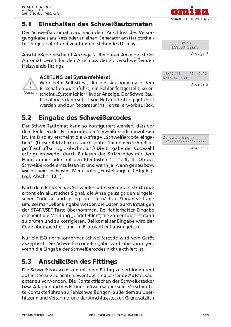
Version Februar 2020 DE 9Bedienungsanleitung HST 300 Smart
O.M. I . S .A . S r lVia Verga 9/1120845 Sovico (MB), Italien
5.1 Einschalten des SchweißautomatenDer Schweißautomat wird nach dem Anschluss des Versor-gungskabels ans Netz oder an einen Generator am Hauptschal-ter eingeschaltet und zeigt neben stehendes Display.
Anschließend erscheint Anzeige 2. Bei dieser Anzeige ist der Automat bereit für den Anschluss des zu verschweißenden Heizwendelfittings.
Vorsicht
ACHTUNG bei Systemfehlern! Wird beim Selbsttest, den der Automat nach dem
Einschalten durchführt, ein Fehler festgestellt, so er-scheint „Systemfehler“ in der Anzeige. Der Schweißau-tomat muss dann sofort von Netz und Fitting getrennt werden und zur Reparatur ins Herstellerwerk zurück.
5.2 Eingabe des SchweißercodesDerSchweißautomatkannsokonfiguriertwerden,dassvordem Einlesen des Fittingcodes der Schweißercode einzulesen ist. Im Display erscheint die Abfrage „Schweißercode einge-ben“. (Dieser Bildschirm ist auch später über einen Schnellzu-griff aufrufbar; vgl. Abschn. 6.1.) Die Eingabe der Codezahl erfolgt entweder durch Einlesen des Strichcodes mit dem Handscanner oder mit den Pfeiltasten ï, ð, ñ, ò. Ob der Schweißercode einzulesen ist und wenn ja, wann genau bzw. wie oft, wird im Einstell-Menü unter „Einstellungen“ festgelegt (vgl. Abschn. 10.1).
Nach dem Einlesen des Schweißercodes von einem Strichcode ertönt ein akustisches Signal, die Anzeige zeigt den eingele-senen Code an und springt auf die nächste Eingabeabfrage um. Bei manueller Eingabe werden die Daten durch Betätigen der START/SET-Taste übernommen. Bei fehlerhafter Eingabe erscheint die Meldung „Codefehler“; die Zahlenfolge ist dann zu prüfen und zu korrigieren. Bei korrekter Eingabe wird der Code abgespeichert und im Protokoll mit ausgegeben.
Nur ein ISO-normkonformer Schweißercode wird vom Gerät akzeptiert. Die Schweißercode-Eingabe wird übersprungen, wenn die Eingabe des Schweißercodes nicht aktiviert ist.
5.3 Anschließen des FittingsDie Schweißkontakte sind mit dem Fitting zu verbinden und auf festen Sitz zu achten. Eventuell sind passende Aufsteckad-apterzuverwenden.DieKontaktflächenderSchweißsteckerbzw. Adapter und des Fittings müssen sauber sein. Verschmutz-te Kontakte führen zu Fehlschweißungen, außerdem zu Über-hitzung und Verschmorung der Anschlussstecker. Grundsätzlich
Anzeige 1.
OMISA HST300 Smart
Anzeige 2.
14:32:11 21.10.12Kein Kontakt
Anzeige 3.
Schweissercode********************

Version Februar 202010 DE Bedienungsanleitung HST 300 Smart
O.M. I . S .A . S r lVia Verga 9/11
20845 Sovico (MB), Italien
sind Stecker vor Verschmutzung zu schützen. Kontakte und Aufsteckadapter sind Verschleißteile und müssen vor Gebrauch überprüft und bei Beschädigung oder Verschmutzung ausge-tauscht werden.
Nach dem Kontaktieren des Fittings erlischt die Meldung „Kein Kontakt“ (vgl. Anzeige 2) und die nächste Protokoll-Nr. wird angezeigt, z.B. „Prot.-Nr.: 0015“.
5.4 Einlesen des Fittingcodes mit einem HandscannerEs ist ausschließlich das auf dem angeschlossenen Fitting auf-geklebte Fittingcode-Etikett zu verwenden. Es ist unzulässig, ersatzweise das Fittingcode-Etikett eines andersartigen Fittings einzulesen.
Der Fittingcode wird eingelesen, indem der Scanner mit einer Entfernung von etwa 5 - 10 cm vor das Codeetikett gehalten wird; die rote Linie zeigt den Lesebereich an. Dann drücken Sie auf den Scanndruckknopf. Bei korrektem Erfassen der Daten gibt der Schweißautomat ein akustisches Signal und zeigt die decodierten Daten auf dem Display an (vgl. Anzeige 4).
Hinweis
Angezeigt werden die im Fittingcode enthaltenen bzw.
aus ihnen errechneten Soll-Daten für die Schweißung. Die Anzeige erfolgt im Übrigen vor der Messung des tatsächlichen Fittingwiderstands. Auch wenn der angezeigte Ohm-Wert in Ordnung ist, kann es daher noch zu einem Widerstandsfehler kommen (vgl. Ab-schn. 9.2). Erst mit Beginn der Schweißung werden deren Ist-Daten angezeigt.
Die Anzeige „Start ?“ signalisiert die Bereitschaft des Schweiß-automaten, den Schweißvorgang zu starten. Die eingelesenen Daten sind zu prüfen und können bei Fehlbedienung mit der STOP/RESET-Taste gelöscht werden. Ebenso werden die einge-lesenen Daten gelöscht, wenn die Verbindung des Schweißau-tomaten mit dem Fitting unterbrochen wird.
5.5 Starten des Schweißvorgangs
Hinweis
Nach dem Einlesen des Fittingcodes bzw. der Wahl der AutoWeld-Funktion werden zunächst alle Rückver-folgbarkeitsdaten abgefragt, deren Protokollierung im Einstell-Menü eingeschaltet ist (vgl. Abschn. 10.2).
Nach Einlesen oder Eingabe des Fittingcodes kann der Schweiß-vorgang mit der START/SET-Taste gestartet werden, wenn im Display „Start ?“ erscheint und keine Störung angezeigt wird.
Anzeige 4.
Start?HST SAT 10.00V 0130s
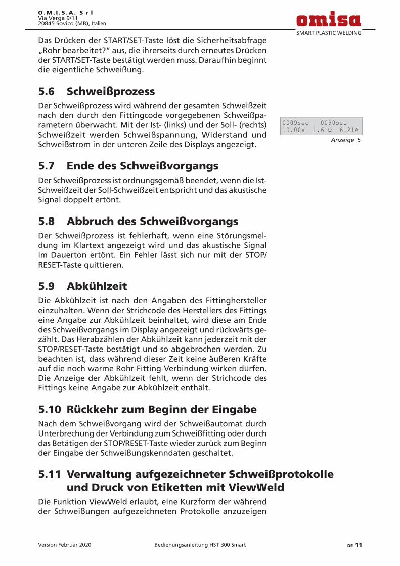
Version Februar 2020 DE 11Bedienungsanleitung HST 300 Smart
O.M. I . S .A . S r lVia Verga 9/1120845 Sovico (MB), Italien
Das Drücken der START/SET-Taste löst die Sicherheitsabfrage „Rohr bearbeitet?“ aus, die ihrerseits durch erneutes Drücken der START/SET-Taste bestätigt werden muss. Daraufhin beginnt die eigentliche Schweißung.
5.6 SchweißprozessDer Schweißprozess wird während der gesamten Schweißzeit nach den durch den Fittingcode vorgegebenen Schweißpa-rametern überwacht. Mit der Ist- (links) und der Soll- (rechts) Schweißzeit werden Schweißspannung, Widerstand und Schweißstrom in der unteren Zeile des Displays angezeigt.
5.7 Ende des SchweißvorgangsDer Schweißprozess ist ordnungsgemäß beendet, wenn die Ist-Schweißzeit der Soll-Schweißzeit entspricht und das akustische Signal doppelt ertönt.
5.8 Abbruch des SchweißvorgangsDer Schweißprozess ist fehlerhaft, wenn eine Störungsmel-dung im Klartext angezeigt wird und das akustische Signal im Dauerton ertönt. Ein Fehler lässt sich nur mit der STOP/RESET-Taste quittieren.
5.9 AbkühlzeitDie Abkühlzeit ist nach den Angaben des Fittinghersteller einzuhalten. Wenn der Strichcode des Herstellers des Fittings eine Angabe zur Abkühlzeit beinhaltet, wird diese am Ende des Schweißvorgangs im Display angezeigt und rückwärts ge-zählt. Das Herabzählen der Abkühlzeit kann jederzeit mit der STOP/RESET-Taste bestätigt und so abgebrochen werden. Zu beachten ist, dass während dieser Zeit keine äußeren Kräfte auf die noch warme Rohr-Fitting-Verbindung wirken dürfen. Die Anzeige der Abkühlzeit fehlt, wenn der Strichcode des Fittings keine Angabe zur Abkühlzeit enthält.
5.10 Rückkehr zum Beginn der EingabeNach dem Schweißvorgang wird der Schweißautomat durch UnterbrechungderVerbindungzumSchweißfittingoderdurchdas Betätigen der STOP/RESET-Taste wieder zurück zum Beginn der Eingabe der Schweißungskenndaten geschaltet.
5.11 Verwaltung aufgezeichneter Schweißprotokolle und Druck von Etiketten mit ViewWeld
Die Funktion ViewWeld erlaubt, eine Kurzform der während der Schweißungen aufgezeichneten Protokolle anzuzeigen
Anzeige 5.
0009sec 0090sec10.00V 1.61Ω 6.21A
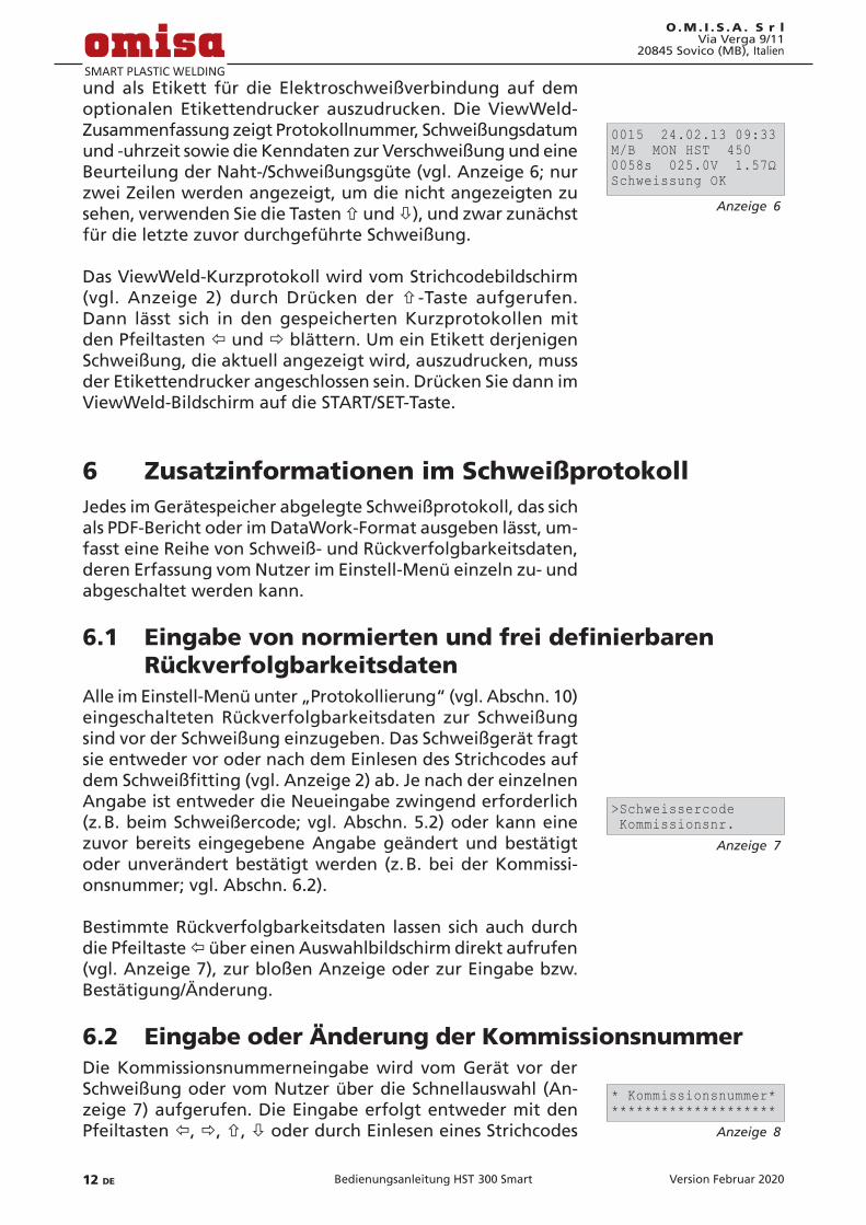
Version Februar 202012 DE Bedienungsanleitung HST 300 Smart
O.M. I . S .A . S r lVia Verga 9/11
20845 Sovico (MB), Italien
und als Etikett für die Elektroschweißverbindung auf dem optionalen Etikettendrucker auszudrucken. Die ViewWeld-Zusammenfassung zeigt Protokollnummer, Schweißungsdatum und -uhrzeit sowie die Kenndaten zur Verschweißung und eine Beurteilung der Naht-/Schweißungsgüte (vgl. Anzeige 6; nur zwei Zeilen werden angezeigt, um die nicht angezeigten zu sehen, verwenden Sie die Tasten ñ und ò), und zwar zunächst für die letzte zuvor durchgeführte Schweißung.
Das ViewWeld-Kurzprotokoll wird vom Strichcodebildschirm (vgl. Anzeige 2) durch Drücken der ñ -Taste aufgerufen. Dann lässt sich in den gespeicherten Kurzprotokollen mit den Pfeiltasten ï und ð blättern. Um ein Etikett derjenigen Schweißung, die aktuell angezeigt wird, auszudrucken, muss der Etikettendrucker angeschlossen sein. Drücken Sie dann im ViewWeld-Bildschirm auf die START/SET-Taste.
6 Zusatzinformationen im SchweißprotokollJedes im Gerätespeicher abgelegte Schweißprotokoll, das sich als PDF-Bericht oder im DataWork-Format ausgeben lässt, um-fasst eine Reihe von Schweiß- und Rückverfolgbarkeitsdaten, deren Erfassung vom Nutzer im Einstell-Menü einzeln zu- und abgeschaltet werden kann.
6.1 EingabevonnormiertenundfreidefinierbarenRückverfolgbarkeitsdaten
Alle im Einstell-Menü unter „Protokollierung“ (vgl. Abschn. 10) eingeschalteten Rückverfolgbarkeitsdaten zur Schweißung sind vor der Schweißung einzugeben. Das Schweißgerät fragt sie entweder vor oder nach dem Einlesen des Strichcodes auf demSchweißfitting(vgl.Anzeige2)ab.JenachdereinzelnenAngabe ist entweder die Neueingabe zwingend erforderlich (z. B. beim Schweißercode; vgl. Abschn. 5.2) oder kann eine zuvor bereits eingegebene Angabe geändert und bestätigt oder unverändert bestätigt werden (z. B. bei der Kommissi-onsnummer; vgl. Abschn. 6.2).
Bestimmte Rückverfolgbarkeitsdaten lassen sich auch durch die Pfeiltaste ï über einen Auswahlbildschirm direkt aufrufen (vgl. Anzeige 7), zur bloßen Anzeige oder zur Eingabe bzw. Bestätigung/Änderung.
6.2 Eingabe oder Änderung der KommissionsnummerDie Kommissionsnummerneingabe wird vom Gerät vor der Schweißung oder vom Nutzer über die Schnellauswahl (An-zeige 7) aufgerufen. Die Eingabe erfolgt entweder mit den Pfeiltasten ï, ð, ñ, ò oder durch Einlesen eines Strichcodes
Anzeige 6.
0015 24.02.13 09:33M/B MON HST 4500058s 025.0V 1.57ΩSchweissung OK
Anzeige 7.
>Schweissercode Kommissionsnr.
Anzeige 8.
* Kommissionsnummer*********************

Version Februar 2020 DE 13Bedienungsanleitung HST 300 Smart
O.M. I . S .A . S r lVia Verga 9/1120845 Sovico (MB), Italien
mit dem Scanner. Die maximale Länge beträgt 32 Stellen. Die Eingabe ist mit der START/SET-Taste zu bestätigen. Die Kom-missionsnummer wird abgespeichert und im Protokoll mit ausgegeben.
7 Manuelle Eingabe der VerschweißungsparameterZur manuellen Eingabe der Verschweißungsparameter ist zu-nächst der Fitting mit dem Schweißkabel zu kontaktieren. Die manuelle Eingabe kann dann mit der Pfeil-Taste ò aufgerufen werden, und es erscheint die in Anzeige 9 wiedergegebene Menüauswahl, vorausgesetzt die manuelle Eingabe ist im Einstell-Menü aktiviert (vgl. Abschn. 10.1). Mit anderen Worten erfolgt die manuelle Schweißkenndateneingabe anstelle des Einlesens des Fitting-Strichcodes mit einem Scanner.
Mit den Pfeil-Tasten ñ und ò kann zwischen „Eingabe Span-nung/Zeit“ und „Eingabe Fittingcode“ (d.h. die Zahlenfolge, diedenCodedes zu verwendendenElektroschweißfittingsrepräsentiert) gewählt werden. Mit START/SET ist die Auswahl zu bestätigen.
7.1 Manuelle Eingabe von Spannung und ZeitNach der entsprechenden Auswahl im Menü der manuellen Schweißparametereingabe erscheint das neben stehende Display. Mit den Pfeiltasten ï, ð, ñ, ò können hier die Schweißspannung und die Schweißzeit nach Angaben des Fitting-Herstellers vorgewählt und mit der START/SET-Taste bestätigt werden. Die Anzeige „Start ?“, die nach der Bestä-tigung mit der START/SET-Taste wieder erscheint, signalisiert die Schweißbereitschaft.
7.2 Eingabe ZahlenfolgeNach der entsprechenden Auswahl im Menü der manuellen Schweißparametereingabe erscheint im Display „Fittingcode eingeben“. Die 24 Stellen des Fittingcodes, der nun manuell einzugeben ist, sind als Asterisken ( * ) dargestellt. Die Einga-be geschieht mit den Pfeiltasten ï, ð, ñ, ò und wird mit der START/SET-Taste bestätigt und decodiert. Bei einer falschen Eingabe erscheint die Meldung „Eingabefehler“ und die Zah-lenfolge ist zu prüfen und zu korrigieren. Bei korrekter Eingabe werden die decodierten Daten angezeigt und die Anzeige „Start ?“ zeigt die Bereitschaft des Geräts.
8 Ausgabe der ProtokolleSchnittstelle
Anzeige 9.
>Eing. Spannung/Zeit Eing. Fittingcode
Anzeige 10.
Spannung/ZeitU= 40 V t= 1000 s

Version Februar 202014 DE Bedienungsanleitung HST 300 Smart
O.M. I . S .A . S r lVia Verga 9/11
20845 Sovico (MB), Italien
USB A-Schnittstelle für den Anschluss von USB-Speichermedien (z.B. USB-Stick)
DieSchnittstelleentsprichtderUSBVersion2.0-Spezifikation(d.h. maximale Datenrate von 480 Megabit pro Sekunde).
Wichtig
Vor dem Übertragen von Schweißdaten sollten Sie den Schweißautomaten aus- und wieder einschalten. Geschieht dies nicht, kann es zu fehlerhafter Daten-übertragung kommen und die Protokolle im Schweiß-automaten können unlesbar werden.
Wichtig
Wenn Sie Schweißprotokolle an einen USB-Stick aus-geben, warten Sie stets bis die Meldung „Ausgabe be-endet“ auf dem Display des Produkts erscheint, bevor Sie die Verbindung zum USB-Stick trennen. Trennen Sie die Verbindung vorher, kann es vorkommen, dass das Schweißgerät Ihnen das Löschen der Protokolle im Speicher anbietet, obwohl sie nicht ordnungsgemäß übertragen wurden. Falls Sie dann den Speicherinhalt löschen,gehendieProtokolleunwiderruflichverloren,obwohl sie nirgendwo sonst gespeichert sind.
8.1 Wahl des DateiformatsNach Anschließen des Speichermediums erscheint der Bild-schirm zur Auswahl des Formats, in dem die Daten ausgege-ben werden: PDF-Datei mit Kurz- oder Langbericht, Datei im Schweißungsdatenbankformat DataWork oder CSV-Datei. Mit den Pfeiltasten ñ und ò kann das Gewünschte gewählt wer-den. Die Wahl muss mit der START/SET-Taste bestätigt werden.
Das Format CSV erlaubt den Import der Protokolldaten in Datenbank- oder Kalkulationsanwendungen, wenn diese Anwendungen das Format lesen können; bei Microsoft Excel z.B. ist das so.
Die Option eines Service-Protokolls ist für den Normalbetrieb ohne Belang. Dieser Bericht gibt im Rahmen der computerge-stützten Gerätewartung Auskunft über die Ereignisse, die mit der Instandhaltung des Geräts zu tun haben.
8.2 Ausgabe aller ProtokolleNach der Wahl des Dateiformats kann im nächsten Bildschirm die Option „Alle Protokolle drucken“ gewählt werden. Da-durchwerdenalle imProtokollspeicherbefindlichenDatenim zuvor gewählten Format ausgegeben.
Anzeige 11.
DataWork-Datei >PDF-Kurzprotokoll

Version Februar 2020 DE 15Bedienungsanleitung HST 300 Smart
O.M. I . S .A . S r lVia Verga 9/1120845 Sovico (MB), Italien
8.3 Ausgabe von Kommissionsnummer, Datums- oder Protokollbereich
Nach der Wahl des Dateiformats können im nächsten Bild-schirm die Optionen „Nach Kommissionsnummer“, „Nach Da-tumsbereich“ und „Nach Protokollbereich“ gewählt werden. Je nach Auswahl kann dann mit den Pfeiltasten ñ und ò aus der Liste aller gespeicherten Kommissionen die gewünschte, deren Protokolle ausgegeben werden sollen, ausgewählt werden, oder es kann mit den Pfeiltasten ï, ð, ñ, ò eines Anfangs- und Enddatums bzw. des ersten und letzten Proto-kolls ein Datums- bzw. ein Protokollbereich bestimmt werden, dessen Protokolle ausgegeben werden sollen. Durch Drücken der START/SET-Taste wird die Ausgabe der ausgewählten Pro-tokolle Speichermedium gestartet.
8.4 Ablauf der ProtokollausgabeNach der Auswahl unter den Optionen wird der Ausgabevor-gang automatisch gestartet. Warten Sie, bis die gewählten Protokolle übertragen sind und am Bildschirm der Hinweis „Ausgabe beendet“ erscheint.
Sollte während der Ausgabe ein Problem entstehen, erscheint die Fehlermeldung „Nicht bereit“. Nach Beseitigung des Pro-blems wird die Ausgabe automatisch wieder aufgenommen.
Hinweis
Falls während der Übertragung der Schweißdaten ein Problem auftritt, das sich nicht beheben lässt, nimmt das Schweißgerät den die Ausgabe nicht wieder auf und zeigt die Fehlermeldung „Ausgabe abgebrochen“ an. Diese Meldung ist durch Drücken auf die Taste START/SET zu quittieren.
8.5 Löschen des SpeicherinhaltsDer Speicherinhalt kann erst nach der Ausgabe aller Proto-kolle gelöscht werden. Dies wird mit dem Hinweis „Ausgabe beendet“ angezeigt. Nach dem Entfernen des Speicher-Sticks kommt die Abfrage „Protokolle löschen“. Bei Bestätigung mit der START/SET-Taste erscheint die Sicherheitsabfrage „Proto-kolle wirklich löschen“, die nochmals mit der START/SET-Taste bestätigt werden muss. Daraufhin wird der Speicherinhalt gelöscht.
8.6 Erhalt des SpeicherinhaltsNach dem Entfernen des Kabels oder Sticks kommt die Abfra-ge „Speicher löschen“. Durch Drücken der STOP/RESET-Taste wird der Speicherinhalt erhalten und der Druckvorgang kann nochmals wiederholt werden.
Version Februar 202016 DE Bedienungsanleitung HST 300 Smart
O.M. I . S .A . S r lVia Verga 9/11
20845 Sovico (MB), Italien
Wichtig
Beachten SIe unbedingt die Hinweise eingangs von Abschn. 8 zur Datenintegrität, um das versehentliche Löschen der Protokolle im Speicher zu vermeiden.
9 GerätespezifischeInformationen
9.1 Anzeige der GerätekenndatenDie Kenndaten zum Schweißautomaten werden angezeigt, wenn bei der Anzeige „Strichcode-Eingabe“ die Taste ð gedrückt wird. Es handelt sich um die Softwareversion, die Seriennummer des Geräts, das Datum der nächsten fälligen Wartung und die Anzahl der derzeit nicht belegten Protokolle im Speicher. Mit der STOP/RESET-Taste kann die Anzeige wieder geschlossen werden.
Ist das empfohlene Wartungsdatum überschritten, erscheint beim Anschließen ans Netz oder den Generator ein Wartung-fällig-Hinweis auf dem Display und muss mit der START/SET-Taste quittiert werden.
9.2 WiderstandsmessungNach Betätigen der START/SET-Taste am Beginn einer Schwei-ßung wird der Fitting-Widerstand gemessen und mit den eingelesenen Werten des Fittingcodes verglichen. Ist die Abweichung zwischen beiden Werten kleiner als die im Code benannte Toleranz, beginnt der Schweißvorgang. Ist die Abweichung größer als die Toleranzvorgabe, stoppt der Schweißautomat mit der Meldung „Widerstandsfehler“. Zu-sätzlich erscheint in der Anzeige der gemessene Ist-Wert für den Fitting-Widerstand.
Ein Widerstandsfehler kann durch schlecht sitzende und/oder verschlissene Anschlusskontakte hervorgerufen werden. Daher sind diese bei Auftreten der Fehlermeldung zu püfen und, falls verschlissen, gegen neue zu ersetzen.
9.3 Thermischer ÜberlastschutzEine zu hohe Trafo-Temperatur im Schweißautomaten führt zum Schweißabbruch. Der Überwachungsschalter für die Tem-peratur des Transformators bricht bei einem zu hohen Tem-peraturwert die Schweißung ab, wenn die noch verbleibende Schweißzeit größer als 800 Sekunden ist. Im Display und im Protokoll erscheint die Meldung „Gerät zu heiß“.

Version Februar 2020 DE 17Bedienungsanleitung HST 300 Smart
O.M. I . S .A . S r lVia Verga 9/1120845 Sovico (MB), Italien
9.4 Hinweis auf Netzunterbrechung bei der letzten Schweißung
Der Hinweis „Netzunterbrechung letzte Schweißung“ zeigt an, dass der vorangegangene Schweißvorgang durch einen Netzausfall unterbrochen wurde. Die Ursache kann ein zu schwacher Generator oder ein zu langes oder zu dünnes Ver-längerungskabel sein. Oder aber der Sicherungsautomat des Schweißautomaten hat ausgelöst. Ein neuer Schweißvorgang ist dennoch möglich. Dazu ist zunächst die Störung mit der STOP/RESET-Taste zu quittieren.
10 KonfigurationdesSchweißautomatenDer Schweißautomat kann mittels Operator-Ausweis neu kon-figuriertwerden.NachBetätigenderMENÜ-TasteerscheintdieAbfrage „Menücode eingeben“. Nach dem Einlesen des Codes erscheint das in Anzeige 12 wiedergegebene Auswahlmenü.
Unter „Einstellungen“ lassen sich die Einstellungen zum Gerät selbstundseinemBetriebdefinieren.Unter„Protokollierung“werden die Rückverfolgbarkeitsdaten ein- oder ausgeschaltet, die in den Schweißprotokollen erscheinen oder nicht erschei-nen sollen. Die Auswahl geschieht mit den Pfeiltasten ñ und ò. Um das jeweilige Untermenü aufzurufen, ist dann die MENÜ-Taste zu drücken.
Mit den Pfeiltasten ñ und ò wird in beiden Teilen des Einstell-MenüsdergewünschteKonfigurationspunktgewählt.MitderPfeiltaste ðwirddiegewählteKonfigurationseinstellungvon„ein“ auf „aus“ geschaltet und umgekehrt.
StehtbeieinerKonfigurationseinstellungein„M“, sokanndurch Drücken der MENÜ-Taste ein Untermenü aufgerufen werden.
MitderSTART/SET-TastewirddieeingestellteKonfigurationbestätigt und abgespeichert.
10.1 Erläuterungen zum Untermenü „Einstellungen“„Schweißercode prüfen ein“ bedeutet, dass der Schweißer-
code noch gültig, nicht ausgelaufen sein muss (normale Gültigkeitsdauer 2 Jahre ab Kartenausgabe) und sonst das Schweißen nicht gestartet werden kann, „aus“, dass die Gültigkeit des Codes nicht überprüft wird.
„Speicher-Kontrolle ein“ bedeutet, dass bei vollem Proto-kollspeicher der Schweißautomat blockiert ist, bis die Protokolle ausgedruckt oder übertragen werden, „aus“, dass er nicht blockiert ist und das älteste Protokoll über-schrieben wird.
Anzeige 12.
>Einstellungen -M- Protokollierung -M-
Anzeige 13.
>Schw.Code prüf. aus Speicher-Kontr. ein
Version Februar 202018 DE Bedienungsanleitung HST 300 Smart
O.M. I . S .A . S r lVia Verga 9/11
20845 Sovico (MB), Italien
„Manuelle Eingabe ein“ bedeutet, dass die manuelle Eingabe der Verschweißungskenndaten (vgl. Abschn. 7) möglich ist, „aus“, dass diese Eingabe nicht verfügbar ist.
„Schweißercode-Optionen – M – “ bedeutet, dass durch Be-tätigen der MENÜ-Taste das Untermenü aufgerufen wird, in dem bestimmt wird, wie oft der Schweißercode, wenn er unter „Protokollierung“ eingeschaltet ist, eingegeben werden muss: immer, d. h. vor jeder Schweißung, nur nach Einschalten des Geräts oder nur bei der ersten Schweißung eines neuen Tags/Datums.
„Sprache – M – “ bedeutet, dass durch Betätigen der MENÜ-Taste das Untermenü zum Auswählen der Bedienersprache aufgerufen wird (vgl. Abschn. 10.1.1).
„Datum/Uhrzeit – M – “ bedeutet, dass durch Betätigen der MENÜ-Taste das Untermenü zum Stellen der Uhr aufge-rufen wird (vgl. Abschn. 10.1.2).
„Temperatureinheit – M – “ bedeutet, dass durch Betätigen der MENÜ-Taste das Untermenü zur Wahl von Celsius oder Fahrenheit als Temperatureinheit aufgerufen wird.
„Inventarnummer – M – “ bedeutet, dass durch Betätigen der MENÜ-Taste das Untermenü zur Eingabe der Nummer, unterderdasGerätbeiderBetreiberfirmainterninven-tarisiert ist, aufgerufen wird.
„Anzahl Etiketten – M – “ bedeutet, dass durch Betätigen der MENÜ-Taste das Untermenü zur Eingabe der Anzahl Etiket-ten aufgerufen wird, die nach einer Schweißung Etiketten automatisch über den optionalen Etikettendrucker ausge-geben werden sollen, falls ein solcher angeschlossen ist.
10.1.1 Wahl der Anzeige-SpracheNach Wahl des Untermenüs „Sprache wählen“ erscheint das in Anzeige 14 wiedergegebene Display.
Mit den Pfeiltasten ñ und ò wird zwischen „Deutsch“, „Eng-lish“, und „Français“ gewählt und mit der START/SET-Taste die Auswahl bestätigt.
10.1.2 Stellen von Datum und UhrzeitNach Wahl des Untermenüs „Uhr einstellen“ erscheint das in Anzeige 15 wiedergegebene Display.
Uhrzeit und Datum können unter Verwendung der Tastatur geändert werden. Dabei werden die Abschnitte „Stunde“, „Minute“, „Tag“, „Monat“ und „Jahr“ je einzeln eingestellt. Mit der START/SET-Taste werden die Einstellungen bestätigt.
10.1.3 Wahl der TemperatureinheitDie Einheit für Temperaturangaben (Celsius oder Fahrenheit)
Anzeige 14.
>Deutsch English
Anzeige 15.
Datum/Uhrzeit1.06.13 14:28

Version Februar 2020 DE 19Bedienungsanleitung HST 300 Smart
O.M. I . S .A . S r lVia Verga 9/1120845 Sovico (MB), Italien
lässt sich in einem Untermenü gleich dem für die Sprachwahl (vgl. Abschn. 10.1.1) auswählen.
10.2 Erläuterungen zum Untermenü „Protokollierung“„Schweißercode ein“ bedeutet, dass je nach Einstellung unter
„Schweißercode-Optionen“ der Schweißercode eingelesen werden muss, „aus“, dass das nicht möglich ist.
„Kommissionsnummer ein“ bedeutet, dass vor jeder Schwei-ßung die Kommissionsnummer neu eingegeben oder be-stätigt werden muss, „aus“, dass sie nicht abgefragt wird.
„Zusatzdaten ein“ bedeutet, dass vor jeder Schweißung die Zusatzdaten neu eingegeben werden müssen, „aus“, dass sie nicht abgefragt werden.
„Formteilcode ein“ bedeutet, dass vor jeder Schweißung der zweite, sogenannte Rückverfolgbarkeitscode des Elektro-schweißfittingseingegebenwerdenmuss, „aus“, dass das nicht möglich ist.
„Rohrcodes ein“ bedeutet, dass vor jeder Schweißung die Codes beider Rohre/Werkstücke (ISO-Schweiß- und Rück-verfolgbarkeitscodes) eingegeben werden müssen, „aus“, dass das nicht möglich ist.
„Rohrlänge ein“ bedeutet, dass vor jeder Schweißung die Länge beider Rohre/Werkstücke eingegeben werden muss, „aus“, dass das nicht möglich ist.
„Witterung ein“ bedeutet, dass vor jeder Schweißung die Witterungsbedingungen in einer Liste gewählt werden müssen, „aus“, dass das nicht möglich ist.
„Verlegefirmaein“bedeutet,dassvorjederSchweißungdieFirma, die die Arbeiten durchführt, eingegeben werden muss, „aus“, dass das nicht möglich ist.
„Etiketten drucken – M – “ bedeutet, dass durch Betätigen der MENÜ-Taste das Untermenü zum Ausdruck eines/meh-rerer Etikett(en) zu einer Schweißung mit dem optionalen Etikettendrucker aufgerufen wird.
Hinweis
Alle Daten können auch mit dem Scanner von einem Strichcode eingelesen werden, falls ein solcher Code vorhanden ist.
11 AuflistungderÜberwachungsfunktionen
11.1 Fehlerarten während der Eingabe
11.1.1 CodefehlerEs liegt eine falsche Eingabe, ein Fehler am Codeträ-ger, im Codeaufbau oder unsachgemäßes Einlesen vor.
Anzeige 16.
Schweissercode ein>Kommissionsnr. ein

Version Februar 202020 DE Bedienungsanleitung HST 300 Smart
O.M. I . S .A . S r lVia Verga 9/11
20845 Sovico (MB), Italien
11.1.2 Kein KontaktEs besteht keine vollständige elektrische Verbindung zwischen dem Schweißautomaten und dem Fitting (Steckverbindung zum Fitting überprüfen) bzw. eine Unterbrechung im Heiz-wendel.
11.1.3 UnterspannungDie Eingangsspannung ist kleiner als 175 Volt. Generator-Ausgangsspannung nachregeln.
11.1.4 ÜberspannungDie Eingangsspannung ist größer als 290 Volt. Generator-Ausgangsspannung herunterregeln.
11.1.5 Gerät zu heißDie Temperatur des Transformators ist zu hoch. Den Schweiß-automaten ca. 1 Stunde abkühlen lassen.
11.1.6 SystemfehlerACHTUNG!Der Schweißautomat muss sofort von Netz und Fitting getrennt werden. Der Selbsttest hat Fehler im System gefunden. Der Schweißautomat darf nicht mehr verwendet werden und muss zur Reparatur eingeschickt werden.
11.1.7 TemperaturfehlerGemessene Umgebungstemperatur ist außerhalb des Arbeits-bereiches des Gerätes, niedriger als – 20°C (– 4°F) oder höher als + 60°C (+ 140°F).
11.1.8 Temperaturmessung defektDer Temperatur-Außenfühler am Schweißkabel ist beschädigt oder defekt.
11.1.9 Uhr defektDie interne Uhr ist gestört oder defekt. Bitte die Uhr neu ein-stellen. Sonst den Schweißautomaten ins Werk zur Wartung und Überprüfung einsenden.
11.1.10 Gerät zur WartungDer empfohlene Wartungstermin des Schweißautomaten ist überschritten. Die Meldung „Wartung fällig“ muss mit der START/SET-Taste quittiert werden. Den Schweißautomaten ins Werk oder zu einer autorisierten Servicestelle zur Wartung und Überprüfung einsenden.

Version Februar 2020 DE 21Bedienungsanleitung HST 300 Smart
O.M. I . S .A . S r lVia Verga 9/1120845 Sovico (MB), Italien
11.1.11 EingabefehlerEin Code wurde falsch eingegeben. Es wurde bei der manuellen Schweißparametereingabe keine Schweißzeit vorgewählt. In der Datumseinstellung wurde ein ungültiger Bereich vorge-wählt.
11.1.12 Protokollspeicher vollDer Protokollspeicher ist voll. Die Schweißprotokolle ausgeben oder die Speicherkontrolle ausschalten. Bei ausgeschalteter Speicherkontrolle überschreibt ein neues Protokoll das älteste vorhandene.
11.1.13 Ausgabe abgebrochenWährend des Audrucks oder der Übertragung von Schweiß-daten ist ein Fehler aufgetreten, der nicht behoben werden konnte.
11.2 Fehlerarten während des SchweißvorgangsAlle Fehler, die während des Schweißvorgangs auftreten, wer-den mit einem akustischen Signal gemeldet.
11.2.1 UnterspannungDie Eingangsspannung ist kleiner als 175 Volt. Steht der Fehler länger als 15 Sekunden an, wird der Schweißvorgang abgebrochen. Sinkt die Spannung unter 170 Volt, so wird der Schweißvorgang sofort abgebrochen.
11.2.2 ÜberspannungDie Eingangsspannung ist größer als 290 Volt. Steht der Fehler länger als 15 Sekunden an, wird der Schweißvorgang abge-brochen.
11.2.3 WiderstandsfehlerDerWiderstandswertdes angeschlossenen Schweißfittingsliegt außerhalb der eingelesenen Toleranz.
11.2.4 FrequenzfehlerDie Frequenz der Eingangsspannung liegt nicht innerhalb der Toleranz (42 Hz - 69 Hz).
11.2.5 SpannungsfehlerGeneratorspannung und -leistung überprüfen. Die Aus-gangsspannung entspricht nicht dem eingelesenen Wert; der Schweißautomat muss zur Überprüfung ins Werk.
Version Februar 202022 DE Bedienungsanleitung HST 300 Smart
O.M. I . S .A . S r lVia Verga 9/11
20845 Sovico (MB), Italien
11.2.6 Strom zu niedrigDiese Meldung erscheint bei momentaner Unterbrechung des StromflussesoderwennderStromflussin3Sekundenummehrals 15 % pro Sekunde absinkt.
11.2.7 Strom zu hochDer Wert des Ausgangsstromes ist zu groß; Fehlerquellen: Kurzschluss im Heizwendel oder in der Schweißleitung. Wäh-rend der Anlaufphase beträgt der obere Abschaltwert das 1,18-fache des Anfangswertes, ansonsten ist die Obergrenze lastabhängig und liegt 15 % über dem Anlaufstrom.
11.2.8 Not-AusDer Schweißvorgang wurde mit der STOP/RESET- Taste unter-brochen.
11.2.9 WindungsschlussDer Stromverlauf weicht während der Schweißung um 15 % vom Sollwert ab, bedingt durch Kurzschluss im Heizwendel.
11.2.10 Netzunterbrechung bei der letzten SchweißungDie vorherige Schweißung ist unvollständig. Der Schweiß-automat wurde während ihr von der Versorgungsspannung getrennt. Um weiter arbeiten zu können, muss die Meldung durch Drücken der STOP/RESET-Taste quittiert werden (vgl. auch Abschn. 9.4).
12 Datenblatt des ProduktsArbeitsbereich Fittinge bis 160 mmNennspannung 230 VFrequenz 50 Hz/60 HzLeistung 1680 VA, 80 % EDSchutzart IPX4Strom primär max. 16 AUmgebungstemperatur – 20°C bis + 60°C (– 4°F bis + 140°F)Ausgangsspannung 8 V - 48 Vmax. Ausgangsstrom 65 AProtokollplätze 500 ProtokolleÜbetragungsschnittstelle USB v 2.0 (480 mbit/s) (vgl. auch die Angaben zu den Schnittstellen anfangs Abschn. 8)
Messtoleranzen: Temperatur ± 5 % Spannung ± 2 % Strom ± 2 % Widerstand ± 5 %

Version Februar 2020 DE 23Bedienungsanleitung HST 300 Smart
O.M. I . S .A . S r lVia Verga 9/1120845 Sovico (MB), Italien
13 Anschrift für Wartung und Reparatur O.M.I.S.A. S r l Via Verga 9/11 Tel.: +39 039 23 23 028 20845 Sovico (MB), Italien
Web: www.omisa.it Mail: [email protected]
Hinweis
Technische Änderungen am Produkt bleiben vorbehalten.
14 Zubehör/Ersatzteile für das ProduktWinkel Aufsteck-Adapter 4,0 - 4,7 90° 216 - 010 - 440Adapter-Tasche 216 - 030 - 310Lesestift 216 - 030 - 270USB-Kabel 300 - 010 - 167Schweißer-/Operatorausweis 216 - 080 - 031Software DataWork für Windows 216 - 080 - 505USB-Stick 300 - 010 - 154

La versione tedesca qui inclusa è il testo originale del manuale, dal quale vennero elaborate le incluse traduzioni.The German version of the manual enclosed herein is the original copy, reflected in the translations herein.Inliegende deutsche Fassung der Anleitung ist der Urtext, welchen inliegende Übersetzungen wiedergeben.
La versión alemana adjunta está el texto original de las instrucciones, que también representan las traducciones de esta.
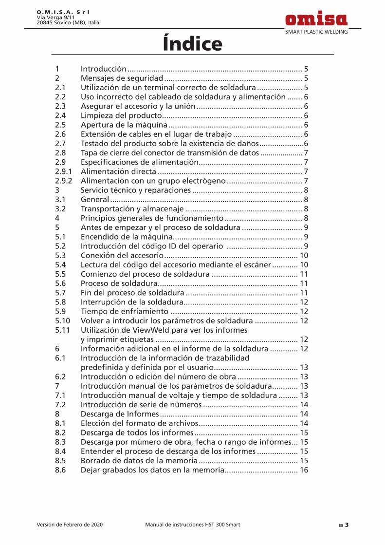
Versión de Febrero de 2020 ES 3Manual de instrucciones HST 300 Smart
O.M. I . S .A . S r lVia Verga 9/1120845 Sovico (MB), Italia
Índice1 Introducción ................................................................................. 52 Mensajes de seguridad ................................................................ 52.1 Utilización de un terminal correcto de soldadura ..................... 52.2 Uso incorrecto del cableado de soldadura y alimentación ....... 62.3 Asegurar el accesorio y la unión ................................................. 62.4 Limpieza del producto ................................................................. 62.5 Apertura de la máquina .............................................................. 62.6 Extensión de cables en el lugar de trabajo ................................ 62.7 Testado del producto sobre la existencia de daños .....................62.8 Tapa de cierre del conector de transmisión de datos ..................... 72.9 Especificacionesdealimentación ................................................ 72.9.1 Alimentación directa ................................................................... 72.9.2 Alimentación con un grupo electrógeno ................................... 73 Servicio técnico y reparaciones ................................................... 83.1 General ......................................................................................... 83.2 Transportación y almacenaje ...................................................... 84 Principios generales de funcionamiento .................................... 85 Antes de empezar y el proceso de soldadura ............................ 95.1 Encendido de la máquina ............................................................ 95.2 Introducción del código ID del operario ................................... 95.3 Conexión del accesorio .............................................................. 105.4 Lectura del código del accesorio mediante el escáner ............ 105.5 Comienzo del proceso de soldadura ........................................ 115.6 Proceso de soldadura ................................................................. 115.7 Fin del proceso de soldadura .................................................... 115.8 Interrupción de la soldadura ..................................................... 125.9 Tiempo de enfriamiento ........................................................... 125.10 Volver a introducir los parámetros de soldadura .................... 125.11 Utilización de ViewWeld para ver los informes y imprimir etiquetas .................................................................. 126 Información adicional en el informe de la soldadura ............. 126.1 Introducción de la información de trazabilidad predefinidaydefinidaporelusuario ....................................... 136.2 Introducción o edición del número de obra ............................ 137 Introducción manual de los parámetros de soldadura ............ 137.1 Introducción manual de voltaje y tiempo de soldadura ......... 137.2 Introducción de serie de números ............................................ 148 Descarga de Informes ................................................................ 148.1 Elección del formato de archivos .............................................. 148.2 Descarga de todos los informes ................................................ 158.3 Descarga por múmero de obra, fecha o rango de informes ... 158.4 Entender el proceso de descarga de los informes ................... 158.5 Borrado de datos de la memoria .............................................. 158.6 Dejar grabados los datos en la memoria .................................. 16

Versión de Febrero de 20204 ES Manual de instrucciones HST 300 Smart
O.M. I . S .A . S r lVia Verga 9/11
20845 Sovico (MB), Italia
9 Información detallada de la máquina ...................................... 169.1 Características de la máquina en la pantalla ........................... 169.2 Medición de resistencia ............................................................. 169.3 Interruptor de sobrecalentamiento .......................................... 179.4 Indicación de fallo de alimentación en la última soldadura realizada .............................................. 1710 Configuracióndelamáquina ................................................... 1710.1 Entender el sub-menú “Ajustes” .............................................. 1810.1.1 Selección del idioma de la pantalla .......................................... 1810.1.2 Ajustar el reloj ............................................................................ 1910.1.3 Ajustes del volumen de la bocina ............................................. 1910.1.4 Selección de la unidad de temperatura ................................... 1910.2 Entender el sub-menú “Guardando” ....................................... 1911 Resumen de errores auto-ajustables ........................................ 1911.1 Errores durante la introducción de datos ................................ 1911.1.1 Error código ............................................................................... 1911.1.2 Sin contacto ................................................................................ 2011.1.3 Subtensión .................................................................................. 2011.1.4 Sobretensión .............................................................................. 2011.1.5 Unidad sobrecalentada ............................................................. 2011.1.6 Error de sistema ......................................................................... 2011.1.7 Error temperatura ...................................................................... 2011.1.8 Fallo sensor de temperatura ..................................................... 2011.1.9 Fallo en reloj .............................................................................. 2011.1.10 Unidad al SAT ............................................................................. 2011.1.11 Error de entrada ........................................................................ 2111.1.12 Memoria protocolos llena ......................................................... 2111.1.13 Descarga cancelada ................................................................... 2111.2 Errores durante el ciclo de soldadura ....................................... 2111.2.1 Subtensión .................................................................................. 2111.2.2 Sobretensión .............................................................................. 2111.2.3 Error resistencia ......................................................................... 2111.2.4 Error frecuencia ......................................................................... 2111.2.5 Error tensión .............................................................................. 2111.2.6 Corriente baja ............................................................................ 2211.2.7 Corriente alta ............................................................................. 2211.2.8 Parada de emergencia ............................................................... 2211.2.9 Error bobina ............................................................................... 2211.2.10 Interrupción alimentación última soldadura ........................... 2212 Especificacionestécnicas ........................................................... 2213 Contacto Servicio Técnico y reparación .................................... 2314 Accesorios/Recambios del producto ......................................... 23
Versión de Febrero de 2020 ES 5Manual de instrucciones HST 300 Smart
O.M. I . S .A . S r lVia Verga 9/1120845 Sovico (MB), Italia
1 IntroducciónEstimado Cliente:
Muchas gracias por adquirir nuestro producto. Estamos seguros que va a reunir todas sus expectativas.
La máquina de electrofusión HST 300 Smart está diseñada en exclusiva para soldar accesorios para tuberías plásticas de 160 mm diámetro máximo según la normativa del proceso de electrofusión.
Este producto fue desarrollado y fabricado de acuerdo con las últimas tecnologías y normativas de seguridad y está dotado de las últimas características de control de seguridad.
Antes de ser entregado al cliente, el producto fue revisado tanto en cuestión de seguridad como los procesos para los se destina. De todas formas, en caso de mal uso o incorrecta manipulación del producto el usuario está expuesto a los si-guientes tipos de peligro y fallos:• Lasaluddeloperario,• Otramaquinariainvolucradoenelproceso,• Funcionamientocorrectodelproducto.
Todo el personal involucrado en los procesos de la puesta en marcha, funcionamiento, mantenimiento y servicio técnico del producto debe:• Seradecuadamentecualificados,• Estarsiemprepresentesdurantelosprocesos,• LeerdetenidamenteesteManualdeInstruccionesantes
de empezar la utilización del producto.
Gracias.
2 Mensajes de seguridad
2.1 Utilización de un terminal correcto de soldaduraSe debe utilizar el terminal (conector) adecuado al accesorio que se va a utilizar para la soldadura. Se debe asegurar que seestableceuncontactofirmeentreelterminalyelaccesorioy no se deben utilizar los terminales o conectores quemados o no compatibles con el uso que se les va a dar.
2.2 Uso incorrecto del cableado de soldadura y alimentación
No se debe llevar el producto cogido por sus cables y no tire
Versión de Febrero de 20206 ES Manual de instrucciones HST 300 Smart
O.M. I . S .A . S r lVia Verga 9/11
20845 Sovico (MB), Italia
del cable para desenchufarlo. Protejan el cableado de calor excesivo,aceitesysuperficiescortantes.
2.3 Asegurar el accesorio y la uniónUtilice un alineador u otra herramienta para asegurar la posi-ción del accesorio antes de realizar una soldadura. Las instruc-ciones del fabricante del accesorio y las Normativas locales y nacionales se deben seguir en todo momento.
No se debe nunca repetir el proceso de soldadura con el mis-mo accesorio ya que podría provocar un cortocircuito de los elementos.
2.4 Limpieza del productoEste producto no puede ser rociado ni colocado bajo el agua.
2.5 Apertura de la máquina
Atención
La cubierta de la máquina puede ser retirada solo por personal especializado indicado por el fabricante o Ser-vicio Técnico, especialmente entrenado y autorizado.
2.6 Extensión de cables en el lugar de trabajoPara alargar el cable de alimentación principal en el lugar de trabajo es imprescindible la utilización solo del cableado ade-cuadamente aprobado para este tipo de maquinaria debiendo tener las siguientes secciones de conducción:hasta 20 m: 1,5 mm² (2,5 mm² recomendado); tipo H07RN-Fmás de 20 m: 2,5 mm² (4,0 mm² recomendado); tipo H07RN-F
Atención
Cuando se alarga el cable, tiene que estar siempre completamente desenrollado y colocado en la posición horizontal.
2.7 Testado del producto sobre la existencia de dañosAntes de empezar la utilización del producto se debe revisar detenidamente todas las partes de este para valorar la exis-tencia de cualquier menor daño visible para el correcto fun-cionamiento. Asegúrese de que los terminales de soldadura funcionan adecuadamente, se establece el contacto total con el accesorioyquetodaslassuperficiesencontactoestánlimpias.Todos los componentes deben ser instalados correctamente y acorde con las condiciones de trabajo. En caso de existir da-ños, deben ser reparados y revisados por un servicio técnico aprobado por el fabricante.

Versión de Febrero de 2020 ES 7Manual de instrucciones HST 300 Smart
O.M. I . S .A . S r lVia Verga 9/1120845 Sovico (MB), Italia
2.8 Especificacionesdealimentación
2.8.1 Alimentación directaSe deben respetar en todo momento los requerimientos del fabricante del cableado, normativa de seguridad, estándares nacionales y locales aplicables.
Atención
Al utilizar el cableado eléctrico en lugar de trabajo, se deben respetar las reglas de correcta instalación y se debe disponer de interruptores diferenciales de fuga a tierra; el funcionamiento de la máquina requiere la instalación del interruptor diferencial.
El generador o la instalación eléctrica directa deben ser máx. 16 A (fusible de fusión lenta). El producto se debe proteger de la lluvia y la humedad.
2.8.2 Alimentación con un grupo electrógenoLa capacidad nominal del generador es determinada por el ac-cesorio con el diámetro superior que se va a utilizar y depende asuvezdelasespecificacionesdelaalimentaciónsuministrada,condiciones meteorológicas y el tipo de generador incluidas sus características de control y regulación.
Potencia nominal de salida del generador monofásico, 220 - 240 V, 50/60 Hz: d 20 ..... d 160 3,2 kW
Primero se pone en marcha el generador y después se conecta la máquina. Se debe alcanzar el voltaje en ralentí de 240 vol-tios. Para apagar el generador, primero se debe apagar y des-conectar la máquina.
Importante
La potencia de salida del generador se disminuye aproximadamente un 10% cada 1.000 m de altura. Du-rante el proceso de soldadura está prohibido conectar cualquier otro dispositivo al mismo grupo electrógeno.
3 Servicio técnico y reparacionesAl ser este un producto con estrictos controles de seguridad, solo personal autorizado por el fabricante puede dar servicio técnico y reparaciones. De esta manera se mantienen constan-tementealtosestándaresdeseguridadyserviciocualificado.
En caso contrario el fabricante se exime de cualquier responsabilidad de garantía y reclamaciones sobre el producto incluido cualquier daño posterior.
Versión de Febrero de 20208 ES Manual de instrucciones HST 300 Smart
O.M. I . S .A . S r lVia Verga 9/11
20845 Sovico (MB), Italia
Al ser revisado / reparado el producto se actualiza según las especificacionestécnicasenelmomentodelarevisiónsedauna garantía de 3 meses sobre su funcionamiento.
Se recomienda la revisión anual del producto.
Observeimperativamentelasdisposicioneslegalesencuantoal control de seguridad eléctrica.
4 Principios generales de funcionamientoLa máquina HST 300 Smart permite la soldadura de accesorios de electrofusión que llevan un código de barras. Cada accesorio lleva una etiqueta donde se indica uno o dos códigos de barras. La estructura de este código está estandarizada internacional-mente. El primer código contiene la información de la propia uniónsegún laNormativa ISO13950,el segundocódigo, siexiste, contiene la información adicional de trazabilidad según laNormativaISO12176.
El microprocesador de la máquina HST 300 Smart:• Controlaymonitorizaelprocesodesoldaduradelama-
nera totalmente automática,• Determina laduraciónde soldaduradeacuerdo con la
temperatura del ambiente,• Muestratodalainformaciónenlapantallaenformatode
texto plano
Todos los datos relevantes de la soldadura o su trazabilidad se graban en la memoria interna y pueden ser guardados en una memoria USB.
El conector de la transmisión de datos es del tipo USB A com-patible con una memoria USB tipo “pen”.
Accesorios opcionales disponibles:• PC software para la descarga y archivo de datos en un
ordenador PC (para todos los principales entornos Win-dows)
• Impresora de etiquetasparaidentificarcadasoldadurajusto después de que termine el proceso de soldadura
• Memoria USB tipo “pen” para la transmisión de datos de la máquina que se encuentra en obra directamente a unaimpresoraounordenadorPCensuoficina(verdetallesalfinaldeestemanual)
5 Antes de empezar y el proceso de soldadura• Paraempezarlautilizacióndelproducto,sedebeasegurar
sucorrectaposiciónsobreunasuperficieplanaynivelada.

Versión de Febrero de 2020 ES 9Manual de instrucciones HST 300 Smart
O.M. I . S .A . S r lVia Verga 9/1120845 Sovico (MB), Italia
• Asegurarsequelaproteccióndelaalimentacióndirecta/grupo generador es de 16 A.
• Conectarelenchufedelcabledealimentaciónenelen-chufe de la red eléctrica/generador.
• Leerdetenidamenteelmanualdeinstruccionesdelgene-rador si procede.
5.1 Encendido de la máquinaDespués de conectar el cable de alimentación a la red eléctrica ogeneradorenciendalamáquinamedianteelinterruptorOn/Off.AparecelaPantalla1enlapantalla.
Después la pantalla muestra la Pantalla 2: En este pantalla la máquina está presta para la conexión del accesorio.
Atención
¡ATENCIÓN en caso de errores del sistema! Si durante el testado automático realizado por la má-
quina durante su encendido se detecta un error, apa-rece el mensaje de “Error del Sistema” en la pantalla. En este caso la máquina se debe desconectar inmedia-tamente tanto de alimentación como del accesorio y se debe enviar al fabricante / Servicio Técnico para su reparación.
5.2 Introducción del código ID del operario Lamáquinapuedeserconfiguradadetalmaneraquesiem-pre pregunte antes por el código ID de operario y luego por el código del accesorio. El mensaje que aparece en pantalla entonces es “Código soldador” (Luego este paso puede ser configuradosegúnpunto6.1parasurápidoacceso).Elcódigonumérico puede ser introducido también desde un código de barrasutilizandoelescánerolasteclasconflechaï, ð, ñ, ò. La obligación o no de introducción del código ID del operario ylafrecuenciadelaintroduccióndelcódigoseconfiguraenel menú “Ajustes” (ver punto 10.1).
Cuando el código del operario es introducido mediante la lec-tura del código de barras con el escáner, el sonido producido confirmalalectura,elcódigoapareceenlapantallaypasaalsiguiente paso. Cuando el código es introducido manualmen-tehayqueconfirmarlopresionandoelbotónSTART/SET.Siescódigo introducido no es correcto aparece el mensaje “Error Código” en la pantalla; revise la secuencia de números y corrija donde sea necesario. Si el código es correcto, será grabado en el sistema y aparecerá en los informes de las soldaduras realizadas.
La máquina solo acepta el código de operario según los están-daresISO.Enelcasodedeshabilitarlaintroduccióndelcódigodel operario, los mensajes no aparecerán.
Pantalla 1
OMISA HST300 Smart
Pantalla 2
14:32:11 21.10.12Sin contacto
Pantalla 3
Codigo soldador********************

Versión de Febrero de 202010 ES Manual de instrucciones HST 300 Smart
O.M. I . S .A . S r lVia Verga 9/11
20845 Sovico (MB), Italia
5.3 Conexión del accesorioConecte los terminales de soldadura con el accesorio y asegú-rese de que haga el contacto adecuado. Utilice los conectores siesnecesario.Lasuperficiedeconexionesdecablesdelosterminales o conectores y la del accesorio debe estar limpia. Los terminales sucios pueden provocar una soldadura incorrecta y el sobrecalentamiento y cortocircuito. Proteja los terminales y los conectores de la suciedad en todo momento. Tanto los terminales como los conectores de consideran consumibles, se deben revisar antes de cada soldadura para ser reemplazados en caso de estar sucios o dañados.
Al conectar el accesorio en vez del mensaje “Sin contacto” (Pantalla 2) aparece el número de la siguiente soldadura, por ej. “No. prot.: 0015”.
5.4 Lectura del código del accesorio mediante el escáner
Solo se debe utilizar el código de barras de soldadura de la eti-queta adhesiva sobre el accesorio. Está prohibido leer el código de la otra etiqueta del accesorio o de una del accesorio de otro tipo si el código del accesorio a soldar está dañado o ilegible.
Lea el código de barras colocando el escáner delante de este a una distancia de unos 5 a 10 cm, la línea roja indicará el área de lectura. Después pulse el botón de lectura. Si los datos están leídoscorrectamentelamáquinaloconfirmaráconunaseñalacústica y estos datos aparecerán en la pantalla (Pantalla 4).
Info
Los datos en la pantalla son los parámetros nominales contenidos en el código del accesorio o calculados basados en estos datos. Se muestran antes de que se midalaresistenciaactualdelaccesorio.EstosignificaqueaunquesemuestrequelosdatosohmestánOk,aún puede detectarse un error de resistencia (ver Pun-to 9.2). Solo cuando empieza el proceso de soldadura se muestra la información actual después de medición de todos los parámetros.
Elmensaje“Inicio?”significaquelamáquinaestápreparadapara el comienzo del proceso de soldadura. Revise la informa-ción en pantalla y si ve que es errónea bórrala presionando la teclaSTOP/RESET.Lainformacióntambiénpuedeserborradasi se desconecta el accesorio de la máquina.
5.5 Comienzo del proceso de soldadura
Info
Después de leer el código de barras o activar la opción AutoWeld el sistema requiere la introducción de toda

Versión de Febrero de 2020 ES 11Manual de instrucciones HST 300 Smart
O.M. I . S .A . S r lVia Verga 9/1120845 Sovico (MB), Italia
la información de trazabilidad habilitada en el menú “Ajustes” (ver Punto 10.2).
Después de leer o introducir el código del accesorio se puede comenzar el proceso de soldadura utilizando el botón START/SET cuando el mensaje “Inicio?” aparece en pantalla y no aparece ningún mensaje de error.
AlpresionarlateclaSTART/SETapareceráelmensajedeconfir-mación“Tuboacondicionado?”querequiereconfirmaciónpre-sionando otra vez la tecla START/SET para empezar el proceso.
5.6 Proceso de soldaduraEl proceso de soldadura es monitorizado en todo momento según los parámetros contenidos en el código del accesorio. Juntos al tiempo de soldadura real (a la izquierda) y nominal (a la derecha), el voltaje, resistencia y corriente están indicados en la última línea del mensaje que aparece en pantalla.
5.7 Fin del proceso de soldaduraEl proceso de soldadura está correctamente terminado cuando el tiempo nominal corresponde al tiempo actual y escuchamos la señal acústica dos veces.
5.8 Interrupción de la soldaduraEn caso de una soldadura fallida aparecerá un mensaje de texto en la pantalla y se oye la señal acústica continua. El error se debeconfirmarpresionandolateclaSTOP/RESET.
5.9 Tiempo de enfriamientoSe debe respetar el tiempo de enfriamiento según indicado por el fabricante de accesorio de electrofusión. Si el tiempo de enfriamiento está indicado dentro del código de barras del accesorioserámostradoenpantallaalfinalizarseelprocesode soldadura y será contado hasta cero. Este contador puede serconfirmadoocanceladoentodomomentopresionandoelbotónSTOP/RESET.Detodasformas,sedebedetomarenconsideración que durante este tiempo la soldadura está to-davía caliente y no puede ser sujeta a ninguna manipulación exterior. Si el código del accesorio no contiene la información del tiempo de enfriamiento, ésta no aparece en pantalla.
5.10 Volver a introducir los parámetros de soldaduraDespuésdequefinaliceelprocesodesoldaduraaldesconectarelaccesoriooalpulsarlateclaSTOP/RESETlamáquinavuelveal paso de introducción de los parámetros de soldadura.
Pantalla 5
0009sec 0090sec10.00V 1.61Ω 6.21A

Versión de Febrero de 202012 ES Manual de instrucciones HST 300 Smart
O.M. I . S .A . S r lVia Verga 9/11
20845 Sovico (MB), Italia
5.11 Utilización de ViewWeld para ver los informes y imprimir etiquetas
La función ViewWeld ofrece la posibilidad de ver un informe corto de la soldadura realizada e imprimirlo en una etiqueta paraidentificarlasoldaduramedianteunaimpresoradisponi-ble como accesorio opcional. Se muestra el número del regis-tro, la fecha y la hora de la soldadura y los parámetros de ésta evaluando su calidad (Pantalla 6; se muestran sólo dos líneas, para ver las líneas no mostradas, presione las teclas ñ y ò).
Para ver el informe ViewWeld, presione la tecla ñ en el paso de introducción del código de barras (Pantalla 2). Después se pueden hojear los informes almacenados con las teclas ï y ð. Para imprimir una etiqueta del proceso que aparece en pan-talla, debe ser conectada la impresora de etiquetas; presione entonces la tecla START/SET en la pantalla ViewWeld.
6 Información adicional en el informe de la soldadura
Cada registro guardado en la memoria del sistema puede ser descargado en el formato PDF o DataWork como un informe y contiene el número de soldadura y datos de trazabilidad que elusuariopuededefinirenelmenúdeinicio.
6.1 Introducción de la información de trazabilidad predefinidaydefinidaporelusuario
Todos los datos de trazabilidad habilitados en el menú de configuración,como“Guardando”(verpunto10)debenserintroducidos antes de empezar el proceso de soldadura. La máquina requiere la introducción de esta información antes o después del código del accesorio (Pantalla 2). Dependiendo de los datos introducidos, sean los obligatorios (por ej. el código del soldador, punto 5.2) o los datos introducidos anteriormente puedensereditadosoconfirmadossineditar(porej.elnúmerode obra, punto 6.2).
A algunos de los datos de trazabilidad se puede acceder me-diante el menú rápido pulsando la tecla ï del cursor (Panta-lla7)tantoparaverloscomoparaconfirmar/editar.
6.2 Introducción o edición del número de obraEl paso de la introducción del número de obra es anterior a la soldadura, también se accede a él en el menú rápido (Panta-lla7).Puedeintroducirsetantomediantelasteclasconflechaï, ð, ñ, ò como leyendo el código de barras con el escáner. Sepuedenintroducirmáximo32caracteres.Seconfirmapre-
Pantalla 6
0015 24.02.13 09:33M/B MON HST 4500058s 025.0V 1.57ΩSoldadura OK
Pantalla 7
>Codigo soldador Num. obra
Pantalla 8
Numero obra********************

Versión de Febrero de 2020 ES 13Manual de instrucciones HST 300 Smart
O.M. I . S .A . S r lVia Verga 9/1120845 Sovico (MB), Italia
sionando la tecla START/SET. El número de obra se graba en la memoria y se indica en el informe de la soldadura corres-pondiente.
7 Introducción manual de los parámetros de soldadura
Para poder introducir los parámetros de la soldadura manual-mente primero debe conectar el accesorio a la máquina. Para acceder a la pantalla que da opción a la introducción manual de datos presione la tecla ò del cursor. Aparecerá la pantalla como en la Pantalla 9, dicha opción previamente habilitada en elmenúconfiguraciones(punto10.1.).Laintroducciónmanualreemplace la lectura del código de barras mediante escáner.
Utilizando las teclas del cursor ñ y ò puede elegir “Entrar Tensión/Tiempo”o“EntrarCódigoAccesorio”.Confirme suselección presionando la tecla START/SET.
7.1 Introducción manual de voltaje y tiempo de soldadura
Si está opción está habilitada anteriormente aparece la pan-tallacomoenlaPantalla15.Utilicelasteclasconflechaï, ð, ñ, ò para indicar el voltaje y el tiempo de soldadura a realizar según las instrucciones del fabricante del accesorio yluegopresionelateclaSTART/SETparaconfirmarlosdatosintroducidos. Aparecerá el mensaje “Inicio?” indicando que la máquina está lista para soldar.
7.2 Introducción de serie de númerosSi está opción está habilitada anteriormente aparece el mensa-je “Entrar Código Accesorio” en la pantalla. Se debe introducir el código de 24 caracteres del accesorio en vez de los símbolos del asterisco ( *)Utilicelasteclasconflechaï, ð, ñ, ò para introducirelcódigoyluegopulseSTART/SETparaconfirmar.Si el código introducido no es correcto aparece el mensaje “Cód. Incorrecto”, revise la serie de números introducida y corrija donde sea necesario. Si el código es correcto aparece lainformacióndelaccesoriodecodificadaenlapantallayelmensaje “Inicio?” indica que la máquina está lista para soldar.
8 Descarga de InformesInterfaz
Puerto conexión USB A para conectar una memoria USB (tipo “pen”)
Pantalla 9
>Entrar Tens./Tiempo Entrar Cod.Accesor.
Pantalla 10
Tension/TiempoU= 40 V t= 1000 s
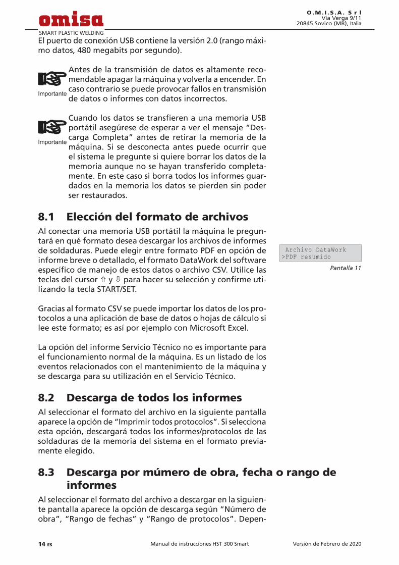
Versión de Febrero de 202014 ES Manual de instrucciones HST 300 Smart
O.M. I . S .A . S r lVia Verga 9/11
20845 Sovico (MB), Italia
El puerto de conexión USB contiene la versión 2.0 (rango máxi-mo datos, 480 megabits por segundo).
Importante
Antes de la transmisión de datos es altamente reco-mendable apagar la máquina y volverla a encender. En caso contrario se puede provocar fallos en transmisión de datos o informes con datos incorrectos.
Importante
CuandolosdatossetransfierenaunamemoriaUSBportátil asegúrese de esperar a ver el mensaje “Des-carga Completa” antes de retirar la memoria de la máquina. Si se desconecta antes puede ocurrir que el sistema le pregunte si quiere borrar los datos de la memoria aunque no se hayan transferido completa-mente. En este caso si borra todos los informes guar-dados en la memoria los datos se pierden sin poder ser restaurados.
8.1 Elección del formato de archivosAl conectar una memoria USB portátil la máquina le pregun-tará en qué formato desea descargar los archivos de informes de soldaduras. Puede elegir entre formato PDF en opción de informe breve o detallado, el formato DataWork del software específicodemanejodeestosdatosoarchivoCSV.Utilicelasteclas del cursor ñ y òparahacersuselecciónyconfirmeuti-lizando la tecla START/SET.
Gracias al formato CSV se puede importar los datos de los pro-tocolos a una aplicación de base de datos o hojas de cálculo si lee este formato; es así por ejemplo con Microsoft Excel.
La opción del informe Servicio Técnico no es importante para el funcionamiento normal de la máquina. Es un listado de los eventos relacionados con el mantenimiento de la máquina y se descarga para su utilización en el Servicio Técnico.
8.2 Descarga de todos los informesAl seleccionar el formato del archivo en la siguiente pantalla aparece la opción de “Imprimir todos protocolos”. Si selecciona esta opción, descargará todos los informes/protocolos de las soldaduras de la memoria del sistema en el formato previa-mente elegido.
8.3 Descarga por múmero de obra, fecha o rango de informes
Al seleccionar el formato del archivo a descargar en la siguien-te pantalla aparece la opción de descarga según “Número de obra”, “Rango de fechas” y “Rango de protocolos”. Depen-
Pantalla 11
Archivo DataWork>PDF resumido
Versión de Febrero de 2020 ES 15Manual de instrucciones HST 300 Smart
O.M. I . S .A . S r lVia Verga 9/1120845 Sovico (MB), Italia
diendo de la selección luego utilice las teclas del cursor ñ y ò para elegir entre los números de obra grabados en el sistema el número de obra deseado de los informes a descargar o puedeutilizarlasteclasconflechaï, ð, ñ, ò para introducir desde que fecha y hasta que fecha o el número del primer y delúltimoprotocoloquedefinenelrangodefechasodein-formesadescargar.AlpresionarlateclaSTART/SETconfirmarálos informes que serán transferidos a la memoria USB portátil.
8.4 Entender el proceso de descarga de los informesLa descarga comienza automáticamente al seleccionar los in-formes deseados. Espere la aparición del mensaje “Descarga finalizada”.
Si ocurre un problema durante el proceso de la transmisión de datos aparece el mensaje “No preparado”. Al solucionar el problema la descarga de datos se reanuda automáticamente.
Info
Sielsistemanotificaunproblemadurantelatrans-misión de datos que no puede ser resuelto durante el proceso aparecerá el mensaje de error “Descarga cancelada”.PulselateclaSTART/SETparaconfirmar.
8.5 Borrado de datos de la memoriaLos datos de los informes almacenados en la memoria de la máquina pueden ser borrados sólo después de su transmisión yaparicióndelmensaje“Descargafinalizada”.Aldesconectarla memoria USB portátil del puerto USB de la máquina aparece el mensaje “Borrar protocolos?”. Si en este momento pulsa la teclaSTART/SETapareceráelmensajedeconfirmación“Bo-rrarprotocolos?Estaseguroborrar?”,paraconfirmarvuelvaa presionar la tecla START/SET. Los datos de la memoria ahora están borrados.
8.6 Dejar grabados los datos en la memoriaAl desconectar la memoria USB portátil del puerto USB de la máquina aparece el mensaje “Borrar protocolos?”. Presione la teclaSTOP/RESETpara seguir teniendo losdatosguarda-dos en la memoria interna de la máquina. Pueden volver a descargarse.
Importante
Acostúmbrese a mantener los datos en la memoria interna según describe el punto 8 del presente ma-nual para mantener la integridad de la información y evitar el borrado no intencionado de los informes de las soldaduras realizadas.
Versión de Febrero de 202016 ES Manual de instrucciones HST 300 Smart
O.M. I . S .A . S r lVia Verga 9/11
20845 Sovico (MB), Italia
9 Información detallada de la máquina
9.1 Características de la máquina en la pantallaLas características técnicas principales de la máquina pueden verse en pantalla presionando la tecla del cursor ð en el paso “Entrar código barras”. Los datos indicados son la versión del software, número de serie de la máquina, la fecha de la si-guiente revisión anual y la cantidad de informes/protocolos de soldadura disponibles para su almacenamiento en la memoria interna.ParasalirdeestapantallapresionelateclaSTOP/RESET.
Si la fecha de la siguiente revisión anual se sobrepasa aparece el mensaje de servicio técnico en la pantalla de la máquina al encenderla,paraconfirmarypasaralsiguientepasopresionela tecla START/SET.
9.2 Medición de resistenciaAl presionar el botón START/SET para iniciar el proceso de soldadura se mide el valor de resistencia del accesorio y se compara con el valor indicado en el código del accesorio. Si la diferencia entre estos dos valores está por debajo de la tolerancia permitida según el código del accesorio se inicia el proceso de soldadura. Si está por encima del nivel de toleran-cia permitido la soldadura está abortada y aparece el mensaje “Error resistencia”. Luego se muestra el nivel de resistencia medido para el accesorio conectado a la máquina.
El motivo de este error puede ser el contacto total no estable-cido con el accesorio o/y terminales de soldadura dañados. En este caso revise los terminales de soldadura y en caso de estar dañados deben ser reemplazados.
9.3 Interruptor de sobrecalentamientoEl proceso de soldadura será abortado en el caso de que el transformador de la máquina alcance la temperatura dema-siado alta. El interruptor del transformador salta y para el proceso de soldadura si la temperatura es demasiado alta y el tiemporestanteparafinalizarelprocesoestáporencimade800 segundos. En la pantalla y en el informe correspondiente aparece el mensaje “Unidad sobrecalentada”.
9.4 Indicación de fallo de alimentación en la última soldadura realizada
El mensaje “Interupción alimentación última soldadura” Indica que la última soldadura realizada fue abortada por un fallo de alimentación. El motivo del fallo puede ser un generador
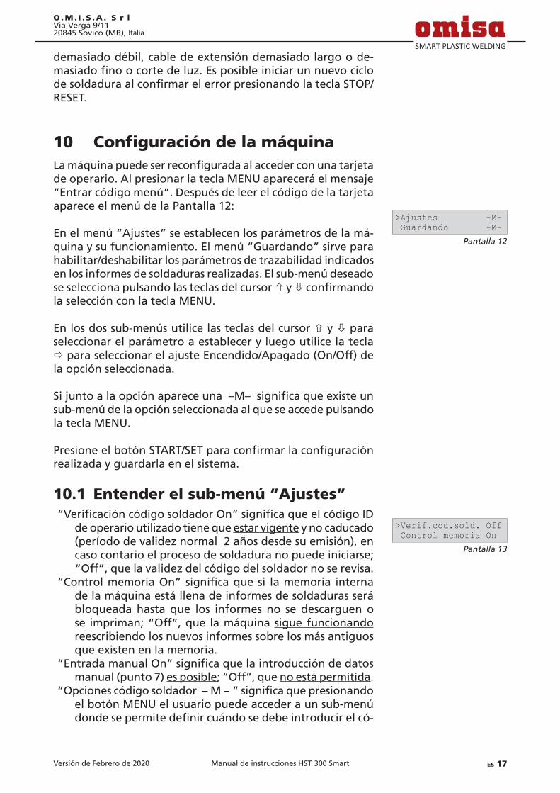
Versión de Febrero de 2020 ES 17Manual de instrucciones HST 300 Smart
O.M. I . S .A . S r lVia Verga 9/1120845 Sovico (MB), Italia
demasiado débil, cable de extensión demasiado largo o de-masiadofinoocortedeluz.EsposibleiniciarunnuevociclodesoldaduraalconfirmarelerrorpresionandolateclaSTOP/RESET.
10 ConfiguracióndelamáquinaLamáquinapuedeserreconfiguradaalaccederconunatarjetade operario. Al presionar la tecla MENU aparecerá el mensaje “Entrar código menú”. Después de leer el código de la tarjeta aparece el menú de la Pantalla 12:
En el menú “Ajustes” se establecen los parámetros de la má-quina y su funcionamiento. El menú “Guardando” sirve para habilitar/deshabilitar los parámetros de trazabilidad indicados en los informes de soldaduras realizadas. El sub-menú deseado se selecciona pulsando las teclas del cursor ñ y òconfirmandola selección con la tecla MENU.
En los dos sub-menús utilice las teclas del cursor ñ y ò para seleccionar el parámetro a establecer y luego utilice la tecla ðparaseleccionarelajusteEncendido/Apagado(On/Off)dela opción seleccionada.
Sijuntoalaopciónapareceuna–M–significaqueexisteunsub-menú de la opción seleccionada al que se accede pulsando la tecla MENU.
PresioneelbotónSTART/SETparaconfirmarlaconfiguraciónrealizada y guardarla en el sistema.
10.1 Entender el sub-menú “Ajustes”“VerificacióncódigosoldadorOn”significaqueelcódigoID
de operario utilizado tiene que estar vigente y no caducado (período de validez normal 2 años desde su emisión), en caso contario el proceso de soldadura no puede iniciarse; “Off”,quelavalidezdelcódigodelsoldadorno se revisa.
“ControlmemoriaOn”significaquesi lamemoria internade la máquina está llena de informes de soldaduras será bloqueada hasta que los informes no se descarguen o se impriman;“Off”,que lamáquinasigue funcionando reescribiendo los nuevos informes sobre los más antiguos que existen en la memoria.
“EntradamanualOn”significaquelaintroduccióndedatosmanual (punto 7) es posible;“Off”,queno está permitida.
“Opcionescódigosoldador–M–”significaquepresionandoel botón MENU el usuario puede acceder a un sub-menú dondesepermitedefinircuándosedebeintroducirelcó-
Pantalla 12
>Ajustes -M- Guardando -M-
Pantalla 13
>Verif.cod.sold. Off Control memoria On
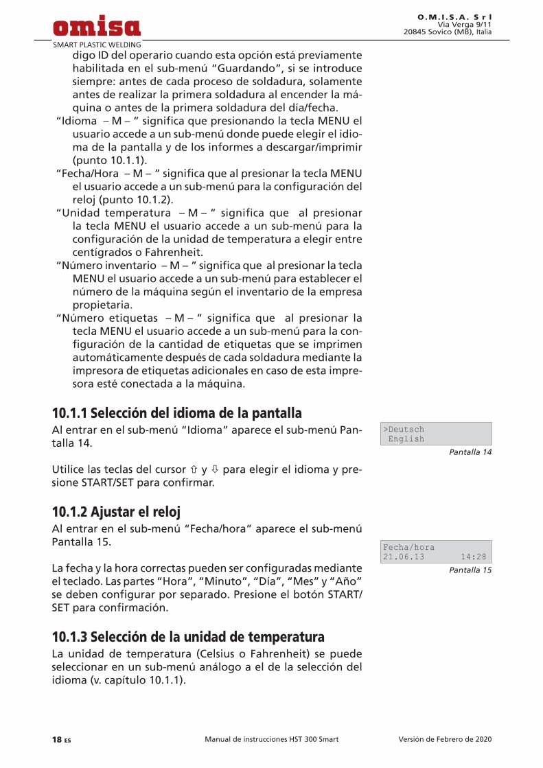
Versión de Febrero de 202018 ES Manual de instrucciones HST 300 Smart
O.M. I . S .A . S r lVia Verga 9/11
20845 Sovico (MB), Italia
digo ID del operario cuando esta opción está previamente habilitada en el sub-menú “Guardando”, si se introduce siempre: antes de cada proceso de soldadura, solamente antes de realizar la primera soldadura al encender la má-quina o antes de la primera soldadura del día/fecha.
“Idioma–M–”significaquepresionandolateclaMENUelusuario accede a un sub-menú donde puede elegir el idio-ma de la pantalla y de los informes a descargar/imprimir (punto 10.1.1).
“Fecha/Hora–M–”significaquealpresionarlateclaMENUelusuarioaccedeaunsub-menúparalaconfiguracióndelreloj (punto 10.1.2).
“Unidad temperatura –M–” significa que al presionarla tecla MENU el usuario accede a un sub-menú para la configuracióndelaunidaddetemperaturaaelegirentrecentígrados o Fahrenheit.
“Númeroinventario–M–”significaquealpresionarlateclaMENU el usuario accede a un sub-menú para establecer el número de la máquina según el inventario de la empresa propietaria.
“Número etiquetas –M–” significa que al presionar latecla MENU el usuario accede a un sub-menú para la con-figuracióndelacantidaddeetiquetasqueseimprimenautomáticamente después de cada soldadura mediante la impresora de etiquetas adicionales en caso de esta impre-sora esté conectada a la máquina.
10.1.1 Selección del idioma de la pantallaAl entrar en el sub-menú “Idioma” aparece el sub-menú Pan-talla 14.
Utilice las teclas del cursor ñ y ò para elegir el idioma y pre-sioneSTART/SETparaconfirmar.
10.1.2 Ajustar el relojAl entrar en el sub-menú “Fecha/hora” aparece el sub-menú Pantalla 15.
Lafechaylahoracorrectaspuedenserconfiguradasmedianteel teclado. Las partes “Hora”, “Minuto”, “Día”, “Mes” y “Año” sedebenconfigurarporseparado.PresioneelbotónSTART/SETparaconfirmación.
10.1.3 Selección de la unidad de temperaturaLa unidad de temperatura (Celsius o Fahrenheit) se puede seleccionar en un sub-menú análogo a el de la selección del idioma (v. capítulo 10.1.1).
Pantalla 14
>Deutsch English
Pantalla 15
Fecha/hora21.06.13 14:28
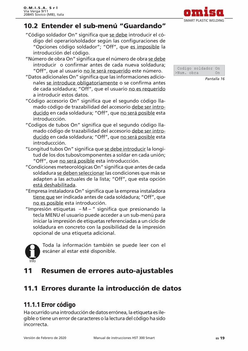
Versión de Febrero de 2020 ES 19Manual de instrucciones HST 300 Smart
O.M. I . S .A . S r lVia Verga 9/1120845 Sovico (MB), Italia
10.2 Entender el sub-menú “Guardando”“CódigosoldadorOn”significaquese debe introducir el có-
digodeloperario/soldadorsegúnlasconfiguracionesde“Opcionescódigosoldador”;“Off”,quees imposible la introducción del código.
“NúmerodeobraOn”significaqueelnúmerodeobrase debe introducir oconfirmarantesdecadanuevasoldadura;“Off”,quealusuariono le será requerido este número.
“DatosadicionalesOn”significaquelasinformacionesadicio-nales se introduce obligatoriamenteoseconfirmaantesdecadasoldadura;“Off”,queelusuariono es requerido a introducir estos datos.
“CódigoaccesorioOn”significaqueelsegundocódigolla-mado código de trazabilidad del accesorio debe ser intro-ducidoencadasoldadura;“Off”,queno será posible esta introduccción.
“CodigosdetubosOn”significaqueelsegundocódigolla-mado código de trazabilidad del accesorio debe ser intro-ducidoencadasoldadura;“Off”,queno será posible esta introduccción.
“LongitudtubosOn”significaquese debe introducir la longi-tud de los dos tubos/componentes a soldar en cada unión; “Off”,queno será posible esta introduccción.
“CondicionesmeteorológicasOn”significaqueantesdecadasoldadura se deben seleccionar las condiciones que más se adaptenalasactualesdelalista;“Off”,queestaopciónestá deshabilitada.
“EmpresainstaladoraOn”significaquelaempresainstaladoratiene queserindicadaantesdecadasoldadura;“Off”,queno es posible esta introducción.
“Impresiónetiquetas –M–” significaquepresionando latecla MENU el usuario puede acceder a un sub-menú para iniciar la impresión de etiquetas referenciadas a un ciclo de soldadura en concreto con la posibilidad de la impresión opcional de una etiqueta adicional.
Info
Toda la información también se puede leer con el escáner al estar esté disponible.
11 Resumen de errores auto-ajustables
11.1 Errores durante la introducción de datos
11.1.1 Error códigoHa ocurrido una introducción de datos errónea, la etiqueta es ile-gible o tiene un error de caracteres o la lectura del código ha sido incorrecta.
Pantalla 16
Codigo soldador On>Num. obra On

Versión de Febrero de 202020 ES Manual de instrucciones HST 300 Smart
O.M. I . S .A . S r lVia Verga 9/11
20845 Sovico (MB), Italia
11.1.2 Sin contactoNo hay un contacto eléctrico correcto entre la máquina y el accesorio (revise los terminales/conectores de soldadura de la máquina) o la resistencia del accesorio es defectuosa.
11.1.3 SubtensiónEl voltaje de entrada es inferior a 175 voltios. Ajuste el voltaje de salida del grupo electrógeno.
11.1.4 SobretensiónEl voltaje de entrada es por encima de 290 voltios. Reduzca el voltaje de salida del grupo electrógeno.
11.1.5 Unidad sobrecalentadaLa temperatura del transformador es demasiado alta. Deje la máquina a enfriarse durante al menos 1 hora.
11.1.6 Error de sistema¡ATENCIÓN!La máquina debe desconectarse tanto de la fuente de ali-mentación como del accesorio inmediatamente. El testado automático de la máquina ha detectado un error del sistema. La máquina no puede seguir funcionando y se debe enviar al servicio técnico autorizado para su revisión y reparación.
11.1.7 Error temperaturaLa temperatura del ambiente exterior está fuera de los límites del correcto funcionamiento de la máquina, es decir por debajo de – 20°C (– 4°F) o por encima de + 60°C (+ 140°F).
11.1.8 Fallo sensor de temperaturaEl sensor de temperatura del ambiente exterior está dañado o defectuoso.
11.1.9 Fallo en relojEl reloj del sistema de la máquina no funciona correctamente o está dañado. Restéelo o envíe la máquina al fabricante/servicio técnico para su ajuste/reparación.
11.1.10 Unidad al SATLa fecha de la revisión anual se ha expirado. El mensaje debe serconfirmadopresionandolateclaSTART/SET.Envíeelequipoal fabricante/Servicio Técnico para su revisión y puesta a punto.
Versión de Febrero de 2020 ES 21Manual de instrucciones HST 300 Smart
O.M. I . S .A . S r lVia Verga 9/1120845 Sovico (MB), Italia
11.1.11 Error de entradaEl código introducido es incorrecto. En caso de introducción de datos manual, no se ha introducido el tiempo de soldadura. Sehaseleccionadounvalorincorrectoenlaconfiguracióndefecha.
11.1.12 Memoria protocolos llenaLa memoria interna está llena de informes/protocolos de sol-dadura. Imprima o descargue los protocolos o deshabilite la opción de control de memoria. Con esta opción deshabilitada el nuevo informe se sobreescribe sobre el informe con el nú-mero más antiguo.
11.1.13 Descarga canceladaDurante la transmisión o impresión de informes ha ocurrido unerrornoidentificado.
11.2 Errores durante el ciclo de soldaduraTodos los errores que ocurren durante el ciclo de soldadura están acompañados de una señal acústica.
11.2.1 SubtensiónEl voltaje de entregada está por debajo de 175 voltios. Si el error persiste durante más de 15 segundos, el proceso de sol-dadura es abortado. Si el voltaje baja a menos de 170 voltios, el proceso de soldadura se aborta inmediatamente.
11.2.2 SobretensiónEl voltaje de entrada está por encima de 290 voltios. Si el error persiste durante más de 15 segundos, el proceso de soldadura es abortado.
11.2.3 Error resistenciaLa resistencia medida del accesorio conectado está fuera de rango de la tolerancia permitida.
11.2.4 Error frecuenciaLa frecuencia del voltaje de entrada está fuera de rango de tolerancia permitida (42 Hz - 69 Hz).
11.2.5 Error tensiónRevise el voltaje y la corriente del grupo electrógeno. El voltaje de salida no corresponde al registrado previamente; la máqui-na se debe enviar al servicio técnico para su revisión/reparación.

Versión de Febrero de 202022 ES Manual de instrucciones HST 300 Smart
O.M. I . S .A . S r lVia Verga 9/11
20845 Sovico (MB), Italia
11.2.6 Corriente bajaEste mensaje de error aparece como consecuencia de un fallo de corriente momentáneo o si la corriente disminuye un 15% por segundo durante 3 segundos.
11.2.7 Corriente altaLa corriente de salida es excesiva; posibles motivos: cortocir-cuito en la espiral calentadora del accesorio o en el cabe de soldadura. Durante la fase de inicio el umbral superior de abor-tarse la soldadura equivale al 1,18 veces del valor al principio, en cualquier otro caso el límite superior depende del valor de carga y se calcula como la corriente del inicio mas un 15%.
11.2.8 Parada de emergenciaEl proceso de soldadura fue interrumpido al presionar la tecla STOP/RESET.
11.2.9 Error bobinaLos valores de la corriente dinámica durante el proceso de soldadura han variado en más de un 15% del valor requerido indicando un cortocircuito en la espiral de calentamiento.
11.2.10 Interrupción alimentación última soldaduraLa última soldadura no se ha completado. La máquina se des-conectó de la fuente de alimentación durante el proceso de soldadura. Para poder seguir utilizando la máquina se debe confirmarelerrorpresionandolateclaSTOP/RESET(punto9.4.).
12 EspecificacionestécnicasRango de funcionamiento accesorios con diá. hasta 160 mmVoltaje nominal 230 VFrecuencia 50 Hz / 60 HzPotencia 1680 VA, 80 % de cicloGrado de protección IP X4Corriente primaria máx. 16 ATemperatura ambiente – 20°C hasta + 60°C (– 4°F hasta + 140°F)Voltaje de salida 8 V - 48 VCorriente máx. de salida 65 AMemoria para informes 500 protocolos de soldaduraPuerto de transmisión de datos USB v 2.0 (480 mbit/s) (ver también las indicaciones de inicio al punto 8)
Tolerancias de medida: Temperatura ± 5 % Voltaje ± 2 % Corriente ± 2 % Resistencia ± 5 %

Versión de Febrero de 2020 ES 23Manual de instrucciones HST 300 Smart
O.M. I . S .A . S r lVia Verga 9/1120845 Sovico (MB), Italia
13 Contacto Servicio Técnico y reparación O.M.I.S.A.Srl Via Verga 9/11 Tel.: +39 039 23 23 028 20845 Sovico (MB), Italia
Web: www.omisa.it Mail: [email protected]
Info
Nosreservamoselderechodemodificacióndeespe-cificacionestécnicasdelproductosinprevioaviso.
14 Accesorios/Recambios del productoConector acodado push-on 4,0 - 4,7 90° 216 - 010 - 440Bolsa conectores 216 - 030 - 310Lápiz óptico 216 - 030 - 270Cable USB 300 - 010 - 167TarjetaIDSoldador/Operario 216-080-031Software DataWork para Windows 216 - 080 - 505Memoria USB tipo “pen” 300 - 010 - 154

DICHIARAZIONE DI CONFORMITÀDeclaración de conformidad
Noi / Nosotros O.M.I.S.A. S r l Via Verga 9/11 I - 20845 Sovico (MB)
dichiariamo sotto la propria responsabilità che il prodottodeclaramos bajo la propia responsabilidad que el producto
HST 300 Smart
Macchina saldatrice per i raccordo di elettrofusione con resistenzaMáquina de soldar para electrofusión con accesorios
alla quale si rifi risce la presente dichiarazione, è conforme alle seguenti norme i documenti di stan-dardizzazioneal cual se refi ere esta declaración es conforme a las siguientes normativas o documentos de nor-malización
Conformità CE / Conformidad CEDir. 2014/30/EU Dir. 2012/19/EUDir. 2014/35/EU Dir. 2011/65/EU
Altre norme / Otras normativasEN 60335-1 EN 61000-3-3:2013EN 60335-2-45 EN 62135-2:2008EN 60529 ISO 12176-2EN 61000-3-2
Nel caso che vengano realizzate modifi cazioni del prodotto senza nostra autorizzazione antecedente scritta o che lo riparino persone non formate e autorizzate da noi, la dichariazone perde ogni validità.En el caso de modifi caciones del producto realizadas sin nuestra previa aprobación y también de re-paros por personas no formadas y autorizadas por nosotros, esta declaración será considerada nulla.
............................................................................CE Marking Date 18.02.2020 Riccardo Cingari Direttore gerente Director gerente
paros por personas no formadas y autorizadas por nosotros, esta declaración será considerada nulla.
............................................................................CE Marking Date 18.02.2020 Riccardo Cingari
Direttore gerente Director gerente
DECLARATION OF CONFORMITYKonformitätserklärung
We / Wir O.M.I.S.A. S r l Via Verga 9/11 I - 20845 Sovico (MB)
declare under our sole responsibility that the producterklären in alleiniger Verantwortung, dass das Produkt
HST 300 Smart
Schweißautomat zur Verarbeitung von Elektroschweiß-FittingsWelding Device for Processing Electrofusion Fittings
to which this declaration relates, are in conformity with the following standards or standardizing doc u mentsauf die sich diese Erklärung bezieht, mit den folgenden Normen oder normativen Dokumenten übereinstimmen
CE Conformity / CE-KonformitätDir. 2014/30/EU Dir. 2012/19/EUDir. 2014/35/EU Dir. 2011/65/EU
Other Standards / Andere NormenEN 60335-1 EN 61000-3-3:2013EN 60335-2-45 EN 62135-2:2008EN 60529 ISO 12176-2EN 61000-3-2
Any and all modifi cations of the device without our prior approval, and any repairs by persons who were not trained and au tho rized by us, shall cause this declaration to become void.Bei einer nicht mit uns abgestimmten Änderung der Maschine oder einer Reparatur von Personen, die nicht von uns im Hause geschult und autorisiert wurden, verliert diese Erklärung ihre Gültigkeit.
............................................................................CE Marking Date 18.02.2020 Riccardo Cingari Managing Director Geschäftsführer
die nicht von uns im Hause geschult und autorisiert wurden, verliert diese Erklärung ihre Gültigkeit.
............................................................................CE Marking Date 18.02.2020 Riccardo Cingari
Managing Director Geschäftsführer