Case Study: Deployment of 300 Smart Motor Control Centers
10
Case Study: Deployment of 300 Smart Motor Control Centers Praveen Subramanian and Scott Manson Schweitzer Engineering Laboratories, Inc. © 2018 IEEE. Personal use of this material is permitted. Permission from IEEE must be obtained for all other uses, in any current or future media, including reprinting/ republishing this material for advertising or promotional purposes, creating new collective works, for resale or redistribution to servers or lists, or reuse of any copyrighted component of this work in other works. This paper was presented at the 65th Annual Petroleum and Chemical Industry Technical Conference, Cincinnati, Ohio, September 24–26, 2018.
-
Upload
khangminh22 -
Category
Documents
-
view
0 -
download
0
Transcript of Case Study: Deployment of 300 Smart Motor Control Centers
Case Study: Deployment of 300 Smart Motor Control Centers
Praveen Subramanian and Scott Manson Schweitzer Engineering Laboratories, Inc.
© 2018 IEEE. Personal use of this material is permitted. Permission from IEEE must be obtained for all other uses, in any current or future media, including reprinting/ republishing this material for advertising or promotional purposes, creating new collective works, for resale or redistribution to servers or lists, or reuse of any copyrighted component of this work in other works.
This paper was presented at the 65th Annual Petroleum and Chemical Industry Technical Conference, Cincinnati, Ohio, September 24–26, 2018.
CASE STUDY: DEPLOYMENT OF 300 SMART MOTOR CONTROL CENTERS Copyright Material IEEE
Praveen Subramanian Member, IEEE Schweitzer Engineering Laboratories, Inc. 420 Exchange, Suite 100 Irvine, CA 92602 USA
Scott Manson Senior Member, IEEE Schweitzer Engineering Laboratories, Inc. 2350 NE Hopkins Court Pullman, WA 99163 USA
Abstract—This paper describes the design of, and the lessons learned from, a deployment of 300 smart motor control centers for a large oil and gas project in Eurasia. The same smart electronics were deployed in motor control centers manufactured by three different suppliers. The standardization of communication, power system protection, and automation designs across the entire project reduced the need for spare parts, provided consistency across all locations, integrated condition monitoring equipment, and provided interfaces to process control systems. Arc-flash and conventional protection schemes were provided. Manufacturing, testing, and design methods are shared in this paper.
Index Terms—Motor control center, arc flash, protection, condition monitoring.
I. INTRODUCTION
This paper describes a centralized smart motor control system (CSMCS) design that uses low-voltage motor protective relays (LVMPRs) instead of programmable logic controllers (PLCs). Previous smart motor control center (MCC) designs used simple motor overload devices in the MCC drawer (also known as a bucket) and digital communications to PLCs.
Distributed protective relays offer greater safety, reliability, functionality, programmability, flexibility, and cybersecurity than PLCs in a lower cost solution with a smaller form factor. The relay-centric MCC design also allows the integration of arc-flash mitigation technologies, current transformers (CTs), and condition monitoring systems such as joint thermal monitoring and partial discharge systems. The CSMCS ensures that start and stop control commands from the process control system (PCS) interfaces reach the wired motor contactors in less than 150 milliseconds.
This paper describes the deployment of 300 smart MCCs for a large oil and gas project in Eurasia. The paper starts with a synopsis of the challenges posed by this project, followed by a review of the communications architecture of the system. Various key technologies—such as arc-flash mitigation, time synchronization, protection coordination, automation and human-machine interface (HMI) systems, process control interfaces, and condition monitoring systems—are explained. The paper concludes with key takeaways from the design, procurement, and testing of this system.
II. PROBLEM STATEMENT
The primary goal for this project is to ensure minimal site commissioning. This is critical because the project is in a remote location, has limited skilled labor, and has aggressive timelines for installation. This is being accomplished by delivering fully tested systems, minimizing complexity, and using electronic devices with an excess of 300 years mean time between failures. Quality is especially important because a defect could propagate across the system’s 5,000 low-voltage protective relays and 300 MCCs.
Another challenge for this project was to supply consistent equipment, settings, and designs to three different MCC manufacturers in Europe. These MCC manufacturers installed standardized low-voltage relays into their MCCs. A set of standardized schematics and relays for each MCC drawer application was created and supplied to each manufacturer to implement a consistent control and wiring approach.
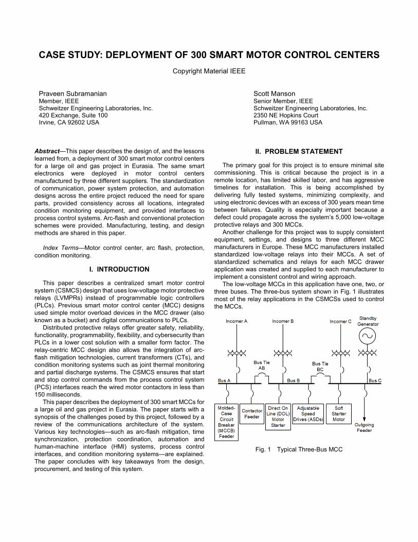
The low-voltage MCCs in this application have one, two, or three buses. The three-bus system shown in Fig. 1 illustrates most of the relay applications in the CSMCSs used to control the MCCs.
Fig. 1 Typical Three-Bus MCC
III. COMMUNICATIONS ARCHITECTURE
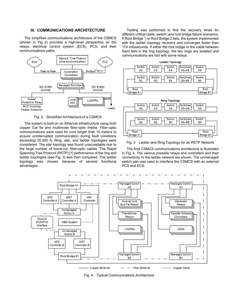
The simplified communications architecture of the CSMCS (shown in Fig. 2) provides a high-level perspective on the relays, electrical control system (ECS), PCS, and their communications paths.
Fig. 2 Simplified Architecture of a CSMCS
The system is built on an Ethernet infrastructure using both copper Cat 5e and multimode fiber-optic media. Fiber-optic communications were used for runs longer than 10 meters to ensure uninterrupted communication during fault conditions exceeding 20,000 A. Ring, star, and ladder topologies were considered. The star topology was found unacceptable due to the large number of home-run fiber-optic cables. The Rapid Spanning Tree Protocol (RSTP) [1] performance of the ring and ladder topologies (see Fig. 3) was then compared. The ladder topology was chosen because of several functional advantages.
Testing was performed to find the recovery times for different critical cable, switch, and root bridge failure scenarios. If Root Bridge 1 or Root Bridge 2 fails, the system implemented with the ladder topology recovers and converges faster than 174 milliseconds. If either the root bridge or the cable between them fails in the ring topology, the two rings are isolated and communications are lost with some relays.
Fig. 3 Ladder and Ring Topology for an RSTP Network
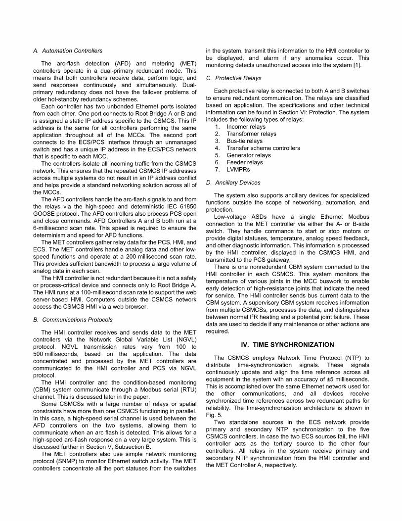
The final CSMCS communications architecture is illustrated in Fig. 4. The various possible relays and controllers and their connectivity to the ladder network are shown. The unmanaged switch pair was used to interface the CSMCS with an external PCS and ECS.
Fig. 4 Typical Communications Architecture
A. Automation Controllers
The arc-flash detection (AFD) and metering (MET) controllers operate in a dual-primary redundant mode. This means that both controllers receive data, perform logic, and send responses continuously and simultaneously. Dual-primary redundancy does not have the failover problems of older hot-standby redundancy schemes.
Each controller has two unbonded Ethernet ports isolated from each other. One port connects to Root Bridge A or B and is assigned a static IP address specific to the CSMCS. This IP address is the same for all controllers performing the same application throughout all of the MCCs. The second port connects to the ECS/PCS interface through an unmanaged switch and has a unique IP address in the ECS/PCS network that is specific to each MCC.
The controllers isolate all incoming traffic from the CSMCS network. This ensures that the repeated CSMCS IP addresses across multiple systems do not result in an IP address conflict and helps provide a standard networking solution across all of the MCCs.
The AFD controllers handle the arc-flash signals to and from the relays via the high-speed and deterministic IEC 61850 GOOSE protocol. The AFD controllers also process PCS open and close commands. AFD Controllers A and B both run at a 6-millisecond scan rate. This speed is required to ensure the determinism and speed for AFD functions.
The MET controllers gather relay data for the PCS, HMI, and ECS. The MET controllers handle analog data and other low-speed functions and operate at a 200-millisecond scan rate. This provides sufficient bandwidth to process a large volume of analog data in each scan.
The HMI controller is not redundant because it is not a safety or process-critical device and connects only to Root Bridge A. The HMI runs at a 100-millisecond scan rate to support the web server-based HMI. Computers outside the CSMCS network access the CSMCS HMI via a web browser.
B. Communications Protocols
The HMI controller receives and sends data to the MET controllers via the Network Global Variable List (NGVL) protocol. NGVL transmission rates vary from 100 to 500 milliseconds, based on the application. The data concentrated and processed by the MET controllers are communicated to the HMI controller and PCS via NGVL protocol.
The HMI controller and the condition-based monitoring (CBM) system communicate through a Modbus serial (RTU) channel. This is discussed later in the paper.
Some CSMCSs with a large number of relays or spatial constraints have more than one CSMCS functioning in parallel. In this case, a high-speed serial channel is used between the AFD controllers on the two systems, allowing them to communicate when an arc flash is detected. This allows for a high-speed arc-flash response on a very large system. This is discussed further in Section V, Subsection B.
The MET controllers also use simple network monitoring protocol (SNMP) to monitor Ethernet switch activity. The MET controllers concentrate all the port statuses from the switches
in the system, transmit this information to the HMI controller to be displayed, and alarm if any anomalies occur. This monitoring detects unauthorized access into the system [1].
C. Protective Relays
Each protective relay is connected to both A and B switches to ensure redundant communication. The relays are classified based on application. The specifications and other technical information can be found in Section VI: Protection. The system includes the following types of relays:
1. Incomer relays 2. Transformer relays 3. Bus-tie relays 4. Transfer scheme controllers 5. Generator relays 6. Feeder relays 7. LVMPRs
D. Ancillary Devices
The system also supports ancillary devices for specialized functions outside the scope of networking, automation, and protection.
Low-voltage ASDs have a single Ethernet Modbus connection to the MET controller via either the A- or B-side switch. They handle commands to start or stop motors or provide digital statuses, temperature, analog speed feedback, and other diagnostic information. This information is processed by the HMI controller, displayed in the CSMCS HMI, and transmitted to the PCS gateway.
There is one nonredundant CBM system connected to the HMI controller in each CSMCS. This system monitors the temperature of various joints in the MCC buswork to enable early detection of high-resistance joints that indicate the need for service. The HMI controller sends bus current data to the CBM system. A supervisory CBM system receives information from multiple CSMCSs, processes the data, and distinguishes between normal I2R heating and a potential joint failure. These data are used to decide if any maintenance or other actions are required.
IV. TIME SYNCHRONIZATION
The CSMCS employs Network Time Protocol (NTP) to distribute time-synchronization signals. These signals continuously update and align the time reference across all equipment in the system with an accuracy of ±5 milliseconds. This is accomplished over the same Ethernet network used for the other communications, and all devices receive synchronized time references across two redundant paths for reliability. The time-synchronization architecture is shown in Fig. 5.
Two standalone sources in the ECS network provide primary and secondary NTP synchronization to the five CSMCS controllers. In case the two ECS sources fail, the HMI controller acts as the tertiary source to the other four controllers. All relays in the system receive primary and secondary NTP synchronization from the HMI controller and the MET Controller A, respectively.
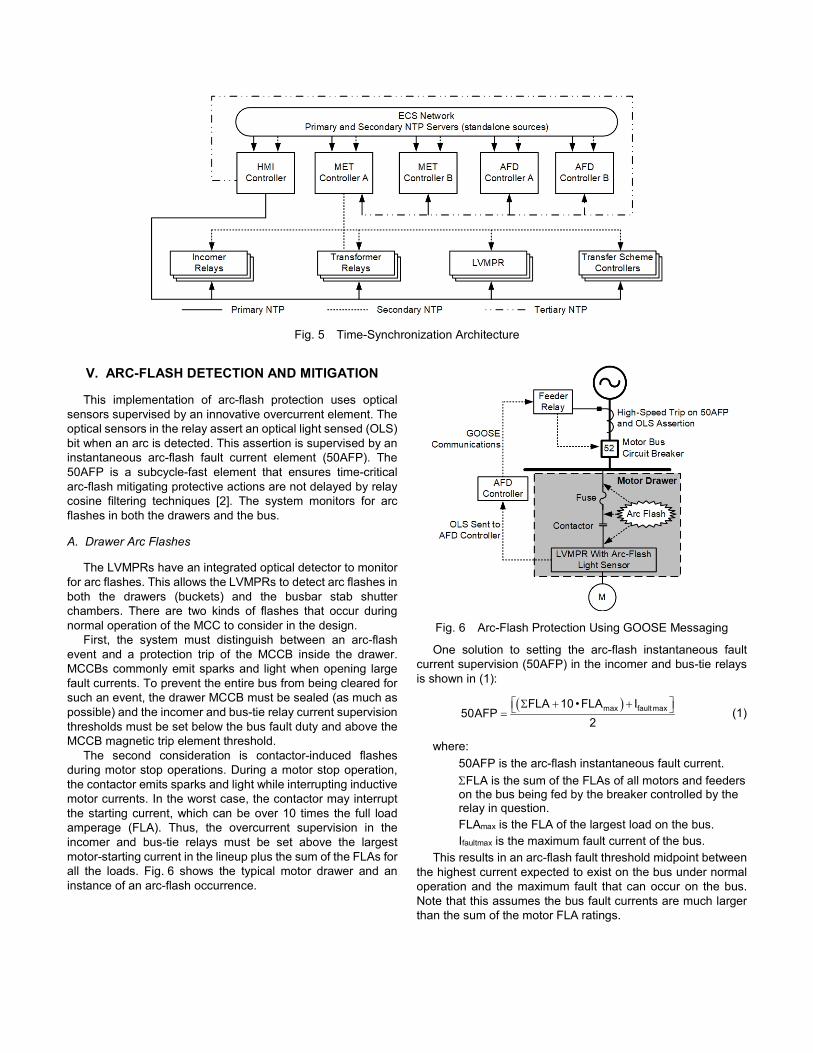
Fig. 5 Time-Synchronization Architecture
V. ARC-FLASH DETECTION AND MITIGATION
This implementation of arc-flash protection uses optical sensors supervised by an innovative overcurrent element. The optical sensors in the relay assert an optical light sensed (OLS) bit when an arc is detected. This assertion is supervised by an instantaneous arc-flash fault current element (50AFP). The 50AFP is a subcycle-fast element that ensures time-critical arc-flash mitigating protective actions are not delayed by relay cosine filtering techniques [2]. The system monitors for arc flashes in both the drawers and the bus.
A. Drawer Arc Flashes
The LVMPRs have an integrated optical detector to monitor for arc flashes. This allows the LVMPRs to detect arc flashes in both the drawers (buckets) and the busbar stab shutter chambers. There are two kinds of flashes that occur during normal operation of the MCC to consider in the design.
First, the system must distinguish between an arc-flash event and a protection trip of the MCCB inside the drawer. MCCBs commonly emit sparks and light when opening large fault currents. To prevent the entire bus from being cleared for such an event, the drawer MCCB must be sealed (as much as possible) and the incomer and bus-tie relay current supervision thresholds must be set below the bus fault duty and above the MCCB magnetic trip element threshold.
The second consideration is contactor-induced flashes during motor stop operations. During a motor stop operation, the contactor emits sparks and light while interrupting inductive motor currents. In the worst case, the contactor may interrupt the starting current, which can be over 10 times the full load amperage (FLA). Thus, the overcurrent supervision in the incomer and bus-tie relays must be set above the largest motor-starting current in the lineup plus the sum of the FLAs for all the loads. Fig. 6 shows the typical motor drawer and an instance of an arc-flash occurrence.
Fig. 6 Arc-Flash Protection Using GOOSE Messaging
One solution to setting the arc-flash instantaneous fault current supervision (50AFP) in the incomer and bus-tie relays is shown in (1):
( )max faultmaxFLA 10 •FLA I
50AFP2
Σ + + = (1)
where: 50AFP is the arc-flash instantaneous fault current. ΣFLA is the sum of the FLAs of all motors and feeders on the bus being fed by the breaker controlled by the relay in question. FLAmax is the FLA of the largest load on the bus. Ifaultmax is the maximum fault current of the bus.
This results in an arc-flash fault threshold midpoint between the highest current expected to exist on the bus under normal operation and the maximum fault that can occur on the bus. Note that this assumes the bus fault currents are much larger than the sum of the motor FLA ratings.
B. Bus Arc Flashes
Incomer, generator, and bus-tie circuit breakers are opened by relays during an arc-flash event. All bus arc flashes are monitored by loop fibers that pass around the MCC buswork. Protective relays placed at each incomer, generator, and bus tie support four fiber loops each. Flash sensors in the incomer, generator, and bus-tie relays are supervised by the 50AFP element described previously.
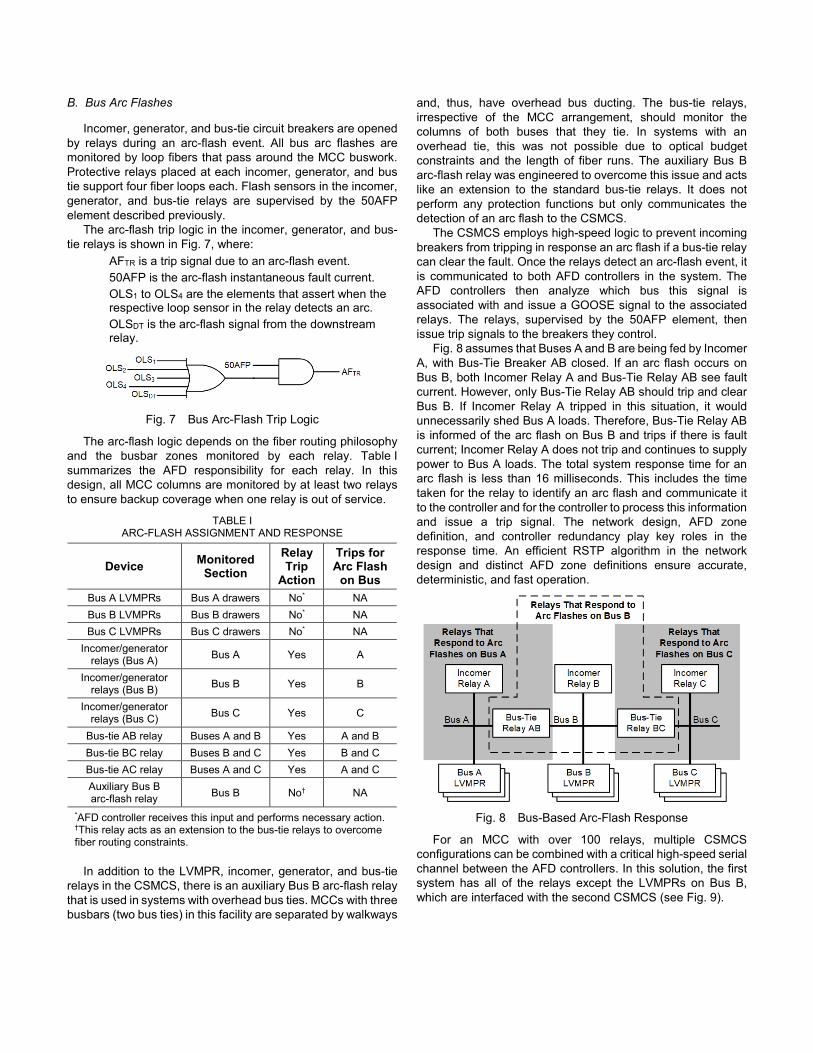
The arc-flash trip logic in the incomer, generator, and bus-tie relays is shown in Fig. 7, where:
AFTR is a trip signal due to an arc-flash event. 50AFP is the arc-flash instantaneous fault current. OLS1 to OLS4 are the elements that assert when the respective loop sensor in the relay detects an arc. OLSDT is the arc-flash signal from the downstream relay.
Fig. 7 Bus Arc-Flash Trip Logic
The arc-flash logic depends on the fiber routing philosophy and the busbar zones monitored by each relay. Table I summarizes the AFD responsibility for each relay. In this design, all MCC columns are monitored by at least two relays to ensure backup coverage when one relay is out of service.
TABLE I ARC-FLASH ASSIGNMENT AND RESPONSE
Device Monitored Section
Relay Trip
Action
Trips for Arc Flash
on Bus Bus A LVMPRs Bus A drawers No* NA Bus B LVMPRs Bus B drawers No* NA Bus C LVMPRs Bus C drawers No* NA
Incomer/generator relays (Bus A) Bus A Yes A
Incomer/generator relays (Bus B) Bus B Yes B
Incomer/generator relays (Bus C) Bus C Yes C
Bus-tie AB relay Buses A and B Yes A and B Bus-tie BC relay Buses B and C Yes B and C Bus-tie AC relay Buses A and C Yes A and C Auxiliary Bus B arc-flash relay Bus B No† NA
*AFD controller receives this input and performs necessary action. †This relay acts as an extension to the bus-tie relays to overcome fiber routing constraints.
In addition to the LVMPR, incomer, generator, and bus-tie relays in the CSMCS, there is an auxiliary Bus B arc-flash relay that is used in systems with overhead bus ties. MCCs with three busbars (two bus ties) in this facility are separated by walkways
and, thus, have overhead bus ducting. The bus-tie relays, irrespective of the MCC arrangement, should monitor the columns of both buses that they tie. In systems with an overhead tie, this was not possible due to optical budget constraints and the length of fiber runs. The auxiliary Bus B arc-flash relay was engineered to overcome this issue and acts like an extension to the standard bus-tie relays. It does not perform any protection functions but only communicates the detection of an arc flash to the CSMCS.
The CSMCS employs high-speed logic to prevent incoming breakers from tripping in response an arc flash if a bus-tie relay can clear the fault. Once the relays detect an arc-flash event, it is communicated to both AFD controllers in the system. The AFD controllers then analyze which bus this signal is associated with and issue a GOOSE signal to the associated relays. The relays, supervised by the 50AFP element, then issue trip signals to the breakers they control.
Fig. 8 assumes that Buses A and B are being fed by Incomer A, with Bus-Tie Breaker AB closed. If an arc flash occurs on Bus B, both Incomer Relay A and Bus-Tie Relay AB see fault current. However, only Bus-Tie Relay AB should trip and clear Bus B. If Incomer Relay A tripped in this situation, it would unnecessarily shed Bus A loads. Therefore, Bus-Tie Relay AB is informed of the arc flash on Bus B and trips if there is fault current; Incomer Relay A does not trip and continues to supply power to Bus A loads. The total system response time for an arc flash is less than 16 milliseconds. This includes the time taken for the relay to identify an arc flash and communicate it to the controller and for the controller to process this information and issue a trip signal. The network design, AFD zone definition, and controller redundancy play key roles in the response time. An efficient RSTP algorithm in the network design and distinct AFD zone definitions ensure accurate, deterministic, and fast operation.
Fig. 8 Bus-Based Arc-Flash Response
For an MCC with over 100 relays, multiple CSMCS configurations can be combined with a critical high-speed serial channel between the AFD controllers. In this solution, the first system has all of the relays except the LVMPRs on Bus B, which are interfaced with the second CSMCS (see Fig. 9).
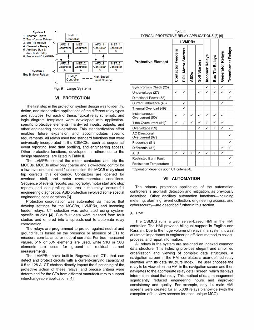
Fig. 9 Large Systems
VI. PROTECTION
The first step in the protection system design was to identify, define, and standardize applications of the different relay types and subtypes. For each of these, typical relay schematic and logic diagram templates were developed with application-specific protective elements, hardwired inputs, outputs, and other engineering considerations. This standardization effort enables future expansion and accommodates specific requirements. All relays used had standard functions that were universally incorporated in the CSMCSs, such as sequential event reporting, load data profiling, and engineering access. Other protective functions, developed in adherence to the design standards, are listed in Table II.
The LVMPRs control the motor contactors and trip the MCCBs. MCCBs allow only coarse and slow-acting control for a low-level or unbalanced fault condition; the MCCB relay shunt trip corrects this deficiency. Contactors are opened for overload, stall, and motor overtemperature conditions. Sequence of events reports, oscillography, motor start and stop reports, and load profiling features in the relays ensure full engineering diagnostics. ASD protection involved some special engineering considerations [3].
Protection coordination was automated via macros that develop settings for the MCCBs, LVMPRs, and incoming feeder relays. CT selection was automated using system-specific studies [4]. Bus fault data were gleaned from fault studies and entered into a spreadsheet to automate relay coordination.
The relays are programmed to protect against neutral and ground faults based on the presence or absence of CTs to measure core-balance or neutral currents. For true measured values, 51N or 50N elements are used, while 51G or 50G elements are used for ground or residual current measurements.
The LVMPRs have built-in Rogowski-coil CTs that can detect and protect circuits with a current-carrying capacity of 0.5 to 128 A. CT choices directly impact the functioning of the protective action of these relays, and precise criteria were determined for the CTs from different manufacturers to support interchangeable applications [4].
TABLE II TYPICAL PROTECTIVE RELAY APPLICATIONS [5] [6]
Protective Element
LVMPRs
Inco
mer
Rel
ays
Bus
-Tie
Rel
ays
Gen
erat
or R
elay
s
Tran
sfor
mer
Rel
ays
Con
tact
or F
eede
rs
DO
L M
otor
Sta
rter
s
ASD
s
Soft
Star
ters
Synchronism Check (25) Undervoltage (27)
Directional Power (32) Current Imbalance (46) Thermal Overload (49)* Instantaneous Overcurrent (50)*
Time Overcurrent (51)*
Overvoltage (59)
AC Directional Overcurrent (67)
Frequency (81)
Differential (87) AFD
Restricted Earth Fault Resistance Temperature
*Operation depends upon CT criteria [4].
VII. AUTOMATION
The primary protection application of the automation controllers is arc-flash detection and mitigation, as previously described. Other ancillary automation functions—including metering, alarming, event collection, engineering access, and cybersecurity—are described further in this section.
A. HMI
The CSMCS runs a web server-based HMI in the HMI controller. The HMI provides bilingual support in English and Russian. Due to the huge volume of relays in a system, it was of utmost importance to engineer an efficient method to collect, process, and report information.
All relays in the system are assigned an indexed common data structure. This indexing provides elegant and simplified organization and viewing of complex data structures. A navigation screen in the HMI correlates a user-defined relay identifier with its data structure index. The user chooses the relay to be viewed on the HMI in the navigation screen and then navigates to the appropriate relay detail screen, which displays information about that relay. This method of data management significantly reduced engineering hours and improved consistency and quality. For example, only 14 main HMI screens were created for all 5,000 relays plant-wide (with the exception of bus view screens for each unique MCC).
B. Data and Alarm Reporting
Smart metering, data reporting, and alarming techniques are implemented in this solution. The CSMCS HMI consolidates and displays all the alarms. A smaller set of summary alarms are shared with the ECS and PCS to simplify alarming. ECS alarming focuses on the electrical infrastructure, while the PCS alarming focuses on process-related equipment. For example, information about all LVMPRs and ASDs is communicated to the PCS, while information from incomer, bus-tie, and generator relays is communicated to the ECS. All communications are monitored by active watchdogs and counters rather than the contemporary “offline” bit. This ensures a high-integrity health evaluation of communication links.
C. Sequential Event Records
Time-stamped binary sequential event records (SERs) are recorded in the relays and archived for long-term storage. SERs capture information about critical electrical system state changes. SERs are saved in a central repository for ease of access, viewing, and analysis.
Time-stamped oscillographic event records (ERs) are also recorded in the relays and archived for long-term storage. ERs include analog signals such as current, voltage, and binary state information. They are used to correlate events with the larger electrical system. Only ERs from the incomer, bus-tie, and generator relays and the transfer scheme controllers are archived. The LVMPRs also capture ERs and can be accessed through a remote connection from the ECS network or directly through the local CSMCS network.
D. Engineering Access
The HMI controller has access point routers configured to establish a transparent connection from the ECS to the relays in the CSMCS. This mode of engineering access allows updates, backup, and other maintenance to be performed remotely and securely. ERs and SERs for the LVMPRs can be accessed in this manner.
VIII. PROCESS CONTROL INTERFACE
The PCS communicates via a single Modbus/TCP communications link to each MCC. The status of an entire MCC can be polled with a single Modbus read command, and the controls for all drawers are accomplished with a single Modbus write command. This consolidation of all status, metering, and controls information at a single Modbus map was accomplished by the protocol gateways in the PCS network shown in Fig. 2. Once control messages reach the gateways, the LVMPR receives them within 100 milliseconds, ensuring fast control of contactors, ASDs, and soft starters.
IX. PROCUREMENT, DEVELOPMENT, AND DEPLOYMENT
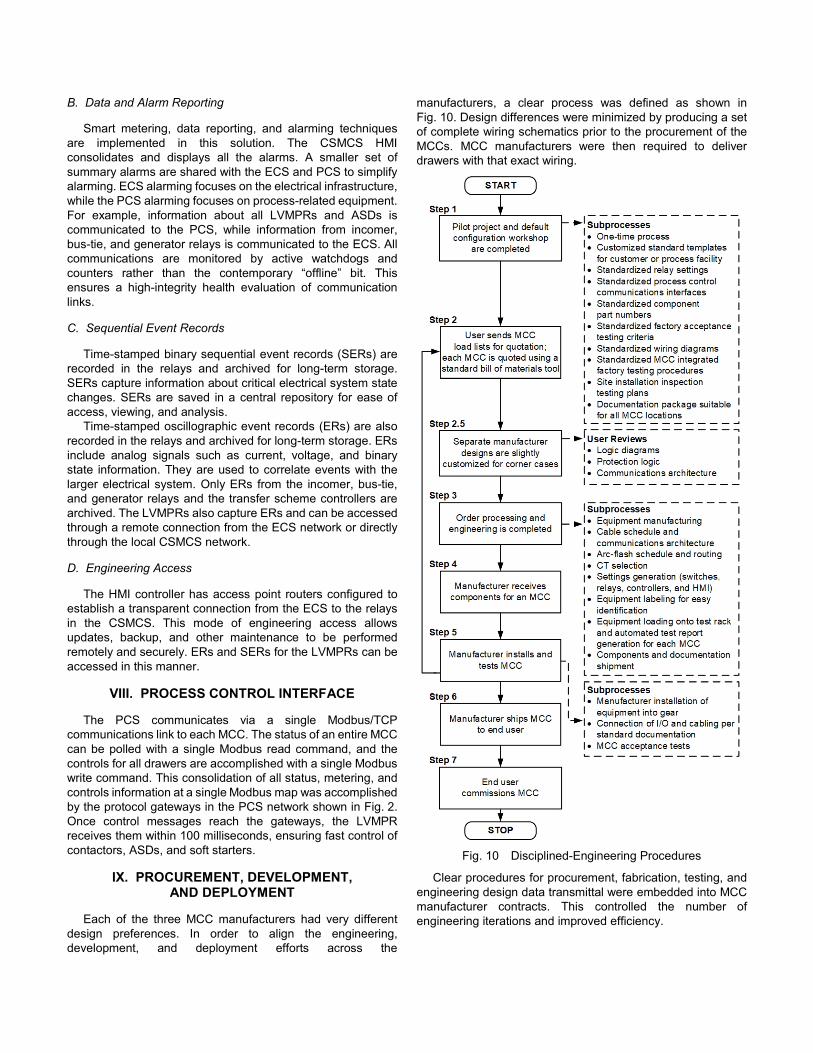
Each of the three MCC manufacturers had very different design preferences. In order to align the engineering, development, and deployment efforts across the
manufacturers, a clear process was defined as shown in Fig. 10. Design differences were minimized by producing a set of complete wiring schematics prior to the procurement of the MCCs. MCC manufacturers were then required to deliver drawers with that exact wiring.
Fig. 10 Disciplined-Engineering Procedures
Clear procedures for procurement, fabrication, testing, and engineering design data transmittal were embedded into MCC manufacturer contracts. This controlled the number of engineering iterations and improved efficiency.
Ensuring consistency ensured quality. Wiring and logic diagrams were standardized for each type of drawer (motor starter, feeder, ASD, soft starter, and so on). The firmware of all electronics was standardized to guarantee absolute consistency across all facilities. Consistent designs were challenging because the same smart electronics were deployed in MCCs manufactured by three different suppliers.
Automated settings creation tools led to a significant reduction in delivery lead times and ensured that the system was fully functioning as delivered. The entry point for these tools was a system definition spreadsheet. This one spreadsheet contained all the information required to define the settings, protection, automation, and communications of an entire MCC. Based on simplified data (FLA, motor type, drawer type, MCCB size, etc.), the automated tool selected CT sizes and created relay settings, communications mapping, HMI settings, controller settings, and so on. By using a single point of data entry, all the automation, protection, control, security, and network engineering processes were streamlined.
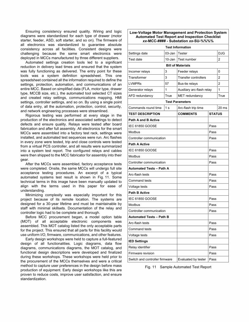
Rigorous testing was performed at every stage in the production of the electronics and associated settings to detect defects and ensure quality. Relays were tested after board fabrication and after full assembly. All electronics for the smart MCCs were assembled into a factory test rack, settings were installed, and automated test sequences were run. Arc flashes in every zone were tested, trip and close controls were tested from a virtual PCS controller, and all results were summarized into a system test report. The configured relays and cables were then shipped to the MCC fabricator for assembly into their gear.
After the MCCs were assembled, factory acceptance tests were completed. Onsite, the same MCCs will undergo full site acceptance testing procedures. An excerpt of a typical automated systems test result is shown in Fig. 11. Some technical terms in this image have been manually updated to align with the terms used in this paper for ease of understanding.
Minimizing complexity was especially important for this project because of its remote location. The systems are designed for a 30-year lifetime and must be maintainable by staff with minimal skillsets. Documentation of the relay and controller logic had to be complete and thorough.
Before MCC procurement began, a model option table (MOT) of all acceptable electronic components was assembled. This MOT catalog listed the only acceptable parts for the project. This ensured that all parts for this facility would use uniform I/O, firmware, communications, and other features.
Early design workshops were held to capture a full-featured design of all functionalities. Logic diagrams, data flow diagrams, communications diagrams, the MOT catalog, and functional design descriptions were developed and finalized during these workshops. These workshops were held prior to the procurement of the MCCs themselves and were a critical method to capture user preferences in the design before mass production of equipment. Early design workshops like this are proven to reduce costs, improve user satisfaction, and ensure standardization.
Low-Voltage Motor Management and Protection System Automated Test Report and Inspection Checklist
xx-MCC-#### - Substation xx-SU-%%%% Test Information
Settings date 03-Jan Tester DJG
Test date 10-Jan Test number 2
Bill of Materials
Incomer relays 3 Feeder relays 0
Transformer 3 Transfer controllers 2
LVMPRs 57 Bus-tie relays 2
Generator relays 1 Auxiliary arc-flash relay 1
AFD redundancy True MET redundancy True
Test Parameters
Commands round time 1 s Arc-flash trip time 20 ms
TEST DESCRIPTION COMMENTS STATUS
Path A and B Active
IEC 61850 GOOSE Pass
Modbus Pass
Controller communication Pass
Path A Active
IEC 61850 GOOSE Pass
Modbus Pass
Controller communication Pass
Automated Tests – Path A
Arc-flash tests Pass
Command tests Pass
Voltage tests Pass
Path B Active
IEC 61850 GOOSE Pass
Modbus Pass
Controller communication Pass
Automated Tests – Path B
Arc-flash tests Pass
Command tests Pass
Voltage tests Pass
IED Settings
Relay identifier Pass
Firmware revision Pass
Switch and controller firmware Evaluated by tester Pass
Fig. 11 Sample Automated Test Report
X. CONCLUSIONS
Integrating distributed protective relays into low-voltage MCC drawers at this facility provided substantial improvements including:
1. Arc flashes detected and trip signals issued within 1 cycle.
2. Enhanced cybersecurity and network visibility. 3. Standardized system factory testing reports. 4. A consistent look and feel for operators, even across
MCCs from different manufacturers. 5. One smart relay model for all types of drawers. 6. Elimination of costly PLCs and associated cabinets and
wiring. 7. Improved root-cause analysis with advanced relay
features. 8. A single communications channel for PCS control of all
motor loads.
XI. REFERENCES
[1] S. Manson and D. Anderson, “Practical Cybersecurity for Protection and Control System Communications Networks,” proceedings of the 64th Annual Petroleum and Chemical Industry Technical Conference, Calgary, Canada, September 2017.
[2] G. Rocha, E. Zanirato, F. Ayello, and R. Taninaga, “Arc-Flash Protection for Low- and Medium-Voltage Panels,” proceedings of the 58th Annual Petroleum and Chemical Industry Technical Conference, Toronto, ON, September 2011.
[3] A. D’Aversa, B. Hughes, and S. Patel, “Challenges and Solutions of Protecting Variable Speed Drive Motors,” proceedings of the 66th Annual Conference for Protective Relay Engineers, College Station, TX, April 2013.
[4] S. Manson and A. Upreti, “Current Transformer Selection Techniques for Low-Voltage Motor Control Centers,” proceedings of the 63rd Annual Petroleum and Chemical Industry Technical Conference, Philadelphia, PA, September 2016.
[5] S. Manson, B. Hughes, R. D. Kirby, and H. L. Floyd, “Best Practices for Motor Control Center Protection and Control,” proceedings of the 60th Annual Petroleum and Chemical Industry Technical Conference, Chicago, IL, September 2013.
[6] J. L. Blackburn, Protective Relaying: Principles and Applications, Marcel Dekker Inc., New York, NY, 1987.
XII. VITAE
Praveen Subramanian received his M.S.E.E. in electrical engineering from Arizona State University in 2012 and his B.E. in electrical and electronics engineering from Anna University in Chennai, India, in 2009. He joined Schweitzer Engineering Laboratories, Inc. in 2012 as an automation engineer. Praveen has since been involved with power management, substation automation, integration, control, and monitoring systems for electric utilities, water districts, and oil fields. He is a registered professional engineer in California. He can be contacted at [email protected].
Scott Manson received his M.S.E.E. in electrical engineering from the University of Wisconsin–Madison and his B.S.E.E. in electrical engineering from Washington State University. Scott is currently the Engineering Services Technology Director at Schweitzer Engineering Laboratories, Inc. In this role, he provides consulting services on control and protection systems worldwide. He has significant experience in power system protection, real-time modeling, power management and microgrid control systems, remedial action schemes, turbine control, multi-axis motion control, web line control, robotic assembly, and precision machine tools. Scott is a registered professional engineer in Washington, Alaska, North Dakota, Idaho, and Louisiana. He can be contacted at [email protected].
Previously presented at the 65th Annual Petroleum and Chemical Industry Technical Conference, Cincinnati, Ohio, September 2018.
© 2018 IEEE – All rights reserved. 20180419 • TP6855