SPLL design to flux oriented of a VSC interface for wind power applications
21
1 November, 2005 IECON 2005 SPLL Design to flux oriented of a VSC interface for Wind Power Applications Department of Electronics. Alcalá University. 28871 Alcalá de Henares, Madrid, Spain [email protected] Emilio J. Bueno, Francisco J. Rodríguez, Felipe Espinosa, Santiago Cobreces
Transcript of SPLL design to flux oriented of a VSC interface for wind power applications

1November, 2005 IECON 2005
SPLL Design to flux oriented of a VSC interface for Wind Power Applications
Department of Electronics. Alcalá University.28871 Alcalá de Henares, Madrid, Spain
Emilio J. Bueno, Francisco J. Rodríguez, Felipe Espinosa, Santiago Cobreces

2November, 2005 IECON 2005
ContentsContents
1. Introduction.
2. SPLL structure.
3. Tuning of SPLL constants.
4. Simulation results.
5. Practical results.
6. Summary and Conclusions.

3November, 2005 IECON 2005
Introduction (1/2)Introduction (1/2)
Accurate phase information of the grid voltage is crucial for most of modern power electronic systems such as VSC connected to the grid.
uDC
ua(t) ea(t)
eb(t)
ec(t)
pulses
)(* kudqr )(kidq
r
( ) ( )kek dqr,θ
)(kid∗
CDC
)(kuDC)(kuDC
∗ )(kiq∗
uc(t)
L1
ub(t) L1
uDC meas.
PWM generator
Current control
Current meas. Grid voltage
meas. ADC & SPLL
L1
DC control
1DCi2DCi
)(_ ti abcg
r
)(_ te abcgr
( )kigr
αβ→abc
PLL
ADC
( )ti abcg _r
( )kiαβr
dq→αβ
( )kegr
ADC
( )te abcg _r
αβ→abc
( )keαβr
dq→αβ( )kθ
( )kidqr
αβ→dq
23 1
STωabc→αβ
PWM
( )kedqr ( )kθ ( )1+∗ kur
( )1+∗ kuαβr
( )1+∗ kuabcr
to IGBT’s
Current vectorial controller
ADC
( )tuDC
++
( )kidq∗v
( )kuDC
SPLL
Objective: Exact synchronization of the VSC current control with the phase of the positive sequence of the fundamental harmonic of the grid voltage.

4November, 2005 IECON 2005
Introduction (2/2)Introduction (2/2)
Previous works[Kaura, et al., 97], [Chung, 00] and [Awad, et al., 03] → PLL.[Svensson,01] → Low pass filter.[Ottersten, 03] → Grid flux estimation.
Problems to solveTo analyze the behaviour of VSCs with different SPLL configurations and different SPLL filter constants.
ProposalsA method based on an on-line separation of sequences (DSC – Delay Signal Cancellation) and a discrete PLL. A criterion to tune the SPLL constants from a PLL discrete linearized model.Evaluation of the SPLL response for different grid disturbances and different filter constants.Study of the SPLL effect on the VSC control response.

5November, 2005 IECON 2005
““CONDORCONDOR”” projectproject
CONDOR: “Double converter based on multilevel inverters designed for recovering energy and minimizing electromagnetic emissions”.Financed by the Spanish Science and Technology Ministry (DPI2002-04555-C04).Duration: December, 2002 – December, 2005.Researching groups: University of Alcalá (Coordinator), University of Carlos III, University of Valencia and Institute for Electrical Technology of Valencia.Collaborating companies: SEDECAL CONTROL.
N
nAC
Motor
VSC1 VSC2
Sa2
Sa1
Sa2
Sa1
Sb2
Sb1
Sb2
Sb1
Sc2
Sc1
Sc2
Sa2
Sa1
Sa2
Sa1
Sb2
Sb1
Sb2
Sb1
Sc2
Sc1
Sc2
Sc1
3*L13*L2
3*Co
CDC2
NP
P
CDC1
Da2
Da1
Db2
Db1
Dc2
Dc1
Da2
Da1
Db2
Db1
Dc2
Dc1
ea
eb
ec
PCC
Sc1
6November, 2005 IECON 2005
ContentsContents
1. Introduction.
2. SPLL structure.
3. Tuning of SPLL constants.
4. Simulation results
5. Practical results.
6. Summary and Conclusions.

7November, 2005 IECON 2005
SPLL linearized model continuous
+
−⎟⎠⎞
⎜⎝⎛ +
ττ
sskp
1s1
θωΔmkEθ
( )skf VCOFilter
e dpe
( ) ( )( )θθθθ ˆcosˆsin −+−−= jkEe mdqpr
0ˆ ≠−θθ δδ mmdp kEkEe −≈−= sinIf
( ) ( )( )
( )( ) mf
mfc kEsks
kEsksssH
+==
θθ ( )
22
2
22
nn
nnc ss
ssH
ωζωωζω++
+=
DSC
αβ→abcdelay
41T j
21+
+
−+
abcer
peαβr
neαβr
21
( ) ( ) ( ) ⎟⎟⎠
⎞⎜⎜⎝
⎛⎟⎠
⎞⎜⎝
⎛−+=
421 1Ttkjekeke p αβαβαβ
r
( ) ( ) ( ) ⎟⎟⎠
⎞⎜⎜⎝
⎛⎟⎠⎞
⎜⎝⎛ −−=
421 1Ttkjekeke n αβαβαβ
r
Block diagram
DSC
peαβr
neαβr
dqper
dqner 0+
−
0
π2
( )kθ
dpe ωΔ
θ ′ˆ
aebece
θ
Filter
VCO
dq→αβ
SPLL structureSPLL structure
+
− 1−zTS θωΔ
mkEθ ( )zkd
VCO Phase detector
Filter
( )1−
−=
zzKzk PLL
pPLLdα
discrete

8November, 2005 IECON 2005
ContentsContents
1. Introduction.
2. SPLL structure.
3. Tuning of SPLL constants.
4. Simulation results.
5. Practical results.
6. Summary and Conclusions.

9November, 2005 IECON 2005
Tuning of the constantsTuning of the constants
ωn=2π100rad/s and ζ variable ζ = 0.707 and ωn variable
0 0.005 0.01 0.015 0.02 0.0250
0.2
0.4
0.6
0.8
1
1.2
1.4
1.6
0.250.50.751
Step Response
Time (sec)
Am
plitu
de
0 0.5 1 1.5 2 2.5 3 3.5 4 4.5 5x 10⁻³
0
0.2
0.4
0.6
0.8
1
1.2
2004006008001000
Step Response
Time (sec)
For ζ = 0.707 the overshoot is 20%, but the final response is reached in half of the fundamental period for any ωn, between 2π100 rad/s y 2π1000 rad/s. It is a good relation between having a fast response and having good characteristics of filtering for the grid voltage variations.
The expression to calculate the filter constants are
⎥⎦⎤
⎢⎣⎡ ⎟
⎠⎞⎜
⎝⎛ −−= − 21cos12 ζωζω
SnT
mSpPLL Te
keTK Sn
⎥⎦⎤
⎢⎣⎡
⎟⎠⎞⎜
⎝⎛ −−
−=
−
−
2
2
1cos12
1
ζωα
ζω
ζω
SnT
T
PLLTe
e
Sn
Sn

10November, 2005 IECON 2005
ContentsContents
1. Introduction.
2. SPLL structure.
3. Tuning of SPLL constants.
4. Simulation results.
5. Practical results.
6. Summary and Conclusions.

11November, 2005 IECON 2005
Simulation results (1/4)Simulation results (1/4)
Dip type A. Between 0.2s and 0.3s: 32200ˆˆˆ === cba eee
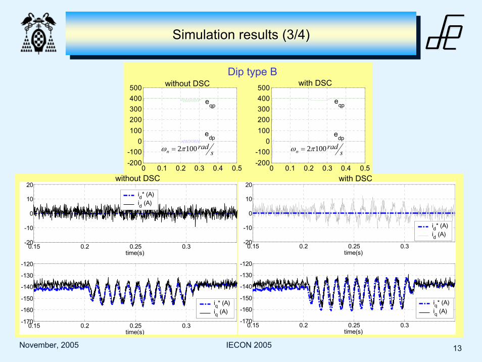
Dip type B. Between 0.2s and 0.3s: 32350ˆ =be
Phase change in the three voltages (balanced system). An increase in the phase of 30º is produced between 0.2s and 0.3s
Harmonics in the grid during the simulation time (0 to 0.5s).
32400ˆˆˆ 111 === cba eee
32
15400ˆˆˆ 555 === cba eee
32
17400ˆˆˆ 777 === cba eee
Frequency jumping in the three phases. Between 0.2s and 0.3s: Hzfff cba 49===
( ) ( )
( ) ( )
( ) ( )32502cos
32400
32502cos
32400
502cos32400
ππ
ππ
π
+=
−=
=
tte
tte
tte
c
b
a

12November, 2005 IECON 2005
Simulation results (2/4)Simulation results (2/4)
Two different studies are carried out:
First study: The SPLL behaviour is analyzed for the following configurations: without DSC, with DSC, fast and slow.
Second study: The behaviour of a VSC connected to the grid with SPLL is tested for the same SPLL configurations.
( )kegr
( )ku∗r
( )1ˆ +kigr
( )kigr
ek
C1−z
G
H
1−z
( )1+kismithr
( )sTr
)(' zCr
gir( )1+∗ kig
r
( )kegr
( )1' +kurgerFeedforward
Discretization of the decoupling term
1−z( )ku∗r
Plant
2
ˆ1
1L
jω−
ZOH
13November, 2005 IECON 2005
0 0.1 0.2 0.3 0.4 0.5-200-100
0100200300400500
time(s)0 0.1 0.2 0.3 0.4 0.5
-200-100
0100200300400500
time(s)
0 0.1 0.2 0.3 0.4 0.5-400
-200
0
200
400
600
time(s)0 0.1 0.2 0.3 0.4 0.5
-200-100
0100200300400500
time(s)
eqp
edp
eqp
edp
eqp
edp
eqp
edp
without DSC with DSC
srad
n 1002πω = srad
n 1002πω =
Dip type B
Simulation results (3/4)Simulation results (3/4)
srad
n 10002πω = srad
n 10002πω =0.15 0.2 0.25 0.3
-20
-10
0
10
20
time(s)
0.15 0.2 0.25 0.3-170
-160
-150
-140
-130
-120
time(s)
id* (A)id (A)
iq* (A)iq (A)
0.15 0.2 0.25 0.3-20
-10
0
10
20
time(s)
0.15 0.2 0.25 0.3-170
-160
-150
-140
-130
-120
time(s)
iq* (A)iq (A)
id* (A)id (A)
without DSC with DSC

14November, 2005 IECON 2005
without DSC with DSCPhase change (30º)
Simulation results (4/4)Simulation results (4/4)
0 0.1 0.2 0.3 0.4 0.5-500
0
500
time(s)0 0.1 0.2 0.3 0.4 0.5
-500
0
500
time(s)
0 0.1 0.2 0.3 0.4 0.5-500
0
500
time(s)0 0.1 0.2 0.3 0.4 0.5
-400
-200
0
200
400
600
time(s)
eqp
edp
eqp
edp
eqp
edp
eqp
edp
srad
n 1002πω = srad
n 1002πω =
srad
n 10002πω = srad
n 10002πω =s
radn 10002πω = s
radn 10002πω =
0.15 0.2 0.25 0.3-40-20
0204060
time(s)
0.15 0.2 0.25 0.3-150-145-140-135-130-125-120
time(s)
id* (A)id (A)
iq* (A)iq (A)
0.15 0.2 0.25 0.3-40-20
0204060
time(s)
0.15 0.2 0.25 0.3-150-145-140-135-130-125-120
time(s)
id* (A)id (A)
without DSC with DSC

15November, 2005 IECON 2005
Conclusion from the simulation resultsConclusion from the simulation results
The SPLL with DSC response is practically independent of the ωn
Table shows the SPLL without DSC rate for obtaining a better behaviour in presence of grid perturbations.
Conclusions of SPLL behaviour
In general, the SPLL without DSC response is better.
Conclusions of the behaviour of theVSCs connected to the grid in function of SPLL
The use of the SPLL with DSC depends on the converter application and the used current controller. The SPLL with DSC is optimal in system with a dual current controller, or in controllers where the feedforward is not the SPLL output but the exact information of the grid signals. Under other circumstances, a SPLL without DSC is a better option.

16November, 2005 IECON 2005
ContentsContents
1. Introduction.
2. SPLL structure.
3. Tuning of SPLL constants.
4. Simulation results.
5. Practical results.
6. Summary and Conclusions.

17November, 2005 IECON 2005
Some photos of the experimental setupSome photos of the experimental setup

18November, 2005 IECON 2005
SPLL SPLL practicalpractical resultsresults andand publicationspublications
egan egbn
Measurements of grid phase voltages
0.3 0.32 0.34 0.36 0.38 0.4-400
-300
-200
-100
0
100
200
300
400
tim e(s)
eganegbnegcn
Acquisition of grid phase voltages
0 0.2 0 .4 0 .6 0 .8 10
100
200
300
400
0 0 .2 0 .4 0 .6 0 .8 1-50
0
50
tim e(s )
e dnege qneg
e dpose qneg
dq components
eqpos
19November, 2005 IECON 2005
ContentsContents
1. Introduction.
2. SPLL structure.
3. Tuning of SPLL constants.
4. Simulation results.
5. Practical results.
6. Summary and Conclusions.

20November, 2005 IECON 2005
Summary and conclusionsSummary and conclusions
A SPLL (software PLL) has been presented for VSCs connected to the grid working as
regenerative circuit. Two different studies have been carried out:
First study: The SPLL behaviour has been analyzed for the following configurations:
without DSC, with DSC, fast and slow.
Second study: The behaviour of a VSC connected to the grid with SPLL has been tested
for the same SPLL configurations.
From this study, it can be deduced that the SPLL with DSC and fast SPLL without DSC are
better, because the dq components do not have ripple in presence of grid perturbations.
From this study, it can be checked that the best SPLL configuration depends on the VSC
current controller.For example, if it is a single dead-beat controller that uses the positive synchronous
reference frame is better a slow SPLL without DSC, because the feedforward action is more
useful.

21November, 2005 IECON 2005
Thank you for your attention!!!
Emilio J. Bueno, Francisco J. Rodríguez, Felipe Espinosa, Santiago Cobreces
Department of Electronics. Alcalá University.28871 Alcalá de Henares, Madrid, Spain
Acknowledgement:This work has been financed by the Spanish administration (CICYT: DPI2002-04555-C04-04).