spill prevention control and countermeasure (spcc) plan
71
SPILL PREVENTION CONTROL AND COUNTERMEASURE (SPCC) PLAN FOR THE Greater Hartford Transit District (GHTD) Operations and Maintenance Facility 148 ROBERTS STREET, EAST HARTFORD CT 06108 June 2017 as amended July 2017 Prepared For: Prepared By: Greater Hartford Transit District Comprehensive Environmental, Inc. One Union Place 1 Hartford Square, Suite 227 Hartford, CT 06103 New Britain, CT 06052
-
Upload
khangminh22 -
Category
Documents
-
view
1 -
download
0
Transcript of spill prevention control and countermeasure (spcc) plan

SPILL PREVENTION CONTROL AND COUNTERMEASURE (SPCC) PLAN
FOR THE
Greater Hartford Transit District (GHTD) Operations and Maintenance Facility
148 ROBERTS STREET, EAST HARTFORD CT 06108
June 2017 as amended July 2017
Prepared For: Prepared By: Greater Hartford Transit District Comprehensive Environmental, Inc. One Union Place 1 Hartford Square, Suite 227 Hartford, CT 06103 New Britain, CT 06052

Spill Prevention Control and Countermeasure Plan GHTD Operations and Maintenance Facility – June 2017 as amended July 2017
TABLE OF CONTENTS 1.0 Introduction and Objective (40 CFR 112.3(a)) ...............................................................1
1.1 SPCC Requirements.................................................................................................1 1.2 Plan Availability (40 CFR 112.3(e) .........................................................................1
2.0 Site Description (40 CFR 112.7(d)(2)) ..............................................................................2 2.1 General .....................................................................................................................2 2.2 Site Activities ...........................................................................................................2
3.0 Materials Handling and Storage (40 CFR 112.1(d)(2) & 112.7(a)(3)(i)) .......................2 3.1 Area #1 – Lube Room ..............................................................................................3 3.2 Area #2 – Diesel Fuel AST ......................................................................................4 3.3 Area #3 – Emergency Generator ..............................................................................4 3.4 Area #4 – Transformer .............................................................................................4 3.5 Area #5 – Fueling Station ........................................................................................5 3.6 Area #6 – Repair Bays .............................................................................................5 3.7 Area #7 – Machine Shop..........................................................................................6
4.0 Previous Spill Events (40 CFR 112.7(a)) ..........................................................................6 5.0 Plan Nonconformance (40 CFR 112.7(a)(2)) ...................................................................6 6.0 Spill Potential (40 CFR 112.7(b)) & Containment Structures (40 CFR 112.7(c))........6 7.0 Proof of Impracticability (40 CFR 112.7(d)) ...................................................................8 8.0 Prevention Conformance (40 CFR 112.7 & 112.8) .........................................................8 8.1 Facility Drainage (40 CFR 112.8(b) & 112.8(c)(9))................................................8 8.2 Oil/Water Separators (40 CFR 112.1(d)(6)) ............................................................9 8.3 Bulk Storage Containers (40 CFR 112.8(c))..........................................................10 8.4 Facility Transfer Operations, Pumping and Facility Process (40 CFR 112.8(d)) ..11 8.5 Facility Loading/Unloading Rack (40 CFR 112.7(h)) ...........................................12 8.6 Inspections, Tests and Records (40 CFR 112.7(e) & 112.8(c)(10)) ......................12 8.7 Brittle Fracture Evaluation Requirements (40 CFR 112.7(i)) ...............................13 8.8 Conformance with State Requirements (40 CFR 112.7(j)) ...................................13 8.9 Qualified Oil-Filled Operational Equipment (40 CFR 112.7(k)) ..........................14 8.10 Security (40 CFR 112.7(g)) ...................................................................................14 8.11 Personnel, Training and Spill Prevention Procedures (40 CFR 112.7(f) ...............14 8.12 Spill Notification & Response Procedures ............................................................16 9.0 SPCC Plan Certifications & Documents........................................................................17 10.0 Regulatory Cross Reference Matrix...............................................................................17 11.0 Task List & Schedule .......................................................................................................18 List of Tables Table 1 – Oil Material Storage.........................................................................................................3 Table 2 – Potential Spill Events .......................................................................................................7 Table 3 – Regulatory Cross-Reference Matrix ..............................................................................17 Table 4 – Task List & Schedule .....................................................................................................19

Spill Prevention Control and Countermeasure Plan GHTD Operations and Maintenance Facility – June 2017 as amended July 2017
List of Figures Figure 1 – Site Locus Map .......................................................................................... End of Report Figure 2 – Exterior Facility Site Plan ......................................................................... End of Report Figure 3 – Interior Facility Site Plan........................................................................... End of Report List of Appendices Appendix A Spill History Documents
• Future Spill Records (reserved) Appendix B Local Permitting Records
• MDC General Permit for the Discharge of Vehicle Maintenance Wastewater to a Sanitary Sewer
Appendix C Oil/Water Separator • Shop Drawing Detail • Inspection Form
Appendix D Inspection Forms and Testing Records • Monthly Inspection Forms
o Area #1 – Lube Room o Area #2 – Exterior Diesel Fuel AST o Area #3 – Exterior Diesel Generator AST o Area #4 – Transformer o Area #5 – Fueling Station o Area #6 and 7 – Repair Bays and Machine Shop
• Inspection Records (reserved) Appendix E Oil Spill Contingency Plan
• Oil Spill Contingency Plan • Written Commitment of Manpower
Appendix F Training Records & Materials • Annual Training Log • Training Records and Materials (reserved)
Appendix G Emergency Information • Reportable Quantities Information • Emergency Contact List • Emergency Spill Response Procedures • Spill Reporting Form • EPA Spill Reporting Fact Sheet
Appendix H Certifications • Facility Certification • Registered Professional Engineer Certification • Owner Review • Certification of Substantial Harm Determination
Appendix I Record of Changes/Plan Amendments

Spill Prevention Control and Countermeasure Plan Page 1 GHTD Operations and Maintenance Facility – June 2017 as amended July 2017
1.0 INTRODUCTION AND OBJECTIVE (40 CFR 112.3(a)) 1.1 SPCC Requirements As stated by the Federal Oil Pollution Prevention Regulation (CFR) part 112, Section 3 (40 CFR part 112.3), owners and operators of onshore and offshore facilities in operation that have discharged or, due to their location, could reasonably be expected to discharge oil in harmful quantities into or upon the navigable waters of the United States or adjoining shorelines, shall prepare a Spill Prevention Control and Countermeasure Plan (SPCC Plan). SPCC Plans are required for facilities that meet one or both of the following criteria:
1. Total aboveground oil storage capacity of more than 1,320 gallons; or 2. Total underground buried storage capacity of more than 42,000 gallons.
If one of these criteria is met, the SPCC plan must address all oil storage, above and underground, in containers equal to or greater than 55 gallons in capacity. SPCC plans establish procedures, methods, and equipment or other requirements for equipment to prevent the discharge of oils. The EPA defines oil as oil of any kind or in any form, including, but not limited to petroleum, fuel oil, sludge, oil refuse and oil mixed with wastes other than dredged spoil. In accordance with the EPA Oil Pollution Prevention regulations promulgated under the Federal Clean Water Act, SPCC plans shall address the following three general areas:
1. Operating procedures that prevent oil spills; 2. Control measures installed to prevent a spill from reaching navigable waters; and 3. Countermeasures to contain, clean up, and mitigate the effects of an oil spill that reaches
navigable waters. This SPCC plan was prepared for the Greater Hartford Transit District (GHTD) Operations and Maintenance Facility (the facility) in East Hartford, CT to comply with Federal Regulation 40 CFR 1121 and in accordance with good engineering practices. The facility has aboveground oil storage capacities in excess of 1,320 gallons, and thereby meets the SPCC criteria outlined above. This plan strictly applies to oil storage as defined by 40 CFR 112 and does not review other hazardous materials used and stored at the facility. This plan has been prepared to complement other existing laws, regulations, rules, standards, policies and procedures related to safety standards, and fire prevention and spill prevention rules.
1.2 Plan Availability (40 CFR 112.3(e)) A copy of the SPCC Plan shall be maintained at the GHTD Operations and Maintenance Facility and will be available to the Environmental Protection Agency (EPA) and the Connecticut Department of Energy and Environmental Protection (DEEP) for review and inspection during normal business hours.
1On July 17, 2002, the Environmental Protection Agency published a final rule that amended the Spill Prevention, Control, and Countermeasure (SPCC) regulations (67 FR 47042). The rule became effective on August 16, 2002 and several amendments have occurred since that time. Most recently on November 5, 2009 (74 FR 58784), EPA signed a final amendment to address additional areas of regulatory reforms. The November 5, 2009 amendments became effective on January 14, 2010, and this SPCC Plan has been developed to meet the requirements of the November 5, 2009 amended SPCC rule.

Spill Prevention Control and Countermeasure Plan Page 1 GHTD Operations and Maintenance Facility – June 2017 as amended July 2017
2.0 SITE DESCRIPTION (40 CFR 112.7(d)(2))
2.1 General The GHTD Operations and Maintenance Facility, located at 148 Roberts Street in East Hartford (see Figure 1), operates as a vehicle storage and maintenance center for transit services offered throughout the Greater Hartford area. The facility is generally used for vehicle storage, vehicle repair and maintenance, liquid petroleum storage, vehicle washing, fueling, and general administrative operations. The facility consists of approximately 4.8 acres (3.9 acres impervious) of area exposed to stormwater and generally includes a large impervious parking area, an enclosed two-story building with an attached roofed fueling area, stormwater BMP, and pervious landscaped perimeter areas and islands. Although owned by GHTD, all facility operations are conducted by GHTD’s subcontractor, First Transit. As such, First Transit is responsible for implementation of all SPCC components, including best management practices, material storage and handling, spill response, reporting, inspections, recordkeeping, training, and other items outlined in this plan.
2.2 Site Activities The site includes a large building surrounded by impervious and pervious parking areas. Exterior areas include a 10,000-gallon diesel aboveground storage tank (AST) used for fueling onsite vehicles and equipment, a 600-gallon diesel-powered generator with an integrated diesel AST, a transformer containing approximately 400-gallons of non-pcb dielectric oil, and general vehicle storage. The building interior generally consists of a lube room storing most of the aboveground petroleum products, numerous repair bays, a vehicle wash bay, covered fueling station, machine shop, storage areas, and various supporting rooms and offices. Exterior and interior facility site plans are shown as Figure 2 and Figure 3, respectively, with the following site features:
• A north arrow and approximate property lines; • Location of existing buildings and structures; • Location and contents of each fixed oil storage container; • Areas where portable containers are located; • Location of transfer stations and connecting pipes; • Drainage patterns and controls; and • Areas exempt from SPCC requirements.
3.0 MATERIALS HANDLING AND STORAGE (40 CFR
112.1(d)(2) & 112.7(a)(3)(i)) The Operations and Maintenance Facility handles and stores oil products as part of vehicle storage, operation, and maintenance activities. The focus of this SPCC Plan is the containment and countermeasures available at the site to prevent a discharge of oil. On-site oil storage and regulated fluid storage (FS) areas area described in Table 1 and discussed in more detail below.

Spill Prevention Control and Countermeasure Plan Page 1 GHTD Operations and Maintenance Facility – June 2017 as amended July 2017
Table 1 – Oil Material Storage
Area Location Material Qty. Storage Container
Capacity (gallons)
Area #1
Lube Room (FS-1) Gear Oil 2 55-gal. drum 110 Lube Room (FS-2) Oil (5W-30) 1 AST 280 Lube Room (FS-3) Oil (15W-40) 1 AST 120 Lube Room (FS-4) Transmission Oil 1 AST 120 Lube Room (FS-9) Used Oil 1 AST 280
Area #2 Exterior, near northwest corner of building Diesel Fuel 1 AST 10,000
Area #3 Exterior, near northwest corner of building Diesel Fuel 1 AST (Integrated
tank) 600
Area #4 Exterior, near southwest corner of building
Dielectric Oil (non-PCB) 1 Transformer 400
(approx.) Area #5 Fueling station N/A (see Area #2) Area #6 Repair Bays N/A (see Area #1) Area #7 Machine Shop N/A (see Area #1)
Total oil storage capacity: 11,910 gallons
3.1 Area #1 – Lube Room The Lube Room is located near the northwest corner of the building and used to store multiple ASTs and 55-gallon drums. Product is pumped using compressed air to reel banks throughout the facility (see Figure 3) via piping and hoses (see Area #6). The following regulated materials are stored within this area:
• 55-gallon drums of gear oil (up to 2 drums) (FS-1); • 280-gallon AST of 5W-30 engine oil (FS-2); • 120-gallon AST of 15W-40 engine oil (FS-3); • 120-gallon AST of automatic transmission fluid (FS-4); and • 280-gallon AST of used engine oil (FS-9).
In addition, the following materials are not regulated under SPCC regulations, as they are not oil-containing products, however are included below and shown on the attached figure for reference:
• 120-gallon AST of windshield washer fluid (FS-5); • 55-gallon drum of engine coolant concentrate (FS-6); • 120-gallon AST of engine coolant mix (FS-7); • 55-gallon drum of grease (FS-8); • 120-gallon AST of used coolant (FS-10); and • 1,000-gallon AST of diesel exhaust fluid (DEF).
All ASTs containing both regulated and unregulated materials are double-walled tanks with 110% capacity, equipped with integrated diaphragm tank pumping systems. Tanks are equipped with the following safeguards:
• Overfill Prevention Valve (Morris Bros Co. #9095A-0200AV); • Interstitial Leak Detection Sensor (Veeder Root #794-390-420); • Magnetostrictive Inventory Probe (Veeder Root #846391-3);
Spill Prevention Control and Countermeasure Plan Page 1 GHTD Operations and Maintenance Facility – June 2017 as amended July 2017
• Mechanical Tank Gauge (Scully Signal Company #03113); • Bleed type air shut-off valve (Graco #110225); and • Air Guard Over Run Control (Graco #224040).
Inventory probes and interstitial leak sensors are connected to a web-based Leak Detection Monitor Panel (Veeder Root #TLS-450) which constantly monitors for potential problems and sounds an alarm, should an adverse condition be detected. 55-gallon drums containing both regulated and unregulated materials may be set on spill pallets as a best management practice while in the Lube Room, however, are not required due to the presence of an automated spill control barrier encompassing the Lube Room. Should any of the 55-gallon drums be moved out of this room, these drums should be placed on spill pallets capable of capturing 110% of the volume (61 gallons). Note that as no product is added to any 55-gallon drums (product is only removed), overfill alarms are not required or in place.
3.2 Area #2 – Diesel Fuel AST A 10,000-gallon diesel fuel tank is located outside near the northwest corner of the building and is connected to a pair of fuel pumps located within the Fueling Station (see Area #5). This tank is double-walled, located on a concrete pad, and surrounded by steel bollards to protect against a potential vehicle crash. This tank is equipped with the following safeguards:
• Emergency shut-off switch; • Fill spill container; • Overfill Prevention Valve (OPW #175); • Interstitial Leak Detection Sensor (Veeder Root #794-390-420); • Magnetostrictive Inventory Probe (Veeder Root #846391-3); • Mechanical Line Leak Detector (Red Jacket #FXV); and • Thermal Pressure Relief Valve (OPW #82RV).
Inventory probes and interstitial leak sensors are connected to a web-based Leak Detection Monitor Panel (Veeder Root #TLS-450) which constantly monitors for potential problems and sounds an alarm, should an adverse condition be detected. Note that this tank was relocated from the previous facility. Prior to being relocated, the tank was pressure tested both before being relocated and retested after installation to comply with requirements for integrity and leak testing under 112.8(c)(6).
3.3 Area #3 – Emergency Generator A 600-gallon diesel fuel tank located outside near the northwest corner of the building is integrated into a 600-kW emergency generator used to power the facility in the event of a power outage. This tank is double-walled, located on a concrete pad, and surrounded by steel bollards to protect against a potential vehicle crash.
3.4 Area #4 – Transformer A 400-gallon (approximate) transformer filled with dielectric, non-PCB oil is located outside near the southwest corner of the building on a concrete pad and surrounded by steel bollards to

Spill Prevention Control and Countermeasure Plan Page 1 GHTD Operations and Maintenance Facility – June 2017 as amended July 2017
protect against a potential vehicle crash. This AST is considered oil-filled operational equipment and thus is not considered a bulk storage container and is not subject to the same secondary containment requirements as a standard AST (see Section 8.9).
3.5 Area #5 – Fueling Station The Fueling Station has two lanes with diesel fuel pumps, one per lane, connected to the diesel fuel AST located in Area #2 via 2” piping. Fuel pumps are equipped with the following safeguards:
• Emergency shutoff switch to disable fuel system; • Fuel Management System Controller (Fleetwatch Remote Island Head #3000R); • Pressure Activated Automatic Shutoff Nozzles (OPW #11B); • Flow Limiter (OPW #44-0044); • Hose Breakaway (OPW #66RB); and • Emergency Shear Valve (OPW 10).
Fuel is dispensed via the Fuel Management System Controller to track all fuel dispensing. Remaining safeguards on the diesel AST are outlined under Area #2. This area also has several dispensing nozzles connected to reels for “topping off” of fluids such as engine oil, transmission fluid, coolant, windshield washer fluid, and diesel exhaust fluid from ASTs and drums located in Area #1. Products stored in Area #1 are connected via steel piping varying from ¾” to 1 ½” in diameter to hose reel banks located in this area. Hose reels are generally located 14-feet off of the garage floor, with nozzles located a maximum of 6-feet off of the garage floor. Reels dispensing regulated product, including engine oil and automatic transmission fluid have a solenoid valve and pulse transmitter connected to the fuel/fluid management system to record material quantities dispensed. Reels also have a manual fluid shut-off valve located above each reel. Note that this area is only for distributing virgin product, as all maintenance operations are conducted in the Repair Bays (Area #6).
3.6 Area #6 – Repair Bays The Repair Bays include a Tire Bay, 3 Running Repair bays, and 1 Gasoline Repair Bay. All repair bays are used for general repair and maintenance of motor vehicles owned by GHTD. Used product (i.e. engine oil, coolant, etc.) are drained into portable, wheeled containers during routine operations before being transported to the Machine Shop (Area #7) to transport product to ASTs in Area #1. The multiple ASTs and 55-gallon drums located within the Lube Room (Area #1) containing regulated product are connected via steel piping varying from ¾” to 1 ½” in diameter to hose reel banks located throughout the facility. Hose reels are generally located 14-feet off of the garage floor, with nozzles located a maximum of 6-feet off of the garage floor. Reels dispensing regulated product, including engine oil and automatic transmission fluid have a solenoid valve and pulse transmitter connected to the fuel/fluid management system to record material quantities dispensed. Reels also have a manual fluid shut-off valve located above each reel.

Spill Prevention Control and Countermeasure Plan Page 1 GHTD Operations and Maintenance Facility – June 2017 as amended July 2017
3.7 Area #7 – Machine Shop The Machine Shop has two pumps for transferring used coolant and used oil to the 120-gallon AST and 280-gallon AST, respectively, located in the Lube Room. Personnel performing maintenance and repair operations in the Repair Bays (Area #6) drain used product into wheeled drain pans approximately 10 to 20-gallons in size, wheel these containers to the Machine Shop, and pump used product using the appropriate pump. 4.0 PREVIOUS SPILL EVENTS (40 CFR 112.7(a)) The SPCC Plan must include a description of any spill events that occurred within the past three years, including any corrective actions taken and any plans for preventing a recurrence. As of the date of this plan, no spills have occurred within the past three years at this facility. Appendix A contains a place reserved for records related to future spill events that may occur at the facility.
5.0 PLAN NONCONFORMANCE (40 CFR 112.7(a)(2)) The contents of this plan discuss conformance with all applicable sections of 40 CFR 112.7 and 112.8 (Sections 6.0 through 10.0 of this Plan), as required by 40 CFR 112.7(a). 6.0 SPILL POTENTIAL (40 CFR 112.7(b)) & CONTAINMENT
STRUCTURES (40 CFR 112.7(c)) The GHTD Operations and Maintenance Facility was evaluated to determine where there is a reasonable potential for equipment failure, which could result in a potential release of oil. Each location where oil products are stored was evaluated for predicted direction and rate of flow as well as the maximum quantity of oil that could be discharged as a result of each major type of failure. Additionally, under the SPCC regulation requirements, the facility was evaluated for appropriate containment and diversionary structures or equipment, which can prevent discharged oil from reaching navigable watercourses. Each area identified as having a reasonable potential for a release of oil was inspected to determine if one of the following preventive systems or its equivalent was available:
• Dikes, curbing, berms or retaining walls sufficiently impervious to contain spilled oil; • Sumps and collection systems; • Culverts, gutters or other drainage systems; • Weirs, booms or other barriers; • Spill diversion ponds or retention ponds; and/or • Sorbent materials.
A summary of potential spill events is provided in Table 2 with a more detailed discussion of protective measures below for each on-site oil storage area.

Spill Prevention Control and Countermeasure Plan Page 7 GHTD Operations and Maintenance Facility – June 2017, as amended July 2017
Table 2 – Potential Spill Events
Area Location Potential Source
Material Stored Potential Release (estimated) Rate of Flow (estimated) Direction of Spill Protective Measures
Interior Storage
Area #1 – Lube Room
Southeast corner, gear oil
drums
55-gallon drum
(up to 2) Gear Oil
Rupture/leak: up to 55 gal. Overfill: up to 1 gal. Line Leak: up to 1 gal.
Rupture/leak: <5 gal/min. Overfill: <1 gal/min. Line Leak: <1 gal/min
Contained within spill pallets. Overflow will stay within room and contained via automated spill control barrier. In the event of a failure of the automated spill barrier, will flow south to nearest catch basin and then east to Outfall 2.
• Spill pallets • Inside building • Automated spill barrier
Western wall, engine oil AST
280-gallon AST
Engine Oil (5W-30)
Rupture/leak: up to 280 gal. Overfill: up to 1 gal. Line Leak: up to 1 gal.
Rupture/leak: <5 gal/min. Overfill: <1 gal/min. Line Leak: <1 gal/min.
Contained within room via automated spill control barrier. In the event of a failure of the automated spill barrier, will flow south to nearest catch basin and then east to Outfall 2.
• Double-walled tank • Inside building • Automated spill barrier • Overfill Prevention Valve • Interstitial Leak Detection Sensor • Magnetostrictive Inventory Probe • Mechanical Tank Gauge • Bleed type air shut-off valve • Air Guard Over Run Control
Northwest corner, engine
oil AST
120-gallon AST
Engine Oil (15W-40)
Rupture/leak: up to 120 gal. Overfill: up to 1 gal. Line Leak: up to 1 gal.
Rupture/leak: <5 gal/min. Overfill: <1 gal/min. Line Leak: <1 gal/min.
Western wall, transmission oil
AST
120-gallon AST
Transmission Oil
Rupture/leak: up to 120 gal. Overfill: up to 1 gal. Line Leak: up to 1 gal.
Rupture/leak: <5 gal/min. Overfill: <1 gal/min. Line Leak: <1 gal/min.
Southwest corner, oil AST
280-gallon AST Used Oil
Rupture/leak: up to 280 gal. Overfill: up to 1 gal. Line Leak: up to 1 gal.
Rupture/leak: <5 gal/min. Overfill: <1 gal/min. Line Leak: <1 gal/min.
Area #2 – Diesel Fuel AST
Exterior, near northwest corner of building
10,000-gallon AST Diesel Fuel
Rupture/leak: up to 10,000 gal. Overfill: up to 100 gal. Line Leak: up to 5-10 gal.
Rupture/leak: <5 gal/min. Overfill: <1 gal/min. Line Leak: <1 gal/min
Contained within secondary containment. Overflows or bypass to concrete pad, then to surrounding stone, and infiltrate into the ground; large flows to northeastern catch basin CB-7, to stormwater BMP, then to Outfall 1.
• Emergency shut-off switch • Fill spill container • Overfill Prevention Valve • Interstitial Leak Detection Sensor • Magnetostrictive Inventory Probe • Mechanical Line Leak Detector • Thermal Pressure Relief Valve
Area #3 – Emergency Generator
Exterior, near northwest corner of building
600-gallon AST Diesel Fuel Rupture/leak: up to 600 gal.
Overfill: up to 5-10 gal. Rupture/leak: <5 gal/min. Overfill: <1 gal/min.
Contained within secondary containment. Overflows or bypass to concrete pad, then to surrounding stone, and infiltrate into the ground; large flows to northeastern catch basin CB-7, to stormwater BMP, then to Outfall 1.
• Double-walled tank • Steel bollards
Area #4 – Transformer
Exterior, near southwest
building corner
400-gallon Transformer
(approx.)
Dielectric Oil (non-PCB) Rupture/leak: up to 400 gal. Rupture/leak: <5 gal/min.
To concrete pad, then to surrounding stone, and infiltrate into the ground; large flows to northeastern catch basin CB-3 then to Outfall 2.
• Steel bollards
Area #5 – Fueling Station
Northwest corner of the
building See Area #2 Diesel Fuel Overfill: up to 1 gal.
Line Leak: up to 1 gal. Overfill: <1 gal/min. Line Leak: <1 gal/min
To floor drains and to oil/water separator at the rear of the building. Large spills could overflow the oil/water separator and would go to the municipal sewer system.
• Emergency shutoff switch to disable fuel system • Fuel Management System Controller • Pressure Activated Automatic Shutoff Nozzles • Flow Limiter • Hose Breakaway • Emergency Shear Valve • Oil/water separator
Note: For Areas #6 and Area #7 sources, release volumes, and rates, see Area #1. Spill sin these areas would go to floor drains and to oil/water separator at the rear of the building. Large spills could overflow the oil/water separator and would go to the municipal sewer system.

Spill Prevention Control and Countermeasure Plan Page 10 GHTD Operations and Maintenance Facility – June 2017, as amended July 2017
7.0 PROOF OF IMPRACTICABILITY (40 CFR 112.7(d)) According to the SPCC regulations, if the installation of structures and equipment listed in 40 CFR 112.7(c) to prevent discharged oil from reaching navigable waters is not practical, the owner and operator shall clearly demonstrate such impracticability and provide additional oil spill contingency measures. There are no obstacles preventing the installation of structures and equipment at the GHTD Operations and Maintenance Facility to prevent discharged oil from reaching navigable waters. 8.0 PREVENTION CONFORMANCE (40 CFR 112.7 & 112.8) In addition to the minimum prevention standards listed under 40 CFR 112.7(c) and requirements for onshore oil facilities (40 CFR 112.8); the SPCC regulations require a discussion of conformance with the following applicable guidelines, or other effective control measures:
1. Facility Drainage 2. Oil/Water Separators 3. Bulk Storage Containers 4. Facility Transfer Operations, Pumping and Facility Process 5. Facility Tank Car and Tank Truck Loading/Unloading Rack 6. Inspections, Tests and Records 7. Brittle Fracture Evaluation Requirements 8. Conformance with State Requirements 9. Qualified oil-filled electrical equipment 10. Security 11. Personnel, Training and Discharge (Spill) Prevention Procedures 12. Spill Notification & Response Procedures
8.1 Facility Drainage (40 CFR 112.8(b) & (c)(9)) SPCC regulations require facilities to have on-site drainage systems designed to prevent a discharge into navigable waters or adjoining shorelines of the United States as described in 40 CFR 112.1(b) in the event a spill occurs due to equipment failure or human error. Building Interior Indoor sources include the Lube Room (Area #1), Fueling Station (Area #5), Repair Bays (Area #6), and Machine Shop (Area #7). The Lube Room (Area #1) is equipped with an automated spill control system (Denios #R14-0312) whereby the presence of spills or liquids will automatically trigger a 12-inch high spill barrier that contains spills within the room and inside the building. When not engaged, the barrier is at a level even with the floor to facilitate easy maneuvering of drums or other materials into and out of the room.

Spill Prevention Control and Countermeasure Plan Page 10 GHTD Operations and Maintenance Facility – June 2017, as amended July 2017
Spills or incidental drips from precipitation or snow on vehicles within remaining areas (Fueling Station (Area #5), Repair Bays (Area #6), and Machine Shop (Area #7)) are collected in a series of floor drains throughout the building and ultimately to an oil/water separator located north of the building. This structure is connected to the municipal sewer system and has obtained a certification from The Metropolitan District (MDC) General Permit for the Discharge of Vehicle Maintenance Wastewater to a Sanitary Sewer as provided in Appendix B. Site Exterior The site has been designed with extensive structural best management practices for controlling and managing stormwater runoff, including the following:
• Catch basins with deep sumps and oil/water separator hood; • Sediment forebay for pretreatment; • Detention basin with outlet control structure to manage stormwater flows offsite; and • Pervious pavement with underdrain system.
Sources within the northern area include the 10,000-gallon diesel AST (Area #2) and 600-gallon emergency generator (Area #3). Stormwater from this area is collected in a series of deep sump catch basins equipped with oil/water separator hoods before being conveyed into the sediment forebay and detention pond with attached underground storage area located at the northeast corner of the parking lot. This stormwater BMP is designed to first allow sediment to settle out in the sediment forebay to facilitate easier maintenance. Stormwater then flows into a detention pond, with water levels controlled by an outlet control device that regulates stormwater flows in order to reduce peak flow rates and volumes. Stormwater is allowed to pond within the basin and within an underground storage system located immediately adjacent under the northern parking lot area before ultimately being released to the wetland area north of the site via Outfall 1 towards the Hockanum River, equipped with riprap for erosion control protection. This outfall does not discharge directly to the river, instead releasing approximately 500 feet short of the river. Sources within the southern area include the 400-gallon (approximate) transformer (Area #4), and is considered oil-filled operational equipment. Stormwater from the southern portion of the site is collected in a series of deep sump catch basins equipped with oil/water separator hoods, as well as via an underdrain installed below a section of porous pavement. The system conveys stormwater into a catch basin to the east of the building which then outlets northeasterly via Outfall 2 and into the wooded area east of the site. In addition, this facility has a Stormwater Pollution Prevention Plan (SWPPP) prepared as required for facilities with SIC Code 9199. Additional inspections of the drainage system and industrial activity areas are performed as outlined in the SWPPP.
8.2 Oil/Water Separators (40 CFR 112.1(d)(6)) As discussed above and shown on Figure 2, an oil/water separator is located north of the Operations and Maintenance Facility to provide additional protection against the migration of an indoor spill. All floor drains within the building are connected to the oil/water separator, which is connected to the municipal sewer system. As outlined in 40 CFR 112.1(d)(6), oil/water separators are not subject to the SPCC requirements and do not count towards the facility’s oil

Spill Prevention Control and Countermeasure Plan Page 10 GHTD Operations and Maintenance Facility – June 2017, as amended July 2017
storage capacity since they are not petroleum storage containers and are not used to meet the requirements of 40 CFR 112. The oil/water separator provides a contingency measure in the event of a spill with indoor areas such as the Repair Bays. However, the oil/water separator and the contributing drainage or floor drain system require routine inspection and maintenance to ensure proper function, as outlined below:
• Visually inspect oil/water separators and floor drains every six months to evaluate maintenance requirements; inspection frequency may be modified based on inspection results;
• Visually inspect vehicle wash bay and associated components per manufacturer recommendations, or at least every six months;
• Open separator/basin, probe sediment depth and determine oil thickness (sheen or uniform layer);
• Vacuum oil/water separator to remove oil and solids; dispose properly; and • Visually inspect condition of foundation slab and floor drains to ensure no cracks or
damage are present. In addition, all exterior catch basins are equipped with oil/water separator “hoods” that help reduce the potential and amount of oil and other floatables that would flow uncontrolled from within each structure. Although called oil/water separators, these devices function differently than a standard actual oil/water separator outlined above and thus are used for supplemental stormwater treatment only. These devices are inspected as part of routine facility operations. A detail of the oil/water separator and optional inspection form to be completed every six months are provided in Appendix C.
8.3 Bulk Storage Containers (40 CFR 112.8(c)) SPCC regulations state that the material and construction of bulk storage containers used for oil storage must be compatible with oil products and must have some form of secondary containment should a spill occur. In accordance with the SPCC regulations, all oil storage containers are constructed with materials designed to contain oil products. Additionally, secondary containment systems are in place for bulk storage containers. See Section 3.0 for additional details on oil containers and secondary containment measures. Note that the transformer (Area #4) is considered oil-filled operational equipment and thus is not considered a bulk storage container as outlined in Section 8.9. UST Cathodic Protection – 40 CFR 112.8(c)(4) There are no underground storage tanks in use on this property. Partially Buried Tank Cathodic Protection – 40 CFR 112.8(c)(5) There are no partially buried storage tanks in use on this property. Heating Coils – 40 CFR 112.8(c)(7) There are no internal heating coils in use on this property.

Spill Prevention Control and Countermeasure Plan Page 10 GHTD Operations and Maintenance Facility – June 2017, as amended July 2017
High Liquid Level – 40 CFR 112.8(c)(8) ASTs located within the Lube Room (Area #1) and the 10,000-gallon diesel tank (Area #2) are equipped with high level alarms connected to a Veeder Root web-based Leak Detection Monitor Panel (Veeder Root #TLS-450) capable of alerting personnel when a tank approaches capacity. These ASTs are also equipped with an Overfill Prevention Valve (OPW #175) which automatically stop the flow of product when it is nearing capacity. The Emergency Generator (Area #3) is equipped with a fuel tank derangement alarm and high-level fuel supply alarm. Personnel are regularly present during filling of all tanks and containers.
8.4 Facility Transfer Operations, Pumping and Facility Process (40 CFR 112.8(d)) SPCC regulations require that fuel transfer operations and piping adhere to good engineering practices that include sufficient transfer line protection and routine inspections. Aboveground valves, piping, and appurtenances must be regularly inspected. Inspections must include general condition of items such as joints, pipes, surfaces, etc. Inspections are detailed further in Section 8.6. Fuel/Oil Deliveries The external 10,000-gallon diesel AST and the internal ASTs are filled by fuel delivery companies on an as-needed basis. AST filling procedures consist of removing the cover from the fill spill container to expose the fill port. The AST is also equipped with a number of alarms, including a high level alarm and overfill prevention valve. Per discussions with Site personnel, the 10,000-gallon diesel AST is refilled approximately every 9 days with 7,000 gallons of diesel fuel. Site personnel monitor fuel levels during routine operations and notify the appropriate fuel delivery company when tank levels are low. Annual fuel consumption is estimated at approximately 280,000 gallons of diesel for this tank. The emergency generator diesel AST is only used during emergencies, and thus is filled infrequently on an as-needed basis. Indoor ASTs within the Lube Room are also filled as needed. GHTD personnel are always in attendance during fuel deliveries to unlock tanks as needed and supervise the process in the event of a spill. Staff regularly implement the following spill prevention measures for fuel/oil deliveries:
• Check fuel/oil delivery area and remove any stored objects or foreign debris that may hinder delivery operations;
• Ensure fill port is in good working order; • Have spill response materials on hand and accessible near fuel transfer equipment; • Make sure vehicle is attended during loading/unloading process; and • Inspect delivery area and fill port area for any leaks or minor spills after driver leaves the
loading/unloading area and cleanup any oil found with spill absorbent materials. Fuel Transfer Lines Fuel transfer lines are present on-site from the 10,000-gallon diesel AST which connect to two fuel pumps each located on separate islands on the north side of the facility within the Fueling Station (Area #5). Fuel is dispensed by site personnel via the Fuel Management System

Spill Prevention Control and Countermeasure Plan Page 10 GHTD Operations and Maintenance Facility – June 2017, as amended July 2017
Controller to track all fuel dispensing. Both fuel pumps are manually operated and equipped with a pressure activated automatic shutoff nozzle which will discontinue fueling once tanks are filled. Pumps are also equipped with hose breakaways and emergency shear valves which will shutoff the fuel supply in the event of damage to the fuel transfer line.
8.5 Facility Loading/Unloading Rack (40 CFR 112.7(h)) This facility does not have a tank car or truck loading/unloading rack; therefore, the requirements of 40 CFR 112.7(h) do not apply.
8.6 Inspections, Tests and Records (40 CFR 112.7(e) & 112.8(c)(10)) In accordance with SPCC regulations, each of the areas containing oil must be inspected routinely according to this plan and records must be kept on file for a minimum of three years. As part of routine facility operations, personnel visually inspect the ASTs, drums, monitoring equipment, and fuel pumps on a daily basis. Routine, informal (unwritten) inspections shall be conducted at least weekly to ensure that the oil storage areas, containers, tanks and associated transfer lines are maintained and free from hazards, spills, visible leaks, or deterioration. During these inspections, any evidence of a spill condition (i.e., leaking lines, cracks) or potential spill shall be reported and fixed immediately. SPCC inspections of all ASTs, drums, and handling and storage areas are conducted on a monthly basis using online forms via EiOS software via the Strata Environmental website. Inspections generally include visual inspections to ensure that the oil storage areas, containers, tanks and associated transfer lines are maintained and free from hazards, spills, visible leaks, or deterioration. During these inspections, any evidence of a spill condition (i.e., leaking lines, cracks) or potential spill shall be reported and fixed immediately. Copies of the inspection forms are provided in Appendix D. Inspection sheets shall be signed by the inspector or supervisor and will be made part of this SPCC Plan to fulfill inspection requirements. Inspection records shall be maintained for a minimum period of three years. Integrity Testing – 40 CFR 112.8(c)(6) SPCC regulations also require that aboveground storage tanks be tested for integrity on a regular schedule using a testing technique other than visual inspection, in accordance with standard industry practices. Acceptable testing methods are outlined in the American Petroleum Institute (API) Standard 653, “Tank Inspection, Repair, Alteration and Reconstruction” and API Standard 650. In accordance with API 653, ASTs at the facility must be integrity tested every 10 years by a certified petroleum equipment specialist. This procedure includes draining and cleaning the ASTs and performing any repairs or painting once the inspection is completed. A qualified inspector must perform the integrity tests. The schedule for future integrity testing is outlined in Table 4 (Section 11.0). Test records need to be maintained with the inspection sheets in Appendix D.

Spill Prevention Control and Countermeasure Plan Page 10 GHTD Operations and Maintenance Facility – June 2017, as amended July 2017
Note that the Diesel Fuel AST (Area #2) was recently relocated from the previous facility. Prior to being relocated, the tank was pressure tested both before being relocated and retested after installation to comply with this requirement.
8.7 Brittle Fracture Evaluation Requirements (40 CFR 112.7(i)) Field-constructed ASTs or existing ASTs that undergo a repair, alteration, reconstruction or change in service that might affect the risk of a discharge or failure due to brittle fracture or other catastrophe must be evaluated for such risk. The standard industry methods for brittle fracture evaluation can be found in the American Petroleum Institute (API) Standard 653, “Tank Inspection, Repair, Alteration and Reconstruction”; and API Recommended Practice 920, “Prevention of Brittle Fracture of Pressure Vessels”. With the exception of the Diesel Fuel AST (Area #1), ASTs at the facility are newly manufactured tanks and have not undergone any structural changes since installation; therefore, brittle fracture evaluation is not required for these tanks. Prior to being relocated, the Diesel Fuel AST was pressure tested both before being relocated and retested after installation to comply with this requirement. The GHTD must ensure the requirements at 40 CFR 112.7(i) are fulfilled if additional tanks undergo significant repairs or alterations.
8.8 Conformance with State Requirements (40 CFR 112.7(j)) The State of Connecticut does not directly regulate SPCC Plans and does not have more stringent rules or guidelines for spill prevention. Connecticut DEEP does require that owners or operators of new emergency engines, such as emergency generators, either obtain a permit or meet other obligations when potential emissions of any individual air pollutants are equal to or greater than 15 tons per year. The proposed emergency generator onsite noted under Area #3 is powered by a Cummins Diesel Generator Model DQCA engine exceeding 15 tons per year of emissions, and must do the following to meet the conditions of RCSA Section 22a-174-3b under a permit exemption:
• Use fuel with a sulfur content that does not exceed that of federal motor vehicle diesel fuel, which is 0.0015% by weight;
• Limit hours of operation to 300 hours in any twelve consecutive months; and • Maintain records of the hours of operation for each month and each twelve-month rolling
aggregate. Maintain records of fuel purchases. In fulfillment of the above conditions, all fuel purchased is low-sulfur diesel fuel containing less than 0.0015% sulfur by weight. The diesel generator currently runs automatically approximately once per week for a period of one-hour, totaling approximately 50 hours per year which is significantly less than 300-hours in any twelve consecutive months. This allows for approximately 250-hours per year of emergency operation, equivalent to approximately 10 days of emergency power. This is anticipated to be more than adequate for even an extreme event. Staff also maintain records on the hours of operation for each month, along with records of fuel purchases to meet permit exemptions outlined above. The generator also automatically records hours operated.

Spill Prevention Control and Countermeasure Plan Page 10 GHTD Operations and Maintenance Facility – June 2017, as amended July 2017
Note that an alternate option of limiting potential emissions under RCSA Section 22a-174-3c is not feasible at this site, as it in part restricts total fuel purchases for the entire facility to less than 21,000 gallons in any calendar year. As this facility fuels buses with diesel fuel, total annual consumption exceeds the 21,000-gallon limit.
8.9 Qualified Oil-Filled Operational Equipment (40 CFR 112.7(k)) In accordance with 40 CFR 112.7(k)(2), GHTD is required to develop an Oil Spill Contingency Plan to meet the requirements of 40 CFR 109 for Area #4 – Transformer due to the lack of secondary containment. The purpose of this plan is to establish procedures to insure timely, efficient, coordinated and effective action to minimize damage resulting from oil discharges from the large transformer. An Oil Spill Contingency Plan was developed in conjunction with this SPCC Plan and is appended to this Plan as Appendix E. A written commitment of manpower, equipment, and materials required to expeditiously control and remove harmful quantities of oil that may be discharges is provided in Appendix E.
8.10 Security (40 CFR 112.7(g)) The entire site is enclosed in a perimeter chain-link fence with locked gates that restrict access to the area when closed. The site is also equipped with adequate lighting to aid in the discovery of discharges occurring during dark hours and discourage vandalism. Access to indoor storage areas are restricted to site personnel only. Bulk storage ASTs are also equipped with a remote monitoring system capable of alerting facility personnel in the event of an emergency or spill. Security measures for the on-site tanks and fuel dispensing equipment provide sufficient security and equivalent environmental protection in accordance with 40 CFR 112.7(a)(2).
8.11 Personnel, Training and Spill Prevention Procedures (40 CFR 112.7(f))
Employees responsible for the management and operation of the facility and property must provide training of site personnel in the operation and maintenance of equipment to prevent oil discharges; discharge procedure protocols; applicable pollution control laws, rules and regulations; general facility operations; and the contents of the facility SPCC Plan. SPCC Plan Coordinators (40 CFR 112.7(f)(2)) The following individuals are responsible for implementation of the SPCC plan, proper training of employees, and notifications:
Matthew Lontz, Maintenance Manager for First Transit Responsibilities of the SPCC Plan Coordinators Include:
• Maintain spill control containment equipment and materials; • Conduct personnel training or ensure training is completed; • Ensure compliance with plan and applicable regulations; • Update SPCC Plan, as required (see Section 9.0); • Conduct or supervise visual inspections & review results; • Ensure record keeping of inspection logs; • Appoint trained personnel to supervise oil deliveries; and

Spill Prevention Control and Countermeasure Plan Page 10 GHTD Operations and Maintenance Facility – June 2017, as amended July 2017
• Notify appropriate officials of any spill events. Spill Management Training Personnel shall be trained annually in the following general spill management procedures for oil spills that may occur at the facility:
• Conducting visual inspections of the facility; • Record keeping procedures; • Spill containment procedures (discussed below) and use of spill control equipment and
materials; • Emergency reporting requirements; • De-briefing of any spill events or failures, malfunctioning equipment, or precautionary
measures taken; • SPCC plan requirements; and • Responsible management individuals and communication channels.
To fulfill the training requirement, GHTD and First Transit completes online courses taken through a certified training center. These online courses will train employees specifically for the contents and requirements of the SPCC Plan discussed above as well as site-specific equipment, operations and site features at the Operations and Maintenance Facility. Additionally, the in-house training program will address reporting, record keeping and management requirements. A record of annual training sessions shall be incorporated into the SPCC Plan including the following information:
• Date and time of training session; • Instructor(s) and attendees; • Topics covered during training session; • Instructional aids and handouts provided; and • Items and questions requiring follow-up by SPCC coordinator.
Records shall include a copy of the training program used and a signed log sheet for employees completing the program provided in Appendix F. All training records shall be maintained in Appendix F. Spill Containment Procedures Potential spill information, response procedures, inspection requirements and maintenance BMPs are provided in Appendix G. As a general guideline, all employees shall be familiar with and utilize the following procedures, as appropriate and feasible, in the event of a spill:
• Safety first – Assess the spill area for safety conditions; • Evaluate the need for medical, fire safety, police, and evacuation; • Call for help – Notify the SPCC Coordinator and emergency contacts (as required); • Stop the source of the spill – if you can safely; • Apply absorbent pads, booms, or other material to the spill area to immediately contain
the oil spill - if you can safely; • Place additional pads or booms in the direction of flow as needed; • Notify appropriate agencies of release (if necessary, see below);

Spill Prevention Control and Countermeasure Plan Page 10 GHTD Operations and Maintenance Facility – June 2017, as amended July 2017
• Contact the East Hartford Fire Department (if necessary); • Document spill for inclusion in SPCC Plan (include corrective actions taken and plans to
prevent recurrence). Any person discovering a release of hazardous substance into the air, water, soil, or groundwater is to immediately report the event to the SPCC Plan Coordinator who will provide initial response to operating situations related to the spill (operation changes, spill containment and control). The reporting person must identify him or herself, indicate the type of accident, location, materials included, and extent of any injuries. Depending on the situation, the SPCC Plan Coordinator will notify local emergency personnel (fire department, first aid, hospital, etc.) as required. Once the spill situation has been established, the SPCC Plan Coordinator must make a determination as to whether the facility and/or surrounding area should be evacuated and to what extent. The phone numbers for emergency individuals and local and state agencies are posted conspicuously throughout the facility and are located in Appendix G. To prevent further pollution, the spill source shall be determined and additional spillage curtailed, if it is possible and safe to do so. In no case should any person attempt to stop a spill without proper equipment or personnel backup. The SPCC Plan Coordinator shall keep facility staff informed of the situation during the emergency. If any portion of the facility or all of the facility must be shut down, the emergency response coordinator will inform the necessary authorities.
8.12 Spill Notification & Response Procedures A release of oil of any amount is required to be immediately reported to DEEP. A spill reporting fact sheet is provided in Appendix G, along with a list of emergency phone numbers. This includes the Connecticut DEEP notification number that must be called in the event of a spill. The National Response Center must be notified of any oil release violating state water quality standards, causes a film or sheen on the water’s surface, or leaves sludge or emulsion beneath the surface. Notifications should be reported immediately, or within 2 hours of obtaining knowledge of the release. The EPA Regional Administrator must be notified of any oil discharge of greater than 1,000 gallons in a single discharge or more than 42 gallons in each of two discharges within a 12-month period. The Agency may require a spill report within 60 days from the time of the spill. Oil spills that are not to navigable waters or adjoining shorelines need not be reported. This information is outlined in more detail in Appendix G along with the emergency number for the Agency. The list of emergency phone numbers should be posted at each phone in both facilities. A spill reporting fact sheet has been provided as part of Appendix G. As required by 40 CFR 112.7(a)(4), information and procedures for reporting a spill must be provided in the SPCC Plan to enable someone reporting a spill to provide the appropriate information. This information is provided in an easy-to-read format in Appendix G along with
Spill Prevention Control and Countermeasure Plan Page 10 GHTD Operations and Maintenance Facility – June 2017, as amended July 2017
spill response procedures that can be easily followed during an emergency, as required by 40 CFR 112.7(a)(5). 9.0 SPCC PLAN CERTIFICATIONS AND DOCUMENTS Appendix H provides a summary of information that certifies the completion of a SPCC Plan for the Operations and Maintenance Facility. Appendix H also provides documentation that a registered professional engineer certified the SPCC Plan. The facility must complete a review and evaluation of this SPCC plan at least once every five years as shown in Table 4 (Section 11.0), and documented the review using the form provided in Appendix H. Any changes to the property that require an update to the SPCC Plan must be addressed and documented using the form provided in Appendix I. Significant changes at the facility that require a P.E. review and certification include new oil containers or tanks, buildings, drainage features or site operations that affect the oil spill potential at the site. This SPCC Plan must be kept on file at the facility at all times. The facility does not meet the applicability criteria outlined at 40 CFR 112.20 for Substantial Harm and a Facility Response Plan (FRP) is not required. Certification of the Applicability of the Substantial Harm Criteria is provided in Appendix H using the Attachment C-II form outlined in Appendix C of 40 CFR 112. 10.0 REGULATORY CROSS REFERENCE MATRIX The contents of this plan discuss conformance with all applicable sections of 40 CFR 112.7 and 112.8 as required by 40 CFR 112.7(a). Table 3 outlines applicable regulations to this SPCC plan and where each item is addressed within the plan. Table 3 – Regulatory Cross-Reference Matrix Citation Section in SPCC Plan 112.1(d)(2) Storage Capacity Section 3.0 112.1(d)(6) Oil/Water Separators Section 8.2 112.3(a) Requirement to Prepare and SPCC Plan Section 1.0 112.3(d) P.E. Certification Appendix H 112.3(e) Copies of Plan Section 1.2 112.5 Plan Amendments by Owner or Operator Appendix H 112.7(a) Spill History Section 4.0 and Appendix A 112.7(a)(1) Facility Conformance Section 1.0 112.7(a)(2) Facility Nonconformance Section 5.0 112.7(a)(3) Facility Description and Figure Section 2.0 and Figure 2 112.7(a)(3)(i) Types of Oil & Storage Capacity Section 3.0 112.7(a)(3)(ii) Discharge Prevention Measures Section 2.0 and 3.0 and Appendix G 112.7(a)(3)(iii) Secondary Containment Section 3.0, 6.0 and 8.3

Spill Prevention Control and Countermeasure Plan Page 10 GHTD Operations and Maintenance Facility – June 2017, as amended July 2017
Table 3 (continued) – Regulatory Cross-Reference Matrix Citation 112.7(a)(3)(iv) Countermeasures 112.7(a)(3)(v) Methods of Disposal 112.7(a)(3)(vi) Contact List & Phone Numbers 112.7(a)(4) Information and Reporting Procedures 112.7(a)(5) Response Procedures 112.7(b) Direction of Flow, Quantity, Type of Failure 112.7(c) Containment & Diversionary Structures 112.7(d) Measures Not Practicable 112.7(d)(1) Oil Spill Contingency Plan 112.7(d)(2) Written Commitment 112.7(e) Inspections, Tests and Records 112.7(f) Training 112.7(f)(2) Designate Accountable Person 112.7(g) Facility Security 112.7(h) Tank Truck Loading and Unloading Racks 112.7(i) Brittle Fracture Evaluation Requirements 112.7(j) Compliance with State Regulations 112.7(k) Qualified Oil-filled Operational Equipment 112.8(b) Facility Drainage 112.8(b)(1) Diked Areas 112.8(b)(2) Manually Activated Valves 112.8(c)(1) Bulk Storage Container Compatibility 112.8(c)(2) Bulk Storage Secondary Containment 112.8(c)(3) Retained Rainwater and USTs 112.8(c)(4) UST Cathodic Protection 112.8(c)(5) Partially Buried Tank Cathodic Protection 112.8(c)(6) Testing of Containers 112.8(c)(7) Heating Coils 112.8(c)(8) Alarms 112.8(c)(9) Effluent Treatment 112.8(c)(10) Promptly Correct Discharges 112.8(c)(11) Secondary Containment 112.8(d) Transfer Operations, Pumping & Piping 112.8(d)(4) Aboveground Valve & Piping Inspections
11.0 TASK LIST AND SCHEDULE As part of this SPCC plan, the tasks listed in Table 4 will be accomplished to comply with Federal SPCC regulations in accordance with the following schedule. Tasks are listed in Table 4 in the order discussed within this plan, and ongoing tasks are also included to serve as a quick reference list of SPCC activities. Cost estimates are provided for budget purposes for tasks that may require contractor assistance.

Spill Prevention Control and Countermeasure Plan Page 10 GHTD Operations and Maintenance Facility – June 2017, as amended July 2017
Table 4 – Task List and Schedule
Task # Task Description Estimated Cost
Scheduled Date of Completion
1. Post emergency contact list at all telephones at the facility – Appendix G.
In-house July 2017
2. Maintain all required records, including written inspection forms, training records, etc.
In-house Ongoing
3. Conduct informal inspections for evidence of a spill or conditions that may cause a spill.
In-house Ongoing during daily operations
4. Conduct formal monthly written inspections – Appendix G.
In-house Monthly
5. Place drip pans beneath disabled vehicles that will be out of service for more than 2 weeks and inspect regularly.
$100 per drip pan July 2017
6. Conduct integrity testing (acoustical and/or hydrostatic or pressure) for the ASTs at the site.
GHTD Staff Time
Lube Room tanks: 2020-2022 Diesel: 2019 and every 10 years thereafter
7.
Perform monthly inspections for virgin product storage areas, fuel pumps, and aboveground valves, pipes, etc. to monitor for leaks using forms in Appendix B. Keep completed forms for 3 years.
GHTD Staff Time
Monthly (virgin product)
8. Conduct yearly SPCC training. GHTD Staff Time Annually
9. Review & evaluate SPCC plan. $1,500 (consultant)
Every 5 years starting July 2017
10. Update or amend the SPCC plan. Refer to Appendix H.
$4,500 (consultant)
As needed when facility changes


Spill Prevention Control and Countermeasure Plan GHTD Operations and Maintenance Facility – June 2017, as amended July 2017
Appendix A – Spill History Documents
• Future Spill Records

Spill Prevention Control and Countermeasure Plan GHTD Operations and Maintenance Facility – June 2017, as amended July 2017
Appendix B – Local Permitting Records
• MDC General Permit for the
Discharge of Vehicle Maintenance Wastewater to a Sanitary Sewer


Spill Prevention Control and Countermeasure Plan GHTD Operations and Maintenance Facility – June 2017, as amended July 2017
Appendix C – Oil/Water Separator
• Shop Drawing Detail • Inspection Form


Oil/Water Separator Inspection and Maintenance Checklist
Facility: Inspected by:
Separator ID#: Date:
Separator Location:
AREA INSPECTION ITEMS
Distance from the rim of the access cover to the bottom of the structure (reference depth)
Distance from the rim of the access cover to the top of the sediment/sludge
(measured depth)
Depth of accumulated sediment (total)
Distance from the rim of the access cover to the oil/water interface (measured depth)
Distance from the rim of the access cover to the top of the liquid surface (reference depth) OIL/WATER SEPARATORS
Depth of accumulated oil (total)
INSPECTION ITEM Yes No Comments
Are the areas near drains kept free of debris and sediment?
Are drip pans used under vehicles and spigots?
Are spill absorbent materials readily available?
GOOD HOUSEKEEPING
Are floors kept clean and spill materials cleaned up in a timely manner?
Is oil/water separator cleaning required?
ACTION TAKEN/ TO BE TAKEN
If yes, note:
Who cleaned the separator:The date the separator was cleaned:The volume of liquid pumped:The volume of sludge removed?:The method of disposal:
OTHER COMMENTS:
Note: If a check mark is made in a shaded box, corrective action is necessary.
Completed checklists must be kept at the facility for at least 3 years.

Spill Prevention Control and Countermeasure Plan GHTD Operations and Maintenance Facility – June 2017, as amended July 2017
Appendix D – Inspection Forms and Testing Records
• Monthly Inspection Forms
o Area #1 – Lube Room o Area #2 – Diesel Fuel AST o Area #3 – Emergency
Generator o Area #4 – Transformer o Area #5 – Fueling Station o Area #6 and #7 – Repair Bays
and Machine Shop • Inspection Records

Spill Prevention Control and Countermeasure Plan GHTD Operations and Maintenance Facility – June 2017, as amended July 2017
AREA #1, MONTHLY INSPECTION FORM – LUBE ROOM Visual Inspection Checklist (please indicate observation/deficiency and corrective action for any questions answered “No”) Name (print): Date: Time: Tanks and Drums
1. Are tanks and drums free of spills or leaks? Yes No 2. Is the ground free of spills, leaks, and staining? Yes No 3. Are tanks and drums free of signs of failure such as cracks or bulging? Yes No 4. Are tanks and drums free of signs of corrosion, rusting or other
damage? Yes No
5. Is the in-floor secondary containment system in good condition, free of product, and not in the activated condition? Yes No
6. Are tank and drum labels in good condition? Yes No Piping
1. Is a spill or leak evident from the piping? Yes No 2. Are piping, valves, and other equipment free of corrosion and leaks? Yes No 3. Are hose reels and nozzles in good condition? Yes No
Safety 1. Is the area protected from unauthorized entry or access? Yes No 2. Are spill response materials available nearby? Yes No 3. Are fire extinguishers available nearby and adequately filled and
serviced (within the last year)? Yes No
4. Is the area free of debris that could interfere with cleanup? Yes No If you answered NO to any of the above questions, describe deficiencies and recommended actions below:
Signature:

Spill Prevention Control and Countermeasure Plan GHTD Operations and Maintenance Facility – June 2017, as amended July 2017
AREA #2, MONTHLY INSPECTION FORM – DIESEL FUEL AST Visual Inspection Checklist (please indicate observation/deficiency and corrective action for any questions answered “No”) Name (print): Date: Time: Tank
1. Is the tank free of spills or leaks emanating from the tank? Yes No 2. Is the ground free of spills, leaks, and staining? Yes No 3. Is the tank free of signs of failure such as cracks or bulging? Yes No 4. Is the tank free of signs of corrosion, rusting or other damage? Yes No 5. Is the secondary containment structure in good condition? Yes No 6. Is the paint in good condition? Yes No 7. Are tank labels in good condition? Yes No 8. Are the crash barriers in good condition? Yes No
Piping 1. Is a spill or leak evident from the piping? Yes No 2. Are piping, valves, and other equipment free of corrosion and leaks? Yes No
Foundation 1. Is the concrete slab free from signs of settlement? Yes No 2. Is the concrete slab free from cracks, pitting, or other failures? Yes No
Fill Ports 1. Does the AST fill port appear in good condition? Yes No 2. Is the fill cover painted yellow for diesel? Yes No
Safety 1. Are spill response materials available nearby? Yes No 2. Is the area free of debris that could interfere with cleanup? Yes No
If you answered NO to any of the above questions, describe deficiencies and recommended actions below:
Signature:

Spill Prevention Control and Countermeasure Plan GHTD Operations and Maintenance Facility – June 2017, as amended July 2017
AREA #3, MONTHLY INSPECTION FORM – EMERGENCY GENERATOR Visual Inspection Checklist (please indicate observation/deficiency and corrective action for any questions answered “No”) Name (print): Date: Time: Tank
1. Is the tank free of spills or leaks emanating from the tank? Yes No 2. Is the ground free of spills, leaks, and staining? Yes No 3. Is the tank free of signs of failure such as cracks or bulging? Yes No 4. Is the tank free of signs of corrosion, rusting or other damage? Yes No 5. Is the secondary containment structure in good condition? Yes No 6. Is the paint in good condition? Yes No 7. Are tank labels in good condition? Yes No 8. Are the crash barriers in good condition? Yes No
Foundation 1. Is the concrete slab free from signs of settlement? Yes No 2. Is the concrete slab free from cracks, pitting, or other failures? Yes No
Fill Ports 1. Does the AST fill port appear in good condition? Yes No 2. Is the fill cover painted yellow for diesel? Yes No
Safety 1. Are spill response materials available nearby? Yes No 2. Is the area free of debris that could interfere with cleanup? Yes No
If you answered NO to any of the above questions, describe deficiencies and recommended actions below:
Signature:

Spill Prevention Control and Countermeasure Plan GHTD Operations and Maintenance Facility – June 2017, as amended July 2017
AREA, #4 MONTHLY INSPECTION FORM – TRANSFORMER Visual Inspection Checklist (please indicate observation/deficiency and corrective action for any questions answered “No”) Name (print): Date: Time: Transformer
1. Is the transformer casing in good conditions (e.g., no cracks, corrosion, signs of leakage, etc.)? Yes No
2. Is the transformer casing paint in good condition (e.g., not flaking)? Yes No 3. Is the concrete pad free of cracks, settlement or other failures? Yes No 4. Is the transformer and surrounding area free of spills, leaks, and
staining? Yes No
Safety 1. Are spill response materials and cleanup equipment available nearby? Yes No 2. Is the area free of debris that could interfere with cleanup? Yes No
If you answered NO to any of the above questions, describe deficiencies and recommended actions below:
Signature:

Spill Prevention Control and Countermeasure Plan GHTD Operations and Maintenance Facility – June 2017, as amended July 2017
AREA, #5 MONTHLY INSPECTION FORM – FUELING STATION Visual Inspection Checklist (please indicate observation/deficiency and corrective action for any questions answered “No”) Name (print): Date: Time: Fuel Pumps and Piping
1. Are the pumps free of spills or leaks emanating from the pumps? Yes No 2. Is the ground free of spills, leaks, and staining? Yes No 3. Are pumps, nozzles, pipes, hoses, joints, valves, etc. in good condition? Yes No 4. Do pumps, pipes, hoses, joints, valves, etc. appear in good condition? Yes No
Alarms 1. Does the alarm panel appear in good condition? Yes No 2. Are all alarm readings normal? Yes No 3. Are the remote shutoff switches operational? Yes No
Safety 1. Is the area protected from unauthorized entry or access? Yes No 2. Are spill response materials available nearby? Yes No 3. Are fire extinguishers available nearby and adequately filled and
serviced (within the last year)? Yes No
4. Is the area free of debris that could interfere with cleanup? Yes No If you answered NO to any of the above questions, describe deficiencies and recommended actions below:
Signature:

Spill Prevention Control and Countermeasure Plan GHTD Operations and Maintenance Facility – June 2017, as amended July 2017
AREA #6 AND #7, MONTHLY INSPECTION FORM – REPAIR BAYS AND MACHINE SHOP
Visual Inspection Checklist (please indicate observation/deficiency and corrective action for any questions answered “No”) Name (print): Date: Time: Piping
1. Are piping, valves, and other equipment free of corrosion and leaks? Yes No 2. Is the ground free of spills, leaks, and staining? Yes No 3. Are hose reels pumps, nozzles, pipes, hoses, joints, valves, etc. in good
condition? Yes No
Safety 1. Is the area protected from unauthorized entry or access? Yes No 2. Are spill response materials available nearby? Yes No 3. Are fire extinguishers available nearby and adequately filled and
serviced (within the last year)? Yes No
4. Is the area free of debris that could interfere with cleanup? Yes No If you answered NO to any of the above questions, describe deficiencies and recommended actions below:
Signature:

Spill Prevention Control and Countermeasure Plan GHTD Operations and Maintenance Facility – June 2017, as amended July 2017
Appendix E – Oil Spill Contingency Plan
• Oil Spill Contingency Plan • Written Commitment of Manpower

Spill Prevention Control and Countermeasure Plan GHTD Operations and Maintenance Facility – June 2017, as amended July 2017
Oil Spill Contingency Plan GHTD Operations and Maintenance Facility
148 Roberts Street, East Hartford, CT
1.0 Introduction & Objective The purpose of this plan is to establish procedures to insure timely, efficient, coordinated and effective action to minimize damage resulting from oil discharges from the GHTD Operations and Maintenance Facility due to an oil-filled transformer present at the site that is not equipped with a secondary containment system. In accordance with the Federal Oil Pollution Prevention regulations at 40 CFR 112.7(k)(2), the owner or operator of a facility with qualified1 oil-filled operational equipment must develop an oil spill contingency plan following the provisions of 40 CFR 109. This Oil Spill Contingency Plan accompanies the Spill Prevention, Control and Countermeasure (SPCC) Plan that has been developed for the facility. This plan has been developed to meet the requirements at 40 CFR 109, which are outlined below.
• Establishment of Response Personnel, Authorities & Responsibilities; • Establishment of Early Detection & Timely Notification Procedures; • Provisions for Adequate Spill Response Resources; • Establishment of Well Defined & Specific Spill Cleanup Actions; and • Define Procedures to Facilitate Enforcement and Recovery of Damages (not applicable).
The following Sections 2.0 through 5.0 provide a detailed yet concise outline to meet these requirements. Additional information regarding the site description, maps, plans and inspection procedures is provided in the SPCC Plan.
2.0 Response Personnel, Authorities & Responsibilities Oil Spill Contingency Plan Coordinator
Matt Lontz (860) 724-5340 x3018 Office Maintenance Manager, First Transit (860) 857-6206 Cell
Responsibilities of the Oil Spill Contingency Plan Coordinator include: • Plan administration and implementation; • Training procedures and requirements;
1 Secondary containment for oil-filled operational equipment may sometimes be impracticable because of design and safety considerations and site configuration. The SPCC rule provides an alternative to the general secondary containment requirements for qualified oil-filled operational equipment. Equipment is eligible if the facility did not discharge from any oil-filled operational equipment (1) more than 1,000 U.S. gallons of oil in a single discharge to navigable waters, or (2) discharge more than 42 U.S. gallons of oil in each of two discharges to navigable waters, within any twelve-month period, in the three years prior to the SPCC Plan certification date, or since becoming subject to 40 CFR part 112 if the facility has been in operation for less than three years. When determining the applicability of this criterion, the gallon amount(s) specified (either 1,000 or 42) refers to the amount of oil that actually reaches navigable waters or adjoining shorelines, not the total amount of oil spilled.

Spill Prevention Control and Countermeasure Plan GHTD Operations and Maintenance Facility – June 2017, as amended July 2017
• Providing technical assistance during a spill incident. • Taking lead on inspections and ensuring record keeping of inspection logs; • Delegating responsibilities for other facility operations; and • Maintain spill control containment equipment and materials; • Maintaining current knowledge concerning the legal requirements of this Plan; • Reviewing and implementing improvements to the Plan on an annual basis; • Maintaining overall compliance with plan and applicable regulations; and • Notify appropriate officials of any spill events.
The Oil Spill Contingency Plan Coordinator (Spill Prevention Control and Countermeasures (SPCC) Plan Coordinator) is responsible for all facets of the SPCC program and has full authority to make necessary decisions to ensure success of the program. The Oil Spill Contingency Plan Coordinator is authorized to amend these instructions and is authorized to halt any operation of the company where there is danger of serious personal injury. The Oil Spill Contingency Plan Coordinator is responsible for coordinating and overseeing the activities of the On-call Response Contractor in the containment, control and cleanup of a spill and makes the determination of whether a spill is reportable under Federal and State regulations and provides appropriate notification. Greater Hartford Transit District (GHTD) Contacts
DJ Gonzales Office: (860) 247-5329 x3080 Operations Administrator Cell: (860) 209-9554 Vicki Shotland Office: (860) 247-5329 x3002 Executive Director
GHTD shall be notified in the event of a reportable spill. The Operations Administrator shall be the primary contact, and the Executive Director as the alternate contact in the event that the primary is unavailable. Local Emergency Contacts
Fire Department 911 or (860) 291-7400 Police Department 911 or (860) 528-4401 Ambulance 911
The Fire Chief is responsible for the control of actual or potential fire or explosion situations and will supervise the activities of fire department personnel during the spill incident. The Fire Chief, in conjunction with the Oil Spill Contingency Plan Coordinator determines whether evacuation of on-site personnel is required. The Fire Chief is also responsible for coordinating with other emergency response personnel to address any on-site medical health needs. If required, the Oil Spill Contingency Plan Coordinator and the Fire Chief will coordinate with the Police Chief to address any public safety or security issues.

Spill Prevention Control and Countermeasure Plan GHTD Operations and Maintenance Facility – June 2017, as amended July 2017
On-Call Response Contractor Emergency Response and Training Solutions (ERTS) (800) 924-6804 6001 Cochran Rd Suite 300 Solon, OH 44139
As directed by the Oil Spill Contingency Plan Coordinator, the On-Call Response Contractor (or equivalent) will secure the necessary spill cleanup personnel, equipment and materials for immediate delivery to the site. The On-Call Response Contractor may also assist the Oil Spill Contingency Plan Coordinator with the spill reporting requirements to the Connecticut Department of Energy and Environmental Protection (CT DEEP) and the U.S. Environmental Protection Agency (EPA). The On-Call Response Contractor will have a designated Foreman or Spill Response Supervisor that will coordinate with the Oil Spill Contingency Plan Coordinator and Fire Chief, as needed to conduct cleanup activities. Environmental Consultant
Comprehensive Environmental Inc. 21 Depot Street Merrimack, NH 03054
Contact: Rebecca Balke, L.E.P. (site cleanup) (800) 725-2550 x308 Contact: Nick Cristofori, P.E. (SPCC Plan) (800) 725-2550 x303 The Environmental Consultant will assist the Oil Spill Contingency Plan Coordinator with respect to spill notification and cleanup requirements and may coordinate with the On-Call Response Contractor, as requested. The Environmental Consultant will be available to evaluate site conditions, review the spill cleanup requirements and coordinate with agency personnel (if requested), as well as prepare documents to meet cleanup and site closure requirements. Agencies
Connecticut DEEP (860) 424-3338 (866) 337-7745 (860) 424-3333 Region 1 EPA (888) 372-7341 National Response Center (800) 424-8802
CT DEEP spill reporting personnel are responsible for assisting the Oil Spill Contingency Plan Coordinator with regulatory requirements related to the spill response and cleanup and will orally approve response actions. CT DEEP personnel will coordinate with the Oil Spill Contingency Plan Coordinator and possibly directly with the Environmental Consultant to address the regulatory requirements related to the spill cleanup. Region 1 EPA and the National Response Center personnel will provide support to CT DEEP and may send an on-site coordinator to work with the Oil Spill Contingency Plan Coordinator and oversee cleanup activities if necessary.

Spill Prevention Control and Countermeasure Plan GHTD Operations and Maintenance Facility – June 2017, as amended July 2017
Hospitals Hartford Hospital (860) 545-5000 Concentra Urgent Care (860) 289-5561 Receipt and care of personnel affected by the oil spill. Hospital staff may request additional information from the Oil Spill Contingency Plan Coordinator or Fire Chief with respect to the nature and cause of the injury. Pre-Emergency Planning The Oil Spill Contingency Plan Coordinator should attempt to familiarize the police and fire departments, as well as the On-Call Response Contractor with:
• The layout of the facility; • Properties and hazards associated with the materials/wastes handled at the facility; • Places where facility personnel would normally be working; • Entrances to the facility; and • Evacuation routes.
The Oil Spill Contingency Plan Coordinator is familiar with the properties of wastes/material handled at the facility and the types of injuries or illnesses which could result from fires, explosions, or releases at the facility. Spill and emergency response personnel will be requested to provide services in the event of an actual emergency or spill. Evacuation Route The evacuation route for facility personnel is to exit the building and proceed through the gates located along the south side of the facility towards Roberts Street.
3.0 Early Detection & Timely Notification Procedures The operation of the transformer is critical to the functioning of the facility, and any failure of this equipment would be immediately detected. The Oil Spill Contingency Plan Coordinator is available via cell phone when on and offsite. The person discovering the emergency can use the phones installed throughout the facility to contact the Oil Spill Contingency Plan Coordinator or the Fire Department. Personnel working at remote locations where phones are not available (e.g., outdoors) typically carry cell phones. Although failure of the on-site oil storage sources holding greater than 55-gallons of oil is unlikely, situations that could cause equipment failure include overheating, explosion or an oil leak and resulting overheating. These failures may result in a release of oil from the transformer which does not have a secondary containment system. The Oil Spill Contingency Plan Coordinator will notify emergency response personnel in accordance with Section 2.0 once the nature of the failure and the extent of the oil release, if any, are known. The Oil Spill Contingency Plan Coordinator will assess the situation to determine the following:
• Hazards involved;

Spill Prevention Control and Countermeasure Plan GHTD Operations and Maintenance Facility – June 2017, as amended July 2017
• Magnitude of the problem; • Resources threatened; and • Exclusion zone needed or evacuation of site/buildings required.
While awaiting the arrival of the Oil Spill Contingency Plan Coordinator and if the emergency involves the release of oil and no significant electrical or other hazards are present, qualified personnel shall commence containment activities immediately, using all available trained manpower and materials on-hand. As a general guideline, all employees shall utilize the following procedures, as appropriate and feasible, in the event of a spill:
1. Safety First – assess the spill area for safety conditions
2. Evaluate the need for medical, fire safety, police, and evacuation
3. Call for help – notify the Oil Spill Contingency Plan Coordinator and emergency contacts (as required)
4. Stop the source of the spill – only if you can safely
5. Apply Absorbent Materials, pads, booms, sand or other material to the spill area to immediately contain the oil spill –(if you can safely)
6. Additional pads or booms shall be placed in the direction of flow
7. Notify appropriate agencies of release (if necessary) using the “Spill Reporting
Information List” below
8. Document spill for inclusion in SPCC Plan (include corrective actions taken and plans to prevent recurrence)
Notification Criteria The Oil Spill Contingency Plan Coordinator will notify the owner of the facility and state and federal agencies according to the following requirements:
• Reportable Quantities – o GHTD: notify the Operations Administrator of any reportable spill. If unavailable,
notify the Executive Director. o CT DEEP: any suspected or known release of pollutants to the environment should
be reported to CT DEEP. o EPA National Response Center: for a release violating state water quality standards,
causes a film or sheen on the water’s surface, or leaves sludge or emulsion beneath the surface.
o EPA Regional Administrator: for a release of 1,000 gallons or greater in a single discharge or more than 42 gallons in each of two discharges occurring within a 12-month period.

Spill Prevention Control and Countermeasure Plan GHTD Operations and Maintenance Facility – June 2017, as amended July 2017
• Reporting Timeframe – notifications should be reported immediately, or within 2 hours of obtaining knowledge of the release.
Spill Reporting Information List The following information will be needed in order to properly report a spill:
1. Name, organization, and telephone number 2. Name and address of the party responsible for the incident 3. Date and time of the incident 4. Source and cause of the discharge 5. Types of material(s) discharged 6. Quantity of materials discharged 7. Danger or threat posed by the discharge 8. Number and types of injuries (if any) 9. Weather conditions at the incident location
A form for documenting the above is contained within the SPCC Plan.
4.0 Spill Response Procedures The GHTD Operations and Maintenance Facility is equipped with spill cleanup materials to handle minor spills and leaks from petroleum storage locations. The maximum oil discharge anticipated is a complete rupture or release from a transformer that contains approximately 400 gallons with no secondary containment. In the event that a release of this magnitude occurs, the facility will contact one of the On-Call Response Contractor, who have significant spill response resources to contain and clean up such a release. It is anticipated that the spill response equipment necessary for such a spill may include:
• Oil absorbent socks or boom, 200-400 feet; • Oil absorbent pads, 20 bales (50 pads/bale); • 2,000 gallon capacity pump trucks; • Oil containment boom, 200-400 feet; • Sand bags, 50 approx.; • Excavation equipment, bobcat, backhoe; • Personnel & support vehicles; and • Roll-off dumpster for disposal of oily absorbents.
The Oil Spill Contingency Plan Coordinator has the authority to secure the necessary resources to respond to and clean up a spill from a transformer or other equipment that is not equipped with secondary containment.
5.0 Specific Spill Cleanup Actions The Spill Response Team consists of the Oil Spill Contingency Plan Coordinator, qualified facility personnel, the On-Call Response Contractor and Environmental Consultant. In general, the following guidelines will apply to spill cleanup actions at the facility:

Spill Prevention Control and Countermeasure Plan GHTD Operations and Maintenance Facility – June 2017, as amended July 2017
• All personnel shall be familiar with emergency response and spill response/cleanup procedures and shall follow the direction of the Oil Spill Contingency Plan Coordinator;
• The designated oil discharge response operations center will be the Operations and Maintenance Building, Second Floor. Two-way radios will be used to communicate between the response operations center and field personnel. Cell phones will be used as needed to supplement the communication system.
Anticipated Spill Pathway It is anticipated that a significant release from an electric transformer will flow onto the gravel area around the transformer and depending on the surface conditions (e.g., rain soaked, frozen) it will permeate these materials. Larger spills may flow onto the adjacent impermeable pavement and into the nearest catch basin (CB-3), or permeable paved area and enter into an underdrain system. Both occurrences will flow east-northeast and outletting via Outfall #2 into an unnamed tributary to the Hockanum River located due east of the site. Spill Cleanup Actions The following spill cleanup actions will be initiated based on the rate of the release and spill travel, as well as timing of response personnel and equipment:
• Containment and cleanup at the gravel area near the transformer will use absorbent booms and pads. Should spills enter into the subsurface soils, limited excavation around the transformer may be performed. If required, full excavation of contaminated soils may be performed, however may require temporary relocation of the transformer and concrete foundation pad;
• Containment and cleanup from spills on the impermeable paved area before entering the adjacent catch basin will be performed using absorbent booms and pads. Limited spill cleanup from within the catch basin and drainage system can be performed using vacuum hoses and trucks.
• Containment and cleanup from spills on the permeable paved area and into the underdrain system will be cleaned up from within the catch basin and drainage system using vacuum hoses and trucks as much as feasible.
• Catch basins are also equipped with oil/water separators “hoods” which will help to contain a spill within these structures and reduce offsite discharges. Spills may be cleaned up with vacuum hoses and trucks from within protected sumps.

WRITTEN COMMITMENT OF MANPOWER, EQUIPMENT, AND MATERIATS
Facility InformationName:Address:Description:
Owner InformationName:Address:Phone:
G Onerations Main Facilitv148 Streel- East Hartf'ord - cT 061 0R
Greaf HaÍford T f l)iqfricrII Place cT 06r
7-5729
Operator InformationName:Address:Phone:
First Inc.600 v ine Street- S 1400- ci oH4866- 83
Oil Spill Contingency plan CoordinatorName:Title:
Lonfz,. First T
Management ApprovalI have read the Oil Spill Contingency plan and hereby authorize full approval of the plan andcommitment of manpower, equipment, and materials required to expeditiously control andremove any quantity of oil that be harmful
Signature
Name:
Title
Date:6t-/
Spr// Preven fion Confrol ond Countermeosure plonGHTD operotions ond MaÌntenonce Focitify - June 20r7, os omended Juty 20r7
Spill Prevention Control and Countermeasure Plan GHTD Operations and Maintenance Facility – June 2017, as amended July 2017
Appendix F – Training Records and Materials
• Annual Training Log • Training Records and Materials

Spill Prevention Control and Countermeasure Plan GHTD Operations and Maintenance Facility – June 2017, as amended July 2017
ANNUAL TRAINING LOG
Complete the following log at the conclusion of the annual SPCC training event and attach training materials used during the session: Instructor Date Time Topics Covered
List the topics covered by this training session:
Attendance Last Name First Name Signature

Spill Prevention Control and Countermeasure Plan GHTD Operations and Maintenance Facility – June 2017, as amended July 2017
Appendix G – Emergency Information
• Reportable Quantities Information • Emergency Contact List • Emergency Spill Response Contact
Placard • Emergency Spill Response
Procedures • Spill Reporting Form • EPA Spill Reporting Fact Sheet

Spill Prevention Control and Countermeasure Plan GHTD Operations and Maintenance Facility – June 2017, as amended July 2017
REPORTABLE QUANTITIES INFORMATION The person in charge of any establishment, or the operator of any vehicle, trailer or other machine which by accident, negligence or otherwise causes the discharge, spillage, uncontrolled loss, seepage or filtration of oil or petroleum or chemical liquids or solid, liquid or gaseous products or hazardous wastes, shall immediately report such facts to the Department of Energy and Environmental Protection (DEEP), Emergency Response Unit by dialing 860-424-3338 or toll free 1-866-DEP-SPIL (1-866-337-7745), 24 hours/day. Immediately after the spill you are required to report facts such as:
• Spill location; • Quantity and type of substance, material or waste; • Date and the cause of the incident; • Name and address of the owner; and • Name and address of the person making the report and relationship to the owner.
National Response Center Notification Any oil release violating state water quality standards, causes a film or sheen on the water’s surface, or leaves sludge or emulsion beneath the surface. Notifications should be reported immediately, or within 2 hours of obtaining knowledge of the release. The following information will be needed in order to properly report a spill:
1. Name, organization, and telephone number 2. Name and address of the party responsible for the incident 3. Date and time of the incident 4. Source and cause of the discharge 5. Types of material(s) discharged 6. Quantity of materials discharged 7. Danger or threat posed by the discharge 8. Number and types of injuries (if any) 9. Weather conditions at the incident location
EPA Regional Administrator Any oil discharge of greater than 1,000 gallons in a single discharge or more than 42 gallons in each of two discharges within a 12-month period. The Agency may require a spill report within 60 days from the time of the spill. The following information will be needed in order to properly report a spill as listed under 40 CFR Part 112.4:
1. Name and location of the facility; 2. Your name; 3. Maximum storage or handling capacity of the facility and normal daily throughput; 4. Corrective action and countermeasures you have taken, including a description of
equipment repairs and replacements;

Spill Prevention Control and Countermeasure Plan GHTD Operations and Maintenance Facility – June 2017, as amended July 2017
5. An adequate description of the facility, including maps, flow diagrams, and topographical maps, as necessary;
6. The cause of such discharge as described in §112.1(b), including a failure analysis of the system or subsystem in which the failure occurred;
7. Additional preventive measures you have taken or contemplated to minimize the possibility of recurrence; and
8. Such other information as the Regional Administrator may reasonably require pertinent to the Plan or discharge.

Spill Prevention Control and Countermeasure Plan GHTD Operations and Maintenance Facility – June 2017, as amended July 2017
EMERGENCY CONTACT LIST Environmental Response Coordinators Matt Lontz, Maintenance Manager, First Transit Office: (860) 724-5340 x3018 Cell: (860) 857-6206 D.J. Gonzalez, Operations Administrator, GHTD Office: (860) 247-5329 x3080 Cell: (860) 209-9554
Vicki Shotland, Executive Director, GHTD Office: (860) 247-5329 x3002 Emergency Cleanup Contractor
Emergency Response and Training Solutions (ERTS) (800) 924-6804 6001 Cochran Rd Suite 300 Solon, OH 44139
Automotive Waste and Fuel Waste Disposal Vendor
Safety-Kleen Systems, Inc. (800) 545-3520 56 Brownstone Avenue Portland, CT 06480
Fueling System Testing, Repair, and Maintenance
Mansfield Oil Company (800) 695-6622 1025 Airport Parkway S.W. Gainesville, GA 30501
Environmental Consultant and LEP
Comprehensive Environmental Inc. (508) 281-5160 21 Depot Street Merrimack, NH 03054 Contact: Rebecca Balke (603) 424-8444 x308
Agencies
Connecticut DEEP (860) 424-3338 (866) 337-7745 (860) 424-3333 Region 1 EPA (888) 372-7341 National Response Center (800) 424-8802 Fire Department 911 or (860) 291-7400 Police Department 911 or (860) 528-4401 Ambulance 911
Hospitals Hartford Hospital (860) 545-5000 Concentra Urgent Care (860) 289-5561 Poison Control (800) 222-1222

EMERGENCY SPILL RESPONSE CONTACTS In the event of a spill at an on-site or off-site location, please call any of the numbers listed
below. Provide the specifics of the spill, site address, FGA Location Code, and relative contact information.
SUSAN KIRKPATRICK FGA SENIOR ENVIRONMENTAL PROJECT AND PROGRAM MANAGER
OFFICE: 513-419-8639 MOBILE: 513-400-2431
EMAIL: [email protected]
EMERGENCY RESPONSE AND TRAINING SOLUTIONS (ERTS)
800-924-6804 800-210-6804
865-539-2077 (Normal Business Hours) 877-739-2077 (After Hours) [email protected]

FUELING SYSTEM TESTING, REPAIR, AND MAINTENANCE CONTACT
MANSFIELD OIL COMPANY
800-695-6622
PRESS “1” FOR EMERGENCY SERVICES
or email maintenance requests to: [email protected]
For emergencies concerning Propane Dispensing Facilities, call:
866-435-0461
AUTOMOTIVE WASTE AND FUEL WASTE DISPOSAL VENDOR
SAFETY-KLEEN SYSTEMS, INC. 800-545-3520
Service Requests can also be emailed to: [email protected]

Spill Prevention Control and Countermeasure Plan GHTD Operations and Maintenance Facility – June 2017, as amended July 2017
EMERGENCY SPILL RESPONSE PROCEDURES
When you first discover a spill, determine if you have the training, equipment, and supplies to respond safely. Personnel should only respond to “non-emergency or small spills” as defined below. Non-Emergency Spill or Small Spill Emergency Spill or Large Spill
• Can respond with spill response equipment without endangering personnel or the environment, and spill involves materials that the personnel directly work with during routine duties.
• Cannot respond without endangering personnel or the environment
Examples are: Examples are: • Small leak or spill
• Large leak or spill • Spill that enters a waterbody

Spill Prevention Control and Countermeasure Plan GHTD Operations and Maintenance Facility – June 2017, as amended July 2017
As a general guideline, all employees shall utilize the following procedures, as appropriate and feasible, in the event of a spill: Non-Emergency Procedures
Step 1. Assess the spill area for safety concerns • Evaluate the need for emergency personnel • Call for emergency help if necessary • Notify the Emergency Response Coordinator if necessary • Put on personal protective equipment
Step 2. Stop the spill: • Approach the spill with the wind at your back • Turn off all sources of ignition • Remove surrounding materials that could interfere with cleanup or could be
contaminated by the spill without placing yourself or others at risk of injury • Cover nearby floor drains and catch basins • Stop the flow by up-righting containers or plugging holes in containers
using non-sparking tools • If necessary, place leaking containers into compatible larger containers
Step 3. Clean up the spill: • Obtain absorbent material from the nearest spill kit such as absorbent pads,
booms, sandbags and other inert materials and instruments and place a berm of absorbent material around the edge of the spill to keep it from spreading
• Confine the spilled material into the smallest area possible • Soak up the remainder of the spill with additional absorbent material
Step 4. Collect, label, store, and properly dispose of used absorbent materials as directed by the Emergency Response Coordinator.
Step 5. Complete the “Spill Reporting Form” and forward the completed document to the Emergency Response Coordinator.
Step 6. Notify environmental agencies if necessary as outlined in the “Reportable Quantities Information” provided previously.
Emergency Procedures
Step 1. Evacuate the area
Step 2. Immediately notify the Fire Department at 911
Step 3. Immediately notify the Emergency Response Coordinator
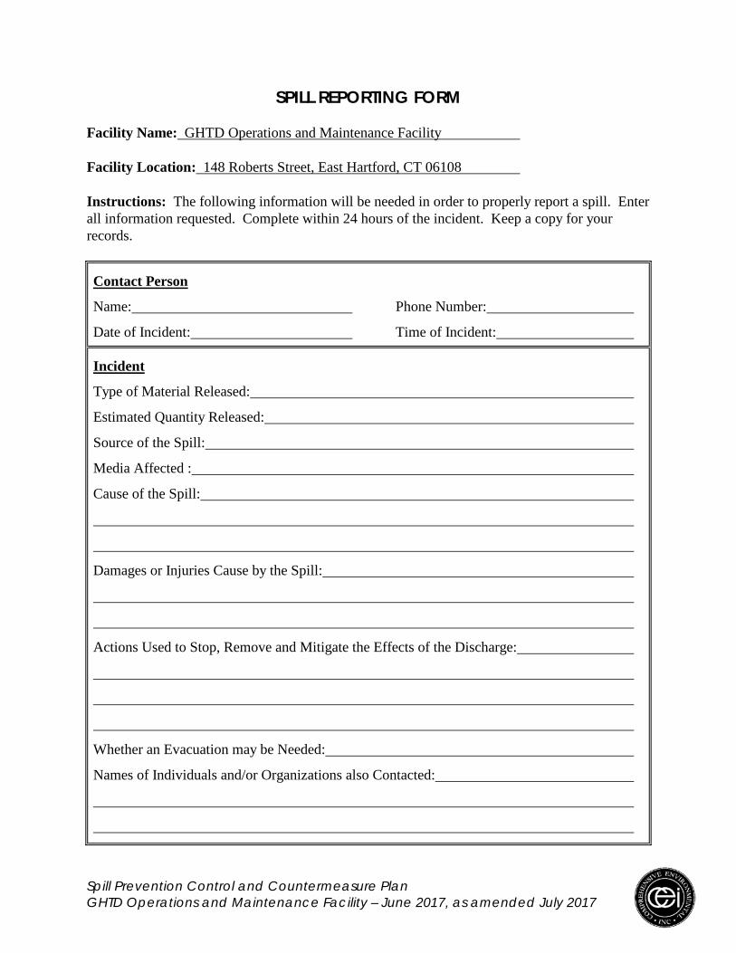
Spill Prevention Control and Countermeasure Plan GHTD Operations and Maintenance Facility – June 2017, as amended July 2017
SPILL REPORTING FORM Facility Name: GHTD Operations and Maintenance Facility Facility Location: 148 Roberts Street, East Hartford, CT 06108 Instructions: The following information will be needed in order to properly report a spill. Enter all information requested. Complete within 24 hours of the incident. Keep a copy for your records.
Contact Person
Name: Phone Number:
Date of Incident: Time of Incident:
Incident
Type of Material Released:
Estimated Quantity Released:
Source of the Spill:
Media Affected :
Cause of the Spill:
Damages or Injuries Cause by the Spill:
Actions Used to Stop, Remove and Mitigate the Effects of the Discharge:
Whether an Evacuation may be Needed:
Names of Individuals and/or Organizations also Contacted:

Page 1 of 4
Pit Stops Fact Sheet
Spill Prevention, Control, and Countermeasure Plans
Legal Requirements
The federal Clean Water Act requires facilities that store any kind of oil above certain volumes
to prepare and implement Spill Prevention, Control and Countermeasure (SPCC) Plans to
prevent the discharge of oil from a facility into navigable waters or adjoining shorelines. “Oil” is
defined in Section 311(a)(1) of the Clean Water Act as “oil of any kind or in any form including,
but not limited to, petroleum, fuel oil, sludge, oil refuse, and oil mixed with wastes other than
dredged spoil.” U.S. Environmental Protection Agency (EPA) interprets this definition to
include crude oil, petroleum and petroleum-refined products, as well as non-petroleum oils such
as vegetable and animal oils, synthetic oils and mineral oils.
SPCC regulations require some facilities to prepare a plan and have adequate containment, such
as berms and dikes around aboveground fuel tanks (ASTs) or use certain double-wall ASTs to
protect the soil and water in the event of a spill [40 CFR 112.1]. Secondary containment is also
required at all loading/unloading areas. SPCC regulations are federal requirements, administered
by EPA.
Legal References Oil definition - 311(a)(1) of the Clean Water Act
Oil pollution prevention - 40 CFR 112.1
Does Your Facility Require a SPCC Plan? Your facility needs to develop an SPCC plan if:
For above ground tanks – it has the capacity to store over 1,320 gallons of oil. This is
counted using the aggregate volume of all tanks 55 gallons or larger. Containers smaller
than 55 gallons are exempt.
For below ground tanks – it has the capacity to store oil in any size tank with an
aggregate volume of 42,000 gallons. (USTs regulated under the CT UST program are
exempt); AND,
There is a reasonable expectation that a discharge of oil to a “navigable water of the
United States” or “adjoining shorelines” would result considering a possible worst-case
scenario. When assessing this risk, manmade features such as secondary containment,
roads, railroads, etc. cannot be used to say “no risk.” The SPCC regulations apply to just
about every facility in the state, since a facility cannot take into consideration any man-
made impediments.
SPCC Plans

Page 2 of 4
NOTE: A facility storing over the threshold quantity of oil and arguing that they are not
a threat to navigable waters should keep a letter explaining why an SPCC Plan is not
necessary for that facility.
What is an SPCC Plan? An SPCC Plan outlines a facility’s oil containment systems and procedures to
prevent an oil spill. It also outlines oil spill response and clean up protocols. Even if
you are not required to have a formal SPCC Plan, you should still consider
implementing the common sense practices that are part of a spill plan.
Each SPCC Plan is site specific, but must address the following:
Operating procedures that prevent oil spills;
Control measures installed to prevent a spill from reaching the environment; and
Countermeasures to contain, clean up, and mitigate the effects of an oil spill that
reaches the environment.
Who Writes an SPCC Plan? SPCC plans are written and certified according to the amount of oil storage capacity on
site. Plans are written for facilities with greater than 10,000 gallons oil storage capacity
or those meeting the criteria below. Plans for facilities with more than 10,000 gallons
on-site oil storage capacity are Tier II and must be certified by a Registered Professional
Engineer.
Written Plans that may be self-certified: Owner/operators of facilities that have
10,000 gallons or less of oil storage capacity may self-certify their plan, if the facility
meets criteria 1 and 2 below. If the facility meets all 3 of the criteria below they are Tier
I and may use the Tier 1 SPCC Template Plan.
1) If facility has a total aboveground oil storage capacity of 10,000 U.S. gallons or
less;
2) If in the 3 years prior to the date the SPCC Plan is certified, facility had no single
discharge of oil to navigable waters or adjoining shorelines exceeding 1,000 U.S.
gallons, or no two discharges of oil to navigable waters or adjoining shorelines each
exceeding 42 U.S. gallons within any 12-month period; and,
3) Facility has no aboveground oil storage containers with a capacity greater than
5,000 U.S. gallons.
Is There a Particular Form or Format for the full SPCC Plan? EPA does not expect any two plans to look alike. However, at a minimum, all plans
must include:
Facility diagram and description;
Facility drainage;
List of all oil storage tanks and areas;

Page 3 of 4
Quantities of oil that could be released, with predicted path of flow and flow rate; oil
discharge predictions;
Procedures for receiving oil from supplier, transfer of oil within the facility, end point
uses of the oil, waste oil disposal; transfer procedures and equipment including piping;
Capacity of required secondary containment; appropriate secondary containment or
diversionary structures;
Clean-up procedures, use of in-house staff versus contractors;
Notification list. Name(s) and phone numbers of in-house management, remote
management, fire and police, municipal, state and federal agencies requiring notification;
Site security for prevention of internal sabotage, external vandalism;
Employee training for spill prevention, oil handling, and spill clean-up; personnel
training and oil discharge prevention briefings;
Facility inspections;
Requirements for bulk storage containers including inspections, overfill, and integrity
testing requirements;
Requirements for qualified oil filled operational equipment;
Loading/unloading rack requirement and procedures for tank car and tank trucks;
Brittle fracture evaluations for aboveground field constructed containers;
Record-keeping requirements;
Five year plan review;
Management approval; and
Plan certification (by professional engineer or in certain cases by facility owner/operator).
A sample SPCC Plan which can be used for a Tier 2 Plan is available in Appendix D of the
“SPCC Guidance for Regional Inspectors” on the EPA website. A sample Tier I SPCC Plan is
also available on the EPA website.
Where Should the SPCC Plan be Located? Facilities staffed at least 4 hours per day are required to keep the plan onsite. Facilities staffed
less than 4 hours per day can keep the plan at the nearest field office. A copy does not have to be
filed with EPA. However, the SPCC plan must be available during normal business hours for
review by an EPA inspector.
All employees that handle or manage oil must be made aware of the SPCC Plan.
It is highly recommended that copies of the Plan and best management practices be posted in
plain view or accessible on file at oil storage locations.
Does an SPCC Plan Need to be Reviewed and/or Updated? The owner/operators must review the Plan at least once every five years and keep records
of these reviews. An example of such documentation is “I have completed review and
evaluation of the SPCC plan for (name of facility) on (date), and will/will not amend the
plan as a result (signature).”

Page 4 of 4
The plan must be amended when there are changes in facility design,
construction, operation or maintenance which materially affect the facility’s
potential for the discharge of oil; or if there are two or more spills in 12 months,
or one spill of at least 1,000 gallons.
Only technical changes to the SPCC plan must be certified by a Registered
Professional Engineer. Non-technical amendments include personnel or contact
information changes.
Who Cares if My Facility Has a Plan?
Company management. Having measures in place to prevent spills is cost
effective, since spill cleanup can be costly. When a plan is in place, spill cleanup
can be more efficient, more effective, and less costly than if there is no course of
action.
The U.S. EPA. The penalty for failure to have an SPCC Plan can be up to
$32,500 per day for violations occurring from March 16, 2004 through January
12, 2009 and up to $37,500 per day for violations occurring after January 12,
2011 up to a maximum of $137,500, if an administrative action is filed. The EPA
performs random, unannounced inspections of facilities every year.
What Could You Be Held Responsible for if there is a Spill? Removing the material from public property. Cleaning of highways, waterways,
storm drains, bridge abutments, etc.
Removing the material from private property, such as boat hulls and parking lots.
Paying for natural resources damages (lost parking receipts at public beaches; lost
revenues from fishing licenses; replacing killed fish, shellfish, and waterfowl).
Paying for lost livelihood wages of fishermen and shell fisherman, devaluation of
property for sale. Private suits.
Civil penalty for spilling into a water of the U.S.
Possibility that if you fail to notify the federal authorities of a spill it could lead to
a criminal penalty. Responsibility for spill notification is the owner/operators.
For questions about the federal SPCC program, visit EPA’s SPCC webpage or call
Cosmo Caterino, EPA-Region 1 at 617-918-1264.
Did You Know? Moral of the story: It’s a lot cheaper to prevent a release than to clean
one up.
2014 Pit Stops Fact Sheets. Connecticut Department of Energy and Environmental Protection,
Office of Pollution Prevention, 860-424-3297. Updated April 2014 www.ct.gov/deep/pitstops
Spill Prevention Control and Countermeasure Plan GHTD Operations and Maintenance Facility – June 2017, as amended July 2017
Appendix H – Certifications
• Facility Certification • Registered Professional Engineer
Certification • Owner Review • Certification of Substantial Harm
Determination

FACITITY CERTIFICATION
Facility InformationName:Address:Description:
Owner InformationName:Address:Phone:
GHTD Ooerations and ce Facil itv148 Ro Sfreef F.ast Hartforul CT O6l 08
Greater Hartford Transit District1 Ii Place- Hartforul cT 061 03R60J4 -5125
Operator InformationName: Fìrst Inc-Address:Phone:
600 vine Street- 1400. c oH 4s ?02866- 83
SPCC Plan Coordinator(s)Name:Title:
Lontz.
Spill History InformationProvided in sPCC Plan in section 4.0, previous Spill Evenrs (rlz.7(a))
Management ApprovalI have read the SPCC Plan and hereby authorize full approval of the plan and commit thenecessary resources to achieve full
Signature:
Name:
Title:
Date:
Spi/l Prevenfion Confrol ond Countermeosure p/onGHTD Operotions ond Moinfenonce Focilily - June 2017, as omended Juty 20I7
t


I
OWNER REVIEW
coraplete the following furrn at least once ev,eryììi.f..3r:. certifying thar you either wilr or wi,not amend the SpCC plan as required unóer 4OCFR I 12.5.
Faeility lnformationName;Address;Desøiption:
Owner InformafionName:
Address:Phone:
[-lnion P 06¡ 37 -5325
Operator lnformationNarne;AddressPhone: 383
Owner or Operator Review ¿nd Evaluation Ctr have completed revrew and
JÞe#{Ð Operations and
',\q1llTllc-ircle) amend the plan
ertilicafionof the SPCC plan furMaíntenance Facility on date) and wÍttas a result"
Sþature:
Name:
Titie:
Date:
Spill Prevenfion Canfra! and Caunlermeasure plenGHTD Õperaríons and Mointenon"à rãàitfty - June 2t r 7. as omended Juty zQ I Z @

CERTIFICATION OF SUBSTANTIAT HARM DETERMINATION
Facility Name: GHTD operations and Maintenance FacirityFacilify Address: 148 Roberts Streer, East Hartford CT 06iOS
l ' Does the facility transfer oil over water to or from vessels and does the facility have a total oilstorage capacity greafer than or equal to 42,000 gallons?Yes_ No ¿
l' Does the facility have a totaloil storage capacity greater than or equal to I million gallons anddoes the facility lack secondary containment that is suffìciently large to contain the capacity of thelargest aboveground oil storage tank plus sufficient freeboard io attow for precipitation within anyaboveground oil storage tank area?Yes _ No x*
3' Does the facility have a total oil storage capacity greater than or equal to I million gallons and isthe facility located at a distance (as calculated using the appropriate formula in Attachment C-III tothis appendix or a comparable formular ) such tttutã ¿lr.ná.g" fro* the facility could cause injury tofish and wildlife and sensitive environments? For further deõription of fish and wildlife andsensitive environments, see Appendices [, II, and III to Doc/NôAA', ..Cuidance for Facility andVessel Response Plans: Fish and Wildlife and Sensitive Environments" (see Appendix E to this pan,section 13, for availability) and the applicable Area contingency plan.Yes No x
{ ltoes the facility have a total oil storage capacity greater than or equal to I million gallons and isthe facility located at a distance (as calculatedusing lhe appropriate formula in Atrachment C-III tothis appendix or a comparable formular ) such tnat a ¿isctra.g. fro* the facility would shut down apublic drinking water intaker ?I lf a comparable fomula ts used. documentation of'the reliabiliry and analyrrcal soundness of the comparable formula must be attached to this form.2 For the purposes of40 CFR pan I l2' public drinking *ater intat es are analogous ro public water systems as described at:10 cFR 143.2(c).Yes _ No x*
5' Does the facility have a total oil storage capacity greater than or equal to 1 million gallons andhas the facility experienced a reportable oil diicharg" in un amounr greater than or equal to 10,000gallons within the last 5 vears?Yes_ No r
Certification:I ce*ifu under penalty of law that I have personally examined and am familiar with the informationsubmitted in th that based on my inquiry of those individuals responsible foro that the submitted information is true, accurate, and complete
ODate
Name or print)
Spill Prevention Controt ond Couniermeosure p/onGHTD operotions ond Moinfenonce Foctltfy - June 2017, osomended July 2017

Spill Prevention Control and Countermeasure Plan GHTD Operations and Maintenance Facility – June 2017, as amended July 2017
Appendix I – Record of Changes / Plan Amendments

Spill Prevention Control and Countermeasure Plan GHTD Operations and Maintenance Facility – June 2017, as amended July 2017
RECORD OF CHANGES / PLAN AMENDMENTS The SPCC Plan shall be updated whenever there is a change in the “facility design, construction, operation or maintenance that materially affects its potential for a discharge as described in 40 CFR 112.1(b).” These plan amendments must be prepared within six months and implemented as soon as possible, but no later than six months following preparation of the amendment. In addition, a complete review and evaluation of the SPCC plan shall be completed at least once every five years. All technical amendments to the SPCC Plan shall be certified by a registered Professional Engineer (see certification). All amendments to the plan shall be recorded on this sheet and maintained with the plan.
Revision Number
Revision Date Description of Revisions Certified By
1
June, 2017 New SPCC Plan Nick Cristofori, P.E. Comprehensive Environmental, Inc.
2
3
4
5
6
Amendments shall be recorded in each copy of the SPCC Plans, as listed below: Location of SPCC Plan
Quantity of Plans
GHTD Operations and Maintenance Facility 1 GHTD Headquarters 1