SPG8000 Master Sync / Clock Reference Generator - Tektronix
139
SPG8000 Master Sync / Clock Reference Generator ZZZ Service Manual xx www.tek.com *P077074902* 077-0749-02
-
Upload
khangminh22 -
Category
Documents
-
view
1 -
download
0
Transcript of SPG8000 Master Sync / Clock Reference Generator - Tektronix

SPG8000Master Sync / Clock Reference Generator
ZZZ
Service Manual
xx
www.tek.com
*P077074902*
077-0749-02

Copyright © Tektronix. All rights reserved. Licensed software products are owned by Tektronix or its subsidiariesor suppliers, and are protected by national copyright laws and international treaty provisions.
Tektronix products are covered by U.S. and foreign patents, issued and pending. Information in this publicationsupersedes that in all previously published material. Specifications and price change privileges reserved.
TEKTRONIX and TEK are registered trademarks of Tektronix, Inc.
Contacting Tektronix
Tektronix, Inc.14150 SW Karl Braun DriveP.O. Box 500Beaverton, OR 97077USA
For product information, sales, service, and technical support:In North America, call 1-800-833-9200.Worldwide, visit www.tek.com to find contacts in your area.

Warranty
Tektronix warrants that this product will be free from defects in materials and workmanship for a period of one (1)year from the date of shipment. If any such product proves defective during this warranty period, Tektronix, at itsoption, either will repair the defective product without charge for parts and labor, or will provide a replacementin exchange for the defective product. Parts, modules and replacement products used by Tektronix for warrantywork may be new or reconditioned to like new performance. All replaced parts, modules and products becomethe property of Tektronix.
In order to obtain service under this warranty, Customer must notify Tektronix of the defect before the expiration ofthe warranty period and make suitable arrangements for the performance of service. Customer shall be responsiblefor packaging and shipping the defective product to the service center designated by Tektronix, with shippingcharges prepaid. Tektronix shall pay for the return of the product to Customer if the shipment is to a location withinthe country in which the Tektronix service center is located. Customer shall be responsible for paying all shippingcharges, duties, taxes, and any other charges for products returned to any other locations.
This warranty shall not apply to any defect, failure or damage caused by improper use or improper or inadequatemaintenance and care. Tektronix shall not be obligated to furnish service under this warranty a) to repair damageresulting from attempts by personnel other than Tektronix representatives to install, repair or service the product;b) to repair damage resulting from improper use or connection to incompatible equipment; c) to repair any damageor malfunction caused by the use of non-Tektronix supplies; or d) to service a product that has been modified orintegrated with other products when the effect of such modification or integration increases the time or difficultyof servicing the product.
THIS WARRANTY IS GIVEN BY TEKTRONIX WITH RESPECT TO THE PRODUCT IN LIEU OF ANYOTHER WARRANTIES, EXPRESS OR IMPLIED. TEKTRONIX AND ITS VENDORS DISCLAIM ANYIMPLIED WARRANTIES OF MERCHANTABILITY OR FITNESS FOR A PARTICULAR PURPOSE.TEKTRONIX' RESPONSIBILITY TO REPAIR OR REPLACE DEFECTIVE PRODUCTS IS THE SOLEAND EXCLUSIVE REMEDY PROVIDED TO THE CUSTOMER FOR BREACH OF THIS WARRANTY.TEKTRONIX AND ITS VENDORS WILL NOT BE LIABLE FOR ANY INDIRECT, SPECIAL, INCIDENTAL,OR CONSEQUENTIAL DAMAGES IRRESPECTIVE OF WHETHER TEKTRONIX OR THE VENDOR HASADVANCE NOTICE OF THE POSSIBILITY OF SUCH DAMAGES.
[W2 – 15AUG04]


Table of Contents
Important safety information . . . . . . . . . . . . . . . . . . . . . . . . . . . . . . . . . . . . . . . . . . . . . . . . . . . . . . . . . . . . . . . . . . . . . . . . . . . . . . . . . . . . . iv
General safety summary . . . . . . . . . . . . . . . . . . . . . . . . . . . . . . . . . . . . . . . . . . . . . . . . . . . . . . . . . . . . . . . . . . . . . . . . . . . . . . . . . . . . . iv
Service safety summary .. . . . . . . . . . . . . . . . . . . . . . . . . . . . . . . . . . . . . . . . . . . . . . . . . . . . . . . . . . . . . . . . . . . . . . . . . . . . . . . . . . . . . vi
Terms in this manual . . . . . . . . . . . . . . . . . . . . . . . . . . . . . . . . . . . . . . . . . . . . . . . . . . . . . . . . . . . . . . . . . . . . . . . . . . . . . . . . . . . . . . . . vii
Symbols and terms on the product . . . . . . . . . . . . . . . . . . . . . . . . . . . . . . . . . . . . . . . . . . . . . . . . . . . . . . . . . . . . . . . . . . . . . . . . . vii
Preface .. . . . . . . . . . . . . . . . . . . . . . . . . . . . . . . . . . . . . . . . . . . . . . . . . . . . . . . . . . . . . . . . . . . . . . . . . . . . . . . . . . . . . . . . . . . . . . . . . . . . . . . . . . . . . ix
Manual structure . . . . . . . . . . . . . . . . . . . . . . . . . . . . . . . . . . . . . . . . . . . . . . . . . . . . . . . . . . . . . . . . . . . . . . . . . . . . . . . . . . . . . . . . . . . . . . ix
Manual conventions . . . . . . . . . . . . . . . . . . . . . . . . . . . . . . . . . . . . . . . . . . . . . . . . . . . . . . . . . . . . . . . . . . . . . . . . . . . . . . . . . . . . . . . . . . . x
Product documentation. . . . . . . . . . . . . . . . . . . . . . . . . . . . . . . . . . . . . . . . . . . . . . . . . . . . . . . . . . . . . . . . . . . . . . . . . . . . . . . . . . . . . . . xi
Theory of operation . . . . . . . . . . . . . . . . . . . . . . . . . . . . . . . . . . . . . . . . . . . . . . . . . . . . . . . . . . . . . . . . . . . . . . . . . . . . . . . . . . . . . . . . . . . . . . . . 1
Base instrument theory of operation .. . . . . . . . . . . . . . . . . . . . . . . . . . . . . . . . . . . . . . . . . . . . . . . . . . . . . . . . . . . . . . . . . . . . . . . . 1
Optional modules theory of operation .. . . . . . . . . . . . . . . . . . . . . . . . . . . . . . . . . . . . . . . . . . . . . . . . . . . . . . . . . . . . . . . . . . . . . . 4
Adjustment procedures. . . . . . . . . . . . . . . . . . . . . . . . . . . . . . . . . . . . . . . . . . . . . . . . . . . . . . . . . . . . . . . . . . . . . . . . . . . . . . . . . . . . . . . . . . . . 13
Adjust master clock using a frequency signal generator . . . . . . . . . . . . . . . . . . . . . . . . . . . . . . . . . . . . . . . . . . . . . . . . . 13
Adjust master clock while locked to GPS.. . . . . . . . . . . . . . . . . . . . . . . . . . . . . . . . . . . . . . . . . . . . . . . . . . . . . . . . . . . . . . . . . 16
Adjust Option BG... . . . . . . . . . . . . . . . . . . . . . . . . . . . . . . . . . . . . . . . . . . . . . . . . . . . . . . . . . . . . . . . . . . . . . . . . . . . . . . . . . . . . . . . . . . 18
Adjust Genlock/Black board .. . . . . . . . . . . . . . . . . . . . . . . . . . . . . . . . . . . . . . . . . . . . . . . . . . . . . . . . . . . . . . . . . . . . . . . . . . . . . . . 24
Adjust Option SDI .. . . . . . . . . . . . . . . . . . . . . . . . . . . . . . . . . . . . . . . . . . . . . . . . . . . . . . . . . . . . . . . . . . . . . . . . . . . . . . . . . . . . . . . . . . . 26
Maintenance.. . . . . . . . . . . . . . . . . . . . . . . . . . . . . . . . . . . . . . . . . . . . . . . . . . . . . . . . . . . . . . . . . . . . . . . . . . . . . . . . . . . . . . . . . . . . . . . . . . . . . . . 33
General service information . . . . . . . . . . . . . . . . . . . . . . . . . . . . . . . . . . . . . . . . . . . . . . . . . . . . . . . . . . . . . . . . . . . . . . . . . . . . . . . . . 33
Inspection and cleaning .. . . . . . . . . . . . . . . . . . . . . . . . . . . . . . . . . . . . . . . . . . . . . . . . . . . . . . . . . . . . . . . . . . . . . . . . . . . . . . . . . . . . . 36
Remove and replace procedures . . . . . . . . . . . . . . . . . . . . . . . . . . . . . . . . . . . . . . . . . . . . . . . . . . . . . . . . . . . . . . . . . . . . . . . . . . . . 39
Troubleshooting. . . . . . . . . . . . . . . . . . . . . . . . . . . . . . . . . . . . . . . . . . . . . . . . . . . . . . . . . . . . . . . . . . . . . . . . . . . . . . . . . . . . . . . . . . . . . . . 67
Repackaging instructions . . . . . . . . . . . . . . . . . . . . . . . . . . . . . . . . . . . . . . . . . . . . . . . . . . . . . . . . . . . . . . . . . . . . . . . . . . . . . . . . . . 107
Replaceable parts . . . . . . . . . . . . . . . . . . . . . . . . . . . . . . . . . . . . . . . . . . . . . . . . . . . . . . . . . . . . . . . . . . . . . . . . . . . . . . . . . . . . . . . . . . . . . . . . 109
Parts ordering information . . . . . . . . . . . . . . . . . . . . . . . . . . . . . . . . . . . . . . . . . . . . . . . . . . . . . . . . . . . . . . . . . . . . . . . . . . . . . . . . . 109
Replaceable parts lists . . . . . . . . . . . . . . . . . . . . . . . . . . . . . . . . . . . . . . . . . . . . . . . . . . . . . . . . . . . . . . . . . . . . . . . . . . . . . . . . . . . . . . 111
SPG8000 Master Sync / Clock Reference Generator Service Manual i

Table of Contents
List of Figures
Figure 1: SPG8000 block diagram .. . . . . . . . . . . . . . . . . . . . . . . . . . . . . . . . . . . . . . . . . . . . . . . . . . . . . . . . . . . . . . . . . . . . . . . . . . . . . . 2
Figure 2: Simplified block diagram of the Option AG ... . . . . . . . . . . . . . . . . . . . . . . . . . . . . . . . . . . . . . . . . . . . . . . . . . . . . . 4
Figure 3: Simplified block diagram of the Option BG ... . . . . . . . . . . . . . . . . . . . . . . . . . . . . . . . . . . . . . . . . . . . . . . . . . . . . . 5
Figure 4: Simplified block diagram of the Genlock/Black and Option GPS circuitry . . . . . . . . . . . . . . . . . . . . . . 7
Figure 5: Simplified block diagram of Option SDI . . . . . . . . . . . . . . . . . . . . . . . . . . . . . . . . . . . . . . . . . . . . . . . . . . . . . . . . . . . 10
Figure 6: Adjusting the master clock frequency using a frequency standard . . . . . . . . . . . . . . . . . . . . . . . . . . . . . . . 14
Figure 7: Variable resistors on the Option BG board .. . . . . . . . . . . . . . . . . . . . . . . . . . . . . . . . . . . . . . . . . . . . . . . . . . . . . . . . . 19
Figure 8: Adjusting the Option BG output offset and gain . . . . . . . . . . . . . . . . . . . . . . . . . . . . . . . . . . . . . . . . . . . . . . . . . . . 19
Figure 9: Adjusting chroma gain .. . . . . . . . . . . . . . . . . . . . . . . . . . . . . . . . . . . . . . . . . . . . . . . . . . . . . . . . . . . . . . . . . . . . . . . . . . . . . . . 22
Figure 10: Triggered display for adjusting the Option BG chroma gain .. . . . . . . . . . . . . . . . . . . . . . . . . . . . . . . . . . . 23
Figure 11: Equipment connections for Genlock/Black adjustments . . . . . . . . . . . . . . . . . . . . . . . . . . . . . . . . . . . . . . . . . 24
Figure 12: Instrument orientation.. . . . . . . . . . . . . . . . . . . . . . . . . . . . . . . . . . . . . . . . . . . . . . . . . . . . . . . . . . . . . . . . . . . . . . . . . . . . . . . 40
Figure 13: Module locator diagram .. . . . . . . . . . . . . . . . . . . . . . . . . . . . . . . . . . . . . . . . . . . . . . . . . . . . . . . . . . . . . . . . . . . . . . . . . . . . 41
Figure 14: Cable connections 1 of 3. . . . . . . . . . . . . . . . . . . . . . . . . . . . . . . . . . . . . . . . . . . . . . . . . . . . . . . . . . . . . . . . . . . . . . . . . . . . . 42
Figure 15: Cable connections 2 of 3. . . . . . . . . . . . . . . . . . . . . . . . . . . . . . . . . . . . . . . . . . . . . . . . . . . . . . . . . . . . . . . . . . . . . . . . . . . . . 43
Figure 16: Cable connections 3 of 3. . . . . . . . . . . . . . . . . . . . . . . . . . . . . . . . . . . . . . . . . . . . . . . . . . . . . . . . . . . . . . . . . . . . . . . . . . . . . 44
Figure 17: Removing the top cover . . . . . . . . . . . . . . . . . . . . . . . . . . . . . . . . . . . . . . . . . . . . . . . . . . . . . . . . . . . . . . . . . . . . . . . . . . . . . 46
Figure 18: Removing the front panel assembly .. . . . . . . . . . . . . . . . . . . . . . . . . . . . . . . . . . . . . . . . . . . . . . . . . . . . . . . . . . . . . . . 49
Figure 19: Disassembling the front panel assembly . . . . . . . . . . . . . . . . . . . . . . . . . . . . . . . . . . . . . . . . . . . . . . . . . . . . . . . . . . . 50
Figure 20: Removing the power supply. . . . . . . . . . . . . . . . . . . . . . . . . . . . . . . . . . . . . . . . . . . . . . . . . . . . . . . . . . . . . . . . . . . . . . . . . 53
Figure 21: Removing the Power Combiner board . . . . . . . . . . . . . . . . . . . . . . . . . . . . . . . . . . . . . . . . . . . . . . . . . . . . . . . . . . . . . 54
Figure 22: Remove the two nuts . . . . . . . . . . . . . . . . . . . . . . . . . . . . . . . . . . . . . . . . . . . . . . . . . . . . . . . . . . . . . . . . . . . . . . . . . . . . . . . . . 62
Figure 23: Remove the bracket from the fan . . . . . . . . . . . . . . . . . . . . . . . . . . . . . . . . . . . . . . . . . . . . . . . . . . . . . . . . . . . . . . . . . . . 63
Figure 24: Main board (view from top) . . . . . . . . . . . . . . . . . . . . . . . . . . . . . . . . . . . . . . . . . . . . . . . . . . . . . . . . . . . . . . . . . . . . . . . . . 74
Figure 25: Option AG troubleshooting procedure . . . . . . . . . . . . . . . . . . . . . . . . . . . . . . . . . . . . . . . . . . . . . . . . . . . . . . . . . . . . . 76
Figure 26: Option BG troubleshooting procedure . . . . . . . . . . . . . . . . . . . . . . . . . . . . . . . . . . . . . . . . . . . . . . . . . . . . . . . . . . . . . 78
Figure 27: Genlock/Black generator module power supply test . . . . . . . . . . . . . . . . . . . . . . . . . . . . . . . . . . . . . . . . . . . . . 83
Figure 28: Genlock/Black generator board voltage test point and fuse locations . . . . . . . . . . . . . . . . . . . . . . . . . . 85
Figure 29: SDI power supply test points. . . . . . . . . . . . . . . . . . . . . . . . . . . . . . . . . . . . . . . . . . . . . . . . . . . . . . . . . . . . . . . . . . . . . . 104
Figure 30: Main instrument exploded view .. . . . . . . . . . . . . . . . . . . . . . . . . . . . . . . . . . . . . . . . . . . . . . . . . . . . . . . . . . . . . . . . . 111
Figure 31: Chassis assembly exploded view .. . . . . . . . . . . . . . . . . . . . . . . . . . . . . . . . . . . . . . . . . . . . . . . . . . . . . . . . . . . . . . . . 113
Figure 32: Front panel assembly exploded view.. . . . . . . . . . . . . . . . . . . . . . . . . . . . . . . . . . . . . . . . . . . . . . . . . . . . . . . . . . . . 115
Figure 33: Option AG exploded view.. . . . . . . . . . . . . . . . . . . . . . . . . . . . . . . . . . . . . . . . . . . . . . . . . . . . . . . . . . . . . . . . . . . . . . . . 116
Figure 34: Option BG exploded view .. . . . . . . . . . . . . . . . . . . . . . . . . . . . . . . . . . . . . . . . . . . . . . . . . . . . . . . . . . . . . . . . . . . . . . . . 117
Figure 35: Genlock/Black generator board and Option GPS Receiver board exploded view .. . . . . . . . . 119
Figure 36: Option SDI board and Option SDI Output board exploded view .. . . . . . . . . . . . . . . . . . . . . . . . . . . . 121
ii SPG8000 Master Sync / Clock Reference Generator Service Manual

Table of Contents
List of Tables
Table i: Product documentation.. . . . . . . . . . . . . . . . . . . . . . . . . . . . . . . . . . . . . . . . . . . . . . . . . . . . . . . . . . . . . . . . . . . . . . . . . . . . . . . . . xiTable 1: Equipment required to adjust the master clock using a signal generator. . . . . . . . . . . . . . . . . . . . . . . . . . 14Table 2: Equipment required to adjust the master clock while locked to GPS .. . . . . . . . . . . . . . . . . . . . . . . . . . . . 16Table 3: Adjusting Option BG ... . . . . . . . . . . . . . . . . . . . . . . . . . . . . . . . . . . . . . . . . . . . . . . . . . . . . . . . . . . . . . . . . . . . . . . . . . . . . . . . . 18Table 4: Equipment required for the Genlock/Black board adjustment procedures. . . . . . . . . . . . . . . . . . . . . . . . 24Table 5: Equipment required for the Option SDI adjustment procedures . . . . . . . . . . . . . . . . . . . . . . . . . . . . . . . . . . . 26Table 6: SDI output amplitude . . . . . . . . . . . . . . . . . . . . . . . . . . . . . . . . . . . . . . . . . . . . . . . . . . . . . . . . . . . . . . . . . . . . . . . . . . . . . . . . . . . 27Table 7: External inspection checklist. . . . . . . . . . . . . . . . . . . . . . . . . . . . . . . . . . . . . . . . . . . . . . . . . . . . . . . . . . . . . . . . . . . . . . . . . . . 37Table 8: Internal inspection checklist . . . . . . . . . . . . . . . . . . . . . . . . . . . . . . . . . . . . . . . . . . . . . . . . . . . . . . . . . . . . . . . . . . . . . . . . . . . 37Table 9: Required tools for removal and replacement of modules . . . . . . . . . . . . . . . . . . . . . . . . . . . . . . . . . . . . . . . . . . . 40Table 10: Cable connections table 1 of 3 . . . . . . . . . . . . . . . . . . . . . . . . . . . . . . . . . . . . . . . . . . . . . . . . . . . . . . . . . . . . . . . . . . . . . . . 42Table 11: Cable connections table 2 of 3 . . . . . . . . . . . . . . . . . . . . . . . . . . . . . . . . . . . . . . . . . . . . . . . . . . . . . . . . . . . . . . . . . . . . . . . 43Table 12: Cable connections table 3 of 3 . . . . . . . . . . . . . . . . . . . . . . . . . . . . . . . . . . . . . . . . . . . . . . . . . . . . . . . . . . . . . . . . . . . . . . . 44Table 13: Slot I/O test error codes . . . . . . . . . . . . . . . . . . . . . . . . . . . . . . . . . . . . . . . . . . . . . . . . . . . . . . . . . . . . . . . . . . . . . . . . . . . . . . . 70Table 14: SPG8000 system diagnostics . . . . . . . . . . . . . . . . . . . . . . . . . . . . . . . . . . . . . . . . . . . . . . . . . . . . . . . . . . . . . . . . . . . . . . . . . 71Table 15: SPG8000 troubleshooting procedures . . . . . . . . . . . . . . . . . . . . . . . . . . . . . . . . . . . . . . . . . . . . . . . . . . . . . . . . . . . . . . . 73Table 16: Equipment required to troubleshoot the Option AG ... . . . . . . . . . . . . . . . . . . . . . . . . . . . . . . . . . . . . . . . . . . . . 75Table 17: Equipment required for Option BG troubleshooting. . . . . . . . . . . . . . . . . . . . . . . . . . . . . . . . . . . . . . . . . . . . . . . 77Table 18: Equipment required for troubleshooting the Genlock/Black generator module . . . . . . . . . . . . . . . . 79Table 19: General problems – Genlock/Black board .. . . . . . . . . . . . . . . . . . . . . . . . . . . . . . . . . . . . . . . . . . . . . . . . . . . . . . . . . 80Table 20: POST error codes for the Genlock/Black module. . . . . . . . . . . . . . . . . . . . . . . . . . . . . . . . . . . . . . . . . . . . . . . . . . 81Table 21: Power supply test points . . . . . . . . . . . . . . . . . . . . . . . . . . . . . . . . . . . . . . . . . . . . . . . . . . . . . . . . . . . . . . . . . . . . . . . . . . . . . . 84Table 22: Equipment required for troubleshooting the Option GPS module . . . . . . . . . . . . . . . . . . . . . . . . . . . . . . . 89Table 23: General problems – Option GPS.. . . . . . . . . . . . . . . . . . . . . . . . . . . . . . . . . . . . . . . . . . . . . . . . . . . . . . . . . . . . . . . . . . . . 90Table 24: POST error code for Option GPS .. . . . . . . . . . . . . . . . . . . . . . . . . . . . . . . . . . . . . . . . . . . . . . . . . . . . . . . . . . . . . . . . . . . 91Table 25: Equipment required to troubleshoot the Option SDI .. . . . . . . . . . . . . . . . . . . . . . . . . . . . . . . . . . . . . . . . . . . . . 95Table 26: Option SDI troubleshooting .. . . . . . . . . . . . . . . . . . . . . . . . . . . . . . . . . . . . . . . . . . . . . . . . . . . . . . . . . . . . . . . . . . . . . . . . . 96Table 27: POST error codes for Option SDI . . . . . . . . . . . . . . . . . . . . . . . . . . . . . . . . . . . . . . . . . . . . . . . . . . . . . . . . . . . . . . . . . . . 97Table 28: Option SDI module factory default settings . . . . . . . . . . . . . . . . . . . . . . . . . . . . . . . . . . . . . . . . . . . . . . . . . . . . . . 100Table 29: Parts list column descriptions . . . . . . . . . . . . . . . . . . . . . . . . . . . . . . . . . . . . . . . . . . . . . . . . . . . . . . . . . . . . . . . . . . . . . . 110Table 30: Main instrument replaceable parts . . . . . . . . . . . . . . . . . . . . . . . . . . . . . . . . . . . . . . . . . . . . . . . . . . . . . . . . . . . . . . . . . 111Table 31: Chassis assembly replaceable parts . . . . . . . . . . . . . . . . . . . . . . . . . . . . . . . . . . . . . . . . . . . . . . . . . . . . . . . . . . . . . . . . 112Table 32: Front panel assembly replaceable parts . . . . . . . . . . . . . . . . . . . . . . . . . . . . . . . . . . . . . . . . . . . . . . . . . . . . . . . . . . . 114Table 33: Option AG – replaceable parts . . . . . . . . . . . . . . . . . . . . . . . . . . . . . . . . . . . . . . . . . . . . . . . . . . . . . . . . . . . . . . . . . . . . . 116Table 34: Option BG – replaceable parts . . . . . . . . . . . . . . . . . . . . . . . . . . . . . . . . . . . . . . . . . . . . . . . . . . . . . . . . . . . . . . . . . . . . . 117Table 35: Genlock/Black board and Option GPS Receiver board – replaceable parts. . . . . . . . . . . . . . . . . . . 118Table 36: Option SDI – replaceable parts. . . . . . . . . . . . . . . . . . . . . . . . . . . . . . . . . . . . . . . . . . . . . . . . . . . . . . . . . . . . . . . . . . . . . 120Table 37: Standard and optional accessories for the SPG8000.. . . . . . . . . . . . . . . . . . . . . . . . . . . . . . . . . . . . . . . . . . . . 122
SPG8000 Master Sync / Clock Reference Generator Service Manual iii

Important safety information
Important safety informationThis manual contains information and warnings that must be followed by the userfor safe operation and to keep the product in a safe condition.
To safely perform service on this product, additional information is provided atthe end of this section. (See page vi, Service safety summary.)
General safety summaryUse the product only as specified. Review the following safety precautions toavoid injury and prevent damage to this product or any products connected to it.Carefully read all instructions. Retain these instructions for future reference.
Comply with local and national safety codes.
For correct and safe operation of the product, it is essential that you followgenerally accepted safety procedures in addition to the safety precautions specifiedin this manual.
The product is designed to be used by trained personnel only.
Only qualified personnel who are aware of the hazards involved should removethe cover for repair, maintenance, or adjustment.
Before use, always check the product with a known source to be sure it isoperating correctly.
This product is not intended for detection of hazardous voltages.
While using this product, you may need to access other parts of a larger system.Read the safety sections of the other component manuals for warnings andcautions related to operating the system.
When incorporating this equipment into a system, the safety of that system is theresponsibility of the assembler of the system.
iv SPG8000 Master Sync / Clock Reference Generator Service Manual

Important safety information
To avoid fire or personalinjury
Use proper power cord. Use only the power cord specified for this product andcertified for the country of use.
Ground the product. This product is grounded through the grounding conductorof the power cord. To avoid electric shock, the grounding conductor must beconnected to earth ground. Before making connections to the input or outputterminals of the product, make sure that the product is properly grounded.
Do not disable the power cord grounding connection.
Power disconnect. The power cord disconnects the product from the powersource. See instructions for the location. Do not position the equipment so thatit is difficult to operate the power cord; it must remain accessible to the user atall times to allow for quick disconnection if needed.
Observe all terminal ratings. To avoid fire or shock hazard, observe all ratingsand markings on the product. Consult the product manual for further ratingsinformation before making connections to the product.
Do not apply a potential to any terminal, including the common terminal, thatexceeds the maximum rating of that terminal.
Do not operate without covers. Do not operate this product with covers or panelsremoved, or with the case open. Hazardous voltage exposure is possible.
Avoid exposed circuitry. Do not touch exposed connections and componentswhen power is present.
Do not operate with suspected failures. If you suspect that there is damage to thisproduct, have it inspected by qualified service personnel.
Disable the product if it is damaged. Do not use the product if it is damagedor operates incorrectly. If in doubt about safety of the product, turn it off anddisconnect the power cord. Clearly mark the product to prevent its furtheroperation.
Before use, inspect voltage probes, test leads, and accessories for mechanicaldamage and replace when damaged. Do not use probes or test leads if they aredamaged, if there is exposed metal, or if a wear indicator shows.
Examine the exterior of the product before you use it. Look for cracks or missingpieces.
Use only specified replacement parts.
Do not operate in wet/damp conditions. Be aware that condensation may occur ifa unit is moved from a cold to a warm environment.
Do not operate in an explosive atmosphere.
Keep product surfaces clean and dry. Remove the input signals before you cleanthe product.
SPG8000 Master Sync / Clock Reference Generator Service Manual v

Important safety information
Provide proper ventilation. Refer to the installation instructions in the manual fordetails on installing the product so it has proper ventilation.
Slots and openings are provided for ventilation and should never be covered orotherwise obstructed. Do not push objects into any of the openings.
Provide a safe working environment. Always place the product in a locationconvenient for viewing the display and indicators.
Be sure your work area meets applicable ergonomic standards. Consult with anergonomics professional to avoid stress injuries.
Use only the Tektronix rackmount hardware specified for this product.
Service safety summaryThe Service safety summary section contains additional information required tosafely perform service on the product. Only qualified personnel should performservice procedures. Read this Service safety summary and the General safetysummary before performing any service procedures.
To avoid electric shock. Do not touch exposed connections.
Do not service alone. Do not perform internal service or adjustments of thisproduct unless another person capable of rendering first aid and resuscitation ispresent.
Disconnect power. To avoid electric shock, switch off the product power anddisconnect the power cord from the mains power before removing any covers orpanels, or opening the case for servicing.
Use care when servicing with power on. Dangerous voltages or currents may existin this product. Disconnect power, remove battery (if applicable), and disconnecttest leads before removing protective panels, soldering, or replacing components.
Verify safety after repair. Always recheck ground continuity and mains dielectricstrength after performing a repair.
vi SPG8000 Master Sync / Clock Reference Generator Service Manual

Important safety information
Terms in this manualThese terms may appear in this manual:
WARNING. Warning statements identify conditions or practices that could resultin injury or loss of life.
CAUTION. Caution statements identify conditions or practices that could result indamage to this product or other property.
Symbols and terms on the productThese terms may appear on the product:
DANGER indicates an injury hazard immediately accessible as you readthe marking.
WARNING indicates an injury hazard not immediately accessible as youread the marking.
CAUTION indicates a hazard to property including the product.
When this symbol is marked on the product, be sure to consult the manual tofind out the nature of the potential hazards and any actions that must be takento avoid them. (This symbol may also be used to refer the user to ratings inthe manual.)
The following symbol(s) may appear on the product:
SPG8000 Master Sync / Clock Reference Generator Service Manual vii

Important safety information
viii SPG8000 Master Sync / Clock Reference Generator Service Manual

PrefaceThis manual contains information needed to service an SPG8000 Master Sync /Clock Reference Generator to the module level.
If the instrument does not function properly, troubleshooting and correctivemeasures should be taken immediately to prevent additional problems.
NOTE. Contact your local Tektronix representative for information on where toreturn your instrument if it requires repair during the warranty period.
To prevent personal injury or damage to the SPG8000, consider the followingbefore beginning service:
The procedures in this manual should be performed only by a qualified serviceperson.
Read the General safety summary. (See page iv.)
Read the Service safety summary. (See page vi.)
When using this manual for servicing, be sure to follow all warnings, cautions,and notes.
Manual structureThis manual is divided into the following sections:
Theory of operation contains circuit descriptions that support service to themodule level.
Adjustment procedures contains procedures for adjusting an SPG8000generator to meet warranted characteristics.
Maintenance contains information and procedures for performing preventiveand corrective maintenance for the SPG8000 generator. These instructionsinclude cleaning and fault isolation to the module level.
Remove and replace procedures contains procedures to safely removereplaceable modules from the instrument.
Troubleshooting procedures contains information and procedures to helpyou isolate and fix various problems.
Replaceable parts includes a table of all replaceable modules, theirdescriptions, and their Tektronix part numbers.
SPG8000 Master Sync / Clock Reference Generator Service Manual ix
Preface
Manual conventionsThis manual uses certain conventions with which you should become familiar.
Some sections of the manual contain procedures for you to perform. To keep thoseinstructions clear and consistent, this manual uses the following conventions:
Names of front panel controls and menus appear in the same case (initialcapitals, all uppercase, etc.) in the manual as is used on the SPG8000 frontpanel and menus.
Instruction steps are numbered unless there is only one step.
Bold text refers to specific interface elements that you are instructed to select,click, or clear.
Example: Press the ENTER button to access the PRESET submenu.
Italic text refers to document names or sections. Italics are also used inNOTES, CAUTIONS, and WARNINGS.
Example: The Theory of operation section includes a block diagram.
Modules Throughout this manual, the term module appears. A module is composed ofelectrical and mechanical assemblies, circuit cards, and interconnecting cables.
Safety Symbols and terms related to safety appear in the General safety summary.
x SPG8000 Master Sync / Clock Reference Generator Service Manual

Preface
Product documentationThe following table lists the user documents for the SPG8000 generator:
Table i: Product documentation
Availability
Document Tektronix Part Number Description Print Web CD
Quick Start User Manual 071-3080-xx (English)
077-0745-xx (Japanese)
077-0746-xx (Russian)
Describes how to install theinstrument and provides basicoperating information
Technical Reference 077-0747-xx Provides detailed operatinginformation
Specifications andPerformance Verification
077-0748-xx Lists the product specifications andprovides procedures for verifyingthe performance of the instrument
Service Manual 077-0749-xx Describes how to service theinstrument to the module level(such as circuit boards and fuses)
Declassification andSecurity Instructions
077-0750-xx Describes how to clear or sanitizethe data storage (memory) devicesin the product for customers withdata security concerns.
Release Notes 077-0751-xx Describes the new features,improvements, and limitations ofthe instrument firmware
Video Sync PulseGenerator and ElectronicChangeover Unit SystemIntegration TechnicalReference
077-0563-xx(ECO422D)
077-0877-xx(ECO8000, ECO8020)
Provides information for systemintegrators who are designingsystems for high-definition (HD)and standard-definition (SD) digitalvideo content where Tektronixelectronic changeover units andvideo sync pulse generators are tobe deployed.
SPG8000 Master Sync / Clock Reference Generator Service Manual xi

Preface
xii SPG8000 Master Sync / Clock Reference Generator Service Manual

Theory of operation
Base instrument theory of operationThis section describes the basic operation of the major circuit blocks or modulesin the SPG8000 generator. The block diagram shows the modules and functionalblocks in the instrument. (See Figure 1.)
Information about the circuit blocks, including a detailed block diagram of theGenlock/Black board, follows the SPG8000 block diagram.
Main board The Main board consists of the following seven blocks.
Processor core. The processor core consists of the CPU and all of its supportcircuits such as flash memory, DDR memory, clocks, buffers, reset circuit,configuration memory, and decoder PLD.
The CPU controls the front panel, LCD display, USB port, network interface,GPI interface, and installed generator boards. The CPU also controls executionof remote commands and downloading and uploading of signal files throughthe Ethernet interface.
The flash memory holds the firmware data and signal data used to generateoutputs from some modules. During Genlock, GPS or GLONASS referencedoperation, the CPU reads data from the input module, and controls the frequencyof the secondary clocks.
Ovenized oscillator. The ovenized oscillator provides the stable time base forgenerating signals. This is a fixed 20 MHz and is not adjustable.
Video / audio clocks. The synthesizer creates the video and audio clocks from theoven output. The video clocks are a 54 MHz master clock signal and HD rateclocks of 74.25 MHz and a 74.25/1.001 MHz. The audio clock is 12.288 MHz.The CPU can control the ratio between the oven and these clocks. By controllingthis ratio, the system can lock to external signals for Genlock, GPS or GLONASSreference. The ratio is also adjusted to achieve calibration, with the resultingvalue stored in flash memory.
The 54 MHz and the 12.288 MHz are delivered to each generator card. For theHD rate clocks, the CPU controls four multiplexers that independently alloweach generator card to get either the 74.25 MHz or 74.25/1.001 MHz clock. Thediagnostics monitor that each clock is correctly locked to the oven or master54 MHz clock.
Frame pulse generator. The frame pulse generator uses the 54 MHz clock togenerate the three frame pulses at 2.997 Hz, 6.25 Hz, and 3.00 Hz that are used tosynchronize the signal formats generated by the installed options.
SPG8000 Master Sync / Clock Reference Generator Service Manual 1

Theory of operation
Figure 1: SPG8000 block diagram
2 SPG8000 Master Sync / Clock Reference Generator Service Manual

Theory of operation
DC/DC converters. This block converts the +5 V supplied by the Power Combinerboard to –5 V, 3.3 V, 8 V, and 5 V analog for use by the circuit boards. Variousvoltages needed only on the Main board, such as to drive the DDR and processorcore, are also provided.
The high current 5 V and 3.3 V voltages supplied to the slots are fused at theconnector to each generator board. All of the major voltages, including both sidesof each fuse, are monitored by the voltage diagnostic.
Control network interface. This block controls the Ethernet interface for theControl Ethernet Port.
The Ethernet port is located on the GPIO board at the instrument rear panel.
GPI interface. The GPI interface allows the CPU block to access the user inputsand outputs through the GPI ports located on the instrument rear panel.
There are two GPI circuit blocks, GPI 1 and GPI 2. GPI 1 is located on the Mainboard. GPI 2 is located on the Genlock/Black board. Both sets of GPI signalsroute through the cable to the Breakout board. The Breakout board houses therear panel GPI, GPI/LTC, and Ethernet connections. The signals from GPI 1are connected to pins 6,7,8 and 9 of the 9-pin rear panel GPI connector. Thesignals from GPI 2 are available on pins 2,3,4 and 5 of the 9-pin rear panel GPIconnector, and on pins 1,2,3 and 11 of the 15-pin rear panel GPI/LTC connector.All of the GPI connections are available on the GPI port, but only the ones fromblock GPI 2 are on the GPI/LTC port.
Power supply The SPG8000 has a redundant power subsystem, which contains three majorcomponents: the two power supply modules and the Power Combiner board.Operation with one power supply module is also supported, but there is noredundancy.
The power supply modules contain the line filter, the 100-240 VAC to 12 V supply,a fan, and the power module board, which adapts the cables to a board-to-boardheader. The power module board also has LEDs to drive the light pipe that showspower status on the rear panel of the power supply module.
The power module board has an EEPROM to log hours of operation. Sincethe power module board tracks the use time on the other supply components,replacing components within the supply module is not allowed.
The Power Combiner board takes in the 12 V from the one or two supplies, andconverts to 5 V for the rest of the instrument. If there are two good supplies, theembedded microcontroller in the combiner chooses the preferred one. If eithersupply has an issue, the microcontroller chooses the best one. 12 V storagecapacitors allow time for the system to switch supplies without any disruption ofthe 5 V output. During the boot up of the combiner microcontroller, the combinerfunctions in diode mode and uses the supply with the higher voltage, or a mix ofthe two.
SPG8000 Master Sync / Clock Reference Generator Service Manual 3
Theory of operation
The Power Combiner board also has the fan controllers, so the speed of all threefans can be set and sensed by the instrument processor over the I2C interface.The network interface signals pass through the combiner but only connect tothe two connectors.
An I2C interface is used to allow the processor to access the micro-controlleron the power combiner, the fan speed control, and the EEPROMS in the powersupply modules.
Optional modules theory of operationThe instrument has a standard Genlock/Black generator board, plus orderableoption boards. The options are: GPS Receiver board, AG board, BG board, andSDI board. This section describes the functions associated with those boards.
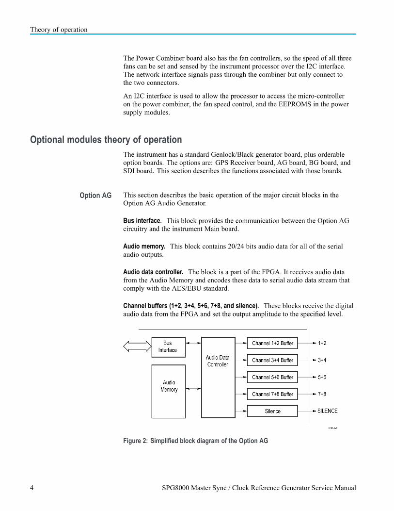
Option AG This section describes the basic operation of the major circuit blocks in theOption AG Audio Generator.
Bus interface. This block provides the communication between the Option AGcircuitry and the instrument Main board.
Audio memory. This block contains 20/24 bits audio data for all of the serialaudio outputs.
Audio data controller. The block is a part of the FPGA. It receives audio datafrom the Audio Memory and encodes these data to serial audio data stream thatcomply with the AES/EBU standard.
Channel buffers (1+2, 3+4, 5+6, 7+8, and silence). These blocks receive the digitalaudio data from the FPGA and set the output amplitude to the specified level.
Figure 2: Simplified block diagram of the Option AG
4 SPG8000 Master Sync / Clock Reference Generator Service Manual

Theory of operation
Option BG theory ofoperation
This section describes the basic operation of the major blocks in the Option BGcircuitry.
Bus interface. This block provides the communication between the Option BGcircuitry and the instrument Main board.
Sync generator. The block creates the digital data of NTSC/PAL black burstsignal or HDTV trilevel sync signal. When optional memories are added, syncgenerator 3 and 4 can also generate 10 field ID and NTSC/PAL color bar signals.
D/A converter and amp. The block consists of a D/A converter, two amplifiers,and two filters (one is for NTSC/PAL and another is for HD). The D/A converterconverts the digital data from the Sync Generator to an analog signal andreconstructs the signal for output.
Figure 3: Simplified block diagram of the Option BG
Genlock/Black boardtheory of operation
The standard Genlock/Black board provides black, LTC and wordclockgeneration, as well as genlock and VITC/LTC time code input. This subsectiondescribes the basic operation of the major circuit blocks on the standardGenlock/Black board. The next subsection describes the Option GPS Receiverboard circuitry. (See Figure 4.)
Genlock control loop. The rear-panel REF and passive LOOP connectors acceptreference video input. The reference video is then buffered, and drives a syncseparator and an Analog to Digital Converter (ADC). The sync signals allowthe Genlock logic to roughly align the internal sync to the incoming video. Thesync signal also allows the genlock logic to window on the ADC samples fromthe sync edge or the burst. The samples are read by the SW which then "closesthe loop" by writing to the DAC that controls the OCXO. This sets the phaseand frequency of all the internal clocks.
SPG8000 Master Sync / Clock Reference Generator Service Manual 5

Theory of operation
All access to this circuitry occurs through the address and data busses, shown asthe CPU I/O bus. The interface is a PLD on the GPS board, which is the centralcontrol interface for MCU data transactions to and from the GPS circuitry.
MTOD clock. The Master Time of Day (MTOD) clock contains the precise currenttime, which is phase locked to the selected time source. The MTOD is used for alltime code generation and positioning of the frame reset pulses.
Outputs. The three Black Generation Engines and the four LTC engines eachreceive one of three frame reset pulses from the mainframe, which lock the videoframes in all engines to exact references based on MTOD.
So that multiple units can have the same phase when locked to GPS, GLONASSor PTP the instrument times the frame pulses to an “Epoch.” This means that allthe signals are timed as if they started at a common time in the past, the "Epoch."The epoch may be selected as GMT midnight (00:00:00) on Jan 1st of either1958 or 1970. The PTP standards specify the 1970 value. The video sequencesgenerated by Option GPS are set to the correct time by calculating the totaltime from the selected epoch to the present, and adjusting the frame reset pulsesaccordingly. The frame reset pulses are used to reset the video generation outputsstart position in time.
Option GPS provides 1 GPI (General Purpose Interface) input and 2 GPI outputsthat you can set up for event triggering or detection. These are under SW controlthrough the FPGA registers.
48 kHz word clock generator. The base black generator generates a 48 kHz clock(word clock) signal. You can configure this clock through the user interface for1 V or 5 V.
VITC time code reader. The VITC time code reader operates on the same ADCdata as the genlock. This data is processed to extract the VITC bits and check forvalid CRC and continuity. When valid time code is detected, the SW reads thetime values from the reader circuits.
LTC time code reader. LTC1 can be configured as an input. An ADC digitizesthe LTC input and FPGA logic decodes the time data. The CPU reads the timedata and sets the MTOD.
6 SPG8000 Master Sync / Clock Reference Generator Service Manual

Theory of operation
Figure 4: Simplified block diagram of the Genlock/Black and Option GPS circuitry
SPG8000 Master Sync / Clock Reference Generator Service Manual 7
Theory of operation
Option GPS theory ofoperation
Option GPS is a receiver board, which is mounted on the standard Genlock/Blackboard. The option adds GPS and GLONASS input capability. Refer to theGenlock/Black block diagram to view the Option GPS interconnections. (SeeFigure 4.)
GPS receiver types Earlier versions of the GPS module can receive only GPS signals. Later versionsof the GPS module can receive both GPS and GLONASS signals. If your modulehas the GPS/GLONASS receiver, use the REFERENCE menu to configure themodule for the type of signal you are using.
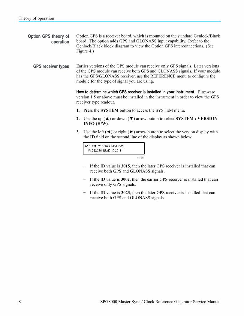
How to determine which GPS receiver is installed in your instrument. Firmwareversion 1.5 or above must be installed in the instrument in order to view the GPSreceiver type readout.
1. Press the SYSTEM button to access the SYSTEM menu.
2. Use the up () or down () arrow button to select SYSTEM : VERSIONINFO (H/W).
3. Use the left () or right () arrow button to select the version display withthe ID field on the second line of the display as shown below.
If the ID value is 3015, then the later GPS receiver is installed that canreceive both GPS and GLONASS signals.
If the ID value is 3002, then the earlier GPS receiver is installed that canreceive only GPS signals.
If the ID value is 3023, then the later GPS receiver is installed that canreceive both GPS and GLONASS signals.
8 SPG8000 Master Sync / Clock Reference Generator Service Manual

Theory of operation
Option GPS receiver loop. The Option GPS Receiver board block is a Trimblemodule, which can track up to 21 satellites, depending on constellation mode, andextract and average the time information from them.
The GPS/GLONASS receiver produces a pulse at the rate of 1 pulse per second(PPS) which is compared to a locally generated pulse per second (Local 1 PPS)in the Phase Detector block. The output from the Phase Detector contains aQuantization Error due to the time sampling method used in the GPS Receiverboard. The GPS/GLONASS receiver also produces a serial data stream detailingthe error (which can be up to 20 ns) that is arithmetically removed from the phasedetector output (the Quantize Correction path). This corrected phase detectoroutput can be seen on the diagnostic display.
The corrected phase is first filtered in the averaging and loop control block, andthen read by software. The software then writes this to a synthesizer on theSPG8000 Main board to control the frequency of the mainframe master 54 MHzclock. This frequency control value can also be seen on the diagnostic display.
The mainframe 54 MHz oscillator clocks the Master Time of Day (MTOD)counter. This completes the loop, spread over the two boards, locking themainframe synthesizer and MTOD counter to the incoming GPS or GLONASSsignal.
Antenna connector. Option GPS requires an external antenna to receive the GPSor GLONASS time signals. A GPS-only receiver can receive signals from up to12 satellites; a GPS/GLONASS receiver has 32 channels and can receive signalsfrom up to 21 satellites. (See page 8, How to determine which GPS receiver isinstalled in your instrument.)
The antenna connector applies these signals to the GPS Receiver board. Forinformation about antenna requirements and installation, refer to the SPG8000Quick Start User Manual, which is listed in the Product documentation table.(See Table i.)
SPG8000 Master Sync / Clock Reference Generator Service Manual 9

Theory of operation
Option SDI theory ofoperation
This section describes the basic operation of the major circuit blocks in theOption SDI. The discussions relate to the Block Diagram. (See Figure 5.)
There is some circuitry on the Option SDI Main circuit board that is not used.Unused circuitry is not represented in the block diagram, nor is it discussed inthis theory of operation.
Figure 5: Simplified block diagram of Option SDI
Overview. The Option SDI has three circuit boards: the Option SDI board, whichmounts horizontally and contains the bulk of the circuitry, and two small outputboards. These output boards plug into the SDI board vertically and provide the rearBNC connections and the circuits required to buffer the high-speed output signals.
The heart of the Option SDI generator is an FPGA, with other circuits that providesupport and ancillary functions. For signal generation, the FPGA creates theoutput signal such as color bars or a ramp. For some signals, the information tocreate the signals is completely contained within the FPGA. For other signals,data from the memories is used as well. Serialization and scrambling is alsodone in the FPGA.
10 SPG8000 Master Sync / Clock Reference Generator Service Manual

Theory of operation
FPGA and associated circuits. A Programmable Logic Device (PLD) configuresthe FPGA by loading a file from the Flash at power up. This configures the FPGAfor normal operation; there is a separate file for calibration.
The CPU interface connects to both the PLD and FPGA. During SW upgrade,the Flash files are loaded from the mainframe through the PLD. The FPGA usesthe CPU connection to access the control registers.
Signal generation. The FPGA contains horizontal and vertical counters, whichcreate the raster structure for the selected signal. For most test signals, thesecounters drive the FPGA elements that create the actual video signals such ascolor bars or flat field, along with the EAV and SAV info and CRCs, if appropriate.The video signals are then scrambled, serialized, and sent at 270 Mb/s, 1.5 Gb/s or3 Gb/s from the FPGA to the output boards.
When generating frame picture signals, similar horizontal and vertical countersaccess the DDR memory for the given channel. In this mode, the data from theuser's picture file is used to create the test signal. This data stream is combinedwith the standard test signal stream to add the other required elements, and theresult is then serialized.
For logo overlay, the frame picture system is used, but only for a portion of theimage. The user logo information is read from the DDR memory, and blendedwith the test signal information.
The circle and text overlay functions are generated from the SRAM for eachchannel. This data is blended with the active portion of the test signal or framepicture information to produce the combined signal information.
Clocks and frames. The SPG8000 circuitry provides three frame pulse signals.The actual frame signal used is the appropriate one for the rate of the signal beinggenerated. The selected input frame resets the counters in the FPGA, establishingthe correct video timing.
The SPG8000 circuitry also provides a 54 MHz clock for generator mode. This54 MHz clock drives a DDS in the FPGA to create a digitized sine wave, whichis then applied to the flexible generator clock circuit. Depending on the outputformat the flexible clock output is at either 148.5 MHz or 148.35 MHz. This clockis fed back to the FPGA to drive the generator core functions, and sent to theFPGA serializer clock inputs and the trigger output multiplexer.
The 54 MHz input clock also registers the input frame pulse. After it isregistered at 54 MHz, it must cross to the 148.5 MHz domain. For this to workdeterministically the phase of the two clocks is automatically controlled. Thestatus of this automatic control system is shown in the diagnostic menu as DDS0phase (channel 1) and DDS1 phase (channel 2).
SPG8000 Master Sync / Clock Reference Generator Service Manual 11
Theory of operation
SDI output boards. The two SDI Output boards (one for each output channel) taketwo channels from the FPGA serializers and buffers them to drive 75 Ω cable. Theoutput level is set by nonvolatile electronic potentiometers on the output board, sothe calibration is captured in the board.
Power supplies. This option has three switching supplies, and several linearsupplies. Most of the power comes in as 5 V and is converted to the voltageneeded by the switching supplies. The SPG8000 circuitry provides a smallamount of 3.3 V for the processor interface, but the bulk of the 3.3 V used on theboard is produced by the switching supply.
There are also 1.8 V and 1.2 V supplies, which are used for the memory andFPGA cores.
12 SPG8000 Master Sync / Clock Reference Generator Service Manual

Adjustment proceduresThis section provides procedures for the adjustments that can be performed bytrained service technicians.
CAUTION. All Adjustment procedures are to be performed only by trained servicetechnicians.
NOTE. Master clock. There are two methods for adjusting the frequency of themaster clock. You can use a frequency signal generator, or if Option GPS isinstalled, you can lock the master clock to a GPS or GLONASS signal. Proceduresfor both methods are included in this section.
If your SPG8000 generator has Option GPS installed, you need to use GPS orGLONASS to adjust the master clock frequency. In this case, you can adjust theclock while the instrument is in operation, which avoids any system downtime orany warm-up period.
If your instrument does not have Option GPS installed, you must remove theinstrument from service in order to adjust the master clock using a frequencygenerator.
Earlier versions of the GPS module can receive only GPS signals. Later versionsof the GPS module can receive both GPS and GLONASS signals. (See page 8,How to determine which GPS receiver is installed in your instrument.)
Adjust master clock using a frequency signal generatorUse this procedure to adjust the frequency of the master clock if you do not haveOption GPS installed in the instrument under test. This will require a referenceSPG8000 with Option GPS installed (or equivalent test equipment).
Warm-up period. Allow a 20 minute warm-up time in a +20 °C to +30 °Cenvironment before making this adjustment. The reference SPG8000 unit mustbe hooked to an external antenna, GPS or GLONASS signal during the warm-upperiod.
Adjustments done before the operating temperature has stabilized may causeerrors in performance. In addition, the signal generators require appropriatewarm-up time to meet the frequency accuracy.
SPG8000 Master Sync / Clock Reference Generator Service Manual 13

Adjustment procedures
Required equipment. The following table lists the equipment required to adjustthe master clock frequency using a frequency signal generator.
Table 1: Equipment required to adjust the master clock using a signal generator
Item No. Minimum requirement Recommended equipment
Frequency standard 1 Frequency: 10 MHz ±1×10⁻⁹
Amplitude: 8 dBm
A reference Tektronix SPG8000, withOption GPS installed and locked toGPS, GLONASS or equivalent
Spectracom/Pendulum 6689
75 Ω BNC cable 1 Length: 42 inches Tektronix part number 012-0074-00
Procedure Perform the following procedure to adjust the master clock frequency usinga frequency standard.
1. Set the output of the frequency standard as follows:
Frequency: 10.000000 MHzOutput level: 8 dBm
2. Use the 75 Ω BNC cable to connect the rear-panel REF connector to theoutput of the frequency standard as shown in the following figure, and attacha 75 Ω terminator to the REF loop-through connector.
NOTE. You can use a second SPG8000, with Option GPS installed, to produce the10 MHz frequency standard.
In this case, check that the Option GPS is locked to a GPS or GLONASS signal infine mode. Configure the Black 3 output to supply a 10 MHz sine wave. Connectthe Black 3 output to the rear-panel REF connector on the second SPG8000.
Figure 6: Adjusting the master clock frequency using a frequency standard
3. Restart the instrument in Factory mode. (See page 105, To power up infactory mode.)
4. Let the instrument warm up for 20 minutes before proceeding.
14 SPG8000 Master Sync / Clock Reference Generator Service Manual

Adjustment procedures
5. Set the reference source to CW as follows:
a. Press the REF button to display the REFERENCE menu.
b. Press the left () or right () arrow button to select CW, and then pressthe ENTER button.
6. Calibrate the oven system:
a. Press the SYSTEM button.
b. Press the up () or down () arrow button to selectCALIBRATE : OVEN.
c. Press the ENTER button.
d. A message will be displayed asking you to verify that you want to executethe calibration. Press the ENTER button to proceed with the calibration.
e. Verify that the message CALIBRATION result = xxxxxxx is displayed.The result should be seven characters near the value of 2,097,152. Pressthe ENTER button to exit the calibration mode.
7. Verify the calibration:
a. Press the SYSTEM button.
b. Press the up () or down () arrow button to select DIAGNOSTICS.
c. Press the ENTER button.
d. Press the up () or down () arrow button to selectDIAGNOSTICS : CALIBRATION.
e. Check that the CAL value is less than 2.5 e-6.
NOTE. If the CAL value is greater than 2.6 e-6, the oscillator oven may need tobe serviced.
SPG8000 Master Sync / Clock Reference Generator Service Manual 15
Adjustment procedures
Adjust master clock while locked to GPSUse this procedure, you can adjust the clock while the instrument is in operation,which avoids any system downtime.
NOTE. Earlier versions of the GPS module can receive only GPS signals. Laterversions of the GPS module can receive both GPS and GLONASS signals. (Seepage 8, How to determine which GPS receiver is installed in your instrument.)
Warm-up period. Allow a 20 minute warm-up time in a +20 °C to +30 °Cenvironment before making this adjustment. The instrument must be hooked to anexternal antenna or GPS signal during the warm-up period.
Table 2: Equipment required to adjust the master clock while locked to GPS
Item No.Minimumrequirement Recommended equipment
GPS or GLONASS antennafeed with good signal level
1 Less than 5 dBattenuation since lastamplifier
Trimble Bullet III, 5V, 35 dB gain,antenna with F-connector, orequivalent.
Cable: up to 200 ft Belden 1694A, or equivalent, with anF connector on one end and a BNC connector on the other end.
Procedure. Perform the following procedure to set the internal frequency of theinternal oscillator. This adjustment stores the current frequency of the oscillatorwhile it is locked to a GPS, GLONASS or a reference signal, to be used whenin Internal mode. It can be done without any disruption to operation and is bestdone in the operating environment of the instrument.
1. Verify that the GPS Constellation type is set to GPS & GLONASS:
NOTE. You need to perform this step only if your Option GPS module has aGPS/GLONASS receiver. (See page 8, How to determine which GPS receiver isinstalled in your instrument.)
a. Press the REF button to access the REFERENCE menu.
b. Use the up () or down () arrow button to select GPSCONSTELLATION.
c. Use the left () or right () arrow button to select GPS & GLONASS.
d. Press the ENTER button to make the selection.
2. Verify that the instrument has warmed up for at least 20 minutes, with theexternal antenna GPS and/or GLONASS signal connected.
3. Press the STATUS button.
16 SPG8000 Master Sync / Clock Reference Generator Service Manual

Adjustment procedures
4. Press the up () or down () arrow button to select STATUS : GPS.
5. Check that the signal status shows Locked.
6. Calibrate the oven system:
a. Press the SYSTEM button.
b. Press the up () or down () arrow button to selectCALIBRATE : OVEN.
c. Press the ENTER button.
d. A message will be displayed asking you to verify that you want to executethe calibration. Press the ENTER button to proceed with the calibration.
e. Verify that the message CALIBRATION result = xxxxxxx is displayed.The result should be seven characters near the value of 2,097,152. Pressthe ENTER button to exit the calibration mode.
7. Verify the calibration:
a. Press the SYSTEM button.
b. Press the up () or down () arrow button to select DIAGNOSTICS.
c. Press the ENTER button.
d. Press the up () or down () arrow button to selectDIAGNOSTICS : CALIBRATION.
e. Check that the CAL value is less than 2.5 e-6.
NOTE. If the CAL value is greater than 2.6 e-6, the oscillator oven may need tobe serviced.
SPG8000 Master Sync / Clock Reference Generator Service Manual 17

Adjustment procedures
Adjust Option BGAdjustments in the Option BG are for the output offset, output gain, and chromagain.
Warm-up period. Allow a 20 minute warm-up time in a +20 °C to +30 °Cenvironment before making these adjustments. Adjustments done before theoperating temperature has stabilized may cause errors in performance.
Required equipment. The following table lists the equipment required to adjustthe output offset, output gain, and chroma gain.
Table 3: Adjusting Option BG
Item No. Minimum requirement Recommended equipment
TV signal generator platform 1 Tektronix SPG8000 with Option BGinstalled
Digital multimeter 1 5 1/2 digits FLUKE 8842A
Oscilloscope 1 Bandwidth: 1 GHz or higher
75 Ω input
Tektronix DPO70404C with TekConnectTCA-75 adapter
75 Ω BNC cable 1 Length: 42 inches Tektronix part number 012-0074-00
75 Ω coaxial terminator 1 75 Ω ±0.1% Tektronix part number 011-0102-03
BNC T connector 1 Tektronix part number 103-0030-00
BNC female to dual bananaadapter
1 Tektronix part number 103-0090-00
18 SPG8000 Master Sync / Clock Reference Generator Service Manual

Adjustment procedures
Adjust the Option BGoutput offset and gain
WARNING. To avoid serious injury, do not touch exposed connectors orcomponents when operating the SPG8000 with the top cover removed. Dangerouspotentials exist at several points within the instrument.
1. Remove the top cover of the SPG8000. (See page 46, Top cover.)
2. Locate the variable resistors on the BG circuit board. (See Figure 7.)
Figure 7: Variable resistors on the Option BG board
3. Use the 75 Ω BNC cable, BNC T connector, 75 Ω coaxial terminator, andBNC female-to-dual banana adapter to connect the BLACK 4 connector tothe input connector on the digital multimeter. (See Figure 8.)
Figure 8: Adjusting the Option BG output offset and gain
4. Restart the instrument in Factory mode. (See page 105, To power up infactory mode.)
SPG8000 Master Sync / Clock Reference Generator Service Manual 19

Adjustment procedures
5. Select the DAC Offset (0 V DC) calibration signal for the Option BG outputsas follows:
a. Press the BLACK button until you see BLACK 4 : FORMAT on thedisplay.
b. Use the left () or right () arrow button to select NTSC.
c. Press the ENTER button.
d. Use the up () arrow button to select CALIBRATION.
e. Use the left () or right () arrow button to select OFFSETCALIBRATION.
f. Press the ENTER button.
g. Use the left () or right () arrow button to selectCALIBRATION : Offset DAC 715 (0 V).
h. Press the ENTER button.
i. Press the BACK button.
j. Repeat this step until you have selected the calibration signal for theBLACK 4, BLACK 5, CMPST 1, and CMPST 2 outputs, using theCMPST button to view the Composite signal menus.
6. Locate variable resistor R491 on the BG circuit board. (See Figure 7.)
7. Adjust R491 so that the output offset is 0 V ±1 mV.
8. Change the BNC cable connection from the BLACK 4 connector to theBLACK 5 connector.
9. Locate variable resistor R591 on the BG circuit board. (See Figure 7.)
10. Adjust R591 so that the output offset is 0 V ±1 mV.
11. Change the BNC cable connection from BLACK 5 connector to the CMPST 1connector.
12. Locate variable resistor R691 on the BG circuit board.
13. Adjust R691 so that the output offset is 0 V ±1 mV.
14. Change the BNC cable connection from the CMPST 1 to the CMPST 2connector.
15. Locate variable resistor R791 on the BG circuit board.
16. Adjust R791 so that the output offset is 0 V ±1 mV.
20 SPG8000 Master Sync / Clock Reference Generator Service Manual

Adjustment procedures
17. Select the DAC Gain (700 mV DC) calibration signal for the Option BGoutputs as follows:
a. Press the BLACK button until you see BLACK 4 : FORMAT on thedisplay.
b. Use the left () or right () arrow button to select NTSC.
c. Repeat for the BLACK 5 output.
d. Press the up () arrow button to select CALIBRATION.
e. Press the left () or right () arrow button to select AmplitudeCalibration.
f. Press the ENTER button.
g. Press the left () or right () arrow button to select DAC Gain(700 mV DC).
h. Press the BACK button.
i. Repeat parts a through h of this step to select the calibration signal for theBLACK 5, CMPST 1, and CMPST 2 outputs, using the CMPST button toselect the Composite outputs.
18. Locate variable resistor R481 on the BG circuit board. (See Figure 7.)
19. Adjust R481 so that the output level is 700 mV ±1 mV.
20. Change the BNC cable connection from the BLACK 4 connector to theBLACK 5 connector.
21. Locate variable resistor R581 on the Option BG circuit board. (See Figure 7.)
22. Adjust R581 so that the output level is 700 mV ±1 mV.
23. Change the BNC cable connection from the BLACK 5 connector to theCMPST 1 connector.
24. Locate variable resistor R681 on the BG circuit board. (See Figure 7.)
25. Adjust R681 so that the output level is 700 mV ±1 mV.
26. Change the BNC cable connection from the CMPST 1 connector to theCMPST 2 connector.
27. Locate variable resistor R781 on the BG circuit board. (See Figure 7.)
28. Adjust R781 so that the output level is 700 mV ±1 mV.
SPG8000 Master Sync / Clock Reference Generator Service Manual 21

Adjustment procedures
Adjust the Option BGchroma gain
WARNING. To avoid serious injury, do not touch exposed connectors orcomponents when operating the SPG8000 with the top cover removed. Dangerouspotentials exist at several points within the instrument.
1. Remove the top cover of the SPG8000. (See page 46, Top cover.)
2. Locate the variable resistors on the BG circuit board. (See Figure 7.)
3. Use the 75 Ω BNC cable to connect the CMPST 1 connector on the SPG8000to the CH 1 connector on the oscilloscope, as shown. (See Figure 9.)
Figure 9: Adjusting chroma gain
4. Select the PAL 75% Color Bars (100% White) signal for CMPST 1 andCMPST 2 as follows:
a. Press the CMPST button until you see CMPST 1 : Format in the display.
b. Press the right () arrow button to select PAL
c. Press the ENTER button.
d. Press the down () arrow button to view the CMPST 1 : TEST SIGNALmenu.
e. Press the right () arrow button to select 75% Color Bars (100%White).
f. Press the ENTER button.
g. Repeat for the CMPST 2 output.
22 SPG8000 Master Sync / Clock Reference Generator Service Manual

Adjustment procedures
5. Set the oscilloscope controls as follows:
Vertical: 100 mV / div
Sample depth: 100 K
Horizontal: 2.5 μs / div
Trigger position: 50%
Vert offset: 700 mV
Trigger: 720 mV, rising edge
Hold-off: 63 μs
6. After you see a stable trace on the oscilloscope, change the Vertical setting to5 mV / div.
7. Locate the flat bar followed by the burst packets for yellow and cyan asshown in the following figure.
Figure 10: Triggered display for adjusting the Option BG chroma gain
8. Locate variable resistor R927 on the BG circuit board. (See Figure 7.)
9. Adjust R927 to match the level of the first chroma packet to the preceding75% flat bar.
10. Change the BNC cable connection from the CMPST 1 connector to theCMPST 2 connector.
11. Locate variable resistor R977 on the BG circuit board. (See Figure 7.)
12. Adjust R977 to match the first chroma packet to the level of the preceding75% flat bar.
SPG8000 Master Sync / Clock Reference Generator Service Manual 23
Adjustment procedures
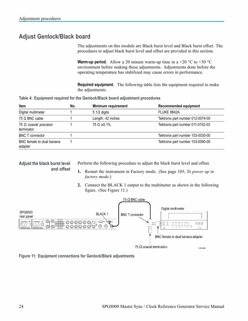
Adjust Genlock/Black boardThe adjustments on this module are Black burst level and Black burst offset. Theprocedures to adjust black burst level and offset are provided in this section.
Warm-up period. Allow a 20 minute warm-up time in a +20 °C to +30 °Cenvironment before making these adjustments. Adjustments done before theoperating temperature has stabilized may cause errors in performance.
Required equipment. The following table lists the equipment required to makethe adjustments.
Table 4: Equipment required for the Genlock/Black board adjustment procedures
Item No. Minimum requirement Recommended equipment
Digital multimeter 1 5 1/2 digits FLUKE 8842A
75 Ω BNC cable 1 Length: 42 inches Tektronix part number 012-0074-00
75 Ω coaxial precisionterminator
1 75 Ω ±0.1% Tektronix part number 011-0102-03
BNC T connector 1 Tektronix part number 103-0030-00
BNC female to dual bananaadapter
1 Tektronix part number 103-0090-00
Adjust the black burst leveland offset
Perform the following procedure to adjust the black burst level and offset.
1. Restart the instrument in Factory mode. (See page 105, To power up infactory mode.)
2. Connect the BLACK 1 output to the multimeter as shown in the followingfigure. (See Figure 11.)
Figure 11: Equipment connections for Genlock/Black adjustments
24 SPG8000 Master Sync / Clock Reference Generator Service Manual

Adjustment procedures
3. Press the BLACK button until you see BLACK 1 on the display.
4. Set the Black level:
a. Press the up () or down () arrow button to select CALIBRATION.
b. Press the left () or right () arrow button to selectCALIBRATION : AMPLITUDE.
c. Press the ENTER button.
d. Press the left () or right () arrow button to select the 0 V signal.
e. Make a note of the voltmeter reading.
f. Press the left () or right () arrow button to select the 700 mV signal.
g. Make a note of the voltmeter reading.
h. Subtract the voltage measured in part e of this step (0 mV setting) fromthe voltage measured in part f of this step (700 mV setting).
i. If the result is <698 mV or >702 mV, use the up () or down () arrowbuttons to adjust the gain.
j. Repeat parts d through i of this step until the difference between the twosignals is 700 mV ± 2 mV.
k. Press the ENTER button to save the setting and exit the amplitudecalibration menu.
5. Set Black offset:
a. Proceeding from the previous step, use the left () or right () arrowbutton to select CALIBRATION : OFFSET.
b. Press the ENTER button.
c. Use the left () or right () arrow button to select the 0 V signal.
d. Measure the offset voltage.
e. If necessary, use the up () or down () arrow buttons to adjust theoffset voltage to 0 V ±5 mV.
f. Press the ENTER button to save the setting and exit the offset calibrationmenu.
6. Move the cable to the next output and repeat steps 3 through 5 for the BLACK2 and BLACK 3 outputs.
SPG8000 Master Sync / Clock Reference Generator Service Manual 25

Adjustment procedures
Adjust Option SDIThere is only one adjustment for Option SDI. This adjustment sets the SDI outputamplitude. Perform this adjustment for each channel if the instrument fails theSDI Output Amplitude portion of the performance verification procedure. Thisprocedure replicates part of that procedure.
Warm-up period. Allow a 20 minute warm-up time in a +20 °C to +30 °Cenvironment before making these adjustments. Adjustments done before theoperating temperature has stabilized may cause errors in performance.
Required equipment. The following table lists the equipment required to makethe adjustments.
Table 5: Equipment required for the Option SDI adjustment procedures
Item No. Minimum requirement Recommended equipment
TV signal generator platform 1 Tektronix SPG8000 with Option SDIinstalled
Digital signal analyzer 1 Digital signal analyzer with a 20 GHzelectrical sampling module and a probeinterface module
Tektronix DSA8200 with an 80E04electrical sampling module and an80A03 Tek Connect Probe Interfacemodule
Stable 10 kHz sine wavegenerator
1 CW sine wave with 800 mVp-p ±5%into 75 Ω, THD < 60 dBc, 10 kHz, and<50 mV DC offset
Tektronix AFG3101
Tekconnect 75 Ω to 50 Ωadapter with BNC inputconnector
1 Tektronix TCA75
Precision RMS voltmeter 1 Keithley 2700 DMM
6 dB SMA attenuator 1 Tektronix part number 015-1001-01
SMA (male) to BNC (female)adapter
Tektronix part number 015-0554-00
1 m (3 ft.) BNC to BNChigh-bandwidth cable
1 Belden 1694, MarkerTek 1694-B-B-3
1 m (3 ft.) BNC to BNC 50 Ωcable
1 Tektronix part number 012-0057-01
75 Ω precision terminator 1 75 Ω ±0.1% Tektronix part number 011-0102-03
BNC T connector 1 Tektronix part number 103-0030-00
BNC female to dual bananaadapter
1 Tektronix part number 103-0090-00
26 SPG8000 Master Sync / Clock Reference Generator Service Manual

Adjustment procedures
SDI output amplitudeadjustment table
Print this table for use during the adjustment procedure.
Table 6: SDI output amplitude
Minimum Value Maximum
Characterization
DMM Measurement(typically 0.2880 V)
— — — —
Oscilloscope Cycle RMS(typically 116 mV)
— — — —
Oscilloscope Cycle Mean(typically 1 mV)
— — — —
Sine wave RMS amplitude(typically 116 mV)
— —
Attenuation Factor 2.35 2.55
ValueAdjustment Record
Minimum Before adjustment After adjustment Maximum
SDI 1A amplitude
Measured value (μ)with attenuation
776 mV 824 mV
SDI 1B amplitude
Measured value (μ)with attenuation
776 mV 824 mV
SDI 2A amplitude
Measured value (μ)with attenuation
776 mV 824 mV
SDI 2B amplitude
Measured value (μ)with attenuation
776 mV 824 mV
SPG8000 Master Sync / Clock Reference Generator Service Manual 27

Adjustment procedures
Characterize the testsystem amplitude
Before adjusting the SDI Output Amplitude, you must first characterize the testsystem amplitude.
There are three parts to the amplitude characterization:
Part A: Sets up a characterization reference to the DMM.
Part B: Set up the DSA oscilloscope.
Part C: Characterizes the test system.
Part A: characterize the reference against the DMM.
1. Connect the equipment as follows:
a. Connect one end of a 1 m high bandwidth cable to the AFG3101 output.
b. Connect the other end of the 1 m cable to the BNC T.
c. Connect the BNC T to a BNC to banana adapter.
d. Connect the other end of the BNC T to a precision terminator.
e. Connect the end of the banana adapter to the input of the DMM.
2. Set the AFG3101 to output a sine wave into a load impedance of 75 Ω.
3. Set the AFG3101 to a 10 kHz output into a load impedance of 75 Ω.
4. Set the AFG3101 to a 800 mVp-p output into a load impedance of 75 Ω.
5. Check that the output of the AFG3101 is On.
6. Set the DMM to measure AC voltage using a medium filter setting. Set therange to allow for four digits of RMS amplitude.
7. Record the DMM measurement in the SDI output amplitude table. (SeeTable 6 on page 27.)
28 SPG8000 Master Sync / Clock Reference Generator Service Manual

Adjustment procedures
Part B: Set up the digital signal analyzer.
CAUTION. Electrostatic discharge can damage the oscilloscope modules. Toprevent damage, always work in a static free environment and discharge thestatic voltage from your body by wearing a grounded antistatic wrist strap whilehandling these modules.
1. Install the 80A03 output cable into the Channel 1/2 slot of the oscilloscope.
2. Install the 80E04 sampling head into the 80A03 adapter and connect the twousing the SMA cables.
3. Install the TCA-75 into the left port of the 80A03.
4. Install the TCA-BNC into the right port of the 80A03.
5. If needed, press the Default Settings button on the oscilloscope.
6. Press the Channel 1 button on the 80E04 sampling head to activate Channel 1.
Part C: Characterize the test system.
1. Connect the equipment as follows:
a. Connect the AFG3101 output to 1 m high bandwidth cable.
b. Connect the other end of the cable to a TCA-75.
c. Connect the TCA-75 to the 80A03 in the oscilloscope and plug-in.
d. Connect a 50 Ω cable from the AFG3101 trigger output.
e. Connect the other end of the 50 Ω cable to the BNC to SMA adapter.
f. Connect the SMA adapter to the 6 dB pad.
g. Connect the 6 dB pad to the trigger direct input on the oscilloscope.
2. Keep the AFG3101 at the same output as in Part A of this test.
3. Set the oscilloscope as follows:
Time/Div: 20 μsVolts/Div: 50 mVAveraging: 16Record Length: 4000 points
4. On the oscilloscope, select measurement 1 and then pulse amplitude andset it to measure Cycle RMS.
5. On the oscilloscope, select measurement 2 and then pulse amplitude and setit to measure Cycle Mean.
SPG8000 Master Sync / Clock Reference Generator Service Manual 29

Adjustment procedures
6. Record the Cycle RMS and Cycle Mean values in the SDI output amplitudetable.
7. Calculate the corrected RMS amplitude of the sine
wave:
8. Record the result in the test record.
9. Calculate the total attenuation factor for the system. This is the DMMmeasurement divided by the corrected RMS sine wave amplitude.
10. Record the attenuation factor value in the SDI output amplitude table.
11. Enter the attenuation factor value into the oscilloscope:
a. On the oscilloscope, press the SETUP DIALOG button.
b. Select the “Vert” tab from the top of the setup page.
c. Select the “External Attenuation” box, and enter the attenuation factorcalculated in step 9 above.
Adjust the SDI outputamplitude
1. Restart the instrument in Factory mode. (See page 105, To power up infactory mode.)
2. Press the SDI button until SDI 1 appears.
3. Connect a 1 m high-bandwidth cable from the SDI 1A output of the moduleto the TCA75 BNC on the oscilloscope adapter.
4. Connect a 50 Ω cable from the SDI 1B output (through the BNC to SMAadapter, with or without the 6 dB pad) to the trigger direct input on a samplingoscilloscope.
5. Press the SDI button until SDI7[x-1]: STATUS appears.
6. Use the up () or down () arrow button to select CALIBRATION.
7. Press the ENTER button.
8. Press the right () arrow button to select 20 Bits Square.
9. Press the ENTER button.
10. If necessary, set the oscilloscope as follows:
Time/Div: 2 nsVolts/Div: 100 mVAveraging: 16Record Length: 4000 points
30 SPG8000 Master Sync / Clock Reference Generator Service Manual

Adjustment procedures
11. On the oscilloscope, select Measurement 3, Pulse-Amplitude, and thenAmplitude to measure the amplitude on the flat part of the long pulse.
12. Right click on the measurement readout, and select Show Statistics and ShowAnnotations from the pop-up menu.
13. Note the expected average value, which is indicated by the letter μ, displayedon the oscilloscope.
14. Press the Clear Data button on the oscilloscope and wait about 5 secondsbefore proceeding to the next step.
15. Record the average value, which is indicated by the letter μ, in the Signal 1Aamplitude row Before adjustment value column of the SDI output amplitudetable.
NOTE. If you entered the attenuation factor into the oscilloscope at the endof the amplitude characterization procedure, the oscilloscope will display themultiplication result.
16. If adjustment is necessary, press the up () or down () arrow button, andthen press the ENTER button, to activate the adjustment mode.
17. Press the Clear Data button on the oscilloscope and wait about 5 secondsbefore proceeding to the next step.
18. Press the up () or down () arrow button to change the amplitude to theexpected average value noted in step 13.
19. Repeat steps 17 and 18 until the average measured value (μ) is within 1 mVof 800 mV, and then press the ENTER button to save the new amplitudecalibration value.
20. Record the new measured attenuation corrected value in the Signal 1Aamplitude row After adjustment value column of the SDI output amplitudetable.
21. Press the Back button to exit the Channel 1: Top Calibration mode.
22. Connect the SDI 1A output to the trigger input of the DSA using the1 meter 50 Ω cable. Connect the SDI 1B output to the TCA-75 using thehigh-bandwidth 75 Ω cable.
23. Use the left () or right () arrow buttons to select Channel 1: Bottomto adjust the SDI 1B output.
24. Press the ENTER button.
25. Press the right () arrow button to select 20 Bits Square.
26. Press the ENTER button.
27. Repeat steps 15 through 21 for the SDI 1B output.
SPG8000 Master Sync / Clock Reference Generator Service Manual 31

Adjustment procedures
28. Move the 1 m high-bandwidth cable from the SDI 1B output to the SDI 2Aoutput.
29. Move the 50 Ω cable from the SDI 1 A output to SDI 2 B.
30. Press the left () or right () arrow buttons to select Channel 2: Top toadjust the Signal 2A output.
31. Press the ENTER button.
32. Press the right () arrow button to select 20 Bits Square.
33. Repeat steps 15 through 21 for the Signal 2A output.
34. Move the 1 m high-bandwidth cable from the SDI 2A output to the SDI 2Boutput and swap the trigger input to connect to SDI 2A
35. Use the left () or right () arrow buttons to select Channel 2: Bottom.
36. Press the ENTER button.
37. Press the right () arrow button to select 20 Bits Square.
38. Press the ENTER button.
39. Repeat steps 15 through 21 for the SDI 2B output.
40. Cycle the power on the SPG8000 to return the generator to normal operatingmode.
32 SPG8000 Master Sync / Clock Reference Generator Service Manual

MaintenanceIf your instrument does not function properly, troubleshooting and correctivemeasures should be taken immediately to prevent additional problems.
NOTE. Contact your local Tektronix representative for information on where toreturn your instrument if it requires repair during the warranty period.
This section contains information needed to safely and effectively service theSPG8000 generator to the module level.
To isolate a failure, use the fault isolation procedures found in the troubleshootingsection. To remove and replace any failed module, follow the instructions in theremoval procedure section. Use the replaceable parts list section for part numbersand ordering information for all replaceable modules.
General service informationService prerequisites To prevent personal injury or damage to the instrument, ensure the following
before servicing this instrument:
The procedures in this manual should be performed only by a qualified serviceperson.
Read the General safety summary and the Service safety summary at thebeginning of this manual.
When using this manual for servicing, be sure to follow all warnings, cautions,and notes.
Inspection and cleaning describes how to inspect for dirt and damage and howto clean the exterior and interior of the instrument. (See page 36.)
The Remove and replace procedures describe how to install or remove areplaceable module. (See page 39.)
Performance checkinterval
Generally, the performance check described in the SPG8000 Specifications andPerformance Verification Technical Reference manual should be done every12 months. In addition, a performance check is recommended after repair.
If the SPG8000 generator does not meet performance criteria, repair is necessary.
Terms in the manual Throughout this manual, the term module appears, referring to anyfield-replaceable component or assembly.
SPG8000 Master Sync / Clock Reference Generator Service Manual 33

Maintenance
Tektronix service offerings Tektronix provides service to cover repair under warranty and other services thatmay provide a cost-effective answer to your service needs.
Whether providing warranty repair service or any of the other services listedbelow, Tektronix service technicians are well trained to service the SPG8000generator. They have access to the latest information on improvements to theSPG8000 and the latest new options.
Warranty repair service Tektronix warrants this product for one year from date of purchase. The warrantyappears after the title page in this manual. Tektronix technicians provide warrantyservice at most Tektronix service locations. The Tektronix product catalog listsall worldwide service locations. You can also visit our Web site for serviceinformation: www.tektronix.com.
Self service Tektronix supports repair to the module level by providing module exchange.
Module exchange. This service reduces downtime for repair by allowing you toexchange most modules for remanufactured ones. Each module comes with a90-day service warranty.
For more information. Contact your local Tektronix service center or salesengineer for more information on any of the repair or adjustment services justdescribed.
34 SPG8000 Master Sync / Clock Reference Generator Service Manual

Maintenance
Electrostatic damageprevention
This instrument contains electrical components that are susceptible to damagefrom electrostatic discharge. Static voltages of 1 kV to 30 kV are common inunprotected environments.
Before servicing this product, read the General Safety Summary and the ServiceSafety Summary at the front of the manual, as well as the following ESDinformation.
CAUTION. Static discharge can damage any semiconductor component in thisinstrument.
When performing any service that requires internal access to the instrument,adhere to the following precautions to avoid damaging internal modules and theircomponents due to electrostatic discharge (ESD):
Minimize handling of static-sensitive circuit boards and components.
Transport and store static-sensitive modules in their static protected containersor on a metal rail. Label any package that contains static-sensitive boards.
Discharge the static voltage from your body by wearing a grounded antistaticwrist strap while handling these modules. Service static-sensitive modulesonly at a static-free work station.
Nothing capable of generating or holding a static charge should be allowedon the work station surface.
Handle circuit boards by the edges when possible.
Do not slide the circuit boards over any surface.
Avoid handling circuit boards in areas that have a floor or work-surfacecovering capable of generating a static charge.
SPG8000 Master Sync / Clock Reference Generator Service Manual 35

Maintenance
Inspection and cleaningInspection and Cleaning describes how to inspect for dirt and damage. It alsodescribes how to clean the exterior and interior of the instrument. Inspection andcleaning are done as preventive maintenance. Preventive maintenance, when doneregularly, may prevent malfunction and enhance reliability.
Preventive maintenance consists of visually inspecting and cleaning theinstrument and using general care when operating it.
How often maintenance should be performed depends on the severity of theenvironment in which the instrument is used. A proper time to perform preventivemaintenance is just before any instrument adjustment.
General care The cabinet helps keep dust out and should normally be in place during operation.
WARNING. To prevent injury or death, power off the instrument and disconnect itfrom line voltage before performing any procedure that follows.
Interior cleaning Use a dry, low-velocity stream of air to clean the interior of the chassis. Use asoft-bristle, nonstatic-producing brush for cleaning around components. If youmust use a liquid for minor interior cleaning, use a 75% isopropyl alcohol solutionand rinse with deionized water.
Exterior cleaning Clean the exterior surfaces of the chassis with a dry lint-free cloth or a soft-bristlebrush. If any dirt remains, use a cloth or swab dipped in a 75% isopropyl alcoholsolution. Use a swab to clean narrow spaces around controls and connectors. Donot use abrasive compounds on any part of the instrument that may damaged by it.
CAUTION. Avoid the use of chemical cleaning agents that might damage theplastics used in the instrument. Use only deionized water when cleaning thefront-panel buttons. Use a glass cleaner to clean the LCD. For the rest of theinstrument, use a 75% isopropyl alcohol solution as a cleaner and rinse withdeionized water. Before using any other type of cleaner, consult your TektronixService Center or representative.
36 SPG8000 Master Sync / Clock Reference Generator Service Manual

Maintenance
Inspection – exterior. Inspect the outside of the instrument for damage, wear, andmissing parts, using the following table as a guide. Immediately repair defectsthat could cause personal injury or lead to further damage to the instrument.
Table 7: External inspection checklist
Item Inspect for Repair action
Cabinet, front panel, andcover
Cracks, scratches,deformations, damagedhardware
Repair or replace defectivemodule
Front-panel knobs Missing, damaged, or looseknobs
Repair or replace missing ordefective knobs
Connectors Broken shells, crackedinsulation, and deformedcontacts. Dirt in connectors
Repair or replace defectivemodules. Clear or wash outdirt
Carrying handle and cabinetfeet
Correct operation Repair or replace defectivepart
Accessories Missing items or parts ofitems, bent pins, broken orfrayed cables, and damagedconnectors
Repair or replace damagedor missing items, frayedcables, and defectivemodules
Cracks Replace the LCD assemblyLCD
Dirty Clean with glass cleaner
Inspection – interior. To access the inside of the instrument for inspection andcleaning, you will need to remove the top cover.
Inspect the internal portions of the instrument for damage and wear, using Table4-2 as a guide. Defects found should be repaired immediately.
If any circuit board is repaired or replaced, see if it is necessary to adjust theinstrument. (See Table 8 on page 37.)
CAUTION. To prevent damage from electrical arcing, make sure that circuitboards and components are dry before applying power to the instrument.
Table 8: Internal inspection checklist
Item Inspect for Repair action
Circuit boards Loose, broken, or corrodedsolder connections.Burned circuit boards.Burned, broken, or crackedcircuit-run plating.
Remove and replacedamaged circuit board.
Resistors Burned, cracked, broken,blistered condition.
Remove and replacedamaged circuit board.
SPG8000 Master Sync / Clock Reference Generator Service Manual 37

Maintenance
Table 8: Internal inspection checklist (cont.)
Item Inspect for Repair action
Solder connections Cold solder or rosin joints. Resolder joint and cleanwith isopropyl alcohol.
Capacitors Damaged or leaking cases.Corroded solder on leads orterminals.
Remove and replacedamaged circuit board.
Wiring and cables Loose plugs or connectors.Burned, broken, or frayedwiring.
Firmly seat connectors.Repair or replace moduleswith defective wires orcables.
Chassis Dents, deformations, anddamaged hardware.
Straighten, repair, or replacedefective hardware.
Cleaning procedure – interior. To clean the instrument interior, perform thefollowing steps:
1. Blow off dust with dry, low-pressure, deionized air (approximately 9 psi).
2. Remove any remaining dust with a lint-free cloth dampened in isopropylalcohol (75% solution) and rinse with warm deionized water. (A cotton-tippedapplicator is useful for cleaning in narrow spaces and on circuit boards.)
STOP. If, after doing steps 1 and 2 , a module is clean upon inspection, skipthe remaining steps.
3. If steps 1 and 2 do not remove all the dust or dirt, the instrument may be spraywashed using a solution of 75% isopropyl alcohol by doing steps 4 through 6.
4. Gain access to the parts to be cleaned by removing easily accessible shieldsand panels.
5. Spray wash dirty parts with the isopropyl alcohol and wait 60 seconds for themajority of the alcohol to evaporate.
6. Dry all parts with low-pressure, deionized air.
Lubrication. There is no periodic lubrication required for the instrument.
38 SPG8000 Master Sync / Clock Reference Generator Service Manual

Maintenance
Remove and replace proceduresThis section contains procedures for removal and installation ofcustomer-replaceable modules in the SPG8000. Any electrical or mechanicalmodule, assembly, or part listed in the Replaceable parts list section of thismanual is a module.
Preparation.
WARNING. Before performing this or any other procedure in this manual, read theGeneral safety summary and the Service safety summary found at the beginning ofthis manual. Also, to prevent possible damage to the SPG8000 components, readthe information on preventing ESD in this section. (See page 35, Electrostaticdamage prevention.)
This subsection contains the following items:
List of equipment required to remove and disassemble all modules.
A module locator diagram for finding the replaceable modules in theSPG8000. (See Figure 13.)
Interconnect illustrations and tables, showing where to reconnect cables afterremoval. (See page 42, Interconnect illustrations.)
Procedures for removal and reinstallation of the electrical and mechanicalmodules.
WARNING. Before performing any procedure in this subsection, disconnect thepower cord from the line voltage source. Failure to do so could cause seriousinjury or death.
SPG8000 Master Sync / Clock Reference Generator Service Manual 39

Maintenance
Required equipment. Many of the modules in the SPG8000 can be removed witha screwdriver handle mounted with a #2 Phillips tip. Use this tool whenever aprocedure step instructs you to remove or install a screw unless a different sizescrewdriver is specified in that step.
Table 9: Required tools for removal and replacement of modules
Name Description
Screwdriver handle Accepts Phillips-driver bits
#1 and #2 Phillipstips
Phillips-driver bits for #1 and #2 size screw heads
Torque driver Accepts 1/4 inch screwdriver bits. Torque range of 5 to 14 in/lb.
T10 TORX tip TORX driver bit for T10 size screw heads.
T15 TORX tip TORX driver bit for T15 size screw heads.
3/16” socket Socket or nut driver to remove jackscrews from DSUB connector.
Nut driver, 9/16” Wrench or deep nut driver, to remove nuts from BNC connectors
Nut driver, 7/32” Wrench or deep nut driver, to remove nuts from bracket securingthe SDI output modules.
Flat-bladescrewdriver
Blade should be at approximately 1/4” wide. For disconnectingcircuit boards from the Main board.
Terminator, BNC,closed
Used for pulling the Genlock/Black generator board from theinstrument
Instrument orientation. In this manual, procedures refer to "front," "rear," "top,"etc. of the instrument. The following figure shows how the sides are referenced.
Figure 12: Instrument orientation
40 SPG8000 Master Sync / Clock Reference Generator Service Manual
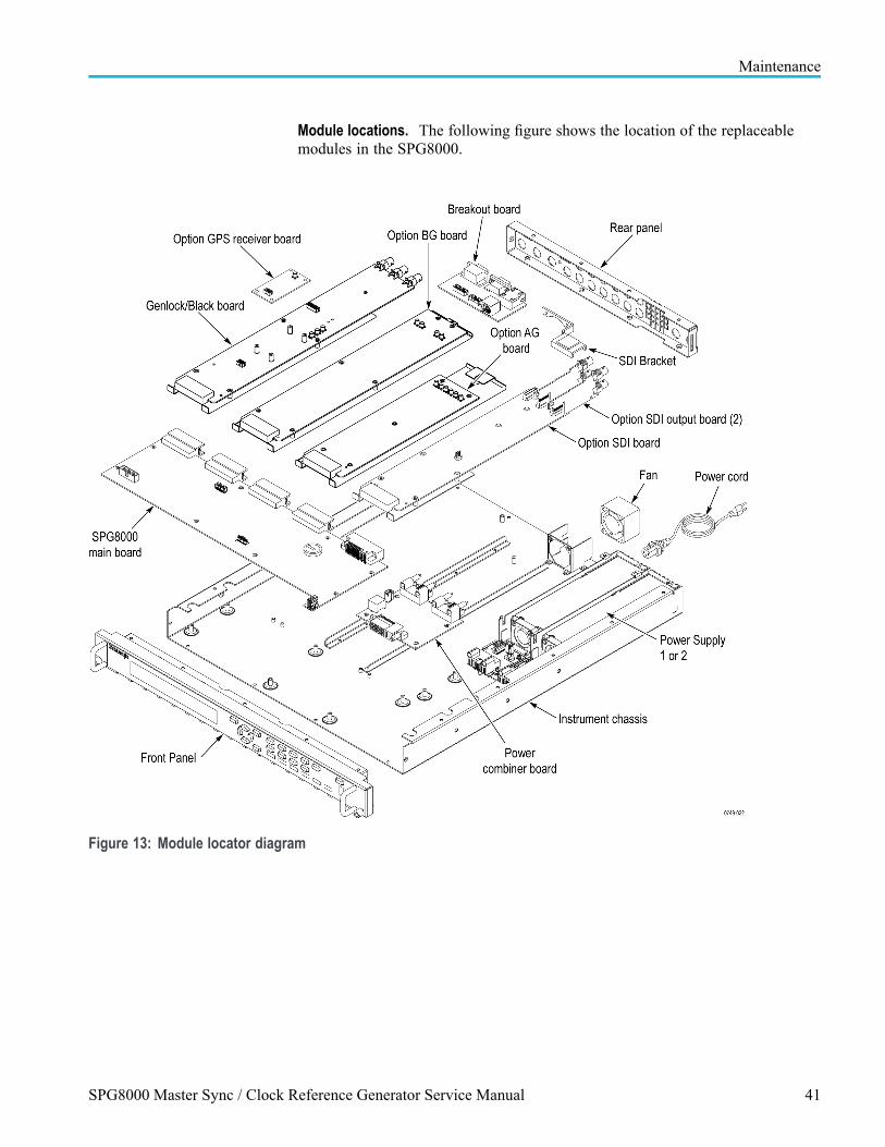
Maintenance
Module locations. The following figure shows the location of the replaceablemodules in the SPG8000.
Figure 13: Module locator diagram
SPG8000 Master Sync / Clock Reference Generator Service Manual 41

Maintenance
Interconnect illustrations The following illustrations and tables show where to reconnect cables.
Table 10: Cable connections table 1 of 3
Figure number Rear-panel connector Connects to
14- 1 SILENCE J440 on AG board
14-2 WORD CLK J9 on Genlock/Black board
14-3 AES 5 & 6 J420 on AG board
14-4 AES 7 & 8 J430 on AG board
14-5 AES 1 & 2 J400 on AG board
14-6 AES 3 & 4 J410 on AG board
14-7 CMPST 1 J930 on BG board
14-8 CMPST 2 J980 on BG board
14-9 BLACK 4 J830 on BG board
14-10 BLACK 5 J880 on BG board
14-11 REF J7 on Genlock/Black board
14-12 LOOP J3 on Genlock/Black board
Figure 14: Cable connections 1 of 3
42 SPG8000 Master Sync / Clock Reference Generator Service Manual

Maintenance
Table 11: Cable connections table 2 of 3
From To
Figurenumber Description
Figurenumber Description
15-1 Breakout board J1 16-2 Power combiner board JR101
15-2 Breakout board J2 16-4 Main board J703
15-3 Breakout board J3 16-4 Genlock/Black board J10
15-5 Light pipe header for the Antenna powerindicator
Rear-panel GPS ANT PWR rear-panel indicator
15-6 Option GPS Receiver board J1 Rear-panel GPS ANT rear-panel connector
15-7 Option GPS Receiver board J4 15-8 Genlock/Black board J12
Figure 15: Cable connections 2 of 3
SPG8000 Master Sync / Clock Reference Generator Service Manual 43
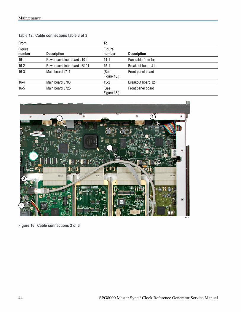
Maintenance
Table 12: Cable connections table 3 of 3
From To
Figurenumber Description
Figurenumber Description
16-1 Power combiner board J101 14-1 Fan cable from fan
16-2 Power combiner board JR101 15-1 Breakout board J1
16-3 Main board J711 (SeeFigure 18.)
Front panel board
16-4 Main board J703 15-2 Breakout board J2
16-5 Main board J725 (SeeFigure 18.)
Front panel board
Figure 16: Cable connections 3 of 3
44 SPG8000 Master Sync / Clock Reference Generator Service Manual

Maintenance
Locking line cord 1. You need no equipment to perform this removal procedure. Locate the linecord in the locator diagram. (See Figure 13.)
2. Set the SPG8000 so the instrument bottom is down on the work surface andthe rear is facing you.
3. Find the line cord on the rear panel. The locking cord has a release latch onthe top that must be pressed to remove the cord. Grasp the plug, press therelease latch, and pull the line cord and clamp away from the instrument.
4. To reinstall, insert the line cord into the power receptacle on the SPG8000rear panel until it latches into place.
SPG8000 Master Sync / Clock Reference Generator Service Manual 45

Maintenance
Top cover
CAUTION. When handling circuit boards, follow the ESD instructions. (Seepage 35, Electrostatic damage prevention.)
1. Set the SPG8000 so that the bottom is down on the work surface and therear is facing you.
2. Remove the top cover as follows:
a. Use a screwdriver with a #1 Phillips tip or #2 Phillips tip (depending onyour unit) to remove the 22 screws securing the top over to the instrument.
b. Lift the top cover off the chassis. (See Figure 17.)
3. To reinstall the top cover, reverse the steps. Torque all screws to 5.5 in/lbs.
Figure 17: Removing the top cover
46 SPG8000 Master Sync / Clock Reference Generator Service Manual

Maintenance
Rear panel The following steps identify which cables need to be disconnected and whichnuts, washers, and screws need to be removed before removing the rear panel.Some of the rear-panel connectors will remain installed in the rear panel.
1. Position the instrument so that the top cover is on the work surface and therear panel is facing you.
2. Use a screwdriver with a #1 or #2 Phillips tip to remove the four screwsattaching the rear panel to the chassis.
3. Turn the instrument over so the bottom is on the work surface.
4. Remove the top cover. (See page 46, Top cover.)
5. Disconnect the following:
Locate all of the cables that connect to the rear panel and disconnect all ofthese cables where they attach to the boards (the cables are permanentlyattached to the BNCs). Refer to Interconnect illustrations. (See page 42,Interconnect illustrations.)
Do not remove the light pipe from the rear-panel antenna power indicator.Instead, pull the light pipe from the header on the Genlock/Black generatorboard. When you remove the rear panel, the light pipe will come with it.When you reinstall the rear panel, reattach the light pipe to the header onthe Genlock/Black generator board.
Remove the jackscrews that hold the GPI and the GPI/LTC multi-pinconnectors to the rear panel.
Use a 9/16” socket to remove the nuts and lock-washers from the goldrear-panel connectors labeled: BLACK 1, BLACK 2, BLACK 3, SDI 1A,SDI 2A, SDI 1B, and SDI 2B. This will allow the rear-panel to slide offthe chassis. These BNCs will remain attached to the circuit boards, whilethe remaining BNCs will remain attached to the rear panel.
6. Pull the rear panel straight out from the chassis, carefully sliding the rear panelover the gold and multi-pin connectors that remain attached to the instrument.
7. To reinstall, reverse the procedure. Tighten the nuts on the BNCs to 14 in/lbs.Tighten the screws that attach the rear panel to the chassis, to 4 in/lbs.
SPG8000 Master Sync / Clock Reference Generator Service Manual 47

Maintenance
Main fan To remove and replace the chassis fan, follow these instructions:
1. Locate the chassis fan in the locator diagram. (See Figure 13 on page 41.)
2. Remove the instrument rear panel. (See page 47, Rear panel.)
3. Remove the two screws that attach the fan to the fan bracket and slide thefan out of the bracket.
4. To replace the fan, disconnect the cable from the Power Combiner boardand reverse the procedure.
Front panel assembly 1. Locate the Front Panel assembly in the locator diagram. (See Figure 13 onpage 41.)
2. Remove the top cover. (See page 46, Top cover.)
CAUTION. To prevent damage to the USB connector, use care when removing theFront Panel assembly. It is recommended that you remove the screws from thebottom of the instrument before you turn the instrument over to remove the sidescrews. This will prevent the Front Panel assembly from moving and damagingthe USB connector.
3. Remove the Front Panel assembly as follows: (See Figure 18.)
a. Set the instrument top down on the work surface with the front facing you.
b. Use a screwdriver with a #2 Phillips tip to remove the four screws securingthe Front Panel assembly to the bottom of the instrument chassis.
c. Turn the instrument bottom down on the work surface with the frontfacing you.
d. Use a screwdriver with a #2 Phillips tip to remove the two screws securingthe Front Panel assembly to the side of the chassis (one screw on eachside).
e. Disconnect the cables at J711 and J725 on the Main board.
f. Grasp the Front Panel assembly and carefully pull it forward over theUSB connector so that you do not damage the connector.
4. To reinstall the Front Panel assembly, perform steps 2 through 3 in reverseorder. Torque all screws to 5.5 in/lbs.
48 SPG8000 Master Sync / Clock Reference Generator Service Manual

Maintenance
Figure 18: Removing the front panel assembly
SPG8000 Master Sync / Clock Reference Generator Service Manual 49

Maintenance
Front panel subassemblies 1. Remove the Front Panel assembly. (See page 48, Front panel assembly.)
2. Set the Front Panel assembly so that you can access the screws on the backside of the assembly.
CAUTION. To prevent dirt from being trapped between the LCD display and thefront cover, keep the back of the Lexan cover clean while you are disassemblingthe Front Panel assembly.
3. Remove the front cover as follows. (See Figure 19.)
a. Use a screwdriver with a TORX T15 tip to remove the four screwssecuring the U-shaped handles to the front cover (two screws on eachside).
b. Use a screwdriver with a #2 Phillips tip to remove the four screws securingthe front cover to the front frame.
c. Grasp the front cover and pull it forward.
Figure 19: Disassembling the front panel assembly
50 SPG8000 Master Sync / Clock Reference Generator Service Manual
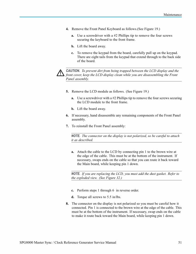
Maintenance
4. Remove the Front Panel Keyboard as follows.(See Figure 19.)
a. Use a screwdriver with a #2 Phillips tip to remove the four screwssecuring the keyboard to the front frame.
b. Lift the board away.
c. To remove the keypad from the board, carefully pull up on the keypad.There are eight tails from the keypad that extend through to the back sideof the board.
CAUTION. To prevent dirt from being trapped between the LCD display and thefront cover, keep the LCD display clean while you are disassembling the FrontPanel assembly.
5. Remove the LCD module as follows. (See Figure 19.)
a. Use a screwdriver with a #2 Phillips tip to remove the four screws securingthe LCD module to the front frame.
b. Lift the board away.
6. If necessary, hand disassemble any remaining components of the Front Panelassembly.
7. To reinstall the Front Panel assembly:
NOTE. The connector on the display is not polarized, so be careful to attachit as described.
a. Attach the cable to the LCD by connecting pin 1 to the brown wire atthe edge of the cable. This must be at the bottom of the instrument. Ifnecessary, swaps ends on the cable so that you can route it back towardthe Main board, while keeping pin 1 down.
NOTE. If you are replacing the LCD, you must add the dust gasket. Refer tothe exploded view. (See Figure 32.)
c. Perform steps 1 through 6 in reverse order.
d. Torque all screws to 5.5 in/lbs.
8. The connector on the display is not polarized so you must be careful how itconnected. Pin 1 is connected to the brown wire at the edge of the cable. Thismust be at the bottom of the instrument. If necessary, swap ends on the cableto make it route back toward the Main board, while keeping pin 1 down.
SPG8000 Master Sync / Clock Reference Generator Service Manual 51

Maintenance
Power supply There can be one or two power supplies installed in the SPG8000. If only oneis installed, it should be in slot one. The power module blank cover shouldbe installed in the other slot.
The power supply modules are replaced as a unit. There are no replaceablesubassemblies.
WARNING. Disconnect the power cord before removing the rear panel.
Disconnect the power cord when the power supply module is not installed. Highvoltage inside.
No tools are needed to remove the power supply. You do not need to remove theinstrument cover. The power supply module slides out the rear of the instrumentas a module. (See Figure 20.)
1. Disconnect the locking power cord.
2. Turn the power supply handle to the left.
3. Push the metal tab under the STATUS light to the left.
4. While holding that tab to the left, use the handle to pull the power supplymodule out of the instrument.
5. To replace the power supply, reverse the procedure.
52 SPG8000 Master Sync / Clock Reference Generator Service Manual

Maintenance
Figure 20: Removing the power supply
Power Combiner board The power combiner board combines the power from the two power supplies andprovides connections for the fan and Ethernet.
1. Remove all power supply modules from the instrument. (See page 52,Power supply.) The power supply modules will disconnect from the PowerCombiner board. (See Figure 21.)
2. Remove the instrument top cover. (See page 46, Top cover.)
3. Disconnect the two cables from the Power Combiner board.
4. Remove the four screws that attach the Power Combiner board to theinstrument chassis.
SPG8000 Master Sync / Clock Reference Generator Service Manual 53
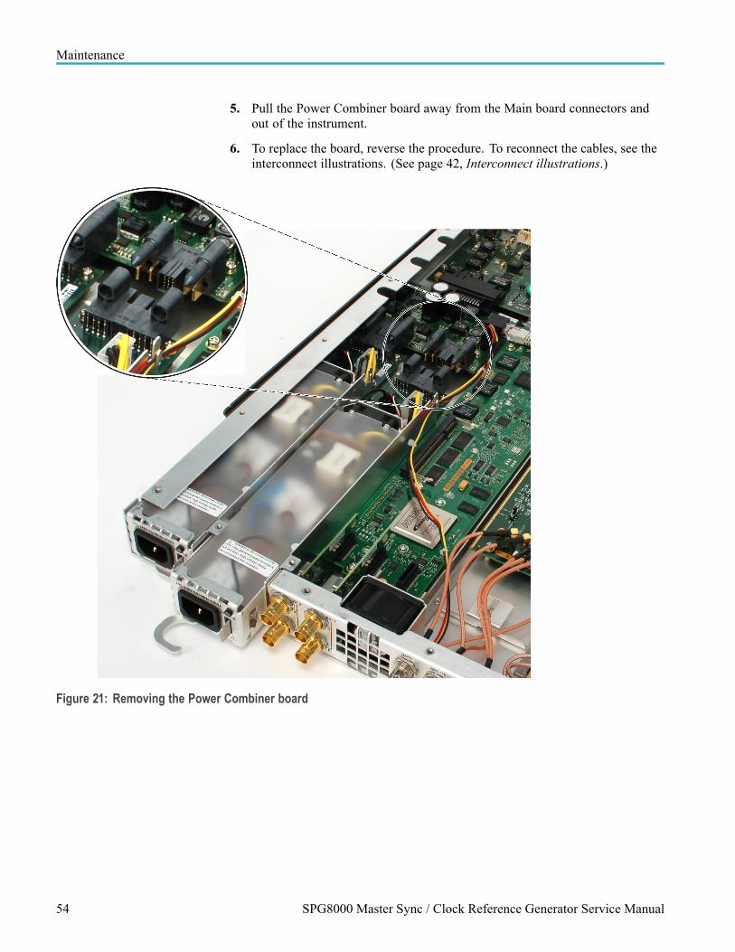
Maintenance
5. Pull the Power Combiner board away from the Main board connectors andout of the instrument.
6. To replace the board, reverse the procedure. To reconnect the cables, see theinterconnect illustrations. (See page 42, Interconnect illustrations.)
Figure 21: Removing the Power Combiner board
54 SPG8000 Master Sync / Clock Reference Generator Service Manual

Maintenance
Main board 1. Locate the Main board in the locator diagram. (See Figure 13.) Refer also tothe exploded view diagram for more details. (See Figure 31.)
2. Remove the Front Panel assembly. This is required because of the USBconnector on the Main board. (See page 48, Front panel assembly.)
3. Remove the Power Supply module(s). (See page 52, Power supply.)
4. Remove the Power Combiner board. (See page 53, Power Combiner board.)
5. Remove the rear panel. (See page 47, Rear panel.)
6. Remove the Genlock/Black generator assembly. (See page 59, Genlock/Blackboard and Option GPS board.)
7. Remove all installed option boards. (See page 57, Option AG board.) (Seepage 62, Option SDI board and Option SDI Output boards.)
8. Verify that all cables are disconnected from the Main board.
9. Set the instrument bottom down on the work surface with the right sidefacing you.
10. Remove the Main board as follows.
a. Use a screwdriver with a #2 Phillips tip to remove the eight screwssecuring the Main board to the chassis.
b. Lift the board up and away from the chassis.
11. To replace the Main board, perform steps 2 through 10 in reverse order.Torque all screws to 5.5 in/lbs.
Breakout board To remove and replace the Breakout board, follow these instructions:
1. Remove the jackscrews from the DSUB connectors on the rear panel.
2. Disconnect the three cables from the Breakout board. (See page 42,Interconnect illustrations.)
3. Remove the board from the instrument. (See Figure 31.)
4. Reverse the steps to reinstall the Breakout board. To connect the cables, seethe interconnect illustrations. (See page 42, Interconnect illustrations.)
SPG8000 Master Sync / Clock Reference Generator Service Manual 55

Maintenance
Option BG board You can remove and replace the Option BG board, the mounting plate under theboard, and the associated rear-panel connectors.
To remove the Option BG board.
1. Remove the rear panel. (See page 47, Rear panel.)
2. The circuit board is installed on top of a metal mounting plate, or “sled.” Donot remove the screws that attach the board to the plate at this time. Thereis one screw near the rear of the mounting plate that attaches the it to theSPG8000 chassis. Remove only that one screw.
3. Verify that all necessary cables are disconnected and that you have a clear pathto slide the board and mounting plate assembly from the rear of the instrument.
CAUTION. Circuit boards are sensitive to pressure. When disconnecting the optionboards from the Main board, be careful not to exert pressure on any circuit board.
5. Loosen the Option BG circuit board from the Main board. Pull the optionboard straight out the rear of the chassis and place it on a static-free surface.
To replace the Option BG board.
1. Make sure that your replacement board is installed on the mounting plate.
2. Starting with the rear panel removed, slide the replacement assembly into aposition that is close to where it will connect to the Main board. See theModule locator diagram. (See Figure 13.)
3. Line up the connector on the replacement assembly with the correspondingconnector on the Main board. Make sure that the pins line up and are notoffset.
4. Mate the connectors on the Main board with the new board connectors by“pinching” them together.
5. Install the screw that attaches replacement assembly (near the rear of themounting plate) to the instrument chassis.
6. Replace the instrument rear panel and all nuts and locking washers that wereremoved from the rear panel.
7. Connect all cables that were disconnected during the removal.
56 SPG8000 Master Sync / Clock Reference Generator Service Manual

Maintenance
To remove an Option BG rear-panel connector.
All of the rear-panel connectors associated with the Option BG are replaceable.These connectors are labeled: BLACK 4, BLACK 5, CMPST1, and CMPST2. Toreplace one of these connectors, follow these steps:
1. Use the 9/16” nut driver to remove the nut securing the damaged connector tothe rear panel. Remove the lock washer.
2. On the inside of the chassis, follow the cable that is attached to the BNC youare removing. Disconnect that cable from the circuit board jumper. Refer tothe Interconnect illustrations. (See page 42, Interconnect illustrations.)
3. Push the BNC inward and remove the cable assembly.
4. Replace the BNC/cable assembly by reversing the steps.
5. Tighten the BNC connector to 14 in/lbs.
To remove the Option BG mounting plate. To remove the mounting plate, followthe procedure for removing a mounting plate. (See page 66,Mounting plate.)
Option AG board You can remove and replace the Option AG board, the mounting plate under theboard, and the associated rear-panel connectors.
To remove the Option AG board.
1. Remove the top cover. (See page 46, Top cover.)
2. The circuit board is installed on top of a metal mounting plate, or “sled.” Donot remove the screws that attach the board to the plate at this time. Thereis one screw near the rear of the mounting plate that attaches the it to theSPG8000 chassis. Remove only that one screw.
3. Verify that all necessary cables are disconnected and that you have a clearpath to slide the board and mounting plate assembly out of the instrument.
CAUTION. Circuit boards are sensitive to pressure. When disconnecting the optionboards from the Main board, be careful not to exert pressure on any circuit board.
5. Loosen the Option AG circuit board from the Main board. Pull the optionboard out of the instrument and place it on a static-free surface.
SPG8000 Master Sync / Clock Reference Generator Service Manual 57

Maintenance
To replace the Option AG board.
1. Make sure that your replacement board is installed on the mounting plate.
2. Place the replacement assembly into a position that is close to where it willconnect to the Main board. See the Module locator diagram. (See Figure 13.)
3. Line up the connector on the replacement assembly with the correspondingconnector on the Main board. Make sure that the pins line up and are notoffset.
4. Mate the connectors on the Main board with the new board connectors by“pinching” them together.
5. Install the screw that attaches replacement assembly (near the rear of themounting plate) to the instrument chassis.
6. Replace the instrument rear panel and all nuts and locking washers that wereremoved from the rear panel.
7. Connect all cables that were disconnected during the removal.
To remove an Option AG rear-panel connector.
All of the rear-panel connectors associated with the Option AG are replaceable.These connectors are labeled: AES1+2, AES 3+4, AES 5+6, AES 7+8, Silence.To replace one of these connectors, follow these steps:
1. Use the 9/16” nut driver to remove the nut securing the damaged connector tothe rear panel. Remove the lock washer.
2. On the inside of the chassis, follow the cable that is attached to the BNC youare removing. Disconnect that cable from the circuit board jumper. Refer toInterconnect illustrations. (See page 42, Interconnect illustrations.)
3. Push the BNC inward and remove the cable assembly.
4. Replace the BNC/cable assembly by reversing the steps.
5. Tighten the BNC connector to 14 in/lbs.
To remove the Option AG mounting plate. To remove the mounting plate, followthe procedure for removing a mounting plate. (See page 66,Mounting plate.)
58 SPG8000 Master Sync / Clock Reference Generator Service Manual

Maintenance
Genlock/Black board andOption GPS board
You can replace the Genlock/Black board, the Option GPS Receiver board, theGPS ANT rear-panel connector, the light pipe connector, and the Genlock/Blackboard mounting plate. The high-speed BLACK 1, BLACK 2, and BLACK 3connectors are not replaceable.
NOTE. If the genlock/black board is replaced, the system must be locked up toGPS or GLONASS at least 15 minutes to initialize some variables such as the leapseconds. If you do not have option GPS installed, you must at least temporarilyinstall Option GPS, and allow the instrument to capture the leap seconds.
To remove the Genlock/Black board.
1. Remove the rear panel. (See page 47, Rear panel.)
2. The Genlock/Black board is installed on top of a metal mounting plate, or“sled.” Do not remove the screws that attach the board to the plate at thistime. (See Figure 35.)
3. Verify that all necessary cables are disconnected and that you have a clear pathto slide the board and mounting plate assembly from the rear of the instrument.
CAUTION. Circuit boards are sensitive to pressure. When disconnecting the optionboards from the Main board, be careful not to exert pressure on the Main board.
5. Loosen the Genlock/Black circuit board from the Main board. Pull theGenlock/Black board straight out the rear of the chassis and place it on astatic-free surface.
To replace the Genlock/Black board.
1. If you have Option GPS, make sure that the Option GPS Receiver boardis installed on your replacement Genlock/Black board. Verify that yourreplacement Genlock/Black board is installed on the mounting plate and thatall screws attaching the board to the plate are installed. Verify that the lightpipe header is installed on the board. This must be pressed in before the boardis mounted on the sled.
2. Starting with the rear panel removed, slide the replacement Genlock/Blackassembly into a position that is close to where it will connect to the Mainboard. See the Module locator diagram. (See Figure 13.)
3. Line up the connector on the replacement Genlock/Black assembly with thecorresponding connector on the Main board. Make sure that the pins lineup and are not offset.
4. Mate the connectors on the Main board with the replacement Genlock/Blackboard connectors by “pinching” them together.
SPG8000 Master Sync / Clock Reference Generator Service Manual 59

Maintenance
5. Replace the rear panel and all nuts and locking washers that were removedfrom the rear panel.
6. Connect all cables that were disconnected. Refer to Interconnect illustrations.(See page 42, Interconnect illustrations.)
To remove and replace the Option GPS Receiver board. To remove and replace theOption GPS Receiver board, follow these instructions.
1. Remove the instrument top cover. (See page 46, Top cover.)
2. Disconnect the cables from the two connectors on the board. (See page 42,Interconnect illustrations.)
3. Use the torque driver (T10 tip) to remove the four screws connecting thereceiver board to the Genlock/Black board and remove the Receiver board.
4. Reverse the procedure to replace the board. Tighten the screws to 8 in/lbs.
To remove and replace the rear-panel GPS ANT connector. To replace the GPSANT connector, you will need to replace the BNC and the attached cable. Proceedas follows:
1. Remove the Breakout board. (See page 55, Breakout board.)
2. Remove the nut securing the damaged connector to the rear panel. Removethe lock washer.
3. On the inside of the chassis, follow the cable that is attached to the GPS ANTconnector. Disconnect that cable from the circuit board. Refer to Interconnectillustrations. (See page 42, Interconnect illustrations.)
4. Push the BNC inward and remove the cable assembly.
5. Replace the BNC/cable assembly by reversing the steps.
6. Tighten the BNC connector to 14 in/lbs.
60 SPG8000 Master Sync / Clock Reference Generator Service Manual

Maintenance
To remove and replace the light-pipe connector. To replace the light-pipe boardconnector, proceed as follows:
CAUTION. Do not remove the light pipe board connector from the board unlessyou have a replacement board connector available. Removing the light pipe boardconnector damages it, so it cannot be reused.
1. Pull the light pipe out of the board connector. This is a slip-fit and shouldcome apart easily.
2. Remove the instrument rear panel. (See page 47, Rear panel.)
3. Move the instrument rear panel away from the chassis, pulling the lightpipe out with it.
4. Pull the light pipe out of the light pipe lens in the external rear panel. This is aslip-fit and should come apart easily.
5. Gently remove the light pipe lens from the instrument rear panel.
6. When reassembling, follow this sequence:
a. Insert the light pipe into the new light pipe lens.
b. Thread the light pipe through the instrument rear panel until the lens isagainst the rear panel.
c. Gently push the light pipe lens into place in the rear panel.
d. Replace the instrument rear panel.
e. Plug the light pipe into the light pipe board connector.
To remove and replace the Genlock/Black board mounting plate. To remove themounting plate, follow the procedure for removing a mounting plate. (Seepage 66, Mounting plate.)
SPG8000 Master Sync / Clock Reference Generator Service Manual 61

Maintenance
Option SDI board andOption SDI Output boards
You can remove and replace the Option SDI board, the two Option SDI Outputboards, and the Option SDI board mounting plate. The four gold rear-panel BNCsattached to the Option SDI board are not replaceable.
To remove and replace the bracket securing the SDI output boards.
WARNING. Attaching and removing cables from the SDI Output boards can loosenthem from the SDI board connectors. This can cause the pins between the outputboards and SDI board connectors to not be fully engaged. The bracket attached tothe chassis fan keeps the output boards connections secure.
1. Remove the instrument top cover. (See page 46, Top cover.)
2. Remove the two nuts securing the bracket to the chassis fan screws using a7/32 inch nut driver.
Figure 22: Remove the two nuts
3. Pull the bracket from the two extended screws on the chassis fan and removeit from the instrument.
62 SPG8000 Master Sync / Clock Reference Generator Service Manual
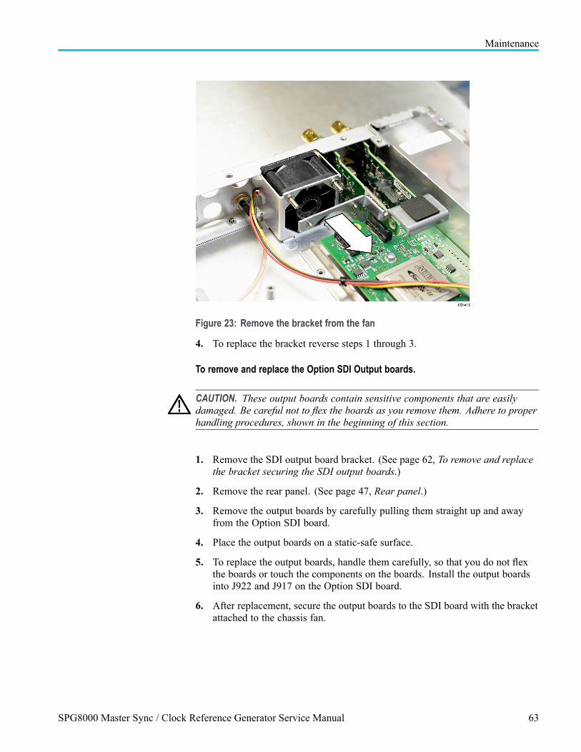
Maintenance
Figure 23: Remove the bracket from the fan
4. To replace the bracket reverse steps 1 through 3.
To remove and replace the Option SDI Output boards.
CAUTION. These output boards contain sensitive components that are easilydamaged. Be careful not to flex the boards as you remove them. Adhere to properhandling procedures, shown in the beginning of this section.
1. Remove the SDI output board bracket. (See page 62, To remove and replacethe bracket securing the SDI output boards.)
2. Remove the rear panel. (See page 47, Rear panel.)
3. Remove the output boards by carefully pulling them straight up and awayfrom the Option SDI board.
4. Place the output boards on a static-safe surface.
5. To replace the output boards, handle them carefully, so that you do not flexthe boards or touch the components on the boards. Install the output boardsinto J922 and J917 on the Option SDI board.
6. After replacement, secure the output boards to the SDI board with the bracketattached to the chassis fan.
SPG8000 Master Sync / Clock Reference Generator Service Manual 63

Maintenance
To remove the Option SDI board.
1. Remove the SDI output board bracket. (See page 62, To remove and replacethe bracket securing the SDI output boards.)
2. Remove the rear panel and the Option SDI Output Boards. (See page 63, Toremove and replace the Option SDI Output boards.)
3. The Option SDI board is installed on a metal mounting plate, or “sled.” Donot remove the screws that attach the board to the mounting plate at this time.One screw near the rear of the chassis attaches the mounting plate to thechassis. Remove only that one screw.
4. Verify that all necessary cables are disconnected and that you have a clear pathto slide the board and mounting plate assembly from the rear of the instrument.
CAUTION. Circuit boards are sensitive to pressure. When disconnecting the optionboards from the Main board, be careful not to exert pressure on the Main board.
6. Loosen the Option SDI circuit board from the Main board. Pull the optionboard straight out the rear of the chassis and place it on a static-free surface.
64 SPG8000 Master Sync / Clock Reference Generator Service Manual

Maintenance
To remove and replace the mounting plate or heat sink. Follow this procedure toremove and replace a heat sink or mounting plate for the Option SDI.
NOTE. You can reuse a removed heat sink, but you must use a new gap pad.
1. Remove the Option SDI board and sled from the instrument. (See page 62,Option SDI board and Option SDI Output boards.)
2. Remove the three screws attaching the heat sink to the mounting plate.
3. Remove the 7 screws that attach the SDI board to the mounting plate andheat sink (2 screws are next to the FPGA) and remove the board. Placethe removed circuit board assembly on a static-free surface. Follow properhandling instructions for a circuit board. Instructions are provided at thebeginning of this remove and replace section.
4. Turn the SDI board upside down and gently remove the heat sink. Be carefulnot to flex the circuit board. Clean any remaining parts of the old gap pad offthe circuit board using alcohol. Allow the board to dry.
5. Install the new heat sink to the sled using the three screws.
6. Peel the protective film from one side of new the gap pad and install it ontop of the heat sink.
7. Remove the film from the other side of the new gap pad.
8. Position the Option SDI board over the heat sink and gap pad, aligning theholes in the circuit board (on each side of the FPGA) with the threaded postsof the heat sink. Use care not to damage the gap pad.
9. Loosely install the two T10 TORX screws with English threads through thecircuit board and into the heat sink. Do not tighten.
10. Loosely install the 5 additional screws (Phillips head metric) that attach thecircuit board to the mounting plate.
11. Tighten all 7 screws attaching the Option SDI board to the mounting plateand torque to 5.5 in/lb.
SPG8000 Master Sync / Clock Reference Generator Service Manual 65

Maintenance
To replace the Option SDI board.
1. Verify that the Option SDI board is installed on the metal mounting plate.
2. Starting with the rear panel removed, slide the replacement Option SDIassembly into a position that is close to where it will connect to the Mainboard, as shown in the module locator diagram. (See Figure 13.)
3. Line up the connector on the replacement Option SDI board with thecorresponding connector on the Main board. Make sure that the pins lineup and are not offset.
4. Mate the connectors on the Main board with the replacement board connectorsby “pinching” them together.
5. Install the two SDI Output boards in connectors J922 and J917 on theOption SDI board.
6. Reinstall the rear panel and all of the nuts and lock washers that were removedfrom the rear panel.
7. Install the screw that attaches the Option SDI assembly (near the rear of themounting plate) to the chassis.
8. Reinstall the bracket that secures the SDI output boards by reversing theremove procedure for the bracket. (See page 62.)
9. Connect all cables that were disconnected. Refer to Interconnect illustrations.(See page 42, Interconnect illustrations.)
10. Replace the instrument top cover.
Mounting plate The Genlock/Black, Option BG, and Option AG are mounted on a metal mountingplate or “sled”. This piece protects the circuit board from being flexed duringinstallation or removal. If you need to replace this mounting plate, follow theseinstructions:
1. Remove the circuit board assembly from the instrument. See the remove andreplace instructions for that board. (See page 59, Genlock/Black board andOption GPS board.) (See page 57, Option AG board.) (See page 56, OptionBG board.)
2. Remove the screws that attach the circuit board to the mounting plate.(Genlock/Black board 4 screws, Option BG board 6 screws, Option AGboard 5 screws).
3. Carefully remove the circuit board from the mounting plate and place thecircuit board on a static-safe surface. Do not flex the circuit board.
4. To replace the mounting plate, reverse the procedure. Tighten the screwsto 5.5 in/lbs.
66 SPG8000 Master Sync / Clock Reference Generator Service Manual
Maintenance
TroubleshootingThis section contains information about how to troubleshoot instrument problemsin order to isolate faulty modules in the SPG8000.
Diagnostics andperformance checks
When troubleshooting an unknown instrument problem, perform the performanceverification procedures for the SPG8000 and installed options. If the problem isknown, run only the diagnostic portion of the performance verification proceduresto gain information about the subsystems. (See the SPG8000 Specifications andPerformance Verification Technical Reference manual.)
Included in the performance verification procedures are instructions for runningand viewing the SPG8000 internal diagnostics. The diagnostics include thefollowing:
Readouts of tests including power-on diagnostics, clock frequencies,temperatures, Main board and slot voltages, and fan speed
Read/write tests for the signal memory of Option BG.
Diagnostics for Genlock/Black, Option GPS, and Option SDI
Slot diagnostics to test the power supply and signal connections on the Mainboard I/O slot connectors.
If the message Fail: "a module name" Diag error is displayed, replace themodule.
Event Log The Event Log records when some types of events occur. These events canbe normal or they may indicate an issue. The exact use of the event log fortroubleshooting will vary with the type of problem. The event log is especiallyuseful in finding intermittent problems or problems that can be correlated tooutside events by the log time stamps. See the SPG8000 Quick Start User Manualfor details on the types of events recorded in the Event Log.
SPG8000 Master Sync / Clock Reference Generator Service Manual 67

Maintenance
Back up your instrumentsettings
CAUTION. After you execute the diagnostics, you will need to cycle power onthe instrument. If you have not saved the instrument settings, be sure to savethe current instrument settings to a preset, and then recall the settings after thediagnostic tests are completed.
1. Press the SYSTEM button.
2. Press the up () or down () arrow button to select PRESET.
3. Press the ENTER button.
4. Press the up () or down () arrow button to select SAVE.
5. Press the left () or right () arrow button to select the preset number towhich you will save the instrument settings.
6. Press the ENTER button.
To power up in factorymode
Putting the instrument into factory mode allows access to calibration, and itallows the module to show in the menus even if it fails the POST routine. Whenyou perform a procedure that requires you to you restart the instrument in factorymode, proceed as follows:
1. Press and hold the STATUS, ENTER, and Front Panel ENABLE buttonssimultaneously.
2. Continue holding the buttons until the message SPG8000 Booting... displays.
3. When the message SPG8000 Booting... displays, while continuing to holdthe Front Panel ENABLE button, release the STATUS and ENTER buttons.
4. When the message SPG8000 Start up with Factory Mode displays, releasethe Front Panel ENABLE button.
68 SPG8000 Master Sync / Clock Reference Generator Service Manual

Maintenance
Oscillator calibration The diagnostic readouts in the SYSTEM : DIAGNOSTICS menu includereadouts for Tune and Cal, which are related to the oscillator calibration asdescribed below:
TUNE The Tune readout indicates how far the system is being pulled from thecalibrated internal frequency value in order to lock to an external reference. Ifyou use Option GPS or an AGL7 module installed in a TG8000 generator tolock to a video source that is 5 parts per million high, the tune will say +5e-6.This allows you to measure the frequency of the reference input and to seeif the input is near the end of the available tuning range. If the system is ininternal mode, the tune value should be 0.00 e-6 and the integer values willequal the calibration value.
The integer values indicate the actual tuning control word. The allowed rangeof this tuning word is 0 to 4,194,304. The first number is the actual value atthe present time, and the second value is the target value for the control loop.In most cases, these two values are the same. However, when the systemmust make a large frequency change (depending on instrument mode), thevalue may slew slowly to the target value to stay inside the allowed slew ratefor reference systems. In this case, the first value will slew over seconds orminutes until it equals the second value. If the instrument is taking a longtime to lock, this display may provide valuable information about what ishappening.
The Tune diagnostic readout allows you to see if the instrument must becalibrated. If the instrument is locked to a traceable reference, any tune valueindicates error in the instrument calibration. For example, if the instrument islocked to GPS or GLONASS and the Tune is more that 0.1 e-6, you shouldconsider calibrating the internal frequency of the instrument. This can bedone in service with no disruption to the operation. See the Oven oscillatorcalibration procedure in the SPG8000 Quick Start Manual for instructions.
CALIBRATION This readout represents the correction applied to the ovenoscillator clock to calibrate the frequency when in internal mode. The integervalue is the tuning control word to make this happen. An example readout is“0.59e-6”. This is the fractional correction being applied, which in this casethis is 0.59 parts in 1 million. When the instrument calibration is performed,this number will typically change.
Over the life of the oven, the expected drift is +-2.5 e -6, so this number shouldalways be in this range. If the number is not in this range, the instrument mayhave been miscalibrated or the oven may have drifted out of specification. Seethe Oven oscillator calibration procedure in the SPG8000 Quick Start Manualfor instructions.
SPG8000 Master Sync / Clock Reference Generator Service Manual 69

Maintenance
Slot I/O Test The Slot I/O test runs diagnostics on the busses between the main instrumentand the generator modules. This test provides a message that tells whether theslot passed, and if not, provides an error code. The error codes and meaningsare shown in the table. (See Table 13.)
To run the slot I/O test.
1. Power up the instrument in factory mode. (See page 105, To power up infactory mode.)
2. Press the SYSTEM button.
3. Use the up () or down () arrow button to select DIAGNOSTICS.
4. Press ENTER.
5. Use the up () or down () arrow button to select SLOT I/O.
6. Press ENTER to run.
7. Check to see whether the slot passed the test, or whether there is an errormessage to help you troubleshoot the problem.
Table 13: Slot I/O test error codes
Error code Description
1 Data Bus Test 1
1A Data Bus Test 2
2 Data Bus Test 3
3 Data Bus Test 4
4 Data Bus Test 5
5 Data Bus Test 6
6 Address Bus Test 1
7 Address Bus Test 2
8 Address Bus Test 3
9 MCLK Test
A ACLK Test
B 54 MHz CLK test
C 74.176 MHz CLK test
BC Frame 0 / 54 and 74.176 MHz clock test
D 54 MHz CLK test
E 74.25 MHz CLK test
DE Frame 1 / 54 and 74.25 MHz clock test
F Frame 2 / 54 MHz test
10 Genlock Frame test
11 +5 V test
70 SPG8000 Master Sync / Clock Reference Generator Service Manual

Maintenance
Table 13: Slot I/O test error codes (cont.)
Error code Description
12 +8 V test
13 –5 V and +3.3 V test
14 IRQ signal test
99 Incorrect Hardware configuration
SPG8000 diagnostics The following table lists the diagnostics that are available in the SPG8000. (SeeTable 14.) The diagnostic type is accessed using the up and down arrow buttons(/). The tests are accessed using the left and right arrow buttons ( /). Tocheck the results of a diagnostic test, proceed as follows:
1. Enter the factory mode. (See page 105, To power up in factory mode.)
2. Press the SYSTEM button.
3. Use the up () or down () arrow button to select DIAGNOSTICS.
4. Press ENTER.
5. Use the up, down, right, and left arrow buttons to navigate through all of thediagnostic reports, as shown in the following table. (See Table 14.)
6. Check that the tests report (OK) unless otherwise specified in the followingtable. If a warning is given, take corrective action until the test reports (OK).
Table 14: SPG8000 system diagnostics
SYSTEM: DIAGNOSTICS:
TUNE: (/ )
Tune: ( / ) “Tune” indicates how much the Genlock, GPS or GLONASS reference is pulling the box from theCal value. If not externally referenced, this will be zero.
Phase: ( / ) "Phase" is for GPS lock mode only, shows the phase measurements and the synthesizer correction value.
CALIBRATION: (/ )
Cal: This test indicates the correction applied to the oven to calibrate the clocks.
PLL STATUS MAIN: (/ )
12.288Lk 54:Lk 74.25Lk 74.176Lk
This test checks the lock status of the four secondary audio and video clocks. All should read “Lk” to indicate locked.
PLL STATUS SDI: ( / )
Flex0: Lock Flex1: Lock
This tests the Flexible Clock Generators on the SDI board. “Unlock” indicates an error.
DDS STATUS SDI: ( / )
DDS0 Phase: Lock DDS1 Phase: Lock
This tests that each DDS in the SDI flexible clock generator is phased up to the selected incoming frame.
“Unlock” indicates an error.
SPG8000 Master Sync / Clock Reference Generator Service Manual 71
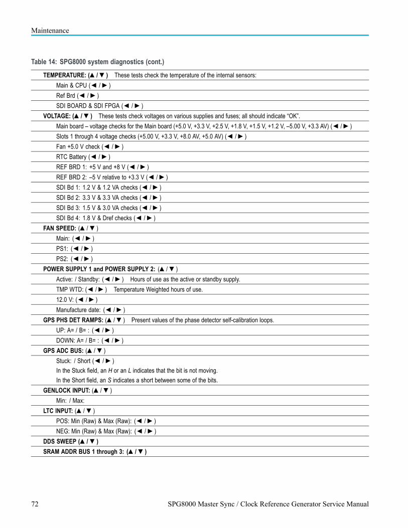
Maintenance
Table 14: SPG8000 system diagnostics (cont.)
TEMPERATURE: (/ ) These tests check the temperature of the internal sensors:
Main & CPU ( / )
Ref Brd ( / )
SDI BOARD & SDI FPGA ( / )
VOLTAGE: (/ ) These tests check voltages on various supplies and fuses; all should indicate “OK”.
Main board – voltage checks for the Main board (+5.0 V, +3.3 V, +2.5 V, +1.8 V, +1.5 V, +1.2 V, –5.00 V, +3.3 AV) ( / )
Slots 1 through 4 voltage checks (+5.00 V, +3.3 V, +8.0 AV, +5.0 AV) ( / )
Fan +5.0 V check ( / )
RTC Battery ( / )
REF BRD 1: +5 V and +8 V ( / )
REF BRD 2: –5 V relative to +3.3 V ( / )
SDI Bd 1: 1.2 V & 1.2 VA checks ( / )
SDI Bd 2: 3.3 V & 3.3 VA checks ( / )
SDI Bd 3: 1.5 V & 3.0 VA checks ( / )
SDI Bd 4: 1.8 V & Dref checks ( / )
FAN SPEED: (/ )
Main: ( / )
PS1: ( / )
PS2: ( / )
POWER SUPPLY 1 and POWER SUPPLY 2: (/ )
Active: / Standby: ( / ) Hours of use as the active or standby supply.
TMP WTD: ( / ) Temperature Weighted hours of use.
12.0 V: ( / )
Manufacture date: ( / )
GPS PHS DET RAMPS: (/ ) Present values of the phase detector self-calibration loops.
UP: A= / B= : ( / )
DOWN: A= / B= : ( / )
GPS ADC BUS: (/ )
Stuck: / Short ( / )
In the Stuck field, an H or an L indicates that the bit is not moving.
In the Short field, an S indicates a short between some of the bits.
GENLOCK INPUT: (/ )
Min: / Max:
LTC INPUT: (/ )
POS: Min (Raw) & Max (Raw): ( / )
NEG: Min (Raw) & Max (Raw): ( / )
DDS SWEEP (/ )
SRAM ADDR BUS 1 through 3: (/ )
72 SPG8000 Master Sync / Clock Reference Generator Service Manual

Maintenance
Table 14: SPG8000 system diagnostics (cont.)
SRAM DATA bus 1 through 3: (/ )
SRAM MEM TEST: (/ )
DDR2 ADDRESS BUS 1 and BUS 2: (/ )
DDR2 MEM TEST: (/ )
RUN: (/ ) Pressing ENTER runs the module memory tests.
MANUAL TUNE: (/ ) Press ( / ) buttons to tune the synthesizer outputs.
GPS IO TEST: (/ ) Press ENTER to run the Slot I/O test.
SPG8000 troubleshooting The following table lists some common problems and tells how to troubleshootthem.
Table 15: SPG8000 troubleshooting procedures
Problem Troubleshooting steps
No power or lights Check the main power supply as follows:
1. Remove instrument top cover.
2. Apply AC power.
3. Use a voltmeter to check the voltage on TP21 / Fuse F1. TP21 is unlabeled; it is located justto the left of Fuse F1. (See Figure 24 on page 74.)
5. If power is present on TP21, check fuses F1 and F2. Replace fuses if necessary.
4. If 5 V is not present, check the Power Combiner board, then the power supply module(s).
6. If there still no power, replace the Main board.
Fault LED illuminated All of the conditions that drive the fault light should be displayed in the mainframe diagnosticscreen. To view the diagnostics, refer to SPG8000 System Diagnostics. (See page 71,SPG8000 diagnostics.)
Any of the fans not working Run diagnostics and check the fan speeds. The main fan is near the rear panel. The PS1 fanis in the first supply, and the PS2 fan is in power supply 2.
If one of the three fans is not working, check the voltage on the three fans with a voltmeter.The voltage should be in the 8 V to 12 V range. If the voltage is not within that range, replacethe Power Combiner board. If the voltage is within the range, replace the fan.
Instrument not able to genlock Adjust/check the master clock. (See page 13, Adjust master clock using a frequency signalgenerator.) After adjustment, go into the diagnostics and verify that the CAL value readout isless than ±2.5e–6. If it is not, replace the oven or the Main board.
In Factory mode, run the PLL Range Check from the diagnostics (perform the commondiagnostic tests in the SPG8000 Specifications and Performance Verification TechnicalReference manual). Verify that all the secondary clocks can tune at least ±90e -6. If theycannot, replace the Main board.
Display problems On power up, the LCD display should initially be dark except for a visible set of black squareson the top row. After a second or two, the LCD backlight should come on and a bootingmessage should appear. If the backlight does not come on, check fuse F700 on the Mainboard, and then replace the display. If the text is not there, replace the display, then thecable, and finally the Main board, if necessary.
SPG8000 Master Sync / Clock Reference Generator Service Manual 73

Maintenance
Table 15: SPG8000 troubleshooting procedures (cont.)
Problem Troubleshooting steps
Keyboard/front panel problems On power up, the front panel buttons and indicators should light up in groups of 3 to 5. Thissequence will repeat about 4 times while waiting for the instrument to boot. The flashingsequence is controlled by the front panel, only power is required from the Main board. So if theflashing does not occur, replace the front panel.
An unprogrammed new front panel will not flash until the instrument software has fully bootedand loaded the code into the front panel. After the system has booted, run the keyboarddiagnostics as follows:
1. Restart the instrument in Factory mode. (See page 105, To power up in factory mode.)
2. Press the SYSTEM button.
3. Use the up arrow () to get to DIAGNOSTICS.
4. Press ENTER.
5. Use the up arrow () to select DIAGNOSTICS : RUN.
6. Use the right arrow () to select FRONT PANEL KEY test.
7. Press ENTER.
8. Follow the instructions on the display to run the keyboard diagnostics.
If there is an error, replace the keyboard. If that does not fix the problem, replace the cable. Ifthat does not fix the problem, replace the Main board.
Remote interface problems Use the GPI submenu under the SYSTEM menu to verify that the GPI alarm output is enabledand that the desired error conditions are also enabled
Module(s) not working properly Refer to the troubleshooting procedure in this section for the module in question.
Figure 24: Main board (view from top)
74 SPG8000 Master Sync / Clock Reference Generator Service Manual

Maintenance
Option AG troubleshooting This section contains instructions and procedures for troubleshooting theOption AG. These procedures will help you decide whether it is necessary toreplace your module.
If the SPG8000 does not boot up or if the display is not working, go to thebeginning of the troubleshooting section. (See page 67, Troubleshooting.)
Required equipment. The equipment listed in the following table is required fortroubleshooting.
Table 16: Equipment required to troubleshoot the Option AG
Equipment description Minimum requirements/example
Screwdriver handle Accept Phillips-driver bits
#1 Phillips tip Phillips-driver bit for #1 size screw heads
Procedure.
1. Before you start to troubleshoot a problem, back up your instrument settingsto a preset. (See page 68, Back up your instrument settings.)
2. Check the diagnostics in the SPG8000 troubleshooting table. (See Table 15.)The diagnostics check many of the signals that the Main board provides tothe AG board.
3. Run the slot I/O test on the Genlock/Black board. This tests many of thesignals needed by the AG board.
4. Use the troubleshooting diagram to troubleshoot Option AG. (See Figure 25.)
5. After the problem is solved, recall the preset you created.
SPG8000 Master Sync / Clock Reference Generator Service Manual 75

Maintenance
Figure 25: Option AG troubleshooting procedure
76 SPG8000 Master Sync / Clock Reference Generator Service Manual

Maintenance
Option BG troubleshooting This section contains instructions and procedures for troubleshooting the OptionBG. These procedures will help you decide whether it is necessary to replaceyour Option BG module.
If the SPG8000 does not boot up or if the display is not working, go to thebeginning of the troubleshooting section. (See page 67, Troubleshooting.)
Required equipment.
The equipment listed in the following table is required for troubleshooting.
Table 17: Equipment required for Option BG troubleshooting
Equipment description Minimum requirements/example
Screwdriver handle Accept Phillips-driver bits
#1 Phillips tip Phillips-driver bit for #1 size screw heads
Procedure.
1. Before you start to troubleshoot a problem, back up your instrument settingsto a preset. (See page 68, Back up your instrument settings.)
2. Check the diagnostics in the SPG8000 troubleshooting table. (See Table 15.)The diagnostics check many of the signals that the Main board provides tothe BG board.
3. Run the slot I/O test on the Genlock/Black board. This tests many of thesignals needed by the BG board.
4. Use the Option BG troubleshooting diagram to troubleshoot the option. (SeeFigure 25.)
5. After the problem is solved, recall the preset that you created.
SPG8000 Master Sync / Clock Reference Generator Service Manual 77

Maintenance
Figure 26: Option BG troubleshooting procedure
78 SPG8000 Master Sync / Clock Reference Generator Service Manual

Maintenance
Genlock/Blacktroubleshooting
This section contains instructions and procedures for troubleshootingGenlock/Black board. These procedures help you decide whether it is necessaryto replace your module.
If the SPG8000 does not boot up or if the display is not working, go to thebeginning of the troubleshooting section. (See page 67, Troubleshooting.)
Required equipment. The equipment listed in the following table is needed totroubleshoot the Genlock/Black generator module.
Table 18: Equipment required for troubleshooting the Genlock/Black generator module
Equipment Requirement Suggested equipment
Option GPS If the DUT does not have an Option GPSinstalled, must have an Option GPS totemporarily install in the DUT
GPS or GLONASS Antenna signal source(2) 1
Good GPS or GLONASS signal requiredfor both the Option GPS under test andthe reference unit. If only one antennafeed is available, a signal splitter may beused
Digital Multimeter Used to check power supply voltages andfuses
Fluke 87 or equivalent
75 Ω BNC cables (4) Length: 42 inches, used to connect theinstruments
Tektronix part number 012-0074-00
ROHS compliant ESD safe solderingworkstation
Any soldering must be ROHS compliant
Frequency Counter (optional) Used for an alternate method to checkfrequency accuracy
Fluke PM6685 or equivalent
1 The reference unit must have the same type of GPS receiver as the DUT unit. (See page 8, How to determine which GPS receiver is installed in your instrument.)
Performance verification. If there is a problem, first perform the Base UnitFunctional Test, found in the SPG8000 Specifications and PerformanceVerification manual. Any problems found using that procedure can be a startingpoint for troubleshooting. Even if you do not perform the entire performanceverification procedure, at a minimum check the diagnostics. These give valuableinformation on the generator board and the mainframe signals that drive it.
SPG8000 Master Sync / Clock Reference Generator Service Manual 79

Maintenance
General problems. General problems and actions to follow are shown in thefollowing table. (See Table 19.)
Table 19: General problems – Genlock/Black board
Problem Actions
Fails Power On Self Test(POST)
GPS does not appear in menu
Run power on test procedure. (See page 91, Power on self test for Option GPS (POST).)
Check for current software. (See page 81, Check the installed firmware version.)
Run power supply test. (See page 83, Test power supply.)
Power up in factory mode and run the slot I/O test. (See page 70, Slot I/O Test.)
No Black Burst outputs
No LTC outputs
Run power supply test.
Verify configuration by setting to factory defaults. (See page 91, Set to factory defaults(Option GPS).)
Check diagnostics reported values. (See page 82, Check diagnostic reported values.)
Power up in factory mode and run the slot I/O test. (See page 70, Slot I/O Test.)
If no other problems found, replace the Genlock/Black board.
Unstable genlock or unable togenlock
Run Internal Mode Oven test. (See page 86, Test internal mode oven.)
Check that the reference select is set to the correct mode. See the SPG8000 User manualfor directions.
Verify reference signal is valid and is the correct format. Use a WFM7120 or WFM8300waveform monitor.
Check ADC Bus diagnostics. (See page 87, ADC bus diagnostics.)
Power up in factory mode and run the slot I/O test. (See page 70, Slot I/O Test.)
If no other problem found, replace Genlock/Black generator board.
Unable to detect or use timecode
Verify that the time code is present on the input signal. Use a WFM7120 or WFM8300waveform monitor.
Verify that the time source select is set to VITC. See the SPG8000 Technical Referencemanual for directions.
Verify that the time sync method is set as needed. The “Follow” mode is best fortroubleshooting purposes. SPG8000 Technical Reference manual for directions.
Check the STATUS menu for the Genlock input amplitude and VITC present indicators.See the SPG8000 Technical Reference manual for directions.
Power up in factory mode and run the slot I/O test. (See page 70, Slot I/O Test.)
Lock to GPS or GLONASS to set leap seconds. (See page 88, Lock to GPS to set leapseconds.)
If no other problem found, replace the Genlock/Black generator module.
80 SPG8000 Master Sync / Clock Reference Generator Service Manual

Maintenance
Power on self test (POST). When you first apply power to an SPG8000, theGenlock/Black generator board runs a Power On Self Test (POST). If an error isencountered during this POST, the display will show one of several error codes.Watch the display as the instrument powers on, and note any error codes. Checkthe table to see the meaning of the error codes. (See Table 20.)
Table 20: POST error codes for the Genlock/Black module
ErrorCode Meaning1: CPLD constant 1 check (0xAAAA or 0x00AA based on cpld version at addr 0x8)2: CPLD constant 2 check (0x5555 or 0x0055 based on cpld version at addr 0xA)3: CPLD R/W error (writes 0x5555 to addr 0x102 and confirms)4: CPLD R/W error (writes 0xAAAA to addr 0x102 and confirms)5: Error copying DO Fpga to Genlock/Black EEPROM7: Error copying BB Fpga to Genlock/Black EEPROM9: DO Fpga constant check (0x55 at addr 0x501000)10: DO Fpga R/W error (writes 0x5555 to addr 0x501024 and confirms)11: DO Fpga R/W error (writes 0xAAAA to addr 0x501024 and confirms)12: BB Fpga R/W error (writes 0x5555 to addr 0x400008 and confirms)13: BB Fpga R/W error (writes 0xAAAA to addr 0x400008 and confirms)255: Not an error. This code may appear following some firmware updates.
Check the installed firmware version.
1. Press the SYSTEM button.
2. Press the up () or down () arrow buttons to select VERSION INFO(F/W).
3. Read the firmware version.
4. If the version is not V 1.3 or later, install current software. The latest softwareis available on the Web at www.tektronix.com/downloads.
Set to factory defaults (Genlock/Black). The SPG8000 under test and theSPG8000 reference unit must be configured correctly to avoid problems whiletroubleshooting. Ensure a common setup by setting both instruments to thefactory presets as follows. (After troubleshooting, disconnect and reconnect thepower cord to return the unit to your previous settings.)
1. Press the SYSTEM button.
2. Press the up () or down () arrow button to select PRESET.
3. Press the ENTER button.
4. Press the up () or down () arrow button to select RECALL.
5. Press the left () or right () arrow button to select FACTORY DEFAULT.
6. Press the ENTER button to load the factory defaults.
SPG8000 Master Sync / Clock Reference Generator Service Manual 81

Maintenance
Check diagnostic reported values. There are several internally detected physicalmeasurements which are reported by the Main board and the Genlock/Blackgenerator board. Check the following (see the SPG8000 Technical Referencemanual for more information on these diagnostics).
Tune – Phase value: The Phase value indicates the second by seconddifferences between the Pulse per Second (PPS) signal from the GPS receiverand the Local 1 PPS signal from the Master Time of Day clock. At lock thissignal should be near hex 8000 0000.
Tune – DDS value: The DDS value is the control word the processor haswritten to the clock synthesizer. In internal mode, this is the calibration valueneeded to compensate for the any small error in the master oven frequency.When locked to a reference such as video, GPS or GLONASS, the DDS valueis the value needed to track the reference signal frequency. The valid range ofthe DDS word is 0 to 4,194,303. If the DDS word is near either end of thisrange, the system is near the frequency limits to which it can lock.
Voltage Mon 1 (+5 V, +8 V), Voltage Mon 2 (-5 V rel to +3.3 V): The voltagemonitors measure the mainframe supplies, If the display indicates that theyare out of range, check them manually. (See page 83, Test power supply.) Ifone of these supplies is bad, replace the Main board. If manual measurementshows that the supplies are correct, the Option GPS module is not measuringthem correctly. Replace the Option GPS module.
PHASE DET RAMPS (Up: A, Up: B), PHASE DET RAMPS (Down: A,Down: B): These four values show critical values in the phase detector. Thevalues may vary from unit to unit, as a result of the auto-calibration thatadjusts them, but if all the power supplies are good and any of the rampdiagnostics indicate “WARN” (for Warning), replace the Option GPS module.
12.288/54/74.25/74.176 PLL Status page: The VCO lock page verifies that allthe clocks are all correctly phase locked. The 54 MHz locks to the 20 MHzOven clock, so if it is not locked then troubleshoot that first. The other VCOslock to the 54 MHz.
82 SPG8000 Master Sync / Clock Reference Generator Service Manual

Maintenance
Test power supply. There are two types of power supplies in theGenlock/Black circuitry: those provided by the instrument and those that arederived by the Genlock/Black generator. The supplies that are provided by theinstrument are fused on the Genlock/Black board; they have an 'M' at the startof the supply name. (See Table 21.) Derived supplies depend on the instrumentsupply fuses for protection.
1. Remove the SPG8000 top cover. (See page 46, Top cover.)
2. Use the following flowchart and table of power supply test points to determineif the Genlock/Black generator power supply is operating correctly. (SeeFigure 27.) (See Table 21.)
Figure 27: Genlock/Black generator module power supply test
SPG8000 Master Sync / Clock Reference Generator Service Manual 83

Maintenance
Table 21: Power supply test points
Test point Supply name Limits NotesMainframe suppliesTP111 M +5 VD +4.75 V to +5.25 V Main board Fused 5 V digital supply, fuse
F132TP211 M +3.3 V +3.1 V to +3.5 V Main board Fused 3.3 V digital supply,
fuse F131TP213 M–5 VA –4.75 V to –5.25 V Main board Fused –5 V analog supply,
fuse F111TP214 M +5 VA +4.75 V to +5.25 V Main board Fused +5 V analog supply,
fuse F121TP215 M +8 V +7.6 V to +8.4 V Main board Fused +8 V analog supply,
fuse F122Derived suppliesTP311 ANT+5 V 0 to 5.8 V Switched GPS or GLONASS antenna
supply – user setupTP411 RAMP +7 V 6.75 V to 7.25 V Derived from M +8 VTP511 RAMP -4 V -4.25 V to -3.75 V Derived from M -5 VTP711 CIR +2.5 V 2.375 V to 2.625 V Derived from M +3.3 VTP911 VID +4.1 4.08 V to 4.11 V Derived from M +5 VATP821 LTC +3.3 V 3.30 V to 3.39 V Derived from M +5 VATP0821 BB +1.2 V 1.15 V to 1.25 V Derived from M +3.3 VTP0421 DO +1.2 V 1.15 V to 1.25 V Derived from M +3.3 V, test point is under
the Option GPS Receiver board
84 SPG8000 Master Sync / Clock Reference Generator Service Manual

Maintenance
Figure 28: Genlock/Black generator board voltage test point and fuse locations
SPG8000 Master Sync / Clock Reference Generator Service Manual 85

Maintenance
Test internal mode oven. Perform this procedure to determine if the ovenoscillator is working and within specifications.
1. Set the instrument to internal reference mode as follows:
a. Press the REF button.
b. Press the up () or down () arrow buttons to select SOURCE.
c. Press the ENTER button.
d. Press the left () or right () arrow buttons to select INTERNAL, andthen press the ENTER button.
2. Compare the Black Burst signals.
You can use the frequency accuracy setup from the SPG8000Specifications and Performance Verification Technical Reference manualto compare the Black Burst signals from the under test to the signals fromthe reference unit.
As an alternative, you can use the following procedure to compare thesignals:
a. Connect the frequency counter to the BLACK 3 output.
b. Configure the BLACK 3 output to produce a 10 MHz CW signal.
c. Measure the frequency accuracy directly. At 10 MHz, 1 ppm = 10 Hz, soa measured frequency of 10,000,010 Hz is 1 ppm high.
d. If either measurement method yields an internal frequency error of morethat 0.1 ppm, the instrument may need calibration, or the oven may not beable to tune to the correct frequency.
e. If the GPS module will lock to GPS or GLONASS, perform an ovencalibration. (See page 16, Adjust master clock while locked to GPS.) Ifthat fixes the problem, the system is functioning correctly.
f. If the GPS system will not lock, or if Option GPS is not present, use aknown good signal into the Genlock input and calibrate the oven. Referto the section on adjusting the master clock for details on this procedure.(See page 13, Adjust master clock using a frequency signal generator.)
g. If the internal frequency is >3 ppm off, or steps e or f are not able tocalibrate it to the correct frequency, replace the Main board.
3. Use the timing display to measure how fast the timing is shifting.
Since the instrument under test is in internal mode, the timing may shift. Thevector will probably spin relative to the reference unit, which is locked to GPSor GLONASS. A 1 μs shift per second equates to a 1 ppm difference in thetime bases of the two units. Measure the timing shift for a reasonable time andthen calculate the frequency error. For example, a 25 μs shift in 10 seconds= 25/10 = a 2.5 ppm error.
86 SPG8000 Master Sync / Clock Reference Generator Service Manual

Maintenance
ADC bus diagnostics. Perform this procedure to determine if all the bits on theADC are properly connected to the FPGA logic.
1. Connect the BLACK 1 output to the REF IN connector. Make sure the loopthrough is unconnected and unterminated.
2. Press the REF button.
3. Press the up () or down () arrow button until SOURCE appears in thedisplay.
4. Press the right () arrow button until NTSC BURST appears.
5. Press the ENTER button.
6. Press the BLACK button until BLACK 1 appears.
7. Press the left () or right () arrow button to select NTSC.
8. Press the ENTER button.
9. Press the up () or down () arrow button until FIELD REF appears.
10. Press the left () or right () arrow button to select ENABLE.
11. Press the ENTER button.
12. Press the SYSTEM button.
13. Press up () or down () arrow button until DIAGNOSTICS appears.
14. Press the ENTER button.
15. Press the up arrow button until GPS ADC BUS DIAGNOSTICS appears.
16. Check for the following conditions:
If any bits in the Stuck field show an H or an L, the bit is not moving.Replace the Genlock/Black generator.
If any bits in the Short field show an S, there is a short between some ofthe bits. Replace the Genlock/Black generator.
SPG8000 Master Sync / Clock Reference Generator Service Manual 87

Maintenance
Lock to GPS to set leap seconds.
NOTE. Leap seconds must have been set once in order for the LTC and VITCinputs to work. Leap seconds can only be set using the GPS input.
1. If the instrument does not have Option GPS, temporarily install Option GPSfor this test
2. Set the instrument for GPS lock mode.
3. Apply a GPS signal, and verify that it is locked.
4. Press the STATUS button.
5. Use the Time: GPS display.
6. The second row of the LCD will show the date and time. If the leap secondshave not been received since the last power up, there will be an asterisk"*" after the time. Wait until the asterisk goes away, which can take up to15 minutes.
7. Remove the GPS antenna input, and check that the front panel indicatorshows EXT as red.
8. Reconnect the GPS antenna input and wait for it to show Ext as green. Thiswill set the RTC correctly.
9. Turn the instrument off.
10. Remove the GPS antenna signal.
11. If the Option GPS installation was temporary, remove Option GPS.
88 SPG8000 Master Sync / Clock Reference Generator Service Manual

Maintenance
Option GPStroubleshooting
This section contains instructions and procedures for troubleshooting theOption GPS Receiver board. These procedures help you decide whether it isnecessary to replace your module.
If the SPG8000 does not boot up or if the display is not working, go to thebeginning of the troubleshooting section. (See page 67, Troubleshooting.)
Required equipment. The equipment listed in the following table is needed totroubleshoot the Genlock/Black generator module.
Table 22: Equipment required for troubleshooting the Option GPS module
Equipment Requirement Suggested equipment
SPG8000 with an Option GPS moduleinstalled
Reference instrument in addition to DUT Tektronix SPG8000 with OPT GPS
Waveform monitor Used to verify correct GPS or GLONASSphase lock operation. Must be able tolock to a reference and display compositeinputs
Tektronix WFM7120
GPS or GLONASS antenna signal source(2) 1
Good GPS or GLONASS signal requiredfor both the Option GPS under test andthe reference unit. If only one antennafeed is available, a signal splitter may beused
75 Ω BNC cables (4) Length: 42 inches, used to connect theinstruments
Tektronix part number 012-0074-00
ROHS compliant ESD safe solderingworkstation
The Option GPS boards do not containany user-serviceable parts, but anysoldering must be ROHS compliant
1 The reference unit must have the same type of GPS receiver as the DUT unit. (See page 8, How to determine which GPS receiver is installed in your instrument.)
Performance verification. If there is a problem, first perform the Base UnitFunctional Test, found in the SPG8000 Specifications and PerformanceVerification manual. Any problems found using that procedure can be a startingpoint for troubleshooting. Even if you do not perform the entire performanceverification procedure, at a minimum check the diagnostics. These give valuableinformation on the generator board and the mainframe signals that drive it.
SPG8000 Master Sync / Clock Reference Generator Service Manual 89

Maintenance
General problems. General problems and actions to follow are shown in thefollowing table. (See Table 19.)
Table 23: General problems – Option GPS
Problem Actions
Option GPS does not lock
Option GPS does not acquiresatellite — Option GPS only
Run power on test procedure. (See page 91, Power on self test for Option GPS (POST).)
Check DC antenna power voltage. (See page 94, Check DC antenna output powervoltage (Option GPS only).)
Check GPS or GLONASS antenna signal source. (See page 92, Check the GPS orGLONASS antenna signal source.)
Check diagnostics reported values. (See page 82, Check diagnostic reported values.)
Power up in factory mode and run the slot I/O test. (See page 70, Slot I/O Test.)
Unstable GPS or GLONASSlock (determined byPerformance Verificationor through normal use) —Option GPS only
Verify 20 minute warm-up, recheck stability relative to reference unit.
Check GPS or GLONASS antenna signal source. (See page 92, Check the GPS orGLONASS antenna signal source.)
Verify configuration by setting to factory defaults. (See page 91, Set to factory defaults(Option GPS).)
Check diagnostics reported values. (See page 82, Check diagnostic reported values.)
Run Internal Mode Oven test.
If both units have not acquired position, run Acquire New Position procedure.
Frame phase wrong(determined by PerformanceVerification — Option GPSonly
Time of Day wrong —Option GPS only
Verify configuration by setting to factory defaults. (See page 91, Set to factory defaults(Option GPS).)
Check time zone offset configuration and time of day source. See the Time button menuinformation in the SPG8000 Quick Start manual for directions.
Lock to GPS or GLONASS to set leap seconds. (See page 88, Lock to GPS to set leapseconds.)
Check diagnostics reported values. (See page 82, Check diagnostic reported values.)
Run Acquire New Position procedure. (See page 94, Acquire new position.)
Long GPS or GLONASS locktime — Option GPS only
Check GPS or GLONASS antenna signal source. (See page 92, Check the GPS orGLONASS antenna signal source.) Adjust oven oscillator. (See page 93, Adjust ovenoscillator frequency.)
Verify configuration by setting to factory defaults. (See page 91, Set to factory defaults(Option GPS).)
Check diagnostics reported values. (See page 82, Check diagnostic reported values.) Ifno other problem found, replace the Option GPS module.
90 SPG8000 Master Sync / Clock Reference Generator Service Manual

Maintenance
Power on self test for Option GPS (POST). When you first apply power to anSPG8000, the Option GPS runs a Power On Self Test (POST). If an error isencountered during this POST, the display will show one of several error codes.Watch the display as the instrument powers on, and note any error codes. Checkthe table to see the meaning of the error codes. (See Table 24.)
Table 24: POST error code for Option GPS
ErrorCode Meaning14: DO fpga Trimble Module communications error - GPS receiver is disconnected or failed
Check the installed firmware version.
1. Press the SYSTEM button.
2. Press the up () or down () arrow buttons to select VERSION INFO(F/W).
3. Read the firmware version.
4. If the version is not V 1.3 or later, install current software. The latest softwareis available on the Web at www.tektronix.com/downloads.
Set to factory defaults (Option GPS). The SPG8000 under test and the SPG8000unit must be configured to use the GPS or GLONASS signal correctly, toavoid problems while troubleshooting. Ensure a common setup by setting bothinstruments to the factory presets as follows. (After troubleshooting, disconnectand reconnect the power cord to return the unit to your previous settings.)
1. Press the SYSTEM button.
2. Press the up () or down () arrow button to select PRESET.
3. Press the ENTER button.
4. Press the up () or down () arrow button to select RECALL.
5. Press the left () or right () arrow button to select FACTORY DEFAULT.
6. Press the ENTER button to load the factory defaults.
SPG8000 Master Sync / Clock Reference Generator Service Manual 91

Maintenance
Check diagnostic reported values. The Option GPS module detects thetemperature. Check the following (see the SPG8000 Technical Reference manualfor more information on these diagnostics).
Temperature: Temperature is detected on the Option GPS Receiver board.This temperature is normally about 15 °C above ambient temperature. If thetemperature is very high or low, check that the fan is operating, the installationclearances are correct, and that all cables in the Option GPS module areconnected properly. If there is still a problem, replace the Option GPS moduleand the Genlock/Black generator board.
NOTE. For GPS modules with a GPS/GLONASS receiver, the temperature readoutis N/A because there is no temperature sensor on the receiver. (See page 8, Howto determine which GPS receiver is installed in your instrument.)
Set to factory defaults (Option GPS). The SPG8000 under test and the SPG8000unit must be configured to use the GPS or GLONASS signal correctly, toavoid problems while troubleshooting. Ensure a common setup by setting bothinstruments to the factory presets as follows. (After troubleshooting, disconnectand reconnect the power cord to return the unit to your previous settings.)
1. Press the SYSTEM button.
2. Press the up () or down () arrow button to select PRESET.
3. Press the ENTER button.
4. Press the up () or down () arrow button to select RECALL.
5. Press the left () or right () arrow button to select FACTORY DEFAULT.
6. Press the ENTER button to load the factory defaults.
Check the GPS or GLONASS antenna signal source. For proper operation, anoutside antenna signal source must be connected to the instrument and functioningcorrectly. If a sufficient signal is not applied to the antenna connector, Option GPSwill not operate properly. Use this procedure to verify the antenna signal:
1. Press the STATUS button.
2. Press the up () or down () arrow buttons to select GPS.
3. Wait for the Signal Quality readout to stabilize. This may take several minutes.
4. Check the Signal Quality and Sats.
5. If signal quality is ≥30 and the number of detected satellites is ≥4, end thistest. If it is not, continue with the rest of this procedure.
92 SPG8000 Master Sync / Clock Reference Generator Service Manual

Maintenance
6. If the SPG8000 module under test is the antenna power source, check that themenu is set to the correct antenna voltage:
a. Press the REF button.
b. Press the () arrow button to select GPS SETUP, and then pressENTER.
c. Press the () arrow button to select POWER.
d. Check for proper antenna power setting.
e. Check the antenna PWR LED. If the LED is red or blinking green, checkfor a problem with the antenna or the cabling system, such as an RFsplitter that blocks or short circuits the antenna power DC voltage.
7. Check the reference unit.
a. Repeat steps 1 through 5 for the reference unit.
b. If the reference unit passes, exchange antenna feeds between the referenceunit and the Option GPS unit under test and retest the Option GPS unitunder test.
c. If the Option GPS unit under test does not receive a GPS or GLONASSsignal on a known, good, antenna, swap the Option GPS option modulebetween two instruments. If the device under test now works, replace theOption GPS module. If the device under test still does not work, replacethe Option GPS Receiver board and the Genlock/Black generator board towhich it is attached.
Adjust oven oscillator frequency. The oven oscillator frequency adjustment savesthe tuning code word for the oven. This will be used when the instrument is in“internal” mode. This adjustment can be done without any disruption to operation,and is best done in the instrument's operating environment. This adjustment canbe done without putting the instrument into Factory Mode, so the instrumentdoes not have to be taken out of service.
1. To adjust the oven oscillator frequency, perform the adjustment procedure.(See page 16, Adjust master clock while locked to GPS.)
2. If the instrument is locked to a GPS or GLONASS signal, perform thisadjustment periodically to account for crystal drift.
SPG8000 Master Sync / Clock Reference Generator Service Manual 93

Maintenance
Acquire new position. Option GPS requires a valid 3D GPS or GLONASSposition to properly lock to GPS or GLONASS time. If the GPS or GLONASSantenna is moved, a new position must be acquired for correct time information.There must be a good antenna feed, and the GPS receiver must be locked to atleast four GPS or GLONASS satellites.
1. Press the REF button.
2. Press the up () arrow button to select REFERENCE : ACQUIRE GPSPOSITION.
3. Press the ENTER button to reacquire fixed position. This takes about60 seconds.
4. Wait until the status display shows Locked.
5. This process requires four satellites to complete successfully. If the signal ismarginal, the acquisition may take longer. If the signal is poor, or if there isno signal, the acquisition will not finish.
Check DC antenna output power voltage (Option GPS only). The OptionGPS module can provide power to a GPS or GLONASS antenna. Use thisprocedure to verify that the Option GPS module is providing power correctly.
1. Disconnect the antenna from the Option GPS module.
2. Connect the voltmeter to the Option GPS Antenna input, using a coaxialcable, BNC T connector, and a BNC to Banana plug adapter. Do not connecta terminator at this time. The Antenna Power light should be blinking green.
3. Note the voltmeter reading for later use.
4. Set the antenna voltage to 3.3 V.
5. Check the voltmeter reading. It should be between 3.1 V and 4.0 V.
6. Set the antenna voltage to 5 V.
7. Check the voltmeter reading. It should be between 5 V and 6 V.
8. Connect a 75 Ω precision terminator to the BNC T connector, to simulate atypical load. The Antenna Power light should change from blinking green tosolid green.
9. Check the voltmeter reading. It should be between 4 V and 5 V.
10. If the Option GPS module does not provide the correct voltages, replace theOption GPS module.
11. Disconnect the cable from the Option GPS Antenna connector.
12. Reset the Option GPS module to the voltage noted in step 3 or to the correctvoltage for the antenna in use.
13. Reconnect the antenna.
94 SPG8000 Master Sync / Clock Reference Generator Service Manual

Maintenance
Option SDItroubleshooting
This section contains instructions and procedures to troubleshoot Option SDI.These procedures will help you decide whether it is necessary to replace yourmodule.
If the SPG8000 does not boot up or if the display is not working, refer to SPG8000troubleshooting. (See Table 15.)
Required equipment. The equipment listed here is needed to troubleshootOption SDI.
Table 25: Equipment required to troubleshoot the Option SDI
Equipment Requirement Suggested equipment
HD Waveform monitor Must be able to display 3 Gb/s SDI signaland jitter
Tektronix WFM7120
Oscilloscope >500 MHz bandwidth, 50 Ω input Tektronix DPO4104
Digital Multimeter Used to check power supply voltages andfuses
Fluke 87 or equivalent
75 Ω BNC cables (2) Length: 42 inches, used to connect theinstruments
Tektronix part number 012-0074-00
50 Ω BNC cable (1) Length: 43 inches, used to test triggeroutput
Tektronix part number 012–0057–01
ROHS compliant ESD safe solderingworkstation
The Option SDI boards do not contain anyuser-serviceable parts, but any solderingmust be ROHS compliant
Other modules Used to test instrument operation Option BG – or –
A TG8000 with an AVG7 module or aDVG7 module installed.
Problem identification. If there is a problem, first perform the Option SDIPerformance Verification procedure, found in the SPG8000 Specifications andPerformance Verification manual. Any problems found with that procedure canbe a starting point for troubleshooting.
SPG8000 Master Sync / Clock Reference Generator Service Manual 95

Maintenance
General problems and actions to follow are shown in the following table.
Table 26: Option SDI troubleshooting
Problem Actions
Fails Power On Self Test(POST)
SDI does not appear in menu
Run power on test procedure.
Run power on in Factory mode test procedure.
Check for current software.
Run power supply test.
Perform the slot I/O test on the Genlock/Blackgenerator module to test the instrument resources.
Check that the output cards are properly seatedinto the connectors on the SDI FPGA board.
No output from Signal BNCs Run power on test procedure.
Check diagnostics reported values.
Run power supply test.
Verify configuration.
Check that the output cards are properly seatedinto the connectors on the SDI FPGA board.
Generator video color errors Verify configuration.
Restore Factory Defaults, save them as power-onpreset, and reboot instrument.
Unstable video
Excessive jitter
Check diagnostics reported values.
Run Test Multiple Frame Rate procedure.
Generator output lost whenformat is changed
Run Test Multiple Frame Rate procedure.
No 3 Gb/s signal formatsavailable in the menus
Verify that Option 3G is enabled. (See page 105,Verify that Option 3G is enabled.)
Frame picture mode is notworking
Run the Check module diagnostics procedure.(See page 98, Check the SDI diagnostics.)
Run the Download a frame picture with a knowngood image procedure. (See page 106.)
If no other problem found, replace theOption SDI module.
96 SPG8000 Master Sync / Clock Reference Generator Service Manual

Maintenance
Power on self test. When you first apply power to the instrument, it runs a PowerOn Self Test (POST). If an error is encountered during this POST, the displaywill show one of several error codes. (See Table 27.) Watch the display duringboot up and note any error codes. Error codes may appear for as short a timeas three seconds.
Table 27: POST error codes for Option SDI
Errorcode Meaning Action2: No output board in slot 1 or slot 2 - The output module is not
detected by the processor.Check that the module is correctly seated into theconnector on the SDI FPGA board. IF that does notwork replace the Output module.
3: PLD keyword != 0xAAAA - The processor did not read thecorrect code interfacing to the module.
4: PLD keyword != 0x5555 - The processor did not read thecorrect code interfacing to the module.
These errors indicate a failure of basiccommunications between the mainframe processorand the PLD on the module. Run the slot I/O test onthe Genlock/Black board to test common instrumentresources. (See page 70, Slot I/O Test.) If thatpasses, replace the Option SDI module.
5: FPGA not configured Check the SW version. If necessary, reload theModule flash that holds the FPGA configuration file.(See page 97, Reload the module flash.) If the SWis current and correctly installed and this error is stillencountered, replace the Option SDI module.
6: FPGA R/W check 0x55 failed (0x20040A)7: FPGA R/W check 0x55 failed (0x20040C)8: FPGA R/W check 0xAA failed (0x20040A)9: FPGA R/W check 0xAA failed (0x20040C)
These errors indicate the main processor cannotcommunicate with the FPGA on the SDI board..Runthe slot I/O test on the Genlock/Black board. (Seepage 70, Slot I/O Test.) If that passes, replace theOption SDI module.
Reload the module flash. It might become necessary to reload the module flashthat holds the FPGA configuartion file. (See Table 27.) To reload the moduleflash, proceed as follows:
1. Press the STATUS button.
2. Press up () or down () arrow button to display STATUS: SDI1:.
3. Press and hold the ENTER button for 5 seconds.
4. When the upgrade message appears, press ENTER to accept.
SPG8000 Master Sync / Clock Reference Generator Service Manual 97

Maintenance
Check the SDI diagnostics. There are several internally detected physicalmeasurements, which are reported by the Option SDI diagnostics. Some of thediagnostic tests are available only in factory mode.
Perform the following procedure to access the Option SDI diagnostics:
1. Restart the instrument in Factory mode. (See page 105, To power up infactory mode.)
2. Press the SYSTEM button.
3. Press the up () or down () arrow buttons to choose DIAGNOSTICS.
4. Press the ENTER button.
5. Press the up () or down () arrow buttons to scroll through the followingdiagnostics. In some cases, you will need to use the left () or right ()arrow buttons to scroll through the choices within a certain diagnosticssubmenu, such as TEMPERATURE, PLL, or RUN.
PLL Status SDI: Flex0:Lock (output channel 1) and Flex1:Lock (outputchannel 2) should be displayed. If the appropriate Locked message is notdisplayed when expected, it can indicate a problem with the Option SDImodule or with the instrument’s input clock.
DDS Status: DDS0 Phase:Lock (output channel 1) and DDS1 Phase:Lock(output channel 2) should be displayed. If the appropriate Locked messageis not displayed when expected, it can indicate a problem with the optionboard or with the instrument’s input clock.
Temperatures: The Option SDI module detects the temperature onthe board. This temperature is normally about 15 °C above ambienttemperature. If the temperature is very high or low, check that the fan isoperating, the installation clearances are correct, and that all cables areconnected properly. If there is still a problem, replace the Option SDIboard.
FPGA Version: Current: shows the FPGA version that is loaded.Expected: shows the version that the operating firmware expects. If theseare different, consider upgrading the firmware.
Voltage Mon (1, 2, 3, & 4): All internal voltages except the +5 V supplyare measured and displayed with “OK” if they are within the establishedlimits (+1.2 V, +1.5 V, +1.8 V, and +3.3 V). If any voltages are out of theestablished limits, the Option SDI board must be replaced.
DDS Sweep: This diagnostic capability is available only in factory modeand is not used in normal module troubleshooting. If you run this test, youmust restart the instrument to continue.
98 SPG8000 Master Sync / Clock Reference Generator Service Manual

Maintenance
SRAM Address Bus (1, 2, & 3): Each of the 18 dashes represents oneaddress bus line. A dash “-” indicates OK, “S” indicates shorted, “H”indicates stuck high, and “L” indicates stuck low.
SRAM Data Bus (1, 2, & 3): Each of the 16 dashes represents one databus line. A dash “-” indicates OK, “S” indicates shorted, “H” indicatesstuck high, and “L” indicates stuck low.
SRAMMemory Test: Press the ENTER button to start the test. The testtakes approximately 60 seconds to complete. If 0 bad sectors detected isnot displayed, replace the Option SDI.
DDR2 Address Bus (1 & 2): Each of the 15 dashes represents oneaddress bus line. A dash “-” indicates OK, “S” indicates shorted, “H”indicates stuck high, and “L” indicates stuck low.
DDR2 Data Bus (1 & 2): Each of the 16 dashes represents one data busline. A dash “-” indicates OK, “S” indicates shorted, “H” indicates stuckhigh, and “L” indicates stuck low.
DDR2 Memory Test: Press the ENTER button to start the test. The testtakes approximately 7 seconds to complete. If 0 errors detected is notdisplayed, replace the Option SDI module.
6. Remove power and then reapply power to the SPG8000 to exit the factorymode.
Check the installed firmware version.
Use this procedure to check the installed firmware versions:
1. Press the SYSTEM button.
2. Press the up () or down () arrow buttons to select VERSION INFO(F/W).
3. Read the firmware version.
4. If the version is not V 1.3 or later, install current software. The latest softwareis available on the Web at www.tektronix.com/downloads.
Verify the configuration.
To eliminate the configuration of the SPG8000 as the source of a problem, resetthe instrument to the factory default settings:
1. If necessary, save the user configuration in a preset. (The user configurationmay already be saved as the power on preset.)
2. Restore the factory default:
a. Press the ENTER button.
b. Press Enter to select Preset.
SPG8000 Master Sync / Clock Reference Generator Service Manual 99

Maintenance
c. Press the up () or down () arrow button to select RECALL.
d. Press the left () or right () arrow button to select Factory Default.
e. Press the ENTER button to reset the instrument to the factory defaultsettings.
3. Check to see if the problem still exists.
If the problem has been fixed, compare the settings between the factory defaultand the user configuration to find the issue. (See Table 28.)
Table 28: Option SDI module factory default settings
Menu item name Settings
TEST SIGNAL 100% Color Bars
FORMAT 1080 59.94i
SAMPLE STRUCTURE/DEPTH YCbCr 4:2:2 10b
OUTPUT MODE HD (1920 x 1080)
MOVING PICTURE
H Step 0 Sample(s)
V Step 0 Line(s)
Period 1 Frame(s)
Random Disable
100 SPG8000 Master Sync / Clock Reference Generator Service Manual

Maintenance
Table 28: Option SDI module factory default settings (cont.)
Menu item name Settings
OVERLAY : LOGO
Status Disable
Source Tektronix_logo_500x125.bmp
NOTE. The default logo is the "first" file in theSDI7/LOGO directory, as sorted by the date ofthe logo file (oldest first). If the factory-providedlogo files are installed, the default logo is“Tektronix_logo_500x125.bmp.”
However, if the user has removed thefactory-provided logo files and added their owncustom files, the default logo will be the oldest fileinstalled in the SDI7/LOGO directory.
X Position –5 % APW
Y Position –5 % APH
OVERLAY : ID TEXT
Status Disable
Source User-entered string
X Position 5.0 % APW
Y Position 5.0 % APH
Font Size 8.0 % APH
OVERLAY : CIRCLE
Status Disable
X Position 0.0 % APW
Y Position 0.0 % APH
Diameter 90.0 % APH
OVERLAY : BLINK
Text/Circle Blink Off
OVERLAY : BORDER
Text/Circle Border Enable
SPG8000 Master Sync / Clock Reference Generator Service Manual 101
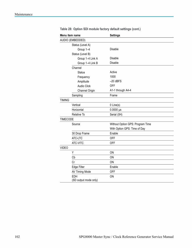
Maintenance
Table 28: Option SDI module factory default settings (cont.)
Menu item name Settings
AUDIO (EMBEDDED)
Status (Level A)
Group 1–4
Status (Level B)
Group 1–4 Link A
Group 1–4 Link B
Disable
Disable
Disable
Channel
Status
Frequency
Amplitude
Audio Click
Channel Origin
Active
1000
–20 dBFS
OFF
A1-1 through A4-4
Sampling Frame
TIMING
Vertical 0 Line(s)
Horizontal 0.0000 μs
Relative To Serial (0H)
TIMECODE
Source Without Option GPS: Program Time
With Option GPS: Time of Day
30 Drop Frame Enable
ATC-LTC OFF
ATC-VITC OFF
VIDEO
Y ON
Cb ON
Cr ON
Edge Filter Enable
AV Timing Mode OFF
EDH(SD output mode only)
ON
102 SPG8000 Master Sync / Clock Reference Generator Service Manual

Maintenance
Table 28: Option SDI module factory default settings (cont.)
Menu item name Settings
ANC PAYLOAD
Output Disable
Parity Automatic
DID 0x101
SDID 0x200
DC 0x101
UDW 0x200
CS 0x200
Auto-Calculate CS Enable
Line 9
Field 1, Line: 9
Field 2, Line: 9
Start Sample 1928
Video Channel Luma
Link Location Link A
Stream Location HS Stream 1
SMPTE 352 PAYLOAD Enable
SECONDARY OUTPUT Test Pattern
SPG8000 Master Sync / Clock Reference Generator Service Manual 103
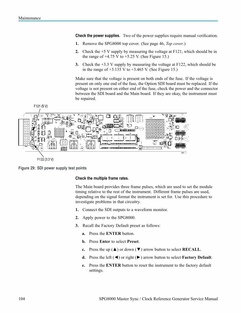
Maintenance
Check the power supplies. Two of the power supplies require manual verification.
1. Remove the SPG8000 top cover. (See page 46, Top cover.)
2. Check the +5 V supply by measuring the voltage at F121, which should be inthe range of +4.75 V to +5.25 V. (See Figure 15.)
3. Check the +3.3 V supply by measuring the voltage at F122, which should bein the range of +3.135 V to +3.465 V. (See Figure 15.)
Make sure that the voltage is present on both ends of the fuse. If the voltage ispresent on only one end of the fuse, the Option SDI board must be replaced. If thevoltage is not present on either end of the fuse, check the power and the connectorbetween the SDI board and the Main board. If they are okay, the instrument mustbe repaired.
Figure 29: SDI power supply test points
Check the multiple frame rates.
The Main board provides three frame pulses, which are used to set the moduletiming relative to the rest of the instrument. Different frame pulses are used,depending on the signal format the instrument is set for. Use this procedure toinvestigate problems in that circuitry.
1. Connect the SDI outputs to a waveform monitor.
2. Apply power to the SPG8000.
3. Recall the Factory Default preset as follows:
a. Press the ENTER button.
b. Press Enter to select Preset.
c. Press the up () or down () arrow button to select RECALL.
d. Press the left () or right () arrow button to select Factory Default.
e. Press the ENTER button to reset the instrument to the factory defaultsettings.
104 SPG8000 Master Sync / Clock Reference Generator Service Manual

Maintenance
4. Verify that all four SDI signal outputs (SDI 1A, SDI 1B, SDI 2A, and SDI2B) are set to provide a 59.94, 1080i format, 100% color bar signal (factorydefault signal).
5. Check the DDS0:Phase and DDS1:Phase lock status, as described in theModule Diagnostics. (See page 98, Check the SDI diagnostics.)
6. Change the SDI signal format to 50 Hz:
a. Press the SDI button until SDI 1 appears on the display.
b. Press the up () or down () arrow button to select FORMAT.
c. Press the left () or right () arrow button to select 1080 50i.
d. Press the ENTER button.
e. Repeat the steps to set the SDI 2 channel to 1080 24p.
7. Check the DDS0:Phase and DDS1:Phase lock status, as described in theModule Diagnostics. (See page 98, Check the SDI diagnostics.)
If one of the formats (59.94 Hz, 50 Hz, or 24 Hz) works correctly, but the otherone does not, the sync pulse may be missing.
To power up in factory mode. Putting the instrument into factory mode allowsaccess to calibration, but it also allows the module to show in the menus even if itfails the POST routine.
Restart the instrument in factory mode. (See page 105, To power up in factorymode.)
1. Run the Check module diagnostics routine. (See page 98, Check the SDIdiagnostics.)
Verify that Option 3G is enabled. If your instrument has Option 3G enabled, anoption key was entered to enable the 3G software option. You need to enter theoption key only once.
Perform the following steps to verify that Option 3G is enabled.
1. Press the front-panel SYSTEM button.
2. Press the up () or down () arrow button until SYSTEM : OPTIONSare displayed.
Press the ENTER button.
3. Press the up () or down () arrow button and check for SYSTEM:OPTIONS : ENABLED: 3G, which indicates that this option is enabled.
SPG8000 Master Sync / Clock Reference Generator Service Manual 105

Maintenance
Download a frame picture with a known good image. If you are having problemswith generating a frame picture using Option SDI, perform the following steps toinstall a known good frame picture so that you can determine whether the problemis with the signal you were trying to generate or with the module:
1. Download one of the sample frame pictures from the SPG8000 SW Libraryand Documentation DVD that shipped with your product. The sample imagesare located in the SAMPLE/SDI7 directory on the DVD.
NOTE. For information on how to transfer or install user files to your SPG8000,refer to the Quick Start User Manual, Tektronix part number 071-3080-XX.
2. Configure the Option SDI to output a 1080i 59.94 format HD signal.
3. Press the SDI button to display SDI 1.
4. Press the up () or down () arrow button to select TEST SIGNAL.
5. Press ENTER.
6. Press the up () or down () arrow button to select FRAME PICTURE.
7. Press the left () or right () arrow button to select the file you downloaded.
8. Press the ENTER button to load that signal into the generator.
9. Check to see if the Option SDI is providing a proper frame picture:
a. If a proper frame picture is generated when using the signal that youdownloaded, but not when using a customer signal, the problem isprobably something in the customer signal.
b. If a proper frame picture is not generated with the signal that youdownloaded, there is probably a problem with the Option SDI.
106 SPG8000 Master Sync / Clock Reference Generator Service Manual

Maintenance
Repackaging instructionsUse the following instructions to prepare your instrument for shipment to aTektronix, Inc., Service Center:
1. Attach a tag to the instrument showing: the owner, complete address andphone number of someone at your firm who can be contacted, the instrumentserial number, and a description of the required service.
2. Package the instrument in the original packaging materials. If the originalpackaging materials are not available, follow these directions:
a. Obtain a carton of corrugated cardboard having inside dimensions six ormore inches greater than the dimensions of the instrument. Use a shippingcarton that has a test strength of at least 250 pounds (113.5 kg).
b. Surround the module with a protective (anti-static) bag.
c. Pack dunnage or urethane foam between the instrument and the carton.If using Styrofoam kernels, overfill the box and compress the kernels byclosing the lid. There should be three inches of tightly packed cushioningon all sides of the instrument.
3. Seal the carton with shipping tape, industrial stapler, or both.
SPG8000 Master Sync / Clock Reference Generator Service Manual 107

Maintenance
108 SPG8000 Master Sync / Clock Reference Generator Service Manual

Replaceable partsThis section contains a list of the replaceable modules for the SPG8000 generatorand available options. Use this list to identify and order replacement parts.
Parts ordering informationReplacement parts are available through your local Tektronix field office orrepresentative.
Changes to Tektronix products are sometimes made to accommodate improvedcomponents as they become available and to give you the benefit of the latestimprovements. Therefore, when ordering parts, it is important to include thefollowing information in your order.
Part number (see Part Number Revision Level below)
Instrument type or model number
Instrument serial number
Instrument modification number, if applicable
If you order a part that was replaced with a different or improved part, your localTektronix field office or representative will contact you concerning any change inpart number.
Part number revision level Tektronix part numbers contain two digits that show the revision level of thepart. For most parts in this manual, you will find the letters XX in place of therevision level number.
When you order parts, Tektronix will provide you with the most current part foryour product type, serial number, and modification (if applicable). At the time ofyour order, Tektronix will determine the part number revision level needed foryour product, based on the information you provide.
SPG8000 Master Sync / Clock Reference Generator Service Manual 109

Replaceable parts
Module servicing Modules can be serviced by selecting one of the following three options. Contactyour local Tektronix service center or representative for repair assistance.
Module exchange. In some cases you may exchange your module for aremanufactured module. These modules cost significantly less than new modulesand meet the same factory specifications. For more information about the moduleexchange program, call 1-800-833-9200. Outside North America, contact aTektronix sales office or distributor; see the Tektronix Web site for a list of offices:www.tektronix.com
Module repair and return. You may ship your module to us for repair, after whichwe will return it to you.
New modules. You may purchase replacement modules in the same way as otherreplacement parts.
Using the replaceable parts listThis section contains a list of the mechanical and/or electrical components that arereplaceable for the SPG8000. Use this list to identify and order replacement parts.The following table describes each column in the parts list.
Table 29: Parts list column descriptions
Column Column name Description
1 Figure & Index Number Items in this section are referenced by figure and index numbers to the explodedview illustrations that follow.
2 Tektronix Part Number Use this part number when ordering replacement parts from Tektronix.
3 and 4 Serial Number Column three indicates the serial number at which the part was first effective.Column four indicates the serial number at which the part was discontinued. Noentries indicates the part is good for all serial numbers.
5 Qty This indicates the quantity of parts used.
6 Name & Description An item name is separated from the description by a colon (:). Because of spacelimitations, an item name may sometimes appear as incomplete. Use the U.S.Federal Catalog handbook H6-1 for further item name identification.
Abbreviations Abbreviations conform to American National Standard ANSI Y1.1-1972.
110 SPG8000 Master Sync / Clock Reference Generator Service Manual

Replaceable parts
Replaceable parts listsThe following tables list the replaceable parts for the SPG8000.
Table 30: Main instrument replaceable parts
Fig. &indexnumber
Tektronix partnumber Qty Name & description
30-1 211-1194-XX 28 SCREW, MACHINE; M3 X 6MM, FLH BLACK, CROSS REC
-2 200-5248-XX 1 CABINET; TOP MAIN CHASSIS
1 POWER SUPPLY ASSY
STANDARD
-3 650-5545-XX
2 POWER SUPPLY ASSY
OPTION DPW
-4 441-2690-XX 1 MAIN CHASSIS ASSY
The chassis assembly has replaceable subparts. (See Figure 31 on page 113.)
-5 650-5547-XX 1 FRONT PANEL ASSY
The Front Panel assembly has replaceable subparts. (See Figure 32 on page 115.)
Figure 30: Main instrument exploded view
SPG8000 Master Sync / Clock Reference Generator Service Manual 111

Replaceable parts
Table 31: Chassis assembly replaceable parts
Fig. &indexnumber
Tektronixpart number Qty Name & description
31-1 441-2691-XX 1 MAIN CHASSIS ASSY
-2 863-0648-XX 1 CIRCUIT BD ASSY; MAIN
-3 211-A245-XX 10 SCREW, MACHINE; M3 X 6 MM L, PNH, STL, NI PL, CROSS REC, W/NUT & LOCK WASHER
-4 344-0629-XX 1 MOUNT, CLIP; WIRE ROUTING CLIP, NYLON 6/6, ADHESIVE BACKING, NATURAL COLOR
-5 174-6138-XX 1 CABLE ASSY, 2 X 5 FEMALE TO FEMALE, KEYED
-6 174-6143-XX 1 CABLE 2 X 8, 2 MM PITCH, RIBBON FEMALE TO FEMALE, TAB
-7 174-6137-XX 1 CAT5E CABLE CABLE ASSEMBLY, RJ45, MALE/MALE, 2 FT
-8 878-0652-XX 1 CIRCUIT BD ASSY: BREAKOUT
-9 214-3903-XX 4 SCREW, JACK; 4-40 X 0.312 EXT THD, 4-40 INT THD, 0.188 HEX, ZINC PLATED STEEL
-10 333-4681-XX 1 REAR PANEL
-11 - - - - 1 CIRCUIT BD ASSY: Genlock/Black board (See Figure 35.)
-12 - - - - 1 OPTION BG ASSY (See Figure 34.)
-13 - - - - 1 OPTION AG ASSY (See Figure 33.)
-14 - - - - 1 OPTION SDI ASSY (See Figure 36.)
-15 348-A156-XX 1 GASKET, SHIELD: FINGER TYPE, BE-CU, 8.13MM W X 2.79MM H X 406.4MM L
-16 119-7933-XX 1 FAN ASSY (12 V, 8.62 CFM) 40 X 40 X 28 MM, TERMINATED
-17 211-A265-XX 2 SCREW, MACHINE; M3 X 40MM L, PNH, STL, NI PL, CROSS REC, W/NUT & LOCK WASHER
-18 407-6120-XX 1 BRACKET PCB, HOLD DOWN
-19 220-A095-XX 2 NUT, PLAIN, HEX:M3, STL, NI PL, W/EXT TOOHED WASHER
-20 878-0650-XX 1 CIRCUIT BD ASSY; POWER COMBINER
-21 211-1194-XX 6 SCREW, MACHINE; M3 X 6MM, FLH BLACK, CROSS REC
-22 146-0109-XX 1 BATTERY, DRY; 3.0 V, LITHIUM MANGANESE DIOXIDE, 210MAH, 20 X 3.22MM COIN CELL WITH SOLDER TABS,CR2032-1HF1
Main board fuses (not shown)
159-5018-XX 2 FUSE; 3.0A, 125 V, FAST BLOW, 0.1 X 0.1 X 0.24, UL REG, CSA CERT
159-5022-XX 15 FUSE; 5.0A, 125 V; FAST BLOW, 0.1 X 0.1 X 0.24, UL REG, CSA CERT; 451005
112 SPG8000 Master Sync / Clock Reference Generator Service Manual

Replaceable parts
Figure 31: Chassis assembly exploded view
SPG8000 Master Sync / Clock Reference Generator Service Manual 113

Replaceable parts
Table 32: Front panel assembly replaceable parts
Fig. &indexnumber
Tektronix partnumber
Serial no.effective
Serial no.discont'd Qty Name & description
32- 650-5546-XX 1 FRONT PANEL ASSY
-1 367-0530-XX 2 HANDLE, BOW; AL, 1.0 X 1.25, STAIN FINISH, SAFETY CONTROLLED
-2 335-2801-XX 1 LABEL, FRONT PANEL
-3 426-2637-XX 1 FRONT PANEL BEZEL
-4 348-2061-XX 2 GASKET, DISPLAY DUST SEAL
-5 211-A245-XX 13 SCREW, MACHINE; M3 X 6 MM L, PNH, STL, NI PL, CROSS REC, W/NUT & LOCKWASHER
-6 119-7930-XX 1 DISPLAY MODULE ASSEMBLY
-7 407-5730-XX 1 FRONT PANEL SUPPORT BRACKET
-8 211-0738-XX 4 SCREW, MACHINE; 6-32 X 0.625, PNH, STL BLK ZI, TORX
-9 174-6136-XX 1 CABLE, RIBBON, LCD, 2X8, 0.100 P FEMALE TO FEMALE
-11 174-6135-XX 1 CABLE 2 X 13, RIBBON, KEYBOARD FEMALE TO FEMALE
-12 131-6521-XX 1 CONTACT, ELEC; EMI, CLIP-ON, 0.38 L X 0.460 W (2 CONTACTS) X 0.45 HIGH,ELECTROLESS NICKEL PLATE
-13 878-0649-XX 1 CIRCUIT BD ASSY; FRONT PANEL
-14 260-2952-XX 1 SWITCH KEYPAD; ELASTOMERIC MAT
-15 354-0025-XX 2 RING, RETAINING; EXTERNAL, U/O 0.187 DIA SFT, ZINC PLATED STEEL
-16 213-0216-XX 2 THUMBSCREW; 10-32 X 0.85, 0.375 OD HD, ZINC PLATED STEEL, W/SLOT
114 SPG8000 Master Sync / Clock Reference Generator Service Manual

Replaceable parts
Figure 32: Front panel assembly exploded view
SPG8000 Master Sync / Clock Reference Generator Service Manual 115
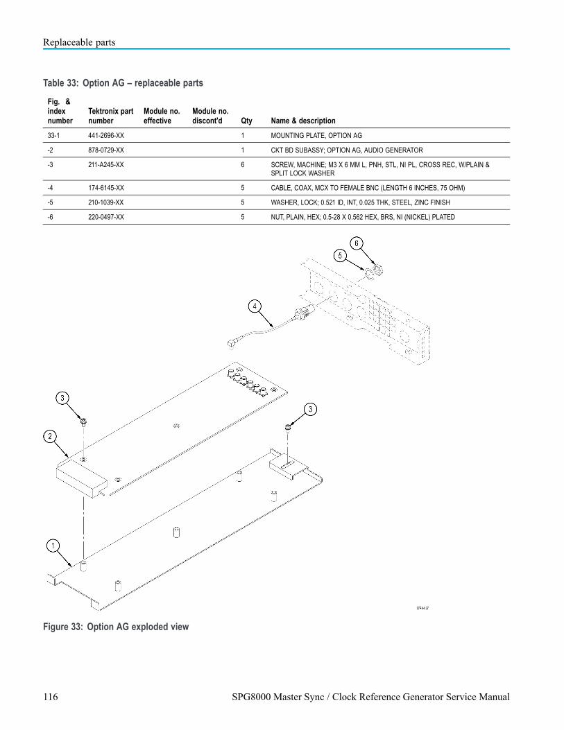
Replaceable parts
Table 33: Option AG – replaceable parts
Fig. &indexnumber
Tektronix partnumber
Module no.effective
Module no.discont'd Qty Name & description
33-1 441-2696-XX 1 MOUNTING PLATE, OPTION AG
-2 878-0729-XX 1 CKT BD SUBASSY; OPTION AG, AUDIO GENERATOR
-3 211-A245-XX 6 SCREW, MACHINE; M3 X 6 MM L, PNH, STL, NI PL, CROSS REC, W/PLAIN &SPLIT LOCK WASHER
-4 174-6145-XX 5 CABLE, COAX, MCX TO FEMALE BNC (LENGTH 6 INCHES, 75 OHM)
-5 210-1039-XX 5 WASHER, LOCK; 0.521 ID, INT, 0.025 THK, STEEL, ZINC FINISH
-6 220-0497-XX 5 NUT, PLAIN, HEX; 0.5-28 X 0.562 HEX, BRS, NI (NICKEL) PLATED
Figure 33: Option AG exploded view
116 SPG8000 Master Sync / Clock Reference Generator Service Manual

Replaceable parts
Table 34: Option BG – replaceable parts
Fig. &indexnumber
Tektronixpart number
Serial no.effective
Serial no.discont'd Qty Name & description
34-1 441-2693-XX 1 MOUNTING PLATE; OPTION BG
-2 878-0728-XX 6 CKT BD ASSY; OPTION BG
-3 211-A245-XX 7 SCREW, MACHINE; M3 X 6 MM L, PNH, STL, NI PL, CROSS REC, W/PLAIN &SPLIT LOCK WASHER
-4 174-B847-XX 4 CA ASSY, RF; 75 OHM, COAX, RG179, 7.5 CM L, BNC TO MCX; OPTION AG
-5 210-1039-XX 4 WASHER, LOCK; 0.521 ID, INT, 0.025 THK, STEEL, ZINC FINISH
-6 220-0497-XX 4 NUT, PLAIN, HEX; 0.5-28 X 0.562 HEX, BRS, NI (NICKEL) PLATED
Figure 34: Option BG exploded view
SPG8000 Master Sync / Clock Reference Generator Service Manual 117

Replaceable parts
Table 35: Genlock/Black board and Option GPS Receiver board – replaceable parts
Fig. &indexnumber
Tektronixpart number
Serial no.effective
Serial no.discont'd Qty Name & description
35-1 441-2694-XX 1 MOUNTING PLATE: GENLOCK/BLACK GENERATOR BOARD
-2 878-0737-XX 1 CIRCUIT BD ASSY; GENLOCK/BLACK GENERATOR
-3 211-A245-XX 4 SCREW, MACHINE; M3 X 6 MM L, PNH, STL, NI PL, CROSS REC, W/PLAIN &SPLIT LOCK WASHER
-4 174-5521-XX 1 CABLE, 2X4, 2MM PITCH, FEMALE TO FEMALE SQUARE PINS
OPTION GPS ONLY
-5 211-0408-XX 4 SCR, ASSY, WSHR; 4-40 X 0.250, PNH, STEEL, ZINC FINISH, T-10 TORX DR,SEMS
OPTION GPS ONLY
-6 119-7518-XX C010100 C010999 1 CIRCUIT BD ASSY: OPTION GPS RECEIVER BOARD (GPS ONLY)
OPTION GPS ONLY
119-8313-XX C011000 1 CIRCUIT BD ASSY: OPTION GPS RECEIVER BOARD (GPS & GLONASS)
OPTION GPS ONLY
-7 174-5509-XX 1 CABLE, FEMALE SMB TO FEMALE BNC
OPTION GPS ONLY
-8 335-1117-XX 1 LIGHT PIPE, SINGLE LED (ELMA P/N 90-1216-1001)
OPTION GPS ONLY
-9 210-1039-XX 5 WASHER, LOCK; 0.521 ID, INT, 0.025 THK, STEEL, ZINC FINISH
-10 220-0497-XX 5 NUT, PLAIN, HEX; 0.5-28 X 0.562 HEX, BRS, NI (NICKEL) PLATED
-11 174-6141-XX 2 CABLE, COAXIAL, MCX TO FEMALE BNC (LENGTH 8 INCHES, 75 OHM)
-12 174-6142-XX 1 CABLE, COAXIAL, MCX TO FEMALE BNC (LENGTH-11 INCHES, 75 OHM)
118 SPG8000 Master Sync / Clock Reference Generator Service Manual

Replaceable parts
Figure 35: Genlock/Black generator board and Option GPS Receiver board exploded view
SPG8000 Master Sync / Clock Reference Generator Service Manual 119

Replaceable parts
Table 36: Option SDI – replaceable parts
Fig. &indexnumber
Tektronixpart number
Serial no.effective
Serial no.discont'd Qty Name & description
36–1 441-2695-XX 1 MOUNTING PLATE; SDI
-2 878-0580-XX 1 CIRCUIT BD ASSY; SDI
-3 211-A245-XX 6 SCREW, MACHINE; M3 X 6 MM L, PNH, STL, NI PL, CROSS REC, W/PLAIN &SPLIT LOCK WASHER
-4 211-0408-XX 2 SCR, ASSY, WSHR; 4-40 X 0.250, PNH, STEEL, ZINC FINISH, T-10 TORX DR,SEMS
-5 878-0602-XX 2 CIRCUIT BD ASSY; OUTPUT
-6 210-1039-XX 4 WASHER, LOCK; 0.521 ID, INT, 0.025 THK, STEEL, ZINC FINISH
-7 220-0497-XX 4 NUT, PLAIN, HEX; 0.5-28 X 0.562 HEX, BRS, NI (NICKEL) PLATED
-8 348-1944-XX 1 GAP PAD 3000S30
-9 214-5166-XX 1 HEATSINK, PCB TO CHASSIS
-10 211-0101-XX 3 SCREW, MACHINE; 4-40 X 0.25, FLH, 100 DEG, ZINC PLATED STEEL, T8
120 SPG8000 Master Sync / Clock Reference Generator Service Manual

Replaceable parts
Figure 36: Option SDI board and Option SDI Output board exploded view
SPG8000 Master Sync / Clock Reference Generator Service Manual 121

Replaceable parts
Table 37: Standard and optional accessories for the SPG8000
Componentnumber
Tektronixpart number
Serial no.effective
Serial no.discont'd Qty Name & description
STANDARD ACCESSORIES
351-1137-XX 1 RACK, KIT, RAILS
063-4474-XX 1 DVD, SOFTWARE LIBRARY & DOCUMENTATION
071-3080-XX 1 QUICK START USER MANUAL, ENGLISH
077-0745-XX 1 QUICK START USER MANUAL, JAPANESE
077-0746-XX 1 QUICK START USER MANUAL, RUSSIAN
161-0364-XX 1 CABLE ASSY, PWR; 3, 18 AWG, 125 V/10 A, 2M, STR, IEC320, C13, RCPT, NEMA5-15P, V-LOCK, US, SAFETY CONTROLLED
STANDARD
POWER CORDS
161-0364-XX 1 OPTION A0: NORTH AMERICA
CABLE ASSY, PWR; 3, 18 AWG, 125 V/10 A, 2M, STR, IEC320, C13, RCPT, NEMA5-15P, V-LOCK, US, SAFETY CONTROLLED
161-0365-XX 1 OPTION A1: UNIVERSAL EURO
CABLE ASSY, PWR; 3, 1MM SQ, 250 V/10 A, 2M, STR, IEC320, C13, RCPT, CEE7 / VII, V-LOCK, EURO, SAFETY CONTROLLED
161-0366-XX 1 OPTION A2: UNITED KINGDOM
CABLE ASSY, PWR; 3, 1MM SQ, 250 V/10 A, 2M, STR, IEC320, C13, RCPT,BS1363, V-LOCK, UK, SAFETY CONTROLLED
161-0367-XX 1 OPTION A3: AUSTRALIA
CABLE ASSY, PWR; 3, 1MM SQ, 250 V/10 A, 2M, STR, IEC320, C13, RCPT,AS3112, V-LOCK, AUSTRALIA, SAFETY CONTROLLED
161-0368-XX 1 OPTION A5: SWITZERLAND
CABLE ASSY, PWR; 3, 1MM SQ, 250 V/10 A, 2M, STR, IEC320, C13, RCPT,SEV 1011, V-LOCK, SWISS, WITH PARTIALLY INSULATED PINS; SAFETYCONTROLLED; CIQB
161-0369-XX 1 OPTION A6: JAPAN
CABLE ASSY, PWR; 3, 1.25MM SQ, 125 V/12 A, 2M, STR, IEC320, C13, RCPT,JIS 8303, V-LOCK, JAPAN, SAFETY CONTROLLED
161-0370-XX 1 OPTION A10: CHINA
CABLE ASSY, PWR; 3, 1MM SQ, 250 V/10 A, 2M, STR, IEC320, C13, RCPT, GB2099, V-LOCK, CHINA, SAFETY CONTROLLED
161-0400-XX 1 OPTION A11: INDIA
CABLE ASSY, PWR; 3, 1.0 MM SQ, 250 V/6 A, 2.5 METER, STR, IEC320/C13,RCPT, PLUG, INDIA
161-0356-XX 1 OPTION A12: BRAZIL
CABLE ASSY, PWR; 3, 1.00MM SQ, 250 V/10 A, 2.5 METER, RT ANGLE,IEC320/C13 CERTIFICATION, RCPT, BRAZIL, SAFETY CONTROLLED
122 SPG8000 Master Sync / Clock Reference Generator Service Manual

Replaceable parts
SPG8000 Master Sync / Clock Reference Generator Service Manual 123