Frequency Counting Using Arduino Objectives - Tektronix
11
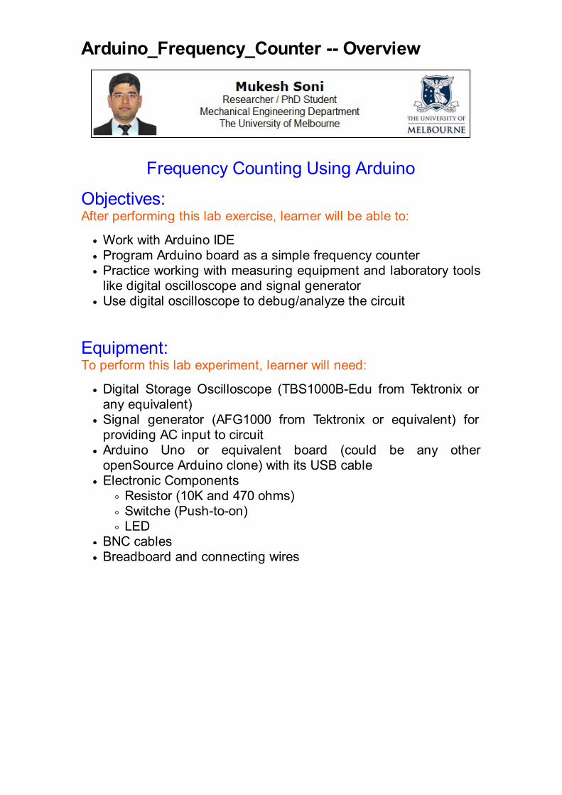
Arduino_Frequency_Counter -- Overview Frequency Counting Using Arduino Objectives: After performing this lab exercise, learner will be able to: Work with Arduino IDE Program Arduino board as a simple frequency counter Practice working with measuring equipment and laboratory tools like digital oscilloscope and signal generator Use digital oscilloscope to debug/analyze the circuit Equipment: To perform this lab experiment, learner will need: Digital Storage Oscilloscope (TBS1000B-Edu from Tektronix or any equivalent) Signal generator (AFG1000 from Tektronix or equivalent) for providing AC input to circuit Arduino Uno or equivalent board (could be any other openSource Arduino clone) with its USB cable Electronic Components Resistor (10K and 470 ohms) Switche (Push-to-on) LED BNC cables Breadboard and connecting wires
-
Upload
khangminh22 -
Category
Documents
-
view
0 -
download
0
Transcript of Frequency Counting Using Arduino Objectives - Tektronix
Arduino_Frequency_Counter -- Overview
Frequency Counting Using Arduino
Objectives:After performing this lab exercise, learner will be able to:
Work with Arduino IDE Program Arduino board as a simple frequency counterPractice working with measuring equipment and laboratory tools like digital oscilloscope and signal generatorUse digital oscilloscope to debug/analyze the circuit
Equipment:To perform this lab experiment, learner will need:
Digital Storage Oscilloscope (TBS1000B-Edu from Tektronix or any equivalent)Signal generator (AFG1000 from Tektronix or equivalent) for providing AC input to circuitArduino Uno or equivalent board (could be any other openSource Arduino clone) with its USB cableElectronic Components
Resistor (10K and 470 ohms)Switche (Push-to-on)LED
BNC cables Breadboard and connecting wires
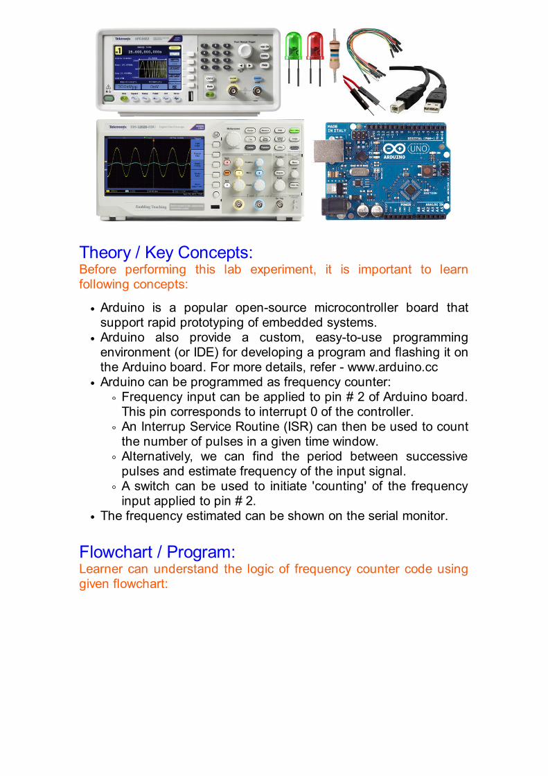
Theory / Key Concepts:Before performing this lab experiment, it is important to learn following concepts:
Arduino is a popular open-source microcontroller board that support rapid prototyping of embedded systems.Arduino also provide a custom, easy-to-use programming environment (or IDE) for developing a program and flashing it on the Arduino board. For more details, refer - www.arduino.ccArduino can be programmed as frequency counter:
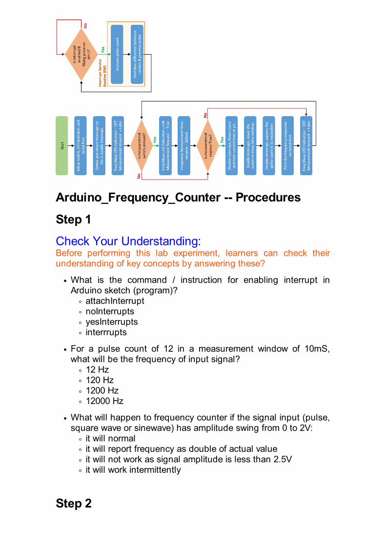
Frequency input can be applied to pin # 2 of Arduino board. This pin corresponds to interrupt 0 of the controller.An Interrup Service Routine (ISR) can then be used to count the number of pulses in a given time window.Alternatively, we can find the period between successive pulses and estimate frequency of the input signal.A switch can be used to initiate 'counting' of the frequency input applied to pin # 2.
The frequency estimated can be shown on the serial monitor.
Flowchart / Program:Learner can understand the logic of frequency counter code using given flowchart:
Arduino_Frequency_Counter -- Procedures
Step 1
Check Your Understanding:Before performing this lab experiment, learners can check their understanding of key concepts by answering these?
What is the command / instruction for enabling interrupt in Arduino sketch (program)?
attachInterruptnoInterruptsyesInterruptsinterrrupts
For a pulse count of 12 in a measurement window of 10mS, what will be the frequency of input signal?
12 Hz120 Hz1200 Hz12000 Hz
What will happen to frequency counter if the signal input (pulse, square wave or sinewave) has amplitude swing from 0 to 2V:
it will normalit will report frequency as double of actual valueit will not work as signal amplitude is less than 2.5Vit will work intermittently
Step 2

Circuit diagram / Connection DetailsUsing the jumper / connecting wires prepare the circuit as shown below - Choose Rpullup = 10K & RLED = 470 ohm.Feed the output from AFG / Signal Generator to pin 2 of the Arduino
Step 3
Experiment SetupMake the arrangement as shown in figure below (Arduino clone is being
used here) -
PC is connected to Arduino via USB cableUse AFG to generate a square wave and connect AFG output to pin 2 of ArduinoConnect oscilloscope channel 1 to AFG output so that same signal is viewable on oscilloscope (that is fed to Arduino)
Step 4
Make the Circuit WorkFlash the code on ArduinoUse signal from AFG/signal generator to feed at Pin 2 of ArduinoSet square wave from channel 1 of the AFG
amplitude = 0 - 3V frequency = 1K Hz
Autoset the oscilloscope to see this waveformsPress the button on Arduino pin 7 - You should see the measurent LED getting ON for a moment and frequency value appearing on Serial Monitor on PC.
Step 5
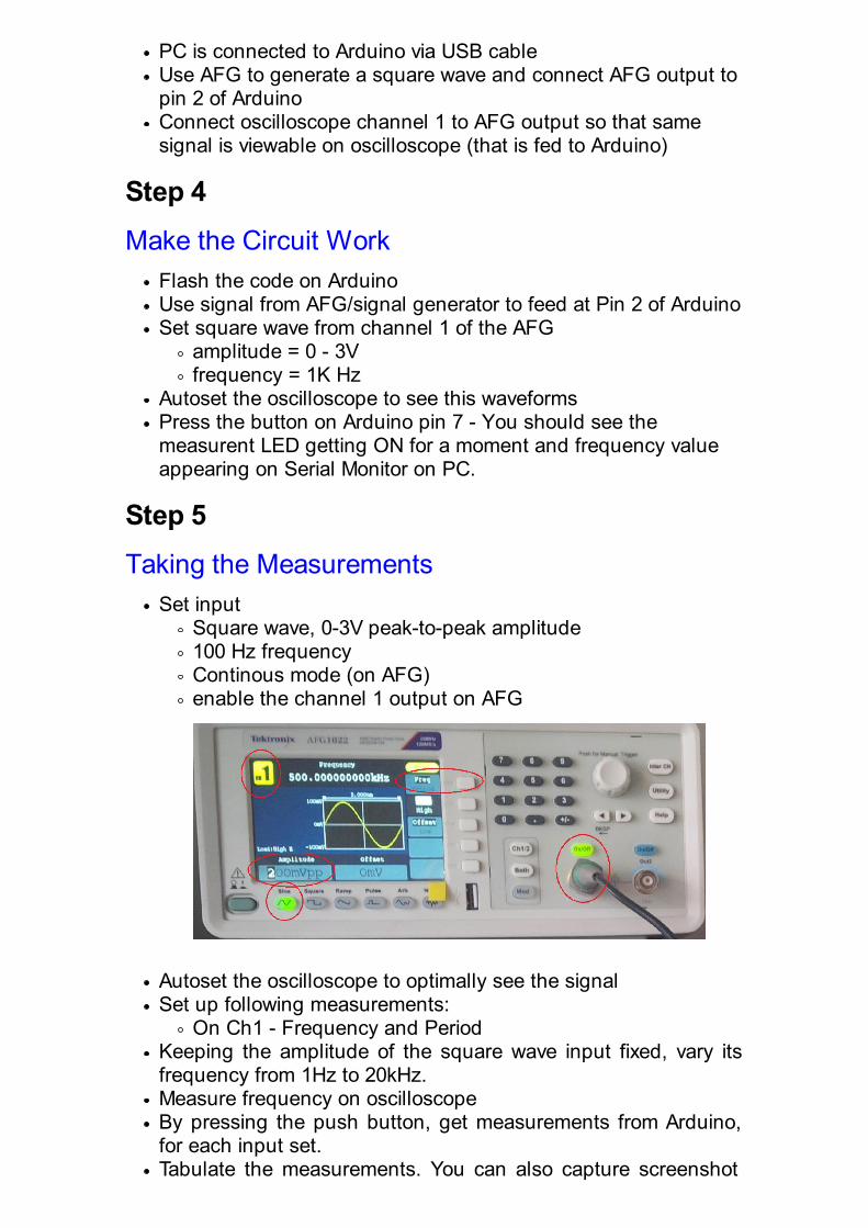
Taking the MeasurementsSet input
Square wave, 0-3V peak-to-peak amplitude100 Hz frequencyContinous mode (on AFG)enable the channel 1 output on AFG
Autoset the oscilloscope to optimally see the signalSet up following measurements:
On Ch1 - Frequency and PeriodKeeping the amplitude of the square wave input fixed, vary its frequency from 1Hz to 20kHz. Measure frequency on oscilloscopeBy pressing the push button, get measurements from Arduino, for each input set.Tabulate the measurements. You can also capture screenshot

for each measurement set.
Step 6
Analyzing the ResultThe observation table would look like as shown below. Calculate the % deviation of frequency measured by Arduino from actual.
Create a plot of Arduino Vs Actual frequency values

Plot the % deviation with respect to actual frequency values
Can you guess why the deviation increases to 4% for 20kHz signal?
Step 7
ConclusionThe analysis of the observed results confirm that (As expected):
The Arduino can be used for frequency counter applicationFrequency measured by Arduino system matches the actual frequency value of the inputDeviation increases as the input frequency is increases beyond 10KHz
How to program Arduino?
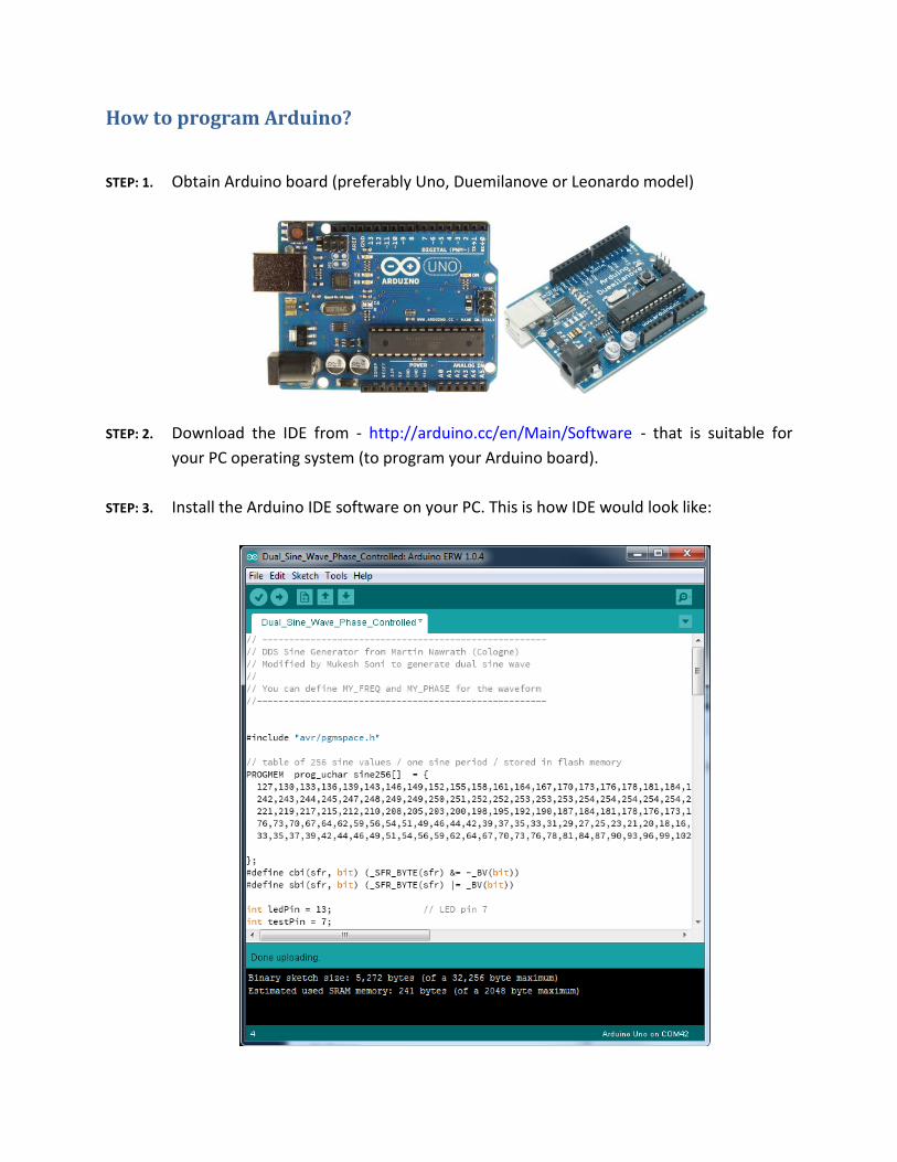
STEP: 1. Obtain Arduino board (preferably Uno, Duemilanove or Leonardo model)
STEP: 2. Download the IDE from - http://arduino.cc/en/Main/Software - that is suitable for
your PC operating system (to program your Arduino board).
STEP: 3. Install the Arduino IDE software on your PC. This is how IDE would look like:

STEP: 4. Connect the Arduino board using USB cable provided to your PC. Wait till the
necessary drivers are installed and device is recognized as COM port.
STEP: 5. Select the correct Arduino Board type as show below: Tools > Board >
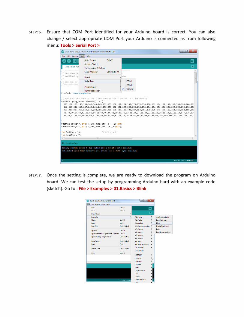
STEP: 6. Ensure that COM Port identified for your Arduino board is correct. You can also
change / select appropriate COM Port your Arduino is connected as from following
menu: Tools > Serial Port >
STEP: 7. Once the setting is complete, we are ready to download the program on Arduino
board. We can test the setup by programming Arduino bard with an example code
(sketch). Go to : File > Examples > 01.Basics > Blink
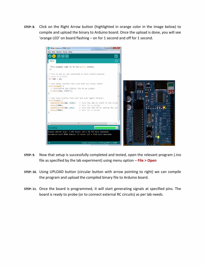
STEP: 8. Click on the Right Arrow button (highlighted in orange color in the image below) to
compile and upload the binary to Arduino board. Once the upload is done, you will see
‘orange LED’ on board flashing – on for 1 second and off for 1 second.
STEP: 9. Now that setup is successfully completed and tested, open the relevant program (.ino
file as specified by the lab experiment) using menu option – File > Open
STEP: 10. Using UPLOAD button (circular button with arrow pointing to right) we can compile
the program and upload the compiled binary file to Arduino board.
STEP: 11. Once the board is programmed, it will start generating signals at specified pins. The
board is ready to probe (or to connect external RC circuits) as per lab needs.