SPECIFICATION NO. 1338W - Eastern Municipal Water District
688
Riverside County Perris, California SPECIFICATION NO. 1338W PERRIS II DESALINATION FACILITY VOLUME III of IV OCTOBER 2018 Work Order #413511 A PUBLIC WORKS PROJECT Contents: Specifications | Notice Inviting Bids | Bidding Requirements | Bid Forms | Contract Forms | Conditions of Contract Paul D. Jones, II, P.E. - General Manager Safety is of paramount and overriding importance to Eastern Municipal Water District Visit our website at www.emwd.org to view currently advertised projects Navigate to Construction Construction Bid Opportunities
-
Upload
khangminh22 -
Category
Documents
-
view
0 -
download
0
Transcript of SPECIFICATION NO. 1338W - Eastern Municipal Water District

Riverside County Perris, California
SPECIFICATION NO. 1338W PERRIS II DESALINATION FACILITY
VOLUME III of IV
OCTOBER 2018 Work Order #413511 A PUBLIC WORKS PROJECT
Contents:
Specifications | Notice Inviting Bids | Bidding Requirements | Bid Forms | Contract Forms | Conditions of Contract
Paul D. Jones, II, P.E. - General Manager Safety is of paramount and overriding importance to Eastern Municipal Water District
Visit our website at www.emwd.org to view currently advertised projects Navigate to Construction Construction Bid Opportunities

[PAGE LEFT INTENTIONALLY BLANK]

Page 1 of 2
EASTERN MUNICIPAL WATER DISTRICT
SPECIFICATION NO. 1338W
PERRIS II DESALINATION FACILITY
In accordance with the provisions of the Business and Professions Code of the State of California,
these contract documents have been prepared under the general supervision and direction of
the following professional engineers, licensed in the State of California.
David A. Cover – Civil / Mechanical
Philip D. Rishel – Architectural
James R. Lievers – Landscape
Randy W. Cantrell – Building Mechanical
10/8/2018
10/8/2018

Page 2 of 2
Mark A Lowe – Structural
Holly S. Murakami – Electrical
Jose Charcas – Instrumentation
10/8/2018

00010-1 Table of Contents
TABLE OF CONTENTS
VOLUME I OF IV
BIDDING REQUIREMENTS PAGE 00010 Table of Contents 00012 Notice Inviting Bids NIB-1 thru NIB-8 00014 Bid Opening Map 00016 Bid Walk-thru map/directions 00018 Instructions to Bidders B-1 thru -6 00020 Bidding Sheets & Equipment & Material List (submit with bid) BS-1 thru BS-14 00024 Proposal (7 day) (submit with bid) C3-1 thru -2 00028 Designation of Subcontractors (submit with bid) C5a thru e 00030 Contractor's Licensing Statement (submit with bid) C6-1 thru -2 00032 Non-Collusion Declaration (submit with bid) C7-1 thru -2 00034 Agreement C8a thru d 00036 Performance Bond C9-1 thru -4 00038 Payment Bond C10-1 thru -4 00040 Bid Bond (submit with bid) BB-1 00042 Worker’s Compensation Insurance Certificate C11-1 thru -2 00044 Certificate of Insurance Sample C12 00046 Iran Contracting Act Certification (submit with bid if over $1million) C13-1 thru -4 00048 Maintenance Bond (by Contractor) - Pumping Equipment C14-1 thru -2 00049 Maintenance Bond (by Supplier) - Pumping Equipment C14.1 thru -2 00050 Cal-OSHA form 300A (submit with bid) C16-1 thru -2 00054 Pipe Zone Density Chart (CCP, CML&C, DIP, HDPE, PVC) C18 00056 Employee Safety & Health Training Records C19-1 thru -2 00057 Contractor Registration Extract(s) (submit with bid) C22-1 thru -2 GENERAL CONDITIONS 00062 Section E, Inspection & Tests E-1 thru E-2 00064 Section F, Labor & Construction F-1 thru F-58 Includes Exhibit A – Escrow Agreement 00066 Section H, Permits H-1 thru H-2 SPECIAL CONDITIONS 00100 Special Conditions SC-1 thru SC-36 00110 Supplemental Special Conditions SSC-1 thru SSC-14 00120 Supplemental Special Conditions (Funding) SSC1-1 thru SSC1-2

00010-2 Table of Contents
CONTRACT DRAWINGS PAGE 00200 Section P Standard & Construction Drawings (list) P-1 thru P-16 EMWD DETAILED PROVISIONS DIVISION 1 – GENERAL REQUIREMENTS 01000 General Safety Requirements 1 thru 8 01026 Schedule of Values 1 thru 22 01140 Work Restrictions and Constraints (Custom) 1 thru 8 01310 Project Control Schedule 1 thru 12 01380 Pre-Construction Audio Video Taping 1 thru 4 01381 Pre-Const. Audio Video Taping Above Ground Facilities 1 thru 4 01430 Maintenance Manual Requirements 1 thru 12 01450 Code Required Special Inspections and Procedures (Custom) 1 thru 46 01500 Temporary Facilities and Controls 1 thru 14 01611 Meteorological and Seismic Design Criteria (Custom) 1 thru 10 01614 Product Delivery, Storage, and Handling (Custom) 1 thru 4 01615 Equipment and Valve Identification (Custom) 1 thru 6 01630 Pipeline Schedule (Custom) 1 thru 8 01650 Commissioning (Custom) 1 thru 18 01820 Demonstration and Training (Custom) 1 thru 4 DIVISION 02 – SITEWORK 02050 Demolition and Salvage 1 thru 2 02082 Removal and Disposal of Asbestos Containing Materials (Custom) 1 thru 4 02200 Earthwork (Custom) 1 thru 22 02221 Trenching, Backfilling, and Compacting 1 thru 10 02242 Cement Stabilization Sand Bedding/Backfill 1 thru 2 02252 Control Density Fill 1 thru 4 02271 Grouted Rip-Rap 1 thru 4 02433 Drainage Pipe-Reinforced Concrete Pipe - Storm Drain 1 thru 4 02444 Chain Link Fencing 1 thru 6 02505 Roadway Base Course 1 thru 4 02513 Asphalt Concrete Paving 1 thru 4 02718 Installation of Water Pipeline 1 thru 22 02762 Furnish & Install Plastic Sewer Pipe System 1 thru 14 02810 Fabricated Metal Gates and Fencing (Custom) 1 thru 6 02813 Irrigation (Custom) 1 thru 24 02900 Landscape (Custom) 1 thru 20

00010-3 Table of Contents
DIVISION 03 – CONCRETE PAGE 03150 Formwork for Cast-in-Place Concrete 1 thru 6 03200 Reinforcing 1 thru 6 03300 Cast-in-Place Concrete 1 thru 38 03450 Architectural Precast Concrete (Custom) 1 thru 14 03480 Precast Reinforced Concrete Vaults (Custom) 1 thru 6 03930 Concrete Crack Repair (Custom) 1 thru 6
DIVISION 04 – MASONRY 04200 Masonry (Custom) 1 thru 18 04210 Cast Stone (Custom) 1 thru 8
DIVISION 05 – METALS 05100 Structural Metals 1 thru 6 05210 Steel Joist Decking (Custom) 1 thru 6 05312 Steel Decking (Custom) 1 thru 4 05520 Metal Railings (Custom) 1 thru 6 05530 Metal Gratings (Custom) 1 thru 8 05550 Anchorage in Concrete and Masonry (Custom) 1 thru 8 05600 Standards for Aluminum Work 1 thru 8
VOLUME II OF IV
DIVISION 06 - WOOD & PLASTICS 06100 Rough Carpentry (Custom) 1 thru 4 06500 Finish Carpentry and Architectural Woodwork (Custom) 1 thru 6 06610 FRP Grating Floor System Supported by Pedestals (Custom) 1 thru 8 06640 Plastic Lining For Concrete Structures 1 thru 6
DIVISION 07 - THERMAL AND MOISTURE PROTECTION 07160 Dampproofing (Custom) 1 thru 2 07200 Thermal Insulation (Custom) 1 thru 2 07240 Exterior Insulation and Finish System (Custom) 1 thru 6 07535 Thermoplastic Polyolefin Roofing (Custom) 1 thru 8 07600 Sheet Metal (Custom) 1 thru 4 07700 Roof Specialties and Accessories (Custom) 1 thru 4 07840 Firestopping (Custom) 1 thru 6 07900 Joint Sealants (Custom) 1 thru 4
DIVISION 08 - DOORS AND WINDOWS 08110 Steel Doors and Frames (Custom) 1 thru 4 08115 FRP Doors and Frames (Custom) 1 thru 4 08305 Floor Access Doors and Hatches (Custom) 1 thru 4

00010-4 Table of Contents
DIVISION 08 – DOORS AND WINDOWS (Continued) PAGE 08331 Overhead Coiling Aluminum Doors (Custom) 1 thru 8 08410 Aluminum Entrances and Assemblies (Custom) 1 thru 8 08700 Finish Hardware (Custom) 1 thru 10 08800 Glass and Glazing (Custom) 1 thru 4 08950 Translucent Wall Panel System (Custom) 1 thru 8
DIVISION 09 - FINISHES 09250 Gypsum Wallboard (Custom) 1 thru 6 09310 Ceramic Tile (Custom) 1 thru 4 09510 Acoustical Ceilings and Wall Systems (Custom) 1 thru 6 09660 Resilient Flooring (Custom) 1 thru 4 09680 Carpet (Custom) 1 thru 4 09725 Resinous Flooring (Custom) 1 thru 6 09810 Tape Wrap for Insulated Joints 1 thru 2 09880 Corrosion Protection Lining Systems (Custom) 1 thru 12 09892 Worker and Environmental Protection and Transportation and Disposal of Hazard 1 thru 6 09900 Protective Coatings (Custom) 1 thru 26 09920 Architectural Painting (Custom) 1 thru 10
DIVISION 10 - SPECIALTIES 10200 Louvers and Vents (Custom) 1 thru 4 10400 Identifying Devices (Custom) 1 thru 10 10500 Metal Lockers (Custom) 1 thru 4 10800 Toilet Accessories (Custom) 1 thru 2 10990 Miscellaneous Specialties (Custom) 1 thru 4 DIVISION 11 - EQUIPMENT 11005 General Mechanical and Equipment Provisions 1 thru 18 11115 Horizontal End Suction Pumps (Custom) 1 thru 12 11140 Vertical Diffusion Vane Pumps (Custom) 1 thru 18 11185 Submersible Sample Pumps (Custom) 1 thru 2 11293 Slide Gates (Custom) 1 thru 6 11401 Forced Draft Decarbonator System (Custom) 1 thru 20 11403 Cartridge Filters (Custom) 1 thru 6 11532 In-Line Static Mixer (Custom) 1 thru 8 11727 Liquid Chemical Feed Equipment (Custom) 1 thru 32
DIVISION 12 - FURNISHING 12625 Laboratory Furniture (Custom) 1 thru 6

00010-5 Table of Contents
DIVISION 13 - SPECIAL CONSTRUCTION PAGE 13025 Low Pressure Reverse Osmosis System (Custom) 1 thru 66 13123 Electrical Panel Sunshade Structure 1 thru 10 13190 Fiberglass Reinforced Plastic Chemical Storage Tanks (Custom) 1 thru 8 13190DS Fiberglass Reinforced Plastic Chemical Storage Tanks Data Sheet (Custom) 1 thru 8 13191 Polyethylene Chemical Storage Tanks (Custom) 1 thru 8 13192 Steel Chemical Storage Tanks (Custom) 1 thru 8 13192DS Steel Chemical Storage Tanks Data Sheet (Custom) 1 thru 2 13199 Chemical Storage Tank Installation (Custom) 1 thru 2 13300 Self Supporting Communication Tower (Custom) 1 thru 14 13500 Instrumentation and Control System (Custom) 1 thru 22 13500A Instrument List 1 thru 10 13500B IO List 1 thru 15 13510 Computer System Hardware (Custom) 1 thru 4 13520 Computer System Software (Custom) 1 thru 10 13530 Programmable Logic Controllers (Custom) 1 thru 12 13550 Software Control Block Descriptions (Custom) 1 thru 104 13561 Panel Mounted Instruments (Custom) 1 thru 6 13562 Flow Instruments (Custom) 1 thru 10 13563 Pressure and Level Instruments (Custom) 1 thru 12 13564 Process Analytical Instruments (Custom) 1 thru 10 13565 Temperature Instruments (Custom) 1 thru 4 13566 Miscellaneous Instruments (Custom) 1 thru 4 13570 Panels, Consoles and Appurtenances (Custom) 1 thru 12 13580 Uninterruptible Power Supply (Custom) 1 thru 6 13590 Network Systems (Custom) 1 thru 8 13591 Metallic and Fiber Optic Communication Cables and Connectors (Custom) 1 thru 4 13592 Fiber Optic Cable and Equipment (Custom) 1 thru 30 13750 Tightness Testing of Structures (Custom) 1 thru 4 13930 Fire-Suppression Sprinkler System (Custom) 1 thru 14
DIVISION 14 - CONVEYING SYSTEMS – NOT USED
VOLUME III OF IV DIVISION 15 - MECHANICAL 15010 Valve Installation (Custom) 1 thru 6 15011 Gate Installation (Custom) 1 thru 4 15020 Miscellaneous Piping and Accessories Installation (Custom) 1 thru 14

00010-6 Table of Contents
DIVISION 15 – MECHANICAL (Continued) PAGE 15050 Basic Mechanical Building Systems Material and Methods (Custom) 1 thru 8 15061 Steel Pipe (Custom) 1 thru 36 15061F1 Steel Pipe Fittings Figure 1 1 thru 2 15062 Miscellaneous Piping and Pipe Accessories (Custom) 1 thru 4 15063 Stainless Steel Pipe and Alloy Pipe, Tubing and Accessories (Custom) 1 thru 8 15064 Polyvinyl Chloride (PVC) Pressure Pipe (Custom) 1 thru 8 15065 Miscellaneous Steel Pipe, Tubing and Accessories (Custom) 1 thru 6 15067 Miscellaneous Plastic Process Pipe, Tubing and Accessories (Custom) 1 thru 10 15069 Cast Iron Soil Pipe and Accessories (Custom) 1 thru 2 15070 Copper Tubing and Accessories (Custom) 1 thru 4 15071 Fiberglass Reinforced Plastic Pressure Pipe (Custom) 1 thru 10 15077 Grooved Couplings 1 thru 2 15081 Gaskets 1 thru 2 15089 Nuts and Bolts 1 thru 2 15091 Miscellaneous Ball Valves (Custom) 1 thru 12 15092 Industrial Butterfly Valves (Custom) 1 thru 16 15093 Check Valves (Custom) 1 thru 12 15094 Backflow Preventers (Custom) 1 thru 2 15095 Solenoid Valves (Custom) 1 thru 4 15096 Globe Valves (Custom) 1 thru 4 15097 Pinch and Diaphragm Valves (Custom) 1 thru 6 15098 Miscellaneous Plug Valves (Custom) 1 thru 4 15099 Pressure Reducing Valves (Custom) 1 thru 8 15100 Miscellaneous Valves (Custom) 1 thru 6 15102 Resilient-Seated Gate Valves 1 thru 4 15102S Resilient-Seated Gate Valves Schedule 1 thru 2 15103 Butterfly Valves 1 thru 4 15103S AWWA Butterfly Valves Schedule 1 thru 2 15104 V-Port Ball Valves (Custom) 1 thru 4 15108 Air Valves (Custom) 1 thru 8 15115 Flap Gates (Custom) 1 thru 4 15140 Pipe Supports (Custom) 1 thru 14 15140A Pipe Supports Figures A and B 1 thru 2 15180 Valve and Gate Actuators (Custom) 1 thru 18 15250 Mechanical Insulation (Custom) 1 thru 8 15340 Manholes and Fittings 1 thru 2 15400 Plumbing (Custom) 1 thru 22 15430 Emergency Eyewash/Shower Units 1 thru 4 15500 Heating, Ventilating and Air Conditioning (Custom) 1 thru 36

00010-7 Table of Contents
DIVISION 15 – MECHANICAL (Continued) PAGE 15650 Refrigeration Systems (Custom) 1 thru 18 15990 Testing, Adjusting and Balancing for HVAC (Custom) 1 thru 8 DIVISION 16 - ELECTRICAL 16010 General Electrical Requirements 1 thru 28 16040 Short Circuit Arc Flash Study 1 thru 26 16050 Basic Electrical Materials and Methods (Custom) 1 thru 62 16150 Induction Motors (Custom) 1 thru 24 16160 Variable Frequency Drives (Custom) 1 thru 34 16251 Manual Transfer Switch 1 thru 14 16480 Motor Control Centers, Switchboards, and Panelboards (Custom) 1 thru 64 16670 Lightning Protection for Structures (Custom) 1 thru 4 16721 Fire Detection and Alarm System (Custom) 1 thru 12 DIVISION 17 – Programmable System Provisions 17310 Site Access System 1 thru 14 VOLUME IV OF IV Construction Drawings APPENDICES (Provided on CD)
Appendix A EMWD Approved Materials List Appendix B Geotechnical Investigation Report (For Reference Only) Appendix C Potholing Report Appendix D Electrical Service Plan (SCE) (To be Issued with Addendum) Appendix E Environmental Mitigation Measures Appendix F Manufacturers Certification of Proper Installation Appendix G Builder’s All Risk Policy (Draft) Appendix H Control Room Furniture Proposal by Evans Console Appendix I Pre-Negotiated Security Equipment Proposal by Maxim Security

00010-8 Table of Contents
[PAGE INTENTIONALLY LEFT BLANK]

Valve Installation (Custom)
Section 15010 - 1
SECTION 15010
VALVE INSTALLATION
PART 1 - GENERAL
1-1. SCOPE. This section covers the installation of new valves and actuators purchased
by Contractor as part of this Work or purchased by others under the valve specifications.
The equipment to be furnished by others for installation by Contractor is identified in
the applicable valve schedules.
Cleaning, disinfection, pressure and leakage testing, insulation, and pipe supports are
covered in other sections.
The following specification sections are applicable to valves to be installed:
Title
Miscellaneous Ball Valves
Check Valves
Solenoid Valves
Plug Valves
Miscellaneous Valves
Butterfly Valves
Industrial Buterfly Valves
Eccentric Plug Valves
V-Port Ball Valves
Air Valves
Resilient Seated Gate Valves
1-2. GENERAL. Equipment installed under this section shall be erected and placed in
proper operating condition in full conformity with Drawings, Specifications, engineering
data, instructions, and recommendations of the equipment manufacturer, unless
exceptions are noted by Engineer.
Any valves and actuators that are identified as being provided by others will be
furnished complete for installation by Contractor. Technical specifications under which
the equipment will be purchased are available.
1-2.01. Coordination. When manufacturer's field services or installation check services
are provided by the valve manufacturer, Contractor shall coordinate the services with
the valve manufacturer. Contractor shall give Engineer written notice at least 30 days
prior to the need for manufacturer's field services.

Valve Installation (Custom)
Section 15010 - 2
Submittals for equipment that will be furnished by others under each procurement
contract will be furnished to Contractor upon completion of review by Engineer.
Contractor shall review equipment submittals and coordinate with the requirements of
the Work and the Contract Documents. Contractor accepts sole responsibility for
determining and verifying all quantities, dimensions, and field construction criteria.
Flanged, push-on, and grooved connections to valves including the bolts, nuts, and
gaskets are covered in the appropriate pipe specification section. Valve ends shall match
piping.
PART 2 - PRODUCTS
Not Applicable.
PART 3 - EXECUTION
3-1. INSPECTION. All valves and accessories shall be inspected for damage and
cleanliness before being installed. Any material damaged or contaminated in handling
on the job shall not be used unless it is repaired and re-cleaned to the original
requirements by Contractor. Such material shall be segregated from the clean material
and shall be inspected and approved by Owner or his representative before its use.
3-2. INSTALLATION.
3-2.01. General. Valves shall be installed with sufficient clearance for proper operation
of any external mechanisms, and with sufficient clearance to dismantle the valve for in-
place maintenance. Installation shall be in accordance with the valve manufacturer’s
recommendations.
Unless otherwise indicated on the Drawings or specified, all valves installed in horizontal
runs of pipe having centerline elevations 4 feet 6 inches or less above the finish floor
shall be installed with their operating stems vertical. Valves installed in horizontal runs
of piping having centerline elevations between 4 feet 6 inches and 6 feet 9 inches above
the finish floor shall be installed with their operating stems horizontal. If adjacent
piping prohibits this, the stems and operating handwheel shall be installed above the
valve horizontal centerline as close to horizontal as possible. Valves installed in vertical
runs of pipe shall have their operating stems oriented to facilitate the most practicable
operation, as reviewed by Engineer.
3-2.02. Installation Checks. When specified in the valve sections, the valve
manufacturer will provide installation checks. For installation checks, the
manufacturer’s field representative will inspect the valve installation immediately
following installation by Contractor. The manufacturer's representatives will revisit the
site as often as necessary to ensure installation satisfactory to Owner.

Valve Installation (Custom)
Section 15010 - 3
Contractorshall perform no work related to the installation or operation of materials or
equipment furnished by others without direct observation and guidance of the field
representative, unless Engineer and manufacturer furnishing such materials concur
otherwise.
3-2.03. Butterfly Valves. Butterfly valves shall be installed with the shaft horizontal
unless otherwise necessary for proper operation or as acceptable to Engineer.
Whenever an actuator must be removed to permit installation of a valve, the actuator
shall be promptly reinstalled and shall be inspected and readjusted by a representative
of the valve manufacturer.
3-2.04. Check Valves.
3-2.04.01. Lift Check Valves. Horizontal lift checks shall be installed in a level horizontal
position so that the internal parts rise and fall vertically, unless the valve is spring
loaded. Angle pattern lift checks shall be installed in vertical pipe with flow upward
from beneath the disc.
3-2.04.01. Swing Check Valves. Install valves oriented for the correct flow direction.
Only valves designed for vertical installation shall be installed in vertical piping.
3-2.04.02. Low Pressure Air Service Check Valves. Dual disc wafer check valves installed
in the discharge piping of centrifugal blowers shall be positioned with the valve hinge
perpendicular to the impeller shaft of the blower.
3-2.05. Plug Valves.
3-2.05.01. Eccentric Plug Valves. Eccentric plug valves shall be installed with the shaft
horizontal and the plug in the upper half of the valve body. Valves in horizontal
wastewater, sludge, or scum lines shall be installed with the seat on the upstream end.
Valves in all vertical piping shall be installed with the seat at the upper end of the valve.
3-2.06. Resilient Seated Gate Valves.
3-2.06.01. Resilient Seated Gate Valves. Shall be handled and installed in accordance
with the recommendations set forth in the Appendices to ANSI/AWWA C509 and C515
and with the recommendations of the manufacturer.
3-2.07. Air Release and Combination Air Valves. The exhaust from each valve shall be
piped to a suitable point acceptable to Engineer. Air release valve exhaust piping

Valve Installation (Custom)
Section 15010 - 4
leading to a trapped floor drain shall terminate at least 6 inches [150 mm] above the
floor.
3-2.08. Hydrants. .
3-2.08.01. Yard Hydrants. Not used.
3-2.08.02. Fire Hydrants. Fire hydrants shall be set so that at least the minimum pipe
cover is provided for the branch supply line and the nozzles are at least 12 inches above
finished grade. Each hydrant shall be set on a concrete foundation at least 18 inches
square and 6 inches thick. Each hydrant shall be blocked against the end of the trench
with concrete or shall be suitably anchored.
Hydrant drainage shall be provided by installing at least 7 cubic feet of gravel or crushed
stone around the hydrant and below the top of the hydrant supply pipe.
All hydrants shall stand plumb. Hydrants with pumper nozzles shall have hose nozzles
parallel with, and the pumper nozzle perpendicular to, the curb line. Hydrants having
hose nozzles 90 degrees apart shall be set so that the line bisecting the angle between
the nozzles is perpendicular to the curb line. Hydrants located behind curbs, where
sidewalks extend close to or abut the curb, shall be set so that no portion of the pumper
or hose nozzle caps will be less than 6 inches or more than 12 inches from the gutter
face of the curb. Where set between the curb and sidewalk, or between the sidewalk
and property line, no portion of the hydrant or nozzle cap shall be within 6 inches of the
sidewalk.
Immediately before installation of a fire hydrant, the following procedure shall be
followed: (a) the hydrant shall be thoroughly inspected; (b) the hydrant interior shall be
thoroughly cleaned; and (c) the hydrant shall be opened and closed as many times as
may be necessary to determine if all parts are in proper working order, with valves
seating properly and the drain valve operating freely.
3-2.09. Valve Boxes. Valve boxes shall be set plumb. Each valve box shall be placed
directly over the valve it serves, with the top of the box brought flush with the finished
grade. After each valve box is placed in proper position, earth fill shall be placed and
thoroughly tamped around the box.
3-3. VALVE ACTUATORS. Valve actuators and accessories shall be factory mounted on
the valve, calibrated, and tested by the valve or actuator manufacturer.

Valve Installation (Custom)
Section 15010 - 5
3-4. FIELD QUALITY CONTROL.
3.4.01. Field Testing. After installation, all valves shall be tested in accordance with the
Pipeline Pressure and Leakage Testing section.
3-4.01.01. Pressure Tests. Pressure testing shall be in accordance with the Pipeline
Pressure and Leakage Testing section.
3-4.01.02. Leakage Tests. All valves shall be free from leaks. Each leak that is
discovered within the warranty period stipulated in the General Conditions shall be
repaired by and at the expense of Contractor. This requirement applies whether
pressure testing is required or not.
3-5. ADJUSTING. After installation, the opening and closing time shall be adjusted as
needed for each pneumatic, hydraulic and electric actuated valve.
END OF SECTION

Valve Installation (Custom)
Section 15010 - 6
[PAGE LEFT INTENIONALLY BLANK}

Gate Installation (Custom)
Section 15011 - 1
SECTION 15011
GATE INSTALLATION
PART 1 - GENERAL
1-1. SCOPE. This section covers the installation of new gates and actuators purchased
by Contractor as part of this Work.
The following specification sections are applicable to gates to be installed under this
contract:
Slide Gates
1-2. GENERAL. Equipment installed under this section shall be erected and placed in
proper operating condition in full conformity with Drawings, Specifications, engineering
data, instructions, and recommendations of the equipment manufacturer, unless
exceptions are noted by Engineer.
1-2.01. Coordination. When installation check services are provided by the gate
manufacturer, Contractor shall coordinate the services with the gate manufacturer.
Contractor shall give Engineer written notice at least 30 days prior to the need for
manufacturer’s installation check services.
Submittals for equipment furnished by others under each procurement contract will be
furnished to Contractor upon completion of review by Engineer. Contractor shall review
equipment submittals and coordinate with the requirements of the Work and the
Contract Documents. Contractor accepts sole responsibility for determining and
verifying all quantities, dimensions, and field construction criteria.
PART 2 - PRODUCTS
2-1. MATERIALS. Materials shall be as follows:
Grout As specified in the Grouting section.
PART 3 - EXECUTION
3-1. INSPECTION. All gates and accessories shall be inspected for damage and
cleanliness before being installed. Any material damaged or contaminated in handling
on the job shall not be used unless it is repaired and recleaned to the original

Gate Installation (Custom)
Section 15011 - 2
requirements by Contractor. Such material shall be segregated from the clean material
and shall be inspected and approved by Owner or his representative before its use.
3-2. INSTALLATION.
3-2.01. General. Gates and appurtenances shall be installed with sufficient clearance
for proper operation of any external mechanisms, and with sufficient clearance to
dismantle the gate for maintenance. Installation shall be in accordance with the
manufacturer's recommendations and the requirements specified herein.
All bolts shall be tightened and all items requiring lubrication, including pivot pins, shall
be lubricated. Anti-seize thread lubricant shall be liberally applied to the threaded
portion of stainless steel anchor bolts during the installation and tightening of nuts.
Excess lubricant shall be thoroughly removed following final tightening.
The threaded portion of each plastic stem cover shall be wrapped in at least two layers
of teflon thread tape, and the threaded portion of steel pipe stem covers shall be coated
with teflon thread sealer immediately prior to installation of the cover on the actuator.
Each gate shall be adjusted so that it does not bind or leak in excess of specified
requirements. After installation, each gate shall be operated through at least two
complete open-close cycles, re-adjusted and re-operated as necessary, and left in a
condition acceptable to Engineer.
3-2.02. Installation Checks. When specified in the gate sections, the gate manufacturer
will provide installation checks. For installation checks, the manufacturer’s field
representative will inspect the gate installation immediately following installation by
Contractor. The manufacturer's representatives will revisit the site as often as
necessary to ensure installation satisfactory to Owner.
Contractor shall perform no Work related to the installation or operation of materials or
equipment furnished by others without direct observation and guidance of the field
representative, unless Engineer and manufacturer furnishing such materials concur
otherwise.
3-2.03. Fabricated Stainless Steel Slide Gates. Slide gate shall be carefully installed and
adjusted for proper operation. Care shall be taken to avoid warping the gate frames and
to maintain tolerances between seating faces.
Each embedded frame shall be carefully braced in the forms before concrete is placed,
or a space shall be boxed out and the frame shall be grouted in place later. Care shall be

Gate Installation (Custom)
Section 15011 - 3
exercised to ensure that frame members and anchor bolts do not rest upon or contact
steel reinforcing bars.
Wall thimbles, if required, shall be accurately positioned and supported to prevent
shifting during placement of surrounding concrete. Square or rectangular thimbles shall
be carefully braced both horizontally and vertically to prevent distortion.
Gates mounted directly on the vertical face of concrete walls shall be adjusted and
grouted in place with non-shrinking grout in accordance with the manufacturer’s
recommendations.
Gates shall be installed so that frame members and anchor bolts do not rest upon or
contact steel reinforcing bars. Anchor bolts shall be set using a template.
Grout fill shall be placed in the pit in front of each flush bottom closure gate after the
gate has been adjusted.
Each actuator shall be accurately set and plumbed and shall be in proper alignment with
the gate and stem before the actuator is grouted in place. Operating stems shall be
installed in proper alignment and shall not bind in the lift nut or stem guides.
3-2.05. Open-Channel Metal Slide Gates and Weir Gates. Not used.
3-2.06. Flap Gates. Each flap gate shall be carefully installed and adjusted for proper
operation. Care shall be taken to avoid warping the gate and to ensure uniform contact
of seat faces when the gate is in the closed position.
Wall thimbles, if required, shall be accurately positioned and supported to prevent
shifting during placement of surrounding concrete. Square or rectangular thimbles shall
be braced both horizontally and vertically to prevent distortion.
Gates mounted directly on the vertical face of concrete walls shall be adjusted and
grouted in place with non-shrinking grout in accordance with the manufacturer’s
recommendations.
3-2.07. Tilting Weirs in Aeration Basins. Not used.
3-3. GATE ACTUATORS. Gate actuators and accessories shall be installed in accordance
with the equipment manufacturer’s recommendations.

Gate Installation (Custom)
Section 15011 - 4
3-4. FIELD QUALITY CONTROL.
3-4.01. Field Testing. After installation, all gates shall be pressure tested for leakage at
the hydrostatic heads specified. Leakage exceeding the specified limits which is
discovered within the correction period stipulated in the General Conditions shall be
repaired by and at the expense of Contractor.
3-4.01.01. Cast-Iron Slide Gates. Not used.
3-4.01.02. Fabricated Stainless Steel Slide Gates. For the maximum seating and
unseating heads, the leakage shall not exceed 0.1 gpm per foot of seating perimeter.
3-4.01.03. Open-Channel Metal Slide Gates. Not used.
3-5. ADJUSTING. After installation, the opening and closing time shall be adjusted as
needed for each pneumatic, hydraulic, or electric actuated gate.
END OF SECTION

Miscellaneous Piping and Accessories Installation (Custom) Section 15020 - 1
SECTION 15020 MISCELLANEOUS PIPING AND ACCESSORIES INSTALLATION
PART 1 - GENERAL 1-1. SCOPE. This section covers the installation of piping and accessories as indicated on the Drawings for the following piping sections:
Section Title
Miscellaneous Piping and Accessories
Stainless Steel Pipe and Alloy Pipe, Tubing, and Accessories
Miscellaneous Steel Pipe, Tubing, and Accessories
Miscellaneous Plastic Pipe, Tubing, and Accessories
Cast Iron Soil Pipe and Accessories
Copper Tubing and Accessories Contractor shall furnish all necessary jointing materials, coatings, and accessories that are specified herein. Pipe supports and anchors shall be furnished by Contractor, and are covered in the Pipe Supports section. Pipe trenching and backfilling are covered in the Trenching and Backfilling section. 1-2. GENERAL. 1-2.01. Coordination. Materials installed under this section shall be installed in full conformity with Drawings, Specifications, engineering data, instructions, and recommendations of the manufacturer, unless exceptions are noted by Engineer. 1-3. SUBMITTALS. 1-3.01. Drawings and Data. Complete specifications, data, and catalog cuts or drawings shall be submitted in accordance with the General Conditions, Section F-29 Equipment and Materials section. Items requiring submittals shall include, but not be limited to, the following:
Cleaning procedure for metal chlorine piping.
Watertight/dusttight pipe sleeves.
Materials as specified herein.

Miscellaneous Piping and Accessories Installation (Custom) Section 15020 - 2
1-3.02. Welder Certification. Prior to the start of the work, Contractor shall submit a list of the welders he proposes using and the type of welding for which each has been qualified. Copy of certification and identification stamp shall be submitted for each welder. Qualification tests may be waived if evidence of prior qualification is deemed suitable by Engineer. 1-3.03. Spool Drawings. Spool drawings indicating the complete line, showing all welded and assembly items, except for insulation shoes or nonstress-relieved lines, shall be developed and submitted for the following services:
Cartridge Filter Piping
RO Feed Pump piping
1-4. QUALITY ASSURANCE. 1-4.01. Welding and Brazing Qualifications. All welding and brazing procedures and operators shall be qualified by an independent testing laboratory in accordance with the applicable provisions of Section IX of the ASME Code. All procedure and operator qualifications shall be submitted to the Engineer for review. 1-4.02. Tolerances. These tolerances apply to in-line items and connections for other lines. The general dimension, such as face-to-face, face or end-to-end, face- or end-to center, and center-to-center shall be 1/8 inch [3 mm]. The inclination of flange face from true in any direction shall not exceed 3/64 inch per foot [4 mm per meter]. Rotation of flange bolt holes shall not exceed 1/16 inch [1.5 mm]. 1-5. DELIVERY, STORAGE, AND HANDLING. Delivery, storage and handling shall be in accordance with the General Mechanical and Equipment Provisions section. All materials shall be stored in a sheltered location above the ground, separated by type, and shall be supported to prevent sagging or bending. Plastic pipe, tubing, and fittings shall be stored between 40°F and 90°F [4°C and 32°C]. 1-5.01. Coated Pipe. Handling methods and equipment used shall prevent damage to the protective coating and shall include the use of end hooks, padded calipers, and nylon or similar fabric slings with spreader bars. Bare cables, chains, or metal bars shall not be used. Coated pipe shall be stored off the ground on wide, padded skids. Plastic-coated pipe shall be covered or otherwise protected from exposure to sunlight.

Miscellaneous Piping and Accessories Installation (Custom) Section 15020 - 3
PART 2 - PRODUCTS 2-1. SERVICE CONDITIONS. Pipe, tubing, and fittings covered herein shall be installed in the services indicated in the various pipe sections. 2-2. MATERIALS.
Threaded Fittings
Anti-Seize Thread Lubricant
Jet-Lube "Nikal", John Crane "Thred Gard Nickel", Never-Seez "Pure Nickel Special", or Permatex "Nickel Anti-Seize".
Teflon Thread Sealer Paste type; Hercules "Real-tuff", John Crane "JC-30", or Permatex "Thread Sealant with Teflon".
Teflon Thread Tape Hercules "Tape Dope" or John Crane "Thread-Tape".
Solvent Welded Fittings
Solvent cement for PVC Systems
ASTM D2564.
Solvent cement for CPVC Systems
ASTM F493.
Sodium Hypochlorite, Sodium Hydroxide, and Sodium Bisulfite Service
IPS Corporation "Weld-On 724"
Primer for PVC Systems ASTM F656.
Solder or Brazed Fittings
Solder
Solid wire, ASTM B32, ANSI/NSF 61 certified, Alloy Grade Sb5, (95-5).
Soldering Flux Paste type, ASTM B813.
Brazing Filler Metal AWS A5.8, BCuP-5; Engelhard "Silvaloy 15", Goldsmith "GB-15", or Handy & Harman "Sil-Fos".
Brazing Flux Paste type, Fed Spec O-F-499, Type B.
Insulating Fittings

Miscellaneous Piping and Accessories Installation (Custom) Section 15020 - 4
Threaded Dielectric steel pipe nipple, ASTM A53, Schedule 40, polypropylene lined, zinc plated; Perfection Corp. "Clearflow Fittings".
Flanged Epco "Dielectric Flange Unions" or Central Plastics "Insulating Flange Unions".
Pipe Insulation See Mechanical Insulation section.
Watertight/Dusttight Pipe Sleeves O-Z Electrical Manufacturing "Thruwall" and "Floor Seals", or Thunderline "Link-Seals"; with modular rubber sealing elements, nonmetallic pressure plates, and galvanized bolts.
Pipe Sleeve Sealant Polysulfide or urethane, as specified in the Caulking section or as indicated on the Drawings.
Protective Coatings
Tape Wrap ANSI/AWWA C209, except single ply tape thickness shall not be less than 30 mils [760 μm]; Protecto Wrap "200" or Tapecoat "CT".
Primer As recommended by the tape manufacturer.
Coal Tar Epoxy High-build coal tar epoxy; PPG Amercoat "Amercoat 78HB Coal Tar Epoxy", Carboline "Bitumastic 300 M", Tnemec "46H-413 Hi-Build Tneme-Tar", or Sherwin-Williams "Hi-Mil Sher-Tar Epoxy".
PART 3 - EXECUTION 3-1. INSPECTION. All piping components shall be inspected for damage and cleanliness before being installed. Any material damaged or contaminated in handling on the job shall not be used unless it is repaired and recleaned to the original requirements by Contractor. Such material shall be segregated from the clean material and shall be inspected and approved by Owner or his representative before its use. 3-2. PREPARATION. 3-2.01. Field Measurement. Pipe shall be cut to measurements taken at the site, not from the Drawings. All necessary provisions shall be made in laying out piping to allow

Miscellaneous Piping and Accessories Installation (Custom) Section 15020 - 5
for expansion and contraction. Piping shall not obstruct openings or passageways. Pipes shall be held free of contact with building construction to avoid transmission of noise resulting from expansion. 3-3. INSTALLATION. 3-3.01. General. All instruments and specialty items shall be installed according to the manufacturer’s instructions and with sufficient clearance and access for ease of operation and maintenance. Flat faced wrenches and vises shall be used for copper tubing systems. Pipe wrenches and vises with toothed jaws will damage copper materials and shall not be used. Bends in soft temper tubing shall be shaped with bending tools. 3-3.02. Pipe Sleeves. Piping passing through concrete or masonry shall be installed through sleeves that have been installed before the concrete is placed or when masonry is laid. Pipe sleeves installed through floors with a special finish, such as ceramic or vinyl composition tile, shall be flush with the finished floor surface and shall be provided with nickel or chromium plated floor plates. Unless otherwise indicated on the Drawings, in all other locations where pipes pass through floors, pipe sleeves shall project not less than 1 inch [25 mm] nor more than 2 inches [50 mm] above the floor surface, with the projections uniform within each area. In the case of insulated pipes, the insulation shall extend through pipe sleeves. Where the Drawings indicate future installation of pipe, sleeves fitted with suitable plastic caps or plugs shall be provided. Holes drilled with a suitable rotary drill will be considered instead of sleeves for piping which passes through interior walls and through floors with a special finish. Unless otherwise indicated on the Drawings, all pipes passing through walls or slabs which have one side in contact with earth or exposed to the weather shall be sealed watertight with special rubber-gasketed sleeve and joint assemblies, or with sleeves and modular rubber sealing elements. Piping shall be made dusttight and gastight with special rubber-gasketed sleeve and joint assemblies; with sleeves sealed with modular rubber sealing elements; or by caulking with oakum and polysulfide or urethane sealant, and shall be fire rated where required, when passing through the following locations:
RO Process Building Chemical Room Walls

Miscellaneous Piping and Accessories Installation (Custom) Section 15020 - 6
3-3.03. Pipe Joints. Pipe joints shall be carefully and neatly made in accordance with the indicated requirements. 3-3.03.01. Threaded. Pipe threads shall conform to ANSI/ASME B1.20.1, NPT, and shall be fully and cleanly cut with sharp dies. Not more than three threads at each pipe connection shall remain exposed after installation. Ends of pipe shall be reamed after threading and before assembly to remove all burrs. Unless otherwise indicated, threaded joints shall be made up with teflon thread tape, thread sealer, or a suitable joint compound. Threaded joints in plastic piping shall be made up with teflon thread tape applied to all male threads. Threaded joints in stainless steel piping shall be made up with teflon thread sealer and teflon thread tape applied to all male threads. Threaded joints in steel piping for chlorine service shall be made up with teflon thread tape or litharge and glycerine paste applied to all male threads. Copper piping shall be connected to valves, meters, or other devices having female or male threaded fittings, with special thread-to-tube adapters. Such adapters shall be equal to Crawford Fitting Company "Swagelok" brass tube fittings. 3-3.03.02. Compression. Ends of tubing shall be cut square and all burrs shall be removed. The tubing end shall be fully inserted into the compression fitting and the nut shall be tightened not less than 1-1/4 turns and not more than 1-1/2 turns past fingertight, or as recommended by the fitting manufacturer, to produce a leaktight, torque-free connection. 3-3.03.03. Flared. Ends of annealed copper tubing shall be cut square, and all burrs shall be removed prior to flaring. Ends shall be uniformly flared without scratches or grooves. Fittings shall be tightened as needed to produce leaktight connections. 3-3.03.04. Soldered and Brazed. Where solder fittings are specified for lines smaller than 2 inches [50 mm], joints may be soldered or brazed at the option of Contractor. Brazing alloy shall contain no tin. Surfaces to be joined shall be thoroughly cleaned with flint paper and coated with a thin film of flux. At each joint, tubing shall enter to the full depth of the fitting socket. Care shall be taken to avoid overheating the metal or flux. Each joint shall be uniformly heated to the extent that filler metal will melt on contact. While the joint is still hot, surplus filler metal and flux shall be removed with a rag or brush. 3-3.03.05. Solvent Welded. Solvent welded connections shall only be used for PVC or CPVC pipe. All joint preparation, cutting, and jointing procedures shall comply with the pipe manufacturer's recommendations and ASTM D2855. Pipe ends shall be beveled or

Miscellaneous Piping and Accessories Installation (Custom) Section 15020 - 7
chamfered to the dimensions recommended by the manufacturer. Newly assembled joints shall be suitably blocked or restrained to prevent movement during the setting time recommended by the manufacturer. Pressure testing of solvent welded piping systems shall not be performed until the applicable curing time, as set forth in Table X2.1 of ASTM D2855, has elapsed. Solvent welding shall be performed by bonding operators who have met the requirements of ASME B31.3 and A328. 3-3.03.06. Epoxy and Adhesive Bonded. Not Used 3-3.03.07. Heat Fusion Bonded. Not Used. 3-3.03.08. Flanged. Flange bolts shall be tightened sufficiently to slightly compress the gasket and effect a seal, but shall not be torqued less than the minimum value required by the gasket manufacturer. Flange bolts shall not be so tight as to fracture or distort the flanges. A plain washer shall be installed under the head and nut of bolts connecting plastic pipe flanges. Anti-seize thread lubricant shall be applied to the threaded portion of all stainless steel bolts during assembly. Flange bolt holes shall be oriented as follows, unless otherwise indicated on the spool drawings:
Vertical flange face: Bolt holes to straddle the vertical centerlines.
Horizontal flange face: Bolt holes shall be aligned with connecting pipe.
Pipe sealants, thread compounds, or other coatings shall not be applied to flange gaskets unless recommended by the gasket manufacturer for the specified service and approved by Engineer. Welds at orifice flanges shall have internal surfaces ground smooth to the pipe wall. Slip-on flanges shall be welded inside and outside. There shall be a distance of approximately 1/16 to 1/8 inch [1.5 to 3 mm] between the edge of the fillet weld and the face of the flange. The seal weld shall be applied so that the flange face shall be free of weld spatter and does not require refacing. Flat-faced flanges shall be used when mating to Class 125 flanges. Full-face gaskets shall be used with flat-faced flanges and ring gaskets shall be used with raised faced flanges. Weld neck flanges shall be used with butt-weld fittings. The bore of weld neck flanges shall match the pipe wall thickness.
Miscellaneous Piping and Accessories Installation (Custom) Section 15020 - 8
Insulating joints connecting submerged (buried) piping to exposed piping shall be installed above the maximum water surface elevation and before the first pipe support not having coated anchor bolts or adhesive-bonded concrete anchors. All submerged (buried) metallic piping shall be isolated from the concrete reinforcement. Insulating flanges shall be tested for electrical isolation after installation and bolt-up but prior to introduction of conducting fluid. 3-3.03.09. Welded. Welding shall conform to the specifications and recommendations contained in the "Code for Pressure Piping", ANSI B31.1. Weld cross-sections shall be equal to or greater than the pipe wall thickness. Welds shall be smooth and continuous and shall have interior projections no greater than 1/16 inch [1.5 mm]. Backing strips or rings shall not be used except with specific prior review by Engineer as to use, material, and design. Root gap inserts that are completely melted and consumed in the weld bead are acceptable only when reviewed in advance by Engineer. Stainless steel welding shall be inert gas tungsten arc (TIG) or the direct current, straight polarity, inert gas metal arc process (MIG). Carbon steel welding shall be made by the shielded metal arc process. For socket weld joints, fully engage the two pipe ends, then separate them by 1/16 inch prior to welding to all space for shrinkage. 3-3.03.10. Grooved Couplings. Grooves for grooved couplings shall be cut with a specially designed grooving tool. Grooves cut in steel pipe shall conform to flexible grooving dimensions, as set forth in AWWA C606, and shall be clean and sharp without burrs or check marks. 3-3.03.11. Push-on. Gasket installation and other jointing procedures shall be in accordance with the recommendations of the manufacturer. Each spigot end shall be suitably beveled to facilitate assembly. All joint surfaces shall be lubricated with a heavy vegetable soap solution immediately before the joint is completed. Lubricant shall be suitable for use in potable water, shall be stored in closed containers, and shall be kept clean. 3-3.03.12. Rubber-Gasketed. Rubber-gasketed joints for hub and spigot type cast iron soil pipe shall have plain spigot ends, without beads. Cut ends of all pipe shall be cut square, beveled, and all burrs shall be removed. Spigot ends shall be coated with a lubricant recommended by the gasket manufacturer and fully seated in the gasket. Clamps for hubless cast iron soil pipe shall be installed in accordance with the manufacturer's recommendations.

Miscellaneous Piping and Accessories Installation (Custom) Section 15020 - 9
3-3.03.13. Other Pipe Joints. Not Used. 3-3.04. Pipe. Pipe shall be installed as specified, as indicated on the Drawings, or, in the absence of detail piping arrangement, in a manner acceptable to Engineer. Piping shall be installed without springing or forcing the pipe in a manner which would induce stresses in the pipe, valves, or connecting equipment. Piping shall be supported in conformance with the Pipe Supports section. Piping shall be connected to equipment by flanges or unions as specified in the various piping sections. Piping connecting to equipment shall be supported by a pipe support and not by the equipment. Water, gas, and air supply piping shall be provided with a shutoff valve and union at each fixture or unit of equipment, whether or not indicated on the Drawings, to permit isolation and disconnection of each item without disturbing the remainder of the system. Air supply piping shall be provided with sectionalizing valves and valved air inlet connections as needed for isolation of portions of the system for periodic testing. Gas supply lines to buildings shall be provided with a shutoff valve and union located above grade immediately outside the building. A capped drip leg shall be provided at the bottom of the vertical riser of gas supply piping adjacent to gas-fired appliances. A union shall be provided within 2 feet [600 mm] of each threaded-end valve unless there are other connections which will permit easy removal of the valve. Unions shall also be provided in piping adjacent to devices or equipment which may require removal in the future and where required by the Drawings or the Specifications. Water supply piping within structures shall be arranged, and facilities provided, for complete drainage. All piping serving metering equipment shall be uniformly graded so that air traps are eliminated and complete venting is provided. Stuffing box leakage from water sealed pumps shall be piped to the nearest point of drainage collection. Taps for pressure gauge connections on the suction and discharge of pumping units shall be provided with a nipple and a ball type shutoff valve. Drilling and tapping of pipe walls for installation of pressure gauges or switches will not be permitted.

Miscellaneous Piping and Accessories Installation (Custom) Section 15020 - 10
In all piping, insulating fittings shall be provided to prevent contact of dissimilar metals, including but not limited to, contact of copper, brass, or bronze pipe, tubing, fittings, valves, or appurtenances, or stainless steel pipe, tubing, fittings, valves, or appurtenances with iron or steel pipe, fittings, valves, or appurtenances. Insulating fittings shall also be provided to prevent contact of copper, brass, or bronze pipe, tubing, fittings, valves or appurtenances with stainless steel pipe, tubing, fittings, valves, or appurtenances. Branch connections in horizontal runs of steam, air, and gas piping shall be made from the top of the pipe. Buried PVC piping shall be "snaked" in the trench and shall be kept as cool as possible during installation. PVC pipe shall be kept shaded and shall be covered with backfill immediately after installation. All chemical piping shall be installed so that lines are readily accessible for cleaning. Tees shall be provided at regular intervals in all chemical piping except chlorine piping, with extra openings plugged, to facilitate cleaning. Teflon thread tape or teflon thread sealer shall be applied to the threads of the plugs so that they can be easily removed. At each point where hose or reinforced plastic tubing is connected to rigid piping, a quick-disconnect coupling shall be provided. Double-contained chemical feed piping shall be installed according to the manufacturer's recommendations. Joints shall be solvent cemented. Splitting and rewelding of fittings will not be acceptable. Suitable drains and vents shall be provided to permit complete drainage of both the primary and secondary containment piping. Interstitial supporting devices shall be designed to allow continuous drainage in the annular space to the drain ports. Drain fittings shall be designed to allow a valve attachment to be made so that the secondary containment compartment can be readily drained and manually inspected for leaks. Piping adjacent to flow sensors shall be installed in accordance with the requirements of the manufacturer of the flow sensor and commonly accepted design practices of the appropriate straight pipe runs both upstream and downstream. Drains required for operation are shown on the Drawings. However, vents at all high points and drains at all low points in the piping that are required for complete draining for pressure test may not be shown on these Drawings. Contractor shall add such items as found to be necessary during detail piping design and/or piping installation. 3-3.05. Valves. Isolation valves provided with equipment and instruments shall be located in a manner which will allow ease of access and removal of the items to be isolated. Prior to soldering or brazing valves, teflon and elastomer seats and seals shall be removed to prevent damage.

Miscellaneous Piping and Accessories Installation (Custom) Section 15020 - 11
3-4. PIPING ASSEMBLY. 3-4.01. General. Contractor shall only use labor that has been qualified by training and experience to capably perform the specified activities required to accomplish the work in a satisfactory manner Any deviations from the Specifications or piping locations shown on the Drawings require prior review and approval by Engineer. 3-4.02. Buttwelded Piping. The specification and qualification of weld joints and welders for buttwelded piping shall be in accordance with ASME Boiler Pressure Vessel Code, Section IX, Welding and Brazing. Weld procedure specifications (WPS) and procedure qualification reports (PQR) shall be submitted to Engineer for review and validation of joint design, efficiencies and strength before installation begins. Nondestructive examination (NDE) shall be in accordance with the ASME Boiler and Pressure Vessel Code, Section V, Nondestructive Examination. The minimum level of NDE shall be as follows:
(1) 100 percent visual examination of welds by a qualified examiner (per ASME B31.1), and
(2) Radiographic testing (RT) of 10 percent random sampling of welds.
If the Contractor wants to use alternative techniques or intends to apply alternative methods considered equivalent to those indicated herein, a proposal on such techniques or methods shall be submitted in writing to Engineer for review and approval at least 14 days before intended date of use. Welding shall not begin until weld joint and welder qualification submittals have been reviewed and approved. NDE shall be performed before the pressure and leakage testing of the piping. Weld acceptance standards shall be in accordance with ASME B31.1, Chapter VI. If a weld fails the NDE, it shall be repaired and the test repeated at no additional cost to the Owner. 3-5. PROTECTIVE COATING. Standard weight steel pipe in buried locations will have exterior surfaces protected with a shop applied plastic coating. Where specified in the Miscellaneous Steel Pipe, Tubing, and Accessories section, extra strong steel pipe in buried locations will have exterior surfaces protected with a shop applied plastic coating or a shop applied tape wrap. Where not specified to be shop

Miscellaneous Piping and Accessories Installation (Custom) Section 15020 - 12
coated or wrapped in the Miscellaneous Steel Pipe, Tubing and Accessories section, a tape wrap shall be field applied. The exterior surfaces of all fittings, couplings, specials, and other portions of buried piping not protected with plastic coating shall be tape-wrapped in the field. All surfaces to be tape-wrapped shall be thoroughly cleaned and primed in accordance with the tape manufacturer's recommendations immediately before wrapping. The tape shall be applied by two-ply (half-lap) wrapping or as needed to provide a total installed tape thickness of at least 60 mils [1.5 mm]. Joints in plastic-coated pipe shall be cleaned, primed, and tape-wrapped after installation. Joints in galvanized steel piping in underground locations shall be field painted with two coats of coal tar epoxy coating. 3-5.01. Inspection. All shop-applied plastic coatings and tape wrap on pipe or fittings shall be inspected for holidays and other defects after receipt of the pipe or fitting on the job and immediately before installation. All field-applied tape wrap on pipe, joints, fittings, and valves shall be inspected for holidays and other defects following completion of wrapping. Inspection of plastic coatings after installation of the pipe or fitting in the trench shall be made where, in the opinion of Engineer, the coating may have been damaged during installation. Holidays and defects disclosed by inspection shall be repaired in accordance with the recommendations of the coating or tape wrap manufacturer, as applicable. The inspection shall be made using an electrical holiday detector. The detector and inspection procedures shall conform to the requirements of Section 4.4 of ANSI/AWWA C209. 3-6. PRESSURE AND LEAKAGE TESTING. All specified tests shall be made by and at the expense of Contractor in the presence, and to the satisfaction of Engineer. Each piping system shall be tested for at least 1 hour with no loss of pressure. The Contractor shall coordinate this section with the Installation of Water Pipeline section and Pipe Schedule. The Contractor shall drain pipes promptly after testing and during shutdowns, when pipes are left full an appropriate disinfectant residual should be circulated regularly to reduce the potential of microbial induced corrosion. Piping shall be tested at the indicated pressures:
Service Test Pressure Test Medium
Water supply 1-1/2 times working pressure but not less than 120 psi [828 kPa]
Water

Miscellaneous Piping and Accessories Installation (Custom) Section 15020 - 13
Gas supply 1-1/2 times working pressure but not less than 60 psi [414 kPa]
Compressed air
Other piping 1-1/2 times working pressure but not less than 50 psi [345 kPa]
Suitable fluid or gas; for distilled water piping, distilled water or filtered oil-free compressed air may be used
Compressed air or pressurized gas shall not be used for testing plastic piping unless specifically recommended by the pipe manufacturer. Leakage may be determined by loss-of-pressure, soap solution, chemical indicator, or other positive and accurate method acceptable to Engineer. All fixtures, devices, or accessories which are to be connected to the lines and which would be damaged if subjected to the specified test pressure shall be disconnected and the ends of the branch lines plugged or capped as needed during the testing. Unless otherwise required by the applicable codes, drainage and venting systems shall be water or air tested. For water testing, the drainage and venting system shall be filled with water to the level of the highest vent stack. For air testing, the system shall be charged with air to a minimum pressure of 5 psig [35 kPa]. Openings shall be plugged as necessary for either type of test. To be considered free of leaks, the system shall hold the water or air for 30 minutes without any drop in the water level or air pressure. All necessary testing equipment and materials, including tools, appliances and devices, shall be furnished and all tests shall be made by and at the expense of Contractor. Contractor shall give Engineer 5 working days advanced notice of scheduled testing. All joints in piping shall be tight and free of leaks. All joints which are found to leak, by observation or during any specified test, shall be repaired, and the tests repeated. 3-7. CLEANING. The interior of all pipe, valves, and fittings shall be smooth, clean, and free of blisters, loose mill scale, sand, dirt, and other foreign matter when installed. Before being placed in service, the interior of all lines shall be thoroughly cleaned, to the satisfaction of Engineer. Tin-lined copper tubing for distribution of distilled water shall be flushed and cleaned with distilled water in accordance with the tubing manufacturer's recommendations. 3-8. ACCEPTANCE. Owner reserves the right to have any section of the piping system which he suspects may be faulty cut out of the system by Contractor for inspection and

Miscellaneous Piping and Accessories Installation (Custom) Section 15020 - 14
testing. Should the joint prove to be sound, Owner will reimburse Contractor on a time-and-material basis as specified in the Contract. Should the joint prove to be faulty, the destructive test will continue joint by joint in all directions until sound joints are found. Costs for replacement of faulty work and/or materials shall be the responsibility of Contractor.
END OF SECTION

Basic Mechanical Building System Materials And Methods (Custom)
Section 15050 - 1
SECTION 15050
BASIC MECHANICAL BUILDING SYSTEMS MATERIALS AND METHODS
PART 1 - GENERAL
1-1. SCOPE. This section covers general mechanical building system requirements as
referenced from other sections and furnishing and installation of:
Mechanical identification
Seismic restraints
Special coatings
for the plumbing and heating, ventilating, and air conditioning systems. Protective
coatings for ductwork and equipment without special coatings shall be as specified in
the Protective Coatings and Architectural Painting sections.
1-2. GENERAL. Materials furnished and installed under this section shall be fabricated,
assembled, erected, and placed in proper operating condition in full conformity with the
Drawings, Specifications, engineering data, instructions, and recommendations of the
manufacturer unless exceptions are noted by the Engineer.
1-2.01. Coordination. Where two or more units of the same class of materials are
required, they shall be the product of a single manufacturer; however, all the
component parts of the system need not be the products of one manufacturer.
1-2.02. General Equipment Stipulations. The General Mechanical and Equipment
Provisions section shall apply to all materials furnished under this section. If
requirements in this specification differ from those in the General Mechanical and
Equipment Provisions section, the requirements specified herein shall take precedence.
1-2.03. Governing Standards. Except as modified or supplemented herein, all work
covered by this section shall be performed in accordance with all applicable local codes
and ordinances, laws, and regulations which pertain to such work. In case of a conflict
between these specifications and any state law or local ordinance, the latter shall
govern.
1-2.04. Metal Thickness. Metal thickness and gages specified herein are minimum
requirements. Gages refer to US Standard gage.
1-3. SUBMITTALS.
1-3.01. Drawings and Data. Complete information, detailed specifications, and data
covering materials, parts, devices, and accessories forming a part of the materials

Basic Mechanical Building System Materials And Methods (Custom)
Section 15050 - 2
furnished, shall be submitted in accordance with the General Conditions, Section F-29
Equipment and Material section.
Number Plates
Product data on number plates.
A listing of equipment to receive number plates shall be submitted.
Special Coatings
Name of manufacturer.
Coating type.
Color.
Chemical resistance data.
Temperature range data.
Surface preparation.
Application data.
Film thickness per coat.
Drying and curing time information.
Equipment Motors
Name of Manufacturer.
Type and Model.
Horsepower (kW) rating and service factor.
Temperature rise and insulation rating.
Full load rotative speed.
Type of bearings and method of lubrication.
Net weight.
Overall dimensions.
Efficiency at full, 3/4, and 1/2 loads.
Full load current and power factor.
Locked rotor current.
Variable Frequency Drives
Type and model.
Name of manufacturer.
Operating speed range, rpm.
Rated bhp [kW] at maximum speed.
Efficiency at maximum speed, percent.
Maximum heat output, BTUH [kW].
Speed at maximum heat output, rpm.
Dimensions and net weight of complete panel.
Catalog and data sheets on all components.
Electrical schematics and wiring diagrams.
1-3.02. Samples. Samples shall be submitted in accordance with the Submittals
Procedures section.

Basic Mechanical Building System Materials And Methods (Custom)
Section 15050 - 3
Samples of color, lettering style, and other graphic representation required for each
type of identification material and device shall be submitted.
Samples of protective and special coatings for equipment shall be submitted to Engineer
for approval. The samples shall be at least 3 inches by 3 inches in size.
1-4. QUALITY ASSURANCE.
1-4.01. Welding Qualifications. All welding procedures and welding operators shall be
qualified by an independent testing laboratory in accordance with the applicable
provisions of AWS Standard Qualification Procedures. All procedure and operator
qualifications shall be in written form and subject to Engineer's review. Accurate
records of operator and procedure qualifications shall be maintained by Contractor and
made available to Engineer upon request.
1-4.02. Manufacturer's Experience. Unless the equipment manufacturer is specifically
named in this section, the manufacturer shall have furnished equipment of the type and
size specified which has been in successful operation for not less than the past 5 years.
1-5. EXTRA MATERIALS. The following extra materials shall be furnished for the listed
equipment:
Touchup special coating material
Extra materials shall be packaged in accordance with the Product Delivery Requirements
section, with labels indicating the contents of each package. Each label shall indicate
manufacturer's name, equipment name, equipment designation, part nomenclature,
part number, address of nearest distributor, and current list price. Extra materials shall
be delivered to Owner as directed.
PART 2 - PRODUCTS
2-1. SERVICE CONDITIONS. All equipment shall be designed and selected to meet the
specified conditions. Where equipment is provided with special coatings, unit capacities
shall be corrected to account for any efficiency losses from the selected special coating.
2-2. PERFORMANCE AND DESIGN REQUIREMENTS.
2-2.01. Dimensional Restrictions. Layout dimensions will vary between manufacturers
and the layout area indicated on the Drawings is based on typical values of the first
manufacturer listed. Contractor shall review the contract Drawings, the manufacturer’s
layout drawings, and installation requirements and shall make any modifications
required for proper installation subject to acceptance by Engineer.

Basic Mechanical Building System Materials And Methods (Custom)
Section 15050 - 4
2-2.02. Elevation. Equipment shall be designed to operate at the elevation indicated in
the Meteorological and Seismic Design Criteria section. All equipment furnished for
sites above 2000 feet [610 m] above sea level shall be properly derated to operate and
meet the specified capacities at the site conditions.
2-2.03. Equipment Efficiencies. Unless otherwise indicated in the respective equipment
paragraph, the equipment efficiency shall be in accordance with the requirements of
ASHRAE Energy Standard 90.1.
2-2.04. Drive Units. Drive units shall be designed for 24 hour continuous service.
2-2.04.01. V-Belt Drives. Each V-belt drive shall include a sliding base or other suitable
belt tension adjustment. V-belt drives shall have a service factor of at least 1.5 at
maximum speed based on the nameplate horsepower [kW] of the drive motor unless
otherwise indicated in the specific equipment paragraph. Multiple belts shall be
provided in matched sets and shall be oil resistant, non-static type. External belts and
drive assemblies shall be protected by a belt safety guard constructed in accordance
with OSHA requirements. The guard shall be provided with a tachometer opening.
Unless otherwise indicated in the specific equipment paragraph, equipment with
smaller than 10 horsepower motors shall have adjustable pitch sheaves and equipment
with 10 horsepower] and larger motors shall have fixed sheaves. Adjustable sheaves
shall be selected so that the fan speed at the specified conditions is selected at the mid-
position of the sheave range. Fixed sheaves shall be replaced as necessary with sheaves
of the proper size during the air system balancing to provide the required speed for the
specified airflow.
2-2.04.02. Electric Motors. Motor horsepower scheduled on the Drawings are
minimum motor horsepower. Larger motors shall be provided if required to meet the
specified capacities for the equipment furnished. Motors furnished with equipment
shall meet the following requirements.
a. Premium efficient motors with a minimum efficiency of at least that
specified in the Common Motor Requirements for Process Equipment
section shall be provided where available as a standard option. All other
motors shall meet the minimum efficiency standards required by the 2007
Energy Independence and Security Act.
b. Designed and applied in accordance with NEMA, ANSI, IEEE, AFBMA, and
NEC for the duty service imposed by the driven equipment, such as frequent
starting, intermittent overload, high inertia, mounting configuration, or
service environment.

Basic Mechanical Building System Materials And Methods (Custom)
Section 15050 - 5
c. Rated for continuous duty at 40°C ambient.
d. Motors used in applications which exceed the usual service conditions as
defined by NEMA, such as higher than 40°C ambient, altitude exceeding
3,300 feet, explosive or corrosive environments, departure from rated
voltage and frequency, poor ventilation, frequent starting, or adjustable
frequency drive applications, shall be properly selected with respect to their
service conditions and shall not exceed specified temperature rise limits in
accordance with ANSI/NEMA MG 1 for insulation class, service factor, and
motor enclosure type.
e. To ensure long life, motors shall have nameplate horsepower [kW] equal or
greater than the maximum load imposed by the driven equipment and shall
carry a service factor rating as follows:
Motor Size Enclosure Service Factor
Fractional hp [kW] Open 1.15
Other Than Open 1.0
Integral hp [kW] Open 1.15
Other Than Open 1.0
Motors used with adjustable frequency drives shall have a 1.15 service factor
on sine wave power and a 1.0 service factor on drive power.
f. Designed for full voltage starting.
g. Designed to operate from an electrical system that may have a maximum of
5 percent voltage distortion according to IEEE 519.
h. Totally enclosed motors shall have a continuous moisture drain that also
excludes insects.
i. Bearings shall be either oil or grease lubricated.
j. Motor nameplates shall indicate as a minimum the manufacturer name and
model number, motor horsepower, voltage, phase, frequency, speed, full
load current, locked rotor current, frame size, service factor, power factor,
and efficiency.
k. Dripproof motors, or totally enclosed motors at Contractor's option, shall be
furnished on equipment in indoor, above-grade, clean, and dry locations.
l. Totally enclosed motors shall be furnished on:
(1) Outdoor equipment.
(2) Equipment for installation below grade.

Basic Mechanical Building System Materials And Methods (Custom)
Section 15050 - 6
(3) Equipment operating in chemical feed and chemical handling
locations.
(4) Equipment operating in wet or dust-laden locations.
m. Explosion proof motors shall be furnished as specified by applicable codes or
as specified in other sections.
n. A manufacturer's standard motor may be supplied on packaged equipment
and fans in which case a redesign of the unit would be required to furnish
motors of other than the manufacturer's standard design. However, in all
cases, the motor types indicated are preferred and shall be furnished if
offered by the manufacturer as a standard option.
o. Motors used with adjustable frequency drives shall have insulation system
meeting the requirements of NEMA MG 1, Part 31.
2-2.05. Variable Frequency Drives. Variable frequency drives shall be provided as
indicated on the Drawings and shall be coordinated with the requirements of the
associated equipment. The equipment manufacturer shall be responsible for furnishing
the Variable frequency drive, for matching the motor and the drive, and for coordinating
the collection of data and the design to limit harmonics to the levels specified.
Variable frequency drives shall be as covered in the Variable Frequency Drives section.
2-3. MANUFACTURE AND FABRICATION.
2-3.01. Welding. All welds shall be continuous (seal type) on submerged or partially
submerged components.
2-3.02. Anchor Bolts and Expansion Anchors. Anchor bolts, expansion anchors, nuts,
and washers shall be as indicated in the Anchorage in Concrete and Masonry section
unless otherwise indicated on the Drawings.
2-3.03. Edge Grinding. Sharp corners of cut or sheared edges which will be submerged
in operation shall be dulled by at least one pass of a power grinder to improve paint
adherence.
2-3.04. Surface Preparation. All iron and steel surfaces, except motors, shall be shop
cleaned by sandblasting or equivalent, in strict conformance with the paint
manufacturer’s recommendations. All mill scale, rust, and contaminants shall be
removed before shop primer is applied.
2-4. MATERIALS.
2-4.01. Mechanical Identification. Mechanical identification consisting of equipment

Basic Mechanical Building System Materials And Methods (Custom)
Section 15050 - 7
number plates, equipment information plates, valve tags, and ductwork identification
shall conform to the requirements of the Equipment and Valve Identification section
and as indicated herein.
2-4.01.01. Number Plates. Hand-lettered or tape labels will not be acceptable.
Number plates for control equipment such as but not limited to thermostats, control
stations, and emergency ventilation shutoff switches shall in addition to the specific
device identification list the controlled equipment in parenthesis below the device
number.
2-4.01.02. Piping. Piping identification shall be as specified in the Protective Coatings
section. The lettering size, length of color field, colors, and viewing angles of
identification devices shall be in accordance with ASME A13.1.
2-4.01.03. Valves. Valve tags shall indicate if the valve is normally open or normally
closed.
2-4.01.04. Ductwork. Ductwork shall be identified with nameplates as specified herein,
or stenciled painting. Ductwork shall be identified with the equipment number and area
served, direction of airflow, and service (supply, return, mixed, exhaust, and outside air).
The identification shall be located at equipment, at each side of structure or enclosure
penetrations, and at each obstruction.
2-4.02. Seismic Design. All ductwork and piping associated with the plumbing and
HVAC systems shall be provided with seismic restraints in accordance with Seismic
Hazard Level (SHL) of the latest edition of the SMACNA Seismic Restraint Manual:
Guidelines for Mechanical Systems as specified and in accordance with the applicable
building code. The seismic hazard level used to design the restraints shall be level ABCD.
Water heaters shall be restrained in accordance with the applicable plumbing code.
Equipment and associated attachments and restraints shall be in accordance with the
Meteorological and Seismic Design Criteria section.
2-4.03. Special Coatings. Where indicated on the Drawings, sheet metal ductwork,
dampers, registers, grilles, coils, and equipment shall be given a special coating suitable
for the corrosive atmosphere indicated. Sheet metal ductwork, dampers, registers,
grilles, coils, and equipment construction shall be suitable to allow proper application of
the special coating system in accordance with the manufacturer's recommendation.

Basic Mechanical Building System Materials And Methods (Custom)
Section 15050 - 8
PART 3 - EXECUTION
3-1. INSTALLATION. Materials furnished under this section shall be installed in proper
operating condition in full conformity with the drawings, specifications, engineering
data, instructions, and recommendations of the manufacturer, unless exceptions are
noted by the Engineer.
The installation of identifying devices shall be coordinated with the application of
covering materials and painting where devices are applied to surfaces. All surfaces to
receive adhesive number plates shall be cleaned before installation of the identification
device.
END OF SECTION

Steel Pipe (Custom) Section 15061-1
SECTION 15061 STEEL PIPE
PART 1 - GENERAL 1-1. SCOPE. This section covers the furnishing and installation of steel pipe 6 inches [150 mm] in diameter and larger. Steel pipe shall be furnished and installed complete with all fittings, specials, adapters, closure pieces, blowoffs, outlets, caps and plugs, temporary bulkheads, access manholes, jointing materials, pipe hangers and supports, anchors, blocking, encasements, cathodic protection, appurtenances, and accessories specified and indicated on the Drawings, and as required for proper installation and functioning of the piping. Steel pipe smaller than 6 inches [150 mm] in diameter, light wall steel pipe, miscellaneous small piping, pipe hangers and supports, pressure and leakage tests, and cleaning and disinfection are covered in other sections. Pipe trenching, embedment, and backfill are covered in the Trenching and Backfilling section. The size, service, and location of steel pipelines are covered in the Pipeline Schedule section. Ductile iron pipe will be permitted as an alternative to steel pipe. Piping furnished hereunder shall be complete with all joint gaskets, bolts, nuts and other jointing materials required for installation of any valves and equipment, including any valves and equipment furnished by Owner or others for installation under this Contract. 1-2. GOVERNING STANDARDS. Except as modified or supplemented herein, all steel pipe, fittings, and specials shall conform to the applicable requirements of the following standards:
ANSI/AWWA Standards Title
C200 Steel Water Pipe - 6 In. [150 mm] and Larger
C205 Cement-Mortar Protective Lining and Coating for Steel Water Pipe - 4 In. (100 mm) and Larger - Shop Applied
C206 Field Welding of Steel Water Pipe

Steel Pipe (Custom) Section 15061-2
C207 Steel Pipe Flanges for Waterworks Service –
Sizes 4 In. through 144 In. [100 mm through 3,600 mm]
C208 Dimensions for Fabricated Steel Water Pipe Fittings.
C209 Cold-Applied Tape Coatings for the Exterior of Special Sections, Connections, and Fittings for Steel Water Pipelines
C210 Liquid-Epoxy Coating Systems for the Interior and Exterior of Steel Water Pipelines
C214 Tape Coating Systems for the Exterior of Steel Water Pipelines
C216 Heat-Shrinkable Cross-Linked Polyolefin Coatings for the Exterior of Special Sections, Connections, and Fittings for Steel Water Pipelines
C217 Petrolatum and Petroleum Wax Tape Coatings for the Exterior of Connections and Fittings for Steel Water Pipelines
C602 Cement Mortar Lining of Water Pipelines in Place – 4 In. [100 mm] and Larger
C604 Installation of Steel Water Pipe – 4 In. (100 mm) and Larger
C606 Grooved and Shouldered Joints
M11 Steel Pipe – A Guide for Design and Installation
ANSI/ASME Standards
B1.1 Unified Inch Screw Threads (UN and UNR
Thread Form)
B16.47 Large Diameter Steel Flanges NPS 26 through NPS 60
B18.2.1 Square and Hex Bolts and Screws (Inch Series)
B18.2.2 Square and Hex Nuts (Inch Series)

Steel Pipe (Custom) Section 15061-3
B36.10 Welded and Seamless Wrought Steel Pipe
1-3. QUALIFICATIONS. Pipe manufacturer shall be ISO-9001 or SPFA certified with 5 years' experience in the manufacture of steel pipe, fittings, coatings, and linings specified. All pipe, fittings, specials, coatings, linings, and appurtenances shall be fabricated at one company facility for quality control purposes, unless otherwise acceptable to the Engineer. 1-3.01. Pipe Manufacturer’s Experience and Services. All steel pipe, fittings, specials, bolts, gaskets, other jointing materials and appurtenances shall be fabricated, lined, coated, and furnished under the direction and management of one pipe manufacturer. The pipe manufacturer’s responsibilities, shall include, at a minimum; coordinating and furnishing all pipe materials, gaskets, bolts, and other jointing materials and pipe appurtenances (except for furnishing coupled joints and other similar products by a specified manufacturer) for a complete piping system that meets the specified pipe test pressure and service conditions; certifying that all pipe, fittings, specials, and other pipe materials, gaskets, and bolts specified herein are being manufactured in full accordance with the Contract Documents; preparing and submitting all submittal information and shop drawings; and making any corrections that may be required to submittal information and shop drawings. The pipe manufacturer’s minimum required experience qualifications shall include manufacture of interior and buried steel plant piping of similar diameters for at least two water or wastewater plants with the same type joints, linings, and coatings and suitable for the same or higher pressure rating which has performed satisfactorily for the past 5 years. All steel pipe shall be installed as specified herein and indicated on the drawings, in accordance with the pipe manufacturer’s recommendations. 1-4. SUBMITTALS. Drawings, details, specifications, installation schedules, welding procedures and welder qualifications, and other data showing complete details of the fabrication, construction, weld locations, joint details and certification, and installation of pipe, fittings, specials, and connections, together with complete data covering all materials proposed for use, shall be submitted in accordance with the General Conditions, Section F-29 Equipment and Material Items section. The drawings and data shall include, but shall not be limited to, the following:
a. Certifications and Affidavits of Compliance: Contractor shall submit all certifications and affidavits of compliance. Performing and paying for sampling and testing as necessary shall be the Contractor's responsibility. The following

Steel Pipe (Custom) Section 15061-4
certifications and affidavits of compliance are required for all pipe and other products or materials furnished, as specified in ANSI/AWWA C200 and herein.
(1) Mill Certificates. Material lists and steel reinforcement schedules which
describe all materials to be utilized. Metallurgical test reports for steel proposed for use on the project. Chemical and physical test reports from each heat of steel that indicate the steel conforms to the Contract Documents. Records shall indicate heat of steel for each pipe joint listed in the pipe laying schedule.
(2) List cross-referencing pipe mark numbers with pipe sequence numbers,
heat numbers, and can numbers.
(3) Hydrostatic test reports.
(4) Results of production weld tests.
(5) Sand, cement and mortar tests.
(6) Rubber gasket tests and gaskets certification by pipe manufacturer, including a written statement from the gasket material manufacturer, certifying that the gasket materials are compatible with the joints specified and are recommended for the specified field test pressure and service conditions.
(7) All materials in contact with treated or potable water are ANSI/NSF 61
approved.
(8) Certification of the proof-of-design tests for rubber gasketed bell and spigot joints (stab joints), or field experience documentation, as specified.
(9) Pipe temperature complies with Contract Documents prior to placing
backfill material and prior to and during welding.
(10) All welds were performed in conformance with these Contract Documents.
(11) Affidavit of compliance for each ANSI/AWWA standard covering materials
and work furnished for the project.

Steel Pipe (Custom) Section 15061-5
(12) Certification of pipe manufacturer’s minimum experience requirements. Certification to be submitted prior to award of contract if required in the bidding documents or requested by Engineer.
b. Shop Drawings: The Contractor shall submit Shop Drawings of piping in
accordance with the requirements of ANSI/AWWA C200 and the following supplemental requirements:
(1) Certified dimensional drawings of all pipe, fittings, specials, and
appurtenances. The ASTM designation for the material from which each class of pipe is fabricated.
(2) Production schedule for manufacturing/fabricating pipe for the work as
part of Contractor's Progress Schedule. Steel pipe production schedule shall be included in all versions of the Contractor's Progress Schedule beginning with the first Progress Scheduled submittal.
(3) Joint and pipe wall construction details which indicate the type and
thickness of cylinder; the position, type, size and area of wire or other reinforcement; coatings and linings including holdbacks; manufacturing tolerances; maximum angular joint deflection limitations; and all other pertinent information required for the manufacture and installation of the product. Joint details and design criteria shall be submitted for all welded joint types, including beveled ends for alignment conformance and any deep butt strap joints required for control of temperature stresses.
(4) Pipe design criteria sufficient to ascertain conformance of pipe and
fittings with the Contract Documents. Pipe design criteria shall include, but shall not be limited to, minimum pipe diameter, minimum pipe wall thickness, pressures, external loads, yield strength, allowable fiber stress, longitudinal stress for restraint, temperature changes, lining and coating materials, and other factors used for pipe design.
(5) Pipe Laying Schedule Information:
(a) Pipe laying schedule and marking diagrams compatible with the
requirements of AWWA Manual 11 (M11) which indicate the specific number of each pipe, fitting, and special and the location and direction of each pipe fitting, and special in the completed pipeline. In addition, the pipe laying schedule shall include: the station and centerline or invert elevation coordinated with the Drawings to which the bell end of each pipe will be laid; all

Steel Pipe (Custom) Section 15061-6
elements of curves and bends, both in horizontal and vertical alignment; and the limits within each reach of restrained and/or welded joints or of concrete encasement. The location of all mitered pipe sections, beveled ends for alignment conformance, and any deep butt strap joints for temperature stress control shall be clearly indicated on the diagrams.
The pipe laying schedule shall have a sequence of laying and an explanation of all abbreviations used in the schedule. For long, straight pipe runs, the pipe laying schedule shall list the pipeline station and either the pipe centerline or invert elevation coordinated with the Drawings at least every 100 feet [30 m].
(b) Drawings showing the location and details of bulkheads for hydrostatic testing of the pipeline including details for removal of test bulkheads and repair of the lining.
(c) Details and locations of closures and cutoffs for length adjustment,
temporary access manholes, vents and weld lead pass holes as specified or indicated on the Drawings, and as required for construction convenience.
(d) The method that the Contractor proposes to use for measuring
deflection of pipe joints. (e) Annotated laying schedule showing all changes made during the
progress of the Work.
(6) Welding Information: Submit the following prior to performing any welding work:
(a) Full and complete information regarding location, type, size and
extent of all welds with reference called out for Welding Procedure Specifications (WPS) numbers shall be shown on the Shop Drawings. The Shop Drawings shall distinguish between shop and field welds. Shop Drawings shall indicate welding symbols for the details of the welded joints, and the preparation of parent metal required to make them. Joints or groups of joints in which welding sequence or technique are especially important shall be carefully controlled to minimize shrinkage stresses and distortion.
(b) Written welding procedures for shop and field welds (including
Welding Procedure Specifications (WPS's) and Procedure Qualification Records (PQR's). All WPS used to fabricate and install

Steel Pipe (Custom) Section 15061-7
pipe shall be qualified under the provisions of ANSI/AWS D1.1 – Structural Welding code – Steel or the ASME Boiler and Pressure Vessel Code (BPVC) for shop welds and ANSI/AWS D1.1 for field welds. Written WPS shall be required for all welds, both shop and field. WPS's qualified per the ASME BPVC shall include Supplementary Essential Variables for notch-tough welding. All provisions of ANSI/AWS D1.1 pertaining to notch-tough welding shall apply.
(c) Written nondestructive testing (NDT) procedure specifications and
NDT personnel qualifications.
(d) Current welder performance qualifications (WPQ'S) shall be submitted for each welder prior to performing any work either in the shop or field. Qualification testing shall be in accordance with ASME Section IX or AWS B2.1 and as defined in Section 4 of ANSI/AWWA C206 or ANSI/AWWA C200, as applicable.
(e) Credentials of the Contractor's certified welding inspectors (CWI's)
and quality control specialists for review prior to starting any welding in the shop or field. The credentials shall include, but not be limited to, American Welding Society QC-1 Certification. Other NDT quality control personnel shall be certified as required by AWS D1.1 and in accordance with written practice ASNT SNT-TC-1A.
(f) All NDT data for each shop-welded and field-welded joint. This data
shall include all testing on each weld joint, including re-examination of repaired welds, using visual, radiographic, magnetic particle, dye penetrant examination, ultrasonic or air test examination methods specified. Test data shall be reviewed and signed by the welding inspector(s).
(g) Welder logs for field and shop welding. Logs shall list all welders to
be used for the work, the welding process, position, welder stamp number, certification date and certification status for each welder.
(h) A welding map showing the sequence of welds for all field welds.
(i) A written weld repair procedure for each type of shop and field
weld proposed for use on the project.
(j) A written rod control procedure for shop and field operations demonstrating how the Contractor intends to maintain rods in good

Steel Pipe (Custom) Section 15061-8
condition throughout the work. The rod control procedure shall also demonstrate how the Contractor intends to ensure that the proper rods are used for each weld.
(7) Control of Temperature Stresses for Welded Joints:
(a) Plan and installation instructions to avoid the accumulation of
expansion and contraction to minimize temperature stresses in the pipe wall during installation and when the pipeline is in service. The plan and installation instructions shall include the sequencing of events during and after installation, including backfilling and welding, use of a lengthened bell, and other methods to control temperature stresses in the pipeline.
(b) Plan for monitoring pipeline temperatures.
(8) Detail drawings indicating the type, number and other pertinent details
of slings, strutting, and other methods proposed for pipe support and handling during manufacturing, transport, and installation. The recommended methods of handling and placement of the pipe shall be submitted as a record copy prior to transporting any pipe to the Site. All pipe handling equipment and methods shall be acceptable to the Engineer.
(9) For record copy, detailed drawings indicating loading and shipping
procedures that are designed to minimize damage to coating.
(10) Pipe manufacturer's written Quality Assurance/Control Program. (b) Field service representative resume. 1-4.01. Emergency Repair Manual. Not used. 1-5. SPARE MATERIALS. The following spare materials: (1) 10” Blind Flange and (1) 12” Blind Flange for the Finshed Water Pump to Purge Pipeline, shall be furnished and delivered to the Owner at the Perris/Menifee Desalter Faciity. Owner will inspect the material, unload, and place in storage. If any material is found to be unacceptable, it shall be removed by the Contractor. 1-6. SHIPPING, HANDLING, AND STORAGE. Shipping, handling and storage shall be the in accordance with the Product Delivery, Storage, and Handling section.

Steel Pipe (Custom) Section 15061-9
Pipe, fittings, and accessories shall be handled and stored as recommended by the pipe manufacturer and shall be handled in a manner that will ensure installation in sound, undamaged condition. Equipment, tools, and methods used in handling and installing pipe and fittings shall not damage the pipe and fittings. Forks and other lifting devices shall have broad, well-padded contact surfaces. Gasket material shall be furnished with the pipe for storage in a cool, well ventilated place and protected from direct sunlight. Contractor-furnished pipe and fittings in which the lining has been damaged shall be replaced by and at the expense of Contractor. With the concurrence of Engineer, small and readily accessible damaged areas may be repaired as recommended by the pipe manufacturer. 1-6.01. Stulling. Adequate stulling shall be designed and provided by the pipe manufacturer on all specials, fittings, and straight pipe so as to avoid damage to the pipe during handling, storage, hauling, and installation. The stulling shall be tight fitting to prevent pipe deflection and to maintain roundness of +/- 1.0 percent. Stulling shall not damage the lining. The stulling shall be placed as soon as practicable after the pipe lining is applied and shall remain in place while the pipe is loaded, transported, unloaded, and installed at the site. PART 2 - PRODUCTS 2-1. BASIS OF DESIGN. Steel pipe, fittings, and specials shall be fabricated type for pipe 14 inches and larger, and may be either fabricated or mill type for pipe 12 inches and smaller. All items shall be the sizes, dimensions, and shapes indicated on the Drawings or specified herein. The specified size of fabricated pipe, fittings, and specials shall be the nominal inside diameter, in inches [mm], where 12 inches [300 mm] and smaller, and the actual inside diameter of pipe lining, where 14 inches [350 mm] and larger. Where stab joint pipe is permitted and two or more wall thicknesses are required for pipe of the same size, pipe size may be adjusted slightly to allow the different classes of pipe to be stabbed together. The specified size of mill pipe, fittings, and specials shall be the nominal pipe size as set forth in ANSI/ASME B36.10. Pipe ellipticity (out-of-roundness) shall not exceed one percent.

Steel Pipe (Custom) Section 15061-10
Pipe design shall be performed by the pipe manufacturer. Minimum design criteria shall be as specified. 2-1.01. Pipe Wall Thickness. Pipe shall be designed for all conditions indicated in the Steel Pipe Schedule and on the drawings.
The wall thickness for internal pressure due to hoop stress shall be determined by the following formula.
t = (PD)/(2s), where
t = the pipe wall thickness in inches [mm]
s = the allowable fiber stress in psi [kPa], shall not exceed 50 percent of the minimum yield strength of the steel plate at working pressure or 75 percent of the minimum yield strength at the larger of field test pressure or working pressure plus surge pressure. The yield strength used in the calculation for cement mortar coated pipe shall not exceed 33,000 psi. [248,000 kPa]. The yield strength used in the calculation for cement mortar lined pipe shall not exceed 45,000 psi. [310,000 kPa].
P = the pipe working pressure or the larger of field test pressure or working pressure plus surge pressure in psi [kPa]. D = the pipe outside diameter, in inches [mm], of straight pipe sections or the larger outside diameter of tapered sections.
Unless otherwise indicated, the working pressure and the working pressure plus surge pressure shall be as indicated in the Steel Pipe Schedule. The pipe wall thickness shall be in accordance with ANSI/AWWA M11, except that all pipe shall have a wall thickness of at least 1/4 inch, and a diameter to wall thickness ratio not to exceed 165 Pipe wall thickness shall be constant for the entire length of pipe for each pipe class, location, or service indicated in the Pipe Schedule unless otherwise indicated on the drawings or specified. 2-1.02. Fitting Dimensions. The dimensions of steel pipe fittings shall be as indicated on Figures 1-15061(A) and 1-15061(B) and shall be designed by the pipe manufacturer. Elbows shall not have a radius less than 2.5 times the pipe diameter.

Steel Pipe (Custom) Section 15061-11
2-1.03. Reinforcement of Fittings and Specials. Whether or not shown on the drawings, all bends, fittings, branch connections, reducers, and special sections shall be reinforced, or the pipe wall thickness shall be increased, so that the combined stresses due to internal pressure (circumferential and longitudinal) and bending will not exceed the allowable stresses specified in the Pipe Wall Thickness paragraph. Where external piping reinforcement interferes with other construction the pipe wall thickness shall be increased and external reinforcement eliminated as necessary for acceptable clearances. Where suspended, the design of reinforcement or wall thickness shall also take into consideration the weight of the piping and appurtenances full of water. Where buried, the design of reinforcement or wall thickness shall also take into consideration the external load. Wall thicknesses of reducing sections shall be not less than the required thicknesses for the larger ends. 2-1.04. Joints. Acceptable joints of the type indicated on the Drawings and as specified herein shall be provided for all pipe installations in the locations indicated or accepted by Engineer. To facilitate installation, additional field-welded or mechanically coupled joints may be provided, but shall be kept to a minimum, and their locations shall be acceptable to Engineer. Field-welded joints shall not be used in pipe smaller than 30 inches [750 mm], except in locations where the interior coating can be satisfactorily repaired and inspected. Restrained joints shall be lap-welded unless otherwise specified or indicated on the drawings. Each joint, including restrained joints,shall be checked by Contractor as recommended by the pipe manufacturer to verify that the joint and the restraints are installed properly. The pipe manufacturer shall furnish a metal gauge or other tools as required to measure joints. 2-2. MATERIALS.
Pipe, Fittings, and Specials ANSI/AWWA C200. All steel shall be fully killed, with a maximum carbon content of 0.25 percent, made to a fine austenitic grain size practice, and manufactured from continuous cast steel. Minimum yield strength (point) for the grade of steel used shall not exceed 45,000 psi or be less than

Steel Pipe (Custom) Section 15061-12
33,000 psi (250,000 kPa).
Gaskets – All Joint Types Synthetic rubber unless otherwise specified; natural rubber will not be acceptable. All gaskets shall be furnished by the pipe manufacturer, unless another manufacturer’s product is specified. Pipe manufacturer shall submit certificates of gasket suitability, certifying that the gasket materials are compatible with the joints specified and are recommended for the specified field test pressure and service conditions. Gaskets for treated or potable water service shall also be certified for chlorinated and chloraminated potable water.
Gas and oil-resistant gaskets shall be made of Nitrile (NBR [Acrylonitrile Butadiene]) rubber unless a different gasket material is recommended by the pipe manufacturer and accepted by the Engineer. The name of the material shall be permanently marked or molded on the gasket. Gaskets shall also be certified as suitable where soils may be contaminated with gas and oil products.
Joint Lubricant Vegetable-based lubricant recommended by the pipe manufacturer. Petroleum or animal-based lubricants will not be acceptable. Lubricants that will be in contact with treated or potable water shall be certified as being in compliance with ANSI/NSF 61.
Joint Diapers (not used)
Diapers Non-woven polypropolene fabric, lined with polyethylene foam, minimum weight 3 oz. per square yard. “Typar” as recommended by pipe manufacturer for the joint furnished.

Steel Pipe (Custom) Section 15061-13
Liner 100 percent closed cell polyethylene foam, 1.9 to 2.1 pounds per cubic foot density, Dow Chemical Company “Ethafoam 221”, minmum thickness of ¼ inch and full width of diaper.
Steel Straps Class 1, Type 1, hot-rolled or heat treated cold rolled, Fed Spec QQ-S-781H, 0.020” thick, waxed or painted and waxed.
Seal Clips Push or overlap type, providing single notch-joint on ½ inch or 5/8 inch wide seals; double notch joint on on ¾ inch wide seals.
Flanged Joints
Flanges ANSI/AWWA C207, slip-on, except where otherwise specified or indicated on the Drawings.
Dimensions and Drilling
ANSI/AWWA C207, Class D except as otherwise indicated on the Drawings or specified.
Blind Flanges ANSI/AWWA C207, Class D except as otherwise indicated on the Drawings or specified.
Gaskets ANSI/AWWA C207. Pipe manufacturer shall submit certification of gaskets furnished as indicated above under Gaskets – All Joint Types.
Insulated Flanges
Flanges As specified herein, except bolt holes shall be enlarged as needed to accept bolt insulating sleeves.
Insulation Kits As manufactured by Advanced Products or Pipeline Seal and Insulator, Inc.
Insulating Gaskets
Type E, G10, 1/8 inch [3 mm] thick, with Nitrile or EPDM sealing element unless otherwise required by pipe manufacturer and acceptable by Engineer. Pipe manufacturer shall

Steel Pipe (Custom) Section 15061-14
submit certification of gaskets furnished as indicated above under Gaskets – All Joint Types.
Bolt Insulating Sleeves
G-10, 1/32 inch [0.7 mm] thick.
Insulating Washers
G-10, 1/8 inch [3 mm] thick, two for each flange bolt.
Backing Washers
Steel, 1/8 inch [3 mm] thick, two for each flange bolt.
Flange Bolting
Material ANSI/AWWA C207, unless otherwise required by the pipe manufacturer including higher strength and accepted by the Engineer.
Type Bolt and nut; bolt-stud and two nuts permitted for 1 inch [25 mm] and larger.
Bolts and Bolt-Studs
Length As required for ends to project 1/4 to 1 inch [6 to 25 mm] beyond outer face of nut.
Ends Chamfered or rounded.
Threading ANSI/ASME B1.1, coarse thread series, Class 2A fit. Bolt-studs may be threaded full length.
Bolt Head Dimensions
ANSI/ASME B18.2.1; regular pattern for square, heavy pattern for hexagonal.
Nuts Hexagonal.
Dimensions ANSI/ASME B18.2.2, heavy, semi-finished pattern.
Threading ANSI/ASME B1.1, coarse thread series, Class 2B fit.
Stab Joints Bell-and-spigot, with rubber gasket as sole element depended upon for water tightness.

Steel Pipe (Custom) Section 15061-15
Bells and Spigots Rolled groove, Carnegie shape, or fabricated type, as permitted.
Rubber Gaskets Continuous O-ring; ANSI/AWWA C200, Section 4.13, except basic polymer shall be synthetic rubber. Natural rubber will not be acceptable. Pipe manufacturer shall submit certification of gaskets furnished as indicated above under Gaskets – All Joint Types.
Coupled Joints
Mechanical Couplings
Gaskets Gaskets shall be as recommended by the coupling manufacturer. Coupling manufacturer shall submit certification of gaskets furnished as indicated above under Gaskets – All Joint Types.
Full Ring Type
Insulating Baker "Series 216", Dresser "Style 39", or Smith-Blair "416"; without pipe stop.
Reducing Baker "Series 220", Dresser "Style 62", or Smith-Blair "413" and "415"; without pipe stop.
All Others Baker "Series 200", Dresser "Style 38", or Smith-Blair "411 Steel Coupling"; without pipe stop.
Split Ring Type – Nonrestrained
Victaulic Depend-O-Lok, Inc. "ExE Type 1" or "ExE Type 2".
Split Ring Type - Restrained
16 inches [400 mm] or smaller
Victaulic Depend-O-Lok, Inc. “FxF Type 1”.
Larger than 16 inches [400 mm]
Victaulic Depend-O-Lok, Inc. “FxF Type 2”.
Buried Victaulic Depend-O-Lok, Inc. “FxF Type

Steel Pipe (Custom) Section 15061-16
Service 2 HP (RC)”.
Flanged Coupling Adapters
Restrained (4 inch through 12 inch) [100 mm through 300 mm]. Unless otherwise indicated on the Drawings, flanged coupling adapters shall be restrained.
Dresser “Style 128”, Smith-Blair "Type 913", or Romac "Style FCA501", with anchor studs of sufficient size and number to withstand test pressure.
Unrestrained (14 inch and larger) [350 mm and larger]
Smith-Blair "Type 913" or Romac "Style FC400", 14 inches [350 mm] and larger.
Dismantling Joints
Restrained 3 inch [350] mm and larger. Unless otherwise indicated on the Drawings, dismantling joints shall be restrained.
Romac "DJ400", Dresser "Style 131 Dismantling Joint", or Viking Johnson. For use in potable water systems, coating to be in accordance with NSF-61.
Grooved Couplings
When Joint Movement and Deflection is not Acceptable
ANSI/AWWA C606; Victaulic "07 Zero-Flex".
Restrained Joints
Welded ANSI/AWWA C200 and C206.
Lugs or Collars ASTM A283, Grade B or C; or ASTM A36.
Tie Bolts ASTM A193, Grade B7.
Threading ANSI/ASME B1.1, Class 2A fit, coarse thread series for 7/8 inch [22 mm] and smaller, and 8-thread series for 1 inch [25 mm] and larger.

Steel Pipe (Custom) Section 15061-17
Ends Chamfered or rounded.
Nuts Hexagonal, ASTM A194, Grade 2H or better.
Threading As specified for tie bolts, except Class 2B fit.
Dimensions ANSI/ASME B18.2.2, heavy semifinished pattern.
Flat Washers Hardened steel, ASTM A325.
Small Branch Connections
Pipe Nipples Seamless black steel pipe, ASTM A53, standard weight (Schedule 40).
Welding Fittings
Threaded Outlets Bonney Forge "Thredolets" or Flowserve/Vogt "Weld Couplets".
Welded Outlets Bonney Forge "Weldolets" or Flowserve/Vogt "Weld Couplets".
Coatings and Linings All materials in contact with treated or potable water shall be certified as being in compliance with ANSI/NSF 61.
Liquid Epoxy ANSI/AWWA C210.
Tape Coating Not Used
Cement Mortar ANSI/AWWA C205 and C602.
Cement ASTM C150, Type II.
Sand ANSI/AWWA C205, Section 4.2.3, except sand for field-applied lining shall pass a No. 16 [1.18 mm] sieve.
Epoxy Bonding Agent ASTM C881, Type II, moisture insensitive and suitable for service conditions.
Latex Admixture Euclid "Flex-Con" or Sika "SikaLatex".
Universal Primer Pipe manufacturer’s standard.
Watertight/Dusttight Pipe Sleeves
“GPT Link-Seal", insulating type with modular rubber sealing elements, nonmetallic pressure plates, and

Steel Pipe (Custom) Section 15061-18
stainless steel bolts and nuts.
Anti-Seize Thread Lubricant Jet-Lube "Nikal", John Crane "Thred Gard Nickel", Bostik/Never-Seez "Pure Nickel Special" or Permatex "Nickel Anti-Seize".
Anchor Bolts ASTM A307.
Joint Grout and Diapers ANSI/AWWA C205.
Corrosion Protection
Heat–shrinkable Coating and Primer (Shrink Sleeve)
ANSI/AWWA C216, cross-linked polyethylene sheeting precoated with adhesive; minimum 80 mils; type and recovery as recommended by Shrink Sleeve manufacturer; Canusa-CPS or Berry Plastics Water Wrap.
Underlying Sleeve Heavy cross-linked polyethylene backing; Canusa-CPS I2/PE Backing.
Wax Tape and Primer ANSI/AWWA C217. Cold-applied petroleum wax primer and cold-applied petroleum wax tape; Trenton Wax-Tape and Primer.
Medium Consistency Coal Tar
Carboline "Bitumastic 50" or Tnemec "46-465 H.B. Tnemecol".
2-3. ENDS OF SECTIONS. 2-3.01. For Field Welding. Ends of pipe, fittings, and specials for joints butt-welded in the field shall have the ends beveled for butt welding in accordance with the governing standards. All above grade piping to be welded. 2-3.02. For Fitting with Flanges. Ends to be fitted with slip-on flanges shall be prepared to accommodate the flanges in accordance with the governing standards. 2-3.03. For Stab Joints. Stab joints shall be designed so that the gasket will maintain a watertight joint under all conditions of service, including expansion, contraction, and earth settlement. The gasket shall not support the entire weight of the pipe. Spigot ends shall have a groove to retain the gasket. Pipe ends shall be self-centering without the aid of the gasket. 2-3.04. For Mechanical Couplings. Ends to be joined by mechanical couplings shall be plain end type. Pipe seam welds on ends to be joined by mechanical couplings without

Steel Pipe (Custom) Section 15061-19
pipe stops shall be ground flush to permit slipping the coupling in at least one direction to clear the pipe joint. The welds on ends to be joined by split ring type couplings shall be ground flush to allow uniform contact of the shoulder and pipe wall. Outside diameter and out-of-round tolerances shall be within the limits specified by the coupling manufacturer. Where retainer rings for split ring mechanical couplings are required to be fixed to the ends of pipe to provide restraint within a mechanical coupling, at least one of the restraint rings shall be welded in place in the field to assure the coupling is installed with the pipe in a fully-extended position. 2-3.05. For Grooved Couplings. Ends to be joined by grooved couplings shall be of the cut grooved or shouldered type, conforming to the governing standard and as recommended by the coupling manufacturer for the size and wall thickness of the pipe, fitting, or special being coupled, and for the maximum test or working pressure to which the couplings will be subjected. 2-3.06. For Flanged Coupling Adapters. Ends to be fitted with flanged coupling adapters shall be plain end type in accordance with the governing standard for mechanical couplings. Welds shall be ground flush to permit installation of the coupling. For restrained flange coupling adapters, holes shall be field drilled at the proper location for anchor studs. 2-3.07. For Connection to Dissimilar Pipe Materials. Steel pipe connections to buried or submerged concrete pipe or cast or ductile iron pipe shall be made with insulated flanges. 2-4. SEAMS. Except for seamless mill-type pipe, all piping shall be made from steel plates rolled into cylinders or sections thereof with the longitudinal seams butt-welded, or shall be spirally formed and butt-welded. There shall be not more than two longitudinal seams. Girth seams shall be butt-welded and shall be spaced not closer than 10 feet [3 m] apart except in specials and fittings. 2-5. PIPE LENGTHS. Straight pipe section lengths shall be pipe manufacturer's standard lengths, unless otherwise indicated on the Drawings. All pipe to be connected with mechanical couplings shall be fabricated so that the space between pipe ends within the couplings will not exceed the amount recommended by the coupling manufacturer, but shall be at least 1/2 inch [12 mm].

Steel Pipe (Custom) Section 15061-20
2-6. SMALL BRANCH CONNECTIONS. Branch connections 2-1/2 inches [63 mm] and smaller shall be made with welding fittings with threaded outlets. Where the exact outlet size desired is in doubt, but is known to be less than 1 inch [25 mm], a 1 inch [25 mm] outlet shall be provided and reducing bushings used as needed. Branch connections sized 3 through 12 inches [75 through 300 mm] shall be made with pipe nipples or with welding fittings with welded outlets. Pipe nipples and welding fittings shall be welded to the pipe shell and reinforced as needed to meet design and testing requirements. Small branch connections shall be so located that they will not interfere with joints, supports, or other details, and shall be provided with caps or plugs to protect the threads during shipping and handling. 2-7. ACCESS MANHOLES. Not Used. 2-8. DRAINS AND VENTS. Pipe used for drain and vent piping shall be ASTM A53, standard weight, black steel pipe. Drain valves shall be hose valves. Vent valves shall be resilient seat globe valves. Drain and vent valves shall comply with the requirements of the valves section. 2-9. FLANGED JOINTS. Flange faces of flanged joints shall be normal to the pipe axis. Angular deflection (layback) of the flange faces shall not exceed the allowable set forth in ANSI/AWWA C207. All flanges shall be refaced after welding to the pipe, if necessary to prevent distortion of connecting valve bodies from excessive flange bolt tightening and to prevent leakage at the joint. Pipe lengths and dimensions and drillings of flanges shall be coordinated with the lengths and flanges for valves, pumps, and other equipment to be installed in the piping. All mating flanges shall have the same diameter and drilling and shall be suitable for the pressures to which they will be subjected. Flanges shall be of the slip-on type, except that welding-neck or slip-on flanges welded to short lengths of pipe shall be used where installation of flanges in the field is permitted or required. For welding neck flanges, the pipe shall be concentrically reduced as necessary for proper alignment of the pipe wall with the welding neck flange for butt welding. The interior of the weld joint and flange shall be cement lined in the shop as specified in ANSI/AWW C205. 2-10. STAB JOINTS. Rubber-gasketed bell-and-spigot (stab type) steel pipe shall be furnished where indicated or specified.

Steel Pipe (Custom) Section 15061-21
2-10.01. Proof of Design. Proof of Design will be required for each stab joint configuration of each diameter of pipe to be supplied. The tests do not have to be made on pipe joints manufactured specifically for this project. The manufacturer shall have qualified the joint by having performed the specified factory tests and shall submit certified reports covering the results of the tests. Certified reports covering tests on other pipe joints of the same size and design produced by the same manufacturer from materials of equivalent type and quality may be accepted as adequate proof of design. Any new proof-of-design testing to meet the requirements for this project shall be independently verified and the Owner shall be given the opportunity to witness the testing. As an alternative to the Proof of Design Testing, the Proof of Design Requirements can be met by the manufacturer meeting the field experience requirements as described herein. Test results for a larger diameter joint may be used to allow the use of a smaller diameter joint, provided the two joints are identical in all other aspects. The joint shall be tested at a pressure not less than 2 times the working pressure or 1-1/2 times the test pressure of the pipeline, whichever is greater. In addition to samples tested in the undeflected condition, at least one sample of each size and type shall be tested to the angle recommended as maximum by the manufacturer. 2-10.02. Field Experience. As an alternative to the Proof-of-Design testing for stab joints, field experience requirements shall be met for each joint configuration of each diameter of pipe to be supplied. The field experience shall reflect a working pressure, test pressure, and transient pressure not less than that of the pipeline(s) specified hereunder. Field experience requirements shall include:
a. Documentation of one or more pipelines with a combined service history of a minimum of ten years. No documented pipeline shall have less than five years of service. No documented pipeline shall have had a joint failure during the documented service period.
b. For each documented pipeline, the following information shall be submitted: Owner; pipeline identification; diameter; type of service; external load; internal working, test, and transient pressure; and Owner contact information. Dimensioned joint details including description of all joint and gasket materials, shall also be submitted.
c. The manufacturer shall furnish an affidavit of compliance stating that the field experience requirements have been met as described herein, and the manufacturer shall include documentation verifying the field experience requirements outlined in Items a and b above.

Steel Pipe (Custom) Section 15061-22
2-11. MECHANICAL COUPLINGS. The middle ring of mechanical couplings shall have a thickness at least equal to the wall thickness specified herein for the size of pipe on which the coupling is to be used. If the coupling manufacturer's standard thickness is less, that thickness may be used unless allowable pressures are exceeded. The length of each middle ring shall be not less than 10 inches [250 mm] for 36 inches [900 mm] and larger pipe and not less than 7 inches [175 mm] for pipe smaller than 36 inches [900 mm]. All surfaces, including the interior surfaces of the middle rings, shall be prepared for coating in accordance with the coating manufacturer's instructions and shall then be coated with liquid epoxy in accordance with ANSI/AWWA C210. Factory pipe spacers shall be provided where indicated on the drawings. The spacers shall be factory coated and lined with 16 mils of liquid epoxy. All split ring style couplings shall be designed for not less than 150 psi [1000 kPa] working pressure. Where pressure may exceed 150 psi [1000 kPa], the coupling shall be designed for the required pressure and provided with the coupling manufacturer's "high pressure modification". Use of the FxF Type 1 split ring coupling shall be limited to piping 16 inches [400 mm] and less in diameter. A FxF Type 2 split ring coupling shall be provided for pipe diameter greater than 16 inches [400 mm] size. Where split ring couplings are permitted in buried applications, they shall be FxF Type 2 HP (RC). 2-12. GROOVED COUPLINGS. Grooved couplings shall be sized for proper installation on the pipe ends provided. The couplings shall be restrained or have movement and deflection requirements as required. After fabrication, all housing clamps forming the coupling shall be cleaned and primed (as specified for the pipe) by the coupling manufacturer. 2-13. FLANGED COUPLING ADAPTERS. Flanged coupling adapters shall be provided for restrained couplings 12 inches [300 mm] and smaller and unrestrained couplings 14 inches [350 mm] and larger. Unless otherwise indicated on the Drawings, all 12 inches [300 mm] and smaller flange coupling adapters shall be restrained and all 14 inches [350 mm] and larger flange coupling adapters may only be used in unrestrained applications. The inner and outer surfaces of couplings, except flange mating surfaces, shall be prepared for coating in accordance with instructions of the coating manufacturer and shall then be coated with liquid epoxy in accordance with ANSI/AWWA C210. The flange mating surfaces shall be cleaned and shop primed with universal primer. 2-14. DISMANTLING JOINTS. Dismantling joints shall be provided for restrained couplings 6 inches [150 mm] and larger. Dismantling joints shall comply with AWWA

Steel Pipe (Custom) Section 15061-23
C219 and shall be restrained flange by flange couplings manufactured as a single unit. Unless otherwise indicated on the Drawings, dismantling joints shall be restrained. The inner and outer surfaces of dismantling joints, except flange mating surfaces, shall be prepared for coating in accordance with instructions of the coating manufacturer and shall then be coated with liquid epoxy in accordance with ANSI/AWWA C210. The flange mating surfaces shall be cleaned and shop primed with universal primer. 2-15. RESTRAINED JOINTS. Restrained joints shall be flanged, welded, flanged coupling adapters with anchor studs, split ring fixed type couplings, rigid groove couplings, or harnessed, as specified or as indicated on the Drawings. Where indicated on the Drawings, mechanically coupled or stab type joints shall be restrained with harness bolts and lugs or collars. Joint harnesses shall conform to the details indicated on the Drawings. Lugs or collars shall be shop welded to the pipe and coated as specified for the adjacent pipe. Split ring style couplings used for restraint shall be shoulder style. Grooved couplings used for restraint shall be rigid type. Any fittings used for buried vertical bends and eccentric reducers shall be restrained. 2-16. PROTECTIVE COATINGS AND LININGS. All steel pipe, fittings, specials, wall fittings, and accessories shall be lined, coated, or wrapped as specified herein. 2-16.01. Type of Coating and Lining. Surface preparation shall be in accordance with the pipe manufacturer’s and coating and lining manufacturer's instructions. Types of protective coating and lining shall be as follows:
Exterior Surfaces in Interior Locations Shop-applied universal primer. Field painting is covered in the Protective Coatings section.
Exterior Surfaces Underground, Including those Encased in Concrete
Cement mortar, ANSI/AWWA C205 The governing standards shall be as modified herein.
Exterior Surfaces in Contact with Potable Water or Submerged in Water Treatment Process Waters
Liquid epoxy, ANSI/AWWA C210.
Interior Surfaces Cement mortar - shop applied, ANSI/AWWA

Steel Pipe (Custom) Section 15061-24
C205.
Liquid epoxy, ANSI/AWWA C210.
Pipe Joints
Couplings Shop coating as specified for each type of coupling. Field coating as specified for ends of sections in the Joint Holdbacks and Coatings and Linings paragraph and the Corrosion Protection paragraph for buried couplings.
Ends of Sections As specified in the Joint Holdbacks and Coatings and Linings paragraph.
Machined Surfaces Rust-preventive compound.
Blind Flanges Shop coat with 20 mil dry film thickness of liquid epoxy in accordance with ANSI/AWWA C210.
2-16.02. Modifications to the Governing Standards. 2-16.02.01. Cement Mortar Lining. Cement mortar lining for all pipe shall be shop applied Except as modified herein, shop-applied mortar linings shall comply with ANSI/AWWA C205.
Specials. Wire fabric reinforcement shall be used in the lining of fittings and specials in accordance with ANSI/AWWA C205.
Adjacent to Valves. If the specified nominal pipe size is the actual outside diameter, cement mortar lining installed in steel pipe adjacent to butterfly valves shall be tapered so that the lining material will not interfere with the valve disc during valve operation.
2-16.02.02. Tape Coating. Not used. 2-17. MARKING. In addition to the pipe markings required by ANSI/AWWA C200, each pipe section, fitting, and special shall be clearly marked to indicate the service, the wall thickness, and the minimum yield strength of the pipe material. Pipe piece identification shall be shown on both the inside and outside of each pipe section, fitting, and special. 2-18. SHOP INSPECTION AND TESTING. Except as otherwise indicated or acceptable to Engineer, all materials and work shall be inspected and tested by the pipe manufacturer

Steel Pipe (Custom) Section 15061-25
in accordance with ANSI/AWWA C200. All costs in connection with such inspection and testing shall be borne by Contractor. Copies of all test reports shall be submitted in accordance with the Submittals Procedures section. Owner reserves the right to sample and test any pipe after delivery and to reject all pipe represented by any sample which fails to comply with the specified requirements. Steel greater than or equal to 1/4 inch thickness used in production manufacturing of pipe and specials shall be tested for notch toughness using Charpy V-Notch tests in accordance with ASTM A370 – Test Methods and Definitions for Mechanical Testing of Steel Products. The test acceptance for full size specimens (0.394 in. by 0.394 in. size) shall be 25 foot-pounds at a test temperature of 32 degrees F; tests shall include three impact specimens and shall be conducted in the direction transverse to the final direction of rolling. When full-size specimens are not obtainable, the minimum required Charpy value is permitted to be reduced by multiplying the ratio of the (actual width along the notch / 0.394 in.) x 25 ft-lbs. For sub size specimens the test temperature shall be reduced as follows: Width along the notch > 0.296 in. (no reduction required); 0.295 in. (3/4 size bar): 5 degrees F reduction; 0.236 in.: 15 degrees F reduction. Straight line interpolation for intermediate values shall be used. Tests shall be conducted in accordance with ASTM A20 for two coils of each heat. Only welding consumables that are classified by the applicable AWS filler metal standard (e.g. A5.1, A5.17, A5.18, A5.20) with Charpy impact test requirements at a temperature 32 degrees F or lower are permitted. 2-18.01. Owner's Inspection at the Shop. If Owner elects to inspect any work or materials, as permitted under Section 5.1 of ANSI/AWWA C200, all costs in connection with the services of Owner's inspector will be paid for by Owner. A fabrication schedule shall be submitted to Owner at least 30 days prior to fabrication activities. Each time the schedule is changed, the Contractor shall revise and resubmit the schedule. The Contractor shall notify the Engineer at least 5 days prior to any change in the revised and current schedule. If the Owner's representatives make an inspection and the manufacturer is not performing the work as indicated in the revised and current schedule for that date, the expense shall be the sole responsibility of the Contractor. Additional weld test specimens shall be furnished to Owner's inspector for testing by an independent testing laboratory whenever, in the judgment of Owner's inspector, a satisfactory weld is not being made. Test specimens shall also be furnished when Owner's inspector desires. The entire cost of obtaining, inspecting, and testing of such additional specimen plates, welds, or materials will be borne by Owner. If any specimen

Steel Pipe (Custom) Section 15061-26
is found not to conform to the specified requirements, the materials represented by the specimen will be rejected. The expense of all subsequent tests due to failure of original specimens to comply with the specifications shall be the responsibility of Contractor. In addition to making or witnessing specified tests and submitting any required reports to Engineer and Owner, Owner's inspector will submit written reports to Contractor concerning all materials rejected, noting the reason for each rejection. Inspection by Owner's inspector, or Owner’s option not to provide inspections, shall not relieve Contractor of his responsibility to provide materials and to perform the work in accordance with the Contract Documents. The Owner reserves the right to sample and test any pipe after delivery and to reject all pipe represented by any sample which fails to meet with the specified requirements. 2-18.02. Welding Procedures, Welder Qualifications, and Testing. All welding procedures, welders, welding operators, and tackers shall be qualified in accordance with ASME Section IX or AWS B2.1 as defined in ANSI/AWWA C200. All qualifications shall be in accordance with the position in which the welding is to be accomplished. All shop welds shall be visually inspected by a Certified Welding Inspector (CWI). All shop welds shall be visually inspected in accordance with the requirements of AWS D1.1, Table 6.1, Visual Inspection Acceptance Criteria table for statically loaded nontubular connections. All shop butt welds on steel pipe and fittings, except cylinders that are hydrostatically tested, shall be ultrasonically or radiographically tested by qualified and certified personnel. Shop ultrasonic weld tests and evaluation shall be in accordance with Section 9 of API 5L or ASME Section VIII, Division 1, Part UW-53. Radiographic weld tests and evaluation shall be in accordance with ASME Section VIII, Division I, Part UW-51. All other shop welds shall be either liquid penetrant examined in accordance with ASTM E 165, or magnetic particle examined in accordance with ASTM E 709. Acceptance criteria shall be in accordance with ASME Code, Section VIII, Division I, Appendix 6 for magnetic particle examination and Appendix 8 for liquid penetrant examination. Personnel performing visual inspection of welds shall be qualified and currently certified as Certified Welding Inspectors (CWI) in accordance with AWS QC1, Standard for Qualification and Certification of Welding Inspectors. Personnel performing ultrasonic and radiographic tests shall be qualified and certified in accordance with written practice ASNT SNT-TC-1A. Nondestructive examination procedures shall be submitted in accordance with the Submittals Procedures section at the time welding procedures are submitted. Records

Steel Pipe (Custom) Section 15061-27
of inspection, nondestructive examination, and material certification shall be submitted to Engineer. The welder and welding operator qualification records shall be available at the shop facility or Site and shall be made available for review when requested. All costs for inspection and testing of shop welds shall be paid by Contractor. PART 3 - EXECUTION 3-1. INSPECTION. Pipe and fittings shall be carefully examined for cracks and other defects immediately before installation. Pipe ends shall be examined with particular care. All defective pipe and fittings shall be removed from the Site. All shop-applied exterior tape or other dielectric coatings on pipe, fittings, or specials shall be electrically inspected for holidays and other defects, and repaired if necessary. All electrical inspection shall be made in accordance with the standard to which the coating was applied. Inspection and repair of linings and coatings shall be performed by and at the expense of Contractor, after receipt of the pipe, fittings, or specials on the Site and before installation. Electrical inspection of exterior tape or other dielectric coatings after installation of the pipe, fitting, or special in the trench shall be made where, in the opinion of Engineer, the coating may have been damaged by handling during installation. 3-1.01. Confined Space Entry Supervision. Contractor shall provide above ground confined space entry supervision whenever Engineer is required to enter the pipe to verify Contractor’s deflection measurements, inspect joints, or any other time the Engineer is required to enter the pipe. 3-2. PROTECTION AND CLEANING. The interior of all pipe and fittings shall be thoroughly cleaned of all foreign material prior to installation and shall be kept clean until the work has been accepted. Before jointing, all joint contact surfaces shall be wiped clean. Precautions shall be taken to prevent foreign material from entering the pipe during installation and until the work has been accepted. Whenever pipe laying is stopped, the open end of the pipe shall be closed to prevent entry of dirt, mud, rodents, and other material.

Steel Pipe (Custom) Section 15061-28
3-4. INSTALLATION. 3-4.01. Buried Piping. Not Used. 3-4.02. Pipe Deflection. Not Used.. 3-4.03. Flanged Joints. Flange faces shall be flat and perpendicular to the pipe centerline. The rust-preventive coating on the flange faces shall be soluble and shall be removed before the joint is made. Care shall be taken in bolting flanged joints to avoid restraint on the opposite end of the pipe or fitting, which would prevent uniform gasket compression or would cause unnecessary stress in the flanges. The pipe or fitting shall be free to move in any direction while the flange bolts are being tightened. Bolts shall be tightened gradually in a crisscross pattern at a uniform rate, to ensure uniform compression of the gasket around the entire flange. All flange joint bolting procedures shall be in accordance with the pipe manufacturer’s recommendations. Care shall be taken when connecting piping to pumping equipment to ensure that piping stresses are not transmitted to the pump flanges. All connecting piping shall be permanently supported to obtain accurate matching of bolt holes and uniform contact over the entire surface of flanges is obtained before any bolts are installed in the flanges. Pump connection piping shall be free to move parallel to its longitudinal center line while the bolts are being tightened. Each pump shall be leveled, aligned, and wedged into position which will fit the connecting piping, but shall not be grouted until the initial fitting and alignment of the pipe so that the pump may be shifted on its foundation if necessary to properly install the connecting piping. Each pump shall, however, be grouted before final bolting of the connecting piping. After final alignment and bolting, the pump connections shall be tested for applied piping stresses by loosening the flange bolts which, if the piping is properly installed, should result in no movement of the piping relative to the pump or opening of the pump connection joints. If any movement is observed, the piping shall be loosened and re-aligned as needed and then the flanges bolted back together. The flange bolts then shall be loosened and the process repeated until no movement is observed. 3-4.04. Insulated Flanged Joints. Insulated flanged joints shall be installed where indicated on the Drawings. In addition to one full-faced insulating gasket, each flange insulating assembly shall consist of one full-length sleeve, two insulating washers, and two backing washers for each flange bolt. The insulating gasket ID shall be 1/8 inch
Steel Pipe (Custom) Section 15061-29
[3 mm] less than the ID of the flange in which it is installed. The insulated flanged joint accessories shall be installed in accordance with the instructions and recommendations of the insulating kit manufacturer. 3-4.05. Stab Joints. Gasket installation and other jointing procedures shall conform to the instructions and recommendations of the pipe manufacturer. All joint surfaces shall be lubricated with heavy vegetable soap solution immediately before making the joint. The lubricant shall be suitable for use in potable water, shall be stored in closed containers, and shall be kept clean. Measurements shall be taken at the joints after installation to ensure that the specified clearances have not been exceeded. 3-4.06. Welded Joints. All welds shall be sound and free from embedded scale or slag and shall be watertight. Butt welds shall have tensile strength across the weld not less than that of the thinner of the connected sections., Butt welds shall be used for all welded joints in pipe assemblies and in the fabrication of bends and other specials. Field-welded joints, where permitted, shall be either butt-welded or lap-welded Lap-welded joints shall have full fillet welds. Any weld that undercuts the parent metal shall be cut out, filled, and ground smooth. Field welding of joints shall conform to ANSI/AWWA C206 and M11. Where acceptable to the Engineer, single field-welded butt joints with outside backing rings may be used for pipe larger than 30 inches [750 mm] in diameter. Backing rings will not be permitted for 30 inch [750 mm] and smaller pipe. Butt straps shall be welded on both the inside and outside of the pipe and at each end of the pipe and strap to avoid stress multiplication. The field welding shall be performed so that the interior lining, the exterior coating, and the field applied joint coating are not damaged. A field test, including excavation of a welded joint for inspections, shall be performed to verify that the interior lining, the exterior coating, and the field applied joint coating are not damaged by the interior welding at the start of the project. The field test shall be repeated if welding procedures are modified. Provisions shall be made to minimize stresses in welded steel pipe to account for temperature changes and to avoid the accumulation of expansion and contraction during installation and after the pipe is in service as recommended by the pipe manufacturer and in accordance with ANSI/AWWA M11 and C604. The allowable temperature range of the pipe during welding shall be established by the pipe design and monitored during installation as recommended by the pipe manufacturer. The temperature of the conveyed water will range from 70°F to 75°F.

Steel Pipe (Custom) Section 15061-30
3-4.06.01. Standard Inspection and Testing. Standard shop inspection and testing shall be in accordance with the shop inspection and testing provisions specified herein. Field weld test specimens shall be furnished to Engineer for testing by an independent testing laboratory whenever, in the judgment of Engineer, a satisfactory weld is not being made. Test specimens shall also be furnished when Engineer desires. All costs for this testing will be paid by Owner. 3-4.06. Couplings. Surfaces of pipe ends and couplings in contact with the sealing gasket shall be clean and free from foreign material when the coupling is installed on the pipe. Wrenches used in bolting couplings shall be of a type and size recommended by the coupling manufacturer. All bolts shall be tightened by approximately the same amount, with all parts of the coupling square and symmetrical with the pipe. Following installation, the exterior coating of each coupling shall be touched up or re-primed. Where restraint is required, Contractor shall verify that tie bolts have been stressed to assure the pipe will not creep when pressurized. When split ring, fixed type couplings are installed, piping shall be in a fully-extended position to engage the restraint rings at the pipe ends. 3-4.06.01. Flanged Coupling Adapters. Flanged coupling adapters shall be installed in accordance with the coupling manufacturer's recommendations. After the pipe is in place and all bolts have been properly tightened, the location of holes for the anchor studs shall be determined and the pipe shall be field drilled. Holes for anchor studs shall extend completely through the pipe wall. Hole diameter shall be not more than 1/8 inch [3 mm] larger than the diameter of the stud projection. Unless otherwise indicated on the Drawings, all 12 inches [300 mm] and smaller flange coupling adapters shall be restrained and all 14 inches [350 mm] and larger flange coupling adapters may only be used in unrestrained applications. 3-4.06.02. Dismantling Joints. Dismantling joints shall be installed in accordance with the coupling manufacturer’s recommendations. Unless otherwise indicated on the Drawings, dismantling joints shall be restrained. 3-4.06.03. Mechanical Couplings. Mechanical couplings shall be installed in accordance with the coupling manufacturer's recommendations. A space of at least 1/4 inch [6 mm], but not more than 1 inch [25 mm], shall be left between the pipe ends. Pipe and coupling surfaces in contact with gaskets shall be clean and free from dirt and other foreign matter during assembly. All assembly bolts shall be uniformly tightened so that the coupling is free from leaks, and all parts of the coupling are square and symmetrical with the pipe. Following installation of the coupling, damaged areas of shop coatings on the pipe and coupling shall be repaired to the satisfaction of Engineer.

Steel Pipe (Custom) Section 15061-31
3-4.06.04. Grooved-End Joints. Grooved-end joints with rigid type grooving shall be installed in accordance with the coupling manufacturer's recommendations. Completed joints shall be rigid and shall allow no angular deflection or longitudinal movement. Except for closure pieces, field grooving of pipe will not be acceptable. Grooved-end couplings shall not be used in the following applications: chemical services, except lime slurry piping; flammable liquid or flammable gas piping, compressed air or compressed gas piping operating at pressures above 25 psi [170 kPa]; toxic gas piping; hot liquid with operating temperatures above 120º F [48º C]; or steam piping. 3-5. WALL SLEEVES AND WALL PIPES. Wall sleeves and wall pipes shall be installed as indicated on the Drawings and shall be installed where steel pipe passes through concrete or masonry walls, unless otherwise noted. Where harness lugs are attached to wall sleeves, the sleeves shall be carefully aligned to permit installation of the tie rods. In flange and mechanical joint wall sleeves and wall pipe, holes in the mechanical joint bells and flanges shall straddle the top (or side for vertical piping) center line. The top (or side) center line shall be marked on each flange and mechanical joint piece at the fabricating shop. Where specified or indicated on the Drawings for sleeves detailed, one or two sets of modular casing seals shall be installed at the face of walls to seal against soil or provide a dust or water tight seal. Contractor shall coordinate the diameter of wall sleeve with the modular casing seal manufacturer. When soil may be present at wall sleeves, a set of modular casing seals shall be installed at each face of the wall. Modular casing seals shall not be used in submerged conditions unless the hydrostatic pressure is less than 20 feet [6 m] and piping is less than 24 inches [600 mm] size. 3-6. REDUCERS. Reducers shall be eccentric or concentric as indicated on the Drawings. Reducers of eccentric pattern shall be installed with the straight side on top, so that no air traps are formed or straight side done to allow for draining. Install as indicated by the drawings. 3-7. BLOWOFFS. Blowoffs and drain connections shall be located and arranged as indicated on the Drawings. 3.8. ACCESS MANHOLES. Not Used 3-9. GAS AND OIL-RESISTANT GASKETS. Not Used. 3-10. PIPE ANCHORS, BLOCKING, CONCRETE ENCASEMENT, HANGERS, AND SUPPORTS. Pipe anchors, blocking, hangers, and supports shall be installed where and as specified

Steel Pipe (Custom) Section 15061-32
and indicated on Drawings and shall be fabricated in accordance with the Pipe Supports section and the details indicated on the Drawings, and shall be furnished and installed complete with all concrete bases, anchor bolts and nuts, plates, rods, and other accessories required for proper support of the piping. All piping shall be rigidly supported and anchored so that there is no movement or visible sagging between supports. Where the details must be modified to fit the piping and structures, all such modifications shall be subject to acceptance by Engineer. Unless otherwise permitted, lugs for lateral or longitudinal anchorage shall be shop welded to the pipe. Concrete reaction anchorage, blocking, encasements, and supports shall be installed as indicated on the Drawings or as permitted by Engineer. Concrete and reinforcing steel for anchorages, blocking, encasements, and supports shall conform to the Cast-in-Place Concrete section. All pipe to be encased shall be suitably supported and blocked in proper position, and shall be anchored to prevent floatation. A pipe joint shall be provided within 12 inches [300 mm] of each end of the concrete encasement. The concrete blocking size shall be of the dimensions indicated on the Drawings, shall extend from the fitting to solid undisturbed earth, and shall be installed so that all joints are accessible for repair. If adequate support against undisturbed earth cannot be obtained, restrained joints shall be installed to provide the necessary support. If the lack of suitable solid vertical excavation face is due to improper trench excavation, restrained joints shall be furnished and installed by and at the expense of Contractor. Reaction blocking, anchorages, or other supports for fittings installed in fills or other unstable ground, installed above grade, or exposed within structures, shall be provided as indicated on the Drawings. All ferrous metal clamps, rods, bolts, and other components of reaction anchorages or joint harness, subject to submergence or in contact with earth or other fill material and not encased in concrete, shall be protected from corrosion as specified in the Corrosion Protection paragraph of this section. 3-11. JOINT HOLDBACKS AND COATINGS AND LININGS 3-11.01. Shop Holdbacks and Coatings and Linings and Field Repair.. Entry into the pipe or pipeline for application of interior linings to unlined ends shall be from open ends, except as otherwise permitted by Engineer. Pour holes will not be permitted

Steel Pipe (Custom) Section 15061-33
Holdbacks, coatings and linings for pipe ends at joints shall conform to the following:
For Field-Welded Joints
Cement Mortar Hold back coating and lining 4 to 6 inches [100 mm to 150 mm] from joint. Field repair in accordance with ANSI/AWWA C205 as modified herein.
For Flanged Joints Extend lining to ends of pipe.
For Stab Joints
Cement Mortar Hold back the coating on spigots and the lining in bells from joints as submitted by the pipe manufacturer and accepted by Engineer. Field repair in accordance with ANSI/AWWA C205 as modified herein.
Liquid Epoxy Epoxy shop coating shall extend to ends of pipe. Epoxy shop lining shall extend to ends of pipe. If cement-mortar or tape coating is used, epoxy shop lining shall be extended around the end of pipe to a point 4 inches past the sealing point of the rubber gasket.
For Mechanically Coupled Joints
Cement Mortar Hold back coating 16 inches [400 mm] (or greater if required to clear harness lugs) from joints. Shop coat exposed surfaces with liquid epoxy to end of pipe in accordance with ANSI/AWWA C210 Epoxy. Lining shall extend to end of pipe. Field coat buried exterior surfaces as specified in the Corrosion Protection paragraph for mechanical couplings.
Liquid Epoxy Epoxy shop coating shall extend to ends of pipe; epoxy shop lining shall extend to ends of pipe; in accordance with ANSI/AWWA C210 . Field coat buried exterior surfaces as specified in the Corrosion Protection paragraph for mechanical couplings.

Steel Pipe (Custom) Section 15061-34
3-11.02. Modifications to the Governing Standards. 3-11.02.01. Field Repair of Cement Mortar Lining. Field repair of interior joint surfaces shall be done in accordance with ANSI/AWWA C205, except that an epoxy bonding agent and latex admixture shall be used in conjunction with the sand and cement mortar. The addition of lime or pozzolan will not be permitted. The exposed steel shall be thoroughly cleaned and all grease shall be removed. A coat of epoxy bonding agent shall be applied over the area to be lined in accordance with the coating manufacturer's recommendations. A soupy mixture of cement and water shall be applied over the epoxy after it becomes tacky. Cement mortar to which the latex admixture has been added shall then be packed into the area to be patched and screeded off level with the adjacent cement mortar lining. The patched area shall be given an initial floating with a wood float, followed by a steel trowel finish. Defective or damaged cement mortar linings shall be removed, the surfaces cleaned, and the lining repaired as specified above for joint repair. Wire fabric reinforcement shall be used in the lining of fittings and specials in conformance with ANSI/AWWA C205. 3-12. CORROSION PROTECTION. 3-12.01. Flanged Joints. The flange bolts and nuts on buried flanged joints shall be protected by wrapping them with wax tap in accordance with ANSI/AWWA C217. A primer shall be applied prior to applying the wax tape. The application of the wax tape shall be as recommended by the wax tape manufacturer. Following application of the wax tape protection, the entire flanged joint shall be encapsulated with a shrink sleeve. The shrink sleeve shall extend a minimum of 6 inches onto the shop coated pipe on each side of the flange. A primer shall be applied to the piping on each side of the flange prior to installing the shrink sleeve. The installation of the shrink sleeve shall be in accordance with ANSI/AWWA C216 and as recommended by the shrink sleeve manufacturer. There shall be no bare or unprotected ferrous metal surfaces. Corrosion protection of buried insulated flanges shall be as specified herein unless otherwise shown on the drawings 3-12.02. Valves. Buried valve flanges shall be protected as specified herein for buried flange joints.The corrosion protection for the entire remaining buried valve and actuator to the wrench nut shall be wax tape or shrink sleeve.

Steel Pipe (Custom) Section 15061-35
3-12.03. Mechanical Couplings. The coupling and its tie bolts and nuts on all buried mechanical couplings shall be coated with two coats, 20 mils [500 µm] minimum, of medium consistency coal tar. After the protective coating has been applied to the coupling and tie bolts, the entire mechanical coupling shall be encapsulated with a shrink sleeve. The shrink sleeve shall extend a minimum of 6 inches [150 mm] onto the shop coated pipe on each side of the coupling, including covering all epoxy coated steel. A primer shall be applied to the piping on each side of the coupling prior to installing the shrink sleeve. The application of the shrink sleeve shall be in accordance with ANSI/AWWA C216 and as recommended by the shrink sleeve manufacturer. There shall be no bare or unprotected ferrous metal surfaces. 3-12.04. Restrained Mechanical Couplings. Buried mechanical couplings shall be protected with two coats of medium consistency coal tar and shrink sleeve as specified herein for buried mechanical couplings. The tie rods and bolts of the harness rings or lugs of the restrained coupling assembly shall be protected by wrapping them with wax tape in accordance with ANSI/AWWA C217. A primer shall be applied prior to applying the wax tape. The application of the wax tape shall be as recommended by the wax tape manufacturer. Following the application of the wax tape, the entire restrained mechanical coupling assembly, including coupling, tie bolts and nuts, pipe, and harness rings or lugs, shall be encapsulated with an underlying sleeve covered by a shrink sleeve. The underlying sleeve shall extend a minimum of 6 inches [150 mm] onto the pipe beyond each end of the tie rods. The shrink sleeve shall extend a minimum of 6 inches [150 mm] onto the shop coated pipe beyond each end of the underlying sleeve. A primer shall be applied to the piping on each side of the harness assembly prior to installing the shrink sleeve. The application of the shrink sleeve shall be in accordance with ANSI/AWWA C216 and as recommended by the shrink sleeve manufacturer. There shall be no bare or unprotected ferrous metal surfaces. 3-12.05. Other Assemblies. All ferrous metal clamps, tie rods, bolts, and other components of buried joint harnesses, mechanical joints, wall fittings, or pipe reaction anchorages in contact with earth or other fill material and not encased in concrete, shall be protected by wrapping them with wax tape in accordance with ANSI/AWWA C217. A primer shall be applied prior to applying the wax tape. The application for the wax tape shall be as recommended by the wax tape manufacturer. There shall be no bare or unprotected ferrous metal surfaces. 3-12.06. Surfaces Exposed in Manholes and Vaults. Not Used.

Steel Pipe (Custom) Section 15061-36
3-13. CONNECTIONS WITH EXISTING PIPING. Connections between new work and existing piping shall be made using fittings suitable for the conditions encountered. Each connection with an existing pipe shall be made at a time and under conditions which will least interfere with service to customers, and as authorized by Owner. Facilities shall be provided for dewatering and for disposal of the water removed from the dewatered lines and excavations without damage to adjacent property. Special care shall be taken to prevent contamination when dewatering, cutting into, and making connections with potable water piping. Trench water, mud, or other contaminating substances shall not be permitted to enter the lines. The interior of all pipe, fittings, and valves installed in such connections shall be thoroughly cleaned and then swabbed with or dipped in a 200 mg/L chlorine solution. 3-14. INSTALLATION IN TUNNELS. Not Used. 3-15. PROVISIONS FOR CATHODIC PROTECTION. Not used. 3-17. DISINFECTION. After installation, all potable water pipelines shall be disinfected as specified in the General Conditions.
END OF SECTION

FIG 1 15061 (A)

FIG 1 15061 (B)

Miscellaneous Piping and Pipe Accessories (Custom) Section 15062 - 1
SECTION 15062 MISCELLANEOUS PIPING AND PIPE ACCESSORIES
PART 1 - GENERAL 1-1. SCOPE. This section covers the furnishing of miscellaneous piping and pipe accessories. Miscellaneous piping shall be furnished complete with all fittings, flanges, unions, and other accessories specified herein. 1-2. SUBMITTALS. 1-2.01. Drawings and Data. Complete specifications, data and catalog cuts or drawings shall be submitted in accordance with the General Conditions, F-29 Equipment and Material section. Submittals are required for all piping, fittings, gaskets, sleeves, and accessories, and shall include the following data: Name of Manufacturer Type and model Construction materials, thickness, and finishes Pressure and temperature ratings Contractor shall obtain and submit a written statement from the gasket material manufacturer certifying that the gasket materials are compatible with the joints specified herein and are recommended for the specified field test pressures and service conditions. 1-3. DELIVERY, STORAGE, AND HANDLING. Shipping, storage and handling shall be in accordance with the Product Delivery, Storage, and Handling section. All materials shall be stored in a sheltered location above the ground, separated by type, and shall be supported to prevent sagging or bending.

Miscellaneous Piping and Pipe Accessories (Custom) Section 15062-2 PART 2 - PRODUCTS 2-1. MATERIALS. Miscellaneous piping materials shall be as specified herein. 2-1.01. Material Classification BR-1.
BR-1 – Regular Weight Brass Pipe Gauge piping for hot/cold water.
Pipe Fittings
ASTM B43, red brass, seamless, regular weight. ANSI/ASME B16.15, Class 125.
2-1.02. Material Classification BR-2. 2-1.03. Material Classification HS-1.
HS-1 – Hose with Insert Type Couplings Flexible connections in chemical piping. Overflow lines from chlorine feeders and residual analyzers. Chemical transfer.
Hose Couplings
ID not smaller than nominal size. Boston " Crosslinked Polyethylene Hose" or Gates "Renegade", "Mustang 45 HW" or "Stallion" acid-chemical hose. To be selected for resistance to the service chemical. Rigid PVC or other material suitable for service conditions, with band type stainless steel clamps.

Miscellaneous Piping and Pipe Accessories (Custom) Section 15062 - 3
2-1.04. Material Classification HS-2.
HS-2 – Hose with Quick Disconnect Couplings Flexible connections in chemical piping. Overflow lines from residual analyzers. Chemical transfer.
Hose Couplings
ID not smaller than nominal size. Boston "Crosslinked Polyethylene Hose" or Gates "Renegade", "Mustang 45 HW" or "Stallion" acid-chemical hose. To be selected for resistance to the service chemical. Cam-lock type quick connect/disconnect couplers and adapters as manufactured by OPW or PT
2-1.05. Material Classification TG-1. Not used. 2-1.06. Material Classification CRP-1. Not used. 2-1.07. Accessories. Accessories for the miscellaneous piping systems shall be as indicated. Unions for brass pipe Fed Spec A-A-59617, Class 125. PART 3 - EXECUTION 3-1. INSTALLATION. Materials furnished under this section will be installed in accordance with the Miscellaneous Piping and Accessories Installation section.
END OF SECTION

Miscellaneous Piping and Pipe Accessories (Custom) Section 15062-4
[PAGE LEFT INTENTIONALLY BLANK]

Stainless Steel Pipe and Alloy Pipe, Tubing, and Accessories (Custom) Section 15063 - 1
SECTION 15063
STAINLESS STEEL PIPE AND ALLOY PIPE, TUBING, AND ACCESSORIES PART 1 - GENERAL 1-1. SCOPE. This section covers the furnishing of stainless steel pipe and alloy pipe, tubing and accessories through 24” diameter for the services as indicated herein. Pipe and tubing shall be furnished complete with all fittings, flanges, unions, and other accessories specified herein. 1-2. SUBMITTALS. 1-2.01. Drawings and Data. Complete specifications, data, and catalog cuts or drawings shall be submitted in accordance with the General Conditions, Section F-29 Equipment and Material Items section. Submittals are required for all piping, fittings, gaskets, sleeves, and accessories, and shall include the following data:
Name of Manufacturer Type and model Construction materials, thickness, and finishes Pressure and temperature ratings
Contractor shall obtain and submit a written statement from the gasket material manufacturer certifying that the gasket materials are compatible with the joints specified herein and are recommended for the specified field test pressures and service conditions. All welding and brazing procedures and operators shall be qualified by an independent testing laboratory in accordance with the applicable provisions of Section IX of the ASME Code. All procedure and operator qualifications shall be in written form and submitted to the Engineer for review. Pipe for liquid chemical service shall comply with ASME B31.3. Pipe for all other services shall comply with ASME B31.1. 1-3. DELIVERY, STORAGE, AND HANDLING. Delivery storage and handling shall be in accordance with the Product Delivery, Storage, and Handling section. All materials shall be stored in a sheltered location above the ground, separated by type, and shall be supported to prevent sagging or bending. Stainless steel pipe and alloy pipe, tubing, and accessories shall be store away from other metals, protected from airborne materials and pollutants with the use of

Stainless Steel Pipe and Alloy Pipe, Tubing, and Accessories (Custom) Section 15063 - 2 wrapping or protection. Wrapping or protection selected shall not absorb water or stain stainless steel surface. Pipe ends shall be sealed or protected using caps and or protective ends. When shipped the pipe shall be separated using non-metal separations between any nails, and other piping. Pipes shall be store away from welding areas, or lifted using metal chains. PART 2 - PRODUCTS 2-1. MATERIALS. Stainless steel pipe and alloy pipe materials shall be as specified herein. 2-1.01. Material Classification SS-1.
SS-1 – Schedule 10S with Beveled Ends Cartridge Filter Inlet/outlet piping, RO Feed Pump Piping, RO Permeate piping, other SSTL piping as indicated by drawings. 2-1/2 inch and larger.
Pipe Fittings
ASTM A312, Grade TP316L seamless, SCH 10S Buttwelded, ASTM A403, WP316L. Flanged, ASTM A403, WP316L. Fittings shall conform to ANSI/ASME B16.9, Schedule 10S with beveled ends.
2-1.02. Material Classification SS-2. Not used. 2-1.03. Material Classification SS-3. Not used. 2-1.04. Material Classification SS-4. Not used. 2-1.05. Material Classification SS-5. Not Used. 2-1.06. Material Classification SS-6. Not used. 2-1.07. Material Classification SS-7.
SS-7 – Schedule 40S with Plain Ends. Gauge piping in stainless steel piping systems.
Pipe Fittings
ASTM A312, Grade TP304L, Socket welded, ASTM A182, F304L. Fittings shall conform to ANSI/ASME B16.11, Class

Stainless Steel Pipe and Alloy Pipe, Tubing, and Accessories (Custom) Section 15063 - 3
2 inch [50 mm] and smaller with socket welded ends.
3000.
2-1.08. Material Classification SS-8.
SS-8 – Schedule 40S with Plain Ends. Liquid Ammonium Sulfate 2 inch and smaller.
Pipe Fittings
ASTM A312, Grade TP316L. Socket welded, ASTM A182, F316L. Fittings shall conform to ANSI/ASME B16.11, Class 3000.
2-1.09. Material Classification SS-9
SS-9 – Duplex Stainless Steel Schedule 10S. RO Concentrate Piping
Pipe Fittings
ASTM A 7902, Grade S31803 (Alloy 2205) seamless. Buttwelded, ASTM A182, 182M, Grade F51 (S318803) Flanged, ASTM A182, 182M, Grade F51 (S318803). Flanged fittings shall conform to ANSI/ASME B16.5, Class 150 or 300 with beveled ends.
2-1.09. Material Classification CRP-1. Not used. 2-1.13. Material Classification HST-1.
1 – Hastelloy C276 - Pipe with Socket Weld Fittings Exterior Sodium hypochlorite piping, except where indicated otherwise
Pipe Seamless Fittings
ASTM B622; Hastelloy C276 ASTM B622 - UNS N10276, Schedule 40 Forged Fittings ASTM B366; Welded Fittings ASTM B366; Hastelloy C276. The use of flanged fittings shall be limited to equipment connections.
2-1.14. Accessory Materials. Accessory materials for the stainless steel pipe systems shall be as indicated. Flanges shall be flat faced for water service and shall be raised face for air or gas service except when connecting to flat face equipment or valve flanges.
Flanges

Stainless Steel Pipe and Alloy Pipe, Tubing, and Accessories (Custom) Section 15063 - 4
SS-1 Pipe Backing Flanges
Stainless steel plate, AISI Type 316 to match fittings.
For piping with test pressures less than 100 psi, provide stub ends or angle face rings with material and thickness to match fittings. The angle or radius between the angle face ring or stub end and the pipe shall match the angle or radius of the backing flange for proper seating.
Flanges shall conform with ANSI/ASME B16.5, Class 150 diameter and drilling; with the following thicknesses:
Nominal Pipe Size inches [mm] 1/2-8 [13-200] 10-16 [250-400] 18-20 [450-500] 24-30 [600-750]
Flange Thickness inches [mm] 1/2 [13] 5/8 [16] 3/4 [19] 1 [25]
Flange Bolts ASTM A193 Class 2, AISI Type 316, ANSI B18.2.1, heavy hex head, length such that, after installation, the bolts will project 1/8 to 3/8 inch [3 to 10 mm] beyond outer face of the nut.
Flange Nuts ASTM A194, AISI Type 316, ANSI/ASME B18.2.2 Grade B8, heavy hex pattern. Washers shall be installed under the nuts.
Flange Gaskets
Flexitalic "Style CGI", spiral wound, AISI Type 316 stainless steel, non-asbestos filler, 3/16 inch [5 mm] nominal thickness, with compression ring 1/8 inch [3 mm] thick to match required flange dimensions.
Chemical services. Gaskets in chemical service shall be compatible with chemical.
All other services. Flexitalic "Style CGI", spiral wound, AISI Type 304 stainless steel, non-asbestos filler, 3/16 inch [5 mm] nominal thickness, with compression ring 1/8 inch [3 mm] thick to match required flange dimensions.

Stainless Steel Pipe and Alloy Pipe, Tubing, and Accessories (Custom) Section 15063 - 5
Elbows Except for elbows in chemical service lines 4 inches
[100 mm] and smaller, elbows shall be long radius type for which the laying length is 1.5 times the pipe diameter.
Insulating Fittings
Threaded Dielectric steel pipe nipple, ASTM A53, Schedule 40, polypropylene lined, zinc plated; Perfection Corp. "Clearflow Fittings".
Flanged Epco "Dielectric Flange Unions" or Central Plastics "Insulating Flange Unions".
2-1.14.01. Branch Connections. Branch connections 2-1/2 inches and smaller shall be made with welding fittings. Welded outlets shall be used. Where the exact outlet size desired is in doubt, but is known to be less than 1 inch, a 1 inch outlet shall be provided and reducing bushings used as needed. Branch connections sized 3 and larger shall be made with pipe nipples or with welding fittings with welded outlets. Pipe nipples and welding fittings shall be welded to the pipe shell and reinforced as needed to meet design and testing requirements. The pressure rating of branch and branch connections shall equal or exceed the pressure rating of the main pipe it is connected to. Small branch connections shall be so located that they will not interfere with joints, supports, or other details, and shall be provided with caps or plugs to protect the threads during shipping and handling. 2-2. WELDING OF STAINLESS STEEL AND ALLOYS. Filler metal for welding austenitic stainless steel and alloys, P-number 8 base materials shall be in accordance with the following:
Material Type/Grade 304 shall use Type 308 filler metal.
Material Type/Grade 304L shall use Type 308L filler metal.
Material Type/Grade 316, shall use Type 316 filler metal.
Material Type/Grade 316L shall use Type 316L filler metal.
Material Type/Grade Duplex 2205 shall use Type 2205 filler metal.
Material Type/Hastelloy C276 shall use Hastelloy C276 filler metal.
The following requirements shall apply when fabricating austenitic stainless steel and alloy components.

Stainless Steel Pipe and Alloy Pipe, Tubing, and Accessories (Custom) Section 15063 - 6 Grinding shall be by aluminum oxide, zirconium oxide, or silicon carbide grinding wheels that shall not have been used on carbon or low alloy steels. Hand or power wire brushing shall be by stainless steel brushes that shall not have been used on carbon or low alloy steels for stainless steel pipe. Hand or power wire brushing shall be by Carpenter 20 brushes that shall not have been used on carbon or low alloy steels for Carpenter 20 pipe. Hand or power wire brushing shall be by Hastelloy C276 brushes that shall not have been used on carbon or low alloy steels for Hastelloy C276 pipe. All tools used in fabrication shall be protected to minimize contact with steel alloys or free iron. Grinding wheels and brushes shall be identified and controlled for their use on these materials only to ensure that contamination of these materials does not occur. Antispatter compounds, marking fluids, marking pens, tape, temperature indicating crayons, and other tools shall have a total halogen content of less than 200 parts per million. Heat input control for welding shall be specified in the applicable WPS and shall not exceed 55,000 joules per inch (22,000 joules per cm) as determined by the following formula:
Complete penetration pressure retaining welds shall be made using the Gas Tungsten Arc Welding (GTAW) process for the root and second layer as a minimum. Austenitic stainless steel instrument tubing shall be welded using only the GTAW process. Socket welds or butt welds in all austenitic stainless steel instrument tubing lines shall require an inert gas backing (purge) using argon during welding to avoid oxidation. The application of heat to correct weld distortion and dimensional deviation without prior written approval from the Engineer is prohibited. Unless otherwise approved in writing, the GTAW process shall require the addition of filler metal. The maximum preheat and interpass temperature for austenitic stainless steel shall be 350° F (176° C). The minimum preheat temperature shall be 50° F (10° C). Complete joint penetration welds welded from one side without backing, weld repairs welded from one side without backing, or weld repairs in which the base metal
.)min/.in(SpeedTravel60xAmperagexVoltage.)in/J(InputHeat

Stainless Steel Pipe and Alloy Pipe, Tubing, and Accessories (Custom) Section 15063 - 7
remaining after excavation is less than 0.1875 inch (5 mm) from being through wall, which are fabricated from austenitic stainless steel ASME P-number 8 base metal or unassigned metals with similar chemical compositions, shall have the root side of the weld purged with an argon backing gas prior to welding. Backing gas (purge) shall only be argon. The argon backing gas shall be classified as welding grade argon or shall meet Specification SFA-5.32, AWS Classification SG-A. The backing gas (purge) shall be maintained until a minimum of two layers of weld metal have been deposited. 2-3. SHOP CLEANING AND PICKLING OF STAINLESS STEEL PIPING AND WELDS. All stainless steel piping shall be thoroughly cleaned and pickled at the mill in accordance with ASTM A380. Pickling shall produce a modest etch and shall remove all embedded iron and heat tint. After fabrication, pickled surfaces shall be subjected to a 24 hour water test or a ferroxyl test to detect the presence of residual embedded iron. All pickled surfaces damaged during fabrication including welded areas shall either be mechanically cleaned or repickled or passivated in accordance with ASTM A380. Materials that have been contaminated with steel alloys or free iron shall not be used until all contamination is removed. When cleaning to remove steel or iron contamination is required, it shall be performed in accordance with ASTM A380, Code D requirements. All stainless steel surfaces shall be adequately protected during fabrication, shipping, handling, and installation to prevent contamination from iron or carbon steel objects or surfaces. Particulate matter shall be removed from piping and welds. Labels shall be affixed to the piping sections to indicate shop cleaning has been performed. Welds shall be either mechanically cleaned or pickled or passivated on the exterior of the pipe. For buried piping, at least the exterior of all welds shall be passivated. 2-4. HIGH TEMPERATURE EPOXY COATING. Not used. 2-5. INSULATING FITTINGS. In all piping, insulating fittings shall be provided to prevent contact of dissimilar metals, including but not limited to, contact of copper, brass, or bronze pipe, tubing, fittings, valves, or appurtenances, or stainless steel pipe, tubing, fittings, valves, or appurtenances with iron or steel pipe, fittings, valves, or appurtenances. Insulating fittings shall also be provided to prevent contact of copper, brass, or bronze pipe, tubing, fittings, valves or appurtenances with stainless steel pipe, tubing, fittings, valves, or appurtenances. PART 3 - EXECUTION 3-1. INSTALLATION. Materials furnished under this section will be installed in accordance with the Miscellaneous Piping and Accessories Installation section.

Stainless Steel Pipe and Alloy Pipe, Tubing, and Accessories (Custom) Section 15063 - 8 3-2. PASSIVATION. In all stainless steel piping, 8-inches or greater, passivation and electropolishing shall be provided within RO Process Room. Materials are to be passivated after fabrication in accordance with ASTM A380 with a final cleaning per Table A2.1, Part II and in accordance with ASTM A967. Methods B, C, or F described in ASTM A967 as appropriate are accepted. The finish shall be removed of any free iron, heat tint oxides, weld scales, and other impurities, and obtain a passive finished surface. When electropolishing is used for passivation one must ensure all interior and exterior surfaces are covered except when concrete encasements or buried pipe are present. Proper preparation and cleaning shall be conducted in accordance to ASTM A380. Electropolish stainless steel components after fabrication must be in accordance with ASTM B912. Remove 5 µm (± 1 µm) from the surface. Provide post dip in a room temperature 10 to 30 percent nitric acid solution followed by a final rinse.
END OF SECTION

Polyvinyl Chloride (PVC) Pressure Pipe (Custom) Section 15064 - 1
SECTION 15064 POLYVINYL CHLORIDE (PVC) PRESSURE PIPE
PART 1 - GENERAL 1-1. SCOPE. This section covers the furnishing and installation of 4 through 36 inch [100 through 900 mm] buried polyvinyl chloride (PVC) pressure pipe for potable water service. PVC pressure pipe shall be furnished complete with all fittings, jointing materials, anchors, blocking, encasement, and other necessary appurtenances. Pressure and watertightness tests, cleaning, and disinfection, are covered in other sections. Pipe trenching, bedding, and backfill are covered in the Trenching and Backfilling section.
Pipe shall be furnished where indicated in the Section 01630 - Pipeline Schedule or where indicated on the Drawings. 1-1.01. Pipe Manufacturer’s Experience. All polyvinyl chloride (PVC) pressure pipe and specials shall be fabricated by the pipe manufacturer. Minimum required experience qualifications shall include manufacture of a pipeline at least 1 mile in length, of a diameter equal to or larger than the pipe to be provided, and with joints suitable for the same or a greater pressure rating, which has performed satisfactorily for the past 5 years. The pipe manufacturer shall be responsible for coordinating and furnishing all PVC pipe and specials specified herein. All PVC pipe and specials shall be installed in accordance with the pipe manufacturer’s recommendations. Each joint shall be checked by Contractor as recommended by the pipe manufacturer to verify that the joint is installed properly. 1-2. SPARE MATERIALS. The following spare materials shall be furnished and delivered to the Owner as directed. Owner will inspect the material, unload, and place in storage. If the material is found to be damaged, it shall be replaced by the Contractor.
Spare Material Quantity
PVC pipe, ductile iron pipe OD, DR18, with stab joints of the type of pipe provided for each pipe diameter used.
2 lengths

Polyvinyl Chloride (PVC) Pressure Pipe (Custom) Section 15064 - 2 1-3. GOVERNING STANDARDS. Except as modified or supplemented herein, all PVC pressure pipe shall conform to the applicable requirements of ANSI/AWWA C900 and C905. The supplementary information required in the governing standards is as follows:
Affidavit of Compliance Required.
Plant Inspection Not required.
Special Markings Not required.
Special Preparation for Shipment Not required.
Certification Required. 1-4. SUBMITTALS. Drawings and data shall be submitted in accordance with the General Conditions, Section F-29 Equipment and Material section. Drawings and data shall include, but shall not be limited to, the following:
Gasket material.
Pipe length.
Pipe Dimension Ratio.
Manufacturer’s hydrostatic proof test results for each length of pipe in each lot from which pipe shall be provided for the Project, and results from dimension measurements, flattening tests, and extrusion quality tests performed in accordance with the governing standard, for each lot from which pipe is provided for the Project. Test results shall be submitted in Microsoft Excel format on CD, and shall include a summary of the number of lengths in each lot that fail the tests and the total number of lengths in each lot. The submittal shall also include a listing of the number of lengths of pipe provided from each lot.
Affidavit of Compliance (ANSI/AWWA C900, Sec. 6.3).
Affidavit of Compliance (ANSI/AWWA C900)
Certification (ANSI/AWWA C900, Sec. 4.2.4).
Certificate of Compliance with NSF Standard No. 61. 1-4.01. Emergency Repair Manual. Not used. 1-5. MATERIALS TESTING. The Owner shall have the option of performing testing on pipe delivered to the Site. Testing may be performed on a random sample from each lot or on a random selection of samples obtained from the lots of pipe delivered to the Site. Sample lengths are expected to be approximately 4 feet.

Polyvinyl Chloride (PVC) Pressure Pipe (Custom) Section 15064 - 3
The Owner shall reimburse the Contractor for the Contractor’s cost of the sample material plus overhead and profit, for samples that meet expected testing results as defined by the independent testing laboratory. The Contractor shall pay for samples and reimburse the Owner’s cost for sample shipping and for testing laboratory fees, for samples that fail to meet expected testing results. Tests the Owner may perform are: Axial Tensile Properties (ASTM D638) Dimension Measurements (ASTM D2122) Flattening (ASTM D2412) Acetone Immersion (ASTM D2152) The lot of pipe from which a sample fails to meet expected testing results as defined by the independent testing laboratory, will be rejected by the Owner. Installation of pipe prior to test results being reported to the Owner, shall be at the Contractor’s risk. The Contractor shall allow a testing period of 10 days in the Progress Schedule, which will commence from the time the sample(s) are provided to the Owner. 1-6. DELIVERY, STORAGE AND HANDLING. It is required that the Contractor shall furnish, deliver, unload and string along the trench site, all pipe and material as hereinafter described in the specifications. Shipping, delivery and handling shall in accordance with the Product Delivery, Storage, and Handling section. Pipe, fittings, and accessories shall be handled in accordance with Chapter 6 of AWWA Manual M23, to ensure installation in sound, undamaged condition. Pipe shall not be stored uncovered in direct sunlight. All damaged, broken or otherwise defective materials will be rejected. Any pipe showing discoloration, chaulking, checking or other visible damage due to ultraviolet light exposure shall not be accepted by the District.
Store all circular rubber gaskets and special lubricants in packaged materials with the manufacturer's name, brand and all other applicable data plainly marked thereon. PART 2 - PRODUCTS 2-1. DIMENSIONS. The dimension ratios (DRs: outside diameter to wall thickness) of PVC pressure pipe shall be DR-18.

Polyvinyl Chloride (PVC) Pressure Pipe (Custom) Section 15064 - 4 2-2. MATERIALS.
Pipe ANSI/AWWA C900/905; cast iron pipe OD, Pressure Class 235 psi with dimension ratio DR-18.
Fittings Ductile iron; ANSI/AWWA C110/A21.10, 250 psi [1.7 MPa] pressure rating, except shorter laying lengths will be acceptable. Tapping saddles/sleeves shall be sized for PVC pipe.
Joints
PVC to PVC ANSI/AWWA C900/905, stab type, with elastomeric synthetic rubber gaskets. Gaskets of natural rubber will not be acceptable.
PVC to Cast Iron ANSI/AWWA C111/A21.11, except gaskets shall be synthetic rubber. Natural rubber will not be acceptable.
Tapping Saddles Ductile iron, with galvanized steel straps and synthetic rubber sealing gasket, 250 psi [1.7 MPa] pressure rating.
Tapping Sleeves Ductile iron, 250 psi [1.7 MPa] pressure rating.
Restrained Joints at Fittings ASTM F1674, EBAA Iron 2000PV series (4 inch through 20 inch) [100 mm through 500 mm], Sigma “One Lok” SLCE series
Restrained Joints on Pipe AWWA C900, EBAA Iron 1900 Series (4 inch through 12 inch) or equal.
AWWA C905, EBAA Iron Series 2800 (14 inch through 36 inch) or equal.
Restrained Couplings PExPE ASTM D2774, EBAA Iron Mega-Coupling Series 3800 or equal
Restrained Joints ASTM F1674, EBAA Iron 2000PV series (4 inch through 20 inch) [100 mm through 500 mm], Sigma “One Lok” SLCE series, or concrete thrust blocking.

Polyvinyl Chloride (PVC) Pressure Pipe (Custom) Section 15064 - 5
Restrained Flange Adapter ASTM D2774, EBAA Iron Megaflange Series 2100 or equal
Zinc Caps Per Section 15089
Polyethylene Encasement Tube or sheet, ANSI/AWWA C105/A21.5.
Joint Tape Self-sticking, PVC or polyethylene, 10 mils [250 µm] thick; Chase "Chasekote 750", Kendall "Polyken 900", or 3M "Scotchrap 50".
Coal Tar Epoxy High-build coal tar epoxy; Ameron "Amercoat 78HB Coal Tar Epoxy", Carboline "Bitumastic 300 M", Tnemec "46H-413 Hi-Build Tneme-Tar", or Sherwin-Williams "Hi-Mil Sher-Tar Epoxy".
Conductive Tracer Detection tape, 3 inches [75 mm] wide; aluminum foil core, 0.5 mil [13 µm] thick, encased in a protective inert plastic jacket; 5,000 psi [35 MPa] min tensile strength; 2.5 lbs per inch per 1,000 feet [45 g/mm per 300 mm] min mass; color coded in accordance with APWA Uniform Color Code; Lineguard "Type III", or Reef Industries "Terra Tape D".
Manufacturing quality control shall be maintained by frequent, regularly scheduled sampling and testing. Testing shall comply with the governing standards. 2-3. SHOP COATING AND LINING. The exterior surfaces of ductile iron fittings shall be coated with a bituminous coating. The interior surfaces of ductile iron fittings shall be lined with cement mortar. PART 3 - EXECUTION 3-1. INSPECTION. Pipe and fittings shall be carefully examined for cracks and other defects immediately before installation; spigot ends and bells shall be examined with particular care. All defective pipe and fittings shall be removed from the site of the work. 3-2. LAYING PIPE. Pipe shall be protected from lateral displacement by pipe embedment material installed as specified in the Trenching and Backfilling section. Pipe shall not be laid in water or other unsuitable conditions.

Polyvinyl Chloride (PVC) Pressure Pipe (Custom) Section 15064 - 6 Pipe shall be laid with bell ends facing the direction of laying, except when reverse laying is specifically permitted by Engineer. Foreign matter shall be prevented from entering the pipe during installation. Whenever pipe laying is stopped, the open end of the line shall be sealed with a watertight plug. All water shall be removed from the trench prior to removing the plug. A conductive tracer shall be buried above PVC pipe, not more than 18 inches [450 mm] below the ground surface. 3-2.01. Cleaning. The interior of all pipe and fittings shall be thoroughly cleaned before installation and shall be kept clean until the work has been accepted. 3-2.02. Alignment. Piping shall be laid to the lines and grades indicated on the Drawings. Pipelines or runs intended to be straight shall be laid straight. Deflections from a straight line or grade shall not exceed the maximum deflections specified by the manufacturer. Unless otherwise specified or indicated on the Drawings, and subject to acceptance by Engineer, either shorter pipe sections or fittings shall be installed as required to maintain the indicated alignment or grade. 3-3. CUTTING PIPE. Cutting shall comply with the pipe manufacturer's recommendations and with Chapter 7 of AWWA Manual M23. Cuts shall be smooth, straight, and at right angles to the pipe axis. After cutting, the end of the pipe shall be dressed to remove all roughness and sharp corners and shall be beveled in accordance with the manufacturer's instructions. 3-4. JOINTS. Joints shall be gasketed push on type meeting the requirements of ASTM D3139 unless otherwise indicated on the Drawings. 3-4.01. Gasketed Push-on Type Joints. Jointing shall conform to the instructions and recommendations of the pipe manufacturer. All surfaces of the spigot end of the gasketed joints shall be lubricated immediately before the joint is completed. Gaskets and lubricants shall be supplied by the pipe manufacturer, shall be suitable for use in potable water, shall be compatible with the pipe materials, shall be stored in closed containers, and shall be kept clean. Each spigot shall be suitably beveled to facilitate assembly. 3-4.02. Mechanical Joints. Mechanical joints shall be carefully assembled in accordance with the manufacturer's recommendations. If effective sealing is not obtained, the joint

Polyvinyl Chloride (PVC) Pressure Pipe (Custom) Section 15064 - 7
shall be disassembled, thoroughly cleaned, and reassembled. Over-tightening of bolts to compensate for poor installation practice will not be permitted. 3-5. POLYETHYLENE ENCASEMENT. All cast iron fittings, tapping saddles, tapping sleeves, valves, or other cast iron accessories shall be provided with polyethylene tube or sheet protection installed in accordance with ANSI/AWWA C105/A21.5, Method A or C. 3-6. CONNECTIONS WITH EXISTING PIPING. Connections with existing pipes shall be made using fittings suitable for the conditions encountered. Each connection with an existing pipe shall be made at a time and under conditions which will least interfere with service to customers, and as authorized by Owner. Facilities shall be provided for proper dewatering and for disposal of water removed from the dewatered lines and excavations without damage to adjacent property. Special care shall be taken to prevent contamination of potable water lines when dewatering, cutting into, and making connections with existing pipe. No trench water, mud, or other contaminating substances shall be permitted to enter the lines. The interior of all pipe, fittings, and valves installed in such connections shall be thoroughly cleaned and then swabbed with, or dipped in, a 200 mg/L chlorine solution. 3-7. SERVICE CONNECTIONS. Tapping saddles or tapping sleeves shall be used for all service connections 2 inches [50 mm] and smaller. Direct tapping of PVC pipe will not be permitted. Fittings shall be used for service connections larger than 2 inches [50 mm]. 3-8. CONCRETE ENCASEMENT. Concrete encasement shall be installed as indicated on the Drawings. Concrete and reinforcing steel shall be as specified in the Cast-in-Place Concrete section. All pipe to be encased shall be suitably supported and blocked in proper position and shall be anchored against flotation. 3-9. RESTRAINED JOINTS. All bell-and-spigot or all-bell tees, Y-branches, bends deflecting 11-1/4 degrees [0.19 rad] or more, valves, and plugs which are installed in piping subjected to internal hydrostatic heads in excess of 30 feet [9 m] shall be provided with suitable restraint. Reaction blocking, anchorages, or other supports for fittings installed in fills or other unstable ground shall be provided as indicated by the Drawings or as directed by Engineer. All steel clamps, rods, bolts, and other metal accessories used in tapping saddles or reaction anchorages subject to submergence or in contact with earth or other fill

Polyvinyl Chloride (PVC) Pressure Pipe (Custom) Section 15064 - 8 material, and not encased in concrete, shall be coated in accordance with the Protective Coatings section. All steel clamps, rods, bolts, and other metal accessories used in tapping saddles or reaction anchorages subject to submergence or in contact with earth or other fill material, and not encased in concrete, shall be protected from corrosion by two coats of medium consistency coal tar applied to clean, dry metal surfaces. The first coat shall be dry and hard before the second coat is applied. 3-10. PRESSURE AND LEAKAGE TESTS. After installation, PVC piping shall be hydrostatically tested to for defective workmanship and materials as specified in the Installation of Water Pipeline section. 3-11. LEAKAGE. All PVC piping shall be watertight and free from leaks. Each leak which is discovered within the correction period stipulated in the Installation of Water Pipeline shall be repaired by and at the expense of Contractor. 3-12. CLEANING AND DISINFECTION. After installation, PVC piping shall be cleaned and disinfected as specified in the Installation of Water Pipeline section.
END OF SECTION

Miscellaneous Steel Pipe, Tubing, and Accessories (Custom) Section 15065 - 1
SECTION 15065
MISCELLANEOUS STEEL PIPE, TUBING, AND ACCESSORIES PART 1 - GENERAL 1-1. SCOPE. This section covers the furnishing of miscellaneous steel pipe, tubing and accessories that for pipe diameters 24 inches [600 mm] and smaller. Pipe and tubing shall be furnished complete with all fittings, flanges, unions, and other accessories specified herein. Steel pipe for potable and non-potable water conveyance are covered in the Steel Pipe section. 1-2. GENERAL. 1-2.01. General Equipment Stipulations. The General Mechanical and Equipment Provisions section shall apply to all equipment furnished under this section. If requirements in this specification differ from those in the General Mechanical and Equipment Provisions section, the requirements specified herein shall take precedence. 1-3. SUBMITTALS. 1-3.01. Drawings and Data. Complete specifications, data, and catalog cuts or drawings shall be submitted in accordance with the General Conditions, Section F-29 Equipment and Material section. Submittals are required for all piping, fittings, gaskets, sleeves, and accessories, and shall include the following data:
Name of Manufacturer Type and model Construction materials, thickness, and finishes Pressure and temperature ratings
Contractor shall obtain and submit a written statement from the gasket material manufacturer certifying that the gasket materials are compatible with the joints specified herein and are recommended for the specified field test pressures and service conditions. 1-4. DELIVERY, STORAGE, AND HANDLING. Delivery, storage and handling shall be in accordance with the Product Delivery, Storage, and Handling section. All materials shall be stored in a sheltered location above the ground, separated by type, and shall be supported to prevent sagging or bending.

Miscellaneous Steel Pipe, Tubing, and Accessories (Custom) Section 15065 - 2 1-4.01. Coated Pipe. Handling methods and equipment used shall prevent damage to the protective coating and shall include the use of end hooks, padded calipers, and nylon or similar fabric slings with spreader bars. Bare cables, chains, or metal bars shall not be used. Coated pipe shall be stored off the ground on wide, padded skids. Plastic coated pipe shall be covered or otherwise protected from exposure to sunlight. PART 2 - PRODUCTS 2-1. GALVANIZED STEEL PIPE. Galvanized steel pipe materials and service shall be as specified herein. 2-1.01. Material Classification CSG-1.
CSG-1 – Standard Weight Galvanized Steel with Threaded Fittings All pipe sleeves except where plastic sleeves are required.
Pipe Fittings
ASTM A53, Type E, standard weight, Grade A or B; or ASTM A106, of equivalent thickness, galvanized. Cast iron threaded, galvanized. Fittings shall conform to ANSI/ASME B16.4, Class 125.
2-1.02. Material Classification CSG-2.
CSG-2 – Standard Weight Galvanized Steel with Threaded Fittings Drain piping from equipment.
Pipe Fittings
ASTM A53, Type E, standard weight, Grade A or B; or ASTM A106, of equivalent thickness, galvanized. Malleable iron threaded, galvanized. Fittings shall conform to ANSI/ASME B16.3, Class 150, or Fed Spec WW-P-521, Type II.
2-1.03. Material Classification CSG-3.
CSG-3 – Standard Weight Galvanized Steel with Flanged Fittings. Forebay and Chlorine Contact Tank Vents
Pipe Fittings
ASTM A53, Type E, standard weight, Grade A or B; or ASTM A106, of equivalent thickness, galvanized. Cast iron flanged, galvanized. Fittings shall conform to ANSI/ASME B16.1, Class 125.

Miscellaneous Steel Pipe, Tubing, and Accessories (Custom) Section 15065 - 3
2-1.04. Accessory Materials. Accessory materials for galvanized steel pipe shall be as indicated in the Steel Pipe section of the specification. 2-2. STEEL PIPE. Steel pipe materials and service shall be as specified herein. 2-2.01. Material Classification CS-1. Not used. 2-2.02. Material Classification CS-2.
CS-2 – Standard Weight Steel with Socket Welded Fittings. Condensate piping. Sodium hydroxide solution piping, interior locations or outdoors above grade. Heating water system piping. Chilled water system piping. Compressed air supply piping, 2 inch [50 mm] and smaller up to 250 psig [1725 kPa gauge]. 2 inch [50 mm] and smaller.
Pipe Fittings
ASTM A53/A106, Type S, standard weight, Grade B; Plain ends. Forged steel socket welded. Fitting shall conform to ANSI B16.11, Class 3000; Bonney, Crane, Ladish, or Vogt.
2-2.03. Material Classification CS-3.
CS-3 – Standard Weight Steel with Buttwelded Fittings. Condensate piping. Heating water system piping. Chilled water system piping. Compressed air supply piping up to 250 psig [1725 kPa gauge]. 2-1/2 inch [63 mm] and larger.
Pipe Fittings
ASTM A53/A106, Type S, standard weight Grade B; Bevel ends. Buttwelded. Fitting shall conform to ANSI/ASME B16.9, standard weight.
2-2.04. Accessory Materials. Accessory materials for the miscellaneous steel pipe and tubing systems shall be as indicated.
Nipples ASTM A733, seamless, extra strong

Miscellaneous Steel Pipe, Tubing, and Accessories (Custom) Section 15065 - 4
(Schedule 80); "close" nipples will be permitted only by special authorization in each case.
Unions (Malleable Iron) Fed Spec WW-U-53l, Class 2; Type B (galvanized) for galvanized pipe or Type A (black) for ungalvanized pipe.
Flanges
Standard Weight Pipe ANSI/ASME B16.5, Class 150, flat faced when connected to flat faced flanges; otherwise, raised face.
Plastic Lined Pipe Steel, forged or cast, diameter and drilling in accordance with ANSI/ASME B16.5, Class 150 or 300 as required.
Flange Bolts and Nuts ASTM A193, Grade B7 with ASTM A194 Grade 2H nuts. Length such that, after installation, the bolts will project 1/8 to 3/8 inch [3 to 10 mm] beyond outer face of the nut.
Flange Gaskets
For Heating Water Service Non-asbestos inorganic fiber with nitrile binder; dimensions to suit flange contact face, 1/16 inch [1.5 mm] minimum thickness for plain finished surfaces, 3/32 inch [2 mm] minimum thickness for serrated surfaces; Garlock "IFG 5500".
For Water Service ASTM D1330, Grade I, red rubber, ring type, 1/8 inch [3 mm] thick.
For Chemical Service Suitable for chemical.
For Other Services
Flat Faced Flanges Non-asbestos filler with neoprene or nitrile binder; dimensions to suit flange contact face; 1/16 inch [1.5 mm] minimum thickness for plain finished surfaces, 3/32 inch [2 mm] minimum thickness for serrated surfaces.
Raised Face Flanges Continuous stainless steel ribbon wound into a spiral with non-asbestos filler between adjacent coils with a carbon steel gauge ring. Compressed gasket thickness shall be 0.095 inch ±0.005 inch [2.4 mm ±0.13 mm].

Miscellaneous Steel Pipe, Tubing, and Accessories (Custom) Section 15065 - 5
Grooved Couplings
Rigid AWWA C606; Gustin-Bacon "No. 120 Rigid" or Victaulic "07 Zero-Flex".
Mechanical Couplings Dresser "Style 38" or Smith-Blair "Type 411 Flexible Coupling"; without pipe stop.
Expansion Joints
Heating water, chilled water, and other services not specified.
Flexonics "Model H Expansion Compensators" for 3 inch [75 mm] or smaller; Flexonics "Mid-Corr, Series MCB" with flanged ends and stainless steel bellows for 4 inch [100 mm] or larger. Expansion joints shall be suitable for working pressures up to 150 psig [1035 kPa].
2-3. COATINGS. Standard weight steel pipe in buried locations, shall have exterior surfaces protected with a shop applied plastic coating or shall have exterior surfaces protected with a shop applied tape wrap. All surfaces to be tape-wrapped in the shop shall be thoroughly cleaned and primed in accordance with the tape manufacturer's recommendations immediately before wrapping. The tape shall be applied by two-ply (half-lap) wrapping or as needed to provide a total installed tape thickness of at least 60 mils [1.5 mm]. Shop applied coatings shall be as follows:
External Coatings
Plastic Liberty Coating Company “Pritec" or Bredero-Shaw “Entec". The products of other manufacturers will not be acceptable.
Tape Wrap ANSI/AWWA C209, except single ply tape thickness shall not be less than 30 mils [760 μm]; Protecto Wrap "200" or Tapecoat "CT".
PART 3 - EXECUTION 3-1. INSTALLATION. Materials furnished under this section will be installed in accordance with the Miscellaneous Piping and Accessories Installation section.
END OF SECTION

Miscellaneous Steel Pipe, Tubing, and Accessories (Custom) Section 15065 - 6
[PAGE INTENTIONALLY LEFT BLANK]

Miscellaneous Plastic Pipe, Tubing, And Accessories (Custom) Section 15067 - 1
SECTION 15067 MISCELLANEOUS PLASTIC PIPE, TUBING, AND ACCESSORIES
PART 1 - GENERAL 1-1. SCOPE. This section covers the furnishing of miscellaneous plastic pipe, tubing, and accessories. Pipe and tubing shall be furnished complete with all fittings, flanges, unions, jointing materials and other necessary appurtenances. 1-2. SUBMITTALS. 1-2.01. Drawings and Data. Complete specifications, data and catalog cuts or drawings shall be submitted in accordance with the General Conditions, Section F-29 Equipment and Material section. Submittals are required for all piping, fittings, gaskets, sleeves, and accessories, and shall include the following data:
Name of Manufacturer Type and model Construction materials, thickness, and finishes Pressure and temperature ratings
Contractor shall obtain and submit a written statement from the gasket material manufacturer certifying that the gasket materials are compatible with the joints specified herein and are recommended for the specified field test pressures and service conditions. 1-3. DELIVERY, STORAGE, AND HANDLING. Delivery, storage and handling shall be in accordance with the Product Delivery, Storage, and Handling section. All materials shall be stored in a sheltered location above the ground, separated by type, and shall be supported to prevent sagging or bending. Pipe, tubing, and fittings shall be stored between 40°F and 90°F . PART 2 - PRODUCTS 2-1. FRP PIPE.
2-1.01. Material Classification FRP-1.

Miscellaneous Plastic Pipe, Tubing, And Accessories (Custom) Section 15067 - 2
FRP-1 – FRP Pipe OSG System Dilution Air, where indicated on the drawings.
Pipe Fittings
ASTM D2996, filament-wound, glass fiber reinforced, vinyl ester resin pipe with 20 mil reinforced resin-rich liner; Fibercast "F-Chem 1222" or Smith Fiberglass Products "Poly Thread". Glass fiber reinforced, compatible with the specified pipe, with ratings and chemical resistance equal to or greater than the specified pipe.
2-1.02. Accessory Materials. Accessory materials for the FRP pipe systems shall be as indicated.
Flanges Diameter and drilling shall conform to ANSI/ASME B16.5, Class 150.
Flange Bolts and Nuts ASTM A307, Grade B, galvanized, length such that, after installation, the bolts will project 1/8 to 3/8 inch beyond outer face of the nut.
Flat Washers ANSI B18.22.1, plain, galvanized.
Flange Gaskets Full face, 1/8 inch thick, chemical-resistant elastomeric material suitable for the specified service.
Expansion Joints Edlon "Thermo-molded TFE" or Resistoflex "Style R6905" molded expansion joint.
2-2. PVC PIPE MATERIALS. PVC pipe materials and services shall be as specified herein. 2-2.01. Material Classification PVC-1.
PVC-1 – Schedule 40 PVC Pipe with Solvent Welded Joints. Irrigation system supply mains and lateral piping. Buried chemical piping.
Pipe Fittings
Per the Irrigation Section Per the Irrigation Section

Miscellaneous Plastic Pipe, Tubing, And Accessories (Custom) Section 15067 - 3
2-2.02. Material Classification PVC-2.
PVC-2 – Schedule 80 PVC Pipe with Solvent Welded Joints. Sodium Bisulfite solution piping. Threhold Inhibitor piping Citric Acid piping Liquid Ammonium Sulfate piping where indicated by the drawings. Sample lines. Sleeves for copper tubing. Sump pump discharge in buried locations (water). Other exposed interior piping where indicated by the drawings.
Pipe Fittings
ASTM D1785, Cell Classification 12454, bearing NSF seal, Schedule 80. ASTM D2467, Cell Classification 12454, bearing NSF seal. Flanges or unions shall be provided where needed to facilitate disassembly of equipment or valves. Flanges or unions shall be joined to the pipe by a solvent weld. When acceptable to Engineer, threaded joints may be used instead of solvent welded joints in exposed interior locations for the purpose of facilitating assembly. The use of threaded joints in this system shall be held to a minimum. Solvent Welded joints for chemical service shall utilize IPS ‘Weld On 724” solvent cement in accordance with the Miscellaneous Piping and Accessories Installation Section.
2-2.03. Material Classification PVC-3. Not used.

Miscellaneous Plastic Pipe, Tubing, And Accessories (Custom) Section 15067 - 4 2-2.04. Material Classification PVC-4.
PVC-4 – PVC DWV Pipe (Single Wall) with Solvent Welded Joints. Chemical resistant waste and vent piping for plumbing systems.
Pipe Fittings
ASTM D1785, cell classification 12454, bearing NSF seal. ASTM D2665 and ASTM D3311, cell classification 12454, bearing NSF seal. Solvent Welded joints for chemical service shall utilize IPS ‘Weld On 724” solvent cement in accordance with the Miscellaneous Piping and Accessories Installation Section.
2-2.05. Material Classification PVC-5. Not used. 2-2.06. Material Classification PVC-6. Not used. 2-2.07. Material Classification PVC-7.
PVC-7 – Double-Contained Chemical Feed Pipe.
System Primary Pipe Containment Pipe Interstitial Supporting Devices
Prefabricated system consisting of primary pipe supported within secondary containment piping. Material and fittings shall be as specified for single-contained piping for the respective chemical. ASTM D1785, Cell Classification 12454, bearing NSF seal, Schedule 80. Polypropylene spider clips or C-type, within the secondary containment pipe. Solvent Welded joints for chemical service shall utilize IPS ‘Weld On 724” solvent cement in accordance with the Miscellaneous Piping and Accessories Installation Section.
2-2.08. Material Classification PVC-8. Not used.

Miscellaneous Plastic Pipe, Tubing, And Accessories (Custom) Section 15067 - 5
2-2.09. Accessory Materials. Accessory materials for the PVC Pipe systems shall be as indicated.
Flanges Diameter and drilling shall conform to ANSI/ASME B16.5, Class 150.
Schedule 80 for DWV systems.
Flange Bolts and Nuts ASTM A307, Grade B, length such that, after installation, the bolts will project 1/8 to 3/8 inch beyond outer face of the nut.
Stainless steel for DWV and chemical feed systems, galvanized steel for all other systems.
Flat Washers ANSI B18.22.1, plain. Same material as bolts and nuts.
Flange Gaskets Full face, 1/8 inch thick, chemical-resistant elastomeric material suitable for the specified service.
Expansion Joints Edlon "Thermo-molded TFE" or Resistoflex "Style R6905" molded expansion joint.
2-3. CPVC PIPE. CPVC pipe materials and services shall be as specified herein. 2-3.01. Material Classification CPVC-1.
CPVC-1 – Schedule 80 CPVC Pipe with Solvent Welded Joints. Brine solution. Brine tank vent. Hydrogen gas piping. Plant service water. RO Clean-In-Place System Piping. RO Flush System Piping. Sodium hydroxide vent and overflow piping. Sodium hypochlorite solution piping. Soft water.
Pipe Fittings
ASTM F441, Cell Classification 23447, bearing NSF seal, Schedule 80. ASTM F439, Cell Classification 23447, bearing NSF seal. Flanges or unions shall be provided where needed to facilitate disassembly of equipment or valves. Flanges or unions shall be joined to the pipe by a solvent weld. When acceptable to Engineer, threaded joints may be used instead of solvent welded joints in exposed interior locations for the purpose of facilitating assembly. The use of threaded joints in this system shall be held to a minimum. Solvent Welded joints for chemical

Miscellaneous Plastic Pipe, Tubing, And Accessories (Custom) Section 15067 - 6
service shall utilize IPS ‘Weld On 724” solvent cement in accordance with the Miscellaneous Piping and Accessories Installation Section.
2-3.02. Material Classification CPVC-2.
CPVC-2 – Double-Contained Chemical Feed Pipe.
System Primary Pipe Containment Pipe Interstitial Supporting Devices
Prefabricated system consisting of primary pipe supported within secondary containment piping. Material and fittings shall be as specified for single-contained piping for the respective chemical. ASTM D1785, Cell Classification 12454, bearing NSF seal, Schedule 80. Polypropylene spider clips or C-type, within the secondary containment pipe. Solvent Welded joints for chemical service shall utilize IPS ‘Weld On 724” solvent cement in accordance with the Miscellaneous Piping and Accessories Installation Section.
2-3.02. Accessory Materials. Accessory materials for the CPVC Pipe systems shall be as indicated.
Flanges Diameter and drilling shall conform to ANSI/ASME B16.5, Class 150.
Flange Bolts and Nuts ASTM A307, Grade B, length such that, after installation, the bolts will project 1/8 to 3/8 inch beyond outer face of the nut.
Stainless steel for chemical feed systems, galvanized steel for all other systems.
Flat Washers ANSI B18.22.1, plain. Same material as bolts and nuts.
Flange Gaskets Full face, 1/8 inch thick, chemical-resistant

Miscellaneous Plastic Pipe, Tubing, And Accessories (Custom) Section 15067 - 7
elastomeric material suitable for the specified service.
Expansion Joints Edlon "Thermo-molded TFE" or Resistoflex "Style R6905" molded expansion joint.
2-4. PE PIPE. PE pipe materials and services shall be as specified herein. 2-4.01. Material Classification PE-1. Not used. 2-4.02. Material Classification PE-2. Not used. 2-4.03. Material Classification PE-3. Not used. 2-4.04. Material Classification PE-4.
PE-4 – Polyethylene Pipe. Sodium hydroxide solution piping, buried or submerged.
System Carrier Pipe Insulation Jacket Fittings Product
Pre-insualted piping system, of flexible design, consisting of two carrier pipes surrounded with insulation and jacket. Cross-linked Polyethylene-A pipe with oxygen barrier Engel Method. Conforming to ASTM F876 and F877, bearing NSF 61 certification. Polyurethane enclosed cell insulation with K-Factor of 0.149. Insulation thickness as recommended by piping system supplier. Corrugated seampless polyethylene. Jacket diameter and thickness as recommended by piping supplier. Compatible with service chemical, as recommended by piping system supplier. Rovanco, “Rhinoflex Dual Crosslinked Polyethylene”.
2-4.05. Material Classification PE-5. Not used.
Miscellaneous Plastic Pipe, Tubing, And Accessories (Custom) Section 15067 - 8 2-4.06. Material Classification PE-6. Not used. 2-4.07. Accessory Materials. Accessory materials for the PE Pipe systems shall be as indicated.
Flanges Schedule 80 PVC; diameter and drilling shall conform to ANSI/ASME B16.5, Class 150.
Flange Bolts and Nuts ANSI B18.2.1, ASTM A193, AISI Type 304, heavy hex head, length such that after installation the bolts will project 1/8 to 3/8 inch beyond outer face of the nut. ASTM A194, AISI Type, ANSI/ASME B18.2.2, heavy hex pattern.
Fittings and Flange Adapters Molded or manufactured from the pipe; cell classification of material and pressure rating same as for pipe.
2-5. POLYPROPYLENE PIPE. Not used. 2-6. PVDF PIPE. Not used. 2-7. REINFORCED PLASTIC TUBING. Not used. 2-8. FLEXIBLE PFA TUBING. Not used. 2.9. TEFLON (PFA) HOSE. PFA hose materials and services shall be as specified herein. 2-9.01. Material Classification TEFL-1.
TEFL-1 – Teflon Hose. Sodium hypochlorite tubing as indicated on the drawings. Ammonium Sulfate as indicated on the drawings. Flexible hose for chemical diffusers.
Hose Fittings
Polypropylene braided, convoluted PFA Teflon Hose; PureFlex Inc “ProFlex”, or preapproved equal. Connections shall be accomplished using ProFlex Style 11 or equal fittings constructed of solid Kynar and installed at the factory. Splices and hose fittings shall be factory installed. Tubing connections to hard pipe shall be flange type or as recommended by the tubing manufacturer with wetted parts suitable for the chemical.

Miscellaneous Plastic Pipe, Tubing, And Accessories (Custom) Section 15067 - 9
Where barbed fittings are required the clamps shall be of stainless steel with blow-off proof crimping collar. Field connections shall be accomplished using ProFlex Style 03 or equal fittings constructed of solid Kynar.
PART 3 - EXECUTION 3-1. INSTALLATION. Materials furnished under this section will be installed in accordance with the Miscellaneous Piping and Accessories Installation section.
END OF SECTION

Miscellaneous Plastic Pipe, Tubing, And Accessories (Custom) Section 15067 - 10
[PAGE LEFT INTENTIONALLY BLANK]

Cast Iron Soil Pipe And Accessories (Custom)Section 15069 - 1
SECTION 15069 CAST IRON SOIL PIPE AND ACCESSORIES
PART 1 - GENERAL
1-1. SCOPE. This section covers the furnishing of cast iron soil pipe and accessories for the service conditions as specified herein. Cast iron soil pipe shall be furnished complete with all fittings and other accessories.
1-2. SUBMITTALS.
1-2.01. Drawings and Data. Complete specifications, data and catalog cuts or drawings shall be submitted in accordance with the General Conditions, Section F-29 Equipment and Material Items section. Items requiring submittals shall include, but shall not be limited to, the following:
Pipe, Gaskets, and Couplings.Name of Manufacturer.Type and Model.Construction materials, thickness, and finishes.Coating product data sheets.Certification by manufacturer that the pipe and fittings furnished are in
accordance with referenced standards. Certification shall include legal name and address of the manufacturer.
1-3. DELIVERY, STORAGE, AND HANDLING. Delivery, storage and handling shall be in accordance with the Product Delivery, Storage, and Handling section. All materials shall be stored in a sheltered location above the ground, separated by type, and shall be supported to prevent sagging or bending.
PART 2 - PRODUCTS
2-1. MATERIALS.
2-1.01. Product Marking. Pipe and fittings shall bear manufacturer’s product marking as required by the referenced standards. Markings shall be plainly marked including but not limited to country of origin, manufacturer’s name, and date of manufacturer.

Cast Iron Soil Pipe And Accessories (Custom)Section 15069 - 2
2-1.02. Material Classification CI-1.
CI-1 – Bell and Spigot Building sanitary drain, waste, and vent piping, all locations.Building storm drain piping, all locations.Clear water waste piping, all locations
Pipe and Fittings
Jointing Material
ASTM A74
Rubber gaskets, ASTM C564.
2-1.03. Material Classification CI-2.
CI-2 – Hubless
Building sanitary drain, waste, and vent piping, all locations except where buried.Building storm drain piping, all locations except where buried.Clear water waste piping, all locations except where buried.
Pipe and Fittings
Jointing Material
CISPI 301.
Heavy duty coupling, with neoprene rubber sleeve, 304 stainless steel shield, and stainless steel clamping bands, or bolted cast iron coupling with stainless steel bolts and neoprene gasket. Couplings shall be Clamp-All Products “HI-TORQ 125”, Husky “SD 4000”, Mission Rubber Company LLC “HeavyWeight Coupling”, or MG Piping Products “MG Coupling”, without exception.
PART 3 - EXECUTION
3-1. INSTALLATION. Materials furnished under this section will be installed in accordance with the Miscellaneous Piping and Accessories Installation section.
END OF SECTION

Copper Tubing And Accessories (Custom) Section 15070 - 1
SECTION 15070 COPPER TUBING AND ACCESSORIES
PART 1 - GENERAL 1-1. SCOPE. This section covers the furnishing of copper tubing and accessories. Copper tubing shall be furnished complete with all fittings, flanges, unions, and other accessories specified herein. 1-2. SUBMITTALS. 1-2.01. Drawings and Data. Complete specifications, data, and catalog cuts or drawings shall be submitted in accordance with the General Conditions, Section F-29 Equipment and Material Items section. Submittals are required for all piping, fittings, gaskets, sleeves, and accessories, and shall include the following data:
Name of Manufacturer Type and model Construction materials, thickness, and finishes Pressure and temperature ratings
Contractor shall obtain and submit a written statement from the gasket material manufacturer certifying that the gasket materials are compatible with the joints specified herein and are recommended for the specified field test pressures and service conditions. 1-3. DELIVERY, STORAGE, AND HANDLING. Delivery, storage and handling shall be in accordance with the Product Delivery, Storage and Handling section. All materials shall be stored in a sheltered location above the ground, separated by type, and shall be supported to prevent sagging or bending. PART 2 - PRODUCTS 2-1. MATERIALS. Copper tubing materials and service shall be as specified herein. 2-1.01. Material Classification CU-1.
CU-1 – Water Tubing with Flared Fittings Buried water supply, 2 inch [50 mm] and smaller.
Tubing Fittings
Soft annealed copper tubing, ASTM B88, Type K. Flared, material to match tubing. Fittings shall conform to ANSI/ASME B16.26.

Copper Tubing And Accessories (Custom) Section 15070 - 2
Differential pressure lines from flow elements to transmitters. All instrument tubing not otherwise specified.
2-1.02. Material Classification CU-2.
CU-2 – Water Tubing with Brazed Joints Buried water supply, 2-1/2 and 3 inch [65 and 75 mm].
Tubing Fittings
Hard drawn copper tubing, ASTM B88, Type K. Brazed joint, material to match tubing. Fittings shall conform to ANSI B16.18 or ANSI/ASME B16.22.
2-1.03. Material Classification CU-3.
CU-3 – Water Tubing with Solder and Brazed Joints Potable, non-potable, and plant effluent water supply, 3 inch [75 mm] and smaller. Hot water supply. Hot water circulating. Tempered water. Differential pressure lines for flow transmitters. Chilled water. Compressed air, in-plant and exposed. Laboratory vacuum.
Tubing Fittings Flanges
Hard drawn copper tubing, ASTM B88, Type L. Solder joint (smaller than 2 inch except compressed air piping), Brazed joint (2 inch and larger for piping other than compressed air and all sizes for compressed air piping), material to match tubing. Fittings shall conform to ANSI B16.18, or ANSI/ASME B16.22. Where required for connection to equipment, valves, and accessories, ANSI B16.24, class 150, cast bronze, brazed joint.
2-1.04. Material Classification CU-4. Not used. 2-1.05. Material Classification CU-5. Not used. 2-1.06. Material Classification CU-6. Not used.

Copper Tubing And Accessories (Custom) Section 15070 - 3
2-1.07. Material Classification CU-7.
CU-7 – ARC Tubing with Brazed Fittings Refrigerant piping.
Tubing Fittings
Hard drawn ACR copper tubing, ASTM B280. Dimensions shall be in accordance with ASTM B280. Brazed
2-1.08. Material Classification CU-8. Not used. PART 3 - EXECUTION 3-1. INSTALLATION. Materials furnished under this section will be installed in accordance with the Miscellaneous Piping and Accessories Installation section.
END OF SECTION

Copper Tubing And Accessories (Custom) Section 15070 - 4
[PAGE LEFT INTENTIONALLY BLANK]

Fiberglass Reinforced Plastic Pressure Pipe (Custom) Section 15071 - 1
Section 15071 FIBERGLASS REINFORCED PLASTIC PRESSURE PIPE
PART 1 – GENERAL 1-1. SCOPE. This section covers the furnishing and installation of fiberglass pressure pipe (FRP) and accessories for the 6 through 30-inch diameter pipe above the forebay. Pipe shall be furnished complete with all jointing materials and other necessary appurtenances. Location of pipe descriptions shall be as specified in the pipeline schedule section. 1-2. GOVERNING STANDARDS. Except as modified or supplemented herein, fiberglass pressure pipe shall comply with AWWA C950 and shall be designed in accordance with AWWA M45, with the exception of hydrostatic testing, which shall be as specified herein. ANSI/NSF 61 certification is required. Filament wound pipe shall comply with ASTM D2996. Centrifugally cast pipe shall comply with ASTM D2997. 1-3. GENERAL. 1-3.01 Acceptable Products. The fiberglass reinforced plastic pipe, fittings, and specials provided under this section shall be limited to the products of NOV Fiberglass Systems: “Green Thread HP 16”, “F-Chem”, “Ameron Bondstrand 2000” or Ershigs “EPS-07” without exception. 1-3.02 Coordination. Work covered in this section shall be coordinated with work covered in other sections including valve sections, and pipe supports section. 1-4. SUBMITTALS. Drawings, specifications, installation schedules, and other data showing complete details of the design, fabrication, construction, and installation of pipe, fittings, specials, and connections, together with complete data covering all materials proposed for use, shall be submitted in accordance with the submittals section. The drawings and data shall include, but shall not be limited to, the following for each size and class of pipe. Pipe Manufacturer’s name. Brand designation. Type of resin.

Fiberglass Reinforced Plastic Pressure Pipe (Custom) Section 15071 - 2
Certification of compatibility of piping system with chemical service specified. Certification shall include pipe, fittings, and adhesive.
Pressure, vacuum, and temperature rating of pipe. Certification of compliance with referenced standards. Pipe OD and ID. Layouts and dimensions of subassemblies to be shipped. Fitting types and dimensions.
Detailed instructions for adhesive joints or field butt joints including lay-up sequence, width of each reinforcement layer, and total number of layers. Gasket materials. The pipe system supplier shall identify and certify through the Submittals process the appropriate gasket material to be used for each service intended as well as the required bolt torque and tightening pattern for the bolts. Inspection reports. Certification information for shop fabricator. Information on field training course and follow up including example of field credentials which will be provided for each joint type. Data on field joint kits. Pipe stress analysis report.
Test reports. Laying schedule complete with an explanation of all abbreviations used in the
schedule. Where the pipe sizes needed for the project are larger than the named
manufacturer’s standard pipe sizes, the following information shall be submitted for the pipe and fittings that are being provided:
Manufacturer’s name. Certified statement that covers construction and test methods. Material sources.

Fiberglass Reinforced Plastic Pressure Pipe (Custom) Section 15071 - 3
Material types. Average reinforced wall thickness for each pipe size. Minimum reinforced wall thickness for each pipe size. Average outside diameter for each pipe size. Liner material. Nominal liner thickness for each pipe size. Expansion Joints Name of manufacturer. Type and model. Materials of construction. Force required for expansion and contraction. Movement capabilities.
1-4. QUALITY ASSURANCE. 1-4.01. Shop Fabrication. The pipe manufacturer shall certify the fabrication shop to be used. Shop fabricators not certified by the pipe manufacturer shall not be acceptable. 1-4.02. Third Party Inspection of Manufacturer’s Facilities. The CONTRACTOR shall provide the services of a firm with at least 5 years’ experience in inspecting FRP pipe manufacturers and shall submit the firm’s name and qualifications. The inspection firm shall inspect the manufacturer’s facilities including U. S. and foreign pipe and fitting facilities. An inspection report shall be submitted for review by the ENGINEER. 1-4.03. Pipe Stress Analysis. When required, the piping manufacturer or approved 3rd party shall provide a pipe stress analysis of each FRP piping system. The results of the analysis shall be submitted for review and shall include recommended locations for anchors and expansion joints, forces at each anchor, and maximum anticipated movement at each expansion joint. Anchor details shall also be recommended as part of the report. 1-4.04. Manufacturer’s Field Services, Training and Certification. The pipe

Fiberglass Reinforced Plastic Pressure Pipe (Custom) Section 15071 - 4
manufacturer shall provide hands-on training for the installation contractor’s employees in the proper assembly of all joint types, including butt joints, adhesive joints, and flanged joints. The pipe manufacturer’s representative shall be on-site for at least two 8-hour days for training, during which they shall observe the assembly of at least two butt joints. The pipe manufacturer or the manufacturer’s certified fabricator shall provide hands-on training for the installation contractor’s employees in the proper assembly of butt joints and matched tapered joints, as well as the proper support of fiberglass reinforced plastic pipe. If the contractor experiences turnover of his fabricator during construction it may be necessary for the pipe manufacture to return to the site for an additional training session. The pipe manufacturer or the manufacturer’s certified fabricator shall submit written certification that the installation contractor's employees have satisfactorily completed all training and instruction and can perform the jointing required for this project in accordance with the pipe manufacturer's recommendations and as specified herein. All field butt joints shall be made by representatives of the pipe manufacturer or by employees of the installation contractor who have been trained and certified by the pipe manufacturer. Qualified fitters shall carry and have visible at all times a certificate of qualification issued by the pipe manufacturer. CONTRACTOR shall arrange the qualifying training. The instructor shall be ANSI B 31.3 certified. The instructor shall issue certification credentials to individual fabricators in their names, the credentials shall be carried by the field fabricators and shall be available for inspection at any time during the work. The manufacturer or the manufacturer’s certified fabricator shall also inspect the first 10 joints made in the field. This inspection may occur immediately following the training and the assembly of the first 10 field joints. At the completion of the work, the pipe manufacturer, or the manufacturer’s certified fabricator shall again visit the site to witness the hydrostatic testing, inspect the entire system including supports and anchors, report on deficiencies, and recommend improvements. 1-5. HANDLING. Fiberglass pipe and fittings shall be handled as recommended by manufacturer. Hooks shall not be permitted to come in contact with joint surfaces. Pipe and fittings shall be properly supported to avoid damage caused by flexural strains. Pipe and fittings shall not be thrown or dropped. PART 2 – PRODUCTS 2-1. SERVICE CONDITIONS. Fiberglass reinforced plastic pipe shall be able to withstand a test pressure as shown with the Pipeline Schedule section and temperatures between 19.1 to 21 degrees C. Piping shall be suitable for the water quality as specified for the Influent and RO Feed by the Low Pressure RO System section. The corrosion liner shall consist of a resin-rich liner having a minimum thickness of 100 mils. 2-2. DESIGN REQUIREMENTS.

Fiberglass Reinforced Plastic Pressure Pipe (Custom) Section 15071 - 5
2-2.01. Minimum Pipe Wall Stiffness. The minimum pipe wall stiffness, at 5 percent deflection, determined in accordance with ASTM D2412 and Section 3 of AWWA C950, shall be not less than the following for buried service:
Pipe Stiffness
inches psi
1-8 36
10 18
12-16 9
2-3. MATERIALS.
Vinyl Ester Pipe
Filament-Wound
16 inches and larger
ASTM D2996, RTRP-11FX1-3110, filament wound, reinforced vinyl ester resin pipe, NOV Fiberglass Systems “Green Thread HP16”, Ershigs “EPS-07” NOV Fiberglass Systems" F-Chem";
14 inches and smaller
ASTM D2996, RTRP-12ED-101, RTRP-12EF-311, RTRP-12EQ-311, or RTRP-12EU-311, with vinyl ester resin and at least a 100 mil resin-rich liner; Ameron Bondstrand 2000
Epoxy Pipe
Filament-Wound ASTM D2996, RTRP11FX-3110, Filament Wound, reinforced epoxy pipe. 20 mil resin rich liner Bondstrand 2000, NOV Fiberglass Systems Green Thread HP16
Fittings Manufacturer's standard, glass fiber reinforced, compatible with the pipe and with chemical resistance equal to or greater than the pipe; dimensions to comply with PS15-69 for 16” and larger pipe.

Fiberglass Reinforced Plastic Pressure Pipe (Custom) Section 15071 - 6
Flanges From the same manufacturer as the pipe or the manufacturer’s certified fabricator with pressure rating equal to the pipe and diameter and drilling to match ANSI/ASME 16.5 Class 150 flat face when connecting to flat face; unless otherwise recommended by the piping manufacturer.
Flange Bolts and Nuts ASTM F593, Type 304 stainless steel; length such that, after installation, bolts will project 1/8 to 3/8 inch beyond the outer face of the nut.
Nuts ASTM F594, Type 304 stainless steel.
Flat Washers ANSI B18.22.1, Type 304 stainless steel.
Flange Gaskets Full face, 1/8 inch thick, chemical-resistant elastomeric material certified suitable for the specified service by the pipe system supplier.
Butt Joints Butt and wrap, resin bonded, PS 15-69 or manufacturer’s standard, with pressure rating equal to the pipe.
Expansion Joints As specified herein.
Adhesive Pipe manufacturer's standard.
Field Joint Kits A joint kit shall be provided for each joint to be made in the field. Joint kit shall include precut glass, woven roving in precut lengths, premeasured adhesive, and any other necessary components for the field joint.
Support Cradles and Wear Pads
The pipe system supplier shall provide support cradles and wear pads to allow piping to move at supports without damage from abrasion or becoming dislodged from the support. Materials shall be compatible with piping and shall prevent wear caused by a plastic pipe rubbing against a metallic support. Support cradles and wear pads shall surround at least 120 degrees of the pipe circumference and shall be a minimum of ¼” thick.
All pipe, fittings and appurtenances shall contain ultraviolet (UV) inhibitors. 2-4. FABRICATION.

Fiberglass Reinforced Plastic Pressure Pipe (Custom) Section 15071 - 7
2-4.01. Jointing Method. Unless otherwise specified, 14 inch and smaller pipe shall have adhesive bonded joints. Sixteen inch and larger pipe shall have resin bonded butt wrap joints, or matched taper with adhesive joints. Shop fabricated assemblies should be provided to the maximum extent possible, to minimize the number of field joints. Flanged joints shall be provided at each valve and item of equipment to facilitate disassembly, at each change in material, and where indicated on the drawings. Bolts, nuts, washers, and gaskets shall be provided for all flanged connections in the piping system, including connections to equipment. Field butt joints shall be located at least 12 inches from any increasing or decreasing cross-section of pipe where the pipe to be jointed has the same diameter. 2-4.02. Fittings and Transitions. Fittings and transitions shall have a pressure rating and wall stiffness equal to those of the pipe. Internal lining shall be of the same type of material and thickness as specified for the pipe. Fittings and transitions shall have flanged end connections compatible with the connecting pipe and equipment. 2-4.03. Expansion Joints. Expansion joints shall be resistant to ultraviolet light and shall be suitable for the service conditions. Expansion joints shall be flange type. Expansion joints shall have split steel retaining rings and shall have diameter and drilling to match the pipe flanges. All material in contact with process flow shall be able to tolerate the water quality as summarized in section by the Low Pressure RO System section. Expansion joints shall be single-arch. The joints shall also allow lateral deflections of up to 1/2 inch. The expansion joint spring rate shall be taken into account in the pipe stress analysis. Expansion joints shall be Mercer “Type 700”, or equal, and shall have a Teflon liner with a Butyl or EPDM external layer. 2-5. MARKING. Each pipe or fitting shall have the following information or coding indicating the following information plainly and permanently marked thereon: Date of manufacture. Manufacturer's name or trademark. In addition, each pipe shall have the pipe stiffness included as part of the marking system. The markings shall either be painted with waterproof paint or shall be an impression into the pipe wall. 2-6. CONTROL TESTS. Control tests shall be performed in accordance with the

Fiberglass Reinforced Plastic Pressure Pipe (Custom) Section 15071 - 8
governing standard. Control tests shall be made during the manufacture of the pipe to determine its physical characteristics. Control tests shall be witnessed by an independent testing laboratory at the expense of the CONTRACTOR. PART 3 - EXECUTION 3-1. INSPECTION. Pipe and fittings shall be carefully examined for cracks and other defects immediately before installation. Any pipe that is damaged or shows evidence of contamination shall not be installed in the piping system. 3-2. PREPARATION. 3-2.01. Field Measurement. Pipe shall be cut to measurements taken at the site, not from the drawings. All necessary provisions shall be made in laying out piping to allow for expansion and contraction. Piping shall not obstruct openings or passageways. Pipe shall be held free of contact with building construction to avoid transmission of noise resulting of expansion. 3-3. INSTALLATION. Pipe shall be installed as specified and as indicated on the drawings. All necessary provisions shall be taken in the fabrication and installation of piping to provide for expansion and contraction. Expansion joints shall be installed. The piping shall be supported as indicated on the drawings and in accordance with the requirements of the pipe supports section. The CONTRACTOR shall be responsible to ensure piping is installed in a manner to prevent transmission of shock loads to the piping. Speed of pneumatic actuators shall be adjusted as required to prevent movement of the piping system. In addition, the CONTRACTOR shall be responsible to ensure that valve and equipment weights, or other valve and equipment forces are supported from the structure rather than being transmitted to the fiberglass reinforced plastic piping. The inside of pipe, fittings, and transitions shall be smooth, clean and free from blisters, when installed. 3-3.01. Pipe Sleeves. Piping passing through concrete or masonry shall be installed through sleeves installed before the concrete is placed or when masonry is laid. 3-3.02. Pipe Joints. Pipe joints shall be carefully and neatly made in accordance with the following specified requirements. 3-3.02.01. Adhesive Bonded Joints. All joint preparation, cutting, and jointing for adhesive bonded joints shall comply with the pipe manufacturer’s recommendations. Adhesive shall be mixed and applied in accordance with the manufacturer’s recommendations. Newly assembled joints shall be suitably blocked or restrained to prevent movement during the recommended curing period. All adhesive joints shall be

Fiberglass Reinforced Plastic Pressure Pipe (Custom) Section 15071 - 9
heat cured, regardless of the ambient temperature. 3-3.02.02. Flanged Joints. Flange bolts shall be tightened sufficiently to slightly compress the gasket and make a good seal, but not so tight as to distort the flanges. A flat washer shall be installed under each nut and bolt head. 3-3.02.03. Butt Joints. Butt joints shall be made in accordance with the manufacturer's recommendations and as specified herein. Immediately before the pipe sections are joined, all pipe ends and coupling components shall be thoroughly cleaned and shall be completely free of dirt. Twenty inch and smaller pipe shall be overlaid on the outside only. The minimum width of the overlay shall be as recommended by the pipe manufacturer. Inside overlays, 100 mils thick, shall be made on 24” and larger piping to seal the joint but shall not be considered in meeting the strength requirements. Butt wrap joints shall be heat cured whenever the ambient temperature is below 70 F at the time the joint is made. Finished joints shall be built up in successive layers, shall be as strong as the pieces being joined, and shall be as crevice-free as is commercially practicable, in accordance with ASTM D2563. The width of the first layer shall be at least 4 inches [100 mm]. Successive layers shall be increased uniformly to provide the specified minimum total width of overlay which shall be centered on the joint. Crevices between jointed pieces shall be filled with resin, leaving a smooth inner surface. The interior of joints shall also be sealed by covering with not less than 0.1 inch [2 mm] of liner of the same material as the pipe for 24” and larger piping. The inner surface shall be free of cracks and crazing, with a smooth finish, and with an average of not more than two pits per square foot [21 pits per square meter], provided the pits are less than 1/8 inch [3 mm] in diameter, not more than 1/32 inch [0.7 mm] deep, and covered with sufficient resin to avoid exposure of inner surface fabric. Some waviness is permissible as long as the surface is smooth and free of pits. Such surfaces may be reinforced with glass surfacing mat, synthetic fibers, or other suitable material. 3-4. FIELD QUALITY CONTROL. 3-4.01. Field Testing. Hydrostatic leak testing shall be performed in the field instead of at the manufacturer’s shop in accordance with AWWA C950, section 5.1.2.1. The pipe manufacturer or the manufacturer’s certified fabricator shall witness the hydrostatic testing. The ENGINEER reserves the right to also witness the hydrostatic testing. The CONTRACTOR shall notify the pipe manufacturer and the ENGINEER at least 10 days in advance of the test date. The entire system shall be tested. The test pressure shall be 1.5 times operating pressure unless otherwise indicated. The piping to be tested shall be pressurized to the test pressure and then reduced back to zero gauge pressure five times. Each time the piping is pressurized, pressure shall be held for at least 30 minutes. During the fifth pressurization, the test pressure shall be applied and maintained

Fiberglass Reinforced Plastic Pressure Pipe (Custom) Section 15071 - 10
without interruption within plus or minus 5 percent of test pressure for 2 hours plus any additional time required for ENGINEER to examine all piping being tested and for CONTRACTOR to locate any defective joints and pipe materials. Performance shall be recorded from one pressurization to the next to determine if leakage increases between the first and the fifth pressurization. Pressure shall be raised incrementally the first time the piping is pressurized in accordance with the following procedure: For test pressures between 50 and 100 psi, the first step shall raise the piping to 50% of the desired test pressure and the second step to full test pressure. Piping shall be inspected after each step. For test pressures greater than 100 psi, the first step shall raise the pressure to 33% of the desired test pressure, the second step to 67% of the desired test pressure, and the third step to full test pressure. Piping shall be inspected after each step. For the second through fifth pressurizations, the piping pressure may be raised to full test pressure in a single step or the incremental procedure described above may be used, at the option of the CONTRACTOR. All necessary testing equipment and materials, including tools, appliances, and devices, shall be furnished by CONTRACTOR. All tests shall be made by and at the expense of CONTRACTOR and at such time as directed by ENGINEER. All tests shall be conducted in a manner acceptable to ENGINEER and shall be repeated as many times as necessary to demonstrate compliance with specified requirements. ENGINEER shall be present during all testing. Piping shall be pressure and leakage tested as specified in the Pipeline Pressure and Leakage Testing section. All joints which are found to leak, by observation or during testing, shall be repaired by CONTRACTOR, and tests repeated. All equipment or other accessories which would be damaged if subjected to the specified test pressure shall be disconnected, and ends of branch lines plugged or capped, as required, during the testing procedures.
End of Section

Rev: 01/03/00
SPECIFICATIONS - DETAILED PROVISIONS Section 15077 - Grooved Couplings
C O N T E N T S
PART 1 - GENERAL ............................................................................................................................. 1
1.01 DESCRIPTION ............................................................................................................................. 1


Grooved Couplings Section 15077 – 1
SECTION 15077 GROOVED COUPLINGS
PART 1 - GENERAL
1.01 DESCRIPTION Where specified, mechanical grooved couplings and fittings shall be cast of malleable iron conforming to ASTM A-47 or ductile-iron ASTM A-536. The coupling shall be of the grooved, mechanical type which engages grooved pipe ends. The coupling shall be cast in two or more parts per manufacturer's standard. Coupling gasket shall be of molded synthetic rubber EPDM Grade "E" conforming to ASTM D-2000 designation 2CA615A15B44F17Z. Bolts and nuts shall be heat treated carbon steel conforming to ASTM A-183, minimum tensile 110,000 psi and oval neck track head type. Fittings shall be of grooved-end design to accept grooved mechanical couplings with or without field preparation as applicable. Couplings for grooved steel pipe shall be "Victaulic" Style 77 or approved equal. Couplings for grooved ductile iron or cast iron pipe shall be "Victaulic" Style 31 or approved equal.
END OF SECTION 15077

Grooved Couplings Section 15077 – 2
[PAGE LEFT INTENTIONALLY BLANK]

Rev: 12/17/09
SPECIFICATIONS - DETAILED PROVISIONS
Section 15081 - Gaskets
C O N T E N T S PART 1 - GENERAL ............................................................................................................................. 1
1.01 REQUIREMENT .......................................................................................................................... 1 1.02 FLANGE INSULATING GASKET KITS ........................................................................................... 1

Gaskets Section 15081 – 1
SECTION 15081 GASKETS
PART 1 - GENERAL
1.01 REQUIREMENT Gaskets for steel and cast iron flanges shall be of dimensions conforming to the requirements of Standard Drawing B-288, and shall be standard full face for pipe 27" diameter and larger. Gaskets shall be 1/16", non-asbestos model # Garlock 3000 or Tripac 5000. 1.02 FLANGE INSULATING GASKET KITS
A. Pipe flange insulating kit materials shall be of the type designated by the manufacturer as suitable for appropriate service at the operating temperatures and pressures specified on the Plans.
B. Flange insulating kits shall consist of a one piece full-face, insulating gasket, an insulating
sleeve for each bolt, two insulating washers for each bolt, and a steel washer between each insulating washer and nut.
1. Insulating gasket shall be a full faced NEMA Grade G-10 Glass Epoxy Laminated
Retainer with a precision tapered groove to accommodate the compression of a BUNA-N or VITON sealing element. Minimum total thickness shall not be less than 1/8-inch. Dielectric strength shall be not less than 550 volts per mil, and compressive strength of not less than 50,000 psi. Use PSI Linebacker or equal.
a. Optional Materials:
1. Neoprene faced phenolic gasket
2. Insulating sleeves shall be full length, one piece, insulating flange bolt sleeves for the appropriate bolt size. Insulating sleeves shall be NEMA G-10 Glass Epoxy Laminated tubing (Pyrox). Dielectric strength shall be not less than 400 volts per mil.
a. Optional Materials:
1. Phenolic tubing 2. Nomex tubing 3. Mylar tubing 4. Polyethylene tubing
3. Insulating washers shall be NEMA Grade G-10 Glass Epoxy Laminated Washers
with a minimum thickness of 1/8-inch. Dielectric strength shall not be less than 550 volts per mil, and compressive strength of not less than 50,000 psi.
Gaskets Section 15081 – 2
a. Optional Materials:
1. Phenolic Washers 2. Nomex Washers
4. Provide cadmium plated steel flange bolt washers for placement over the insulating washers with a minimum thickness of 1/8 inch.
END OF SECTION 15081

Rev: 10/19/07
SPECIFICATIONS - DETAILED PROVISIONS Section 15089 - Nuts & Bolts
C O N T E N T S
PART 1 - GENERAL ............................................................................................................................. 1
1.01 REQUIREMENT .......................................................................................................................... 1 1.02 USE OF ZINC CAPS FOR BURIED PIPE ........................................................................................ 1


Nuts & Bolts Section 15089 – 1
SECTION 15089 NUTS & BOLTS
PART 1 - GENERAL
1.01 REQUIREMENT Bolts and nuts for flanged fittings shall be bare steel conforming to SAE J429 Grade 5 or ASTM A449 medium carbon steel quenched and tempered meeting the following requirements, and shall have hex heads and lite-pattern hex nuts.
¼” Through 1" diameter
85,000 p.s.i. proof strength 92,000 p.s.i. yield strength 120,000 p.s.i. tensile strength
Over 1" to 1½” diameter
74,000 p.s.i. proof strength 81,000 p.s.i. yield strength 105,000 p.s.i. tensile strength
1.02 USE OF ZINC CAPS FOR BURIED PIPE Each bolted fitting including couplings, flange adapters, restrained joints, etc. that have manufactured bolts and nuts shall have a minimum of 2 zinc caps anodes as specified below.
Bolt sizes and number of zinc caps:
through 1" diameter - 2 zinc caps over 1" diameter - 4 zinc caps
Weight of zinc caps:
Zinc caps to be 6 oz. weight. Material reference:
Zinc caps shall be per ASTM B418-80 and Mil-A-18001J, and be manufactured by Mars, Reliance, or equal.
END OF SECTION 15089

Nuts & Bolts Section 15089 – 2
[PAGE LEFT INTENTIONALLY BLANK]

Miscellaneous Ball Valves (Custom) Section 15091 - 1
SECTION 15091 MISCELLANEOUS BALL VALVES
PART 1 - GENERAL 1-1. SCOPE. This section covers the furnishing of manually operated or remote activated two position (open-close) ball valves as specified herein. Miscellaneous ball valves shall be provided where AWWA type ball valves are not required. Piping, pipe supports, insulation, and accessories that are not an integral part of the valves or are not specified herein are covered in other sections. 1-2. GENERAL. Valves furnished under this section shall tolerate the water quality as described in the section 13025 Low Pressure RO System. 1-2.01. General Equipment Stipulations. The General Mechanical and Equipment provisions section shall apply to all equipment and materials furnished under this section. If the requirements in this section are different from those in the General Mechanical and Equipment provisions section, the requirements in the section shall take precedence. 1-2.02. Identification. Valves specified herein shall be tagged in accordance with the Equipment and Valve Identification section. 1-3. SUBMITTALS. Complete drawings, details, and specifications covering the valves and their appurtenances shall be submitted in accordance with the General Conditions, Section F-29 Equipment and Material section, to indicate the position of the valve actuator and valve shaft. PART 2 - PRODUCTS 2-1. CONSTRUCTION. Ball valves shown on the drawing, but not specified herein, shall be selected to match piping material they are installed in. Ball valves with center lines more than 7’-6” [2.3m] above the floor shall be provided with chain-wheels and operating chains as specified herein.

Miscellaneous Ball Valves (Custom) Section 15091 - 2 2-1.01. Valves Type VB-1.
VB-1
Instrument air, heating water, chilled water,
and condenser water systems
with copper pipe, ball valves
indicated on the plumbing drawings for
water service in copper and steel piping
systems.
2 inch and smaller
Rating Code Type Body/Bonnet Trim Seat Ball Stem Thrust Washer Stem Seal End Connection Temp. Limitations Valve Operator Manufacturers
500 psi [3.4 MPa] nonshock cold WOG MSS SP-110 In-line, two piece, end entry, full port ASTM B584–C84400 bronze Reinforced Teflon Brass, or chrome plated brass Brass or bronze Reinforced Teflon Teflon or Viton Threaded End -20 to 400°F [-29 to 204°C] Lever Conbraco Industries "Apollo 77-100 Series"; Powell "Fig 4210T"
2-1.02. Valves Type VB-2.
VB-2
Ball valves indicated on the plumbing drawings for water service
for copper and steel piping
systems
2-1/2 inch and 3 inch
Rating Code Type Body/Bonnet Trim Seat Ball Stem Thrust Washer Stem Seal End Connection Temp. Limitations Valve Operator Manufacturers
500 psi [3.4 MPa] nonshock cold WOG MSS SP-110 In-line, three piece, end entry, full port ASTM B584-C84400 Bronze Reinforced Teflon Brass or chrome plated Brass or Bronze Reinforced Teflon Teflon or Viton Threaded End -20 to 400°F [-29 to 204°C] Lever Conbraco Industries "Apollo 82-100 Series"

Miscellaneous Ball Valves (Custom) Section 15091 - 3
2-1.03. Valves Type VB-3.
VB-3
SSTL Piping service
2 inch and
smaller
Rating Code Type Body/Bonnet Trim Seat Ball Stem Thrust Washer Stem Seal End Connection Temp. Limitations Valve Operator Manufacturers
800 psi [6.5 MPa] nonshock cold WOG MSS SP-110 In-line, two piece, end entry, regular port ASTM A351-CF8M, stainless steel Reinforced Teflon ASTM A276-316, stainless steel ASTM A276-316, stainless steel Reinforced Teflon Teflon or Viton Threaded End
-20 to 400F [-29 to 204C] Lever Conbraco Industries "Apollo 76-100 Series"; Neles-Jamesbury "Series 4000"
2-1.04. Valves Type VB-4.
VB-4
SSTL Piping service
2 inch and
smaller
Socket weld
Rating Code Type Body/Bonnet Trim Seat Ball Stem Thrust Washer Stem Seal End Connection Temp. Limitations Valve Operator Manufacturers
1000 psi [6.9 MPa] nonshock cold WOG MSS SP-110, NACE MR-01-75 In-line, three piece, bolted body, regular port ASTM A351-CF8M, stainless steel Reinforced Teflon ASTM A276-316 stainless steel ASTM A276-316 stainless steel Reinforced Teflon Reinforced Teflon Socket weld -20 to 400°F [-29 to 204°C] Lever Conbraco Industries "Apollo 85-200 Series"; Neles-Jamesbury "Series 4000"

Miscellaneous Ball Valves (Custom) Section 15091 - 4 2-1.05. Valves Type VB-5.
VB-5
Water service
2-1/2 inch
Rating Code Type Body/Bonnet Trim Seat Ball Stem Thrust Washer Stem Packing End Connection Temp. Limitations Valve Operator Manufacturers
Class 150 In-line, split-body, full port ASTM A216-WCB, cast steel Reinforced Teflon ASTM A216-WCB, steel, chrome plated ASTM A108-CS Reinforced Teflon Manufacturer’s standard Flanged, ASME B16.5, Class 150, raised face -20 to 400°F [-29 to 204°C] Lever Conbraco Industries "Apollo 88A-200 Series"
2-1.06. Valves Type VB-6.
VB-6
Water service
3 inch and larger
Flanged
Rating Type Body/Bonnet Trim Seat Ball Stem Thrust Washer Body Seal Stem Seal End Connection Temp. Limitations Valve Operator Manufacturers
Class 150 In-line, end entry, regular port ASTM A216-WCB, cast steel Reinforced Teflon ASTM A216-WCB, steel, chrome plated ASTM A108-CS Reinforced Teflon Reinforced Teflon Manufacturer’s standard Flanged, ASME B16.5, Class 150, raised face -20 to 400°F [-29 to 204°C] Lever Conbraco Industries "Apollo 88A-100 Series", Neles-Jamesbury "5000 Series", Powell "Fig 4224T"

Miscellaneous Ball Valves (Custom) Section 15091 - 5
2-1.07. Valves Type VB-7.
VB-7
Heating water, chilled water,
and condenser water systems with steel pipe
2 inch and
smaller
Rating Code Type Body/Bonnet Trim Seat Ball Stem Thrust Washer Stem Seal End Connection Temp. Limitations Valve Operator Manufacturers Valve Operator Lever Valve Operator Electric
800 psi [5.5 MPa] nonshock cold WOG ASME B16.34 In-line, three piece, bolted body, full port ASTM A105, forged steel or ASTM A216-WCB, cast steel Reinforced Teflon ASTM A108-CS, chrome plated ASTM A108-CS Reinforced Teflon Reinforced Teflon Socket weld -20 to 400°F [-29 to 204°C] Lever or Electric Contromatics "C-1122-BB-DL", Conbraco Industries "Apollo 83-200 Series", Neles-Jamesbury "4DX2200TT" Contromatics “C-1122-BB-DLConbraco Industries “Apollo 83R-200 Series”, Neles-Jamesbury “4DX2200TT” Conbraco Industries “Apollo 83R-242”
2-1.08. Valves Type VB-8.
VB-8
Water service
2-1/2 inch through 4 inch
Butt weld
Rating Code Type Body/Bonnet Trim Seat Ball Stem
800 psi [5.5 MPa] nonshock cold WOG ASME B16.34 In-line, three piece, bolted body, regular port ASTM A105, forged steel or ASTM A216-WCB, cast steel Reinforced Teflon Nickel or hard chrome plates carbon steel Nickel or hard chrome plated carbon

Miscellaneous Ball Valves (Custom) Section 15091 - 6
Thrust Washer Stem Seal End Connection Temp. Limitations Valve Operator Manufacturers
steel Reinforced Teflon Reinforced Teflon Butt weld -20 to 400°F [-29 to 204°C] Lever Worcester Controls “4546TTBW4”
2-1.09. Valves Type VB-9. Not used. 2-1.10. Valves Type VB-10.
VB-10
Service as specified in
Miscellaneous Plastic Pipe, Tubing, and Accessories
section
4 inch and smaller
Socket
Valves in
diluted sodium hypochlorite service shall have a hole
drilled in the ball to prevent chemical from being trapped between the ball and the valve body.
Rating Type Body/Bonnet Trim Seat Ball Stem Thrust Washer Stem Seal Body Seals End Connection Temp. Limitations Valve Operator Manufacturers
150 psig nonshock cold WOG In-line, true union, full port (Schedule 80) PVC or CPVC to match piping system Teflon PVC or CPVC to match piping system PVC or CPVC to match piping system Teflon Viton O-ring Viton O-rings Socket 0 to 140°F Lever Hayward Plastic Products "True Union Ball Valve"; Nibco "Chemtrol TU Series Tru-Bloc Ball Valve"; Spears Manufacturing Co "True Union 2000 Standard Series 3600 Ball Valve"

Miscellaneous Ball Valves (Custom) Section 15091 - 7
2-1.11. Valves Type VB-11.
VB-11
Service as specified in
Miscellaneous Plastic Pipe, Tubing, and Accessories
section
4 inch and smaller
Flanged
Valves in
diluted sodium hypochlorite service shall have a hole
drilled in the ball to prevent chemical from being trapped between the ball and the valve body.
Rating Type Body/Bonnet Trim Seat Ball Stem Thrust Washer Stem Seal Body Seals End Connection Temp. Limitations Valve Operator Manufacturers
150 psig nonshock cold WOG In-line, true union, full port (Schedule 80) PVC or CPVC to match piping system Teflon PVC or CPVC to match piping system PVC or CPVC to match piping system Teflon Viton O-ring Viton O-rings Flanged, ASME B16.5, Class 150, raised face 0 to 140°F Lever Hayward Plastic Products "True Union Ball Valve"; Nibco "Chemtrol TU Series Tru-Bloc Ball Valve"; Spears Manufacturing Co. "True Union 2000 Standard Series 3600 Ball Valve"
2-1.12. Valves Type VB-12. Not used. 2-1.13. Valves Type VB-13.
VB -13
Liquid Ammonium
Sulfate service
2 inch and smaller
Rating Code Type Body/Bonnet Trim Seat Ball
Class 150 ANSI B16.34 In-line, two piece, end entry, full port ASTM A3512-CF8M stainless steel Reinforced Teflon ASTM A276-316 stainless steel ASTM A276-316 stainless steel

Miscellaneous Ball Valves (Custom) Section 15091 - 8
Flanged Stem Thrust Washer Stem Seal End Connection Temp. Limitations Valve Operator Manufacturers
Reinforced Teflon Teflon or Viton Flanged, ASME B16.5, Class 150, raised face -20 to 400°F [-29 to 204°C] Lever Worcester "8266-TT 150 V20"; Neles-Jamesbury "9150-0-31-3600TTT"
2-1.14. Valves Type VB-14. Not used.
VB-14
Sodium Hypochlorite
Valves in
diluted sodium hypochlorite service shall have a hole
drilled in the ball to prevent chemical from being trapped between the ball and the valve body.
2 inch and
smaller
Rating Code Type Body/Bonnet Trim Seat Ball Stem Stem Seal End Connection Temp. Limitations Valve Operator Manufacturers
Class 300 ANSI B16.34 In-line, three piece, bolted body, full port Hastelloy C Reinforced Teflon Hastelloy C Hastelloy C Reinforced Teflon Socket weld -20 to 400°F Lever Neles-Jamesbury "4DBC2271TT”, Sharp Valves “Series 99”, or approved equal.
2-1.15. Valves Type VB-15. Not used. 2-1.16. Valves Type VB-16. Not used. 2-1.17. Valves Type VB-17. Not used.
VB-17
Water service, where solenoid valves are not
Rating Type Body/Bonnet Trim
2000 psi nonshock cold WOG In-line, two piece, end entry, full port ASTM B548-C84400, bronze

Miscellaneous Ball Valves (Custom) Section 15091 - 9
large enough for service
2 inch and
smaller
Seat Ball Stem Thrust Washer Stem Seal End Connection Temp. Limitations Valve Operator Manufacturers
Reinforced Teflon ASTM A276-316, stainless Steel ASTM A276-316, stainless Steel Reinforced Teflon Reinforced Teflon Threaded End -20 to 400°F Electric Actuator Conbraco Industries “Apollo 77-Arx-35-00 Series”
2-1.18. Valves Type VB-18.
VB-18
Three-way ball valves in anti-siphon loop
service.
Rating Type Body/Bonnet Trim Seat Ball Stem Thrust Washer Stem Seal Body Seals End Connection Temp. Limitations Valve Operator Manufacturers
150 psig nonshock cold WOG True union, three-way valve (Schedule 80) PVC or CPVC to match piping system. Teflon PVC or CPVC to match piping system. PVC or CPVC to match piping system. Teflon Viton O-ring Viton O-rings Socket Weld 0 to 140°F Lever Asahi-America “Type 23 Multiport,” Hayward “Three-Way Ball Valves”, Nibco “3-Way Ball Valve,” Spears “True Union 2000 Industrial 3-Way Valve”
2-1.19. Valves Type VB-19.
VB-19
Three-way ball valves in anti-siphon loop
service.
Rating Type Body/Bonnet Trim Seat
150 psig nonshock cold WOG True union, three-way valve (Schedule 80) 316 Stainless Steel or Hastelloy C Reinforced Teflon

Miscellaneous Ball Valves (Custom) Section 15091 - 10
Ball Stem Thrust Washer Stem Seal Body Seals End Connection Temp. Limitations Valve Operator Manufacturers
316 Stainless Steel or Hastelloy C 316 Stainless Steel or Hastelloy C Reinforced Teflon Reinforced Teflon Reinforced Teflon Socket Weld 0 to 140°F Lever Sharpe Valves “Series 77”, Cameron “ Series 5100”, or approved equal.
2-1.20. Valves Type VB-20.
VB-20
RO Concentrate and CIP System
2 inch and
smaller
Rating Code Type Body/Bonnet Trim Seat Ball 4 Stem 8 End Connection Temp. Limitations Valve Operator Manufacturers
1000 psi nonshock cold WOG MSS SP-110 In-line, two piece, end entry, regular port ASTM A995 4A RPTFE or RTFM ASTM A276/A479 Alloy 2205 ASTM A276/A479 Alloy 2205 Threaded End
-20 to 400F [-29 to 204C] Lever Conbraco Industries "Apollo 76FJ-100-A Series" or approved equal.
2-1.21. Valves Type VB-21.
VB-20
RO Concentrate and CIP System
2 inch and
smaller
Socket
Rating Code Type Body/Bonnet Trim Seat
ASME Class 600 nonshock cold WOG ASME B16.34, Class 600, API 608 In-line, three piece, bolted body, regular port ASTM A995 4A As recommended by Manufacturer

Miscellaneous Ball Valves (Custom) Section 15091 - 11
weld Ball Stem End Connection Temp. Limitations Valve Operator Manufacturers
ASTM A276/A479 Alloy 2205 ASTM A276/A479 Alloy 2205 Socket weld -20 to 400°F [-29 to 204°C] Lever Conbraco Industries "Apollo 86J-200” or approved equal
2-1.22. Length Tolerance. Unless otherwise specified, the actual length of valves shall be within plus or minus 1/16 inch [1.6 mm] of the specified or theoretical length. 2-1.23. Shop Coatings. All ferrous metal surfaces of valves and accessories, both interior and exterior, shall be shop coated for corrosion protection. The valve manufacturer’s standard coating will be acceptable, provided it is functionally equivalent to the specified coating.
Coating Materials
Coal Tar Epoxy High-build coal tar epoxy; Ameron "Amercoat 78HB Coal Tar Epoxy", Carboline "Bitumastic 300 M", Tnemec "46H-413 Hi-Build Tneme-Tar", or Sherwin-Williams "Hi-Mil Sher-Tar Epoxy".
Epoxy Enamel (for liquid service) Ameron "Amerlock 400 High-Solids Epoxy Coating", Carboline "Carboguard 891", or Tnemec "Series N140 Pota-Pox Plus".
Rust-Preventive Compound As recommended by the manufacturer.
Surfaces To Be Coated
Unfinished Surfaces
Interior Surfaces
Liquid Service Epoxy enamel.
Exterior Surfaces of Valves To Be Buried, Submerged, or Installed in Manholes or Valve Vaults
Coal tar epoxy.
Exterior Surfaces of all other valves
Universal primer.

Miscellaneous Ball Valves (Custom) Section 15091 - 12 2-2. VALVE ACTUATORS. Ball valve, except those which are equipped with power actuators or are designed for automatic operation, shall be provided with manual actuators. Unless otherwise specified or indicated on the drawings, each manual actuator shall be equipped with a lever operator. Ball valves with center lines more than 7’-6” [2.3m] above the floor shall be provided with chain levers. Valves indicated to be electric motor operated on the drawings shall have reversible electric motor operators designed for 120 volt ac, single phase operation. Actuators shall include integral thermal overload protection and a declutchable manual override. Actuators shall be equipped with motor operation limit switches and two additional single-pole, double-throw limit switches for auxiliary open and closed indication. An internal heater and thermostat shall be provided in each actuator housing to prevent condensation. Actuators in Class I, Division 1 and Division 2, Group D hazardous areas indicated on the drawings shall have NEMA Type 7 housings. Actuators in other areas shall have NEMA Type 4X housings. 2-3. ACCESSORIES. If the drawings indicate the need for extension stems, stem guides; position indicator; floor boxes; valve boxes; or operating stands, refer to the Valve and Gate Actuator section. PART 3 - EXECUTION 3-1. INSTALLATION. Materials furnished under this section shall be installed in accordance with the Valve Installation section.
END OF SECTION

Industrial Butterfly Valves (Custom) Section 15092 - 1
SECTION 15092 INDUSTRIAL BUTTERFLY VALVES
PART 1 - GENERAL 1-1. SCOPE. This section covers the furnishing of manual or remote operated industrial butterfly valves as specified herein and as indicated in the Industrial Butterfly Valve Schedule. Industrial type butterfly valves shall be provided where AWWA type butterfly valves are not required. Piping, pipe supports, insulation, and accessories that are not an integral part of the valves or are not specified herein are covered in other sections. Powered actuators are covered in the Valve and Gate Operators section. 1-2. GENERAL. Valves furnished under this section shall tolerate the water quality as described in the section 13025 Low Pressure RO System. 1-2.01. General Equipment Stipulations. The General Mechanical and Equipment Provisions section shall apply to all equipment furnished under this section. If requirements in this specification differ from those in the General Mechanical and Equipment Provisions section, the requirements specified herein shall take precedence. 1-2.02. Temporary Number Plates. Each industrial butterfly valve with an identifying number listed in the Industrial Butterfly Valve Schedule, shall be tagged or marked in the factory with the identifying number. 1-2.03. Identification. Valves specified herein shall be tagged in accordance with the Equipment and Valve Identification section. 1-3. SUBMITTALS. Complete drawings, details, and specifications covering the valves and their appurtenances shall be submitted in accordance with the General Conditions, Section F-29 Equipment and Material Items section. Included in the submittal shall be drawings by the valve manufacturer to indicate the position of the valve actuator and valve shaft. Drawings shall include separate wiring diagrams for each electrically operated or controlled valve and the electrical control equipment. Each drawing shall be identified with the valve number or name as specified in this section.

Industrial Butterfly Valves (Custom) 15092 - 2 PART 2 - PRODUCTS
2-1. CONSTRUCTION. Unless otherwise specified, industrial butterfly valves shall be the rubber-seat, tight-closing type. Valves specified with an electric, air, or hydraulic actuators shall be the lugged wafer style. Valve discs shall seat at 90 degrees with the pipe axis. Industrial butterfly valves with center lines more than 7’-6” [2.3m] above the floor shall be provided with chain-wheels and operating chains as specified herein. Flanged end valves shall be of the short-body type. Where mechanical joint ends are specified, in the valve schedule, either mechanical joint or push-on ends conforming to ANSI/AWWA C111/A21.11 will be acceptable. For buried or submerged service, shaft seals shall be O-ring type. 2-1.01. Valves VBF-1. Not used. 2-1.02. Valves VBF-2. Not used. 2-1.03. Valves VBF-3. Not used.

Industrial Butterfly Valves (Custom) Section 15092 - 3
2-1.04. Valves VBF-4.
VBF-4
Chemical service
plastic piping PVC and
CPVC, Hydrogen dilution air
(low pressure)
Rating Body Shaft Trim Seat Disc Stem Stem Seal Shaft Bearings End Connection Temperature Limitations Valve Operator Manufacturer
Class 150 PVC, molded AISI Type 316 stainless steel FPM (Viton) PVC, or CPVC 316 stainless steel (non-wetted) Synthetic O-rings Upper and lower bearings, reinforced Teflon Flanged, ASME B16.5, Class 150 diameter and drilling 0 to 140 °F Lever (large diameter, or electric motorized, as applicable. Asahi American “Type 57”, Nibco “Chemtrol Model B”, Hayward “BYV Series” or Spears Manufacturing “BF Series”
2-1.05. Valves VBF-5.
VBF-5 General Service. Influent, RO Feed, RO Permeate, RO Blend
Rating Body Shaft Trim Seat Disc Stem Stem Seal Shaft Bearings End Connection Temperature Limitations Manual Valve Operator 4” & smaller 6” & larger Manufacturer
Class 150 ASTM A126, Class B, Cast Iron AISI Type 316 stainless steel EPDM 316 stainless steel 316 stainless steel Synthetic O-rings Upper and lower bearings, reinforced Teflon Lugged, ASME B16.5, Class 150 diameter and drilling -20 to 250° F Lever Geared Handwheel Dezurik “BOS”, Centerline “Model 200/225”, Keystone “Series 622”, Bray “Series 31”]

Industrial Butterfly Valves (Custom) 15092 - 4 2-1.06. Valves VBF-6
VBF-6 RO Concentrate and any valves connected to RO concentrate system
Rating Body Shaft Trim Seat Disc Stem Stem Seal Locator Bearings End Connection Temperature Limitations Manual Valve Operator 4” & smaller 6” & larger Manufacturer
Class 150 ASTM A351, Grade CF-8M, 316 stainless steel AISI Type 316 stainless steel PTFE ASTM A351, Grade CF-8M, 316 stainless steel ASTM A479, Type 316 stainless steel or 316N stainless steel PTFE Nickel Alloy or PTFE coated stainless steel Lugged, ASME B16.5, Class 150 diameter and drilling -20 to 250° F Lever Geared Handwheel Dezurik “BHP”, Fisher “PosiSeal”; Keystone K-Lock :Figure 362”; Bray “McCannalok High Performance”
2-1.07. Valves VBF-7.
VBF-7 Ro System, Areas where chemical resistant valves are required. RO CIP, Flush and Neutralization Systems,
Rating Body Shaft Trim Seat Disc Stem Stem Seal Locator Bearings End Connection Temperature Limitations Manual Valve Operator
Class 150 ASTM A126, Class B, Cast Iron AISI Type 316 stainless steel or 420 stainless steel PTFE or EPDM PTFE, coated ASTM A276, Type 316, stainless steel PTFE PTFE coated stainless steel Lugged. -20 to 250° F

Industrial Butterfly Valves (Custom) Section 15092 - 5
4” & smaller 6” & larger Manufacturer
Lever Geared Handwheel Dezurik “BOS”; Keystone “920”; Bray “Series 22/23”
2-1.05. Length Tolerance. Unless otherwise specified, the actual length of valves shall be within plus or minus 1/16 inch [1.6 mm] of the specified or theoretical length. 2-1.06. Shop Coatings. All ferrous metal surfaces of valves and accessories, both interior and exterior, shall be shop coated for corrosion protection. The valve manufacturer’s standard coating will be acceptable, provided it is functionally equivalent to the specified coating. Coating Materials Specification Compliance
Coal Tar Epoxy High-build coal tar epoxy; Ameron "Amercoat 78HB Coal Tar Epoxy", Carboline "Bitumastic 300 M", Tnemec "46H-413 Hi-Build Tneme-Tar", or Sherwin-Williams "Hi-Mil Sher-Tar Epoxy".
Rust-Preventive Compound As recommended by the manufacturer.
Universal Primer As recommended by the manufacturer.
Surfaces To Be Coated Material
Unfinished Surfaces
Exterior Surfaces of Valves To Be Buried, Submerged, or Installed in Manholes or Valve Vaults
Asphalt varnish or coal tar epoxy.
Exterior Surfaces of All Other Valves Universal primer.
Polished or Machined Surfaces Rust-preventive compound.
Actuators and Accessories Universal primer.
2-2. VALVE ACTUATORS. Manual actuated valves 6 inches and smaller, unless chain-wheel actuators are required, shall be provided with levers as specified herein. Valves 8 inches and larger shall have enclosed, geared, hand-wheel or chain-wheel actuators with position indicators as specified herein.

Industrial Butterfly Valves (Custom) 15092 - 6 Requirements for automatic valve actuators shall be as specified herein, as indicated in the Industrial Butterfly Valves Schedule, and as specified in the Valve and Gate Actuator section. 2-2.01. Manual Actuators. Manual actuators of the types listed herein and in the Industrial Butterfly Valves Schedule shall be provided by the valve manufacturer. Unless otherwise indicated or specified, each geared manual actuator shall be equipped with an operating hand-wheel. The direction of rotation of the wheel, wrench nut, or lever to open the valve shall be to the left (counterclockwise). Each valve body or actuator shall have cast thereon the word "Open" and an arrow indicating the direction to open. The housing of traveling-nut type actuators shall be fitted with a removable cover which shall permit inspection and maintenance of the operating mechanism without removing the actuator from the valve. Travel limiting devices shall be provided inside the actuator for the open and closed positions. Travel limiting stop nuts or collars installed on the reach rod of traveling-nut type operating mechanisms shall be field adjustable and shall be locked in position by means of a removable roll pin, cotter pin, or other positive locking device. The use of stop nuts or adjustable shaft collars which rely on clamping force or setscrews to prevent rotation of the nut or collar on the reach rod will not be acceptable. Each actuator shall be designed so that shaft seal leakage cannot enter the actuator housing. Valves for throttling service shall be equipped with an infinitely variable locking device or a totally enclosed gear actuator. Actuators shall produce the required torque with a maximum pull of 80 lbs [356 N] on the lever, hand-wheel, or chain. Actuator components shall withstand, without damage, a pull of 200 lbs [890 N] on the hand-wheel or chain-wheel or an input of 300 foot-lbs [407 J] on the operating nut. 2-2.02. Handwheels. Handwheel diameters shall be as recommended by the valve manufacturer. 2-2.03. Levers. Levers shall be capable of being locked in at least five intermediate positions between fully open and fully closed. 2-2.04. Chain-wheels. All valves with center lines more than 6’0" [2.3 m] above the floor shall be provided with chain-wheels and operating chains, unless otherwise

Industrial Butterfly Valves (Custom) Section 15092 - 7
specified in the Industrial Butterfly Valve Schedule. Each chain-wheel operated valve shall be equipped with a chain guide which will permit rapid handling of the operating chain without "gagging" of the wheel and will also permit reasonable side pull on the chain. Suitable extensions shall be provided, if necessary, to prevent interference of the chain with adjacent piping or equipment. Operating chains shall be hot-dip galvanized carbon steel and shall be looped to extend to within 4 feet [1.2 m] of the floor below the valve. 2-3. ACCESSORIES. Requirements for extension stems and stem guides, position indicators, floor boxes, operating stands, torque tubes, and valves boxes shall be as specified in Valve and Gate Actuator section, and as indicated in the Industrial Butterfly Valves Schedule. PART 3 - EXECUTION 3-1. INSTALLATION. Materials furnished under this section shall be installed in accordance with Valve Installation section.

Ind
ust
rial
Bu
tter
fly
Val
ves
(Cu
sto
m)
15
09
2 -
8
3-2
. VA
LVE
SCH
EDU
LE
Tag
Nu
mb
er
Size
(i
n)
Loca
tio
n
Typ
e
of
Val
ve
Serv
ice
(1
) A
ctu
ato
r T
ype
(4
)
Typ
e o
f
Inst
alla
tio
n
(2)
End
C
on
ne
ctio
n
Cla
ss a
nd
Ty
pe
(3
)
Max
D
iffe
ren
tial
P
ress
ure
(p
si)
(5)
Max
V
elo
city
(f
ps)
Exte
nsi
on
St
em
Lim
it
Swit
ch
(6)
Co
ntr
acto
r Su
pp
lied
Val
ves
VB
F-0
05
0
20
Fo
reb
ay
VB
F-5
M
M
E
15
0F
70
1
6
N
EOT
VB
F-0
05
3
30
Fo
reb
ay
VB
F-5
O
-C
HW
E
15
0F
70
1
6
N
N/A
VB
F-0
05
1
16
Fo
reb
ay
VB
F-5
M
M
E
15
0F
70
1
6
N
EOT
VB
F-0
05
2
30
Fo
reb
ay
VB
F-5
O
-C
HW
E
15
0F
70
1
6
N
N/A
VB
F-0
05
4
16
Fo
reb
ay
VB
F-5
M
M
E
15
0F
70
1
6
N
EOT
VB
F-0
05
5
24
Fo
reb
ay
VB
F-5
O
-C
HW
E
15
0F
70
1
6
N
N/A
VB
F-0
05
6
24
Fo
reb
ay
VB
F-5
O
-C
HW
E
15
0F
70
1
6
N
N/A
VB
F-0
05
7
20
Fo
reb
ay
VB
F-5
O
-C
HW
E
15
0F
70
1
6
N
N/A
VB
F-0
05
8
20
Fo
reb
ay
VB
F-5
O
-C
HW
E
15
0F
70
1
6
N
N/A
VB
F-1
01
0
16
R
O T
ran
sfer
Pu
mp
No
. 1
Dis
char
ge
VB
F-5
O
-C
HW
E
15
0F
95
1
6
N
N/A
VB
F-1
02
0
16
R
O T
ran
sfer
Pu
mp
No
. 2
Dis
char
ge
VB
F-5
O
-C
HW
E
15
0F
95
1
6
N
N/A
VB
F-1
03
0
16
R
O T
ran
sfer
Pu
mp
No
. 3
Dis
char
ge
VB
F-5
O
-C
HW
E
15
0F
95
1
6
N
N/A
VB
F-1
04
0
16
R
O T
ran
sfer
Pu
mp
No
. 4
Dis
char
ge
VB
F-5
O
-C
HW
E
15
0F
95
1
6
N
N/A
VB
F-1
05
5
20
R
O T
ran
sfer
Pu
mp
D
isch
arge
Hea
der
-
Per
ris
II
VB
F-5
O
-C
HW
E
15
0F
95
1
6
N
N/A
VB
F-1
05
6
20
R
O T
ran
sfer
Pu
mp
D
isch
arge
Hea
der
-
Per
ris
II
VB
F-5
O
-C
HW
E
15
0F
95
1
6
N
N/A
VB
F-1
05
7
12
R
O T
ran
sfer
Pu
mp
P
urg
e Li
ne
V
BF-
5
O-C
H
W
E 1
50
F 9
5
16
N
N
/A

Ind
ust
rial
Bu
tter
fly
Val
ves
(Cu
sto
m)
Sect
ion
15
09
2 -
9
Tag
Nu
mb
er
Size
(i
n)
Loca
tio
n
Typ
e
of
Val
ve
Serv
ice
(1
) A
ctu
ato
r T
ype
(4
)
Typ
e o
f
Inst
alla
tio
n
(2)
End
C
on
ne
ctio
n
Cla
ss a
nd
Ty
pe
(3
)
Max
D
iffe
ren
tial
P
ress
ure
(p
si)
(5)
Max
V
elo
city
(f
ps)
Exte
nsi
on
St
em
Lim
it
Swit
ch
(6)
VB
F-1
05
8
24
R
O T
ran
sfer
Pu
mp
H
ead
er –
Raw
Wat
er
VB
F-5
O
-C
HW
E
15
0F
95
1
6
N
N/A
VB
F-1
06
0
20
R
O T
ran
sfer
Pu
mp
D
isch
arge
Hea
der
-
Per
ris
I V
BF-
5
M
M
E 1
50
F 9
5
16
N
EO
T
VB
F-1
06
1
20
R
O T
ran
sfer
Pu
mp
D
isch
arge
Hea
der
-
Per
ris
I V
BF-
5
O-C
H
W
E 1
50
F 9
5
16
N
N
/A
VB
F-1
10
6
10
C
artr
idge
Filt
er E
fflu
ent
Pu
rge
Lin
e
VB
F-5
M
M
IB
1
50
F 9
5
16
N
EO
T
VB
F-1
10
7
10
C
artr
idge
Filt
er E
fflu
ent
Pu
rge
Lin
e
VB
F-7
O
-C
CW
IB
1
50
F 9
5
16
N
N
/A
VB
F-1
11
2
20
R
aw W
ater
to
Car
trid
ge
Filt
ers
VB
F-5
O
-C
HW
E
15
0F
95
1
6
N
N/A
VB
F-1
11
0A
1
2
RO
Car
trid
ge F
ilter
No
. 1
Iso
lati
on
V
BF-
7
O-C
H
W
IB
15
0F
75
1
6
N
N/A
VB
F-1
11
0B
1
2
RO
Car
trid
ge F
ilter
No
. 1
Iso
lati
on
V
BF-
5
O-C
H
W
IB
15
0F
75
1
6
N
N/A
VB
F-1
12
0A
1
2
RO
Car
trid
ge F
ilter
No
. 2
Iso
lati
on
V
BF-
7
O-C
H
W
IB
15
0F
75
1
6
N
N/A
VB
F-1
12
0B
1
2
RO
Car
trid
ge F
ilter
No
. 2
Iso
lati
on
V
BF-
5
O-C
H
W
IB
15
0F
75
1
6
N
N/A
VB
F-1
13
0A
1
2
RO
Car
trid
ge F
ilter
No
. 3
Iso
lati
on
V
BF-
7
O-C
H
W
IB
15
0F
75
1
6
N
N/A
VB
F-1
13
0B
1
2
RO
Car
trid
ge F
ilter
No
. 3
Iso
lati
on
V
BF-
5
O-C
H
W
IB
15
0F
75
1
6
N
N/A
VB
F-1
21
0
12
R
O F
eed
to
RO
Un
it
Bef
ore
RO
Fee
d P
um
p
No
. 1
VB
F-7
M
M
IB
1
50
F 7
5
16
N
EO
T

Ind
ust
rial
Bu
tter
fly
Val
ves
(Cu
sto
m)
15
09
2 -
10
Tag
Nu
mb
er
Size
(i
n)
Loca
tio
n
Typ
e
of
Val
ve
Serv
ice
(1
) A
ctu
ato
r T
ype
(4
)
Typ
e o
f
Inst
alla
tio
n
(2)
End
C
on
ne
ctio
n
Cla
ss a
nd
Ty
pe
(3
)
Max
D
iffe
ren
tial
P
ress
ure
(p
si)
(5)
Max
V
elo
city
(f
ps)
Exte
nsi
on
St
em
Lim
it
Swit
ch
(6)
VB
F-1
22
0
12
R
O F
eed
to
RO
Un
it
Bef
ore
RO
Fee
d P
um
p
No
. 2
VB
F-7
M
M
IB
1
50
F 7
5
16
N
EO
T
VB
F-1
23
0
12
R
O F
eed
to
RO
Un
it
Bef
ore
RO
Fee
d P
um
p
No
. 3
VB
F-7
M
M
IB
1
50
F 7
5
16
N
EO
T
VB
F-1
62
2
10
C
IP F
eed
V
BF-
6
M
M
IB
15
0F
65
1
6
N
EOT
VB
F-1
62
4
10
C
IP P
erm
eate
Ret
urn
V
BF-
6
O-C
H
W
IB
15
0
F o
r L
65
1
6
N
N/A
VB
F-1
62
6
10
C
IP F
eed
V
BF-
6
M
M
IB
15
0
F o
r L
65
1
6
N
EOT
VB
F-1
70
1
8
Flu
sh F
eed
V
BF-
5
M
M
IB
15
0
F o
r L
65
1
6
N
EOT
VB
F-2
03
9
8
Dec
arb
on
ato
r N
o. 1
D
rain
V
BF-
5
O-C
H
W
E 1
50
F 2
5
16
N
N
/A
VB
F-2
04
0
16
D
ecar
bo
nat
or
No
. 1
Effl
uen
t V
BF-
5
O-C
H
W
E 1
50
F 2
5
16
N
N
/A
VB
F-2
04
1
16
D
ecar
bo
nat
or
No
. 1
Byp
ass
VB
F-5
O
-C
HW
E
15
0F
25
1
6
N
N/A
VB
F-2
04
2
16
D
ecar
bo
nat
or
No
. 1
Byp
ass
VB
F-5
O
-C
HW
E
15
0F
25
1
6
N
N/A
VB
F-2
04
5
16
D
ecar
bo
nat
or
No
. 2
Byp
ass
VB
F-5
M
M
E
15
0F
25
1
6
N
EOT
VB
F-2
04
6
16
D
ecar
bo
nat
or
No
. 1
Infl
uen
t V
BF-
5
M
M
E 1
50
F 2
5
16
N
EO
T
VB
F-2
04
7
16
D
ecar
bo
nat
or
No
. 1
Byp
ass
- Fo
reb
ay
VB
F-5
O
-C
HW
E
15
0F
90
1
6
N
N/A
VB
F-2
04
8
16
D
ecar
bo
nat
or
No
. 1
Byp
ass
- P
erri
s I
VB
F-5
O
-C
HW
E
15
0F
70
1
6
N
N/A
VB
F-2
04
9
16
D
ecar
bo
nat
or
No
. 2
Byp
ass
O
-C
HW
E
15
0F
90
1
6
N
N/A

Ind
ust
rial
Bu
tter
fly
Val
ves
(Cu
sto
m)
Sect
ion
15
09
2 -
11
Tag
Nu
mb
er
Size
(i
n)
Loca
tio
n
Typ
e
of
Val
ve
Serv
ice
(1
) A
ctu
ato
r T
ype
(4
)
Typ
e o
f
Inst
alla
tio
n
(2)
End
C
on
ne
ctio
n
Cla
ss a
nd
Ty
pe
(3
)
Max
D
iffe
ren
tial
P
ress
ure
(p
si)
(5)
Max
V
elo
city
(f
ps)
Exte
nsi
on
St
em
Lim
it
Swit
ch
(6)
VB
F-2
05
0
8
Dec
arb
on
ato
r N
o. 2
D
rain
V
BF-
5
O-C
H
W
E 1
50
F 2
5
16
N
N
/A
VB
F-2
05
2
16
D
ecar
bo
nat
or
No
. 2
Infl
uen
t V
BF-
5
M
M
E 1
50
F 2
5
16
N
EO
T
VB
F-2
05
4
16
D
ecar
bo
nat
or
No
. 2
Effl
uen
t V
BF-
5
O-C
H
W
E 1
50
F 2
5
16
N
N
/A
VB
F-7
10
1B
4
So
diu
m H
ypo
chlo
rite
St
ora
ge T
ank
Dis
char
ge
VB
F-4
O
-C
M
IB
15
0F
*
5
N
N/A
RO
SS S
up
plie
d V
alv
es
VB
F-1
21
1
*
RO
Flu
sh F
eed
Aft
er R
O
Feed
Pu
mp
No
. 1
VB
F-5
M
M
IB
*
*
*
N
EO
T
VB
F-1
21
2
*
RO
Fee
d t
o R
O U
nit
A
fter
RO
Fee
d P
um
p
No
. 1
VB
F-5
O
-C
HW
IB
*
*
*
N
N
/A
VB
F-1
22
1
*
RO
Flu
sh F
eed
Aft
er R
O
Feed
Pu
mp
No
. 2
VB
F-5
M
M
IB
*
*
*
N
EO
T
VB
F-1
22
2
*
RO
Fee
d t
o R
O U
nit
A
fter
RO
Fee
d P
um
p
No
. 2
VB
F-5
O
-C
HW
IB
*
*
*
N
N
/A
VB
F-1
23
1
*
RO
Flu
sh F
eed
Aft
er R
O
Feed
Pu
mp
No
. 3
VB
F-5
M
M
IB
*
*
*
N
EO
T
VB
F-1
23
2
*
RO
Fee
d t
o R
O U
nit
A
fter
RO
Fee
d P
um
p
No
. 3
VB
F-5
O
-C
HW
IB
*
*
*
N
N
/A
VB
F-1
31
1
*
RO
CIP
Fe
ed U
nit
1
VB
F-7
O
-C
HW
IB
*
*
*
N
N
/A
VB
F-1
31
2
*
RO
CIP
Ret
urn
Un
it 1
V
BF-
6
O-C
H
W
IB
*
*
*
N
N/A
VB
F-1
31
3
*
RO
Co
nce
ntr
ate
Stag
e 1
U
nit
1
VB
F-6
O
-C
HW
IB
*
*
*
N
N
/A
VB
F-1
31
4
*
RO
Fee
d S
tage
2 U
nit
1
VB
F-5
O
-C
HW
IB
*
*
*
N
N
/A
VB
F-1
31
5
*
RO
CIP
Fe
ed U
nit
1
VB
F-6
O
-C
HW
IB
*
*
*
N
N
/A

Ind
ust
rial
Bu
tter
fly
Val
ves
(Cu
sto
m)
15
09
2 -
12
Tag
Nu
mb
er
Size
(i
n)
Loca
tio
n
Typ
e
of
Val
ve
Serv
ice
(1
) A
ctu
ato
r T
ype
(4
)
Typ
e o
f
Inst
alla
tio
n
(2)
End
C
on
ne
ctio
n
Cla
ss a
nd
Ty
pe
(3
)
Max
D
iffe
ren
tial
P
ress
ure
(p
si)
(5)
Max
V
elo
city
(f
ps)
Exte
nsi
on
St
em
Lim
it
Swit
ch
(6)
VB
F-1
31
6
*
RO
CIP
Ret
urn
Un
it 1
V
BF-
6
O-C
H
W
IB
*
*
*
N
N/A
VB
F-1
31
8
*
RO
Co
nce
ntr
ate
Stag
e 2
U
nit
1
VB
F-6
O
-C
HW
IB
*
*
*
N
N
/A
VB
F-1
31
7
*
RO
Per
mea
te f
rom
St
age
1 U
nit
1
VB
F-5
O
-C
HW
IB
*
*
*
N
N
/A
VB
F-1
31
9
*
RO
CIP
Fe
ed U
nit
1
VB
F-6
O
-C
HW
IB
*
*
*
N
N
/A
VB
F-1
32
0
*
RO
CIP
Ret
urn
Un
it 1
V
BF-
6
O-C
H
W
IB
*
*
*
N
N/A
VB
F-1
32
1
*
RO
CIP
Fe
ed U
nit
2
VB
F-7
O
-C
HW
IB
*
*
*
N
N
/A
VB
F-1
32
2
*
RO
CIP
Ret
urn
Un
it 2
V
BF-
6
O-C
H
W
IB
*
*
*
N
N/A
VB
F-1
32
3
*
RO
Co
nce
ntr
ate
Stag
e 1
U
nit
2
VB
F-6
O
-C
HW
IB
*
*
*
N
N
/A
VB
F-1
32
4
*
RO
Fee
d S
tage
2 U
nit
2
VB
F-5
O
-C
HW
IB
*
*
*
N
N
/A
VB
F-1
32
5
*
RO
CIP
Fe
ed U
nit
2
VB
F-6
O
-C
HW
IB
*
*
*
N
N
/A
VB
F-1
32
6
*
RO
CIP
Ret
urn
Un
it 2
V
BF-
6
O-C
H
W
IB
*
*
*
N
N/A
VB
F-1
32
8
*
RO
Co
nce
ntr
ate
Stag
e 2
U
nit
2
VB
F-6
O
-C
HW
IB
*
*
*
N
N
/A
VB
F-1
32
7
*
RO
Per
mea
te f
rom
St
age
1 U
nit
2
VB
F-5
O
-C
HW
IB
*
*
*
N
N
/A
VB
F-1
32
9
*
RO
CIP
Fe
ed U
nit
2
VB
F-6
O
-C
HW
IB
*
*
*
N
N
/A
VB
F-1
33
0
*
RO
CIP
Ret
urn
Un
it 2
V
BF-
6
O-C
H
W
IB
*
*
*
N
N/A
VB
F-1
33
1
*
RO
CIP
Fe
ed U
nit
3
VB
F-7
O
-C
HW
IB
*
*
*
N
N
/A
VB
F-1
33
2
*
RO
CIP
Ret
urn
Un
it 3
V
BF-
6
O-C
H
W
IB
*
*
*
N
N/A
VB
F-1
33
3
*
RO
Co
nce
ntr
ate
Stag
e 1
U
nit
3
VB
F-6
O
-C
HW
IB
*
*
*
N
N
/A
VB
F-1
33
4
*
RO
Fee
d S
tage
2 U
nit
3
VB
F-5
O
-C
HW
IB
*
*
*
N
N
/A
VB
F-1
33
5
*
RO
CIP
Fe
ed U
nit
3
VB
F-6
O
-C
HW
IB
*
*
*
N
N
/A
VB
F-1
33
6
*
RO
CIP
Ret
urn
Un
it 3
V
BF-
6
O-C
H
W
IB
*
*
*
N
N/A

Ind
ust
rial
Bu
tter
fly
Val
ves
(Cu
sto
m)
Sect
ion
15
09
2 -
13
Tag
Nu
mb
er
Size
(i
n)
Loca
tio
n
Typ
e
of
Val
ve
Serv
ice
(1
) A
ctu
ato
r T
ype
(4
)
Typ
e o
f
Inst
alla
tio
n
(2)
End
C
on
ne
ctio
n
Cla
ss a
nd
Ty
pe
(3
)
Max
D
iffe
ren
tial
P
ress
ure
(p
si)
(5)
Max
V
elo
city
(f
ps)
Exte
nsi
on
St
em
Lim
it
Swit
ch
(6)
VB
F-1
33
8
*
RO
Co
nce
ntr
ate
Stag
e 2
U
nit
3
VB
F-6
O
-C
HW
IB
*
*
*
N
N
/A
VB
F-1
33
7
*
RO
Per
mea
te f
rom
St
age
1 U
nit
3
VB
F-5
O
-C
HW
IB
*
*
*
N
N
/A
VB
F-1
33
9
*
RO
CIP
Fe
ed U
nit
3
VB
F-6
O
-C
HW
IB
*
*
*
N
N
/A
VB
F-1
34
0
*
RO
CIP
Ret
urn
Un
it 3
V
BF-
6
O-C
H
W
IB
*
*
*
N
N/A
VB
F-1
41
4
*
RO
Per
mea
te U
nit
1
VB
F-5
O
-C
HW
IB
*
*
*
N
N
/A
VB
F-1
41
5
*
RO
CIP
Per
mea
te
Ret
urn
Un
it 1
V
BF-
7
O-C
H
W
IB
*
*
*
N
N/A
VB
F-1
41
6
*
RO
Per
mea
te U
nit
1
VB
F-5
M
M
E
*
*
*
N
EOT
VB
F-1
41
7
*
RO
Per
mea
te t
o O
ff
Spec
Un
it 1
V
BF-
5
M
M
E *
*
*
N
EO
T
VB
F-1
42
4
*
RO
Per
mea
te U
nit
2
VB
F-5
O
-C
HW
IB
*
*
*
N
N
/A
VB
F-1
42
5
*
RO
CIP
Per
mea
te
Ret
urn
Un
it 2
V
BF-
7
O-C
H
W
IB
*
*
*
N
N/A
VB
F-1
42
6
*
RO
Per
mea
te U
nit
2
VB
F-5
M
M
E
*
*
*
N
EOT
VB
F-1
42
7
*
RO
Per
mea
te t
o O
ff
Spec
Un
it 2
V
BF-
5
M
M
E *
*
*
N
EO
T
VB
F-1
43
4
*
RO
Per
mea
te U
nit
3
VB
F-5
O
-C
HW
IB
*
*
*
N
N
/A
VB
F-1
43
5
*
RO
CIP
Per
mea
te
Ret
urn
Un
it 3
V
BF-
7
O-C
H
W
IB
*
*
*
N
N/A
VB
F-1
43
6
*
RO
Per
mea
te U
nit
3
VB
F-5
M
M
E
*
*
*
N
EOT
VB
F-1
43
7
*
RO
Per
mea
te t
o O
ff
Spec
Un
it 3
V
BF-
5
M
M
E *
*
*
N
EO
T
VB
F-1
51
1
*
RO
Co
nce
ntr
ate
Un
it 1
V
BF-
5
M
M
IB
*
*
*
N
EOT
VB
F-1
51
2
*
RO
Co
nce
ntr
ate
Un
it 1
V
BF-
5
O-C
H
W
IB
*
*
*
N
N/A
VB
F-1
51
3
*
RO
Co
nce
ntr
ate
Un
it 1
V
BF-
5
O-C
H
W
IB
*
*
*
N
N/A
VB
F-1
51
7
*
RO
Co
nce
ntr
ate
Un
it 1
V
BF-
5
M
M
IB
*
*
*
N
EOT

Ind
ust
rial
Bu
tter
fly
Val
ves
(Cu
sto
m)
15
09
2 -
14
Tag
Nu
mb
er
Size
(i
n)
Loca
tio
n
Typ
e
of
Val
ve
Serv
ice
(1
) A
ctu
ato
r T
ype
(4
)
Typ
e o
f
Inst
alla
tio
n
(2)
End
C
on
ne
ctio
n
Cla
ss a
nd
Ty
pe
(3
)
Max
D
iffe
ren
tial
P
ress
ure
(p
si)
(5)
Max
V
elo
city
(f
ps)
Exte
nsi
on
St
em
Lim
it
Swit
ch
(6)
VB
F-1
52
1
*
RO
Co
nce
ntr
ate
Un
it 2
V
BF-
5
M
M
IB
*
*
*
N
EOT
VB
F-1
52
2
*
RO
Co
nce
ntr
ate
Un
it 2
V
BF-
5
O-C
H
W
IB
*
*
*
N
N/A
VB
F-1
52
3
*
RO
Co
nce
ntr
ate
Un
it 2
V
BF-
5
O-C
H
W
IB
*
*
*
N
N/A
VB
F-1
52
7
*
RO
Co
nce
ntr
ate
Un
it 2
V
BF-
5
M
M
IB
*
*
*
N
EOT
VB
F-1
53
1
*
RO
Co
nce
ntr
ate
Un
it 3
V
BF-
5
M
M
IB
*
*
*
N
EOT
VB
F-1
53
2
*
RO
Co
nce
ntr
ate
Un
it 3
V
BF-
5
O-C
H
W
IB
*
*
*
N
N/A
VB
F-1
53
3
*
RO
Co
nce
ntr
ate
Un
it 3
V
BF-
5
O-C
H
W
IB
*
*
*
N
N/A
VB
F-1
53
7
*
RO
Co
nce
ntr
ate
Un
it 3
V
BF-
5
M
M
IB
*
*
*
N
EOT
VB
F-1
60
1A
*
C
IP T
ank
Dra
in
VB
F-7
O
-C
HW
IB
*
*
*
N
N
/A
VB
F-1
60
1B
*
C
IP T
ank
Feed
V
BF-
7
O-C
H
W
IB
*
*
*
N
N/A
VB
F-1
60
1C
*
C
IP P
erm
eate
Fee
d
VB
F-7
M
M
IB
*
*
*
N
EO
T
VB
F-1
60
1D
*
C
IP T
ank
Co
nce
ntr
ate
Ret
urn
V
BF-
7
O-C
C
W
IB
*
*
*
N
N/A
VB
F-1
60
2
*
Neu
tral
izat
ion
Tan
k C
IP
Co
nce
ntr
ate
Ret
urn
V
BF-
7
O-C
C
W
E *
*
*
N
N
/A
VB
F-1
60
3
*
Neu
tral
izat
ion
Tan
k D
rain
V
BF-
5
O-C
C
W
E *
*
*
N
N
/A
VB
F-1
60
4
*
Neu
tral
izat
ion
Tan
k C
on
cen
trat
e R
etu
rn
VB
F-7
O
-C
CW
E
*
*
*
N
N/A
VB
F-1
60
5
*
CIP
Tan
k P
erm
eate
R
etu
rn Is
ola
tio
n
VB
F-7
O
-C
CW
IB
*
*
*
N
N
/A
VB
F-1
61
0A
*
C
IP F
eed
Pu
mp
1
Iso
lati
on
V
BF-
7
O-C
H
W
IB
*
*
*
N
N/A
VB
F-1
61
0B
*
C
IP F
eed
Pu
mp
1
Iso
lati
on
V
BF-
7
O-C
H
W
IB
*
*
*
N
N/A
VB
F-1
62
0A
*
C
IP F
eed
Pu
mp
2
Iso
lati
on
V
BF-
7
O-C
H
W
IB
*
*
*
N
N/A

Ind
ust
rial
Bu
tter
fly
Val
ves
(Cu
sto
m)
Sect
ion
15
09
2 -
15
Tag
Nu
mb
er
Size
(i
n)
Loca
tio
n
Typ
e
of
Val
ve
Serv
ice
(1
) A
ctu
ato
r T
ype
(4
)
Typ
e o
f
Inst
alla
tio
n
(2)
End
C
on
ne
ctio
n
Cla
ss a
nd
Ty
pe
(3
)
Max
D
iffe
ren
tial
P
ress
ure
(p
si)
(5)
Max
V
elo
city
(f
ps)
Exte
nsi
on
St
em
Lim
it
Swit
ch
(6)
VB
F-1
62
0B
*
C
IP F
eed
Pu
mp
2
Iso
lati
on
V
BF-
7
O-C
H
W
IB
*
*
*
N
N/A
VB
F-1
70
2
*
RO
Flu
sh P
um
p 1
Is
ola
tio
n
VB
F-5
O
-C
HW
IB
*
*
*
N
N
/A
VB
F-1
70
4
*
RO
Flu
sh P
um
p 2
Is
ola
tio
n
VB
F-5
O
-C
HW
IB
*
*
*
N
N
/A
VB
F-1
71
0
*
RO
Flu
sh P
um
p 1
Is
ola
tio
n
VB
F-5
M
M
IB
*
*
*
N
EO
T
VB
F-1
72
0
*
RO
Flu
sh P
um
p 2
Is
ola
tio
n
VB
F-5
M
M
IB
*
*
*
N
EO
T
*Val
ve C
har
acte
rist
ics
to b
e d
eter
min
ed b
y eq
uip
men
t m
anu
fact
ure
r in
RO
SS S
ho
p D
raw
ing
Sub
mit
tal.
Not
es:
(1)
Actu
ator
s de
sign
ated
"O-C
" are
for "
Ope
n-C
lose
" ser
vice
. Act
uato
rs d
esig
nate
d "M
" are
for "
Mod
ulat
ing"
ser
vice
(2
) Ab
brev
iatio
ns fo
r ins
talla
tion
type
s ar
e as
follo
ws:
E
Ex
terio
r abo
ve g
rade
B
Burie
d
IB
Insi
de B
uild
ing
abov
e gr
ade
(3)
Suffi
x le
tters
def
ine
valv
e en
ds a
s fo
llow
s:
F Fl
ange
d
FF
Flan
ged,
Fla
t Fac
e R
F Fl
ange
d, R
aise
d Fa
ce
W
Waf
er
MJ
Mec
hani
cal j
oint
S
Si
ngle
Fla
nge
L Lu
gged

Ind
ust
rial
Bu
tter
fly
Val
ves
(Cu
sto
m)
15
09
2 -
16
(4)
Abbr
evia
tions
for a
ctua
tor t
ypes
are
as
follo
ws:
WN
W
renc
h N
ut
LV
R
Leve
r
CW
C
hain
Whe
el
H
W
Han
dWhe
el
M
M
otor
Ope
rate
d
(5)
If a
valu
e is
indi
cate
d, th
e le
akag
e te
st s
hall
be p
erfo
rmed
usi
ng th
is p
ress
ure
valu
e ra
ther
th
an th
e pr
essu
re in
dica
ted
by th
e AW
WA
clas
s.
(6
) Ab
brev
iatio
ns fo
r lim
it sw
itche
s on
man
ual a
nd c
ylin
der o
pera
ted
valv
es.
EOT
End
of tr
avel
(ope
n - c
lose
)
EN
D O
F SE
CTI
ON

Check Valves (Custom) Section 15093 - 1
SECTION 15093 CHECK VALVES
PART 1 - GENERAL 1-1. SCOPE. This section covers the furnishing of check valves as specified herein and as indicated in the Check Valve Schedule. Piping, pipe supports, insulation, and accessories that are not an integral part of the valves or are not specified herein are covered in other sections. 1-2. GENERAL. Equipment furnished under this section shall be fabricated and assembled in full conformity with Drawings, Specifications, engineering data, instructions, and recommendations of the equipment manufacturer unless exceptions are noted by Engineer. Valves shall be furnished with all necessary parts and accessories indicated on the Drawings, specified, otherwise required for a complete, properly operating installation and shall be the latest standard products of a manufacturer regularly engaged in the production of valves. Valves furnished under this section shall tolerate the water quality as described in the section 13025 Low Pressure RO System. 1-2.01. General Equipment Stipulations. The General Mechanical and Equipment Provisions section shall apply to all equipment furnished under this section. If requirements in this specification differ from those in the General Mechanical and Equipment Provisions section, the requirements specified herein shall take precedence. 1-2.02. Temporary Number Plates. Each check valve with an identifying number listed in the Check Valve Schedule, shall be tagged or marked in the factory with the identifying number. 1-2.03. Identification. Valves specified herein shall be tagged in accordance with the Equipment and Valve Identification section. 1-3. SUBMITTALS. Complete drawings, details, and specifications covering the valves and their appurtenances shall be submitted in accordance with the General Conditions, Section F-29 Equipment and Material section. Included in the submittal shall be drawings by the valve manufacturer to indicate the position of the valve actuator and valve shaft. PART 2 – PRODUCTS 2-1. CONSTRUCTION.

Check Valves (Custom) Section 15093 - 2 2-1.01. Valves VC-1. Not used. 2-1.02. Valves VC-2.
VC-2
Water service
Threaded ends
2 inch [25
mm] or smaller pipe
Rating Code Type
Body/Bonnet Trim Seat Disc
Hinge Pins End Connection
Temp. Limitations Manufacturers
Class 125 AWWA C508 Horizontal swing, threaded bonnet ASTM B62 bronze Bronze, regrinding Bronze Manufacturer’s standard Threaded -20 to 212°F [-29 to 100°C] Stockham “B-321”, Walworth “Fig 3406”
2-1.03. Valves VC-3. Not used.
2-1.04. Valves VC-4. Not used.
2-1.05. Valves VC-5. Not used.
2-1.06. Valves VC-6. Not used.
2-1.07. Valves VC-7. Not used. 2-1.08. Valves VC-8.
VC-8
Low pressure clear water
service
3 through 12 inch [75
through 300 mm] pipe
Rating Type Body Trim Seat Ring Disc Springs/Hinge Pins/Stops Bearings End Connection
Class 125 Dual disc wafer ASTM A126, Class B, cast iron Buna-N ASTM B148 Alloy 952, aluminum bronze Stainless steel Teflon Plain, installed between ASME B16.1,

Check Valves (Custom) Section 15093 - 3
Temp. Limitations Manufacturers
Class 125, flat faced flanges -20 to 225°F [-29 to 107°C] intermittent, 0 to 180°F [-18 to 82°C] continuous Marlin “Wafer Check 125HZNSF”, Stockham “WG-970”, “Duo-Chek II 12HMP”, Apco Valve and Primer “9000AR1F”
2-1.09. Valves VC-9. Not used. 2-1.10. Valves VC-10. Not used. 2-1.11. Valves VC-11.
VC-11
Low pressure clear water
service
14 inch [350 mm] and larger
pipe
Rating Type Body Trim Seat Ring Disc Springs/Hinge Pins/Stops Bearings End Connection Temp. Limitations Manufacturers
Class 125 Dual disc wafer ASTM A126, Class B, cast iron or ductile iron Buna-N ASTM B148 Alloy 952, aluminum bronze Stainless steel Teflon Plain, installed between ASME B16.1, Class 125, flat faced flanges -20 to 225°F [-29 to 107°C] intermittent, 0 to 180°F [-18 to 82°C] continuous Marlin “Wafer Check 125HZNSF”, “Duo-Chek II Figure 12HMP”, Apco Valve and Primer “9000AR1F”
2-1.12. Valves VC-12.
VC-12
High pressure clear water
Rating Type Body Trim
250 psig Dual disc wafer ASTM A126, Class B, cast iron

Check Valves (Custom) Section 15093 - 4
service
14 inch [350 mm] and larger
pipe lines
Seat Ring Disc Springs/Hinge Pins/Stops Bearings End Connection Temp. Limitations Manufacturers
Buna-N ASTM B148 Alloy 952, aluminum bronze or ductile iron with bronze trim AISI Type 316 stainless steel Teflon Plain, installed between ASME B16.1, Class 250, raised faced flanges -20 to 225°F [-29 to 107°C] intermittent, 0 to 180°F [-18 to 82°C] continuous Marlin “Wafer Check 250HZNSR”, “Duo-Chek II Figure 25HMF”, Apco Valve and Primer “9000AR1R”
2-1.13. Valves VC-13.
VC-17
Service as specified in
Miscellaneous Plsatic Pipe, Turbing, and Accessories
section.
PVC or CPVC pipe
Socket ends
3 inch and
smaller PVC or CPVC pipe
Rating Type Body Trim Ball Seat Seals End Connection Temp. Limitations Manufacturers
150 psig nonshock Ball check, true union PVC or CPVC, material shall match pipe material PVC or CPVC, material shall match pipe material Viton or EPDM Viton or EPDM Socket 0 to 140°F Hayward Plastics Products “Ball Check Valve”, Nibco “Chemtrol True Union Ball Check Valve”, Spears Manufacturing Co. “True Union 2000 Industrial Series 4500 Ball Check Valves”.
2-1.14. Valves VC-14. Not used.
2-1.14. Valves VC-15. Not used. 2-1.16. Valves VC-16.

Check Valves (Custom) Section 15093 - 5
VC-16
Liquid Ammonium
Sulfate (316 SS)
Sodium Hydroxide (316
SS)
Sodium Hypochlorite (Hastelloy C)
as indicated on the drawings
2 inch and
smaller carbon steel or
hastelloy c piping.
Rating Type Body Trim Disk Seat Gasket End Connection Temp. Limitations Manufacturers
150 psig nonshock Lift check (Disc) 316 Stainless Steel Hastelloy C 316 Stainless Steel or Hastelloy C 316 Stainless Steel or Hastelloy C 316 Stainless Steel or Hastelloy C, Spiral Wound Threaded 1,200 °F at 600 psig CheckAll Valve “Series UN-3”, or approved equal.
2-1.17. Valves VC-17. Not used.
VC-17
Chemical piping vacuum relief
service
PVC or CPVC pipe
Rating Type Body Trim Diaphragm End Connection Temp. Limitations Manufacturers
100 psig nonshock Diaphragm, two piece PVC Chemical resistant Threaded 0 to 140°F Plast-O-Matic “Series CKM Check Valves” or “Series VB Vacuum Breakers”
2-1.18. Valves VC-18. Not used.
VC-18
Chemical piping vacuum relief
Rating Type Body
3000 psig Vacuum Breaker, Universal Low Pressure 316 Stainless Steel

Check Valves (Custom) Section 15093 - 6
service
2 inch and smaller steel
pipe
Trim Seat End Connection Temp. Limitations Manufacturers
Chemically resistant Threaded 700°F Check-All Valves “UN-3-100-SS-E” or equal
2-1.19. Valves VC-19. Not used. 2-1.20. Valves VC-20.
VC-20
RO system services
2 inch and larger pipe
Rating Type Body Trim Seat Disc Hinge Pins/Stops Springs Bushings End Connection Temp. Limitations Manufacturers
Class 300 Dual disc wafer A351-CF8M, 316 Stainless steel TFE or EPDM A351-CF8M, 316 Stainless steel A351-CF8M, 316 Stainless steel A351-CF8M, 316 Stainless steel TFE Flanged, ASME B16.5, Class 300 diameter and drilling -20 to 212°F Mueller Steam Speciality, “Model 74”, Techno “Style 5053”
2-1.21. Valves VC-21.
VC-21
Hydrogen dilution air
(blower discharge)
Flange ends
6 inch CPVC
pipe
Rating Type Body Trim Ball Seat Seals End Connection Temp. Limitations Manufacturers
150 psig nonshock Ball check, true union CPVC, material shall match pipe material CPVC, material shall match pipe material Viton Viton Flange 0 to 140°F Hayward Plastics Products “Ball Check Valve”, or approved equal.

Check Valves (Custom) Section 15093 - 7
2-1.22. Valves VC-22.
VC-22
Submerged Duckbill Check
Valve
Design Backpressure Body and Gasket Mounting clamps and hardware Design Capacity Manufacturers
28 feet Neoprene 316 Stainless steel Min: 3.45 mgd Max: 22.06 mgd Tideflex “Series TF-2” or approved equal.
2-1.22. Shop Coatings. All ferrous metal surfaces of valves and accessories, both interior and exterior, shall be shop coated for corrosion protection. The valve manufacturer’s standard coating will be acceptable, provided it is functionally equivalent to the specified coating.
Coating Materials
Coal Tar Epoxy High-build coal tar epoxy; Ameron "Amercoat 78HB Coal Tar Epoxy", Carboline "Bitumastic 300 M", Tnemec "46H-413 Hi-Build Tneme-Tar", or Sherwin-Williams "Hi-Mil Sher-Tar Epoxy".
Epoxy Enamel (for liquid service) Ameron "Amerlock 400 High-Solids Epoxy Coating", Carboline "Carboguard°891", or Tnemec "Series N140 Pota-Pox Plus".
Rust-Preventive Compound As recommended by the manufacturer.
Surfaces To Be Coated
Unfinished Surfaces
Interior Surfaces
Liquid Service Epoxy enamel.
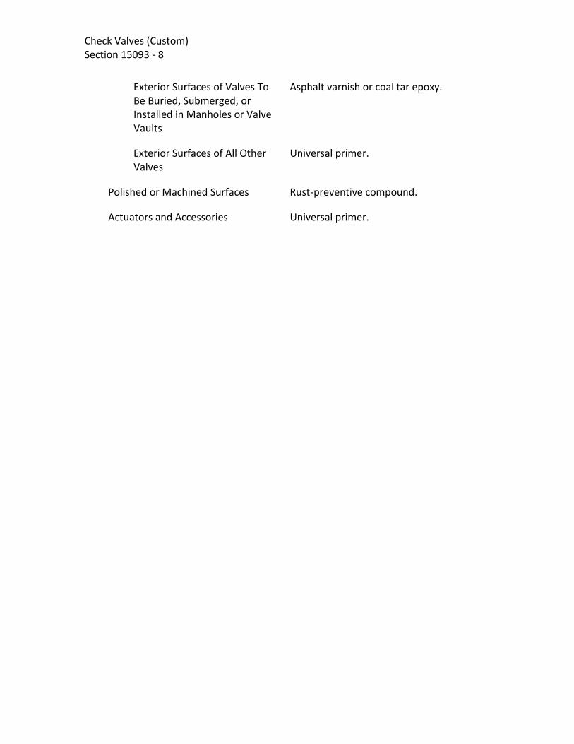
Check Valves (Custom) Section 15093 - 8
Exterior Surfaces of Valves To Be Buried, Submerged, or Installed in Manholes or Valve Vaults
Asphalt varnish or coal tar epoxy.
Exterior Surfaces of All Other Valves
Universal primer.
Polished or Machined Surfaces Rust-preventive compound.
Actuators and Accessories Universal primer.

Check Valves (Custom) Section 15093 - 9
PART 3 – EXECUTION 3-1. INSTALLATION. Materials furnished under this section shall be installed in
accordance with Valve Installation section.
3-2. VALVE SCHEDULE
Location Tag Number Size Type of Valve
Service Code(2)
Ends(1)
Contractor Supplied Valves
Forebay VCK-0055 24 VC-11 ROF F
Forebay VCK-0057 20 VC-11 RW F
Trasfer Pump Discharge – Perris I
VCK-1060 20 VC-11 ROF F
Transfer Pump Discharge VCK-1010 16 VC-11 ROF F
Transfer Pump Discharge VCK-1020 16 VC-11 ROF F
Transfer Pump Discharge VCK-1030 16 VC-11 ROF F
Transfer Pump Discharge VCK-1040 16 VC-11 ROF F
Forebay Influent – Duck Bill VCK-0105 16 VC-22 ROF C
Forebay Influent – Duck Bill VCK-0106 16 VC-22 ROF C
Forebay Influent – Duck Bill VCK-0107 16 VC-22 ROF C
Forebay Influent – Duck Bill VCK-0108 16 VC-22 ROF C
RO Cleaning to RO CIP Tank VCK-1625 10 VC-20 CIPCR F
Decarbonator 2 Influent – Transfer Pump Discharge
VCK-2041 16 VC-11 ROB F
Decarbonator 2 Influent – Forebay Bypass
VCK-2042 16 VC-11 ROB F
Finished Water Pump No. 1 VCK-2210 10 VC-8 FW F
Finished Water Pump No. 2 VCK-2220 10 VC-8 FW F

Check Valves (Custom) Section 15093 - 10
Location Tag Number Size Type of Valve
Service Code(2)
Ends(1)
Finished Water Pump No. 3 VCK-2230 14 VC-11 FW F
Finished Water Pump No. 4 VCK-2240 14 VC-11 FW F
Brine Pump No. 1 VCK-9115 12 VC-11 ROC F
Brine Pump No. 2 VCK-9125 12 VC-11 ROC F
Brine Pump No. 3 VCK-9135 12 VC-11 ROC F
ROSS Supplied Valves
RO Feed Pump No. 1 Discharge
VCK-1210 * VC-20 ROF F
RO Feed Pump No. 2 Discharge
VCK-1220 * VC-20 ROF F
RO Feed Pump No. 3 Discharge
VCK-1230 * VC-20 ROF F
ROU 1 Permeate VCK-1414 * VC-20 ROP F or L
ROU 1 CIP Permeate Return VCK-1415 * VC-20 CIPPR F or L
ROU 2 Permeate VCK-1424 * VC-20 ROP F or L
ROU 2 CIP Permeate Return VCK-1425 * VC-20 CIPPR F or L
ROU 3 Permeate VCK-1434 * VC-20 ROP F or L
ROU 3 CIP Permeate Return VCK-1435 * VC-20 CIPPR F or L
ROU 1 Concentrate VCK-1516 * VC-20 ROC F or L
ROU 2 Concentrate VCK-1526 * VC-20 ROC F or L
ROU 3 Concentrate VCK-1536 * VC-20 ROC F or L
CIP Pump 1 Discharge VCK-1610 * VC-20 CIP F or L
CIP Pump 2 Discharge VCK-1620 * VC-20 CIP F or L

Check Valves (Custom) Section 15093 - 11
Location Tag Number Size Type of Valve
Service Code(2)
Ends(1)
RO Flush Pump 1 Discharge VCK-1703 * VC-20 ROFL F or L
RO Flush Pump 2 Discharge VCK-1705 * VC-20 ROFL F or L
*Valve characteristics to be determined by equipment manufacturer in Shop Drawing Submittal. (1) Abbreviations for valve ends are as indicated:
C: 316 SS Clamp F: Flanged
L: Lugged MJ: Mechanical Joint
(2) See Instrumentation Drawings for service code definitions.
END OF SECTION

Check Valves (Custom) Section 15093 - 12
[PAGE INTENTIONALLY LEFT BLANK]

Backflow Preventers (Custom)
Section 15094 - 1
SECTION 15094
BACKFLOW PREVENTERS
PART 1 - GENERAL
1-1. SCOPE. This section covers the furnishing of backflow preventers and associated
appurtenances, as indicated herein.
Piping, pipe supports, insulation, and accessories which are not an integral part of the
backflow preventers or are not specified herein are covered in other sections.
1-2. GENERAL.
1-2.01. General Equipment Stipulations. The General Mechanical and Equipment
Provisions section shall apply to all equipment and materials provided under this
section. If requirements in this specification differ from those in the General Mechanical
and Equipment Provisions section, the requirements specified herein shall take
precedence.
1-2.02. Identification. Equipment specified herein shall be identified in accordance with
the Equipment and Valve Identification section.
1-3. SUBMITTALS.
1-3.01. Drawings and Data. Complete fabrication and assembly drawings, together with
detailed specifications and data covering materials, parts, devices, and accessories
forming a part of the equipment furnished, shall be submitted in accordance with the
Submittals Procedures section. The data and specifications for each unit shall include,
but shall not be limited to the following:
Name of manufacturer.
Type and model.
Construction materials and finishes.
Net weight.
Unit dimensions.
Performance curves indicating flow capacity versus pressure drop.
1-3.02. Operations and Maintenance Data and Manuals. Adequate operation and
maintenance information shall be supplied as required in the Submittals Procedures
section. Operation and maintenance manuals shall be submitted in accordance with the
Submittals Procedures section. The operation and maintenance manuals shall be in

Backflow Preventers (Custom)
Section 15094 - 2
addition to any instructions or parts lists packed with or attached to the equipment
when delivered.
1-4. DELIVERY, STORAGE, AND HANDLING. Shipping shall be in accordance with the
Product Delivery, Storage and Handling section.
PART 2 - PRODUCTS
2-1. PERFORMANCE AND DESIGN REQUIREMENTS. Backflow preventers shall be
designed to meet the requirements as indicated herein and in the Backflow Preventer
Schedule on the Drawings.
2-2. ACCEPTABLE MANUFACTURERS. Acceptable manufacturers and specific products
are listed in the Design and Construction paragraph.
2-3. DESIGN AND CONSTRUCTION. Backflow prevention device type shall be as
indicated herein.
2-3.01. Double Check Detector Assemblies (DCDA). Provide and install DCDA per
EMWD approved materials list and standard details.
2-3.02. Hose Connection Vacuum Breakers. Hose connection vacuum breakers shall be
provided with 3/4 inch [19 mm] hose thread ends, brass or bronze bodies, stainless steel
stem, rubber seat, and rubber disc. Hose connection vacuum breakers shall be of
tamper-resistant design to prevent removal, manual drain feature, and shall comply
with ASSE Standard 1011 requirements. Hose connection vacuum breakers shall be
Febco “Series 731”, Watts Regulator Company “Series 8” or Wilkins “Model BFP 8”.
PART 3 - EXECUTION
3-1. INSTALLATION. Materials furnished under this section will be installed in
accordance with the Valve Installation section.
END OF SECTION

Solenoid Valves (Custom) Section 15095 - 1
SECTION15095 SOLENOID VALVES
PART 1 - GENERAL 1-1. SCOPE. This section covers the furnishing of manually operated or remote activated two position (open-close) solenoid operated valves. Piping, pipe supports, insulation, and accessories that are not an integral part of the valves or are not specified herein are covered in other sections. 1-2. GENERAL. 1-2.01. General Equipment Stipulations. The General Mechanical and Equipment Provsions section shall apply to all equipment furnished under this section. If requirements in this specification differ from those in the General Mechanical and Equipment Provsions section, the requirements specified herein shall take precedence. 1-2.02. Identification. Valves specified herein shall be tagged in accordance with the Equipment and Valve Identification section. 1-3. SUBMITTALS. Complete drawings, details, and specifications covering the valves and their appurtenances shall be submitted in accordance with the General Conditions, Section F-29 Equipment and Material Items section. PART 2 - PRODUCTS 2-1. CONSTRUCTION. Solenoid valves shall have packless construction without packing box or sliding seal. Solenoid coils for AC service shall be 115volts, 60 hertz, encapsulated, Class F, for continuous duty at rated voltage ± 10 percent and 40°C ambient, in a NEMA Type 1 enclosure for indoor locations and Type 4 enclosure for outdoor locations, with a conduit knockout. Solenoid coils for DC service shall be 125 volts, Class H, for continuous duty at rated voltage ± 10 percent and 40°C ambient, in a NEMA Type 1 enclosure for indoor locations and Type 4 enclosure for outdoor locations, with a conduit knockout. Valves shall be normally closed unless otherwise specified or indicated on the drawings. Normally open solenoid valves shall close when energized and normally closed solenoid valves shall open when energized.

Solenoid Valves (Custom) Section 15095 - 2 2-1.01. Valves Type VSOL-1.
VSOL-1
Type Body/Bonnet Trim Seals Disc Stem Bonnet Gasket Spring End Connection Temp. Limitations Valve Operator Manufacturers
2-Way, pilot operated Brass or bronze Buna-N or Teflon Buna-N or Teflon Manufacturer’s standard Manufacturer’s standard Manufacturer’s standard Threaded 32 to 104°F [0 to 40°C] Integral ASCO “8210 Series”
2-1.02. Valves Type VSOL-2.
VSOL-2
Type Body/Bonnet Trim Seals Disc Stem Bonnet Gasket Spring End Connection Temp. Limitations Valve Operator Manufacturers
3-Way, pilot operated Brass or bronze Buna-N or Teflon Buna-N or Teflon Manufacturer’s standard Manufacturer’s standard Manufacturer’s standard Threaded 32 to 104°F [0 to 40°C] Integral ASCO “8316 Series”
2-1.03. Length Tolerance. Unless otherwise specified, the actual length of valves shall be within ± 1/16 inch [1.6 mm] of the specified or theoretical length. 2-1.04. Shop Coatings. All ferrous metal surfaces of valves and accessories, both interior and exterior, shall be shop coated for corrosion protection. The valve manufacturer’s standard coating will be acceptable, provided it is functionally equivalent to the specified coating.

Solenoid Valves (Custom) Section 15095 - 3
Coating Materials
Asphalt Varnish Fed Spec TT-C-494.
Coal Tar Epoxy High-build coal tar epoxy; Ameron "Amercoat 78HB Coal Tar Epoxy", Carboline "Bitumastic 300 M", Tnemec "46H-413 Hi-Build Tneme-Tar", or Sherwin-Williams "Hi-Mil Sher-Tar Epoxy".
Epoxy Enamel (for liquid service) Ameron "Amerlock 400 High-Solids Epoxy Coating", Carboline "Carboguard 891", or Tnemec "Series N140 Pota-Pox Plus".
Rust-Preventive Compound As recommended by the manufacturer.
Surfaces To Be Coated
Unfinished Surfaces
Interior Surfaces None
Exterior Surfaces of Valves To Be Buried, Submerged, or Installed in Manholes or Valve Vaults
Asphalt varnish or coal tar epoxy.
Exterior Surfaces of All Other Valves
Universal primer.
Polished or Machined Surfaces Rust-preventive compound.
2-2. ACCESSORIES. 2-2.01. Manual Operators. Valves shall be furnished with manual operators to allow valve operation when electrical power is off. PART 3 - EXECUTION 3-1. INSTALLATION. Materials furnished under this section shall be installed in accordance with the Valve Installation section.
END OF SECTION

Solenoid Valves (Custom) Section 15095 - 4
[PAGE LEFT INTENTIONALLY BLANK]

Globe Valves (Custom) Section 15096 - 1
SECTION 15096 GLOBE VALVES
PART 1 - GENERAL 1-1. SCOPE. This section covers the furnishing of manually operated or remote activated two position (open-close) globe valves for RO System service as specified herein and as indicated in the Globe Valve Schedule. 1-2. GENERAL. Equipment furnished under this section shall be fabricated and assembled in full conformity with drawings, specifications, engineering data, instructions, and recommendations of the equipment manufacturer unless exceptions are noted by Engineer. Valves shall be furnished with all necessary parts and accessories indicated on the drawings, specified, otherwise required for a complete, properly operating installation and shall be the latest standard products of a manufacturer regularly engaged in the production of valves. Valves furnished under this section shall tolerate the water quality as described in the section 13025 Low Pressure RO System. 1-2.01. General Equipment Stipulations. The General Mechanical and Equipment provisions section shall apply to all equipment furnished under this section. If requirements in this specification differ from those in the General Mechanical and Equipment provisions section, the requirements specified herein shall take precedence. 1-2.02. Coordination. All equipment provided under this section shall be furnished by or through a single manufacturer who shall be responsible for the design, coordination, and satisfactory performance of all components over the full operating range. 1-2.03. Tagging. Each item of equipment and each part shipped separately shall be tagged and identified with indelible markings for the intended service. Tag number shall be clearly marked on all shipping labels and on the outside of all containers. 1-2.04. Identification. Valves specified herein shall be tagged in accordance with the Equipment and Valve Identification section. 1-3. SUBMITTALS. Complete drawings, details, and specifications covering the valves and their appurtenances shall be submitted in accordance with the General Conditions, Section F-29 Equipment and Material section. Included in the submittal shall be drawings by the valve manufacturer to indicate the position of the valve actuator and valve shaft.

Globe Valves (Custom) Section 15096 - 2
PART 2 - PRODUCTS 2-1. CONSTRUCTION. 2-1.1 Valves VGL-1.
VGL-13
RO Train Reject Control
Rating Type Body/Bonnet Trim Plug Seat Ring Cage Stem Packing End Connection Temp. Limitations Valve Operator Manufacturers
Class 150 High performance cage-guided globe valve with one stage anti-cavitation trim Type 2205 Duplex stainless steel Heat treated Type 420 stainless steel 17-4 PH stainless steel 17-4 PH stainless steel PTFE Flanged, ASME B16.1, Class 300 0 to 350°F Electric as specified in Valve and Gate Actuators section Fisher “Design ET”, Masoneilan “41005” Series
2-1.2. Length Tolerance. Unless otherwise specified, the actual length of valves shall be within plus or minus 1/16 inch [1.6 mm] of the specified or theoretical length. 2-1.3. Shop Coatings. All ferrous metal surfaces of valves and accessories, both interior and exterior, shall be shop coated for corrosion protection. The valve manufacturer’s standard coating will be acceptable, provided it is functionally equivalent to the specified coating.
Coating Materials
Asphalt Varnish Fed Spec TT-C-494.
Coal Tar Epoxy High-build coal tar epoxy; Ameron "Amercoat 78HB Coal Tar Epoxy", Carboline "Bitumastic 300 M", Tnemec "46H-413 Hi-Build Tneme-Tar", or Sherwin-Williams "Hi-Mil Sher-Tar Epoxy".
Epoxy Enamel (for liquid service) Ameron "Amerlock 400 High-Solids Epoxy

Globe Valves (Custom) Section 15096 - 3
Coating", Carboline "Carboguard 891", or Tnemec "Series N140 Pota-Pox Plus".
Rust-Preventive Compound As recommended by the manufacturer.
Surfaces To Be Coated
Unfinished Surfaces
Interior Surfaces
Liquid Service Asphalt varnish (two coats) or epoxy enamel.
Exterior Surfaces of Valves To Be Buried, Submerged, or Installed in Manholes or Valve Vaults
Asphalt varnish or coal tar epoxy.
Exterior Surfaces of All Other Valves
Universal primer.
Polished or Machined Surfaces Rust-preventive compound.
Actuators and Accessories Universal primer.
2-2. VALVE ACTUATORS. Unless otherwise specified, globe valves shall be provided with handweel type manual actuators. Handwheel diameter shall be manufacturers standard size. Unless otherwise specified, valves indicated to be electric motor operated on the drawings shall have reversible electric motor operators designed for 120 volt ac, single phase operation. Actuators shall include integral thermal overload protection and a declutchable manual override. Actuators shall be equipped with motor operation limit switches and two additional single-pole, double-throw limit switches for auxiliary open and closed indication. An internal heater and thermostat shall be provided in each actuator housing to prevent condensation. Actuators in Class I, Division 1 or Division 2, Group D hazardous areas indicated on the drawings shall have NEMA Type 7 housings. Actuators in other areas shall have NEMA Type 4X housings. 2-3. ACCESSORIES. Requirements for extension stems and stem guides; position indicators; floor boxes; valve boxes; and operating stands shall be as specified in Valve and Gate Actuators section.

Globe Valves (Custom) Section 15096 - 4
PART 3 - EXECUTION 3-1. INSTALLATION. Materials furnished under this section shall be installed in accordance with Valve Installation section. 3-2. VALVE SCHEDULE
Performance and Design Requirements
Valve Tag Number VGL-1513 VGL-1523 VGL-1533
Location RO Concentrate Unit 1
RO Concentrate Unit 2
RO Concentrate Unit 3
Type of Service (1) RO Concentrate
RO Concentrate
RO Concentrate
Diameter (in) 8* 8* 8*
Type (2) PO PO PO
Maximum Inlet Pressure (Remark 1), psig
* * *
Minimum Inlet Pressure (Remark 1), psig
* * *
Flow Control Range, gpm * * *
Ordinary Flow Rate, gpm
gpm
Required Downstream Pressure (psi)
10 10 10
Remarks:
* To be determined by RO System Supplier
END OF SECTION

Pinch and Diaphragm Valves (Custom) Section 15097 - 1
SECTION 15097 PINCH AND DIAPHRAGM VALVES
PART 1 – GENERAL 1-1. SCOPE. This section covers the furnishing of manually operated or remote activated two position (open-close) or modulating pinch and diaphragm valves. Piping, pipe supports, insulation, and accessories that are not an integral part of the valves or are not specified herein are covered in other sections. Valve actuators are covered in the Valve and Gate Actuator section. 1-2. GENERAL. 1-2.01. General Equipment Stipulations. The General Mechanical and Equipment Provisions section shall apply to all equipment furnished under this section. If requirements in this specification differ from those in the General Mechanical and Equipment Provisions section, the requirements specified herein shall take precedence. 1-2.02. Identification. Valves specified herein shall be tagged in accordance with the Equipment and Valve Identification section. 1-3. SUBMITTALS. Complete drawings, details, and specifications covering the valves and their appurtenances shall be submitted in accordance with the General Conditions, Section F-29 Equipment and Material section. PART 2 - PRODUCTS 2-1. PINCH VALVE CONSTRUCTION. 2-1.01. Valves VPN-1. Pinch valves shall consist of the valve body, elastomer sleeve
liner, pinch bars, pull bars, actuator shaft, actuator base plate or yoke, actuator and assembly hardware. The valves shall be opened and closed with two mechanical pinch bars that constrict the elastomer sleeve liner between the bars. The pinch bars shall be enclosed inside the valve body. The top pinch bar shall be raised and lowered by a center actuator shaft. The lower pinch bar shall be raised and lowered with two pull bars anchored to the actuator base plate or yoke.
Valves shall provide 100 percent of the port area of the joining pipe at the valve ends and, unless otherwise specified, through the entire length of the valve. Valves shall be capable of closing bubble tight against the maximum line pressure. 2-1.02. Valve Body. Pinch valves shall be enclosed, split body design. All valves shall

Pinch and Diaphragm Valves (Custom) Section 15097 - 2 have flanged ends compatible with connecting piping. Flange diameter and drilling shall conform to ANSI B16.1, Class 125. Flanges shall be finished to true plane surfaces within a tolerance limit of 0.005 inch. The finished face shall be normal to the longitudinal valve axis within a maximum angular variation tolerance of 0.002 inch per foot of flange diameter. 2-1.03. Elastomer Sleeve Liner. Pinch valves shall be equipped with a one piece, seamless flange-to-flange elastomer sleeve liner specifically designed for the specified service conditions. The elastomer sleeve shall be compression molded or hand wrapped and reinforced with polyester cord ply. Pull tabs attached to the cord ply and extending through the exterior elastomer coating shall be furnished for attachment to the pinch bars to ensure positive opening force under negative pipeline pressure.
VPN-1
Where indicated by the Drawings
Rating Body Trim Elastomer Sleeve Liner Pull and Pinch Bars Stem and Guide Rods Assembly Hardware End Connection Valve Operator Temp. Limitations Pressure Limitations 6 inch and smaller 8 and 12 inch 14 inch and larger Manufacturers
Class 125 Cast iron, ASTM A48 Buna-N with polyester reinforcing cord ply Ductile iron or carbon steel when enclosed. Stainless steel, AISI Type 316 when exposed. Stainless steel, AISI Type 316 Stainless steel, AISI Type 316 Flanged, ASME B16.1, Class 125, flat faced Manual with handwheel 40 to 225°F [4 to 107°C] 150 psig [1.0 MPa] 100 psig [690 kPa] 50 psig [345 kPa] Onyx Valve Co. “Model DHC”, RF Technologies, Inc. “RF Valve”, or Red Valve, “Series 75”, RKL Moyno Inc., or Flexible Valve Co.
2-1.04. Length Tolerance. Unless otherwise specified, the actual length of valves shall be within plus or minus 1/16 inch [1.6 mm] of the specified or theoretical length. 2-1.05. Shop Coatings. All ferrous metal surfaces of valves and accessories, both interior and exterior, shall be shop coated for corrosion protection. The valve manufacturer’s standard coating will be acceptable, provided it is functionally equivalent to the specified coating.

Pinch and Diaphragm Valves (Custom) Section 15097 - 3
Coating Materials
Asphalt Varnish Fed Spec TT-C-494.
Coal Tar Epoxy High-build coal tar epoxy; Ameron "Amercoat 78HB Coal Tar Epoxy", Carboline "Bitumastic 300 M", Tnemec "46H-413 Hi-Build Tneme-Tar", or Sherwin-Williams "Hi-Mil Sher-Tar Epoxy".
Epoxy Enamel (for liquid service) Ameron "Amerlock 400 High-Solids Epoxy Coating", Carboline "Carboguard°891", or Tnemec "Series N140 Pota-Pox Plus".
Rust-Preventive Compound As recommended by the manufacturer.
Surfaces To Be Coated
Unfinished Surfaces
Interior Surfaces
Liquid Service Epoxy enamel.
Exterior Surfaces of Valves To Be Buried, Submerged, or Installed in Manholes or Valve Vaults
Asphalt varnish or coal tar epoxy.
Exterior Surfaces of All Other Valves
Universal primer.
Polished or Machined Surfaces Rust-preventive compound.
Actuators and Accessories Universal primer.
2-2. DIAPHRAGM VALVE CONSTRUCTION. 2-2.01. Valves VD-1. Diaphragm valves used in sodium hypochlorite service shall be provided with socket weld ends. Flanged ends may be used where required to facilitate disassembly of piping or equipment, or where acceptable to the Engineer.
VD-1
Where indicated by the Drawings
Rating Body Trim Diaphragm
Class 150 CPVC Two-piece unbonded, Teflon and EPDM Socket weld, flanged, ASME B16.1, Class

Pinch and Diaphragm Valves (Custom) Section 15097 - 4
End Connection Operator Manufacturers
125, flat faced Handwheel with travel-stop & position indicator Asahi/America “Type G”, “Type 14 Diaphragm Valves”, or “Type 15 Diaphragm Valves”, ITT “Dia-Flo Valves”
2-3. VALVE ACTUATORS. Manual actuated valves shall be provided with handwheels as specified herein. Requirements for automatic valve actuators shall be as specified herein and as specified in the Valve and Gate Actuators section. 2-3.01. Manual Actuators. Manual actuators of the types listed hereinshall be provided by the valve manufacturer. Unless otherwise indicated or specified, each geared manual actuator shall be equipped with an operating handwheel. The direction of rotation of the wheel to open the valve shall be to the left (counterclockwise). Each valve body or actuator shall have cast thereon the word "Open" and an arrow indicating the direction to open. The housing of traveling-nut type actuators shall be fitted with a removable cover which shall permit inspection and maintenance of the operating mechanism without removing the actuator from the valve. Travel limiting devices shall be provided inside the actuator for the open and closed positions. Travel limiting stop nuts or collars installed on the reach rod of traveling-nut type operating mechanisms shall be field adjustable and shall be locked in position by means of a removable roll pin, cotter pin, or other positive locking device. The use of stop nuts or adjustable shaft collars which rely on clamping force or setscrews to prevent rotation of the nut or collar on the reach rod will not be acceptable. Each actuator shall be designed so that shaft seal leakage cannot enter the actuator housing. Valves for throttling service shall be equipped with an infinitely variable locking device or a totally enclosed gear actuator. Actuators shall produce the required torque with a maximum pull of 80 lbs [356 N] on the lever, handwheel, or chain. Actuator components shall withstand, without damage, a pull of 200 lbs [890 N] on the handwheel or chainwheel or an input of 300 foot-lbs [407 J] on the operating nut. 2-3.02. Handwheels. Not used.

Pinch and Diaphragm Valves (Custom) Section 15097 - 5
2-3.03. Chainwheels. Unless otherwise specified in the valve schedules, all valves with center lines more than 7'-6" [2.3 m] above the floor shall be provided with chainwheels and operating chains. Each chainwheel operated valve shall be equipped with a chain guide which will permit rapid handling of the operating chain without "gagging" of the wheel and will also permit reasonable side pull on the chain. Suitable extensions shall be provided, if necessary, to prevent interference of the chain with adjacent piping or equipment. Operating chains shall be hot-dip galvanized carbon steel and shall be looped to extend to within 4 feet [1.2 m] of the floor below the valve. 2-4. ACCESSORIES. Requirements for extension stems and stem guides, position indicators, floor boxes, operating stands, torque tubes, and valve boxes shall be as specified in the Valve and Gate Actuators section. PART 3 - EXECUTION 3-1. INSTALLATION. Materials furnished under this section shall be installed in accordance with the Valve Installation section.
END OF SECTION

Pinch and Diaphragm Valves (Custom) Section 15097 - 6
[PAGE LEFT INTENTIONALLY BLANK]

Miscellaneous Plug Valves (Custom) Section 15098 - 1
SECTION 15098 MISCELLANEOUS PLUG VALVES
PART 1 - GENERAL 1-1. SCOPE. This section covers the furnishing of manually operated or remote activated two position (open-close) plug valves. Piping, pipe supports, insulation, and accessories that are not an integral part of the valves or are not specified herein are covered in other sections. Valve actuators are covered in the Valve and Gate Actuator section. 1-2. GENERAL. 1-2.01. General Equipment Stipulations. The General Mechanical and Equipment Provisions section shall apply to all equipment furnished under this section. If requirements in this specification differ from those in the General Mechanical and Equipment Provisions section, the requirements specified herein shall take precedence. 1-2.02. Identification. Valves specified herein shall be tagged in accordance with the Equipment and Valve Identification section. 1-3. SUBMITTALS. Complete drawings, details, and specifications covering the valves and their appurtenances shall be submitted in accordance with the General Conditions, Section F-29 Equipment and Material Items section . Included in the submittal shall be drawings by the valve manufacturer to indicate the position of the valve actuator and valve shaft. Submittal drawings shall clearly indicate the country of origin of all cast gray iron and ductile iron valve components. PART 2 - PRODUCTS 2-1. CONSTRUCTION. 2-1.01. Valves VP-1. Not used. 2-1.02. Valves VP-2. Not used.

Plug Valves (Custom) Section 15098 - 2 2-1.03. Valves VP-3.
VP-3
Sodium hydroxide
service
Rating Type Body Trim Plug Seal Plug Seal Diaphragm End Connection Temp. Limitations Valve Operator Manufacturers
Class 150 Non-lubricated, tapered plug valve Carbon steel Teflon 316 stainless steel Teflon Socket Weld or Flanged -20 to 200°F Lever Dezurik “PPS”, Flowserve/Durco “G414-DSD4” or “G411-DSD4”
2-1.04. Length Tolerance. Unless otherwise specified, the actual length of valves shall be within plus or minus 1/16 inch [1.6 mm] of the specified or theoretical length. 2-1.05. Shop Coatings. All ferrous metal surfaces of valves and accessories, both interior and exterior, shall be shop coated for corrosion protection. The valve manufacturer’s standard coating will be acceptable, provided it is functionally equivalent to the specified coating.
Coating Materials
Coal Tar Epoxy High-build coal tar epoxy; Ameron "Amercoat 78HB Coal Tar Epoxy", Carboline "Bitumastic 300 M", Tnemec "46H-413 Hi-Build Tneme-Tar", or Sherwin-Williams "Hi-Mil Sher-Tar Epoxy".
Epoxy Enamel Ameron "Amercoat 385 Epoxy", Carboline "Carboguard 890", or Tnemec "Series N69 Hi-Build Epoxoline II".
Rust-Preventive Compound As recommended by the manufacturer.
Surfaces To Be Coated
Unfinished Surfaces
Interior Surfaces Epoxy.
Exterior Surfaces of Valves To Be Buried, Submerged, or Installed in Manholes or Valve
Coal tar epoxy.

Miscellaneous Plug Valves (Custom) Section 15098 - 3
Vaults
Exterior Surfaces of All Other Valves
Universal primer.
Polished or Machined Surfaces Rust-preventive compound.
Actuators and Accessories Universal primer.
2-2. VALVE ACTUATORS. Requirements for valve actuators shall be as specified in the Valve and Gate Actuators section. 2-3. ACCESSORIES. Requirements for extension stems and stem guides, position indicators, floor boxes, operating stands, and valves boxes shall be as specified in Valve and Gate Actuators section. PART 3 - EXECUTION 3-1. INSTALLATION. Materials furnished under this section shall be installed in accordance with the Valve Installation section.
END OF SECTION

Plug Valves (Custom) Section 15098 - 4
[PAGE LEFT INTENTIONALLY BLANK]

Pressure Reducing Valves (Custom) Section 15099 - 1
SECTION 15099
PRESSURE REDUCING VALVES PART 1 - GENERAL 1-1. SCOPE. This section covers the furnishing of pressure reducing valves as specified herein. Piping, pipe supports, insulation, and accessories which are not an integral part of the valves or are not specified herein are covered in other sections. 1-2. GENERAL.
1-2.01. General Equipment Stipulations. The General Mechanical and Equipment Provisions section shall apply to all equipment and materials provided under this section. If requirements in this specification differ from those in the General Mechanical and Equipment Provisions section, the requirements specified herein shall take precedence. 1-2.02. Identification. Valves specified herein shall be identified in accordance with the Equipment and Valve Identification section. 1-3. SUBMITTALS. 1-3.01. Drawings and Data. Complete fabrication and assembly drawings, together with detailed specifications and data covering materials, parts, devices, and accessories forming a part of the equipment furnished, shall be submitted in accordance with the General Conditions, Section F-29 Equipment and Material Items section. The data and specifications for each unit shall include, but shall not be limited to, the following:
Name of manufacturer.
Type and model.
Construction materials and finishes.
Unit dimensions.
Performance curves indicating flow capacity versus pressure drop.
1-3.02. Operation and Maintenance Data and Manuals. Operation and maintenance manuals shall be submitted in accordance with the Maintenace Manual Requirements section, in the District's General Conditions, Section 01430, and as specified herein. The operation and maintenance manuals shall be in addition to any instructions or parts lists packed with or attached to the equipment when delivered.

Pressure Reducing Valves Section 15099 - 2 PART 2 - PRODUCTS 2-1. PERFORMANCE AND DESIGN REQUIREMENTS. Pressure reducing valves shall be designed to meet the service requirements as indicated herein and in the Pressure Reducing Valves Schedule on the Drawings. Each pressure reducing valve shall be designed to provide tight shutoff under conditions of no flow and shall not "hunt" under ordinary flow conditions. Pressure reducing valves shall be selected and sized as recommended by the valve manufacturer. Valve pressure setpoint shall be adjustable to at least 20 percent above and below the reduced pressure setpoint. Valves furnished under this section shall tolerate the water quality as described in the section 13025 Low Pressure RO System.
2-2. ACCEPTABLE MANUFACTURERS. Acceptable manufacturers and specific products are listed in the Construction paragraph. 2-3. MATERIALS. Valve materials shall be as indicated below and in the Construction paragraph.
Shop Coatings
Epoxy Enamel, NSF certified (Liquid Service)
Ameron "Amerlock 400 High-Solids Epoxy Coating", Carboline "Carboguard 891", or Tnemec "Series N140 Pota-Pox Plus"; immersion service.
Epoxy Enamel (Gas and Air Service)
Ameron "Amercoat 385 Epoxy", Carboline "Carboguard 890", or Tnemec "Series N69 Hi-Build Epoxoline II".
Other As recommended per Manufacturer 2-4. CONSTRUCTION. Water Pressure reducing valves for water service shall be direct-acting or pilot-operated type as indicated in the Pressure Reducing Valve Schedule. 2-4.01. Direct Acting Pressure Reducing Valve. Direct-acting valves shall be globe type with threaded connections and union assembly. The valves shall be provided with bronze body and cover, stainless steel trim, reinforced neoprene diaphragm, Buna-N disc, and stainless steel strainer. Direct-acting pressure reducing valves shall be Cla-Val “Model CRD-L”, Singer, Cash-Acme, or Watts. 2-4.01. Pilot-Operated Pressure Reducing Valves 2-4.01.1. Pressure Reducing Valve.

Pressure Reducing Valves (Custom) Section 15099 - 3
A. Hydraulically operated, single diaphragm-actuated, globe valve.
B. Pilot-Controlled: 1. Direct acting. 2. Adjustable. 3. Spring loaded. 4. Normally Open. 5. Diaphragm valve.
C. The valve shall be hydraulically operated, single diaphragm-actuated, globe pattern. Valve shall consist of three major components: the body, with seat installed; the cover, with bearings installed; and the diaphragm assembly. The diaphragm assembly shall be the only moving part and shall form a sealed chamber in the upper portion of the valve, separating operating pressure from line pressure.
D. Pressure Reducing Operation: The Pressure Reducing Valve shall maintain a constant downstream pressure regardless of changing flow rate and/or varying inlet pressure. The pressure reducing pilot control shall be a direct-acting, adjustable, spring-loaded, normally open, diaphragm valve designed to permit flow when controlled pressure is less than the spring setting. The pilot control system shall include a fixed orifice, opening speed control, shutoff cocks and strainer.
E. Opening Speed Control: Flow control the opening speed of the main valve.
F. Isolation Valves: Ball valve used to isolate the pilot system from the main line pressure.
G. Closing Speed Control: Flow control the closing speed of the main valve.
H. Fixed orifice.
I. Pilot strainer.
J. Single removable stainless steel one-piece seat: capable of being completely serviced and repaired while installed.
K. Class 150: Pressure rating 250 psi.
L. Components: 1. Body and cover:
a. Manufactured of Ductile Iron conforming to the requirements of ASTM A-536.

Pressure Reducing Valves Section 15099 - 4
b. Label: Raised letters on the case for manufacturer, valve size, model number, and arrows indicating the direction of flow.
c. Internal metallic parts: ASTM A240 Type 303 stainless steel. d. Control tube and fittings: ASTM A240 Type 304 or 316 stainless
steel. e. Pilot valve disc retainer assembly: ASTM A240 Type 304 or 316
stainless steel. f. Casing bolts and nuts: Cadmium-plated steel or ASTM A240
Type 304 or 316 stainless steel. g. Rubber Material: Buna “N”. h. Available spring ranges: 0 to 600 psi. i. Valve Position Indicator. j. Stainless Steel Liquid Filled Pressure Gauges. Installed on inlet
and outlet of the valve.
M. Provide Pilot System with Following: 1. Pressure Rating: 300 psi. 2. Body and Cover: Bronze ASTM B-62. 3. Trim: Stainless Steel 4. Rubber Material: Buna “N”. 5. Tubing and Fittings: Stainless Steel 6. Pressure Relief Adjustment: Range: 20-200 psi 7. Strainer: Stainless Steel 316 screen and body “Y” strainer. 8. Ball valve at valve inlet, cover and outlet.
N. Coating: Fusion bonded epoxy, nominal DFT 5-7 mils, in accordance with Section 09900.
O. Insulation: 1. Provide minimum 1 inch urethane foam insulation. 2. Provide aluminum sheath covering over urethane insulation, seal with
aluminum tape and secure with aluminum banding.
P. Manufactured by: 1. Cla-Val Company, 90- Series 2. Singer Valve, 106-PR Series
2-4.01.1Pressure Relief / Pressure Sustaining Valve
A. Hydraulically operated, single diaphragm-actuated, globe valve.
B. Pilot-Controlled: 1. Direct acting. 2. Adjustable.

Pressure Reducing Valves (Custom) Section 15099 - 5
3. Spring loaded. 4. Diaphragm valve.
C. Valve shall consist of the following: body with seat installed, the cover with bearing installed, and the diaphragm assembly. Valve shall be designed for extreme differential pressures. The internal anti-cavitation trim shall dissipate flow harmlessly, eliminating noise and damage to the main valve without the aid of orifice plates or other devices external to the main valve.
D. Functionality: It shall contain a resilient, Buna "N" synthetic rubber disc, forming a tight seal against a single removable seat insert. The diaphragm assembly containing a rifled slotted 303 stainless steel valve or oxy-nitride coated stem shall be fully guided at both ends by a bearing in the valve cover and an integral bearing in the valve seat. Additionally, it shall be the only moving part and shall form a sealed chamber in the upper portion of the valve, separating operating pressure from line pressure.
E. Pressure Relief Operation: As recommended by manufacturer. Is normally open control that senses main valve outlet pressure changes. An increase in outlet pressure tends to close control and a decrease in outlet pressure tends to open control. This causes the main valve cover pressure to vary and the main valve modulates (opens and closes) maintaining a relatively constant outlet pressure.
F. Pressure Sustaining Operation: Provide minimum pressure during pump start-up and maintain required upstream pressure.
G. Anti-cavitation seat main valve seat guides
H. Single removable stainless steel one-piece seat: capable of being completely serviced and repaired while installed.
I. Class 150: Pressure rating 250 psi.
J. Components: 1. Body and cover:
a. Manufactured of Ductile Iron conforming to the requirements of ASTM A-536.
b. Label: Raised letters on the case for manufacturer, valve size, model number, and arrows indicating the direction of flow.
c. Main Valve Trim: 316 Stainless Steel d. Control tube and fittings: ASTM A240 Type 304 or 316 stainless
steel. e. Casing bolts and nuts: Cadmium-plated steel or ASTM A240
Type 304 or 316 stainless steel.

Pressure Reducing Valves Section 15099 - 6
f. Rubber Material: Buna “N”. g. Available spring ranges: 0 to 600 psi. h. Valve Position Indicator. i. Stainless Steel Liquid Filled Pressure Gauges. Installed on inlet of
the valve.
K. Provide Pilot System with Following: 1. Pressure Rating: 300 psi. 2. Body and Cover: Bronze ASTM B-62. 3. Trim: Stainless Steel 4. Rubber Material: Buna “N”. 5. Tubing and Fittings: Stainless Steel 6. Pressure Relief Adjustment: Range: 2-120 psi 7. Strainer: Stainless Steel 316 screen and body “Y” strainer. 8. Ball valve at valve inlet, cover and outlet.
L. Coating: Fusion bonded epoxy, nominal DFT 5-7 mils, in accordance with Section 09900.
M. Insulation: 1. Provide minimum 1 inch urethane foam insulation for pilot piping. 2. Provide aluminum sheath covering over urethane insulation, seal with
aluminum tape and secure with aluminum banding.
N. Manufactured by: 1. Cla-Val Company, Model 50-01BPVKCKOKD. 2. SingerValve, 106-RPS-AC series.
2-5. SHOP PAINTING. All ferrous metal surfaces of valves and accessories, both interior and exterior, shall be shop painted for corrosion protection in accordance with the following list. The valve manufacturer’s standard coating will be acceptable, provided it is functionally equivalent to the specified coating and is compatible with the field painting specified in the Protective Coatings section.
Interior Surfaces
Liquid Service Epoxy (NSF certified). Gas and Air Service Epoxy. Exterior Surfaces Universal primer with epoxy finish coat.
PART 3 - EXECUTION 3-1. INSTALLATION. Materials furnished under this section will be installed in accordance with the Valve Installation section.

Pressure Reducing Valves (Custom) Section 15099 - 7
3-2. PRESSURE REDUCING VALVE SCHEDULE
Performance and Design Requirements
Valve Tag Number VPC-2100 VPC-1010 VPC-2101
Location Finished Water PS Purge
Transfer Pump Recirculation
Finished Water Injection Point
Type of Service (1) W W W
Valves Ends Flanged Flanged Flanged
Type (2) PO PO DO
Diameter 10” 6” 2”
Maximum Inlet Pressure (psig) 104 97 104
Minimum Inlet Pressure (psig) 101 75 101
Reduced Pressure Setting (psig) 71 to 96 80 - 97 40 to 43
Maximum Flow (3) (gpm) 3,125 500 80
Ordinary Flow (gpm) 1,563 500 80
Minimum Controlled Flow (gpm) 1,563 500 80
Minimum Permissible Pressure at Maximum Flow (psig)
10 0.5 61
Remarks
Notes: (1) Abbreviations for types of service are as follows:
W Water
(2) Abbreviations for pressure reducing valve type are as follows:
DO Direct-operated PO Pilot-operated POL Pilot-operated with low flow bypass
(3) Units of flow are as follows:

Pressure Reducing Valves Section 15099 - 8
Water service gallons per minute (gpm)
END OF SECTION

Miscellaneous Valves Section 15100 - 1
SECTION 15100 MISCELLANEOUS VALVES
PART 1 - GENERAL 1-1. SCOPE. This section covers the furnishing of miscellaneous valves as specified herein, except where specific requirements are stipulated in other sections. 1-2. GENERAL. 1-2.01. General Equipment Stipulations. The General Mechanical and Equipment Provisions section shall apply to all equipment furnished under this section. If requirements in this specification differ from those in the General Mechanical and Equipment Provisions section, the requirements specified herein shall take precedence. 1-2.02. Identification. Valves specified herein shall be tagged in accordance with the Equipment and Valve Identification section. 1-3. SUBMITTALS. Complete drawings, details, and specifications, covering the valves and their appurtenances shall be submitted in accordance with the General Conditions, Section F-29 Equipment and Material section. Included in the submittal shall be drawings by the valve manufacturer to indicate the position of the valve actuator and valve shaft. PART 2 - PRODUCTS 2-1. CONSTRUCTION. 2-1.01. Length Tolerance. Unless otherwise specified, the actual length of valves shall be within ±1/16 inch [1.6 mm] of the specified or theoretical length. 2-1.02. Shop Coatings. All ferrous metal surfaces of valves and accessories, both interior and exterior, shall be shop coated for corrosion protection. The valve manufacturer’s standard coating will be acceptable, provided it is functionally equivalent to the specified coating.

Miscellaneous Valves Section 15100 - 2
Coating Materials
Epoxy (for liquid service) PPG Amercoat "Amerlock 400 High-Solids Epoxy Coating", Carboline "Carboguard 891", Sherwin-Williams “Macropoxy 646NSF”or Tnemec "Series N140 Pota-Pox Plus".
Rust-Preventive Compound As recommended by the manufacturer.
Surfaces To Be Coated
Unfinished Surfaces
Interior Surfaces
Liquid Service Epoxy enamel.
Exterior Surfaces of Valves to be Buried, Submerged, or Installed in Manholes or Valve Vaults
Epoxy.
Exterior Surfaces of all Other Valves
Universal primer.
Polished or Machined Surfaces Rust-preventive compound.
Actuators and Accessories Universal primer.
2-2. HOSE FAUCETS, HYDRANTS, AND CURB STOPS. 2-2.01. Hose Faucets, VHF-1.
VHF-1
Hose faucet
Type Body/Bonnet Trim
Seat Disc Stem Stem Seal
End Connection Temp. Limitations Valve Operator Manufacturers
Faucet, threaded bonnet. Brass. Manufacturer’s standard. Manufacturer’s standard. Manufacturer’s standard. Manufacturer’s standard. Threaded, male NPT x male HPT. 32°F to 212°F [0°C to 100°C]. T-handle. Prier Brass "C - 138NP.75" or Dearborn Brass.

Miscellaneous Valves Section 15100 - 3
2-2.02. Wall Hydrants, VHF-2. .
VHF-2
Wall hydrant
Type Body/Bonnet Trim
Seat Disc Stem Stem Seal
End Connection Temp. Limitations Valve Operator Manufacturers
Freezeproof. Brass or bronze. Manufacturer’s standard. Manufacturer’s standard. Manufacturer’s standard. Manufacturer’s standard. Threaded, NPT x male HPT. 32°F to 212°F [0°C to 100°C]. Removable key. Smith "5609", Wade " 8600", Woodford "60", or Zurn "Z-1315".
2-2.03. Wall Hydrants with Vacuum Breaker, VHF-3.
VHF-3
Wall hydrants with vacuum
breaker
Type Body Trim
Seat Disc Stem Stem Seal
End Connection Temp. Limitations Valve Operator Manufacturers
Freezeproof, with vacuum breaker. Brass or bronze. Manufacturer’s standard. Manufacturer’s standard. Manufacturer’s standard. Manufacturer’s standard. Threaded, NPT x male HPT. 32°F to 212°F [0°C to 100°C]. Removable key. Smith "5609", or Wade " 8600".
2-2.04. Post Type Yard Hydrants, VHF-4.
VHF-4
Post type yard hydrant
Type Body Trim
Seat Disc Stem Stem Seal
End Connection Temp. Limitations Valve Operator Manufacturers
Nonfreeze, post type. Brass or bronze. Manufacturer’s standard. Manufacturer’s standard. Manufacturer’s standard. Manufacturer’s standard. Threaded, NPT x HPT. 32°F to 212°F [0°C to 100°C]. Removable key. Smith "5910/5914", Wade "8610", or Zurn "Z-1385/1390".

Miscellaneous Valves Section 15100 - 4 2-2.05. Curb Stops, VCS-1.
VCS-1
Curb stop
Code Type Body Trim
Seat Plug/Ball Stem Stem Seal
End Connection Temp. Limitations Valve Operator Manufacturers
ANSI/AWWA C800. Straight-through. Brass or bronze. Manufacturer's standard. Manufacturer's standard. Manufacturer's standard. Manufacturer's standard. Threaded. 32°F to 212°F [0°C to 100°C]. T-handle. Ford Meter Box "Ford Ball Valve", Hays "Nuseal Curb Stop", or Mueller "Mark II Oriseal".
2-2.06. Fire Hydrants. Fire hydrants shall conform to ANSI/AWWA C502 and local jurisdictional requirements. Refer to EMWD standard details and Approved Materials List. 2-3. VALVE ACTUATORS. Requirements for valve actuators shall be as specified in the Valve and Gate Actuator section. 2-4. ACCESSORIES. When the Drawings indicate the need for extension stems; position indicator; floor boxes; or operating stands, refer to the Valve and Gate Actuator section. 2-5.01. Valve Boxes. Each valve buried to a depth of 4 feet [1.2 m] or less shall be provided with a slide type valve box. Valve boxes shall be cast iron, extension sleeve type, suitable for the depth of cover indicated on the Drawings. Only one extension will be allowed with each slide type valve box. Valve boxes shall be at least 5 inches [125 mm] in inside diameter, shall be at least 3/16 inch [4.7 mm] thick, and shall be provided with suitable cast iron bases and covers. Each valve buried deeper than 4 feet [1.2 m] shall be provided with a valve box consisting of a cast iron cover and base, and a 6 inch [150 mm] cast iron pipe section. The cover and base shall be Clay & Bailey "No. 2193NS". The pipe shaft shall extend from the valve to 5 inches [125 mm] inside the valve box base. All parts of valve boxes, bases, and covers shall be shop coated with the manufacturer’s standard coating.

Miscellaneous Valves Section 15100 - 5
Valve boxes which are to be provided with position indicators shall have top sections and covers designed for proper installation of the position indicator and accessories. PART 3 - EXECUTION 3-1. INSTALLATION. Materials furnished under this section shall be installed in accordance with the Valve Installation section and EMWD Standard Details. 3-1.01. Installation Check. An installation check by an authorized representative of the manufacturer is not required.
END OF SECTION

Miscellaneous Valves Section 15100 - 6
[PAGE INTENTIONALLY LEFT BLANK]

Rev: 01/20/06
SPECIFICATIONS - DETAILED PROVISIONS Section 15102 - Resilient-Seated Gate Valves
C O N T E N T S
PART 1 - GENERAL ............................................................................................................................. 1
1.01 DESCRIPTION ............................................................................................................................. 1 1.02 QUALITY ASSURANCE ................................................................................................................ 1 1.03 SUBMITTALS .............................................................................................................................. 1 1.04 PRODUCT DELIVERY .................................................................................................................. 1 1.05 JOB CONDITIONS ....................................................................................................................... 1 1.06 ALTERNATIVES........................................................................................................................... 2 1.07 GUARANTEE .............................................................................................................................. 2
PART 2 - PRODUCT ............................................................................................................................ 2 2.01 MATERIALS ................................................................................................................................ 2 2.02 COATINGS.................................................................................................................................. 2 2.03 FABRICATION AND MANUFACTURE ......................................................................................... 3
PART 3 - EXECUTION ......................................................................................................................... 3 3.01 INSPECTION ............................................................................................................................... 3 3.02 PREPARATION ........................................................................................................................... 4


Resilient-Seated Gate Valves Section 15102 – 1
SECTION 15102 RESILIENT-SEATED GATE VALVES
PART 1 - GENERAL
1.01 DESCRIPTION The Contractor shall furnish, deliver, and unload within the time specified in the Special Conditions, the resilient-seated gate valves as hereinafter described.
1.02 QUALITY ASSURANCE Quality Assurance includes the requirements of this specification and the requirements of the latest revision of the following standards, as applicable. Unless specifically stated otherwise, the most stringent requirement will govern when there is a conflict.
A. AWWA C-509. American Water Works Association Standard for Resilient Seated Gate Valves, 3" through 30" NPS, for Water and Sewage Systems
B. AWWA C-515. American Water Works Association Standard for Reduced–Wall, Resilient Seated Gate Valves, 3”-16” & 3”-36” NRS.
C. AWWA C-550. American Water Works Association Standard for Protective Interior Coatings for Valves and Hydrants.
1.03 SUBMITTALS The name of the manufacturer of the valves to be furnished by the bidder shall be stated on the bidding sheets. Proposed valves other than those listed on the EMWD approved Material List must be submitted for evaluation well in advance of the bid opening, for acceptance prior to the award of the contract. Generally, the specified 35-day period following issuance of the Notice-of-Acceptance-of-Proposal is not sufficient for approval of alternate valves.
1.04 PRODUCT DELIVERY
A. Storage. Valves shall be stored in the closed position to protect seating surfaces.
B. Handling. Valves shall be carefully lowered from the truck to the ground. Do not hook hoists or fasten chains around stem, gearing, motors, cylinders, or handwheels.
1.05 JOB CONDITIONS Valves shall not be fabricated, stored, coated, or installed in climatic conditions that will adversely affect the quality of the finished project.

Resilient-Seated Gate Valves Section 15102 – 2
1.06 ALTERNATIVES Valve ends shall be as specified on the bidding sheet, plans or specifications as applicable; these may be flanged both ends, hub-end both ends, or one flanged end and one hub-end, conforming to the following specifications:
A. Flanged End. Flanged ends shall be designed for the water pressure as specified in AWWA C-509 and drilled to the American Standard for 125# Cast Iron Flanges, and flange face shall not be raised. Flange face shall have standard machine finish.
B. Hub-End. Hub-ends shall be designed for the water pressure as specified in AWWA C-509 and shall be "Ring-tite", "Fluid-tite" or approved equal.
1.07 GUARANTEE Contractor shall guarantee all materials and workmanship of items furnished under these specifications shall be free from defects for a period of one (1) year after final completion and acceptance of the entire contract work. The Contractor shall, at his own expense, repair or replace all defective materials or workmanship supplied by him that are found to be deficient with respect to any provisions of this specification.
PART 2 - PRODUCT
2.01 MATERIALS Resilient Seated Gate Valves shall include the following materials:
A. Non-Rising Stems. Clockwise to close, counterclockwise to open. Valve stems shall be of bronze, having a minimum tensile strength of 55,000 psi and a yield point of not less than 40,000 psi, with an elongation of not less than 10% in 2". Heat treatment will be permitted to develop these requirements. All bronze shall contain not more than 7% zinc nor more than 2% aluminum.
B. 2" Square Nut with arrow cast in metal to indicate opening direction, except where specified otherwise.
C. Resilient Seats may be bonded or mechanically attached to either the gate or valve body.
2.02 COATINGS A. All valves shall have internal and external ferrous parts epoxy coated. Wetted surfaces
shall have an 8 mil minimum (dry film) thickness, unless otherwise specified. The epoxy shall be approved for potable water, and shall conform to AWWA C-550.

Resilient-Seated Gate Valves Section 15102 – 3
B. All coated surfaces shall be visually and electrically examined for defects. The coating shall
be holiday free as determined by a low voltage wet sponge test per AWWA C-550.
2.03 FABRICATION AND MANUFACTURE
A. Interchangeability. All like parts of all valves of the same model number and size shall be interchangeable.
B. Waterway. With the valve open, there shall be a smooth and unobstructed waterway at least equal to the nominal valve diameter. There shall be no sediment pockets in the valve. .
C. Valve Actuator. Resilient Seated Gate Valves 16-inches through 36 inches shall have a gear reduction actuator that meets the following maximum values for torque and number of turns:
Valve Size Maximum Input Torque
(ft. lbs.) Maximum Number of Turns
to Open/Close 16” 65 200 18” 80 225 20” 125 250 24” 150 310 30” 350 380 36” 385 450
D. Cast Marking. Valves shall have the manufacturer's name, the size of the valve, and the
working pressure cast on the side of the valves.
E. Stem Sealing. Stems shall be sealed by the use of multiple stem seal o-rings.
PART 3 - EXECUTION
3.01 INSPECTION
A. Hydrostatic Tests. All valves shall have hydrostatic shell test of 400 psi and a bubble tight shut-off test of 200 psi.
B. Coating Tests. All coated surfaces shall be visually and electrically examined for defects. The coatings shall be holiday free with a low voltage wet sponge test per AWWA C-550.
C. Operation Test. Each valve shall be operated through one complete cycle in the position for which it is designed, to ensure proper functioning of all parts.

Resilient-Seated Gate Valves Section 15102 – 4
D. Additional Testing (RSGVs 16-inch and Larger). Resilient Seated Gate Valves 16-inch and
larger shall be hydrostatically tested and performance tested per AWWA C509 and C515. This test shall be conducted within 100 miles of the District office and shall be performed in the presence of a District Inspector. No valve shall be installed until this testing has been completed and approved by the District. Each valve shall be tested as detailed in AWWA and District Standard Specifications and as specified below: 1. Visually inspect each valve for obvious damage, substandard construction and
compliance with specifications. 2. Each valve shall be operated through one complete cycle in the position for which
it is designed, to ensure proper functioning of all parts. 3. Each valve shall be hydrostatically tested at its rated pressure. The testing
medium shall be water (no air shall be used as the test medium under any circumstance). Both sides of the valve are to be tested.
4. The test duration on each side of the valve shall be 5 minutes. A passing test is one where there is no visible leakage and no decrease in the initial test pressure.
5. A valve that fails the hydrostatic test shall be either repaired or replaced. Repaired/replaced valves shall be retested using the same procedure.
6. Valves shall only be repaired by personnel authorized by the valve manufacturer. Unless specifically authorized by the valve manufacturer, supplier or contractor shall not be permitted to perform repairs.
3.02 PREPARATION Valves shall be complete when shipped. They shall be drained and closed before shipment.
END OF SECTION 15102

AW
WA
Bu
tter
fly
Val
ve S
ched
ule
Se
ctio
n 1
510
3S
- 1
SEC
TIO
N 1
51
03
S
VA
LVE
SCH
EDU
LE
TAG
N
UM
BER
SI
ZE
(in
) LO
CA
TIO
N
Serv
ice
(1
) A
ctu
ato
r T
ype
(4
)
Typ
e o
f
inst
alla
tio
n
(2)
Typ
e o
f H
ou
sin
g (7
)
End
C
on
ne
ctio
n
(3)
Mat
ing
Flan
ge
Cla
ss
Max
imu
m
Wo
rkin
g P
ress
ure
(p
si)
(5)
Max
V
elo
city
(f
ps)
Ex
ten
sio
n
Ste
m
Lim
it
Swit
ch
(6)
VB
F-2
21
0
10
Fi
nis
hed
Wat
er
Pu
mp
No
. 1
Dis
char
ge
O-C
H
W
E N
/A
F C
lass
1
50
B
11
0
16
N
N
/A
VB
F-2
22
0
10
Fi
nis
hed
Wat
er
Pu
mp
No
. 2
Dis
char
ge
O-C
H
W
E N
/A
F C
lass
1
50
B
11
0
16
N
N
/A
VB
F-2
23
0
14
Fi
nis
hed
Wat
er
Pu
mp
No
. 3
Dis
char
ge
O-C
H
W
E N
/A
F C
lass
1
50
B
11
0
16
N
N
/A
VB
F-2
24
0
14
Fi
nis
hed
Wat
er
Pu
mp
No
. 4
Dis
char
ge
O-C
H
W
E N
/A
F C
lass
1
50
B
11
0
16
N
N
/A
VB
F-2
25
7
10
Fi
nis
hed
Wat
er t
o
Pu
rge
Hea
der
M
M
E
WP
F
Cla
ss
15
0B
1
10
1
6
N
EOT
VB
F-2
26
1
18
Fi
nis
hed
Wat
er
Sup
ply
Dis
char
ge
M
M
E W
P
F C
lass
1
50
B
11
0
16
N
EO
T
VB
F-2
26
2
18
Fi
nis
hed
Wat
er
Sup
ply
Dis
char
ge
O-C
H
W
E N
/A
F C
lass
1
50
B
11
0
16
N
N
/A
VB
F-2
26
3
24
Fi
nis
hed
Wat
er –
D
istr
ibu
tio
n
O-C
W
N
B
N/A
F
Cla
ss
15
0B
1
10
1
6
N
N/A
VB
F-2
26
4
24
Fi
nis
hed
Wat
er -
D
istr
ibu
tio
n
O-C
W
N
B
N/A
F
Cla
ss
15
0B
1
10
1
6
N
N/A
VB
F-9
10
1
4
Bri
ne
Re
ceiv
ing
Stat
ion
Infl
uen
t fr
om
Oth
er
Sou
rces
M
M
E W
P
F C
lass
1
50
B
11
0
16
N
EO
T

AW
WA
Bu
tter
fly
Val
ve S
ched
ule
Se
ctio
n 1
510
3S
- 2
VB
F-9
10
2
4
Bri
ne
Re
ceiv
ing
Stat
ion
Infl
uen
t fr
om
Oth
er
Sou
rces
O-C
H
W
E N
/A
F C
lass
1
50
B
11
0
16
N
EO
T
VB
F-9
11
5
12
B
rin
e P
um
p N
o. 1
D
isch
arge
O
-C
HW
E
N/A
F
Cla
ss
15
0B
7
5
16
N
N
/A
VB
F-9
12
5
12
B
rin
e P
um
p N
o. 2
D
isch
arge
O
-C
HW
E
N/A
F
Cla
ss
15
0B
7
5
16
N
N
/A
VB
F-9
13
5
12
B
rin
e P
um
p N
o. 3
D
isch
arge
O
-C
HW
E
N/A
F
Cla
ss
15
0B
7
5
16
N
N
/A
VB
F-9
14
5
12
B
rin
e P
um
p
Stat
ion
Dis
char
ge
O-C
H
W
E N
/A
F C
lass
1
50
B
75
1
6
N
N/A
N
ote
s:
(1
) A
ctu
ato
rs d
esi
gnat
ed "
O-C
" ar
e fo
r "O
pen
-Clo
se"
serv
ice.
Act
uat
ors
de
sign
ated
"M
" ar
e fo
r m
od
ula
tin
g se
rvic
e.
(2)
Ab
bre
viat
ion
s fo
r in
stal
lati
on
typ
es a
re a
s fo
llow
s:
E Ex
teri
or
Ab
ove
Gra
de
B
B
uri
ed
IB
Insi
de
Bu
ildin
g A
bo
ve G
rad
e
(3)
Suff
ix le
tte
rs d
efin
e va
lve
end
s as
fo
llow
s:
F Fl
ange
d
W
Waf
er
MJ
Mec
han
ical
Jo
int
(4)
Ab
bre
viat
ion
s fo
r ac
tuat
or
typ
es a
re a
s fo
llow
s:
WN
W
ren
ch N
ut
LVR
Le
ver
CW
C
hai
nw
he
el
HW
H
and
wh
eel
M
Mo
tor
Op
erat
ed
(5)
If a
val
ue
is in
dic
ate
d, t
he
leak
age
test
sh
all b
e p
erfo
rmed
usi
ng
this
pre
ssu
re v
alu
e ra
ther
th
an t
he
pre
ssu
re in
dic
ated
by
the
AW
WA
cla
ss.
(6)
Ab
bre
viat
ion
s fo
r lim
it s
wit
che
s.
EOT
End
of
Trav
el (
op
en –
clo
se)
PSS
P
um
p S
tart
– S
top
(tw
o in
term
ed
iate
po
siti
on
s)
EL
SCH
Se
e e
lect
rica
l sch
emat
ics
(7)
Ab
bre
viat
ion
s fo
r el
ectr
on
ic o
r el
ectr
ic a
ctu
ato
r h
ou
sin
g.
WP
W
eath
erp
roo
f (A
ll o
utd
oo
r el
ectr
ic a
ctu
ato
rs)
SU
B
Sub
mer
sib
le [
xx=
de
pth
of
sub
me
rgen
ce]
(SU
Bxx
)

AW
WA
Bu
tter
fly
Val
ve S
ched
ule
Se
ctio
n 1
510
3S
- 3
EXP
Ex
plo
sio
n p
roo
f
E
ND
OF
SE
CTI
ON
AW
WA
Bu
tter
fly
Val
ve S
ched
ule
Se
ctio
n 1
510
3S
- 4
[PA
GE
INTE
NTI
ON
ALL
Y LE
FT B
LAN
K]

Rev: 01/20/06
SPECIFICATIONS - DETAILED PROVISIONS Section 15103 - Butterfly Valves
C O N T E N T S
PART 1 - GENERAL ............................................................................................................................. 1
1.01 REQUIREMENT .......................................................................................................................... 1 1.02 VALVE MANUFACTURER ........................................................................................................... 1 1.03 GUARANTEE .............................................................................................................................. 1
PART 2 - PRODUCT ............................................................................................................................ 1 2.01 VALVES ...................................................................................................................................... 1 2.02 VALVE ENDS .............................................................................................................................. 1 2.03 OPERATORS ............................................................................................................................... 2 2.04 TESTS ......................................................................................................................................... 2 2.05 COATINGS.................................................................................................................................. 3


Butterfly Valves Section 15103 – 1
SECTION 15103 BUTTERFLY VALVES
PART 1 - GENERAL
1.01 REQUIREMENT Butterfly valves for buried water system service. Under this specification the Contractor shall be required to furnish, deliver, and unload within the time specified in the Special Conditions, the butterfly valves as specified on the bidding sheets and hereinafter described in these specifications.
1.02 VALVE MANUFACTURER The name of the manufacturer of the valves to be furnished by the bidder shall be stated on the bidding sheets. Inasmuch as valves require an in-service review over an extended period of time for evaluation by the District for acceptance, it is necessary that proposed valves other than those specified must be submitted for evaluation well in advance of the bid opening, for acceptance prior to the award of the contract. Generally, the specified 35-day period following issuance of the Acceptance-of-Proposal will not result in approval of alternate valves.
1.03 GUARANTEE The Contractor shall guarantee all materials and workmanship of items furnished under these specifications to be free from defects for a period of one (1) year after final completion and acceptance of the entire contract work. The Contractor shall, at his own expense, repair or replace all defective materials or workmanship supplied by him found to be deficient with respect to any provisions of this specification.
PART 2 - PRODUCT
2.01 VALVES Butterfly valves shall conform to the latest revision of AWWA Standard C-504 for rubber-seated butterfly valves, subject to the following requirements: Valves shall be of Class 150B, shall have 125-lb. American Standard flanges and, unless otherwise shown, shall be short-bodied. Shaft seals shall be rubber "O"-ring, and journal packing shall be rubber or split-V type packing. All valves shall be new and of current manufacture and shall be per EMWD Acceptance list.
2.02 VALVE ENDS Shall be as specified on the bidding sheet; either flanged both ends, hub-end both ends, or one flanged end and one hub-end, as required, conforming to the following specifications:

Butterfly Valves Section 15103 – 2
A. Flanged End. Flanged ends shall be designed for the water pressure as specified in AWWA C-504 and drilled to the American Standard for 125# Cast Iron Flanges, and flange face shall not be raised. Flange face shall have standard machine finish.
B. Hub-End. Hub-ends shall be designed for the water pressure as specified in AWWA C-504 and shall be "Ring-tite" or approved equal.
2.03 OPERATORS The valve shall be provided with a totally enclosed buried service operator designed for the full working pressure across the disc and conforming to the requirements of the above-referenced AWWA Standard. Valves shall be installed with the shaft in a horizontal position. The operators shall be side-mounted, equipped with a 2" operating nut and have a raised boss at the input shaft to accommodate a 5" pipe. The operating torque rating shall conform to Table I of the above referenced AWWA Standard for the pressure classification specified, and shall be designed in accordance with the requirements of AWWA C-504-80 Appendix. Operator input torque ratings shall fully comply with the above referenced AWWA Standard. Operation shall be clockwise to close, counterclockwise to open. The minimum number of turns to close valve shall have a minimum of two (2) turns per diameter inch and a maximum of five (5) turns per diameter inch of valve size. Valve operator shall be oriented with respect to pipeline intersection in accordance with standard drawing No. B-577.
2.04 TESTS Each valve body shall be tested by the manufacturer under a test pressure equal to twice its design water working pressure, and shall be shop-operated three (3) times in accordance with the requirements of AWWA Standard C-504.
C. BUTTERFLY VALVES LARGER THAN 12-INCHES Butterfly Valve Testing. Butterfly valves with size greater than 12 inches shall be hydrostatically tested per AWWA C504 in both directions. This test shall be conducted within 50 miles of the District office and shall be performed in the presence of the District. No valve shall be installed until this testing has been completed and approved by the District. Each valve shall be tested as detailed in the District Standard Specifications and as specified below: 1. Visually inspect each valve and its actuator for compliance with the submittal.
2. Visually inspect each valve for obvious damage or substandard construction.
3. The testing medium shall be water. Under no circumstances is air to be used as
the test medium.

Butterfly Valves Section 15103 – 3
4. Each valve is to be tested at its rated pressure.
5. Both sides of each valve are to be tested.
6. The test duration on each side of the valve is 5 minutes. A passing test is one
where there is no visible leakage and no decrease on the initial test pressure.
7. A valve which fails the pressure test shall be either repaired or replaced. Repaired valves shall be retested. Replacement valves shall be tested using this procedure.
8. Valves shall only be repaired by personnel authorized by the valve manufacturer to do the necessary repairs. Unless they have been authorized by the valve manufacturer, supplier or contractor shall not be permitted to perform repairs.
2.05 COATINGS
A. All valves shall have internal and external ferrous parts epoxy coated. Wetted surfaces shall have an 8 mil minimum (dry film) thickness, unless otherwise specified. The epoxy shall be approved for potable water, and shall conform to AWWA C-550.
B. All coated surfaces shall be visually and electrically examined for defects. The coating shall be
holiday free as determined by a low voltage wet sponge test per AWWA C-550.
END OF SECTION 15103

Butterfly Valves Section 15103 – 4
[PAGE LEFT INTENTIONALLY BLANK]

AW
WA
Bu
tter
fly
Val
ve S
ched
ule
Se
ctio
n 1
510
3S
- 1
SEC
TIO
N 1
51
03
S
VA
LVE
SCH
EDU
LE
TAG
N
UM
BER
SI
ZE
(in
) LO
CA
TIO
N
Serv
ice
(1
) A
ctu
ato
r T
ype
(4
)
Typ
e o
f
inst
alla
tio
n
(2)
Typ
e o
f H
ou
sin
g (7
)
End
C
on
ne
ctio
n
(3)
Mat
ing
Flan
ge
Cla
ss
Max
imu
m
Wo
rkin
g P
ress
ure
(p
si)
(5)
Max
V
elo
city
(f
ps)
Ex
ten
sio
n
Ste
m
Lim
it
Swit
ch
(6)
VB
F-2
21
0
10
Fi
nis
hed
Wat
er
Pu
mp
No
. 1
Dis
char
ge
O-C
H
W
E N
/A
F C
lass
1
50
B
11
0
16
N
N
/A
VB
F-2
22
0
10
Fi
nis
hed
Wat
er
Pu
mp
No
. 2
Dis
char
ge
O-C
H
W
E N
/A
F C
lass
1
50
B
11
0
16
N
N
/A
VB
F-2
23
0
14
Fi
nis
hed
Wat
er
Pu
mp
No
. 3
Dis
char
ge
O-C
H
W
E N
/A
F C
lass
1
50
B
11
0
16
N
N
/A
VB
F-2
24
0
14
Fi
nis
hed
Wat
er
Pu
mp
No
. 4
Dis
char
ge
O-C
H
W
E N
/A
F C
lass
1
50
B
11
0
16
N
N
/A
VB
F-2
25
7
10
Fi
nis
hed
Wat
er t
o
Pu
rge
Hea
der
M
M
E
WP
F
Cla
ss
15
0B
1
10
1
6
N
EOT
VB
F-2
26
1
18
Fi
nis
hed
Wat
er
Sup
ply
Dis
char
ge
M
M
E W
P
F C
lass
1
50
B
11
0
16
N
EO
T
VB
F-2
26
2
18
Fi
nis
hed
Wat
er
Sup
ply
Dis
char
ge
O-C
H
W
E N
/A
F C
lass
1
50
B
11
0
16
N
N
/A
VB
F-2
26
3
24
Fi
nis
hed
Wat
er –
D
istr
ibu
tio
n
O-C
W
N
B
N/A
F
Cla
ss
15
0B
1
10
1
6
N
N/A
VB
F-2
26
4
24
Fi
nis
hed
Wat
er -
D
istr
ibu
tio
n
O-C
W
N
B
N/A
F
Cla
ss
15
0B
1
10
1
6
N
N/A
VB
F-9
10
1
4
Bri
ne
Re
ceiv
ing
Stat
ion
Infl
uen
t fr
om
Oth
er
Sou
rces
M
M
E W
P
F C
lass
1
50
B
11
0
16
N
EO
T

AW
WA
Bu
tter
fly
Val
ve S
ched
ule
Se
ctio
n 1
510
3S
- 2
VB
F-9
11
5
12
B
rin
e P
um
p N
o. 1
D
isch
arge
O
-C
HW
E
N/A
F
Cla
ss
15
0B
7
5
16
N
N
/A
VB
F-9
12
5
12
B
rin
e P
um
p N
o. 2
D
isch
arge
O
-C
HW
E
N/A
F
Cla
ss
15
0B
7
5
16
N
N
/A
VB
F-9
13
5
12
B
rin
e P
um
p N
o. 3
D
isch
arge
O
-C
HW
E
N/A
F
Cla
ss
15
0B
7
5
16
N
N
/A
VB
F-9
14
5
12
B
rin
e P
um
p
Stat
ion
Dis
char
ge
O-C
H
W
E N
/A
F C
lass
1
50
B
75
1
6
N
N/A
N
ote
s:
(1
) A
ctu
ato
rs d
esi
gnat
ed "
O-C
" ar
e fo
r "O
pen
-Clo
se"
serv
ice.
Act
uat
ors
de
sign
ated
"M
" ar
e fo
r m
od
ula
tin
g se
rvic
e.
(2)
Ab
bre
viat
ion
s fo
r in
stal
lati
on
typ
es a
re a
s fo
llow
s:
E Ex
teri
or
Ab
ove
Gra
de
B
B
uri
ed
IB
Insi
de
Bu
ildin
g A
bo
ve G
rad
e
(3)
Suff
ix le
tte
rs d
efin
e va
lve
end
s as
fo
llow
s:
F Fl
ange
d
W
Waf
er
MJ
Mec
han
ical
Jo
int
(4)
Ab
bre
viat
ion
s fo
r ac
tuat
or
typ
es a
re a
s fo
llow
s:
WN
W
ren
ch N
ut
LVR
Le
ver
CW
C
hai
nw
he
el
HW
H
and
wh
eel
M
Mo
tor
Op
erat
ed
(5)
If a
val
ue
is in
dic
ate
d, t
he
leak
age
test
sh
all b
e p
erfo
rmed
usi
ng
this
pre
ssu
re v
alu
e ra
ther
th
an t
he
pre
ssu
re in
dic
ated
by
the
AW
WA
cla
ss.
(6)
Ab
bre
viat
ion
s fo
r lim
it s
wit
che
s.
EOT
End
of
Trav
el (
op
en –
clo
se)
PSS
P
um
p S
tart
– S
top
(tw
o in
term
ed
iate
po
siti
on
s)
EL
SCH
Se
e e
lect
rica
l sch
emat
ics
(7)
Ab
bre
viat
ion
s fo
r el
ectr
on
ic o
r el
ectr
ic a
ctu
ato
r h
ou
sin
g.
WP
W
eath
erp
roo
f (A
ll o
utd
oo
r el
ectr
ic a
ctu
ato
rs)
SU
B
Sub
mer
sib
le [
xx=
de
pth
of
sub
me
rgen
ce]
(SU
Bxx
)
EXP
Ex
plo
sio
n p
roo
f
E
ND
OF
SE
CTI
ON

V-Port Ball Valves (Custom) Section 15104 - 1
SECTION 15104
V-PORT BALL VALVES PART 1 - GENERAL 1-1. SCOPE. This section covers the furnishing of remote operated V-Port ball valves as specified herein. V-port ball valves are intended for flow control applications. Piping, pipe supports, insulation, and accessories that are not an integral part of the valves or are not specified herein are covered in other sections. Powered actuators are covered in the Valve and Gate Actuators section. 1-2. GENERAL. 1-2.01. General Equipment Stipulations. The General Mechanical and Equipment Provisions section shall apply to all equipment furnished under this section. If requirements in this specification differ from those in the General Mechanical and Equipment Provisions section, the requirements specified herein shall take precedence. 1-2.02. Temporary Number Plates. Each V-Port valve shall be tagged or marked in the factory with the identifying number. 1-2.03. Identification. Valves specified herein shall be tagged in accordance with the Equipment and Valve Identification section. 1-3. SUBMITTALS. Complete drawings, details, and specifications covering the valves and their appurtenances shall be submitted in accordance with the General Conditions, Section F-29 Equipment and Material section. Included in the submittal shall be drawings by the valve manufacturer to indicate the position of the valve actuator and valve shaft. Drawings shall include separate wiring diagrams for each electrically operated or controlled valve and the electrical control equipment. Each drawing shall be identified with the valve number or name as specified in this section.
Additional Items to be Included in Submittal: Valve Cv at minimum controllable, maximum controllable, and design flows. Pressure drop vs. % open curve for full controllable range
1-3.01. Operation and Maintenance Manuals. Operation and Maintenance (O&M) manuals shall be submitted in accordance with the Maintenance Manual section. The

V-Port Ball Valves (Custom) Section 15104 - 2 O&M manuals shall be in addition to any instructions or parts lists packed with or attached to the equipment when delivered. PART 2 - PRODUCTS 2-1. CONSTRUCTION. Flow control valves for shall be two-piece, V-port ball type with AISI Type 316 stainless steel body, ball, stem, trim; Teflon seats, seals, and packing; electric actuator; and ANSI/ASME B16.5 Class 150 flanged end connections. Valves shall be manufactured by DeZURIK “VPB712”, SPX Process Equipment or equal. Valves shall conform to ANSI/FCI70-2 Control Valve Seat Leakage, B16.5- Pipe flanges and flanged fittings for Class 150 valves, B16.34- Pressure/ temperature ratings for Class 150 valves, MSS-SP-25- Marking requirements and B16.10- Face to face dimensions. Valves furnished under this section shall tolerate the water quality as described in the section 13025 Low Pressure RO System. 2-1.01 PERFORMANCE Performance Forebay
Northern Wells Influent
Decarbonator 1 Bypass
Decarbonator 2 Bypass
Fluid Type Brackish Water RO Permeate Brackish Water Upstream Pressure 8 to 65 15 25 to 90 psi Downstream Pressure 0.2 to 20.5 Atmospheric 5.5 to 9 psi Flow Range 0 to 13.5 1.5 to 4.5 0.6 to 4.5 mgd
Pipe Size 16 12 12 in Approximate % open at design flow
50-70 % 50-70 % 50-70 %
2-1.02. Length Tolerance. Unless otherwise specified, the actual length of valves shall be within plus or minus 1/16 inch [1.6 mm] of the specified or theoretical length. 2-1.03. Shop Coatings. All ferrous metal surfaces of valves and accessories, both interior and exterior, shall be shop coated for corrosion protection. The valve manufacturer’s standard coating will be acceptable, provided it is functionally equivalent to the specified coating.

V-Port Ball Valves (Custom) Section 15104 - 3
Coating Materials Specification Compliance
Coal Tar Epoxy High-build coal tar epoxy; Ameron "Amercoat 78HB Coal Tar Epoxy", Carboline "Bitumastic 300 M", Tnemec "46H-413 Hi-Build Tneme-Tar", or Sherwin-Williams "Hi-Mil Sher-Tar Epoxy".
Epoxy Enamel (for liquid service) Ameron "Amerlock 400 High-Solids Epoxy Coating", Carboline "Carboguard 891", or Tnemec "Series N140 Pota-Pox Plus".
Rust-Preventive Compound As recommended by the manufacturer.
Universal Primer As recommended by the manufacturer.
Surfaces To Be Coated Material
Unfinished Surfaces
Interior Surfaces
Liquid Services Epoxy enamel.
Exterior Surfaces of Valves To Be Buried, Submerged, or Installed in Manholes or Valve Vaults
Coal tar epoxy.
Exterior Surfaces of All Other Valves Universal primer.
Polished or Machined Surfaces Rust-preventive compound.
Actuators and Accessories Universal primer.
2-2. VALVE ACTUATORS. Requirements for automatic valve actuators shall be as specified herein, and as specified in the Valve and Gate Actuator section. 2-3. ACCESSORIES. Requirements for extension stems and stem guides, position indicators, floor boxes, operating stands, torque tubes, and valves boxes shall be as specified in Valve and Gate Actuator section. PART 3 - EXECUTION 3-1. INSTALLATION. Materials furnished under this section shall be installed in accordance with Valve Installation section.

V-Port Ball Valves (Custom) Section 15104 - 4 3-2. VALVE SCHEDULE.
Tag No. Size (in)
Location Service
(1)
Type of Installation
(2)
End Connection
(Class, Type) (3)
Actuator Type (4)
Flow Control Range gpm
Differential Pressure
Range (psi)
VVP-0057 16 Forebay Northern Wells Influent
M E Class 150, Flanged
E 0 to 9,320 40 - 65
VVP-2042 12 Decarbonator No. 1 Bypass
M E Class 150, Flanged
E 1,042 to
3,125 10-20
VVP-2044 12 Decarbonator No. 2 Bypass
M E Class 150, Flanged
E 417 to 3,125
25-90
Notes: (1) Actuators designated "O-C" are for "Open-Close" service. Actuators designated "M" are for "Modulating" service (2) Abbreviations for installation types are as follows:
E Exterior above grade
B Buried
IE Interior Exposed (Inside Building)
(3) Suffix letters define valve ends as follows:
F Flanged
FF Flanged, Flat Face
RF Flanged, Raised Face
W Wafer
MJ Mechanical joint
S Single Flange
(4) Abbreviations for actuator types are as follows:
WN Wrench Nut
LVR Lever
CW ChainWheel
HW HandWheel
E Electric (Motor)
END OF SECTION

Air Valves (Custom) Section 15108 - 1
SECTION 15108 AIR VALVES
PART 1 - GENERAL 1-1. SCOPE. This section covers furnishing air-release valves, combination air valves, air/vacuum valves and vacuum relief valves as required by the Work, and as indicated in the Air Valve Schedule. Valves shall be furnished with all necessary parts and accessories indicated on the Drawings, specified, or otherwise required for a complete, properly operating installation and shall be the latest standard products of a manufacturer regularly engaged in the production of valves. 1-2.01. General Equipment Stipulations. The General Mechanical and Equipment Provisions section shall apply to all equipment furnished under this section. If requirements in this specification differ from those in the General Mechanical and Equipment Provisions section, the requirements specified herein shall take precedence. 1-2.02. Governing Standard. Except as modified or supplemented herein, all valves furnished under this section shall conform to the applicable performance requirements of ANSI/AWWA C512. 1-2.03. Identification. Air valves shall be tagged in accordance with the Equipment and Valve Identification section. 1-3. SUBMITTALS. Complete assembly drawings, together with detailed specifications and data covering materials used and accessories forming a part of the valves furnished, shall be submitted in accordance with the General Conditions, Section F-29 Equipment and Material section. PART 2 - PRODUCTS 2-1. CONSTRUCTION. Air release valves for clean water applications with operating pressures of 150 psi [1000 kPa] or less shall be Apco/Valve and Primer "No. 200", GA Industries "Figure 920m", Multiplex "Crispin Type PL", ARI “No. S-050”, or Val-Matic "No. 38". Air release valves for working pressures below 20 psi shall be provided with soft seats. Air release valves for clean water applications with operating pressures greater than 150 psi [1000 kPa] shall be Apco/Valve and Primer "No. 200A", GA Industries "Figure 920-H", Multiplex "Crispin Type PL", ARI “No. S-050”, or Val-Matic "No. 38".
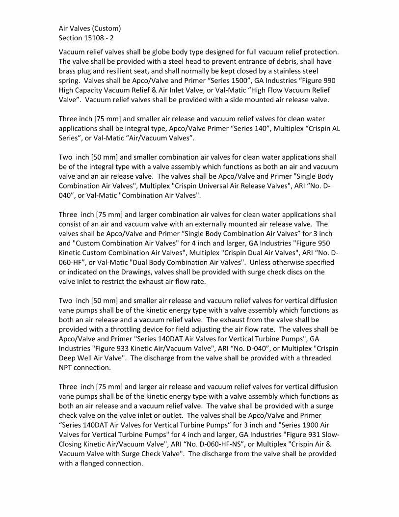
Air Valves (Custom) Section 15108 - 2
Vacuum relief valves shall be globe body type designed for full vacuum relief protection. The valve shall be provided with a steel head to prevent entrance of debris, shall have brass plug and resilient seat, and shall normally be kept closed by a stainless steel spring. Valves shall be Apco/Valve and Primer “Series 1500”, GA Industries “Figure 990 High Capacity Vacuum Relief & Air Inlet Valve, or Val-Matic “High Flow Vacuum Relief Valve”. Vacuum relief valves shall be provided with a side mounted air release valve. Three inch [75 mm] and smaller air release and vacuum relief valves for clean water applications shall be integral type, Apco/Valve Primer “Series 140”, Multiplex “Crispin AL Series”, or Val-Matic “Air/Vacuum Valves”. Two inch [50 mm] and smaller combination air valves for clean water applications shall be of the integral type with a valve assembly which functions as both an air and vacuum valve and an air release valve. The valves shall be Apco/Valve and Primer "Single Body Combination Air Valves", Multiplex "Crispin Universal Air Release Valves", ARI “No. D-040”, or Val-Matic "Combination Air Valves". Three inch [75 mm] and larger combination air valves for clean water applications shall consist of an air and vacuum valve with an externally mounted air release valve. The valves shall be Apco/Valve and Primer “Single Body Combination Air Valves” for 3 inch and "Custom Combination Air Valves" for 4 inch and larger, GA Industries "Figure 950 Kinetic Custom Combination Air Valves", Multiplex "Crispin Dual Air Valves", ARI “No. D-060-HF”, or Val-Matic "Dual Body Combination Air Valves". Unless otherwise specified or indicated on the Drawings, valves shall be provided with surge check discs on the valve inlet to restrict the exhaust air flow rate. Two inch [50 mm] and smaller air release and vacuum relief valves for vertical diffusion vane pumps shall be of the kinetic energy type with a valve assembly which functions as both an air release and a vacuum relief valve. The exhaust from the valve shall be provided with a throttling device for field adjusting the air flow rate. The valves shall be Apco/Valve and Primer "Series 140DAT Air Valves for Vertical Turbine Pumps", GA Industries "Figure 933 Kinetic Air/Vacuum Valve", ARI “No. D-040”, or Multiplex "Crispin Deep Well Air Valve". The discharge from the valve shall be provided with a threaded NPT connection. Three inch [75 mm] and larger air release and vacuum relief valves for vertical diffusion vane pumps shall be of the kinetic energy type with a valve assembly which functions as both an air release and a vacuum relief valve. The valve shall be provided with a surge check valve on the valve inlet or outlet. The valves shall be Apco/Valve and Primer “Series 140DAT Air Valves for Vertical Turbine Pumps” for 3 inch and "Series 1900 Air Valves for Vertical Turbine Pumps" for 4 inch and larger, GA Industries "Figure 931 Slow-Closing Kinetic Air/Vacuum Valve", ARI “No. D-060-HF-NS”, or Multiplex "Crispin Air & Vacuum Valve with Surge Check Valve". The discharge from the valve shall be provided with a flanged connection.

Air Valves (Custom) Section 15108 - 3
2-2. MATERIALS. Except as modified or supplemented herein, materials of construction shall comply with the governing standard.
Valve Trim Austenitic stainless steel or polymer materials.
Float Austenitic stainless steel, polycarbonate, or foamed polypropylene.
Shop Coatings
Epoxy (NSF-61 Certified) PPG Amercoat “Amerlock 400 High Solids Epoxy”, Carboline “Carboguard 891”, Sherwin-Williams "Macropoxy 646NSF" or Tnemec “Series N140 Pota-Pox Plus”.
Epoxy PPG Amercoat “Amercoat 385 Epoxy”, Carboline “Carboguard 890”, Sherwin-Williams "Macropoxy 646" or Tnemec “Series N69 Hi-Build Epoxoline II”.
Rust-Preventive Compound
As recommended by manufacturer.
2-3. SHOP PAINTING. All interior and exterior ferrous metal surfaces, except stainless steel components, shall be shop painted for corrosion protection. The valve manufacturer's standard coating will be acceptable, provided it is functionally equivalent to the specified coating and is compatible with the specified field coating. Field painting is covered in the Protective Coatings section. Surfaces shall be painted as indicated:
Interior Surfaces of Valves in Clean Water Applications (Raw or Treated Water in Potable Water Facilities)
NSF-61 Certified Epoxy.
Interior Surfaces of Valves in Wastewater Applications
Epoxy
Exterior Surfaces of Valves To Be Installed in Manholes or Valve Vaults
Coal tar epoxy. Epoxy.
Exterior Surfaces of All Other Valves Universal primer.
Polished or Machined Surfaces Rust-preventive compound. Interior epoxy coatings for clean water valves shall comply with ANSI/AWWA C550/NSF 61. Interior coatings for all valves shall be free of holidays. The total dry film thickness of shop-applied coatings shall be not less than:

Air Valves (Custom) Section 15108 - 4
Type of Coating Minimum Dry Film Thickness
Epoxy 10 mils [250 μm]
Universal Primer 3 mils [75 μm] Each 4 inch [100 mm] and larger combination air valve shall be provided with a shutoff valve between the air and vacuum valve and the air release valve. PART 3 - EXECUTION 3-1. INSTALLATION. Air release and combination air valves shall be installed in accordance with the Valve Installation section. 3-2. Air Valve Schedule.
P&ID TAG ID
Valve Type
Location
Inlet/ Outlet
Size (in)
Orifice Size (in)
Inlet Type
Outlet Type
Max Working Pressure
(psi)
Contractor Supplied Valves
AVRV-0054 AVRV Forebay Influent Pipe - Northern Wells
4 125F 125F 70
AVRV-0055 AVRV Forebay Influent Pipe - Perris I
4 125F 125F 65
AVRV-0056 AVRV Forebay Influent Pipe 6 1/4 125F 125F 70
AVRV-2261 CAV Finished Water Header - After Static Mixer
4 5/32 125F 125F 110
AVRV-1010 AVRV (PS)
Transfer Pump Discharge 3 125F 125F 95
AVRV-1020 AVRV (PS)
Transfer Pump Discharge 3 125F 125F 95
AVRV-1030 AVRV (PS)
Transfer Pump Discharge 3 125F 125F 95
AVRV-1040 AVRV (PS)
Transfer Pump Discharge 3 125F 125F 95
AVRV-1060 CAV Transfer Pump Header 6 7/32 125F 125F 95
AVRV-1061 CAV Forebay Discharge to Perris I Desalter
4 5/32 125F 125F 95
AVRV-1062 CAV Forebay Discharge to Perris II Desalter
4 5/32 125F 125F 95
AVRV-1101 CAV Cartridge Filter Influent Header
2
3/16 125F 125F 75
AVRV-1102 AVAR Cartridge Filter Effluent Header
2 125F 125F 50
AVRV-1412 CAV RO Permeate Header to Decarbonator
3 5/16 125F 125F 15

Air Valves (Custom) Section 15108 - 5
P&ID TAG ID
Valve Type
Location
Inlet/ Outlet
Size (in)
Orifice Size (in)
Inlet Type
Outlet Type
Max Working Pressure
(psi)
AVRV-1414 AVAR RO CIP Return 2 T T 65
AVRV-1512 AVAR RO Concentrate Header 2 T T 25
AVRV-1603 AVAR RO CIP Return to Neu. And CIP Tank
2 T T 65
AVRV-1627 AVAR CIP Cartridge Filter Effluent
2 T T 65
AVRV-1725 AVAR RO Flush Header 1 T T 65
AVRV-2041 AVAR RO Bypass to Decarbonator No. 2 from Northern Well
3 125F 125F 25
AVRV-2042 AVAR RO Bypass to Decarbonator No. 2 from Cartridge Filter
3 125F 125F 25
AVRV-2043 AVAR RO Bypass to Decarbonator No. 2
3 125F 125F 25
AVRV-2044 AVAR Decarbonator No. 1 Bypass
2 125F 125F 25
AVRV-2045 AVAR Decarbonator No. 2 Bypass
2 T T 25
AVRV-2210 AVAR (PS)
Finish Water Pump Discharge - Small
2 T T 110
AVRV-2220 AVAR (PS)
Finish Water Pump Discharge - Small
2 T T 110
AVRV-2230 AVAR (PS)
Finish Water Pump Discharge - Large
3 125F 125F 110
AVRV-2255 AVAR Finished Water Header after Pumps
4 125F 125F 110
AVRV-2261 CAV Finished Water Header - After Static Mixer
4 5/32 125F 125F 110
AVRV-2262 AVAR PW DCDA Water Header 1 T T 110
AVRV-2263 AVAR Finished Water to Purge 1 T T 110
AVRV-9115 AVAR (PS)
Brine Pump Discharge No. 1
2 T T 75
AVRV-9125 AVAR (PS)
Brine Pump Discharge No. 2
2 T T 75
AVRV-9135 AVAR (PS)
Brine Pump Discharge No. 3
2 T T 75
AVRV-9145 CAV Brine Pump Discharge Header
3 1/8 125F 125F 75
ROSS Supplied Valves
AVRV-1210 AVAR (PS)
ROU 1 Feed Pump Discharge
* * * * *

Air Valves (Custom) Section 15108 - 6
P&ID TAG ID
Valve Type
Location
Inlet/ Outlet
Size (in)
Orifice Size (in)
Inlet Type
Outlet Type
Max Working Pressure
(psi)
AVRV-1220 AVAR (PS)
ROU 2 Feed Pump Discharge
* * * * *
AVRV-1230 AVAR (PS)
ROU 3 Feed Pump Discharge
* * * * *
AVRV-1310 * RO Unit 1 After Stage1 * * * * *
AVRV-1320 * RO Unit 2 After Stage1 * * * * *
AVRV-1330 * RO Unit 3 After Stage1 * * * * *
AVRV-1411 * ROU 1 Permeate * * * * *
AVRV-1421 * ROU 2 Permeate * * * * *
AVRV-1431 * ROU 3 Permeate * * * * *
AVRV-1511 * RO Concentrate Unit No. 1 * * * * *
AVRV-1521 * RO Concentrate Unit No. 2 * * * * *
AVRV-1531 * RO Concentrate Unit No. 3 * * * * *
AVRV-1618 * CIP Cartridge Filter Influent
* * * * *
AVRV-1620A * CIP Cartridge Filter * * * * *
AVRV-1620B * CIP Cartridge Filter * * * * *
AVRV-1710 * RO Flush Pump Discharge * * * * *
AVRV-1720 * RO Flush Pump Discharge * * * * *
* Valve Characteristics to be determined by equipment manufacturer in ROSS Shop Drawing Submittal.
Notes: (1) Abbreviation for types are as indicated:
AVRV Air Vacuum Air Release Valve AVRV(PS) Air Vacuum Air Release Valve for Vertical Diffusion Vane Pumps CAV Combination Air Valve (Dual Bodied or single bodied AVAR with ARV)
(2) Abbreviations for inlet/outlet types are as indicated: T Threaded, ANSI/ASME B1.20.1, NPT 125F Flanged, ANSI B16.1 Class 125 250F Flanged, ANSI B16.1 Class 250
(3) Additional miscellaneous Air Vacuum/Air Release valves that are not indicated by schedule, drawings or P&IDs may be required at high points caused by field pipe routing revisions or equipment layouts provided by MF and RO suppliers.

Air Valves (Custom) Section 15108 - 7
Additional ARVR’s required shall be 1” for pipe filling and draining. Working pressure to be determined by contractor based on the system to be served. Contractor to include allowance for the equipment and installation of four (4) miscellaneous air vacuum air release valves.
(4) For air valves not included on schedule or sizes not defined, Contractor shall assume a 2” air valve assembly per EMWD Standard Drawing B-367 for bidding purposes.
END OF SECTION

Air Valves (Custom) Section 15108 - 8
[PAGE LEFT INTENTIONALLY BLANK]

Flap Gates (Custom) Section 15115 - 1
SECTION 15115
FLAP GATES PART 1 - GENERAL 1-1. SCOPE. This section covers furnishing 4 inch and larger double pivot flap gates and appurtenances as specified herein and as indicated in the Flap Gate Schedule. 1-2. GENERAL. Equipment furnished under this section shall be fabricated and assembled in full conformity with Drawings, Specifications, engineering data, instructions, and recommendations of the equipment manufacturer, unless exceptions are noted by Engineer. Gates shall be furnished with all necessary parts and accessories indicated on the Drawings, specified, or otherwise required for a complete, properly operating installation and shall be the latest standard products of a manufacturer regularly engaged in the production of flap gates. 1-2.01. General Equipment Stipulations. The General Mechanical and Equipment Provisions section shall apply to all equipment furnished under this section. If requirements in this specification differ from those in the General Mechanical and Equipment Provisions section, the requirements specified herein shall take precedence. 1-2.02. Identification. Flap gates shall be tagged in accordance with the Equipment and Valve Identification section. 1-3. SUBMITTALS. Complete drawings, construction details, and specifications covering the flap gates and appurtenances shall be submitted in accordance with the General Conditions, Section F-29 Equipment and Material section. Each drawing shall be identified with the applicable flap gate number. PART 2 – PRODUCTS
2-1. SERVICE CONDITIONS. Flap gates to be installed in Process Drain pump station which serves RO CIP and Flush tank drains, analyzer drains and decarbonator drain. 2-2. PERFORMANCE AND DESIGN REQUIREMENTS. Flap gates shall be designed for the following conditions and requirements, in addition to the requirements indicated in the Flap Gate Schedule.

Flap Gates (Custom) Section 15115 - 2 Each gate shall be designed to automatically open whenever the unseating head exceeds the seating head by 0.30 foot [91 mm] or less, and to automatically close whenever the seating head exceeds the unseating head. 2-3. ACCEPTABLE MANUFACTURES. For circular flap gates acceptable manufactuers are Hydro Gate, M&H, and Rodney Hunt. 2-4. MATERIALS.
Gate Body and Cover Cast iron.
Hinge Arms Ductile iron or bronze.
Hinge Pins AISI Type 304 stainless steel.
Hinge Pin Bushings Bronze or teflon.
Adjusting Bolts and Locknuts AISI Type 304 stainless steel.
Metallic Seats Stainless steel.
Resilient Seats Neoprene or Buna-N.
Assembly Fasteners Stainless steel.
Thread Lubricant Jet-Lube "Nikal", John Crane "Thred Gard Nickel", Never-Seez "Pure Nickel Special", or Permatex "Nickel Anti-Seize".
Epoxy Enamel PPG-Amercoat “Amercoat 385 Epoxy”, Carboline “Carboguard 890”, Sherwin-Williams “Macropoxy 646” or Tnemec “Series N69 Hi-Build Epoxoline II”.
Coal Tar Epoxy High-build coal tar epoxy; PPG-Amercoat
"Amercoat 78HB Coal Tar Epoxy", Carboline "Bitumastic 300 M", Tnemec "46H-413 Hi-Build Tneme-Tar", or Sherwin-Williams "Hi-Mil Sher-Tar Epoxy".

Flap Gates (Custom) Section 15115 - 3
2-5. CONSTRUCTION. 2-5.01. Wall Thimbles. 2-5.02. Body. The body of each flap gate shall be of heavy pattern cast construction. All joint surfaces and bearing areas shall be machined. All pivots shall be bushed and provided with suitable fittings to permit periodic lubrication of each pivot pin and bushing. An accurately machined slot or dovetailed groove shall be provided to retain the seat. 2-5.03. Cover. The gate cover shall be of heavy pattern cast construction, adequately reinforced to withstand the maximum specified seating head without distortion. Unless otherwise specified, each cover shall have an accurately machined slot or dovetailed groove to retain the seat. When resilient seats are specified in the Flap Gate Schedule, the gates shall be furnished with either a metallic cover seat or an accurately machined seating surface affording full contact with the resilient body seat when the gate is fully closed. 2-5.04. Seats. Seats shall be metallic or resilient, as indicated in the Flap Gate Schedule. Metallic seats shall fill the finished grooves and shall be pressed or suitably expanded into the grooves in a manner which will ensure that the seats will remain in place and free from distortion during the life of the gate. Seat faces shall be machined to at least a 60 microinch [1.5 µm] finish. Resilient seats shall fill and be permanently bonded into the groove in the gate body. 2-5.05. Hinge Arms. Hinge arms shall be of heavy pattern cast construction, with two pivot joints per arm, an adjustable lower pivot with limited rotation, and an adjustable upper hinge post or lug arrangement to permit adjustment of gate opening sensitivity to unseating heads. 2-5.06. Shop Painting. All iron and steel surfaces, except machined surfaces, which will be fully or partially submerged shall be shop painted with coal tar epoxy or epoxy enamel for gates installed in non-potable water facilities. The shop coating shall have a dry film thickness of at least 6 mils [150 µm] for epoxy enamel and 15 mils [380 µm] for coal tar epoxy. Refer to the General Mechanical and Equipment Provisions section for other shop painting requirements. 2-5.07. Accessories. When gates are installed for pump discharge service, as indicated in the Flap Gate Schedule, they shall be provided with an anti-lock bar to prevent the

Flap Gates (Custom) Section 15115 - 4 cover from tipping forward and becoming lodged in the opening, and with a leaf spring or other suitable device to limit cover travel during pump operation. PART 3 – EXECUTION 3-1. INSTALLATION. Flap gates and appurtenances shall be installed in accordance with the Gate Installation section. 3-2. FLAP GATE SCHEDULE.
Tag Number Size (in) Location Ends
GFL-2202 48 Forebay Overflow Vault Thimble
GFL-2201 12 Pond Discharge FLG
GFL-2203 24 Forebay Overflow Vault Thimble
END OF SECTION
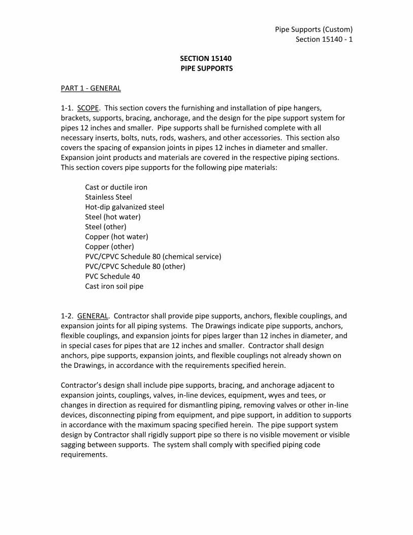
Pipe Supports (Custom) Section 15140 - 1
SECTION 15140 PIPE SUPPORTS
PART 1 - GENERAL 1-1. SCOPE. This section covers the furnishing and installation of pipe hangers, brackets, supports, bracing, anchorage, and the design for the pipe support system for pipes 12 inches and smaller. Pipe supports shall be furnished complete with all necessary inserts, bolts, nuts, rods, washers, and other accessories. This section also covers the spacing of expansion joints in pipes 12 inches in diameter and smaller. Expansion joint products and materials are covered in the respective piping sections. This section covers pipe supports for the following pipe materials:
Cast or ductile iron Stainless Steel Hot-dip galvanized steel Steel (hot water) Steel (other) Copper (hot water) Copper (other) PVC/CPVC Schedule 80 (chemical service) PVC/CPVC Schedule 80 (other) PVC Schedule 40 Cast iron soil pipe
1-2. GENERAL. Contractor shall provide pipe supports, anchors, flexible couplings, and expansion joints for all piping systems. The Drawings indicate pipe supports, anchors, flexible couplings, and expansion joints for pipes larger than 12 inches in diameter, and in special cases for pipes that are 12 inches and smaller. Contractor shall design anchors, pipe supports, expansion joints, and flexible couplings not already shown on the Drawings, in accordance with the requirements specified herein. Contractor’s design shall include pipe supports, bracing, and anchorage adjacent to expansion joints, couplings, valves, in-line devices, equipment, wyes and tees, or changes in direction as required for dismantling piping, removing valves or other in-line devices, disconnecting piping from equipment, and pipe support, in addition to supports in accordance with the maximum spacing specified herein. The pipe support system design by Contractor shall rigidly support pipe so there is no visible movement or visible sagging between supports. The system shall comply with specified piping code requirements.

Pipe Supports (Custom) Section 15140 - 2
Contractor shall not delete or relocate the supports, expansion joints, or couplings indicated on the Drawings without written approval of Engineer. 1-2.01. General Equipment Stipulations. The General Mechanical and Equipment Provisions section shall apply to all supports furnished under this section. If requirements in this specification differ from those in the General Equipment Stipulations, the requirements specified herein shall take precedence. 1-3. SUBMITTALS. Complete data, catalog information, and drawings covering fabricated pipe supports, fabricated inserts, and stainless steel, galvanized, and copper-plated and plastic-coated pipe supports shall be submitted in accordance with the General Conditions, Section F-29 Equipment and Material section. Data shall include a listing of the intended use and general location of each item submitted. When a wind and/or seismic design is required, Contractor shall submit confirmation of compliance with the Meteorological and Seismic Design Criteria section. PART 2 - PRODUCTS 2-1. MATERIALS. Unless otherwise indicated, all pipe supports shall comply with ANSI/MSS SP-58 and MSS SP-69. Materials of construction for fabricated steel supports are covered in the Structural and Miscellaneous Metals section. All pipe support materials shall be packaged as necessary to ensure delivery in satisfactory condition. Unless otherwise specified or indicated on the Drawings, pipe supports shall be fabricated of manufacturer's standard materials and provided with manufacturer's standard finish. Design loads for inserts, brackets, clamps, and other support items shall not exceed the manufacturer's recommended loads. Pipe supports shall be manufactured for the sizes and types of pipe to which they are applied. Strap hangers will not be acceptable. Threaded rods shall have sufficient threading to permit the maximum adjustment available in the support item. Continuously threaded rod is not acceptable for hanger rods over 12 inches [300 mm] in length. Unless accepted by Engineer, the use of supports which rely on stressed thermoplastic components to support the pipe will not be permitted.

Pipe Supports (Custom) Section 15140 - 3
Contact between dissimilar metals, including contact between stainless steel and carbon steel, shall be prevented. Portions of pipe supports which come into contact with other metals that are dissimilar shall be rubber or vinyl coated. Supports for brass or copper pipe or tubing shall be copper plated or plastic coated. Stainless steel supports shall be AISI Type 304 or 316 stainless steel, except for stainless steel supports fabricated by welding which shall be AISI Type 304L or 316L. Stainless steel supports shall be provided in all submerged locations. Hot-dip galvanized supports shall be in accordance with ASTM A153 and A385. Galvanized supports shall be provided in exterior and interior locations as an alternative to coated steel supports. Pipe support types and application shall comply with Table 1. 2-2. WIND AND SEISMIC LOADS. Wind and seismic loads for worst case conditions of either full, partially full, or empty pipes shall be considered in the design. Seismic design requirements for products specified herein shall be as indicated in the Meteorological and Seismic Design Criteria section. PART 3 - EXECUTION 3-1. APPLICATION. Concrete inserts or anchor bolts shall be used to support piping from new cast-in-place concrete. Fastening of supports to existing concrete and masonry shall be in accordance with the Anchorage in Concrete and Masonry section. Anchorage shall be provided to resist thrust due to temperature changes, changes in diameter or direction, or dead-ending. Anchors shall be located as specified to force expansion and contraction movement to occur at expansion joints, loops, or elbows, and as needed to prevent excessive bending stresses and opening of mechanical couplings. Anchorage for temperature changes shall be centered between elbows and mechanical joints used as expansion joints. Anchorage for bellows type expansion joints may be located adjacent to the joint. When expansion joints are required, pipe guides shall be provided adjacent to bellows type expansion joints. Guides will not be required where mechanical couplings are permitted as expansion joints. Guides shall be located on both sides of expansion joints, except where anchors are adjacent to the joint. Unless otherwise indicated on the Drawings, one guide shall be within four pipe diameters from the joint and a second guide within 14 pipe diameters from the first guide. Pipe supports shall allow adequate movement; pipe guides shall not be used for anchoring pipe against longitudinal forces. Pipe guides shall be provided at locations as recommended by the manufacturer.

Pipe Supports (Custom) Section 15140 - 4
Pipe supports for insulated cold piping systems shall be sized for the outside diameter of the insulated pipe, and an insulation protection shield shall be installed between the support and the insulation. Rigid insulation inserts shall be installed between the pipe and the insulation shields for piping larger than 2 inches [50 mm] or when needed to prevent crushing of the insulation. Inserts shall be of the same thickness as the adjacent insulation and shall be vapor sealed. Insulated hot piping systems shall be supported by clevises, clamps, support saddles, or rollers. Pipe clamps shall be attached directly to the pipe. Support saddles and rollers shall be sized for the outside diameter of the insulated pipe, and an insulation protection saddle shall be installed at the support. 3-2. TYPES OF SUPPORTS. The products for pipe supports shall be as indicated in Table 1 for the specified type and size of support. Where stainless steel is specified for pipe supports but is not available from the name suppliers for the model specified in Table 1, Contractor shall provide a heavier duty support that is available in stainless steel.
TABLE 1 - TYPES OF SUPPORTS
Description and Service
MSS SP 69 Type (Note
1) Specification Hangers 2-1/2 inch [63 mm] and
smaller pipe
For hot and cold insulated piping
Clevis 1 B-Line "B3100", Anvil "260" Piping Technology & Products Fig. 83.
Other services J-style 5 B-Line "B3690", Anvil "67",
Unistrut "J Hanger", or Piping Technology & Products Fig. 67.
Clevis 1 B-Line "B3104", Anvil "260", or Piping Technology & Products Fig 83.
3 Through 12 inch [75 through 300 mm] pipe (Note 3)
For hot insulated piping

Pipe Supports (Custom) Section 15140 - 5
TABLE 1 - TYPES OF SUPPORTS
Description and Service
MSS SP 69 Type (Note
1) Specification Double bolt 3 B-Line "B3144", Anvil "295", or
Piping Technology & Products Fig. 70.
For cold insulated piping
Clevis 1 B-Line "B3100", Anvil "260", or Piping Technology & Products Fig 83 .
For uninsulated cold piping
Clamp 4 B-Line "3140", Anvil "212", or Piping Technology & Products Fig. 50.
Clevis 1 B-Line "B3100", Anvil "260", or Piping Technology & Products Fig 83.
Other services Clevis 1 B-Line "B3100" or Anvil "260" for
steel pipe; B-Line "B3102", Anvil "590", or Piping Technology & Products Fig. 83 C. L. for cast iron pipe.
Concrete Inserts, Steel 12 inch [300 mm] and
smaller pipe 18 Channel 12 ga [2.66 mm thick],
galv, 1-5/8 by 1-3/8 inches [41.3 by 34.9 mm], min. 8 inches [200 mm] long, anchor lugs on 4 inch [100 mm] centers, at least three lugs, end caps, and filler strip.
Beam Clamps, Malleable Iron or Steel, 12 inch [300 mm] and smaller pipe
21 B-Line "3050" and "3055", Anvil "133" and "134", or Piping Technology & Products Fig. 130 and Fig. 130 (SP).
28, 29 Anvil "292" or Piping Technology & Products Fig. 140.

Pipe Supports (Custom) Section 15140 - 6
TABLE 1 - TYPES OF SUPPORTS
Description and Service
MSS SP 69 Type (Note
1) Specification 30 B-Line "3054", Anvil "228", or
Piping Technology & Products Fig. 140.
Side Beam Bracket 34 B-Line "B3062", Anvil "202", or Piping Technology & Products Fig. 20L.
Wall Supports and Frames, Steel, 12 inch [300 mm] and smaller pipe (Note 2)
Brackets 32 B-Line "B3066", Anvil "195", or Piping Technology & Products Fig. 76.
33 B-Line "B3067", Anvil "199", or Piping Technology & Products Fig. 76.
Prefabricated channels -- 12 ga [2.66 mm thick], galv, 1-5/8 inches [41.3 by 41.3 mm], with suitable brackets and pipe clamps.
Offset pipe clamp, 1-1/2 inch [38 mm] and smaller pipe
-- Galv, 1-1/4 by 3/16 inch [32 by 4.7 mm] steel, with 3/8 inch [9.5 mm] bolts.
Offset pipe clamp, 2 to 3-1/2 inch [50 to 88 mm] pipe
-- Galv, 1-1/4 by 1/4 inch [32 by 6 mm] steel, with 3/8 inch [9.5 mm] bolts.
Floor Supports, Steel or Cast Iron
6 inch [150 mm] and smaller pipe
37 (with base)
B-Line "B3090", Anvil "259" or Piping Technology & Products Fig. 48.
8 through 12 inch [200 to 300 mm] pipe
38 B-Line "B3093", Anvil "264" or Piping Technology & Products Fig. 46.
Pipe Alignment Guides -- B-Line "B3281" through "B3287", Anvil "255", or Piping Technology & Products Fig. 6.

Pipe Supports (Custom) Section 15140 - 7
TABLE 1 - TYPES OF SUPPORTS
Description and Service
MSS SP 69 Type (Note
1) Specification Turnbuckles Steel 13 B-Line "B3202", Anvil "230", or
Piping Technology & Products Fig. 30.
Hanger Rods, Carbon Steel, Threaded Both Ends, 3/8 inch [10 mm] minimum size
-- B-Line "B3205", Anvil "140", or Piping Technology & Products Fig. 128.
Weldless Eye Nut, steel 17 B-Line "B3200", Anvil "290", or Piping Technology & Products Fig. 40.
Insulation Protection Saddle 39 B-Line "B3160 Series", Anvil "160 Series", or Piping Technology & Products Fig. 184.
Insulation Protection Shield 40 B-Line "B3151", Anvil "167", or Piping Technology & Products Fig. 183.
Table 1 Notes:
1. MSS SP-69 supports and hangers are illustrated on Figure 1-15140. 2. Pipe clamps or other devices which rely on the application of a clamping
force to the supported pipe in order to maintain the clamp position or location in a prefabricated channel or track will not be acceptable for use with nonmetallic pipe or tubing.
3. Alternatively, pipe hangers for 12 inch pipe may be saddle type as indicated on the Drawings.
3-3. SUPPORT SPACINGS. Pipe supports and expansion joints shall be spaced in accordance with Tables 2, 3, 4, and 5. The types of pipes to be supported are as specified herein. Table 2 covers spacings for the standard operating conditions specified for each pipe material. Tables 3 and 4 cover PVC and FRP pipe spacings where operating conditions are in excess of the temperature and specific gravity requirements covered in Table 2. Table 5 covers PVC and FRP pipe which carries air or liquids with a specific gravity other than 1.0. Spacing in the tables is the maximum spacing considering gravity loads. Where Contractor’s design includes lateral and longitudinal forces due to seismic loads, wind loads, and other forces, the spacing requirement may be less than that indicated in the tables.

Pipe Supports (Custom) Section 15140 - 8
TABLE 2 – MAXIMUM PIPE SUPPORT SPACING AT STANDARD TEMPERATURES AND SERVICES
Type of Pipe
Pipe Support Max Spacing
Max Run Without
Expansion Joint, Loop, or
Bend (Note 1)
Expansion Joint Max Spacing (Note 2)
Type of Expansion
Joints feet [m] feet [m] feet [m] Cast iron or Ductile iron
15 [4.5] 80 [24.4] 80 [24.4] Note 6
Steel, for hot water heating 1-1/4 inch
[31 mm] and smaller
7 [2.1] 30 [9.1] 100 [30.5] Note 3
1-1/2 to 4 inch [38 to 100 mm]
10 [3.0] 30 [9.1] 100 [30.5] Note 3
Over 4 inch [100 mm]
15 [4.5] 30 [9.1] 100 [30.5] Note 3
Steel, for other services 1-1/4 inch
[31 mm] and smaller
7 [2.1] 30 [9.1] 100 [30.5] Note 3
1-1/2 to 4 inch [38 to 100 mm]
10 [3.0] 30 [9.1] 100 [30.5] Note 3
Over 4 inch [100 mm]
15 [4.5] 80 [24.4] 80 [24.4] Note 6
Stainless steel 1-1/4 inch
[31 mm] and smaller
7 [2.1] 30 [9.1] 100 [30.5] Note 3
1-1/2 to 4 inch [38 to 100 mm]
10 [3.0] 30 [9.1] 100 [30.5] Note 3
Over 4 inch [100 mm]
15 [4.5] 80 [24.4] 80 [24.5] Note 3
Copper, for hot water 1 inch [25 mm]
and smaller 5 [1.5] 20 [6.1] 100 [30.5] Note 3
Over 1 inch [25 mm]
7 [2.1] 20 [6.1] 100 [30.5] Note 3
Copper, for services other than hot water 1 inch [25 mm]
and smaller 5 [1.5] -- -- Note 7

Pipe Supports (Custom) Section 15140 - 9
TABLE 2 – MAXIMUM PIPE SUPPORT SPACING AT STANDARD TEMPERATURES AND SERVICES
Type of Pipe
Pipe Support Max Spacing
Max Run Without
Expansion Joint, Loop, or
Bend (Note 1)
Expansion Joint Max Spacing (Note 2)
Type of Expansion
Joints feet [m] feet [m] feet [m] Over 1 inch
[25 mm] 7 [2.1] 50 [15.2] 100 [30.5] Note 3
PVC, Schedule 80, for alum solution, caustic soda solution, ferric chloride solution, and hypochlorite solution at a maximum temperature of 100°F [38°C]. 1/8 and
1/4 inch [3 and 6 mm]
Continuous Support
20 [6.1] 60 [18.3] Note 3
1/2 inch [13 mm]
3-1/2 [1] 20 [6.1] 60 [18.3] Note 3
3/4 inch [19 mm]
4 [1.2] 20 [6.1] 60 [18.3] Note 3
1 and 1-1/4 inch [25 and 31 mm]
4-1/2 [1.3] 20 [6.1] 60 [18.3] Note 3
1-1/2 and 2 inch [38 and 50 mm]
5 [1.5] 20 [6.1] 60 [18.3] Note 3
2-1/2 inch [63 mm]
5-1/2 [1.6] 20 [6.1] 60 [18.3] Note 3
3 inch [75 mm] 6-1/2 [1.9] 20 [6.1] 60 [18.3] Note 3 4 inch
[100 mm] 7 [2.1] 20 [6.1] 60 [18.3] Note 3
6 inch [150 mm]
8 [2.4] 20 [6.1] 60 [18.3] Note 3
8 inch [200 mm]
9 [2.7] 20 [6.1] 60 [18.3] Note 3
10 inch [250 mm]
9-1/2 [2.9] 20 [6.1] 60 [18.3] Note 3
12 inch [300 mm]
10 [3.0] 20 [6.1] 60 [18.3] Note 3
PVC, Schedule 80, for other services at a maximum temperature of 100°F [38°C] and a maximum specific gravity of 1.0.
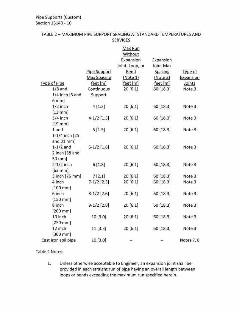
Pipe Supports (Custom) Section 15140 - 10
TABLE 2 – MAXIMUM PIPE SUPPORT SPACING AT STANDARD TEMPERATURES AND SERVICES
Type of Pipe
Pipe Support Max Spacing
Max Run Without
Expansion Joint, Loop, or
Bend (Note 1)
Expansion Joint Max Spacing (Note 2)
Type of Expansion
Joints feet [m] feet [m] feet [m] 1/8 and
1/4 inch [3 and 6 mm]
Continuous Support
20 [6.1] 60 [18.3] Note 3
1/2 inch [13 mm]
4 [1.2] 20 [6.1] 60 [18.3] Note 3
3/4 inch [19 mm]
4-1/2 [1.3] 20 [6.1] 60 [18.3] Note 3
1 and 1-1/4 inch [25 and 31 mm]
5 [1.5] 20 [6.1] 60 [18.3] Note 3
1-1/2 and 2 inch [38 and 50 mm]
5-1/2 [1.6] 20 [6.1] 60 [18.3] Note 3
2-1/2 inch [63 mm]
6 [1.8] 20 [6.1] 60 [18.3] Note 3
3 inch [75 mm] 7 [2.1] 20 [6.1] 60 [18.3] Note 3 4 inch
[100 mm] 7-1/2 [2.3] 20 [6.1] 60 [18.3] Note 3
6 inch [150 mm]
8-1/2 [2.6] 20 [6.1] 60 [18.3] Note 3
8 inch [200 mm]
9-1/2 [2.8] 20 [6.1] 60 [18.3] Note 3
10 inch [250 mm]
10 [3.0] 20 [6.1] 60 [18.3] Note 3
12 inch [300 mm]
11 [3.3] 20 [6.1] 60 [18.3] Note 3
Cast iron soil pipe 10 [3.0] -- -- Notes 7, 8 Table 2 Notes:
1. Unless otherwise acceptable to Engineer, an expansion joint shall be provided in each straight run of pipe having an overall length between loops or bends exceeding the maximum run specified herein.

Pipe Supports (Custom) Section 15140 - 11
2. Unless otherwise acceptable to Engineer, the spacing between expansion joints in any straight pipe run shall not exceed the maximum spacing specified herein.
3. Expansion joint fittings are specified in the respective piping sections. 4. At least two properly padded supports for each pipe section. 5. At least one support for each pipe section. 6. Expansion joints shall be mechanical couplings. 7. No expansion joints are required. 8. Supports for 5 and 10 foot [1.5 and 3 m] long pipe sections shall be located
within 18 inches [460 mm] of each joint. Supports shall be positioned to maintain the piping alignment and to prevent the piping from sagging.
9 References to specific gravity refer to liquid specific gravity and are referenced to water which is assumed to have a specific gravity of 1.0.
3-3.01. Temperature Adjustments for PVC Pipe. PVC pipe at a temperature above
100°F [38°C] shall have maximum support spacing in accordance with the following table. For insulated lines, reduce the support spacing to 70 percent of the listed values.
TABLE 3 – MAXIMUM PIPE SUPPORT SPACING FOR PVC PIPE AT NON-STANDARD
TEMPERATURES feet [meters]
Nominal Size Schedule 40 Schedule 80 inches [mm] 120°F [49°C] 140°F [60°C] 120°F [49°C] 140°F [60°C]
1/4 [6] Continuous Support Continuous Support 1/2 [13] 3 [0.9] 2-1/2 [0.7] 3-1/2 [1.0] 3 [0.9] 3/4 [19] 3-1/2 [1.0] 3 [0.9] 4 [1.2] 3 [0.9] 1 [25] 3-1/2 [1.0] 3 [0.9] 4-1/2 [1.3] 3-1/2 [1.0]
1-1/4 [31] 4 [1.2] 3-1/2 [1.0] 4-1/2 [1.3] 4 [1.2] 1-1/2 [38] 4 [1.2] 3-1/2 [1.0] 5 [1.5] 4 [1.2]
2 [50] 4-1/2 [1.3] 3-1/2 [1.0] 5 [1.5] 4-1/2 [1.3] 2-1/2 [63] 4-1/2 [1.3] 4 [1.2] 5-1/2 [1.6] 4-1/2 [1.3]
3 [75] 5 [1.5] 4 [1.2] 6 [1.8] 5 [1.5] 4 [100] 5-1/2 [1.6] 4-1/2 [1.3] 6-1/2 [1.9] 5-1/2 [1.6] 6 [150] 6-1/2 [1.9] 5 [1.5] 8 [2.4] 6-1/2 [1.9] 8 [200] 7 [2.1] 5-1/2 [1.6] 8-1.2 [2.5] 7 [2.1]
10 [250] 7-1/2 [2.2] 6 [1.8] 9 [2.7] 7-1/2 [2.2] 12 [300] 8 [2.4] 6-1/2 [1.9] 10 [3.0] 8-1/2 [2.5]
3-3.02. Temperature Adjustments for FRP Pipe. Not used 3-3.03. Specific Gravity Adjustments for PVC and FRP Pipe. PVC and FRP pipe shall have the maximum spacing indicated in Tables 2, and 3 are adjusted in accordance with the

Pipe Supports (Custom) Section 15140 - 12
following table when the specific gravity of the liquid is greater than 1.0. (Note: Specific gravities listed are liquid specific gravities referenced to water which is assumed to have a specific gravity of 1.0.) Table 4 shall not apply to PVC pipe containing alum solution, caustic soda solution, ferric chloride solution, and hypochlorite solution, as these services are specifically covered in Table 2.
TABLE 4 – MAXIMUM SUPPORT SPACING CORRECTION FACTORS FOR PVC AND FRP PIPE
Specific Gravity Correction Factor 1.0 1.00 1.1 0.98 1.2 0.96 1.4 0.93 1.6 0.90 2.0 0.85 2.5 0.80 Air 1.40
3-4. INSTALLATION. 3-4.01. General. All piping shall be supported in a manner which will prevent undue stress on any valve, fitting, or piece of equipment. In addition, pipe supports shall be provided at changes in direction or elevation, and adjacent to flexible couplings. Pipe supports and hangers shall not be installed in equipment access areas. Where horizontal piping is arranged with two or more parallel lines, trapeze hangers may be used in lieu of individual hangers. Trapeze assembly shall consist of structure attachments as previously specified with rod size dependent upon total weight supported. Spacing of assemblies shall be determined by the minimum pipe size included in the group supported. Trapeze horizontal assemblies shall be structural angle or channel section of sufficient size to prevent measurable sag between rods when pipes are full. All lines shall be attached to the horizontal with intermediate pipe guides and U-bolts or one-hole clamps. Pre-engineered support equipment may be used when selected and installed in accordance with the manufacturer's recommendations. Where copper pipe is installed on a support system of dissimilar metal with other pipes, the copper pipe shall be galvanically isolated from the support using Neoprene strips or other material acceptable to Engineer. No piping shall be supported from the pipe above.

Pipe Supports (Custom) Section 15140 - 13
Horizontal piping hanger support rods shall attach to steel beams with center-loading I-clamps, or welded beam clips. Hanger support rods shall attach to concrete slabs or beams with inserts. Anchorage shall be provided to resist both lateral and longitudinal seismic forces. 3-4.02. Inserts. Concrete inserts or anchor bolts shall be used to support piping from new cast-in-place concrete. Fastening of supports to existing concrete and masonry shall be in accordance with the Anchorage in Concrete and Masonry section. Reference building structural concrete Drawings for concrete inserts. When not provided as part of the building concrete structure, provide inserts for suspending hangers from reinforced concrete slabs and sides of reinforced concrete beams. Where concrete slabs form finished ceilings, provide inserts flush with the slab surface. Where inserts are omitted, drill through concrete slab from below and provide thru-bolt with recessed square steel plate and nut recessed into and grouted flush with slab. NDE (Non-Destructive Evaluation) shall be used to locate existing reinforcing before drilling. 3-4.03. Pipe Hangers and Supports. Install hangers to provide a minimum 1/2 inch [13 mm] space between finished covering and adjacent work. A hanger shall be placed within 18 inches [450 mm] of each horizontal elbow, and on both sides of all piping accessories and valves weighing 20 lbs [9 kg] or more. Hangers shall have 1-1/2 inches [38 mm] minimum vertical adjustment. Support horizontal cast iron, ductile iron and no-hub piping systems adjacent to each joint. Support vertical piping at every floor using riser clamps. Support riser piping independently of connected horizontal piping. Hanger and hanger components shall be sized specifically for the pipe size it is to be used on. 3-5. PLACEMENT. The maximum spacing for pipe supports and expansion joints shall be as indicated in Tables 2, 3, and 4. Rubber hose and flexible tubing shall be provided with continuous angle or channel support.

Pipe Supports (Custom) Section 15140 - 14
Unless otherwise indicated on the Drawings or acceptable to Engineer, piping shall be supported approximately 1-1/2 inches [38 mm] out from the face of walls and at least 3 inches [75 mm] below ceilings.
END OF SECTION


Valve And Gate Actuators (Custom) Section 15180 - 1
SECTION 15180 VALVE AND GATE ACTUATORS
PART 1 - GENERAL 1-1. SCOPE. This section covers furnishing manual and powered valve and gate actuators and accessories as specified herein. 1-2. GENERAL. Equipment provided under this section shall be fabricated and assembled in full conformity with Drawings, specifications, engineering data, instructions, and recommendations of the equipment manufacturer, unless exceptions are noted by Engineer. Actuators shall be furnished with all necessary parts and accessories indicated on the Drawings, specified, or otherwise required for a complete, properly operating installation and shall be the latest standard products of a manufacturer regularly engaged in the production of actuators. 1-2.01. General Equipment Stipulations. The General Mechanical and Equipment Provisions section shall apply to all equipment furnished under this section. If requirements in this specification differ from those in the the General Mechanical and Equipment Provisions section, the requirements specified herein shall take precedence. 1-2.02. Governing Standards. Except as modified or supplemented herein, cylinder and vane type actuators shall conform to applicable requirements of ANSI/AWWA C541. Except as modified or supplemented herein, electric motor actuators shall conform to applicable requirements of ANSI/AWWA C542. Except as modified or supplemented herein, actuators for butterfly and eccentric plug valves shall conform to the applicable requirements of ANSI/AWWA C504. Except as modified or supplemented herein, manual actuators for ball valves shall conform to the applicable requirements of ANSI/AWWA C507. Except as modified or supplemented herein, actuators for cast-iron slide gates shall conform to the applicable requirements of ANSI/AWWA C560. Except as modified or supplemented herein, actuators for open channel slide gates and weir gates shall conform to the applicable requirements of ANSI/AWWA C513.

Valve And Gate Actuators (Custom) Section 15180 - 2 Except as modified or supplemented herein, actuators for stainless steel slide gates shall conform to the applicable requirements of ANSI/AWWA C561. Except as modified or supplemented herein, actuators for composite slide gates shall conform to the applicable requirements of ANSI/AWWA C563. 1-2.03. Power Supply. Power supply to electric actuators will be as indicated in the valve and gate schedules. 1-2.04. Marking. Each actuator shall be marked with the manufacturer's name, model number, and the country of origin. An identifying serial number shall be stamped on a corrosion-resistant plate attached to the actuator. 1-2.05. Temporary Number Plates. Each actuator shall be factory tagged or marked to identify the actuator and the applicable valve or gate by number or service as indicated in the valve or gate schedule. 1-3. SUBMITTALS. Complete drawings, details, and specifications covering the actuators and their appurtenances shall be submitted in accordance with the General Conditions , Section F-29 Equipment and Material Items section. Submittal drawings shall clearly indicate the country of origin of each actuator and its components. Submittal drawings shall include separate wiring diagrams for each electrically operated or controlled actuator and the electrical control equipment. Each actuator drawing shall be identified with the respective valve number or name. For networked valve actuators, information on the available input and output assemblies shall be submitted for the protocol(s) specified to be provided. The submittal shall identify the version of the selected network protocol for which the device has been tested and certified. For electric or cylinder actuators, certified copies of reports covering proof-of-design testing of the actuators as set forth in Section 5 of ANSI/AWWA C541 or ANSI/AWWA C542 respectively, together with an affidavit of compliance as indicated in Section 6.3 of ANSI/AWWA C541 or ANSI/AWWA C542 respectively, shall be submitted to Engineer before the actuators are shipped. PART 2 - PRODUCTS 2-1. PERFORMANCE AND DESIGN REQUIREMENTS.

Valve And Gate Actuators (Custom) Section 15180 - 3
2-1.01. General. Actuators and appurtenances shall be designed for the conditions and requirements as indicated in the respective valve and gate sections. Liberal factors of safety shall be used throughout the design, especially in the design of parts subject to intermittent or alternating stresses. In general, working stresses shall not exceed one-third of the yield point or one-fifth of the ultimate strength of each material. 2-1.02. Valve Actuators. Each actuator shall be designed to open or close the valve under all operating conditions. Actuators shall be designed for the maximum pressure differential across the valve and maximum velocities through the valve where indicated in the respective valve schedules. Valve actuators shall be provided and adjusted by the valve manufacturer. Actuator mounting arrangements and positions shall facilitate operation and maintenance and shall be determined by the valve manufacturer unless indicated otherwise on the Drawings or directed by Engineer. When valves are to be buried, submerged, or installed in vaults; the actuators and accessories shall be sealed to prevent the entrance of water. The design water depth shall be as indicated in the respective valve schedules but not less than 20 feet [6.1 m]. 2-1.03. Gate Actuators. Actuators shall be sized to produce the torque or thrust required to operate the gate when subject to the seating and unseating operating heads as indicated in the respective gate schedules. Both the design head and the operating head shall be measured from the surface of the liquid to the center line of the gate. 2-1.04. Limit Switches. Limit switches shall be provided as indicated on the Drawings or in the valve and gate schedules. For manual or cylinder type actuators, each limit switch shall be heavy duty type, with a cast NEMA Type 4 enclosure, a spring return roller lever, and four isolated contacts (two normally open and two normally closed) rated 10 amperes at 120 to 480 volts ac and 5 amperes at 125 volts dc. The switches shall be Allen Bradley "802T" or Square D "9007 Type C". Limit switches for intelligent and standard electric actuators shall be as indicated in their respective paragraphs.

Valve And Gate Actuators (Custom) Section 15180 - 4 2-2. MATERIALS. Except as modified or supplemented herein, materials used in the manufacture of actuators shall conform to the requirements of the applicable governing standard(s). 2-3. VALVE MANUAL ACTUATORS. 2-3.01. General. Manual actuators of the types listed in the valve specifications or schedules shall be provided by the valve manufacturer. Unless otherwise indicated or specified, each geared manual actuator shall be equipped with an operating handwheel. The direction of rotation of the wheel, wrench nut, or lever to open the valve shall be to the left (counterclockwise). Each valve body or actuator shall have cast thereon the word "Open" and an arrow indicating the direction to open. The housing of traveling-nut type actuators shall be fitted with a removable cover which shall permit inspection and maintenance of the operating mechanism without removing the actuator from the valve. Travel limiting devices shall be provided inside the actuator for the open and closed positions. Travel limiting stop nuts or collars installed on the reach rod of traveling-nut type operating mechanisms shall be field adjustable and shall be locked in position by means of a removable roll pin, cotter pin, or other positive locking device. The use of stop nuts or adjustable shaft collars which rely on clamping force or setscrews to prevent rotation of the nut or collar on the reach rod will not be acceptable. Each actuator shall be designed so that shaft seal leakage cannot enter the actuator housing. Valves for throttling service shall be equipped with an infinitely variable locking device or a totally enclosed gear actuator. Actuators shall produce the required torque with a maximum pull of 40 lbs [356 N] on the lever, handwheel, or chain. Actuator components shall withstand, without damage, a pull of 200 lbs [890 N] on the handwheel or chainwheel or an input of 300 foot-lbs [407 J] on the operating nut. Manufacturers: Manual handwheel actuators shall be manufactured by Rodney Hunt Company, Waterman Industires, Inc., H. Fontaine or Engineer approved equal. 2-3.02. Handwheels. Handwheel diameters shall be at least 8 inches [200 mm] but not more than 24 inches [600 mm] for 30 inch [750 mm] and smaller valves and not more than 30 inches [750 mm] for 36 inch [900 mm] and larger valves.

Valve And Gate Actuators (Custom) Section 15180 - 5
2-3.03. Chainwheels. All valves with center lines more than 6'-0" [2.3 m] above the floor shall be provided with chainwheels and operating chains. Each chainwheel operated valve shall be equipped with a chain guide which will permit rapid handling of the operating chain without "gagging" of the wheel and will also permit reasonable side pull on the chain. Suitable extensions shall be provided, if necessary, to prevent interference of the chain with adjacent piping or equipment. Operating chains shall be hot-dip galvanized or zinc plated carbon steel and shall be looped to extend to within 4 feet [1.2 m] of the floor below the valve. 2-3.04. Levers. Levers shall be capable of being locked in at least five intermediate positions between fully open and fully closed. In any building or structure containing lever operated valves, at least two operating levers shall be provided for each size and type of lever operated valve. 2-3.05. Chain Levers. Suitable actuator extensions shall be provided, if necessary, to prevent interference of the chain with adjacent piping or equipment. Operating chains shall be hot-dip galvanized carbon steel and shall be looped to extend to within 4 feet [1.2 m] of the floor below the valve. 2-3.06. Wrench Nuts. Unless otherwise specified in the valve schedules or on the Drawings, wrench nuts shall be provided on all buried valves and on all valves that are to be operated through floor boxes. Unless otherwise directed by Owner, all wrench nuts shall comply with Section 4.4.13 of ANSI/AWWA C500. At least two operating keys shall be furnished for operation of the wrench nut operated valves. 2-3.07. Operating Stands. Operating stands shall be provided in the locations indicated on the Drawings or as indicated in the valve and gate schedules. Operating stands shall support the handwheel approximately 36 inches [900 mm] above the floor. A sleeve made from standard weight galvanized steel pipe shall be provided for the opening in the floor beneath each operating stand. When stems are 10 feet [3 m] or longer, a suitable thrust bearing shall be provided in each operating stand to carry the weight of the extension stem. 2-3.08. Wall Brackets. Wall brackets shall be provided to support manual actuators in the locations indicated on the Drawings or in the respective valve schedules. The horizontal face of the bracket shall be predrilled to accept the actuator and the stem without modification. The top of the bracket shall extend sufficiently to bear on and transfer thrust loads to the top of the supporting structure. 2-4. GATE MANUAL ACTUATORS.

Valve And Gate Actuators (Custom) Section 15180 - 6 2-4.01. General. Manual actuators of the types listed in the gate schedules shall be provided by the gate manufacturer. Unless otherwise specified, actuators shall conform to ANSI/AWWA C560. All bearings and gears shall be totally enclosed in a weathertight housing having a sufficient number of fittings to permit periodic lubrication of all internal moving components without partial or total disassembly of the mechanism. The pinion shaft of crank-operated mechanisms shall be supported by roller bearings or needle bearings. The direction of rotation of the wheel, crank, or wrench nut to open the gate shall be to the left (counterclockwise). Actuators for rising stem self-contained gates shall be designed for mounting directly on the frame yoke. When indicated in the gate schedules, crank-operated actuators shall be suitable for operation with a portable actuator specified herein. A suitable adapter coupling shall be furnished with each crank actuator to couple the portable actuator to the crank actuator pinion shaft as required. 2-4.02. Floorstands. Floorstands shall be designed to transfer operating thrusts to the supporting structure. Each floorstand shall be designed to position the crank or the handwheel approximately 36 inches [900 mm] above the frame yoke, supporting surface, or adjacent operating floor or platform. 2-4.03. Stem Covers. Rising stem manual actuators shall be provided with a stem cover as indicated in the gate schedules. Stem covers shall conform to Section 4.4 of ANSI/AWWA C560. 2-4.03.01. Plastic Covers. Covers shall be constructed of transparent plastic pipe and shall be furnished with an end cap, condensation vents, and a clear mylar position-indicating marking tape. The marking tape shall be adhesive backed and shall be permanently marked and calibrated in feet and inches [meters and millimeters]. The tape shall be applied to the stem cover after the gate has been installed and shall be so positioned that the height of the slide will be indicated by reference to the top of the stem. 2-4.06.02. Steel Covers. Covers shall be constructed from steel pipe and shall be furnished complete with a threaded end cap. All steel components of each cover shall be hot-dip galvanized following fabrication.

Valve And Gate Actuators (Custom) Section 15180 - 7
The operating mechanism shall be furnished with a digital or dial type mechanical position indicator. The indicator mechanism shall be installed inside a weatherproof housing and shall be clearly visible through a transparent, weatherproof window. 2-5. INTELLIGENT ELECTRIC ACTUATORS. 2-5.01. General. Intelligent electric actuators as listed in the valve and gate schedules shall be provided by the valve or gate manufacturer. Intelligent electric actuators with torque output requirements of 750 ft-lbs and less for butterfly valves and eccentric plug valves shall be quarter-turn type and shall be Auma "AUMATIC SQBV 05.1 through SQBV 12.1", EIM “HQ Series”, Limitorque "QX" or Rotork “IQT Series” without exception. All other intelligent electric actuators for open-close service shall be multi-turn type and shall be Auma “AUMATIC AC SABV 07.2 through SABV 16.2”, EIM “TEC2/TEC2000”, Limitorque "MX", or Rotork "IQ Series", without exception. Intelligent electric actuators for modulating service shall be Auma “AUMATIC AC SARBV 07.2 through SARBV 16.2”, EIM “TEC2/TEC2000”, Limitorque “MX”, or Rotork “IQ Series”, without exception. Intelligent electric actuators for explosion proof service shall be Auma “AUMATIC AC SAExBV/SARExBV 07.2 through SAExBV/SARExBV 16.2”, EIM “TEC2/TEC2000”, Limitorque “MX”, or Rotork “IQ Series” without exception. Intelligent electric actuators produced by other manufacturers are not acceptable. Intelligent electric actuators shall be capable of non-intrusive configuration without requiring removal of any actuator covers. Configuration of actuator functions shall be by use of a hand held infrared linked device, laptop or PDA with compatible wireless communication capability, or by local control switches and 32-character LCD display mounted on the actuator housing. The display language shall be English. Intelligent electric actuators shall be provided with the capability to connect to a network over which valve commands and status shall be communicated. The communication protocol shall be per ___________ . The actuator shall have been tested and certified for the latest version of this protocol to insure proper operation with the polling device.

Valve And Gate Actuators (Custom) Section 15180 - 8 Each intelligent electric actuator shall be furnished complete with a motor, gearing, handwheel, configurable output relays, torque sensors, lubricants, wiring, and terminals. Each actuator shall be constructed as a self-contained unit with a ductile iron or aluminum alloy housing, of a type as indicated in the valve and gate schedules, and shall be integrally assembled on the applicable valve or gate by the valve or gate manufacturer. Housings shall have two O-ring seals, one on the controls compartment and one on the terminal cover. Actuators shall be designed to cycle the valve or gate from the fully open to the fully closed position or the reverse in approximately 60 seconds or as indicated in the valve and gate schedules. Actuator motors may be mounted horizontally adjacent to or vertically above the reduction gearing. All gearing shall be oil or grease lubricated. 2-5.02. Motors. Motors shall be totally enclosed, high torque design made expressly for valve and gate actuator service, capable of operating the valve or gate under full differential pressure for two complete strokes or one complete cycle of travel without overheating. Motors shall be designed in accordance with NEMA standards and shall operate successfully at any voltage within 10 percent above or below rated voltage. Motor bearings shall be permanently lubricated. Motors shall be provided with stall, temperature, loss of phase, and reverse phase protection. Actuators shall be capable of indicating phase loss. Motors for open-close service shall be rated for a minimum of 60 starts per hour and motors for modulating service shall be rated for a minimum of 1,200 starts per hour. 2-5.03. Power Gearing. Power gearing shall consist of hardened steel spur or helical gears and alloy bronze or hardened steel worm gear, all suitably lubricated, designed for 100 percent overload, and effectively sealed against entrance of foreign matter. Steel gears shall be hardened to at least 350 Brinell. Planetary or cycloidal gearing, aluminum, mild steel, or nonmetallic gears will not be acceptable. Gearing shall be designed to be self-locking so that actuation of a torque switch or electronic torque protection device by a torque overload condition will not allow the actuator to restart until the torque overload has been eliminated. If a secondary gearbox is required, it shall be designed to withstand the locked rotor torque of the actuator. 2-5.04. Handwheel Mechanism. The handwheel shall not rotate during motor operation. During handwheel operation the motor shall not affect the actuator operation. The actuator shall be responsive to electrical power and control at all times and, when under electrical control, shall instantly disengage the handwheel. The handwheel shall rotate counterclockwise to open the valve. An arrow indicating the opening direction and the word "Open" shall be cast on the handwheel. The force

Valve And Gate Actuators (Custom) Section 15180 - 9
required to operate the handwheel shall not exceed 80 lbs [350 N]. The handwheel shall have a padlockable declutch lever. 2-5.05. Torque Sensing. Torque and thrust loads in both closing and opening directions shall be limited by a torque sensing device. Torque settings shall be adjustable and shall be indicated locally. The adjustment shall permit a variation of 40 to 100 percent of rated torque. 2-5.06. Terminal Facilities. Terminal facilities for connection to motor leads, switches, and control and indication signals shall be provided in a readily accessible terminal compartment. The terminal compartment shall have at least two openings for external electrical conduits, one sized at least 3/4 inch [19 mm] and the other at least 1-1/4 inches [31 mm]. Each terminal compartment shall be large enough to allow easy routing and termination of fifteen 12 AWG [4 mm2] conductors. 2-5.07. Controls Compartment. Each actuator shall be furnished with a sealed compartment containing a reversing controller, multi tap transformer, electronic controls, and monitoring and protection modules. Reversing controllers shall be both mechanically and electrically interlocked and provided with the necessary direct-operated auxiliary contacts for required interlocking and control. The multi tap transformer shall provide power for all internal circuits, and shall provide 120 VAC supply for remote controls as indicated in the valve and gate schedules, or in the schematics on the Drawings. Where not networked, actuators for valves or gates listed for modulating service in the valve and gate schedules shall be provided with a control module for position modulating type service. The control module shall be mounted within the controls compartment. The module shall accept a standard 4-20 mA dc analog input signal with a load impedance of not greater than 400 ohms. The control module shall contain adjustments for span, zero, gain, and deadband. Non-networked modulating actuators shall have a 4 to 20 mA output signal proportional to valve or gate position. 2-5.08. Local Controls. Each actuator shall have controller devices mounted on the actuator as indicated in the valve and gate schedules. 2-5.09. Remote Indication and Controls. Valve or gate position and actuator status indication for non-networked valves shall be provided by four configurable output relay contacts which can be selected to indicate any position of the valve or gate. Relays shall be configurable to the normally open or normally closed states. Relays shall maintain and update position indication during handwheel operation. Contacts shall be rated 5 A, 250 VAC, 30 VDC. When not used for position indication, any of the four configurable relays shall be selectable to signal one of the following:

Valve And Gate Actuators (Custom) Section 15180 - 10
Valve or gate opening, closing, or moving. Thermostat tripped, phase loss. Motor tripped on torque in mid travel, motor stalled. Remote mode selected. Local mode selected.
Valve or gate control commands and actuator status indication for networked valves shall be communicated over the network. The actuator shall accept remote controls through the network to open, close, and stop the actuator and shall also accept a position setpoint. Hardwired signals to the actuator shall prevent or allow the actuator to operate as indicated on the Drawings. A hardwired permissive, inhibit or emergency stop interlock(s) shall override commands transmitted through the network. At a minimum, the actuator shall transmit the following status information through network:
Valve opening, closing, or moving. Valve full open, full closed. Thermostat tripped, phase loss. Motor tripped on torque in mid travel, motor stalled. Remote mode selected. Local mode selected. Valve position. Valve torque.
2-5.10. Remote Electric Actuator Control Station. Elevated actuators at a height greater than 6 feet shall be furnished with a remote control station as indicated in the valve schedules and on the Drawings. The control station shall include red and green indicating lights for valve position status, and Local-Off-Remote and Open-Close selector switches for control. Power for the remote control station shall be provided from its respective actuator unit. The remote control station shall be rated NEMA 4X. Each device mounted on the remote control station shall have an engraved label or escutcheon plate indicating its respective function. The remote control station shall have an engraved tag indicating the tag number or description of the respective actuated valve or gate. 2-6. STANDARD ELECTRIC ACTUATORS.

Valve And Gate Actuators (Custom) Section 15180 - 11
2-6.01. General. Standard electric actuators as listed in the valve and gate schedules shall be provided by the valve or gate manufacturer. Electric actuators with torque output requirements of 750 ft-lbs and less for butterfly valves and eccentric plug valves shall be quarter-turn type and shall be Auma "SGBV 05.1 through SGBV 12.1", EIM “Series P, Q, or R” or Limitorque "LY" without exception. All other electric actuators for open-close service shall be multi-turn type and shall be Auma "SABV 07.1 through SABV 48.1", EIM “Series 2000”, Limitorque "L120", or Rotork “AWT Series” without exception. All other electric actuators for modulating service shall be multiturn type and shall be Auma "SARBV 07.1 through SARBV 16.1", EIM “Series 2000”, Limitorque "L120", or Rotork “AWT Series” without exception. All other electric actuators for Explosion-proof service shall be multiturn type and shall be Auma "SAExBV/SARExBV 07.1 through SAExBV/SARExBV 16.1", EIM “Series 2000”, Limitorque "L120", or Rotork “AWT Series” without exception. Electric actuators produced by other manufacturers are not acceptable. As an alternate to standard electric actuators, valve or gate manufacturers may provide intelligent electric actuators as specified herein. Each standard electric actuator shall be furnished complete with a motor, gearing, handwheel, limit switches and torque sensors, lubricants, heating elements, wiring, and terminals. Each actuator shall be constructed as a self-contained unit with a cast iron or aluminum alloy housing, of a type as indicated in the valve and gate schedules, and shall be integrally assembled on the applicable valve or gate by the valve or gate manufacturer. Actuators shall be designed to cycle the valve or gate from the fully open to the fully closed position or the reverse in approximately 60 seconds or as indicated in the valve and gate schedules. Actuator motors may be mounted horizontally adjacent to or vertically above the reduction gearing. All gearing shall be oil or grease lubricated. 2-6.02. Motors. Motors shall be totally enclosed, high torque design made expressly for valve and gate actuator service, capable of operating the valve or gate under full differential pressure for two complete strokes or one complete cycle of travel without overheating. Motors shall be designed in accordance with NEMA standards and shall

Valve And Gate Actuators (Custom) Section 15180 - 12 operate successfully at any voltage within 10 percent above or below rated voltage. Motor bearings shall be permanently lubricated. Motors for open-close service shall be rated for a minimum of 60 starts per hour and motors for modulating service shall be rated for a minimum of 1,200 starts per hour. 2-6.03. Power Gearing. Power gearing shall consist of hardened steel spur or helical gears and alloy bronze or hardened steel worm gear, all suitably lubricated, designed for 100 percent overload, and effectively sealed against entrance of foreign matter. Steel gears shall be hardened to at least 350 Brinell. Planetary or cycloidal gearing or aluminum, mild steel, or nonmetallic gears will not be acceptable. Gearing shall be designed to be self-locking so that actuation of a torque switch or electronic torque protection device by a torque overload condition will not allow the actuator to restart until the torque overload has been eliminated. If a secondary gear box is required, it shall be designed to withstand the locked rotor torque of the actuator. 2-6.04. Handwheel Mechanism. The handwheel shall not rotate during motor operation. During handwheel operation the motor shall not affect the actuator operation. The actuator shall be responsive to electrical power and control at all times and, when under electrical control, shall instantly disengage the handwheel. The handwheel shall rotate counterclockwise to open the valve. An arrow indicating the opening direction and the word "Open" shall be cast on the handwheel. The force required to operate the handwheel shall not exceed 80 lbs [350 N]. The handwheel shall have a padlockable declutch lever. 2-6.05. Torque Sensing. Torque and thrust loads in both closing and opening directions shall be limited by a torque sensing device. Each torque sensing device shall be provided with an adjustment setting indicator. The adjustment shall permit a variation of approximately 40 percent in torque setting. Switches shall have a rating of not less than 6 amperes at 120 volts ac and 0.5 ampere at 115 volts dc. 2-6.06. Limit Switches. Each standard electric actuator shall have a minimum of four internal limit switch assemblies which are field adjustable. Each switch assembly shall consist of at least three separate limit switches, shall be operated by the driving mechanism, and shall be independently adjustable to trip at any point at and between the fully open and fully closed valve positions. All switches shall have an inductive contact rating of not less than 15 amperes at 250 volts ac and 10 amperes at 30 volts dc with a switching load limited to 5 amperes maximum for both AC and DC. 2-6.07. Position Transmitter. When indicated in the valve and gate schedules, actuators shall be provided with an electronic type position transmitter. The transmitter output shall be an isolated 4-20 mA dc capable of driving an external load of 0 to 400 ohms. Accuracy of the transmitted signal shall be ±2 percent of span. Repeatability and

Valve And Gate Actuators (Custom) Section 15180 - 13
hysteresis shall be within 1 percent. The transmitter shall transmit to a remote position indicator which is specified in the Instrumentation section. 2-6.08. Heating Elements. Space heating elements shall be provided to prevent condensation in the motor and limit switch housing. Space heating elements shall not be required for actuators which are of a sealed design utilizing double O-ring seals in the motor and controls housing. Heating elements shall be rated 120 volts ac. Heaters shall be continuously energized. 2-6.09. Terminal Facilities. Terminal facilities for connection to motor leads, switches, position transmitter, and heating elements shall be provided in readily accessible terminal compartments. Each terminal compartment shall have at least two openings for external electrical conduits, one sized at least 3/4 inch [19 mm] and the other at least 1-1/4 inches [31 mm]. Each terminal compartment shall be large enough to allow easy routing and termination of fifteen 12 AWG [4 mm2] conductors. 2-6.10. Controller. Each valve or gate shall be furnished with a reversing controller located inside the actuator enclosure and shall have controller devices as indicated in the valve and gate schedules. The controller shall be equipped with:
a. A motor overload protective device in each phase or solid state motor protection.
b. A space heater element, rated 120 volts ac, sized to be continuously energized for prevention of condensation within the controller enclosure.
c. A fused control power circuit taken from one power lead on the load side of the breaker and line side of the reversing starter to ground. If power supply is greater than 120 volts ac, a control power transformer with fused secondary, with volt-ampere capacity suitable for starter control plus continuous service to space heater elements in motor housing, limit switch compartment, and controller enclosure.
d. A terminal block with connectors for all external controls. All leads from the actuator motor and limit switch assembly shall be routed to terminal connections in the controller for external connections to all other control devices.
e. Auxiliary control contacts as indicated in the electrical schematics.
Reversing controllers shall be both mechanically and electrically interlocked and shall be provided with the necessary direct-operated auxiliary contacts for required interlocking and control.

Valve And Gate Actuators (Custom) Section 15180 - 14 Valve controllers shall be expressly selected for long life and reliable, low maintenance service under rugged service conditions. 2-6.11. Control Module. Valves or gates indicated for modulating service in the valve and gate schedules shall be provided with a control module for position modulating type service. The control module shall be mounted within the valve actuator limit switch housing. The module shall accept a standard 4-20 mA dc analog input signal with a load impedance of not greater than 400 ohms. The control module shall contain adjustments for span, zero, gain, and deadband. The actuator shall have a slide-wire type position feedback potentiometer or electronic current position transmitter which provides a position feedback signal to the control module. 2-6.11.01. Control Performance. For any operating torque within the specified range of the valve actuator, the valve and actuator shall perform within these specified limits:
Linearity Linearity of actual valve position as compared to demand signal shall be within ±4 percent of span over the entire operating range.
Repeatability For any repeated demand signal to the valve actuator, the actual valve position shall be repeated.
Deadband Deadband of the valve actuator shall be adjustable from 1 to 10 percent of span.
Hysteresis For any repeated demand signal to the valve actuator, from either an increasing or a decreasing direction, the actual valve position shall be repeated within 1 degree of valve shaft rotation.
2-6.12. Remote Electric Actuator Control Station. Elevated actuators at a height greater than 6 feet with a remote control station as indicated in the valve schedules and on the Drawings. The control station shall include red and green indicating lights for valve position status, and Local-Off-Remote and Open-Close selector switches for control. Power for the remote control station shall be provided from its respective actuator unit. The remote control station shall be rated NEMA 4X. Each device mounted on the remote control station shall have an engraved label or escutcheon plate indicating its respective function. The remote control station shall have an engraved tag indicating the tag number or description of the respective actuated valve or gate. 2-7. HYDRAULIC CYLINDER ACTUATORS. Not used.

Valve And Gate Actuators (Custom) Section 15180 - 15
2-8. AIR CYLINDER ACTUATORS. Not used. 2-9. VANE TYPE PNEUMATIC ACTUATORS. Not used. 2-10. AIR-OIL CYLINDER ACTUATORS. Not used. 2-12. PORTABLE HYDRAULIC ACTUATORS. Not used 2-13. ACTUATOR ACCESSORIES. 2-13.01. Extension Stems. Extension stems and stem guides shall be furnished when indicated in the respective valve schedules, indicated on the Drawings, or otherwise required for proper valve operation. Extension stems shall be of solid steel and shall be not smaller in diameter than the stem of the actuator shaft. Extension stems shall be connected to the actuator with a single Lovejoy "Type D" universal joint with grease-filled protective boot. All stem connections shall be pinned. At least two stem guides shall be furnished with each extension stem, except for buried valves. Stem guides shall be of cast iron, bronze bushed, and adjustable in two directions. Stem guide spacing shall not exceed 100 times the stem diameter or 10 feet [3 m], whichever is smaller. The top stem guide shall be designed to carry the weight of the extension stem. The extension stem shall be provided with a collar pinned to the stem and bearing against the stem thrust guide. Extension stems for chemical resistant butterfly valves located in drainage sumps shall be the two-piece type with stainless steel stem, PVC housing, wall support, and collar. Unless otherwise indicated on the Drawings, the length of the stem extension shall be as necessary to position the valve operator 12 inches above the maximum liquid level in the immediate area. Extension stems for buried valve actuators shall extend to within 6 inches [150 mm] of the ground surface, shall be centered in the valve box using spacers, and shall be equipped with a wrench nut. Extension stems for buried valve actuators shall be provided with position indicators as specified in the valve schedules. 2-13.02. Position Indicators. Unless otherwise specified, each valve actuator shall be provided with a position indicator to display the position of the plug or disc relative to the body seat opening.

Valve And Gate Actuators (Custom) Section 15180 - 16 For quarter turn plug, ball, or cone type valves installed in interior locations, the indicating pointer shall be mounted on the outer end of the valve operating shaft extension and shall operate over an indicating scale on the operating mechanism cover. Where the shaft passes through the cover, a suitable stuffing box or other seal shall be provided to prevent the entrance of water. Each actuator for butterfly valves, except where located in manholes, buried, or submerged, shall have a valve disc position indicator mounted on the end of the valve shaft. A disc position indicator shall also be provided on each operating stand or the actuator mounted thereon. 2-13.02.01. Position Indicators for Buried Actuators. When specified in the respective valve schedules, each buried valve actuator shall be equipped with a position indicator. Each indicator assembly shall be designed for installation on the extension stem connected to the operating stem of the buried actuator mechanism and shall be mounted in the top section of the valve box beneath the valve box cover. Each indicator shall be equipped with a wrench nut. Internal gearing shall be sealed and protected from the elements. 2-13.03. Torque Tubes. Torque tube shall utilize pipe rather than solid shafting between the valve input shaft and the output shaft of the valve floorstand operator. An adjustment of 2 inches [50 mm] shall be provided in the torque tube installation. Torque tube shall be coated with the same material as the submerged valve. 2-13.04. Valve Boxes. Each valve buried to a depth of 4 feet [1.2 m] or less shall be provided with a slide type valve box. Valve boxes shall be cast iron, extension sleeve type, suitable for the depth of cover indicated on the Drawings. Only one extension will be allowed with each slide type valve box. Valve boxes shall be at least 5 inches [125 mm] in inside diameter, shall be at least 3/16 inch [4.7 mm] thick, and shall be provided with suitable cast iron bases and covers. Each valve buried deeper than 4 feet [1.2 m] shall be provided with a valve box consisting of a cast iron cover and a 6 inch [150 mm] Cast Iron Pipe section. The cover shall be Clay & Bailey "No. 2193". The pipe shaft shall extend from the valve to 5 inches [125 mm] inside the valve box cover. All parts of valve boxes, bases, and covers shall be shop coated with manufacturer's standard coating. Valve boxes which are to be provided with position indicators shall have top sections and covers designed for proper installation of the position indicator and accessories.

Valve And Gate Actuators (Custom) Section 15180 - 17
2-14. SHOP PAINTING. All ferrous metal surfaces, except bearing and finished surfaces and stainless steel components of valve actuators and accessories, shall be shop painted for corrosion protection. The valve manufacturer's standard coating will be acceptable, provided it is functionally equivalent to the specified coating and is compatible with the specified field painting. The following surfaces shall be painted:
Polished or Machined Surfaces Rust-preventive compound.
Other Surfaces Epoxy.
Actuators and Accessories Universal primer.
PART 3 - EXECUTION 3-1. INSTALLATION. Actuators will be installed on the valves in accordance with the Valve Installation section and on gates in accordance with the Gate Installation section. 3-2. NETWORK SETUP. A manufacturer’s representative for the intelligent electric actuator manufacturer shall inspect all network terminations for conformity with the manufacturer’s recommended methods of terminating the network to each actuator, and shall notify the Contractor of any wiring modifications required. The manufacturer’s representative shall also set addresses for each valve and prove communication over the network. The valve manufacturer shall furnish the required information to the control system supplier that will allow the specified control and monitoring for each intelligent electric actuator. The Contractor shall coordinate these activities between the actuator manufacturer and the control system supplier.
END OF SECTION

Valve And Gate Actuators (Custom) Section 15180 - 18
[PAGE INTENTIONALLY LEFT BLANK]

Mechanical Insulation (Custom) Section 15250 - 1
SECTION 15250 MECHANICAL INSULATION
PART 1 - GENERAL 1-1. SCOPE. This section covers the furnishing and installation of insulation, jackets, and accessories for the following mechanical systems:
• piping
• ductwork Building insulation materials are specified in other sections. Insulation for mechanical equipment which is to be applied at the factory prior to shipment is specified in the individual equipment sections. Electrical heat tracing for piping shall be as specified in the Electrical section. 1-2. GENERAL. Materials furnished and installed under this section shall be in full conformity with the Drawings, Specifications, engineering data, instructions, and recommendations of the equipment manufacturer unless exceptions are noted by Engineer. 1-2.01. Coordination. Contractor shall be responsible for coordinating the installation of insulation with the installation of the items or systems to be insulated. Each item or system shall be tested and accepted by Engineer before installation of the insulation materials. Contractor shall verify that each component of the insulation systems is compatible with all other parts of the system; that all insulation materials are appropriate for the intended applications; and that all necessary devices and accessories have been provided. All insulation of the same class shall be the product of a single manufacturer; however, all the insulation types need not be the products of one manufacturer. 1-2.02. General Equipment Stipulations. The General Equipment Stipulations shall apply to all equipment furnished under this section. If requirements in this specification differ from those in the General Equipment Stipulations, the requirements specified herein shall take precedence. 1-2.03. Governing Standards. Except as modified or supplemented herein, all work covered by this section shall be performed in accordance with all applicable municipal

Mechanical Insulation (Custom) Section 15250 - 2
codes and ordinances, laws, and regulations. In case of a conflict between this section and any state law or local ordinance, the latter shall govern. All work shall comply with UL, NFPA, and ASTM safety requirements. 1-2.04. Metal Thickness. Metal thickness and gages specified herein are minimum requirements. Gages refer to US Standard gage. 1-2.05. Surface Burning Characteristics. Insulation, jackets, tapes, and adhesives to be used indoors shall have a composite flame spread rating not to exceed 25 and a composite smoke developed rating of 50 when tested by UL 723, NFPA 255, or ASTM E84. All testing shall be done on materials of the same densities and installed thicknesses as the materials being installed. Insulation materials which have been treated with a flame retardant additive to meet the required flame spread and smoke developed ratings are not acceptable. 1-2.06. Painting and Identification. Field painting and identification shall be as specified in the Protective Coatings section. Piping systems with electrical heat tracing shall have warning labels attach to the outside of the pipe thermal insulation weather barrier to indicate the presence of electric heat tracing. Labels shall be located every 10 feet of pipe, alternating on either side. The labels shall be black on yellow, weatherproof, mylar, with pressure sensitive adhesive and at least 2 inches by 6 inches minimum. 1-3. SUBMITTALS. 1-3.01. Drawings and Data. A complete list of materials and catalog cuts, together with detailed specifications, materials performance data, installation instructions, parts, devices, and accessories furnished, shall be submitted in accordance with the Submittals Procedures section. Information shall include certified test results to show compliance with UL, NFPA, and ASTM safety requirements. 1-4. QUALITY ASSURANCE. 1-4.01. Manufacturer Experience. A manufacturer shall have furnished material of the type specified which has been in successful operation for not less than the past 5 years. 1-5. DELIVERY, STORAGE, AND HANDLING. Shipping shall be in accordance with the Product Delivery Requirements section. Handling and storage shall be in accordance with the Product Storage and Handling Requirements section.

Mechanical Insulation (Custom) Section 15250 - 3
PART 2 - PRODUCTS 2-1. ACCEPTABLE MANUFACTURERS. Acceptable manufacturers shall be as listed in the respective product description paragraphs. 2-2. MATERIALS. Insulation, vapor retarders, and field applied jackets shall be installed to cover piping, ductwork, equipment, fittings, and appurtenances as indicated in the Insulation Schedule. 2-2.01. Pipe Insulation. 2-2.01.01. Type PMF1 Insulation. Type PMF1 mineral fiber pipe insulation shall be Johns Manville "Micro-Lok", Knauf "Pipe Insulation" or Owens-Corning. Type PMF1 pipe insulation shall be a one-piece molded glass fiber material with all-purpose jacket. The all-purpose jacket shall be factory-applied, fiberglass reinforced vapor barrier type, with white kraft bonded to aluminum foil and self sealing adhesive lap. The insulation shall be suitable for a temperature range of 0°F to 850°F, shall have a maximum thermal conductivity (k) of 0.24 Btu in/hr ft2 °F at 75°F and shall conform to ASTM C547. 2-2.01.02. Type PMW1 Insulation. Not used. 2-2.01.03. Type PFC1 Insulation. Type PFC1 flexible cellular elastomeric pipe insulation shall be Armacell "AP/Armaflex" or K-Flex USA "Insul-Tube" for unslit insulation and Armacell “AP/Armaflex SS” or K-Flex USA “Insul-Lock Seam-Seal” for factory pre-slit insulation. Flexible cellular polyolefin foam insulation shall be IMCOA "Imcolock" or Plastic Technology, Inc. “Innofoam”. Type PFC1 pipe insulation shall be one-piece, molded elastomeric or polyolefin foam insulation suitable for a temperature range of -40°F to 180°F, and shall have a maximum thermal conductivity (k) of 0.28 Btu in/hr ft2 °F at 75°F. The insulation shall be suitable for exposure to weather and direct sunlight or, where not indicated to be jacketed, shall be given two coats of an ultraviolet-resistant finish recommended by the manufacturer. Insulation shall conform to ASTM C534 for elastomeric or ASTM C1427 for polyolefin. 2-2.02. Duct Insulation. 2-2.02.01. Type DMF1 Insulation. Not used. 2-2.02.02. Type DMF2 Insulation. Type DMF2 flexible type duct insulation shall be Johns Manville "Microlite", Knauf "Friendly Feel Duct Wrap", or Owens-Corning “SOFTR All-Service Duct Wrap”.

Mechanical Insulation (Custom) Section 15250 - 4
Type DMF2 exterior insulation for round ductwork shall be 1 lb per cubic foot density flexible fiberglass duct wrap with factory-applied foil-scrim-kraft facing. Insulation suitable for temperatures of up to 250°F, and shall have a maximum thermal conductivity (k) of 0.27 Btu in/hr ft2 °F at 75°F. The insulation shall conform to ASTM C553.2-2.03. Equipment Insulation. 2-2.03.01. Type EMF1 Insulation. Not used. 2-4. ACCESSORIES. 2-4.01. PVC Insulation Jackets. Not used. 2-4.02. Aluminum Insulation Jackets. Aluminum insulation jackets for insulated piping systems shall be furnished and installed as indicated in the insulation schedule herein and where indicated on the Drawings. Aluminum jackets shall be manufactured from alclad conforming with ASTM B209. The aluminum jacket shall have a nominal thickness of 0.024 in., with an embossed finish. Fittings in insulated piping systems and equipment where indicated in the insulation schedule shall be provided with aluminum jackets of the same aluminum jacketing material as the piping systems. The jacket shall have a factory-applied moisture retarder of at least 3 mils permanently bonded to the interior surface and extending the full width of the jacket. The retarder shall consist of Polysurlyn or polyethylene film and kraft paper. PART 3 - EXECUTION 3-1. INSTALLATION. 3-1.01. General. Contractor shall install all insulation materials as specified herein for the piping systems, ductwork, and equipment that are not factory insulated. Insulation materials shall be installed in accordance with the manufacturer's written instructions and recommendations. Surfaces to be insulated shall be cleaned and dried. All work shall be performed within the temperature ranges recommended by the insulation product manufacturer. Insulation shall be kept clean and dry and shall remain in the factory container until it is installed. Packages or factory containers shall bear the manufacturer's stamp or label with the name of the manufacturer and description of materials. Seams of exposed insulation and jackets shall be in the least visible location. 3-1.02. Piping Insulation.

Mechanical Insulation (Custom) Section 15250 - 5
3-1.02.01. Type PMF1 Insulation. Pipe insulation, vapor retarders, and field applied jackets shall be installed to cover system piping, fittings, and appurtenances. Insulation shall be full factory unit lengths using a single cut piece to complete the run. Abutting cut pieces or scraps shall not be used. End joints and longitudinal seams shall be tightly butted. Insulation for fittings shall be of the same thickness and conductivity as the adjoining pipe insulation. Insulated piping conveying fluids at lower than ambient temperatures shall be jacketed with a continuous vapor barrier. The insulation shall be continuous through hangers and penetrations, except at firewall penetrations, and shall be sealed with vapor barrier coating. The vapor barrier coating shall be applied at intervals not exceeding 15 feet for straight runs and not more that 6 inches from fittings. Fibrous insulation laps and butt strips that are not self-sealing shall be secured with adhesive and stapled. Staples and seams shall be coated with vapor barrier material. On piping 2 inches and larger where the insulation is continuous through the hanger, an insert shall be installed between the support shield and piping. The insert shall be of the same thickness and contour as the adjacent insulation and installed to maintain a continuous vapor barrier through the support. The insert shall be constructed of wood or heavy density insulating material suitable for the system operating temperatures. 3-1.02.02. Type PMW1 Insulation. Not used. 3-1.02.03. Type PFC1 Insulation. Pipe insulation shall be installed to cover all pipe, fittings, and appurtenances with all seams and joints sealed by a factory or field applied adhesive. Insulation at fittings and appurtenances shall be carefully formed and fitted. Insulation at elbows shall be mitered using segments of pipe insulation. 3-1.03. Duct Insulation. Insulation for ducts indicated on the Drawings as wrapped shall be installed as specified herein and indicated on the Drawings. Duct insulation shall be continuous through hangers and penetrations, except firewall penetrations but shall be interrupted at thermometers, controls, damper linkages, flexible connections, access doors, etc., to avoid interference with their functioning and/or replacement. Insulation jackets shall be continuous across seams, reinforcement, and projections. Insulation on ducts conveying air at temperatures below 60°F shall be installed with a continuous vapor barrier seal. Staples and joints shall be sealed with a vapor barrier coating. 3-1.03.01. Type DMF1 Insulation. Not used.

Mechanical Insulation (Custom) Section 15250 - 6
3-1.03.02. Type DMF2 Insulation. Type DMF2 flexible insulation shall be installed with waterproof, fire-retardant adhesive. Insulation jackets shall overlap at least 2 inches and shall be secured under the overlap with adhesive and stapled on 4 inch centers. 3-1.04. Equipment Insulation. Not used. 3-1.05. PVC Jacketing. Not used. 3-1.06. Aluminum Jacketing. Aluminum jacketing for piping systems shall be installed as specified herein and indicated on the Drawings. Jacketing shall be held in place with stainless steel securing bands uniformly spaced at not more than 18 inches to produce tight joints without "bulging". The jacket shall overlap at least 2 inches at longitudinal and circumferential joints. Joints shall be overlapped and sealed with caulk to prevent moisture penetration, and longitudinal joints shall be placed to shed water. Exposed ends of pipe insulation shall be provided with covers constructed of the same material as the jacketing. Elbows shall be jacketed with spirally wrapped aluminum strips or individual mitered segments or gores cut to fit the insulation.

Mechanical Insulation (Custom) Section 15250 - 7
3-2. INSULATION SCHEDULE.
INSULATION SCHEDULE
Service Size Inches
Mechanical Insulation Notes
Type Thickness Inches
PIPING - INDOOR (CONCEALED OR EXPOSED)
Non-Potable Cold Water
Up to 3
4 & larger
PFC1
PFC1
3/4
1
(3)
(3)
Potable Cold Water
Up to 3
4 & larger
PFC1
PFC1
3/4
1
(3)
(3)
Potable Hot Water
Up to 1-1/4
1-1/2 & larger
PMF1
PMF1
1
1-1/2
(9)
(9)
Storm Drain Up to 8 [200] PFC1 3/4 [20] (3), (8)
PIPING - OUTDOOR (EXPOSED)
Piping with Heat Tracing
All PMF1 1-1/2 (1)
DUCTWORK
Round Within conditioned space
All other indoor locations
DMF2
DMF2
2
3
(6)
(5), (6)
Mechanical Insulation Types: FC - Flexible Cellular MF - Mineral Fiber MW - Mineral Wool

Mechanical Insulation (Custom) Section 15250 - 8
Notes:
(1) Aluminum jacket.
(2) PVC jackets shall be provided on exposed portions of insulated piping located less than 8 feet above finished floor. On all other portions of the insulated piping system PVC jackets shall be provided only for fittings.
(3) Insulation shall be provided for portions of the piping system which pass through space above finished ceilings or is exposed above equipment, electrical panels, or cabinets.
(4) Insulation shall be provided for exposed portions of the piping system located less than 8 feet above the finished floor or grade.
(5) Insulation shall be provided for outside air plenums and ducts that are located upstream of the heating coil or pass through unheated spaces after the heating coil, unless indicated to be internally lined.
(6) Insulation shall be provided for outside air plenums and ducts, air conditioning supply and return ducts, and dehumidifier reactivation air discharge ducts, unless indicated to be internally lined.
(7) Insulation thickness shall be sufficient to provide a cold face temperature not to exceed 150°F.
(8) The underside of all roof drains shall be insulated to a 1 foot radius from the center of the drain. All roof drain piping within 4 feet of the drain shall be insulated.
(9) Includes 8 feet of the cold water inlet piping to the water heater storage tank.
Unless otherwise indicated in the insulation schedule, all mechanical piping, ductwork, equipment, and accessories with an operating temperature in excess of 140°F and below 60°F shall be insulated.
END OF SECTION

Rev: 09/16/99
SPECIFICATIONS - DETAILED PROVISIONS Section 15340 - Manholes and Fittings
C O N T E N T S
PART 1 - GENERAL ............................................................................................................................. 1
1.01 REQUIREMENT .......................................................................................................................... 1 1.02 MEASUREMENT AND PAYMENT ............................................................................................... 1 1.03 GUARANTEE .............................................................................................................................. 1
PART 2 - PRODUCTS .......................................................................................................................... 1 2.01 MANHOLES ................................................................................................................................ 1 2.02 RINGS ........................................................................................................................................ 1 2.03 TOPS .......................................................................................................................................... 1 2.04 MANHOLE COVERS.................................................................................................................... 2 2.05 MANHOLE STEPS ....................................................................................................................... 2


Manholes and Fittings Section 15340 – 1
SECTION 15340 MANHOLES AND FITTINGS
PART 1 - GENERAL
1.01 REQUIREMENT Under this specification, the Contractor shall be required to furnish, deliver and unload within the time specified in the Contract Documents, the manholes and fittings as specified on the Bidding Sheets, shown on the Contract Drawings, and described in these specifications, except as otherwise approved in writing by the Engineer.
1.02 MEASUREMENT AND PAYMENT Payment for quantities of manholes will be made at the unit prices as stated on the Bidding Sheets.
1.03 GUARANTEE The Contractor shall guarantee all materials and workmanship of items furnished under these specifications to be free from defects for a period of one (1) year after final completion and acceptance of the entire contract work. The Contractor shall, at his own expense, repair or replace all defective materials or workmanship supplied by him found to be deficient with respect to any provisions of this specification.
PART 2 - PRODUCTS
2.01 MANHOLES All manhole rings, tops, and cones, as constructed in place, shall be designed for A.A.S.H.O. H-20 highway loading, and shall conform to District standard drawings and the requirements of ASTM C-478 and the following requirements.
2.02 RINGS All manhole rings shall be centrifugally spun or compactly vibrated in forms.
2.03 TOPS All manhole tops and cones shall be compactly vibrated in forms.

Manholes and Fittings Section 15340 – 2
2.04 MANHOLE COVERS All manhole covers and frames shall conform to District standard drawings and the requirements for Class 30 gray iron castings in ASTM Designation A-48, or Class 60 Ductile Iron castings in ASTM A-536. The castings shall be thoroughly cleaned and coated with commercial quality asphaltum paint. Frames and covers shall be matchmarked in pairs before delivery to the work site and must be machined matched between cover and frame to avoid rocking.
2.05 MANHOLE STEPS Manhole steps shall conform to District Standard Drawings and shall be constructed of 1/2" plain steel bar incapsulated with copolymer polypropylene plastic as approved by EMWD. Alternate to be approved by EMWD for casting-in-place.
END OF SECTION 15340

Plumbing (Custom)
Section 15400 - 1
Section 15400
PLUMBING
PART 1 - GENERAL
1-1. SCOPE. This section covers the furnishing and installation of materials, appliances,
fixtures, equipment, and appurtenances associated with the plumbing systems as
specified herein and as indicated on the Drawings. Additional requirements for
plumbing systems shall be as indicated in the schedules on the Drawings. Suitable
connections shall be provided for each fixture, piece of equipment, and appurtenance.
Pipe materials, valves, thermal insulation, and pipe supports which are not an integral
part of the fixture or piece of equipment and are not specified herein are covered in
other sections.
1-2. GENERAL. Materials furnished and installed under this section shall be fabricated,
assembled, erected, and placed in proper operating condition in full conformity with the
Drawings, Specifications, engineering data, instructions, and recommendations of the
manufacturer unless exceptions are noted by Engineer.
1-2.01. Coordination. Contractor shall verify that each component of the plumbing
system is compatible with all other parts of the system; that all piping and
appurtenances are appropriate; and that all devices necessary for a properly functioning
system have been provided.
Where two or more units of the same class of equipment are required, they shall be the
product of a single manufacturer; however, all the component parts of the system need
not be the products of one manufacturer.
Each manufacturer of commercial or industrial grade water heaters, shall have a local
service center, or with written consent of Engineer, shall be able to provide service from
other locations within 24 hours. The service center shall be equipped and staffed to
service the system and shall maintain a local parts supply. Information on equipment
manufacturers' representatives shall be included with the submittals.
Where several manufacturers' names have been listed in this section as possible
suppliers, only the products of the first manufacturer listed have been checked for size,
functions, and features.
1-2.02. General Mechanical and Equipment Provisions. The General Mechanical and
Equipment Provisions shall apply to all equipment and materials provided under this
section. If requirements in this specification differ from those in the General

Plumbing (Custom)
Section 15400 - 2
Mechanical and Equipment provisions, the requirements specified herein shall take
precedence.]
1-2.03. Seismic Design Requirements. Seismic design requirements for products
specified herein shall be as indicated in the Meteorological and Seismic Design Criteria
section.
1-2.04. Governing Standards. Except as modified or supplemented herein, all work
covered by this section shall be performed in accordance with all applicable municipal
codes and ordinances, laws, and regulations. In case of a conflict between this section
and any state law or local ordinance, the latter shall govern.
All work shall conform to the requirements of AGA, ASTM, NFPA, and UL safety
requirements.
1-2.05. Power Supply. Unless otherwise specified, power supply to equipment with
motors shall be as indicated on the Drawings. Power supply for controls shall be
120 volts, 60 Hz, single phase unless otherwise required for a properly operating system.
1-2.06. Metal Thickness. Metal thicknesses and gages specified herein are minimum
requirements. Gages refer to US Standard gage.
1-2.07. Mechanical Identification. Mechanical identification shall conform to the
requirements of the Basic Mechanical Building Systems Materials and Methods section.
1-3. SUBMITTALS.
1-3.01. Drawings and Data. Complete assembly and installation drawings, and wiring
and schematic diagrams, together with detailed specifications and data covering
materials, parts, devices, and accessories forming a part of the equipment furnished,
shall be submitted in accordance with the General Conditions, Section F-29 Equipment
and Material section. Device tag numbers indicated on the Drawings shall be
referenced on the wiring and schematic diagrams where applicable. The data and
specifications to be submitted for each unit shall include, but shall not be limited to, the
following:
Equipment, Piping Accessories, and Appurtenances
Name of manufacturer.
Type and model.
Construction materials, thicknesses, and finishes.
Capacities.
Pressure and temperature ratings.
Overall dimensions.

Plumbing (Custom)
Section 15400 - 3
Piping connection sizes and locations.
Net weight.
Horsepower [kW].
Power requirements.
Wiring diagrams.
Plumbing Fixtures
Name of manufacturer.
Type and model.
Construction materials, thicknesses, and finishes.
Water consumption data.
Overall dimensions.
Rough-in dimensions.
Piping connection sizes and locations.
Net weight.
Seismic Design Requirements
Confirmation of compliance with the requirements of the Meteorological
and Seismic Design Criteria section.
1-3.02. Operations and Maintenance Data and Manuals. Adequate operation and
maintenance information shall be supplied as required in the Maintenance Manuals
Requirements section. Operation and maintenance manuals shall be submitted in
accordance with the District's General Conditions, Section 01430, and as specified
herein.
Operation and maintenance manuals are required for electronic trap priming panels,
water closets, urinals, faucets and flush valves, emergency fixtures, electric water
coolers, water heaters, hose reels, water heater circulation pump and expansion tanks.
1-4. QUALITY ASSURANCE.
1-4.01. Welding Qualifications. All welding procedures and welding operators shall be
qualified by an independent testing laboratory in accordance with the applicable
provisions of AWS Standard Qualification Procedures. All procedure and operator
qualifications shall be in written form and subject to Engineer’s review. Accurate
records of operator and procedure qualifications shall be maintained by Contractor and
made available to Engineer upon request.
1-4.02. Qualification. The plumbing system installer shall be licensed as stipulated by
the authority having jurisdiction.
1-4.03. Manufacturer's Experience. [Unless the equipment manufacturer is specifically
named in this section, the manufacturer shall have furnished equipment of the type and
size specified which has been in successful operation for not less than the past 5 years.]

Plumbing (Custom)
Section 15400 - 4
1-4.04. Construction. Plumbing fixtures shall be constructed in accordance with the
following standards:
Enameled Cast Iron ANSI/ASME A112.19.1M
Vitreous China ANSI/ASME A112.19.2M
Stainless Steel ANSI/ASME A112.19.3M
Faucets ANSI/NSF 61
Electric water coolers shall be UL listed and certified in accordance with the Air
Conditioning and Refrigeration Institute (ARI) Standard 1010. All materials in contact
with water shall comply with the Reduction of Lead in Drinking Water Act. All plumbing
fittings and fixtures intended to convey or dispense water for human consumption shall
comply with the requirements of NSF/ANSI 61 and NSF/ANSI 372 for lead-free.
1-5. DELIVERY, STORAGE, AND HANDLING. Shipping, handling and storage shall be in
accordance with the General Mechanical and Equipment Provisions section.
1-6. EXTRA MATERIALS. Extra materials shall be furnished for each type and size of
plumbing fixture or equipment as required, in the quantities indicated below.
Part Number Required
Flushometer valve repair kits 1 per 5 fixtures
Water closet seats 1 per 10 fixtures
Faucet washer cartridge and O-ring kits 1 per 5 fixtures
Electric water heater elements 1 per heater
Water heater relief valves 1 per heater
Extra materials shall be packaged with labels indicating the contents of each package.
Each label shall indicate manufacturer's name, equipment name, part nomenclature,
part number, address of nearest distributor, and current list price. Extra materials shall
be delivered to Owner as directed.
Extra materials subject to deterioration such as ferrous metal items and electrical
components shall be properly protected by lubricants or desiccants and encapsulated in
hermetically sealed plastic wrapping.
PART 2 - PRODUCTS

Plumbing (Custom)
Section 15400 - 5
2-1. SERVICE CONDITIONS. All plumbing fixtures and equipment shall be designed and
selected to meet the specified conditions.
2-2. PERFORMANCE AND DESIGN REQUIREMENTS. All fixtures and equipment shall be
designed to meet the performance and design conditions specified herein and indicated
on the Drawings.
2-2.01. Dimensional Restrictions. Layout dimensions will vary between manufacturers
and the layout area indicated on the Drawings is based on typical values. Contractor
shall review the contract Drawings, the manufacturer’s layout drawings, and installation
requirements and shall make any modifications required for proper installation subject
to acceptance by Engineer.
2-3. ACCEPTABLE MANUFACTURERS. Acceptable manufacturers shall be as listed in the
respective product description paragraphs.
2-4. MANUFACTURE AND FABRICATION.
2-4.01. Anchor Bolts and Expansion Anchors. Anchor bolts, expansion anchors, nuts,
and washers shall be as indicated in the Anchorage In Concrete and Masonry section
unless otherwise indicated on the Drawings.
2-4.02. Surface Preparation. All iron and steel surfaces, except motors and speed
reducers, shall be shop cleaned by sandblasting or equivalent, in strict conformance
with the paint manufacturer’s recommendations. All mill scale, rust, and contaminants
shall be removed before shop primer is applied.
2-4.03. Shop Painting. All steel and iron surfaces shall be protected by suitable coatings
applied in the shop. Surfaces which will be inaccessible after assembly shall be
protected for the life of the equipment. Coatings shall be suitable for the environment
where the equipment is installed. Exposed surfaces shall be finished, thoroughly
cleaned, and filled as necessary to provide a smooth, uniform base for painting. Electric
motors, speed reducers, starters, and other self-contained or enclosed components
shall be shop primed or finished with an oil-resistant enamel or universal type primer
suitable for top coating in the field with a universal primer and aliphatic polyurethane
system.
Surfaces to be coated after installation shall be prepared for painting as recommended
by the paint manufacturer for the intended service, and then shop painted with one or
more coats of the specified primer.

Plumbing (Custom)
Section 15400 - 6
Surface finish damaged during installation shall be repaired to the satisfaction of
Engineer. Field painting shall conform to the requirements of the Protective Coatings
section.
2-4.04. Equipment Bases. Unless otherwise indicated or specified, all equipment shall
be installed on concrete bases at least 6 inches [150 mm] high. Each unit and its drive
assembly shall be supported on a single baseplate of neat design. Baseplates shall have
pads for anchoring all components. Baseplates will be anchored to the concrete base
with suitable anchor bolts.
2-4.05. Special Tools and Accessories. Equipment requiring periodic repair and
adjustment shall be furnished complete with all special tools, instruments, and
accessories required for proper maintenance. Equipment requiring special devices for
lifting or handling shall be furnished complete with those devices.]
2-4.06. Piping Systems. Unless otherwise specified herein, piping system materials shall
be as specified in other sections.
2-4.07. Valves. Unless otherwise specified herein, valves indicated to be a part of the
plumbing systems shall be as specified in other sections.
2-5. WATER SUPPLY PIPING ACCESSORIES.
2-5.01. Water Hammer Arresters. Water hammer arresters shall be either bellows or
piston type. Bellows type arresters shall consist of a stainless steel shell, a factory
charged and sealed compression chamber, a stainless steel or elastomer bellows, and a
stainless steel threaded adapter. Piston type arresters shall consist of a seamless Type L
copper shell, a seamlessly spun and factory charged air chamber, a factory lubricated
double or triple O-ring sealed piston, and a threaded copper adapter. Water hammer
arresters shall be tested and certified in accordance with American Society of Sanitary
Engineering (ASSE) Standard 1010. Arresters shall be rated for a maximum working
pressure of 350 psig and a temperature range of 33°F to 250°F . Water hammer
arresters shall be Smith "Hydrotrol", Josam "75000 Series Absorbotron", Wade
"Shokstop", or Sioux Chief "Hydra-Rester".
2-5.02. Trap Primers.
2-5.02.01. Flow Activated Trap Primers. Not used.
2-5.02.02. Pressure Activated Trap Primers. Not used.
2-5.02.03. Tailpiece Trap Primers. Not used.

Plumbing (Custom)
Section 15400 - 7
2-5.02.04. Electronic Trap Priming Panel. Electronic trap priming panels shall be
provided as indicated by the plumbing drawings denoted by a symbol “TPP” and an
identifying number. One half-inch copper tubes shall run from the electronic trap
priming panel to the traps. Trap primers shall be mounted in accessible locations.
Electronic trap priming panels shall consist of a panel, timer, 120 V solenoid, calibrated
manifold system and shall be manufactured by Precision Plumbing Products Inc. “PTS
Series”, Zurn, MIFAB, or equal. Reference the plumbing drawings for the number of
priming tubes required per trap priming panel.
2-5.03. Thermostatic Mixing Valves. Thermostatic mixing valves shall comply with ASSE
1017, shall be bronze or brass body, with stainless steel flow control components,
threaded end connections, rotating handle adjustment, lockable setpoint, and hot and
cold check stops. Valves shall be suitable for flow ranges and have temperature
adjustment ranges as indicated in the schedules. Temperature adjustment range shall
be 85°F [29 °C] to 120°F [49 °C]. Accuracy shall be within 3°F of setpoint. Thermostatic
mixing valves shall be manufactured by Symmons, Leonard, or Powers.
2-5.04. Vacuum Relief Valves. Vacuum relief valves shall have bronze or brass bodies
rated for 200 psig and shall be provided with male threaded inlet connections. The
valves shall open at 1/2 inch water column vacuum and shall have a venting capacity of
at least 15 cubic feet per minute. Vacuum relief valves shall be Watts Regulator "Model
LFN36", Cash Acme “VR-801”, or Apollo Valves “Model VR”.
2-5.05. Thermometers. Thermometers shall be Weksler Instruments "Adjust Angle",
Ashcroft "Series EI Everyangle" or Weiss Instruments, Inc. “Vari-angle”.
Thermometers shall be bimetal type and shall have a dial at least 4-1/2 inch diameter,
with black markings on a white background. Pointer travel shall span not less than
200 degrees nor more than 270 degrees. Each thermometer shall have a stainless steel
case, bezel, fittings, and stem and shall be hermetically sealed, with external pointer
adjustment and an acrylic or shatterproof glass window.
Each indicator shall be furnished with an angularly adjustable frame for convenient
viewing. Unless otherwise indicated, thermometer range shall be 0 to 200°F .
Each thermometer shall be furnished with a stainless steel thermowell for installation in
the piping systems. The thermowells shall have 3/4 inch NPT thread mounts, a
minimum pressure rating of 250 psig [1725 kPa gauge], and a nominal 4 inch insertion
length.
2-5.06. Strainers. Strainers shall be provided where indicated on the Drawings.
Strainer screen size shall be 20 mesh unless otherwise indicated. The blowoff from each
strainer shall be equipped with a shutoff valve.

Plumbing (Custom)
Section 15400 - 8
Strainers located in copper piping systems shall be Y-pattern type with bronze body,
threaded ends, and monel or stainless steel screens. Strainers shall be Watts “Series
LF777SI”, Apollo Valves “Model YB-LF” or Wilkins “Model YBXL”.
Strainers located in ductile iron piping systems shall be Y-pattern type with iron body,
flanged ends, and monel or stainless steel screens. Strainers shall be Hoffman Specialty
“Series 400” or Metraflex “Model TF”.
2-5.07. Hose Faucets. Hose faucets shall be constructed with nickel or chrome plated
cast brass body, solid brass stem, threaded bonnet, and “T” style handle. Hose faucets
shall be provided with a 3/4 inch male pipe thread inlet and a 3/4 inch male hose thread
outlet unless otherwise indicated on the Drawings. Hose faucets shall be Prier Brass
“Model C-138NP.75”, Arrowhead Brass Products, or Zurn.
Where indicated on the Drawings, hose faucets shall be equipped with hose connection
vacuum breakers. Hose connection vacuum breakers shall be provided with 3/4 inch [19
mm] hose thread ends, brass or bronze bodies, stainless steel stem, rubber seat, and
rubber disc. Hose connection vacuum breakers shall be of tamper-resistant design to
prevent removal, and shall comply with ASSE Standard 1011 requirements. Hose
connection vacuum breakers shall be equipped with manual drain. Hose connection
vacuum breakers shall be Febco “Series 731”, Watts Regulator Company “Series 8” or
Wilkins “Model BFP 8”.
2-5.08. Hose Valves. Each angle type hose valve shall consist of an angle valve and hose
nipple. Angle valves shall be Class 150 angle type with bronze body, PTFE disc, union
bonnet, rising stem, and threaded ends. Angle type hose valves shall be Stockham “B-
222T”, Milwaukee, or Powell. Hose nipples shall be one piece, cast brass or bronze, with
male NPT and male hose thread ends. A cap and chain shall be provided for hose valves
in interior locations. Hose nipples shall be Potter-Roemer, Inc. “2830 Series”, Croker
Corp., or Elkhart Brass.
Each in-line hose valve shall consist of a straight pattern globe valve. Straight pattern
type globe valves shall consist of a brass body with extended valve stem, handwheel,
union bonnet, rising stem, and threaded ends. In-line type hose valves shall be Potter-
Roemer, Inc. “4120 Series” or Guardian Fire Equipment, Inc. “5320 Series”.
All hose valves shall be 1-1/2 inch size unless otherwise indicated on the Drawings.}
2-5.09. Wall Hydrants. Wall hydrants shall be freezeproof type with bronze body,
polished bronze or chrome plated face, integral vacuum breaker, and removable handle
key. Wall hydrants shall be provided with ¾ inch pipe thread inlet and ¾ inch male hose
thread outlet. Wall hydrants shall be ASSE 1019-B approved. Wall hydrants shall be
Smith “Model 5619”, Zurn “Z1321-C”, or Prier “Model C-634”.

Plumbing (Custom)
Section 15400 - 9
2-5.10. Pressure Gauges. Pressure gauges shall be Ashcroft "Duragauge 1279",
Weksler, or Weiss Instruments, Inc.
Except as modified or supplemented herein, all gauges shall conform to the
requirements of ANSI B40.1. Accuracy shall be ANSI Grade A or better. Gauges shall be
indicating dial type with C-type phosphor bronze Bourdon tube, stainless steel rotary
geared movement, phenolic open-front turret, stainless steel or phenolic ring, case,
adjustable pointer, and acrylic or shatterproof glass window.
The dial shall be 4-1/2 inch [114 mm] in diameter with black markings on a white
background. The units of measurement shall be psi and shall be indicated on the dial
face. The pointer shall span not less than 200 degrees nor more than 270 degrees. The
range shall be selected so that the normal operating reading is near the midpoint of the
scale.
Each gauge shall be provided with a threaded end ball-type shutoff valve as specified in
the Ball Valves section.
All stem-mounted gauges shall be provided with 1/2 inch NPT connections.
2-5.10.01. Diaphragm Seals. Pipe-mounted diaphragm seals shall be provided where
indicated on the Drawings. Diaphragm seals shall be thread-attached type with
cleanout ANSI Type 316 stainless steel diaphragm, plated carbon steel upper housing,
and stainless steel lower housing. The diaphragm seal shall be of “continuous” design to
safely contain the process fluid in the event of gauge failure or removal from the system
under pressure. The lower housing shall be provided with a tapped ¼ inch [6.3 mm] NPT
flushing connection and an MxF stainless steel needle valve. Each gauge isolator and
the gauge served shall be factory assembled, filled with a suitable fluid, and calibrated
as a unit.
Gauge isolators shall be as manufactured by Ashcroft “Type 101”, Weksler, or Weiss
Instruments, Inc.
2-6. DRAINAGE AND VENT PIPING ACCESSORIES.
2-6.01. Cleanouts. Cleanouts shall be provided where indicated on the Drawings and
required by the referenced codes, and shall be of the required type.
Floor cleanouts shall consist of a two piece body, a threaded plug, an adjustable head,
and a cover. Cleanouts installed in floors that include a waterproofing membrane shall
be provided with a flashing flange and membrane clamp. Cleanouts installed in

Plumbing (Custom)
Section 15400 - 10
partition walls shall be provided with an access cover and frame with a securing screw
installed over the cleanout plug. Wall cleanout covers shall be stainless steel. Cleanouts
installed in exposed piping shall consist of a ferrule or threaded adapter and a cast brass
or bronze plug installed in a T-pattern, 90 degree drainage fitting.
Cast iron cleanouts shall be manufactured by Smith, Josam, or Wade. Polypropylene
cleanouts shall be manufactured by Orion, Enfield, or Zurn. PVC cleanouts shall be
manufactured by Sioux Chief, Plastic Oddities, or Zurn.]
2-6.02. Bell-Up Drains. Unless otherwise indicated, bell-up drains shall consist of a
drainage pipe hub extended to 1 inch [25 mm] above the finished floor. For chemical-
resistant waste systems, bell-up drains shall consist of a plain end section of pipe, with a
coupling extended 1 inch [25 mm] above the finished floor.
2-6.03. Funnel Receptors. Funnel receptors shall consist of cast iron funnels with cast
iron dome type bottom strainers. Funnel receptors shall be provided with waterstop
flange and threaded or no-hub outlet connections suitable for connection to the waste
piping. Funnel receptors connected to chemical resistant waste systems shall be
furnished with a factory applied chemical resistant interior coating. Unless otherwise
indicated, funnel receptors shall be installed 1 inch [25 mm] above the finished floor.
Funnel receptors shall be Smith “Series 3800 Figure SQ-3-1793-DBS”, Josam, or Wade.
2-6.04. Floor Drains. Floor drains shall be of the types specified herein and indicated on
the Drawings. Floor drains shall have a two-piece body, a flashing collar, an adjustable
head, and a grate. A trap primer connection shall be provided when indicated on the
Drawings. Floor drains installed in floors that include a waterproofing membrane shall
be provided with a flashing flange and membrane clamp.
Cast iron floor drains shall be manufactured by Smith, Josam, or Wade. Polypropylene
floor drains shall be manufactured by Orion, Enfield, Zurn. PVC floor drains shall be
manufactured by Sioux Chief, Plastic Oddities, or Zurn.
2-6.05. Roof Drains and Overflow Roof Drains. Roof drains and overflow roof drains
shall be of the types specified herein and indicated on the Drawings. Roof drains shall
consist of a cast iron dome, a cast iron body, a sump receiver, an integral flange, and an
extension for insulation thickness, where applicable. Drains for aggregate-surfaced
roofing shall be provided with gravel stops. For other than cast-in-place locations, roof
drains shall be provided with angle type underdeck clamps. When indicated on the
Drawings, overflow roof drains shall be provided with interior extension rings. Roof
drains and overflow roof drains shall be manufactured by Smith, Josam, or Wade.

Plumbing (Custom)
Section 15400 - 11
2-6.06. Downspout Nozzles. Downspout nozzles shall be cast brass or bronze, and shall
be provided with a threaded inlet and a mounting flange. The mounting flange shall be
provided with drilled fastening lugs. Downspout nozzles shall be Smith "Model 1770",
Josam, or Wade.
2-6.07. Modular Trench Drain System. Modular trench drain systems shall be of the
types specified herein and indicated on the Drawings. The modular trench drain system
shall include pre-sloped channel drain sections, end caps, outlet connections, grating,
and all other components and accessories required for a complete installation.
Drainage channels and related components shall be constructed of corrosion resistant
polymer concrete. The grating shall be suitable for extra heavy traffic. The modular
trench drain system shall be manufactured by Smith ACO, ABT Polydrain, or ACO
Polymer Products.
2-6.08. Floor Sinks. Floor sinks shall consist of a cast iron body with acid resistant
interior finish, and a nickel-bronze grate. The grate shall be of the type indicated on the
Drawings shall be easily removable for cleaning. Floor sink grates and outlets shall be
sized as indicated on the Drawings. Floor sinks shall be manufactured by Smith, Josam,
or Wade.
2-6.09. Backwater Valves. Not used.
2-6.10. Vent Flashings. Plumbing vent flashings shall be furnished and installed as
indicated on the Drawings.
2-7. PLUMBING FIXTURES AND ACCESSORIES.
2-7.01. General. Plumbing fixtures shall be provided with all required supports,
fasteners, supply and drain fittings, gaskets, and escutcheons required for a complete
installation.
2-7.02. Water Closets. Water closets shall be of vitreous china, with an elongated bowl
and siphon jet flushing action. The type and water use of water closets shall be as
indicated on the Drawings. All water closets shall be provided with anchor bolt caps.
Flush valve type water closets shall be provided with top spud connections for
flushometer valves. Flush tank type water closets shall be provided with factory
installed tank liners. Field installed liner kits will not be acceptable. Water closets shall
be manufactured by American Standard, Kohler, or Eljer.
2-7.02.01. Seats. Water closet seats shall be white, solid plastic, contoured, elongated
open front type without cover, with concealed check and stainless steel hinges. The
seats shall be manufactured by American Standard, Kohler, Eljer, or Church.

Plumbing (Custom)
Section 15400 - 12
2-7.02.02. Flush Valves. Flush valves for top spud type water closets shall be exposed
type, with a chrome plated brass body, an externally adjustable diaphragm, an angle
stop, a renewable valve seat, a tailpiece, a vacuum breaker, a wall flange, a spud nut
and flange, and a 1 inch [25 mm] NPT water supply connection. Flush valves shall be
Sloan "Royal 111", Delaney, or Zurn.
2-7.02.03. Supply Set. A supply set consisting of a 1/2 inch NPT brass angle loose key
stop valve, a copper supply tube, and an escutcheon plate shall be furnished for each
tank type water closet. All supply components shall be polished chrome.
2-7.02.04. Chair Carriers. Wall-mounted water closets shall be provided with adjustable
chair carriers. The carriers shall be suitable for the chase depth and piping arrangement
and shall consist of a heavy-duty cast iron body, complete with a drainage fitting, pylon
feet, a drainage nipple, fitting and fixture gaskets, a positioning frame or template, and
mounting hardware. Chair carriers shall be manufactured by Smith, Josam, or Wade.]
2-7.03. Urinals. Urinals shall be of the type and water use as indicated on the Drawings.
Urinals shall be of vitreous china, wall mounted, with an elongated rim and washout
flushing action, and shall be provided with a top spud connection for a flushometer
valve. Urinals shall be manufactured by American Standard, Kohler, or Eljer.
2-7.03.01. Flush Valves. Flush valves shall be exposed type, of chrome plated brass with
an externally adjustable diaphragm, an angle stop, a renewable valve seat, a tailpiece, a
vacuum breaker, a wall flange, a spud nut and flange, and a 3/4 inch [19 mm] NPT water
supply connections. Flush valves shall supply a maximum of 1 gallon [3.8 L] per flush,
and shall be Sloan "Royal 186", Delaney, or Zurn.
2-7.03.02. Supports. A fixture support system, including support legs, upper and lower
bearing plates, and bearing studs shall be provided for urinals mounted on all walls
other than masonry. Urinals mounted on masonry walls shall be provided with suitable
anchor bolts. Urinal supports shall be manufactured by Smith, Josam, or Wade.
2-7.04. Lavatories. Lavatory types, dimensions, and water use shall be as indicated on
the Drawings. Lavatories shall be of vitreous china, constructed with overflow drains
and soap depressions. Countertop lavatories shall be self-rimming, and shall be
provided with suitable adhesive and/or fastening clamps. Wall-mounted lavatories shall
be drilled for a concealed arm carrier. Faucet drillings shall be 4 inches [100 mm] on
center unless otherwise indicated. Lavatories shall be manufactured by American
Standard, Kohler, or Eljer.
2-7.04.01. Faucets and Trim. Lavatory faucets shall be 4 inches [100 mm] on center, of
polished chrome, with a vandal-resistant single-lever handle and all-brass or copper
waterways. Each faucet shall be provided with a flow restrictor, a cast brass grid

Plumbing (Custom)
Section 15400 - 13
strainer or pop-up drain as indicated on the Drawings, and a 1-1/4 inch [32 mm] cast
brass tailpiece. Flow restrictors shall limit water flow as required by the applicable
codes and standards. Supply sets consisting of 1/2 inch [12.5 mm] NPT brass angle loose
key stop valves, copper supply tubes, and escutcheon plates shall be furnished for each
lavatory faucet. All supply components shall be polished chrome. Where indicated to
be ADA compliant and exposed to human contact, lavatory supplies shall be insulated.
Lavatory faucets and supply sets shall be manufactured by American Standard, Kohler,
or Eljer.
2-7.04.02. Traps. Lavatory traps shall be at least 1-1/4 inches [32 mm] in diameter, cast
brass with polished chrome finish, with an escutcheon flange and a cleanout plug.
Where indicated to be ADA compliant and if exposed to human contact, lavatory traps
shall be offset, insulated type.
When insulation is needed, lavatory supplies and traps may be pre-insulated or
furnished with an insulation kit for field installation. Insulating material shall be flame
retardant closed cell vinyl. The supply insulating kit shall be snap form type or shall be
provided with ties. The trap insulation material shall not require the use of ties or
mechanical fasteners to be held in place. Pre-insulated traps and supply insulation kits
shall be McGuire Products "ProWrap". Trap and supply insulation kits shall be as
manufactured by IPS Corporation-Truebro, Plumberex, or Buckaroos, Inc.
2-7.04.03. Supports. Wall-hung lavatories shall be provided with a complete fixture
support system, including support legs, bearing plates, concealed arms, and anchor
bolts. The support legs shall be mounted within the partition wall. For lavatories
mounted on masonry walls, support legs may be omitted. Lavatory supports shall be
manufactured by Smith, Josam, or Wade.
2-7.05. Showers. Not used.
2-7.06. Stainless Steel Sinks. Sink types, dimensions, hole punching, metal gage, and
water use shall be as indicated on the Drawings.
Stainless steel sinks shall be seamless Type 304 stainless steel, with smooth radius
interior corners. All exposed surfaces of sinks shall be machine polished to a bright
finish and the underside shall be fully undercoated. Wall mounted sinks shall have
integral stainless steel support brackets and shall be furnished with a wall hanger. Sinks
shall be provided with mounting clips, support legs, and all other hardware as indicated
in the schedules. Stainless steel sinks shall be manufactured by Elkay, Just, or Advance
Tabco.
2-7.06.01. Faucets. Sink faucets shall be polished chrome, with a vandal-resistant
single-lever handle. All waterways shall be constructed of brass or copper. Faucets shall

Plumbing (Custom)
Section 15400 - 14
be provided with a brass spout, an aerator, and a flow restrictor. Supply sets consisting
of 1/2 inch NPT brass angle loose key stop valves, copper supply tubes, and escutcheon
plates shall be provided. All supply components shall be polished chrome. Sink faucets
and supply sets shall be manufactured by American Standard, Kohler, or Eljer.
2-7.06.02. Drain Assembly. All required drainage accessories, including strainers,
tailpieces, and traps, shall be provided. Basket strainers shall be heavy gage stainless
steel, with a removable conical strainer plate and a neoprene stopper. Tailpieces shall
be chrome plated brass. Sink traps shall be at least 1-1/2 inches in diameter, cast brass,
with polished chrome finish, an escutcheon flange, and a cleanout plug.
2-7.07. Janitors Sinks. Janitors sink types, dimensions, manufacturers, and models shall
be as indicated on the Drawings.
Mop sinks shall be floor mounted and constructed of pearl gray terrazzo. Mop sinks
shall be provided with an integral 20 gage [0.91 mm] thick stainless steel threshold cap,
a 6 inch [150 mm] drop at threshold, and a shoulder at least 1-1/4 inches [32 mm] wide.
A 3 inch [75 mm] cast brass drain and stainless steel strainer, and where indicated, a
20 gage [0.91 mm] thick stainless steel splash panel shall be provided for each sink.
Mop sinks shall be manufactured by Stern-Williams, Fiat, or Florestone Products
Company, Inc.
2-7.07.01. Faucets. Sink faucets shall be rough plated brass, with lever handles, a
threaded spout, a vacuum breaker, a wall brace, and a pail hook. The distance from the
wall to the center of the spout outlet shall measure approximately 7-1/2 inches . Sink
faucets shall be as manufactured by American Standard, Kohler, or Eljer.
2-7.07.02. Drain Assembly. Mop sinks shall be provided with a 3 inch [75 mm] cast
brass drain and a stainless steel strainer. Service sinks shall be provided with a 3 inch
[75 mm] cast iron P-type trap standard, with a stainless steel strainer, a cleanout plug,
and a threaded outlet.}
2-7.08. Emergency Fixtures. See the Emergency Eyewash/Shower Units section, 15430.
2-7.09. Wash Fountains. Not used.
2-7.10. Electric Water Coolers. Electric water cooler type, capacity, manufacturer, and
model shall be as indicated on the Drawings. Unit shall include bi-level electric water
cooler with bottle filling station Water coolers shall be wall mounted, mechanically
refrigerated type, and shall deliver 50°F [10°C] water at the specified rate, based on 80°F
[27°C] inlet water temperature and a room temperature of 90°F [32°C]. The water
coolers shall consist of a heavy gage steel cabinet and include vandal-resistant bubbler,
an insulated cooling tank, Bottle filling unit shall include an automatic 20-second shut-

Plumbing (Custom)
Section 15400 - 15
off timer. Shall include Green Ticker™ displaying count of plastic bottles saved from
waste. Bottle filler shall provide 1.1 - 1.5 gpm flow rate with laminar flow to minimize
splashing. A stainless-steel receptor, copper water lines, a water pressure regulating
valve, an adjustable thermostat, and a 3-wire power cord with a polarized plug. The
refrigeration unit shall consist of a hermetically sealed spring mounted compressor and
an air-cooled condenser. Electric water coolers shall be suitable for a 120-volt, 60 Hz,
single phase power supply, shall be UL and ARI listed, Unit shall be lead-free design
which is certified to NSF/ANSI 61 and 372 and meets federal and state low-lead
requirements. Unit shall be certified to UL399 and CAN/CSA 22.2 No. 120. and shall be
manufactured by Elkay, Oasis, or Halsey Taylor.
2-7.11. Food Waste Disposers. Not used.
2-8. PLUMBING EQUIPMENT.
2-8.01. General. Plumbing equipment shall be provided with all supports, fasteners,
fittings, and escutcheons required for a complete installation.
2-8.02. Water Heaters and Accessories. Water heaters shall be furnished and installed
where indicated on the Drawings. Heater type, storage capacity, recovery rate, energy
input, power supply requirements, manufacturer, and model shall be as indicated on
the Drawings.
2-8.02.01. Commercial Grade Electric Storage Water Heaters. Electric storage water
heaters shall be commercial type as indicated in the schedules, with a glass-lined tank
and one or more heating elements. The heater shall be provided with a cold water inlet
tube (top inlet), a magnesium anode, polyurethane foam insulation, a drain valve, and
adjustable thermostats. Heating elements shall be sheathed immersion type, low or
medium watt density, and shall be field replaceable. Heater tanks shall be ASME
stamped for a working pressure of at least 125 psig [862 kPa gauge]. Each heater shall
be equipped with an ASME rated pressure-temperature relief valve of suitable capacity.
Heaters shall be UL and NSF listed, and shall meet ASHRAE Standard 90.1 for energy
efficiency. The water heaters shall be manufactured by State Industries Inc., A. O.
Smith, or Lockinvar.
2-8.02.02. Industrial Grade Electric Storage Water Heaters.
2-8.02.03. Electric Instantaneous Water Heaters. Instantaneous water heaters shall be
tankless type and shall heat water on demand as determined by an integral flow switch.
Heaters shall be suitable for operating water pressures of 25 to 150 psig [14 to 1034 kPa
gauge], and shall be provided with compression type tubing connections. Heater
elements shall be constructed of stainless steel or glass reinforced plastic, and shall be
replaceable. If required by applicable codes, each heater shall be provided with a

Plumbing (Custom)
Section 15400 - 16
temperature and pressure relief valve. Heaters shall be provided with thermostatic
control. Electric instantaneous water heaters shall be UL listed and shall be
manufactured by Chronomite Laboratories Inc., Eemax, or Stiebel Eltron.
2-8.02.04. Commercial Grade Gas-Fired Water Heaters. Not used.
2-8.02.05. Industrial Grade Gas-Fired Water Heaters. Not used.
2-8.02.06. Water Heater Flues. Not used.
2-8.02.07. Circulating Pump. A circulating pump shall be furnished and installed where
indicated on the Drawings. Pump capacity, power requirements, manufacturer, and
model shall be as indicated on the Drawings.
The circulating pump shall be an in-line unit with a bronze body, bronze fitted,
mechanical seals, a stainless steel or ceramic shaft, and at least 1/2 inch [13 mm] NPT
connections. The circulating pump shall be controlled by a 7-day time clock provided
with the pump. Initial time clock setting shall energize the pump at 6:00 am and de-
energize the pump at 6:00 pm each day. The time clock shall be suitable for a 120 volt
single phase power supply, and shall have contacts rated for 10 amperes ac. The
circulating pump shall be manufactured by Bell & Gossett, Thrush, or Taco.
2-8.03. Neutralization Tanks. Not used.
2-8.04. Hose Reels. Hose reel type, capacity, manufacturer, and model shall be as
indicated on the Drawings.
Each hose reel shall be provided complete with a hose storage drum, a handle crank
winding mechanism, a spring-actuated pin lock, and a heavy duty frame suitable for
anchoring to concrete or masonry wall or floor supports. Unless indicated on the
Drawings to be stainless steel, hose reels shall be carbon steel with a baked epoxy
enamel finish. When indicated on the Drawings, hose reels shall be provided with a
water supply swivel joint rated at 600 psig [4,130 kPa gauge]. The hose storage drum
shall be provided with a brass male hose adapter suitable for use with the specified
hose. The hose reels shall be manufactured by Hannay, Potter-Roemer, or Reelcraft.]
2-8.05. Hoses. Hose type, diameter, manufacturer, and model shall be as indicated on
the Drawings.
Unless otherwise indicated, each hose shall be provided with one male swivel type brass
hose connector, one female brass hose connector, and one regulating wash-up spray
nozzle. Spray nozzles in 1 inch and 1-1/2 inch [38 mm] sizes shall be Potter-Roemer Inc.
"Series 2970" with a cast brass body, a rubber bumper, and a female hose thread.

Plumbing (Custom)
Section 15400 - 17
2-8.05.01. Type 1 Hoses. Type 1 hoses shall be non-collapsible, suitable for water
service and shall be rated for 150 psig [1030 kPa gauge] working pressure. The hose
shall consist of 1-1/2 inch [38 mm] ID heavy-duty ethylene, propylene diene (EPDM)
rubber tubing with synthetic, high tensile textile cord reinforcement and an EPDM
cover. Type 1 hoses shall be Gates Rubber Company "Water Master" or Potter-Roemer
“Model 2853”.
2-8.05.02. Type 2 Hoses. Type 2 hoses shall be non-collapsible, suitable for water
service and shall be rated for 150 psig [1030 kPa gauge] working pressure. The hose
shall consist of 3/4 inch [19 mm] ID heavy-duty ethylene, propylene diene (EPDM)
rubber tubing with synthetic, high tensile textile cord reinforcement and an EPDM
cover. Type 2 hoses shall be Gates Rubber Company "Adapta Flex" or Potter-Roemer
“Model 2851”.
2-8.05.03. Type 3 Hoses. Type 3 hoses shall be non-collapsible, suitable for hot water
service and shall be rated for 200 psig [1380 kPa gauge] working pressure. The hose
shall consist of 1 inch ID heavy-duty ethylene, propylene diene (EPDM) rubber tubing
with synthetic, high tensile textile cord reinforcement and an EPDM cover. The hose
shall have an integrated nozzle. The hose end opposite the nozzle shall be furnished
with a female thread brass hose connector with swivel. Type 3 hoses shall be Gates
Rubber Company "Creamery/Paper Mill Washdown ".
2-8.06. Interceptors. Not used
2-8.06.01 Integral Storage Oil Interceptors. Not used.
2-8.06.02. Multi-Stage Basin Oil Interceptor. Not used.
2-8.06.03. Flammable Waste Interceptor. Not used.
2-8.07. Expansion Tanks. Expansion tank capacities, connections, manufacturer, and
model shall be as indicated on the Drawings.
Expansion tanks shall be welded steel diaphragm type, ASME tested and stamped for a
working pressure of 125 psig [862 kPa gauge], with a flexible diaphragm and a charging
valve. Floor-mounted tanks shall be provided with a suitable mounting base. The tanks
shall be suitable for use with potable water and shall be factory pre-charged to the
indicated pressure. Expansion tanks shall be manufactured by Amtrol, State Industries
Inc., or Watts.
2-8.08. Water Storage Tank. Not used.

Plumbing (Custom)
Section 15400 - 18
2-8.09. Automatic Water Softener Unit. Not used.
2-9. COLOR. Vitreous china, cast iron, enameled steel, and composite plumbing fixtures
shall be white unless otherwise indicated. Other plumbing fixtures shall be the
manufacturers standard color. ]Plumbing equipment shall have the manufacturer's
standard color and finish unless otherwise indicated in the schedules.
2-10. ELECTRICAL. Electrical controls and disconnects shall be furnished and installed
under the Electrical section, except where specified herein. All electrical controls shall
have enclosures suitable for the environment and NEMA rating as indicated on the
electrical Drawings.
PART 3 - EXECUTION
3-1. INSPECTION. Equipment installed in existing facilities with limited access shall be
suitable for being installed through available openings. Contractor shall field verify
existing opening dimensions and other provisions for installation prior to submittal of
bids.
3-2. PREPARATION.
3-2.01. Surface Preparation. All surfaces to be field painted shall be dry and free of dirt,
dust, sand, grit mud, oil, grease, rust, loose mill scale, or other objectionable substances,
and shall meet the recommendations of the paint manufacturer for surface preparation.
Cleaning and painting operations shall be performed in a manner which will prevent
dust or other contaminants from getting on freshly painted surfaces. Oil and grease
shall be completely removed by use of solvents or detergents before mechanical
cleaning is started. The gloss of previously painted surfaces shall be dulled if necessary
for proper adhesion of top coats.
3-3. INSTALLATION. Materials furnished under this section shall be installed in proper
operating condition in full conformity with the drawings, specifications, engineering
data, instructions, and recommendations of the equipment manufacturer, unless
exceptions are noted by Engineer.
Unless otherwise indicated, sleeves shall be provided for all pipe penetrations through
concrete and masonry walls. Sleeves and sealing requirements shall be as indicated in
the Miscellaneous Piping and Accessories Installation section and as indicated on the
Drawings.
Not all required reducing fittings and unions are indicated. Additional fittings and
unions shall be provided as needed to connect all equipment and appurtenances.

Plumbing (Custom)
Section 15400 - 19
Insulating fittings shall be provided to prevent the contact of dissimilar metals in piping
systems.
When located indoors, fuel gas pressure regulator vents and fuel train vent valves shall
be piped to the exterior of the building in accordance with the applicable codes and
standards.
Piping shall not be routed over or in front of electrical switchboards or panels unless
acceptable to Engineer.
3-3.01. Water Supply Piping and Accessories. Water hammer arresters shall be
provided in the hot and cold water supply piping at all quick closing valves, at solenoid
valves, and at plumbing fixtures. When not indicated on the Drawings, arresters shall be
located and sized by Contractor in accordance with PDI Standard No. WH201.
Contractor shall submit arrester location and sizing plans to Engineer for approval prior
to installation. Where possible, water hammer arresters shall be installed in an
accessible location.
Water supply piping to hose faucets and hose valves shall be secured with a pipe
support within 6 inches [150 mm] of the fixture.
3-3.02. Drainage and Vent Piping and Accessories. Unless otherwise indicated or
required by code, horizontal sanitary drainage piping 3 inches [75 mm] in diameter or
smaller shall be installed at a uniform slope of 1/4 inch per foot [2 percent]; horizontal
sanitary drainage piping larger than 3 inches [75 mm] in diameter shall be installed at a
uniform slope of 1/8 inch per foot [3 mm/300 mm]; horizontal storm drainage piping
shall be installed at a uniform slope of 1/8 inch per foot [3 mm/300 mm].
All cast iron drainage piping which is buried beneath floors shall be encased in at least
6 inches [150 mm] of concrete. A joint shall be provided in the piping within 12 inches
[300 mm] of each end of the encasement. For buildings supported by piers or piles, the
concrete encasement shall be reinforced and connected to the floor slab.
Plastic drainage pipe buried beneath floors shall not be encased. For buildings
supported by piers or piles plastic drainage piping which is buried beneath floors shall
be supported with stainless steel pipe supports per ASTM F2536.
Drainage fittings shall be installed to convey flow in the piping in the intended direction.
To the extent possible, changes in direction shall be made by sweep type fittings.
Quarter-bends and sanitary tee fittings shall not be installed for vertical to horizontal or
horizontal to horizontal changes of direction.

Plumbing (Custom)
Section 15400 - 20
Plumbing vents through roofs shall be located at least 12 inches [300 mm] from a
parapet or from the intersection of a cant with the roof deck, and shall be installed with
watertight flashings. Plumbing vents shall be located no closer to operable windows or
air intakes than is allowed by the applicable code.
Vents connecting to horizontal sanitary piping shall connect above the centerline of the
piping and shall rise at an angle of not less than 45 degrees from the horizontal to a
point at least 6 inches [150 mm] above the flood level rim of the fixture served before
offsetting horizontally.
Floor drains shall be adjusted to the correct elevation for proper drainage. Heads of
fastening screws shall be flush with the grate surface.
Cleanouts on drainage piping inside structures shall be located where indicated on the
Drawings. Additional cleanouts shall be provided where required by the applicable code
or authority having jurisdiction. Cleanouts located in drainage risers shall be located
12 inches above the finished floor.
Unless otherwise indicated or required by the applicable code, cleanout size shall equal
the line size for 4 inch [100 mm] and smaller drainage piping, and 4 inches in diameter
for drains larger than 4 inch [100 mm]. Proper clearance shall be provided for access to
cleanouts. Floor cleanouts shall be installed flush with the finished floor.
Floor drains, trench drains, floor sinks, funnel receptors, and bell-up drains indicated to
be equipped with traps shall be provided with deep seal "P" traps located as close to the
drain as possible.
3-3.03. Plumbing Fixtures and Accessories. Plumbing fixtures shall be set level and
plumb, and shall be securely attached to the floor or wall. Unless otherwise indicated
on the Drawings, each fixture shall be mounted at the height recommended by the
manufacturer. Where required to be in compliance with ADA, fixtures shall be mounted
at the heights established by the Federal Government.
Fixtures shall be sealed to the floor or wall with a sealant as specified in the Joint
Sealants section. The color of sealant shall match the color of the fixture.
Fixture traps shall be easily removable for servicing and cleaning. Escutcheons shall be
placed at all locations where fixture supply or drain piping penetrates walls, floors, or
ceilings.
Water piping at stop valves, shower heads, and flush valves shall be rigidly secured to
blocking. Drop-ear elbows shall be used whenever possible. All water supply piping
shall be cleaned and flushed before the plumbing fixtures are installed.

Plumbing (Custom)
Section 15400 - 21
Shutoff valves located in the tempered water (TW) supply piping to safety fixtures and
shutoff valves in the potable water branch piping to the TW system shall be provided
with tags bearing the legend ”WARNING: DO NOT CLOSE VALVE WITHOUT
AUTHORIZATION". The tags shall have an orange background and black lettering not
less than 1/2 inch in height. Other features of the tags shall be as indicated in the
Mechanical Identification paragraph.
3-3.04. Plumbing Equipment. Plumbing equipment shall be installed in accordance with
the manufacturer's recommendations. Adequate clearance shall be provided for access
to all components which may require adjustment, servicing, or replacement.
Water heaters shall be installed in accordance with AGA, NSF, NFPA, and UL
requirements. Storage type water heaters shall be cleaned and flushed before being
connected to the potable water system. Water heater relief valves shall be piped to the
nearest drain or as indicated on the Drawings, and shall terminate the appropriate air
gap distance above the drain. Unless otherwise indicated, water heater thermostats
shall be set such that the maximum water temperature does not exceed 140 oF [60 oC.
3-4. FIELD QUALITY CONTROL.
3-4.01. Installation Check. An experienced, competent, and authorized representative
of the manufacturer for commercial grade water heaters, and industrial grade water
heaters, shall visit the site of the Work and inspect, check, adjust if necessary, and
approve the equipment installation. The representative shall be present when the
equipment is placed in operation in accordance with the Startup Requirements section,
and shall revisit the jobsite as often as necessary until all trouble is corrected and the
equipment installation and operation are satisfactory in the opinion of Engineer.
The manufacturer's representative shall furnish a written report certifying that the
equipment has been properly installed and lubricated; is in accurate alignment; is free
from any undue stress imposed by connecting piping or anchor bolts; and has been
operated under full load conditions and that it operated satisfactorily.
All costs for these services shall be included in the Contract Price.
3-4.02. Startup and Testing. Field performance tests shall be conducted to demonstrate
that each system is functioning as specified and to the satisfaction of Engineer.
If inspection or tests indicate defects, the defective work or material shall be replaced,
and inspection and tests repeated. All repairs to piping shall be made with new
materials. Caulking of threaded joints or holes will not be acceptable.

Plumbing (Custom)
Section 15400 - 22
3-5. ADJUSTING. All devices shall be adjusted for proper flow and quiet operation.
Faucet and supply assemblies shall be adjusted or repaired to eliminate leaks. All drains
shall be checked for proper operation.
3-6. PROTECTION. Plumbing equipment and appurtenances shall be protected from
damage immediately after installation. Plumbing fixtures shall not be used during the
construction.
3-7. CLEANING. After completion of testing and immediately before the final
inspection, plumbing fixtures, equipment, piping, and appurtenances shall be
thoroughly cleaned. Cleaning materials and methods shall be as recommended by the
manufacturer. All faucet aerators shall be removed, cleaned, and reinserted.
Any stoppage, discoloration, or other damage to parts of the building, its finish, or
furnishings shall be repaired at no additional cost to Owner.
3-8. DISINFECTION. Before the potable water system is placed in operation, it shall be
disinfected in accordance with the requirements of the local authority having
jurisdiction. In the absence of local requirements, the following disinfection method
shall be used:
1. The system shall be purged with clean potable water until all dirt and other
substances are flushed from the system.
2. The system shall be filled with a water/chlorine solution containing at least
50 parts per million [50 mg/L] of available chlorine and allowed to stand for
24 hours; or the system shall be filled with a water/chlorine solution
containing at least 200 parts per million [200 mg/L] of available chlorine and
allowed to stand for 3 hours.
3. The system shall be purged with clean potable water until the chlorine is
flushed from the system.
4. The procedure shall be repeated if a bacterial examination indicates that
contamination remains present in the system.
3-9. OPERATOR INSTRUCTION AND TRAINING. Not used.
END OF SECTION


Heating, Ventilating and Air Conditioning (Custom) Section 15500 - 1
SECTION 15500 HEATING, VENTILATING, AND AIR CONDITIONING
PART 1 - GENERAL 1-1. SCOPE. This section covers the furnishing and installation of heating, ventilating, and air conditioning (HVAC) equipment, devices, and appurtenances associated with the HVAC systems. Piping, pipe supports, valves, and accessories which are not an integral part of the equipment or are not specified herein are covered in other sections. 1-2. GENERAL. Equipment furnished and installed under this section shall be fabricated, assembled, erected, and placed in proper operating condition in full conformity with the Drawings, Specifications, engineering data, instructions, and recommendations of the equipment manufacturer unless exceptions are noted by Engineer. 1-2.01. Coordination. Contractor shall verify that each component of the system is compatible with all other parts of the system; that all piping, ductwork, materials, fans, and motor sizes are appropriate; and that all devices necessary for a properly functioning system have been provided. Where two or more units of the same class of equipment are needed, they shall be the product of a single manufacturer; however, all the component parts of the system need not be the products of one manufacturer. Where several manufacturers' names have been listed in this section as possible suppliers, only the products of the first manufacturer listed have been checked for size, functions, and features. 1-2.02. General Equipment Provisions. The General Equipment Provisions section shall apply to all equipment and materials furnished under this section. If requirements in this specification differ from those in the General Equipment Provisions, the requirements specified herein shall take precedence. 1-2.03. Seismic Design Requirements. Seismic design requirements for products specified herein shall be as indicated in the Meteorological and Seismic Design Criteria section. 1-2.04. Governing Standards. Except as modified or supplemented herein, all work covered by this section shall be performed in accordance with all applicable municipal codes and ordinances, laws, and regulations. In case of a conflict between this section and any state law or local ordinance, the latter shall govern.

Heating, Ventilating and Air Conditioning (Custom) Section 15500 - 2
All work shall comply with UL safety requirements. 1-2.05. Power Supply. Power supply to equipment with motors shall be as indicated in schedules on the Drawings. Power supply for controls shall be 120 volts, 60 Hz, single phase unless otherwise required for a properly operating system. 1-2.06. Metal Thickness. Metal thickness and gages specified herein are minimum requirements. Gages refer to US Standard gage. 1-2.07. Mechanical Identification. Mechanical identification shall conform to the requirements of the Basic Mechanical Building Systems Materials and Methods section. 1-2.08. Equipment Color. All exterior equipment and ductwork shall be provided in a “brown” color selected to match building block color. If the manufacturer’s standard coating cannot be provided in the custom color required, and an optional color matched coating from the manufacturer cannot be provided, the exterior of the unit shall be field coated with the appropriate color per the Protective Coatings section. Provide color samples for Engineer review and approval. Safety labels, equipment tags, nameplates, and other informational items on the exterior of the units shall not be coated.” 1-3. SUBMITTALS. 1-3.01. Drawings and Data. Complete assembly and installation drawings, and wiring and schematic diagrams, together with detailed specifications and data covering materials, parts, devices, and accessories forming a part of the equipment furnished, shall be submitted in accordance with the General Conditions, Section F-29 Equipment and Material section. Device tag numbers indicated on the Drawings shall be referenced on the wiring and schematic diagrams where applicable. The data and specifications for each unit shall include, but shall not be limited to, the following:
Packaged Air Handling Units Name of manufacturer. Type and model. Construction materials, thickness, and finishes. Capacities. Filter velocities. Overall dimensions and required clearances. Net weight and load distribution. Performance tables with the specified operating point clearly identified for each
unit, type, and model, with capacity in cubic feet per minute[m3/s], speed or rpm, brake horsepower, and static pressure listed.

Heating, Ventilating and Air Conditioning (Custom) Section 15500 - 3
Multiline wiring diagrams clearly indicating factory installed and field installed wiring with all terminals identified.
Electrical requirements including voltage, number of phases, and amperage. Where specified, information on equipment manufacturers’ representatives.
Evaporative Cooling Units Name of manufacturer. Type and model. Construction materials, thickness, and finishes. Input and output heating capacities. Filter velocities. Overall dimensions and required clearances. Net weight and load distribution. Performance curves with the specified operating point clearly identified for each
unit, type, and model, with capacity in cubic feet per minute [m3/s] as the abscissa and brake horsepower, static pressure, and efficiency as the ordinate. The fan curves shall include a family of curves for at least 5 different rotative speeds on a single chart.
Certified AMCA standard test code sound power output data for the fan outlet and casing when operating at the specified volume flow rate. Sound data shall list dB re 10-12 watts in each octave band, with midrange frequencies starting at 63 Hz and ending at 8,000 Hz.
Multiline wiring diagrams clearly indicating factory installed and field installed wiring with all terminals identified.
Electrical requirements including voltage, number of phases, and amperage. Where specified, information on equipment manufacturers’ representatives.
Makeup Air Units Name of manufacturer. Type and model. Construction materials, thickness, and finishes. Input and output heating capacities. Filter velocities. Overall dimensions and required clearances. Net weight and load distribution. Performance curves with the specified operating point clearly identified for each
unit, type, and model, with capacity in cubic feet per minute [m3/s] as the abscissa and brake horsepower, static pressure, and efficiency as the ordinate. The fan curves shall include a family of curves for at least 5 different rotative speeds on a single chart.
Certified AMCA standard test code sound power output data for the fan outlet and casing when operating at the specified volume flow rate. Sound data

Heating, Ventilating and Air Conditioning (Custom) Section 15500 - 4
shall list dB re 10-12 watts in each octave band, with midrange frequencies starting at 63 Hz and ending at 8,000 Hz.
Multiline wiring diagrams clearly indicating factory installed and field installed wiring with all terminals identified.
Electrical requirements including voltage, number of phases, and amperage. Where specified, information on equipment manufacturers’ representatives. Color sample Fans Name of manufacturer. Type and model. Construction materials, thickness, and finishes. Overall dimensions and required clearances. Net weight and load distribution. Performance curves with the specified operating point clearly identified for each
unit, type, and model, with capacity in cubic feet per minute [m3/s] as the abscissa and brake horsepower, static pressure, and efficiency as the ordinate. The fan curves shall include a family of curves for at least 3 different rotative speeds on a single chart.
Certified AMCA standard test code sound power output data for the fan outlet and casing when operating at the specified volume flow rate. Sound data shall list dB re 10-12 watts in each octave band, with midrange frequencies starting at 63 Hz and ending at 8,000 Hz.
Where specified, information on equipment manufacturers’ representatives. Color sample Equipment (not specifically listed) Name of manufacturer. Type and model. Construction materials, thickness, and finishes. Manufacturer's performance data. Overall dimensions and required clearances. Net weight and load distribution. Wiring diagrams. Color sample
Sheet Metal Ductwork Sheet metal duct fabrication drawings indicating dimensions of individual shop
and field fabricated sections, top and/or bottom duct elevations, joint locations, and dimensions of duct from walls or column rows.
Pressure and seal classifications. Reinforcement types and spacing. Joint and seam types.

Heating, Ventilating and Air Conditioning (Custom) Section 15500 - 5
Hanger and support types, spacing, and attachment methods. Access panel and door construction, sizes, and locations.
Duct sealant, adhesive, gasket, and tape information. Ductwork materials and thicknesses. Product data demonstrating compliance with ASHRAE 62.1
Color sample
Temperature Controls Published descriptive data on each item of equipment and accessories, indicating
all specific characteristics and options and identified with the designation used herein and on the Drawings.
Schematic control diagrams giving specific data on all settings, ranges, actions, adjustments, and normal positions. Although schematic, these diagrams shall, as closely as possible, represent the actual system with all significant equipment and devices identified and located relative to each other. These diagrams shall also show detailed multiline wiring with all terminals accurately identified. The wiring diagrams shall show the internal connections of the temperature control panels and all field wiring to equipment remote from the control panels, including wiring to Owner-furnished equipment. The wiring diagrams shall be complete, showing all connections necessary to place the temperature control systems in operation. Wiring diagrams shall be detailed to the degree necessary for field construction and shall include all related wiring.
Sequence of operation for each system corresponding to the control schematics. Space thermostat schedule indicating the types of covers and means of
adjustment for each space. Conduit and wire types. Where specified, information on equipment manufacturers’ representatives.
Seismic Design Requirements
Confirmation of compliance with the requirements of the Meteorological and Seismic Design Criteria section.
1-3.02. Operation and Maintenance Data and Manuals. Adequate operation and maintenance information shall be supplied as required in the Maintenance Manuals Requirements section. Operation and maintenance manuals shall be submitted in accordance with the District's General Conditions, Section 01430. The operation and maintenance manuals shall be in addition to any instructions or parts lists packed with or attached to the equipment when delivered. In addition to the requirements of the Maintenance Manuals Requirements and the District's General Conditions sections, the operation and maintenance manuals shall

Heating, Ventilating and Air Conditioning (Custom) Section 15500 - 6
include a listing of all filter locations, types, sizes, and quantities associated with each piece of equipment. 1-4. QUALITY ASSURANCE. Quality assurance shall comply with the requirements of the Basic Mechanical Building Systems Materials and Methods section. 1-5. DELIVERY, STORAGE, AND HANDLING. Shipping, handling and storage shall be in accordance with the General Mechanical and Equipment Provisions section. 1-6. EXTRA MATERIALS. Extra materials shall be furnished for the equipment as specified in the individual equipment paragraphs. Extra materials shall be packaged in accordance with the General Mechanical and Equipment Provisions section, with labels indicating the contents of each package. Each label shall indicate manufacturer's name, equipment name, equipment designation, part nomenclature, part number, address of nearest distributor, and current list price. Extra materials shall be delivered to Owner as directed. Extra materials subject to deterioration such as ferrous metal items and electrical components shall be properly protected by lubricants or desiccants and encapsulated in hermetically sealed plastic wrapping. PART 2 - PRODUCTS 2-1. SERVICE CONDITIONS. All equipment shall be designed and selected to meet the specified conditions. 2-2. PERFORMANCE AND DESIGN REQUIREMENTS. Equipment and coil capacities shall be as indicated on the schedules. Where equipment is provided with special coatings, unit capacities shall be corrected to account for any efficiency losses from the selected special coating. Gas fired equipment shall be suitable for operation with the gas inlet pressure range specified in the individual equipment paragraphs. Each fan's operating selection point on the fan curves shall be selected to the right of the peak pressure/efficiency point and below the lowest point along the fan curve to the left of the peak pressure/efficiency point. 2-2.01. Dimensional Restrictions. Layout dimensions will vary between manufacturers and the layout area indicated on the Drawings is based on typical values of the first manufacturer listed. Contractor shall review the contract Drawings, the manufacturer’s layout drawings, and installation requirements and shall make any modifications

Heating, Ventilating and Air Conditioning (Custom) Section 15500 - 7
required for proper installation subject to acceptance by Engineer. At least 3 feet [0.9 m] of clear access space shall be provided on all sides of the unit unless otherwise indicated. 2-2.02. Elevation. Equipment shall be designed to operate at the elevation indicated in the Meteorological and Seismic Design Criteria section. All equipment furnished for sites above 2000 feet [610 m] above sea level shall be properly derated to operate and meet the specified capacities at the site conditions. 2-3. ACCEPTABLE MANUFACTURERS. Acceptable manufacturers shall be as listed in the respective product description paragraphs. 2-4. MATERIALS. 2-4.01. Gas Vent Systems. Not used. 2-4.02. Packaged Air Handling Units. Packaged air handling units, denoted by the symbol "PAH" and an identifying number, shall be furnished and installed where indicated on the Drawings. Each unit shall be designed for indoor vertical or horizontal installation as indicated on the Drawings consisting of cabinet, coil(s), filter, drain pan, fan, and motor. Surfaces in contact with the airstream shall comply with the requirements of ASHRAE 62.1. The air handling unit manufacturer and model shall be Trane Model “TTA”, Carrier, or Daikin, York, or equal. 2-4.02.01. Extra Materials. Not used.
Extra Materials Quantity
Sets of matched belts per unit 1
Sets of air filters per unit 2
2-4.02.02. Performance and Design Requirements. The units shall be completely factory assembled and tested, piped, internally wired, and shipped in one piece. Each unit shall be designed for direct expansion cooling suitable for use with the specified refrigerant. The unit shall be suitable for the power supply and shall have the capacities indicated on the Drawings. 2-4.02.03. Cabinet. The unit shall be constructed of zinc-coated steel properly reinforced and braced for maximum rigidity. The unit shall be given a factory-applied coat of rust-inhibitive primer and shall be provided with the manufacturer's standard enamel finish. Interior surfaces of the unit shall have 1 inch [25 mm] thick, 1 lb [454 kg] density, insulation foil faced or coated on the air side. Removable panels shall be provided to permit easy inspection and maintenance.

Heating, Ventilating and Air Conditioning (Custom) Section 15500 - 8
2-4.02.04. Coil Section. The coil shall be multirow of seamless copper tubing mechanically bonded to heavy-duty aluminum fins. The coil shall be factory pressure and leak tested to at least 300 psig [2070 kPa gage] or greater as needed for the system operating pressures. The coil shall be provided with expansion device or valve and filter-dryer. The coil section shall have fully insulated, sloped drain pan extending under the coil section and arranged to capture and collect any condensate including carryover that may be produced when the unit is operating within the specified operating conditions. The drain pan construction shall comply with the requirements of ASHRAE 62.1. 2-4.02.05. Heating Section. Where indicated on the Drawings, the units shall be provided with electric heating coils. Electric coils shall be completely factory assembled and wired integral within the unit. Coils shall be heavy-duty nickel chromium elements with an automatic reset device to de-energize all staging contactors on high temperature. The heating coils shall be electrically subdivided within the unit into balanced, individually fused stages as required by the National Electrical Code. 2-4.02.06. Fans and Motors. The indoor supply fan shall be a double inlet, forward-curved, multiblade, centrifugal type statically and dynamically balanced by the unit manufacturer. The fan shall be direct or belt driven as indicated on the Drawings. Direct drive fans motors shall be multispeed with integral thermal-overload protection. Where belt driven fans are used, adjustable mounts and adjustable motor pulleys shall be provided. Static pressure values indicated on the Drawings are external to the complete unit. Internal coil(s), filters and fan housing losses are not included. A filter allowance of 0.15 inch water column [37 Pa] shall be used for 1 inch pleated filter losses and 0.35 inch water column [87 Pa] shall be used for 2 inch pleated filter losses. 2-4.02.07. Filters. Filters shall be mounted integral within the unit and shall be 2 inches [50 mm] thick unless otherwise indicated on the Drawings. Filters shall conform to the requirements in the Air Filtration Equipment paragraph. 2-4.02.08. Controls. A thermostat for operation of the unit shall be furnished and installed as indicated on the Drawings. The thermostat shall be as needed to perform the sequence of operation as indicated on the Drawings. Thermostats shall be programmable wall mounted type and shall conform to the requirements of the Thermostats paragraph. 2-4.03. Evaporative Cooling Units. Evaporative cooling units, denoted by the symbol “ECU” and an identifying number, shall be 100 percent outside air, constant volume type, and shall be completely assembled, wired, and tested at the factory. The

Heating, Ventilating and Air Conditioning (Custom) Section 15500 - 9
evaporative cooling units shall be commercial self-contained horizontal discharge, single housing, direct evaporative cooler, including fan section, media, water delivery system, and necessary appurtenances shall be provided for room cooling as shown on the Drawings, and as specified herein. The direct evaporative cooler shall be the wet pad, recirculating type suitable for connection to duct system or for through wall installation. Evaporative coolers and accessories shall be designed to operate continuously. Each complete unit shall be AMCA certified in conformance with AMCA Standard 210. Certified performance data for all evaporative coolers shall be obtained from tests made in AMCA-approved laboratories. Outside air shall be drawn through the wet evaporative cooler with the air handling unit supply fan. The cooler shall be located within the air handling unit downstream of an intake filter and a heating coil and upstream of the supply fan. A pump shall circulate water through the cooler. The evaporative cooling unit shall suitable for the power supply and shall be rated for minimum air flow, static pressure, media face velocity and media evaporation efficiency, as indicated on the drawings. Housing for the entire unit shall be constructed of Type 316 stainless steel in one piece with steel support frame and lifting lugs. Hinged access panels shall allow for access and removal of all internal components from a single side. Casing shall be insulated with 1 inch of 1-1/2-pound per cubic foot density neoprene coated NFPA-90 approved acoustical fiberglass insulation. The fan section shall have a horizontal discharge with a flange or other provision to connect sheet metal ductwork as shown on the Drawings. The fan shall be centrifugal type with lubricable bearings on each end. Fan motor shall be totally enclosed fan cooled type and shall be sized to be non-overloading on all parts of the fan curve. Fan shall be belt-driven with adjustable sheave on the motor. Manufacturer’s standard vibration isolators shall be provided under the fan and motor, and neoprene flex connectors shall be provided between the fan discharge and the cabinet. The wet section of the evaporative cooler shall be welded or mechanically attached to the fan section and shall be supported across its entire width by same support frame. Internal components of the wet section shall include the cooling media, water delivery system, internal plumbing, make-up water valve, overflow, and drain fittings. The sump shall be stainless steel, leak-proof with welded corners and joints. A media support channel shall extend across the full width of the media and provide for water

Heating, Ventilating and Air Conditioning (Custom) Section 15500 - 10
to flow from the media into the sump. Sump shall be provided with stainless steel couplers for connecting make-up water, overflow, and drain. An air bypass inhibitor plate shall be provided between the media and the sump to prevent any untreated air flow under the media. The water distribution system shall include a recirculating pump with mechanical float valve assembly to maintain water level in the sump. An adjustable bleed-off system with metering valve and all required piping and valves shall be provided. The internal plumbing shall include a PVC Schedule 80 header pipe with drilled orifice holes to spray water upward to a stainless steel splash plate that evenly distributes the water over the cooling media. A PVC union shall be provided in the riser pipe below the header to facilitate removal of the header pipe. 2-4.04. Makeup Air Units. Makeup air units, denoted by the symbol "MAU" and an identifying number, shall be 100 percent outside air, constant volume type, and shall be completely assembled, wired, and tested at the factory. Electric units shall be Hastings HVAC, Inc. “SBE”, Greenheck “Model MSX” or Engineered Air “LMK”. Where indicated in the schedules on the Drawings, makeup air units including sensor and control elements shall be given a special coating resistant to the corrosive atmosphere indicated. 2-4.04.01. Extra Materials. Not used.
Extra Materials Quantity
Sets of matched belts per unit 1
Sets of air filters per unit 2
2-4.04.02. Construction. The casing of the makeup air unit shall be of sectionalized construction consisting of a fan section, filter section, and, when located outdoors, an inlet hood. The unit housing shall be constructed of heavy gage galvanized paint grip carbon steel or aluminized steel, braced and reinforced with steel framework as needed for the operating pressures. The cabinet and casing shall be provided with the manufacturer's standard enamel finish. Gasketed access panels or hinged doors with lever type handles shall be furnished to provide access to all internal components. The fan, and accessory sections shall be internally insulated with 1 inch [25 mm] thick,
1-1/2 pound per cubic foot [24 kg/m3] density mat-faced cleanable fiberglass insulation
securely fastened to the panels. When available, the heating section shall be internally
insulated with 1 inch [25 mm] thick, 1-1/2 pound per cubic foot [24 kg/m3] density foil-
faced fiberglass insulation. Where the insulation is not installed below the floor, the

Heating, Ventilating and Air Conditioning (Custom) Section 15500 - 11
insulation shall be protected by a metal liner. Surfaces in contact with the airstream shall comply with the requirements of ASHRAE 62.1. The insulation shall meet the requirements of NFPA. Makeup air units installed outdoors shall be of weatherproof construction, with roof panels overlapping the side panels on all sides. Seams in roof panels shall be constructed of triple-break seams or roof panels pitched for drainage. All exterior joints shall be factory sealed weather tight. Makeup air units installed outdoors shall have a stormproof weather hood with birdscreen sized for 100 percent outside air mounted on the unit inlet. The hood shall include a two-position motorized control damper which opens when the unit is energized and closes when it is de-energized unless a discharge damper is indicated in the schedules on the Drawings. Where a discharge damper is indicated, only the inlet hood shall be provided. 2-4.04.03. Fan Section. The makeup air units shall be equipped with centrifugal fans with forward-curved or backward inclined blades which shall be dynamically balanced and tested after being installed in the factory assembled fan section. Bearings shall be heavy-duty, self-aligning, grease lubricated type for units with wheel diameters greater than 18 inches [460 mm] and permanently lubricated or grease lubricated for units with wheel diameters 18 inches [460 mm] and smaller. Static pressure values indicated in the schedules are external to the complete unit. The heating section, filter, and housing losses are not included. An allowance of 0.35 inch water column [87 Pa] shall be used for filter losses. 2-4.04.04. Motor and Drive. Units located outdoors shall have internally mounted motors. Units located indoors shall have fan motors mounted either in or on the fan housing. Internally mounted motors shall be installed on a steel base mounted on internal vibration isolators and coated with the manufacturer's standard protective coating. Where unit is installed in a seismic area, seismic restraints shall be provided. Externally mounted motors shall be installed on integral casing framework on the exterior of the casing. Units with externally mounted motors shall be furnished with vibration isolator units as indicated in the schedules on the Drawings. External belts and drive assemblies shall be protected by a belt guard with tachometer opening. Fan drive motors shall be as specified in the electrical paragraph. Makeup air units with smaller than 10 horsepower [7.5 kW] motors shall have V-belt driven fans with adjustable pitch sheaves and units with 10 horsepower [7.5 kW] and larger motors shall have fans with fixed sheaves. Adjustable sheaves shall be selected so that the fan speed at the specified conditions is selected at the mid-position of the

Heating, Ventilating and Air Conditioning (Custom) Section 15500 - 12
sheave range. Fixed sheaves shall be replaced as necessary with sheaves of the proper size during the air system balancing to provide the required fan speed for the specified airflow. Multiple belts shall be provided in matched sets. 2-4.04.05. Heating Section. Not used.
2-4.04.06. Filter Section. Filter sections for makeup air units shall be of the flat or angular arrangement and shall be selected to limit the filter velocity to 350 feet per minute [1.5 m/s] at design conditions unless otherwise indicated in the schedules on the Drawings. Access doors shall be provided for removal of filters from either side of the section. The filters shall be 2 inch [50 mm] pleated type and shall conform to the Air Filters paragraph. 2-4.04.07. Controls. Each unit shall be furnished with a complete control system consisting of fan starters and overload devices, an airflow proving switch, control circuit fuses, and a factory installed integral disconnect switch. Where a factory installed integral disconnect switch is not available as a standard option, a disconnect switch for field installation on the unit shall be provided. Controls shall be suitable for interfacing with and enacting the control sequence and concept indicated on the Drawings. An equipment control panel, denoted by the symbol “ECP” and an identifying number, shall be furnished with the makeup air unit and located where indicated on the Drawings. The panel shall be NEMA Type 12 and shall allow for remote operation of the unit with a "Winter-Off-Summer" switch, a supply temperature setpoint adjustment, and indicating lights for fan on, heat, safety lockout, and dirty filters. Where indicated in the sequence of operations, a room override thermostat shall be mounted on the panel. 2-4.04.08. Accessories. Makeup air units indicated or shown to be curb mounted shall be furnished with a roof mounting curb. The curb shall be constructed of 14 gage [1.90 mm] thickness zinc-coated steel with a nominal 2 by 4 inch [50 by 100 mm] wood nailer strip and with supply air opening were indicated on the Drawings. The curb shall be a minimum of 16 inches [400 mm] high. The curb shall be approved by the National Roofing Contractors Association. 2-4.05. Heaters. Heaters of the types, sizes, and capacities specified herein shall be furnished and installed where indicated on the Drawings. All heaters shall be complete with controls and accessories required for satisfactory operation. Heaters shall be UL listed unless otherwise indicated. The manufacturer of the equipment provided shall have a local service center. 2-4.05.01. Electric Duct Heaters. Not used.

Heating, Ventilating and Air Conditioning (Custom) Section 15500 - 13
2-4.05.02. Electric Unit Heaters. Electric unit heaters, denoted by the symbol "EUH" and an identifying number, shall have the capacity indicated in the schedules on the Drawings.
a. Electric Unit Heaters (heavy-duty). Electric unit heaters located in unclassified areas shall be Chromalox "LUH", or Brasch. Each heater shall include a fan and motor assembly, a built-in contactor, safety disconnect switch, and a control transformer for 120 volt control, and shall be suitable for use with the power supply indicated in the heater schedule on the Drawings. Heater elements shall be steel plate, fin type, with elements brazed to common fins for maximum strength and heat transfer. Each unit heater fan motor shall be provided with automatic reset thermal overload protection. Where shown on the Drawings to be wall hung, a wall mounting bracket shall be provided.
b. Electric Unit Heaters (explosionproof). Not used.
c. Electric Unit Heaters (corrosion resistant). Not used. 2-4.05.03. Gas Unit Heaters. Not used. 2-4.05.04. Wall Heaters. Wall heaters, denoted by the symbol "WH" and an identifying number, shall be manufactured by Indeeco "WAI", or Brasch “BWH”. Wall heaters shall be architectural, downflow type; designed for mounting as indicated on the Drawings; and shall include an electric heating element, a thermal limit switch, a fan and motor assembly, and a built-in thermostat. The heaters shall be suitable for use with the specified power supply and shall have the capacity indicated in the schedules on the Drawings. 2-4.06. Fans. Fans shall be rated in accordance with AMCA standards, shall be licensed to bear the AMCA Certified Rating Label unless otherwise indicated in the Fan Schedule on the Drawings, and shall be UL listed. Surfaces in contact with the airstream shall comply with the requirements of ASHRAE 62.1. Each fan shall be complete with an electric motor, factory mounted safety disconnect switch with wiring to the motor, drive, and accessories required for satisfactory operation. Belt-driven fans shall be complete with a V-belt drive designed for 50 percent overload capacity, sheaves, adjustable base or rails for belt tightening, and a belt guard. Adjustable pitch sheaves shall be furnished for fans with less than 10 horsepower [7.5 kW] motors and fixed sheaves for 10 horsepower [7.5 kW] and larger motors. Adjustable sheaves shall be selected so that the fan speed at the specified conditions is at the mid-position of the sheave range. Sheaves shall be replaced with sheaves of the proper size after the air system balancing if necessary, to provide the required fan speed for the specified airflow.

Heating, Ventilating and Air Conditioning (Custom) Section 15500 - 14
Fan drive motors shall be as specified in the Electrical paragraph, unless otherwise indicated. Fans shall be suitable for use with the power supply indicated on the Drawings. The external static pressure values indicated in the schedules on the Drawings are external to the complete unit. Internal fan housing and when furnished, backdraft damper and filter losses are not included. An allowance of 0.35 inch water column [87 Pa] shall be used for pleated filter losses. A solid state variable speed controller shall be provided for each direct-driven fan motor less than 1/2 hp [0.4 kW] to balance the fan airflows to the specified rates. The speed controller shall have a capacity range of approximately 50 through 100 percent of the design airflow rate specified. The speed controller shall be mounted on or in the fan housing unless otherwise indicated. Where indicated in the schedules on the Drawings, fans shall be given a special coating resistant to the corrosive atmosphere indicated. 2-4.06.01. Extra Materials.
Extra Materials Quantity
Sets of matched belts per fan 1
2-4.06.02. Cabinet Fans. Not used. 2-4.06.03. Duct Fans. Not used. 2-4.06.04. Power Roof Ventilators. Power roof ventilators, denoted by the "PRV" in the fan schedule shall be Greenheck "G/GB", PennBarry "Domex", or Loren Cook “ACE”. Power roof ventilators shall be centrifugal roof mounted type and shall be direct or belt driven as indicated in the schedules on the Drawings. Fan wheels shall be aluminum, backward inclined type statically and dynamically balanced at the factory for quiet, vibration-free operation. Fan housings shall be constructed of aluminum and shall have an aluminum base of the self-flashing type, suitable for mounting on the curbs indicated on the Drawings. Each fan shall be complete with 1/2 inch [13 mm] mesh aluminum bird screen over all openings, and, where indicated in the schedules on the Drawings, a backdraft damper. Motors and drives shall be mounted outside the airstream. The wheel shaft shall be of ground and polished steel, mounted in heavy-duty, relubricatable or permanently

Heating, Ventilating and Air Conditioning (Custom) Section 15500 - 15
sealed bearings with a minimum L50 service life of at least 200,000 hours at the equipment’s maximum cataloged operating conditions. A safety disconnect switch shall be mounted in the hood. Where a factory installed integral disconnect switch is not available as a standard option, a disconnect for field installation shall be provided. 2-4.06.05. Propeller Fans. Propeller fans, denoted by the "PF" in the fan schedule shall be Hartzell Series 02, Direct Drive Panel Fan Steel Orifice Panel w/ 319 Aluminum Propeller , Greenheck "Model S/SC” for direct drive and “Model SB/SBC” for belt drive, PennBarry, or Loren Cook. Propeller fans shall consist of a panel frame, wire guard, motor, fan blades, and a disconnect switch. Fan blades shall be constructed of aluminum. Propeller fans shall be statically and dynamically balanced to ensure quiet, vibration-free operation, and be suitable for mounting as indicated. When indicated in the schedules on the Drawings, a Packaged Assembly w/ Roof Mounted Hood & Silencer (G60 Satin coat, galvanized steel casing) kit shall be provided. The roof mounting kit shall consist of a silencer, Roof curb flange ,spacer section, Trash screen motor wire guard, backdraft damper, and weather hood with bird screen. 2-4.06.06. Utility Fans. Not used. 2-4.06.07. Wall Fans. Wall fans, denoted by the "WF" in the fan schedule shall be Greenheck "Model CW/CWB”, PennBarry “Fumex”, or Loren Cook “ACW”. Wall fans shall be suitable for sidewall installation; shall be direct or belt driven, centrifugal type, with aluminum wheels and housing, and a wheel guard located on the discharge side; and shall be statically and dynamically balanced at the factory. The fan motors shall be of adequate size to prevent overloading when operating at the specified capacity and shall be suitable for use with the power supply indicated in the schedules on the Drawings. Each fan shall be complete with 1/2 inch [13 mm] mesh aluminum bird screen over all openings, and, where indicated in the schedules on the Drawings, a backdraft damper. Motors and drives shall be mounted outside the airstream. The wheel shaft shall be of ground and polished steel, mounted in heavy-duty, relubricatable or permanently sealed bearings with a minimum L50 service life of at least 200,000 hours at the equipment’s maximum cataloged operating conditions. A safety disconnect switch shall be mounted in the hood. Where a factory installed integral disconnect switch is not available as a standard option, a disconnect for field installation shall be provided.

Heating, Ventilating and Air Conditioning (Custom) Section 15500 - 16
2-4.07. Roof Hoods. Roof hoods, denoted by the "RH" in the fan schedule shall be Greenheck "Model FGI/FGR", PennBarry, or Loren Cook. Roof hoods shall be suitable for air intake or exhaust and shall have throat dimensions as indicated in the schedules on the Drawings. The roof hood assembly shall be constructed of aluminum. Each roof hood shall be complete with a weather hood sized to limit the face velocity to 500 feet per minute [2.5 m/s], a 1/2 inch [13 mm] mesh bird screen of material to match the roof hood assembly over all openings, and a mounting base suitable for installation on a curb as indicated on the Drawings. Where indicated in the schedules on the Drawings, roof hoods shall be given a special coating resistant to the corrosive atmosphere indicated. 2-4.08. Dampers. 2-4.08.01. Backdraft Dampers. Not used. 2-4.08.02. Control Dampers. Control dampers shall be denoted by the symbol "CD"
and an identifying number. Dampers with an area larger than 25 square feet [2.3 m2] or
with any blade dimension exceeding 48 inches [1200 mm] shall be built in sections. All dampers shall be carefully inspected before and after installation, and any damper having poorly fitted blades, insufficient framed rigidity, or excessive clearance or backlash in moving parts will be rejected and shall be replaced with an acceptable unit. The leakage rate shall not exceed 4 cubic feet per minute per ft2 [20 L/s/m2] when tested at 1 in wc [0.25 kPa] for all sizes 24 inches [610 mm] wide and above. Two-position dampers shall have parallel operating blades. Modulating dampers shall have opposed operating blades. Damper blades shall be installed on a steel shaft operating in synthetic bearings suitable for industrial service. Dampers shall be close-fitting and shall be designed to offer minimum resistance to the airflow when in the fully open position. Damper blade linkage shall be concealed in the frame. Control dampers shall be given a special coating identical to the coating applied to the connected ductwork and equipment.

Heating, Ventilating and Air Conditioning (Custom) Section 15500 - 17
a. Duct Mounted Control Dampers. Control dampers mounted in ductwork and equipment curbs shall be Arrow United Industries "Type AFD-20" or Ruskin "CD-50". The damper frames shall be constructed of 5 inch [125 mm] Type 6063 T5 extruded aluminum. Damper blades shall be constructed of 6 inch [150 mm] wide airfoil-shaped extruded aluminum.
b. Wall Mounted Control Dampers. Control dampers mounted in walls behind louvers shall be Arrow United Industries "Type AFD-20" or Ruskin "CD-40". Control damper frames shall be constructed of 4 by 1 inch [100 by 25 mm] 6063 T5 extruded aluminum. Damper blades shall be constructed of 4 inch [100 mm] wide airfoil-shaped extruded aluminum.
c. Round Control Dampers. Not used.
2-4.08.03. Volume Control Dampers. Volume control dampers shall be denoted by the symbol "VCD". Galvanized volume control dampers in round ductwork shall be Arrow United Industries "Type 200 VCRD", or Ruskin “Model MDRS25”. Volume control dampers in rectangular ductwork shall be Arrow United Industries "Type 1770", or Ruskin “Model MD35”. Rectangular volume control dampers shall be fabricated of 16 gage [1.52 mm] thickness galvanized steel, with a nominal 4 or 5 inch by 1 inch [100 mm or 125 mm by 25 mm] channel frame, and opposed operating blades. Round dampers shall be fabricated of galvanized steel, with a nominal 7 inch [178 mm] long, 22 gage [0.76 mm] thickness frame, and a minimum 20 gage [0.91 mm] thickness circular blade. Aluminum volume control dampers in round ductwork shall be Arrow United Industries "Type 75", or Ruskin “Model CDRS25”. Volume control dampers in rectangular ductwork shall be Arrow United Industries "Type OBDPL-507", or Ruskin “Model CD51”. Round dampers shall be fabricated of aluminum, with a nominal 7 inch [178 mm] long, 0.080 inch [2 mm] thick frame, and a minimum 0.080 inch [2 mm] thick circular blade. Rectangular volume control dampers shall be fabricated with a 1 by 4 or 5 inch by 0.081 inch thick [25 by 100 or 125 mm by 2 mm] extruded aluminum frame and opposed operating blades. Blades shall be of .125 inch [3 mm] thick aluminum with aluminum shafts and ball bearings. The dampers shall be provided with adjustment quadrants and locking devices so arranged that the position of the damper will be indicated and the damper will not move when locked.

Heating, Ventilating and Air Conditioning (Custom) Section 15500 - 18
2-4.09. Damper Operators. The damper operators shall be direct coupled or foot-mounted type. Each operator shall be complete with all necessary crank arms, ball joint connectors, push rods, linkages, and mounting brackets. Each operator shall have sufficient torque to operate the connected control damper based on at least 130 percent of control damper area. Each damper operator shall have at least a 50 inch-pound [5.6 N-m] normal running torque. Where the required damper torque exceeds the damper operator running torque rating, multiple operators or operators with a greater running torque shall be furnished to produce the torque required to operate the damper. Control dampers shall fail to the closed position unless otherwise indicated on the Drawings. Where damper operators are installed outdoors, the operators shall be furnished and installed in weathertight enclosures. Two-position direct coupled electric damper operators shall be Belimo "NFBUP-S" or “AFBUP-S”, Honeywell "MS4100 Series", or Johnson Controls. Foot-mounted type electric damper operators shall be Honeywell "Model M4185", or Johnson Controls "Model M100". Damper operators shall be spring return and shall have one internal spdt auxiliary switch rated 5 amperes at 120 volts ac or the power supply available from the temperature control system furnished. Damper operators shall be suitable for operation on a 120 volt, 60 Hz, single phase power supply. Auxiliary transformers, where required, shall be factory wired to the damper operator and installed in a NEMA enclosure with a rating equal to or better than the damper operator.
a. Direct coupled two position electric damper operators shall be housed in a galvanized steel or aluminum case. Operators shall use a "V" shaped bolt and cradle design to eliminate slippage on the damper shaft. Single bolt or set screw type designs are not acceptable for round shafts. The operators shall be suitable for direct mounting to shafts up to 1 inch [25 mm] and shall be complete with mounting brackets and damper position indicator.
b. Foot-mounted type two-position electric damper operators shall be housed in a die-cast aluminum case with a mounting flange. Motor and gear train components shall be immersed in oil. Damper operators shall have a 3/8 inch [9.5 mm] square, double-ended drive shaft.
2-4.10. Air Outlet and Inlet Devices. Air outlet and inlet devices shall be manufactured by Price, Tuttle & Bailey, or Titus. Air outlet and inlet devices shall be furnished and installed where indicated on the Drawings.

Heating, Ventilating and Air Conditioning (Custom) Section 15500 - 19
Where air outlet and inlet devices are installed in ductwork given a special coating, an identical coating shall be applied to the air outlet and inlet devices. 2-4.10.01. Ceiling Diffusers. Diffusers shall be square or rectangular, constructed of the materials indicated in the schedules on the Drawings. Diffusers shall have a key-operated, opposed-blade damper mounted in the neck where indicated in the schedules on the Drawings. Size, location, and direction of airflow shall be as indicated on the Drawings. 2-4.10.02. Registers and Grilles. Registers and grilles shall be constructed of aluminum or steel as indicated in the schedules on the Drawings. The front blades of adjustable blade models shall be parallel to the short dimension unless otherwise indicated, and the front blades of fixed blade models shall be horizontal unless otherwise indicated. All registers shall be furnished with key-operated opposed blade dampers. The dampers shall be constructed of the same material as the attached grille. 2-4.11. Flexible Connections. Flexible connections located indoors shall be Ventfabrics "Ventglas". Flexible connections installed outdoors or exposed to sunlight or weather shall be Ventfabrics "Ventlon". Ductwork connections to the air handling equipment, and where indicated on the Drawings, shall be made using fabric connectors with sheet metal collars. The fabric shall be fire resistant, waterproof, mildew-resistant, and airtight. At least 3 inches [76 mm] of fabric shall be exposed. Flexible connections shall be in accordance with the requirements of UL and NFPA. Fabric for flexible connections protected from sunlight and the weather shall be suitable for a temperature range of -20 to 180°F [-29 to 82°C] and shall weigh at least 27 ounces
per square yard [915 g/m2].
Fabric for flexible connections exposed to sunlight or the weather shall be suitable for a temperature range of -10 to 250°F [-23 to 121°C] and shall weigh at least 24 ounces per
square yard [814 g/m2].
2-4.12. Air Filtration Equipment. 2-4.12.01. Pleated Air Filters. Pleated air filters shall be American Air Filter "AM-AIR 300X" or Farr "30/30". Filters shall be disposable type, high-loft blend of cotton and synthetic fiber pleated media. The media shall be rated as Class 1 or Class 2 in accordance with UL 900. A metal support grid shall be bonded to the media. The filter frame shall be constructed of rigid, high-strength, moisture-resistant beverage board. The pleated media pack shall be bonded to the inside of the frame. All filters shall have

Heating, Ventilating and Air Conditioning (Custom) Section 15500 - 20
a minimum efficiency reporting value (MERV) based on the ASHRAE 52.2 guidelines of at least MERV 6. Two inch [50 mm] pleated air filters shall have at least 12 pleats per linear foot [0.3 m] and at least 4.2 square feet of media per square foot of filter area. [4.2 square meters per square meter]. Two inch [50 mm] filters shall have a maximum initial resistance of 0.13 inch water column at 300 feet per minute [32 Pa at 1.5 m/s]. 2-4.13. Draft Gauges. Draft gauges shall be Dwyer Instruments, Inc. "2000 Series Magnehelic Air Filter Gauge". Diaphragm actuated dial type draft gauges, located for easy readability, shall be installed across all air filters. The gauges shall have a dial of at least 3-1/2 inch [89 mm] diameter, a die cast aluminum housing, an adjustable signal flag, mounting hardware, an ambient temperature range of 20 to 140°F [-7 to 60°C], and a range of 0 to 1.0 inch wc [0.25 kPa], with a full range accuracy of 2 percent. Each gauge shall be furnished with an air filter kit consisting of a mounting panel, two static pressure tips with integral compression fittings, aluminum tubing, and vent valves. When mounted across filters, the signal flag shall be set at 0.75 inches water column [190 kPa]. 2-4.14. Sheet Metal Ductwork. Ductwork, accessories, bracing, and supports shall be constructed of galvanized steel or aluminum except where otherwise specified herein. Where more than one material is indicated, ductwork, accessories, bracing, and supports shall be constructed of galvanized steel unless otherwise indicated on the Drawings. Ductwork, turning vanes, and other accessories shall be fabricated in accordance with the latest SMACNA HVAC Duct Construction Standards unless otherwise indicated. Accessories, bracing, and supports shall be constructed of similar materials as the ductwork.Galvanized ductwork located in air conditioned spaces shall be constructed of G-60 or better lockforming quality in accordance with ASTM A653. All other galvanized ductwork shall be constructed of G-90 or better galvanized steel. All welds on galvanized metal shall be cleaned and coated with a zinc-rich paint. Plenums shall be constructed of reinforced 16 gage [1.52 mm] thickness galvanized sheet metal. Sheet metal fan boxes shall be fabricated with 12 gage [2.66 mm] thickness galvanized sheet metal skin and structural steel framing of sufficient strength to support the fan box and the fan mounted on the box. Drawings of the fan boxes shall be submitted in accordance with the Submittals Procedures section. [Aluminum ductwork shall be constructed of aluminum alloy 3003-H14 or better in accordance with ASTM B209.

Heating, Ventilating and Air Conditioning (Custom) Section 15500 - 21
Plenums shall be constructed of reinforced 0.08 [2.03 mm] thickness aluminum sheet metal. Sheet metal fan boxes shall be fabricated with 0.125 inch [3.175 mm] thickness aluminum sheet metal skin and structural framing of sufficient strength to support the fan box and the fan mounted on the box. Drawings of the fan boxes shall be submitted in accordance with the Submittals Procedures section. Sealants shall be suitable for the duct service and shall maintain leakage integrity at pressures in excess of the ductwork pressure classification. Where indicated on the Drawings, ductwork and accessories shall be given a special coating resistant to the corrosive atmosphere indicated. Where no special coating for ductwork is indicated, the coating shall be as specified in the Protective Coatings and Architectural Painting sections. 2-4.15. Duct Insulation. Interior duct liner shall be Knauf "Sonic XP Duct Liner", CertainTeed "ToughGard R", or Johns Manville " Linacoustic RC ".
Interior duct liner shall be 1-1/2 pound per cubic foot [24 kg/m3] density, spray coated
duct liner with an "R" value of at least 4.2 ft2 hr F/BTU [0.74 m
2°C/W] per inch [25 mm]
thickness at 75°F [24°C]. The insulation shall be suitable for temperatures up to 250°F [121°C] and shall have at least a 0.55 NRC per 1 inch [25 mm] thickness. The insulation shall conform to ASTM C1071. The insulation surface shall be resistant to microbial growth in accordance with UL 181, ASTM C1338, or comparable test method and shall be cleanable in accordance with NAIMA recommended practices. 2-4.16. Flexible Duct and Takeoffs. Flexible duct shall be Thermaflex “Type G-KM” or Flexmaster "Type 8". Takeoffs shall be Buckley Air Products "Air-Tite Bellmouth BM-D". Flexible duct shall be a galvanized or vinyl-coated spring steel helix, bonded to a polymer liner, and wrapped with glass fiber insulation suitable for use in heating and
cooling systems. The insulation shall provide an "R" value of at least 4.2 ft2·hr°F/BTU
[0.74 m2°C/W]. The outer jacket shall be a vapor barrier of fire retardant polyolefin or
polyethylene material. The flexible duct shall be listed under UL 181 as Class 1 flexible air duct and shall comply with the latest edition of NFPA 90A. Takeoffs for the flexible duct shall be bellmouth type manufactured of the same material as the associate ductwork with a neoprene gasket and predrilled holes. Each takeoff shall be equipped with a balance damper constructed of 26 gage [0.45 mm]

Heating, Ventilating and Air Conditioning (Custom) Section 15500 - 22
thickness galvanized steel. Scoops or other obstructions in the main duct will not be acceptable. 2-4.17. Access Doors. Access doors shall be fabricated in accordance with the latest SMACNA HVAC Duct Construction Standards. Access doors shall be double skin insulated type for insulated ductwork and single skin type for noninsulated ductwork. Insulated doors shall be insulated with the same thickness insulation as the duct in which it is installed. Duct-mounted access doors and panels shall be fabricated of the same material as the ductwork, with sealing gaskets and quick-fastening locking devices. Where access doors are insulated, a sheet metal cover shall be installed over the insulation. 2-4.18. Temperature Controls. The temperature control components and systems shall be manufactured by Honeywell; Johnson Controls; or Siemens Building Technologies, Landis Division. Where manufacturers are not specified, materials and equipment furnished shall meet the performance and design requirements indicated. The manufacturer of the equipment provided shall have a local service center. 2-4.18.01. Performance and Design Requirements. Contractor shall coordinate with the Work to make certain that the field wiring associated with the work of this section is completed in accordance with the requirements of the heating, ventilating, and air conditioning equipment furnished and their interconnection. Where cable and conduit is not indicated on the Drawings but is needed for a complete and functional control system in accordance with the sequence of operation it shall be provided as specified herein. The control wiring shall be installed so that all HVAC equipment will function as described in the HVAC sequence of operation. Conduit and control wiring for all control circuits needed between all field mounted HVAC controlling and indicating devices, such as, but not limited to, damper actuators, thermostats, temperature control panels, pressure differential switches, control switches, motor starters, and the HVAC equipment, shall be furnished and installed as specified in the Electrical Wiring paragraph. Cable and conduit for all HVAC power circuits shall be as specified in the Electrical section. 2-4.18.02. Tolerances. Unless otherwise indicated, the controls shall maintain space temperatures within ±2°F [1.1°C], and the relative humidity within ±5 percent of the setpoint. 2-4.18.03. Thermostats. Where indicated on the Drawings, thermostats shall be constructed of materials resistant to or shall be protected from the corrosive atmosphere indicated. Thermostats specified in the individual equipment paragraphs shall be provided with the respective equipment.

Heating, Ventilating and Air Conditioning (Custom) Section 15500 - 23
a. Two Position Wall Mounted Thermostats. Two position wall mounted
thermostats shall be Honeywell "T631A Airswitch", Penn Controls "A19BAC-1", or Siemens Building Technologies.
Two position wall mounted thermostats shall be line voltage type. The thermostats shall have a range of approximately 35°F to 100°F [2°C to 38°C] with a nonadjustable differential of 3.5°F [2°C]. The thermostats shall have a spdt switch rated for 1 horsepower [0.746 kW].
b. Low Limit Thermostats. Not used.
c. Modulating Duct Mounted Thermostats. Not used.
d. Explosion-proof Thermostats. Not used.
e. Programmable Wall Mounted Thermostats. Programmable, wall mounted thermostats shall be Honeywell "Model T7300", Penn Controls, or Siemens Building Technologies.
Programmable wall mounted thermostats shall be single or multistage as required by the controlled equipment, solid state programmable electronic type configurable for use with a conventional or heat pump system. The thermostats shall have a setpoint range of approximately 45°F to 95°F [7°C to 35°C] with the following features:
• 7 day programming with 2 occupied/unoccupied periods per day. • Automatic heat/cool changeover. • Battery backup. • Setback controls to automatically restart and temporarily operate
system during setback periods. • Digital display. • Temporary override of setpoints. • 2 configurable LED's. • Where an economizer is used, the programmable thermostat shall be
suitable for interfacing with the economizer control package. 2-4.18.04. Temperature Control Panels. . Temperature control panels, denoted by the symbol "TCP" and an identifying number, shall be manufactured by Hoffman Engineering, Hubbell Wiegman, or Rittal Corporation. Temperature control panel enclosures shall be NEMA Type 12 unless otherwise indicated on the electrical Drawings with a special area designation. Where a panel is located in a room with a special area designation, the panel shall be constructed to meet the special area designation requirements. Panels shall be designed for wall mounting and shall be completely prewired and checked. All electrical accessory devices and internal wiring shall be furnished and installed.

Heating, Ventilating and Air Conditioning (Custom) Section 15500 - 24
Where required by the applicable codes and ordinances, panel assemblies, materials, and equipment shall be approved, identified, labeled, or listed by Underwriters’ Laboratories or other testing agency acceptable to the governing authority. All controllers, selector relays, switching relays, interlock relays, manual switches, timers, alarm, and other devices indicated to be panel mounted shall be mounted in or on the respective control panel. Accessories such as indicating lights, pushbuttons, alarm horns, and selector switches shall be mounted on the front hinged covers of the panels. The accessories and panels shall be identified with an identification plate as described in the Equipment Identification paragraph. The identification plates shall be fastened to the panel with corrosion-resistant pan head screws. Each temperature control panel shall supply power to all associated control system field control components, including but not limited to, damper operators, thermostats, sensors, and smoke detectors. The controls shall include all necessary relays, interlocks, and control devices to enable the control panel to function as described in the sequence of operation on the Drawings. All interconnecting wiring and wiring to terminals for exterior connection shall be stranded copper, insulated for not less than 600 volts, with a moisture resistant and flame resistant covering rated for at least 90°C. Power distribution wiring on the line side of panel fuses shall be at least 12 AWG. Wiring for secondary power distribution and for control, annunciator, and indicating light circuits shall be at least 14 AWG. Wiring shall be color coded in accordance with the legend on the panel wiring diagrams. Equipment operational control and run/off status shall be provided from terminal blocks within the respective motor starter. Refer to the electrical Drawings for additional information.
a. Selector Switches. Selector switches shall be Micro Switch "Type PT", Cutler-Hammer "10250T Series ", or General Electric "CR". Selector switches shall be heavy-duty 30 mm oiltight type with gloved-hand or wing lever operators. Position legends shall be engraved on switch faceplate. Switches for electric circuits shall have silver butting or sliding contacts, rated 10 amperes continuous at 120 volts ac. Contact configuration shall be as indicated on the Drawings or as necessary for the application. Switches used in electronic signal circuits shall have contacts suitable for that duty.
b. Push Buttons. Push buttons shall be Micro Switch "Type PT", Cutler-Hammer "10250T Series", or General Electric "CR". Push buttons shall be heavy-duty, oiltight type, with legends engraved on the faceplate. Contacts shall be rated 10 amperes continuous at 120 volts ac.

Heating, Ventilating and Air Conditioning (Custom) Section 15500 - 25
c. Indicating Lights. Indicating lights shall be Micro Switch "Type PT", Cutler-Hammer "10250T Series ", or General Electric "CR". Alarm, indicator, and running status lights shall be furnished with lamps. Indicating lights shall be heavy-duty, 30 mm, push-to-test, oiltight type with LED lamps. Legends shall be engraved on the lens or on a legend faceplate. Lamps shall be easily replaceable from the front of the device.
d. Alarm Horns. Alarm horns shall be Federal Signal "Model 350". Alarm horns shall have a sound output of 100 dB at 10 feet [3 m]. Horns shall be furnished with mounting hardware suitable for flush mounting.
e. Relays. Relays shall be Eagle Signal "Series 22, 80"; Potter & Brumfield "Series KRP, CB"; or Struthers-Dunn "Series A3, A4". Relays shall be of the plug-in socket base type, with dustproof plastic enclosures unless noted otherwise. Relays shall be UL recognized and shall have not less than double-pole, double-throw contacts. Control circuit relays shall have silver-cadmium oxide contacts rated 10 amperes at 120 volts ac. Electronic switching-duty relays shall have gold-plated or gold alloy contacts suitable for use with low level signals. Relays used for alarm input or indicating light service shall have contacts rated at least 3 amperes. Time-delay relays shall have dials or engraved switch settings marked in seconds and shall have timing repeatability of ±2 percent of setting. Latching and special purpose relays shall be as needed for the specific application.
f. Terminal Blocks and Panel Wiring. Terminal blocks for external connections shall be suitable for 12 AWG wire and shall be rated 30 amperes at not less than 300 volts. Terminal blocks shall be fabricated, shall be complete with marking strip, covers, and pressure connectors, and shall be labeled to agree with the identification on the temperature control manufacturer's submittal drawings.
A terminal shall be provided for each conductor of external circuits, plus one ground cable. At least 8 inches [200 mm] of clearance shall be provided between the terminal strips and the base of vertical panels for conduit and wiring space. At least 25 percent spare terminals shall be provided.
All wiring shall be grouped or cabled and firmly supported inside the panel. Wiring shall be bundled in groups and bound with nylon cable ties or shall be routed in Panduit or similar nonmetallic slotted ducts. Ducts shall be readily accessible within the panel, with removable covers, and shall have a space of at least 40 percent of the depth of the duct available for future use after the installation including all field wiring, has been completed. Sufficient space shall be provided between cable groups or ducts and terminal blocks for easy installation or removal of cables.

Heating, Ventilating and Air Conditioning (Custom) Section 15500 - 26
Where signal wiring must be routed to more than one panel or device, the requested circuit routing shall be as indicated on the electrical one-line diagrams.
g. Control Power Transformers. Where 24 volt ac control power is necessary for the temperature control components, 120/24 volt transformers shall be furnished and mounted in the respective temperature control panel. Control power transformers shall be sized by the manufacturer based on the equipment load of the panel, shall be copper wound, vacuum impregnated with solid polyester varnish, and shall be 100 percent tested in strict compliance with ANSI, CSA, and UL codes. Control power transformers shall have both primary leads fused, one secondary lead fused, and one secondary lead grounded. The control power transformers shall be sized by the manufacturer based on the equipment load of the panel.
h. Painting. Interior and exterior surfaces of all panels shall be thoroughly cleaned and painted with rust-inhibitive primer. The panel interior shall be painted white with the manufacturer's standard coating. All pits and blemishes in the exterior surfaces shall be filled before the surface is painted with one or more finish coats of the manufacturer's standard coating. Finish coats shall have a dry film thickness of at least 4 mils [100 μm]. One quart [0.95 L] of paint shall be furnished with the panels for future touchup painting.
2-4.18.05. Dial Thermometers. Not used. 2-4.18.06. Smoke Detectors. Smoke detectors, denoted by the symbol "SMD" and an identifying number, shall be System Sensor “D4120”, Secutron “MRD-DH100ACDCP”, or Totaline “P270-2000P”. Detectors shall be designed to detect combustion gases, fire, and smoke in air conditioning and ventilating duct systems in compliance with the NFPA 90A and shall contain a detector and air sampling chamber which serves as a reference point to help stabilize the detector against the effects of changes in temperature, humidity, and pressure. Smoke detectors shall be duct mounted photoelectric type and shall be completely self-contained, including integral power supply, supervisory and control circuitry and isolated alarm contacts. The detector shall provide a single-pole, single-throw supervisory alarm contact and a single-pole, double-throw supervisory trouble contact rated 2 amperes at 30 volts dc. The detector shall also provide double-pole, double-throw auxiliary alarm contacts rated 10 amperes at 120 volts ac. A local tamper trouble signal shall be emitted by the detector in the event the cover is removed or missing. A
Heating, Ventilating and Air Conditioning (Custom) Section 15500 - 27
remote key-operated test station with alarm light and power supply status light shall also be furnished and installed where indicated on the Drawings. Detectors shall be suitable for operation on a 120 volt, 60 Hz, single phase power supply or the power supply available from the temperature control system furnished. Detectors shall be provided with sampling tubes extending the width of the air duct. 2-4.18.07. Pressure Differential Airflow Switches. Pressure differential airflow switches, denoted by the symbol "PDS" and an identifying number, shall be furnished and installed as indicated on the Drawings and the sequence of operation. Each pressure switch operating range shall be selected so that the setpoint is between 25 and 75 percent of the scale range. Switches used for proving airflow shall be selected with the lowest operating range such that the switch activates at 50 percent of the system airflow. Differential switches shall be UL listed. Where indicated on the Drawings, pressure differential switches shall be provided with an explosion-proof housing suitable for a NEC Class 1, Division 2, Group D environment. Where differential pressure switches are located outdoors, a NEMA 4 rated weather enclosure shall be provided. Pressure differential airflow switches shall be Dwyer Instruments, Inc. "Series 1800". Pressure differential switches for airflow service shall be diaphragm operated by differential air pressure between duct and atmosphere or across a filter. The switch shall be spdt, shall be rated 10 amperes at 120 volts ac and for a temperature range of 0°F to 125°F [-18°C to 52°C], and shall be provided with corrosion resistant mounting brackets. Unless otherwise indicated on the Drawings, initial setpoints of pressure differential switches located across filters shall be 0.75 inch water column [190 Pa] to alarm high filter pressure loss and 0.1 inch water column [25 Pa] when mounted in air systems to alarm ventilation failure. 2-4.18.08. Control Stations. Not used. 2-4.18.09. Emergency Ventilation Shutoff Switches. Emergency ventilation shutoff switches, denoted by the symbol “EVS” and an identifying number, shall be Square “D” Class 9001 Type K15 or Cutler-Hammer “10250TGS”. Each station shall consist of an emergency “Break Glass” operator mounted on a NEMA Type 4 stainless steel enclosure with a normally open contact. The operator push button shall be held in a depressed position by a glass disc maintaining a closed contact. When the glass disc is broken with the hammer, the pushbutton shall return to a normal extended position opening the contact. A package of 5 glass discs shall be include with the operator. The switches shall be provided with phenolic nameplates identifying the switches as "VENTILATION SYSTEM EMERGENCY SHUTOFF".

Heating, Ventilating and Air Conditioning (Custom) Section 15500 - 28
2-4.18.10. Accessory Components. All additional control components, including, but not limited to, electric relays, temperature sensors and transmitters, humidity sensors and transmitters, controllers, and position switches, shall be furnished where necessary to ensure a complete, properly operating installation. All components shall be products of the temperature control manufacturer. Accessory components not mounted inside the temperature control panels shall be furnished with equipment enclosures. Relays shall be provided with 120 volt coils and at least 10 ampere contacts. 2-4.18.11. Electrical Wiring. Detailed wiring diagrams shall be submitted in accordance with the Submittals Procedures section. The wiring diagrams shall show the internal connections of the control panels and all field wiring to equipment remote from the control panels including wiring to Owner-furnished equipment. The wiring diagrams shall be complete, showing all connections necessary to place the temperature control systems in operation. Control wiring shall be in accordance with the National Electric Code (NEC). Cable shall be multi-conductor, at least 18 AWG size, specifically designed for industrial systems and UL listed for indoor/outdoor installations. Conduit for all HVAC control circuits in indoor locations shall be furnished and installed under this section. Conduit type shall be as specified in the Electrical Section. 2-5. ELECTRICAL. Electric motors and motor controls shall conform to the Basic Mechanical Building Systems Materials and Methods section. Motor starters and controls shall be furnished and installed under the Electrical section, except for equipment specified or furnished with prewired integral starters. Disconnects for equipment shall be furnished and installed under the Electrical section, except where specified with integral disconnects. All electrical controls shall have enclosures suitable for the environment and NEMA rating as indicated on the electrical Drawings. Equipment installed outdoors shall have NEMA Type 4 enclosures. 2-6. DRIVE UNITS. Electric motors, V-belt drives, and safety guards shall be in accordance with the requirements of the Basic Mechanical Building Systems Materials and Methods section. 2-7. MANUFACTURE AND FABRICATION. Manufacture and fabrication shall comply with the requirements of the Basic Mechanical Systems Materials and Methods section. 2-8. SHOP TESTING. The equipment furnished under this section shall be tested at the factory according to the standard practice of the manufacturer. Ratings shall be based on tests made in accordance with applicable AMCA, ASHRAE, AHRI, NBS, NFPA, and UL Standards.

Heating, Ventilating and Air Conditioning (Custom) Section 15500 - 29
2-9. BALANCE. All rotating parts shall be accurately machined and shall be in as nearly perfect rotational balance as practicable. Excessive vibration shall be sufficient course for rejection of the equipment. The mass of the unit and its distribution shall be such that the resonance at normal operating speeds is avoided. In any case, the maximum measured root-mean-square (rms) value as measured at any point on the equipment shall not exceed those listed in the latest ASHRAE Applications Handbook. At any operating speed, the ratio of rotative speed to the critical speed of a unit or components thereof shall be less than 0.8 or more than 1.3. PART 3 - EXECUTION 3-1. INSPECTION. Equipment installed in facilities with limited access shall be suitable for being installed through available openings. Contractor shall field verify existing opening dimensions and other provisions for installation prior to submittal of bids. Where penetrations through existing concrete slabs are made, the Contractor shall locate and avoid damage to all rebar, embedded conduit, etc. when making new openings. 3-2. PREPARATION. 3-2.01. Field Measurement. Contractor shall be responsible for verifying all field dimensions, and for verifying location of all equipment relative to any existing equipment or structures. 3-2.02. Surface Preparation. All surfaces to be field painted shall be dry and free of dirt, dust, sand, grit, mud, oil, grease, rust, loose mill scale, or other objectionable substances, and shall meet the recommendations of the paint manufacturer for surface preparation. Cleaning and painting operations shall be performed in a manner which will protect freshly painted surfaces from dust or other contaminants. Oil and grease shall be completely removed by use of solvents or detergents before mechanical cleaning is started. The gloss of previously painted surfaces shall be dulled if necessary for proper adhesion of top coats. Surface finish damaged during installation shall be repaired to the satisfaction of Engineer. Field painting shall be as specified in the Architectural Painting andProtective Coatings sections. 3-3. INSTALLATION. Equipment and materials furnished under this section shall be installed in proper operating condition in full conformity with the drawings, specifications, engineering data, instructions, and recommendations of the equipment manufacturer, unless exceptions are noted by Engineer.
Heating, Ventilating and Air Conditioning (Custom) Section 15500 - 30
Gas fired equipment furnished with pressure regulators that require a vent shall have an independent vent routed to outside. The vent shall be designed to prevent the entry of water or foreign objects. The space beneath baseplates shall be grouted as specified in the Grouting section. During construction, control measures as outlined in SMACNA IAQ Guidelines for Occupied Buildings under Construction shall be applied before the operation of any fan system. 3-3.01. Gas Vents. Not used. 3-3.02. Packaged Air Handling Units. Units shall be installed level and with vibration isolators types where indicated on the Drawings. Flexible connections shall not be in tension when the fans are operating. Ductwork and piping installed adjacent to each unit shall not interfere with unit servicing or panel removal. 3-3.03. Furnaces. Not used. 3-3.04. Makeup Air Units. Flexible connections shall not be in tension when the fans are operating. Curb mounted units shall be firmly anchored to the equipment curbs with corrosion resistant fasteners. 3-3.05. Heaters. The bottom elevation of unit heaters shall be 8 feet [2.4 m] above finished floor unless otherwise indicated. The bottom elevation of wall heaters shall be 16 inches [400 mm] above finished floor unless otherwise indicated. 3-3.06. Fans. Where indicated on the Drawings, flexible connections shall be installed between fan inlet and outlet sheet metal connections. Flexible connections shall not be in tension when the fans are operating. Where fan inlets and outlets are exposed, safety screens shall be installed over the opening. Scroll drains for equipment installed indoors shall be piped to the nearest floor drain. Power roof ventilators shall be secured with corrosion resistant lag screws to the roof curb. 3-3.07. Roof Hoods. Roof hoods shall be secured with corrosion resistant lag screws to the roof curb.

Heating, Ventilating and Air Conditioning (Custom) Section 15500 - 31
3-3.08. Damper Operators. Damper operators shall be installed on a mounting bracket rigidly attached to the damper frame or duct. Where the bracket attaches to the duct, suitable stiffeners shall be installed on the duct to prevent noticeable deflection of the duct when the damper operates. Damper operators may be installed inside or outside the duct but consideration shall be given to the environment and duct dimensions in which the operators are installed. Where the damper installation inside the duct may or actually prevents the design airflow from being achieved, the damper operator shall be installed outside the duct. Damper operators shall be readily accessible and access doors shall be provided when the operator is installed inside the duct. The damper operator shall be installed to prevent entry of moisture from contacting internal parts. Conduit shall enter the operator from below or horizontally and incorporate a drip leg to prevent water from following the conduit into the operator interior. The number of operators furnished for each damper shall provide the torque necessary to operate the damper. Unless otherwise indicated, control dampers shall fail to the closed position. 3-3.09. Air Outlet and Inlet Devices. Air outlet and inlet devices shall be installed level and plumb and in accordance with the manufacturer’s written instructions. Diffusers with balance dampers installed in the flexible duct takeoffs shall not have an opposed blade damper mounted in the throat of the diffuser. For devices installed in lay-in ceilings panels, the units shall be located in the center of the panel. Ceiling mounted air devices or services weighing 20 pounds [89 N] or more shall be supported directly from the structure. 3-3.10. Draft Gauges. Draft gauges for filters located more than 8 feet [2.4 m] above the finished floor shall be mounted on the nearest wall, 5.5 feet [1.7 m] above the finished floor. Each gauge shall be installed with vent valves in the connecting tubing adjacent to the gauge for checking and re-zeroing functions. 3-3.11. Sheet Metal Ductwork. Ductwork, turning vanes, and other accessories shall be installed and supported in accordance with the latest SMACNA Duct Construction Standards unless otherwise indicated. The locations, arrangement, and sizes of ductwork shall be as indicated on the Drawings. The duct sizes indicated are clear dimensions inside the duct or duct lining. Sheet metal sizes are larger for ductwork with interior linings. Ductwork shall be fabricated, reinforced, supported, and sealed for the operating pressures indicated in the schedules for the connected equipment. All ductwork shall have a pressure classification of at least 1 inch [0.25 kPa].

Heating, Ventilating and Air Conditioning (Custom) Section 15500 - 32
Sheet metal ductwork shall be sealed according to the classifications described in the SMACNA HVAC Duct Construction Standards in accordance with the following:
D Duct Type
Duct Location
Supply Exhaust Return ≤ 2 inches wc
[0.5 kPa] > 2 inches wc
[0.5 kPa]
Outdoors A A A A Unconditioned Areas B A B B Conditioned Spaces (concealed ductwork) C B B C (exposed ductwork) A A B B
Sealing Levels A - All transverse joints, longitudinal seams, and duct wall penetrations B - All transverse joints and longitudinal seams C - Transverse joints only
All joints, seams, connections, and penetrations in ductwork located outdoors shall be sealed watertight and weatherproof. Transverse joints shall be flanged and shall be provided with a continuous gasket and flange cap. Ductwork shall be supported as required by SMACNA. Where ductwork is connected to equipment, it shall be independently supported with no weight bearing on the equipment and in such a manner that the equipment maybe removed for service without temporary support of the ductwork. Ductwork shall be supported within 24 inches [600 mm] of each elbow and within 48 inches [1200 mm] of each branch intersection. Strap or wire hangers shall not be used where the hanger length exceeds 5 feet [1.5 m]. Ductwork shall be constructed and installed in accordance with the Drawings. When acceptable to Owner, modifications in the size and location of ductwork may be made where required to avoid interference with the building structure, piping systems, or electrical work. The installation shall be coordinated with other phases of work to establish space and clearance requirements. Unless otherwise indicated by a bottom of duct elevation, all ductwork shall be routed as high as possible, with a minimum height of 8 feet [2.4 m] above the finished floor. Ductwork installed above suspended ceilings shall be installed with at least 8 inch [200 mm] lighting allowance between the ceiling and the bottom of the ductwork. In vertical ducts with a closed bottom which terminate less than 24 inches [600 mm] above finished floor, the bottom of the ductwork shall be broken and sloped to a 1/2 inch [12.5 mm] drain hole in the bottom of the duct.

Heating, Ventilating and Air Conditioning (Custom) Section 15500 - 33
Turning vanes shall be installed in all elbows with 45 degree or greater angles. Vanes shall be double thickness or a minimum 4.5 inch [113 mm] radius type for vanes 30 inches [762 mm] and longer, where installed in ducts with velocity greater than 2000 fpm [10 m/s], or where installed in ducts with a pressure classification greater than 2 inches wc [0.5 kPa]. Where 4.5 inch [113 mm] or double thickness type turning vanes are required, each vane shall be welded to the vane runner. 3-3.12. Duct Insulation. Insulation materials shall be installed in accordance with the manufacturer's written instructions and recommendations. Surfaces which are to be insulated shall be cleaned and dried. Insulation shall be kept clean and dry and shall not be removed from the factory container until it is installed. Packages or factory containers shall have the manufacturer's stamp or label bearing the name of the manufacturer and description of the contents. Insulation shall be terminated at items mounted in ductwork such as thermometers, controls, damper linkages, flexible connections, access doors, etc., to avoid interference with their function and/or replacement. The duct liner in the corners of the duct sections shall be folded and compressed or shall be cut and fit to ensure overlapping, butted edges. Top and bottom pieces shall overlap the side pieces. Longitudinal seams shall be made only at corners unless duct dimensions and standard liner product dimensions make seams necessary at other locations. The duct liner shall be held to the duct by a coat of waterproof, fire-retardant adhesive applied over the entire duct surface. Where duct dimensions exceed 8 inches [200 mm] on any side, mechanical fasteners shall be used in addition to the adhesive. All exposed edges of the duct liner shall be tightly butted and coated with adhesive. The following ducts shall be insulated with interior duct liner unless indicated on the Drawings to be wrapped or otherwise indicated:
Location Ductwork Insulation Thickness
Exterior a. All ductwork 2 inches [50 mm]
Interior within conditioned space (heated or cooled)
a. Heating supply and return
1 inch [25 mm]
b. Cooling supply and return
1 inch [25 mm]
c. Heating and cooling supply and return
1 inch [25 mm]

Heating, Ventilating and Air Conditioning (Custom) Section 15500 - 34
d. Makeup air outside area served
1 inch [25 mm]
e. Outside air (including plenums)
1.5 inches [37 mm]
Interior within unconditioned space
a. Heating supply and return
1.5 inches [37 mm]
b. Cooling supply and return
1.5 inches [37 mm]
c. Heating and cooling supply and return
1.5 inches [37 mm]
d. Makeup air outside area served
1.5 inches [37 mm]
e. Outside air (including plenums)
2 inches [50 mm]
Note: Exhaust systems shall not be internally lined.
3-3.13. Flexible Duct and Takeoffs. The length of the flexible ductwork shall not exceed 8 feet [2.4 m]. All support saddles for flexible duct shall be a minimum of 6 inches [150 mm] wide. 3-3.14. Access Doors. Airtight access doors shall be provided for inspection of all dampers, operators, filters, smoke detectors, duct-mounted coils, and at other locations indicated on the Drawings. The access doors shall be of a size suitable for the duct dimensions and at least 8 inches [200 mm] square for hand access, 18 inches [450 mm] for shoulder access, or as indicated on the Drawings. Each access door shall be installed to open against the pressure in the duct. 3-3.15. Temperature Controls. Automatic temperature controls shall be furnished and installed as indicated on the Drawings and as specified herein. Contractor shall be responsible for determining that all equipment supplied is suitable for installation in the space indicated on the Drawings. Control equipment shall be installed with adequate space for operating and maintenance access. 3-3.15.01. Temperature Control Panels. Not used. 3-3.15.02. Thermostats. Wall-mounted thermostats shall be mounted above the finished floors as indicated in the Electrical section. Insulating spacers shall be provided for thermostats mounted on exterior building walls. The spacers shall be installed

Heating, Ventilating and Air Conditioning (Custom) Section 15500 - 35
between the thermostat and its mounting surface, so that the thermostat will not be affected by surface temperatures. Wall-mounted thermostats in non air-conditioned areas shall be furnished and installed with a cast aluminum or wire guard. 3-4. FIELD QUALITY CONTROL. 3-4.01. Installation Check. An installation check by an authorized representative of the manufacturer is not required for equipment specified in this section. 3-4.02. Startup and Testing. After the equipment and systems have been installed, adjusted, and balanced, tests shall be conducted to demonstrate that each system is functioning as specified and to the satisfaction of Engineer. Tests shall be as indicated in the Startup Requirements section. If inspection or tests indicate defects, the defective work or material shall be replaced, and inspection and tests repeated. All repairs to piping shall be made with new materials. Caulking of threaded joints or holes will not be acceptable. 3-5. CLEANING. At the completion of the testing, all equipment, pipes, ductwork, valves, and fittings shall be cleaned of grease, debris, metal cuttings, and sludge. Any stoppage, discoloration, or other damage to parts of the building, its finish, or furnishings shall be repaired by Contractor at no additional cost to Owner.
END OF SECTION

Heating, Ventilating and Air Conditioning (Custom) Section 15500 - 36
[PAGE INTENTIONALLY LEFT BLANK]

Refrigeration Systems (Custom) Section 15650 - 1
SECTION 15650 REFRIGERATION SYSTEMS
PART 1 - GENERAL 1-1. SCOPE. This section covers the furnishing and installation of refrigerant piping and accessories, condensing units, heat pumps, packaged air conditioning units, package heat pumps, ductless split systems, and appurtenances associated with the heating, ventilating, and air conditioning (HVAC) systems. Piping, pipe supports, valves, and accessories which are not an integral part of the equipment or are not specified herein are covered in other sections. 1-2. GENERAL. Equipment furnished and installed under this section shall be fabricated, assembled, erected, and placed in proper operating condition in full conformity with the Drawings, Specifications, engineering data, instructions, and recommendations of the equipment manufacturer unless exceptions are noted by Engineer. 1-2.01. Coordination. Contractor shall verify that each component of the system is compatible with all other parts of the system; that all piping, ductwork, materials, fans, pumps, and motor sizes are appropriate; and that all devices necessary for a properly functioning system have been provided. Where two or more units of the same class of equipment are required, they shall be the product of a single manufacturer; however, all the component parts of the system need not be the products of one manufacturer. Where several manufacturers' names have been listed in this section as possible suppliers, only the products of the first manufacturer listed have been checked for size, functions, and features. 1-2.02. General Equipment Provisions. The General Equipment Provisions shall apply to all equipment and materials furnished under this section. If requirements in this specification differ from those in the General Equipment Provisions, the requirements specified herein shall take precedence. 1-2.03. Seismic Design Requirements. Seismic design requirements for products specified herein shall be as indicated in the Meteorological and Seismic Design Criteria section. 1-2.04. Governing Standards. Except as modified or supplemented herein, all work covered by this section shall be performed in accordance with all applicable municipal

Refrigeration Systems (Custom) Section 15650 - 2 codes and ordinances, laws, and regulations. In case of a conflict between this section and any state law or local ordinance, the latter shall govern. All work shall comply with UL safety requirements. The refrigerant systems shall be constructed in accordance with ASHRAE Standard 15. Refrigeration system equipment shall have a minimum efficiency of not less than specified in the latest edition of the 2016 California Energy Conservation Code, unless otherwise indicated on the Drawings. Capacity ratings for condensing units, heat pumps, packaged air conditioning units, and packaged heat pumps with capacities less than 135,000 BTUH [39 kW] shall be in accordance with AHRI Standard 210/240. For condensing units, heat pumps, packaged air conditioning units and packaged heat pumps with capacities over 135,000 BTUH [39 kW] the capacity ratings shall be in accordance with AHRI Standard 340/360. 1-2.05. Power Supply. Power supply to equipment with motors shall be as indicated in the schedules on the Drawings. Power supply for controls shall be 120 volts, 60 Hz, single phase unless otherwise indicated or required for a properly operating system. 1-2.06. Metal Thickness. Metal thickness and gauges specified herein are minimum requirements. Gauges refer to US Standard gauge. 1-2.07. Mechanical Identification. Mechanical identification shall conform to the requirements of the Basic Mechanical Building Systems Materials and Methods section. 1-2.08. Equipment Color. All exterior equipment and ductwork shall be provided in a “brown” color selected to match building block color. If the manufacturer’s standard coating cannot be provided in the custom color required, and an optional color matched coating from the manufacturer cannot be provided, the exterior of the unit shall be field coated with the appropriate color per the Protective Coatings section. Provide color samples for Engineer review and approval. Safety labels, equipment tags, nameplates, and other informational items on the exterior of the units shall not be coated.” 1-3. SUBMITTALS. 1-3.01. Drawings and Data. Complete assembly and installation drawings, and wiring and schematic diagrams, together with detailed specifications and data covering materials, parts, devices, and accessories forming a part of the equipment furnished, shall be submitted in accordance with the General Conditions, Section F-29 Equipment and Material section. Device tag numbers indicated on the Drawings shall be

Refrigeration Systems (Custom) Section 15650 - 3
referenced on the wiring and schematic diagrams where applicable. The data and specifications for each unit shall include, but shall not be limited to, the following:
Refrigerant Piping
Schematic arrangement showing equipment, coils, piping sizes, valves, and accessories.
A refrigerant piping schematic indicating refrigerant piping sizes and corresponding velocities, accessories, accessory pressure losses, and piping pitch and direction.
Air Cooled Condensing Units/Heat Pumps
Name of manufacturer.
Type and model.
Construction materials, thickness, and finishes.
Locations and sizes of field connections.
Certified performance data and ratings.
Capacity and saturated suction temperature at specified conditions.
Equipment efficiency ratings.
Refrigerant type and charge.
Overall dimensions and required clearances.
Wiring diagrams with field and factory wiring clearly identified and electrical requirements.
Net weight and load distribution.
Where specified, information on equipment manufacturers' representatives.
Color sample
Packaged Air Conditioning Units/Packaged Heat Pumps
Name of manufacturer.
Type and model.
Construction materials, thickness, and finishes.
Locations and sizes of field connections.
Certified performance data and ratings.
Capacity at specified conditions.
Refrigerant type and charge.

Refrigeration Systems (Custom) Section 15650 - 4
Overall dimensions and required clearances.
Net weight and load distribution.
Multiline wiring diagrams clearly indicating field installed and factory installed wiring with all terminals identified.
Electrical requirements including voltage, number of phases, and amperage.
Where specified, information on equipment manufacturers' representatives.
Color sample
Ductless Split System Heat Pumps
Name of manufacturer.
Type and model.
Construction materials, thickness, and finishes.
Location and sizes of field connections.
Certified performance data and ratings.
Capacity at specified conditions.
Refrigerant type and charge.
Overall dimensions and required clearances.
Multiline wiring diagrams with field and factory wiring clearly identified and electrical requirements.
Net weight and load distribution.
Where specified, information on equipment manufacturers' representatives.
Color sample
Seismic Design Requirements
Confirmation of compliance with the requirements of the Meteorological and Seismic Design Criteria section.
1-3.02. Operation and Maintenance Data and Manuals. Adequate operation and maintenance information shall be supplied as required in the Submittals Procedures section. Operation and maintenance manuals shall be submitted in accordance with the General Conditions, Section F-29 Equipment and Material section. The operation and maintenance manuals shall be in addition to any instructions or parts lists packed with or attached to the equipment when delivered.

Refrigeration Systems (Custom) Section 15650 - 5
In addition to the requirements of the General Conditions, Section F-29 Equipment and Material section, the operation and maintenance manuals shall include a listing of all filter locations, types, sizes, and quantities associated with each piece of equipment. 1-4. QUALITY ASSURANCE. Quality assurance shall comply with the requirements of the Basic Mechanical Building Systems Materials and Methods section. 1-5. DELIVERY, STORAGE, AND HANDLING. Shipping, handling and storage shall be in accordance with the General Mechanical and Equipment Provisions section. 1-6. EXTRA MATERIALS. Extra materials shall be furnished for the equipment as specified in the individual equipment paragraphs. Extra materials shall be packaged in accordance with the General Mechanical and Equipment Provisions section, with labels indicating the contents of each package. Each label shall indicate manufacturer's name, equipment name, equipment designation, part nomenclature, part number, address of nearest distributor, and current list price. Extra materials shall be delivered to Owner as directed. Extra materials subject to deterioration such as ferrous metal items and electrical components shall be properly protected by lubricants or desiccants and encapsulated in hermetically sealed plastic wrapping. PART 2 - PRODUCTS 2-1. SERVICE CONDITIONS. All equipment shall be designed and selected to meet the specified conditions. 2-2. PERFORMANCE AND DESIGN REQUIREMENTS. Equipment and coil capacities shall be as indicated on the schedules. Where equipment is provided with special coatings, unit capacities shall be corrected to account for any efficiency losses from the selected special coating. For equipment including fans, each fan's operating selection point on the fan curves shall be selected to the right of the peak pressure/efficiency point and below the lowest point along the fan curve, to the left of the peak pressure/efficiency point. 2-2.01. Dimensional Restrictions. Layout dimensions will vary between manufacturers and the layout area indicated on the Drawings is based on typical values of the first manufacturer listed. Contractor shall review the contract Drawings, the manufacturer’s layout drawings, and installation requirements and shall make any modifications required for proper installation subject to acceptance by Engineer. At least 3 feet [0.9

Refrigeration Systems (Custom) Section 15650 - 6 m] of clear access space shall be provided on all sides of the unit unless otherwise indicated. 2-2.02. Elevation. Equipment shall be designed to operate at the elevation indicated in the Meteorological and Seismic Design Criteria section. All equipment furnished for sites above 2000 feet [610 m] above sea level shall be properly derated to operate and meet the specified capacities at the site conditions. 2-3. ACCEPTABLE MANUFACTURERS. Acceptable manufacturers shall be as listed in the respective product description paragraphs. 2-4. MATERIALS. 2-4.01. Refrigerant Piping and Accessories. Refrigerant piping shall conform to the Copper Tubing and Accessories section. Piping shall be supported as specified in the Pipe Supports section. Refrigerant filter dryers, expansion valves, solenoid valves, combination sight glass and moisture indicators, charging valves, relief valves, and other accessories shall be furnished and installed as needed for proper operation of the system. 2-5. EQUIPMENT. 2-5.01. Condensing Units/Heat Pumps. Condensing units, denoted by the symbol "CU" and an identifying number and heat pumps denoted by the symbol "HP" and an identifying number, shall be furnished and installed where indicated on the Drawings. Each unit shall consist of compressor(s), condenser coil, condenser fan(s) and motor(s), starters, and all controls necessary for proper operation. Condensing units and heat pumps shall be manufactured by Trane, Carrier, McQuay, or York. 2-5.01.01. Extra Materials. Not used. 2-5.01.02. Performance and Design Requirements. Each unit shall be completely factory assembled and tested, piped, internally wired, and shipped in one piece. Each unit shall be fully charged with R-410A and compressor oil. Condensing units and heat pumps shall be selected to satisfy the cooling and cooling/heating requirements of the air handling unit being served. A 2°F [1°C] suction temperature difference for piping losses shall be allowed between the condensing unit or heat pump and the air handling unit when in the cooling mode. Condensing units and heat pumps shall be capable of satisfactory cooling operation at the maximum and minimum outdoor ambient air temperatures indicated on the Drawings. When units are indicated to operate in the cooling mode at a lower temperature than the factory standard as indicated in the schedules on the Drawings, a

Refrigeration Systems (Custom) Section 15650 - 7
low ambient kit shall be installed. The low ambient kit shall be designed for ambient temperature of 0°F [-18°C] consisting of a solid state controller to vary the speed of the outdoor fan motor in response to refrigerant condensing temperature. Heat pumps shall be capable of operating satisfactorily at an ambient air temperature of 0°F [-18°C] in the heating mode. The condensing units and heat pumps shall be designed to operate on the power supply as indicated on the Drawings. Where indicated in the schedules on the Drawings, all copper and other unit surfaces subject to corrosion from the atmosphere indicated shall be given a special coating. 2-5.01.03. Casing. The unit casing shall be of weatherproof design, constructed of heavy gauge galvanized or zinc-coated steel, and reinforced and braced for maximum rigidity. All bracing and reinforcing members shall be integral to each unit. The casing shall be given a factory-applied coat of rust-inhibitive universal primer, followed by the manufacturer's standard baked enamel finish. Fasteners shall be stainless steel or coated for corrosion protection. Each unit shall have removable panels or access doors for access to all components and connections. Drainage holes shall be located in the base section for moisture removal. The unit shall be supported above the mounting surface with base rails or feet. 2-5.01.04. Outdoor Coils. Outdoor coils shall be of the air-cooled, finned tube type with liquid accumulator and integral subcoolers. The coils shall be constructed of 3/8 inch [10 mm] OD seamless copper tubing with aluminum fins securely bonded to the surface. Coils shall be factory leak and pressure tested at 425 psig [2930 kPa gauge] and then completely dehydrated and sealed with a holding charge of nitrogen or refrigerant. The coils shall be protected from hail damage by louvered metal grilles or on units 5 tons or less, corrosion resistant wire maybe used. 2-5.01.05. Fans and Motors. Outdoor fans shall be vertical discharge, direct-driven propeller type, and shall be statically and dynamically balanced. Fan guards shall be located on the discharge of each fan. Fan motors shall be totally enclosed suitable for outdoor installation and shall have permanently lubricated ball bearings and built-in overload protection. 2-5.01.06. Compressors. Compressors shall be of the reciprocating hermetic, semi-hermetic, or scroll type mounted on vibration isolators. The compressor motor shall have temperature and current sensitive overload protection devices. Where the compressors are located outside the cabinet, grilles shall be installed over the openings to protect the compressor area. Each condensing unit/heat pump shall have a minimum number of capacity reduction steps as indicated in the schedules on the Drawings.

Refrigeration Systems (Custom) Section 15650 - 8 Reciprocating hermetic compressors shall be suction gas cooled with internal pressure relief for high pressure protection, high and low pressure cutout switches, temperature actuated crankcase heater, and automatic reset timer to prevent the compressor from rapid cycling. Reciprocating semi-hermetic compressors shall be suction gas cooled, internal pressure relief for high pressure protection, high and low pressure cutout switches, temperature actuated crankcase heater, oil level sight glass, and automatic reset timer to prevent the compressor from rapid cycling. Capacity reduction shall be provided by automatic suction valve unloaders. Each compressor shall start unloaded. Scroll compressors shall be suction gas cooled with high and low pressure cutout switches and automatic reset timer to prevent the compressor from rapid cycling. The compressor shall have radial and axial compliant scroll plates to allow the compressor to handle liquid slugging without damage to the compressor. 2-5.01.07. Refrigerant Circuit and Accessories. Each refrigerant circuit shall be equipped with filter-dryer and multiuse liquid and gas line valves. The multiuse valves shall be constructed of brass with service pressure gauge ports. For condensing units and heat pumps larger than 20 tons [70.3 kW], factory mounted suction and discharge pressure gauges shall be provided. All factory installed gauges, switches, and other devices connected to the refrigerant circuit shall have isolation valves. Heat pumps shall be provided with reversing valve, flow control check valve, and solid state defrost control system. The defrost system shall be a time and temperature initiated system that activates in response to a temperature sensing element mounted at the outdoor coil. 2-5.01.08. Controls. Condensing units and heat pumps shall be completely factory wired for a single point power supply connection and unit mounted disconnect switch. All wiring shall be installed in accordance with the National Electrical Code. Condensing units and heat pumps 5 tons [17.5 kW] or less shall be provided with factory wired control panel containing magnetic contactors, relays, and control power transformer. Units larger than 5 tons [17.5 kW] shall be provided with a factory wired control panel containing full voltage magnetic starters for compressor and outdoor fan motors and internal control power transformer. Units with multiple compressors shall have a built-in time delay to prevent both compressors from starting simultaneously. The control system shall prevent the operation of the auxiliary heat when the heating load can be met by the heat pump alone.

Refrigeration Systems (Custom) Section 15650 - 9
All internal panel wiring shall be neatly run in gutters or bundles to terminal strips for connection of external wiring. All wires and terminal strips shall be numbered or color coded in accordance with the wiring diagram. All internal and external controls, gauges, lights, and switches shall be identified with nameplates. A complete wiring diagram showing the compressor and fan starting circuits and the control circuit shall be furnished. Terminal blocks shall be factory wired to provide terminal points for permissive start for each stage of cooling or cooling and heating from a remotely located control panel or thermostat, supply voltage terminal points for remotely located refrigerant solenoid valves, and terminal points to energize remote condensing unit and heat pump indicating lights. 2-5.02. Room Air Conditioner. Not used. 2-5.03. Packaged Air Conditioning /Heat Pump Units. Packaged air conditioning units, denoted by the symbol "PAC" and an identifying number, and packaged heat pumps denoted by the symbol "PHP" and an identifying number shall be furnished and installed where indicated on the Drawings. Each unit shall be designed for outdoor installation on a full perimeter curb as indicated on the Drawings. The packaged air conditioning unit/heat pump shall be manufactured by Trane, Carrier, McQuay, or York. 2-5.03.01. Extra Materials.
Extra Materials Quantity
Sets of air filters 2
2-5.03.02. Performance and Design Requirements. The units shall be completely factory assembled and tested, piped, internally wired, fully charged with R-410A and compressor oil, and shipped in one piece. The unit shall be designed for direct expansion cooling and configured for heating type indicated. The unit shall be suitable for the power supply and shall have the capacities indicated on the Drawings. Cooling capacities listed in the schedule are gross cooling capacity. The refrigeration system shall be capable of satisfactory cooling operation at the maximum and minimum outdoor ambient air temperatures indicated on the Drawings. In addition, heat pumps shall be capable of satisfactory heating operation at the outdoor ambient temperature indicated on the Drawings. Where units need to operate in the cooling mode at a lower temperature than the factory standard as indicated in the schedules on the Drawings, a low ambient kit shall be installed. The low ambient kit shall be designed for ambient temperature of 0°F [-18°C] consisting of a solid state

Refrigeration Systems (Custom) Section 15650 - 10 controller to vary the speed of the outdoor fan motor in response to refrigerant condensing temperature. Where indicated in the schedules on the Drawings, all copper and other surfaces subject to corrosion from the atmosphere indicated shall be given a special coating. 2-5.03.03. Casing. The unit casing shall be of weatherproof design and shall be constructed of 20 gage [0.91 mm] or heavier zinc-coated steel. The casing shall be properly reinforced and braced for maximum rigidity. The casing shall be given a factory-applied coat of rust-inhibitive primer and shall be provided with the manufacturer's standard baked enamel finish. Interior surfaces of exterior casing members in contact with the airstream shall have 1 inch [25 mm] thick, 1 pound [454 kg] density, insulation coated on the air side. Aluminum foil-faced glass fiber insulation shall be used in gas fired heating sections. Hinged, insulated, neoprene gasketed access doors or removable panels shall be provided to permit easy inspection and maintenance. Surfaces in contact with the airstream shall comply with the requirements of ASHRAE 62.1. Removable insulated access panels shall have aluminum or steel covering on the interior to protect the insulation. The unit base shall be a one-piece, welded assembly with suitable roof curb sealing gasket and curb overhang for water runoff. Drains shall be provided to accommodate outdoor coil runoff. 2-5.03.04. Indoor Coil Section. The indoor coil shall be multirow of seamless copper tubing mechanically bonded to heavy-duty aluminum fins. The coil shall be factory leak tested underwater at 200 psig [1380 kPa gauge]. The coil shall be provided with expansion device or valve, filter-dryer, and moisture indicator. The indoor coil section shall have fully insulated, sloped drain pan extending under the entire coil section and extending sufficiently past the coil to capture and collect any condensate carryover that may be produced when the unit is operating within the specified operating conditions. The drain pan construction shall comply with the requirements of ASHRAE 62.1. 2-5.03.05. Heating Sections. The unit shall have a heating section of the type scheduled on the Drawings. Electric coils shall be completely factory assembled and wired integral within the unit. Coils shall be heavy-duty nickel chromium with an automatic reset device to de-energize all staging contactors on high temperature. The heating coils shall be electrically subdivided within the unit into balanced, individually fused stages as required by the National Electrical Code. The heating coil shall have the minimum number of stages indicated in the schedules on the Drawings. 2-5.03.06. Filters. Filters shall be mounted integral within the packaged air conditioning or heat pump unit and shall be 2 inches [50 mm] thick. Hinged access doors shall be

Refrigeration Systems (Custom) Section 15650 - 11
provided. Filters shall conform to the requirements in the Heating, Ventilating, and Air Conditioning Systems section or Air Distribution Systems section. 2-5.03.07. Fans and Motors. The indoor supply fan shall be forward-curved, multiblade, centrifugal type and shall be statically and dynamically balanced by the fan manufacturer. The fan shall have die-formed, streamlined inlets and the scroll shall be constructed of steel with all seams sealed airtight. The fan shall have steel shafts operating in self-aligning, grease lubricated ball bearings. Units 5 tons [17.5 kW] and smaller shall have direct or belt driven fans. Where direct driven fans are used, the fan shall have multiple speeds to allow for airflow adjustment. Units greater than 5 tons [17.5 kW] shall have V-belt drive with adjustable sheaves and shall be designed for 50 percent overload. The supply fan motor shall conform to the requirements of the Electric Motors paragraph. Vibration isolators shall be provided for the fan assembly and motor assembly. Static pressure values indicated on the Drawings are external to the complete unit. Internal coil(s), dampers, filters and fan housing losses are not included. A filter allowance of 0.35 inch water column [0.087 kPa] shall be used for 2 inch [50 mm] pleated filter losses. The outdoor fans shall be direct drive, vertical discharge, propeller type with aluminum blades. Fan motors shall be weatherproof with permanently lubricated ball bearings and built-in thermal overload protection. A corrosion resistant wire guard shall be installed over the fan opening. 2-5.03.08. Compressors. Compressors shall be of the reciprocating hermetic, semi-hermetic, or scroll type mounted on vibration isolators. The compressor motor shall have temperature and current sensitive overload protection devices. Each packaged air conditioning or heat pump unit shall have a minimum number of capacity reduction steps as indicated in the schedules on the Drawings. Reciprocating hermetic compressors shall be suction gas cooled with internal pressure relief for high pressure protection, high and low pressure cutout switches, temperature actuated crankcase heater, and automatic reset timer to prevent the compressor from rapid cycling. Reciprocating semi-hermetic compressors shall be suction gas cooled, internal pressure relief for high pressure protection, high and low pressure cutout switches, temperature actuated crankcase heater, oil level sight glass, and automatic reset timer to prevent the compressor from rapid cycling. Capacity reduction shall be provided by automatic suction valve unloaders. Each compressor shall start unloaded.

Refrigeration Systems (Custom) Section 15650 - 12 Scroll compressors shall be suction gas cooled with high and low pressure cutout switches and automatic reset timer to prevent the compressor from rapid cycling. The compressor shall have radial and axial compliant scroll plates to allow the compressor to handle liquid slugging without damage to the compressor. 2-5.03.09. Refrigerant Circuit. The factory sealed refrigerant system shall consist of compressors, outdoor coils, indoor coils, expansion device, refrigerant dryer, reversing valves for heat pump units, accumulators, refrigerant piping, and a full operating charge of refrigerant. Units with multiple stages shall have a separate refrigerant circuit for each stage where available as a manufacturer’s standard option. Service gauge connections shall be furnished on the suction, discharge, and liquid lines. Units with multiple compressors shall have multiple circuits with separate expansion device, refrigerant dryer, reversing valves for heat pump units, accumulators, compressor, and refrigerant charge. All factory installed gauges, switches, and other devices connected to the refrigerant circuit shall have isolation valves. 2-5.03.10. Outdoor Coil. The outdoor coil shall be of the air-cooled integral finned tube type. The coil shall be constructed of copper tubes with aluminum fins permanently and securely bonded to the tubes. The coil shall be factory leak and pressure tested. The coils shall be protected with hail guards. 2-5.03.11. Accessories. Where indicated on the Drawings, the packaged unit shall be provided with an economizer to automatically utilize up to 100 percent of outside air for cooling. The economizer shall modulate return and outside air dampers to maintain proper discharge temperature into the conditioned space. The dampers shall be equipped with automatic lockout when the outside air conditions are not suitable for proper cooling, and shall have adjustable minimum position control. The damper motor shall be spring return and shall operate to close the outside damper during shutdown. 100 percent relief of the return air shall be provided. The economizer shall be factory installed unless not available as a factory option. Where not available as factory installed, a field installed economizer shall be furnished and installed including damper, hood, controls, and all appurtenances required for a complete installation. Where an economizer package is not specified, a manually set air damper shall be furnished to provide the indicated outside air volume. Packaged units shall be furnished with a roof mounting curb. The curb shall be constructed of at least 16 gauge [1.52 mm] zinc-coated steel with nominal 2 by 4 inch [50 by 100 mm] wood nailer strip and with supply and return air openings. The curb shall be a minimum of 16 inches [405 mm] high. The curb shall be approved by the National Roofing Contractors Association.

Refrigeration Systems (Custom) Section 15650 - 13
2-5.03.12. Controls. Each packaged unit shall be completely factory wired with a single point power connection and factory installed integral disconnect switch. Where a factory installed integral disconnect switch is not available as a standard option, a disconnect switch for field installation on the unit shall be provided. All wiring shall be installed in accordance with the National Electrical Code. Packaged units shall be provided with a factory wired control panel containing full voltage magnetic starters for compressor, outdoor fan, and indoor fan motors, and internal control power transformer. Defrost controls, electronic timed initiated and temperature terminated with field adjustable timer shall be provided for all packaged heat pumps. When auxiliary electric heating is provided, a factory installed emergency heat package shall be provided. When heating is locked out, the auxiliary heat shall be activated as necessary. Units with multiple compressors shall have a built-in time delay to prevent both compressors from starting simultaneously. All internal panel wiring shall be neatly run in gutters or bundles to terminal strips for connection of external wiring. All wires and terminal strips shall be numbered or color coded in accordance with the wiring diagram. All internal and external controls, gauges, lights, and switches shall be identified with nameplates. A complete wiring diagram showing the compressor and fan starting circuits and the control circuit shall be furnished. Terminal blocks shall be factory wired to provide terminal points for permissive start for each stage of cooling or cooling and heating from a remotely located control panel or thermostat; terminal points to energize remote dirty filter, heating mode, cooling mode, and service indicating lights; and terminal points to de-energize the unit upon detection of smoke. A thermostat for operation of the unit shall be furnished and installed as indicated and located where indicated on the Drawings. The thermostat shall be a programmable wall mounted type and shall be single or multistage as required by the controlled equipment, solid state programmable electronic type configurable for use with a conventional or heat pump system. The thermostats shall have a setpoint range of approximately 45°F to 95°F [7°C to 35°C] with the following features:
• 7 day programming with 2 occupied/unoccupied periods per day. • Automatic heat/cool changeover. • Battery backup. • Setback controls to automatically restart and temporarily operate system during
setback periods. • Digital display.

Refrigeration Systems (Custom) Section 15650 - 14
• Temporary override of setpoints. • 2 configurable LED's. • Where an economizer is used, the programmable thermostat shall be suitable
for interfacing with the economizer control package. 2-5.04. Ductless Split Systems. Ductless split systems shall be furnished and installed where indicated on the Drawings. Each unit shall include an indoor ceiling suspended fan coil section and an outdoor remote condensing unit/heat pump. Each unit shall be fully charged with R-410A and compressor oil. A programmable thermostat shall be provided for control of each system. Ductless split systems shall be as manufactured by Trane model “4TX/4MX”, Carrier, Daikin AC, Mitsubishi Electric * Electronics USA, Inc, Samsung HVAC, Sanyo North America Corporation, Trane, York, or equal. 2-5.04.01. Fan Coil. Each fan coil unit , denoted by the symbol “FC” and an identifying number, shall be of the ductless, indoor, high wall mounted, direct expansion type. Each fan coil unit shall consist of a fan, evaporator coil, air filter, return grille, supply louver, mounting harness, and drain pan. Fans shall be centrifugal type designed for quiet operation. Evaporator coils shall be copper tube with aluminum fins and galvanized steel tube sheets. The fins shall be bonded to the tubes by mechanical expansion. Air filters shall be of the cleanable type. Each unit shall be provided with access doors for easy removal of the filters. Each fan coil shall be provided with a mounting system and supports. The fan coil fan shall be suitable for the power supply indicated on the Drawings. 2-5.04.02. Condensing Unit/Heat Pump. Each condensing unit/heat pump, denoted by the symbol “DCU” for air conditioning or “DHP” for heat pumps and an identifying number, shall be factory assembled suitable for outdoor installation. Each condensing unit shall have a galvanized steel cabinet that shall be bonderized and coated with a baked-enamel finish. The housing shall have removable panels, weep holes, and mounting holes. Compressors shall be high-efficiency, hermetically sealed reciprocating or scroll type with overload protection. Condenser coils shall consist of louvered aluminum fins mechanically bonded to copper tubing. Each unit shall be provided with resilient compressor vibration isolators to minimize noise. Each fan shall have a TEFC motor. 2-5.04.03. Accessories. Each unit shall be provided with an electric programmable thermostat capable of controlling all unit functions. The thermostat shall be automatic changeover type with integral sub-base.

Refrigeration Systems (Custom) Section 15650 - 15
Where indicated on the Drawings, an internal condensate pump shall be provided to remove condensate from the drain pan. All copper surfaces shall be protected against corrosion by a shop applied special coating. Each unit shall be provided with a low ambient control kit to allow operation when outdoor temperatures are between 0 and 60°F. External service valves and electrical knockouts shall be provided. 2-5.05. Water Chillers. Not used. 2-6. ELECTRICAL. Electric motors and motor controls shall conform to the Basic Mechanical Building Systems Materials and Methods section. Motor starters and controls shall be furnished and installed under the Electrical section, except for equipment specified or furnished with prewired integral starters. Disconnects for equipment shall be furnished and installed under the Electrical section, except where specified with disconnects. All electrical controls shall have enclosures suitable for the environment and NEMA rating as indicated on the electrical Drawings. Equipment installed outdoors shall have NEMA Type 4 enclosures. 2-7. DRIVE UNITS. Electric motors, V-belt drives, and safety guards shall be in accordance with the requirements of the Basic Mechanical Building Systems Materials and Methods section. 2-8. MANUFACTURE AND FABRICATION. Manufacture and fabrication shall comply with the requirements of the Basic Mechanical Systems Materials and Methods section. 2-9. SHOP TESTING. The equipment furnished under this section shall be tested at the factory according to the standard practice of the manufacturer. Ratings shall be based on tests made in accordance with applicable AMCA, ASHRAE, AHRI, NBS, NFPA, and UL Standards. 2-10. BALANCE. All rotating parts shall be accurately machined and shall be in as nearly perfect rotational balance as practicable. Excessive vibration shall be sufficient cause for rejection of the equipment. The mass of the unit and its distribution shall be such that the resonance at normal operating speeds is avoided. In any case, the maximum measured root-mean-square (rms) value as measured at any point on the equipment shall not exceed those listed in the latest ASHRAE Applications Handbook. At any operating speed, the ratio of rotative speed to the critical speed of a unit or components thereof shall be less than 0.8 or more than 1.3.

Refrigeration Systems (Custom) Section 15650 - 16 PART 3 - EXECUTION 3-1. INSPECTION. Equipment installed in facilities with limited access shall be suitable for being installed through available openings. Contractor shall field verify existing opening dimensions and other provisions for installation prior to submittal of bids. 3-2. PREPARATION. 3-2.01. Field Measurement. Contractor shall be responsible for verifying all field dimensions, and for verifying location of all equipment relative to any existing equipment or structures. 3-2.02. Surface Preparation. All surfaces to be field painted shall be dry and free of dirt, dust, sand, grit, mud, oil, grease, rust, loose mill scale, or other objectionable substances, and shall meet the recommendations of the paint manufacturer for surface preparation. Cleaning and painting operations shall be performed in a manner which will protect freshly painted surfaces from dust or other contaminants. Oil and grease shall be completely removed by use of solvents or detergents before mechanical cleaning is started. The gloss of previously painted surfaces shall be dulled if necessary for proper adhesion of top coats. Surface finish damaged during installation shall be repaired to the satisfaction of Engineer. Field painting shall be as specified in the Protective Coatings section. 3-3. INSTALLATION. Equipment and materials furnished under this section shall be installed in proper operating condition in full conformity with the drawings, specifications, engineering data, instructions, and recommendations of the equipment manufacturer, unless exceptions are noted by Engineer. The space beneath the baseplate shall be grouted as specified in the Grouting section. 3-3.01. Valves. Valves shall be installed with their stems horizontal or vertical and above the valve body and with the applicable requirements of the valve sections. 3-3.02. Refrigerant Piping and Accessories. The refrigerant piping shall be sized and arranged in accordance with the manufacturer's recommendations. Pipe routing and isolation shall be selected to minimize vibration and transmission of sound to the conditioned space. The refrigerant piping system shall be provided with the necessary traps and risers for uniform return of oil to the compressor. The suction gas line shall be sized to produce a minimum load gas velocity of 1,000 feet per minute [5 m/sec] in vertical risers with upward gas flow and 500 feet per minute [2.5 m/s] in horizontal piping. The full load pressure drop should not exceed 3 psi [20 kPa] or 2°F [1°C] change

Refrigeration Systems (Custom) Section 15650 - 17
in saturated refrigerant temperature. The maximum gas velocity shall not exceed 4,000 feet per minute [20 m/s]. The liquid lines shall be sized to limit the pressure loss to the equivalent of 2°F [1°C] of temperature change and a maximum liquid line velocity of 360 feet per minute [1.8 m/s]. A piping schematic indicating refrigerant piping sizes and corresponding velocities, accessories, accessory pressure losses, and piping pitch and direction shall be submitted in accordance with the Submittals section. 3-3.03. Condensing Units/Heat Pumps. The condensing units and heat pumps shall be installed in accordance with the manufacturer's installation instructions. Each unit shall be leveled and installed to maintain the manufacturer's recommended clearances. The units shall be firmly anchored where indicated on the Drawings. After the refrigerant system has been tested, the system shall be fully charged with refrigerant and compressor oil. 3-3.04. Packaged Air Conditioning Units/Packaged Heat Pumps. The packaged air conditioning units and packaged heat pumps shall be installed in accordance with the manufacturer's installation instructions. Each unit shall be leveled and installed to maintain the manufacturer's recommended clearances. The units shall be firmly anchored to the equipment curbs with corrosion resistant fasteners. 3-3.05. Ductless Split Systems. Ductless split systems shall be installed in accordance with the manufacturer’s installation instructions. Each unit shall be leveled and installed to maintain the recommended clearances. 3-4. FIELD QUALITY CONTROL. 3-4.01. Installation Check. An installation check by an authorized representative of the manufacturer is not required for equipment specified in this section. 3-4.02. Startup and Testing. After the equipment and systems have been installed, adjusted, and balanced, tests shall be conducted to demonstrate that each system is functioning as specified and to the satisfaction of Engineer. Tests shall be as indicated in the Startup Requirements section. If inspection or tests indicate defects, the defective work or material shall be replaced, and inspection and tests repeated. All repairs to piping shall be made with new materials. Caulking of threaded joints or holes will not be acceptable 3-4.03. Operator Instruction and Training. Not used. 3-5. CLEANING. At the completion of the testing, all equipment, pipes, ductwork, valves, and fittings shall be cleaned of grease, debris, metal cuttings, and sludge. Any

Refrigeration Systems (Custom) Section 15650 - 18 stoppage, discoloration, or other damage to parts of the building, its finish, or furnishings shall be repaired by Contractor at no additional cost to Owner.
END OF SECTION

Testing, Adjusting and Balancing for HVAC (Custom)
Section 15990 - 1
SECTION 15990
TESTING, ADJUSTING, AND BALANCING FOR HVAC
PART 1 - GENERAL
1-1. SCOPE. This section covers the cleaning, testing, adjusting, and balancing of the air
system(s) associated with the heating, ventilating, and air conditioning (HVAC).
1-2. GENERAL. Equipment and systems shall be cleaned, tested, adjusted, and balanced
in full conformity with the drawings, specifications, engineering data, instructions, and
recommendations of the equipment manufacturer unless exceptions are noted by
Engineer.
1-2.01. Coordination. Contractor shall verify that all components and devices necessary
for a properly functioning system have been provided. Prior to cleaning, testing,
adjusting, and balancing, Contractor shall verify that each system has been installed
properly and is operating as specified. Equipment bearings shall be lubricated in
accordance with the manufacturer's recommendations.
Air systems shall be complete and operating, with dampers, filters, ductwork, air outlet
and inlet devices, duct mounted equipment, and control components.
1-2.02. Governing Standards. Except as modified or supplemented herein, all work
covered by this section shall be performed in accordance with all applicable municipal
codes and ordinances, laws, and regulations. In case of a conflict between this section
and any state law or local ordinance, the latter shall govern.
All work shall comply with the latest edition of AABC, NEBB, or SMACNA standard
manuals for testing, adjusting, and balancing of air systems.
1-3. SUBMITTALS.
1-3.01. Drawings and Data. Complete apparatus report sheets for all air systems shall
be accurately and completely filled out in accordance with the Standard's manual. The
testing and balancing results shall be submitted on the TAB report forms of the
applicable standard. Copies of the final test readings and report sheets shall be
submitted in accordance with the General Conditions, Section F-29 Equipment and
Material section. A description of the standard procedures used during testing,
adjusting, and balancing shall be included in the submittal. The submittal shall include a
reduced set of drawings, with the air outlet devices, air inlet devices, and equipment
identified to correspond with the report sheets. Test dates shall be recorded on the
individual TAB report forms indicating when the actual testing was performed.

Testing, Adjusting and Balancing for HVAC (Custom)
Section 15990 - 2
The apparatus report sheets shall include the following information:
1. Title Page:
a. Company name
b. Company address
c. Company telephone number
d. Project name
e. Project location
f. Project Engineer
g. Project Contractor
h. Project altitude
i. Date
2. Instrument List:
a. Instrument
b. Manufacturer
c. Model
d. Serial number
e. Range
f. Calibration date
3. Air Moving Equipment:
a . Unit number
b. Location
c. Manufacturer
d. Model and serial number
e. Airflow, design and actual
f. Total static pressure (total external), design and actual
g. Static pressure, inlet and discharge
h. Total pressure
i. Fan RPM, design and actual
4. Electric Motors:
a. Manufacturer
b. Motor type and frame
c. HP/BHP
d. Phase, voltage, amperage, nameplate, actual, no load.
e. RPM
f. Service factor
g. Starter size, rating, heater elements
5. V-Belt Drive:
a. Required driven RPM
b. Driven sheave make, diameter, and RPM
c. Belt make, size, and quantity
d. Motor sheave make, diameter, and RPM
e. Center to center distance, maximum, minimum, and actual

Testing, Adjusting and Balancing for HVAC (Custom)
Section 15990 - 3
6. Return Air/Outside Air Data:
a. Unit number
b. System airflow, design and actual
c. Return airflow, design and actual
d. Outside airflow, design and actual
e. Return air temperature
f. Outside air temperature
g. Mixed air temperature, design and actual
h. Outside/return air ratio, design and actual
7. Coil Data:
a. Unit number
b. Location
c. Service
d. Manufacturer
e. Fin spacing and rows
f. Face area
g. Airflow, design and actual
h. Air velocity, design and actual
i. Entering air DB temperature, design and actual
j. Entering air WB temperature, design and actual
k. Leaving air DB temperature, design and actual
l. Leaving air WB temperature, design and actual
m. Water flow, design and actual
n. Water pressure drop, design and actual
o. Entering water temperature, design and actual
p. Leaving water temperature, design and actual
q. Air pressure drop, design and actual
8. Duct Traverse:
a. System zone/branch
b. Duct size
c. Area
d. Velocity, design and actual
e. Airflow, design and actual
f. Duct static pressure
g. Air temperature
h. Air correction factor
9. Outlet and Inlet Devices:
a. Air outlet and inlet device number
b. Room number/location
c. Air outlet and inlet device type
d. Air outlet and inlet device size
e. Area factor
f. Velocity, design, preliminary, and final

Testing, Adjusting and Balancing for HVAC (Custom)
Section 15990 - 4
g. Air flow, design, preliminary, and final
h. Percent of design airflow
10. Sound Level Report:
a. Location
b. Octave bands - equipment off
c. Octave bands - equipment on
11. Package Air Conditioning/Heat Pump Unit.
a. Unit number
b. Location
c. Manufacturer and model
d. Refrigerant type and capacity
e. Airflow, design and actual
f. Return airflow, design and actual
g. Outside airflow, design and actual
h. Dry bulb temperature, entering and leaving
i. Wet bulb temperature, entering and leaving
j. Outside air temperature, dry and wet bulb
12. Air Terminal Unit Data: Not used.
13. Electric Duct Heater: Not used.
14. Air Cooled Condenser/Heat Pump:
a. Unit number
b. Location
c. Manufacturer and model
d. Refrigerant type and capacity
e. Entering DB air temperature, design and actual
f. Leaving DB air temperature, design and actual
g. Number of compressors
h. Suction pressure and temperature
i. Condensing pressure and temperature
15. Chillers: Not used.
16. Pump Data: Not used.
17. Heat Exchanger: Not used.
18. Combustion Test: Not used.
Product data indicating cleaning materials and treatment, chemicals, and reports on the
analysis of system water after cleaning and after treatment, shall be submitted in
accordance with the Submittals Procedures section.
1-4. QUALITY ASSURANCE. Contractor shall provide the services of a licensed
independent contractor, certified by AABC, NEBB, or TABB and with proven experience
on at least three similar projects, to perform operational testing, adjusting, and
balancing of the air systems. The work shall be performed in accordance with the latest

Testing, Adjusting and Balancing for HVAC (Custom)
Section 15990 - 5
edition of the procedural standards as published by the National Organization
associated with the testing, adjusting, and balancing contractor.
PART 2 - PRODUCTS
2-1. SERVICE CONDITIONS. All equipment shall be adjusted or balanced to meet the
specified conditions and to operate at the elevation indicated in the equipment
sections.
2-2. CONSTRUCTION.
2-2.01. Painting. Surface finish damaged during cleaning, testing, adjusting, and
balancing of equipment shall be repaired to the satisfaction of Engineer. Field painting
shall be as specified in the Architectural Painting and Protective Coatings sections.
PART 3 - EXECUTION
3-1. INSPECTION. Before testing and balancing the air system, doors and windows
surrounding the area served by the system shall be closed. Fans shall be checked for
correct rotation and rotative speed. Dampers shall be open and access doors and
panels shall be closed during the testing and balancing period.
A resistance shall be placed at all filter locations to simulate dirty filter conditions. The
filter resistance shall be as follows:
Filter Type Simulated Loss
1 inch [25 mm] pleated 0.15 inch water column [37 Pa]
2 inch [50 mm] pleated 0.35 inch water column [87 Pa]
3-2. STARTUP REQUIREMENTS. System equipment shall be subject to preliminary field
tests as indicated in Startup Requirements section.
3-3. FIELD PERFORMANCE TESTING. Field performance tests shall be conducted for
each system to demonstrate each is functioning as specified and to the satisfaction of
Engineer. All tests shall be conducted in a manner acceptable to Engineer and shall be
repeated as many times as necessary to secure Engineer’s acceptance of each system. If
inspection or tests indicate defects, the defective item or material shall be replaced, and
the inspection and tests shall be repeated. All repairs to piping shall be made with new
materials. Caulking of threaded joints or holes will not be acceptable.

Testing, Adjusting and Balancing for HVAC (Custom)
Section 15990 - 6
Air filters which are subject to a pressure loss exceeding the dirty filter values shall be
removed and replaced. The spare air filters furnished with equipment shall not be used
as the replacement filters. Dirty filter values shall be as follows:
Filter Type Dirty Filter Conditions
1 inch [25 mm] pleated 0.75 inch water column [186 Pa]
2 inch [50 mm] pleated 1 inch water column [250 Pa]
3-3.01. Hydronic Piping. Not used.
3-3.02. Refrigerant Piping. The refrigerant piping system shall be tested in accordance
with ANSI/ASME B31.5.
After testing of the refrigerant piping system is completed, the system shall be charged
with the proper refrigerant and placed in operation.
The completed refrigerant system shall be guaranteed to be sufficiently free from leaks
for 1 year from the date of acceptance. The loss of refrigerant shall not exceed 5
percent over that period.
3-4. CLEANING. At the completion of the testing, all parts of the installation shall be
thoroughly cleaned. All equipment, ductwork, pipes, valves, and fittings shall be
cleaned of grease, debris, metal cuttings, and sludge. Any stoppage, discoloration, or
other damage to parts of the building, its finish, or furnishings shall be repaired by
Contractor at no additional cost to Owner.
3-4.01. Chemical Pipe Cleaning. Not used.
3-5. ADJUSTING & BALANCING. The air system shall be adjusted and balanced.
All instrumentation shall be calibrated in accordance with the governing standard
manual and shall be checked for accuracy before testing, adjusting, and balancing the
systems. The accuracy of the instrumentation shall be not less than specified by the
testing, adjusting, and balancing standard manual or the instrument manufacturer.
All data, including system deficiencies encountered and corrective measures taken, shall
be recorded. If a system cannot be adjusted to meet the design requirements,
Contractor shall notify Engineer in writing as soon as practicable.
Following final acceptance of the certified balancing reports, the testing and balancing
contractor shall permanently mark the settings of all adjustment devices, including
valves and dampers, and shall lock the memory stops.

Testing, Adjusting and Balancing for HVAC (Custom)
Section 15990 - 7
All ceiling tiles, belt guards, panels, and doors removed during testing, adjusting, and
balancing shall be reinstalled.
3-5.01. Air Systems. Air systems shall be adjusted to the design airflows indicated on
the Drawings. Airflows shall be adjusted to maintain a net positive (supply airflow
greater than exhaust airflow) or negative (exhaust airflow greater than supply airflow)
pressure as indicated on the Drawings. Dampers located behind air outlet and inlet
devices shall be used to adjust the airflow only to the extent that the adjustments do
not create objectionable air movement or noise. Fans shall not be adjusted above the
maximum safe speed as determined by the fan manufacturer.
Dampers with operators shall be checked for tight shutoff when in the closed position.
Shutoff dampers shall not be used for balancing.
END OF SECTION

Testing, Adjusting and Balancing for HVAC (Custom)
Section 15990 - 8
[PAGE INTENTIONALLY LEFT BLANK]

Revised 04/14/16
SPECIFICATIONS - DETAILED PROVISIONS Section 16010 - General Electrical Requirements
C O N T E N T S
PART 1 - GENERAL ....................................................................................................................... 1
1.01 DESCRIPTION .............................................................................................................. 1 1.02 QUALITY ASSURANCE................................................................................................... 1 1.03 UTILITY COMPANY REQUIREMENTS .............................................................................. 5 1.04 SUBMITTALS ............................................................................................................... 6 1.05 PRODUCT DELIVERY, STORAGE, AND HANDLING .......................................................... 10 1.06 COORDINATION OF WORK AND TRADES ..................................................................... 11 1.07 COORDINATION OF THE ELECTRICAL SYSTEM .............................................................. 12 1.08 RELATED WORK SPECIFIED ELSEWHERE ....................................................................... 12 1.09 PERMITS ................................................................................................................... 13 1.10 OUTAGES .................................................................................................................. 13 1.11 AREA CLASSIFICATION DESIGNATIONS ........................................................................ 13 1.12 WARNING SIGNS ....................................................................................................... 14 1.13 GUARANTEE AND WARRANTY .................................................................................... 15
PART 2 - PRODUCTS ................................................................................................................... 15 2.01 MATERIALS AND EQUIPMENT .................................................................................... 15
PART 3 - EXECUTION .................................................................................................................. 16 3.01 GENERAL ................................................................................................................... 16 3.02 ELECTRICAL SUPERVISION .......................................................................................... 16 3.03 INSPECTION .............................................................................................................. 16 3.04 PREPARATION ........................................................................................................... 17 3.05 WORKMANSHIP ........................................................................................................ 17 3.06 PROTECTIVE DEVICE ADJUSTMENTS ............................................................................ 17 3.07 JOB SITE CONDITIONS AND ELECTRICAL DRAWINGS ..................................................... 17 3.08 FIELD TESTING AND QUALITY CONTROL ...................................................................... 19


General Electrical Requirements Section 16010 – 1
SECTION 16010
GENERAL ELECTRICAL REQUIREMENTS PART 1 - GENERAL 1.01 DESCRIPTION
Contractor shall provide all the materials and equipment, and perform all work necessary for the complete execution of the electrical work as indicated on the Drawings, as specified herein, and as specified in other Specification Sections. Miscellaneous appurtenances are not necessarily specified or indicated on the Drawings. Contractor shall provide all labor and materials not specifically indicated on the Drawings or specified in these Specifications, yet required to ensure proper and complete operation of all systems. This Section summarizes the general requirements for electrical work, and forms a part of all other Sections of these Specifications, unless otherwise specified.
1.02 QUALITY ASSURANCE
A. General
1. It is the intent of these Specifications and the Drawings, to secure highest quality in all equipment and materials, and to require first-class workmanship, in order to facilitate trouble free operation and minimum maintenance of the electrical system.
2. All work, including installation, connection, calibration, testing and adjustment,
shall be performed by qualified, experienced personnel who are technically skilled in their trades, are thoroughly instructed, and are competently supervised by a certified electrician in the state of California. The resulting complete installation shall reflect professional quality work, employing industrial standards and methods. Any and all defective material or inferior workmanship shall be corrected immediately to the satisfaction of the District and at no additional cost to the District.
3. All equipment and materials shall be new, listed by UL and bearing the UL label,
unless exception to this requirement is inherent to an individual item specified herein, or exception is otherwise specified, or approved by the District.
General Electrical Requirements Section 16010 – 2
4. Equipment and materials shall be the products of reputable, experienced manufacturers. Singular items in the project shall be the products of the same manufacturer. All equipment and materials shall be of industrial grade and heavy duty construction, shall be of sturdy design and manufacture, and shall be capable of long, reliable, trouble-free service.
5. Contractor shall furnish manufacturer's electrical equipment of the types and
sizes specified which has successfully operated for not less than the past two years, except where specific types are named by manufacturer and catalog number or designation under other Sections of the Contract Documents.
B. Environmental Sustainability
1. All electrical equipment and their enclosures shall be suitable for operation in
the ambient conditions and area classification designations associated with the locations designated in the Contract Documents.
2. All electrical equipment shall be capable of operating successfully at full-rated load, without failure, when the ambient temperature of the air is 50°C. Unless specified otherwise or indicated otherwise on the Drawings, heating and cooling devices shall be provided in order to maintain all electrical equipment and instrumentation devices to within a range equal to 20 percent above the minimum and 20 percent below the maximum of the rated environmental operating ranges. All power wiring and temperature controls for these devices shall be provided by the Contactor.
C. Factory Tests
Factory tests are required for all electrical equipment and assemblies applicable to the specific project. Perform factory tests in accordance with the requirements of the particular equipment specification sections and in accordance with the codes and standards specified as applicable to the equipment. Items to be factory tested shall include, but not be limited to: 1. Motor Control Centers 2. Electrical Service Switchboards and Distribution Switchboards 3. Variable Frequency Drives 4. Solid State Starters 5. Automatic Transfer Switches

General Electrical Requirements Section 16010 – 3
6. Manual Transfer Switches 7. Induction Motors 8. Emergency Generators 9. Custom Control Panels 10. Programmable Logic Controllers 11. Instrumentation and Controls
D. Codes and Standards Provide electrical equipment and materials, including installation, conforming to the following codes and standards, as applicable. The equipment and materials shall bear labels to indicate manufacturing conformance to the specified standards, or equal. 1. American National Standards Institute (ANSI) 2. California Energy Commission (CEC), Title 24 3. Institute of Electrical and Electronic Engineers (IEEE) 4. National Electrical Manufacturers Association (NEMA) 5. Underwriters' Laboratories (UL) 6. Edison Testing Labs (ETL), Intertek Testing Services NA, Inc. 7. Factory Mutual (FM) 8. Insulated Power Cable Engineers Association (IPCEA) 9. American Society for Testing and Materials (ASTM) 10. NFPA 70 - National Electrical Code (NEC) 11. National Fire Protection Association (NFPA) 820- Standard for Fire Protection in
Wastewater Treatment and Collection Facilities 12. Occupational Safety and Health Regulations of Occupational Safety and Health
Administration (OSHA)

General Electrical Requirements Section 16010 – 4
13. City and State Electrical Codes. Applicable portions of local and state codes. 14. Serving Utility Company (service, metering and interconnection requirements) 15. South Coast Air Quality Management District (SCAQMD) 16. National Institute of Standards and Technology (NIST) 17. National Electric Testing Association (NETA) 18. National Electrical Safety Code (NESC) 19. Certified Ballast Manufacturers Standards 20. Illuminating Engineering Society Handbook Standards 21. Basic Electrical Regulations, Title 24, State Building Standards, California
Administrative Code 22. Low Voltage Electrical Safety Orders, Title 8, Division of Industrial Safety, State of
California Underwriters' Laboratories Approval: All equipment furnished by the Contractor shall be listed by and shall bear the label of Underwriters' Laboratories, Incorporated (UL), or Edison Testing Labs (ETL), or of a Nationally Recognized Testing Laboratory (NRTL) acceptable to the District. Where the Drawings or these Specifications call for equipment and workmanship to be of better quality of higher standard than required by the above codes, standards, rules, and regulation, then said Drawings and Specifications shall prevail. Nothing on the Drawings or in these Specifications shall be construed to permit work in violation of the above codes, standards, rules, and regulations and the Contractor shall be held responsible for any work which is not acceptable. In case of conflict or disagreement between building codes, state law, local ordinances, industry standards, utility company regulations, Drawings and Specifications, or within the Contract Document itself, the most stringent condition shall govern. The Contractor shall promptly notify the District in writing of such differences.

General Electrical Requirements Section 16010 – 5
1.03 UTILITY COMPANY REQUIREMENTS
A. Unless specified otherwise, the District will make application for electric and telephone service (if applicable). The District will pay utility company connection fees for permanent service. Fees for temporary service during construction shall be paid by the Contractor.
B. All work for electrical power shall be performed in accordance with the requirements of
the respective serving utility companies. C. Immediately after the award of the contract, the Contractor shall notify the serving
utilities that the project is under construction and provide them with all pertinent information, including the dates on which the services will be required.
D. Shop drawings shall be submitted to the power utility company with the appropriate
panel dimensions (top view and elevation view) and EUSERC (Electric Utilities Service Equipment Requirement Committee) No. for service entrance and metering sections (electrical service switchboard), unless indicated otherwise on the Drawings. The power utility company serving the District is Southern California Edison (SCE).
E. Contractor shall coordinate details and timing of service switchboard installation with
SCE, provide all required temporary service, and include all utility connection fees for temporary service in his bid proposal. In addition, all coordination and fees associated with obtaining from SCE the maximum available short circuit current at the secondary side of the service transformer shall be obtained by the Contractor.
The District will “Green Tag” the service when all SCE requirements and NEC grounding requirements are met. Contractor shall provide the services of an independent testing consultant for all testing required to Green Tag the service, as specified herein and in Section 16040.
F. Where indicated on the Drawings, the Contractor shall construct new electrical services
per SCE requirements, the SCE Service Plan, and in accordance with the Contract Documents. Contractor shall furnish and install all facilities as required by the SCE Service Plan and as indicated on the Drawings. Facilities may include conduits, intercept box, transformer pad, slab box, service switchboard, and associated appurtenances. SCE will furnish and install the service transformer and conductors from utility power location to transformer, and from transformer to service meter. Copies of the SCE Service Plan (if available) are attached in Special Conditions or in an Appendix to these Specifications.
G. Contractor shall install telephone service entrance conduit, backboard, receptacles,
grounding, and other telephone equipment indicated on the Drawings in accordance with the serving utility's requirements.

General Electrical Requirements Section 16010 – 6 1.04 SUBMITTALS
A. General
Contractor shall provide submittals (shop drawings) in accordance with the requirements of the District’s General Conditions, and as specified herein and in other Sections of Division 16. Shop drawings shall be submitted for the following items: 1. All electrical equipment and materials including conduit, conductors, pull boxes,
junction boxes, and appurtenances.
2. Switchboards, panelboards, motor control centers, variable frequency drives, terminal cabinets, transformers, and other major equipment or apparatus.
3. Control panels and other specially-fabricated or custom-made equipment. 4. Other items as may be specifically called for herein or per other Sections of the
Specifications.
B. Shop Drawings
1. Submit a complete list of all materials, equipment, apparatus, and fixtures; including manufacturer's product literature and data; clearly indicating which equipment, materials, accessories, etc. the Contractor proposes to use. The list shall include sizes, names of manufacturers, catalog numbers, and such other information required to identify the items.
2. Contractor shall submit detailed dimensioned shop drawings of all designated
equipment for District's review before fabrication. Drawings submitted for review shall include front views, top and bottom views, internal elevation views, sections, and anchoring details. Separate drawings shall be submitted for control and wiring diagrams. Wiring diagrams shall be provided for all electrical equipment furnished, except lighting. Shop drawings shall be checked by the Contractor before submittal for review by the District, and the Contractor shall certify that the submittals are in accordance with the Drawings and Specifications. Should an error be found in a shop drawing during installation of equipment, the correction, including any field changes found necessary, shall be noted on the drawings, and the as-built drawings shall be provided with the final equipment operation and maintenance manuals.

General Electrical Requirements Section 16010 – 7
3. Manufacturer catalog literature, bulletins, brochures or the like shall be
submitted for all materials and equipment. This data shall be submitted together with a clear indication (arrows) of the specific item or items, or class of items proposed, in order to establish written record of the Contractor's intent. A list of items indicating "as specified" will not suffice. A manufacturer's name alone will not suffice. Each sheet of descriptive literature submitted shall be clearly marked by the Contractor to identify the material or equipment as follows:
a. Lamp fixture descriptive sheets shall show the fixture schedule type for
which the sheet applies. b. Equipment and materials descriptive literature and drawings shall
indicate the Specification Section and Subsection for which the equipment and/or materials applies.
c. Sheets or drawings showing more than the particular item under
consideration shall have crossed out all but the pertinent description of the item for which review is requested.
d. Equipment and materials descriptive literature not readily cross-
referenced with the Drawings or Specifications shall be identified by a suitable notation.
e. Schematic, wiring, and connection diagrams for all electrical equipment
shall be submitted for review. A manufacturer's standard connection diagram or schematic showing more than one scheme of connection will not be accepted, unless it is clearly marked to show the intended connections. Connection diagrams shall indicate field installed equipment with the specified drawing device number or name as illustrated on the Construction Drawings and submitted shop drawings.
4. Submit data for earthquake (seismic) design and restraint with the shop drawing
submittals for all switchboards, panelboards, motor control centers, variable frequency drives, and control panels. Anchorage data and details shall be provided for same. Calculations and details shall be stamped by a California registered "Civil" or "Structural Engineer." Refer to Special Conditions and Section 11005 for special seismic design requirements.

General Electrical Requirements Section 16010 – 8
C. As-Built Drawings
Contractor shall prepare, maintain, and submit as-built Drawings in accordance with the District’s General Conditions, and as specified herein. At the completion of the Work, Contractor shall furnish the District with three (3) final sets of as-built electrical Drawings marked with any changes, deviations or additions to any part of the electrical work. During construction, one (1) red-lined set of as-built Drawings shall be maintained at the job site by the Contractor until the final as-built Drawings are received by the District. Contractor shall clearly indicate on the as-built Drawings the following information: 1. All conduit runs as actually installed. 2. Location of all underground conduits and stub-outs accurately dimensioned. 3. Forming, cabling, and identification of all power and control conduit and wiring
within manholes, pull boxes, junction boxes, and terminal boxes.
4. Interior views of each manhole and pull box identifying each conduit entrance by conduit number.
5. All changes, deviations, or additions to any part of the electrical work, including,
but not limited to: locations, routing, dimensions, wiring, or connections.
D. Operation and Maintenance Manuals
Contractor shall provide operation and maintenance (O&M) manuals for all electrical equipment in accordance with District’s General Conditions, Section 01430, and as specified herein. The manuals shall include all system drawings, block diagrams, single line and control diagrams, wiring schematics, loop diagrams, shop drawings, manufacturer product literature and data for supplied equipment and other pertinent data required to completely describe the operation and maintenance of the installed electrical system. These manuals shall be submitted prior to final acceptance of the system and shall reflect all as-built conditions.

General Electrical Requirements Section 16010 – 9
As a minimum, the electrical system information in the O&M manuals shall contain: 1. System operating instructions written for the benefit of the District's operating
personnel for normal operational condition and utilizing names of controls as they appear on nameplates.
2. Installation instructions.
3. Pre-energizing, energizing, and de-energizing procedures.
4. Maintenance instructions.
5. Troubleshooting instructions.
6. Calibration instructions.
7. Instructions for ordering replacement parts.
8. Part List a. List of fuses, lamps, and other expendable equipment and devices with
manufacturer names and part numbers.
b. List of all vendors, addresses, and phone numbers.
E. Miscellaneous Reports
Contractor shall submit all other reports as called for in these Specifications at the times specified. These miscellaneous reports include, but are not limited to, test procedures, records of electrical test results, and manufacturer certificates of inspection.
F. Manufacturer's Certified Reports
Each equipment manufacturer, or his authorized representative, shall submit a written report with respect to his equipment certifying the following: 1. Pre-Startup Complete
a. The equipment has been properly installed, wired, and connected in
accordance with the manufacturer's requirements.
b. The equipment is in accurate alignment.

General Electrical Requirements Section 16010 – 10
c. Manufacturer has checked, inspected, and adjusted the equipment as necessary.
2. Startup and Field Testing Complete
a. Manufacturer was present when the equipment was placed into operation.
b. The equipment has been operated under full load conditions and operated satisfactorily.
c. All field testing, including operational demonstration and system
validation testing, has been completed and equipment performed satisfactorily throughout each test.
d. The equipment is fully covered under the terms of the guarantee.
G. Electrical Short-Circuit/Coordination Study, Arc-Flash Hazard Study, and Testing Report
In accordance with Section 16040, Contractor shall submit electrical short- circuit/coordination study, arc-flash hazard study, and testing report certifying proper setting of all protection devices, ground testing, and arc-flash hazard labeling.
1.05 PRODUCT DELIVERY, STORAGE, AND HANDLING
A. Delivery Contractor shall require that all electrical materials and equipment be shipped and delivered in accordance with the manufacturer’s requirements. Deliver electrical materials and equipment in manufacturer's original cartons or containers with seals intact, as applicable. Unless specified otherwise, deliver conductors in sealed cartons or on sealed reels, ends of reeled conductors factory sealed. Deliver large multicomponent assemblies in sections that facilitate field handling and installation.
B. Handling Contractor shall unload and handle materials and equipment in accordance with manufacturer's recommendations. Lift large or heavy items only at the points designated by the manufacturer. Use padded slings and hooks for lifting as necessary to prevent damage.

General Electrical Requirements Section 16010 – 11
C. Storage
Store electrical equipment and material in accordance with the manufacturer’s requirements. Where enclosures are specified to be provided with space heaters, Contractor shall furnish temporary power to equipment space heaters to prevent condensation until the equipment is installed and energized. Unless designed for outdoor exposure, store electrical materials off the ground and under cover to prevent corrosion, contamination, or deterioration.
1.06 COORDINATION OF WORK AND TRADES
A. Electrical work shall conform to the construction schedule and progress of other trades. The electrical construction shall be performed in cooperation with all other trades so that a neat and orderly arrangement of the work as a whole shall be obtained.
B. Electrical components on all equipment shall be handled, set in place, connected, checked out, serviced, and placed in readiness for proper operation to the satisfaction of the District all within the scope of work intended under this Section.
C. Before any work is commenced, Contractor shall verify with the equipment manufacturers that equipment dimensions and arrangements will allow for equipment installation in the spaces provided for on the Drawings, including, but not limited to: all switchboards motor control centers, variable frequency drives, panelboards, control panels, terminal cabinets, transformers, and other items of electrical equipment or apparatus; and that the installation spaces indicated will provide for all required ventilation, clearances, access, and work space.
D. Before installing any equipment, conduit, or materials, the Contractor shall examine the complete set of Contract Documents (Drawings and Specifications) and approved shop drawings, and confirm all dimensions and space requirements.

General Electrical Requirements Section 16010 – 12 1.07 COORDINATION OF THE ELECTRICAL SYSTEM
A. Contractor shall verify all actual equipment and motor full-load and locked rotor current ratings. The necessary minimum equipment, conductors, and conduit sizes are indicated on the Drawings. If the Contractor furnishes equipment of different ratings, the Contractor shall coordinate the actual current rating of equipment furnished with the branch circuit conductor size, the controller size, the motor starter, and the branch circuit over current protection. The branch circuit conductors shall have a carrying capacity of not less than 125% of the actual full-load current rating. The size of the branch circuit conductors shall be such that the voltage drop from the overcurrent protection devices up to the equipment shall not be greater than 2% when the equipment is running at full load and rated voltage. Conductor ampacities shall be derated in accordance with NEC, Table 310-16 for ambient temperatures of 114-122°F.
B. Unless specified otherwise, the motor running solid state overcurrent protection devices shall be ambient temperature compensated for 50°C and be rated or selected to trip at no more than 125% of the motor full-load current rating for motors marked to have a Class B temperature rise not over 80°C or motors marked with a service factor not less than 1.15, and at no more than 115% for all other types of motors.
C. Unless specified otherwise, the motor branch circuit overcurrent protection device shall trip open in 10 seconds or less on locked-rotor current of the motor. This device shall also protect the motor branch circuit conductors and the motor control apparatus against overcurrent due to short circuits or ground faults. The motor control circuits shall have overcurrent protection of the type specified in the Specifications, or indicated on the Drawings.
1.08 RELATED WORK SPECIFIED ELSEWHERE
A. The Contract Documents are a single integrated document, and as such all Specification
Divisions and Sections apply. It is the responsibility of the Contractor and its Subcontractors to review all sections to ensure a complete and coordinated project.
B. Related Specification Sections include, but are not limited to, the following:
1. Sections of the Specifications specifying equipment and/or systems requiring electrical power and/or control.
2. Division 16 – Electrical
3. Division 17 – Instrumentation and Controls

General Electrical Requirements Section 16010 – 13
1.09 PERMITS
Contractor shall obtain and pay for all permits, licenses, and inspections required for electrical construction work by public agencies and utility companies having jurisdiction, except as otherwise specified.
1.10 OUTAGES
A. Contractor shall keep equipment system power outage periods to the minimum time feasible, and only for such times and durations as may be approved by the District. Contractor shall submit any request for an equipment system power outage (shutdown) in writing to District for approval at least 10 working days in advance of said shutdown. The written request shall include the date, time, location, affected equipment and systems, and proposed duration of the shutdown. Contractor shall bear all overtime costs for outages required to be performed during non-working hours.
B. Contractor shall keep facility power outage periods to the minimum time feasible, and
only for such times and durations as may be approved by the District and SCE. Contractor shall submit request for a facility power outage (shutdown) in writing to District for approval at least 45 working days in advance of said shutdown. The written request shall include the date, time, location, and proposed duration of the shutdown. If the proposed facility shutdown is approved by the District, Contractor shall provide all necessary coordination with SCE and the District throughout the planning and shutdown period. Contractor shall bear all overtime costs for facility outage required to be performed during non-working hours.
1.11 AREA CLASSIFICATION DESIGNATIONS
A. General
For purposes of defining electrical enclosure and electrical installation requirements, certain areas have been classified in this Section, other Specification Sections, or indicated on the Drawings. Electrical equipment, materials, and installations within these areas shall conform to the equipment standards and code requirements for the areas involved.
B. Indoor Locations
Unless specified otherwise, electrical work installed in indoor, dry, non-corrosive areas that are not subject to wash down and not specifically classified shall be general purpose locations. Enclosures for instruments, control panels, controllers, terminal cabinets, junction boxes, devices, etc., in general purpose locations shall be rated NEMA 12. Enclosures for motor control centers, switchboards, panelboards, and variable frequency drives in general purpose locations shall be rated NEMA 1A (gasketed).

General Electrical Requirements Section 16010 – 14
C. Outdoor Locations
Unless specified otherwise, electrical work installed in indoor areas subject to wash down or installed in outdoor areas shall be classified as wet locations. Enclosures for instruments, control panels, controllers, terminal cabinets, junction boxes, devices, etc., in wet locations shall be rated NEMA 4X. Enclosures for motor control centers, switchboards, panelboards, and variable frequency drives in wet locations shall be rated NEMA 3R (weatherproof). Wherever possible, outdoor enclosures shall be gasketed, and shall be provided with hinged and padlockable doors.
D. Corrosive Locations
Unless specified otherwise, electrical work installed in indoor or outdoor areas with exposure or potential exposure to chemical liquids, chemical gases, sewage, or sludge shall be classified as corrosive locations. Enclosures for instruments, control panels, controllers, terminal cabinets, junction boxes, devices, etc., in corrosive locations shall be rated NEMA 4X. Wherever possible, NEMA 4X enclosures shall be constructed of Type 316 stainless steel, and shall be provided with hinged and padlockable doors.
E. Hazardous Locations
Unless specified otherwise, electrical work installed in indoor or outdoor areas with exposure or potential exposure to flammable gases or vapors, or combustible dusts shall be classified as hazardous locations. Enclosures for instruments, control panels, controllers, terminal cabinets, junction boxes, devices, etc., in hazardous (classified) locations shall be provided in accordance with NEC Articles 500 through 504.
1.12 WARNING SIGNS
A. Unless specified otherwise, permanent warning and caution signs shall be mounted at the site and on all mechanical equipment which may be started automatically or from remote locations for personnel safety. Signs shall be fabricated in accordance with Porcelain Enamel Institute Specification S-103 and shall be suitable for exterior use. Mounting details shall be in accordance with the manufacturer's recommendations. Signs shall be located as approved by District. Provide a minimum of one (1) sign at each equipment location.
B. Warning signs shall be 7 inches high by 10 inches wide, colored yellow and black, on not
less than 18 gauge vitreous enameling stock. Sign shall read:
CAUTION THIS EQUIPMENT STARTS
AUTOMATICALLY BY REMOTE CONTROL

General Electrical Requirements Section 16010 – 15
C. Where specified, provide a minimum of one (1) sign mounted on the entrance door of
generator, blower, or compressor rooms. Sign shall read:
CAUTION HEARING PROTECTION SHALL BE WORN IN THE
AREA D. Permanent and conspicuous warning signs shall be mounted on all equipment and
doorways to equipment rooms where the voltage exceeds 600 volts.
E. Where specified, provide a minimum of one (1) sign mounted on the door of pump or electrical rooms. Warning signs shall be 7 inches high by 10 inches wide, colored red and white, on not less than 18 gauge vitreous enameling stock. Sign shall read:
WARNING
HIGH VOLTAGE AUTHORIZED PERSONNEL ONLY
1.13 GUARANTEE AND WARRANTY
Contractor shall guarantee all work of Division 16 in accordance with the General Conditions. With respect to equipment, guarantee shall cover (1) faulty or inadequate design; (2) improper assembly or erection; (3) defective workmanship or materials; and (4) incorrect or inadequate operation, or other failure. For equipment bearing a manufacturer's warranty in excess of one (1) year, furnish a copy of the warranty to the District, who shall be named as beneficiary.
PART 2 - PRODUCTS 2.01 MATERIALS AND EQUIPMENT
Contractor shall provide new materials and equipment as required to complete all indicated and specified electrical work, including incidental items inferable from the Contract Documents that are necessary to complete the work. Provide materials and equipment of latest design, standard products of established manufacturers. Custom products shall be provided where required to comply with specified performance requirements or special features and capabilities. For uniformity, only one manufacturer is acceptable for each type of product. Manufacture individual parts to standard sizes and gages so repair parts can be installed in the field. Like parts of duplicate units shall be interchangeable. Equipment shall not be placed in service at any time prior to delivery, except as required for factory or shop tests.

General Electrical Requirements Section 16010 – 16
A. Prohibited Materials
Aluminum conductors are not acceptable. B. Damaged Products
Notify the District in writing if any equipment or material is damaged. Do not repair damaged products without prior written approval.
C. Factory Finishes
Unless specified otherwise in other Division 16 Sections or in the Special Conditions, the sheet metal surfaces of equipment enclosures shall be phosphatized and coated with a rust resisting primer. Over the primer, apply a corrosion resistant baked enamel finish on the interior and exterior metal surfaces. The exterior color shall be ANSI No. 49 medium light gray. The interior color shall be white. Hardware shall have a corrosion resistant finish. Sheet metal enclosures and lighting fixtures, in corrosive areas, shall have an outer coating of corrosion resistant epoxy.
PART 3 - EXECUTION 3.01 GENERAL
Contractor shall install electrical work in accordance with the codes and standards specified, except where more stringent requirements are indicated or specified. Prior to commencing construction, Contractor shall verify that equipment and materials properly fit the installation space with clearances conforming to the codes and standards specified, except where greater clearance is indicated. Contractor shall perform work as required to correct improper installations, at no additional cost to the District.
3.02 ELECTRICAL SUPERVISION
In addition to supervision required under the General Conditions, Contractor shall assign a competent representative to supervise the electrical construction work from beginning to completion and final acceptance.
3.03 INSPECTION
Contactor shall inspect each item of equipment and material for damage, defects, completeness, and correct operation before installing. In addition, Contractor shall inspect previously installed related work and verify that it is ready for installation of electrical work.

General Electrical Requirements Section 16010 – 17
3.04 PREPARATION
Prior to installing electrical work, Contractor shall ensure that installation areas are free of debris and clean. Contractor shall maintain the areas in a broom-clean condition during installation operations. Contractor shall clean, condition, and service equipment in accordance with the manufacturer's instructions, approved submittals, and other requirements indicated or specified.
3.05 WORKMANSHIP
Contractor shall employ skilled craftsmen experienced in installation of the types of electrical equipment and materials specified. Contractor shall use specialized installation tools and equipment as applicable. Contractor shall construct acceptable installations free of defects. Refer to Part 1.02 herein.
3.06 PROTECTIVE DEVICE ADJUSTMENTS
Contractor shall adjust all protective devices in accordance with tabulated settings listed in the approved coordination study per Section 16040. In addition, adjustments shall conform to SCE requirements and IEEE Standard 242. No equipment shall be operated prior to said adjustments being properly completed and field verified/tested.
3.07 JOB SITE CONDITIONS AND ELECTRICAL DRAWINGS
A. Job Site Conditions and Drawings
1. The Drawings indicate diagrammatically the desired location and arrangement of outlets, conduit runs, equipment, and other items. Exact locations shall be determined in the field based on the physical size and arrangement of equipment, finished elevations, and obstructions. Locations indicated on the Drawings, however, shall be adhered to as closely as possible.
2. All equipment and conduit shall be installed in such a manner as to avoid all
obstructions, preserving headroom, and keeping openings and passageways clear. Lighting fixtures, switches, convenience outlets, and similar items shall be located within finished rooms as indicated on the Drawings. Where these Drawings do not indicate exact locations, Contractor shall propose locations to the District for final approval by District prior to installation. Where equipment is installed without approval and must be moved (as determined by the District), it shall be moved without additional cost to the District.

General Electrical Requirements Section 16010 – 18
3. Allowance has been made in the design for the number of conduits, conductors and cables, which the District considers adequate for feeding various equipment and drives. These circuits and diagrams are based on available data pertaining to a particular design of equipment and portray the systems which the District has chosen to effect the required operation and level of control. Equipment provided by the Contractor (even though of the make and model specified) may differ in detail, arrangement, connections or form from that indicated on the Drawings. If the Contractor uses equipment which differs from the equipment shown in major aspects and requires modifications to power, control or other electrical systems (including, but not limited to, size and quantity changes to conductors, conduits, starters, circuit breakers, control devices, etc.), the District's acceptance of the equipment will be based upon the Contractor providing the modification required, and they shall be of the same quality as shown and shall be provided at no additional costs to the District.
4. The Drawings do not, and are not intended to, show all required equipment,
such as pull boxes, junction boxes, etc. nor to indicate all mechanical or structural difficulties that may be encountered which would necessitate routing alteration, or fittings. Items not specifically mentioned in these Specifications or noted on the Drawings or approved shop drawings, but which are obviously necessary to make a complete working installation, shall be deemed to be included herein.
5. Discrepancies shown on different Drawings, between Drawings and actual field
conditions, or between Drawings and Specifications shall be promptly brought to the attention of the District for direction.
6. The equipment alignment and conduit shall be varied due to architectural
changes, or to avoid work of other trades, without extra expense to the District.
B. Protection of Existing and New Facilities
1. Contractor shall hand dig or otherwise cautiously dig the trenches for the underground lines in areas where interferences are possible or where electric lines must pass or cross below or above existing facilities.

General Electrical Requirements Section 16010 – 19
2. Contractor shall protect electrical equipment and materials until final acceptance
by the District. Contractor shall protect factory painted surfaces from impact, abrasion, discoloration, and other damage. Contractor shall keep electrical equipment, materials, and insulation dry at all times. Contractor shall maintain heaters in equipment connected and operating until equipment is placed in operation. If partial dismantling of equipment is required for installation, box or wrap the removed parts until reinstalled. Contractor shall repair or replace damaged work as directed by the District, and at no additional cost to the District.
3.08 FIELD TESTING AND QUALITY CONTROL
A. General 1. Prior to testing equipment including wiring and cables, the equipment shall be
installed and anchored in accordance with the manufacturer's recommendations and the Contract Documents. A minimum of ten (10) working days in advance of testing, Contractor shall provide written notice to the District for installation inspection. District's and equipment manufacturer's acceptance of installation shall be obtained prior to the commencement of any testing. a. The District intends to observe all testing, thus, the Contractor shall
prepare a testing schedule showing daily work and projecting same for a minimum of three (3) weeks. Contractor shall maintain a current testing schedule and submit updated schedules to the District on weekly intervals.
b. Contractor shall provide a minimum of ten (10) working days advance notice to the District for the scheduling of any testing.
c. Contractor shall provide the manufacturers' documentation for testing for all equipment.
d. In the event a retest is required due to equipment failure, adverse testing conditions, or installation deficiency, Contractor shall schedule the retest. Any impact to project schedule or testing schedule shall be borne by the Contractor.
2. Inspection and test records shall be submitted to the District no later than thirty (30) days after completion of the individual test and prior to energizing of equipment.
3. All tests shall be performed with the equipment or material de-energized, except where otherwise specifically required by the nature of the test.

General Electrical Requirements Section 16010 – 20
4. All items not in conformance with the requirements of these Specifications shall be corrected by the Contractor.
5. Upon completion of various phases of the project, electrical equipment and wiring and cabling systems shall be inspected and tested in accordance with this Specification. All testing shall be in accordance with the applicable ANSI, IEEE, NETA, NEMA, or other national standard, and in accordance with the specific manufacturer's instruction bulletins or other literature supplied with the equipment to be tested, and the test equipment manufacturer's operating instructions. All tests that are required to be performed, whether performed by the Contractor or by the Testing Consultant (refer to Part 3.08E herein) shall be in accordance with NETA Standard for Acceptance Testing Specifications.
6. No equipment shall be energized until the testing and setting of protective devices per Section 16040 and testing as specified herein has been completed and accepted by the District.
7. Contractor shall provide all test data in tabulated form as approved by the District. Insulation testing (high potential testing) and continuity testing data shall include conductor number, size, test value, and expected value for each conductor.
8. Contractor shall check all equipment for proper mechanical adjustment and freedom of operation. All electrical equipment, both pre-wired and field-wired shall be field-tested for functional operation, including all intended modes and sequences of operation. This shall include switches, relays, non-adjustable circuit breakers, contractors, etc., including control interlock and sequence circuits. All necessary adjustments shall be made on apparatus in accordance with the manufacturer's instructions and design requirements. Alarm systems and circuits shall be tested by manually operating initiating devices. Relays and control components that may prove to be functioning incorrectly or otherwise appear to be unreliable shall be repaired or replaced as necessary. An electrical system will not be accepted until it is tested in its entirety and the results reported to and accepted by the District.

General Electrical Requirements Section 16010 – 21
9. Each equipment manufacturer shall furnish the services of an authorized
representative especially trained and experienced in the installation of his equipment to: (1) supervise the equipment installation in accordance with the Contract Documents, approved submittals, and manufacturer's instructions; (2) inspect, check, adjust as necessary, and approve the installation prior to start up; (3) submit certification that equipment is ready to start-up and test; (4) be present when the equipment is placed into operation and tested; (5) repeat the inspection, checking, adjusting, and testing until all trouble or defects are corrected and the equipment installation and operation are acceptable; and (6) prepare and submit the specified Manufacturer's Certified Report (refer to Part 1.04F herein). Contactor shall include all costs for manufacturer representatives' services in the Contract Price.
10. All costs associated with equipment and material testing and retesting (if required) shall be paid by the Contractor.
B. Testing Power, Control, and Lighting Circuits - 600 V and Below Contractor shall perform continuity checks of all power, control and lighting conductors and cables, including each conductor of multi-conductor and multi-pair cables. Continuity checks shall be performed prior to termination of conductors and cables, and any testing by the Testing Consultant. 1. Contractor shall visually check all conductor and cable connections, verify
conductor numbers, and verify that the actual wiring conforms to the Drawings and shop drawings.
2. Each power conductor shall be tested to ensure proper phase identification.
3. The conductor ends shall be cleaned and guarded for personnel safety during testing. Circuits in the immediate vicinity that are not under test shall be grounded.
4. Contractor shall perform insulation resistance tests on all 600 V rated power conductors. Each conductor shall be tested against ground with the conduit and/or all other conductors connected to ground. Motor feeder circuits shall be tested with motors disconnected and the controller open. Lighting panelboard main feeder circuits, including lighting panelboard and transformer, shall be tested with the branch circuit breakers open. Testing shall be for one minute using 1000 V DC. Values of insulation resistance less than 50 megohms shall not be acceptable.
5. Control and lighting circuits require only functional tests.

General Electrical Requirements Section 16010 – 22
6. Branch lighting circuits containing light fixtures and receptacles require only functional tests.
7. Contractor shall check all AC and DC control circuits for short circuits and extraneous grounds.
8. Contractor shall perform functional tests of all power, control, and lighting circuits. Alarm conditions shall be simulated for each alarm and control point, and alarm indicators shall be checked for proper operation. All control circuits shall function as intended by the Contract Documents. Metering and indication lights for motors shall be checked for proper operation. All lighting panels, circuits, lighting fixtures, and receptacles shall be tested for proper operation.
9. The District shall be notified if minimum insulation resistance values are not obtained and if any functional tests fail.
C. Testing Instrumentation, Signal, and Alarm Circuits - 300 V and Below 1. Contractor shall perform continuity checks of all instrumentation, control, signal,
and alarm conductors and cables, including each conductor of multi-conductor and multi-pair cables. Continuity checks shall be performed prior to termination of conductors and cables.
2. Contractor shall visually check all conductor and cable connections, verify conductor numbers, and verify actual wiring conforms to the Drawings.
3. Performing insulation resistance tests on conductors and cables will not be required, but functional tests shall be performed.
4. All signal and alarm conditions shall be simulated for each status, alarm and control point, and status/alarm indicators checked for proper operation, similar to that required for control circuits.
5. Contractor shall check all AC and DC instrumentation, signaling and alarm circuits for short circuits and extraneous grounds.
6. The District shall be notified if any functional tests fail.

General Electrical Requirements Section 16010 – 23
D. Motor Testing Prior to Energization
The following tests shall be conducted prior to starting motors for all motors 5 horsepower and larger: 1. Compare equipment nameplate with the Contract Documents and approved
shop drawings.
2. Inspect physical and mechanical condition.
3. Inspect anchorage, alignment, and grounding.
4. Perform insulation resistance tests in accordance with IEEE 43 of all motor windings before connecting power conductors to motors. Test duration shall be one minute. Insulation resistance shall be a minimum of 50 megohms at 20°C at test voltage of 1000 V DC.
5. Inspect bolted electrical connections for high-resistance using the calibrated torque-wrench method in accordance with manufacturer's published data.
6. Check all bearings to see if they are properly filled with oil or grease.
7. Check coupling alignment and shaft end play.
8. Rotate the motor shaft by hand or bar to ensure it is free to rotate.
E. Tests Required to be Performed by Independent Testing Consultant (Testing Consultant)
1. Subsequent to acceptance of equipment installation by the District, the Contractor shall provide a minimum of ten (10) working days written notice of independent third party testing. All terminations required for NETA testing shall be complete. Energizing of tested equipment is at the discretion of the District and will not take place until passed and documented by the Testing Consultant and reviewed by the District. The entire electrical system shall be tested before energization. If functional testing requires power, the Contractor shall provide temporary power for that purpose. All testing shall be completed prior to equipment start up.
2. All references to NETA in this Section are referring to NETA Standard for Acceptance Testing Specifications.
3. The Testing Consultant shall provide a detailed report on all testing per NETA and Section 16040 for District's approval.

General Electrical Requirements Section 16010 – 24
4. In addition to and in conjunction with testing and protective device setting per Section 16040, the following tests shall be performed by the Testing Consultant and witnessed by the Contractor and District: a. Switchboard and Switchgear Assemblies
Perform all inspections and tests, including all optional tests, listed in Section 7.1 of NETA on all Medium-Voltage Switchboards and Switchgear, and Low-Voltage Switchboards and Switchgear.
b. Transformers, Dry-Type, Air-Cooled Perform all inspections and tests, including all optional tests, listed in applicable Section 7.2.1.1 or 7.2.1.2 of NETA on all dry type transformers.
c. Transformers, Liquid-Filled Perform all inspections and tests, including all optional tests listed in Section 7.2.2 of NETA on all liquid-filled transformers.
d. Conductors and Cables, Low-Voltage and Medium-Voltage Perform all inspections and tests, including all optional tests, listed in Sections 7.3.2 and 7.3.3 of NETA on all low-voltage (600 V maximum) and medium-voltage conductors and cables.
e. Circuit Breakers, Insulated-Case/Molded-Case Perform all inspections and tests (not including optional tests), listed in Section 7.6.1.1 of NETA on all insulated-case/molded-case circuit breakers 100 A frame and higher.
f. Circuit Breakers, Vacuum, Medium-Voltage Perform all inspections and tests, including all optional tests, listed in section 7.6.3 of NETA on all medium-voltage circuit breakers.
g. Protective Relays, Electromechanical and Solid-State Perform all inspections and tests, including all optional tests, listed in Section 7.9.1 of NETA on all electromechanical and solid-state protective relays.

General Electrical Requirements Section 16010 – 25
h. Protective Relays, Microprocessor-Based
Perform all inspections and tests listed in Section 7.9.2 of NETA on all microprocessor-based protective relays.
i. Metering Devices, Microprocessor-Based Perform all inspections and tests listed in Section 7.11 of NETA on all metering devices including power monitors.
j. Grounding Systems Perform all inspections and tests listed in Section 7.13 of NETA on all grounding systems.
k. Ground-Fault Protection Systems, Low-Voltage Perform all inspections and tests listed in Section 7.14 of NETA on all ground fault protection systems.
l. Rotating Machinery, AC Induction Motors and Generators Perform all inspections and tests, including all optional tests, listed in Section 7.15.1 of NETA on all low-voltage AC motors and generators 20 HP and larger.
m. Motor Control, Motor Starters, Low-Voltage Perform all inspections and tests, including all optional tests, listed in Section 7.16.1.1 of NETA on all motor starters. For item 7.16.1.1.6 "Perform operational tests by initiating control devices," the starter control devices (selector switches, pushbuttons, relays, pilot lights, etc.) and motor control wiring shall be tested by simulating field device controls or signals at starter terminal blocks to simulate actual control functionality. Control functionality shall also be checked during field operation testing as described herein, and in accordance with other Sections of the Detailed Provisions.
n. Motor Control, Motor Control Centers, Low-Voltage
Perform all inspections and tests, including all optional tests, listed in Section 7.16.2.1 of NETA on all MCCs.

General Electrical Requirements Section 16010 – 26
o. Variable Frequency Drives Perform all inspections and tests, including all optional tests, listed in Section 7.17 of NETA on all Variable Frequency Drives, except for Section 7.17.2.7 which shall be performed by the manufacturer. For item 7.17.2.8 "Perform operational tests by initiating control devices, the VFD control devices (selector switches, pushbuttons, relays, pilot lights, etc.) and motor control wiring shall be tested by simulating field device controls or signals at starter terminal blocks to simulate actual control functionality." Control functionality shall also be checked during field operation testing as described herein, and in accordance with other Sections of the Detailed Provisions.
p. Emergency Systems, Automatic and Manual Transfer Switches Perform all inspections and tests listed in Section 7.22.3 of NETA on all Automatic and Manual Transfer Switches, and Manual Bypass Switches.
q. Setting and Testing of Adjustable/Programmable Protective Devices The Testing Consultant shall set/program and test the adjustable/programmable protective devices in the field according to applicable NETA and manufacturer's requirements and per Section 16040. Contractor shall provide all software and hardware required to set or program devices. The protective devices shall be tested for operation after completion of device setting and programming.
5. In conjunction with the NETA inspections and tests specified above, each bolted connection shall receive Dykem Orange Torque-Seal, or equal, following verification of proper bolt-torque level.
F. Operational Demonstration Testing
Contractor shall demonstrate that the performance of installed electrical materials and equipment complies with requirements specified in Division 16. Operate equipment through entire no-load to full-load range for not less than 4 hours unless a longer period is specified elsewhere. Immediately correct defects and malfunctions with approved methods and materials in each case, and repeat the demonstration. Operational demonstration testing shall conform to the approved demonstration testing plan.

General Electrical Requirements Section 16010 – 27
G. System Validation Testing
Unless specified otherwise, test all electrical systems for not less than 7 days (168 hours), with no interruptions except for normal maintenance. System validation testing shall conform to the approved test plan. Coordinate testing with equipment validation testing required under Divisions 11 and 16, and under the Special Conditions. 1. Testing Materials and Equipment
Contractor shall furnish all labor, equipment, and materials for required tests, including all instruments, recorders, gauges, chemicals, power, etc.
2. Testing Methods
Contractor shall perform field tests on equipment as specified in the Special Conditions and/or Specification Sections for the specific equipment. Unless specified otherwise, operate systems continuously (24 hours per day) under constant supervision of trained operators and/or field service engineers. Cause variable speed equipment to cycle through the applicable speed range at a steady rate of change. Induce simulated alarm and distressed operating conditions, and test controls and protective devices for correct operation in adjusting system functions or causing system shutdown. Perform other system validation tests as may be required under other Sections of Division 11 and 16, and under the Special Conditions.
3. Defects
Contractor shall immediately correct all defects and malfunctions disclosed by tests. Contractor shall use new parts and materials as required to perform corrective work, as approved by the District. The specified total test period shall be extended by the interruption time for corrective work.
4. Test Records
Contractor shall continuously record all function and operation parameters during the entire test period. Contractor shall submit complete, well organized, and clearly labeled test data to the District for review and approval.
END OF SECTION 16010

General Electrical Requirements Section 16010 – 28
[PAGE LEFT INTENTIONALLY BLANK]

Revised 04/14/16
SPECIFICATIONS - DETAILED PROVISIONS Section 16040 – Short-Circuit/Coordination Study
and Arc-Flash Hazard Study
C O N T E N T S
PART 1 - GENERAL ............................................................................................................. 1 1.01 SUMMARY ........................................................................................................ 1 1.02 DESCRIPTION OF THE WORK .............................................................................. 1 1.03 RELATED SECTIONS............................................................................................ 3 1.04 REFERENCE STANDARDS AND CODES .................................................................. 3 1.05 SUBMITTALS ..................................................................................................... 5 1.06 QUALIFICATIONS ............................................................................................... 7
PART 2 – PRODUCTS .......................................................................................................... 7 2.01 GENERAL REQUIREMENTS ................................................................................. 7 2.02 DATA COLLECTION ............................................................................................ 8 2.03 SINGLE LINE DIAGRAM .................................................................................... 10 2.04 SHORT-CIRCUIT AND PROTECTIVE DEVICE EVALUATION STUDY .......................... 10 2.05 PROTECTIVE DEVICE COORDINATION STUDY ..................................................... 12 2.06 ARC-FLASH HAZARD STUDY .............................................................................. 15 2.07 STUDY DATA ................................................................................................... 17 2.08 IMPLEMENTATION OF STUDY RESULTS ............................................................. 20 2.09 ARC-FLASH AND SHOCK HAZARD LABELS .......................................................... 20
PART 3 - EXECUTION ........................................................................................................ 23 3.01 PROTECTIVE DEVICE SELECTION AND SETTING .................................................. 23 3.02 ARC-FLASH AND SOCK HAZARD LABEL INSTALLATION ........................................ 24 3.03 FIELD REPORT ................................................................................................. 24
ARC-FLASH LABEL EXAMPLES ........................................................................................... 25

Short-Circuit/Coordination Study and Arc-Flash Hazard Study
Section 16040 - 1
SECTION 16040 SHORT-CIRCUIT/COORDINATION STUDY AND
ARC-FLASH HAZARD STUDY PART 1 - GENERAL 1.01 SUMMARY
A. Contractor shall provide a Short-Circuit and Protective Device Evaluation Study, a Protective Device Coordination Study, and an Arc-Flash Hazard Study, as specified herein.
B. The studies shall be performed for the purposes of estimating the worst case
available short-circuit current values and arc-flash incident energy. The studies shall be generated based on information obtained from electrical equipment submittals, actual conductor sizes and lengths for all feeders, utility short circuit current value at the main service switchboard, and information obtained from field reconnaissance of existing equipment/material (if applicable).
C. Contractor shall obtain the short circuit current value at the main service
switchboard for the specific project location from the utility. Contractor shall bear all costs associated with obtaining the available short circuit current value.
D. Contractor shall adjust all required protective device settings based on the
results of the Protective Device Coordination Study and Arc-Flash Hazard Study. E. Contractor shall install Arc-Flash and Shock Hazard labels on all electrical
equipment, as specified herein. 1.02 DESCRIPTION OF THE WORK
A. Short-Circuit and Protective Device Evaluation Study
1. Contractor shall provide a Short-Circuit and Protective Device Evaluation Study to verify the proposed equipment ratings and protective device ratings.

Short-Circuit/Coordination Study and Arc-Flash Hazard Study Section 16040 - 2
2. Unless specified otherwise, the scope of the study shall include all proposed distribution equipment supplied under this Contact, as well as all directly affected existing distribution equipment at the District's facility. The study shall include all portions of the existing and proposed electrical distribution system from the electric utility power source(s) and emergency power source(s) down to and including each switchboard, distribution panel, transfer switch (automatic or manual), motor control center, variable frequency drive, distribution panelboard, branch circuit panelboard, busway, enclosed circuit breaker and fused disconnect switch.
B. Protective Device Coordination Study
1. Contractor shall provide a Protective Device Coordination Study to
determine and coordinate the selective tripping of protective devices for the proposed equipment.
2. Unless specified otherwise, the scope of the study shall include all
proposed distribution equipment supplied under this Contact, as well as all directly affected existing distribution equipment at the District's facility. The study shall include all portions of the existing and proposed electrical distribution system from the electric utility power source(s) and emergency power source(s) down to and including the smallest adjustable trip circuit breaker and fused disconnect switch in the system.
C. Arc-Flash Hazard Study
1. Contractor shall provide an Arc-Flash Hazard Study to determine
potential arc-flash incident energies, arc-flash boundaries, shock hazard boundaries; required personal protective equipment (PPE) for all energized electrical equipment; and arc-flash and shock hazard warning labels.
2. Unless specified otherwise, the study shall include all electrical circuits
from the electric utility power source(s) and emergency power source(s) to and including all electrical equipment and panelboards rated 208 V and greater.
3. Wherever possible, the proposed electrical equipment shall be designed,
manufactured, and supplied to limit the potential arc-flash incident energy to 8 cal/sq cm or less (PPE Category 2). The firm performing the studies shall coordinate with Contractor, the District, and the electrical equipment manufacturers to assist in achieving this requirement.

Short-Circuit/Coordination Study and Arc-Flash Hazard Study
Section 16040 - 3
D. Field Verification
Contractor shall provide the services of an independent testing consultant or firm performing the studies to field verify that all protective devices are set in accordance with the accepted short-circuit/coordination study requirements and recommendations. In addition, the consultant or firm shall verify that all arc-flash and stock hazard labels have been installed.
1.03 RELATED SECTIONS
A. The Contract Documents are a single integrated document, and as such all Specification Sections apply. It is the responsibility of the Contractor and its subcontractors to review all Sections and ensure a complete and coordinated project.
B. Related Specification Sections include, but are not limited to, the following:
1. Division 11 – Equipment 2. Division 16 – Electrical
1.04 REFERENCE STANDARDS AND CODES
Unless specified otherwise, all calculations, analyses, and studies, including application of same to equipment and settings shall meet or exceed the applicable requirements of the following standards and codes (latest edition):
A. Institute of Electrical and Electronics Engineers, Inc. (IEEE):
1. IEEE 141 – Recommended Practice for Electric Power Distribution for Industrial Plants
2. IEEE 142 – Recommended Practice Grounding of Industrial and
Commercial Power Systems 3. IEEE 241 – Recommended Practice for Electric Power Systems in
Commercial Buildings 4. IEEE 242 – Recommended Practice for Protection and Coordination of
Industrial and Commercial Power Systems 5. IEEE 399 – Recommended Practice for Industrial and Commercial Power
System Analysis

Short-Circuit/Coordination Study and Arc-Flash Hazard Study Section 16040 - 4
6. IEEE 551 – Recommended Practice for Calculating Short-Circuit Currents in Industrial and Commercial Power Systems
7. IEEE 1015 – Recommended Practice for Applying Low-Voltage Circuit Breakers Used in Industrial and Commercial Power Systems
8. IEEE 1584 - Guide for Performing Arc-Flash Hazard Calculations.
B. American National Standards Institute (ANSI): 1. ANSI C37.010 – Standard Application Guide for AC High-Voltage Circuit
Breakers Rated on a Symmetrical Current Basis 2. ANSI C37.13 – Standard for Low-Voltage AC Power Circuit Breakers Used
in Enclosures 3. ANSI C37.41 – Standard Design Tests for High-Voltage Fuses, Fuse and
Disconnecting Cutouts, Distribution Enclosed Single-Pole Air Switches, Fuse Disconnecting Switches, and Fuse Links and Accessories Used with These Devices.
4. ANSI C57.12.00 – Standard General Requirements for Liquid-Immersed
Distribution, Power, and Regulating Transformers
C. Code of Federal Regulations:
1. CFR 29, Subpart R, Part 1910.269, Occupational Safety and Health Standards - Electric Power Generation, Transmission, and Distribution.
2. CFR 29, Subpart S, Part 1910.301 through 1910.399, Occupational Safety
and Health Standards - Electrical.
D. The National Fire Protection Association (NFPA):
1. NFPA 70 - National Electrical Code, latest edition 2. NFPA 70E – Standard for Electrical Safety in the Workplace

Short-Circuit/Coordination Study and Arc-Flash Hazard Study
Section 16040 - 5
1.05 SUBMITTALS
All submittals shall be in accordance with the General Conditions and requirements specified herein.
A. Computer Software Information
Submit product literature/brochure for computer software to be utilized for the studies. Submit computer software statement of compliance with IEEE, ANSI, and NFPA 70E standards and requirements.
B. Qualification Information
Submit qualification information for firm and individual(s) specified in Part 1.06 herein.
C. Utility Information
Submit letter from utility with available short circuit current value at the main service switchboard. As a minimum, the utility letter shall include the following: project address, service voltage and configuration, main service switchboard amperage, short circuit current (3-phase and phase-ground), 3-phase and phase-ground X/R ratios, service transformer kVA and impedance, and service conductor size, number, and length.
D. Study Results and Report
The results of the Short-Circuit and Protective Device Evaluation Study, Protective Device Coordination Study, and Arc-Flash Hazard Study shall be summarized in a well-organized, comprehensive report. The report shall address all study requirements specified in Part 2 herein. A sample outline for the report is provided below: 1. Section 1 - Executive Summary 2. Section 2 - Short-Circuit and Protective Device Evaluation Study
2.1 Short-Circuit Analysis Objectives 2.2 System Modeling 2.3 Short-Circuit Results 2.4 Equipment, Material, and Protective Device Evaluation

Short-Circuit/Coordination Study and Arc-Flash Hazard Study Section 16040 - 6
3. Section 3 - Protective Device Coordination Study
3.1 General Description and Protection Philosophy 3.2 Codes and Standards 3.3 Coordination Objectives 3.4 Coordination Results 3.5 Coordination Recommendations 3.6 Time-Current Characteristic Plots
4. Section 4 - Recommended Protective Device Settings 5. Section 5 - Short-Circuit Analysis Computer Reports
5.1 Report Interpretation 5.2 Short-Circuit Input Data Report 5.3 Short-Circuit Analysis Results Report - Utility Source 5.4 Short-Circuit Analysis Results Report - Generator Source 5.5 Short-Circuit Analysis Results Report - Single-Phase
6. Section 6 - Arc-Flash Hazard Study
6.1 General Description 6.2 Analysis Procedure 6.3 Arc-Flash Analysis Results 6.4 Arc-Flash Analysis Recommendations 6.5 Arc-Flash Labels and Location Drawings
7. Section 7 - Single Line Diagrams
7.1 Power System Study Diagram 7.2 Reference Drawing Single Line Diagrams
Unless specified otherwise, Contractor shall provide all computer software project study files to the District in electronic format. In addition, a copy of the computer analysis software viewer program shall be provided with the electronic project files, to allow the District to review all aspects of the project and print single line diagrams, arc-flash labels, etc.

Short-Circuit/Coordination Study and Arc-Flash Hazard Study
Section 16040 - 7
E. Coordination of Studies and Equipment Submittals The Short-Circuit and Protective Device Coordination Studies shall be submitted to the District prior to receiving final acceptance of the related equipment shop drawings and prior to equipment fabrication. If formal completion of the studies may cause delay in equipment fabrication and delivery, approval from the District may be obtained for preliminary submittal of sufficient study data to ensure that the proposed equipment ratings and protective device selection/characteristics will be satisfactory.
1.06 QUALIFICATIONS
A. The firm and individual(s) performing the specified studies shall be experienced in the application of computer software used for power system studies, and shall have performed studies of similar magnitude on electrical systems using similar equipment and devices.
B. The short-circuit, protective device coordination, and arc-flash hazard studies
shall be conducted under the direct supervision and control of a Registered Professional Electrical Engineer skilled in performing and interpreting the power system studies. Each study report shall be signed and stamped by the Registered Professional Electrical Engineer.
C. Credentials and background of the firm and individual(s) performing the study
shall be submitted to the District for approval prior to commencing the work. A minimum of five (5) years of experience in power system analysis is required for the engineer in charge of the project.
PART 2 – PRODUCTS 2.01 GENERAL REQUIREMENTS
A. Short-Circuit and Protective Device Evaluation Study, Protective Device Coordination Study, and Arc-Flash Hazard Study shall be performed by the same entity.
B. The studies shall be submitted to the District prior to fabrication of any electrical
distribution equipment. District's written approval will be required prior to equipment fabrication.
C. Contractor shall be responsible for supplying pertinent electrical system
information for proposed equipment/material and existing equipment/material (if applicable).

Short-Circuit/Coordination Study and Arc-Flash Hazard Study Section 16040 - 8
D. The studies shall include all portions of the electrical system including the electric utility power source and emergency power sources, and contributions from inductive loads on the medium voltage (if applicable) and low voltage (480V) distribution system.
E. All induction motors greater than 50 HP shall be included individually with
associated starters and feeder impedance. Unless specified otherwise, all induction motors 50 HP or less and fed from the same bus may be grouped together.
F. Normal system connections and those which result in maximum fault conditions
shall be adequately evaluated in the studies. G. The studies shall be performed using the latest version of the SKM Systems
Analysis software (no substitutes). Software shall comply with all applicable IEEE, ANSI, and NFPA 70E standards and requirements.
2.02 DATA COLLECTION
A. Contractor shall be responsible to collect all data as required for the power system studies.
B. The firm performing the system studies shall furnish the Contractor with a listing
of the required data immediately after award of the contract and the Contractor shall expedite collection of the data to assure completion of the studies prior to final approval of the distribution equipment shop drawings and/or release of the equipment for manufacture.
C. As a minimum, the following input data shall be collected and tabulated:
1. Product data for overcurrent protective devices involved in overcurrent
protective device coordination studies. Use equipment names/tags that are consistent with electrical distribution system diagrams, overcurrent protective device submittals, input and output data, and recommended device settings.

Short-Circuit/Coordination Study and Arc-Flash Hazard Study
Section 16040 - 9
2. Minimum and maximum fault contribution, impedance, and X/R ratio of the electric power utility service transformer. Rating, type, and settings of the primary overcurrent protective device that protects the service transformer. Conductor data from the protective device to the service transformer. Contractor shall obtain the required electrical service information directly from the electric power utility. Contactor shall be responsible for all coordination and costs associated with obtaining the utility information.
3. Ampacity and interrupting rating in amperes RMS symmetrical for all
switchboards, motor control centers, and panelboards. 4. Circuit breaker and fuse current ratings and types within each
switchboard, motor control center, panelboard, variable frequency drive, and equipment control panel.
5. Manufacturer, frame size, interrupting rating in amperes RMS
symmetrical, ampere or current sensor rating, long-time adjustment range, short-time adjustment range, and instantaneous adjustment range for circuit breakers.
6. Manufacturer and type, ampere-tap adjustment range, time-delay
adjustment range, instantaneous attachment adjustment range, and current transformer ratio for overcurrent relays.
7. Time-current-characteristic curves of protective devices indicated to be
coordinated. 8. Distribution system transformer characteristics, including primary
protective device, magnetic inrush current, and overload capability. 9. Standby generator kVA, size, voltage, source impedance, and thermal-
damage curve. 10. Conductors: conduit material, sizes of conductors, number of conductors
per phase, conductor material, insulation, and length. 11. Motor horsepower and code letter designation according to NEMA MG 1.
Motor full-load current, locked rotor current, service factor, starting time, type of start, and thermal-damage curve.
D. Contractor shall obtain required existing equipment data as necessary to satisfy
the study requirements.

Short-Circuit/Coordination Study and Arc-Flash Hazard Study Section 16040 - 10
2.03 SINGLE LINE DIAGRAM
A. A single line diagram of the electrical distribution system shall be prepared in hard-copy and electronic-copy formats.
B. As a minimum, the single line diagram shall show the following:
1. All individual switchboard, switchgear, motor control center, and panelboard equipment buses with voltage, bus ampere ratings, and short-circuit current ratings.
2. Circuit breaker and fuses with current ratings, amperes interrupting
ratings, and types. 3. Motors labeled with horsepower and code letter designation according
to NEMA MG 1. 4. Conductor and bus connections between the equipment. 5. Conductor sizes, number of conductors per phase, conductor material
and insulation, conductor length, and conduit material. 6. Transformers labeled with size (kVA), voltage, configuration, impedance,
and X/R ratio. 7. Generators labeled with size (kVA), voltage, and source impedance. 8. Transfer switches labeled with ampere rating and short-circuit current
rating. 2.04 SHORT-CIRCUIT AND PROTECTIVE DEVICE EVALUATION STUDY
A. Use actual conductor impedances if known. If unknown, use typical conductor impedances based on IEEE Standard 141.
B. Transformer design impedances shall be used when test impedances are not
available. C. As a minimum, provide the following:
1. Calculation methods and assumptions 2. Selected base per unit quantities

Short-Circuit/Coordination Study and Arc-Flash Hazard Study
Section 16040 - 11
3. Source impedance data, including electric power utility system and motor fault contribution characteristics
4. Tabulations of input data per Part 2.02 and calculated quantities,
including fault impedance, X/R ratios, asymmetry factors, motor contributions, generator contributions (if applicable), and symmetrical and asymmetrical fault currents
5. Single line diagram of the system being evaluated with available fault at
each bus, and interrupting rating of devices noted 6. Results, conclusions, and recommendations.
D. Calculate short-circuit momentary and interrupting duties for a three-phase bolted fault at each:
1. Electric power utility’s supply termination point 2. Incoming switchgear 3. Unit substation primary and secondary terminals 4. Low voltage switchgear and/or switchboard 5. Motor control center 6. Distribution panelboard 7. Branch circuit panelboard 8. Variable frequency drive 9. Standby generator and automatic transfer switch 10. Equipment control panels 11. Other significant locations throughout the system.
E. For grounded systems, provide a bolted line-to-ground fault current study for areas as defined for the three-phase bolted fault short-circuit study.

Short-Circuit/Coordination Study and Arc-Flash Hazard Study Section 16040 - 12
F. Equipment, Material, and Protective Device Evaluations:
1. Evaluate equipment and protective devices and compare to proposed short-circuit ratings.
2. Evaluate adequacy of switchgear, switchboard, motor control center, and
panelboard bus bars/bracing to withstand short-circuit stresses. 3. Evaluate adequacy of transformer windings to withstand short-circuit
stresses. 4. Evaluate conductors and busways for ability to withstand short-circuit
heating. 5. Identify any existing circuit protective devices improperly rated for the
calculated available fault current. 6. Tabulate all evaluation results.
2.05 PROTECTIVE DEVICE COORDINATION STUDY
A. Perform the protective device study using the approved computer software program. Utilize the results of the short-circuit analysis. Coordination study shall be performed in compliance with IEEE 399. 1. Model 1/2 cycle network (sub-transient network), 1.5 to 4 cycle network
(transient), and 30 cycle network (steady-state network). Calculate 1/2 cycle, 1.5 to 4 cycle, and 30 cycle balanced and unbalanced faults for 3-phase, L-G, L-L, and L-L-G.
2. Calculate the maximum and minimum 1/2 cycle short-circuit currents. 3. Calculate the maximum and minimum interrupting duty (5 cycles to 2
seconds) short-circuit currents. 4. Calculate the maximum and minimum ground-fault currents.
B. Fault currents and time intervals shall comply with IEEE 241 recommendations.

Short-Circuit/Coordination Study and Arc-Flash Hazard Study
Section 16040 - 13
C. Protect conductors against damage from fault currents according to Insulated Cable Engineers Association (ICEA) Publication P-32-382, ICEA P-45-482, and conductor melting curves in IEEE 242. Demonstrate that equipment withstands the maximum short-circuit current for a time equivalent to the tripping time of the primary relay protection or total clearing time of the fuse. To determine temperatures that damage insulation, use curves from cable manufacturers or from listed standards indicating conductor size and short-circuit current.
D. Protect transformers against damage from through-fault currents according to
ANSI C57.109, IEEE C57.12.00, and IEEE 242. E. Provide computer software generated time-current characteristic (TCC) plots of
all overcurrent protective devices on log-log sheets graphically indicating the coordination for all of the key systems.
F. Perform a sequence of operation that evaluates, verifies, and confirms the
operation and selectivity of the protective devices for various types of faults via normalized TCC plots and the single-line diagram. Provide adequate time margins between device characteristics such that selective operation is provided, while providing proper protection.
G. Establish settings and/or ratings of overcurrent protective devices to achieve
selective coordination between devices. Graphically illustrate that adequate time separation exists between devices installed in series, including electric power utility's upstream devices. Prepare separate sets of plots for the switching schemes and for emergency periods where the power source is via the emergency standby generator(s).
H. On each TCC plot, include reference voltage, a complete title, and single line
diagram with legend identifying the specific portion of the system covered. I. Identify the device associated with each curve by device designation/tag,
manufacturer, type, and function. Terminate the protective device characteristic curves at a point reflecting maximum symmetrical or asymmetrical fault current to which the device will be exposed.
J. The electric power utility's relay, fuse, or protective device shall be plotted with
all load protective devices at the same voltage. K. Transformer primary protective device, transformer magnetic inrush,
transformer ANSI withstand points, secondary voltage fuse or circuit breaker and largest feeder fuse or circuit breaker shall be plotted at the secondary voltage.
L. Fuse curves shall include no damage, melting, and clearing curves as applicable.

Short-Circuit/Coordination Study and Arc-Flash Hazard Study Section 16040 - 14
M. Circuit breaker curves shall include complete operating bands, terminating with the appropriate available short-circuit current.
N. When the main circuit breaker is provided with an arc-flash reduction
maintenance system to reduce the arc fault level, both settings shall be included in the study.
O. Low voltage circuit breakers with adjustable overcurrent protection shall have
instantaneous, short delay, and long-time pick-up identified on the plot. Low voltage circuit breakers with ground fault protection shall have ground fault trip settings, ground fault ampere, and time delay settings identified on the plot. Sensor or monitor rating shall be stated for each circuit breaker. All regions of the circuit breaker curve shall be identified.
P. Feeder circuit breakers shall have the time-damage curve of the feeder
conductors plotted to indicate protection of the conductor insulation at the total clearing time of the circuit breaker or fuse. This time-damage point shall be calculated for the specific parameters of conductor insulation used, with average 3 phase RMS asymmetrical amperes at 1/2 cycle calculated using actual resistance and reactance values of the source plus all motor contributions which exist at the load end of the feeder conductors. Conductor initial temperature and conductor maximum transient temperature for short-circuits, as recommended by ICEA, shall be indicated.
Q. The coordination plots shall include significant motor starting characteristics and
large motor protective devices. R. As a minimum, TCC coordination plots shall be provided for the following:
1. Electric power utility’s overcurrent protective device 2. Medium voltage equipment overcurrent relays 3. Medium and low voltage fuses including manufacturer’s minimum melt,
total clearing, tolerance, and damage bands 4. Low voltage circuit breakers and fuses, including manufacturer’s
tolerance bands 5. Transformer full-load and 150, 400, or 600 percent currents, magnetizing
inrush current, and ANSI through-fault protection curves 6. Conductor damage curves

Short-Circuit/Coordination Study and Arc-Flash Hazard Study
Section 16040 - 15
7. Ground fault protective devices, as applicable 8. Pertinent motor starting characteristics and motor damage points. For
motor control circuits, show motor control center full-load current plus symmetrical and asymmetrical of the largest motor starting current and time to ensure protective devices will not trip during major or group start operation.
9. Pertinent generator short-circuit decrement curve and generator damage
point, where applicable. Provide phase and ground coordination of the generator protective devices. Obtain the required input information from the generator manufacturer and include the generator actual impedance value, time constants, and current boost data in the study. Do not use typical values for the generator.
10. Other system load protective devices, including branch circuits and
feeder circuit breakers in each motor control center, and main circuit breaker in each branch panelboard.
S. A summary tabulation shall be provided listing the designation/tag,
manufacturer, and type for all overcurrent and ground fault protective devices, and all recommended settings of each adjustable band included for each device.
T. Provide an evaluation of the degree of system protection and service continuity
possible with the overcurrent devices supplied. 2.06 ARC-FLASH HAZARD STUDY
A. The arc-flash hazard study shall be performed according to the IEEE 1584 guidelines and equations presented in NFPA 70E-2015, Annex D. The analysis shall be performed in conjunction with the Short-Circuit and Protective Device Evaluation Study, and the Protective Device Coordination Study.
B. The flash-protection boundary and the incident energy shall be calculated at all
equipment locations in the electrical distribution system where work could be performed on energized parts, including, but not limited to, the following: switchboards, switchgear, motor control centers, panelboards, busway and splitters, and equipment control panels.
C. The Arc-Flash Hazard Study shall include all medium voltage, locations, all 480V
locations, and all 240V and/or 208V locations. In addition, the Arc-Flash Hazard Study shall include all DC locations of 50V or greater.

Short-Circuit/Coordination Study and Arc-Flash Hazard Study Section 16040 - 16
D. Safe working distances shall be based upon the calculated arc-flash boundary considering an incident energy of 1.2 cal/sq cm.
E. When appropriate, the short-circuit calculations and the clearing times of the
overcurrent protective devices shall be retrieved from the short-circuit and protective device coordination study model. Ground overcurrent relays should not be taken into consideration when determining the clearing time when performing incident energy calculations.
F. The short-circuit calculations and the corresponding incident energy calculations
for multiple system scenarios shall be compared, and the greatest incident energy shall be uniquely reported for each equipment location. Calculations shall be performed to represent the maximum and minimum contributions of fault current magnitude for all normal and emergency operating conditions. The minimum calculation shall assume that the electric power utility contribution is at a minimum and shall assume a minimum motor contribution (all motors off). Conversely, the maximum calculation shall assume a maximum contribution from the electric power utility and shall assume the maximum amount of motors to be operating under full-load conditions. Calculations shall take into consideration the parallel operation of synchronous generators with the electric power utility, where applicable.
G. The incident energy calculations shall consider the accumulation of energy over
time when performing arc-flash calculations on buses with multiple sources. Iterative calculations shall take into account the changing current contributions, as the sources are interrupted or decremented with time. Fault contribution from motors and generators shall be decremented as follows:
1. Fault contribution from induction motors should not be considered
beyond 3-5 cycles. 2. Fault contribution from synchronous motors and generators should be
decayed to match the actual decrement of each as closely as possible (e.g. contributions from permanent magnet generators will typically decay from 10 per unit to 3 per unit after 10 cycles).
H. For each equipment location with a separately enclosed main device (where
there is adequate separation between the line side terminals of the main protective device and the work location), calculations for incident energy and flash-protection boundary shall include both the line and load side of the main breaker.

Short-Circuit/Coordination Study and Arc-Flash Hazard Study
Section 16040 - 17
I. When performing incident energy calculations on the line side of a main breaker (as required per above), the line side and load side contributions shall be included in the fault calculation.
J. Mis-coordination shall be checked amongst all devices within the branch
containing the immediate protective device upstream of the calculation location and the calculation shall utilize the fastest device to compute the incident energy for the corresponding location.
K. Arc-flash calculations shall be based on actual overcurrent protective device
clearing time. Maximum clearing time will be capped at 2 seconds based on IEEE 1584, Section B.1.2. Where it is not physically possible to move outside of the flash-protection boundary in less than 2 seconds during an arc-flash event, a maximum clearing time based on the specific location shall be utilized.
L. Determine incident energy and arc-flash PPE requirements for each equipment
location. For main circuit breakers with arc-flash reduction maintenance systems, determine two (2) incident energies (one for normal duty and one for maintenance duty).
M. Calculate shock hazard approach boundaries (limited approach boundary and
restricted approach boundary) for each equipment location. N. Provide recommendations to reduce arc-flash hazard energy and exposure. O. Coordinate with manufacturers/suppliers of the electrical equipment.
2.07 STUDY DATA
The results of all study calculations, analyses, evaluations, and determinations specified in Part 2 herein shall be presented in a detailed, comprehensive report. In addition, data from the computer software analyses shall be included in the study report along with data evaluation and recommendations. Computer analysis data, data evaluation, and recommendations shall include, but not be limited to, the following:
A. Study Input Data
1. Feeder input data including feeder type (cable or bus), size, length, number per phase, conduit type (magnetic or non-magnetic) and conductor material (copper or aluminum).
2. Transformer input data, including winding connections, secondary
neutral-ground connection, primary and secondary voltage ratings, kVA rating, impedance, percent taps and phase shift.

Short-Circuit/Coordination Study and Arc-Flash Hazard Study Section 16040 - 18
3. Reactor data, including voltage rating, and impedance. 4. Generation contribution data, (synchronous generators and electric
power utility), including short-circuit reactance (X”d), rated MVA, rated voltage, three-phase and single-line to ground contribution (for electric power utility sources) and X/R ratio.
5. Motor contribution data (induction motors and synchronous motors),
including short-circuit reactance, rated horsepower or kVA, rated voltage, and X/R ratio.
B. Short-Circuit Study
1. Low Voltage Fault Report shall include a section for three-phase and unbalanced fault calculations and shall show the following information for each applicable location:
a. Voltage (600V and less) b. Calculated fault current magnitude and angle c. Fault point X/R ratio d. Equivalent impedance
2. Momentary (First Half-Cycle) Duty Report shall include a section for three-phase and unbalanced fault calculations and shall show the following information for each applicable location:
a. Voltage (greater than 600V) b. Calculated symmetrical fault current magnitude and angle c. Fault point X/R ratio d. Calculated asymmetrical fault currents
• Based on fault point X/R ratio • Based on calculated symmetrical value multiplied by 1.6 • Based on calculated symmetrical value multiplied by 2.7
e. Equivalent impedance

Short-Circuit/Coordination Study and Arc-Flash Hazard Study
Section 16040 - 19
3. Interrupting Duty Report shall include a section for three-phase and unbalanced fault calculations and shall show the following information for each applicable location:
a. Voltage (greater than 600V) b. Calculated symmetrical fault current magnitude and angle c. Fault point X/R ratio d. No AC decrement (NACD) ratio e. Equivalent impedance f. Multiplying factors for 2, 3, 5 and 8 cycle circuit breakers rated on
a symmetrical basis g. Multiplying factors for 2, 3, 5 and 8 cycle circuit breakers rated on
a total basis.
C. Protective Device Coordinating Study: 1. Recommendations for Phase and Ground Relays:
a. Current transformer ratio b. Current setting c. Time setting d. Instantaneous setting e. Recommendations on improved relaying systems, if applicable.
2. Recommendations for Circuit Breakers:
a. Adjustable pickups and time delays (long time, short time,
ground) b. Adjustable time-current characteristic c. Adjustable instantaneous pickup d. Recommendations on improved trip systems, if applicable.

Short-Circuit/Coordination Study and Arc-Flash Hazard Study Section 16040 - 20
D. Arc-Flash Hazard Study: 1. Incident Energy Calculations:
a. Arcing fault magnitude b. Protective device clearing time c. Duration of arc d. Incident energy
2. Arc-Flash Protection Boundary Calculations and Recommendations:
a. Arc-flash boundary b. Shock hazard approach boundaries c. Personal protective equipment d. Recommendations for arc-flash energy reduction.
2.08 IMPLEMENTATION OF STUDY RESULTS
Prior to fabrication, Contractor shall coordinate the study results with the manufacturers and suppliers of electrical equipment to incorporate the recommendations and modifications therein.
2.09 ARC-FLASH AND SHOCK HAZARD LABELS
A. General 1. Labels shall be 4" x 6" thermal transfer type labels of UV resistant high
adhesion polyester. Labels shall be machine printed, with no field markings.
2. Labels shall comply with the requirements of the NEC, NPFA 70E, and
ANSI Z535.4. 3. All labels shall be based on recommended overcurrent protective device
settings and shall be provided after the results of the analyses have been accepted by the District and after any system changes, upgrades or modifications have been incorporated into the system.

Short-Circuit/Coordination Study and Arc-Flash Hazard Study
Section 16040 - 21
4. In general, the arc-flash labels shall be based on the maximum calculated incident energies for the worst case operating scenario. However, where arc-flash reduction maintenance systems are specified, provide two (2) sets of arc-flash labels (one for normal duty and one for maintenance duty).
5. The firm performing the Study shall provide all labels. Equipment
elevations drawings showing the location of each label shall be prepared by the firm performing the Study.
6. For outdoor electrical panels with interior enclosures and outer NEMA 3R
wrappers, labels shall be provided on both outer and inner doors, as follows:
a. For incident energy levels less than 40 cal/sq cm, each outer door
section shall be provided with a warning label stating "WARNING, ARC-FLASH AND SHOCK HAZARD, APPROPRIATE PPE REQUIRED". The label color scheme shall match the inner arc-flash warning label.
b. For incident energy levels greater than 40 cal/sq cm, each outer
door section shall be provided with a danger label stating "DANGER, ARC-FLASH AND SHOCK HAZARD, NO SAFE PPE EXISTS, ENERGIZED WORK PROHIBITED". The label color scheme shall match the inner arc-flash danger label.
c. Inner doors shall be provided with arc-flash labels as specified in
Parts B and C below. 7. Labels shall be provided for each switchboard, distribution panel, transfer
switch (automatic or manual), motor control center, variable frequency drive, distribution panelboard, branch circuit panelboard, busway, enclosed circuit breaker and disconnect switch in a readily visible location in accordance with NEC and OSHA requirements.
8. Where incident energy levels vary across a panel line-up, such as a motor
control center, a separate label shall be provided for each section or compartment with a different incident energy level. As a minimum, labels shall be installed every four feet.
B. Warning Labels
1. Warning labels shall be white with an orange stripe and black letters. A sample warning label is presented at the end of this Section.

Short-Circuit/Coordination Study and Arc-Flash Hazard Study Section 16040 - 22
2. Warning labels shall include the following information:
a. "WARNING, ARC-FLASH AND SHOCK HAZARDS, APPROPRIATE PPE REQUIRED".
b. Arc-flash hazard boundary. c. Available incident energy (cal/sq cm) and working distance. d. Recommended (minimum) PPE from NFPA Table 70E H.3(b) e. Maximum available fault current (Isc). f. Shock hazard when cover is removed. g. Glove class. h. Limited approach distance. i. Restricted approach distance. j. Equipment description and location. k. Protective device description. l. Operating scenario. m. Firm identification (prepared by). n. Label preparation date.
C. Danger Labels 1. Danger labels shall be white with a red warning stripe and black letters.
A sample danger label is presented at the end of this Section. 2. Danger labels shall include the following information:
a. "DANGER, ARC-FLASH AND SHOCK HAZARDS, ENERGIZED WORK PROHIBITED".
b. Arc-flash hazard boundary. c. Available incident energy (cal/sq cm) and working distance.
Short-Circuit/Coordination Study and Arc-Flash Hazard Study
Section 16040 - 23
d. No safe PPE exists – Do not work on equipment while energized. e. Available fault current (Isc). f. Shock hazard when cover is removed. g. Glove class. h. Limited approach distance. i. Restricted approach distance. j. Equipment description and location. k. Protective device description. l. Operating Scenario. m. Firm identification (prepared by). n. Label preparation date.
PART 3 - EXECUTION 3.01 PROTECTIVE DEVICE SELECTION AND SETTING
A. Field setting of the protective devices shall be performed as required to place the equipment in final operating condition. The settings shall be in accordance with the approved short-circuit study, protective device evaluation study, and protective device coordination study. Confirmation of protective device selection and performance of device field setting shall be witnessed and verified by the testing consultant performing electrical system testing (reference Specification Section 16010) or by the firm performing the studies.
B. Contractor shall set all relays, overcurrent devices and ground fault protection
devices, and confirm selection of fuse overcurrent devices as follows:
1. Relays: Reset all adjustable relay settings from factory defaults settings to the settings recommended in the studies specified herein.
2. Circuit Breakers: Reset all adjustable trip settings from factory default
settings to the settings recommended in the studies specified herein.

Short-Circuit/Coordination Study and Arc-Flash Hazard Study Section 16040 - 24
3. Ground Fault Protection Devices: Reset all adjustable device settings from the factory defaults settings to the settings recommended in the studies specified herein.
4. Fuses: Confirm that fuse types installed on the project are as
recommended in the studies specified herein. C. Necessary field adjustments of devices and minor modifications to equipment to
accomplish conformance with the approved studies shall be performed at no additional cost to the District.
D. Contractor shall verify the proper short-circuit duty and amperage rating of all
protective devices and bussing. Equipment short-circuit duty and amperage ratings shall be in accordance with the Drawings and equipment specifications, and shall meet or exceed the ratings recommended in the studies specified herein.
3.02 ARC-FLASH AND SOCK HAZARD LABEL INSTALLATION
A. Affix arc-flash and shock hazard labels to all electrical equipment as required by NFPA 70 and NFPA 70E.
B. Install labels in accordance with the approved label location drawings and as
specified herein. 3.03 FIELD REPORT
The firm witnessing the confirmation of protective device selection and performance of device field setting shall provide a detailed report showing that selections and settings of protective devices are in compliance with the studies and requirements specified herein. In addition, the report shall include a photographic record of all installed arc-flash labels, including locations. The report shall be submitted to the District for acceptance as a submittal document.

Short-Circuit/Coordination Study and Arc-Flash Hazard Study
Section 16040 - 25
ARC-FLASH LABEL EXAMPLES
Qualified Persons Only Arc-Flash and Shock Hazards
Appropriate PPE Required REVIEW SAFE WORK PRACTICES PRIOR TO WORK
44 in Arc-Flash Hazard Boundary 7.1 cal/cm2 Arc-Flash Incident Energy at Work Distance: 18 inches 5.85 kA Maximum Available Fault Current Recommended (Minimum) PPE: Arc-rated long sleeve shirt and arc-rated pants, or arc-rated coverall and/or arc-flash suit. Arc-rated arc-flash suit hood, arc-rated gloves, arc-rated jacket, parka, or rainwear. Hard hat, arc-rated hard hat liner, safety glasses, hearing protection, arc-rated gloves, and leather footwear. 480 VAC Shock Hazard when Cover
is Removed 00 Glove Class
42 in Limited Approach 12 in Restricted Approach
Equipment/Device Name: MCC-2A Feed From: MDP-1 Scenario 2 - Normal Power
Study Performed by: ACME Flash, Inc. Prepared: 02/12/16
Arc-Flash and Shock Hazards Energized Work Prohibited
207 in Arc-Flash Hazard Boundary 65 cal/cm2 Arc-Flash Incident Energy at Work Distance: 18 inches 43.8 kA Maximum Available Fault Current Recommended (Minimum) PPE: No Safe PPE Exists - Do Not Work On Equipment
While Energized!
480 VAC Shock Hazard when Cover is Removed
00 Glove Class
42 in Limited Approach 12 in Restricted Approach
Equipment/Device Name: Main CB Feed From: Service Switchboard Scenario 2 - Normal Power
Study Performed by: ACME Flash, Inc. Prepared: 02/12/16
END OF SECTION
WARNING
DANGER

Short-Circuit/Coordination Study and Arc-Flash Hazard Study Section 16040 - 26
[PAGE LEFT INTENTIONALLY BLANK]

SPECIFICATIONS - DETAILED PROVISIONS Section 16050 - Basic Electrical Materials and Methods
C O N T E N T S
PART 1 - GENERAL ................................................................................................................... 1
1.01 SCOPE .............................................................................................................................. 1
1.02 RELATED SECTIONS ......................................................................................................... 1
1.03 STANDARDS AND CODES................................................................................................. 1
1.04 SUBMITTALS .................................................................................................................... 3
1.05 COORDINATION OF WORK AND TRADES ........................................................................ 4
1.06 DELIVERY, STORAGE, AND HANDLING ............................................................................ 5
PART 2 - PRODUCTS ................................................................................................................ 5
2.01 GENERAL ......................................................................................................................... 5
2.02 CONDUCTORS AND CABLES ............................................................................................ 6
2.03 CONDUCTOR AND CABLE CONNECTORS ...................................................................... 10
2.04 CONDUCTOR AND CABLE MARKERS ............................................................................. 11
2.05 METAL CONDUITS ......................................................................................................... 12
2.06 NONMETALLIC CONDUITS ............................................................................................. 14
2.07 LIQUID-TIGHT FLEXIBLE METAL CONDUITS ................................................................... 15
2.08 CONDUIT FITTINGS ........................................................................................................ 15
2.09 CONDUIT OUTLET BODIES AND OUTLET BOXES ........................................................... 17
2.10 EXPLOSION-PROOF CONDUIT COMPONENTS ............................................................... 18
2.11 DEVICE BOXES AND COVER PLATES .............................................................................. 21
2.12 JUNCTION BOXES .......................................................................................................... 23
2.13 METAL WIREWAYS ........................................................................................................ 24
2.14 NON-METALLIC WIREWAY ............................................................................................ 25
2.15 METAL CABLE TRAY ....................................................................................................... 26
2.16 NON-METALLIC CABLE TRAY ......................................................................................... 28
2.17 RECEPTACLES AND SWITCHES ....................................................................................... 29
2.18 PILOT DEVICES AND LOCAL CONTROL STATIONS.......................................................... 30
2.19 PANELBOARDS .............................................................................................................. 31
2.20 OVERCURRENT PROTECTION ........................................................................................ 31
2.21 DISCONNECT SWITCHES ................................................................................................ 32
2.22 SUPPORTS ..................................................................................................................... 33
2.23 GROUNDING ................................................................................................................. 35
2.24 MANHOLES AND PULL BOXES ....................................................................................... 36
2.25 NAMEPLATES ................................................................................................................ 37
2.26 MISCELLANEOUS MATERIALS AND COMPONENTS ....................................................... 38
PART 3 - EXECUTION ............................................................................................................. 40
3.01 GENERAL ....................................................................................................................... 40
3.02 CONDUCTORS AND CABLES .......................................................................................... 41
3.03 CONDUIT MATERIAL SCHEDULE .................................................................................... 46

3.04 CONDUIT ....................................................................................................................... 46
3.05 CONDUIT FITTINGS, BOXES, AND WIRING DEVICES ...................................................... 53
3.06 MANHOLES AND PULL BOXES ....................................................................................... 55
3.07 CABLE TRAY INSTALLATION AND TESTING .................................................................... 56
3.08 PANELBOARDS .............................................................................................................. 57
3.09 TRANSFORMERS ............................................................................................................ 57
3.10 DISCONNECT SWITCHES ................................................................................................ 58
3.11 SUPPORTS ..................................................................................................................... 58
3.12 NAMEPLATES ................................................................................................................ 59
3.13 CUTTING AND REPAIRING ............................................................................................. 59
3.14 DISSIMILAR METALS ...................................................................................................... 59
3.15 WORKMANSHIP ............................................................................................................ 60
3.16 PROTECTION DURING CONSTRUCTION ........................................................................ 60
3.17 CHECKING, ADJUSTING AND TESTING .......................................................................... 60
3.18 CLEANUP ....................................................................................................................... 61

Basic Electrical Materials and Methods (Custom) Section 16050 - 1
SECTION 16050
BASIC ELECTRICAL MATERIALS AND METHODS
PART 1 - GENERAL
1.01 SCOPE
A. This section specifies the requirements for the fabrication, assembly, delivery, testing, and installation of electrical equipment and material necessary for the electrical work of this Contract.
B. Contractor shall furnish all labor, supervision, materials, equipment, tests and services to install electrical equipment and material, as specified herein and shown on the Drawings.
1.02 RELATED SECTIONS
A. The Contract Documents are a single integrated document, and as such all Specification Sections apply. It is the responsibility of the Contractor and its subcontractors to review all sections and ensure a complete and coordinated project.
B. Related Specification Sections include, but are not limited to, the following:
1. Sections of the Specifications specifying equipment and/or systems requiring electrical work, including basic electrical materials and equipment.
2. Division 16 – Electrical
3. Division 17 – Instrumentation and Controls
1.03 STANDARDS AND CODES
A. All materials and equipment, including installation of same, shall meet or exceed the applicable requirements of the following standards and codes (latest edition):
1. ANSI American National Standards Institute
2. ASTM American Society for Testing and Materials
3. Fed Spec Federal Specification
4. ICEA Insulated Cable Engineers Association

Basic Electrical Materials and Methods (Custom) Section 16050 - 2
5. IEEE Institute of Electrical and Electronic Engineers
6. IESNA Illuminating Engineering Society of North America
7. NEIS National Electrical Installation Standards
8. NEMA National Electrical Manufacturers Association
9. NEC National Electrical Code (NFPA 70)
10. NETA National Electric Testing Association (NETA)
11. NFPA 70E Standard for Electrical Safety in the Workplace
12. NIST National Institute of Standards and Technology
13. OSHA Occupational Safety and Health Administration (Federal and State)
14. UL Underwriters Laboratories
B. Underwriters' Laboratories Approval: All material and equipment furnished by the Contractor shall be listed by and shall bear the label of Underwriters Laboratories (UL) or Edison Testing Labs (ETL).
C. All electrical materials and equipment, and the design, construction, and installation thereof, shall comply with all applicable provisions of the Federal Occupational Safety and Health Administration (OSHA), and California Occupational Safety and Health Administration (Cal OSHA).
D. Where the Drawings or these Specifications call for material, equipment and workmanship to be of better quality or higher standard than required by the above standards and codes, and applicable rules and regulations, then said Drawings and Specifications shall prevail. Nothing on the Drawings or in these Specifications shall be construed to permit work in violation of the above standards and codes.
E. In the event of a conflict or disagreement between the Drawings and Specifications; and standards; codes; federal, state, and local laws and ordinances; utility company regulations; or industry standards; the most stringent requirements shall govern. The Contractor shall promptly notify the District in writing of such differences.

Basic Electrical Materials and Methods (Custom) Section 16050 - 3
1.04 SUBMITTALS
All submittals shall be in accordance with the General Conditions and requirements specified herein.
Submit for the District's approval material lists, shop drawings, factory test reports and technical data to the extent required in this Section, Section 16010, and the General Conditions.
A. Shop Drawings
Contractor shall submit complete information, drawings, and technical data for all material and equipment, including, but not limited to, the following:
1. Manufacturer’s product literature and specifications for all material and equipment required for the project. Product literature and specifications shall be marked to clearly identify all applicable information and crossing out all inapplicable information. Applicable sizes, model numbers, and options shall be clearly marked. Sufficient data and detail shall be provided to demonstrate compliance with these Specifications.
2. Interconnection wiring diagrams (loop diagrams) showing all interconnections
between equipment, control panels, RTU, electrical switchgear, MCCs, field instrumentation, etc. Diagrams shall be provided with wire numbers and terminal block numbers.
3. Electrical control drawings, including complete control ladder diagrams and complete interconnect diagrams with appropriate wire and terminal numbering. Control ladder diagrams shall be provided with numbers for each line, including references to the line number where contacts for each relay are shown. Ladder diagrams shall show wire numbers, terminal blocks, and terminal block numbers.
4. Schematic wiring diagrams for all local control stations. Schematic wiring diagrams shall clearly identify internal and external devices, and all remote contacts and signals.
5. Nameplate schedule for all local control stations, including nameplate material, lettering height, and proposed inscriptions.
6. Conduit tag schedule for all conduit tags, listing the proposed engraving for each conduit tag.
7. Conductor identification marker schedule for all field conductors, listing the proposed identification for each conductor at each terminal point.

Basic Electrical Materials and Methods (Custom) Section 16050 - 4
8. Pull box and manhole schedule, listing all proposed pull boxes and manholes. Schedule shall include structure size and depth, type of cover, cover load rating, and special features (if any).
9. Duct bank drawings and cross sections of all electrical duct banks (two (2) conduits or more). Cross sections shall be provided at each pull box and manhole (entrance and exit). Each conduit in the duct bank cross section shall be labeled. Elevations to the nearest 0.1' shall be provided at the top and bottom of each duct bank cross section.
10. Drawings for all grounding work not specifically shown on the Contract Drawings.
B. Operation and Maintenance Manuals
Contractor shall submit detailed Operation and Maintenance Manuals for each item of equipment in accordance with the General Conditions.
C. Record Drawings
Contractor shall maintain and keep current a complete record set of construction drawings showing every change from the Contract Drawings and Specifications and the exact locations, sizes, and types of equipment and material installed. Record drawings shall show all conduit runs (sizes and number), circuits, and conductors (sizes and numbers). Record drawings shall show depths and routing of all concealed and belowgrade electrical installations. Record drawings shall be available to the District during construction and shall be delivered to the District upon project completion.
1.05 COORDINATION OF WORK AND TRADES
A. Electrical work shall be performed in cooperation with all other trades so that a neat and orderly arrangement of the work as a whole shall be obtained.
B. Prior to commencing work, the Contractor shall verify with the equipment manufacturers that equipment dimensions and arrangements will allow for equipment installation in the spaces shown on the Drawings for all motor control centers, variable frequency drives, switchboards, panelboards, control panels, transformers, and other major items of electrical equipment, and that the installation indicated will provide for all required ventilation, clearances, access, and work space.

Basic Electrical Materials and Methods (Custom) Section 16050 - 5
C. Before installing any equipment, materials, or raceways, the Contractor shall carefully examine the complete set of Drawings and Specifications, and approved equipment shop drawings and confirm connection methods, and all dimensions and space requirements. Contractor shall confirm size and type of equipment conduit connectors with proposed conduit material and sizes. In addition, Contractor shall confirm stub-up areas beneath equipment panels and areas marked for direct conduit connection, with the proposed number and size of conduit.
D. HVAC Contractor shall provide and install cable for a complete and functional HVAC system. For detailed requirements of HVAC equipment refer Section 15500.
1.06 DELIVERY, STORAGE, AND HANDLING
A. Delivery
Deliver electrical materials and equipment in manufacturer's original cartons and containers with seals intact. Deliver conductors on sealed reels. Deliver large multi- component equipment in sections to facilitate field handling and installation.
B. Storage
Unless designed for outdoor exposure, store electrical equipment and material on the ground and under cover. Equipment and material shall be protected from weather, corrosion, contamination, and deterioration. Dents, marred finishes, and other damage shall be repaired to its original condition or replaced as directed by the District.
C. Handling
All equipment and material shall be handled in accordance with the manufacturer's recommendations. Large or heavy items shall be lifted at the points designed by the manufacturer. Equipment and material shall be handled and installed as necessary to prevent damage.
PART 2 - PRODUCTS
2.01 GENERAL
Except as may be specifically indicated otherwise, materials and products furnished under this section shall be new and in accordance with the standards as herein before specified. Products used for the same purpose shall be of the same manufacturer and make. Outdoor equipment, fixtures and wiring devices shall be of approved weatherproof construction or shall be in weatherproof enclosures.

Basic Electrical Materials and Methods (Custom) Section 16050 - 6
A. Standard Products
Materials and products submitted for approval shall be the cataloged products of companies regularly engaged in the manufacture of such items, shall be the latest standard design that conforms to the specification requirements and shall essentially duplicate materials and products that have been in satisfactory use for at least 2 years.
B. Approved Manufacturers
Wherever on the Drawings or in the Specifications, materials or equipment are identified by the names of one or more manufacturers, it is intended that only these manufacturers will be acceptable. Equal materials or equipment of other manufacturers may be submitted for consideration by the District at least 30 days prior to bid.
2.02 CONDUCTORS AND CABLES
A. General
Conductors and cables shall be new, single conductor, copper, not smaller than #14 AWG (except shielded control wire) unless indicated otherwise on the Drawings. Aluminum conductors and cables are not acceptable.
Conductor insulation shall bear manufacturer's trademark, insulation designation, voltage rating, and conductor size at regular intervals. Each type of conductor or cable shall be the product of a single manufacturer.
B. Underground Conductors
All conductors underground for power service, power feeders, power circuits, lighting feeders, lighting circuits, and control circuits shall be stranded copper, rated 600 volt, with XHHW insulation, UL approved, for installation underground, in concrete, in masonry, or in wet locations.

Basic Electrical Materials and Methods (Custom) Section 16050 - 7
C. High Temperature Conductors
High temperature conductors shall be provided where indicated on the Drawings. High temperature conductors shall be stranded copper, rated 600 volt, with 90°C THHN insulation, UL approved. High temperature conductors shall only be utilized to compensate for ambient temperature correction factors and adjustment factors per NEC Article 310 with conductors sized based on 75°C ampacity per NEC Tables 310.15(B)(16) and 310.15(B)(17), unless all electrical system connectors, terminals, and lugs for high temperature conductors are rated 90°C.
D. Ground Conductors and Neutral Conductors
Ground conductors shall be provided for required ground wiring.
Equipment ground conductors shall be stranded copper, rated 600 volt, with 75°C THWN insulation, UL approved, for installation underground, in concrete, in masonry, or in wet locations. Equipment ground conductors shall be identified by a continuous green insulation color.
Structure and building ground system conductors shall be stranded bare copper. Minimum conductor size shall be #1/0 AWG.
Neutral conductors shall be stranded copper, rated 600 volt, with 75°C THWN insulation, UL approved, for installation underground, in concrete, in masonry, or in wet locations. Neutral conductors shall be identified by a continuous white insulation color.
E. Instrumentation Signal Cables
Instrumentation signal cables shall be single twisted pair or multi-twisted pairs of stranded, 600 volt, copper cables with 15 mil polyvinyl chloride insulation over each conductor, overall aluminum-mylar tape shield, overall tinned copper drain wire and 45 mil minimum polyvinyl chloride jacket overall. Twisted pair cables that are required to be shielded, shall have aluminum-mylar tape shields and tinned copper drain wires over individual twisted pairs of cable. Single twisted pair cables shall be #16 AWG minimum. Unless indicated otherwise on the Drawings, instrumentation signal cable shall be used for all 4-20 mA signals. Cables shall be manufactured by Belden, Okonite, or equal.

Basic Electrical Materials and Methods (Custom) Section 16050 - 8
F. Fine Stranded Conductors
Fine stranded conductors, Class C and higher (such as DLO cable), shall only be installed where specifically indicated on the Drawings. All terminations of fine stranded conductors shall be provided with copper flex-cable compression adapters to properly confine the fine strands and prevent overheating of the connection and wire pullout from mechanical lugs. The flex-cable compression adapters shall fit mechanical set- screw mechanical lug type connectors and shall be sized for the full current carrying capacity of the cable. The adapters shall be provided a flared barrel-opening to allow easy cable insertion. The adapter shall be constructed of wrought copper with pin of Class B stranded copper conductor, rated for 600V and 105ºC cable, and shall be UL listed. Pin length shall be sufficient to allow full engagement into the mechanical lug. Flex-cable copper compression adapters shall be Shoo-pin PT-FX Series, as manufactured by Greaves Corporation, or equal.
Welding cable shall not be used whether factory installed or field installed.
G. Color Coding
System conductors shall be factory color coded by integral insulation pigmentation with a separate color as specified herein. Conductors #6 AWG and larger may be color coded with an approved colored marking tape at all terminations and in all junction boxes, pull boxes, and manholes. Each voltage system shall have a color coded system that shall be maintained throughout the project. Approved conductor colors are as follows:
Power System Service Color
480V, 3 Phase, 4 Wire Phase A Brown Phase B Orange Phase C Yellow Neutral White
120/208/240V, 3 Phase, 4 Wire Phase A Black Phase B Red Phase C Blue Neutral White
All Equipment Ground Green
All System Ground Bare Copper

Basic Electrical Materials and Methods (Custom) Section 16050 - 9
Control System Service Color
PLC (Status and Control) Digital Input Blue Digital Output Brown
120V Positive Red Negative White
24V Positive Yellow Negative Blue
12V Positive Red Negative Black
120V Switched Leg Not Black, Red or Blue
277V Switched Leg Not Brown, Orange, or Yellow
H. Multiconductor Cables
Power cable to equipment controlled by a Variable Frequency Drive (VFD) operating at 600 volts or less, shall be 2000 volt multiconductor power cable complying with NEMA WC 70. The cable construction shall be as follows:
1. Conductors: stranded, uncoated copper.
2. Insulation: Cross-linked polyethylene
3. Ground: Copper conductor sized per NEC with green insulation.
4. Shield: Cable assembly: Copper tape or aluminum foil-polyester tape, shield applied to achieve 100 percent cover over insulated conductors.
5. Jacket: Cable assembly: Black, flame-retardant polyvinyl chloride, UL 1277, applied over tape-wrapped cable core.
Cable tests shall meet the requirements of ICEA S-66-524, UL1277 and IEEE Standard 1202 ribbon burner flame test.

Basic Electrical Materials and Methods (Custom) Section 16050 - 10
2.03 CONDUCTOR AND CABLE CONNECTORS
Connectors shall be provided for splices and terminal connections of all copper conductors and cables. The connector shall be designed to fit the conductor to which it shall be connected.
A. Compression Connectors
1. Connectors for #8 AWG and larger conductors, 600 V rated, shall be non- insulated compression type constructed of copper and tin-plated. Connectors shall be one-hole, flat-tongue style lugs for terminal connections, and two-way sleeves for splice connections.
Non-insulated compression type splice connectors shall be taped with two layers of half lapped liner-less rubber splicing tape and provided with a cold shrink connector insulator sleeve (pre-slipped over the conductor) over the splice connector. Cold shrink insulators shall be as manufactured by 3M Company, or equal.
2. Connectors for #10 AWG and smaller conductors, 600 V rated, shall be pre- insulated compression type constructed of copper and tin-plated. Connectors shall be split-tongue type for terminal connections, and two-way sleeves for splice connections.
3. Connectors shall be similar to Thomas & Betts "Sta-Kon", or equal. Connectors shall be installed using manufacturer’s crimping tools and accessories.
4. Waterproofed splices shall be constructed with cold shrink insulators encapsulated in epoxy resin. Epoxy resin splice kits shall be 3M Scotchkote 82 Series, or equal.
B. Tapered Coil Spring Connectors
Connectors shall have live coil springs, flame retardant thermoplastic shells rated for 105 ºC, and shall be UL listed. Connectors shall be provided for #10 AWG and smaller conductors for lighting and receptacles. Connectors shall be as manufactured by Buchanan, Thomas & Betts, Ideal, or equal.
C. Shielded Cable Terminations
Shielded cable shall be terminated with pre-assembled stress cones. Stress cone terminations shall be IEEE Class 1 molded rubber type. Stress cone terminations shall be approved by the cable manufacturer. Contractor shall submit its proposed termination procedures with shop drawings for shielded cable. Stress cone terminations shall be as manufactured by 3M Company, Raychem, or equal.

Basic Electrical Materials and Methods (Custom) Section 16050 - 11
D. Electrical Tape
Electrical tape shall be premium grade, 7 mil thick, all-weather vinyl-insulating tape. Tape shall be designed to perform continuously in ambient temperatures up to 105 ºC, and shall be resistant to abrasion, moisture, alkalies, acids, corrosion, and varying weather conditions (including ultraviolet exposure). The tape shall be compatible with synthetic cable insulations, jackets and splicing compounds, and shall be UL listed. The tape shall be Scotch Super 33 Plus, or equal.
2.04 CONDUCTOR AND CABLE MARKERS
Markers shall be provided to identify all conductors and cables at equipment terminals, and in junction boxes, pull boxes, and manholes. The conductor and cable markers shall be one uniform standardized marking system. Heat shrinking of the markers and clear tubing shall be in accordance with manufacturer's specifications. The field installed conductor and marker number shall be labeled with the same number as the terminal it is connected to.
A. Markers
The marking system shall consist of heat shrinkable flame retarded identification sleeves that fit tightly over the conductor or cable to be marked. Marker sleeves shall be made of a seamless cross-linked polyolefin with a 3 to 1 shrink ratio.
Conductor and cable marker system shall be UL recognized to Standard 224, MIL-M- 81531. Markers shall be smear resistant prior to shrinking and achieve a permanent mark when shrunk, without the need for permatizing equipment. Markers shall be seamless. Markers shall be resistant to common industrial fluids including Freon TF, Isopropyl Alcohol and Ethylene Glycol. Markers shall have a temperature range of -30°C to 105°C and a dielectric strength of 500 V/mil minute. Marks shall be legible after 20 eraser rubs and 30 solvent brush strokes. The markers shall be suitable for indoor or outdoor use. The conductor and cable marker system shall be as manufactured by Raychem/Kroy Cable Marking, or Brady-Permasleeve White Polyolefin (B-342), or equal. Heat shrinkable thermoplastic tags are not acceptable. Markers shall be positioned to be readily visible for inspection

Basic Electrical Materials and Methods (Custom) Section 16050 - 12
B. Clear Tubing
Adhesive type cable markers are not acceptable by themselves. To provide a long-term permanent marker in high ambient temperatures, a translucent (clear) shrink tube shall be placed over each wire marker (extending past both edges of adhesive wire marker) and heat shrunk. The clear tube shall be suitable for high temperature performance, abrasion resistance and cut-through resistance and resistant to chemicals and solvents. The clear tubing shall meet the high temperature performance that meets or exceeds military industrial standards: MIL-1-23053, Test C, with UL VW-1 ratings. Operating temperature range shall be -55°C to 175°C. Product shall be Kynar as manufactured by Raychem, or equal.
2.05 METAL CONDUITS
Each length of conduit shall bear the manufacturer’s name and UL label. Minimum conduit size shall be 3/4", unless noted otherwise. Conduit ends shall be threaded. Unless specified otherwise, elbows shall be standard radius sweeps meeting the requirements of the NEC.
A. Rigid Galvanized Steel (RGS) Conduit
1. RGS conduit, couplings, elbows, bends, and nipples shall be in accordance with ANSI C80.1 and UL 6, and shall be hot-dipped galvanized inside and out.
2. RGS conduit ends shall be threaded. Threads shall be hot galvanized after cutting. Color-coded end caps shall be provided to protect conduit threads. Thread-less fittings are not acceptable. A hot-dipped galvanized threaded coupling shall be furnished with each length of conduit.
3. All conduit cut ends shall be reamed or otherwise finished to remove rough
edges. Where conduit is threaded in the field, a standard cutting die with NPT tapered threads (3/4-in. taper per foot) shall be used. Running threads are not acceptable.
4. Conduit, couplings, elbows, bends, and nipples shall be as manufactured by Allied Tube & Conduit, Wheatland Tube, Conduit Pipe Products Company, or equal.

Basic Electrical Materials and Methods (Custom) Section 16050 - 13
B. PVC Coated Rigid Galvanized Steel (PVC-RGS) Conduit
1. PVC-RGS conduit, couplings, elbows, bends, nipples, and connectors shall be in accordance with ANSI C80.1, UL 6 and NEMA RN-1, and shall be hot-dipped galvanized inside and out. A PVC coating of 40 mils (minimum) thickness shall be bonded to the outer galvanized surface of the conduit and a urethane coating of 2 mils (minimum) thickness shall be applied to the interior surface of the conduit. The bond between the PVC coating and the conduit surface shall be greater than the tensile strength of the plastic.
2. PVC-RGS conduit ends shall be threaded. A PVC-coated threaded coupling shall be furnished with each length of conduit. A PVC sleeve equal to the OD of the conduit shall extend 2 inches from each end of the coupling.
3. Factory threaded ends shall be provided a urethane coating. Field cut threads shall be coated as specified in Part 3 herein.
4. Conduit, couplings, elbows, bends, nipples, and connectors shall be as manufactured by Ocal, Perma-Cote, or equal.
C. Rigid Aluminum (RA) Conduit
1. RA conduit, couplings, elbows, bends, and nipples shall be in accordance with ANSI C80.5 and UL 6A. RA conduit, couplings, elbows, bends, and nipples shall be constructed of aluminum 6063 alloy in temper designation T-1.
2. RA conduit ends shall be threaded. A threaded coupling shall be furnished with each length of conduit. A graphite based lubricant shall be factory applied to the threads at each end of the conduit. Color-coded end caps shall be provided to protect threads.
3. All conduit cut ends shall be reamed or otherwise finished to remove rough edges. Where conduit is threaded in the field, a standard cutting die with tapered threads (3/4-in. taper per foot) shall be used. Running threads are not acceptable.
4. All RA conduit in direct contact with the ground, concrete, or grout shall be PVC coated
as specified herein. Alternatively, RA conduit may be protected by double wrapping with 20 mil PVC tape.
5. RA conduit, couplings, elbows, bends, and nipples shall be as manufactured by Allied Tube & Conduit, Wheatland Tube, Conduit Pipe Products Company, or equal.

Basic Electrical Materials and Methods (Custom) Section 16050 - 14
D. PVC Coated Rigid Aluminum (PVC-RA) Conduit
1. PVC-RA conduit, couplings, elbows, bends, nipples, and connectors shall be in accordance with ANSI C80.5, UL 6A and NEMA RN-1. A PVC coating of 40 mils (minimum) thickness shall be bonded to the outer surface of the conduit and a urethane coating of 2 mils (minimum) thickness shall be applied to the interior surface of the conduit. The bond between the PVC coating and the conduit surface shall be greater than the tensile strength of the plastic.
2. PVC-RA conduit ends shall be threaded. A PVC-coated threaded coupling shall be furnished with each length of conduit. A PVC sleeve equal to the OD of the conduit shall extend 2 inches from each end of the coupling.
3. Factory threaded ends shall be provided a urethane coating. Field cut threads shall be coated as specified in Part 3 herein.
4. Conduit, couplings, elbows, bends, nipples, and connectors shall be as manufactured by Ocal, Perma-Cote, or equal.
E. Rigid Stainless Steel (RSS) Conduit
1. RSS conduit, couplings, elbows, bends, and nipples shall be in accordance with ANSI C80.1 and UL 6A, and shall be constructed of Type 304 stainless steel.
2. RSS conduit ends shall be threaded. A threaded coupling shall be furnished with each length of conduit. Color-coded end caps shall be provided to protect conduit threads. Thread-less fittings are not acceptable.
3. All conduit cut ends shall be reamed or otherwise finished to remove rough edges. Where conduit is threaded in the field, a standard cutting die with tapered threads (3/4-in. taper per foot) shall be used. Running threads are not acceptable.
4. Conduit, couplings, elbows, bends, and nipples shall be as manufactured by Allied
Tube & Conduit, Conduit Pipe Products Company, or equal.
2.06 NONMETALLIC CONDUITS
A. Nonmetallic conduit, elbows, and couplings shall be constructed of high impact, extruded, rigid polyvinyl chloride (PVC) resin. Nonmetallic conduit and fittings shall be heavy wall, Rigid Schedule 40 or Schedule 80 PVC, and rated of 90 degree C conductors. Conduit shall conform to UL 651, and NEMA TC-2, and shall be listed for underground applications encased in concrete or direct bury. PVC material shall be sunlight resistant.

Basic Electrical Materials and Methods (Custom) Section 16050 - 15
B. PVC conduit shall be manufactured with integral bell ends for solvent cement welding. Each length of conduit shall bear the manufacturer’s name and UL label. Minimum conduit size shall be 3/4", unless noted otherwise.
C. Conduit fittings shall conform to NEMA TC-3, and shall be of the same material and
strength characteristics as the conduit. Unless specified otherwise, elbows shall be long radius sweeps meeting the requirements of the NEC. Conduit fittings shall be provided with plain ends or bell ends for solvent cement welding. Rigid Schedule 40 and 80 PVC conduit shall have supports and provisions for expansion as required by NEC Article 352.
D. Conduit, elbows, and couplings shall be as manufactured by Carlon, JM Eagle, or equal.
2.07 LIQUID-TIGHT FLEXIBLE METAL CONDUITS
A. Liquid-tight flexible metal conduit shall be in accordance with UL 360 and NEC Article 350. Liquid-tight flexible metal conduit shall be constructed of continuously interlocked hot dipped zinc galvanized steel core covered by a sunlight resistant and flame retardant thermoplastic gray PVC jacket that resists heat, oil, and chemical breakdown. Liquid- tight flexible metal conduit shall be approved for both exposed and concealed locations, and shall be rated for temperature ranges of -4 to 140 ºF.
B. Conduits, 1-1/4 inch and smaller, shall have an internal copper bonding conductor wound spirally in the space between each convolution.
C. Unjacketed or non-metallic flexible conduit is not acceptable.
D. Liquid-tight flexible metal conduit shall be as manufactured by Anaconda, Electri-Flex, or equal.
2.08 CONDUIT FITTINGS
Conduit fittings shall include hub, liquid-tight connectors, unions, reducers, and plugs as specified herein.
A. Materials
1. Conduit fittings shall be constructed of malleable iron, aluminum, or stainless steel. Materials provided shall be consistent with the conduit material being used (i.e. malleable iron with RGS conduit, aluminum with RA conduit, and stainless steel with RSS conduit).
2. Where PVC coated conduit systems are specified, all conduit fittings shall be PVC coated.

Basic Electrical Materials and Methods (Custom) Section 16050 - 16
B. Hubs for Rigid Metal Conduits
1. Threaded conduit hubs shall be provided for all conduit connections to enclosures without integral hubs. Each hub shall be furnished with a captive o- ring gasket, insulated throat, and vibration-proof nut equipped with a grounding screw. Machined serrations on hub and nut shall bite into the enclosure assuring a tight, vibration-proof connection.
2. Hubs shall be rated NEMA Type 2, 3, 3R, 4, 4X and 12. Hubs shall be certified for NEC, Class I, Division 2, and Class II, Divisions 1 and 2 hazardous locations.
3. Hubs shall be Crouse-Hinds Types STG, STAG, SSTG, or equal.
C. Connectors for Liquid-Tight Flexible Metal Conduits
1. Connector bodies shall be straight, 45º angle, and 90º angle, as required for the installation conditions. Each connector shall be furnished with an insulated throat, gland nut, ferrule, gland nut sealing ring, sealing gasket and locknut. Connectors shall seal out water, oil, dust, and dirt.
2. Connectors shall be certified for NEC, Class I, Division 2, and Class II, Divisions 1 and 2 hazardous locations.
3. Connectors shall be Crouse-Hinds Types LTB, LT-SA, or equal.
D. Unions
1. Union shall be provided, as required, for conduit connections to threaded outlet bodies, boxes, and equipment, and for connecting two rigid conduits together. Unions shall be male, female, or male and female depending upon application.
2. Unions shall be constructed of cast gray iron, or copper-free aluminum,
consistent with conduit material being used.
3. Unions constructed of gray iron shall have finish of zinc plating and aluminum acrylic paint. Unions constructed of copper-free aluminum shall be protected with an epoxy powder coat finish.
4. Unions shall be Crouse Hinds UNY, UNF, UNL, UNA, or equal.

Basic Electrical Materials and Methods (Custom) Section 16050 - 17
E. Reducers and Plugs
1. Reducers shall be used to reduce conduit hubs to the next smaller size and to connect to different sizes of threaded conduit. Plugs shall be used to close threaded conduit hubs.
2. Reducers shall be constructed of machined steel, cast gray iron, or cast malleable iron. Plugs shall be constructed of machined steel, cast gray iron, or copper-free aluminum, consistent with conduit material being used.
3. Reducers and plugs shall have external NPT tapered threads with a minimum of five threads.
4. Reducers and plugs constructed of ferrous metal shall have a finish of zinc plating with aluminum acrylic paint. Plugs constructed of copper-free aluminum shall be protected with an epoxy powder coat finish.
5. Reducers and plugs shall be Crouse Hinds RE, REC, PLG, or equal. 2.09 CONDUIT OUTLET BODIES AND OUTLET BOXES
A. Conduit outlet bodies and outlet boxes shall be in accordance with UL 514A, UL 514B, and Fed Spec W-C-586. Conduit outlet bodies and outlet boxes shall be constructed for applications in accordance with the National Electrical Code Article 314.
B. Conduit outlet bodies shall be furnished in conduit systems to: connect conduit sections, make 90º bends in conduit runs, provide pull outlets when conductors are being installed, and provide openings for making splices in conductors. Conduit outlet boxes shall be furnished in conduit systems to: act as junction boxes, act as pull outlets, accept round base wiring devices and covers, and mount lighting fixtures.
C. Conduit bodies and boxes shall be provided with threaded hubs and tapered NPT
threads. Conduit bodies and boxes shall have an integral bushing to protect wire insulation. Conduit bodies shall be provided with an internal PTFE coating for easier wire pulling. Conduit bodies and boxes shall be provided with covers and neoprene gaskets and shall be weather-proof.
D. Conduit bodies and boxes shall be constructed of gray iron, copper-free aluminum, or stainless steel, consistent with the conduit material being used, unless indicated otherwise on the Drawings. Covers for conduit bodies and boxes shall be constructed of the same material as the main body.

Basic Electrical Materials and Methods (Custom) Section 16050 - 18
E. Conduit bodies and boxes constructed of gray iron shall be protected with a finish of zinc plating and epoxy powder coating. Conduit bodies constructed of copper-free aluminum shall be protected with an epoxy powder coat finish.
F. Where conduit bodies and boxes are connected to PVC-coated conduit, bodies shall receive the same preparation and PVC-coating as the conduit.
G. Conduit bodies and boxes constructed of stainless steel shall be made from Type 316 stainless steel investment casting. Covers shall be stamped from Type 316 stainless steel. Screws and sealing washers shall be constructed of Type 18-8 stainless steel. Gaskets and retainers shall be constructed of neoprene rubber. Stainless steel conduit bodies shall be approved for use in wet locations.
H. Conduit outlet bodies shall be Form 7 or Form 8, as manufactured by Crouse-Hinds, or equal. Conduit outlet boxes shall be Crouse-Hinds GRFX or VXF, or equal.
2.10 EXPLOSION-PROOF CONDUIT COMPONENTS
A. General
1. All conduit outlet bodies, boxes, sealing fittings, flexible couplings, elbows, reducers, plugs, and unions provided for use in hazardous locations as defined in the NEC, shall be explosion-proof and dust ignition-proof.
2. All products shall be approved for use in Class I, Divisions 1 and 2, Groups A, B, C, and D, and Class II, Divisions 1 and 2, Groups E, F, and G locations.
3. Explosion-proof products shall be UL Listed to UL 886.
4. Explosion-proof products used in outdoor or wet locations, shall be rain-tight and water-tight.
5. Where explosion-proof products are connected to PVC-coated conduit or used
in a PVC-coated conduit system, products shall receive the same preparation and PVC-coating as the conduit.
B. Conduit Outlet Bodies and Outlet Boxes
1. Conduit outlet bodies and outlet boxes shall be used for pulling wire, changing direction of conduit, providing access for splicing wires and maintenance, and interconnecting lengths of threaded conduit.
2. Conduit outlet bodies and outlet boxes shall be constructed of gray iron or copper-free aluminum, consistent with the conduit material being used, unless indicated otherwise on the Drawings.

Basic Electrical Materials and Methods (Custom) Section 16050 - 19
3. Conduit bodies and boxes shall be provided with threaded hubs and tapered
NPT threads. Conduit bodies and boxes shall have an integral stop bushing to protect wire insulation and shall be provided with an internal PTFE coating for easier wire pulling. Conduit bodies and boxes shall be provided with covers and neoprene gaskets. Conduit boxes shall be provided with screw on covers for easy access.
4. Gray iron conduit bodies and boxes shall be provided with covers constructed of gray iron. Conduit bodies, boxes, and covers constructed of gray iron shall be protected with a finish of zinc plating and epoxy powder coating.
5. Conduit bodies and boxes constructed of copper-free aluminum shall be protected with an epoxy powder coat finish.
6. Conduit outlet bodies and outlet boxes shall be Crouse Hinds LBH, LBY, EKC,
GUA, EAB, EAJ, GUJU, and OE, or equal.
C. Sealing Fittings
1. Sealing fittings shall be provided to restrict the passage of gases, vapors, or flames from one electrical installation to another through the conduit system.
2. Sealing fittings and plugs shall be constructed of gray iron or copper-free aluminum, consistent with the conduit material being used, unless indicated otherwise on the Drawings. Sealing fittings shall be weatherproof and suitable for outdoor exposure.
3. Sealing fittings and plugs constructed of gray iron shall be protected with a finish of zinc plating and epoxy powder coating or aluminum acrylic coating. Sealing fittings and plugs constructed of copper-free aluminum shall be protected with an epoxy powder coat finish.
4. Sealing compound shall be installed in all seal fittings and shall be UL listed, non- shrinking, and resistant to water, oil, and acids. Packing fiber shall be installed to form a positive dam to hold the sealing compound. Packing fiber shall be made from non-asbestos material. Sealing compound and packing fiber shall be provided by the same manufacturer as the sealing fittings.
5. Conduit sealing fittings shall be suitable for installation in the vertical and horizontal position. Conduit sealing fittings shall be Crouse-Hinds EYS, EZS, or equal.

Basic Electrical Materials and Methods (Custom) Section 16050 - 20
6. Conduits entering chlorine feed and storage rooms shall be sealed in a junction box or conduit body adjacent to the point of entrance.
7. Conduits entering hazardous (classified) areas and submersible or explosion proof enclosures shall have Appleton "Type ESU" or Crouse-Hinds "EYS" sealing fittings with sealing compound.
D. Flexible Couplings
1. Flexible couplings shall be used to connect conduit to stationary equipment that vibrates or moves due to changes in temperature or pressure, and to achieve tight bends.
2. Flexible couplings shall have a flexible inner core and outer braided covering attached to NPT tapered threaded fittings. Flexible inner core, outer braided covering and end fittings shall be constructed of stainless steel. The metallic braid and fittings shall be provided completely factory assembled.
3. For severely corrosive locations, couplings shall be furnished with a flexible PVC protective coating.
4. Flexible couplings shall be Crouse-Hinds ECGJH, ECLK, or equal.
E. Elbows, Reducers, Plugs, and Unions
1. Elbows, reducers, plugs, and unions shall be constructed of machined steel, cast gray iron or copper-free aluminum, consistent with the conduit material being used, unless indicated otherwise on the Drawings.
2. Elbows shall be threaded and shall be used to change direction of conduit by 45º or 90º, or when terminating at a box or fitting. Elbows shall be male, female, or male and female depending upon application.
3. Reducers shall be used to reduce conduit hubs to the next smaller size and to connect to different sizes of threaded conduit. Plugs shall be used to close threaded conduit hubs. Reducers and plugs shall have external NPT tapered threads with a minimum of five threads.
4. Unions (three-piece couplings) shall be provided, as required, for conduit connections to threaded outlet bodies, boxes, and equipment, and for connecting two steel conduits together. Unions shall be male, female, or male and female depending upon application.

Basic Electrical Materials and Methods (Custom) Section 16050 - 21
5. Elbows, plugs, and unions shall be constructed of machined steel, cast gray iron, or copper-free aluminum, consistent with conduit material being used, unless indicated otherwise on the Drawings. Reducers shall be constructed of machined steel, cast gray iron, or cast malleable iron.
6. Elbows, reducers, plugs, and unions constructed ferrous metal shall have finish of zinc plating and epoxy powder coating or aluminum acrylic coating. Elbows, reducers, plugs, and unions constructed of copper-free aluminum shall be protected with an epoxy powder coat finish.
7. Elbows, reducers, plugs, and unions shall be Crouse Hinds EL, RE, REC, REA, PLG, UNY, UNF, UNL, or equal.
2.11 DEVICE BOXES AND COVER PLATES
A. General Purpose Device Boxes - Indoors or Outdoors
1. Device boxes shall be in accordance with UL 514 and ANSI C33.84, and shall be constructed of cast gray iron or copper-free aluminum, consistent with the conduit material being used, unless indicated otherwise on the Drawings. Device boxes shall be weatherproof and suitable for outdoor exposure.
2. Device boxes shall be deep-type, minimum single gang size with threaded hubs, internal ground screw, and neoprene gasket for device cover plate. Device boxes shall be properly sized for the required devices or splicing. Surface mounted boxes shall be provided with integral mounting lugs.
3. Gray iron device boxes shall be provided with a hot dipped galvanized finish.
Aluminum device boxes shall be provided with an epoxy powder coat finish (internal and external). Where device boxes are connected to PVC-coated conduit, boxes shall receive the same preparation and PVC-coating as the conduit.
4. Device boxes shall be Crouse-Hinds FD, Appleton FD, or equal.
B. Type 316 Stainless Steel Device Boxes
Where indicated on the Drawings, device boxes shall be constructed of Type 316 stainless steel, minimum single gang size, deep-type, with gasket and Type 316 stainless steel solid cover. Device boxes shall be properly sized for required circuitry or splicing. Surface mounted boxes shall be furnished with mounting lugs or feet. Device boxes shall be NEMA Type 4X, UL listed, and as manufactured by Wiegmann, or equal.

Basic Electrical Materials and Methods (Custom) Section 16050 - 22
C. Pressed Steel Device Boxes
Device boxes may be constructed of pressed steel in lieu of cast gray iron or aluminum boxes where device boxes are required to be concealed, as indicated on the Drawings. Concealed device boxes shall be recessed in masonry or concrete walls, steel or wood stud walls, and concrete ceilings. Pressed steel device boxes shall be constructed of pre- galvanized steel, 0.062" minimum thickness. Metallic brackets shall be pre-galvanized steel or zinc plated cold roll spring steel. Pressed steel device boxes shall be provided with standard trade size knockouts to support attachment of conduit. Boxes shall be provided with a tapped hole at the bottom for attaching a ground screw. Boxes shall be deep-type and furnished with extensions as necessary for flush mounting of cover plates with the finished wall or ceiling surface. Pressed steel device boxes shall be UL listed, and as manufactured by Thomas & Betts, or equal.
D. Cover Plates
Unless indicated otherwise on the Drawings, cover plates for device boxes shall be as specified herein. Cover plates for device boxes containing toggle switches or receptacles shall be configured to match the mounted device. Cover plates for device boxes containing wiring splices shall be solid.
1. General Purpose - Indoors
Cover plates shall be stainless steel Type 302/304, standard size, smooth finish without grain, and be attached with slotted stainless steel screws. Stainless steel cover plates shall be manufactured by Hubbell, Cooper, or equal.
2. Damp Locations
Cover plates installed in damp locations shall be gasketed cast metal (matching the device box), self-closing, weatherproof cover plates. Weatherproof cover plates shall be manufactured by Hubbell, Cooper, or equal.
3. Outdoor and Wet Locations
Cover plates installed in outdoor and wet locations shall be gasketed cast aluminum, weatherproof, extra duty rated, in use type cover plates. Weatherproof extra duty in use cover plates shall be manufactured by Legrand, Thomas & Betts, or equal.
4. PVC Coating Conduit Systems
Unless indicated otherwise on the Drawings, cover plates installed in PVC coated conduit systems shall be gasketed, cast metal, PVC coated and be manufactured by the same manufacturer as the PVC coated conduit. PVC coated cover plates shall be manufactured by Ocal, Perma-Cote, or equal.

Basic Electrical Materials and Methods (Custom) Section 16050 - 23
5. Bolt-on junction box covers 3 feet [900 mm] square or larger, or heavier than 25 lbs [11 kg], shall have rigid handles. Covers larger than 3 by 4 feet [900 by 1200 mm] shall be split.
2.12 JUNCTION BOXES
A. General Purpose - Indoors or Outdoors
1. Unless indicated otherwise on the Drawings, junction boxes shall be rated NEMA 4 where located indoors or outdoors. NEMA 3R junction boxes are not acceptable.
2. Junction boxes shall be properly sized for the number and sizes of conductors and conduit entering the box and required splicing or termination. Junction boxes shall be a minimum size of 4" x 4" x 3".
3. NEMA 4 junction boxes shall be constructed of gray iron or sheet metal. PVC junction boxes are not acceptable.
4. Gray iron junction boxes shall be provided with gasketed screw-on covers and shall be hot dipped galvanized. Junction boxes shall be provided with feet where necessary for surface mounting. Gray iron junction boxes shall be Crouse-Hinds WAB, Appleton RS, or equal.
5. Sheet metal junction boxes shall be constructed of 14 gauge minimum sheet steel and shall be galvanized after fabrication and provided with a wash and phosphate undercoat, and ANSI 61 gray acrylic electrocoat finish. Sheet metal junction boxes shall be provided with tabs where necessary for surface mounting. Sheet metal junction boxes shall be provided with gasketed, continuous hinged solid doors and padlockable door hasps. Sheet metal junction boxes shall be as manufactured by Hoffman, Wiegmann, Cooper B-Line, or equal.
B. Wet or Corrosive Locations
1. Unless indicated otherwise on the Drawings, junction boxes shall be rated NEMA 4X where located in wet or corrosive locations. Junction boxes shall be properly sized for the number and sizes of conductors and conduit entering the box and required splicing or termination. Junction boxes shall be a minimum size of 4" x 4" x 3".
2. NEMA 4X junction boxes shall be constructed of Type 316 stainless steel, and provided with gasketed, continuous hinged solid doors and padlockable door hasps. PVC junction boxes are not acceptable.

Basic Electrical Materials and Methods (Custom) Section 16050 - 24
3. NEMA 4X junction boxes shall be manufactured by Hoffman, Wiegmann, or equal.
2.13 METAL WIREWAYS
A. General
1. Metal wireways shall be UL listed, with NEMA ratings and sizes as indicated on the Drawings, and shall conform to the requirements specified herein.
2. Metal wireways straight sections shall be 4" wide x 4" high (minimum).
3. Wireway fittings and accessories shall conform to straight section width and height.
4. Direction and size changes shall be completed through the use of pre-fabricated fittings provided by the wireway manufacturer.
5. Metal wireways shall be manufactured by Hoffman, Cooper B-Line, or equal.
B. Indoor Locations
1. Unless indicated otherwise on the Drawings, wireways shall be rated NEMA 12 where located indoors.
2. NEMA 12 wireways shall be "lay-in" type and shall be provided with bodies and covers fabricated from 14 gauge galvannealed steel. Flanges shall be constructed of 10 gauge galvannealed steel. Covers shall be secured to the wireway and fitting body with heavy duty butt hinges and quick release latches. Covers and flanges shall be provided with oil-resistant gaskets. All covers and sealing plates shall be hinged completely open or removed to allow for continuous "lay-in" cable feed.
3. NEMA 12 wireway systems shall be provided with a wash and phosphate undercoat, and an ANSI 61 gray polyester powder finish.
C. Outdoor or Corrosive Locations
1. Unless indicated otherwise on the Drawings, wireways shall be rated NEMA 4X where located outdoors or in corrosive areas.

Basic Electrical Materials and Methods (Custom) Section 16050 - 25
2. NEMA 4X wireways shall be "feed-through" type and shall be provided with bodies and covers fabricated from 14 gauge Type 304 stainless steel. Flanges shall be constructed of 10 gauge stainless steel. Covers shall be secured to the wireway body with heavy duty hinges on one side and screw clamps mounted on the opposite side. Covers and flanges shall be provided with oil-resistant gaskets. Outer surface of wireway body, cover, and fittings shall be provided with a smooth brushed finish.
2.14 NON-METALLIC WIREWAY
A. General
1. Non-metallic wireway shall be solid bottom type construction with minimum wall thickness of 0.1875". Covers and cover splice plates shall be snap-on type construction requiring no installation fasteners.
2. The wireway system shall conform to the applicable sections of NEC Article 362.
3. The non-metallic wireway system shall be as manufactured by Enduro Composite Systems, Inc., or equal.
B. Construction
1. Wireways, covers, and connector plates shall be pultruded utilizing polyester resin with UV light inhibiting additives and exterior nexus veil coverage.
2. All composite material shall meet ASTM E84, maximum 25 flame spread rating.
3. All cut ends and drilled holes (factory and field) shall be sealed with resin coating.
C. Connections, Accessories, and Supports
1. Connector plates shall be fiberglass and designed to transfer wireway loads to the support system. Fasteners for connector plates shall be Type 316 stainless steel or FRP studs and hex nuts as required.
2. Wireways shall be provided with fiberglass flat snap-on/snap-off covers.
3. Wireway support systems shall be constructed of polyester or vinyl ester resin strut channels (single or double channel as necessary) and appurtenances. Support spacing shall be in accordance with the wireway manufacturer's printed recommendations for the specified loads.

Basic Electrical Materials and Methods (Custom) Section 16050 - 26
2.15 METAL CABLE TRAY
A. Metal cable tray shall be constructed of aluminum, and shall be ladder type or ventilated trough type, as specified herein. Cable tray shall be provided with all splice plates, bolts nuts and washers for connecting tray units. Units shall be constructed with rounded edges and smooth surfaces; in compliance with NEMA VE-1.
Cable tray shall be sized by the Contractor to support all the conductors and cables shown on the Drawings plus an additional 20% spare capacity for future use, when supported as a simple span of a maximum of 10 feet. In addition to the conductor and cable load, the cable tray shall support a 200 lb. concentrated load at mid-point of span and centerline of tray.
B. Metal cable tray straight section and fitting side rails and rungs shall be extruded from aluminum alloy 6063. All fabricated parts shall be constructed from aluminum alloy 5052.
C. Ladder type trays shall consist of two longitudinal members (side rails) with transverse
members (rungs) welded to the side rails. Rungs shall be spaced 6 inches on center. Spacing in radiused fittings shall be 9 inches and measured at the center of the tray's width. Rungs shall have a minimum cable-bearing surface of 7/8 inch with radiused edges. No portion of the rungs shall protrude below the bottom plane of the side rails.
D. Ventilated trough type trays shall consist of two longitudinal members (side rails) with a corrugated bottom welded to the side rails. The peaks of the corrugated bottom shall have a minimum flat cable-bearing surface of 2-3/4 inches and shall be spaced 6 inches on center. To provide ventilation in the tray, the valleys of the corrugated bottom shall have 2-1/4 inch by 4 inch rectangular holes punched along the width of the bottom.
E. Trays shall have 4 inch minimum usable load depth, unless indicated otherwise on the Drawings.
F. Straight tray sections shall have side rails fabricated as I-Beams. All straight sections shall be supplied in standard 12 or 24 foot lengths, except where shorter lengths are required to facilitate tray assembly as shown on the Drawings.
G. Tray widths shall be 18 inches, unless indicated otherwise on the Drawings.
H. All fittings shall have a minimum radius of 12 inches.

Basic Electrical Materials and Methods (Custom) Section 16050 - 27
I. Splice plates shall be the bolted type made of 6063-T6 aluminum, using four square neck carriage bolts and serrated flange locknuts. Hardware shall be zinc plated in accordance with ASTM B633, SC1. Hardware shall be Type 316 stainless for aluminum cable tray installed outdoors. Splice plate construction shall be such that a splice may be located anywhere within the support span without diminishing rated loading capacity of the cable tray.
J. Separate cable tray systems shall be provided for power cables, and for instrumentation cables. Power cable trays shall include conductors for 480 V, 240 V, and 120 V power circuits, and shall be located above instrumentation cable trays, unless indicated otherwise on the Drawings. Instrumentation cable trays shall include cables for instrumentation, signal, communication, and control circuits. Metal barriers shall be installed in instrumentation cable trays to provide separation of analog signals and communication circuits from digital circuits. In addition, metal barriers shall be installed in power cable trays to provide separation of variable frequency drive (VFD) motor circuits from all other power circuits.
K. Cable tray supports shall be located so that the support spans do not exceed maximum span specified herein, or shown on the Drawings. Supports shall be constructed from 12 gauge steel strut channel (1-5/8 inch by 1-5/8 inch, minimum) with all necessary hardware such as Trapeze Support Kits (9G-55XX-22SH) as manufactured by Cooper B- Line, or equal. Cable trays installed adjacent to walls shall be supported on wall mounted brackets such as B409 as manufactured by Cooper B-Line, or equal.
L. Trapeze hangers and center-hung supports shall be supported by 1/2 inch (minimum) diameter rods. Rod stiffeners should be added to every other rod.
M. Barrier strips shall be placed as specified herein, and shall be fastened into the tray with self-drilling screws.
N. Special accessories shall be furnished as required to protect, support, and install a cable tray system. Accessories shall consist of but are not limited to; section splice plates, expansion plates, blind-end plates, specially designed ladder dropouts, barriers, etc.
O. Where cable tray penetrates wall, the penetrations shall be fire-stopped using plates on both sides of the penetration and filling the void in between with UL approved silicone foam as required to provide a 2-hour (minimum) fire rating.
P. All conductors and cables installed in cable trays shall be tray-rated cable types. Conduits used between equipment and cable tray shall be sized to meet NEC requirements based on the diameters of the tray-rated cables.
Q. Cable tray systems shall be as manufactured by Cooper B-Line, or equal.

Basic Electrical Materials and Methods (Custom) Section 16050 - 28
2.16 NON-METALLIC CABLE TRAY
A. Non-metallic cable tray shall be constructed of glass fiber reinforced polyester or vinyl ester resin, and shall be solid bottom type or ventilated trough type, as specified herein. Cable tray shall be provided with all splice plates, bolts nuts and washers for connecting tray units. Units shall be constructed with rounded edges and smooth surfaces; in compliance with NEMA FG-1.
Cable tray shall be sized by the Contractor to support all the conductors and cables shown on the Drawings plus an additional 20% spare capacity for future use, when supported as a simple span of a maximum of 10 feet, while maintaining a minimum safety factor of 1.5.
B. Straight section structural elements; side rails, rungs and splice plates shall be pultruded from glass fiber reinforced polyester or vinyl ester resin. Pultruded shapes shall be constructed with a surface veil to insure a resin-rich surface and ultraviolet resistance. Pultruded shapes shall meet ASTM E-84, Class 1 flame rating and self-extinguishing requirements of ASTM D-635.
C. Ventilated bottom cable trays shall consist of two longitudinal members (side rails) with rungs spaced 4" on center.
D. Solid bottom cable trays shall consist of two longitudinal members (side rails) with a solid sheet over rungs spaced on 12" centers.
E. Cable tray loading depth shall be 3 inches per NEMA FG-1, unless indicated otherwise on the Drawings.
F. Straight sections shall be supplied in standard 10 foot or 20 foot lengths.
G. Cable tray inside widths shall be 18 inches, unless indicated otherwise on the Drawings. Outside width shall not exceed inside by more than a total of 2".
H. Straight and expansion splice plates will be of "L" shaped lay-in design. Splice plates shall be furnished with straight sections and fittings.
I. All fittings must have a minimum radius of 12.
J. Molded fittings shall be formed with a minimum 3" tangent following the radius.
K. Systems with 3 inch loading depth shall have 90º and 45º molded fittings in 12 inch or 24 inch radius. Systems with 5 inch loading depth shall have 90º and 45º molded fittings in 24 inch or 36 inch radius. All other fittings shall be of mitered construction.

Basic Electrical Materials and Methods (Custom) Section 16050 - 29
L. Unless indicated otherwise on the Drawings, cable trays shall be provided with fiberglass flat covers.
M. Cable tray support systems shall be constructed of polyester or vinyl ester resin strut channels (single or double channel as necessary) and appurtenances. Support spacing shall be in accordance with the cable tray manufacturer's printed recommendations for the specified loads.
Cable tray manufacturer shall provide all clamps, support assemblies, and appurtenances necessary for the installation of a complete cable tray system.
N. All conductors and cables installed in cable trays shall be tray-rated cable types. Conduits used between equipment and cable tray shall be sized to meet NEC requirements based on the diameters of the tray-rated cables.
O. Cable tray systems shall be as manufactured by Cooper B-Line, or equal.
2.17 RECEPTACLES AND SWITCHES
Receptacles and switches shall be specification grade, heavy duty and provided in cast metal boxes with gasketed covers as identified and located on the Drawings. Unless otherwise indicated, the device phenolic color shall be ivory for all receptacles and toggle switches
A. General Purpose Convenience Receptacles
General purpose convenience receptacles shall be duplex, 3-wire grounding type, weather resistant, rated 125 /250 volt, AC, rated 20 amp minimum, NEMA 5-20R, and equipped with double sided screw terminals for copper wire. Convenience receptacles shall be as manufactured by Hubbell, Pass & Seymour, or equal.
B. Ground Fault Interrupter (GFI) Receptacles
GFI receptacles shall be duplex, weather resistant, NEMA 5-20R configured, ivory in color, and shall mount in a standard device box. Units shall trip at 5 mA of ground current and shall comply with NEMA WD-1-1.10 and UL 943. GFI receptacles shall be capable of individual protection as well as downstream protection, as manufactured by Hubbell, Pass & Seymour, or equal.

Basic Electrical Materials and Methods (Custom) Section 16050 - 30
C. Toggle Switches
Local single pole switches shall be flush tumbler type AC rated, quiet type, heavy duty, rated 20 amp minimum, rated 120/277 volt, equipped with side screw terminals for copper wire. Switches shall conform to NEMA WD-1 Specifications. Two pole, three- way and other switches shall be similar. Switches shall be as manufactured by Hubbell, Pass & Seymour, or equal.
D. Welding Receptacles
Welding receptacles shall be 60 A, 240 V, 3 phase, with grounding conductors connected through a fourth pole, Appleton "ADRE6034-150", Crouse-Hinds "AREA6425" or Leviton "460MI9W". One matching plug, Appleton "ACP6034BC", Crouse-Hinds "APJ6485" or Leviton "460P9W" with appropriate woven grip and plug cap shall be furnished for the cable size directed by the District.
2.18 PILOT DEVICES AND LOCAL CONTROL STATIONS
A. Pilot Devices
1. Pilot devices consisting of oiltight/watertight push buttons, selector switches, pilot lights, and incidental items shall be as manufactured by Allen-Bradley, Eaton/Cutler Hammer, or Schneider/Square D (no substitutes).
2. Pilot devices shall be heavy duty, suitable for mounting in control stations or on control panels, and other electrical equipment.
a. Pilot devices shall be 30.5 mm, NEMA Type 4/13 with cast metal bases, chrome-plated octagonal mounting nuts, and legend plates.
b. Push buttons and switch knobs shall be heavy duty plastic. Pilot light lenses shall be shatter resistant plastic. Lens color shall be as indicated on the Drawings.
c. Contact blocks shall have AC contact ratings of NEMA A600, 10 A with
silver contacts for corrosion resistance and clear side plates for contact inspection.
d. Pilot light devices shall be push-to-test type and shall be provided with LEDs and transformers suitable for operation on 120 VAC power.

Basic Electrical Materials and Methods (Custom) Section 16050 - 31
B. Local Control Stations
1. Local control stations shall consist of various pilot devices mounted in a device box and located as shown on the Drawings. Pilot devices and control wiring shall be as indicated on the Drawings. Pilot devices (e.g. selector switches, pilot lights, and push buttons) shall be in accordance with the requirements specified herein.
2. Local control station device boxes shall be as specified herein and shall have the following NEMA ratings, unless indicated otherwise on the Drawings:
a. Non-Hazardous Indoor Locations NEMA 12
b. Hazardous Indoor Locations NEMA 7
c. Outdoor Locations NEMA 4X
d. Hazardous Outdoor Locations NEMA 4 and NEMA 7
Local control station enclosures shall be of adequate size to contain the specified pilot devices, wiring, and components.
3. Local control stations shall be provided with nameplates inscribed with the name of the equipment being controlled and the control station name (e.g. Pump No. 1, Lock-Out-Stop). In addition, each pilot device shall be provided with an integral legend plate, inscribed with the function of the respective pilot device.
C. Mechanical "Lock-Out-Stop" devices where installed on pilot device "Stop" push buttons shall be constructed of stainless steel, and shall be suitable for padlocking in the "Stop" position. Mechanical "Lock-Out-Stop" devices shall be manufactured by the same manufacturer as the push button.
2.19 PANELBOARDS
Panelboards shall be factory assembled, metal enclosed, gasketed, bolted dead front and equipped with thermal-magnetic molded case circuit breakers as shown on the Drawings and as specified in Specification Section 16480, Motor Control Centers, Switchboards, and Panelboards.
2.20 OVERCURRENT PROTECTION
Circuit breakers, fuses, relays and other protective devices that protect conductors and equipment against overload currents and short circuit currents shall be provided as indicated, specified and required. Overcurrent protection devices are specified in Specification Section 16480, Motor Control Centers, Switchboards, and Panelboards.

Basic Electrical Materials and Methods (Custom) Section 16050 - 32
2.21 DISCONNECT SWITCHES
Provide fusible disconnect switches, or non-fusible disconnect switches, as indicated on the Drawings and as specified herein.
A. Switches shall be steel enclosed, heavy duty, 2-pole 250 VAC or 3-pole 600 VAC, fusible
or non-fusible, as indicated on the Drawings and specified herein. Disconnect switches shall be UL listed and conform to NEMA KS1. Disconnect switches shall be as manufactured by Eaton/Cutler-Hammer, Schneider/Square D, or equal.
B. The operating mechanism shall be spring driven, with quick-make, quick-break action. Switch contact shall be knife-blade and jaw construction, with visible blades.
C. Operating handles shall be flange mounted as an integral part of the operating mechanism. The operating handle shall clearly indicate the "On" and "Off" position, and shall have provisions for padlocking with up to three (3) 3/8 inch padlocks.
D. Switches shall incorporate safety cover interlocks to prevent opening the hinged cover with the switch in the "On" position or prevent closing the switch mechanism and placing the switch in the "On" position with the hinged cover open. Provide a defeater for authorized personnel.
E. Each switch shall be provided with a factory installed equipment grounding kit and fuse puller kit.
F. Switches shall be provided with metal enclosures having the following NEMA ratings, unless indicated otherwise on the Drawings
1. Non-hazardous Indoor Locations NEMA 12
2. Hazardous Indoor Locations NEMA 7
3. Outdoor Locations NEMA 4X (Type 316 stainless steel)
4. Hazardous Outdoor Locations NEMA 4 and NEMA 7
G. Non-fusible switches shall have a minimum short circuit current rating of 10,000 A, when used in conjunction with a circuit breaker of any brand.

Basic Electrical Materials and Methods (Custom) Section 16050 - 33
H. Fusible switch units shall be equipped with all required mounting brackets and guides. Unless specified otherwise, fusible switches with 30 A through 600 A frames shall be provided with rejection Class "R" type fuse clips. Unless specified otherwise, fusible switches with 800 A through 1200 A frames shall be provided with Class L type fuse clips. Fusible switches and fuses shall have a minimum short circuit current rating of 200,000 A.
All fuses shall be provided by the manufacturer. Contractor shall confirm fuse type. Contractor shall coordinate with manufacturer, including supplying manufacturer with data on actual equipment to be furnished and results of short circuit coordination study.
I. Switches shall be provided with a phenolic nameplate on the hinged cover that identifies the load.
2.22 SUPPORTS
Contractor shall provide strut channels, fittings, stanchions, clamps, hangers, and required hardware to support all conduit and equipment, as shown on the Drawings and specified herein, and as required. Refer also to earthquake restraint provisions of Section 11005.
A. Strut Channel Supports
1. Unless indicated otherwise on the Drawings, strut channel shall be single strut type, 1-5/8" x 1-5/8", 12 gauge hot dipped galvanized steel with 9/16" diameter bolt holes on 1-7/8" centers.
2. Where indicated on the Drawings, strut channel shall be single strut type, 1-5/8" x 1-5/8", heavy duty, fiberglass (vinylester) with 1" x 7/16" bolt holes on 2" centers.
3. Where indicated on the Drawings, strut channel shall be single strut type, 1-5/8" x 1-5/8", Type 304 stainless steel with 9/16" bolt holes on 1-7/8" centers.
4. Where indicated on the Drawings, strut channel shall be single strut type, 1-
5/8" x 1-5/8", 12 gauge, PVC coated pre-galvanized steel, with 9/16" bolt holes on 1- 7/8" centers. PVC coating shall be as specified herein for PVC coat rigid metal conduit.
5. Deep strut or double strut channel shall be provided where required for the support load or configuration.

Basic Electrical Materials and Methods (Custom) Section 16050 - 34
6. Strut channel supports shall be furnished with all fittings required for a particular support configuration, including: conduit clamps, flat plate fittings, angle fittings, 90º fittings, brace fittings, zee fittings, "U" fittings, wing fittings, and post bases.
7. Strut channel fittings and fasteners shall be fabricated from the same material and receive the same coating, as specified for the strut channel.
8. Strut channels, fittings, and fasteners shall be as manufactured by Power-Strut,
Unistrut, or equal.
B. One-Hole Clamps
Clamps shall be malleable iron, hot dipped galvanized, and equipped with clamp-backs. Clamps shall be as manufactured by Crouse-Hinds, Thomas & Betts, Appleton, or equal.
C. Beam Clamps
Clamps shall be malleable iron, hot dipped galvanized, right angle and parallel types. Clamps shall be as manufactured by Crouse-Hinds, Thomas & Betts, Appleton, or equal.
D. U-Bolts
U-bolts shall be heavy-duty steel, electro-galvanized and equipped with two hex steel nuts. U-bolts shall be as manufactured Crouse-Hinds, Efcor, Kindorf, or equal.
E. Conduit Hangers
Conduit hangers shall be heavy gauge formed steel, galvanized and equipped with carriage bolts, 1/4-inch (minimum) rods and nuts. Conduit hangers shall be as manufactured by Kindorf, Appleton, or equal.
F. Lighting Fixture Hangers
Fixture hangers shall be cast iron alloy, cushion type, and equipped with outlet body and cover for fixture wiring. Fixture hanger shall permit the fixture to swing 20º from perpendicular in any direction. Fixture hangers shall be Crouse-Hinds Type ALT, Appleton Type ALT, or equal.
G. Fasteners and Anchors
1. Fasteners and anchors shall be provided to securely mount all equipment and materials.
2. Unless specified otherwise, all fasteners and anchors shall be constructed of Type 304 stainless steel.

Basic Electrical Materials and Methods (Custom) Section 16050 - 35
3. Stainless steel anchors shall be provided for securing equipment and supports to
masonry and concrete walls, concrete foundations, and concrete floors. Stainless steel anchors shall be wedge anchors, sleeve anchors, or epoxy anchors, as manufactured by Red Head, Hilti, or equal.
H. Spacers
Spacers shall be provided to support underground conduits for concrete encasements. Spacers shall be modular, interlocking, and constructed of high impact plastic with sufficient strength to support multiple layers of conduit. Spacers shall be as manufactured by Carlon, JM Eagle, or equal.
2.23 GROUNDING
A. Grounding and grounding components shall comply with the applicable requirements of the NEC, Article 250.
B. Grounding conductors shall be stranded copper and shall be sized in accordance with NEC requirements when sizes are not indicated on the Drawings.
C. Grounding rods shall conform to ANSI/UL 467 and shall be copper-clad steel, 3/4"
(minimum) in diameter and 10' (minimum) in length. Rods shall be driven in the ground at least 9'-6" deep.
Provide the number of rods required to obtain proper ground resistance, as applicable to all service entrances, transformers, building/structure ground rings, manholes, pull boxes, etc.
D. All grounding connections of copper to copper and copper to steel of #8 AWG and larger sized conductors shall be exothermic welded connections (Cadweld). Exothermic welded connections shall create a non-removable fusion of copper grounding conductors and high conductivity copper content alloy connecting sleeves. Exothermic welding systems shall be manufactured by Erico, Furseweld, or equal.
E. Instrument cable shields and drain wires shall be continuous over the entire length of the circuit and grounded at one end only. In general, the field end of the shield shall be ungrounded. At the ungrounded termination of the circuit, the shield and drain wire shall be insulated by taping to prevent grounding.

Basic Electrical Materials and Methods (Custom) Section 16050 - 36
F. All grounding connections to equipment shall use bolted lugs. When the conductor is #8 AWG and larger, the lug shall be joined to the conductor by the Cadweld exothermic weld process.
When the conductor is smaller than #8 AWG, the lug shall be joined by compression connectors manufactured from pure wrought copper. The connectors shall meet or exceed the performance requirements of IEEE 837, latest revision. The connectors shall be clearly marked with the manufacturer and conductor size. The installation of the connectors shall be made with a compression, tool and die system, as recommended by the manufacturer of the connectors. Each connector shall be factory filled with an oxide-inhibiting compound.
Screwed or bolted clamp style grounding connectors are not acceptable.
G. Solid State Decouplers shall be UL listed for grounding electrical equipment. Units shall be enclosed in fiberglass housing and be rated for an AC fault current of 1.2 kA. Solid State Decouplers shall be manufactured by Dairyland Industries.
2.24 MANHOLES AND PULL BOXES
A. Manholes and pull boxes shall be of precast concrete, designed for H-20 traffic loading. Concrete sections shall be modular with tongue and groove joints. A continuous waterproof gasket shall be provided at all section and slab joints. Manholes and pull boxes shall be equipped with galvanized steel pulling irons opposite each duct bank entrance. Manholes and pull boxes shall be provided with a sump opening and 1" ground rod opening in the base section. Sump openings shall be provided with cast iron perforated covers.
B. Unless indicated otherwise on the Drawings, manhole covers shall be cast iron, 30" round (minimum), and supported on the necking section. Pull box covers shall be hot dipped galvanized checkered plate steel, and shall be bolted down to cast-in hot dipped galvanized steel frames with stainless steel hardware. Unless noted otherwise, manhole and pull box covers shall be designed for H-20 traffic loading and shall be marked with raised lettering according to their contents (e.g. "480V Power", "Control & Instrumentation"). Cover markings shall be confirmed with the District prior to fabrication. The pull box covers shall be provided with spring assist.
C. Manholes and pull boxes shall be provided with slotted galvanized steel channel
inserts cast-in interior walls for conductor/cable supports. Sufficient inserts shall be provided to allow support of conductors/cables at 3-foot (maximum) intervals.
D. Manholes and pull boxes shall be provided with knockouts for connections to all underground conduit and duct banks.

Basic Electrical Materials and Methods (Custom) Section 16050 - 37
E. Manholes and pull boxes shall be manufactured by Jensen Precast, Oldcastle Precast, or equal.
2.25 NAMEPLATES
Plastic nameplates shall be provided for all electrical panels, MCCs, switchboards, panelboards, individually enclosed disconnect switches, individually enclosed circuit breakers, manual starters, control panels, control stations, junction boxes, termination enclosures, receptacles, local switches, and field instruments, unless otherwise indicated on the Drawings or specified in individual specifications for respective equipment.
All nameplates shall be NEMA ES-1, 3-ply, 1/16-inch thick, beveled and satin finished and shall be securely fastened with stainless steel drive screws or escutcheon pins. Nameplates shall be as manufactured by Brady, or equal.
A. Nameplates
The nameplates shall be laminated black plastic with 1/4-inch high (unless otherwise specified) white letters. Nameplate inscriptions shall include the identifications for the equipment and loads, and shall identify the controls on control equipment as shown on the Drawings. Nameplate inscriptions on receptacles and local switchplates shall include the panelboard number and circuit that the device is connected to, e.g., "LP A-1". Nameplates on receptacles and local switchplates shall have 3/16-inch high letters.
B. Lockout/Tagout Nameplates
Lockout/tagout nameplates shall be provided for all pumps and other mechanical equipment where multiple devices including, but not limited to: switches, circuit breakers, by-pass contactors, VFDs, solid state starters, etc., may cause the equipment to be energized. Said nameplates shall be installed over the main circuit breaker or disconnect switch which will solely remove power from the equipment and all appurtenant controls and circuitry contained in the panel negating the possibility of power being applied by another source.
The nameplate shall be laminated red plastic with 3/8-inch high (unless otherwise specified) white letters. The inscription shall read "LOCKOUT/TAGOUT LOCATION FOR " with a description identifying the equipment (e.g. "PUMP P-1").

Basic Electrical Materials and Methods (Custom) Section 16050 - 38
2.26 MISCELLANEOUS MATERIALS AND COMPONENTS
A. Conduit Tags
All conduits shall be identified with tag number. The conduit tag shall be a one-inch (1") minimum diameter Type 316 stainless steel or brass disc. The tag shall be stamped with the conduit's number for that respective conduit as indicated on the Drawings. The tag shall be attached to the conduit with a stainless steel chain or stranded mechanic wire.
B. Thread Lubricant
1. Thread lubricant shall be provided for all threads in metal conduit, fittings, bodies, boxes, etc. The lubricant shall prevent thread galling, inhibit corrosion and maintain grounding continuity.
2. General purpose lubricant shall be provided on any metal-to-metal threaded
joint. General purpose lubricant shall be Crouse-Hinds STL, Thomas and Betts Kopr-Shield, or equal
3. High temperature lubricant shall be provided on lighting fixture threaded joints and on threaded joints of enclosures of any heat-producing apparatus or control. The lubricant shall be effective and stable from -70 to +1800 ºF. The lubricant shall be Crouse-Hinds HTL, or equal.
C. Conductor and Cable Pulling Lubricant
Conductor and cable lubricant shall be provided to ease the pulling of conductors and cables in conduits. The pulling lubricant shall be a high performance, temperature stable, non-staining lubricant. The pulling lubricant shall be compatible with all proposed conductor and cable jackets. Conductor and cable manufacturer approvals shall be provided upon District’s request. The pulling lubricant shall not contain wax, grease, silicone, or glycol oils. Conductor and cable pulling lubricant shall be American Polywater Corporation, "Polywater J", or equal.
D. Alarm Horn and Beacon
The alarm horns and beacons shall be provided and located as indicated on the Drawings. The beacon shall be 120 VAC, strobe light with clear lens and acrylic dome, Edwards "Model No. 94C-N5" or Federal Signal "Model 371DST". The alarm horn shall be 120 VAC, weatherproof horn, Edwards "Model No. 876-N5" or Federal Signal "Model 350WB".

Basic Electrical Materials and Methods (Custom) Section 16050 - 39
E. Heat-Traced Piping
Outdoor exposed piping shall be heat-traced as indicated on the Drawings and as described herein. Heat tracing shall be sized to maintain pipe temperatures at 40°F with an outdoor ambient temperature of -20°F. Heat tracing shall be of the self-regulating type and shall be suitable for single-phase, 120 volt service. Each run of heat tracing tape shall be provided with a circuit controller, an end-of-line indicating light, junction boxes, mounting accessories, insulation and all other equipment for a complete, properly operating system. Hazardous areas, as indicated on the Drawings and Specifications, shall have heat tracing and associated accessories that are rated for the location. The insulation for all heat tracing shall be as specified in Mechanical Insulation section. Each heat-tracing circuit shall be provided with a microprocessor-based circuit controller to monitor temperature and ground fault current. The controller shall be Chromalox “IntelliTrace Controls Series”, Nelson “CM Series”, Thermon “TC Series”, Raychem "DigiTrace 910", or equal. On all plastic pipe equipped with heat tracing, a layer of conducting tape shall be installed on the pipe before heating cable installation and then again following installation of the heating cable.
F. Door Entry Switches
Door entry switches shall be provided as indicated on the Drawings and as specified herein. Switches shall be heavy-duty industrial, adjustable, magnetic wide gap type. Switch and magnet housings located in NEC Class I, Division 1 and 2, Group D hazardous areas shall be die-cast aluminum, explosionproof, Sentrol "2800T Series", Simplex "Model 2760-9077", or equal. Switch and magnet housings located in other areas shall be anodized aluminum, Sentrol "2500 Series" Simplex "Model 2760-9082", or equal.
G. Lighting Fixtures
Lighting fixtures shall be furnished as described in the fixture schedule and as indicated on the Drawings. Lighting fixtures shall be furnished complete with lamps. Pendant fixtures shall have swivel type box covers and threaded conduit pendants unless otherwise specified. Lighting fixtures shall be provided with disconnects in accordance with NEC requirements.
Electronic drivers furnished with LED type lighting fixtures shall be certified as meeting requirements of ANSI C82.77 with a THD level of not more than 20 percent.

Basic Electrical Materials and Methods (Custom) Section 16050 - 40
PART 3 - EXECUTION
3.01 GENERAL
Contractor shall provide all conduit/conductor installations and equipment installations, including connections and interconnections, as indicated on the Drawings and specified herein, and required for complete and fully operational equipment systems.
A. Electrical Materials and Products
Installation of all electrical materials and products shall conform to the requirements of the manufacturer's specifications and installation instructions. When code requirements apply to installation of materials and equipment, the more stringent requirements, code, or manufacturer's specifications and installation instructions shall govern the work.
B. Power Supplies to Mechanical Equipment
1. An electric power supply, including conduit, any necessary junction or outlet boxes, and conductors and connections shall be furnished and installed by Contractor for each item of electric motor driven mechanical equipment.
2. Circuit breakers or fused disconnect protection shall be provided for each
separate item of electric motor driven mechanical equipment shown on the Drawings, or specified in other sections of the specifications for furnished equipment.
3. Power supplies to individual items of equipment shall be terminated in a suitable outlet or junction box adjacent to the respective item of equipment, or a termination box provided by the manufacturer of the equipment. Sufficient lengths of conductor at each location shall be provided to permit connection to equipment without damaging the conductors.
C. Excavations and Backfills
Earthwork shall be performed for underground conduits, manholes, pull boxes, equipment foundations, and supports, as indicated on the Drawings and specified herein, and as specified in Division 2 of the Specifications.
D. Concrete
Concrete shall be provided for electrical equipment foundations, support foundations and conduit encasements, as indicated on the Drawings and specified herein, and as specified in Division 3 of the Specifications. Concrete shall be Class C, 2,000 psi red colored concrete per District Detailed Provision, Section 03300, Cast-in-Place Concrete.

Basic Electrical Materials and Methods (Custom) Section 16050 - 41
E. Painting
Painting shall be provided for installations having unfinished surfaces as specified in Division 9 of the Specifications. Field damaged factory finishes on equipment shall be touched-up with paint that is equal in quality and color to the original factory finish.
3.02 CONDUCTORS AND CABLES
Unless indicated otherwise on the Drawings, conductors and cables shall be furnished and installed as specified herein.
A. General
1. Conductors for power feeders, lighting feeders, lighting circuits, and receptacles shall be #12 AWG minimum. Conductors for control circuits shall be #14 AWG minimum.
2. Contractor shall install conductors and cables in accordance with the manufacturer’s written instructions. Contractor shall exercise care to protect conductors and cables. Contractor shall avoid: kinking the conductors; cutting, puncturing, or scraping the insulation or jacket; contamination with oil or grease; or any other damage.
3. All conductors and cables shall be installed in conduit, cable trays, wireways, or electrical enclosures. Conductors and cables shall not be installed in conduit runs until all work is completed for each individual conduit run.
4. Apply cable pulling lubricant to ease and reduce the tension stresses when pulling conductors and cables in conduits, except when installing no-lube wire. The conductors and cables shall be free of debris (dirt, mud, etc.) before being pulled into the conduits. Manufacturers recommended pulling tensions shall not be exceeded. Proper and standard pulling techniques shall be used in pulling in the conductors and cables. Conductors and cables shall not be pulled into the conduit using a vehicle draw or tow bar, tow ball, or non-tension devices. Tensioning devices shall have pressure gauges to indicate pulling tensions being exerted on the conductors and cables during the pulling process. Pulling tension shall be continuously monitored during the duration of pulling. Conductor insulation damage will result in the conductors not being approved for energizing. Conductors and cables not passing megger or hi-pot testing or that have insulation damage shall be replaced with new conductors and cables at no additional cost to the District. Repairing of damaged conductor or cable insulation will not be approved.

Basic Electrical Materials and Methods (Custom) Section 16050 - 42
5. Conductors and cables shall not be pulled tight against bushing nor pressed heavily against enclosures.
6. To prevent loading on cable connections, where cables are installed vertically, cables shall be supported by stainless steel woven grips, Kellems, or equal. In addition, stainless steel woven grips shall be provided on all submersible cables in wet wells to support cable weight and avoid stress on cable insulation.
7. All conductors or cables in conduit, over 1 foot long, or with any bends, shall be pulled in or out simultaneously.
8. Circuit to supply electric power and control to equipment and devices are indicated on the Drawings. Conductors in designated numbers and sizes shall be installed in conduit of designated size. Circuits shall not be combined to reduce conduit requirements unless approved by the District.
9. All field wiring to/from MCCs, VFDs, and control panels shall terminate at terminal strips in the respective panels and buckets.
10. Furnish and install conduit and conductors as shown on the Drawings, as shown on the control diagrams, and as listed on the "Schedule of Conduit and Conductors" Drawing. Contractor is advised that not all conduit and conductors are listed in the Schedule (particularly 120V lighting and receptacles) and that not all conduits and conductors listed in the Schedule are specifically labeled or called out on other Drawings.
11. Contractor is advised that interconnecting wiring within and between the lineup of MCCs, VFDs, and control panels is not specifically listed or shown on the Drawings. Contractor is directed to the control diagrams and interconnection diagrams on the approved shop drawings. Wiring for said connections shall run within the MCC, VFD, and control panel wireways, or in conduit between MCCs, VFDs, and control panels.
12. Install continuous circuit conductors from source to load without splices or terminations in intermediate junction boxes, manholes, or pull boxes.
B. Splicing and Terminating
1. Where allowed, splices may be made only at accessible locations.
2. Conductors #10 AWG and smaller for lighting and receptacles may be spliced in junction boxes, outlet boxes, and conduit bodies. Lighting and receptacle conductors shall be spliced with tapered coil spring type connectors.

Basic Electrical Materials and Methods (Custom) Section 16050 - 43
3. Conductors or cable lengths that exceed standard manufactured lengths may be spliced in junction boxes for power conductors or termination cabinets for control and instrumentation conductors. Junction boxes and termination cabinets shall be NEMA 4 in indoor, dry and non-corrosive locations, and shall be NEMA 4X in outdoor, wet, or corrosive locations. Junction boxes and termination cabinets containing splices shall be labeled "Splice". Provide sufficient conductor and cable slack at junction boxes and termination cabinets to make proper splices, and do not pull splices into conduits.
4. Stranded conductors shall be terminated by lugs or compression type connectors. The connectors shall be crimped with a tool that provides uniform and tight connections. Wrapping stranded conductors around screw type terminals is not acceptable.
5. Splices and terminations of #8 AWG and larger conductors, 600 V rated, shall be with non-insulated compression type connectors. Splices and terminations of #10 and smaller conductors, 600 V rated, shall be with pre-insulated compression type connectors.
6. Non-insulated compression type splice connectors shall be taped with two layers of half lapped liner-less rubber splicing tape and provided with a cold shrink connector insulator sleeve (pre-slipped over the conductor) over the splice connector. Cold shrink insulators shall be as manufactured by 3M Company, or equal.
7. Control conductors shall be spliced with pre-insulated crimp type connectors and terminated with split tongue pre-insulated, crimp type connectors.
8. Terminations and splices in all motor terminal boxes shall be made with compression type connectors. Splices to motor leads in the motor terminal boxes shall be compression lug type with motor splice boots to serve as insulators.
9. Splices in underground manholes and pull boxes will not be allowed.
10. All conductors and cables in electrical panels, MCCs and equipment enclosures shall be neatly bundled and fastened.
C. Grounding
1. Grounding shall be provided as shown on the Drawings and in accordance with the NEC.

Basic Electrical Materials and Methods (Custom) Section 16050 - 44
2. Where indicated on the Drawings, bare copper conductors shall be installed in a ground ring encircling buildings or structures in direct contact with the earth. The ground ring shall be placed under building or structure footing and be buried at a depth below the earth's surface of not less than 30". When installed beneath building foundation, provide a minimum 3" earth cover from bottom of footing.
3. Ground rods shall be installed as shown on the Drawings and specified herein.
Provide additional rods as applicable to all service entrances, transformers, building/structure ground rings, manholes, pull boxes, etc. as required to obtain a maximum ground resistance of 15 ohms at each location. Ground continuity shall be maintained through all manholes and pull boxes. All metal parts in manholes and pull boxes shall be connected to the grounding system.
4. Copper to copper exothermic welded connections (Cadweld) shall be provided for connections between multiple copper grounding conductors, such as equipment ground conductors, buried ground conductors, and building/structure ground rings. Copper to steel Cadweld connections shall be provided for connections between copper grounding conductors and copper- clad steel ground rods, steel rebar mats, steel pipes, and other steel surfaces as indicated on the Drawings.
5. Where indicated on the Drawings, copper conductors not smaller than #4 AWG shall be connected to steel rebar mats of concrete slabs and building floors to supplement the grounding electrode system. Solid State Decouplers shall be installed to provide cathodic protection between the rebar mats and copper conductors.
6. Enclosures of equipment, raceways and fixtures shall be permanently and effectively grounded. A code-sized, copper, insulated green equipment ground shall be provided for all branch circuit and feeder runs. Equipment grounds shall originate at MCC ground bus and shall be bonded to all junction boxes and electrical equipment enclosures. Similarly, equipment grounds shall originate at panelboard ground bus and shall be bonded to all switch and receptacle boxes, and electrical equipment enclosures. Ground terminals on receptacles shall be connected to the equipment grounding conductor by an insulated copper conductor.
7. All flexible conduits shall be provided with an insulated green copper ground conductor, #12 AWG, unless indicated otherwise on the Drawings.
8. Bonding conductors shall be installed between all raceways, enclosures, wireways, and cable trays.

Basic Electrical Materials and Methods (Custom) Section 16050 - 45
9. Grounding bushings shall be installed on all conduit terminations, including conduit directly connected to enclosures and conduit stubbed up into block-out areas for free standing enclosures. A bonding conductor, #8 AWG minimum, shall be provided between all conduit ground bushings and enclosure ground.
10. SCE equipment grounding shall be provided and installed as required by SCE.
D. Identification
1. All conductors and cables shall be marked with wire markers at each end and at each intermediate junction box, pull box, manhole or enclosure, except for short "jumper" wires. Wire markers shall indicate the designation/destination of the conductors/cables. Example being-LPA CB1 - REC1 to indicate lighting panel A, circuit breaker #1 to receptacle #1; MCCCB4 - MTR4 indicating Motor Control Center Breaker #4 to Motor #4; etc.
2. Wire markers for conductors and cables shall be heat shrinkable identification sleeves and translucent shrink tubes, as specified herein.
3. Where more than two conductors run through a single outlet, each circuit shall be
marked with the corresponding circuit number at the panelboard.
4. Conductors size #6 AWG and larger shall be color coded using specified phase color markers and shall be provided with identification markers.
5. All terminal strips shall have each individual terminal identified with printed markers.
6. All receptacles and switches shall be provided with plastic decal labels on the cover plate, denoting the lighting panel and circuit number.

Basic Electrical Materials and Methods (Custom) Section 16050 - 46
3.03 CONDUIT MATERIAL SCHEDULE
The required conduit material(s) for the project shall be as indicated on the Drawings. In addition, Contractor shall comply with the following Conduit Material Schedule for permitted materials for various locations and uses.
Location or Use Conduits Permitted Underground (not under building slabs, foundations, or concrete slabs on grade)
Concrete encased PVC conduit with PVC-RGS or PVC-RA conduit for horizontal bends, 90 degree stub ups and risers.
Under building slabs, foundations, or concrete slabs on grade
PVC-RGS, PVC-RA conduit
In building concrete slab (if min. 12" thick) PVC-RGS, PVC-RA conduit (min. 1" clearance to all rebar)
In concrete walls or masonry walls PVC-RGS, PVC-RA
In steel stud or wood stud walls RGS, RA In ceiling or attic space RGS, RA
Exposed outdoors RGS, RA
Exposed outdoors, corrosive locations PVC-RGS, PVC-RA
Exposed outdoors, hazardous locations PVC-RGS, PVC-RA Exposed indoors, dry locations RGS, RA, RSS
Exposed indoors, damp or wet locations PVC-RGS, PVC-RA, RSS
Exposed indoors, corrosive locations PVC-RGS, PVC-RA
Exposed indoors, hazardous locations PVC-RGS, PVC-RA
Exposed belowgrade, dry locations RGS, RA, RSS Exposed belowgrade, damp or wet locations PVC-RGS, PVC-RA
Exposed belowgrade, sewage wet wells RSS
3.04 CONDUIT
Unless indicated otherwise on the Drawings, conduit shall be installed as specified herein.
A. General
1. Contractor shall install conduit and electrical equipment in locations that will cause minimal interference with the maintenance and removal of mechanical equipment. Contractor shall be responsible for routing all conduits. This shall include all conduits indicated on the one-lines, riser diagrams, and home-runs shown on the plan Drawings. Contractor shall run conduit in a neat manner parallel or perpendicular to walls and slabs, and wherever possible, installed together in parallel runs supported with strut channel support system. All conduits shall be installed plumb, straight, and true with reference to the adjacent work.

Basic Electrical Materials and Methods (Custom) Section 16050 - 47
2. Unless indicated otherwise on the Drawings, conduits shall be concealed underground, under concrete slabs and footings, or exposed mounted on walls and ceilings. Concealed conduits shall be run in as direct a route as possible and with bends of large radii. The bend radius shall be at least 2 feet [600 mm] at vertical risers and at least 3 feet [900 mm] elsewhere. Floor penetrations shall be made only at specific approved locations; other penetrations are prohibited.
3. Locations of conduit runs shall be planned in advance of the installation and coordinated with the electrical panel lineup furnished, ductwork, plumbing, ceiling, wall, and footing construction in the same areas. Conduits shall not unnecessarily cross other conduits or pipe, nor prevent removal of nor block access to mechanical or electrical equipment.
4. Minimum conduit size shall be 3/4". Where device or instrument connection size is 1/2", Contractor shall provide the necessary fittings for connection. Alternatively, Contractor may provide 1/2" liquid-tight flexible conduit.
5. Belowgrade (buried) conduit shall be installed with a minimum of 27" cover, including conduit under structures and concrete slabs on grade. Where change in direction is required, long radius elbows shall be installed. Buried conduit shall be installed using approved spacers and cradles. Conduit shall be properly supported/anchored and at sufficient intervals to prevent movement during encasement operations (maximum spacing of 5').
6. Buried conduit shall be completely encased in concrete, including conduit under structures and concrete slabs on grade, and SCE conduit located on District property. Concrete shall be provided with an integral red dye coloring. Provide at least 3 inches of concrete cover from the outside of the conduits to the outside of the encasement. Top of concrete encasement shall be a minimum of 24" below grade. Backfill above concrete encasement shall be compacted to a minimum of 90% relative compaction.
7. Buried conduit shall be supported by modular, interlocking, plastic spacers prior to placing concrete for duct bank encasement. Spacers shall be installed in accordance with the manufacturer's printed instructions and shall be located to maintain a uniform separation between conduits throughout the duct bank alignment.
8. Where power and control/instrumentation conduits are routed in the same duct bank, configure the conduits within the duct bank to provide a minimum separation of 6" between power and control/instrumentation conduits.

Basic Electrical Materials and Methods (Custom) Section 16050 - 48
9. Prior to installation of conductors in underground conduits, a testing mandrel not less than 6" long and with a diameter 1/4" less than the conduit diameter shall be drawn through after which a stiff bristle brush of the proper size for the conduits shall be drawn through until the conduits are free of all sand and gravel.
10. Conduit cast in concrete, under concrete slabs or footings or in masonry or concrete walls, shall be PVC-RGS or PVC-RA (non-metallic PVC conduit is not allowed). Conduit shall be cast in concrete or in masonry walls only where specified on the Drawings. Conduits shall be installed beneath concrete slabs on grade, footings, or trenches with a minimum of 6" clearance between conduit and bottom of concrete. Conduit backfill where installed beneath concrete shall be two sack sand-cement slurry from the top of concrete encasement to subgrade.
11. Where Schedule 40 or Schedule 80 PVC conduit is permitted, horizontal bends and vertical risers and bends shall be PVC-RGS or PVC-RA. Vertical risers and bends shall be completely encased in concrete to finished grade.
12. Where conduit is stubbed through concrete slabs or footings into electrical panels (MCCs, VFDs, switchboards, etc.), a minimum of 1-1/2" clearance shall be provided between rebar and conduit and a minimum of 1" clearance shall be provided between conduits. Adjust rebar spacing as necessary to a maximum of one-half the nominal spacing such that maximum rebar spacing does not exceed 1-1/2 times that specified. The total amount of reinforcing steel shall not be reduced.
13. Prior to installation of conduit, Contractor’s submittals for: basic electrical materials, MCCs, VFDs switchboards, panelboards, and control panels shall be accepted by the District.
14. Conduits shall terminate within the respective MCC/electrical panel section, or in adjacent section if additional space is required. Contractor shall adjust location of conduit terminations based on accepted MCC/electrical panel layout.
15. Spare conduits shall be provided with threaded plugs or caps and polyester pull line attached to the threaded plug/cap or enclosure (as applicable).
16. All conduits shall be tightly sealed during construction by use of conduit plugs or "pennies" set under bushings. All conduit in which moisture or any foreign matter has collected before pulling conductors shall be cleaned and dried to the satisfaction of the District.

Basic Electrical Materials and Methods (Custom) Section 16050 - 49
17. Conduits shall be securely fastened to enclosures, cabinets, boxes, and wireways using hubs and locknuts, and an insulating bushing or specified insulated connectors.
18. All conduits shall be labeled with stainless steel or brass tags as specified herein. Tags shall be stamped with the conduit's number for that respective conduit as indicated on the Drawings. Conduit shall be labeled at both ends and at all intermediate connection points to junction boxes, wireways, pull boxes, and manholes.
Buried conduit shall be labeled within free standing panels, pull boxes, and manholes. Exposed conduit shall be labeled before they enter junction boxes, wireways, wall mounted panels, etc.
19. Aboveground and underground power feed conduits from VFDs to electric motors or from rectifiers to electrical equipment shall be PVC-RGS or PVC-RA.
20. Conduit and device boxes installed abovegrade in buildings shall be surface mounted.
21. Conduit and enclosures shall be installed with a minimum clearance of 12" to hot pipes or surfaces (150°F or higher).
22. Ground conductors shall be installed in all metallic and non-metallic conduits.
23. In addition to grounding conductors, bonding conductors shall be provided on all metallic conduits, device boxes, and enclosures.
24. Conduit installed through any openings cut into non-fire rated concrete or masonry structure elements shall be neatly grouted. Conduit penetrations of fire rated structure elements shall be sealed in a manner that maintains the fire rating.
25. Underground conduits shall be sloped to drain from buildings to manholes.
26. The maximum number of bends allowed in conduits shall not exceed 270 degrees between any two consecutive pull points.

Basic Electrical Materials and Methods (Custom) Section 16050 - 50
B. Liquid-Tight Flexible Metallic Conduit
1. Liquid-tight flexible conduit shall be installed in all locations for connections to equipment, including, but not limited to: motors, HVAC equipment, automatic valves, and similar devices. Liquid-tight flexible conduit length shall not exceed 36" at connections to equipment.
2. Liquid-tight flexible conduit connectors and fittings installed in PVC-RGS or PVC- RA systems shall be PVC coated.
3. A separate ground conductor shall be installed in flexible conduit that does not have an internal copper bonding conductor included by the manufacturer, or where indicated on the Drawings.
4. Stainless steel braided flexible conduit rated for Class 1, Division 1 locations shall be installed in hazardous locations per NEC Article 501 requirements.
C. Rigid Non-Metallic Conduit
1. Schedule 40 or 80 PVC conduit may be used underground where permitted. PVC conduits shall not be run exposed.
2. Ground conductors shall be installed in all non-metallic conduits.
3. Where Schedule 40 or Schedule 80 PVC conduit is permitted, all horizontal and vertical bends, and vertical risers shall be PVC-RGS or PVC-RA. All belowgrade horizontal bends and vertical bends shall be long radius elbows. The bend radius shall be at least 2 feet [600 mm] at vertical risers and at least 3 feet [900 mm] elsewhere. Bending of straight PVC conduit to avoid installation of the specified PVC-RGS or PVC-RA long radius elbows will not be allowed.
4. Where conduit transition from nonmetallic to metallic is required, provide nonmetallic threaded adapters.
D. Metallic Conduit (RGS and RA)
1. All RGS and RA conduit and fittings in direct contact with the ground, concrete, or grout shall be PVC coated as specified herein. Alternatively, RGS and RA conduit may be protected by double wrapping with 20 mil polyvinyl-chloride (PVC) tape.
2. Defects and scratches on exposed RGS conduit shall be repaired with hot stick galvanizing solder, Galva-Guard, or equal.

Basic Electrical Materials and Methods (Custom) Section 16050 - 51
E. PVC Coated Metallic Conduit (PVC-RGS and PVC-RA)
1. All device boxes, conduit bodies, cover plates, conduit straps, conduit fittings, and liquid-tight connectors installed in PVC coated metallic conduit systems shall be PVC coated.
2. Cut or damaged PVC coating shall be repaired in strict accordance with the manufacturer's written repair procedures to maintain the integrity of the 40 mil PVC coating system. Repair sprays or paint will not be acceptable.
F. Termination and Joints
1. Conduit shall be joined using specified couplings or transition couplings where dissimilar conduit systems are joined.
2. Conduit terminations at boxes enclosures and boxes shall be water-tight and dust-tight. Conduit terminations shall be made using approved gasketed connectors and hubs.
3. Expansion couplings shall be installed where any conduit crosses a building separation joint.
4. All conduits that enter enclosures shall be terminated with acceptable fittings that will not affect the NEMA rating of the enclosure. At all conduit terminations and connections to cabinets, boxes and enclosures, etc., conductors shall be protected by a fitting equipped with a plastic bushing having a smoothly rounded insulating surface.
5. Conduits that cross structural joints where structural movement is allowed shall be
fitted with concretetight and watertight expansion/deflection couplings, suitable for use with metallic conduits and rigid Schedule 40 or 80 PVC conduits.
G. Threads
1. All metal conduit cut ends shall be reamed or otherwise finished to remove rough edges.
2. Where conduit is threaded in the field, a standard cutting die with NPT tapered threads (3/4-in. taper per foot) shall be utilized to provide full cut threads. Running threads are not acceptable.
3. All male threads on metallic conduit and fittings shall be coated with a thread lubricant before installing connections. The thread lubricant shall be as specified herein. All connections shall be made watertight.

Basic Electrical Materials and Methods (Custom) Section 16050 - 52
4. Any exposed threaded surface on RGS conduit shall be thoroughly cleaned with solvent to remove any residual lubricant or other contaminants, and shall then be completely coated with a zinc rich cold galvanizing coating, CRC Zinc-It Cold Galvanize, or equal.
H. Locknuts and Bushings
Locknuts and bushings shall be installed on the threads of metal conduits that enter through close-fit openings in enclosures.
I. Seal Fittings
1. Seal fittings shall be connected to rigid metal conduits in hazardous areas to prevent gases and flames from passing from one area to another through the conduit system. Hazardous areas shall be as defined by NEC, Article 500.
2. Seal fitting locations shall be in accordance with NEC, Article 501.
3. Unless specified otherwise, install seal fittings not less than 4 inches from finish floor or wall, but not more than 18 inches.
J. Stub-Ups
1. Unless indicated otherwise herein or on the Drawings, all indoor and outdoor conduit stub-ups shall be provided with a threaded coupling, and shall extend 2" above slab, grade, or structure.
2. Exposed conduit, stubbing up through floor slabs or slabs on grade into the bottom of exposed panels, cabinets, or equipment, shall be properly aligned and spaced for connection to same, and shall be straight and plumb. Offset rigid conduit or flexible conduit installed with an offset will not be allowed. Conduits shall be installed at sufficient depth below slab to eliminate any part of the bend above top of slab.
3. Where spare conduit is stubbed through concrete slabs adjacent to walls or equipment, conduit shall extend approximately 2" above the top of the concrete slab and shall be provided with a threaded coupling and plug.
Where spare conduit is stubbed through concrete slabs in open floor areas, conduit shall be provided with a threaded coupling and plug installed flush with the finished floor.

Basic Electrical Materials and Methods (Custom) Section 16050 - 53
K. Conduit Through Roof
Provide a watertight seal around conduits that penetrate through the roof. Coordinate the conduit installation work with the roofing installation. Conduits through roofs or metal walls shall be flashed and sealed watertight.
L. Duct Banks
1. Contractor shall be responsible for layout/configuration of duct banks and coordination of pull box sizes. Proposed duct bank layouts and cross sections shall be submitted to District for review prior to commencing installation. Contractor's as-built drawings shall include cross sections (drawn by Contractor) of all electrical duct banks. Said duct bank cross sections and as-built drawings shall be prepared as the project proceeds and shall be reviewed by Contractor with District at least monthly.
2. Complete as-built electrical duct bank drawings shall be submitted to District upon completion of construction.
M. Labeling
Contractor shall field number and label all conduits and provide complete as-built drawings to District. All conduits within manholes and pull boxes shall be permanently labeled therein and labeled where they stub up to an MCC, switchboard, panelboard, VFD, control panel, cabinet, or junction box. Conduits shall be labeled with brass or stainless steel tags attached to conduit with stainless steel stranded wire.
N. Reuse of Existing Conduits
Existing conduits may be reused subject to the concurrence of District and compliance with the following requirements:
a. A wire brush shall be pulled through the conduit to remove any loose debris.
b. A mandrel shall be pulled through the conduit to remove sharp edges and burrs.
3.05 CONDUIT FITTINGS, BOXES, AND WIRING DEVICES
Conduit fittings, outlet boxes, wiring devices, and appurtenances shall be installed as indicated on the Drawings, specified herein, and required.

Basic Electrical Materials and Methods (Custom) Section 16050 - 54
A. Materials
1. Conduit fittings, outlet bodies, outlet boxes, and device boxes shall be constructed of ferrous metal, aluminum, or stainless steel. Materials provided shall be consistent with the conduit material being used (i.e. ferrous metal with RSG conduit, aluminum with aluminum conduit, and stainless steel with stainless steel conduit).
2. Where PVC coated conduit systems are specified, all conduit fittings, outlet bodies, outlet boxes, and device boxes shall be PVC coated.
B. Hubs
1. Enclosures without integral hubs shall be provided with close-fit holes for conduit connections. Conduit connections shall be made with water-tight and dust-tight hubs.
2. Hubs shall be furnished with vibration-proof nuts equipped with grounding screws.
3. All hub ground nuts in an enclosure shall be bonded with a ground conductor
(green insulated #12 AWG, minimum) to the enclosure ground.
C. Boxes
1. All outlet boxes and device boxes shall be surface mounted on walls, ceilings, and floors, except where indicated on the Drawings to be concealed and finished flush.
2. Outlet boxes and device boxes specified to be finished flush in concrete, masonry, or gypsum board covered walls shall be furnished with box extensions as necessary to provide a flush finished installation for the box cover plates. Pressed steel boxes shall be wrapped with PVC tape to prevent concrete or grout from entering the box through unused holes or knockouts during placement operations.
3. Cast device boxes shall be provided for all toggle switches and receptacles.
4. No unused openings shall be left in any box. Close-up plugs shall be installed as required to seal openings.
5. Boxes in outdoor, damp, and wet locations shall be provided with gasketed, cast metal cover plates.

Basic Electrical Materials and Methods (Custom) Section 16050 - 55
6. Device boxes for convenience receptacles and switches in damp locations shall be provided with self-closing, gasketed, cast metal cover plates.
7. Device boxes for convenience receptacles in outdoor and wet locations shall be provided with gasketed, cast metal, weatherproof, extra duty rated, in-use type cover plates.
D. Box Layout
1. Outlet and device boxes shall be installed at the locations and elevations shown on the Drawings or specified herein. Adjustments to locations shall be made as required by structural conditions and to suit coordination requirements of other trades. Where specified to be flush mounted on concrete masonry wall, center box in course of concrete block.
2. Unless indicated otherwise on the Drawings, device boxes for convenience receptacles shall be installed 18" above finished floor or finished grade. Welding receptacles shall be surface-mounted 48" above the floor.
3. Unless indicated otherwise on the Drawings, device boxes for toggle switches
shall be installed 48" above finished floor or finished grade.
3.06 MANHOLES AND PULL BOXES
A. As a minimum, underground manholes and pull boxes shall be sized and located as indicated on the Drawings. Depending on the Contractor's duct bank routings and configurations, additional or larger manholes and pull boxes may be necessary. Manhole/pull box knockout areas shall be sized according to Contractor's duct bank configurations and dimensions. Contractor shall be responsible for coordinating manhole and pull box sizes and knockout dimensions/locations with the manufacturer. All costs for additional, larger, or custom manholes and pull boxes shall be borne by the Contractor.
B. Place bottom of manholes and pull boxes on 12" thick (minimum) graded 3/4" crushed rock compacted to 95% relative compaction. Unless noted otherwise, provide crushed rock (2' deep by 2' square) beneath each drain sump, and knock out concrete sump bottom for drainage.
C. Install a continuous waterproof gasket at all manhole and pull box section and slab joints.

Basic Electrical Materials and Methods (Custom) Section 16050 - 56
D. Manholes and pull boxes shall be provided with conductor/cable supports as required to support conductors/cables at 3-foot (maximum) intervals. Supports shall be fabricated from hot dipped galvanized or fiberglass strut channel and attached to cast-in channel inserts. Provide glazed porcelain insulators with channel clamps for support channels. Strap conductors/cables to insulators with plastic tie wraps. All phase and ground conductors in each circuit shall be kept together and contained on/in the porcelain insulators. No phase conductors shall be run separate from the other two phases and ground.
E. All duct bank and conduit penetrations shall be grouted all around with non-shrink grout. Non-shrink grout shall be finished flush with the interior wall surface. All conduits shall be terminated with flush-end bells.
F. One ground rod shall be provided for each manhole and pull box. Provide a #4/0 bare stranded copper ground wire completely around the inside perimeter of each manhole and pull box, and anchor the ground wire to walls. Connect the ground wire to the ground rod. Bond the bare copper ground wire to any splice shield wires, ground wires, metal cable racks, cover frames, sump frames and other metal items in the manholes. All separate ground wires accompanying circuits shall be grounded in each manhole or pull box passed through.
3.07 CABLE TRAY INSTALLATION AND TESTING
A. Cable trays shall be installed as indicated on the Drawings and as specified herein. Installation shall be in accordance with equipment manufacturer's instructions, and with recognized industry practices, including NEMA VE-2, to ensure that cable tray equipment comply with requirements of NEC and applicable portions of NFPA 70B.
B. Coordinate cable tray installation with other electrical work as necessary to properly integrate cable tray work with other work.
C. Provide sufficient space encompassing cable trays to permit access for installing and maintaining cables.
D. Cable tray fitting supports shall be located such that they meet the strength requirements of straight sections. Install fitting supports per NEMA VE-2 guidelines, and in accordance with manufacturer's instructions.
E. Test cable trays to ensure electrical continuity of bonding and grounding connections, and to demonstrate compliance with specified maximum grounding resistance. Testing and test methods shall be in accordance with NFPA 70B, Chapter 18.

Basic Electrical Materials and Methods (Custom) Section 16050 - 57
F. Manufacturer shall provide test reports witnessed by an independent testing laboratory of the "worst case" loading conditions outlined in this specification and performed in accordance with the latest revision of NEMA VE-1; including test reports verifying rung load capacity in accordance with NEMA VE-1, Section 5.4.
3.08 PANELBOARDS
Panelboards shall be factory assembled, and shall be installed as indicated on the Drawings and specified herein. A. Panelboards shall be installed 6 feet from grade or floor to top of the enclosure.
B. Provide at least 1/2 inch clearance between the back of the panelboard enclosure and masonry or concrete wall.
C. Securely attach the panelboard to the wall or support structure with anchor bolts or machine bolts.
D. Attach locking devices on the handles of branch circuit breakers for the "ON" position as indicated on the Drawings.
E. Completely type the directory card to identify each connected and spare circuit.
F. Provide tight connections for all feeder and branch circuit conduit and wiring.
3.09 TRANSFORMERS
A. Transformers shall be installed in accordance with manufacturer's printed instructions, including minimum clearances for ventilation and cooling. Transformers installed against a wall shall have readily accessible primary and secondary terminals.
B. Transformers shall be installed on vibration pads designed to suppress the transformer
vibrations. Pads shall be selected based on the actual transformer weight and a minimum safety factor of 2:1. Vibration pads shall be located in accordance with the manufacturer's recommendations.
C. Conduit connections to the transformer shall be with liquid-tight flexible conduit.
D. During startup and testing, Contractor shall obtain primary and secondary voltage readings, and if necessary, tap connections shall be adjusted to provide the specified nominal supply voltage.

Basic Electrical Materials and Methods (Custom) Section 16050 - 58
3.10 DISCONNECT SWITCHES
Disconnect switches shall be factory assembled, and shall be installed as indicated on the Drawings and specified herein.
A. Disconnect switches shall be installed 5 feet from grade or floor to the top of the enclosure.
B. Securely attach disconnect switches to walls or support structures with anchor bolts or machine bolts.
3.11 SUPPORTS
Unless indicated otherwise on the Drawings, electrical conduit, boxes, enclosures, cabinets, panels, and equipment shall be supported as specified herein.
A. Install the required strut channels, fittings, clamps, U-bolts, hangers, anchors, hangers,
fittings, and other hardware to securely attach and support all the equipment and conduits. Unless indicated otherwise on the Drawings, all support materials shall be steel, malleable iron, or other ferrous metals, and shall be hot dipped galvanized after fabrication. Where indicated on the Drawings, support material shall be fiberglass, stainless steel, or PVC coated steel and malleable iron.
B. Exposed conduit shall be supported with strut channel, clamps, and hanger supports spaced per NEC requirements (8'-0" maximum spacing) and within 18" of couplings, bends, enclosures, boxes, etc.
C. Multiple conduit runs shall be supported using "trapeze" hangers, consisting of approved strut channels suspended on 3/8" (minimum) steel rods from beam clamps or ceiling inserts located not more than 8' apart. Sizes of channels and rods shall be selected as recommended by the manufacturer for span and loading conditions.
D. Unless indicated otherwise on the Drawings, Contractor shall use Type 304 stainless
steel fasteners and anchors, including wedge anchors, sleeve anchors, epoxy anchors, machine bolts, etc., for mounting electrical equipment and conduit. No type of explosive anchor will be permitted.
E. Strut channel shall be neatly cut and provided with squared ends. All burrs shall be removed and sharp edges shall be rounded. Channel ends shall then be treated as follows:
1. Hot dipped galvanized strut channel - solvent clean to remove any contaminants and coat with a zinc rich cold galvanizing coating, CRC Zinc-It Cold Galvanize, or equal.

Basic Electrical Materials and Methods (Custom) Section 16050 - 59
2. Fiberglass strut channel - seal with fiberglass resin in accordance with the manufacturer's recommendations.
3. PVC coated pre-galvanized strut channel - solvent clean to remove any contaminants and coat with PVC repair coating in accordance with the manufacturer's recommendations.
4. Stainless steel strut channel - no additional treatment required.
3.12 NAMEPLATES
A. Plastic nameplates shall be positioned and lined-up to provide a neat appearance. They shall be attached to the cleaned metal surfaces of enclosures with stainless steel machine screws or escutcheon pins. Nameplates shall be attached to receptacle and local switch cover plates with an adhesive or equal for circuit identification and placed above the device.
B. Nameplates shall be installed on all motor control centers, switchboards, panelboards, individually enclosed circuit breakers and disconnect switches, control panels, control stations, junction boxes, termination cabinets, toggle switches, and convenience receptacles.
3.13 CUTTING AND REPAIRING
A. Where conduit installation requires penetrating existing concrete or masonry structures (walls, floors, or ceilings), Contractor shall core drill the existing structure and fill the remaining annular space with non-shrink grout.
B. Other demolitions methods for other cutting or removing shall be approved by the
District prior to commencing the work. Contractor shall repair all damage to remaining facilities caused said demolition to the satisfaction of the District.
3.14 DISSIMILAR METALS
A. Where practicable, dissimilar metals in contact anywhere in the system shall be avoided to eliminate the possibility of galvanic action.
B. Wherever dissimilar metals come in contact, Contractor shall isolate these metals as required with neoprene washers or gaskets.
C. Where fastening aluminum items, stainless steel bolts shall be used.
D. Wherever steel and aluminum join, isolation bushings shall be used to separate these dissimilar metals and grounding jumpers shall be provided across these joints.

Basic Electrical Materials and Methods (Custom) Section 16050 - 60
3.15 WORKMANSHIP
A. Preparation, handling, and installation shall be in accordance with manufacturer's written instructions and technical data particular to the product specified and/or approved, except as otherwise specified.
B. Work shall be furnished and placed in coordination and cooperation with other trades.
C. Work shall conform to the National Electrical Contractors Association Standard of Installation for general installation practice.
3.16 PROTECTION DURING CONSTRUCTION
A. Conduits, junction boxes, outlet boxes, and other openings shall be kept closed to prevent entry of foreign matter.
B. Fixtures, equipment, and apparatus shall be covered and protected against dirt, paint, water, chemical or mechanical damage, before and during the construction period.
C. Damaged fixtures, apparatus, or equipment shall be restored to original condition prior to final acceptance, including restoration of damaged shop coats of paint. Brightly finished surfaces and similar items shall be protected until in service. No rust or damage will be permitted.
3.17 CHECKING, ADJUSTING AND TESTING
Provide the required labor and equipment, and all checking, adjusting and testing operations on the electrical installations.
A. Check
All wire terminals shall be checked to assure tight connections.
B. Adjust
Adjust repeat cycle timers, interval timers and time delay relays and other devices so the controls shall operate in the indicated sequence.

Basic Electrical Materials and Methods (Custom) Section 16050 - 61
C. Wiring Tests
The tests shall be performed to detect wrong connections, short circuits, continuity and grounds. Insulation tests shall be made with a hand crank or battery operated test instrument on all cables, conductors and motors. Power feeders branch conductors and motors shall be tested phase-to-phase, and phase-to-ground. A copy of the test results for feeders and motors shall be submitted to the District when completed (after any deficiencies have been noted and corrected). Correct any installation and electrical defects in the wiring systems.
D. Equipment Tests
Perform equipment tests as indicated and directed by the manufacturer, and as specified in Section 16010 and Sections of the Specification specifying equipment and/or systems.
E. Test Data
Test data for equipment, shielded cables and supply voltage shall be submitted to the District.
F. Supply Voltage
Test the supply voltage while the normal plant loads are operating. If the voltage is not within normal limits (plus or minus one percent), notify the District.
G. Operation Tests
Perform operation tests and observe that all electrical loads operate satisfactorily as specified in Section 16010 and Sections of the Specifications specifying equipment and/or systems.
3.18 CLEANUP
A. All parts of the electrical materials and equipment shall be left in a clean condition. Exposed parts shall be clean of cement, plaster and other materials, and all oil and grease spots shall be removed with a non-flammable cleaning solvent. Such surfaces shall be carefully wiped and all cracks and corners scraped out. Paint touch-up shall be applied to all scratches on panels and cabinets. Interiors of electrical cabinets or enclosures shall be free of spider webs and shall be vacuumed clean.
B. During the progress of the work, the Contractor shall clean up after his workers and shall leave the premises and all portions of the site in which he is working free from debris and surplus materials.
END OF SECTION 16050

Basic Electrical Materials and Methods (Custom) Section 16050 - 62
[PAGE LEFT INTENTIONALLY BLANK]

SPECIFICATIONS - DETAILED PROVISIONS Section 16150 - Induction Motors
C O N T E N T S
PART 1 - GENERAL ....................................................................................................... 1
1.01 DESCRIPTION ...................................................................................................... 1
1.02 RELATED SECTIONS ............................................................................................. 1 1.03 REFERENCE STANDARDS AND CODES ................................................................. 2 1.04 SUBMITTALS ........................................................................................................ 3 1.05 QUALITY ASSURANCE .......................................................................................... 7
PART 2 - PRODUCTS ..................................................................................................... 7
2.01 GENERAL REQUIREMENTS .................................................................................. 7 2.02 ELECTRICAL REQUIREMENTS ............................................................................ 12 2.03 MECHANICAL REQUIREMENTS ......................................................................... 14 2.04 ACCESSORIES AND OPTIONS ............................................................................. 18
PART 3 - EXECUTION .................................................................................................. 21
3.01 FACTORY TESTS ................................................................................................. 21 3.02 DELIVERY, STORAGE, AND HANDLING .............................................................. 22 3.03 INSTALLATION ................................................................................................... 22 3.04 FIELD CHECKS AND TESTS ................................................................................. 23


Induction Motors (Custom) Section 16150 - 1
SECTION 16150 INDUCTION MOTORS
PART 1 - GENERAL
1.01 DESCRIPTION
A. This section specifies the electrical requirements for squirrel-cage induction motors. Motors shall be supplied by the manufacturer of the driven equipment as specified in this section, and specifically outlined in the equipment sections of these Specifications. The requirements of the individual driven equipment sections are equally applicable to the work specified herein. Where conflict exists, the individual equipment sections shall take precedence.
B. Contractor shall furnish and install electric motors, accessories, and appurtenances as specified herein and in conformance with the individual specifications of driven equipment, to provide a complete and operable installation, all in accordance with the requirements of the Contract Documents.
C. The Contractor and equipment manufacturer shall be responsible for providing
motors and controls sized in accordance with the requirements specified herein and in the individual equipment sections. Under no circumstances shall the nameplate rating of the motor be exceeded under the maximum design capacity of the equipment supplied. In addition, the motor service factor shall not be used for motor sizing.
1.02 RELATED SECTIONS
A. The Contract Documents are a single integrated document, and as such all Specification Sections apply. It is the responsibility of the Contractor and its subcontractors to review all sections and ensure a complete and coordinated project.
B. Related Specification Sections include, but are not limited to, the following:
1. Sections of the Specifications specifying electric motor driven equipment.
2. Section 16010 - General Electrical Requirements
3. Section 16050 - Basic Electrical Materials and Methods
4. Section 16151 - Vertical Hollowshaft Electric Motors
5. Section 16160 - Variable Frequency Drives

Induction Motors (Custom) Section 16150 - 2
6. Section 16480 - Motor Control Centers, Switchboards, and Panelboards
7. Section 17005 - General Instrumentation and Control Components
C. Seismic design requirements for products specified herein shall be as indicated in the Meteorological and Seismic Design Criteria section.
1.03 REFERENCE STANDARDS AND CODES
All equipment and materials, including installation of same, shall meet or exceed the applicable requirements of the following standards and codes (latest edition):
A. American Bearing Manufacturer's Association (ABMA)
1. ABMA 9 - Load Ratings and Fatigue Life for Ball Bearings
2. ABMA 11 - Load Ratings and Fatigue Life for Roller Bearings
B. Institute of Electrical and Electronics Engineers (IEEE)
1. IEEE 43 – Recommended Practice for Testing Insulation Resistance of Rotating Machinery
2. IEEE 85 – Test Procedure for Airborne Sound Measurements on Rotating
Electric Machinery
3. IEEE 112 - Standard Test Procedure for Polyphase Induction Motors and Generators
4. IEEE 114 - Standard Test Procedure for Single-Phase Induction Motors
5. IEEE 303 – Recommended Practice for Auxiliary Devices for Rotating Electrical Machines in Class I, Division 2 and Zone 2 Locations and Class II, Division 2 and Zone 22 Locations
6. IEEE 841 - Standard for Petroleum and Chemical Industry – Premium Efficiency, Severe Duty, Totally Enclosed Fan-Cooled (TEFC) Squirrel Cage Induction Motors – Up to and Including 500 hp
7. IEEE 1349 – Guide for the Application of Motors in Hazardous (Classified) Locations

Induction Motors (Custom) Section 16150 - 3
C. National Electrical Manufacturers Association (NEMA)
1. MG 1 - Motors and Generators
2. MG 2 – Safety Standard for Construction and Guide for Selection, Installation and Use of Electric Motors and Generators
3. MG 10 – Energy Management Guide for Selection and Use of Fixed Frequency Medium AC Squirrel Cage Polyphase Induction Motors
4. MG 13 – Frame Assignment for Alternating-Current Integral-Horsepower Induction Motors
D. National Fire Protection Association (NFPA)
1. NFPA 70 - National Electrical Code (NEC)
E. Underwriters Laboratories (UL)
1. UL 674 - Electric Motors and Generators for Use in Hazardous (Classified) Locations
1.04 SUBMITTALS
All submittals shall be in accordance with the General Conditions and requirements specified herein.
A. Shop Drawings
Contractor shall prepare and submit complete information, drawings, and data for motor driven equipment as specified in the individual specification sections for same. Motor submittal information shall be provided as part of the submittals for the driven equipment. As a minimum, motor submittal information, drawings, and data shall include the following:
1. Machine name and specification section number of driven machine.
2. Motor manufacturer, motor type or model.
3. Motor manufacturer product literature, specifications, features and accessories, materials of construction, and data in sufficient detail to demonstrate compliance with Specification requirements.

Induction Motors (Custom) Section 16150 - 4
4. Motor data summary sheet, listing: nominal horsepower; NEMA design; frame size; enclosure type; temperature rise, insulation level, winding insulation class and treatment; rated ambient temperature; service factor; voltage, phase, and frequency rating; full load current at rated horsepower for application voltage; starting code letter, or locked rotor kVA, or current; special winding configuration such as part-winding, star-delta (include winding diagram); rated full load speed; power factor at full load; noise certification and data sheets (where required); and bearing types and catalog numbers.
5. Motor performance characteristics:
a. Guaranteed minimum efficiency at rated load at rated voltage.
b. Guaranteed minimum power factor at rated load at rated voltage.
c. Expected efficiency at 1/2, 3/4, and full load at rated voltage.
d. Expected power factor at 1/2, 3/4, and full load at rated voltage.
e. Full load current at 110 percent voltage.
f. Starting current at rated voltage (motor locked rotor design code).
6. Motor outline, cross-section, assembly, foundation, and installation drawings, with dimensions and motor net weight. Motor wiring diagrams, including wiring for all accessories and components.
7. Motor output shaft diameter, length, keying, drilling, etc. Motor coupling for connection to driven equipment (if applicable).
8. Bearing types, catalog numbers, and method of lubrication
9. Special characteristics and features of motor(s) to be supplied.
10. Time in seconds motor can be subjected to locked rotor current at rated voltage without damage to motor with: (1) motor initially at the rated ambient temperature, and (2) motor initially at the rated temperature rise.
11. Thermal protection system (where required) including recommended alarm and trip settings for winding RTDs (if applicable).
12. Motor nameplate drawing.

Induction Motors (Custom) Section 16150 - 5
13. Motor noise data sheets and certification (where required).
14. Vertical motor data (where applicable):
a. Thrust bearing life.
b. Type of thrust bearing lubrication.
c. Type of guide bearing lubrication.
15. Inverter duty motor data (where applicable):
a. Manufacturer's inverter duty motor specifications, including motor winding voltage rating.
b. Maximum distance (in feet) motor may be located from variable
frequency drive.
c. Torque output rating: variable or constant.
d. Operating speed range, continuous duty.
e. Motor manufacturer's certification statement that the proposed motor is suitable to drive the selected equipment over the specified speed range with the selected motor.
f. Motor noise data sheets and certification.
g. Motor grounding connection details including shaft grounding ring data where applicable
16. Recommended capacitor size for power factor correction, where
applicable.
17. Factory test reports, including all factory test results.
B. Operation and Maintenance (O&M) Manuals
Contractor shall prepare a detailed O&M Manual for each type and size of motor required by the individual equipment sections for the driven equipment. Motor O&M Manuals shall be provided as a part of the O&M Manuals for the driven equipment. Equipment O&M Manuals shall be provided in accordance with the requirements of the District's General Conditions and Section 01430.

Induction Motors (Custom) Section 16150 - 6
Motor O&M Manual information and data shall include, but not be limited to, the following:
1. Motor Performance Data and Drawings
a. Manufacturer's product literature, specifications, performance capabilities, features and accessories, materials of construction, and illustrations.
b. Test data and performance curves, where applicable.
c. As-built motor outline, cross-section, and assembly drawings.
d. As-built motor wiring diagrams, including wiring for all accessories and components.
2. Motor Installation Requirements
a. Complete, detailed installation instructions for all motors,
accessories, and components. b. Alignment and adjustment instructions.
3. Motor Service and Maintenance Data
a. Maintenance data shall include all information and instructions required by District's personnel to keep motors properly lubricated and adjusted.
b. Unloading, handling, and long term storage requirements.
c. Explanation with illustrations as necessary for each maintenance task.
d. Recommended schedule of maintenance tasks and checking instructions.
e. Troubleshooting instructions.
f. List of maintenance tools and equipment.
g. Parts list with part illustrations, and predicted life of parts subject to wear.

Induction Motors (Custom) Section 16150 - 7
h. Name, address and phone number of manufacturer and manufacturer's local service representative.
4. Manufacturer's Warranty
5. Provide a signed written certification report with the Final Operation and Maintenance Manuals, certifying that each motor has been properly installed, lubricated, and adjusted, and is suitable for satisfactory continuous operation under varying operating conditions, and meets all requirements specified in the Contract Documents.
1.05 QUALITY ASSURANCE
A. All motors shall be UL listed and labeled.
B. Induction motors shall be manufactured by U.S. Motors, Baldor, General Electric, or equal.
C. Motors shall be provided with an extended warranty by the manufacturer against material and workmanship defects. The extended warranty shall be the manufacturer’s standard policy, and shall be in addition to the Contractor’s Contract warranty requirements.
1. Premium efficient motors shall be warranted for 36 months.
2. Inverter duty motor shall be warranted for 36 months.
3. Severe duty motors shall be warranted for 60 months.
PART 2 - PRODUCTS
2.01 GENERAL REQUIREMENTS
All electric motors shall comply with NEMA MG 1. Motors shall be suitable for the starting method indicated on the Drawings. All motors shall be sized to carry continuously all loads which may be imposed by the driven equipment through their full range of operation.
All motors shall be completely assembled with the driven equipment, lubricated, and ready for operation.

Induction Motors (Custom) Section 16150 - 8
A. Minimum Service Conditions (Unless Specified Otherwise)
Motors shall be capable of operating continuously and satisfactorily in ambient temperatures from minus 10°C (+14°F) to plus 50°C (+122°F) and at a maximum elevation of 3,300 feet.
B. Minimum Requirements
1. Motors driving identical equipment shall be identical.
2. Motor nameplate horsepower:
a. Motors shall be sized so that the brake horsepower (BHP) requirement of the driven equipment does not exceed 90 percent of the motor full load nameplate horsepower, unless specified otherwise.
b. The motor horsepower indicated on the Drawings or specified in the driven equipment specification section are based on information and estimates from the manufacturer(s) of the driven equipment. The nameplate horsepower of the supplied motor shall not be less than the motor horsepower indicated on the Drawings or specified in the driven equipment specification section.
c. If the minimum specified motor horsepower is not adequate to satisfy the sizing requirements herein or any other requirements of the Contract Documents, motors with the necessary horsepower shall be provided at no additional cost to the District. In addition, any changes to equipment and material related to an increase in motor horsepower shall be made by the Contractor at no additional cost to the District. These related changes shall include, but not be limited to, the following: circuit breakers, motor starters, motor overload devices, motor power feed conductors, and conduit sizes.
3. Motors shall be rated for continuous operation at the specified service factor and specified minimum service conditions.
4. All motors shall be NEMA Design B unless specified otherwise in the driven equipment specification section, or required by the application.
5. Motors shall be rated for full voltage across-the-line starting, and for operating from an electrical system that may have a maximum of 5 percent voltage distortion according to IEEE 519.

Induction Motors (Custom) Section 16150 - 9
6. Starting current at full voltage shall not exceed 650 percent of the motor full load current for all integral horsepower motors.
7. The motor shall be capable of accelerating the driven machine from zero
to top speed with motor power supply at 90 percent of rated voltage without overheating.
8. Motors shall be designed for high power factor. Minimum motor power factor at full load shall be 80 percent.
9. Maximum locked-rotor kVA/hp code letter shall be Code G for motors 15 hp and larger, unless specified otherwise.
10. Two-speed motors shall be two-winding motors. Two-speed, one-winding motors are not acceptable.
11. All motors shall have a safe stall (locked-rotor) time equal to or greater
than the maximum accelerating time under the worst voltage conditions specified.
12. Motors shall be designed for operation in either direction of rotation without a physical change to the motor.
13. Motor fans shall be suitable for bi-directional rotation, and shall be accurately balanced before assembly on the motor.
C. Special Service Conditions
Motors shall be designed for special conditions such as area classification, altitude, frequent starting, intermittent overload, high inertia, mounting configuration, or service environment.
1. Motors driven by Variable Frequency Drive (VFD) systems shall comply with the following:
a. Inverter duty rated and labeled. Motors shall be specifically selected for
service with a VFD type speed controller and shall be derated as required to compensate for harmonic heating effects and reduced self-cooling capability at low speed operation. Each motor shall not exceed a Class B temperature rise when operating in the installed condition at load with power received from the VFD. All motors shall be supplied with full phase insulation on the end turns, and shall be designed to be continually pulsed at the motor terminals with a voltage of 1600 volts ac.

Induction Motors (Custom) Section 16150 - 10
b. Meeting the requirements of NEMA MG 1, Part 31 including winding insulation.
c. Satisfactory for operation with standard power feed conductors (no requirements for special cables).
d. Capable of operating continuously at 10% of full speed.
e. All induction motors shall have squirrel cage rotors adequately sized to avoid overheating during acceleration of the motor and driven equipment. Rotors shall be dynamically balanced to 0.08 in./sec [2.03 mm/s] or less.
f. Rotors shall be stiff shaft design, statically and dynamically balanced. First lateral critical speed shall be at least 20% above the maximum running speed of the driven equipment.
g. Compatible with the VFD system to be supplied including peak output
voltage and switching frequencies.
h. Motor bearings shall be protected from shaft current produced by common mode voltages and other electromagnetic interaction of the motor and VFD.
i. Each motor shall be furnished with at least one automatic reset winding
temperature switch per phase. Temperature switch contacts shall be normally closed and rated 5 amps at 120 volts ac. The contacts shall be wired in series with the end leads brought out to the motor terminal box.
j. Each motor controlled by a variable frequency drive shall be furnished
with a maintenance free, conductive micro fiber, shaft grounding ring with circumferential micro fibers to discharge electrical shaft currents within the motor. Motor shaft grounding ring shall be installed on the drive end on the motor shaft. Shaft grounding ring shall be installed by the motor’s manufacturer in accordance with grounding ring manufacturer’s recommendations.
k. Motors 100 horsepower and above controlled by a variable frequency drive shall be furnished with one insulated bearing. The insulated bearing shall be installed on the non-drive end of the motor..

Induction Motors (Custom) Section 16150 - 11
l. Sound pressure levels shall be limited to a maximum of 10 dB greater for motors used with PWM drives than for motor operation on sine wave power at a distance of 3 feet from any motor surface.
m. Rated for a service factor of 1.15.
2. Motors located in NEC hazardous Class I, Division 1 or Class I, Division 2 areas shall be properly rated for the hazardous location classification and ignition temperatures. As a minimum, motors located in Class I, Division 1 areas shall be rated explosion-proof, and shall be UL listed and labeled. Motors shall be in compliance with the requirements of UL 674. In addition, motor winding thermostats, motor starting, and motor controls shall be in accordance with the motor manufacturer’s recommendations, and shall satisfy the requirements of the NEC and UL.
3. Motors located in wet or corrosive areas shall be rated for severe duty. As a minimum, severe duty motors shall comply with the following:
a. Fan material shall be strong and durable, and shall be abrasion and corrosion resistant.
b. All motors shall be self-ventilated. All self-ventilated open type motors, including those with drip-proof, splash-proof, and weather protected enclosures, and the fan covers of totally enclosed fan cooled motors shall meet NEMA MG 1 requirements for a fully guarded machine. Motor case construction shall be corrosion resistant cast iron, including one-piece frame, end shrouds, conduit box, and fan shroud.
c. External surfaces shall have a high bond heavy build double epoxy enamel
finish. The finish shall provide maximum corrosion protection and withstand the effects of outdoor weathering including sunlight.
d. Enclosure interior surfaces and air gap surfaces shall be protected with a
corrosion resistant polyester, polyurethane or epoxy coating.
e. All hardware shall be constructed of stainless steel.
f. Permanent bearing isolators shall be installed on the shaft extension and fan ends.
g. Motors shall be designed and constructed to IEEE Standard 841.

Induction Motors (Custom) Section 16150 - 12
h. Severe duty chemical service motors shall be provided with special corrosion-resistant finish and encapsulated windings meeting the requirements of NEMA MG1 1.27.2 and IEEE 841.
2.02 ELECTRICAL REQUIREMENTS
Unless indicated otherwise on the Drawings, or specified otherwise in the individual equipment sections of the driven equipment, motor electrical requirements shall be as follows:
A. Voltage and Frequency
1. Motors 1/2 hp through 500 hp:
Motors shall be rated for 460 V, 3-phase, and 60 Hz power.
2. Motors smaller than 1/2 hp:
Motors shall be rated for 115/230 V, 1-phase, 60 Hz power, and shall be of the capacitor-start, induction-run type.
3. Motors shall operate successfully under running conditions at rated load with variation in the voltage or the frequency not exceeding the following conditions:
a. +/-10% rated voltage at rated constant volts/hertz ratio, except for
specific torque boost situations.
b. +/-5% rated frequency at rated constant volts/hertz ratio.
c. Motors shall operate successfully under running conditions at rated load and volts/hertz ratio when the voltage unbalance at the motor terminals does not exceed 1%.
B. Operating Characteristics
With rated volts/hertz ratio applied under specified service conditions, motor performance shall be as follows for critical operating characteristics:
1. Torque
Motors shall meet or exceed the minimum locked rotor (starting) and breakdown torques specified in NEMA MG 1-12 for Design B for the rating specified when operating on sine wave power. Torque and slip characteristics shall be as recommended by the manufacturer of the driven equipment and as specified.

Induction Motors (Custom) Section 16150 - 13
2. Current
Locked rotor currents shall not exceed NEMA Design B values. 3. Efficiency
Unless specified otherwise, all motors shall be premium efficiency in accordance with NEMA MG 1. Motor efficiency will be determined according to NEMA MG 1-12, IEEE Test Procedure 112 Method B, using accuracy improvement by segregated loss determination including stray load loss measurements.
4. Temperature Rise
Temperature rise above the specified maximum ambient temperature, for each of the various parts of the motor, shall not exceed the values indicated in NEMA MG 1-12.
5. Time Rating
All motors shall be rated for continuous duty.
C. Service Factor
All motors shall be rated for a 1.0 service factor on sine wave power, except VFD driven motors, which shall be rated for a service factor of 1.15. Service factor shall not be used for motor sizing.
D. Insulation
1. Motors shall be designed for a Class B temperature rise, and shall be provided with Class F insulation systems per NEMA MG 1. Insulation system shall be resistant to attack from moisture, acids, alkalis, and mechanical or thermal shock. Motor insulation and related components shall be constructed of non- wicking, non-hydroscopic materials. As a minimum, motors shall be furnished with one dip and bake in 100% solids, polyester or epoxy resin.
2. Motors constructed in NEMA frames 284 and larger, shall be provided with winding insulations that are vacuum pressure impregnated (VPI) with 100% solids, polyester or epoxy resin per approved manufacturer’s standards. As a minimum, motors shall be furnished with one VPI cycle of 100% solid resins. Motors installed outdoors shall be furnished with two VPI cycles of 100% solid resins to provide moisture-resistant windings.

Induction Motors (Custom) Section 16150 - 14
3. Where required elsewhere in the Specifications or where indicated on the Drawings, a completely encapsulated insulation system shall be provided. Stator windings and end-turns in squirrel-cage induction motors shall be completely filled with an insulating resin which shall also form a protective coating. Winding insulations shall be vacuum pressure impregnated with 100% solids, polyester or epoxy resin per approved manufacturer’s standards. Encapsulated windings shall be tested in accordance with NEMA MG 1-20.35.7.
2.03 MECHANICAL REQUIREMENTS
A. Frame Sizes
Motor frame sizes shall be NEMA frame size designations for sizes 143 through 447. Motor frame sizes larger than NEMA frame designations shall be per approved motor manufacturers. NEMA frames shall be in accordance with NEMA MG 1.
B. Enclosures
1. Enclosures for induction motors shall be approved for the installation conditions, and as specified.
2. Unless specified otherwise, motor housings, motor frames, end shields, inner
bearing caps, and fan covers shall be constructed of cast iron or heavy gauge fabricated steel.
3. The enclosure types shall be the following, unless specified otherwise in the individual equipment sections of the driven equipment.
a. Motors installed indoors shall be Open Drip-Proof (ODP).
b. Motors installed outdoors shall be ODP Weather Protected Type I, or Totally Enclosed Fan Cooled (TEFC).
c. Vertical motors installed indoors and outdoors shall be ODP Weather Protected Type I.
d. Motors to be installed in hazardous (classified) areas shall be provided as
specified herein, and shall conform to the requirements of NEC Article 500.
4. Motors shall have drain openings suitable located for the type of enclosure and assembly being provided.

Induction Motors (Custom) Section 16150 - 15
5. TEFC motors shall be furnished with tapped drain holes with stainless steel drain plugs for frames smaller than 284 and automatic breather and drain devices for frames 284 and larger. TEFC horizontal motors shall be furnished with drain holes at each end support bracket.
6. Openings on weather protected enclosures shall be covered with corrosion resistant metal guard screens have a mesh size no larger than 1/2 inch square.
C. Windings and Winding Protection
1. Windings shall be copper magnet wire rated at 200ºC and moisture resistant. Magnet wire insulation material shall be of the type designed to resist transient spikes, high frequencies, and short time rise pulses produced by inverters. Windings shall be firmly held in the stator slots to prevent coil shifts. Sharp edges and burs shall be removed from the stator core slots prior to inserting the winding. All coils shall be phase insulated and laced down such that the windings will not move during repetitive starting. All stator connections shall be securely made.
2. Each motor controlled by a variable frequency drive shall be furnished with at least one automatic reset winding temperature switch per phase. Temperature switch contacts shall be normally closed and rated 5 A at 120 VAC. The contacts shall be wired in series with the end leads brought out to the motor terminal box.
3. Where specified, motors shall be furnished with a pair of resistive
temperature devices (RTDs -100 ohm, platinum type) placed in each phase winding to sense winding temperature.
D. Bearings
Provide bearings that are designed for the specified conditions under continuous operation, with proportions, mountings, and adjustments consistent with best modern practices for all applied radial and thrust loads at specified speeds. Bearings shall be designed to withstand any inertial forces associated with starting and stopping of the motor. Bearings shall be anti-friction type and the bearing chamber shall be coated with a rust inhibiting grease or oil. When possible, provide end brackets with lube fill and relief plugs, which allow re-greasing while the motor is in service.
All bearings shall be self-lubricating, shall have provisions for re-lubrication, and shall be designed to operate in any position or at any angle.
All bearing mountings shall be designed to prevent the entrance of lubricant into

Induction Motors (Custom) Section 16150 - 16
the motor enclosure or dirt into the bearings.
1. Bearings shall be designed to provide the following minimum L-10 bearing life:
a. Direct connected 100,000 hours.
b. Belt connected 50,000 hours.
Bearings and lubrication shall be suitable for the specified ambient temperature and temperature rise.
2. Ball Bearings
Ball bearings shall be double shielded, grease or oil lubricated. Provide lubrication from readily accessible inlet and outlet plugs or fittings. Provide bearing protection with internal shaft slingers or inner bearing caps.
3. Roller Bearings
Provide roller bearings for V-belt drive applications.
4. Oil Lubricated Bearing Housing
Furnish with adequate reservoir depth to provide space for settling of foreign matter. Provide drain plug accessible from motor exterior, and a visual oil level indicator.
5. Ball Bearing Couplings on Horizontal Motors
Construct to absorb total movement and thermal expansion of motor driven equipment shafts.
6. Sleeve Bearings
Sleeve bearings shall be furnished with proper oil rings. The use of wicks or packings is not acceptable.

Induction Motors (Custom) Section 16150 - 17
7. Couplings for Sleeve Bearing Motors
Provide type to prevent motor rotating thrust surface from contacting sleeve bearing thrust collar.
8. Lubrication Fittings
Except on motors equipped with factory-sealed bearings, provide lubrication fittings with easily accessible grease/oil supply, flush, drain, relief, and extension tubes (where necessary). Grease lubricated units shall be provided with a means of venting the casing.
9. Motors shall be equipped with RTDs (100 ohm, platinum type) in the thrust and guide bearings where specified. Bearing RTDs complete with detector head and holder assemblies shall be furnished in accordance with the applicable requirements of ISA MC96.1 and IEEE 119.
E. Motor Shaft
Motor shaft shall be 1045 Hot Rolled Steel.
F. Fan Cooled
Motors specified as fan cooled shall be equipped with ventilating fans constructed of non-corroding and non-sparking materials. External cooling fans for fan cooled motors shall be fabricated of brass, bronze, aluminum alloy containing not more than 0.2 percent copper, malleable iron, or plastic. All plastic fans shall be fabricated of a reinforced thermosetting plastic and shall be UL approved.
G. Leads
Motor power leads shall be wired into the main conduit box. All motor leads and their terminals shall be permanently marked in accordance with the requirements of NEMA MG 1, Part 2. Each lead marking shall be visible after taping of the terminals. All motors rated 100 horsepower [74 kW] and larger, and all vertical motors, shall have the direction of rotation marked by an arrow mounted visibly on the stator frame near the terminal housing, or on the nameplate, and the leads marked for phase sequence T1, T2, T3, to correspond to the direction of rotation and supply voltage sequence.

Induction Motors (Custom) Section 16150 - 18
Leads for dual voltage rated or for multispeed motors shall be easily connected or reconnected in the main conduit box for the operating voltage or for the specified speeds. Permanent instructions for making these connections shall be furnished inside the main conduit box or on the motor frame or nameplate.
2.04 ACCESSORIES AND OPTIONS
A. Grounding
Lugs shall be provided in all motor terminal boxes for grounding.
B. Terminal Boxes
1. Motors shall be equipped with terminal boxes for all conduit and wire connections, as specified and as required.
2. Gaskets shall be provided between each terminal box and motor frame, and terminal box and cover plate. Terminal boxes shall be attached to the motor frames with high strength zinc plated and chromated steel bolts and cap screws.
3. Terminal boxes for motor main power leads shall be over-sized (meeting or exceeding volumes provided in IEEE 841), diagonally split, and rotatable in 90º increments. A gasket shall be furnished between the halves of the box. Terminal boxes shall be provided with threaded conduit entrances.
4. A separate terminal box shall be provided for motor space heater power leads
and motor winding temperature sensor wiring. Space heater leads and motor winding temperature sensor wiring shall be terminated on terminal blocks.
5. The internal temperature of motor terminal boxes shall allow use of 75ºC rated conductors.
6. Motors furnished in NEMA 320 frame series and larger shall have conduit boxes
designed and constructed to permit motor removal after installation without disconnecting raceways.
C. Space Heaters
Space heaters shall be designed to maintain the winding temperature at 5°C above the ambient temperature when the motor is not in use. Unless specified otherwise, space heaters shall be 115 V, 1-phase, 60 Hz, and shall be thermostatically controlled.

Induction Motors (Custom) Section 16150 - 19
Unless specified otherwise, space heaters shall be provided on all motors 30 hp and larger to be installed outdoors, and on all motors 50 hp and larger to be installed indoors.
Space heaters shall be unaffected by the accumulation of moisture and shall have terminals adequately protected against moisture under severe weather conditions. Space heaters shall be mounted on noncombustible material and shall be capable of operating continuously without thermal damage to the motor or themselves. Space heaters shall have a maximum sheath temperature of 200ºC.
Power leads for motor space heaters shall be brought out into a terminal box separate from the motor main power leads terminal box.
Where motors are provided with space heaters, a warning nameplate shall be provided on the motor space heater terminal box. The warning nameplate shall have red background with white letters and shall read: "CAUTION - CONTAINS AN EXTERNAL VOLTAGE SOURCE."
D. Lifting Devices
Each motor shall be provided with lifting eyebolts or lugs for installation and removal.
E. Finish
Unless specified otherwise, motor castings, enclosures, terminal boxes, etc. shall be factory coated with a red-oxide zinc-chromate primer, and finished with a corrosion resistant epoxy coating. Motor field finish coatings shall be in accordance with Specification Section 09900, the Protective Coating Schedule on the Drawings, and manufacturer's written instructions.
F. Nameplates
Provide stainless steel nameplates of ample size with clear stamped or engraved numerals and letters. Motor nameplate data shall conform to NEMA MG 1 requirements, and shall include the following information, as a minimum:
1. Motor manufacturer, serial number, model number, type, frame size, enclosure type, rated horsepower, rated full load rpm, rated voltage, rated frequency, number of phases, rated full load amperes, NEMA design code, locked rotor code letter, torque, service factor, power factor, full load nominal efficiency, insulation class, maximum ambient temperature, time rating, altitude, thermal protection, space heater wattage and voltage, bearings, mounting, and other essential data.

Induction Motors (Custom) Section 16150 - 20
2. Nameplate data shall be completely in English.
3. Nameplates shall be secured to the motor frame with corrosion resisting stainless steel pins in accessible locations.
G. Hardware
Unless specified otherwise, external screws and bolts shall be Grade 5, hex head and plated to resist corrosion.
H. Dynamic Balance and Vibration
1. All rotating parts shall be accurately machined. Excessive vibration shall be sufficient cause for rejection of the equipment. The mass of the unit and its distribution shall be such that resonance at normal operating speeds is avoided. In any case, the unfiltered vibration displacement (peak to peak), as measured at any point on the machine, shall not exceed the limits as required.
2. All motors shall be dynamically balanced. Methods of measuring dynamic balance shall be in accordance with NEMA MG 1-7.
3. Motors shall have a maximum peak-to-peak amplitude of vibration in
accordance with NEMA MG 1-7.8.
I. Motors requiring periodic repair and adjustment shall be furnished complete with all special tools, instruments, and accessories required for proper maintenance.
J. Terminals
Cable type leads shall be provided with Burndy Type YA or acceptable equal compression type connectors. K. Anchors Contractor shall furnish suitable anchors for each item of equipment as required for driven equipment

Induction Motors (Custom) Section 16150 - 21
PART 3 - EXECUTION
3.01 FACTORY TESTS
A. All Motors Smaller than 100 hp
Motors shall be given a standard commercial test.
B. All Motors 100 hp and Larger
Motors shall be given complete tests including:
1. No load running current.
2. Locked rotor current.
3. Full load heat run.
4. High potential test.
5. Winding resistance.
6. Bearing inspection.
7. Locked and idle saturation curves.
8. Service factor heat run.
9. Percent slip.
10. Breakdown torque.
11. Locked rotor torque.
12. Efficiency at full, 3/4, and 1/2 load.
13. Power factor at full, 3/4, and 1/2 load.
14. Balance to 0.001 inches total amplitude.
15. Noise test.
16. All tests (except locked rotor current) shall be made at full voltage and rated frequency.

Induction Motors (Custom) Section 16150 - 22 3.02 DELIVERY, STORAGE, AND HANDLING
A. Contractor shall carefully inspect all motors at the time of delivery. Contractor shall notify the District in writing of any damage to the motor or motor components and accessories. Contractor shall repair or replace damaged motors to the satisfaction of the District, all at no additional cost to the District.
B. Storage and handling of motors shall be in accordance with the manufacturer’s
written recommendations. Motors shall not be stored outdoors, and shall be protected from exposure to dirt, fumes, water, corrosive liquids and gases, and physical damage.
C. Contractor shall make provisions to protect motors from moisture by temporary
connection of motor space heaters or installation of temporary heating equipment. Motors shall be protected against condensation until permanent motor power is provided.
D. Motor shafts shall be periodically rotated according to the manufacturer’s instructions.
3.03 INSTALLATION
A. Provide all the equipment installations and wiring installations, including connections as indicated on the Drawings, specified herein, and required.
B. Assure proper fits for all equipment and materials in the spaces shown on the Drawings.
C. Coordinate locations of all conduit stub-ups with actual locations of motor
terminal boxes for power and motor auxiliary device connections.
D. General Requirements
1. Motors shall be installed in accordance with requirements of the individual driven equipment specifications, and in accordance with the manufacturer's recommendations.
2. Provide the required wiring for motor power, including installation of motor connections in accordance with the motor manufacturer’s requirements.
3. Provide the required wiring for all control equipment that shall be furnished and installed by other sections of the Specifications.

Induction Motors (Custom) Section 16150 - 23
4. Provide the required wiring for heaters in the motor frames and the required controls to de-energize the heaters when the motors operate.
E. Install equipment local control stations on steel stanchions and building structures near their respective motors as shown on the Drawings.
F. Provide power, control, alarm, and grounding installations for all motors as indicated on the Drawings and required.
G. Connections of devices sensitive to electromagnetic interferences such as RTDs, thermistors, thermal protection switches, vibration sensors and other applicable instrumentation wiring shall be provided in accordance with the manufacturer’s written instructions. Shielded conductors shall be provided and routed in dedicated conduits, all in separate conduits runs end to end.
H. Align the motor shaft with driven equipment according to manufacturer’s written instructions.
I. Field damaged factory finish on equipment shall be touched-up with paint that is equal in quality and color to the original factory finish and in accordance with Specification Section 09900.
3.04 FIELD CHECKS AND TESTS
A. Field Checks
1. Check power and accessory connections for all motors.
2. Confirm correct rotation for all motors.
3. Confirm that the motor and coupled load are properly aligned, rotate freely, and are not binding.
4. Check all motors for correct clearances and proper installation of all safety guards and screens.
5. Check all motors for correct lubrication and correct any identified deficiencies in accordance with the manufacturer’s written instructions.

Induction Motors (Custom) Section 16150 - 24 B. Field Tests
1. Contractor shall megger (1000 volts, DC) each motor winding before energizing the motor. If the insulation resistance is found to be low, Contractor shall notify the District and shall not energize the motor. Insulation resistance shall be measured after one (1) minute of megger test run, and all readings shall be recorded.
2. Operating tests shall be performed on the motor driven equipment to observe that motors start, run, and stop satisfactorily. Contractor shall submit field data to the District. The data shall indicate the full load current for each motor, and current rating for the overload relay in each motor starter and controller.
END OF SECTION 16150

SPECIFICATIONS - DETAILED PROVISIONS Section 16160 - Variable Frequency Drives
C O N T E N T S
PART 1 - GENERAL .............................................................................................................................. 1
1.01 SCOPE .......................................................................................................................................... 1
1.02 SPECIFIC PROJECT VFD REQUIREMENTS ..................................................................................... 1
1.03 RELATED SECTIONS ..................................................................................................................... 1
1.04 REFERENCE STANDARDS, SPECIFICATIONS, AND CODES ............................................................ 2
1.05 SUBMITTALS ................................................................................................................................ 3
1.06 QUALITY ASSURANCE .................................................................................................................. 7
1.07 COORDINATION .......................................................................................................................... 8
1.08 HARMONIC DISTORTION STUDY AND DISTORTION LIMITS ........................................................ 8
1.09 PROTECTIVE DEVICE STUDY ...................................................................................................... 10
PART 2 - PRODUCTS ......................................................................................................................... 10
2.01 DESCRIPTION ............................................................................................................................. 10
2.02 RATINGS .................................................................................................................................... 11
2.03 CONSTRUCTION ........................................................................................................................ 12
2.04 OPERATOR INTERFACE .............................................................................................................. 14
2.05 PROTECTIVE FEATURES ............................................................................................................. 15
2.06 CONTROL INPUTS AND OUTPUTS ............................................................................................. 17
2.07 CONTROL FUNCTIONS AND ADJUSTMENTS ............................................................................. 18
2.08 SERIAL COMMUNICATIONS ...................................................................................................... 20
2.09 WIRING AND TERMINATIONS ................................................................................................... 21
2.10 ENCLOSURES, HEATING, AND COOLING ................................................................................... 21
2.11 HARMONIC DISTORTION SUPPRESSION ................................................................................... 23
2.12 MOTOR PROTECTION OUTPUT FILTERS .................................................................................... 27
2.13 EMI/RFI FILTERS ........................................................................................................................ 28
2.14 ISOLATION/VOLTAGE MATCHING TRANSFORMERS. ................................................................ 28
2.15 POWER FACTOR CORRECTION CAPACITORS ............................................................................ 28
2.16 FABRICATION AND ASSEMBLY. ................................................................................................. 29
2.17 NAMEPLATES ............................................................................................................................ 29
2.18 SPARE PARTS ............................................................................................................................. 29
PART 3 - EXECUTION ........................................................................................................................ 30
3.01 INSTALLATION ........................................................................................................................... 30
3.02 TESTING AND STARTUP ............................................................................................................. 31
3.03 INSTRUCTION ............................................................................................................................ 33


Variable Frequency Drives (Custom) Section 16160 - 1
SECTION 16160
VARIABLE FREQUENCY DRIVES
PART 1 - GENERAL
1.01 SCOPE
A. This section specifies the requirements for the design, integration, fabrication, assembly, wiring, testing, delivery, and installation of low voltage (600 volt) variable frequency drive (VFD) units to control the speed of electric motor drivers for the driven equipment specified.
B. Contractor shall furnish and install VFDs as specified herein and shown on the Drawings, including all accessories and controls necessary for a complete and operable system.
C. All equipment specified herein shall be furnished as a complete assembly.
1.02 SPECIFIC PROJECT VFD REQUIREMENTS
Specific project requirements may be provided in Section 16160.1 attached to this Specification Section. Where provided, this section provides specific project details regarding VFDs and shall take precedence over requirements herein, in case of conflict.
1.03 RELATED SECTIONS
A. The Contract Documents are a single integrated document, and as such all Specification Sections apply. It is the responsibility of the Contractor and its subcontractors to review all sections and ensure a complete and coordinated project.
B. Related Specification Sections include, but are not limited to, the following:
1. Sections of the Specifications specifying equipment and/or systems requiring electrical power and control.
2. Division 16 – Electrical
3. Division 17 – Instrumentation and Controls

Variable Frequency Drives (Custom) Section 16160 - 2
1.04 REFERENCE STANDARDS, SPECIFICATIONS, AND CODES
A. Equipment and materials shall meet or exceed the applicable requirements of the following standards, specifications, and codes (latest edition):
Institute of Electrical and Electronics Engineers (IEEE)
IEEE 519 Recommended Practice and Requirements for Harmonic Control in Electric Power Systems
IEEE C62.41.1 Guide on the Surge Environment in Low-Voltage (1000 V and Less) AC Power Circuits
IEEE C62.41.2 Recommended Practice on Characterization of Surges in Low- Voltage (1000 V and Less) AC Power Circuits
National Electrical Manufacturers Association (NEMA)
NEMA 250 Enclosures for Electrical Equipment (1000 Volts Maximum)
NEMA AB 1 Molded Case Circuit Breakers and Molded Case Switches
NEMA ICS 1 Standard for Industrial Control and Systems: General Requirements
NEMA ICS 4 Terminal Blocks
NEMA ICS 5 Industrial Control Systems, Control Circuit and Pilot Devices
NEMA ICS 6 Enclosures
NEMA ICS 7 Adjustable Speed Drives
National Fire Protection Association (NFPA)
NFPA 70 National Electrical Code

Variable Frequency Drives (Custom) Section 16160 - 3
Underwriters Laboratories (UL)
UL 50 Standard for Enclosures for Electrical Equipment, Non- environmental Considerations
UL 50E Standard for Enclosures for Electrical Equipment, Environmental
Considerations
UL 489 Standard for Molded-Case Circuit Breakers, Molded-Case Switches, and Circuit-Breaker Enclosures
UL 508A Standard for Industrial Control Equipment
UL 508C Standard for Power Conversion Equipment
UL 1283 Standard for Electromagnetic Interference Filters
UL 61800-5-1 Standard for Adjustable Speed Electrical Power Drive Systems – Part 5-1: Safety Requirements – Electrical, Thermal and Energy
B. Equipment shall bear the appropriate labels and markings in accordance with above
standards, specifications and codes. Equipment shall be designed, manufactured, and tested in certified International Organization for Standardization (ISO) 9001 facilities.
1.05 SUBMITTALS
All submittals shall be in accordance with the General Conditions and requirements specified herein.
A. Shop Drawings
Contractor shall submit complete information, drawings, and technical data for all equipment and components, including, but not limited to, the following:
1. Complete Bills of Materials for all equipment and components comprising the
VFD system.

Variable Frequency Drives (Custom) Section 16160 - 4
2. Manufacturer’s product literature and specifications for all VFD system equipment and components including, but not limited to, the following: variable frequency drives, input filters and line reactors, output filters, isolation transformers, phase shifting transformers, circuit breakers and fuse information (including time current characteristics), bypass contactors, enclosures, control power transformers, pilot devices, relays, timers, fans, and thermostats. Product literature and specifications shall be marked to clearly identify all applicable information and crossing out all inapplicable information. Sufficient data and detail shall be provided to demonstrate compliance with these specifications.
3. Summary for each type of VFD, listing design capabilities and operating parameters, including all user selectable features and setpoints.
4. VFD efficiency and VFD unit overall operating efficiency (including power for harmonic mitigation equipment, and power for equipment cooling) at full rated load and 100 percent speed. Similar efficiency values shall be provided at 60% speed.
5. Motor manufacturer's guarantee that motor insulation and cooling is suitable for continuous operation over specified frequency range and VFD output pulse maximum peak voltage, pulse rise time, and pulse rate.
6. Drawings showing enclosure exterior elevation, interior elevation, and plan views with dimensional information, including, but not limited to: enclosure height and depth, section widths,shipping splits (if applicable), weight, lifting instructions, conduit stub-up/connection locations, and anchorage/mounting holes. Exterior elevation view shall show location of all door mounted components, including disconnect handle, operator interface, lights, switches, push buttons, and corresponding nameplates. Interior elevation view shall show general arrangement and identification of all major internal components.
7. Terminal size ranges for all cable connections (line and load sides).
8. Complete single line diagrams indicating all components comprising the VFD system, including, but not limited to: circuit breakers, motor circuit protectors, fuses, contactors, VFDs, control power transformers, control devices, space heaters, and fans.
9. Control ladder diagrams and interconnection diagrams (point to point wiring diagrams), including terminal blocks and identification numbers. Interconnection diagrams shall show wiring between VFD and all external field devices, and between VFD and all electrical panels, including (but not limited to) distribution panels, MCCs, PLCs, and RTUs.

Variable Frequency Drives (Custom) Section 16160 - 5
10. Where the proposed enclosure is not the VFD manufacturer’s standard enclosure (e.g. NEMA 1 enclosure with a NEMA 3R wrapper, or a Hoffman type enclosure), design calculations shall be provided for the enclosure cooling system addressing all heat producing VFD unit components operating at full rated capacity and with the maximum specified ambient temperature. Where building cooling systems are shown on the Drawings, calculations shall be performed with building cooling system off.
11. Harmonic distortion study per Part 1.08 herein, demonstrating compliance with specified voltage and current distortion requirements.
12. Results for VFD unit(s) from Short Circuit/Coordination and Arc Flash Hazard Studies per Specification Section 16040.
13. Design calculations and details for equipment seismic design and restraint. Calculations and anchorage details shall be prepared and stamped by a Registered Professional Civil or Structural Engineer in the State of California. Equipment seismic design and restraint calculations shall be provided for all VFD units. Calculations shall include anchor bolt type, size, locations, and embedment depth. Anchor bolt embedment depth for free standing floor mounted VFD units shall be based on the thickness of the structure floor slab only, and shall not include any portion of the raised concrete housekeeping pad beneath the equipment structures. Calculations shall be performed in accordance with the California Building Code (latest edition) for Occupancy Category IV, Essential Facilities.
14. The following data from the VFD Manufacturer shall be provided:
• List of diagnostic indicators. • List of fault and failure conditions that the drive can recognize
and indicate for simultaneous occurrence. • List of standard features and options. • List of spare parts to be furnished. • Input line protection model numbers and manufacturer's data
sheets. • Output filter model number and manufacturer's data sheets. • UL 508C Certificate of Compliance for short circuit current rating.

Variable Frequency Drives (Custom) Section 16160 - 6
15. Manufacturer’s installation instructions, including:
a. Receiving, handling, and storage instructions b. Installation procedures including mounting, conduit and wiring connections, and terminal torque requirements c. Grounding requirements d. Arc flash protection marking e. Operation of operator handles and unit interlocks f. Checklist before energizing g. Procedure for energizing equipment.
16. Manufacturer's warranty guaranteeing the operation of the VFD unit against failure due to defects for two (2) years from date of project acceptance. During this period, parts and labor shall be supplied at no cost to the District.
B. Operation and Maintenance Manuals
Operation and maintenance manuals shall be provided in accordance with the requirements of the General Conditions, and Specification Section 01430. Manuals shall be completely indexed and include step-by-step procedures for the operation and maintenance of the VFD as installed. As a minimum, operation and maintenance manuals shall include:
1. Design capabilities, operating parameters, and recommended ranges.
2. Specification packets on all components in the unit.
3. System schematic diagrams, block diagrams, interconnection diagrams, ladder diagrams, complete wiring diagrams, and enclosure drawings.
4. Safety provisions and precautions, including protective equipment and clothing.
5. Pre-energizing and energizing procedures.
6. Maintenance procedures, including: preventive measures, inspection and cleaning, servicing, and testing.
7. Troubleshooting procedures with a cross-reference between symptoms and corrective recommendations.
8. Complete replacement parts list, and list of recommended spare parts.
9. Manufacturer warranties.

Variable Frequency Drives (Custom) Section 16160 - 7
10. Contact Information, including name, address, and telephone number of manufacturer and manufacturer’s local service representative.
11. Complete listing of VFD control settings and setpoints for all controller inputs.
12. Information on testing of power supplies and printed circuit boards and an explanation of the drive diagnostics.
13. Connection data to permit removal and installation of recommended smallest
field-replaceable parts.
Contractor shall provide approved operations and maintenance manuals to District at least 30 days prior to VFD startup and testing.
Final operation and maintenance manuals shall include as-built drawings of all VFD schematic diagrams, block diagrams, interconnection diagrams, ladder diagrams, and enclosure drawings. As-built drawings shall include any field modifications. Final operation and maintenance manuals shall include the complete listing of VFD control settings and setpoints for all controller inputs (factory set and field set) as established at the completion of field startup and testing.
1.06 QUALITY ASSURANCE
A. Contractor shall provide a complete, reliable, fully tested, adjustable speed drive system suitable for manned or unmanned operation. VFD units shall be as manufactured by Toshiba, ABB, or Allen Bradley (no substitutes). All individually supplied variable frequency drives shall be a product of the same manufacturer. Third party distributor or packager modifications to a standard product will only be permitted with written approval from the VFD manufacturer, and statement confirming that the installed VFD equipment will be fully covered by manufacturer's warranty. In addition, VFD manufacturer (factory) shall review and approve all shop drawings prepared by third party distributors prior to submittal of said shop drawings to the District.
B. The District believes that the manufacturers listed herein are capable of producing equipment and/or products that will satisfy the requirements of these specifications. The listing of specific manufacturers herein does not imply acceptance of their products that do not meet the specified ratings, features, functions, and space restrictions. Manufacturers listed herein are not relieved from meeting these specifications in their entirety; and, if necessary, they shall provide non-standard, custom equipment and/or products. Contractor shall be responsible for confirming that the proposed equipment and/or products will meet these specifications.

Variable Frequency Drives (Custom) Section 16160 - 8
C. Model numbers supplied herein are provided for information purposes only, to assist Contractor in selecting equipment that conforms to the Specification and Drawing requirements. In case of any conflict between model numbers provided and the descriptive requirements specified herein, the descriptive requirements shall govern.
1.07 COORDINATION
A. Each VFD unit shall be coordinated with the requirements of the driven equipment. Contractor shall be responsible for matching the motor and the VFD. Load requirements, torque, horsepower, and speed range of VFDs shall be coordinated with and meet or exceed that of the driven equipment.
B. In addition, Contractor shall be responsible for coordinating the collection of data and
manufacturer’s design efforts necessary to comply with all requirements specified herein, including harmonic distortion limits. Contractor shall submit written confirmation to the District that all specified requirements have been satisfied and the proposed VFD has been approved by the driven equipment manufacturer.
C. Contractor shall coordinate the working space allowed with the equipment to be provided, and any discrepancies shall be brought to the District's attention prior to the bid opening. Contractor shall be responsible for making the VFD manufacturer and supplier aware of project space requirements and ensuring that the proposed equipment will fit within the allowed space.
D. Where indicated on the Drawings, emergency standby power generation equipment
shall be provided to operate electrical facilities in the event that normal utility power is not available. The VFD system shall be suitable to operate on a limited power generation source. Contractor shall coordinate the design and fabrication of the VFD system equipment and components with emergency power generation equipment, and ensure compatibility and performance in accordance with this Specification.
1.08 HARMONIC DISTORTION STUDY AND DISTORTION LIMITS
A. Harmonic Distortion Study
1. VFD manufacturer shall prepare a comprehensive pre-equipment selection harmonic distortion study of the system. The study shall conform to the requirements of IEEE 519, except as modified herein. The study shall include harmonics from existing equipment as well as the harmonics from equipment provided under this Section. In addition, the study shall include the electrical utility service connection, main service switchboard, distribution switchboards, motor control centers (MCCs), and all interconnecting power cables and busing. The harmonic distortion study shall demonstrate compliance with the harmonic distortion limits specified herein. The harmonic distortion study shall be submitted to the District as part of the shop drawing submittals.

Variable Frequency Drives (Custom) Section 16160 - 9
2. VFDs will be provided with electrical power from a Southern California Edison
Company (SCE) transformer and service. The SCE service will provide power to the service switchboard, distribution switchboards (if any), MCCs, and VFDs. The Contractor shall consider the Proposed New Pad Mounted Equipment (PME) as the
Point of Common Coupling (PCC) for calculating and measuring voltage and current distortion. Unless specified otherwise, the value of the utility short circuit current at the PCC shall be obtained from SCE by the Contractor for the project location and equipment. Contractor shall be responsible for all necessary coordination with SCE to obtain the short circuit current value, and pay all associated costs for same.
3. The harmonic distortion study shall be based on a computer aided system circuit simulation of the total actual system performed through the 50th harmonic, with information and data obtained from the utility (SCE), Construction Drawings, and equipment manufacturers. Unless indicated otherwise in the Specific Project VFD Requirements, the harmonic analyses shall be performed without any linear loads. The harmonic distortion study shall clearly describe all assumptions, computer input information, voltage and current distortion results, and comparison of results to specified limits.
4. If the harmonic distortion study indicates the need for harmonic suppression equipment, including: line reactors, passive filters, isolation transformers, 12- pulse VFDs, or 18-pulse VFDs, these shall be provided at no additional cost to the District. Harmonic suppression utilizing active front end VFDs will not be acceptable. Shop drawings shall indicate the location of the harmonic suppression equipment. Harmonic suppression equipment and its location shall be subject to acceptance by the District, prior to commencing fabrication of the VFDs and associated harmonic suppression equipment.
B. Harmonic Distortion Limits
The harmonic distortion values resulting from the operation of all or any combination of VFDs operating at full load and without any linear loads shall be limited to the following:
1. Maximum allowable Total Harmonic Voltage Distortion, THD Voltage shall be 8%.
2. Maximum allowable individual frequency harmonic voltage distortion shall be 5%.
3. Maximum allowable individual frequency harmonic current distortion; Total Harmonic Current Distortion, THD Current; and Total Demand Distortion, TDD shall be within the limits of IEEE 519.

Variable Frequency Drives (Custom) Section 16160 - 10
Compliance with the specified limits shall be verified by onsite field measurements of the harmonic distortion at the PCC, performed with and without VFDs operating. Field measurements shall be obtained by an independent third party testing firm acceptable to the District, after satisfactory full-load operation of the equipment. Contractor shall submit a detailed harmonic testing plan for field measurements. The test plan shall include instruments to be used, verification of testing locations for voltage and current harmonic metering, verification of maximum allowable voltage and current distortion, and drive load and speed test parameters.
1.09 PROTECTIVE DEVICE STUDY A protective device study of the power distribution system will be conducted as specified in section 16040. The equipment manufacturer shall provide the following information to the District with the initial equipment drawing submittal:
1. Protective relay coordination curves for each solid-state trip device. 2. Time current curves for each circuit breaker.
Data for all devices with adjustable settings shall be submitted, with all literature necessary to determine the appropriate settings. This shall include, but shall not be limited to, Operation Manuals for each type of adjustable trip device.
PART 2 - PRODUCTS
2.01 DESCRIPTION
A. The VFD shall be solid state with a pulse width modulated (PWM) AC to AC converter utilizing the latest isolated gate bipolar transistor (IGBT) technology. The VFD shall employ a sensorless vector inner loop torque control strategy that mathematically determines motor torque and flux. The VFD shall also provide an optional motor control operational mode for scalar of V/Hz operation.
B. The VFD shall employ a full wave rectifier to prevent input line notching and operate at a fundamental (displacement) input power factor of 0.98 at all speeds and nominal load.
C. Unless specified otherwise, each VFD unit shall include, but not be limited to, the following major components: solid state VFD (6, 12, or 18-pulse), input line power molded case circuit breaker or motor circuit protector, input current-limiting fuses, line reactor, passive filter (if necessary), motor protection output filter (if necessary), EMI/RFI filter (if necessary), enclosure with door mounted operator interface and pilot devices, control power transformer, integrated controls, enclosure cooling fans, and enclosure space heater.

Variable Frequency Drives (Custom) Section 16160 - 11
D. Depending on the application, the Volts/Hz ratio shall be selected as follows (except under voltage boost condition): 1. Voltage shall vary as the square of frequency over the entire range of the unit for
variable torque drives 2. Voltage shall vary in linear proportion to the frequency over the entire range of
the unit for constant torque drives;.
2.02 RATINGS
A. VFD units shall be sized based on the maximum motor horsepower and required starting and operating torque of the selected equipment to be driven, or the minimum output as shown on the Drawings or specified herein, whichever is greater.
B. VFD units shall be rated to operate from 3-phase power at 480 VAC ±10%. Continued operation shall be possible with additional momentary 25 percent voltage dip of 0.5 second duration from nominal input voltage level.
C. VFD units shall be rated to operate continuously at full load under any combination of the following environmental conditions:
1. Ambient temperature of 0 to 40C; and where specified, up to 50C with
application of a derating factor. VFD units that can operate at 40C intermittently (during a 24 hour period) are not acceptable and shall be sized (i.e. oversized) to operate continuously at the specified maximum ambient temperature.
2. Altitudes ranging from 0 to 3300 feet above sea level without derating.
3. Relative humidity of 95% or less (non-condensing).
D. VFD output frequency shall be adjustable between 0 Hz and 300 Hz (minimum).
E. VFDs shall be rated to operate from input power ranging from 48 Hz to 63 Hz.
F. Output voltage and current ratings shall match the adjustable frequency operating requirements of standard NEMA Design B motors.
G. Unless specified otherwise, VFDs shall have an overload current capacity for a duration
of one (1) minute of at least 110% of rated motor current for variable torque units and at least 150% of rated motor current for constant torque units.
H. VFD efficiency shall be 98% or better at the full rated capability of the VFD at full speed and load. VFD unit overall efficiency, including all harmonic mitigation equipment, output reactor, sine wave filter, dV/dt filters, cooling fans, control power transformers, etc. shall be 95% or better of the full rated capability of the VFD at full speed and load. The overall efficiency of the VFD at 60 percent speed and full load shall be 90%.
Variable Frequency Drives (Custom) Section 16160 - 12
I. VFDs shall be protected from atmospheric contamination by chemical and solid substances per IEC 60721-3-3. Chemical substances shall be classified 3C2 and solid substances shall be classified 3S2.
J. The drive service factor shall be 1.0. The overcurrent capability of the drive shall be as
follows:
1. 110 percent for 1 minute for variable torque applications 2. 150 percent for 1 minute for constant torque applications.
2.03 CONSTRUCTION
A. All VFD microprocessor and control circuitry shall be isolated by rigid non-conductive barriers providing finger-safe protection from all AC and DC power circuitry.
B. All power semiconductors shall be accessible from the front of the unit without the removal of the heat sinks upon which the devices are mounted. Each power semiconductor shall be capable of being visually inspected, electrically checked, and mechanically replaced from its heat sink assembly without removal of the entire heat sink or heat sink covers.
C. Each VFD unit shall be provided with an input molded case circuit breaker or motor circuit protector with a short circuit interrupting capacity of 65,000 RMS symmetrical amps (minimum), which shall disconnect all line power to the VFD, bypass contactors (if applicable), harmonic distortion suppression equipment, and control power transformer. The input power disconnect shall be provided with a door mounted operator that is padlockable in the Off position and mechanically interlocked with the VFD unit enclosure door.
D. Each VFD unit shall be provided with input line power fuses. Fuses shall be current limiting type with a short circuit interrupting rating of 200,000 amps, and shall be provided with blown fuse indicators.
E. Each VFD unit shall be provided with a 480V/120V control power transformer equipped with primary and secondary fuses. Unless indicated otherwise on the Drawings, the control power transformer shall be sized for all control power loads, and enclosure cooling and heating loads. Control circuits of not more than 115 volts shall be supplied by internal control power transformers. Control power transformers shall be equipped with two primary leads fused, one secondary lead fused, and one secondary lead grounded.
F. Each VFD unit shall be equipped to function as specified herein and as indicated on the
Drawings.

Variable Frequency Drives (Custom) Section 16160 - 13
G. Door Mounted Components and Pilot Devices
Unless indicated otherwise on the Drawings, each VFD unit shall be provided with the following door mounted components and pilot devices.
1. Padlockable handle for VFD unit circuit breaker.
2. Power on indicator lamp (light).
3. VFD on-line indicator lamp.
4. Bypass on-line indicator lamp (if bypass contactors are specified).
5. VFD malfunction indicator lamp.
6. VFD fault reset push button.
7. Motor thermal and motor overload reset push buttons.
8. Operator Interface (Digital Display/Keypad Unit). Unit shall control, monitor and display VFD functions, operating conditions and faults. Operating conditions shall include, but not be limited to: output frequency, output voltage, motor current, running speed (rpm), input and output power.
9. VFD Manual, VFD Auto, Off, Bypass Manual (if bypass contactors are specified) selector switch as specified. Selector switch shall be provided with auxiliary contacts for position signal to remote control panel.
10. Elapsed time meter (eight (8) digit, minimum).
11. Motor high temperature indicator lamp.
12. Motor overload indicator lamp.
13. Speed pot for VFD speed control in Hand mode.
14. Other functions and devices shown on the Drawings, or otherwise specified.
VFD shall shutdown on motor "high temperature" and "overload" conditions. External dry contacts shall be provided for each motor alarm condition and common VFD fault condition.
VFD unit pilot devices shall be in accordance with Specification Section 16480.

Variable Frequency Drives (Custom) Section 16160 - 14
H. Printed Circuit Boards. All printed circuit boards shall be sprayed on both sides with a conformal coating. The conformal coating shall be a part of the VFD manufacturing process and shall be selectively applied to the circuit board connections only. Heat sinks and resistors on the circuit board shall not be coated. Conformal coating shall protect the printed circuit board components against chemically reactive environmental substances in accordance with IEC 60721-3-3 Table 4, Class 3C2. All plug-in type boards shall be mechanically held at the circuit board connector. Compression fit only at the connector will not be acceptable.
I. Noise level of installed equipment shall not exceed 85dB, as measured by an appropriate
calibrated instrument. The required sound level limit shall be met at a minimum of four locations, each not more than 3 feet [0.9 m] above the floor and not more than 10 feet [3 m] from the equipment. This requirement shall apply to all drives, motors, filters, reactors, and transformers supplied with the drive.
2.04 OPERATOR INTERFACE
A. The VFD shall be equipped with a door (front) mounted operator interface control panel consisting of a four (4) line (minimum) back-lit alphanumeric LCD display. The LCD display shall be configurable to show a bar graph or meter. The operator interface shall be provided with an integral keypad with keys for Run/Stop, Local/Remote, Increase/Decrease, Reset, Menu navigation and Parameter select/edit. The keypad module shall be programmed with factory set drive parameters in nonvolatile EEPROM or FLASH memory and shall be resettable in the field through the keypad.
B. The operator interface control panel shall be removable, capable of remote mounting, and allow for uploading and downloading of parameter settings.
C. The display of the operator interface control panel shall have the following features:
1. All parameter names, fault messages, warnings and other information shall be displayed in complete English words or standard English abbreviations to allow the user to understand what is being displayed without the use of a manual or cross-reference table.
2. During normal operation, one (1) line of the control panel shall display the speed reference, and status of run/stop, forward/reverse, and local/remote. The remaining three (3) lines of the display shall be programmable to display the values of any three (3) operating parameters. The parameter selection shall include at least the following values:
a. Speed/torque in percent (%), RPM or user-scaled units.
b. Output frequency, voltage, current and torque.

Variable Frequency Drives (Custom) Section 16160 - 15
c. Power and kilowatt hours.
d. Heatsink temperature and DC bus voltage.
e. Status of discrete inputs and outputs.
f. Values of analog input and output signals.
g. Values of PID controller reference, feedback and error signals.
h. Process follower gain, offset, and bias.
D. The control panel shall be used for local control, for setting all parameters, and for stepping through the displays and menus.
E. A copy function to upload and store parameter settings from a VFD and download stored parameter settings to the same VFD or to another VFD shall be provided.
2.05 PROTECTIVE FEATURES
The VFD unit shall be provided with capabilities and features to protect the VFD components and the driven motor from damage. Protective features with user adjustable setpoints shall be accessed through the operator interface for enabling and disabling. As a minimum, each VFD unit shall be provided with the following protective features:
A. A message shall be displayed on the operator interface for each programmed warning and fault protection function. The VFD shall be capable of displaying up to five (5) active faults and store the previous five (5) non-active faults and provide a time stamp of when the faults occurred. The VFD shall provide a help feature to further explain the displayed fault.
B. The VFD shall be provided with internal metal-oxide varistors (MOVs) for phase-to- phase and phase-to-ground line voltage transient protection.
C. Output short circuit and ground fault protection rated for 100,000 amps (without relying on line fuses) shall be provided per UL508A.
D. Motor phase loss protection shall be provided.
E. The VFD shall provide electronic motor overload protection qualified per UL508C.
F. Protection shall be provided for AC line or DC bus overvoltage at 130% of maximum rated voltage or undervoltage at 65% of minimum rated voltage.

Variable Frequency Drives (Custom) Section 16160 - 16
G. The VFD shall be provided with input solid state instantaneous overcurrent trip set at 180 percent, protection against input phase loss and reverse phase trip with manual restart..
H. Stall protection shall be programmable to provide a warning or stop the VFD after the motor has operated above a programmed torque level for a programmed time limit.
I. Underload protection shall be programmable to provide a warning or stop the VFD after the motor has operated below a selected underload curve for a programmed time limit.
J. Over-temperature protection shall provide a warning if the power module temperature
is less than 5C below the over-temperature trip level.
K. Desaturation circuit to drive the inverter section transistor base current to zero in the event of a controller fault.
L. Input terminals shall be provided for connecting a motor winding thermistor (PTC type) to the VFD’s protective monitoring circuitry. An input shall also be programmable to monitor an external motor high temperature relay or switch contact.
M. Individual transistor overtemperature and overcurrent protection and control logic
circuit malfunction indication.
N. Automatic controller shutdown on overcurrent, overvoltage, undervoltage, motor overtemperature and other drive fault conditions. Controller shutdown shall be manually reset type.
O. Labels indicating derivative voltage sources and required wait time for servicing after
power removal shall be placed on all applicable enclosures.
P. Following Internal Protection features shall be provided: 1. Power device snubbers. 2. Power devices rated 2.5 times line voltage. 3. Instantaneous overcurrent. 4. Static overspeed (overfrequency) protection. 5. DC bus overvoltage trip. 6. Components and labeling that comply with UL 508 requirements. Drives shall be
equipped with an automatic discharge circuit to deplete the charge on the DC capacitor bank to less than 50 volts within 60 seconds after main input power is removed. Labels indicating derivative voltage sources and required wait time for servicing after power removal shall be placed on all applicable enclosures.
7. Individual transistor overtemperature and overcurrent protection. 8. Control logic circuit malfunction indication.

Variable Frequency Drives (Custom) Section 16160 - 17
2.06 CONTROL INPUTS AND OUTPUTS
A. Discrete Inputs
1. Minimum of six (6) discrete inputs shall be provided.
2. The inputs shall be independently programmable with function selections (run/stop, hand-off-auto, etc.).
3. Inputs shall be designed for use with either the VFD’s internal 24 VDC supply or a customer supplied external 24 VDC supply.
B. Discrete Outputs
1. Minimum of two (2) form C relay contact outputs shall be provided.
2. All outputs shall be independently programmable to activate with at least 30 function selections including:
a. Operating conditions such as drive ready, drive running, reversed, and at
set speed.
b. General warning and fault conditions.
c. Adjustable supervision limit indications based on programmed values of operating speed, speed reference, current, torque, and PID feedback.
3. Relay contacts shall be rated to switch 2 A at 24 VDC or 115/230 VAC.
4. One NO and one NC isolated spare interlock shall be furnished with each drive. Additional interlock contacts shall be provided as indicated on the Drawings.
C. Analog Inputs
1. Minimum of two (2) analog inputs shall be provided and shall be selectable for either a current or a voltage input.
2. Inputs shall be independently programmable to provide signals including
speed/frequency reference, torque reference or set point, PID set point and PID feedback/actual.
3. A differential input isolation amplifier shall be provided for each input.
4. Analog input signal processing functions shall include scaling adjustments, adjustable filtering and signal inversion.

Variable Frequency Drives (Custom) Section 16160 - 18
5. If the input reference is lost, the VFD shall give the user the option of the following:
a. Stopping and displaying a fault.
b. Running at a programmable preset speed.
c. Holding the VFD speed based on the last good reference received.
d. Cause a warning to be issued, as selected by the user.
The VFD shall be programmable to signal the lost input reference condition via an operator interface warning, relay output, and/or over the serial communications bus.
D. Analog Outputs
1. Minimum of two (2) 4-20 mA analog outputs shall be provided.
2. Outputs shall be independently programmable to provide signals proportional to output function selections including output speed, frequency, voltage, current, and power.
2.07 CONTROL FUNCTIONS AND ADJUSTMENTS
A. Output frequency shall be adjustable between 0 Hz and 300 Hz (minimum). The Volts/Hz ratio setting shall be available as linear, squared, and automatic. Operation above motor nameplate speed shall require programming changes to prevent inadvertent high-speed operation.
B. Stop mode selections shall include coast to stop, ramp to stop, and dc injection.
C. The VFD shall be capable of controlling deceleration of a load without generating an overvoltage fault caused by excessive regenerated energy. Overvoltage control on deceleration shall extend the ramp time beyond the programmed value to keep the amount of regenerated energy below the point that causes overvoltage trip.
D. The VFD shall be capable of controlling a rotating motor regardless of the motor direction. From the time the start signal is given to the VFD to the time the VFD has control of the motor shall not exceed two (2) seconds. Once the VFD has control of the motor it shall then accelerate or decelerate the motor to the active reference speed without tripping or faulting or causing component damage to the VFD. The VFD shall also be capable of flux braking at start to stop a reverse spinning motor prior to ramp.

Variable Frequency Drives (Custom) Section 16160 - 19
E. The VFD shall have the ability to automatically restart after a protective trip caused by overcurrent, overvoltage, undervoltage, or loss of input signal. The number of restart attempts, trial time, and time between reset attempts shall be programmable.
F. Control functions shall include two (2) sets of acceleration and deceleration ramp time adjustments with linear and an s-curve ramp time selection. The adjustments shall meet the requirements of the drive equipment.
G. Speed control functions shall include:
1. Adjustable minimum and maximum speed limits.
2. Selection of up to 15 preset speed settings for external speed control.
3. Three sets of critical speed lockout adjustments.
4. A built-in PID controller to control a process variable such as pressure, flow or fluid level.
5. Output speed regulation: 0.5 percent.
6. Output frequency stability: 0.5 percent of nominal.
H. Functions shall include motor flux optimization for optimizing energy efficiency and limit the audible noise produced by the motor by providing the optimum magnetic flux for any given speed / load operating point.
I. The VFD shall be capable of sensing a loss of load (e.g. broken belt or broken coupling) and signal the loss of load condition. The VFD shall be programmable to signal this condition via an operator interface warning, relay output, and/or over the serial communications bus. Relay output shall include programmable time delays that shall allow for VFD acceleration from zero speed without signaling a false underload condition.
J. A minimum of two (2) programmable critical frequency lockout ranges shall be provided to prevent the VFD from operating the load continuously at an unstable or critical equipment speed.
K. Microprocessor-based regulator. Nonvolatile memory modules shall have a useful life
of at least 20 years without requiring battery or module replacement.
L. Diagnostic indicators that pinpoint failure and fault conditions. Indicators shall be manually reset to restore operation after abnormal shutdown.

Variable Frequency Drives (Custom) Section 16160 - 20
M. Speed droop feature, which reduces the speed of the drive on transient overloads. The drive shall return to set speed after the transient is removed. If the acceleration or deceleration rates are too rapid for the moment of inertia of the load, the drive shall automatically compensate to prevent drive trip.
N. Voltage boost
O. Adjustable PWM carrier frequency. The inverter output section shall be provided with
adjustable PWM carrier frequency from 500 Hz to at least 8 kHz.
2.08 SERIAL COMMUNICATIONS
A. The VFD shall be capable of communicating with other VFDs or controllers via a serial communications link. A variety of communications interface modules for the typical overriding control systems shall be available.
B. Interface modules shall be available for a number of communication protocols including, but not limited to: Modbus, Ethernet IP, ModBus TCP, and DeviceNet.
C. Interface modules shall mount directly to the VFD control board or be connected via fiber optic cables to minimize interference and provide maximum throughput.
D. VFD I/O shall be accessible through the serial communications adapter. Serial communication capabilities shall include, but not be limited to:
1. Run-Stop control.
2. Hand-Off-Auto control.
3. Speed adjustment.
4. PID (proportional/integral/derivative) control adjustments.
5. Current limit control.
6. Acceleration and deceleration time adjustments.
E. The VFD shall have the capability of allowing the overriding controller to monitor feedback such as process variable feedback, output speed/frequency, current (in amps), % torque, power (kW), kilowatt hours (resettable), operating hours (resettable), relay outputs, and diagnostic warning and fault information.
F. A connection shall also be provided for a personal computer interface. Personal
computer software shall be provided for VFD setup, diagnostic analysis, monitoring and control. The software shall provide real time graphical displays of VFD performance.

Variable Frequency Drives (Custom) Section 16160 - 21
2.09 WIRING AND TERMINATIONS
A. As a minimum, interconnecting wiring and wiring to terminals for external connection shall be stranded copper with thermoplastic insulation that is moisture-resistant and flame-retardant, and rated at 600 V and 90°C.
B. Where fine stranded conductors, Class C and higher (such as DLO cable) are utilized for
internal wiring, all terminations in mechanical lugs shall be provided with copper flex- cable compression adapters to properly confine the fine strands and prevent overheating of the connection and wire pullout from lugs. The flex-cable compression adapters shall fit mechanical set-screw mechanical lug type connectors and shall be sized for the full current carrying capacity of the cable. The adapters shall be provided a flared barrel-opening to allow easy cable insertion. The adapter shall be constructed of wrought copper with pin of Class B stranded copper conductor, rated for 600 V and 105ºC cable, and shall be UL listed. Pin length shall be sufficient to allow full engagement into the mechanical lug. Flex-cable copper compression adapters shall be Shoo-pin PT-FX Series, as manufactured by Greaves Corporation, or equal.
C. Wiring shall be neatly installed in wireways wherever possible, or bundled with wire tie- down straps and securely attached to mounting surfaces.
D. Terminals on door mounted components shall be provided with finger-safe protective barriers; or alternatively, a single clear plastic protective barrier shall be provided covering all terminals.
E. Terminal blocks shall be interlocking, track-mounted type, with a marking strip, covers, and pressure connectors. A terminal shall be provided for each conductor of external circuits, plus one ground for each shielded cable. Each control loop shall be individually fused and located for ease of maintenance.
F. Terminals shall be labeled to match with the identification shown on the shop drawings.
G. In freestanding panels, 8 inches [200 mm] of clearance shall be provided between terminals and the panel base for conduit and wiring space. Not less than 25 percent spare terminals shall be provided.
2.10 ENCLOSURES, HEATING, AND COOLING
A. VFD units shall be housed in wall mounted or floor mounted enclosures as shown on the Drawings and specified herein. Enclosures shall be of sufficient size to afford access to all parts and components, and constructed with all line, load, and control terminations fully front accessible. All control components and wiring shall be separated by rigid non- conductive barriers from all 3-phase AC and DC power components and wiring.

Variable Frequency Drives (Custom) Section 16160 - 22
B. Where shown on Drawings or specified herein that the VFD shall be installed in a MCC line-up, the enclosure shall match MCC construction including height and depth.
C. Unless otherwise specified, the sheet metal surfaces of all enclosures shall be
phosphetized and coated with a rust resisting primer. Over the primer a corrosion resistant baked enamel finish shall be applied on interior and exterior metal surfaces. Exterior color shall be medium light gray (unless otherwise specified) and interior color shall be white. All enclosure hardware shall have a corrosion resistant finish.
D. Unless otherwise specified, outdoor electrical equipment shall be housed in weatherproof, gasketed, NEMA Type 1 (dead front with front accessibility) enclosures with NEMA 3R wrappers, and indoor electrical equipment shall be housed in NEMA Type 12 (dead front with front accessibility) enclosures or gasketed NEMA Type 1 enclosures. Enclosures shall be provided with top and bottom entry/exit locations for conduit and power/control conductors.
E. Outdoor enclosures shall be provided with padlockable door handles and sufficient internal lighting to perform maintenance work. Lighting shall be controlled by an internal light switch. Unless otherwise specified, lighting shall be powered by the VFD control power transformer.
F. Enclosures shall be provided with 120 V, 60 Hz space heaters for condensation protection. Space heaters shall be strip or tubular type and shall be controlled by line voltage thermostats. Unless otherwise specified, heating systems shall be powered by the VFD control power transformer.
G. Where specified environmental conditions necessitate enclosures to be ventilated
and/or provided with forced air cooling, all enclosures be gasketed and be equipped with gasketed air filters to prevent entry of dust. All cooling fans shall be constructed to enable regular maintenance or removal without dismantling of the VFD unit. Air filters shall be washable aluminum mesh type and shall be removable (without the use of tools) for cleaning. Refer to environmental conditions as specified herein and requirement to submit cooling calculations.
H. Where indicated on the Drawings or where specified environmental conditions necessitate VFDs to be provided with mechanical cooling, outdoor enclosures shall be gasketed NEMA Type 1 with walk-in gasketed NEMA Type 3R wrappers. The walk-in space between the NEMA Type 1 doors and NEMA Type 3R doors shall be air- conditioned with a pad mounted commercial air conditioner located adjacent to the enclosure. Supply and return ducting between the air conditioner and enclosure shall be insulated and weatherproofed. The air conditioner location shall be subject to the District’s review and approval.

Variable Frequency Drives (Custom) Section 16160 - 23
I. Freestanding panels shall be suitable for mounting on a concrete pad and shall include provisions for anchoring to the supporting structure. Suitable lifting facilities shall be provided for handling and shipment.
2.11 HARMONIC DISTORTION SUPPRESSION
The electrical system shall be provided with the necessary equipment to protect the VFDs and power system(s) on the line side of the VFDs from harmonic distortion, as specified in Part 1.08 herein. Prior to equipment selection, a harmonic distortion study shall be performed to determine the characteristics and ratings of individual line reactors, passive filters, isolation transformers, 12-pulse VFDs, 18-pulse VFDs, or other suppression equipment necessary to achieve the specified distortion limits. Unless indicated otherwise in the Specific Project VFD Requirements, active filters or active front end VFDs will not be allowed for suppression of harmonic distortion. The drive shall operate satisfactorily when connected to a bus supplying other solid-state power conversion equipment which may be causing up to 10 percent total harmonic voltage distortion and commutation notches up to 36,500 volt-microseconds.
A. Line Reactors
1. Unless otherwise specified, each VFD shall be provided with a line reactor. The line reactor shall be factory mounted and wired within the VFD unit enclosure.
2. Line reactors shall be provided on the incoming power lines to the VFDs to:
a. Minimize the effects of "line notching" due to the switching of power semiconductor devices for controlled rectifier type drives.
b. Prevent overvoltage trips and/or damage to the drive itself due to
transients (i.e. utility power capacitor switching, etc.) on the VFD incoming power lines.
c. Reduce input harmonic currents thereby improving the total power factor of the drive system.
3. The line reactor shall provide a minimum of 3% line impedance and be designed for harmonic filtering service and for slowing the rate of rapid current changes.
4. Line reactors shall be in accordance with the requirements specified herein, and shall be as manufactured by Trans-Coil, Inc., MTE Corp., or equal.

Variable Frequency Drives (Custom) Section 16160 - 24
5. Each six-pulse AFD, where isolation/voltage matching transformers are not used, shall be supplied with an input ac line reactor. AC line reactors shall be designed to address performance issues of NEMA MG1-20.55 and to provide proper transient protection of the AFD input power devices. AC line reactors shall be factory mounted and wired within the AFD enclosure. AC line reactors shall be K-rated per IEEE C57-110.
B. Passive Filters
1. Passive filters, if selected for harmonic distortion suppression, shall be provided for each VFD unit. Passive filters shall be factory mounted and wired within the VFD unit enclosure.
2. Passive filters shall contain tuned circuits designed to remove harmonics generated within the power distribution system while improving the system power factor. Passive filters shall consist of inductive and capacitive elements configured and tuned to resonate just below the harmonic frequency for which they are designed to filter.
3. Passive filters shall be provided with 3-phase contactors, which shall disengage the filter capacitor cells when the VFD is not running and engage the filter capacitor cells when the VFD is running. As a minimum, provide an adjustable (0 to 30 second) time-delay relay, which shall energize via a run contact from the VFD and cause the capacitor cell contactors to engage at the end of the time delay. Manufacturer shall modify the control diagrams shown on the Drawings as required to perform the above function.
4. Passive filters shall be in accordance with the requirements specified herein, and shall be as manufactured by Trans-Coil, Inc., MTE Corp., or equal.
5. The VFD manufacturer shall design and provide the required filters. The
harmonic filters shall utilize an interlocking contactor that shall be automatically operated by the VFD run circuit. The VFD manufacturer shall be responsible for the complete filter unit, including the filter contactor.

Variable Frequency Drives (Custom) Section 16160 - 25
C. Components for Line Reactors and Passive Filters
Line reactor and passive filter components shall comply with the following minimum requirements:
1. Inductors
a. Both series line reactors and tuning reactors (inductors) shall be designed for harmonic filtering service and for slowing the rate of rapid current changes. The inductors shall be UL component-recognized and shall be built to comply with UL 508. Construction shall be of copper wire-wound on magnetic steel cores. Inductors shall be three-phase. Series line reactors shall be sized appropriately for the total connected load. Design maximum temperature rise for inductors shall be 115°C on bobbin wound and 155°C on form wound devices at rated current.
b. The core shall be constructed of laminated, magnetic steel (grade M36 or
better). Brackets shall be ASTM structural steel or structural aluminum. Coils shall be wedged in place and the core shall be locked in place using vertical ties or rods.
c. Windings shall consist of copper wire or of copper foil. Terminations shall be copper alloy ring lugs, UL-recognized terminal blocks, or solid copper bus. Sheet insulation shall be DuPont Nomex 410, or 3M Cequin of the thickness as required for UL insulation systems.
d. Completed inductors shall be impregnated, using 100% solid epoxy resin. All insulation varnish systems shall be rated Class H (180°C) or Class R (220°C), 600 V. Inductors shall be Hi-Pot tested (2,500 V, 60 Hz, 1 minute) line-to-line and line-to-ground.
e. Inductors shall be air-gapped to avoid control point saturation. Inductance shall be measured under full load and shall be within -2% to +8% for the tuning reactor and +/- 20% for the series line reactor, of the design value.
2. Capacitor Cells
a. Capacitor cells shall have a voltage rating capable of handling continuously the nominal system voltage plus 10% of the over voltage tolerance. Capacitor cells shall also be capable of operating under the worst case voltage gain due to the leading nature of the capacitive current. Dielectric material shall be low-loss (less than 0.25 watts per kVAR).

Variable Frequency Drives (Custom) Section 16160 - 26
b. Capacitor cells shall be standard (non-custom), high-endurance type, and shall be contained in hermetically sealed metal cans. Capacitor cells shall be rated to operate at an ambient temperature of 65°C.
c. Capacitor cells shall be provided with a UL mandated, pressure-sensitive interrupter which, in case of a hazardous internal pressure increase, shall disconnect all three phases simultaneously. Capacitor cells shall be recognized or listed under UL810.
d. The RMS current in each capacitor cell at full load shall not exceed 150% of the current at no load to limit the stress on the capacitors.
3. Contactors
a. Contactors shall be provided in the capacitor cell circuit. Contactors, shall be used in conjunction with the VFDs run relay, and shall remove the capacitors from the circuit when the motor is not operating; thereby, eliminating the opportunity for “leading” power factor condition.
b. Contactors shall be designed for 3-phase capacitor cell switching applications,
and shall be rated for 600 volts and be UL listed.
4. Protection
a. Internal wiring, including wiring for the tuning reactors, shall be protected by three fuses, one for each phase. Fuses shall be current limiting type and rated for a minimum interrupting current of 200,000 symmetrical amperes at 600 VAC, 60 Hz.
b. Fuses shall be Class T and shall be UL listed. Fuses shall be sized for a minimum of 150% of nominal capacitor cell rating. Fuses internal to capacitor cells shall not be acceptable as the primary means of protection.
c. Protective barriers shall be furnished as necessary to provide finger-safe protection between 3-phase power components and control power circuitry.
5. Connections
a. Unless otherwise specified, compression type, pure copper or copper alloy terminal lugs shall be provided for electrical connections of harmonic filters to 3-phase line power. An internal grounding lug shall also be provided. Lugs shall be UL listed.

Variable Frequency Drives (Custom) Section 16160 - 27
b. Distribution blocks, when necessary, shall be rated for copper wire and shall be UL listed or recognized.
6. Wire
a. Unless specified otherwise, interconnecting wiring for inductors and capacitor cells shall be constructed of copper with thermoplastic insulation that is rated at 600 V and for a minimum of 90°C. All control wiring shall be copper wire that is rated at 600 V and 90°C.
b. Signal wire shall be multi-conductor jacketed wire that is rated at 300 V and 80°C.
c. All grounding wires shall be attached to the sheet metal enclosure with a ring
tongue terminal. The surface of the sheet metal shall be prepared to ensure good conductivity and corrosion protection.
d. Wires shall not be kinked or spliced and shall be color coded or marked on both
ends. The markings or color coding shall agree with the submittal drawings.
7. Enclosures
a. Unless specified otherwise, harmonic filters and reactors shall be incorporated in the VFD unit’s enclosure. Wherever possible, harmonic filters and reactors shall be mounted in a separate section of the enclosure from the VFD assembly.
b. The filters and reactors shall be provided with integral mounting brackets for horizontal or vertical mounting.
2.12 MOTOR PROTECTION OUTPUT FILTERS
A. Where the conductor length between the VFD and motor exceeds 100 feet, or where specified on the Drawings or in the Specific Project VFD requirements, a motor protection output filter shall be provided within the VFD enclosure. The motor protection output filter shall be a low pass filter which protects the motor and power cables from voltage spiking. The output filter shall be sized for the motor load and shall be located immediately adjacent to the output terminals of the VFD.
B. Motor output filter components shall be in accordance with Part 2.11, C herein.
C. The motor protection output filter shall be Model V1k as manufactured by Trans-Coil, Inc., Model dV Sentry as manufactured by MTE Corp., or equal.

Variable Frequency Drives (Custom) Section 16160 - 28
2.13 EMI/RFI FILTERS
A. An electromagnetic interference and radio frequency interference (EMI/RFI) filter shall be provided on the incoming power lines of the VFD if required as a result of system startup and testing to prevent conducted radio frequency noise generated by the VFD from interfering with other sensitive electronic equipment (such as lighting systems, telecommunications equipment, instrumentation, etc.).
B. The EMI/RFI filter shall be capable of handling a 400% current overload at startup and a 150% current overload for at least 1 minute (minimum once per hour) when operating.
C. The EMI/RFI filter shall be designed and fabricated to meet the requirements of UL 1283. EMI/RFI filters shall be as manufactured by Schaffner, or equal.
2.14 ISOLATION/VOLTAGE MATCHING TRANSFORMERS.
Transformers furnished with VFDs to provide the required operating voltage shall be constructed in accordance with applicable NEMA and ANSI standards. Transformer voltages shall be as indicated on the Drawings unless otherwise required by the variable frequency drive. Transformers shall have Class B, F, or H insulation systems. Terminal compartments shall be front-accessible and shall have adequate space for minimum bending radii of the cables to be terminated. The transformers shall be UL listed and shall be provided with a K rating of 15 in accordance with IEEE C57.110. Transformers rated 15 kVA and lower shall be indoor/outdoor, totally enclosed type, with sound levels generated by each transformer not to exceed 45 dB. Transformers rated higher than 15 kVA shall be indoor/outdoor, self-air-cooled type with dripproof enclosures and ventilating openings, in accordance with NEMA and NEC requirements. The ventilating openings shall be located to provide adequate cooling even with other equipment located on both sides. Sound levels generated by each transformer shall not exceed 60 dB.
2.15 POWER FACTOR CORRECTION CAPACITORS
The variable frequency drive supplier shall furnish power factor correction capacitors for each motor provided with the constant speed equipment. The capacitors shall be coordinated with the motor and the power system and shall be sized to correct the full load power factor of the motor to approximately 95 percent. The capacitors shall be installed so they are electrically connected only when the motor is running. Each capacitor shall be provided with a series inductor to prevent them from resonating with the power system inductance at harmonic frequencies. Ratings for the power factor correction capacitors and the series inductor shall be determined by the drive manufacturer and approved by the District. The calculations used to determine the appropriate ratings shall be submitted with the harmonic study.

Variable Frequency Drives (Custom) Section 16160 - 29
Power factor correction capacitors and series inductors shall be furnished in enclosures suitable for installation in indoor locations.
2.16 FABRICATION AND ASSEMBLY.
The variable frequency drive system shall be shop assembled in a single enclosure using interchangeable plug-in printed circuit boards and power conversion components wherever possible. Shop assembly shall be performed by the drive manufacturer, or a manufacturer approved assembly center under the direction and control of the drive manufacturer; systems fabricated, assembled, and supplied in whole or in part by parties other than the drive manufacturer will not be acceptable. Changes to the drive manufacturer's product by a distributor or system integrator are not allowed.
Input line reactors, fuses, circuit breakers, and filters, where required, shall be mounted within the drive enclosure, without exception. Isolation/voltage matching transformers, where required, may be enclosed separately from the remaining drive equipment.
2.17 NAMEPLATES
Nameplates shall be provided bearing the VFD unit description as indicated on the Drawings. In addition, nameplates shall be provided for all door mounted components and devices. Nameplates shall be in accordance with Specification Section 16480, Part 2.05. Each control device and each control wire terminal block connection inside the enclosure shall be identified with permanent nameplates or painted legends to match the identification on the manufacturer's wiring diagram.
2.18 SPARE PARTS
As a minimum, Contractor shall furnish the following spare parts:
A. Two (2) spare lamp lenses of each color.
B. Five (5) pilot lamps of each type.
C. Three (3) control fuses of each type and size.
D. Three (3) power fuses of each type and size.
E. Two (2) air filters of each size.
F. One (1) fan for each VFD unit.
G. Rectifier power semiconductors

Variable Frequency Drives (Custom) Section 16160 - 30
H. Inverter power semiconductors
I. One of each type printed circuit board and gate firing board
J. Other field-replaceable component parts
Spare parts shall be undamaged and packaged and labeled in original containers and supplied to the District at time of final acceptance of the work.
PART 3 - EXECUTION
3.01 INSTALLATION
A. Contractor shall install all equipment in accordance with the manufacturer's written instructions, NEC requirements, requirements and standards specified herein, and as shown on the Drawings. Each VFD unit shall be installed with clearance in front of the enclosure to satisfy all NEC requirements.
B. All equipment furnished under this Section shall be installed and adjusted under the supervision of the Manufacturer’s factory-trained service engineer, other than a sales representative. The service engineer shall be present when the equipment is placed in operation, and shall revisit the job site as often as necessary until all trouble is corrected and the equipment installation and operation are satisfactory in the opinion of the District. Manufacturers’ installation supervisor shall observe, instruct, guide, and direct the Contractor’s erection or installation procedures. All costs for these services shall be included in the Contract Price
C. Install arc flash hazard label in accordance with the Arc Flash Studies performed per Specification Section 16040, as accepted by the District.
D. Conduit stub-ups for power conductors and interconnected or remote cables shall be located and terminated in accordance with the VFD manufacturer's written recommendations which shall be subject to the District's review and approval.
E. Contractor shall anchor VFD enclosures to walls or floors in accordance with the calculations and details prepared by the manufacturer's engineer. Floor mounted enclosures shall be mounted on concrete bases, extending 3 inches above the surrounding ground or floor. Anchor bolt embedment depth shall be based on the thickness of the structure slab only, and shall not include any portion of the raised concrete housekeeping pad beneath the equipment.

Variable Frequency Drives (Custom) Section 16160 - 31
F. Contractor shall require the VFD manufacturer to examine the Contract Documents as to the location and operating environment that the VFD unit will be subjected to, and advise the District prior to bidding of any potential problems, which could prevent the VFD from functioning as specified and as intended.
G. Perform all pre-energizing checks as recommended by the VFD manufacturer. Under no circumstances are any portions of the VFD unit to be energized without written authorization from the manufacturer's representative, as specified below.
3.02 TESTING AND STARTUP
A. All power switching components shall be pre-run under anticipated operating temperature and load conditions. Any alternative testing procedures shall be submitted and pre-approved before proceeding. 1. Factory Testing. After the drive system has been assembled at the
manufacturer's facility, it shall be tested for at least 4 hours before it is shipped. The complete drive system, including all peripherals, shall be factory tested under simulated operating conditions, including normal operating sequences and fault conditions. Contact closure inputs and simulated driven-outputs shall be connected to the system input/output modules. Written certification that the factory inspections, load tests, and control logic testing have been successfully performed shall be submitted to the District prior to VFD unit shipment. All costs associated with said factory tests shall be included in the Contractor's bid.
2. Secondary Factory Testing. The drive units shall be assembled with the driven equipment for shop testing. The drive manufacturer shall provide the services of a qualified representative to work with the equipment manufacturer at the equipment manufacturer's facility. The representative shall advise and assist in assembling and testing the equipment and drive unit packages. Personnel conducting the tests shall be competent, authorized representatives of the equipment and drive manufacturers who are familiar with operation of the equipment furnished and who have satisfactory experience in conducting similar tests. Qualified personnel shall perform the tests, record the data, make the required calculations, and prepare a report on the results. Five copies of the report shall be submitted in accordance with General Conditions, Section F-29 Equipment and Material section. The information collected shall be used as a basis for determining acceptability of the manufacturer's test results. In case of conflict, interpretations and calculations made by the District will govern. Testing shall be conducted in a manner acceptable to the District. At least 2 weeks before the proposed testing date, Contractor shall notify District of the testing date and shall submit a report from the equipment manufacturer detailing the proposed performance testing.

Variable Frequency Drives (Custom) Section 16160 - 32
B. Manufacturer or supplier of the equipment furnished under this Section shall furnish the services of competent factory-trained personnel to provide technical assistance during installation and startup of the VFD equipment.
C. Prior to the commencement of field testing, manufacturer’s service engineer shall
perform the following:
1. Set and/or adjust all operating parameters according to the manufacturer's written instructions and District's preference for VFD features, which may be enabled or disabled through the operator interface.
2. Provide District with a complete listing of all VFD operating parameters (control settings and setpoints for all controller inputs).
3. Provide District with written certification stating that the VFD equipment, including controls, have been properly installed and adjusted, and are ready for operation
D. Field Testing
1. VFD field testing shall be conducted concurrently with field testing of the driven equipment. All field testing shall be witnessed by the District.
2. Field testing shall demonstrate satisfactory operation of all interlocks, alarms,
and normal operational sequences. The VFD manufacturer shall utilize suitable field test equipment to locate and correct all malfunctions. Repeated failure of any component will cause the test to be terminated and restarted when equipment has been repaired or replaced. VFD performance shall be documented by obtaining concurrent readings showing input and output: voltage, amperage, power factor, and power over the full speed range of driven equipment.
3. Harmonic distortion field tests shall be conducted at the PCC (service switchboard bus, unless otherwise specified) to determine the voltage distortion and current distortion, and compliance with specified limits. Measurements shall be made utilizing a Dranetz HDPQ Xplorer 400 analyzer (or equal) capable of recording current and voltage distortions. Measurements shall include phase- to-phase, phase-to-neutral, and neutral-to-ground. Measurements shall be obtained over the full range of VFD operation, and shall include individual voltage and current harmonic values up to the 50th harmonic as well as total harmonic distortion (THD) and total demand distortion (TDD). Graphs of the test results shall be submitted for speed values of 60%, 80%, and 100%. Also, testing shall be performed with no VFD units operating, then one unit, then two units, then three units, etc. operating simultaneously (no concurrent linear loads).

Variable Frequency Drives (Custom) Section 16160 - 33
4. A written report covering the service engineer's inspection findings, field test readings, field test results, comparison of field test results to specified values/limits, and final listing of all VFD operating parameters (control settings and setpoints for all controller inputs) shall be submitted to the District. The report shall also include a comparison of readings from the VFD and Contractor/manufacturer furnished meters/analyzers, and an evaluation of field measured VFD efficiencies versus manufacturer's guaranteed VFD efficiencies.
3.03 INSTRUCTION
After the VFD equipment has been installed, tested, and adjusted, and placed in satisfactory operating condition, the equipment manufacturer shall provide both classroom and hands on instruction to the District's personnel in the use and maintenance of the equipment. Comprehensive instruction shall be provided on the VFD controller and operator interface, including menu navigation, changing control parameters, and modifying setpoints. Equipment manufacturer shall provide and discuss the complete listing of VFD control settings and setpoints for all controller inputs (factory set and field set) as established at the completion of field startup and testing.
Four (4) hours of instruction shall be provided, unless otherwise specified. Contractor shall give the District formal written notice of the proposed instruction period at least two weeks prior to commencement of the instruction period. Scheduled training shall be at a time acceptable to the District and the manufacturer. During this instruction period, the manufacturer shall answer any questions from District personnel. The manufacturer's obligation shall be considered ended when he and the District agree that no further instruction is needed.
END OF SECTION 16160

Variable Frequency Drives (Custom) Section 16160 - 34
[PAGE LEFT INTENTIONALLY BLANK]

Revised 04/12/16
SPECIFICATIONS - DETAILED PROVISIONS Section 16251 - Manual Transfer Switch
C O N T E N T S PART 1 - GENERAL ............................................................................................................. 1
1.01 SCOPE ....................................................................................................................................................... 1 1.02 RELATED SECTIONS ................................................................................................................................... 1 1.03 STANDARDS AND CODES .......................................................................................................................... 1 1.04 SUBMITTALS ............................................................................................................................................. 2 1.05 QUALITY ASSURANCE ............................................................................................................................... 4 1.06 MANUFACTURER'S WARRANTY ............................................................................................................... 4
PART 2 – PRODUCTS .......................................................................................................... 4 2.01 GENERAL ................................................................................................................................................... 4 2.02 CONSTRUCTION ........................................................................................................................................ 5 2.03 CONTROLLER ............................................................................................................................................ 6 2.04 OPERATION .............................................................................................................................................. 8 2.05 ADDITIONAL FEATURES ............................................................................................................................ 9
PART 3 - EXECUTION ........................................................................................................ 10 3.01 FACTORY TESTING .................................................................................................................................. 10 3.02 INSTALLATION ........................................................................................................................................ 11 3.03 FIELD QUALITY CONTROL ....................................................................................................................... 11 3.04 FIELD ADJUSTMENTS AND TESTING ....................................................................................................... 12 3.05 MANUFACTURER'S CERTIFICATION ........................................................................................................ 12 3.06 CLEANUP ................................................................................................................................................ 12 3.07 INSTRUCTION ......................................................................................................................................... 13


Manual Transfer Switch Section 16251 – 1
SECTION 16251
MANUAL TRANSFER SWITCH
PART 1 - GENERAL 1.01 SCOPE
A. This Section specifies the requirements for the design, fabrication, assembly, wiring, testing, delivery, and installation of low voltage (600 volt) non-automatic transfer switches. Each non-automatic transfer switch unit shall consist of a mechanically held power transfer switch and a microprocessor controller.
B. Contractor shall furnish and install non-automatic, manual transfer switch (MTS) units
with the number of poles, amperage, voltage, and withstand current ratings as specified herein and shown on the Drawings.
1.02 RELATED SECTIONS
A. The Contract Documents are a single integrated document, and as such all Specification Sections apply. It is the responsibility of the Contractor and its subcontractors to review all sections and ensure a complete and coordinated project.
B. Related Specification Sections include, but are not limited to, the following:
1. Sections of the Specifications specifying equipment and/or systems producing electrical power.
2. Division 16 – Electrical
3. Division 17 – Instrumentation and Controls
1.03 STANDARDS AND CODES
MTS units and accessories, including installation of same, shall meet or exceed the applicable requirements of the following standards and codes (latest edition): A. UL 1008 - Standard for Automatic Transfer Switches B. NFPA 70 - National Electrical Code, including use in emergency and standby systems in
accordance with Articles 517, 700, 701, and 702 C. NFPA 110 – Standard for Emergency and Standby Power Systems

Manual Transfer Switch Section 16251 – 2
D. ANSI/IEEE Standard 446 - Recommended Practice for Emergency and Standby Power Systems for Commercial and Industrial Applications
E. NEMA ICS10 (formerly ICS2-447) - AC Automatic Transfer Switch Equipment
1.04 SUBMITTALS
A. Shop Drawings
Contractor shall prepare and submit complete and organized shop drawings and product data as specified herein and in accordance with the requirements of the District's General Conditions. Shop drawings and product data shall include, but not be limited to, the following: 1. Manufacturer's product literature, specifications, performance capabilities,
features and accessories, materials of construction, illustrations, and data in sufficient detail to demonstrate compliance with Specification requirements. Manufacturer’s literature and data shall be marked to clearly delineate all applicable information and crossing out all inapplicable information.
2. Plan, elevation, side, and front view arrangement drawings, including
component identification, overall dimensions, weights, clearances, conduit entrance locations, and mounting or anchoring requirements.
3. Electrical wiring diagram showing MTS normal, emergency and load connections.
Electrical wiring diagram showing all controller terminal block connections. In addition, provide a summary listing of all terminal block connections, including terminal block number, function, and a brief description of each connection.
4. Manufacturer's certificate of compliance or published data reflecting a UL 1008
listing for the MTS unit(s) to be supplied.
B. Operation and Maintenance Manual
Contractor shall submit a detailed Operation and Maintenance Manual for the equipment specified herein and incorporated into the Work. The Operation and Maintenance Manual shall be provided in accordance with the requirements of the District's General Conditions, and Section 01430.

Manual Transfer Switch Section 16251 – 3
Operation and maintenance manuals shall include, but not be limited to, the following: 1. Equipment Performance Data and Drawings
a. Manufacturer's product literature, specifications, performance
capabilities, features and accessories, materials of construction, and illustrations.
b. As-built general arrangement drawings. c. As-built schematic diagrams and electrical wiring diagrams showing MTS
normal, emergency and load connections, and controller input/output connections.
2. Equipment Installation Requirements
a. Complete, detailed installation instructions for all equipment and components.
3. Equipment Operation Data
a. Complete and detailed sequence of operation and operating instructions, including operator interface menus, programming, and setup parameters.
b. Printed list of all final setup parameters for each MTS unit, including
factory settings and any field modifications to factory settings.
4. Equipment Service and Maintenance Data
a. Maintenance data shall include all information and instructions required by District's personnel to keep equipment properly cleaned and adjusted so that it functions correctly throughout its full design life.
b. Unloading, handling, and long term storage requirements. c. Explanation with illustrations as necessary for each maintenance task. d. Recommended schedule of maintenance tasks. e. Troubleshooting instructions. f. List of maintenance tools and equipment.

Manual Transfer Switch Section 16251 – 4
g. Recommended spare parts list. h. Name, address and phone number of manufacturer and manufacturer's
local service representative. 5. Manufacturer's Warranty 6. Provide a signed written certification report with the Final Operation and
Maintenance Manuals, certifying that each MTS unit has been properly installed, calibrated and adjusted, and is suitable for satisfactory continuous operation under varying operating conditions, and meets all requirements specified in the Contract Documents.
1.05 QUALITY ASSURANCE
Each MTS unit shall be designed, fabricated, tested, furnished, and warrantied by a manufacturer that has been regularly engaged in the production of UL Standard 1008 listed MTSs for a minimum of 10 years, and the MTS unit to be supplied has been available on the open market for a minimum of 5 years. All MTS units shall be the product of the same manufacturer. MTS units shall be as manufactured by ASCO, Russelectric, Zenith, or equal. The listing of specific manufacturers herein does not imply acceptance of their products that do not meet the specified ratings, features and functions. Manufacturers listed herein are not relieved from meeting these specifications in their entirety; and, if necessary, they shall provide non-standard, custom equipment and/or products. Contractor shall be responsible for confirming that the proposed equipment and/or products will meet these specifications.
1.06 MANUFACTURER'S WARRANTY
Manufacturer shall guarantee all equipment against defects in material and workmanship for a period of two years from date of project acceptance. During the warranty period, manufacturer shall provide all labor and material required to repair or replace defective equipment at no cost to the District.
PART 2 – PRODUCTS 2.01 GENERAL
A. The MTS unit shall transfer load in delayed transition (break-before-make) mode. Transfer shall be accomplished with a user-defined interruption period in both directions, as specified herein. The load disconnect time delay shall be configured to be active for all transfers or to be bypassed in the event that the voltage of all three phases of the source the load is connected to drop below 70% of nominal.

Manual Transfer Switch Section 16251 – 5
B. Minimum MTS size (amperage rating) shall be as shown on the Drawings. The MTS unit
shall be rated for continuous duty based on all load classes (inductive motors, resistive loads, electric discharge lamps, and tungsten lamps).
C. Each MTS unit shall be suitable for installation in an MCC section or in its own enclosure
as shown on the Drawings. D. Unless specified otherwise, MTS units shall be 3-pole and suitable for application to 3-
phase, 3-wire, 60 Hz, 480 V systems. E. MTS units shall be rated to close-on and withstand the available RMS symmetrical short
circuit current at the MTS terminals with the type of overcurrent protection shown on the Drawings and selective coordination (short time/instantaneous ratings) determined by Contractor's Short Circuit/Coordination Study per Specification Section 16040.
As a minimum, MTS units shall be 3-cycle rated in accordance with UL Standard 1008. Minimum UL 3-cycle close-on and withstand ratings at 480 VAC with any molded case circuit breaker (MCCB) matching the MTS size, specific coordinated MCCBs, or current limiting fuses shall be as follows:
MTS Size (Amps)
Any MCCB
Specific Coordinated
MCCB Current
Limiting Fuses
150 – 200 30,000 A 42,000 A 200,000 A 260 – 400 35,000 A 42,000 A 200,000 A
600 42,000 A 50,000 A 200,000 A 800 – 1200 50,000 A 65,000 A 200,000 A
1600 – 2000 85,000 A 85,000 A 200,000 A 2600 - 3000 100,000 A 100,000 A 200,000 A
2.02 CONSTRUCTION
A. The MTS unit shall be electrically operated and mechanically held. The electrical
operators shall be dual-solenoid or dual-motor mechanisms, momentarily energized. The normal and emergency contacts shall be positively interlocked mechanically and electrically to prevent simultaneous closing.
B. The MTS unit shall be positively locked and unaffected by momentary outages so that
contact pressure is maintained at a constant value and temperature rise at the contacts is minimized for maximum reliability and operating life.
C. All main contacts shall be silver alloy composition designed to resist burning or pitting.
Separate arcing contacts designed for rapid and reliable arc quenching and equipped with magnetic blowouts shall be provided.

Manual Transfer Switch Section 16251 – 6
D. Inspection of all contacts shall be possible from the front of the MTS without disassembly of operating linkages and without disconnection of power conductors. A manual operating handle shall be provided for maintenance purposes. The handle shall permit the operator to manually stop the contacts at any point throughout their entire travel to inspect and service the contacts when required.
E. Designs utilizing components which are not intended for continuous duty, repetitive
switching or transfer between two active power sources are not acceptable. Insulated case and molded-case circuit breaker type switches are not acceptable.
F. Where specified for use on 3-phase, 4-wire systems, utilizing ground fault protection, a
true 4-pole switch shall be provided with all 4-poles mounted on a common shaft. The continuous current rating and the closing and withstand rating of the fourth pole shall be identical to the rating of the main poles.
G. Power connection lugs shall be screw type or compression type, suitable for 75ºC
(minimum) rated copper conductors. Where neutral conductors are to be solidly connected, a fully-rated neutral terminal plate or bar with AL-CU neutral lugs shall be provided.
H. Control components and wiring shall be front accessible without disassembly of
operating linkages and with disconnection of power conductors. All control wiring shall be identified with tubular sleeve-type markers.
I. Each MTS unit shall be mounted and wired at the factory, including mounting and
wiring of all door-mounted accessories.
2.03 CONTROLLER A. The controller shall be connected to the transfer switch by an interconnecting wiring
harness. The harness shall include a keyed disconnect plug to enable the controller to be disconnected from the transfer switch for routine maintenance. Controller components and wiring shall be front accessible.
B. The controller shall direct the operation of the transfer switch. The controller's sensing
and logic shall be controlled by a built-in microprocessor for maximum reliability and minimum maintenance.

Manual Transfer Switch Section 16251 – 7
C. A graphical LCD or VGA display and keypad shall be an integral part of the controller for
viewing all available data and setting desired operational parameters. Operational parameters shall also be available for viewing and limited control through a front accessible communications port. All instructions and controller settings shall be easily accessible, readable and accomplished without the use of codes, calculations, or instruction manuals.
D. Voltage sensing shall be true RMS type and shall be accurate to ±1% of nominal voltage.
Frequency sensing shall be accurate to ±0.1Hz. Time delay settings shall be accurate to ±0.5% of the full scale value of the time delay.
E. As a minimum, the MTS unit including controller shall be capable of operating over a
temperature range of 0 to 40ºC. F. The controller shall be enclosed with a protective cover and be mounted separate from
the transfer switch unit for safety and ease of maintenance. Sensing and control logic shall be provided on printed circuit boards.
G. The controller shall be configured for manually actuated electrical operation with
provisions for remote operation. The controller shall also be re-configurable for future full automatic operation without physical modification to the controller or transfer switch.
H. Manual operation of the MTS unit shall be selectable via the controller keypad, without
requiring the use of an external manual operator or opening of the enclosure door. I. The controller shall meet or exceed the requirements for Electromagnetic Compatibility
(EMC) as follows:
1. IEC 60947-6-1 Multiple Function Equipment Transfer Switching Equipment, 61000-4 Testing and Measurement Techniques – Overview
a. IEC 61000-4-2: Electrostatic Discharge Immunity Test (Level 4) b. IEC 61000-4-3: Radiated RF, Electromagnetic Field Immunity Test c. IEC 61000-4-4: Electrical Fast Transient/Burst Immunity Test d. IEC 61000-4-5: Surge Immunity Test e. IEC 61000-4-6: Conducted RF Immunity Test
2. EN55022 (CISPR11): Conducted and Radiated Emissions, Class B

Manual Transfer Switch Section 16251 – 8 2.04 OPERATION
A. Voltage and Frequency Sensing
1. Voltage and frequency on both the normal and emergency sources (as noted below) shall be continuously monitored, with the following pickup, dropout, and trip settings capabilities (values shown as % of nominal unless otherwise specified).
Parameter Source Dropout/Trip Pickup/Reset Undervoltage N & E 70 to 98% 85 to 100% Overvoltage N & E 102 to 115% 2% below trip Underfrequency N & E 85 to 98% 90 to 100% Overfrequency N & E 102 to 110% 2% below trip
2. Repetitive accuracy of all settings shall be within 1% at +25ºC. 3. Voltage and frequency settings shall be field adjustable in 1% increments either
locally with the display and keypad or remotely via serial communications port access.
4. Source status screens shall be provided for both normal and emergency to
provide digital readout of voltage and frequency. B. Time Delays
1. A time delay shall be provided to override momentary normal source outages
and delay all transfer and engine starting signals, adjustable 0 to 6 seconds (minimum). It shall be possible to bypass the time delay from the controller user interface.
2. A time delay shall be provided on transfer to emergency, adjustable from 0 to 60
minutes (minimum) for controlled timing of transfer of loads to emergency. It shall be possible to bypass the time delay from the controller user interface.
3. A time delay shall be provided on retransfer to normal, adjustable 0 to 240
minutes (minimum). Time delay shall be automatically bypassed if emergency source fails and normal source is acceptable.
4. The controller shall include a timer for the delayed transition transfer operation
to control the transition time from neutral to the emergency source, adjustable 0 to 6 minutes (minimum).

Manual Transfer Switch Section 16251 – 9
5. The controller shall include a timer for the delayed transition transfer operation
to control the transition time from neutral to the normal source, adjustable 0 to 6 minutes (minimum).
6. A cool down time delay shall be provided on shutdown of engine
generator, adjustable 0 to 60 minutes (minimum). 7. A time delay activated output signal shall also be provided to drive an external
relay(s) for selective load disconnect control. The controller shall have the ability to activate an adjustable 0 to 6 minutes (minimum) time delay in any of the following modes:
a. Prior to transfer only. b. Prior to and after transfer. c. Normal to emergency only. d. Emergency to normal only. e. Normal to emergency and emergency to normal. f. All transfer conditions or only when both sources are available.
8. All adjustable time delays shall be field adjustable without the use of special tools.
2.05 ADDITIONAL FEATURES
A. The user interface shall be provided with keys to transfer between the normal and emergency sources, and to simulate a normal source failure.
B. The user interface shall be provided with a reset key to bypass the time delay on
transfer to emergency. C. Auxiliary contacts, rated 10 A, 250 VAC, shall be provided consisting of:
1. One (1) normally closed dry contact, which shall open when the normal power source fails for "power failure" signal to RTU or controls as shown on the Drawings.
2. One (1) normally open dry contact, which shall close when the MTS is connected
to the emergency source for "emergency power" signal to RTU or controls as shown on the Drawings.

Manual Transfer Switch Section 16251 – 10
D. LED indicating lights shall be provided; one to indicate when the MTS is connected to the normal source (green) and one to indicate when the MTS is connected to the emergency source (red).
E. LED indicating lights shall be provided and energized by controller outputs. The lights
shall provide true source availability of the normal (green) and emergency (red) source, as determined by the voltage sensing trip and reset settings for each source.
F. LED indicating light shall be provided to indicate switch not in automatic mode (manual);
and blinking (amber) to indicate transfer inhibit. G. LED indicating light shall be provided to indicate any alarm condition or active time
delay (red). H. An engine generator exercising timer shall be provided to configure weekly and bi-
weekly automatic testing of an engine generator set with or without load. It shall be capable of being configured to indicate a day of the week, and time weekly testing should occur.
I. The controller shall contain a diagnostic screen for the purpose of detecting system
errors. This screen shall provide information on the status input signals to the controller which may be preventing load transfer commands from being completed.
J. Unless specified otherwise, MTS units installed outdoors shall be provided with strip
heaters to prevent condensation and freezing of condensation. Unless indicated otherwise on the Drawings, strip heaters shall be provided with thermostMTS and shall be connected to the load terminals of the MTS for power.
PART 3 - EXECUTION 3.01 FACTORY TESTING A. The complete MTS unit shall be factory tested to ensure proper operation of the
individual components and correct overall sequence of operation and to ensure that the operating transfer time, voltage, frequency, and time delay settings are in compliance with the specification requirements and the manufacturer's recommendations.
B. The manufacturer shall provide three (3) certified copies of factory test reports to
District for approval prior to shipment.

Manual Transfer Switch Section 16251 – 11
3.02 INSTALLATION
A. Contractor shall install all equipment in accordance with the manufacturer’s written instructions, NEC standards, requirements and standards specified herein, and as shown on the Drawings.
B. Where an MTS unit is provided in an MCC or switchboard, Contractor shall anchor MCCs
and switchboards in accordance with specified requirements for same. Where an MTS unit is provided in a separate free standing enclosure, Contractor shall anchor the enclosure to a reinforced concrete pad and floor slab in accordance with the calculations and details prepared by the manufacturer's engineer. Anchor bolt embedment depth shall be based on the thickness of the structure slab only, and shall not include any portion of the raised concrete housekeeping pad beneath the equipment. Where an MTS unit is provided in a separate wall mounted enclosure, Contractor shall anchor the enclosure to a concrete or masonry wall in accordance with the calculations and details prepared by the manufacturer's engineer.
C. Verify the compatibility of conductor size, type, and stranding versus the power lugs
furnished. Utilize correct lugs in all applications. Crimp compression lugs with manufacturer recommended tools.
D. Tighten all lugs, connectors, terminals, etc. in accordance with the equipment
manufacturer's published torque tightening values for same. E. Install arc flash hazard labels in accordance with the requirements of Specification
Section 16040. F. Perform all pre-energizing checks as recommended by the manufacturer.
3.03 FIELD QUALITY CONTROL A. Contractor shall provide the services of a qualified factory-trained manufacturer's
representative to assist the Contractor in installation and start-up of the equipment specified under this Section. The manufacturer's representative shall provide technical direction and assistance to the Contractor in equipment connections and adjustments, and testing of the assembly and components contained therein.
B. The following minimum work shall be performed by the Contractor under the technical
direction of the manufacturer's service representative. 1. Perform insulation tests on each power phase (and neutral where provided) and
verify low resistance ground connection on ground bus.

Manual Transfer Switch Section 16251 – 12 2. Connect all power wiring and control wiring and verify basic operation of
external control and status signals. 3. Torque all bolted connections made in the field and verify all factory bolted
connections. 4. Perform pre-startup of the MTS controller. Calibrate any solid-state metering or
control relays for their intended purpose and make written notations of adjustments on record drawings.
3.04 FIELD ADJUSTMENTS AND TESTING A. Follow the manufacturer's instructions and the Contract Documents concerning
operating transfer times, voltage and frequency settings, time delay settings, and startup of components.
B. Follow the minimum requirements as stipulated in the NETA testing procedure for MTS
assemblies. C. Prepare a field report on tests performed, test values recorded, adjustments, etc., and
provide same to District for review and approval. 3.05 MANUFACTURER'S CERTIFICATION A. A qualified factory-trained manufacturer's representative shall certify in writing that the
equipment has been installed, adjusted, and tested in accordance with the manufacturer's recommendations. Equipment shall be inspected prior to the generation of any reports.
B. Manufacturer's written certification shall be provided in accordance with Detailed
Provision Section 16010. 3.06 CLEANUP
A. All parts of the electrical equipment and materials shall be left in a clean condition. Exposed parts shall be clean of dust, dirt, cement, plaster and other materials, and all oil and grease spots shall be removed with a non-flammable cleaning solvent. Such surfaces shall be carefully wiped and cleaned. Paint touch-up shall be applied to all scratches on panels and cabinets. Electrical cabinets or enclosures shall be free of spider webs.
B. Paint touch-up matching factory color and finish shall be applied to all scratches on
panels and cabinets.

Manual Transfer Switch Section 16251 – 13
3.07 INSTRUCTION
After the equipment has been installed, tested, and adjusted, and placed in satisfactory operating condition, the equipment manufacturer shall provide classroom instruction to District's personnel in the use and maintenance of the equipment. Two (2) hours of instruction shall be provided, unless otherwise specified. Contractor shall give the District formal written notice of the proposed instruction period at least two weeks prior to commencement of the instruction period. Scheduled training shall be at a time acceptable to the District and the manufacturer. During this instruction period, the manufacturer shall answer any questions from District personnel. The manufacturer's obligation shall be considered ended when he and the District agree that no further instruction is needed.
END OF SECTION 16251

Manual Transfer Switch Section 16251 – 14
[PAGE LEFT INTENTIONALLY BLANK]

SPECIFICATIONS - DETAILED PROVISIONS Section 16480 - Motor Control Centers, Switchboards, and Panelboards
C O N T E N T S
PART 1 - GENERAL ................................................................................................................................. 1
1.01 SCOPE ............................................................................................................................................. 1
1.02 RELATED SECTIONS ......................................................................................................................... 1
1.03 REFERENCE STANDARDS, SPECIFICATIONS, AND CODES ............................................................... 1
1.04 SUBMITTALS ................................................................................................................................... 3
1.05 DESIGN REQUIREMENTS ................................................................................................................ 7
1.06 ARC-FLASH LIMIT ............................................................................................................................ 8
1.07 COORDINATION .............................................................................................................................. 9
1.08 QUALITY ASSURANCE ..................................................................................................................... 9
PART 2 - MATERIALS ........................................................................................................................... 10
2.01 MOTOR CONTROL CENTERS ......................................................................................................... 10
2.02 SWITCHBOARDS ........................................................................................................................... 36
2.03 LIGHTING PANELBOARDS AND TRANSFORMERS ......................................................................... 45
2.04 PROTECTIVE DEVICES ................................................................................................................... 50
2.05 NAMEPLATES AND PLAQUES ........................................................................................................ 57
2.06 SPARE PARTS AND ACCESSORIES ................................................................................................. 58
PART 3 – EXECUTION .......................................................................................................................... 59
3.01 FACTORY TESTING ........................................................................................................................ 59
3.02 INSTALLATION .............................................................................................................................. 60
3.03 FIELD QUALITY CONTROL ............................................................................................................. 61
3.04 FIELD ADJUSTMENTS AND TESTING ............................................................................................. 62
3.05 MANUFACTURER'S CERTIFICATION .............................................................................................. 62
3.06 CLEANUP ....................................................................................................................................... 62
3.07 INSTRUCTION ............................................................................................................................... 63


Motor Control Centers, Switchboards, and Panelboards (Custom) Section 16480 - 1
SECTION 16480 MOTOR CONTROL CENTERS, SWITCHBOARDS, AND PANELBOARDS
PART 1 - GENERAL
1.01 SCOPE
A. This section specifies the requirements for the design, fabrication, assembly, wiring, testing, delivery, and installation of low voltage (600 volt) motor control centers (MCCs), switchboards, and panelboards. Switchboards shall include utility service switchboards and distribution switchboards.
B. Contractor shall furnish and install MCCs, utility service switchboards, distribution switchboards, and panelboards as specified herein and indicated on the Drawings.
1.02 RELATED SECTIONS
A. The Contract Documents are a single integrated document, and as such all Specification Sections apply. It is the responsibility of the Contractor and its subcontractors to review all sections and ensure a complete and coordinated project.
B. Related Specification Sections include, but are not limited to, the following:
1. Sections of the Specifications specifying equipment and/or systems requiring electrical power and control.
2. Division 16 – Electrical
3. Division 17 – Instrumentation and Controls
1.03 REFERENCE STANDARDS, SPECIFICATIONS, AND CODES
A. Equipment and materials shall meet or exceed the applicable requirements of the following standards, specifications, and codes (latest edition):
Underwriters Laboratories (UL)
UL 44 Standard for Thermoset-Insulated Wires and Cables
UL 50 Standard for Enclosures for Electrical Equipment, Non- environmental Considerations
UL 50E Standard for Enclosures for Electrical Equipment, Environmental Considerations
Motor Control Centers, Switchboards, and Panelboards (Custom) Section 16480 - 2
UL 67 Standard for Panelboards
UL 98 Standard for Enclosed and Dead-Front Switches
UL 489 Standard for Molded-Case Circuit Breakers, Molded-Case Switches, and Circuit-Breaker Enclosures
UL 508 Standard for Industrial Control Equipment
UL 845 Standard for Safety for Motor Control Centers
UL 891 Standard for Dead-Front Switchboards
UL 943 Standard for Ground-Fault Circuit Interrupters
UL 1063 Standard for Machine-Tool Wires and Cables
UL 1561 Standard for Dry Type General Purpose and Power Transformers
National Electrical Manufacturers Association (NEMA)
NEMA 250 Enclosures for Electrical Equipment (1000 Volts Maximum) NEMA AB 1
Molded Case Circuit Breakers and Molded Case Switches
NEMA ICS 1 Standard for Industrial Control and Systems: General Requirements
NEMA ICS 2 Industrial Control and Systems Controllers, Contactors and Overload Relays Rated 600 V
NEMA ICS 2.3 Instructions for Handling, Operation and Maintenance of Motor
Control Centers
NEMA ICS 4 Terminal Blocks
NEMA ICS 5 Industrial Control Systems, Control Circuit and Pilot Devices
NEMA ICS 6 Enclosures
NEMA ICS 18 Industrial Control and Systems: Motor Control Centers

Motor Control Centers, Switchboards, and Panelboards (Custom) Section 16480 - 3
NEMA KS 1 Heavy Duty Enclosed and Dead-Front Switches NEMA PB 1 Panelboards NEMA PB 1.1 General Instructions for Proper Installation, Operation and Maintenance of Panelboards Rated 600 Volts, or Less
NEMA PB 2 Deadfront Distribution Switchboards
NEMA PB 2.1 Proper Handling, Installation, Operation and Maintenance of Deadfront Switchboards Rated 600 Volts, or Less
NEMA PB 2.2 Application Guide for Ground Fault Protective Devices for Equipment
NEMA ST 1 Specialty Transformers (Except General Purpose Type) NEMA ST 20 Standard for Dry-Type Transformers for General Applications NEMA TP 1 Standard for the Labeling of Distribution Transformer Efficiency
NEMA TP 2 Standard Test Method for Measuring the Energy Consumption of Distribution Transformers
National Fire Protection Association (NFPA)
NFPA 70 National Electrical Code
NFPA 70E Standard for Electrical Safety in the Workplace
B. Equipment shall bear the appropriate labels and markings in accordance with above standards, specifications and codes. Equipment shall be designed, manufactured, and tested in certified International Organization for Standardization (ISO) 9001 facilities.
1.04 SUBMITTALS
All submittals shall be in accordance with the General Conditions and requirements specified herein.
A. Shop Drawings
Contractor shall prepare and submit complete and organized information, drawings, and technical data for all equipment and components. All drawings shall be legible and reduced to a maximum size of 11” x 17” for inclusion within the submittal. Shop drawings shall include, but not be limited to, the following:

Motor Control Centers, Switchboards, and Panelboards (Custom) Section 16480 - 4
1. Manufacturer’s product literature and specifications for all major components including, but not limited to, the following: circuit breakers and fuse information (including time current characteristics), motor starters, metering section details, overload relays, control power transformers, pilot devices, relays, timers, fans, heaters, thermostats. Product literature and specifications shall be marked to clearly identify all applicable information and crossing out all inapplicable information. Sufficient data and detail shall be provided to demonstrate compliance with these specifications.
2. Drawings showing structure elevation and plan views with dimensional information, including, but not limited to: structure height and depth, section widths including weights of each section, location of shipping splits, required bus splices, conduit stub up locations, foundation and installation drawings, together with complete engineering data covering the materials used, parts, devices, and accessories forming a part of the overall equipment, and anchorage holes.
3. Single line diagrams and schematic wiring diagrams for each structure. Schematic wiring diagrams shall clearly identify internal and external devices, and all remote contacts and signals.
4. Structure descriptions with the following: bus ratings, enclosure ratings, short- circuit withstand rating, and other information to demonstrate compliance with Contract Document requirements.
5. Component schedule, including, but not limited to: circuit breakers, disconnect switches, motor circuit protectors, and motor starters.
6. Drawings showing proposed control unit layouts for each different unit configuration with the location of all control pilot devices clearly shown (control station plate or control unit door). Each pilot device shall be clearly labeled on the drawings.
7. Unit descriptions including information such as, starter sizes, circuit breaker frame sizes, circuit-breaker continuous amperage ratings and interrupting ratings, and all proposed options/accessories.
8. Terminal size ranges for all cable connections (line and load sides).
9. Nameplate schedule for all structures and sections.
10. Short-circuit and Protective Device Evaluation Study, Protective Device Coordination Study, and Arc-Flash Hazard Study per Section 16040.
11. Utility company’s written approval of electrical service equipment drawings.

Motor Control Centers, Switchboards, and Panelboards (Custom) Section 16480 - 5
12. Design calculations and details for equipment seismic design and restraint. Calculations and anchorage details shall be prepared and stamped by a Registered Professional Civil or Structural Engineer in the State of California. Equipment seismic design and restraint calculations shall be provided for all motor control centers and switchboards. Calculations shall include anchor bolt type, size, locations, and embedment depth. Anchor bolt embedment depth shall be based on the thickness of the structure floor slab only, and shall not include any portion of the raised concrete housekeeping pad beneath the equipment structures. Calculations shall be performed in accordance with the California Building Code (latest edition) for Occupancy Category IV, Essential Facilities.
13. Manufacturer’s installation instructions, including:
a. Receiving, handling, and storage instructions.
b. General information for nameplate data, serial numbers, UL markings, and short-circuit ratings.
c. Installation procedures including seismic requirements, splicing
procedures, and bus torque specifications.
d. Conduit and cable installation.
e. Grounding requirements.
f. Installing and removing plug-in units.
g. Arc-flash protection labeling.
h. Operation of operator handles and unit interlocks.
i. Checklists before energizing.
j. Procedures for energizing equipment.
14. Surge protective device submittals shall include drawings (including unit dimensions, weights, component and connection locations, mounting provisions, and wiring diagrams), equipment manuals that detail the installation, operation and maintenance instructions for the specified unit(s), and manufacturer’s descriptive bulletins and product sheets.
15. Confirmation of compliance with the requirements of the Meteorological and Seismic Design Criteria section
16. Shop test report.

Motor Control Centers, Switchboards, and Panelboards (Custom) Section 16480 - 6
17. Installation report.
B. Operation and Maintenance Manuals
Contractor shall submit a detailed Operation and Maintenance Manual for the equipment specified herein and incorporated into the Work. The Operation and Maintenance Manual shall be provided in accordance with the requirements of the District's General Conditions, and Section 01430. The operation and maintenance manuals shall be in addition to any instructions or parts lists packed with or attached to the equipment when delivered.
Operation and maintenance manuals shall include, but not be limited to, the following:
1. Installation instructions, as specified herein.
2. Safety precautions, including protective equipment and clothing.
3. Pre-energizing and energizing procedures for MCCs, switchboards,and panelboards.
4. Maintenance procedures, including: inspection and cleaning,servicing, disconnect switch and contact lubrication, and testing
5. Maintenance procedures after a fault condition.
6. Troubleshooting procedures.
7. Technical data and illustrations.
8. Replacement parts list.
9. Manufacturer warranties.
10. Contact Information, including name, address, and telephone number of manufacturer and manufacturer’s local service representative.
11. Data for all devices with adjustable settings shall be submitted, with all
literature necessary to determine the appropriate settings. This shall include, but shall not be limited to, Operation Manuals for each type of adjustable trip device.

Motor Control Centers, Switchboards, and Panelboards (Custom) Section 16480 - 7
1.05 DESIGN REQUIREMENTS
A. Provide equipment conforming to the requirements of NFPA 70, unless more stringent requirements are specified herein or indicated on the Drawings. NEMA rated and UL listed equipment is specified, and shall be provided when available. Equipment shall meet NEMA and UL construction and rating requirements as specified. No equivalent will be acceptable. Immediately notify the District of any requirements of the specifications or Contractor proposed materials or assemblies that do not comply with UL or NEMA. International Electrotechnical Commission (IEC) rated equipment will not be considered an acceptable alternative to specified NEMA ratings.
B. Equipment, conduit, and wiring sizes indicated on the Drawings, including motor sizes and associated electrical equipment ratings, are minimum requirements. Contractor shall verify all actual equipment and motor full-load and locked rotor current ratings. Contractor shall coordinate the actual current rating of equipment furnished with the size of the branch circuit conductors, motor controller, motor overload relay, and branch circuit overcurrent protection.
Contractor shall match control transformers, overloads, heaters, and minimum sizes of starters to equipment furnished, which may differ from the estimated values indicated on the Drawings.
The branch circuit conductors shall have a carrying capacity of not less than 125% of the actual motor full-load current rating. The size of the branch circuit conductors shall be such that the voltage drop from the overcurrent protection devices up to the equipment shall not be greater than 2% when the equipment is running at full load and rated voltage. Conductor ampacities shall be derated in accordance with NEC, Table 310-16 for ambient temperatures of 114 to 122°F.
The motor running overcurrent protection devices shall be ambient temperature compensated for temperatures up to 50°C and be rated or selected to trip at no more than 125% of the motor full-load current rating for motors marked to have a temperature rise not over Class B above 50°C ambient or motors marked with a service factor not less than 1.15, and at no more than 115% for all other types of motors.
The motor branch circuit overcurrent protection device shall trip open in 10 seconds or less on locked-rotor current of the motor. This device shall also protect the motor branch circuit conductors and the motor controller against overcurrent due to short- circuits or grounds. The motor control circuits shall have overcurrent protection of the type indicated on the Drawings and specified herein.
Contractor shall make the necessary adjustments to wiring, conduit, motor controllers, disconnects, branch circuit protection, and other affected material or equipment to accommodate the motors actually furnished, all at no additional cost to the District.

Motor Control Centers, Switchboards, and Panelboards (Custom) Section 16480 - 8
C. Contractor shall verify that proposed equipment will fit into the available space for same. Prior to equipment fabrication, Contractor shall notify the District of any potential interferences or conflicts between the proposed equipment and corresponding installation locations, including associated conduit and conductors.
D. All equipment shall be designed, fabricated, and assembled in accordance with
applicable governing standards. Individual parts shall be manufactured to standard sizes and thicknesses so that repair parts, furnished at any time, can be installed in the field. Like parts of duplicate units shall be interchangeable. Equipment shall not have been in service at any time prior to delivery, except when required by tests.
1.06 ARC-FLASH LIMIT
A. Consultant shall provide an Arc-Flash Hazard Study per Section 16040 to determine potential arc-flash incident energies, arc-flash boundaries, shock hazard boundaries; required personal protective equipment (PPE) for all energized electrical equipment; and arc-flash and shock hazard warning labels.
B. Unless specified otherwise, the study shall include all switchboard, emergency power transfer switch, MCC, and panelboard electrical circuits from the electric utility power source(s) and emergency power source(s) to and including all electrical equipment and panelboards rated 208 V and greater.
C. Wherever possible, the proposed electrical equipment, including MCCs, switchboards, and panelboards, shall be designed, manufactured, and supplied to limit the potential arc-flash incident energy to 8 cal/sq cm or less (PPE Category 2). The firm performing the studies shall coordinate with Contractor, the District, and the electrical equipment manufacturers to assist in achieving this requirement.
D. The Contractor shall provide arc-flash and shock hazard warning labels for MCCs,
switchboards, and panelboards per Section 16040. Where the main protective device is specified to be equipped with an arc-flash reduction maintenance system, all MCCs, switchboards, and panelboards shall be provided with two (2) sets of labels. One (1) set shall be provided for the normal operating mode and one (1) set shall be provided for the arc-flash reduction maintenance system operating mode.

Motor Control Centers, Switchboards, and Panelboards (Custom) Section 16480 - 9
1.07 COORDINATION
A. The general arrangement of the MCCs, switchboards, and panelboards is shown on the Contract Drawings. Any modifications of the equipment arrangement or device requirements as indicated on the Drawings shall be subject to District approval. If any conflicts occur necessitating a departure from the Drawings, a written explanation and details for said departure shall be submitted and approved by the District prior to implementing any change. All equipment shall be completely factory assembled. The MCCs and switchboards may be disassembled into sections, if necessary, for convenience of handling, shipping, and installation.
B. Where project requirements include construction of a new electrical service or upgrading an existing electrical service, Contractor shall coordinate all required work with Southern California Edison (SCE) and the District. All electrical service equipment and material shall be in strict accordance with SCE requirements. Prior to commencing construction of electrical service facilities, Contractor shall submit shop drawings of proposed electrical service equipment and material to SCE and District for review and approval.
1.08 QUALITY ASSURANCE
A. The District believes that the manufacturers listed herein are capable of producing equipment and/or products that will satisfy the requirements of these specifications. The listing of specific manufacturers herein does not imply acceptance of their products that do not meet the specified ratings, features and functions. Manufacturers listed herein are not relieved from meeting these specifications in their entirety; and, if necessary, they shall provide non-standard, custom equipment and/or products. Contractor shall be responsible for confirming that the proposed equipment and/or products will meet these specifications.
B. Model numbers supplied herein are provided for information purposes only, to assist Contractor in selecting equipment that conforms to the Specification and Drawing requirements. In case of any conflict between model numbers provided and the descriptive requirements specified herein, the descriptive requirements shall govern.

Motor Control Centers, Switchboards, and Panelboards (Custom) Section 16480 - 10
PART 2 - MATERIALS
2.01 MOTOR CONTROL CENTERS
A. General
MCCs shall be 600 V class suitable for operation on a three-phase, 480 V, 60 Hz system. MCCs shall be configured for 3-wire or 4-wire systems, as indicated on the Drawings. MCCs shall be manufactured by Eaton/Cutler-Hammer, Schneider Electric/Square D, Allen Bradley, or General Electric (no substitutes).
Seismic design requirements for products specified herein shall be as indicated in the Meteorological and Seismic Design Criteria section. Adequate bracing shall be provided for seismic forces. The bracing shall be designed to meet the requirements of the Meteorological and Seismic Design Criteria section
B. Structures
1. Structures shall be totally enclosed, dead-front, free-standing assemblies. Structures shall be capable of being bolted together to form a single assembly.
2. The overall height of MCCs shall be 90 inches (nominal), not including base channels, lifting angles, baffles, or plenums. Structures shall contain horizontal wireways at the top and bottom of each section. A minimum of 72 inches of vertical compartments shall be available for mounting of control units, protective devices, transformers, lighting panelboards, etc.
3. For shipment and installation, each MCC shall be provided with rigid removable or non-removable base channels enclosing all four-sides of the equipment, and removable lifting angles. Non-removable base channels shall be provided with welded closing plates at the open ends of the channels.
4. The total width of one section shall be 20 inches; widths of 25 inches, 30 inches,
or 35 inches shall be provided where required for larger devices or where indicated on the Drawings.
5. The minimum depth of the MCC shall be 20 inches.
6. Each 20 inch wide standard section shall be provided with all the necessary hardware and bussing for modular plug-on units to be installed. All unused space shall be covered by hinged blank doors and equipped to accept future units. Vertical bus openings shall be covered by manual bus shutters. A metal barrier extending the full height and depth of the section shall be provided to isolate each section from the next section.

Motor Control Centers, Switchboards, and Panelboards (Custom) Section 16480 - 11
7. Each section shall include a top plate (single piece or two-piece). Top plates shall be removable for ease in cutting conduit entry openings.
8. MCC Structures Located Indoors
Unless indicated otherwise on the Drawings, MCC structures located indoors shall be provided with NEMA Type 1A (gasketed general purpose) enclosures.
9. MCC Structures Located Outdoors
Unless indicated otherwise on the Drawings, MCC structures located outdoors shall be provided with NEMA Type 3R, non-walk-in (rainproof) enclosures. MCC NEMA Type 3R, non-walk-in enclosures shall be based on NEMA Type 1A enclosures with a NEMA 3R wrapper. The additional housing and gasketing supplied by the NEMA 3R wrapper shall provide protection from rain, sleet, and ice. As a minimum, MCC NEMA Type 3R, non-walk-in enclosures shall comply with the following requirements:
a. The enclosing NEMA 3R wrapper shall be constructed of 12 gauge galvanneal steel with a flat or sloped roof line. Sloped roof lines shall be sloped from front to rear at a minimum of 1/2 inch per foot. Doors constructed of 14 gauge steel are acceptable if the doors are provided with suitable welded-in stiffening pans to prevent deflection. Doors constructed of 14 gauge steel without stiffening pans are not acceptable. Gasketing shall be provided all around door closing flanges (four sides).
b. Each NEMA 3R wrapper split or section shall have a minimum of 29 inches working clearance from hinge flange to door closure flange or hinge to hinge with double doors. The width of open unobstructed area when door(s) are open shall be 29 inches minimum.
c. NEMA 3R wrapper splits shall be coordinated with the MCC section splits. Cabinet spacers shall be provided at MCC section splits to permit full opening (90 degrees, minimum) of all MCC doors without interfering with the NEMA 3R wrapper doors. MCC shall be provided with all cabinet spacers, wireway extensions, horizontal bus splice kits, and ground bus splice kits required to interconnect MCC sections and provide the necessary separation for MCC doors to fully open. All MCC cabinet connections shall be provided with gaskets to maintain the specified NEMA 1 gasketed rating.
d. The rear access covers shall be flanged on four sides, and gasketed. One piece flat or multi-piece flat lipped covers are not acceptable.

Motor Control Centers, Switchboards, and Panelboards (Custom) Section 16480 - 12
e. The distance in front of a NEMA 1A MCC section to the inside of the outer NEMA 3R wrapper door(s) shall be 11 inches, minimum.
f. Lighting shall be provided using LED lighting fixtures, single-tube, with length as necessary for width of NEMA 3R wrapper split. A light switch shall be provided on side extension for each MCC shipping split, and shall be furnished with a stainless steel cover plate.
g. Convenience receptacles shall be provided for each MCC shipping split. Receptacles shall be duplex GFCI type, with stainless steel cover.
h. Control power transformers with primary and secondary fuse protection shall be provided to supply power to the NEMA 3R wrapper interior lighting and convenience receptacles, unless indicated otherwise on the Drawings. Supply voltage shall be 120 volts, 60 Hz. The control power transformers shall be prewired at the factory to all lights and receptacles.
i. Where required for MCC ventilation, NEMA 3R wrapper doors shall be provided with louvered or hooded ventilation openings at the top and bottom. Louvered openings shall be integrally molded into the doors and covered by interior mounted air filters. Hooded openings shall be clear door openings covered by exterior weatherproof hoods and interior mounted air filters. Each weatherproof hood shall be provided with a removable insect screen at the bottom. Air filters shall be washable aluminum mesh type, gasketed on all sides, and removable (without the use of tools) for cleaning.
j. NEMA 3R wrapper front door handles shall have provisions for padlocking and shall be equipped with wind stops.
k. Both MCCs and Switchboards (if applicable) shall have the same NEMA 3R wrapper design and appearance, and shall be UL approved.
10. Removable rear plates shall be sectionalized so that it is unnecessary to handle
any plate larger than the section width or one-half the section height.
C. Materials
1. Steel material shall comply with UL 845 requirements.

Motor Control Centers, Switchboards, and Panelboards (Custom) Section 16480 - 13
2. Each MCC shall consist of one or more vertical sections of heavy gauge steel bolted together to form a rigid, free-standing assembly. Vertical sections shall be made of welded side-frame assemblies formed from a minimum of 12 gauge steel. Internal reinforcement structural parts shall be of 12 and 14 gauge steel to provide a strong, rigid assembly. The entire assembly shall be constructed and packaged to withstand normal stresses included in transit and during installation.
D. MCC Finish
1. All steel parts shall be provided with UL listed acrylic/alkyd baked enamel paint finish or TGIC Powder Coat, except plated parts used for ground connections. All painted parts shall undergo a multi-stage treatment process, followed by the finishing paint coat.
2. Pre-treatment shall include:
a. Hot alkaline cleaner to remove grease and oil.
b. Iron phosphate treatment to improve adhesion and corrosion resistance.
3. The paint shall be applied using an electro-deposition process to ensure a uniform paint coat with high adhesion.
4. The standard paint finish shall be tested to UL 50 per ASTM B117 (5% ASTM Salt Spray) with no greater than 0.125 inch loss of paint from a scribed line.
5. Paint color for MCC NEMA 1 enclosures shall be #49 medium light gray per ANSI Standard Z55.1 (60-70 gloss) on all exterior surfaces, unless specified otherwise. Control station plates and escutcheon plates shall be painted a contrasting gray. All unit interior surfaces shall be painted white for better visibility inside the unit, except for unit handle mechanism side plates.
6. Paint color for MCC NEMA 3R enclosures (NEMA 3R wrappers) shall be white (60-70 gloss) on all surfaces unless specified otherwise.
E. Wireways
1. Horizontal Wireways
a. Wireways shall be located at the top and bottom of the MCC. b. Wireways shall be a minimum of 6 inches in height and shall extend the full
depth of the vertical sections to allow maximum flexibility in locating conduit and routing field wiring for the MCC. Where indicated on the Drawings, pull boxes shall be provided to extend the height of the top horizontal wireway by 12 inches.

Motor Control Centers, Switchboards, and Panelboards (Custom) Section 16480 - 14
c. Wireways shall be continuous across the length of the MCC, except where access needs to be restricted for horizontal isolation requirements.
d. Wireways shall be isolated from the power buses.
e. Wireways shall have removable covers held in place by captive screws.
2. Vertical Wireways
a. A full height vertical wireway, independent of the plug-in units, shall be provided in each standard vertical section.
b. Wireways shall be isolated from the vertical and horizontal buses.
c. Isolation shall be provided between the wireway and unit compartments.
d. Wireway tie bars shall be provided in each section.
e. Wireways shall be covered with hinged and secured access doors. Access to the wireways shall not require opening control unit doors.
F. Barriers
1. All power bussing and splice connections shall be isolated from the unit compartments and the wireways. The horizontal bus shall be mounted onto a glass filled polyester support assembly that braces the bus against the forces generated during a short-circuit. The horizontal bus shall be isolated from the top horizontal wireway by a rigid non-conductive barrier.
2. Isolation of the vertical bus compartment from the unit compartment shall be by means of a full height insulating barrier. Vertical busing shall be provided with a glass-filled polyester barrier that provides bus insulation and braces the bus against the forces generated during a short-circuit. These barriers shall have openings at a maximum spacing of 6 inches for unit stab-on connections. Openings shall be provided with manual or automatic shutters to close-off the stab openings when plug-in units are removed. Manual covers shall be attached to the structure so that when they are removed (to allow a stab connection) they are retained in the structure and are readily accessible for use should a plug-in unit be removed from the MCC.

Motor Control Centers, Switchboards, and Panelboards (Custom) Section 16480 - 15
G. Busing
1. The main horizontal busing shall be tin-plated copper and shall be rated at the amperage indicated on the Drawings; however, the bus shall have a minimum ampere rating of 600 A. The vertical bus connecting an incoming power feeder cable to the horizontal bus shall have the same ampere rating as the main horizontal bus. Unless specified otherwise, horizontal bus bars shall extend the length of the MCC. Bus ratings shall be continuous and shall be based on a 65°C maximum temperature rise over a 40°C ambient temperature in compliance with UL standards. The main bus shall be isolated from the horizontal wireways, and all bus connections shall be front-accessible for ease of maintenance. Provisions shall be provided for splicing additional sections onto either end of the MCC.
2. Vertical busing feeding unit compartments shall be tin-plated copper and shall be securely bolted to the horizontal main busing. Each vertical bus extension shall be rated for the total connected load of the vertical section.; however, the busing shall have a minimum effective ampere rating of 600 A. If center horizontal bus construction is utilized, then the rating shall be 300 A above and below the horizontal bus for an effective rating of 600 A. If a top or bottom mounted horizontal bus is utilized, the full vertical bus shall be rated for 600 A. The vertical buses shall be continuously braced by a high strength, non-conductive, non-tracking, glass-filled polyester material and isolated from the unit compartments by a non-conductive, polycarbonate molded cover. The vertical power bus shall be isolated from the horizontal power bus, except where necessary to connect the vertical bus to the horizontal bus.
3. Unit power stabs for engaging the power bus shall be tin-plated copper and shall be provided with stainless back-up springs to provide and maintain a high pressure connection to the vertical busing. Power cable terminations at the plug-in stabs shall be maintenance-free compression type connections.
4. A tin-plated copper ground bus shall be provided that runs the entire length of the MCC. The ground bus shall be a minimum of 0.25 inch x 2.0 inch and be rated for 600 A (minimum). A mechanical lug shall be provided at each end of the MCC for connecting #1/0 AWG to 250 kcmil external ground cables. The ground bus shall be provided with a minimum of six (6) 3/8 inch diameter holes for each vertical section to accept Contractor-supplied ground lugs for any loads requiring a ground conductor. Ground bus shall be located where it will not interfere with pulling of external cables.

Motor Control Centers, Switchboards, and Panelboards (Custom) Section 16480 - 16
5. Each vertical section shall be provided with a copper vertical ground bus that is solidly connected to the horizontal ground bus. This vertical ground bus shall be installed so that the plug-in units engage the ground bus prior to engagement of the power stabs and shall disengage only after the power stabs are disconnected upon removal of the plug-in unit.
6. The horizontal and vertical busing shall be mounted on supports constructed of materials having high dielectric strength, high impact strength, and low moisture absorbency.
7. The system shall be rated for an available short-circuit capacity of not less than 65,000 RMS amperes in accordance with NEMA standards. If the results of the Contractor’s Electrical Short-circuit and Protective Device Evaluation and Coordination Study, as accepted by the District, indicate that a higher short- circuit duty rating of the MCC is required, Contractor shall furnish the MCC with that higher rating.
H. Disconnects
1. Main Lug Compartment (if indicated on the Drawings)
a. If no overcurrent protection is indicated on the Drawings for incoming power, MCC shall be provided with a main incoming-line lug compartment.
b. Lug connections shall be located at the back of the enclosure to reduce the
potential hazard of contacting the lugs when opening the compartment door.
c. Lugs shall accommodate the incoming power conductors as indicated on the Drawings. Lugs shall be provided by the MCC manufacturer.
2. Main Circuit Breaker Disconnect (if indicated on the Drawings)
a. Lugs to accommodate the incoming power conductors as indicated on the Drawings shall be provided by the MCC manufacturer.
b. Circuit breaker frame and trip rating shall be as indicated on the Drawings.
c. The interrupting capacity rating shall meet or exceed the main bus rating of the MCC.
d. The main circuit breaker shall be a molded case circuit breaker with solid- state trip unit or insulated case power circuit breaker per Part 2.04 herein.
e. Provide a removable protective barrier to reduce the possibility of contact with the line terminals.

Motor Control Centers, Switchboards, and Panelboards (Custom) Section 16480 - 17
f. Where specified on the Drawings, provide one normally open and one normally closed circuit breaker auxiliary contact that follows the position of the circuit breaker main contacts for indication of ‘On’ or ‘Off/Tripped’.
3. Feeder Disconnects and Transformer Disconnects
a. The disconnecting means for feeders and transformers shall be molded case circuit breakers per Part 2.04 herein.
b. The interrupting capacity rating shall meet or exceed the main bus rating of the MCC.
c. Circuit breaker frame and trip rating shall be as indicated on the Drawings.
4. Motor Starter Disconnects
a. Combination Full-Voltage Starters:
i. The disconnecting means for combination full-voltage starters (across-the-line starters) shall be motor circuit protectors. Motor circuit protectors shall be provided per Part 2.01K herein.
ii. The short-circuit rating of the motor circuit protector shall be greater than or equal to the MCC main bus rating.
b. Solid-State Controllers (Solid-State Reduced Voltage Motor Controllers) and Variable Frequency Drives
i. The disconnecting means for a solid-state controller or a variable frequency drive shall be a molded case circuit breaker.
ii. The short-circuit rating of the circuit breaker shall be greater than or equal to the MCC main bus rating.
I. Typical Motor Control Unit Construction
1. Units with circuit breaker disconnects through 400 A frame, and fusible switch disconnects through 400 A, shall connect to the vertical bus through a spring reinforced stab-on connector. Units with larger disconnects shall be connected directly to the main horizontal bus with appropriately sized cable or riser bus.
2. All conducting parts on the line side of the unit disconnect shall be shrouded by a suitable insulating material to prevent accidental contact with those parts.

Motor Control Centers, Switchboards, and Panelboards (Custom) Section 16480 - 18
3. Unit mounting shelves shall include hanger brackets to support the unit weight during installation and removal. All plug-in units shall use a twin-handle camming lever located at the top of the bucket to rack in and out the plug-in unit. The cam lever shall work in conjunction with the hanger brackets to ensure positive stab alignment.
4. A lever handle operator must be provided on each disconnect. With the unit stabs engaged onto the vertical bus and the unit door closed, the handle mechanism shall allow complete "On/Off" control of the unit. All circuit breaker operators shall include a separate "Tripped" position to clearly indicate a circuit breaker trip condition. It shall be possible to reset a tripped circuit breaker without opening the control unit door. Clear indication of disconnect status shall be provided by the following operator handle positions:
a. Handle "On" position shall be up or to the left and within 45 degrees of being parallel to the face of the equipment.
b. Handle "Off" position shall be down or to the right and within 45 degrees of being parallel to the face of the equipment.
c. The minimum separation between the "On" and "Off" positions shall be 90 degrees.
d. On circuit breaker disconnects, the handle "Tripped" position shall be perpendicular to the face of the equipment +/- 30 degrees. Minimum separation between "On" and "Tripped" shall be 30 degrees. Minimum separation between "Tripped" and "Off" shall be 45 degrees.
5. A mechanical interlock shall prevent an operator from opening the unit door when the disconnect is in the "On" position. Another mechanical interlock shall prevent an operator from placing the disconnect in the "On" position while the unit door is open. It shall be possible for authorized personnel to defeat these interlocks.
6. A non-defeatable interlock shall be provided to prevent installing or removing a plug-in unit unless the disconnect is in the "Off" position.
7. The plug-in unit shall have a grounded stab-on connector which engages the vertical ground bus prior to, and releases after, the power bus stab-on connectors.
8. Provisions shall be provided for locking all disconnects in the "Off" position with up to three padlocks.

Motor Control Centers, Switchboards, and Panelboards (Custom) Section 16480 - 19
9. Unit construction shall combine with the vertical wireway isolation barrier to provide a fully compartmentalized design.
10. Unit interior surfaces (back, sides and bottom plates) shall be painted white, except for handle mechanism side plates.
11. Contactors of reversing or multispeed starters shall be mechanically and electrically interlocked
12. One NO and one NC spare interlock contacts, whether on the starter or a relay, shall be wired separately to the unit terminal board.
13. Unless otherwise specified, spare starters shall have breakers and overloads sized for the largest rated motor and 100 watts extra transformer capacity
14. Each vertical section shall be constructed of modular components of various sizes. The modular components shall be designed to accommodate not more than six Size 1 or Size 2 full voltage combination motor starters per vertical section.
J. Wiring and Terminations
1. Wherever possible, copper compression type lugs shall be provided for all line and load terminations, and shall be suitable for copper cable rated for 75°C of the size as indicated on the Drawings.
2. Copper compression type lugs shall be provided for all grounding conductor terminations to the ground bus.
3. Unless indicated otherwise on the Drawings, MCC wiring shall be NEMA Class IIS, Type B, with wiring schematics showing field devices and connections.
4. Where fine stranded conductors, Class C and higher (such as DLO cable) are utilized for internal wiring, all terminations in mechanical lugs shall be provided with copper flex-cable compression adapters to properly confine the fine strands and prevent overheating of the connection and wire pullout from lugs. The flex- cable compression adapters shall fit mechanical set-screw mechanical lug type connectors and shall be sized for the full current carrying capacity of the cable. The adapters shall be provided a flared barrel-opening to allow easy cable insertion. The adapter shall be constructed of wrought copper with pin of Class B stranded copper conductor, rated for 600V and 105ºC cable, and shall be UL listed. Pin length shall be sufficient to allow full engagement into the mechanical lug. Flex-cable copper compression adapters shall be Shoo-pin PT-FX Series, as manufactured by Greaves Corporation, or equal.

Motor Control Centers, Switchboards, and Panelboards (Custom) Section 16480 - 20
5. Control Wiring Terminal Blocks
a. All starter units shall be provided with unit control terminal blocks (Type B wiring).
b. Terminal blocks shall be the pull-apart type with a minimum rating of 250 VAC and 10 A. All current carrying parts shall be tin plated. Terminals shall be accessible from inside the unit when the unit door is opened. Terminal blocks shall be DIN rail mounted with the stationary portion of the block secured to the unit. The stationary portion shall be used for factory connections, and shall remain attached to the unit when removed. The terminals used for field connections shall face forward so they can be wired without removing the unit or any of its components.
c. When Type C wiring is specified, all starter units shall be provided with unit control terminal blocks as described for Type B wiring along with power terminal blocks for NEMA size 1-3 units. An additional set of terminal blocks shall be provided in a terminal compartment located in each section. These terminal blocks shall be pre-wired to the unit terminals so that all field control connections can be made at the terminal compartments.
6. All internal wires shall be labeled at each termination. Terminals shall also be identified with labels showing the terminal block and terminal numbers.
7. Control wires connected to door mounted components shall be tied and bundled in accordance with good commercial practice. Bundles shall be made flexible at the hinged side of the enclosure. Adequate length and flex shall allow the door to swing full open without undue stress or abrasion. Bundles shall be held on each side of hinge by mechanical fastening devices.
8. Terminals on door mounted components shall be provided with finger-safe protective barriers; or alternatively, a single clear plastic protective barrier shall be provided covering all terminals.
K. Combination Full-Voltage Motor Controllers (Across-the-Line Starters)
1. Combination motor controllers shall be full-voltage non-reversing, unless otherwise specified herein or on the Drawings. Combination full-voltage motor controllers shall utilize motor circuit protectors and magnetic motor starters. Each combination unit shall have a short-circuit rating greater than or equal to the MCC main bus rating. The motor circuit protector shall provide adjustable magnetic protection, and shall be adjustable to 1700% of motor nameplate full load current in compliance with NEC requirements. All motor circuit protector combination starter units shall have a "tripped" position on the unit disconnect and a push-to-test button on the motor

Motor Control Centers, Switchboards, and Panelboards (Custom) Section 16480 - 21
circuit protector. Motor circuit protectors shall be Eaton Type HMCP, or equal.
2. Where specified on the Drawings, motor circuit protectors shall be provided with auxiliary contacts (one normally open and one normally closed) that follow the position of the motor circuit protector main contacts for indication of "On" or "Off/Tripped".
3. Magnetic motor starters shall be NEMA ICS 2, alternating current Class A magnetic
controllers for induction motors rated in horsepower. Magnetic motor starters shall be equipped with totally enclosed, double-break silver alloy contacts. Contact inspection and replacement shall be possible without disturbing line or load wiring. Starter wiring shall be straight-through with all terminals clearly marked. Each starter shall be provided with necessary number of normally open and/or normally closed auxiliary contacts to perform all functions shown on the control ladder diagrams in the Drawings.
4. Starter coils shall be of molded construction and permanently marked with voltage, frequency and manufacturer part number. Unless specified otherwise, starter coil voltage shall be 120 VAC.
5. Starters shall be provided with bimetallic-type overload relays or solid-state overload relays for motor protection. Overload relays for motor protection shall be as indicated on the Drawings and as specified herein. Unless specified otherwise, bimetallic-type overload relays shall be provided on starters for motors of less than 5 HP, and solid-state overload relays shall be provided on starters for motors of 5 HP and greater. For each combination motor controller, Contractor shall verify motor rating and coordinate starter and overload relay size with the horsepower and starting characteristics of the actual motor furnished.
6. Bi-metallic overload relays shall be ambient compensated with interchangeable heaters, calibrated for 1.0 and 1.15 service factor motors. Electrically isolated normally open and normally closed contacts shall be provided on the relay. The relay shall be capable of accepting additional auxiliary contacts. Visual trip indication shall be standard. A test trip feature shall be provided for ease of troubleshooting and shall be conveniently operable without removing components or the motor starter. The overload shall be capable of 20% (minimum) adjustability (plus or minus) and single-phase sensitivity. The overload relay shall be provided with an isolated alarm contact, and manual reset.

Motor Control Centers, Switchboards, and Panelboards (Custom) Section 16480 - 22
7. Solid-state overload relays shall be integral with the motor starter, and shall be listed under UL Standard 508. Solid-state overload relays separate from the motor starter are not acceptable. As a minimum, solid-state overload relays shall have the following features and capabilities:
a. Self-powered.
b. Class 10, 20, or 30 selectable tripping characteristics.
c. Manual or automatic reset. Automatic reset shall be provided if indicated on the Drawings. Reset shall be electronic 120 VAC.
d. Selectable "On/Off" phase loss protection. The relay shall trip in 10 seconds or less under phase loss condition.
e. Selectable "On/Off" phase imbalance protection. The relay shall trip in 10
seconds or less under phase imbalance condition.
f. Visible trip indication.
g. One normally open and one normally closed isolated auxiliary contact and capable of accepting additional auxiliary contacts.
h. Test button that operates the normally closed contact.
i. Test trip function that trips both the normally open and normally closed contacts.
j. A current adjustment range of 3:1, or greater.
k. Embedded, selectable "On/Off" ground fault protection shall be an available option, and shall be provided where indicated on the Drawings. Relay shall trip when ground fault is detected at 50% of full load ampere setting.
l. An LED that provides self-diagnostic information.
m. An LED that aids in commissioning by indicating running current is too high compared to the FLA dial.
Solid-state overload relays shall be Eaton Type C440, or equal.
Motor Control Centers, Switchboards, and Panelboards (Custom) Section 16480 - 23
L. Solid-State Reduced Voltage Motor Controllers (Soft Starters)
1. The solid-state reduced voltage motor controller unit shall be a combination disconnect/soft starter, MCC-style unit. A molded case circuit breaker shall be provided for NEC required branch circuit protection. The branch circuit protection shall have an external operator. Wiring between the soft starter and the disconnect shall not be disturbed when removing or installing the soft starter controller unit from the MCC. Units shall be of modular construction so that units of the same size can be interchanged without modifications to the MCC structure.
2. All conducting parts on the line side of the unit disconnect shall be isolated to prevent accidental contact with those parts.
3. Soft starter units rated for standard duty (up to 156 A, FLA for 125 HP motor per NEC) shall be plug-in units which connect to the MCC vertical bus through a spring-reinforced stab-on connector. Units rated higher than 156 A shall be connected directly to the main horizontal bus with appropriately sized cable or riser bus.
4. The soft starter disconnect shall be a molded case circuit breaker per Part 2.04 herein.
5. For each soft starter unit, Contractor shall verify motor rating and coordinate soft starter and disconnect size with the horsepower and starting characteristics of the actual motor furnished.
6. All plug-in soft starter units shall have a grounded stab-on connector which engages the vertical ground bus prior to, and releases after, the power bus stab- on connectors engage/release.
7. All soft starter units shall be provided with unit control terminal blocks for use in terminating field wiring. Terminal blocks shall be pull-apart type, 250 V, and rated for 10 A. All current-carrying parts shall be tin-plated. Terminals shall be accessible from inside the unit when the unit door is opened. The terminals used for field connections shall be accessible so they can be wired without removing the unit or any of its components.
8. The enclosure shall include a door-mounted digital keypad for adjusting the soft starter parameters and viewing the motor, soft starter, and fault status without opening the enclosure door.

Motor Control Centers, Switchboards, and Panelboards (Custom) Section 16480 - 24
9. Six back-to-back silicon controlled rectifiers shall be used to provide smooth, stepless motor acceleration. Each soft starter shall include a shorting contactor which closes after full voltage has been applied to the motor by the soft starter to reduce the current carrying duty on the SCRs. The shorting contactor shall be rated to carry the motor full load current during steady state operation. The shorting contactor shall have 120 volts ac bypass contactor coil.
10. Electrical Ratings
a. The soft starter unit shall be designed to operate from an input voltage between -10% and +10% of nominal voltage rating.
b. The soft starter unit shall operate from an input voltage frequency range of +/-5%.
c. The soft starter unit shall be capable of supplying 350% of rated full load
current for 20 seconds at the maximum ambient temperature.
d. All soft starter unit power and control devices shall be rated for: severe duty capable of 3 evenly spaced starts per hour at 350% of full rated current for 24 seconds per start without tripping.
e. The soft starter unit shall be provided with silicon-controlled rectifiers (SCRs) having a minimum peak inverse voltage (PIV) rating of 1800 VAC. Lower rated SCRs with protection by metal oxide varistors (MOVs) are not acceptable.
11. Protection
a. A microprocessor-based thermal protection system shall be included that continuously calculates the temperature rise of the motor and soft starter and provides:
i. A motor overload fault that shall stop the motor if the windings have exceeded 125% of their rated temperature rise.
ii. An electronic circuit with a time-constant adjustable to the motor's thermal cooling time-constant that ensures memorization of the thermal state even if power is removed from the soft starter.
b. The soft starter shall provide inverse time overload current trip, current limit, adjustable electronic overloads,.line and motor phase loss, phase reversal, underload, stall, and jam protection.
c. The soft starter integral protective features shall be active even when the shorting contactor is used to bypass the SCRs during steady state operation.

Motor Control Centers, Switchboards, and Panelboards (Custom) Section 16480 - 25
d. All units and options shall be constructed with protection provisions to pass UL 845 short-circuit testing criteria at a minimum of 100,000 A short-circuit current.
e. Diagnostic faults and soft starter status shall be displayed on the door- mounted keypad after a fault condition.
f. The motor shall be automatically protected from solid state component failure by one of the following means:
i. Shunt trip coil to trip the disconnect in the event of a soft starter fault condition, including a shorted SCR.
ii. Isolation contactor that opens when the motor is stopped or when the
controller detects a fault condition including a shorted SCR.
12. Adjustments and Configurations
a. All programming/configuration devices, display units, and field control wiring terminals shall be accessible on the front of the soft starter control module. All control circuit boards and electrical power devices shall be isolated to prevent exposure and accidental contact during routine adjustments.
b. Digital indication shall provide, as a minimum, the following conditions:
i. Soft starter status—ready, starting/stopping, run. ii. Motor status—current, torque, thermal state, power factor,
operating time, power in kW. iii. Fault status—motor thermal overload, soft starter thermal fault,
loss of line or motor phase, line frequency fault, low line voltage fault, locked rotor fault, motor underload, maximum start time exceeded, external fault, line phase reversal fault, and motor overcurrent fault.
c. As a minimum, a digital keypad shall be used to configure the following operating parameters:
i. Motor full load amps, adjustable from 40 to 100% of the soft starter’s rating.
ii. Current limitation on starting, adjustable from 200 to 700% of the motor current rating, not to exceed 350% of the soft start rating.
iii. Voltage ramp, adjustable from 1 to 60 seconds.

Motor Control Centers, Switchboards, and Panelboards (Custom) Section 16480 - 26
iv. Initial voltage, adjustable from 10 to 50% of nominal motor torque.
v. Maximum start time, adjustable from 1 to 250 seconds. vi. Voltage boost duration, adjustable from 0.1 to 1 second. vii. Selection of freewheel or soft stop. viii. Linear (torque-controlled) deceleration ramp time, adjustable
from 1 to 60 seconds. ix. Selection of Class 10, 20, or 30 motor thermal overload
protection.
d. As a minimum, a digital keypad shall be used configure the following controller parameters:
i. Assignment of soft starter inputs and outputs. ii. Activation of phase reversal protection. iii. Reset of motor thermal state. iv. Return to factory parameter settings. v. Activation of self-test mode. vi. Indication of elapsed time in hours of starting, running and stopping.
e. As a minimum, output relays shall provide the following status indications:
i. One normally open SPST for indication of trip. ii. One normally open SPST for indication that soft starter is running.
f. As a minimum, additional inputs and outputs shall be available to provide the following status indications:
i. Two assignable control inputs for the following functions: external fault
input, disable serial link control, second set of operating and controller parameters, or general fault reset.
g. Relay and I/O functions listed above shall be isolated with respect to common.
13. Control Options
a. The soft starter's control circuit shall be fed from a fused line supply and shall be completely independent of the power circuit and separate from relay control logic.
b. The peripheral soft starter control circuitry shall be operated from a control
power transformer included within the enclosure.

Motor Control Centers, Switchboards, and Panelboards (Custom) Section 16480 - 27
c. Operator devices shall be door-mounted. Unless indicated otherwise on the Drawings, the following operator devices shall be provided:
i. Green "Start" and red "Stop" pushbuttons. ii. Three position "H-O-A" switch which provides for manual "Hand" start
or remote "Auto" start from input relay contacts. iii. Green "Run" pilot light illuminated whenever the soft starter run output
is activated and no fault condition is present.
iv. White "Off" pilot light illuminated whenever the soft starter is supplied with control power and no run command is present.
14. Full-Voltage Bypass Starter
a. Where indicated on the Drawings, the soft starter unit shall include full-
voltage starting capability to start and control the motor instead of the reduced voltage soft start method of starting the motor.
b. The full-voltage bypass starter shall include a magnetic motor starter as specified herein, and shall be capable of carrying the motor inrush and motor full load current.
c. A door-mounted "Normal/Bypass" selector switch shall be provided to enable the user to manually select the motor starting method. "Normal" mode shall provide reduced voltage starting using the soft starter. In "Bypass" mode, the soft starter shall be left inactive and the motor shall be started using the full-voltage (across-the-line) starter.
d. To protect the motor in "Bypass" mode, the magnetic motor starter
shall be equipped with a bi-metallic or solid-state overload relay, independent of the soft starter.
e. The bypass starter components shall be fully integrated inside the soft starter control unit and shall be factory tested by the MCC manufacturer.
M. Control Devices and Miscellaneous Components
1. Control Transformers
Except as otherwise indicated on the Drawings, each motor control unit shall be provided with a control transformer. Control transformers shall comply with the following requirements:

Motor Control Centers, Switchboards, and Panelboards (Custom) Section 16480 - 28
a. Each control transformer shall be rated 480/120 V, single phase, 2 wire, 60 Hz, and shall conform to the applicable requirements of NEMA ST 1. The transformer shall have adequate volt-ampere capacity for the motor starter coil and all connected control function loads indicated, plus an additional 10 percent capacity. Transformer capacity shall be increased as required for any additional non-control function loads, such as condensation heaters and ventilation fans. The transformer shall have a minimum rating of 150 VA.
b. Each control transformer shall be feed from the load side of the motor
controller disconnect. Control transformers shall be provided with two primary fuses rated to interrupt 100,000 A at 600 V. One transformer secondary lead shall be provided with a time-delay, slow-blow fuse rated to interrupt 10,000 A at 250 V, and the other secondary lead shall be grounded. All fuses shall be provided with blown fuse indicators.
Where Drawings indicate control circuit power is provided from a source other than a unit transformer (e.g. a lighting panel circuit breaker) and an interlock is required with the motor controller disconnect, the disconnect shall be equipped with a normally open contact to isolate the externally powered control circuit from the source when the controller disconnect is open.
2. Control Relays
Control relays shall be general purpose, electrically operated, magnetically held, plug-in blade or pin style with DIN rail mountable socket and LED indicator. Control relays shall be UL listed with 10 A rated contacts (thermal continuous current at 120 VAC), and shall be provided with 120 VAC coils, unless specified otherwise. Number of poles and pole arrangement shall be as indicated on the Drawings and as specified herein. Control relays shall be as manufactured by Allen-Bradley, IDEC, OMRON, Potter-Brumfield, or equal.
3. Time Delay Relays
Time delay relays shall be general purpose, multi-range, multi-function, plug-in blade or pin style with DIN rail mountable socket and LED indicators (timing and timed out). Time delay relays shall be provided with multiple programmable timing ranges (0.5 sec to 24 hours, minimum) and multiple operating modes. As a minimum, relay operating modes shall include: on-delay, off-delay, repeat cycle off start, repeat cycle on start, and signal on/off delay. Time delay relays shall be UL listed with 5 A rated contacts (thermal continuous current at 120 VAC) non-inductive load, and shall be provided with 120 VAC coils, unless specified otherwise. Number of poles, pole arrangement, and maximum timing adjustment shall be as indicated on the Drawings and as specified herein. Time delay relays shall be as manufactured by Allen-Bradley, IDEC, OMRON, Potter- Brumfield, or equal.

Motor Control Centers, Switchboards, and Panelboards (Custom) Section 16480 - 29
4. Elapsed Time Meters
Elapsed time meters shall be electromechanical, NEMA Type 4X rated, with rectangular or round case suitable for flush panel mounting. Each meter shall have 6-digit (minimum) registers with counter numbers at least 3 mm high, and shall be non-resetable. White counter numbers on black backgrounds shall provide hour indication with the last digit in contrasting colors to indicate tenths of an hour. Each meter shall operate on 120 VAC input power. Elapsed time meters shall be as manufactured by Eaton, Honeywell/Hobbs, or equal.
5. Pilot Devices
a. Pilot devices consisting of pushbuttons, selector switches, pilot lights, and incidental items shall be as manufactured by Allen-Bradley, Eaton/Cutler Hammer, or Schneider/Square D (no substitutes).
b. Pilot devices shall be suitable for mounting on MCCs, switchgear, control panels, and control stations. Pilot devices shall be 30.5 mm, NEMA Type 4/13 with cast metal bases, chrome-plated octagonal mounting nuts, and legend plates.
c. Pushbuttons and switch knobs shall be heavy duty plastic. Unless indicated otherwise on the Drawings, switch knobs shall be black and pushbuttons shall colors shall be as follows:
Color Function Examples
Red Emergency Stop, Stop, Off
Emergency Stop button, Master Stop button, Stop of one or more motors
Yellow (Amber) Return, Emergency Return, Intervention (suppress abnormal conditions)
Return of machine to safe position, override other functions previously selected
Green Start-On General or machine start. Start of cycle or partial sequence.
Black No specific function assigned
Permitted to be used for any function except for those listed above.
d. Contact blocks shall have AC contact ratings of NEMA A600, 10 A with silver contacts for corrosion resistance and clear side plates for contact inspection.

Motor Control Centers, Switchboards, and Panelboards (Custom) Section 16480 - 30
e. Pilot light devices shall be push-to-test type and shall be provided with LEDs and transformers suitable for operation on 120 VAC power. Pilot light lenses shall be shatter resistant plastic. Unless indicated otherwise on the Drawings, pilot light lens colors shall be as follows:
Color Function Examples
Red Fail or Alarm (abnormal condition requiring immediate attention)
Indication that a protective device has stopped the machine, e.g. overload
Yellow (Amber) Warning (marginal condition, change or impending change of conditions)
Some value (e.g. pressure) is approaching its permissible limits. Overload permitted for a limited time. Ground fault indication.
Green Machine Ready, Machine Running, Safety
Machine ready for operation with all conditions normal. Machine run.
White Normal Condition, Confirmation
Normal pressure. Control power on.
f. Where MCC control pushbuttons, switches and lights are shown on the Drawings, each motor control unit shall be provided with a hinged/removable control station plate, suitable for accommodating a minimum of three (3) 30.5 mm pilot devices. Additional pilot devices, where shown, shall be located on the control unit door. Manufacturer shall confirm the location of the pilot devices with the District prior to commencing equipment fabrication.
6. Power Meter
Power Meters shall be installed on all motor control centers unless specifically stated otherwise in the plans or specifications.
a. The power meter shall be UL listed. The meter shall be designed for
multifunction electrical measurement on three-phase power systems. The meter shall perform as specified in harsh electrical applications in high and low voltage power systems.
i. The meter shall support 3 element wye, 2.5 element wye, 2 element delta, and 4 wire delta systems.
ii. The meter shall accept universal voltage input. iii. The meter shall be user programmable for voltage range to any
potential transformer ratio.
Motor Control Centers, Switchboards, and Panelboards (Custom) Section 16480 - 31
iv. Current transformers and potential transformers shall be provided for input of current and voltage signals to the metering package.
b. The meter shall use a dual input method for current inputs. One method shall allow the current transformer (CT) to pass directly through the meter without any physical termination on the meter, ensuring the meter cannot be a point of failure on the CT circuit. The second method shall provide additional termination pass-through bars, allowing the CT leads to be terminated on the meter. The meter shall support both termination methods.
i. Fault current withstand shall be 100 A for 10 seconds, 300 A for 3 seconds, and 500 A for 1 second.
ii. The meter shall be programmable for current to any CT ratio. DIP switches or other fixed ratios shall not be acceptable.
iii. All inputs and outputs shall be galvanically isolated to 2500 VAC. iv. The meter shall accept current inputs of Class 10: 0 to 10 A (5 A
nominal), and Class 2: 0 to 2 A (1A nominal) secondary.
c. The meter shall have an accuracy of +/- 0.1% or better for voltage and current, and 0.2% for power and energy functions. The meter shall have a frequency measurement accuracy of not less than 0.001 Hz.
i. The meter shall provide true RMS measurements of voltage (phase-to-
neutral, phase-to-phase) and current (per phase and neutral). ii. The meter shall calculate RMS readings, sampling at over 400 samples
per cycle on all channels measured readings continuously with no cycle blind spots.
iii. The meter shall provide voltage and current distortion measurements (% of total harmonic distortion). Harmonic magnitude recording to the
40th order shall be available for voltage and current harmonics.
d. The meter shall be capable of simultaneously recording voltage and current waveforms.
i. The meter shall be capable of recording 512 samples per cycle for a
voltage sag or swell or a current fault event. ii. The meter shall provide pre-event and post-event recording capability. iii. The meter shall allow up to 170 events to be recorded.
e. The meter shall be suitable for flush door mounting. The meter shall be provided with a three-line, LED display. The meter shall display a percent of load bar on the front panel. The percent of load bar shall have not less than 10 segments. Phase currents, phase voltages, watts, vars, power factor, frequency, watt-hours, watt demand, and total harmonic distortion waveforms shall be available for display. Metering units shall also include a display with touch screen monitor on the front of the equipment.

Motor Control Centers, Switchboards, and Panelboards (Custom) Section 16480 - 32
f. The meter shall be a traceable revenue meter, which shall contain a utility grade test pulse allowing power providers to verify and confirm that the meter is performing to its rated accuracy.
g. Power meter shall include virtual measurement upgrade packs, which shall allow field upgrades without removing the installed meter.
i. As a minimum, the meter shall be provided with an upgrade pack that provides multifunction metering consisting of: volts, amps, kW, kVAR, PF, kVA, frequency, kWh, kVAh, kVARh, and I/O expansion.
ii. The meter shall be provided with 2 MB of memory for data logging.
h. The meter shall include 2 independent communications ports on the back and face plate, with advanced features. The back plate communication port shall provide RS485 communication in Modbus protocol. The face plate communication port shall be an optical IrDA port (through faceplate), which shall allow the unit to be set up and programmed using a handheld device or remote laptop without need for a communication cable. Sufficient lengths of communication cable shall be provided for connection of metering units within the motor control center
i. The meter shall provide a user configured fixed window or rolling window demand for a variable user utility demand profile. The meter shall provide an update rate of every 6 cycles for watts, VAR and VA. All other parameters shall be updated every 60 cycles.
j. The meter shall support a power supply of 90 to 265 VAC and 100 to 370 VDC, and shall have a burden of less than 11VA.
k. The meter shall have data logging capability with 2 MB memory. The meter shall have a real-time clock that allows for time stamping of all the data in the meter when log events are created. The meter shall be capable of maintaining six logs:
i. The meter shall have three historical logs for trending profiles. Each log
shall be capable of being programmed with up to 64 parameters. The user shall have the ability to allocate memory between the three historical logs in order to increase or decrease the memory allotted to each of the logs.

Motor Control Centers, Switchboards, and Panelboards (Custom) Section 16480 - 33
ii. The meter shall have a log for limits alarms. The limits log shall provide
magnitude and duration of an event, time-stamp, and log value. The log must be capable of recording to 2048 events. The following alarm features shall be provided: undervoltage, power factor leading or lagging, kVAR limit, voltage sequence reversal, under frequency, and overcurrent.
iii. The meter shall have a log for system events. The system events log shall record the following occurrences with a time-stamp: demand resets, password requests, system startup, energy resets, log resets, log reads, programmable settings changes.
iv. The meter shall have a log for I/O changes. The I/O change log shall
provide a time-stamped record of any relay outputs and any input status changes. The log must be capable of recording up to 2048 events.
l. The meter shall have I/O expandability through two option card slots on the back. The meter shall auto-detect the presence of any I/O option cards. The meter shall be furnished with an option card that provides four pulse outputs and 4 status inputs.
m. The pulse output/digital input option card shall provide the following features:
i. 4 KYZ pulse/4 status inputs. ii. Programmable to any energy parameter and pulse value. iii. Programmable to end of interval pulse. iv. 120mA continuous load current. v. DNP input.
n. The power meter shall be rated NEMA Type 12, and shall be capable of operating in ambient temperatures of -20 to +70°C. The meter shall have a standard 4-year warranty. The power meter shall be Electro Industries/Gauge Tech Model Shark 200-60-10-V1-D2-PO1S-X (no substitutes).
o. Contractor shall furnish and install applications software for origination and
display of all metering unit data and microprocessor-based trip-unit data.
N. Lighting Panelboards and Transformers
Lighting panelboards and transformers shall be as specified in Part 2.03 herein and as indicated on the Drawings.

Motor Control Centers, Switchboards, and Panelboards (Custom) Section 16480 - 34
O. Heating and Ventilation
Heating and ventilation shall be as designed by the manufacturer, and shall comply with the requirements specified herein and indicated on the Drawings. MCCs shall be equipped with heating and ventilation equipment and components as specified herein, and in accordance with the manufacturer’s design requirements.
1. MCCs Located Indoors
Unless indicated otherwise on the Drawings, MCCs located indoors shall be provided with NEMA 1A, gasketed enclosures. As a minimum, MCC NEMA 1A enclosures shall comply with the following heating and ventilation requirements:
a. All MCC sections, except sections with bottom feed main lugs, bottom feed
mains and branches over 600 A, and lighting panel transformers, shall be provided with space heaters to prevent condensation. Space heaters shall operate on 120 V, 60 Hz power. Line voltage thermostats shall be provided for controlling the space heaters. The thermostats shall monitor the temperature inside the NEMA 1A enclosures with temperature adjustment accessible from the outside face of the enclosures. All wiring and branch circuit protection shall be factory installed.
b. Unless specified otherwise, MCC sections equipped with variable frequency drives or soft starters, shall be provided with forced air ventilation cooling as required to maintain the ambient temperature for the housed equipment to no greater than its maximum ambient temperature rating for continuous operation at full rated capacity.
c. Forced air ventilation shall be provided with supply fans mounted at the bottom of the enclosure doors. The bottom door fans shall force fresh air into the enclosure through ventilation louvers located at the bottom of the doors to create a positive internal air pressure; and thereby, forcing out dirt and contaminants, and moving warm air out through ventilation louvers located at the top of the doors. A factory installed thermostat shall control the fans based on the MCCs internal temperature; or alternatively, fan operation shall be controlled by “run” operation of the variable frequency drive or soft starter. Door interlock switches shall be provided to turn the fans off when the door is opened. Unless specified otherwise, each ventilation louver (top and bottom) shall be covered by an air filter. Air filters shall be washable aluminum mesh type, gasketed on all sides, and removable (without the use of tools) for cleaning.

Motor Control Centers, Switchboards, and Panelboards (Custom) Section 16480 - 35
d. Control power transformers with primary and secondary fuse protection shall be provided as required for proper operation of the enclosure heating and ventilating equipment, unless Drawings show otherwise. Supply voltage shall be 120 V, 60 Hz. The control power transformers shall be prewired at the factory to all fans, space heaters, and temperature controls. Separate line voltage thermostats shall be provided for heating and cooling.
2. MCCs Located Outdoors
Unless indicated otherwise on the Drawings, MCCs located outdoors shall be provided with NEMA 3R, non-walk-in enclosures. Heating and ventilation requirements for MCC NEMA 3R, non-walk-in enclosures shall be in addition to the requirements specified above for NEMA 1A enclosures. As a minimum, MCC NEMA 3R enclosures shall be comply with the following heating and ventilation requirements:
a. All heating and ventilation requirements for NEMA 1A, gasketed enclosures specified above shall apply for the interior MCC sections.
b. Where NEMA 1A enclosures are provided with fans for ventilation, NEMA 3R wrapper doors shall be provided with supply fans mounted at the bottom of the enclosure doors. The bottom door fans shall force fresh air into the vestibule space between the wrapper doors and NEMA 1A enclosure to create a positive internal air pressure; and thereby, forcing out dirt and contaminants, supplying fresh air to interior MCC sections, and moving warm air out through ventilation louvers located at the top of the doors. NEMA 3R wrapper line voltage thermostats (separate from the MCC cooling thermostats) shall control the outer door mounted fans based on the temperature in the vestibule space; or alternatively, fan operation shall be controlled by “run” operation of the variable frequency drive or soft starter. Door interlock switches shall be provided to turn the fans off when the outer doors are opened.
c. Heating shall consist of the space heaters and thermostats specified above for the NEMA 1A enclosure. No additional heating is required for the NEMA 3R wrapper.
d. Openings for supply air and exhaust air in NEMA 3R wrapper doors shall be provided with integral louvers or weatherproof hoods as specified herein.

Motor Control Centers, Switchboards, and Panelboards (Custom) Section 16480 - 36
e. Heating and ventilation shall be as designed by the manufacturer, and shall comply with the requirements specified herein and indicated on the Drawings. If the NEMA 3R wrapper is fabricated by a third party manufacturer, the MCC manufacturer shall review the ventilation design and certify in writing that the proposed ventilation system is properly designed and the MCC manufacturer’s warranty for the MCC equipment is in full effect.
f. Control power transformers with primary and secondary fuse protection shall be provided as required for proper operation of the NEMA 3R wrapper fans and thermostats, unless Drawings show otherwise. Supply voltage shall be 120 V, 60 Hz. The control power transformers shall be prewired at the factory to all fans and temperature controls.
2.02 SWITCHBOARDS
A. General
1. Service and distribution switchboards shall be 600 V class suitable for operation on a three-phase, 480 V, 60 Hz system. Switchboards shall be configured for 3- wire or 4-wire systems, as indicated on the Drawings. Switchboards shall be manufactured by Eaton/Cutler-Hammer, Schneider Electric/Square D, or General Electric (no substitutes).
2. Switchboards shall be manufactured in compliance with UL 891 and shall be UL labeled.
3. Switchboard amperage ratings, including all devices, shall be based on a
maximum ambient temperature of 40°C per UL Standard 891. With no de-rating required, temperature rise of switchboards and devices shall not exceed 65°C in a 40°C ambient environment. Where specified, switchboards and devices shall be suitable for operation in a 50°C ambient environment with the appropriate de-rating factors incorporated into the equipment design as certified by the manufacturer.
4. Seismic design requirements for products specified herein shall be as indicated
in the Meteorological and Seismic Design Criteria section. Adequate bracing shall be provided for seismic forces. The bracing shall be designed to meet the requirements of the Meteorological and Seismic Design Criteria section.
B. Structure
1. Switchboards shall be front accessible with fixed individually mounted or drawout mounted main protective devices and fixed individually mounted or panel mounted bolt-on protective devices as shown on the drawings.

Motor Control Centers, Switchboards, and Panelboards (Custom) Section 16480 - 37
2. Switchboards shall be dead-front, modular, fully self-supporting structures with
90 inch (nominal) tall vertical sections (excluding lifting eyes and pull boxes) bolted together to form the required arrangement.
3. Switchboard frame shall be die formed, 12 (UL) gauge (minimum) steel with
reinforced corner gussets. Frame shall be rigidly bolted to support cover plates (code gauge steel), bus bars and installed devices during shipment and installation. All covers shall be attached with hex head bolts.
4. Switchboards shall be capable of being bolted directly to a concrete floor or slab without the use of floor sills. All switchboard sections shall have open bottoms and removable top plate(s) to install conduit as shown on the Drawings. Steel base channels shall be bolted to the frame of switchboard.
5. Front covers shall be screw removable with a single tool and doors shall be hinged and provided with removable hinge pins. All edges of front covers shall be formed.
6. Unless indicated otherwise herein or on the Drawings, the incoming pull section shall be bused. Incoming cable entry into the pull section shall be as shown on the Drawings.
7. Distribution sections shall be bussed and shall be matched and aligned with the basic switchboard. Bus transition and incoming cable pull sections shall be matched and aligned with the basic switchboard.
8. Barriers shall be provided between adjacent switchboard sections. A vertical insulating barrier shall be provided between the incoming cable pull section and the main bus to protect against inadvertent contact with main or vertical bus bars. Through-busing shall be taped to provide insulation and isolation.
9. Service switchboard shall be suitable for use as service entrance equipment. Service switchboard incoming pull section, and utility metering compartment and section shall be fabricated in accordance with utility company's requirements and UL service entrance requirements, including UL service entrance label, incoming line isolation barriers, and removable neutral bond to switchboard ground for solidly grounded wye systems. If a separate vertical section is required for utility metering, it shall be matched and aligned with the basic switchboard.

Motor Control Centers, Switchboards, and Panelboards (Custom) Section 16480 - 38
10. Where indicated on the Drawings, switchboard shall be provided with top mounted pull box. Adequate ventilation shall be provided to maintain temperature in pull box within the same limits as the switchboard. Bottom of pull box shall be constructed of insulating, fire-resistive material with separate holes for cable drops into switchboard.
11. The switchboard assembly shall be provided with adequate lifting means (e.g. lifting eyes or lifting bars).
12. Removable rear plates shall be sectionalized so that it is unnecessary to handle
any plate larger than the section width or one-half the section height.
13. Circuit breakers shall be removable from the front without disturbing adjacent units. The switchboard shall contain space for future units as indicated on the Drawings.
C. Buses
1. All bus bars shall be hard-drawn tin-plated copper of 98 percent conductivity. and shall be of sufficient size to limit the temperature rise to 65°C, based on UL tests. End sections shall be predrilled for units to be added in the future. Plating shall be applied continuously to bus work.
2. The phase through-busing shall have a minimum ampacity as indicated on the Drawings. The main incoming bus bars shall be rated for the same ampacity as the through-busing. For four-wire systems, the neutral bus shall be of equivalent ampacity as the phase bus bars. Tapered bus is not permitted. Busing shall be of sufficient cross-sectional area to meet UL 891 temperature rise requirements. Plating shall be applied continuously to bus work.
3. Ground bus shall be sized per NEC and UL 891 Tables 28.1 and 28.2. Ground bus shall be firmly secured to each vertical section structure and shall extend the entire length of the switchboard. A ground lug shall be provided at each end of the ground bus for connection to building grounding system with 4/0 AWG bare copper cables. Other ground lugs for feeder circuits shall also be supplied as indicated on the Drawings.
4. Where indicated on the Drawings, full provisions for the addition of future sections shall be provided. Bussing shall include, but not be limited to, all necessary hardware to accommodate splicing for future additions.
5. Where indicated on the Drawings, equip compartments designated for future protective devices with mounting brackets, supports, bus connections, and appurtenances at the full rating of the future device. Compartments for future devices shall be provided with all necessary straps, hardware, and filler plates to completely cover the openings.

Motor Control Centers, Switchboards, and Panelboards (Custom) Section 16480 - 39
6. Isolation barriers shall be configured to permit access to busing for verification of bus bolt torque.
7. All hardware used on conductors shall be high-tensile strength and zinc-plated. All bus joints shall be provided with conical spring-type washers.
8. The bus system shall be rated for an available short-circuit capacity of not less than
65,000 RMS amperes. If the results of the Contractor’s Electrical Short- circuit and Protective Device Evaluation and Coordination Study, as accepted by the District, indicate that a higher short-circuit duty rating of the switchboard is required, Contractor shall furnish the switchboard with that higher rating.
D. Instrument Transformers
1. All instrument transformers shall be UL listed.
2. Current transformers shall be provided with ratios, accuracy class and burden to support connected meters, relays and instruments, as required by ANSI/IEEE C57.13.
3. Potential transformers shall be provided with secondary voltage rating of 120 V (unless
specified otherwise) and shall be provided with burden and accuracy to support connected meters, relays and instruments, as required by ANSI/IEEE C57.13.
4. Control power transformers shall be dry type and mounted in separate compartments
for units larger than 3 KVA.
5. Where current transformers for neutral and ground fault current sensing are required, connect secondaries to ground overcurrent relays to provide selective tripping of main and tie circuit breaker (where specified). Coordinate with feeder circuit breaker ground fault protection.
E. Control Power
1. Control Circuits: 120 volts, supplied through secondary disconnecting devices from control power transformer.
2. Control Power Fuses: Primary and secondary fuses for current-limiting and overload protection of transformer and fuses for protection of control circuits.
F. Wiring and Terminations
1. Copper compression type lugs shall be provided for all line and load terminations, and shall be suitable for copper cable rated for 75°C of the size as indicated on the Drawings.

Motor Control Centers, Switchboards, and Panelboards (Custom) Section 16480 - 40
2. Lugs shall be provided in the incoming line section for connection of the main grounding conductor. Additional lugs for connection of other grounding conductors, including branch circuit ground conductors, shall be provided as indicated on the Drawings.
3. Where fine stranded conductors, Class C and higher (such as DLO cable) are
utilized for internal wiring, all terminations in mechanical lugs shall be provided with copper flex-cable compression adapters to properly confine the fine strands and prevent overheating of the connection and wire pullout from lugs. The flex- cable compression adapters shall fit mechanical set-screw mechanical lug type connectors and shall be sized for the full current carrying capacity of the cable. The adapters shall be provided a flared barrel-opening to allow easy cable insertion. The adapter shall be constructed of wrought copper with pin of Class B stranded copper conductor, rated for 600V and 105ºC cable, and shall be UL listed. Pin length shall be sufficient to allow full engagement into the mechanical lug. Flex-cable copper compression adapters shall be Shoo-pin PT-FX Series, as manufactured by Greaves Corporation, or equal.
4. Control wiring, necessary fuse blocks and terminal blocks within the switchboard shall be furnished as required. Control wiring shall be factory installed with bundling, lacing and protection included. Factory control wiring shall include conductors for interconnections between shipping units.
5. Control components mounted within the assembly, such as fuse blocks, relays, pushbuttons, switches, etc., shall be suitably marked for identification corresponding to appropriate designations on manufacturer’s wiring diagrams.
6. All control wire shall be bundled and secured with nylon ties. Insulated locking spade terminals shall be provided for all control connections, except where saddle-type terminals provided are integral to a device. All current transformer secondary leads shall first be connected to conveniently accessible short-circuit terminal blocks before connecting to any other device. All groups of control wires leaving the switchboard shall be provided with terminal blocks with suitable numbering strips. Provide wire markers at each end of all control wiring.
7. Control wires connected to door mounted components shall be tied and bundled in accordance with good commercial practice. Bundles shall be made flexible at the hinged side of the enclosure. Adequate length and flex shall allow the door to swing full open without undue stress or abrasion. Bundles shall be held on each side of hinge by mechanical fastening devices.

Motor Control Centers, Switchboards, and Panelboards (Custom) Section 16480 - 41
G. Enclosures
1. Switchboards Located Indoors
Unless indicated otherwise on the Drawings, switchboards located indoors shall be provided with free standing NEMA Type 1 enclosures. As a minimum, switchboard NEMA 1 enclosures shall comply with the following requirements:
a. Enclosures shall be provided in accordance with UL 891 requirements. Each enclosure shall be adequately ventilated to limit the temperature rise of the switchboard and all devices to 65°C in a 40°C ambient environment. Top and bottom conduit areas shall be clearly indicated on the shop drawings.
b. Ventilation openings shall be covered by interior mounted air filters. Air filters shall be washable aluminum mesh type and shall be removable (without the use of tools) for cleaning.
2. Switchboards Located Outdoors
Unless indicated otherwise on the Drawings, switchboards located outdoors shall be provided with NEMA Type 3R, non-walk-in (rainproof) enclosures. Switchboard NEMA Type 3R, non-walk-in enclosures shall be based on free standing NEMA Type 1 enclosures with a NEMA 3R wrapper. The additional housing supplied by the NEMA 3R wrapper shall provide protection from rain, sleet, and ice. As a minimum, switchboard NEMA Type 3R, non-walk-in enclosures shall comply with the following requirements: a. The enclosing NEMA 3R wrapper shall be constructed of 12 gauge galvanneal
steel with a flat or sloped roof line. Sloped roof lines shall be sloped from front to rear at a minimum of 1/2 inch per foot. Doors shall be louvered and hooded at top and bottom, and gasketing shall be provided around four door closing flanges.
b. Each NEMA 3R wrapper split or section shall have a minimum of 30 inches working clearance from hinge flange to door closure flange. The width of open unobstructed area when door is open shall be 30 inches minimum.
c. NEMA 3R wrapper splits shall be coordinated with the switchboard section splits. Cabinet spacers shall be provided at switchboard section splits to permit full opening (90 degrees, minimum) of all switchboard doors without interfering with the NEMA 3R wrapper doors. Switchboard shall be provided with all cabinet spacers, through-bus splice kits, neutral bus splice kits, and ground bus splice kits required to interconnect switchboard sections and provide the necessary separation for switchboard doors to fully open.

Motor Control Centers, Switchboards, and Panelboards (Custom) Section 16480 - 42
d. The distance between the front of the interior switchboard section and the outer doors shall be 11 inches, minimum.
e. Interior lighting shall be provided in the NEMA 3R wrapper vestibule using LED
lighting fixtures, single-tube, with length as necessary for width of NEMA 3R wrapper split. A light switch shall be provided on side extension for each switchboard shipping split, and shall be furnished with a stainless steel cover plate.
f. Convenience receptacles shall be provided for each switchboard shipping split, and shall be duplex GFCI type, with stainless steel cover.
g. All switchboard sections, except pull sections, shall be provided with space heaters. Space heaters shall be provided with adequate wattage to prevent condensation. Space heaters shall be installed within the NEMA 1 switchboard sections and shall operate on 120 V, 60 Hz power. Line voltage thermostats shall be provided for controlling the space heaters. The thermostats shall monitor the temperature inside the NEMA 1 enclosures with temperature adjustment accessible from the outside face of the enclosures.
h. NEMA 3R wrapper doors shall be provided with ventilation openings as required for proper cooling of the switchboard and devices. As a minimum, each ventilation opening shall be provided with louvers integrally molded into the door and covered by interior mounted air filters with gasketing. Air filters shall be washable aluminum mesh type and shall be removable (without the use of tools) for cleaning. Alternatively, ventilation openings in doors may be clear openings covered by exterior weatherproof hoods. Openings shall be provided with washable air filters as specified above. In addition, openings at the bottom of the hoods shall be provided with removable insect screens.
i. Heating and ventilation shall be as designed by the manufacturer, and shall
comply with the requirements specified herein and indicated on the Drawings. If the NEMA 3R wrapper is fabricated by a third party manufacturer, the switchboard manufacturer shall review the ventilation design and certify in writing that the proposed ventilation system is properly designed and the switchboard manufacturer’s warranty for the switchboard equipment is in full effect.
j. NEMA 3R wrapper front door handles shall have provisions for padlocking and shall be equipped with wind stops.

Motor Control Centers, Switchboards, and Panelboards (Custom) Section 16480 - 43
k. Control power transformers shall be provided within the switchboard to supply power to the space heaters, interior lighting, and receptacles. Control power transformers shall be equipped with primary and secondary fuse protection. Supply voltage shall be 120 V, 60 Hz. The control power transformers shall be prewired at the factory to all space heaters, temperature controls, interior lighting, and receptacles.
H. Finish
1. All steel parts shall be provided with UL listed acrylic/alkyd baked enamel paint finish or TGIC Powder Coat, except plated parts used for ground connections. All painted parts shall undergo a multi-stage treatment process, followed by the finishing paint coat.
2. Pre-treatment shall include:
a. Hot alkaline cleaner to remove grease and oil.
b. Iron phosphate treatment to improve adhesion and corrosion resistance.
3. The paint shall be applied using an electro-deposition process to ensure a uniform paint coat with high adhesion.
4. The standard paint finish shall be tested to UL 50 per ASTM B117 (5% ASTM Salt Spray) with no greater than 0.125 inch loss of paint from a scribed line.
5. Paint color for switchboard NEMA 1 enclosures shall be #49 medium light gray per ANSI Standard Z55.1 (60-70 gloss) on all surfaces, unless specified otherwise.
6. Paint color for switchboard NEMA 3R enclosures (NEMA 3R wrappers) shall be white (60-70 gloss) on all surfaces, unless specified otherwise.
I. Protective Devices
1. Switchboard protective devices shall be furnished as indicated on the Drawings and specified herein, including interconnections, instrumentation and control wiring.
2. Main protective devices shall be fixed individually mounted or drawout mounted as shown on the drawings. Branch protective devices shall be fixed individually mounted or group mounted with bolted connections.

Motor Control Centers, Switchboards, and Panelboards (Custom) Section 16480 - 44
3. Protective devices shall be provided with frame sizes as indicated on the Drawings. Protective devices with frame sizes less than or equal to 2000 A shall be molded case circuit breakers as specified in Part 2.04D, herein. Unless specified otherwise, protective devices with frame sizes greater than 2000 A shall be insulated case power circuit breakers as specified in Part 2.04E herein. The short-circuit current rating of the protective devices shall be greater than or equal to the switchboard bus rating.
J. Utility Metering and Main Disconnect
1. Main Service Switchboard
Where indicated on the Drawings, main service switchboard shall consist of pull section, utility service (metering) section, and main protective device. Main service switchboard shall be provided in accordance with the requirements specified herein and as indicated on the Drawings.
Equipment shall include a separate, barriered-off, utility metering compartment complete with hinged sealable door as approved by the utility company. Bus work shall include provisions for mounting utility company current transformers, potential transformers, potential taps, test devices, and metering as required by the utility company. Switchboard neutral to ground bonding connection shall be in accordance with utility company requirements. Provide Service Entrance Label and provide necessary applicable service entrance features per NEC, local code requirements, and utility company requirements.
All electrical service equipment shall be in strict accordance with utility company requirements and requirements specified herein. In cases of conflict between the requirements specified herein and the requirements of the utility company, the more stringent requirement shall prevail. Prior to commencing fabrication of electrical service equipment, Contractor shall submit shop drawings of proposed equipment to utility company and District for review and approval.
2. Main Protective Device
Main protective device shall be a molded case circuit breaker or insulated case power circuit breaker as specified in Part 2.04 herein. Circuit breaker shall be provided with a microprocessor-based RMS sensing trip unit, and shall be equipped with ground fault protection and arc-flash reduction maintenance system. Circuit breaker frame size and shall be as indicated on the Drawings. Circuit breaker short-circuit current rating shall be greater than or equal to the switchboard bus rating.

Motor Control Centers, Switchboards, and Panelboards (Custom) Section 16480 - 45
K. Power Meter
Power meters shall be as specified in Motor Control Center section.
2.03 LIGHTING PANELBOARDS AND TRANSFORMERS
A. Manufacturers
Lighting panelboards and transformers shall be manufactured by Eaton/Cutler-Hammer, Schneider/Square D, or General Electric (no substitutes).
B. General
1. Lighting panelboards mounted in MCCs shall be constructed integrally with the MCC and shall match the finish of the MCC. Lighting panelboards, branch circuit breakers, and transformers mounted in MCCs shall meet the applicable requirements specified herein.
2. Standalone lighting panelboards and transformers shall be provided in accordance with the requirements specified herein. Standalone lighting panelboards shall be suitable surface mounting or flush mounting as indicated on the Drawings.
C. Ratings
1. 240 V lighting panelboards shall be rated to withstand a minimum fault current of 22,000 amperes symmetrical, unless a higher fault current is indicated on the Drawings or determined by Contractor’s Electrical Short-circuit and Protective Device Evaluation and Coordination Study.
2. Equipment shall meet both UL891 and UL67 thermal standards.
D. Interior
1. Panelboard interiors mounted in MCCs shall be flush mounted with the front of the enclosure to allow easy access to line and/or load conductors entering/exiting top or bottom. Recessing the panel interior more than 3 inches from the front of the enclosure will not be acceptable.
2. Panelboard interior shall be compartmentalized with steel walls on all four sides. Panelboard shall be sized to provide a minimum of 4 inches of gutter space on all sides.
3. Panelboard main breakers shall be integral to the panel interior. Main breakers separate from the interior will not be acceptable.

Motor Control Centers, Switchboards, and Panelboards (Custom) Section 16480 - 46
4. Provide one continuous bus bar per phase. Each bus bar shall have sequentially phased branch circuit connectors suitable for bolt-on branch circuit breakers. The bussing shall be fully rated. Panelboard bus current ratings shall be determined by heat-rise tests conducted in accordance with UL 67. Bussing shall be plated copper. Aluminum bussing will not be acceptable. Bus bar plating shall run the entire length of the bus bar.
5. Current carrying parts shall be insulated from ground and phase-to-phase by high dielectric strength thermoplastic. The panel shall have main and neutral buses insulated from the enclosure, and a ground bus. Buses shall be copper, with ampere ratings and main lugs or breaker as indicated.
6. Panelboard shall be provided with a solidly bonded, plated copper, equipment ground bar(s). Ground bar(s) shall be adequate for terminating ground conductors for the maximum number of panel circuits. The ground bus shall be similar to a neutral bus and shall have a good ground connection to the enclosure, and a removable bond to the neutral bus.
7. Panelboard shall be provided with full size neutral bars with suitable lugs for the maximum number of panel circuits. Neutral bars with shall be plated copper and shall be located in the main compartment so incoming neutral cable may be of the same length.
8. Panelboard interior shall be provided with nameplates containing system information and catalog number or factory order number. Interior wiring diagram, neutral wiring diagram, UL-listed label, and short-circuit current rating shall be displayed on the interior.
9. Lighting panels shall have SPD’s rated for a low exposure level.
E. Fronts
1. Trim front shall one-piece, bolt-on type with door, and shall meet strength and rigidity requirements of applicable UL 50 standards. Door shall have rounded corners and edges free of burrs.
2. Interior trim shall be of deadfront construction to shield user from energized
parts. Deadfront trim shall have filler plates covering unused circuit breaker mounting spaces.
3. Fronts for NEMA Type 1 enclosures shall have flush cylindrical tumbler lock with catch and spring-loaded stainless steel door pull. All lock assemblies shall be keyed alike. Two keys shall be provided with each lock. Front shall not be removable with the door locked.

Motor Control Centers, Switchboards, and Panelboards (Custom) Section 16480 - 47
4. A clear plastic directory cardholder with typed circuit directory shall be mounted on the inside of the door. Adhesive circuit directories are not acceptable.
F. Enclosures
1. Enclosures for lighting panelboards mounted in MCCs shall be constructed integrally with the MCC enclosure.
2. Enclosures for standalone lighting panelboards shall be provided in accordance with the following:
a. Enclosures shall be constructed of galvannealed steel with a ANSI #49 gray enamel electrodeposited over cleaned phosphatized steel. Enclosures shall be constructed in accordance with UL 50 and 50E requirements.
b. Unless indicated otherwise on the Drawings, indoor enclosures shall be NEMA Type 1 gasketed, and outdoor enclosures shall be NEMA Type 3R gasketed.
c. Outdoor NEMA Type 3R enclosures shall be provided with a padlockable hasp to secure the door.
G. Main Circuit Breaker
1. Main circuit breakers for lighting panelboards shall be molded case thermal- magnetic circuit breakers. Circuit breakers shall be provided with inverse time- current elements for low-level overloads and instantaneous magnetic trip elements for short-circuits. Circuit breakers shall be UL listed with amperage ratings and number of poles as indicated on the Drawings.
2. Main circuit breaker interrupting rating shall be selected to match the lighting panelboard short-circuit current rating (minimum 22,000 RMS symmetrical amperes) and shall be coordinated with the upstream motor control center/switchboard short-circuit rating.
3. Main circuit breaker shall have an over-center, trip-free, toggle mechanism which shall provide quick-make, quick-break contact action. Circuit breaker shall have a permanent trip unit with thermal and magnetic trip elements in each pole. Each thermal element shall be true RMS sensing and shall be factory calibrated to operate in a 40°C ambient environment. Thermal elements shall be ambient compensating above 40°C.

Motor Control Centers, Switchboards, and Panelboards (Custom) Section 16480 - 48
4. Two-pole and three-pole circuit breakers shall have common tripping of all poles. Circuit breaker frame sizes above 100 amperes shall have a single magnetic trip adjustment located on the front of the circuit breaker that shall allow the user to simultaneously select the desired trip level of all poles. Circuit breakers shall have a push-to-trip button for maintenance and testing purposes.
5. Circuit breaker handle and faceplate shall indicate rated ampacity. Circuit breaker shall be provided with handle accessories for locking handle in the off position.
6. Circuit breaker lugs shall be UL-listed to accept solid or stranded copper
conductors only. Lug sizes shall be based on conductor ampacities corresponding to those shown in NEC Table 310-16 for 75°C rated wire.
7. Circuit breakers shall be bolted-on type. Snap-in designs are not acceptable.
8. Main circuit breakers shall be UL-listed for use with the following factory installed accessories: shunt trip, under voltage trip, ground fault trip, auxiliary switch, alarm switch, and mechanical lug kits. Main circuit breaker accessories shall be provided as indicated on the Drawings.
H. Branch Circuit Breakers
1. Branch circuit breakers for lighting panelboards shall be molded case thermal- magnetic circuit breakers. Circuit breakers shall be provided with inverse time- current elements for low-level overloads and instantaneous magnetic trip elements for short-circuits.
2. Branch circuit breakers shall be HACR type, unless specified otherwise. Breakers shall be UL-listed with amperage ratings and number of poles as indicated on the Drawings. Unless specified otherwise, minimum amperage rating for branch circuit breakers shall be 20 A, and amperage rating for spare circuit breakers shall be 20A.
3. Interrupting ratings of branch circuit breakers shall match rating of main circuit breaker.
4. Molded case branch circuit breakers shall be bolt-on type. Snap-in designs are not acceptable.

Motor Control Centers, Switchboards, and Panelboards (Custom) Section 16480 - 49
5. Circuit breakers shall have an over-center, trip-free, toggle mechanism which shall provide quick-make, quick-break contact action. Circuit breakers shall have thermal and magnetic trip elements in each pole. Two-pole and three-pole circuit breakers shall have common tripping of all poles. Thermal trip elements shall be factory preset and sealed. Circuit breakers shall be true RMS sensing and thermally responsive to protect circuit conductors in a 40°C ambient temperature.
6. Circuit breakers shall be provided with two forms of visible trip indication. The circuit breaker handle shall reside in a position between on and off. In addition, there shall be a red indicator appearing in the clear window of the circuit breaker housing.
7. The exposed faceplates of branch circuit breakers shall be flush with one another.
8. Ground Fault Current Interrupting (GFCI) circuit breakers shall be provided where indicated on the Drawings. GFCI circuit breakers shall be UL Class A with 30 mA sensitivity.
9. Circuit breaker lugs shall be UL-listed to accept solid or stranded copper conductors only. Lug sizes shall be based on conductor ampacities corresponding to those shown in NEC Table 310-16 for 75°C rated wire.
10. Six breaker handle clips shall be provided to prevent casual tripping.
I. Lighting Panel Transformers
1. Transformers for lighting panels shall be energy efficient (NEMA TP-1 compliant or Energy Star labeled), dry type, and UL listed with a minimum KVA rating as indicated on the Drawings. Unless specified otherwise, transformers shall be single phase, 480 V primary and 120/240 V secondary.
2. Transformer shall be "K" rated for high harmonic loads when non-linear loads are present.
3. Transformers shall be provided with a minimum of 4 full capacity primary winding taps. Unless specified otherwise, 2 winding taps shall be provided at 2.5 percent above nominal, and 2 winding taps shall be provided at 2.5 percent below nominal.
4. Transformer insulation system shall be rated at 220°C and designed for full load operation at a maximum of 115°C temperature rise above 40°C ambient. Transformers shall be capable of carrying a 15 percent continuous overload without exceeding a 150°C temperature rise above 40°C ambient.

Motor Control Centers, Switchboards, and Panelboards (Custom) Section 16480 - 50
5. Transformer coils shall be copper continuous wound construction and shall be impregnated with non-hygroscopic thermosetting varnish.
6. Each transformer winding shall be provided with an electrostatic shield
arranged to minimize inter-winding capacitance.
7. Fan cooled transformers will not be acceptable.
8. Sound level shall be warranted by the manufacturer not exceed 45 decibels measured at 5 feet from the transformer.
9. The secondary side neutral conductor of the transformer shall be factory grounded.
10. The core of the transformer shall be grounded to the enclosure by means of a flexible grounding conductor sized in accordance with applicable UL and NEC standards.
11. Transformers shall be factory installed in a freestanding enclosure (except for MCC applications), NEMA Type 1 for indoor locations and NEMA Type 3R for outdoor locations. Transformer enclosures shall be ventilated and fabricated of heavy gauge, sheet steel construction. The entire enclosure shall be finished utilizing a continuous process consisting of degreasing, cleaning and phosphatizing, followed by electrostatic deposition of polymer polyester coating and baking cycle to provide uniform coating of all edges and surfaces. The coating shall be UL recognized for outdoor use. The coating color shall be ANSI #49, gray.
2.04 POWER CENTERS
Power centers shall consist of a primary breaker, a 480-120/240 volt or 480-120/208 volt transformer, a secondary breaker, and a distribution panelboard in a NEMA Type 3R enclosure. Transformer and circuit breaker configuration and ratings shall be as indicated on the Drawings.
A. Transformers
Transformers shall be self-air-cooled, epoxy-resin encapsulated dry type with a 115 degree C temperature rise. Transformers shall have at least two full capacity voltage taps.

Motor Control Centers, Switchboards, and Panelboards (Custom) Section 16480 - 51
B. Circuit Breakers
Circuit breakers shall be thermal-magnetic, bolt in, individually front replaceable, and shall indicate "On", "Off", and "Tripped". Breakers and provisions for future breakers shall be provided in the quantities, poles, and ampere ratings indicated on the Drawings. Breakers shall be single pole, 20 amperes, except as indicated otherwise.
2.05 PROTECTIVE DEVICES
A. General Requirements for Molded Case Circuit Breakers
1. Molded case circuit breakers shall be UL listed and conform to UL 489 and NEMA AB1. Molded case circuit breakers shall be as manufactured by Eaton/Cutler- Hammer, Schneider/Square D, General Electric, or approved equal.
2. Unless specified otherwise, mold case circuit breakers shall be thermal-magnetic type with inverse time-current thermal element for low-level overloads, and instantaneous magnetic trip element for short-circuits.
3. Circuit breakers shall be provided with ambient temperature compensating thermal trips for a minimum range of 10 to 50 °C.
4. Circuit breakers shall be operated by a toggle-type handle and shall have a quick- make, quick-break over-center switching mechanism that is mechanically trip- free. Automatic tripping of the breaker shall be clearly indicated by the handle position. Contacts shall be non-welding silver alloy and arc extinction shall be accomplished by means of DE-ION arc chutes. A push-to-trip button on the front of the circuit breaker shall provide a local manual means to exercise the trip mechanism.
5. Breakers specified for operation on a 480 V, 60 Hz system shall be rated for 600 V and shall have a minimum symmetrical interrupting capacity of 65,000 A. Breakers shall be provided with a higher interrupting capacity, if indicated on the Drawings or required by the Consultant's Electrical Short-circuit and Protective Device Evaluation and Coordination Study.
6. Circuit breaker amperage rating shall be as required to protect the specified branch circuit and equipment. Contractor shall coordinate circuit breaker amperage rating with actual equipment to be furnished. Minimum circuit breaker amperage rating shall be as indicated on the Drawings.
7. Contractor shall coordinate the applicable circuit breaker sensor, trip unit, and
rating plug with the required amperage rating.

Motor Control Centers, Switchboards, and Panelboards (Custom) Section 16480 - 52
8. Where indicated on the Drawings, circuit breakers shall be UL listed for application in their intended enclosures at 100% of their continuous ampere rating.
9. Ground fault protection shall be provided where indicated on the Drawings.
10. Where indicated on the Drawings, circuit breakers shall be current limiting.
11. Unless specified otherwise, circuit breaker load connections shall be compression style, suitable for copper conductors of the number, size, and type indicated on the Drawings.
12. Bimetallic thermal elements shall withstand sustained overloads and short-
circuit currents without injury and without affecting calibration.
B. Molded Case Circuit Breakers with Non-Interchangeable Trip Units
1. Unless specified otherwise, circuit breakers with 100 A frames and below shall be provided with factory installed non-interchangeable trip units.
2. Unless specified otherwise, circuit breakers with non-interchangeable trip units shall be provided with fixed magnetic trip elements.
C. Molded Case Circuit Breakers with Interchangeable Trip Units
1. Unless specified otherwise, circuit breakers with 225 A to 600 A frames shall be provided with interchangeable trip units. Trip units shall be field interchangeable. Factory interchangeable trip units are not acceptable.
2. Circuit breaker magnetic trip element shall be provided with front-mounted,
field adjustable trip setting. As a minimum, the adjustable magnetic trip shall provide high, low, and intermediate trip settings.
3. Thermal elements shall trip the breaker at 125 percent of trip rating. The
instantaneous elements of 225 ampere frame and larger breakers shall be adjustable and shall be set at 800 percent of trip rating.
D. Molded Case Circuit Breakers with Solid-State Trip Units
1. Unless specified otherwise, circuit breakers identified on the Drawings as “main circuit breakers” (located in the main service switchboard, distribution switchboards, or MCCs), or circuit breakers with 225 A frames and above shall have solid-state trip units. In addition, the “main circuit breaker” located in the main service switchboard shall be equipped with ground fault protection.

Motor Control Centers, Switchboards, and Panelboards (Custom) Section 16480 - 53
2. As a minimum the solid-state trip units shall be provided with the following components, features, and capabilities:
a. Microprocessor-based trip device, flux-transfer shunt trip, and three (3) integral current sensors. Current sensors shall provide operation and signal function. The trip unit shall use microprocessor-based technology to provide the adjustable time-current protection functions. True RMS sensing circuit protection shall be achieved by analyzing the secondary current signals received from the circuit breaker current sensors, and initiating trip signals to the circuit breaker trip actuators when predetermined trip levels and time-delay settings are reached. The trip unit shall be Eaton type Digitrip 310, General Electric type MicroVersaTrip Plus, or approved equal.
b. An adjustable trip setting dial mounted on the front of the trip unit and interchangeable ratings plugs shall establish the continuous trip ratings of each circuit breaker as a function of the rating plug amperage. Rating plugs shall be field interchangeable. Rating plugs shall be interlocked so they are not interchangeable between frames, and interlocked such that a breaker cannot be closed and latched with the rating plug removed.
c. As a minimum, system coordination shall be provided by the following
microprocessor-based time-current curve shaping features: adjustable long-time setting and delay, adjustable short-time setting and delay, adjustable instantaneous pick-up, adjustable instantaneous setting (pick- up), and where specified, adjustable ground fault setting and delay.
d. The microprocessor-based trip unit shall have both powered and
unpowered thermal memory to provide protection against cumulative overheating should a number of overload conditions occur in quick succession.
e. When the adjustable instantaneous setting is omitted, the trip unit shall be operate with an instantaneous override.
f. Where internal ground fault protection is specified, adjustable settings shall not exceed 1200 A. The adjustable settings shall also include time delay setting range of 0.1 to 0.5 seconds. Provide neutral ground fault sensor for four-wire loads.
Motor Control Centers, Switchboards, and Panelboards (Custom) Section 16480 - 54
g. Breakers shall have built-in jack located on the front to accept a test cable from a test kit. Provide one portable, battery operated test kit capable of testing all breakers 225 A frame and above. The test kit shall test the circuit breaker while the circuit breaker is carrying load, and shall provide either a trip or no trip test. The test kit shall simulate a time-over current condition for the long-time, short-time and ground fault functions. The test kit shall also read trip unit switch settings and provide a report of the trip unit self-test feature.
h. Where specified herein or indicated on the Drawings, the trip unit shall be provided with an arc-flash reduction maintenance system capability. The arc-flash reduction maintenance system shall allow the operator to enable a maintenance mode using a keyed switch which enables a preset accelerated instantaneous override to reduce arc-flash energy. A LED light on the trip unit shall indicate the trip unit is in the maintenance mode.
i. The ampere rating of the trip unit shall be as indicated on the Drawings.
The trip unit shall have adjustable settings for continuous amperes, and short-time pickup. The trip unit shall be provided with additional short delay trip time adjustment for better system coordination.
E. Insulated Case Power Circuit Breakers
1. Unless specified otherwise, circuit breakers with frame ratings greater than 2000 A, shall be insulated case power circuit breakers. Insulated case power circuit breakers shall be drawout type. Insulated case power circuit breakers shall be UL listed for application in their intended enclosures for 100% of their continuous ampere rating.
2. Unless specified otherwise, insulated case power circuit breakers shall be
electrically operated. To facilitate lifting, the insulated case circuit breaker shall have integral handles on the side of the breaker.
3. Electrically operated breakers shall be complete with close/open pushbuttons,
plus red and green status lights to indicate breaker contact position, and 120 VAC motor operators. The AC source shall be supplied by a control power transformer internal to the panel assembly.
4. Breakers shall have a minimum symmetrical interrupting capacity of 65,000 A at
600 V. Breakers shall be provided with a higher interrupting capacity, if indicated on the Drawings or required by the Contractor’s Electrical Short-circuit and Protective Device Evaluation and Coordination Study. To ensure a selective system, all circuit breakers shall have 30-cycle short-time withstand ratings equal to 18 times their frame ratings. Insulated case circuit breakers

Motor Control Centers, Switchboards, and Panelboards (Custom) Section 16480 - 55
without an instantaneous trip element adjustment shall be equipped with a fixed internal instantaneous override set at that level.
5. All insulated case power circuit breakers shall be constructed and tested in accordance with UL requirements, and shall carry a UL label.
6. Each insulated case circuit breaker shall be equipped with a solid-state trip unit. As a minimum the solid-state trip unit shall be provided with the following components, features, and capabilities:
a. Microprocessor-based trip device, flux-transfer shunt trip, and three current sensors. Current sensors shall provide operation and signal function. The trip unit shall use microprocessor-based technology to provide the basic adjustable time-current protection functions. True RMS sensing circuit protection shall be achieved by analyzing the secondary current signals received from the circuit breaker current sensors and initiating trip signals to the circuit breaker trip actuators when predetermined trip levels and time delay settings are reached. Interchangeable current sensors with their associated rating plug shall establish the continuous trip rating of each circuit breaker. The trip unit shall be Eaton type Digitrip RMS 520, or equal.
b. The trip unit shall be provided with individually adjustable time/current
curve shaping solid-state elements for protective device coordination, and shall, as a minimum, include: long delay pickup and time, short delay pickup and time, and instantaneous pickup. Unless specified otherwise, trip units provided on insulated case circuit breakers in main service switchboards shall be provided with ground fault protection, including adjustable ground fault current pickup and time. The trip unit shall have provisions for a single test kit to test each of the trip functions. Detailed requirements of the test kit are as specified in section D above (Molded Case Circuit Breakers with Solid-State Trip Units).
c. The trip unit shall be provided with an information system that indicates mode of trip with LEDs following an automatic trip operation. The unit shall also be equipped with a display panel that provides a representation of the time/current curve which shall indicate the protection functions. The unit shall be continuously self-checking and provide a visual indication that the internal circuitry is being monitored and is fully operational.
d. The solid-state trip unit shall be provided with an arc-flash reduction
maintenance system capability. The arc-flash reduction maintenance system shall allow the operator to enable a maintenance mode using a keyed switch which enables a preset accelerated instantaneous override

Motor Control Centers, Switchboards, and Panelboards (Custom) Section 16480 - 56
trip to reduce arc-flash energy. A LED light on the trip unit shall indicate the trip unit is in the maintenance mode.
e. All elements of the solid-state trip device shall be of the sealed
potentiometer type providing adjustable current pickup in percentage of current sensor primary rating and time delay adjustments.
7. The insulated case circuit breaker shall have a closing time of not more than 3 cycles. The primary contacts shall have an easily accessible wear indicator to indicate contact erosion.
8. The insulated case circuit breaker shall have three windows in the front cover to clearly indicate any electrical accessories that are mounted in the breaker. The accessory shall have a label that will indicate its function and voltage. The accessories shall be plug and lock type and UL listed for easy field installation. They shall be modular in design and shall be common to all frame sizes and ratings.
9. The breaker control interface shall have color-coded visual indicators to
indicate contact open or closed positions as well as mechanism charged and discharged positions. Manual control pushbuttons on the breaker face shall be provided for opening and closing the breaker. The power circuit breaker shall have a “Positive On” feature. The breaker flag will read “Closed” if the contacts are welded and the breaker is attempted to be tripped or opened.
10. The current sensors shall have a back cover window that will permit viewing the sensor rating on the back of the breaker. A rating plug shall provide indication of the rating on the front of the trip unit.
11. A position indicator shall be located on the faceplate of the breaker. This
indicator shall provide color indication of the breaker position in the cell. These positions shall be Connect (Red), Test (Yellow), and Disconnect (Green). The levering door shall be interlocked so that when the breaker is in the closed position, the breaker levering-in door shall not open.
12. Drawout breaker cells shall be equipped with drawout rails and primary and secondary disconnecting contacts. The stationary part of the primary disconnecting devices for each insulated case circuit breaker shall consist of a set of contacts extending to the rear through a glass polyester insulating support barrier; corresponding moving finger contacts suitably spaced shall be furnished on the insulated case circuit breaker studs which engage in only the connected position. The assembly shall provide multiple silver-to-silver full floating high- pressure point contacts with uniform pressure on each finger maintained by springs.

Motor Control Centers, Switchboards, and Panelboards (Custom) Section 16480 - 57
a. The secondary disconnecting devices shall consist of plug-in connectors mounted on the removable unit and engaging floating plug-in connectors at the front of the compartment. The secondary disconnecting devices shall be gold-plated and pin and socket contact engagement shall be maintained in the “connected” and “test” positions.
b. The removable insulated case circuit breaker element shall be equipped with disconnecting contacts, wheels and interlocks for drawout application. It shall have four (4) positions: CONNECTED, TEST, DISCONNECTED and REMOVED all of which permit closing the compartment door. The breaker drawout element shall contain a worm gear levering “in” and “out” mechanism with removable lever crank. Mechanical interlocking shall be provided so that the breaker is in the tripped position before levering “in” or “out” of the cell. The breaker shall include an optional provision for key locking open to prevent manual or electric closing. Padlocking shall secure the breaker in the connected, test or disconnected position by preventing levering.
2.06 NAMEPLATES AND PLAQUES
A. Engraved laminated plastic nameplates shall be provided to identify MCCs, switchboards, panelboards, door mounted components, and internal components. Nameplates shall be mounted on the face of the assembly.
B. Nameplates shall be 1/16" thick with beveled edges and satin finish. Nameplates shall
be provided with black background and white letters. Letters shall be a minimum of 3/16" high. Nameplates shall be fastened with round head stainless steel screws.
C. Nameplates shall be provided for each MCC and each unit compartment. MCC nameplate shall designate: name of manufacturer, system voltage, MCC type, manufacturer's shop order number and date, main bus rating, main bus short-circuit rating, and vertical bus rating. MCC compartment nameplates shall designate the descriptions indicated on the Drawings. Nameplates shall be provided for each pilot device or instrument mounted on the MCC compartment doors. Pilot device nameplates shall be manufacturer's standard style. Device nameplates shall designate the descriptions indicated on the Drawings.
D. Nameplates shall be provided for each switchboard and each circuit breaker and device mounted on front of the switchboard. Switchboard nameplate shall designate: name of manufacturer, system voltage, switchboard type, manufacturer's shop order number and date, bus rating, and bus short-circuit rating. Nameplates for the branch circuit breakers shall designate the equipment fed through the breaker.

Motor Control Centers, Switchboards, and Panelboards (Custom) Section 16480 - 58
E. Nameplates shall be provided for each panelboard and transformer. Panelboard nameplate shall designate: system voltage, bus rating, and number of circuits. Transformer nameplate shall designate: primary and secondary voltage, and KVA rating.
F. All nameplates shall be approved by the District prior to fabrication. Contractor shall submit for District approval, a master nameplate spreadsheet, listing: nameplate description (each line), letter height, and nameplate dimensions.
G. A plaque displaying a mimic bus diagram shall be provided for each switchboard. The mimic bus diagram shall be a concise visual presentation of principal switchboard components and connections. The mimic bus diagram shall be arranged in single-line diagram format, using symbols and letter designations consistent with the as-built bus diagram. The mimic bus diagram shall be engraved on an anodized aluminum plaque.
H. Each incoming line section shall be furnished with a nameplate to indicate the power
source or substation from which it is fed. The nameplates for the distribution circuit breakers shall indicate the equipment fed through the breaker.
2.07 SPARE PARTS AND ACCESSORIES
A. All spare parts shall be of the same material and workmanship, shall meet the same requirements, and shall be interchangeable with the corresponding original parts furnished. Spare parts shall be properly packaged for shipment and storage, and shall be labeled with the manufacturer's part number(s).
B. As a minimum, Contractor shall furnish the following spare parts:
1. Two (2) fuses of each type and size for three-phase power.
2. Five (5) fuses of each type and size for single-phase power (including control power).
3. One (1) circuit breaker auxiliary switch of each type.
4. Two (2) operating coils for each size AC contactor.
5. Two (2) complete sets of 3-pole stationary and moving contact assemblies for each size AC contactor.
6. Three (3) contactor overload relays of each type and rating, each relay with a complete set of contact blocks.
7. One (1) spare set of heater elements for each heater rating provided.
8. Two (2) indicating light assemblies of each type.

Motor Control Centers, Switchboards, and Panelboards (Custom) Section 16480 - 59
9. One (1) control relay of each type and rating.
10. One (1) contactor auxiliary contact of each type.
11. Two (2) one quart containers of finish paint for indoor MCC and switchboard enclosures. One quart for each, if finish paint differs for MCC and switchboard enclosures.
12. Two (2) one quart containers of finish paint for the outdoor MCC and switchboard enclosures. One quart for each, if finish paint differs for MCC and switchboard enclosures.
13. 4 keys for each type of door lock and keying.
14. Portable test kit(s) for circuit breaker microprocessor trip units to test each of the trip unit functions without removal from the panel. One test kit shall be provided for each type of trip unit supplied.
15. MCC and switchboard accessory sets, including, but not limited to, tools and miscellaneous items required for overcurrent protective device test, inspection, maintenance, and operation.
16. One (1) remote racking device for drawout circuit breakers.
17. One (1) portable, floor-supported, roller-based, elevating carriage arranged for movement of circuit breakers in and out of compartments and suitable for the largest circuit breaker furnished.
PART 3 – EXECUTION
3.01 FACTORY TESTING
A. The following standard factory tests shall be performed on the equipment provided under this section. All tests shall be performed in accordance with the latest version of ANSI and NEMA standards.
The MCCs and switchboards shall be completely assembled, wired, adjusted and tested at the factory. After assembly, the complete MCCs and switchboards shall be tested for operation under simulated service conditions to assure the accuracy of the wiring and the functioning of all equipment. The main circuits shall be given a dielectric test of 2200 volts for one minute between live parts and ground and between opposite polarities. The wiring and control circuits shall be given a functional test at rated voltage.

Motor Control Centers, Switchboards, and Panelboards (Custom) Section 16480 - 60
B. The manufacturer shall provide three (3) certified copies of factory test reports to District for approval prior to shipment.
3.02 INSTALLATION
A. Contractor shall install all equipment in accordance with the manufacturer’s written instructions, NEC standards, requirements and standards specified herein, and as indicated on the Drawings.
B. Each assembly shall be provided with adequate lifting means and shall be capable of being moved into installation position. Each assembly shall be equipped to be handled by a crane. Where cranes are not available, the assemblies shall be suitable for skidding in place on rollers using jacks to raise and lower the groups.
C. Contractor shall anchor MCCs and switchboards to reinforced concrete pads and floor slabs in accordance with the calculations and details prepared by the manufacturer's engineer. Anchor bolt embedment depth shall be based on the thickness of the structure slab only, and shall not include any portion of the raised concrete housekeeping pad beneath the equipment.
D. Verify the compatibility of conductor size, type, and stranding versus the power lugs
furnished. Utilize correct lugs in all applications. Crimp compression lugs with manufacturer recommended tools.
E. Support incoming line conductors and outgoing load conductors to withstand the effects of a fault current. Support (brace) incoming and outgoing conductors in accordance with the manufacturer's written requirements and per NEC, including brace material and spacing.
F. Tighten all bus splices, lugs, connectors, terminals, etc. in accordance with the equipment manufacturer's published torque tightening values for same.
G. Perform all pre-energizing checks as recommended by the manufacturer, including, but not limited to, the following:
1. Verify field wiring for proper conductor sizing.
2. Verify field wiring connection points with the Drawings and manufacturer's electrical schematics.
3. Verify the integrity of all field connections, including proper torqueing of connections.
4. Verify field connections for proper spacing between adjacent phases and/or phases to ground.

Motor Control Centers, Switchboards, and Panelboards (Custom) Section 16480 - 61
5. Verify proper support (bracing) of all incoming and outgoing conductors.
6. Verify that all ground connections have been properly made, including: ground bar connections to facility grounding system, and ground conductor connections to equipment or facility grounding systems.
7. Verify that all barriers and parts that may have been removed during installation have been re-installed.
3.03 FIELD QUALITY CONTROL
A. Contractor shall provide the services of a qualified factory-trained manufacturer's representative to assist the Contractor in installation and start-up of the equipment specified under this Section. The representative shall be present when the equipment is placed in operation, and shall revisit the job site as often as necessary until all trouble is corrected and the equipment installation and operation are satisfactory in the opinion of the District. The manufacturer's representative shall provide technical direction and assistance to the Contractor in general assembly of the equipment, connections and adjustments, and testing of the assembly and components contained therein.
B. The following minimum work shall be performed by the Contractor under the technical direction of the manufacturer's service representative.
1. Rig the assembly into final location and install on level surface.
2. Check all removable circuit breakers and starter units for easy removal and re- insertion.
3. Perform insulation tests on each power phase and verify low resistance ground connection on ground bus.
4. Connect all power wiring and control wiring and verify basic operation of each starter from control power source.
5. Torque all bolted connections made in the field and verify all factory bolted
connections.
6. Calibrate any solid-state metering or control relays for their intended purpose and make written notations of adjustments on record drawings. Perform startup of any solid-state starters and variable frequency drives.

Motor Control Centers, Switchboards, and Panelboards (Custom) Section 16480 - 62
3.04 FIELD ADJUSTMENTS AND TESTING
A. Contractor shall perform all equipment field adjustments and testing in accordance with the manufacturer's written instructions and Contract Document requirements, including, but not limited to: short-circuit protective device settings, overload relay settings, timing relays, and startup and testing.
B. Contractor shall coordinate and set circuit breaker tripping sequence from main service
protective device to individual motors.
C. MCCs, switchboards, and panelboards shall be tested as stipulated in the NETA testing procedures for same and as specified in Section 16010.
D. Contractor shall prepare formal field reports on all tests performed, providing a written description of each test, test values recorded, parameter limits, deficiencies, equipment adjustments, etc., and shall provide same to District for review and approval.
3.05 MANUFACTURER'S CERTIFICATION
A. A qualified factory-trained manufacturer's representative shall certify in writing that the equipment has been installed and lubricated, adjusted, tested in accordance with the manufacturer's recommendations and that assemblies are free from any undue stress imposed by connecting raceways or anchor bolts; and has been operated under full load conditions and that it operated satisfactorily.. Equipment shall be inspected prior to the performance of field testing and the generation of any reports.
B. Manufacturer's written certification shall be provided in accordance with Section 16010. 3.06 CLEANUP
A. All parts of the electrical equipment and materials shall be left in a clean condition. Exposed parts shall be clean of dust, dirt, cement, plaster and other materials, and all oil and grease spots shall be removed with a non-flammable cleaning solvent. Such surfaces shall be carefully wiped and cleaned. Paint touch-up shall be applied to all scratches on panels and cabinets. Electrical cabinets or enclosures shall be free of spider webs.
B. Paint touch-up matching factory color and finish shall be applied to all scratches on panels and cabinets.

Motor Control Centers, Switchboards, and Panelboards (Custom) Section 16480 - 63
3.07 INSTRUCTION
After the equipment has been installed, tested, and adjusted, and placed in satisfactory operating condition, the equipment manufacturer shall provide classroom instruction to District's personnel in the use and maintenance of the equipment. Four (4) hours of instruction shall be provided unless otherwise specified. Contractor shall give the District formal written notice of the proposed instruction period at least two weeks prior to commencement of the instruction period. Scheduled training shall be at a time acceptable to the District and the manufacturer. During this instruction period, the manufacturer shall answer any questions from District personnel. The manufacturer's obligation shall be considered ended when he and the District agree that no further instruction is needed.
END OF SECTION 16480

Motor Control Centers, Switchboards, and Panelboards (Custom) Section 16480 - 64
[PAGE LEFT INTENTIONALLY BLANK]

Lightning Protection for Structures (Custom) Section 16670 - 1
SECTION 16670
LIGHTNING PROTECTION FOR STRUCTURES
PART 1 - GENERAL
1-1. SCOPE. This section covers furnishing the design of lightning protection systems and the furnishing and installation of lightning protection equipment for the following structures:
RO Process Building, Finished Water PS, RO Transfer PS Decarbonator Tank-1 Decarbonator Tank-2 Communication Tower
Lightning protection systems shall be furnished, installed, and tested as specified. Lightning protection equipment shall meet the requirements specified herein. Lightning protection systems shall consist of, but not be limited to, air terminals; main, bonding, and down conductors; ground terminals; and all required connectors and fittings required to complete the system. The lightning protection system shall include the bonding of all roof-mounted mechanical equipment, roof drains, roof mounted ladders, chimneys, antennas, and other roof mounted metal objects. 1-2. GENERAL. Contractor shall furnish all installation drawings, tools, equipment, materials, and supplies and shall perform all labor and obtain all inspections to complete the work as specified, and in compliance with all codes, standards, and regulations. Contractor shall provide coordination with other contractors and supervision of installation as needed during construction. The design of the system shall include determination of the overall lightning hazard for the geographic location of the project and for the structures, the selection of Class I and/or Class II materials, the need of corrosion protection for the copper and/or aluminum components used, and consideration of other pertinent factors. The design shall produce a zone of protection from lightning to prevent personal injury, structural damage, and equipment downtime.

Lightning Protection for Structures (Custom) Section 16670 - 2 Equipment furnished and installed under this section shall be fabricated, assembled, erected, and placed in proper operating condition in full conformity with the Drawings, Specifications, engineering data, instructions, and recommendations of UL unless exceptions are noted by Engineer.
The system shall be installed by an installer who has UL listing and subscribes to the UL Follow-Up Service. 1-2.01. General Mechanical and Equipment Provisions. The General Mechanical and Equipment Provisions section shall apply to all equipment furnished under this section. If requirements in this section differ from those in the General Mechanical and Equipment Provisions section, the requirements specified herein shall take precedence.
1-2.02. Seismic Design Requirements. Seismic design requirements for products specified herein shall be as indicated in the Meteorological and Seismic Design Criteria section. 1-2.03. Governing Standards. All system components furnished under this section shall be designed in accordance with ANSI/UL 96 - Lightning Protection Components. All lightning protection systems furnished under this section shall be designed, constructed, and tested in accordance with UL 96A – Installation Requirements for Lightning Protection Systems and ANSI/NFPA 780 – Standard for the Installation of Lightning Protection Systems. Lightning protection systems shall be bonded to grounding electrode systems in accordance with the National Electrical Code. 1-2.04. Workmanship and Materials. Contractor shall guarantee all equipment against faulty or inadequate design, improper assembly or erection, defective workmanship or materials, and leakage, breakage, or other failure. Materials shall be suitable for service conditions. All equipment shall be designed, fabricated, and assembled in accordance with recognized and acceptable engineering and shop practice. Individual parts shall be manufactured to standard sizes and thicknesses so that repair parts, furnished at any time, can be installed in the field. Like parts of duplicate units shall be interchangeable. Equipment shall not have been in service at any time prior to delivery, unless required by tests. 1-3. SUBMITTALS. Complete certification of design calculations; assembly, and installation drawings; together with complete engineering data covering the materials used and the parts, devices, and accessories forming the system, shall be submitted as specified in the General Conditions, Section F-29 Equipment and Material section.

Lightning Protection for Structures (Custom) Section 16670 - 3
Submit confirmation of compliance with the requirements of the Meteorological and Seismic Design Criteria section.
1-4. QUALITY ASSURANCE. The lightning protection system shall be inspected and tested after installation by conducting continuity and ground resistance tests as well as a visual inspection. Inspection results and test data shall be submitted in accordance with the Submittals Procedures section. Upon completion of the installation, Contractor shall apply for and deliver the UL Master Label Certificate of Inspection for each structure/building. PART 2 - PRODUCTS 2-1. ACCEPTABLE MANUFACTURERS. The system components shall be manufactured by a company that has been specializing in the design and manufacture of UL listed lightning protection equipment for at least 5 years. 2-2. MATERIALS. All manufactured and fabricated components shall conform to NFPA 780 Class I or Class II as needed for the structures on which they will be installed. The system components shall be fabricated from the following metals:
Conductors Copper.
Air Terminals Copper or bronze.
Grounding Electrodes Copper clad steel.
Fasteners Copper or bronze.
Bimetallic Fasteners Bronze and aluminum. Aluminum conductors and air terminals shall be mounted on aluminum surfaces only. All materials furnished for the lightning protection system shall bear the inspection label of UL. PART 3 - EXECUTION 3-1. INSTALLATION. The lightning protection system shall be installed in a neat and inconspicuous manner so all components will blend in with the appearance of the building. All conductors shall be concealed or semi-concealed during construction using methods recommended in NFPA 780 and UL 96A.

Lightning Protection for Structures (Custom) Section 16670 - 4 Air terminals shall have base supports designed for the surface on which they are used and shall be securely anchored. All exposed metal eave troughs, roof vents, guy wires, antennas, and air handling equipment shall be bonded to the lightning protection system in such a way that two paths to ground are provided. The lightning protection system shall be bonded to structure/building electrical ground rings wherever they are available.
END OF SECTION

Fire Detection and Alarm System (Custom) Section 16721 - 1
SECTION 16721 FIRE DETECTION AND ALARM SYSTEM
PART 1 – GENERAL
1-1. SCOPE. This section covers the design and the furnishing and installation of a fire detection and alarm system. All associated equipment, devices, and controls necessary for proper operation shall be included. The design of the system shall consist of, but shall not be limited to, a determination of the applicable fire and safety codes; an analysis of the various plant ambient temperatures, noise levels and environments (wet, dusty, oily, corrosive, hazardous, etc.); the number and type of detectors, alarm indicators, and manual stations required; and the proper wiring and mounting configurations. Peripheral components as specified shall be located as indicated on the Drawings and provided in sufficient number and located as needed to meet all applicable codes. The fire alarm system supplier shall coordinate with the fire suppression system supplier for monitoring of sprinkler system flow switches, anti-tampering switches, and other associated devices.
1-2. GENERAL. Contractor shall furnish all installation drawings, tools, equipment, materials, and supplies and shall perform all labor to complete the work as specified, and in compliance with the codes, standards, and regulations listed below. 1-2.01. Contractor’s Qualifications. The system design, equipment, installation, and installation supervision furnished under this section shall be provided by a single manufacturer or supplier who has been engaged in the business of supplying fire alarm systems of this type for at least 5 years. 1-2.02. General Mechanical and Equipment Provisions. General Mechanical and Equipment Provisions section shall apply to all equipment furnished under this section. If requirements in this section differ from those in the General Mechanical and Equipment Provisions section, the requirements specified herein shall take precedence.
1-2.03. Seismic Design Requirements. Seismic design requirements for products specified herein shall be as indicated in the Meteorological and Seismic Design Criteria section.

Fire Detection and Alarm System (Custom) Section 16721 - 2
1-2.04. Governing Standards.
a. California State Fire Marshal's Regulations for Safety to Life from Fire and Emergencies in Buildings and Structures, and General Fire Protection.
b. National Fire Protection Association, NFPA 45, 71, 72, 90A, and 101.
c. City of Perris Fire Department Regulations
d. Perris City Electrical Code.
e. National Electrical Code, Article 760. All fire alarm equipment and materials, devices, and assemblies shall be listed and/or labeled by Underwriters' Laboratories, Factory Mutual, or another accepted testing laboratory for the intended purpose where acceptable to the authority having jurisdiction. The equipment shall not be altered, installed, or modified in any way that would void the label or listing. All control equipment shall have transient voltage protection devices in compliance with UL 864. The system controls shall be UL listed for Power Limited Applications according to NEC 760. All circuits shall be marked in accordance with NEC 760.10. 1-2.05. Nameplates. Major components of equipment shall be identified with a permanently affixed nameplate bearing the manufacturer's name and address, and type or style and catalog number of the item. 1-2.06. Tags. Keys and locks shall be furnished with tags bearing stamped identification numbers. Cable and conduit runs, wiring circuits, and all spare parts supplied to maintain the system shall be furnished with hard phenolic or stainless steel tags. 1-2.07. Power Requirements. Power supply to the fire alarm control panel (FACP) will be 120 volts, 60 Hz, single phase. The alarm system shall include an automatically recharged backup power supply with sufficient battery capacity to operate the entire system in the normal supervisory mode for 24 hours and then sound all alarms for 5 minutes. In the event of power failure, the system shall automatically transfer to the standby batteries. All external circuits requiring system-operating power shall be suitable for 24 volt dc service and shall be individually fused at the control panel.

Fire Detection and Alarm System (Custom) Section 16721 - 3
1-2.08. Spare Parts. Spare parts as specified below shall be supplied with the fire detection and alarm system. Spare parts shall be suitably packaged for shipment.
Spare Parts Quantity
Smoke detectors and heat detectors One of each type used
Manual pulls stations One of each type used
Audiovisual alarms One of each type used
1-3. SUBMITTALS. Complete electrical wiring diagrams; assembly and installation drawings; detailed specifications; and data covering the materials used and the parts, devices, and other accessories forming a part of the equipment furnished shall be submitted in accordance with the General Conditions, Section F-29 Equipment and Material section. In addition to the submittals to Engineer, Contractor shall submit complete plans and information to the local fire department for review. Contractor shall provide signed and sealed plans by a registered engineer in the state of California where required by local or state requirements. The equipment submittals shall include the following: A complete description of all system components, including
certification of listing by the required testing laboratory. Complete sequence of operation for all functions of the system. Complete system wiring diagram for all components and interfaces to
equipment supplied under other sections. Location drawings for all controls, alarm actuating devices, and
audiovisual alarm signaling devices. A listing of the manufacturer's representatives responsible for
installation and service. Confirmation of compliance with the requirements of the
Meteorological and Seismic Design Criteria section. Operation and maintenance manuals.
Fire Detection and Alarm System (Custom) Section 16721 - 4
1-4. SYSTEM DESCRIPTION. The fire alarm system shall be operated and monitored by multiple fire alarm control panels (FACPs), located as indicated on the Drawings. The system shall automatically initiate fire alarm signals whenever any manual or automatic fire detection device is placed in an alarm mode. The system shall transmit a signal to the municipal alarm connection, HVAC systems, the plant control system, and other plant systems as indicated in the activation sequence herein. The FACP shall annunciate and sound local alarms for detection device alarm conditions, system trouble, or circuit failure. Alarm signals shall be consistent throughout the building or site. The operation of any alarm initiating device shall cause audible and visual alarms to sound and to be displayed throughout the building by applicable codes. A key-accessible reset function shall reset the alarm system after alarm initiating conditions have been cleared.
The system functions shall include area detection, manual stations, duct smoke detection, sprinkler system monitoring, . The system shall automatically activate smoke detected audiovisual annunciation equipment whenever an area smoke detector or duct smoke detector is in alarm mode. The system shall identify the device and the location. For duct smoke detection, the system shall simultaneously provide an isolated alarm contact indication to the temperature control system to deactivate the HVAC systems as indicated in the HVAC sequence of operations on the Drawings.
1-4.01. Fire Alarm System. a. Initiating device, notification device, and signaling line circuits shall be
NFPA 72, 3-4, Class A. The system shall monitor incoming power and standby power. In addition to the FACP, the system shall include heat detectors, smoke detectors, audiovisual alarm units, end-of-line devices, manual pull stations wiring connections to devices, outlet boxes, junction boxes, and all other necessary equipment for a complete operating system.
b. System trouble, including grounded or open supervised circuit, power failure, system battery low voltage, or system failure, shall cause the system to enter a trouble mode and display visual and audible alarms. The visual alarm shall be displayed until the initiating trouble has been cleared.

Fire Detection and Alarm System (Custom) Section 16721 - 5
1-4.02. Activation Sequence. The alarm sequence initiated by the activation of any manual station, automatic detection device, duct smoke detector, or sprinkler flow switch shall be as follows: a. Selected audible alarm indicating devices shall sound a march time
code until silenced by the alarm silence switch at the FACP.
b. Selected visual alarm indicating devices shall display a continuous strobe pattern until the system is reset.
c. A supervised signal shall notify the local fire department or the central processing unit.
d. For duct smoke detection, the system shall simultaneously provide an isolated alarm contact indication to the temperature control system to deactivate the HVAC systems as indicated in the HVAC sequence of operations on the Drawings.
PART 2 - PRODUCTS 2-1. ACCEPTABLE MANUFACTURERS. All panels and peripheral devices shall be the standard products of a single manufacturer, and the manufacturer's name shall be displayed on each component. The system shall be manufactured by Bosch Security Systems; Gamewell-FCI; Notifier; Siemens Building Technologies; or Simplex Grinnell. 2-2. REMOTE SENSORS. 2-2.01. Fire Alarm Pull Stations. Addressable pull stations shall communicate the station's status (alarm, normal) over two wires that also supply power to the pull station. The address shall be set on each station. The stations shall be manufactured from high-impact red Lexan. Lettering shall be raised and painted white. When activated, the stations shall mechanically latch and remain latched until they are manually reset using a key common to all locks. The location "address" of the pull stations shall be capable of field programming from the FACP over the signaling line circuit.
2-2.02. Smoke Detectors. Analog addressable smoke detectors shall be of the photoelectric type and shall communicate actual smoke chamber values to the system control panel. The sensors shall be solid-state, containing no radioactive material, and shall be capable of detecting up to seven sensitivity levels between 0.5 and 3.7 percent.

Fire Detection and Alarm System (Custom) Section 16721 - 6
The sensors shall be plug-in units mounted on a twist-lock base. Smoke detector bases shall be common with the heat detector bases and shall be compatible with other addressable detectors and addressable manual stations on the same circuit. The detectors shall be suitable for both ceiling and wall mounting and shall have a 30-mesh insect screen. Detector bases shall contain a light emitting diode that will flash each time it is scanned by the control panel. When the sensor detects smoke or fails, the diode shall illuminate to indicate the abnormal condition. When required, detector bases shall be provided with a relay driver output that may be controlled either automatically or manually from the control panel. Each detector shall contain a magnetically actuated test switch for alarm testing at the sensor location. Smoke detectors for installation in ducts shall be as specified above and shall be provided with auxiliary dpdt relays, remote LED alarm indicators, and key-operated test stations. 2-2.03. Heat Detectors. Addressable heat detectors shall be ambient compensated combination rate-of-rise and fixed temperature types. The fixed temperature operation of the sensor shall be selectable for either 117 or 135oF [47 or 57oC]. Rate-of-rise operation shall be selectable for either 15 or 20oF [8 or 11oC] per minute and shall be self-restorable. The thermal type sensor shall be a plug-in unit that mounts on a twist-lock base. Bases shall be as described for smoke detectors. 2-2.04. Audiovisual Alarm Units. Alarm units shall consist of a horn and a Xenon flashtube installed in a surface or semi-flush wall- or ceiling-mounted enclosure. The horn shall have polarized connections with separate leads for in/out wiring for each leg of the associated signal circuit. Sound level shall be 90 dB at 10 feet [3 m]. The visual unit shall operate on 24 volts dc and shall have a white translucent pyramidal lens with the word "FIRE" imprinted in red lettering. The flash rate shall be 1 to 1.5 times per second. 2-2.05. Auxiliary Relays. Auxiliary relays shall be supplied where required. The relays shall be of high quality and shall be fitted with dusttight plastic covers. The contacts shall be at least 1/8 inch in diameter, of gold-plated silver cadmium oxide, rated for 5 amperes at 115 volts ac.

Fire Detection and Alarm System (Custom) Section 16721 - 7
2-2.06. Addressable Input Modules. Each external dry contact input from sprinkler system flow switches and other required auxiliary inputs shall be equipped with addressable input modules designed to provide circuit monitoring and point identification of dry contact inputs. 2-3. PANELS. 2-3.01. Fire Alarm Control Panel. The control panel shall be an analog/addressable type fire alarm control panel. The panel enclosure shall be constructed from steel, in compliance with UL 864, with front access door, and shall be surface wall-mounted. The control panel shall be of modular construction, with solid-state, microprocessor-based electronics, and shall display only the primary controls and functions essential to operation during a fire alarm condition. Keyboards or keypads shall not be required to operate the system during fire alarm conditions. A local audible device shall sound during alarm, trouble, or supervisory conditions. The sound that identifies each condition shall be readily distinguishable without having to view the panel. The audible device shall also sound during each key press to indicate that the key has been pressed. The panel shall be fully field programmable from the keypad and capable of downloadable programming from a Windows-based application program. The panel shall include self programming logic capable of automatically programming new addressable field initiating devices. The following primary controls shall be visible through a front access panel: Eighty-character liquid crystal display, backlit.
Red system alarm LED.
Yellow supervisory service LED.
Yellow trouble LED.
Green "power on" LED.
Alarm acknowledge key.
Supervisory acknowledge key.
Trouble acknowledge key.
Alarm system key.
System reset key.
Manual evacuation (drill).

Fire Detection and Alarm System (Custom) Section 16721 - 8
The control panel shall include the following functions: Setting of time and date.
LED testing.
Listing of alarm, trouble, and abnormal conditions.
Separate enabling and disabling of each monitor point.
Separate activation and deactivation of each control point.
Changing operator access levels.
Walk-test enable.
Running diagnostic functions.
Displaying software revision level.
Displaying historical logs.
Displaying card status.
Point listing. The following lists from the points list menu shall be available for maintenance purposes: All points by address.
Monitor points.
Auxiliary controls.
Feedback points.
Pseudo points.
LED/switch status. Scrolling through menu options or lists shall proceed in a self-directing manner, guided by prompting messages. The controls for the points list menu shall be located behind an access door. The control panel shall contain a back lighted 2 line by 40 character liquid crystal display. To conserve standby battery power in the event of an ac power failure, the display shall be lit only during keypad activity. The display shall consist of both upper case and lower case letters. Lower case letters shall be used for soft key titles and for prompting the user. Upper case letters shall be used for system status information. A cursor shall be visible when information is being entered.

Fire Detection and Alarm System (Custom) Section 16721 - 9
All wiring shall be brought to terminal strips for field connections. 2-3.01.01. Front Panel Operation and Capabilities. Under normal conditions, the front panel shall display a "SYSTEM IS NORMAL" message and the current time and date. Should an abnormal condition be detected, the appropriate alarm, supervisory, or trouble LED shall flash. The audible signal shall pulse for alarm conditions and sound steady for trouble or supervisory conditions. The LCD shall display the following information pertaining to the abnormal condition: Location label (40 characters available).
Type of alarm device - smoke detector, pull station, and water flow sensor.
Point status - alarm, trouble. Buttons shall be provided to acknowledge alarm conditions and to silence audible alarms in compliance with NFPA 72. 2-3.01.02. Alarm Silencing. When the "ALARM SILENCE" button is pressed, all alarm signals shall cease. Alarm signals shall not be silenced during "alarm silence inhibit" mode. 2-3.01.03. System Reset. Using the "SYSTEM RESET" button shall restore the system to its normal state after an alarm condition has been remedied. The LCD display shall step the user through the resetting procedure with simple printed messages. 2-3.01.04. Device Status. Complete status of all addressable field devices shall be available through use of the operator keypad and front panel display. 2-3.01.05. History Logging. The system shall be capable of logging and storing 500 alarm, trouble, and operation events in a history log. These events shall be stored in a battery-protected random access memory. Each recorded event shall include the time and date of the occurrence. 2-3.01.06. Silent Walk Test with History Logging. The system shall be capable of being tested by one person. While in testing mode, the alarm activation of an initiating device circuit shall be silently logged as an alarm condition in the historical data file. After logging the alarm, the panel shall automatically reset.

Fire Detection and Alarm System (Custom) Section 16721 - 10
The momentary disconnection of an initiating or indicating device circuit shall be silently logged in the historical data file as a trouble condition. After logging the trouble condition, the panel shall automatically reset. Should the walk test feature be on for an inappropriate length of time, it shall automatically revert to the normal mode. The control panel shall be capable of supporting up to eight separate testing groups, one of which may be in a testing mode while the other (nontesting) groups may be active and operating as normally programmed. After testing is completed, testing data may be retrieved from the system in chronological order to ensure device/circuit activation. Should an alarm condition occur from an active point that is not in walk test mode; it shall initiate the normal alarm sequence. 2-3.01.07. LED Supervision. All LEDs shall be supervised for burnout or disarrangement. Should a problem occur, the LCD shall display the location numbers of the module and the LED to facilitate location of the affected LED. 2-3.01.08. System Trouble Reminder. In the event of a trouble condition within the system, with the audible signal silenced, the trouble signal shall resound at 24 hour intervals as a reminder that the fire alarm system is not 100 percent operational. Both the time interval and the trouble reminder signal shall be programmable to adapt to the application. 2-3.01.09. Operator Access Levels. Operator access to system functions shall be limited by a key switch and multiple levels of password protection. The following functions shall be protected: Alarm Silence.
System Reset.
Set Time/Date.
Manual Control.
On/Off/Auto Control.
Disable/Enable.
Clear Historical Alarm Log.
Clear Historical Trouble Log.

Fire Detection and Alarm System (Custom) Section 16721 - 11
Walk Test.
Change Alarm Verification. Acknowledge keys shall also require privileged access to acknowledge points. If the operator presses an acknowledge key with insufficient access, an error message will be displayed. The points shall scroll with acknowledge key presses to view the points on the list, but the points will not be acknowledged in the database. 2-3.01.10. Wiring. Intermodule wiring for common system functions shall be installed in a supervised cable bus. Disarrangement of the bus shall cause a distinctive "Cable Supervisory" LED to be illuminated in addition to activating the common trouble indicators. Detector and signal circuits and wiring may be nonpower-limited type and shall comply with the applicable articles of the NEC. 2-3.02. Enclosures. A cabinet of sufficient size shall be provided to accommodate all equipment required. The door of the cabinet shall be equipped with locks and a continuous hinge, providing protection from tampering, yet allowing full view of the various lights and controls. Indoor enclosures shall be of a NEMA type suitable for the area designation. Outdoor NEMA Type 4X enclosures shall be stainless steel. 2-4. CABLE AND RACEWAYS.
2-4.01. Cable. Cable used in the fire alarm system shall be multi-conductor cable, at least 18 AWG size, specifically designed for industrial fire alarm systems and UL listed for indoor/outdoor installations. All cable required for the system shall be furnished by the Contractor. 2-4.02. Raceways. All cable shall be installed in conduit furnished under this section. All conduit shall conform to the applicable paragraphs of the Basic Electrical Materials and Methods section. PART 3 - EXECUTION
3-1. GENERAL. All work shall be installed as indicated on the Drawings, and in accordance with the manufacturer's diagrams and recommendations, except where otherwise indicated. All junction boxes furnished hereunder shall be painted red and permanently labeled "FIRE ALARM". A consistent wiring color code shall be maintained throughout the installation.

Fire Detection and Alarm System (Custom) Section 16721 - 12
Installation of equipment and devices that connect to equipment furnished under other sections, or furnished by the Owner, shall be closely coordinated with the suppliers of the equipment and with Owner. After completion of the installation, Contractor shall clean the inside and the outside of the fire alarm equipment and shall remove all dirt and debris from the site. 3-1.01. Cable. Cable shall be installed as described in the cable installation paragraphs in the Basic Electrical Materials and Methods section. The system conductors shall be installed in conduits or junction boxes separate from conductors of other systems. Conduit fill shall meet applicable NEC requirements. 3-1.02. Raceways. Conduit shall be installed as described in the conduit installation paragraphs in the Basic Electrical Materials and Methods section. 3-1.03. Testing. Contractor shall notify Engineer at least 30 days before the performance and acceptance tests are to be conducted. The tests shall be performed in the presence of Engineer. The Contractor shall furnish all instruments and personnel required for the tests. A complete test report and letter of completion shall be submitted to Engineer. The tests shall be performed by, or under the supervision of, a qualified representative of the fire alarm system manufacturer and shall include the following: a. Verify that the system is free of grounds or open circuits. The FACP
shall indicate when a ground or an open circuit exists.
b. Verify that all alarm signal devices, stations, transmitters, automatic detectors, and supervisory devices are functioning as specified.
c. Test each fire alarm device and circuit. Individually activate each manual initiating station and verify correct alarm operation and control panel response. Individually test each automatic initiating device and verify correct alarm operation, control panel response, and remote equipment operation.
d. Test battery backup systems for specified capacity.
e. Repeat test to verify correction of any defect found in the initial testing.
3-2. TRAINING. The manufacturer’s representative shall provide training of Owner’s personnel as described in the Demonstration and Training specification. All costs for training services shall be included in the Contract Price.
END OF SECTION

Revised 04/14/16
SPECIFICATIONS - DETAILED PROVISIONS Section 17310 - Site Access System
C O N T E N T S
PART 1 - GENERAL ....................................................................................................................... 1
1.01 DESCRIPTION ...........................................................................................................................................1 1.02 PROJECT SPECIFIC REQUIREMENTS ........................................................................................................1 1.03 RELATED SECTIONS .................................................................................................................................1 1.04 STANDARDS AND CODES ........................................................................................................................2 1.05 SUBMITTALS ............................................................................................................................................2 1.06 QUALITY ASSURANCE ..............................................................................................................................4 1.07 WARRANTY .............................................................................................................................................5
PART 2 - PRODUCTS ..................................................................................................................... 5 2.01 AUTOMATIC SLIDE GATE OPERATOR ......................................................................................................5 2.02 AUTOMATIC SWING GATE OPERATOR ...................................................................................................7 2.03 ACCESSORIES .........................................................................................................................................10
PART 3 – EXECUTION ................................................................................................................. 12 3.01 FACTORY INSPECTION AND TESTING ....................................................................................................12 3.02 INSTALLATION .......................................................................................................................................12 3.03 STARTUP AND TESTING .........................................................................................................................13 3.04 INSTRUCTION ........................................................................................................................................14

Site Access System Section 17310 – 1
SECTION 17310
SITE ACCESS SYSTEM PART 1 - GENERAL 1.01 DESCRIPTION Contractor shall furnish, and install the site access system and all appurtenant materials and
equipment. Site access system shall be suitable for the services listed, complete and operable in accordance with the requirements of the Contract Documents and in conformance with the manufacturer’s recommendations.
1.02 PROJECT SPECIFIC REQUIREMENTS
Contractor shall furnish and install the site access system as shown on the Drawings, as specified in Section 17310.1, Detailed Site Access System, and as specified herein. Section 17310.1 shall be utilized in conjunction with this Specification. Gate operator location, type, and appurtenances shall be as specified in Section 17310.1, and as shown on the Drawings.
1.03 RELATED SECTIONS
A. The Contract Documents are a single integrated document, and as such all Specification Sections apply. It is the responsibility of the Contractor and its subcontractors to review all Sections and ensure a complete and coordinated project.
B. Related Specification Sections include, but are not limited to, the following:
1. Division 2 – Fencing 2. Division 3 – Concrete 3. Division 5 – Metals 4. Division 16 – Electrical

Site Access System Section 17310 - 2 1.04 STANDARDS AND CODES
All equipment and materials, including installation of same, shall meet or exceed the applicable requirements of the following standards and codes (latest edition):
A. Underwriters Laboratories (UL)
1. UL325: Standard for Door, Drapery, Gate, Louver, and Window Operators and
Systems. 2. UL991: Standard for Testing of Safety-Related Controls Employing Solid-State
Devices.
B. National Fire Protection Association 1. NFPA 70 - National Electrical Code (NEC)
1.05 SUBMITTALS
A. Shop Drawings
Contractor shall prepare and submit complete and organized information, drawings, and technical data for all equipment and components. All drawings shall be legible and reduced to a maximum size of 11” x 17” for inclusion within the submittal. Shop drawings shall include, but not be limited to, the following:
1. Manufacturer product literature, specifications, features and accessories,
materials of construction, and data in sufficient detail to demonstrate compliance with Specification requirements. Manufacturer’s literature and data shall be marked to clearly delineate all applicable information and crossing out all inapplicable information.
2. Detailed drawings for each gate operator showing layout and dimensions of
gate, gate operator, connections to gate, gate operator support foundation, vehicle sensor system, gate operator entry system, and conduit/wiring for gate operator and accessories. Drawings shall clearly show the precise location of each vehicle detector loop and lead-in cable, loop dimensions, number of detector loop cable turns, slot width and depth, and placement of cable within the slot.
3. Written confirmation that each proposed operator unit is adequate for the
specified gate (size, weight, and required pull force).

Site Access System Section 17310 – 3
4. Manufacturer requirements for gate operator support foundation(s), including
minimum dimensions, concrete strength, and reinforcing steel. Manufacturer requirements for gate operator frame anchorage, including anchor bolt locations, size, and embedment depth.
5. Complete wiring connection diagram for each gate operator and accessories. 6. Gate operator safety literature and required warning signs. Warning signs shall
be in compliance with requirements of UL325. 7. Copy of proposed equipment warranty, as specified in Part 1.07 herein.
B. Operation and Maintenance Manual
Contractor shall submit a detailed Operation and Maintenance (O&M) Manual for all equipment and components specified herein and incorporated into the Work. The O&M Manual shall be provided in accordance with the requirements of the District's General Conditions, Section 01430, and as specified herein. The O&M Manual shall include, but not be limited to, the following: 1. Equipment Performance Data and Drawings
a. Detailed Bill of Materials for all equipment, components, and appurtenances, listing: manufacturer's name, quantity, description, and model/part number.
b. Manufacturer's product literature, specifications, performance
capabilities, features and accessories, materials of construction, and illustrations.
c. Manufacturer’s data and drawings showing dimensions, physical
configurations, installation and mounting details, and wiring schematics. d. Control diagrams and wiring interconnect diagrams for all equipment,
associated field devices, and controls.
2. Equipment Installation Requirements
a. Complete, detailed installation instructions for all equipment, components, and appurtenances.

Site Access System Section 17310 - 4
3. Equipment Operation Data
a. Complete and detailed instructions for adjusting all equipment settings, including: input power, motor current settings, torque settings, status and alarm signals, etc.
b. Complete and detailed user manuals and operating instructions, including
setup parameters for all controllers. c. Printed list of all final setup parameters for each controller, including
factory settings and any field modifications to factory settings.
4. Equipment Service and Maintenance Data
a. Maintenance data shall include all information and instructions required by District's personnel to keep equipment adjusted and calibrated so that it functions properly under the full range of operating conditions.
b. Explanation with illustrations as necessary for each maintenance task. c. Recommended schedule of maintenance tasks. d. Troubleshooting instructions. e. List of maintenance tools and equipment. f. Recommended spare parts list. g. Names, addresses and phone numbers of all manufacturers and
manufacturer's local service representatives. 5. Manufacturer Warranties
1.06 QUALITY ASSURANCE
A. All equipment furnished shall be of current design and manufacture that has been utilized in similar applications and environments.
B. Automatic gate operators shall be as manufactured by LiftMaster, DoorKing, or equal.

Site Access System Section 17310 – 5
1.07 WARRANTY
Gate operators shall be warranted by the manufacturer for a period of two (2) years from date of acceptance by the District against defects in materials or workmanship. Defective part(s) shall be repaired or replaced at no charge, at the manufacturer’s option. The warranty shall be in printed form and shall be included in the Operation and Maintenance Manual.
PART 2 - PRODUCTS 2.01 AUTOMATIC SLIDE GATE OPERATOR
A. General
1. Contractor shall furnish and install automatic vehicular slide gate operators as specified in Part 1.02 (herein) and as shown on the Drawings. Each vehicular slide gate operator shall be provided complete with all drive and electrical components. Gate operators shall be heavy-duty industrial slide type openers, Model SL585 as manufactured by LiftMaster, or equal.
2. Vehicular slide gate operator unit shall automatically open and close V-track
(roller) gates to provide convenience and security. Operator unit shall function with standard features, options, and accessories including, but not limited to: inherent primary and secondary entrapment protection devices; connection of contact or non-contact entrapment protection devices, radio controls, single and three button control stations, digital keypads, coded cards, vehicle detector loops, telephone entry systems, and revenue control equipment.
3. Unless specified otherwise, each gate operator unit shall operate on 115 VAC,
single phase, 60 Hz power. 4. Unless specified otherwise, the gate operator shall be controlled by a card
reader system. Card readers shall be provided by the Security System Subcontractor.
B. Design Criteria
1. Operator unit shall be sized as required for the specified V-track rolling gate and site conditions. Operator unit shall be completely assembled, pre-wired, and tested in the factory.

Site Access System Section 17310 - 6
2. Contractor and operator unit manufacturer shall coordinate with gate manufacturer to insure that the selected operator and accessories will be suitable for the proposed gate. Operator unit shall open/close the gate at a rate not greater than 11 inches per second. Operator unit shall provide a minimum pull force of 75 pounds.
3. Operator unit supplier shall provide all required operator accessories and
appurtenances, including vehicle sensing loops, entry system, and entrapment protection sensors, to ensure compatibility between accessories and operator and to provide sole source responsibility.
C. Mechanical Features and Components
Standard mechanical features and components shall include as a minimum:
1. Weather-resistant galvannealed steel cabinet with automotive type powder coat finish.
2. Lockable access panel for manual disconnect and adjustable limit switches. 3. Heavy duty worm gear operator with oil bath lubrication. 4. 1-inch diameter (minimum) solid steel output drive shaft with heavy-duty ball
bearings. 5. Roller chain and drive sprocket with chain guide(s) and gate attachment
brackets. 6. Disconnect/release for manual operation of gate.
D. Electrical Features and Components Standard electrical features and components shall include as a minimum:
1 High-starting torque, continuous duty 1/2 HP (minimum) motor, 115 VAC, 60 Hz, single phase with thermal overload protection.
2. Solid state controller with adjustable timers, LED indicators, and self-diagnostics. 3. Adjustable motor current sensing to detect obstructions, with separate
adjustments for opening and closing directions. 4. Adjustable motor RPM sensing to detect obstructions, with separate
adjustments for open and closing directions.

Site Access System Section 17310 – 7
5. Allow connection of external devices such as access control systems. 6. Integral detector loop inputs compatible with exit, shadow, and interrupt loops. 7. Controller housed in separate control box. 8. Power input "On/Off" switch. 9. Built-in 120 VAC duplex power receptacle for accessories. 10. Transformer for low voltage power. Fuse protected 24 VAC and 24 VDC
secondary power shall be available on a terminal strip to power accessory devices.
11. Adjustable precision snap-action type limit switches to control gate position. 12. Contacts for opening, closing, and reversing accessories, as well as contact and
non-contact obstruction sensing devices. In addition, a dry contact for the gate in a closed position shall be provided for remote indication. The dry contact shall be rated for 5A at 120 VAC and shall be pre-wired to a terminal strip.
E. Entrapment Protection Devices
Each gate operator shall be provided with inherent entrapment protection devices which comply with Class III of UL Standard 325. Unless specified otherwise, the primary entrapment protection device shall be adjustable motor RPM sensing and the secondary entrapment protection device shall be adjustable motor current sensing.
2.02 AUTOMATIC SWING GATE OPERATOR
A. General
1. Contractor shall furnish and install automatic vehicular swing gate operators as specified in Part 1.02 (herein) and as shown on the Drawings. Each vehicular swing gate operator shall be provided complete with all drive and electrical components. Gate operators shall be heavy-duty industrial swing type openers, Model SW490 as manufactured by LiftMaster, or equal.

Site Access System Section 17310 - 8
2. Vehicular swing gate operator unit shall automatically open and close swing gates to provide convenience and security. Operator unit shall function with standard features, options, and accessories including, but not limited to: inherent primary and secondary entrapment protection devices; connection of contact or non-contact entrapment protection devices, radio controls, single and three button control stations, digital keypads, coded cards, vehicle detector loops, telephone entry systems, and revenue control equipment. Unit shall operate on 115 VAC, single phase, 60 Hz power.
3. Unless specified otherwise, the gate operator shall be controlled by a card
reader system. Card readers shall be provided by the Security System Subcontractor.
B. Design Criteria
1. Operator unit shall be sized as required for the specified swing gate and site conditions. Operator unit shall be completely assembled, pre-wired, and tested in the factory.
2. Contractor and operator unit manufacturer shall coordinate with gate
manufacturer to insure that the selected operator and accessories will be suitable for the proposed gate. Operator unit shall open/close the gate at a rate not greater than 7 degrees per second. Operator unit shall provide a minimum pull force of 75 pounds.
3. Operator unit supplier shall provide all required operator accessories and
appurtenances, including vehicle sensing loops, entry system, and entrapment protection sensors, to ensure compatibility between accessories and operator and to provide sole source responsibility.
C. Mechanical Features and Components
Standard mechanical features and components shall include as a minimum:
1. Weather-resistant galvannealed steel cabinet with automotive type powder coat finish.
2. Lockable access panel for manual disconnect and adjustable limit switches.
3. Cold rolled solid steel output drive shaft with heavy-duty ball bearings.
4. Gate operator arms and gate attachment brackets.
5. Disconnect/release for manual operation of gate.

Site Access System Section 17310 – 9
D. Electrical Features and Components Standard electrical features and components shall include as a minimum:
1 High-starting torque, continuous duty 0.5 HP (minimum) motor for single leaf gate, or two (2) 0.5 HP (minimum) motors for double leaf gates, 115 VAC, 60 Hz, single phase with thermal overload protection.
2. Solid state controller with adjustable timers, LED indicators, and self-diagnostics.
3. Adjustable motor current sensing to detect obstructions, with separate
adjustments for opening and closing directions. 4. Adjustable motor RPM sensing to detect obstructions, with separate
adjustments for open and closing directions. 5. Allow connection of external devices such as access control systems. 6. Integral detector loop inputs compatible with exit, shadow, and interrupt loops.
7. Controller housed in separate control box.
8. Power input "On/Off" switch.
9. Built-in 120 VAC duplex power receptacle for accessories.
10. Transformer for low voltage power. Fuse protected 24 VAC and 24 VDC
secondary power shall be available on a terminal strip to power accessory devices.
11. Adjustable precision snap-action type limit switches to control gate position.
12. Contacts for opening, closing, and reversing accessories, as well as contact and
non-contact obstruction sensing devices. In addition, a dry contact for the gate in a closed position shall be provided for remote indication. The dry contact shall be rated for 5A at 120 VAC and shall be pre-wired to a terminal strip.
E. Entrapment Protection Devices
Each gate operator shall be provided with inherent entrapment protection devices which comply with Class III of UL Standard 325. Unless specified otherwise, the primary entrapment protection device shall be adjustable motor RPM sensing and the secondary entrapment protection device shall be adjustable motor current sensing.

Site Access System Section 17310 - 10 2.03 ACCESSORIES
A. Card Readers (By Others)
1. Contractor shall provide card readers as specified in Part 1.02 (herein) and as shown on the Drawings. Each card reader shall be pedestal mounted for operation of an automatic gate operator at each entry point as shown on the Drawings. Card readers shall be suitable for outdoor exposure.
2. Card readers shall be furnished by the Security System Subcontractor. Card
readers shall be suitable to read existing magnetic cards for District personnel. Card reader access control system shall be connected to a microwave radio communication system to permit card reader recognition from District's central computer system.
B. Vehicle Sensor System
Unless specified otherwise, each gate operator shall be provided with a vehicle sensor system. Each vehicle sensor system shall consist of in-ground vehicle detectors loops for entrance and exit, lead-in cables, appurtenances, and gate operator integral control inputs for detector loops. 1. Detector loop cable shall be #14 AWG (minimum), stranded copper, single
conductor, with cross-linked polyethylene insulation and suitable for direct burial. Loop size and number of turns shall be as determined by the gate operator manufacturer for vehicles ranging in size from small automobiles to large high bed trucks. A sufficient turns shall be provided to ensure the loop functions properly with the gate operator detector loop controls. The detector loop cable shall be continuous (no splices).
2. Lead-in cable shall be #16 AWG, stranded tinned copper, twisted pair, with
aluminum/polyester shield, tinned copper drain, and polyethylene insulation. Lead-in cable shall be twisted four times per foot, minimum.
C. Photoelectric Entrapment Protection Sensors
1. Where specified, non-contact photoelectric sensors for entrapment protection shall be provided.
2. Photoelectric sensors shall include separate transmitter and receiver units,
mounting arms, wiring, and appurtenances. Sensors shall prevent gate closure on obstructions (pedestrians and vehicles) within its path.

Site Access System Section 17310 – 11
D. Card Reader Pedestals
1. Where specified, one (1) or two (2) tiered free standing pedestals shall be provided for card readers. Card reader pedestal location(s) shall be as shown on the Drawings.
2. Pedestals shall be constructed of 2" x 4" rectangular steel tubing with an 8"
square base plate with integral conduit stub-up hole centered in steel tubing to conceal conductors. A steel base plate cover shall be provided to conceal anchor bolts. Each pedestal arm shall be provided with a stainless steel open sided housing for a mounting card reader, as specified herein. Each card reader housing shall be provided with solid back plate sized to accommodate the proposed card reader, and solid top and sides to shield the card reader from direct sunlight exposure.
3. The single tiered pedestal arm and lower arm of the two (2) tiered pedestal shall
be a suitable height for a standard pickup truck. The upper arm of the two (2) tiered pedestal shall be a suitable height for a large service truck.
4. Contractor shall coordinate pedestal design, fabrication, and construction with
Security System Subcontractor. Prior to pedestal fabrication, Contractor shall confirm card reader housing heights with District. Pedestal shall be provided with a factory baked on powder coating. Color shall be as selected by District. Pedestal and card reader housings shall be as manufactured by Engineered Parking Systems, or equal.
E. Building Emergency Access Boxes
1. Where specified, provide an emergency access box located outside of the
building, as shown on the Drawings. 2. The emergency access box shall be wall mounted directly adjacent to the
designated building door. The emergency access box shall be Knox Box Series 3200, Hinged Door Model as manufactured by the Knox Company (no substitutes).
3. Manufacturer information and location for the emergency access box (Knox Box)
shall be submitted by the Contractor to the City or County Fire Department (as applicable) for approval.
F. Site Emergency Access Switches
1. Where specified, provide a site emergency access switch located outside of the automatic gate, as shown on the Drawings.

Site Access System Section 17310 - 12
2. The emergency access switch shall be directly wired to the gate operator to automatically open and close the gate. In addition, the switch shall be wired to the security control panel provided by the Security System Subcontractor to indicate alarm/status. The emergency access switch shall be Knox Key Switch 3500 Series, Model 3502 as manufactured by the Knox Company (no substitutes).
3. Manufacturer information and location for the emergency access switch (Knox
Key Switch) shall be submitted by the Contractor to the City or County Fire Department (as applicable) for approval.
PART 3 – EXECUTION 3.01 FACTORY INSPECTION AND TESTING
A. Manufacturer shall inspect and test each automatic gate operator at the factory to assure smooth, quiet operation.
B. Manufacturer shall test all gate operator control inputs and safety features to ensure
proper function. 3.02 INSTALLATION
Contractor shall install the site access system, including gate operators and accessories in accordance with manufacturer's written installation instructions and approved shop drawings, UL Standards, and as indicated on the Drawings and specified herein. Contractor shall connect all necessary electrical power and control wiring, including furnishing of all necessary materials in addition to that provided with the specified equipment. Wiring materials and installation shall be in accordance with the requirements of Section 16050 and as shown on the Drawings.
A. Contractor shall provide a NEMA 4X stainless steel junction box directly adjacent to gate
operator for supply power and remote communication conduits, as shown on the Drawings. Provide PVC coated flexible conduit between junction box and gate operator.
B. Contractor shall install entrance and exit vehicle sensor system detector loops for each
gate operator. Unless specified otherwise, detector loops shall be placed in slots saw cut into the pavement. Detector loop location and dimensions shall be in accordance with the manufacturer's approved shop drawings. Slot width and depth shall be as determined by the gate operator manufacturer. Detector loop cable shall be placed into the slots and filled with epoxy in accordance with the manufacturer's written instructions.

Site Access System Section 17310 – 13
Transition from detector loop cable to lead-in cable shall be in a precast concrete handhole located directly adjacent to the driveway. Lead-in cable shall be installed in PVC-RGS conduit from the handhole to the gate operator foundation. Conduit shall be stubbed up through the foundation, directly beneath the gate operator and aligned with the operator terminal box.
C. Contractor shall install a 3/4" diameter x 10' long copper clad ground rod extending
through the gate operator support foundation for operator unit grounding. The operator cabinet enclosure shall be bonded to the ground rod with a #6 AWG bare copper conductor.
D. Contractor shall install photoelectric sensors (where specified) per manufacturer's
written instructions. E. Contractor shall install all warning signs securely with stainless steel fasteners and
within view of both sides of the gate, as required by the manufacturer and UL 325. F. Contractor shall coordinate locations of card reader mounting pedestals with District.
The final location of each card reader mounting pedestal shall be confirmed in the field with the District’s Inspector.
G. Prior to equipment operation, Contractor shall provide initial lubrication of all
mechanical components, check all belts/chains and other moving parts for alignment and tolerances in accordance with the manufacturer's written instructions.
3.03 STARTUP AND TESTING
A. Contractor shall arrange for a qualified representative of the manufacturer to inspect the installation and perform start-up of the equipment and demonstrate required performance to the satisfaction of the District.
B. Manufacturer's representative shall adjust the gate operator and accessories in
accordance with the equipment installation manual and shall test the adjustments to verify correct settings for the installation. Each entrapment protection provision shall be tested separately and independently with the other entrapment protection provisions defeated.

Site Access System Section 17310 - 14 3.04 INSTRUCTION After the equipment has been installed, adjusted, tested, and placed in satisfactory operating
condition, the equipment manufacturer shall provide instruction of District personnel in the use and maintenance of the equipment. Contractor shall give the District formal written notice of the proposed instruction period at least two weeks prior to commencement of the instruction period. Scheduled training shall be at a time acceptable to the District and the manufacturer. During this instruction period, the manufacturer shall address details of operation, routine maintenance, repair, and special equipment features. Manufacturer shall thoroughly address all items in the equipment operation and maintenance manual. Unless specified otherwise, one (1) hour of instruction shall be provided.
END OF SECTION 17310